729
GDL Reference Guide

GDL Reference Guide
GRAPHISOFT®
Visit the GRAPHISOFT website at https://www.graphisoft.com for local distributor and product availability information.GDL Reference GuideCopyright© 2019 by GRAPHISOFT, all rights reserved. Reproduction, paraphrasing or translation without express prior written permissionis strictly prohibited.TrademarksARCHICAD® is a registered trademark and PlotMaker, Virtual Building and GDL are trademarks of GRAPHISOFT. All other trademarksare the property of their respective holders.

Introduction
GDL Reference Guide iii
IntroductionThis manual is a complete reference to the GRAPHISOFT's proprietary scripting language, GDL (Geometric Description Language). The manual is recommendedfor those users who wish to expand on the possibilities presented by the construction tools and object libraries in GRAPHISOFT software. It gives a detailed descriptionof GDL, including syntax definitions, commands, variables, etc.

GDL Reference Guide
GDL Reference Guide iv
Table of ContentsGeneral Overview . . . . . . . . . . . . . . . . . . . . . . . . . . . . . . . . . . . . . . . . . . . . . . . . . . . . . . . . . . . . . . . . . . . . . . . . . . . . . . . . . . . . . . . . . . . . . . . . . . . . . . . . . . . . . . . . . . . . . . . . . . . . . . . . . . . . . . . . . . . . . . . . . . . . . . . . . . . 1
Starting Out . . . . . . . . . . . . . . . . . . . . . . . . . . . . . . . . . . . . . . . . . . . . . . . . . . . . . . . . . . . . . . . . . . . . . . . . . . . . . . . . . . . . . . . . . . . . . . . . . . . . . . . . . . . . . . . . . . . . . . . . . . . . . . . . . . . . . . . . . . . . . . . . . . . . . . . . . . 1Scripting . . . . . . . . . . . . . . . . . . . . . . . . . . . . . . . . . . . . . . . . . . . . . . . . . . . . . . . . . . . . . . . . . . . . . . . . . . . . . . . . . . . . . . . . . . . . . . . . . . . . . . . . . . . . . . . . . . . . . . . . . . . . . . . . . . . . . . . . . . . . . . . . . . . . . . . . . . . . . . . 13D Generation . . . . . . . . . . . . . . . . . . . . . . . . . . . . . . . . . . . . . . . . . . . . . . . . . . . . . . . . . . . . . . . . . . . . . . . . . . . . . . . . . . . . . . . . . . . . . . . . . . . . . . . . . . . . . . . . . . . . . . . . . . . . . . . . . . . . . . . . . . . . . . . . . . . . . . . 8
GDL Syntax . . . . . . . . . . . . . . . . . . . . . . . . . . . . . . . . . . . . . . . . . . . . . . . . . . . . . . . . . . . . . . . . . . . . . . . . . . . . . . . . . . . . . . . . . . . . . . . . . . . . . . . . . . . . . . . . . . . . . . . . . . . . . . . . . . . . . . . . . . . . . . . . . . . . . . . . . . . . . . . . 11Rules of GDL Syntax . . . . . . . . . . . . . . . . . . . . . . . . . . . . . . . . . . . . . . . . . . . . . . . . . . . . . . . . . . . . . . . . . . . . . . . . . . . . . . . . . . . . . . . . . . . . . . . . . . . . . . . . . . . . . . . . . . . . . . . . . . . . . . . . . . . . . . . . . . . . 11Statements . . . . . . . . . . . . . . . . . . . . . . . . . . . . . . . . . . . . . . . . . . . . . . . . . . . . . . . . . . . . . . . . . . . . . . . . . . . . . . . . . . . . . . . . . . . . . . . . . . . . . . . . . . . . . . . . . . . . . . . . . . . . . . . . . . . . . . . . . . . . . . . . . . . . . . . . . . . 11Line . . . . . . . . . . . . . . . . . . . . . . . . . . . . . . . . . . . . . . . . . . . . . . . . . . . . . . . . . . . . . . . . . . . . . . . . . . . . . . . . . . . . . . . . . . . . . . . . . . . . . . . . . . . . . . . . . . . . . . . . . . . . . . . . . . . . . . . . . . . . . . . . . . . . . . . . . . . . . . . . . . . 11Label . . . . . . . . . . . . . . . . . . . . . . . . . . . . . . . . . . . . . . . . . . . . . . . . . . . . . . . . . . . . . . . . . . . . . . . . . . . . . . . . . . . . . . . . . . . . . . . . . . . . . . . . . . . . . . . . . . . . . . . . . . . . . . . . . . . . . . . . . . . . . . . . . . . . . . . . . . . . . . . . . . 11Characters . . . . . . . . . . . . . . . . . . . . . . . . . . . . . . . . . . . . . . . . . . . . . . . . . . . . . . . . . . . . . . . . . . . . . . . . . . . . . . . . . . . . . . . . . . . . . . . . . . . . . . . . . . . . . . . . . . . . . . . . . . . . . . . . . . . . . . . . . . . . . . . . . . . . . . . . . . . 11Strings . . . . . . . . . . . . . . . . . . . . . . . . . . . . . . . . . . . . . . . . . . . . . . . . . . . . . . . . . . . . . . . . . . . . . . . . . . . . . . . . . . . . . . . . . . . . . . . . . . . . . . . . . . . . . . . . . . . . . . . . . . . . . . . . . . . . . . . . . . . . . . . . . . . . . . . . . . . . . . . . 12Identifiers . . . . . . . . . . . . . . . . . . . . . . . . . . . . . . . . . . . . . . . . . . . . . . . . . . . . . . . . . . . . . . . . . . . . . . . . . . . . . . . . . . . . . . . . . . . . . . . . . . . . . . . . . . . . . . . . . . . . . . . . . . . . . . . . . . . . . . . . . . . . . . . . . . . . . . . . . . . . 12Variables . . . . . . . . . . . . . . . . . . . . . . . . . . . . . . . . . . . . . . . . . . . . . . . . . . . . . . . . . . . . . . . . . . . . . . . . . . . . . . . . . . . . . . . . . . . . . . . . . . . . . . . . . . . . . . . . . . . . . . . . . . . . . . . . . . . . . . . . . . . . . . . . . . . . . . . . . . . . . 12Parameters . . . . . . . . . . . . . . . . . . . . . . . . . . . . . . . . . . . . . . . . . . . . . . . . . . . . . . . . . . . . . . . . . . . . . . . . . . . . . . . . . . . . . . . . . . . . . . . . . . . . . . . . . . . . . . . . . . . . . . . . . . . . . . . . . . . . . . . . . . . . . . . . . . . . . . . . . . . 13Simple Types . . . . . . . . . . . . . . . . . . . . . . . . . . . . . . . . . . . . . . . . . . . . . . . . . . . . . . . . . . . . . . . . . . . . . . . . . . . . . . . . . . . . . . . . . . . . . . . . . . . . . . . . . . . . . . . . . . . . . . . . . . . . . . . . . . . . . . . . . . . . . . . . . . . . . . . . 13Derived Types . . . . . . . . . . . . . . . . . . . . . . . . . . . . . . . . . . . . . . . . . . . . . . . . . . . . . . . . . . . . . . . . . . . . . . . . . . . . . . . . . . . . . . . . . . . . . . . . . . . . . . . . . . . . . . . . . . . . . . . . . . . . . . . . . . . . . . . . . . . . . . . . . . . . . . 13Structured Types . . . . . . . . . . . . . . . . . . . . . . . . . . . . . . . . . . . . . . . . . . . . . . . . . . . . . . . . . . . . . . . . . . . . . . . . . . . . . . . . . . . . . . . . . . . . . . . . . . . . . . . . . . . . . . . . . . . . . . . . . . . . . . . . . . . . . . . . . . . . . . . . . . . 14Conventions used in this book . . . . . . . . . . . . . . . . . . . . . . . . . . . . . . . . . . . . . . . . . . . . . . . . . . . . . . . . . . . . . . . . . . . . . . . . . . . . . . . . . . . . . . . . . . . . . . . . . . . . . . . . . . . . . . . . . . . . . . . . . . . . . . . . 14
Coordinate Transformations . . . . . . . . . . . . . . . . . . . . . . . . . . . . . . . . . . . . . . . . . . . . . . . . . . . . . . . . . . . . . . . . . . . . . . . . . . . . . . . . . . . . . . . . . . . . . . . . . . . . . . . . . . . . . . . . . . . . . . . . . . . . . . . . . . . . . . . . . . . . 162D Transformations . . . . . . . . . . . . . . . . . . . . . . . . . . . . . . . . . . . . . . . . . . . . . . . . . . . . . . . . . . . . . . . . . . . . . . . . . . . . . . . . . . . . . . . . . . . . . . . . . . . . . . . . . . . . . . . . . . . . . . . . . . . . . . . . . . . . . . . . . . . . . . 16
ADD2 . . . . . . . . . . . . . . . . . . . . . . . . . . . . . . . . . . . . . . . . . . . . . . . . . . . . . . . . . . . . . . . . . . . . . . . . . . . . . . . . . . . . . . . . . . . . . . . . . . . . . . . . . . . . . . . . . . . . . . . . . . . . . . . . . . . . . . . . . . . . . . . . . . . . . . . . 16MUL2 . . . . . . . . . . . . . . . . . . . . . . . . . . . . . . . . . . . . . . . . . . . . . . . . . . . . . . . . . . . . . . . . . . . . . . . . . . . . . . . . . . . . . . . . . . . . . . . . . . . . . . . . . . . . . . . . . . . . . . . . . . . . . . . . . . . . . . . . . . . . . . . . . . . . . . . . . 16ROT2 . . . . . . . . . . . . . . . . . . . . . . . . . . . . . . . . . . . . . . . . . . . . . . . . . . . . . . . . . . . . . . . . . . . . . . . . . . . . . . . . . . . . . . . . . . . . . . . . . . . . . . . . . . . . . . . . . . . . . . . . . . . . . . . . . . . . . . . . . . . . . . . . . . . . . . . . . 17
3D Transformations . . . . . . . . . . . . . . . . . . . . . . . . . . . . . . . . . . . . . . . . . . . . . . . . . . . . . . . . . . . . . . . . . . . . . . . . . . . . . . . . . . . . . . . . . . . . . . . . . . . . . . . . . . . . . . . . . . . . . . . . . . . . . . . . . . . . . . . . . . . . . . 17ADDX .. . . . . . . . . . . . . . . . . . . . . . . . . . . . . . . . . . . . . . . . . . . . . . . . . . . . . . . . . . . . . . . . . . . . . . . . . . . . . . . . . . . . . . . . . . . . . . . . . . . . . . . . . . . . . . . . . . . . . . . . . . . . . . . . . . . . . . . . . . . . . . . . . . . . . . 17ADDY .. . . . . . . . . . . . . . . . . . . . . . . . . . . . . . . . . . . . . . . . . . . . . . . . . . . . . . . . . . . . . . . . . . . . . . . . . . . . . . . . . . . . . . . . . . . . . . . . . . . . . . . . . . . . . . . . . . . . . . . . . . . . . . . . . . . . . . . . . . . . . . . . . . . . . . . 17ADDZ .. . . . . . . . . . . . . . . . . . . . . . . . . . . . . . . . . . . . . . . . . . . . . . . . . . . . . . . . . . . . . . . . . . . . . . . . . . . . . . . . . . . . . . . . . . . . . . . . . . . . . . . . . . . . . . . . . . . . . . . . . . . . . . . . . . . . . . . . . . . . . . . . . . . . . . . 17ADD .. . . . . . . . . . . . . . . . . . . . . . . . . . . . . . . . . . . . . . . . . . . . . . . . . . . . . . . . . . . . . . . . . . . . . . . . . . . . . . . . . . . . . . . . . . . . . . . . . . . . . . . . . . . . . . . . . . . . . . . . . . . . . . . . . . . . . . . . . . . . . . . . . . . . . . . . . 17MULX .. . . . . . . . . . . . . . . . . . . . . . . . . . . . . . . . . . . . . . . . . . . . . . . . . . . . . . . . . . . . . . . . . . . . . . . . . . . . . . . . . . . . . . . . . . . . . . . . . . . . . . . . . . . . . . . . . . . . . . . . . . . . . . . . . . . . . . . . . . . . . . . . . . . . . . . 18MULY .. . . . . . . . . . . . . . . . . . . . . . . . . . . . . . . . . . . . . . . . . . . . . . . . . . . . . . . . . . . . . . . . . . . . . . . . . . . . . . . . . . . . . . . . . . . . . . . . . . . . . . . . . . . . . . . . . . . . . . . . . . . . . . . . . . . . . . . . . . . . . . . . . . . . . . . 18

GDL Reference Guide
GDL Reference Guide v
MULZ .. . . . . . . . . . . . . . . . . . . . . . . . . . . . . . . . . . . . . . . . . . . . . . . . . . . . . . . . . . . . . . . . . . . . . . . . . . . . . . . . . . . . . . . . . . . . . . . . . . . . . . . . . . . . . . . . . . . . . . . . . . . . . . . . . . . . . . . . . . . . . . . . . . . . . . . 18MUL . . . . . . . . . . . . . . . . . . . . . . . . . . . . . . . . . . . . . . . . . . . . . . . . . . . . . . . . . . . . . . . . . . . . . . . . . . . . . . . . . . . . . . . . . . . . . . . . . . . . . . . . . . . . . . . . . . . . . . . . . . . . . . . . . . . . . . . . . . . . . . . . . . . . . . . . . . 18ROTX .. . . . . . . . . . . . . . . . . . . . . . . . . . . . . . . . . . . . . . . . . . . . . . . . . . . . . . . . . . . . . . . . . . . . . . . . . . . . . . . . . . . . . . . . . . . . . . . . . . . . . . . . . . . . . . . . . . . . . . . . . . . . . . . . . . . . . . . . . . . . . . . . . . . . . . . 18ROTY .. . . . . . . . . . . . . . . . . . . . . . . . . . . . . . . . . . . . . . . . . . . . . . . . . . . . . . . . . . . . . . . . . . . . . . . . . . . . . . . . . . . . . . . . . . . . . . . . . . . . . . . . . . . . . . . . . . . . . . . . . . . . . . . . . . . . . . . . . . . . . . . . . . . . . . . 18ROTZ .. . . . . . . . . . . . . . . . . . . . . . . . . . . . . . . . . . . . . . . . . . . . . . . . . . . . . . . . . . . . . . . . . . . . . . . . . . . . . . . . . . . . . . . . . . . . . . . . . . . . . . . . . . . . . . . . . . . . . . . . . . . . . . . . . . . . . . . . . . . . . . . . . . . . . . . 19ROT .. . . . . . . . . . . . . . . . . . . . . . . . . . . . . . . . . . . . . . . . . . . . . . . . . . . . . . . . . . . . . . . . . . . . . . . . . . . . . . . . . . . . . . . . . . . . . . . . . . . . . . . . . . . . . . . . . . . . . . . . . . . . . . . . . . . . . . . . . . . . . . . . . . . . . . . . . 19XFORM .. . . . . . . . . . . . . . . . . . . . . . . . . . . . . . . . . . . . . . . . . . . . . . . . . . . . . . . . . . . . . . . . . . . . . . . . . . . . . . . . . . . . . . . . . . . . . . . . . . . . . . . . . . . . . . . . . . . . . . . . . . . . . . . . . . . . . . . . . . . . . . . . . . . . 19
Managing the Transformation Stack . . . . . . . . . . . . . . . . . . . . . . . . . . . . . . . . . . . . . . . . . . . . . . . . . . . . . . . . . . . . . . . . . . . . . . . . . . . . . . . . . . . . . . . . . . . . . . . . . . . . . . . . . . . . . . . . . . . . . . . . . . 20DEL . . . . . . . . . . . . . . . . . . . . . . . . . . . . . . . . . . . . . . . . . . . . . . . . . . . . . . . . . . . . . . . . . . . . . . . . . . . . . . . . . . . . . . . . . . . . . . . . . . . . . . . . . . . . . . . . . . . . . . . . . . . . . . . . . . . . . . . . . . . . . . . . . . . . . . . . . . 20DEL TOP . . . . . . . . . . . . . . . . . . . . . . . . . . . . . . . . . . . . . . . . . . . . . . . . . . . . . . . . . . . . . . . . . . . . . . . . . . . . . . . . . . . . . . . . . . . . . . . . . . . . . . . . . . . . . . . . . . . . . . . . . . . . . . . . . . . . . . . . . . . . . . . . . . . 20NTR . . . . . . . . . . . . . . . . . . . . . . . . . . . . . . . . . . . . . . . . . . . . . . . . . . . . . . . . . . . . . . . . . . . . . . . . . . . . . . . . . . . . . . . . . . . . . . . . . . . . . . . . . . . . . . . . . . . . . . . . . . . . . . . . . . . . . . . . . . . . . . . . . . . . . . . . . . 20
3D Shapes . . . . . . . . . . . . . . . . . . . . . . . . . . . . . . . . . . . . . . . . . . . . . . . . . . . . . . . . . . . . . . . . . . . . . . . . . . . . . . . . . . . . . . . . . . . . . . . . . . . . . . . . . . . . . . . . . . . . . . . . . . . . . . . . . . . . . . . . . . . . . . . . . . . . . . . . . . . . . . . . . . . 22Basic Shapes . . . . . . . . . . . . . . . . . . . . . . . . . . . . . . . . . . . . . . . . . . . . . . . . . . . . . . . . . . . . . . . . . . . . . . . . . . . . . . . . . . . . . . . . . . . . . . . . . . . . . . . . . . . . . . . . . . . . . . . . . . . . . . . . . . . . . . . . . . . . . . . . . . . . . . . . 22
BLOCK .. . . . . . . . . . . . . . . . . . . . . . . . . . . . . . . . . . . . . . . . . . . . . . . . . . . . . . . . . . . . . . . . . . . . . . . . . . . . . . . . . . . . . . . . . . . . . . . . . . . . . . . . . . . . . . . . . . . . . . . . . . . . . . . . . . . . . . . . . . . . . . . . . . . . . 22BRICK .. . . . . . . . . . . . . . . . . . . . . . . . . . . . . . . . . . . . . . . . . . . . . . . . . . . . . . . . . . . . . . . . . . . . . . . . . . . . . . . . . . . . . . . . . . . . . . . . . . . . . . . . . . . . . . . . . . . . . . . . . . . . . . . . . . . . . . . . . . . . . . . . . . . . . . 22CYLIND .. . . . . . . . . . . . . . . . . . . . . . . . . . . . . . . . . . . . . . . . . . . . . . . . . . . . . . . . . . . . . . . . . . . . . . . . . . . . . . . . . . . . . . . . . . . . . . . . . . . . . . . . . . . . . . . . . . . . . . . . . . . . . . . . . . . . . . . . . . . . . . . . . . . . 23SPHERE .. . . . . . . . . . . . . . . . . . . . . . . . . . . . . . . . . . . . . . . . . . . . . . . . . . . . . . . . . . . . . . . . . . . . . . . . . . . . . . . . . . . . . . . . . . . . . . . . . . . . . . . . . . . . . . . . . . . . . . . . . . . . . . . . . . . . . . . . . . . . . . . . . . . . 23ELLIPS . . . . . . . . . . . . . . . . . . . . . . . . . . . . . . . . . . . . . . . . . . . . . . . . . . . . . . . . . . . . . . . . . . . . . . . . . . . . . . . . . . . . . . . . . . . . . . . . . . . . . . . . . . . . . . . . . . . . . . . . . . . . . . . . . . . . . . . . . . . . . . . . . . . . . . 24CONE .. . . . . . . . . . . . . . . . . . . . . . . . . . . . . . . . . . . . . . . . . . . . . . . . . . . . . . . . . . . . . . . . . . . . . . . . . . . . . . . . . . . . . . . . . . . . . . . . . . . . . . . . . . . . . . . . . . . . . . . . . . . . . . . . . . . . . . . . . . . . . . . . . . . . . . . 25PRISM .. . . . . . . . . . . . . . . . . . . . . . . . . . . . . . . . . . . . . . . . . . . . . . . . . . . . . . . . . . . . . . . . . . . . . . . . . . . . . . . . . . . . . . . . . . . . . . . . . . . . . . . . . . . . . . . . . . . . . . . . . . . . . . . . . . . . . . . . . . . . . . . . . . . . . . . 25PRISM_ . . . . . . . . . . . . . . . . . . . . . . . . . . . . . . . . . . . . . . . . . . . . . . . . . . . . . . . . . . . . . . . . . . . . . . . . . . . . . . . . . . . . . . . . . . . . . . . . . . . . . . . . . . . . . . . . . . . . . . . . . . . . . . . . . . . . . . . . . . . . . . . . . . . . . . 26CPRISM_ . . . . . . . . . . . . . . . . . . . . . . . . . . . . . . . . . . . . . . . . . . . . . . . . . . . . . . . . . . . . . . . . . . . . . . . . . . . . . . . . . . . . . . . . . . . . . . . . . . . . . . . . . . . . . . . . . . . . . . . . . . . . . . . . . . . . . . . . . . . . . . . . . . . . 29CPRISM_{2} . . . . . . . . . . . . . . . . . . . . . . . . . . . . . . . . . . . . . . . . . . . . . . . . . . . . . . . . . . . . . . . . . . . . . . . . . . . . . . . . . . . . . . . . . . . . . . . . . . . . . . . . . . . . . . . . . . . . . . . . . . . . . . . . . . . . . . . . . . . . . . . 30CPRISM_{3} . . . . . . . . . . . . . . . . . . . . . . . . . . . . . . . . . . . . . . . . . . . . . . . . . . . . . . . . . . . . . . . . . . . . . . . . . . . . . . . . . . . . . . . . . . . . . . . . . . . . . . . . . . . . . . . . . . . . . . . . . . . . . . . . . . . . . . . . . . . . . . . 31CPRISM_{4} . . . . . . . . . . . . . . . . . . . . . . . . . . . . . . . . . . . . . . . . . . . . . . . . . . . . . . . . . . . . . . . . . . . . . . . . . . . . . . . . . . . . . . . . . . . . . . . . . . . . . . . . . . . . . . . . . . . . . . . . . . . . . . . . . . . . . . . . . . . . . . . 34BPRISM_ . . . . . . . . . . . . . . . . . . . . . . . . . . . . . . . . . . . . . . . . . . . . . . . . . . . . . . . . . . . . . . . . . . . . . . . . . . . . . . . . . . . . . . . . . . . . . . . . . . . . . . . . . . . . . . . . . . . . . . . . . . . . . . . . . . . . . . . . . . . . . . . . . . . . 34FPRISM_ . . . . . . . . . . . . . . . . . . . . . . . . . . . . . . . . . . . . . . . . . . . . . . . . . . . . . . . . . . . . . . . . . . . . . . . . . . . . . . . . . . . . . . . . . . . . . . . . . . . . . . . . . . . . . . . . . . . . . . . . . . . . . . . . . . . . . . . . . . . . . . . . . . . . 35HPRISM_ . . . . . . . . . . . . . . . . . . . . . . . . . . . . . . . . . . . . . . . . . . . . . . . . . . . . . . . . . . . . . . . . . . . . . . . . . . . . . . . . . . . . . . . . . . . . . . . . . . . . . . . . . . . . . . . . . . . . . . . . . . . . . . . . . . . . . . . . . . . . . . . . . . . 37SPRISM_ . . . . . . . . . . . . . . . . . . . . . . . . . . . . . . . . . . . . . . . . . . . . . . . . . . . . . . . . . . . . . . . . . . . . . . . . . . . . . . . . . . . . . . . . . . . . . . . . . . . . . . . . . . . . . . . . . . . . . . . . . . . . . . . . . . . . . . . . . . . . . . . . . . . . 38SPRISM_{2} . . . . . . . . . . . . . . . . . . . . . . . . . . . . . . . . . . . . . . . . . . . . . . . . . . . . . . . . . . . . . . . . . . . . . . . . . . . . . . . . . . . . . . . . . . . . . . . . . . . . . . . . . . . . . . . . . . . . . . . . . . . . . . . . . . . . . . . . . . . . . . . . 39SPRISM_{3} . . . . . . . . . . . . . . . . . . . . . . . . . . . . . . . . . . . . . . . . . . . . . . . . . . . . . . . . . . . . . . . . . . . . . . . . . . . . . . . . . . . . . . . . . . . . . . . . . . . . . . . . . . . . . . . . . . . . . . . . . . . . . . . . . . . . . . . . . . . . . . . . 40SPRISM_{4} . . . . . . . . . . . . . . . . . . . . . . . . . . . . . . . . . . . . . . . . . . . . . . . . . . . . . . . . . . . . . . . . . . . . . . . . . . . . . . . . . . . . . . . . . . . . . . . . . . . . . . . . . . . . . . . . . . . . . . . . . . . . . . . . . . . . . . . . . . . . . . . . 41SLAB . . . . . . . . . . . . . . . . . . . . . . . . . . . . . . . . . . . . . . . . . . . . . . . . . . . . . . . . . . . . . . . . . . . . . . . . . . . . . . . . . . . . . . . . . . . . . . . . . . . . . . . . . . . . . . . . . . . . . . . . . . . . . . . . . . . . . . . . . . . . . . . . . . . . . . . . . 42

GDL Reference Guide
GDL Reference Guide vi
SLAB_ . . . . . . . . . . . . . . . . . . . . . . . . . . . . . . . . . . . . . . . . . . . . . . . . . . . . . . . . . . . . . . . . . . . . . . . . . . . . . . . . . . . . . . . . . . . . . . . . . . . . . . . . . . . . . . . . . . . . . . . . . . . . . . . . . . . . . . . . . . . . . . . . . . . . . . . . 42CSLAB_ . . . . . . . . . . . . . . . . . . . . . . . . . . . . . . . . . . . . . . . . . . . . . . . . . . . . . . . . . . . . . . . . . . . . . . . . . . . . . . . . . . . . . . . . . . . . . . . . . . . . . . . . . . . . . . . . . . . . . . . . . . . . . . . . . . . . . . . . . . . . . . . . . . . . . . 43CWALL_ . . . . . . . . . . . . . . . . . . . . . . . . . . . . . . . . . . . . . . . . . . . . . . . . . . . . . . . . . . . . . . . . . . . . . . . . . . . . . . . . . . . . . . . . . . . . . . . . . . . . . . . . . . . . . . . . . . . . . . . . . . . . . . . . . . . . . . . . . . . . . . . . . . . . . 43BWALL_ . . . . . . . . . . . . . . . . . . . . . . . . . . . . . . . . . . . . . . . . . . . . . . . . . . . . . . . . . . . . . . . . . . . . . . . . . . . . . . . . . . . . . . . . . . . . . . . . . . . . . . . . . . . . . . . . . . . . . . . . . . . . . . . . . . . . . . . . . . . . . . . . . . . . . 47XWALL_ . . . . . . . . . . . . . . . . . . . . . . . . . . . . . . . . . . . . . . . . . . . . . . . . . . . . . . . . . . . . . . . . . . . . . . . . . . . . . . . . . . . . . . . . . . . . . . . . . . . . . . . . . . . . . . . . . . . . . . . . . . . . . . . . . . . . . . . . . . . . . . . . . . . . 49XWALL_{2} . . . . . . . . . . . . . . . . . . . . . . . . . . . . . . . . . . . . . . . . . . . . . . . . . . . . . . . . . . . . . . . . . . . . . . . . . . . . . . . . . . . . . . . . . . . . . . . . . . . . . . . . . . . . . . . . . . . . . . . . . . . . . . . . . . . . . . . . . . . . . . . . 51XWALL_{3} . . . . . . . . . . . . . . . . . . . . . . . . . . . . . . . . . . . . . . . . . . . . . . . . . . . . . . . . . . . . . . . . . . . . . . . . . . . . . . . . . . . . . . . . . . . . . . . . . . . . . . . . . . . . . . . . . . . . . . . . . . . . . . . . . . . . . . . . . . . . . . . . 52BEAM .. . . . . . . . . . . . . . . . . . . . . . . . . . . . . . . . . . . . . . . . . . . . . . . . . . . . . . . . . . . . . . . . . . . . . . . . . . . . . . . . . . . . . . . . . . . . . . . . . . . . . . . . . . . . . . . . . . . . . . . . . . . . . . . . . . . . . . . . . . . . . . . . . . . . . . . 55CROOF_ . . . . . . . . . . . . . . . . . . . . . . . . . . . . . . . . . . . . . . . . . . . . . . . . . . . . . . . . . . . . . . . . . . . . . . . . . . . . . . . . . . . . . . . . . . . . . . . . . . . . . . . . . . . . . . . . . . . . . . . . . . . . . . . . . . . . . . . . . . . . . . . . . . . . 55CROOF_{2} . . . . . . . . . . . . . . . . . . . . . . . . . . . . . . . . . . . . . . . . . . . . . . . . . . . . . . . . . . . . . . . . . . . . . . . . . . . . . . . . . . . . . . . . . . . . . . . . . . . . . . . . . . . . . . . . . . . . . . . . . . . . . . . . . . . . . . . . . . . . . . . 58CROOF_{3} . . . . . . . . . . . . . . . . . . . . . . . . . . . . . . . . . . . . . . . . . . . . . . . . . . . . . . . . . . . . . . . . . . . . . . . . . . . . . . . . . . . . . . . . . . . . . . . . . . . . . . . . . . . . . . . . . . . . . . . . . . . . . . . . . . . . . . . . . . . . . . . 59CROOF_{4} . . . . . . . . . . . . . . . . . . . . . . . . . . . . . . . . . . . . . . . . . . . . . . . . . . . . . . . . . . . . . . . . . . . . . . . . . . . . . . . . . . . . . . . . . . . . . . . . . . . . . . . . . . . . . . . . . . . . . . . . . . . . . . . . . . . . . . . . . . . . . . . 60MESH .. . . . . . . . . . . . . . . . . . . . . . . . . . . . . . . . . . . . . . . . . . . . . . . . . . . . . . . . . . . . . . . . . . . . . . . . . . . . . . . . . . . . . . . . . . . . . . . . . . . . . . . . . . . . . . . . . . . . . . . . . . . . . . . . . . . . . . . . . . . . . . . . . . . . . . . 60ARMC .. . . . . . . . . . . . . . . . . . . . . . . . . . . . . . . . . . . . . . . . . . . . . . . . . . . . . . . . . . . . . . . . . . . . . . . . . . . . . . . . . . . . . . . . . . . . . . . . . . . . . . . . . . . . . . . . . . . . . . . . . . . . . . . . . . . . . . . . . . . . . . . . . . . . . . . 62ARME .. . . . . . . . . . . . . . . . . . . . . . . . . . . . . . . . . . . . . . . . . . . . . . . . . . . . . . . . . . . . . . . . . . . . . . . . . . . . . . . . . . . . . . . . . . . . . . . . . . . . . . . . . . . . . . . . . . . . . . . . . . . . . . . . . . . . . . . . . . . . . . . . . . . . . . . 63ELBOW .. . . . . . . . . . . . . . . . . . . . . . . . . . . . . . . . . . . . . . . . . . . . . . . . . . . . . . . . . . . . . . . . . . . . . . . . . . . . . . . . . . . . . . . . . . . . . . . . . . . . . . . . . . . . . . . . . . . . . . . . . . . . . . . . . . . . . . . . . . . . . . . . . . . . . 64
Planar Shapes in 3D . . . . . . . . . . . . . . . . . . . . . . . . . . . . . . . . . . . . . . . . . . . . . . . . . . . . . . . . . . . . . . . . . . . . . . . . . . . . . . . . . . . . . . . . . . . . . . . . . . . . . . . . . . . . . . . . . . . . . . . . . . . . . . . . . . . . . . . . . . . . . . 65HOTSPOT .. . . . . . . . . . . . . . . . . . . . . . . . . . . . . . . . . . . . . . . . . . . . . . . . . . . . . . . . . . . . . . . . . . . . . . . . . . . . . . . . . . . . . . . . . . . . . . . . . . . . . . . . . . . . . . . . . . . . . . . . . . . . . . . . . . . . . . . . . . . . . . . . . 65HOTLINE .. . . . . . . . . . . . . . . . . . . . . . . . . . . . . . . . . . . . . . . . . . . . . . . . . . . . . . . . . . . . . . . . . . . . . . . . . . . . . . . . . . . . . . . . . . . . . . . . . . . . . . . . . . . . . . . . . . . . . . . . . . . . . . . . . . . . . . . . . . . . . . . . . 65HOTARC .. . . . . . . . . . . . . . . . . . . . . . . . . . . . . . . . . . . . . . . . . . . . . . . . . . . . . . . . . . . . . . . . . . . . . . . . . . . . . . . . . . . . . . . . . . . . . . . . . . . . . . . . . . . . . . . . . . . . . . . . . . . . . . . . . . . . . . . . . . . . . . . . . . . 66LIN_ . . . . . . . . . . . . . . . . . . . . . . . . . . . . . . . . . . . . . . . . . . . . . . . . . . . . . . . . . . . . . . . . . . . . . . . . . . . . . . . . . . . . . . . . . . . . . . . . . . . . . . . . . . . . . . . . . . . . . . . . . . . . . . . . . . . . . . . . . . . . . . . . . . . . . . . . . . 66RECT . . . . . . . . . . . . . . . . . . . . . . . . . . . . . . . . . . . . . . . . . . . . . . . . . . . . . . . . . . . . . . . . . . . . . . . . . . . . . . . . . . . . . . . . . . . . . . . . . . . . . . . . . . . . . . . . . . . . . . . . . . . . . . . . . . . . . . . . . . . . . . . . . . . . . . . . . 66POLY .. . . . . . . . . . . . . . . . . . . . . . . . . . . . . . . . . . . . . . . . . . . . . . . . . . . . . . . . . . . . . . . . . . . . . . . . . . . . . . . . . . . . . . . . . . . . . . . . . . . . . . . . . . . . . . . . . . . . . . . . . . . . . . . . . . . . . . . . . . . . . . . . . . . . . . . . 66POLY_ . . . . . . . . . . . . . . . . . . . . . . . . . . . . . . . . . . . . . . . . . . . . . . . . . . . . . . . . . . . . . . . . . . . . . . . . . . . . . . . . . . . . . . . . . . . . . . . . . . . . . . . . . . . . . . . . . . . . . . . . . . . . . . . . . . . . . . . . . . . . . . . . . . . . . . . 67PLANE .. . . . . . . . . . . . . . . . . . . . . . . . . . . . . . . . . . . . . . . . . . . . . . . . . . . . . . . . . . . . . . . . . . . . . . . . . . . . . . . . . . . . . . . . . . . . . . . . . . . . . . . . . . . . . . . . . . . . . . . . . . . . . . . . . . . . . . . . . . . . . . . . . . . . . 68PLANE_ . . . . . . . . . . . . . . . . . . . . . . . . . . . . . . . . . . . . . . . . . . . . . . . . . . . . . . . . . . . . . . . . . . . . . . . . . . . . . . . . . . . . . . . . . . . . . . . . . . . . . . . . . . . . . . . . . . . . . . . . . . . . . . . . . . . . . . . . . . . . . . . . . . . . . 68CIRCLE . . . . . . . . . . . . . . . . . . . . . . . . . . . . . . . . . . . . . . . . . . . . . . . . . . . . . . . . . . . . . . . . . . . . . . . . . . . . . . . . . . . . . . . . . . . . . . . . . . . . . . . . . . . . . . . . . . . . . . . . . . . . . . . . . . . . . . . . . . . . . . . . . . . . . . 68ARC . . . . . . . . . . . . . . . . . . . . . . . . . . . . . . . . . . . . . . . . . . . . . . . . . . . . . . . . . . . . . . . . . . . . . . . . . . . . . . . . . . . . . . . . . . . . . . . . . . . . . . . . . . . . . . . . . . . . . . . . . . . . . . . . . . . . . . . . . . . . . . . . . . . . . . . . . . . 69
Shapes Generated from Polylines . . . . . . . . . . . . . . . . . . . . . . . . . . . . . . . . . . . . . . . . . . . . . . . . . . . . . . . . . . . . . . . . . . . . . . . . . . . . . . . . . . . . . . . . . . . . . . . . . . . . . . . . . . . . . . . . . . . . . . . . . . . . . 69EXTRUDE .. . . . . . . . . . . . . . . . . . . . . . . . . . . . . . . . . . . . . . . . . . . . . . . . . . . . . . . . . . . . . . . . . . . . . . . . . . . . . . . . . . . . . . . . . . . . . . . . . . . . . . . . . . . . . . . . . . . . . . . . . . . . . . . . . . . . . . . . . . . . . . . . 71PYRAMID .. . . . . . . . . . . . . . . . . . . . . . . . . . . . . . . . . . . . . . . . . . . . . . . . . . . . . . . . . . . . . . . . . . . . . . . . . . . . . . . . . . . . . . . . . . . . . . . . . . . . . . . . . . . . . . . . . . . . . . . . . . . . . . . . . . . . . . . . . . . . . . . . . 74REVOLVE .. . . . . . . . . . . . . . . . . . . . . . . . . . . . . . . . . . . . . . . . . . . . . . . . . . . . . . . . . . . . . . . . . . . . . . . . . . . . . . . . . . . . . . . . . . . . . . . . . . . . . . . . . . . . . . . . . . . . . . . . . . . . . . . . . . . . . . . . . . . . . . . . . 76REVOLVE{2} . . . . . . . . . . . . . . . . . . . . . . . . . . . . . . . . . . . . . . . . . . . . . . . . . . . . . . . . . . . . . . . . . . . . . . . . . . . . . . . . . . . . . . . . . . . . . . . . . . . . . . . . . . . . . . . . . . . . . . . . . . . . . . . . . . . . . . . . . . . . . 81

GDL Reference Guide
GDL Reference Guide vii
REVOLVE{3} . . . . . . . . . . . . . . . . . . . . . . . . . . . . . . . . . . . . . . . . . . . . . . . . . . . . . . . . . . . . . . . . . . . . . . . . . . . . . . . . . . . . . . . . . . . . . . . . . . . . . . . . . . . . . . . . . . . . . . . . . . . . . . . . . . . . . . . . . . . . . 82REVOLVE{4} . . . . . . . . . . . . . . . . . . . . . . . . . . . . . . . . . . . . . . . . . . . . . . . . . . . . . . . . . . . . . . . . . . . . . . . . . . . . . . . . . . . . . . . . . . . . . . . . . . . . . . . . . . . . . . . . . . . . . . . . . . . . . . . . . . . . . . . . . . . . . 84REVOLVE{5} . . . . . . . . . . . . . . . . . . . . . . . . . . . . . . . . . . . . . . . . . . . . . . . . . . . . . . . . . . . . . . . . . . . . . . . . . . . . . . . . . . . . . . . . . . . . . . . . . . . . . . . . . . . . . . . . . . . . . . . . . . . . . . . . . . . . . . . . . . . . . 84RULED .. . . . . . . . . . . . . . . . . . . . . . . . . . . . . . . . . . . . . . . . . . . . . . . . . . . . . . . . . . . . . . . . . . . . . . . . . . . . . . . . . . . . . . . . . . . . . . . . . . . . . . . . . . . . . . . . . . . . . . . . . . . . . . . . . . . . . . . . . . . . . . . . . . . . . 84RULED{2} . . . . . . . . . . . . . . . . . . . . . . . . . . . . . . . . . . . . . . . . . . . . . . . . . . . . . . . . . . . . . . . . . . . . . . . . . . . . . . . . . . . . . . . . . . . . . . . . . . . . . . . . . . . . . . . . . . . . . . . . . . . . . . . . . . . . . . . . . . . . . . . . . 84RULEDSEGMENTED .. . . . . . . . . . . . . . . . . . . . . . . . . . . . . . . . . . . . . . . . . . . . . . . . . . . . . . . . . . . . . . . . . . . . . . . . . . . . . . . . . . . . . . . . . . . . . . . . . . . . . . . . . . . . . . . . . . . . . . . . . . . . . . . . 88RULEDSEGMENTED{2} . . . . . . . . . . . . . . . . . . . . . . . . . . . . . . . . . . . . . . . . . . . . . . . . . . . . . . . . . . . . . . . . . . . . . . . . . . . . . . . . . . . . . . . . . . . . . . . . . . . . . . . . . . . . . . . . . . . . . . . . . . . . . 89SWEEP . . . . . . . . . . . . . . . . . . . . . . . . . . . . . . . . . . . . . . . . . . . . . . . . . . . . . . . . . . . . . . . . . . . . . . . . . . . . . . . . . . . . . . . . . . . . . . . . . . . . . . . . . . . . . . . . . . . . . . . . . . . . . . . . . . . . . . . . . . . . . . . . . . . . . . 90TUBE .. . . . . . . . . . . . . . . . . . . . . . . . . . . . . . . . . . . . . . . . . . . . . . . . . . . . . . . . . . . . . . . . . . . . . . . . . . . . . . . . . . . . . . . . . . . . . . . . . . . . . . . . . . . . . . . . . . . . . . . . . . . . . . . . . . . . . . . . . . . . . . . . . . . . . . . 93TUBE{2} . . . . . . . . . . . . . . . . . . . . . . . . . . . . . . . . . . . . . . . . . . . . . . . . . . . . . . . . . . . . . . . . . . . . . . . . . . . . . . . . . . . . . . . . . . . . . . . . . . . . . . . . . . . . . . . . . . . . . . . . . . . . . . . . . . . . . . . . . . . . . . . . . . . . 97TUBEA .. . . . . . . . . . . . . . . . . . . . . . . . . . . . . . . . . . . . . . . . . . . . . . . . . . . . . . . . . . . . . . . . . . . . . . . . . . . . . . . . . . . . . . . . . . . . . . . . . . . . . . . . . . . . . . . . . . . . . . . . . . . . . . . . . . . . . . . . . . . . . . . . . . . . . 99COONS . . . . . . . . . . . . . . . . . . . . . . . . . . . . . . . . . . . . . . . . . . . . . . . . . . . . . . . . . . . . . . . . . . . . . . . . . . . . . . . . . . . . . . . . . . . . . . . . . . . . . . . . . . . . . . . . . . . . . . . . . . . . . . . . . . . . . . . . . . . . . . . . . . . . 102COONS{2} . . . . . . . . . . . . . . . . . . . . . . . . . . . . . . . . . . . . . . . . . . . . . . . . . . . . . . . . . . . . . . . . . . . . . . . . . . . . . . . . . . . . . . . . . . . . . . . . . . . . . . . . . . . . . . . . . . . . . . . . . . . . . . . . . . . . . . . . . . . . . . . 105MASS . . . . . . . . . . . . . . . . . . . . . . . . . . . . . . . . . . . . . . . . . . . . . . . . . . . . . . . . . . . . . . . . . . . . . . . . . . . . . . . . . . . . . . . . . . . . . . . . . . . . . . . . . . . . . . . . . . . . . . . . . . . . . . . . . . . . . . . . . . . . . . . . . . . . . . . 105MASS{2} . . . . . . . . . . . . . . . . . . . . . . . . . . . . . . . . . . . . . . . . . . . . . . . . . . . . . . . . . . . . . . . . . . . . . . . . . . . . . . . . . . . . . . . . . . . . . . . . . . . . . . . . . . . . . . . . . . . . . . . . . . . . . . . . . . . . . . . . . . . . . . . . . . . 108POLYROOF .. . . . . . . . . . . . . . . . . . . . . . . . . . . . . . . . . . . . . . . . . . . . . . . . . . . . . . . . . . . . . . . . . . . . . . . . . . . . . . . . . . . . . . . . . . . . . . . . . . . . . . . . . . . . . . . . . . . . . . . . . . . . . . . . . . . . . . . . . . . . . 109POLYROOF{2} . . . . . . . . . . . . . . . . . . . . . . . . . . . . . . . . . . . . . . . . . . . . . . . . . . . . . . . . . . . . . . . . . . . . . . . . . . . . . . . . . . . . . . . . . . . . . . . . . . . . . . . . . . . . . . . . . . . . . . . . . . . . . . . . . . . . . . . . . 114POLYROOF{3} . . . . . . . . . . . . . . . . . . . . . . . . . . . . . . . . . . . . . . . . . . . . . . . . . . . . . . . . . . . . . . . . . . . . . . . . . . . . . . . . . . . . . . . . . . . . . . . . . . . . . . . . . . . . . . . . . . . . . . . . . . . . . . . . . . . . . . . . . 114POLYROOF{4} . . . . . . . . . . . . . . . . . . . . . . . . . . . . . . . . . . . . . . . . . . . . . . . . . . . . . . . . . . . . . . . . . . . . . . . . . . . . . . . . . . . . . . . . . . . . . . . . . . . . . . . . . . . . . . . . . . . . . . . . . . . . . . . . . . . . . . . . . 117EXTRUDEDSHELL . . . . . . . . . . . . . . . . . . . . . . . . . . . . . . . . . . . . . . . . . . . . . . . . . . . . . . . . . . . . . . . . . . . . . . . . . . . . . . . . . . . . . . . . . . . . . . . . . . . . . . . . . . . . . . . . . . . . . . . . . . . . . . . . . . . 117EXTRUDEDSHELL{2} . . . . . . . . . . . . . . . . . . . . . . . . . . . . . . . . . . . . . . . . . . . . . . . . . . . . . . . . . . . . . . . . . . . . . . . . . . . . . . . . . . . . . . . . . . . . . . . . . . . . . . . . . . . . . . . . . . . . . . . . . . . . . . 118EXTRUDEDSHELL{3} . . . . . . . . . . . . . . . . . . . . . . . . . . . . . . . . . . . . . . . . . . . . . . . . . . . . . . . . . . . . . . . . . . . . . . . . . . . . . . . . . . . . . . . . . . . . . . . . . . . . . . . . . . . . . . . . . . . . . . . . . . . . . . 120REVOLVEDSHELL . . . . . . . . . . . . . . . . . . . . . . . . . . . . . . . . . . . . . . . . . . . . . . . . . . . . . . . . . . . . . . . . . . . . . . . . . . . . . . . . . . . . . . . . . . . . . . . . . . . . . . . . . . . . . . . . . . . . . . . . . . . . . . . . . . . . 120REVOLVEDSHELL{2} . . . . . . . . . . . . . . . . . . . . . . . . . . . . . . . . . . . . . . . . . . . . . . . . . . . . . . . . . . . . . . . . . . . . . . . . . . . . . . . . . . . . . . . . . . . . . . . . . . . . . . . . . . . . . . . . . . . . . . . . . . . . . . . 121REVOLVEDSHELL{3} . . . . . . . . . . . . . . . . . . . . . . . . . . . . . . . . . . . . . . . . . . . . . . . . . . . . . . . . . . . . . . . . . . . . . . . . . . . . . . . . . . . . . . . . . . . . . . . . . . . . . . . . . . . . . . . . . . . . . . . . . . . . . . . 123REVOLVEDSHELLANGULAR .. . . . . . . . . . . . . . . . . . . . . . . . . . . . . . . . . . . . . . . . . . . . . . . . . . . . . . . . . . . . . . . . . . . . . . . . . . . . . . . . . . . . . . . . . . . . . . . . . . . . . . . . . . . . . . . . . . . 123REVOLVEDSHELLANGULAR{2} . . . . . . . . . . . . . . . . . . . . . . . . . . . . . . . . . . . . . . . . . . . . . . . . . . . . . . . . . . . . . . . . . . . . . . . . . . . . . . . . . . . . . . . . . . . . . . . . . . . . . . . . . . . . . . . 124REVOLVEDSHELLANGULAR{3} . . . . . . . . . . . . . . . . . . . . . . . . . . . . . . . . . . . . . . . . . . . . . . . . . . . . . . . . . . . . . . . . . . . . . . . . . . . . . . . . . . . . . . . . . . . . . . . . . . . . . . . . . . . . . . . 124RULEDSHELL . . . . . . . . . . . . . . . . . . . . . . . . . . . . . . . . . . . . . . . . . . . . . . . . . . . . . . . . . . . . . . . . . . . . . . . . . . . . . . . . . . . . . . . . . . . . . . . . . . . . . . . . . . . . . . . . . . . . . . . . . . . . . . . . . . . . . . . . . . 125RULEDSHELL{2} . . . . . . . . . . . . . . . . . . . . . . . . . . . . . . . . . . . . . . . . . . . . . . . . . . . . . . . . . . . . . . . . . . . . . . . . . . . . . . . . . . . . . . . . . . . . . . . . . . . . . . . . . . . . . . . . . . . . . . . . . . . . . . . . . . . . . . 127RULEDSHELL{3} . . . . . . . . . . . . . . . . . . . . . . . . . . . . . . . . . . . . . . . . . . . . . . . . . . . . . . . . . . . . . . . . . . . . . . . . . . . . . . . . . . . . . . . . . . . . . . . . . . . . . . . . . . . . . . . . . . . . . . . . . . . . . . . . . . . . . . 130
Elements for Visualization . . . . . . . . . . . . . . . . . . . . . . . . . . . . . . . . . . . . . . . . . . . . . . . . . . . . . . . . . . . . . . . . . . . . . . . . . . . . . . . . . . . . . . . . . . . . . . . . . . . . . . . . . . . . . . . . . . . . . . . . . . . . . . . . . . . . . 130LIGHT .. . . . . . . . . . . . . . . . . . . . . . . . . . . . . . . . . . . . . . . . . . . . . . . . . . . . . . . . . . . . . . . . . . . . . . . . . . . . . . . . . . . . . . . . . . . . . . . . . . . . . . . . . . . . . . . . . . . . . . . . . . . . . . . . . . . . . . . . . . . . . . . . . . . . 130
GDL Reference Guide
GDL Reference Guide viii
PICTURE .. . . . . . . . . . . . . . . . . . . . . . . . . . . . . . . . . . . . . . . . . . . . . . . . . . . . . . . . . . . . . . . . . . . . . . . . . . . . . . . . . . . . . . . . . . . . . . . . . . . . . . . . . . . . . . . . . . . . . . . . . . . . . . . . . . . . . . . . . . . . . . . . . 1353D Text Elements . . . . . . . . . . . . . . . . . . . . . . . . . . . . . . . . . . . . . . . . . . . . . . . . . . . . . . . . . . . . . . . . . . . . . . . . . . . . . . . . . . . . . . . . . . . . . . . . . . . . . . . . . . . . . . . . . . . . . . . . . . . . . . . . . . . . . . . . . . . . . . . 136
TEXT .. . . . . . . . . . . . . . . . . . . . . . . . . . . . . . . . . . . . . . . . . . . . . . . . . . . . . . . . . . . . . . . . . . . . . . . . . . . . . . . . . . . . . . . . . . . . . . . . . . . . . . . . . . . . . . . . . . . . . . . . . . . . . . . . . . . . . . . . . . . . . . . . . . . . . . 136RICHTEXT .. . . . . . . . . . . . . . . . . . . . . . . . . . . . . . . . . . . . . . . . . . . . . . . . . . . . . . . . . . . . . . . . . . . . . . . . . . . . . . . . . . . . . . . . . . . . . . . . . . . . . . . . . . . . . . . . . . . . . . . . . . . . . . . . . . . . . . . . . . . . . . 137
Primitive Elements . . . . . . . . . . . . . . . . . . . . . . . . . . . . . . . . . . . . . . . . . . . . . . . . . . . . . . . . . . . . . . . . . . . . . . . . . . . . . . . . . . . . . . . . . . . . . . . . . . . . . . . . . . . . . . . . . . . . . . . . . . . . . . . . . . . . . . . . . . . . . . . 137VERT . . . . . . . . . . . . . . . . . . . . . . . . . . . . . . . . . . . . . . . . . . . . . . . . . . . . . . . . . . . . . . . . . . . . . . . . . . . . . . . . . . . . . . . . . . . . . . . . . . . . . . . . . . . . . . . . . . . . . . . . . . . . . . . . . . . . . . . . . . . . . . . . . . . . . . . 138VERT{2} . . . . . . . . . . . . . . . . . . . . . . . . . . . . . . . . . . . . . . . . . . . . . . . . . . . . . . . . . . . . . . . . . . . . . . . . . . . . . . . . . . . . . . . . . . . . . . . . . . . . . . . . . . . . . . . . . . . . . . . . . . . . . . . . . . . . . . . . . . . . . . . . . . 138TEVE .. . . . . . . . . . . . . . . . . . . . . . . . . . . . . . . . . . . . . . . . . . . . . . . . . . . . . . . . . . . . . . . . . . . . . . . . . . . . . . . . . . . . . . . . . . . . . . . . . . . . . . . . . . . . . . . . . . . . . . . . . . . . . . . . . . . . . . . . . . . . . . . . . . . . . . 139VECT . . . . . . . . . . . . . . . . . . . . . . . . . . . . . . . . . . . . . . . . . . . . . . . . . . . . . . . . . . . . . . . . . . . . . . . . . . . . . . . . . . . . . . . . . . . . . . . . . . . . . . . . . . . . . . . . . . . . . . . . . . . . . . . . . . . . . . . . . . . . . . . . . . . . . . . 139EDGE .. . . . . . . . . . . . . . . . . . . . . . . . . . . . . . . . . . . . . . . . . . . . . . . . . . . . . . . . . . . . . . . . . . . . . . . . . . . . . . . . . . . . . . . . . . . . . . . . . . . . . . . . . . . . . . . . . . . . . . . . . . . . . . . . . . . . . . . . . . . . . . . . . . . . . 139PGON .. . . . . . . . . . . . . . . . . . . . . . . . . . . . . . . . . . . . . . . . . . . . . . . . . . . . . . . . . . . . . . . . . . . . . . . . . . . . . . . . . . . . . . . . . . . . . . . . . . . . . . . . . . . . . . . . . . . . . . . . . . . . . . . . . . . . . . . . . . . . . . . . . . . . . 140PGON{2} . . . . . . . . . . . . . . . . . . . . . . . . . . . . . . . . . . . . . . . . . . . . . . . . . . . . . . . . . . . . . . . . . . . . . . . . . . . . . . . . . . . . . . . . . . . . . . . . . . . . . . . . . . . . . . . . . . . . . . . . . . . . . . . . . . . . . . . . . . . . . . . . . 141PGON{3} . . . . . . . . . . . . . . . . . . . . . . . . . . . . . . . . . . . . . . . . . . . . . . . . . . . . . . . . . . . . . . . . . . . . . . . . . . . . . . . . . . . . . . . . . . . . . . . . . . . . . . . . . . . . . . . . . . . . . . . . . . . . . . . . . . . . . . . . . . . . . . . . . 141PIPG .. . . . . . . . . . . . . . . . . . . . . . . . . . . . . . . . . . . . . . . . . . . . . . . . . . . . . . . . . . . . . . . . . . . . . . . . . . . . . . . . . . . . . . . . . . . . . . . . . . . . . . . . . . . . . . . . . . . . . . . . . . . . . . . . . . . . . . . . . . . . . . . . . . . . . . . 141COOR .. . . . . . . . . . . . . . . . . . . . . . . . . . . . . . . . . . . . . . . . . . . . . . . . . . . . . . . . . . . . . . . . . . . . . . . . . . . . . . . . . . . . . . . . . . . . . . . . . . . . . . . . . . . . . . . . . . . . . . . . . . . . . . . . . . . . . . . . . . . . . . . . . . . . . 141COOR{2} . . . . . . . . . . . . . . . . . . . . . . . . . . . . . . . . . . . . . . . . . . . . . . . . . . . . . . . . . . . . . . . . . . . . . . . . . . . . . . . . . . . . . . . . . . . . . . . . . . . . . . . . . . . . . . . . . . . . . . . . . . . . . . . . . . . . . . . . . . . . . . . . . 143COOR{3} . . . . . . . . . . . . . . . . . . . . . . . . . . . . . . . . . . . . . . . . . . . . . . . . . . . . . . . . . . . . . . . . . . . . . . . . . . . . . . . . . . . . . . . . . . . . . . . . . . . . . . . . . . . . . . . . . . . . . . . . . . . . . . . . . . . . . . . . . . . . . . . . . 144BODY .. . . . . . . . . . . . . . . . . . . . . . . . . . . . . . . . . . . . . . . . . . . . . . . . . . . . . . . . . . . . . . . . . . . . . . . . . . . . . . . . . . . . . . . . . . . . . . . . . . . . . . . . . . . . . . . . . . . . . . . . . . . . . . . . . . . . . . . . . . . . . . . . . . . . . 146BASE . . . . . . . . . . . . . . . . . . . . . . . . . . . . . . . . . . . . . . . . . . . . . . . . . . . . . . . . . . . . . . . . . . . . . . . . . . . . . . . . . . . . . . . . . . . . . . . . . . . . . . . . . . . . . . . . . . . . . . . . . . . . . . . . . . . . . . . . . . . . . . . . . . . . . . . . 149
NURBS Primitive Elements . . . . . . . . . . . . . . . . . . . . . . . . . . . . . . . . . . . . . . . . . . . . . . . . . . . . . . . . . . . . . . . . . . . . . . . . . . . . . . . . . . . . . . . . . . . . . . . . . . . . . . . . . . . . . . . . . . . . . . . . . . . . . . . . . . . 150NURBS Face trimming . . . . . . . . . . . . . . . . . . . . . . . . . . . . . . . . . . . . . . . . . . . . . . . . . . . . . . . . . . . . . . . . . . . . . . . . . . . . . . . . . . . . . . . . . . . . . . . . . . . . . . . . . . . . . . . . . . . . . . . . . . . . . . . . . 151NURBS Geometry Commands . . . . . . . . . . . . . . . . . . . . . . . . . . . . . . . . . . . . . . . . . . . . . . . . . . . . . . . . . . . . . . . . . . . . . . . . . . . . . . . . . . . . . . . . . . . . . . . . . . . . . . . . . . . . . . . . . . . . . . . 151
NURBSCURVE2D .. . . . . . . . . . . . . . . . . . . . . . . . . . . . . . . . . . . . . . . . . . . . . . . . . . . . . . . . . . . . . . . . . . . . . . . . . . . . . . . . . . . . . . . . . . . . . . . . . . . . . . . . . . . . . . . . . . . . . . . . . . . . . 151NURBSCURVE3D .. . . . . . . . . . . . . . . . . . . . . . . . . . . . . . . . . . . . . . . . . . . . . . . . . . . . . . . . . . . . . . . . . . . . . . . . . . . . . . . . . . . . . . . . . . . . . . . . . . . . . . . . . . . . . . . . . . . . . . . . . . . . . 152NURBSSURFACE .. . . . . . . . . . . . . . . . . . . . . . . . . . . . . . . . . . . . . . . . . . . . . . . . . . . . . . . . . . . . . . . . . . . . . . . . . . . . . . . . . . . . . . . . . . . . . . . . . . . . . . . . . . . . . . . . . . . . . . . . . . . . . . 153
NURBS Topology Commands . . . . . . . . . . . . . . . . . . . . . . . . . . . . . . . . . . . . . . . . . . . . . . . . . . . . . . . . . . . . . . . . . . . . . . . . . . . . . . . . . . . . . . . . . . . . . . . . . . . . . . . . . . . . . . . . . . . . . . . 153NURBSVERT . . . . . . . . . . . . . . . . . . . . . . . . . . . . . . . . . . . . . . . . . . . . . . . . . . . . . . . . . . . . . . . . . . . . . . . . . . . . . . . . . . . . . . . . . . . . . . . . . . . . . . . . . . . . . . . . . . . . . . . . . . . . . . . . . . . . 154NURBSEDGE .. . . . . . . . . . . . . . . . . . . . . . . . . . . . . . . . . . . . . . . . . . . . . . . . . . . . . . . . . . . . . . . . . . . . . . . . . . . . . . . . . . . . . . . . . . . . . . . . . . . . . . . . . . . . . . . . . . . . . . . . . . . . . . . . . . 154NURBSTRIM .. . . . . . . . . . . . . . . . . . . . . . . . . . . . . . . . . . . . . . . . . . . . . . . . . . . . . . . . . . . . . . . . . . . . . . . . . . . . . . . . . . . . . . . . . . . . . . . . . . . . . . . . . . . . . . . . . . . . . . . . . . . . . . . . . . . . 155NURBSTRIMSINGULAR .. . . . . . . . . . . . . . . . . . . . . . . . . . . . . . . . . . . . . . . . . . . . . . . . . . . . . . . . . . . . . . . . . . . . . . . . . . . . . . . . . . . . . . . . . . . . . . . . . . . . . . . . . . . . . . . . . . . 155NURBSFACE .. . . . . . . . . . . . . . . . . . . . . . . . . . . . . . . . . . . . . . . . . . . . . . . . . . . . . . . . . . . . . . . . . . . . . . . . . . . . . . . . . . . . . . . . . . . . . . . . . . . . . . . . . . . . . . . . . . . . . . . . . . . . . . . . . . . . 156NURBSFACE{2} . . . . . . . . . . . . . . . . . . . . . . . . . . . . . . . . . . . . . . . . . . . . . . . . . . . . . . . . . . . . . . . . . . . . . . . . . . . . . . . . . . . . . . . . . . . . . . . . . . . . . . . . . . . . . . . . . . . . . . . . . . . . . . . . 157NURBSLUMP .. . . . . . . . . . . . . . . . . . . . . . . . . . . . . . . . . . . . . . . . . . . . . . . . . . . . . . . . . . . . . . . . . . . . . . . . . . . . . . . . . . . . . . . . . . . . . . . . . . . . . . . . . . . . . . . . . . . . . . . . . . . . . . . . . . . 157

GDL Reference Guide
GDL Reference Guide ix
NURBSBODY .. . . . . . . . . . . . . . . . . . . . . . . . . . . . . . . . . . . . . . . . . . . . . . . . . . . . . . . . . . . . . . . . . . . . . . . . . . . . . . . . . . . . . . . . . . . . . . . . . . . . . . . . . . . . . . . . . . . . . . . . . . . . . . . . . . . 158Point Clouds . . . . . . . . . . . . . . . . . . . . . . . . . . . . . . . . . . . . . . . . . . . . . . . . . . . . . . . . . . . . . . . . . . . . . . . . . . . . . . . . . . . . . . . . . . . . . . . . . . . . . . . . . . . . . . . . . . . . . . . . . . . . . . . . . . . . . . . . . . . . . . . . . . . . . . 158
POINTCLOUD .. . . . . . . . . . . . . . . . . . . . . . . . . . . . . . . . . . . . . . . . . . . . . . . . . . . . . . . . . . . . . . . . . . . . . . . . . . . . . . . . . . . . . . . . . . . . . . . . . . . . . . . . . . . . . . . . . . . . . . . . . . . . . . . . . . . . . . . . . 158Cutting in 3D . . . . . . . . . . . . . . . . . . . . . . . . . . . . . . . . . . . . . . . . . . . . . . . . . . . . . . . . . . . . . . . . . . . . . . . . . . . . . . . . . . . . . . . . . . . . . . . . . . . . . . . . . . . . . . . . . . . . . . . . . . . . . . . . . . . . . . . . . . . . . . . . . . . . . 159
CUTPLANE .. . . . . . . . . . . . . . . . . . . . . . . . . . . . . . . . . . . . . . . . . . . . . . . . . . . . . . . . . . . . . . . . . . . . . . . . . . . . . . . . . . . . . . . . . . . . . . . . . . . . . . . . . . . . . . . . . . . . . . . . . . . . . . . . . . . . . . . . . . . . . 159CUTPLANE{2} . . . . . . . . . . . . . . . . . . . . . . . . . . . . . . . . . . . . . . . . . . . . . . . . . . . . . . . . . . . . . . . . . . . . . . . . . . . . . . . . . . . . . . . . . . . . . . . . . . . . . . . . . . . . . . . . . . . . . . . . . . . . . . . . . . . . . . . . . 159CUTPLANE{3} . . . . . . . . . . . . . . . . . . . . . . . . . . . . . . . . . . . . . . . . . . . . . . . . . . . . . . . . . . . . . . . . . . . . . . . . . . . . . . . . . . . . . . . . . . . . . . . . . . . . . . . . . . . . . . . . . . . . . . . . . . . . . . . . . . . . . . . . . 159CUTPOLY .. . . . . . . . . . . . . . . . . . . . . . . . . . . . . . . . . . . . . . . . . . . . . . . . . . . . . . . . . . . . . . . . . . . . . . . . . . . . . . . . . . . . . . . . . . . . . . . . . . . . . . . . . . . . . . . . . . . . . . . . . . . . . . . . . . . . . . . . . . . . . . . . 163CUTPOLYA .. . . . . . . . . . . . . . . . . . . . . . . . . . . . . . . . . . . . . . . . . . . . . . . . . . . . . . . . . . . . . . . . . . . . . . . . . . . . . . . . . . . . . . . . . . . . . . . . . . . . . . . . . . . . . . . . . . . . . . . . . . . . . . . . . . . . . . . . . . . . . . 165CUTSHAPE .. . . . . . . . . . . . . . . . . . . . . . . . . . . . . . . . . . . . . . . . . . . . . . . . . . . . . . . . . . . . . . . . . . . . . . . . . . . . . . . . . . . . . . . . . . . . . . . . . . . . . . . . . . . . . . . . . . . . . . . . . . . . . . . . . . . . . . . . . . . . . . 168CUTFORM .. . . . . . . . . . . . . . . . . . . . . . . . . . . . . . . . . . . . . . . . . . . . . . . . . . . . . . . . . . . . . . . . . . . . . . . . . . . . . . . . . . . . . . . . . . . . . . . . . . . . . . . . . . . . . . . . . . . . . . . . . . . . . . . . . . . . . . . . . . . . . . . 168CUTFORM{2} . . . . . . . . . . . . . . . . . . . . . . . . . . . . . . . . . . . . . . . . . . . . . . . . . . . . . . . . . . . . . . . . . . . . . . . . . . . . . . . . . . . . . . . . . . . . . . . . . . . . . . . . . . . . . . . . . . . . . . . . . . . . . . . . . . . . . . . . . . . 170
Solid Geometry Commands . . . . . . . . . . . . . . . . . . . . . . . . . . . . . . . . . . . . . . . . . . . . . . . . . . . . . . . . . . . . . . . . . . . . . . . . . . . . . . . . . . . . . . . . . . . . . . . . . . . . . . . . . . . . . . . . . . . . . . . . . . . . . . . . . . . 170GROUP - ENDGROUP .. . . . . . . . . . . . . . . . . . . . . . . . . . . . . . . . . . . . . . . . . . . . . . . . . . . . . . . . . . . . . . . . . . . . . . . . . . . . . . . . . . . . . . . . . . . . . . . . . . . . . . . . . . . . . . . . . . . . . . . . . . . . . 174ADDGROUP .. . . . . . . . . . . . . . . . . . . . . . . . . . . . . . . . . . . . . . . . . . . . . . . . . . . . . . . . . . . . . . . . . . . . . . . . . . . . . . . . . . . . . . . . . . . . . . . . . . . . . . . . . . . . . . . . . . . . . . . . . . . . . . . . . . . . . . . . . . . . 175SUBGROUP .. . . . . . . . . . . . . . . . . . . . . . . . . . . . . . . . . . . . . . . . . . . . . . . . . . . . . . . . . . . . . . . . . . . . . . . . . . . . . . . . . . . . . . . . . . . . . . . . . . . . . . . . . . . . . . . . . . . . . . . . . . . . . . . . . . . . . . . . . . . . . 175ISECTGROUP .. . . . . . . . . . . . . . . . . . . . . . . . . . . . . . . . . . . . . . . . . . . . . . . . . . . . . . . . . . . . . . . . . . . . . . . . . . . . . . . . . . . . . . . . . . . . . . . . . . . . . . . . . . . . . . . . . . . . . . . . . . . . . . . . . . . . . . . . . . 175ISECTLINES . . . . . . . . . . . . . . . . . . . . . . . . . . . . . . . . . . . . . . . . . . . . . . . . . . . . . . . . . . . . . . . . . . . . . . . . . . . . . . . . . . . . . . . . . . . . . . . . . . . . . . . . . . . . . . . . . . . . . . . . . . . . . . . . . . . . . . . . . . . . . 176PLACEGROUP .. . . . . . . . . . . . . . . . . . . . . . . . . . . . . . . . . . . . . . . . . . . . . . . . . . . . . . . . . . . . . . . . . . . . . . . . . . . . . . . . . . . . . . . . . . . . . . . . . . . . . . . . . . . . . . . . . . . . . . . . . . . . . . . . . . . . . . . . . 176KILLGROUP .. . . . . . . . . . . . . . . . . . . . . . . . . . . . . . . . . . . . . . . . . . . . . . . . . . . . . . . . . . . . . . . . . . . . . . . . . . . . . . . . . . . . . . . . . . . . . . . . . . . . . . . . . . . . . . . . . . . . . . . . . . . . . . . . . . . . . . . . . . . . 176SWEEPGROUP .. . . . . . . . . . . . . . . . . . . . . . . . . . . . . . . . . . . . . . . . . . . . . . . . . . . . . . . . . . . . . . . . . . . . . . . . . . . . . . . . . . . . . . . . . . . . . . . . . . . . . . . . . . . . . . . . . . . . . . . . . . . . . . . . . . . . . . . . 177CREATEGROUPWITHMATERIAL . . . . . . . . . . . . . . . . . . . . . . . . . . . . . . . . . . . . . . . . . . . . . . . . . . . . . . . . . . . . . . . . . . . . . . . . . . . . . . . . . . . . . . . . . . . . . . . . . . . . . . . . . . . . . . 179
Binary 3D . . . . . . . . . . . . . . . . . . . . . . . . . . . . . . . . . . . . . . . . . . . . . . . . . . . . . . . . . . . . . . . . . . . . . . . . . . . . . . . . . . . . . . . . . . . . . . . . . . . . . . . . . . . . . . . . . . . . . . . . . . . . . . . . . . . . . . . . . . . . . . . . . . . . . . . . . . 179BINARY .. . . . . . . . . . . . . . . . . . . . . . . . . . . . . . . . . . . . . . . . . . . . . . . . . . . . . . . . . . . . . . . . . . . . . . . . . . . . . . . . . . . . . . . . . . . . . . . . . . . . . . . . . . . . . . . . . . . . . . . . . . . . . . . . . . . . . . . . . . . . . . . . . . 179
2D Shapes . . . . . . . . . . . . . . . . . . . . . . . . . . . . . . . . . . . . . . . . . . . . . . . . . . . . . . . . . . . . . . . . . . . . . . . . . . . . . . . . . . . . . . . . . . . . . . . . . . . . . . . . . . . . . . . . . . . . . . . . . . . . . . . . . . . . . . . . . . . . . . . . . . . . . . . . . . . . . . . . . 181Drawing Elements . . . . . . . . . . . . . . . . . . . . . . . . . . . . . . . . . . . . . . . . . . . . . . . . . . . . . . . . . . . . . . . . . . . . . . . . . . . . . . . . . . . . . . . . . . . . . . . . . . . . . . . . . . . . . . . . . . . . . . . . . . . . . . . . . . . . . . . . . . . . . . . 181
HOTSPOT2 . . . . . . . . . . . . . . . . . . . . . . . . . . . . . . . . . . . . . . . . . . . . . . . . . . . . . . . . . . . . . . . . . . . . . . . . . . . . . . . . . . . . . . . . . . . . . . . . . . . . . . . . . . . . . . . . . . . . . . . . . . . . . . . . . . . . . . . . . . . . . . . 181HOTLINE2 . . . . . . . . . . . . . . . . . . . . . . . . . . . . . . . . . . . . . . . . . . . . . . . . . . . . . . . . . . . . . . . . . . . . . . . . . . . . . . . . . . . . . . . . . . . . . . . . . . . . . . . . . . . . . . . . . . . . . . . . . . . . . . . . . . . . . . . . . . . . . . . 181HOTARC2 . . . . . . . . . . . . . . . . . . . . . . . . . . . . . . . . . . . . . . . . . . . . . . . . . . . . . . . . . . . . . . . . . . . . . . . . . . . . . . . . . . . . . . . . . . . . . . . . . . . . . . . . . . . . . . . . . . . . . . . . . . . . . . . . . . . . . . . . . . . . . . . . 182LINE2 . . . . . . . . . . . . . . . . . . . . . . . . . . . . . . . . . . . . . . . . . . . . . . . . . . . . . . . . . . . . . . . . . . . . . . . . . . . . . . . . . . . . . . . . . . . . . . . . . . . . . . . . . . . . . . . . . . . . . . . . . . . . . . . . . . . . . . . . . . . . . . . . . . . . . . 182RECT2 . . . . . . . . . . . . . . . . . . . . . . . . . . . . . . . . . . . . . . . . . . . . . . . . . . . . . . . . . . . . . . . . . . . . . . . . . . . . . . . . . . . . . . . . . . . . . . . . . . . . . . . . . . . . . . . . . . . . . . . . . . . . . . . . . . . . . . . . . . . . . . . . . . . . . . 182POLY2 . . . . . . . . . . . . . . . . . . . . . . . . . . . . . . . . . . . . . . . . . . . . . . . . . . . . . . . . . . . . . . . . . . . . . . . . . . . . . . . . . . . . . . . . . . . . . . . . . . . . . . . . . . . . . . . . . . . . . . . . . . . . . . . . . . . . . . . . . . . . . . . . . . . . . . 182POLY2_ . . . . . . . . . . . . . . . . . . . . . . . . . . . . . . . . . . . . . . . . . . . . . . . . . . . . . . . . . . . . . . . . . . . . . . . . . . . . . . . . . . . . . . . . . . . . . . . . . . . . . . . . . . . . . . . . . . . . . . . . . . . . . . . . . . . . . . . . . . . . . . . . . . . . 183

GDL Reference Guide
GDL Reference Guide x
POLY2_A . . . . . . . . . . . . . . . . . . . . . . . . . . . . . . . . . . . . . . . . . . . . . . . . . . . . . . . . . . . . . . . . . . . . . . . . . . . . . . . . . . . . . . . . . . . . . . . . . . . . . . . . . . . . . . . . . . . . . . . . . . . . . . . . . . . . . . . . . . . . . . . . . . 184POLY2_B . . . . . . . . . . . . . . . . . . . . . . . . . . . . . . . . . . . . . . . . . . . . . . . . . . . . . . . . . . . . . . . . . . . . . . . . . . . . . . . . . . . . . . . . . . . . . . . . . . . . . . . . . . . . . . . . . . . . . . . . . . . . . . . . . . . . . . . . . . . . . . . . . . 185POLY2_B{2} . . . . . . . . . . . . . . . . . . . . . . . . . . . . . . . . . . . . . . . . . . . . . . . . . . . . . . . . . . . . . . . . . . . . . . . . . . . . . . . . . . . . . . . . . . . . . . . . . . . . . . . . . . . . . . . . . . . . . . . . . . . . . . . . . . . . . . . . . . . . . 185POLY2_B{3} . . . . . . . . . . . . . . . . . . . . . . . . . . . . . . . . . . . . . . . . . . . . . . . . . . . . . . . . . . . . . . . . . . . . . . . . . . . . . . . . . . . . . . . . . . . . . . . . . . . . . . . . . . . . . . . . . . . . . . . . . . . . . . . . . . . . . . . . . . . . . 186POLY2_B{4} . . . . . . . . . . . . . . . . . . . . . . . . . . . . . . . . . . . . . . . . . . . . . . . . . . . . . . . . . . . . . . . . . . . . . . . . . . . . . . . . . . . . . . . . . . . . . . . . . . . . . . . . . . . . . . . . . . . . . . . . . . . . . . . . . . . . . . . . . . . . . 186POLY2_B{5} . . . . . . . . . . . . . . . . . . . . . . . . . . . . . . . . . . . . . . . . . . . . . . . . . . . . . . . . . . . . . . . . . . . . . . . . . . . . . . . . . . . . . . . . . . . . . . . . . . . . . . . . . . . . . . . . . . . . . . . . . . . . . . . . . . . . . . . . . . . . . 186POLY2_B{6} . . . . . . . . . . . . . . . . . . . . . . . . . . . . . . . . . . . . . . . . . . . . . . . . . . . . . . . . . . . . . . . . . . . . . . . . . . . . . . . . . . . . . . . . . . . . . . . . . . . . . . . . . . . . . . . . . . . . . . . . . . . . . . . . . . . . . . . . . . . . . 187ARC2 . . . . . . . . . . . . . . . . . . . . . . . . . . . . . . . . . . . . . . . . . . . . . . . . . . . . . . . . . . . . . . . . . . . . . . . . . . . . . . . . . . . . . . . . . . . . . . . . . . . . . . . . . . . . . . . . . . . . . . . . . . . . . . . . . . . . . . . . . . . . . . . . . . . . . . . . 188CIRCLE2 . . . . . . . . . . . . . . . . . . . . . . . . . . . . . . . . . . . . . . . . . . . . . . . . . . . . . . . . . . . . . . . . . . . . . . . . . . . . . . . . . . . . . . . . . . . . . . . . . . . . . . . . . . . . . . . . . . . . . . . . . . . . . . . . . . . . . . . . . . . . . . . . . . 188SPLINE2 . . . . . . . . . . . . . . . . . . . . . . . . . . . . . . . . . . . . . . . . . . . . . . . . . . . . . . . . . . . . . . . . . . . . . . . . . . . . . . . . . . . . . . . . . . . . . . . . . . . . . . . . . . . . . . . . . . . . . . . . . . . . . . . . . . . . . . . . . . . . . . . . . . . 189SPLINE2A . . . . . . . . . . . . . . . . . . . . . . . . . . . . . . . . . . . . . . . . . . . . . . . . . . . . . . . . . . . . . . . . . . . . . . . . . . . . . . . . . . . . . . . . . . . . . . . . . . . . . . . . . . . . . . . . . . . . . . . . . . . . . . . . . . . . . . . . . . . . . . . . 190PICTURE2 . . . . . . . . . . . . . . . . . . . . . . . . . . . . . . . . . . . . . . . . . . . . . . . . . . . . . . . . . . . . . . . . . . . . . . . . . . . . . . . . . . . . . . . . . . . . . . . . . . . . . . . . . . . . . . . . . . . . . . . . . . . . . . . . . . . . . . . . . . . . . . . . 192PICTURE2{2} . . . . . . . . . . . . . . . . . . . . . . . . . . . . . . . . . . . . . . . . . . . . . . . . . . . . . . . . . . . . . . . . . . . . . . . . . . . . . . . . . . . . . . . . . . . . . . . . . . . . . . . . . . . . . . . . . . . . . . . . . . . . . . . . . . . . . . . . . . . 192
Text Element . . . . . . . . . . . . . . . . . . . . . . . . . . . . . . . . . . . . . . . . . . . . . . . . . . . . . . . . . . . . . . . . . . . . . . . . . . . . . . . . . . . . . . . . . . . . . . . . . . . . . . . . . . . . . . . . . . . . . . . . . . . . . . . . . . . . . . . . . . . . . . . . . . . . . . 192TEXT2 . . . . . . . . . . . . . . . . . . . . . . . . . . . . . . . . . . . . . . . . . . . . . . . . . . . . . . . . . . . . . . . . . . . . . . . . . . . . . . . . . . . . . . . . . . . . . . . . . . . . . . . . . . . . . . . . . . . . . . . . . . . . . . . . . . . . . . . . . . . . . . . . . . . . . 192RICHTEXT2 . . . . . . . . . . . . . . . . . . . . . . . . . . . . . . . . . . . . . . . . . . . . . . . . . . . . . . . . . . . . . . . . . . . . . . . . . . . . . . . . . . . . . . . . . . . . . . . . . . . . . . . . . . . . . . . . . . . . . . . . . . . . . . . . . . . . . . . . . . . . . 193
Binary 2D . . . . . . . . . . . . . . . . . . . . . . . . . . . . . . . . . . . . . . . . . . . . . . . . . . . . . . . . . . . . . . . . . . . . . . . . . . . . . . . . . . . . . . . . . . . . . . . . . . . . . . . . . . . . . . . . . . . . . . . . . . . . . . . . . . . . . . . . . . . . . . . . . . . . . . . . . . 193FRAGMENT2 . . . . . . . . . . . . . . . . . . . . . . . . . . . . . . . . . . . . . . . . . . . . . . . . . . . . . . . . . . . . . . . . . . . . . . . . . . . . . . . . . . . . . . . . . . . . . . . . . . . . . . . . . . . . . . . . . . . . . . . . . . . . . . . . . . . . . . . . . . . . 193
3D Projections in 2D . . . . . . . . . . . . . . . . . . . . . . . . . . . . . . . . . . . . . . . . . . . . . . . . . . . . . . . . . . . . . . . . . . . . . . . . . . . . . . . . . . . . . . . . . . . . . . . . . . . . . . . . . . . . . . . . . . . . . . . . . . . . . . . . . . . . . . . . . . . 193PROJECT2 . . . . . . . . . . . . . . . . . . . . . . . . . . . . . . . . . . . . . . . . . . . . . . . . . . . . . . . . . . . . . . . . . . . . . . . . . . . . . . . . . . . . . . . . . . . . . . . . . . . . . . . . . . . . . . . . . . . . . . . . . . . . . . . . . . . . . . . . . . . . . . . . 193PROJECT2{2} . . . . . . . . . . . . . . . . . . . . . . . . . . . . . . . . . . . . . . . . . . . . . . . . . . . . . . . . . . . . . . . . . . . . . . . . . . . . . . . . . . . . . . . . . . . . . . . . . . . . . . . . . . . . . . . . . . . . . . . . . . . . . . . . . . . . . . . . . . . 194PROJECT2{3} . . . . . . . . . . . . . . . . . . . . . . . . . . . . . . . . . . . . . . . . . . . . . . . . . . . . . . . . . . . . . . . . . . . . . . . . . . . . . . . . . . . . . . . . . . . . . . . . . . . . . . . . . . . . . . . . . . . . . . . . . . . . . . . . . . . . . . . . . . . 197PROJECT2{4} . . . . . . . . . . . . . . . . . . . . . . . . . . . . . . . . . . . . . . . . . . . . . . . . . . . . . . . . . . . . . . . . . . . . . . . . . . . . . . . . . . . . . . . . . . . . . . . . . . . . . . . . . . . . . . . . . . . . . . . . . . . . . . . . . . . . . . . . . . . 198
Drawings in the List . . . . . . . . . . . . . . . . . . . . . . . . . . . . . . . . . . . . . . . . . . . . . . . . . . . . . . . . . . . . . . . . . . . . . . . . . . . . . . . . . . . . . . . . . . . . . . . . . . . . . . . . . . . . . . . . . . . . . . . . . . . . . . . . . . . . . . . . . . . . 201DRAWING2 . . . . . . . . . . . . . . . . . . . . . . . . . . . . . . . . . . . . . . . . . . . . . . . . . . . . . . . . . . . . . . . . . . . . . . . . . . . . . . . . . . . . . . . . . . . . . . . . . . . . . . . . . . . . . . . . . . . . . . . . . . . . . . . . . . . . . . . . . . . . . . 201DRAWING3 . . . . . . . . . . . . . . . . . . . . . . . . . . . . . . . . . . . . . . . . . . . . . . . . . . . . . . . . . . . . . . . . . . . . . . . . . . . . . . . . . . . . . . . . . . . . . . . . . . . . . . . . . . . . . . . . . . . . . . . . . . . . . . . . . . . . . . . . . . . . . . 201DRAWING3{2} . . . . . . . . . . . . . . . . . . . . . . . . . . . . . . . . . . . . . . . . . . . . . . . . . . . . . . . . . . . . . . . . . . . . . . . . . . . . . . . . . . . . . . . . . . . . . . . . . . . . . . . . . . . . . . . . . . . . . . . . . . . . . . . . . . . . . . . . . 201DRAWING3{3} . . . . . . . . . . . . . . . . . . . . . . . . . . . . . . . . . . . . . . . . . . . . . . . . . . . . . . . . . . . . . . . . . . . . . . . . . . . . . . . . . . . . . . . . . . . . . . . . . . . . . . . . . . . . . . . . . . . . . . . . . . . . . . . . . . . . . . . . . 201
Graphical Editing Using Hotspots . . . . . . . . . . . . . . . . . . . . . . . . . . . . . . . . . . . . . . . . . . . . . . . . . . . . . . . . . . . . . . . . . . . . . . . . . . . . . . . . . . . . . . . . . . . . . . . . . . . . . . . . . . . . . . . . . . . . . . . . . . . . . . . . . . 203Status Codes . . . . . . . . . . . . . . . . . . . . . . . . . . . . . . . . . . . . . . . . . . . . . . . . . . . . . . . . . . . . . . . . . . . . . . . . . . . . . . . . . . . . . . . . . . . . . . . . . . . . . . . . . . . . . . . . . . . . . . . . . . . . . . . . . . . . . . . . . . . . . . . . . . . . . . . . . . . . . . . 211
Status Code Syntax . . . . . . . . . . . . . . . . . . . . . . . . . . . . . . . . . . . . . . . . . . . . . . . . . . . . . . . . . . . . . . . . . . . . . . . . . . . . . . . . . . . . . . . . . . . . . . . . . . . . . . . . . . . . . . . . . . . . . . . . . . . . . . . . . . . . . . . . . . . . . . 211Additional Status Codes . . . . . . . . . . . . . . . . . . . . . . . . . . . . . . . . . . . . . . . . . . . . . . . . . . . . . . . . . . . . . . . . . . . . . . . . . . . . . . . . . . . . . . . . . . . . . . . . . . . . . . . . . . . . . . . . . . . . . . . . . . . . . . . . . . . . . . . . 212
Previous part of the polyline: current position and tangent is defined . . . . . . . . . . . . . . . . . . . . . . . . . . . . . . . . . . . . . . . . . . . . . . . . . . . . . . . . . . . . . . . . . . . . . 213
GDL Reference Guide
GDL Reference Guide xi
Segment by absolute endpoint . . . . . . . . . . . . . . . . . . . . . . . . . . . . . . . . . . . . . . . . . . . . . . . . . . . . . . . . . . . . . . . . . . . . . . . . . . . . . . . . . . . . . . . . . . . . . . . . . . . . . . . . . . . . . . . . . . . . . . . . 213Segment by relative endpoint . . . . . . . . . . . . . . . . . . . . . . . . . . . . . . . . . . . . . . . . . . . . . . . . . . . . . . . . . . . . . . . . . . . . . . . . . . . . . . . . . . . . . . . . . . . . . . . . . . . . . . . . . . . . . . . . . . . . . . . . . 213Segment by length and direction . . . . . . . . . . . . . . . . . . . . . . . . . . . . . . . . . . . . . . . . . . . . . . . . . . . . . . . . . . . . . . . . . . . . . . . . . . . . . . . . . . . . . . . . . . . . . . . . . . . . . . . . . . . . . . . . . . . . . 214Tangential segment by length . . . . . . . . . . . . . . . . . . . . . . . . . . . . . . . . . . . . . . . . . . . . . . . . . . . . . . . . . . . . . . . . . . . . . . . . . . . . . . . . . . . . . . . . . . . . . . . . . . . . . . . . . . . . . . . . . . . . . . . . . 214Set start point . . . . . . . . . . . . . . . . . . . . . . . . . . . . . . . . . . . . . . . . . . . . . . . . . . . . . . . . . . . . . . . . . . . . . . . . . . . . . . . . . . . . . . . . . . . . . . . . . . . . . . . . . . . . . . . . . . . . . . . . . . . . . . . . . . . . . . . . . . . . . 215Close polyline . . . . . . . . . . . . . . . . . . . . . . . . . . . . . . . . . . . . . . . . . . . . . . . . . . . . . . . . . . . . . . . . . . . . . . . . . . . . . . . . . . . . . . . . . . . . . . . . . . . . . . . . . . . . . . . . . . . . . . . . . . . . . . . . . . . . . . . . . . . . . 215Set tangent . . . . . . . . . . . . . . . . . . . . . . . . . . . . . . . . . . . . . . . . . . . . . . . . . . . . . . . . . . . . . . . . . . . . . . . . . . . . . . . . . . . . . . . . . . . . . . . . . . . . . . . . . . . . . . . . . . . . . . . . . . . . . . . . . . . . . . . . . . . . . . . . . 215Set centerpoint . . . . . . . . . . . . . . . . . . . . . . . . . . . . . . . . . . . . . . . . . . . . . . . . . . . . . . . . . . . . . . . . . . . . . . . . . . . . . . . . . . . . . . . . . . . . . . . . . . . . . . . . . . . . . . . . . . . . . . . . . . . . . . . . . . . . . . . . . . . . 216Tangential arc to endpoint . . . . . . . . . . . . . . . . . . . . . . . . . . . . . . . . . . . . . . . . . . . . . . . . . . . . . . . . . . . . . . . . . . . . . . . . . . . . . . . . . . . . . . . . . . . . . . . . . . . . . . . . . . . . . . . . . . . . . . . . . . . . . 216Tangential arc by radius and angle . . . . . . . . . . . . . . . . . . . . . . . . . . . . . . . . . . . . . . . . . . . . . . . . . . . . . . . . . . . . . . . . . . . . . . . . . . . . . . . . . . . . . . . . . . . . . . . . . . . . . . . . . . . . . . . . . . 217Arc using centerpoint and point on the final radius . . . . . . . . . . . . . . . . . . . . . . . . . . . . . . . . . . . . . . . . . . . . . . . . . . . . . . . . . . . . . . . . . . . . . . . . . . . . . . . . . . . . . . . . . . . . 217Arc using centerpoint and angle . . . . . . . . . . . . . . . . . . . . . . . . . . . . . . . . . . . . . . . . . . . . . . . . . . . . . . . . . . . . . . . . . . . . . . . . . . . . . . . . . . . . . . . . . . . . . . . . . . . . . . . . . . . . . . . . . . . . . 218Full circle using centerpoint and radius . . . . . . . . . . . . . . . . . . . . . . . . . . . . . . . . . . . . . . . . . . . . . . . . . . . . . . . . . . . . . . . . . . . . . . . . . . . . . . . . . . . . . . . . . . . . . . . . . . . . . . . . . . . . 218
Attributes . . . . . . . . . . . . . . . . . . . . . . . . . . . . . . . . . . . . . . . . . . . . . . . . . . . . . . . . . . . . . . . . . . . . . . . . . . . . . . . . . . . . . . . . . . . . . . . . . . . . . . . . . . . . . . . . . . . . . . . . . . . . . . . . . . . . . . . . . . . . . . . . . . . . . . . . . . . . . . . . . . . 224Directives . . . . . . . . . . . . . . . . . . . . . . . . . . . . . . . . . . . . . . . . . . . . . . . . . . . . . . . . . . . . . . . . . . . . . . . . . . . . . . . . . . . . . . . . . . . . . . . . . . . . . . . . . . . . . . . . . . . . . . . . . . . . . . . . . . . . . . . . . . . . . . . . . . . . . . . . . . . 224
Directives for 3D and 2D Scripts . . . . . . . . . . . . . . . . . . . . . . . . . . . . . . . . . . . . . . . . . . . . . . . . . . . . . . . . . . . . . . . . . . . . . . . . . . . . . . . . . . . . . . . . . . . . . . . . . . . . . . . . . . . . . . . . . . . 224LET . . . . . . . . . . . . . . . . . . . . . . . . . . . . . . . . . . . . . . . . . . . . . . . . . . . . . . . . . . . . . . . . . . . . . . . . . . . . . . . . . . . . . . . . . . . . . . . . . . . . . . . . . . . . . . . . . . . . . . . . . . . . . . . . . . . . . . . . . . . . . . . . . 224RADIUS . . . . . . . . . . . . . . . . . . . . . . . . . . . . . . . . . . . . . . . . . . . . . . . . . . . . . . . . . . . . . . . . . . . . . . . . . . . . . . . . . . . . . . . . . . . . . . . . . . . . . . . . . . . . . . . . . . . . . . . . . . . . . . . . . . . . . . . . . . . . 224RESOL . . . . . . . . . . . . . . . . . . . . . . . . . . . . . . . . . . . . . . . . . . . . . . . . . . . . . . . . . . . . . . . . . . . . . . . . . . . . . . . . . . . . . . . . . . . . . . . . . . . . . . . . . . . . . . . . . . . . . . . . . . . . . . . . . . . . . . . . . . . . . 225TOLER .. . . . . . . . . . . . . . . . . . . . . . . . . . . . . . . . . . . . . . . . . . . . . . . . . . . . . . . . . . . . . . . . . . . . . . . . . . . . . . . . . . . . . . . . . . . . . . . . . . . . . . . . . . . . . . . . . . . . . . . . . . . . . . . . . . . . . . . . . . . . 226PEN .. . . . . . . . . . . . . . . . . . . . . . . . . . . . . . . . . . . . . . . . . . . . . . . . . . . . . . . . . . . . . . . . . . . . . . . . . . . . . . . . . . . . . . . . . . . . . . . . . . . . . . . . . . . . . . . . . . . . . . . . . . . . . . . . . . . . . . . . . . . . . . . . 227LINE_PROPERTY .. . . . . . . . . . . . . . . . . . . . . . . . . . . . . . . . . . . . . . . . . . . . . . . . . . . . . . . . . . . . . . . . . . . . . . . . . . . . . . . . . . . . . . . . . . . . . . . . . . . . . . . . . . . . . . . . . . . . . . . . . . . . 228[SET] STYLE . . . . . . . . . . . . . . . . . . . . . . . . . . . . . . . . . . . . . . . . . . . . . . . . . . . . . . . . . . . . . . . . . . . . . . . . . . . . . . . . . . . . . . . . . . . . . . . . . . . . . . . . . . . . . . . . . . . . . . . . . . . . . . . . . . . . . 228
Directives Used in 3D Scripts Only . . . . . . . . . . . . . . . . . . . . . . . . . . . . . . . . . . . . . . . . . . . . . . . . . . . . . . . . . . . . . . . . . . . . . . . . . . . . . . . . . . . . . . . . . . . . . . . . . . . . . . . . . . . . . . . . . 228MODEL .. . . . . . . . . . . . . . . . . . . . . . . . . . . . . . . . . . . . . . . . . . . . . . . . . . . . . . . . . . . . . . . . . . . . . . . . . . . . . . . . . . . . . . . . . . . . . . . . . . . . . . . . . . . . . . . . . . . . . . . . . . . . . . . . . . . . . . . . . . . 228[SET] MATERIAL . . . . . . . . . . . . . . . . . . . . . . . . . . . . . . . . . . . . . . . . . . . . . . . . . . . . . . . . . . . . . . . . . . . . . . . . . . . . . . . . . . . . . . . . . . . . . . . . . . . . . . . . . . . . . . . . . . . . . . . . . . . . . . 229[SET] BUILDING_MATERIAL . . . . . . . . . . . . . . . . . . . . . . . . . . . . . . . . . . . . . . . . . . . . . . . . . . . . . . . . . . . . . . . . . . . . . . . . . . . . . . . . . . . . . . . . . . . . . . . . . . . . . . . . . . . . 230SECT_FILL . . . . . . . . . . . . . . . . . . . . . . . . . . . . . . . . . . . . . . . . . . . . . . . . . . . . . . . . . . . . . . . . . . . . . . . . . . . . . . . . . . . . . . . . . . . . . . . . . . . . . . . . . . . . . . . . . . . . . . . . . . . . . . . . . . . . . . . 231SECT_ATTRS . . . . . . . . . . . . . . . . . . . . . . . . . . . . . . . . . . . . . . . . . . . . . . . . . . . . . . . . . . . . . . . . . . . . . . . . . . . . . . . . . . . . . . . . . . . . . . . . . . . . . . . . . . . . . . . . . . . . . . . . . . . . . . . . . . . . 231SECT_ATTRS{2} . . . . . . . . . . . . . . . . . . . . . . . . . . . . . . . . . . . . . . . . . . . . . . . . . . . . . . . . . . . . . . . . . . . . . . . . . . . . . . . . . . . . . . . . . . . . . . . . . . . . . . . . . . . . . . . . . . . . . . . . . . . . . . . 231SHADOW .. . . . . . . . . . . . . . . . . . . . . . . . . . . . . . . . . . . . . . . . . . . . . . . . . . . . . . . . . . . . . . . . . . . . . . . . . . . . . . . . . . . . . . . . . . . . . . . . . . . . . . . . . . . . . . . . . . . . . . . . . . . . . . . . . . . . . . . . 231
Directives Used in 2D Scripts Only . . . . . . . . . . . . . . . . . . . . . . . . . . . . . . . . . . . . . . . . . . . . . . . . . . . . . . . . . . . . . . . . . . . . . . . . . . . . . . . . . . . . . . . . . . . . . . . . . . . . . . . . . . . . . . . . . 233DRAWINDEX .. . . . . . . . . . . . . . . . . . . . . . . . . . . . . . . . . . . . . . . . . . . . . . . . . . . . . . . . . . . . . . . . . . . . . . . . . . . . . . . . . . . . . . . . . . . . . . . . . . . . . . . . . . . . . . . . . . . . . . . . . . . . . . . . . . 233
GDL Reference Guide
GDL Reference Guide xii
[SET] FILL . . . . . . . . . . . . . . . . . . . . . . . . . . . . . . . . . . . . . . . . . . . . . . . . . . . . . . . . . . . . . . . . . . . . . . . . . . . . . . . . . . . . . . . . . . . . . . . . . . . . . . . . . . . . . . . . . . . . . . . . . . . . . . . . . . . . . . . . 233[SET] LINE_TYPE . . . . . . . . . . . . . . . . . . . . . . . . . . . . . . . . . . . . . . . . . . . . . . . . . . . . . . . . . . . . . . . . . . . . . . . . . . . . . . . . . . . . . . . . . . . . . . . . . . . . . . . . . . . . . . . . . . . . . . . . . . . . . 233
Inline Attribute Definition . . . . . . . . . . . . . . . . . . . . . . . . . . . . . . . . . . . . . . . . . . . . . . . . . . . . . . . . . . . . . . . . . . . . . . . . . . . . . . . . . . . . . . . . . . . . . . . . . . . . . . . . . . . . . . . . . . . . . . . . . . . . . . . . . . . . . 234Materials . . . . . . . . . . . . . . . . . . . . . . . . . . . . . . . . . . . . . . . . . . . . . . . . . . . . . . . . . . . . . . . . . . . . . . . . . . . . . . . . . . . . . . . . . . . . . . . . . . . . . . . . . . . . . . . . . . . . . . . . . . . . . . . . . . . . . . . . . . . . . . . . . . . . 234
DEFINE MATERIAL . . . . . . . . . . . . . . . . . . . . . . . . . . . . . . . . . . . . . . . . . . . . . . . . . . . . . . . . . . . . . . . . . . . . . . . . . . . . . . . . . . . . . . . . . . . . . . . . . . . . . . . . . . . . . . . . . . . . . . . . . 234DEFINE MATERIAL BASED_ON .. . . . . . . . . . . . . . . . . . . . . . . . . . . . . . . . . . . . . . . . . . . . . . . . . . . . . . . . . . . . . . . . . . . . . . . . . . . . . . . . . . . . . . . . . . . . . . . . . . . . . . 236DEFINE TEXTURE .. . . . . . . . . . . . . . . . . . . . . . . . . . . . . . . . . . . . . . . . . . . . . . . . . . . . . . . . . . . . . . . . . . . . . . . . . . . . . . . . . . . . . . . . . . . . . . . . . . . . . . . . . . . . . . . . . . . . . . . . . . 238
Fills . . . . . . . . . . . . . . . . . . . . . . . . . . . . . . . . . . . . . . . . . . . . . . . . . . . . . . . . . . . . . . . . . . . . . . . . . . . . . . . . . . . . . . . . . . . . . . . . . . . . . . . . . . . . . . . . . . . . . . . . . . . . . . . . . . . . . . . . . . . . . . . . . . . . . . . . . . 240DEFINE FILL . . . . . . . . . . . . . . . . . . . . . . . . . . . . . . . . . . . . . . . . . . . . . . . . . . . . . . . . . . . . . . . . . . . . . . . . . . . . . . . . . . . . . . . . . . . . . . . . . . . . . . . . . . . . . . . . . . . . . . . . . . . . . . . . . . . 240DEFINE FILLA . . . . . . . . . . . . . . . . . . . . . . . . . . . . . . . . . . . . . . . . . . . . . . . . . . . . . . . . . . . . . . . . . . . . . . . . . . . . . . . . . . . . . . . . . . . . . . . . . . . . . . . . . . . . . . . . . . . . . . . . . . . . . . . . . 243DEFINE SYMBOL_FILL . . . . . . . . . . . . . . . . . . . . . . . . . . . . . . . . . . . . . . . . . . . . . . . . . . . . . . . . . . . . . . . . . . . . . . . . . . . . . . . . . . . . . . . . . . . . . . . . . . . . . . . . . . . . . . . . . . . . 246DEFINE SOLID_FILL . . . . . . . . . . . . . . . . . . . . . . . . . . . . . . . . . . . . . . . . . . . . . . . . . . . . . . . . . . . . . . . . . . . . . . . . . . . . . . . . . . . . . . . . . . . . . . . . . . . . . . . . . . . . . . . . . . . . . . . 247DEFINE EMPTY_FILL . . . . . . . . . . . . . . . . . . . . . . . . . . . . . . . . . . . . . . . . . . . . . . . . . . . . . . . . . . . . . . . . . . . . . . . . . . . . . . . . . . . . . . . . . . . . . . . . . . . . . . . . . . . . . . . . . . . . . . 247DEFINE LINEAR_GRADIENT_FILL . . . . . . . . . . . . . . . . . . . . . . . . . . . . . . . . . . . . . . . . . . . . . . . . . . . . . . . . . . . . . . . . . . . . . . . . . . . . . . . . . . . . . . . . . . . . . . . . . . 247DEFINE RADIAL_GRADIENT_FILL . . . . . . . . . . . . . . . . . . . . . . . . . . . . . . . . . . . . . . . . . . . . . . . . . . . . . . . . . . . . . . . . . . . . . . . . . . . . . . . . . . . . . . . . . . . . . . . . . . 247DEFINE TRANSLUCENT_FILL . . . . . . . . . . . . . . . . . . . . . . . . . . . . . . . . . . . . . . . . . . . . . . . . . . . . . . . . . . . . . . . . . . . . . . . . . . . . . . . . . . . . . . . . . . . . . . . . . . . . . . . . . . 247DEFINE IMAGE_FILL . . . . . . . . . . . . . . . . . . . . . . . . . . . . . . . . . . . . . . . . . . . . . . . . . . . . . . . . . . . . . . . . . . . . . . . . . . . . . . . . . . . . . . . . . . . . . . . . . . . . . . . . . . . . . . . . . . . . . . 248
Line Types . . . . . . . . . . . . . . . . . . . . . . . . . . . . . . . . . . . . . . . . . . . . . . . . . . . . . . . . . . . . . . . . . . . . . . . . . . . . . . . . . . . . . . . . . . . . . . . . . . . . . . . . . . . . . . . . . . . . . . . . . . . . . . . . . . . . . . . . . . . . . . . . . 248DEFINE LINE_TYPE . . . . . . . . . . . . . . . . . . . . . . . . . . . . . . . . . . . . . . . . . . . . . . . . . . . . . . . . . . . . . . . . . . . . . . . . . . . . . . . . . . . . . . . . . . . . . . . . . . . . . . . . . . . . . . . . . . . . . . . . 248DEFINE SYMBOL_LINE .. . . . . . . . . . . . . . . . . . . . . . . . . . . . . . . . . . . . . . . . . . . . . . . . . . . . . . . . . . . . . . . . . . . . . . . . . . . . . . . . . . . . . . . . . . . . . . . . . . . . . . . . . . . . . . . . . . 249
Text Styles and Text Blocks . . . . . . . . . . . . . . . . . . . . . . . . . . . . . . . . . . . . . . . . . . . . . . . . . . . . . . . . . . . . . . . . . . . . . . . . . . . . . . . . . . . . . . . . . . . . . . . . . . . . . . . . . . . . . . . . . . . . . . . . . . . 249DEFINE STYLE . . . . . . . . . . . . . . . . . . . . . . . . . . . . . . . . . . . . . . . . . . . . . . . . . . . . . . . . . . . . . . . . . . . . . . . . . . . . . . . . . . . . . . . . . . . . . . . . . . . . . . . . . . . . . . . . . . . . . . . . . . . . . . . . 249DEFINE STYLE{2} . . . . . . . . . . . . . . . . . . . . . . . . . . . . . . . . . . . . . . . . . . . . . . . . . . . . . . . . . . . . . . . . . . . . . . . . . . . . . . . . . . . . . . . . . . . . . . . . . . . . . . . . . . . . . . . . . . . . . . . . . . . 250PARAGRAPH .. . . . . . . . . . . . . . . . . . . . . . . . . . . . . . . . . . . . . . . . . . . . . . . . . . . . . . . . . . . . . . . . . . . . . . . . . . . . . . . . . . . . . . . . . . . . . . . . . . . . . . . . . . . . . . . . . . . . . . . . . . . . . . . . . . . 251TEXTBLOCK .. . . . . . . . . . . . . . . . . . . . . . . . . . . . . . . . . . . . . . . . . . . . . . . . . . . . . . . . . . . . . . . . . . . . . . . . . . . . . . . . . . . . . . . . . . . . . . . . . . . . . . . . . . . . . . . . . . . . . . . . . . . . . . . . . . . 252TEXTBLOCK_ . . . . . . . . . . . . . . . . . . . . . . . . . . . . . . . . . . . . . . . . . . . . . . . . . . . . . . . . . . . . . . . . . . . . . . . . . . . . . . . . . . . . . . . . . . . . . . . . . . . . . . . . . . . . . . . . . . . . . . . . . . . . . . . . . . 253
Additional Data . . . . . . . . . . . . . . . . . . . . . . . . . . . . . . . . . . . . . . . . . . . . . . . . . . . . . . . . . . . . . . . . . . . . . . . . . . . . . . . . . . . . . . . . . . . . . . . . . . . . . . . . . . . . . . . . . . . . . . . . . . . . . . . . . . . . . . . . . . . 253External file dependence . . . . . . . . . . . . . . . . . . . . . . . . . . . . . . . . . . . . . . . . . . . . . . . . . . . . . . . . . . . . . . . . . . . . . . . . . . . . . . . . . . . . . . . . . . . . . . . . . . . . . . . . . . . . . . . . . . . . . . . . . . . . . . . . . . . . . . . 254
FILE_DEPENDENCE .. . . . . . . . . . . . . . . . . . . . . . . . . . . . . . . . . . . . . . . . . . . . . . . . . . . . . . . . . . . . . . . . . . . . . . . . . . . . . . . . . . . . . . . . . . . . . . . . . . . . . . . . . . . . . . . . . . . . . . . . . . . . . . . 254Non-Geometric Scripts . . . . . . . . . . . . . . . . . . . . . . . . . . . . . . . . . . . . . . . . . . . . . . . . . . . . . . . . . . . . . . . . . . . . . . . . . . . . . . . . . . . . . . . . . . . . . . . . . . . . . . . . . . . . . . . . . . . . . . . . . . . . . . . . . . . . . . . . . . . . . . . . . 255
The Properties Script . . . . . . . . . . . . . . . . . . . . . . . . . . . . . . . . . . . . . . . . . . . . . . . . . . . . . . . . . . . . . . . . . . . . . . . . . . . . . . . . . . . . . . . . . . . . . . . . . . . . . . . . . . . . . . . . . . . . . . . . . . . . . . . . . . . . . . . . . . . 255DATABASE_SET . . . . . . . . . . . . . . . . . . . . . . . . . . . . . . . . . . . . . . . . . . . . . . . . . . . . . . . . . . . . . . . . . . . . . . . . . . . . . . . . . . . . . . . . . . . . . . . . . . . . . . . . . . . . . . . . . . . . . . . . . . . . . . . . . . . . . . . 255DESCRIPTOR .. . . . . . . . . . . . . . . . . . . . . . . . . . . . . . . . . . . . . . . . . . . . . . . . . . . . . . . . . . . . . . . . . . . . . . . . . . . . . . . . . . . . . . . . . . . . . . . . . . . . . . . . . . . . . . . . . . . . . . . . . . . . . . . . . . . . . . . . . . 256
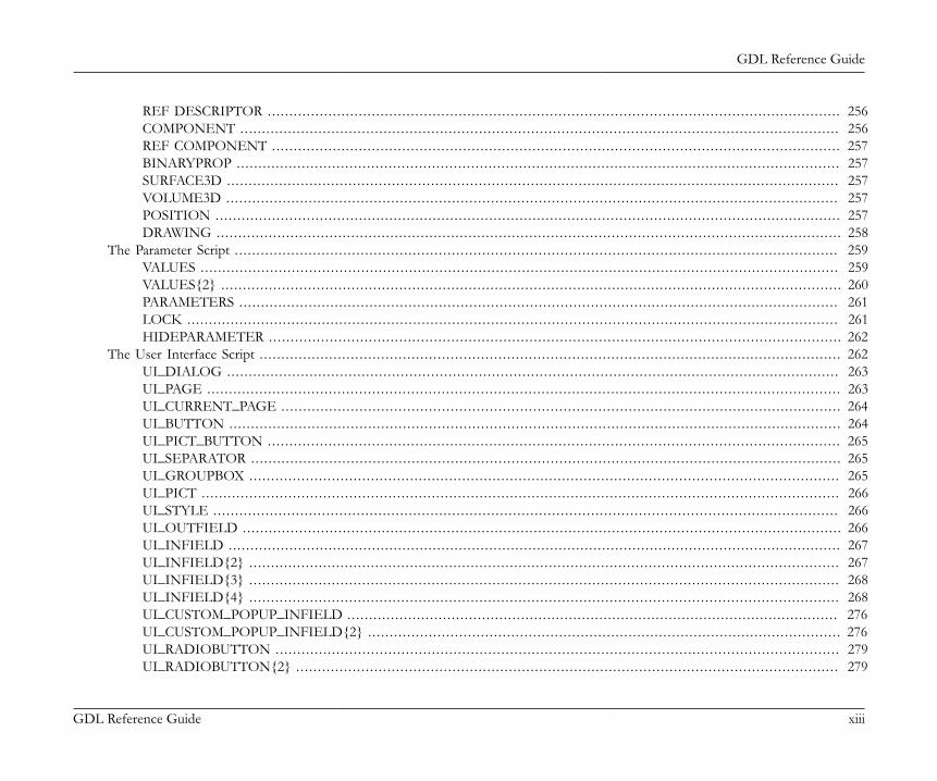
GDL Reference Guide
GDL Reference Guide xiii
REF DESCRIPTOR .. . . . . . . . . . . . . . . . . . . . . . . . . . . . . . . . . . . . . . . . . . . . . . . . . . . . . . . . . . . . . . . . . . . . . . . . . . . . . . . . . . . . . . . . . . . . . . . . . . . . . . . . . . . . . . . . . . . . . . . . . . . . . . . . . . . 256COMPONENT .. . . . . . . . . . . . . . . . . . . . . . . . . . . . . . . . . . . . . . . . . . . . . . . . . . . . . . . . . . . . . . . . . . . . . . . . . . . . . . . . . . . . . . . . . . . . . . . . . . . . . . . . . . . . . . . . . . . . . . . . . . . . . . . . . . . . . . . . . 256REF COMPONENT .. . . . . . . . . . . . . . . . . . . . . . . . . . . . . . . . . . . . . . . . . . . . . . . . . . . . . . . . . . . . . . . . . . . . . . . . . . . . . . . . . . . . . . . . . . . . . . . . . . . . . . . . . . . . . . . . . . . . . . . . . . . . . . . . . . 257BINARYPROP .. . . . . . . . . . . . . . . . . . . . . . . . . . . . . . . . . . . . . . . . . . . . . . . . . . . . . . . . . . . . . . . . . . . . . . . . . . . . . . . . . . . . . . . . . . . . . . . . . . . . . . . . . . . . . . . . . . . . . . . . . . . . . . . . . . . . . . . . . . 257SURFACE3D .. . . . . . . . . . . . . . . . . . . . . . . . . . . . . . . . . . . . . . . . . . . . . . . . . . . . . . . . . . . . . . . . . . . . . . . . . . . . . . . . . . . . . . . . . . . . . . . . . . . . . . . . . . . . . . . . . . . . . . . . . . . . . . . . . . . . . . . . . . . . 257VOLUME3D .. . . . . . . . . . . . . . . . . . . . . . . . . . . . . . . . . . . . . . . . . . . . . . . . . . . . . . . . . . . . . . . . . . . . . . . . . . . . . . . . . . . . . . . . . . . . . . . . . . . . . . . . . . . . . . . . . . . . . . . . . . . . . . . . . . . . . . . . . . . . 257POSITION .. . . . . . . . . . . . . . . . . . . . . . . . . . . . . . . . . . . . . . . . . . . . . . . . . . . . . . . . . . . . . . . . . . . . . . . . . . . . . . . . . . . . . . . . . . . . . . . . . . . . . . . . . . . . . . . . . . . . . . . . . . . . . . . . . . . . . . . . . . . . . . . 257DRAWING .. . . . . . . . . . . . . . . . . . . . . . . . . . . . . . . . . . . . . . . . . . . . . . . . . . . . . . . . . . . . . . . . . . . . . . . . . . . . . . . . . . . . . . . . . . . . . . . . . . . . . . . . . . . . . . . . . . . . . . . . . . . . . . . . . . . . . . . . . . . . . . . 258
The Parameter Script . . . . . . . . . . . . . . . . . . . . . . . . . . . . . . . . . . . . . . . . . . . . . . . . . . . . . . . . . . . . . . . . . . . . . . . . . . . . . . . . . . . . . . . . . . . . . . . . . . . . . . . . . . . . . . . . . . . . . . . . . . . . . . . . . . . . . . . . . . . 259VALUES . . . . . . . . . . . . . . . . . . . . . . . . . . . . . . . . . . . . . . . . . . . . . . . . . . . . . . . . . . . . . . . . . . . . . . . . . . . . . . . . . . . . . . . . . . . . . . . . . . . . . . . . . . . . . . . . . . . . . . . . . . . . . . . . . . . . . . . . . . . . . . . . . . . 259VALUES{2} . . . . . . . . . . . . . . . . . . . . . . . . . . . . . . . . . . . . . . . . . . . . . . . . . . . . . . . . . . . . . . . . . . . . . . . . . . . . . . . . . . . . . . . . . . . . . . . . . . . . . . . . . . . . . . . . . . . . . . . . . . . . . . . . . . . . . . . . . . . . . . . 260PARAMETERS . . . . . . . . . . . . . . . . . . . . . . . . . . . . . . . . . . . . . . . . . . . . . . . . . . . . . . . . . . . . . . . . . . . . . . . . . . . . . . . . . . . . . . . . . . . . . . . . . . . . . . . . . . . . . . . . . . . . . . . . . . . . . . . . . . . . . . . . . . 261LOCK .. . . . . . . . . . . . . . . . . . . . . . . . . . . . . . . . . . . . . . . . . . . . . . . . . . . . . . . . . . . . . . . . . . . . . . . . . . . . . . . . . . . . . . . . . . . . . . . . . . . . . . . . . . . . . . . . . . . . . . . . . . . . . . . . . . . . . . . . . . . . . . . . . . . . . 261HIDEPARAMETER .. . . . . . . . . . . . . . . . . . . . . . . . . . . . . . . . . . . . . . . . . . . . . . . . . . . . . . . . . . . . . . . . . . . . . . . . . . . . . . . . . . . . . . . . . . . . . . . . . . . . . . . . . . . . . . . . . . . . . . . . . . . . . . . . . . . 262
The User Interface Script . . . . . . . . . . . . . . . . . . . . . . . . . . . . . . . . . . . . . . . . . . . . . . . . . . . . . . . . . . . . . . . . . . . . . . . . . . . . . . . . . . . . . . . . . . . . . . . . . . . . . . . . . . . . . . . . . . . . . . . . . . . . . . . . . . . . . . 262UI_DIALOG .. . . . . . . . . . . . . . . . . . . . . . . . . . . . . . . . . . . . . . . . . . . . . . . . . . . . . . . . . . . . . . . . . . . . . . . . . . . . . . . . . . . . . . . . . . . . . . . . . . . . . . . . . . . . . . . . . . . . . . . . . . . . . . . . . . . . . . . . . . . . 263UI_PAGE .. . . . . . . . . . . . . . . . . . . . . . . . . . . . . . . . . . . . . . . . . . . . . . . . . . . . . . . . . . . . . . . . . . . . . . . . . . . . . . . . . . . . . . . . . . . . . . . . . . . . . . . . . . . . . . . . . . . . . . . . . . . . . . . . . . . . . . . . . . . . . . . . . 263UI_CURRENT_PAGE .. . . . . . . . . . . . . . . . . . . . . . . . . . . . . . . . . . . . . . . . . . . . . . . . . . . . . . . . . . . . . . . . . . . . . . . . . . . . . . . . . . . . . . . . . . . . . . . . . . . . . . . . . . . . . . . . . . . . . . . . . . . . . . . . 264UI_BUTTON .. . . . . . . . . . . . . . . . . . . . . . . . . . . . . . . . . . . . . . . . . . . . . . . . . . . . . . . . . . . . . . . . . . . . . . . . . . . . . . . . . . . . . . . . . . . . . . . . . . . . . . . . . . . . . . . . . . . . . . . . . . . . . . . . . . . . . . . . . . . . 264UI_PICT_BUTTON .. . . . . . . . . . . . . . . . . . . . . . . . . . . . . . . . . . . . . . . . . . . . . . . . . . . . . . . . . . . . . . . . . . . . . . . . . . . . . . . . . . . . . . . . . . . . . . . . . . . . . . . . . . . . . . . . . . . . . . . . . . . . . . . . . . . 265UI_SEPARATOR .. . . . . . . . . . . . . . . . . . . . . . . . . . . . . . . . . . . . . . . . . . . . . . . . . . . . . . . . . . . . . . . . . . . . . . . . . . . . . . . . . . . . . . . . . . . . . . . . . . . . . . . . . . . . . . . . . . . . . . . . . . . . . . . . . . . . . . . 265UI_GROUPBOX .. . . . . . . . . . . . . . . . . . . . . . . . . . . . . . . . . . . . . . . . . . . . . . . . . . . . . . . . . . . . . . . . . . . . . . . . . . . . . . . . . . . . . . . . . . . . . . . . . . . . . . . . . . . . . . . . . . . . . . . . . . . . . . . . . . . . . . . 265UI_PICT . . . . . . . . . . . . . . . . . . . . . . . . . . . . . . . . . . . . . . . . . . . . . . . . . . . . . . . . . . . . . . . . . . . . . . . . . . . . . . . . . . . . . . . . . . . . . . . . . . . . . . . . . . . . . . . . . . . . . . . . . . . . . . . . . . . . . . . . . . . . . . . . . . . 266UI_STYLE . . . . . . . . . . . . . . . . . . . . . . . . . . . . . . . . . . . . . . . . . . . . . . . . . . . . . . . . . . . . . . . . . . . . . . . . . . . . . . . . . . . . . . . . . . . . . . . . . . . . . . . . . . . . . . . . . . . . . . . . . . . . . . . . . . . . . . . . . . . . . . . . 266UI_OUTFIELD .. . . . . . . . . . . . . . . . . . . . . . . . . . . . . . . . . . . . . . . . . . . . . . . . . . . . . . . . . . . . . . . . . . . . . . . . . . . . . . . . . . . . . . . . . . . . . . . . . . . . . . . . . . . . . . . . . . . . . . . . . . . . . . . . . . . . . . . . . 266UI_INFIELD .. . . . . . . . . . . . . . . . . . . . . . . . . . . . . . . . . . . . . . . . . . . . . . . . . . . . . . . . . . . . . . . . . . . . . . . . . . . . . . . . . . . . . . . . . . . . . . . . . . . . . . . . . . . . . . . . . . . . . . . . . . . . . . . . . . . . . . . . . . . . 267UI_INFIELD{2} . . . . . . . . . . . . . . . . . . . . . . . . . . . . . . . . . . . . . . . . . . . . . . . . . . . . . . . . . . . . . . . . . . . . . . . . . . . . . . . . . . . . . . . . . . . . . . . . . . . . . . . . . . . . . . . . . . . . . . . . . . . . . . . . . . . . . . . . 267UI_INFIELD{3} . . . . . . . . . . . . . . . . . . . . . . . . . . . . . . . . . . . . . . . . . . . . . . . . . . . . . . . . . . . . . . . . . . . . . . . . . . . . . . . . . . . . . . . . . . . . . . . . . . . . . . . . . . . . . . . . . . . . . . . . . . . . . . . . . . . . . . . . 268UI_INFIELD{4} . . . . . . . . . . . . . . . . . . . . . . . . . . . . . . . . . . . . . . . . . . . . . . . . . . . . . . . . . . . . . . . . . . . . . . . . . . . . . . . . . . . . . . . . . . . . . . . . . . . . . . . . . . . . . . . . . . . . . . . . . . . . . . . . . . . . . . . . 268UI_CUSTOM_POPUP_INFIELD .. . . . . . . . . . . . . . . . . . . . . . . . . . . . . . . . . . . . . . . . . . . . . . . . . . . . . . . . . . . . . . . . . . . . . . . . . . . . . . . . . . . . . . . . . . . . . . . . . . . . . . . . . . . . . . . . 276UI_CUSTOM_POPUP_INFIELD{2} . . . . . . . . . . . . . . . . . . . . . . . . . . . . . . . . . . . . . . . . . . . . . . . . . . . . . . . . . . . . . . . . . . . . . . . . . . . . . . . . . . . . . . . . . . . . . . . . . . . . . . . . . . . . . 276UI_RADIOBUTTON .. . . . . . . . . . . . . . . . . . . . . . . . . . . . . . . . . . . . . . . . . . . . . . . . . . . . . . . . . . . . . . . . . . . . . . . . . . . . . . . . . . . . . . . . . . . . . . . . . . . . . . . . . . . . . . . . . . . . . . . . . . . . . . . . . 279UI_RADIOBUTTON{2} . . . . . . . . . . . . . . . . . . . . . . . . . . . . . . . . . . . . . . . . . . . . . . . . . . . . . . . . . . . . . . . . . . . . . . . . . . . . . . . . . . . . . . . . . . . . . . . . . . . . . . . . . . . . . . . . . . . . . . . . . . . . . 279

GDL Reference Guide
GDL Reference Guide xiv
UI_PICT_RADIOBUTTON .. . . . . . . . . . . . . . . . . . . . . . . . . . . . . . . . . . . . . . . . . . . . . . . . . . . . . . . . . . . . . . . . . . . . . . . . . . . . . . . . . . . . . . . . . . . . . . . . . . . . . . . . . . . . . . . . . . . . . . . . 280UI_PICT_RADIOBUTTON{2} . . . . . . . . . . . . . . . . . . . . . . . . . . . . . . . . . . . . . . . . . . . . . . . . . . . . . . . . . . . . . . . . . . . . . . . . . . . . . . . . . . . . . . . . . . . . . . . . . . . . . . . . . . . . . . . . . . . . 280UI_PICT_PUSHCHECKBUTTON .. . . . . . . . . . . . . . . . . . . . . . . . . . . . . . . . . . . . . . . . . . . . . . . . . . . . . . . . . . . . . . . . . . . . . . . . . . . . . . . . . . . . . . . . . . . . . . . . . . . . . . . . . . . . . . . 280UI_PICT_PUSHCHECKBUTTON{2} . . . . . . . . . . . . . . . . . . . . . . . . . . . . . . . . . . . . . . . . . . . . . . . . . . . . . . . . . . . . . . . . . . . . . . . . . . . . . . . . . . . . . . . . . . . . . . . . . . . . . . . . . . . 280UI_TEXTSTYLE_INFIELD .. . . . . . . . . . . . . . . . . . . . . . . . . . . . . . . . . . . . . . . . . . . . . . . . . . . . . . . . . . . . . . . . . . . . . . . . . . . . . . . . . . . . . . . . . . . . . . . . . . . . . . . . . . . . . . . . . . . . . . . . 281UI_TEXTSTYLE_INFIELD{2} . . . . . . . . . . . . . . . . . . . . . . . . . . . . . . . . . . . . . . . . . . . . . . . . . . . . . . . . . . . . . . . . . . . . . . . . . . . . . . . . . . . . . . . . . . . . . . . . . . . . . . . . . . . . . . . . . . . . 281UI_LISTFIELD .. . . . . . . . . . . . . . . . . . . . . . . . . . . . . . . . . . . . . . . . . . . . . . . . . . . . . . . . . . . . . . . . . . . . . . . . . . . . . . . . . . . . . . . . . . . . . . . . . . . . . . . . . . . . . . . . . . . . . . . . . . . . . . . . . . . . . . . . . 282UI_LISTITEM .. . . . . . . . . . . . . . . . . . . . . . . . . . . . . . . . . . . . . . . . . . . . . . . . . . . . . . . . . . . . . . . . . . . . . . . . . . . . . . . . . . . . . . . . . . . . . . . . . . . . . . . . . . . . . . . . . . . . . . . . . . . . . . . . . . . . . . . . . . 282UI_LISTITEM{2} . . . . . . . . . . . . . . . . . . . . . . . . . . . . . . . . . . . . . . . . . . . . . . . . . . . . . . . . . . . . . . . . . . . . . . . . . . . . . . . . . . . . . . . . . . . . . . . . . . . . . . . . . . . . . . . . . . . . . . . . . . . . . . . . . . . . . . . 283UI_CUSTOM_POPUP_LISTITEM .. . . . . . . . . . . . . . . . . . . . . . . . . . . . . . . . . . . . . . . . . . . . . . . . . . . . . . . . . . . . . . . . . . . . . . . . . . . . . . . . . . . . . . . . . . . . . . . . . . . . . . . . . . . . . . . 284UI_CUSTOM_POPUP_LISTITEM{2} . . . . . . . . . . . . . . . . . . . . . . . . . . . . . . . . . . . . . . . . . . . . . . . . . . . . . . . . . . . . . . . . . . . . . . . . . . . . . . . . . . . . . . . . . . . . . . . . . . . . . . . . . . . 285UI_TOOLTIP . . . . . . . . . . . . . . . . . . . . . . . . . . . . . . . . . . . . . . . . . . . . . . . . . . . . . . . . . . . . . . . . . . . . . . . . . . . . . . . . . . . . . . . . . . . . . . . . . . . . . . . . . . . . . . . . . . . . . . . . . . . . . . . . . . . . . . . . . . . . 287UI_COLORPICKER .. . . . . . . . . . . . . . . . . . . . . . . . . . . . . . . . . . . . . . . . . . . . . . . . . . . . . . . . . . . . . . . . . . . . . . . . . . . . . . . . . . . . . . . . . . . . . . . . . . . . . . . . . . . . . . . . . . . . . . . . . . . . . . . . . . 288UI_COLORPICKER{2} . . . . . . . . . . . . . . . . . . . . . . . . . . . . . . . . . . . . . . . . . . . . . . . . . . . . . . . . . . . . . . . . . . . . . . . . . . . . . . . . . . . . . . . . . . . . . . . . . . . . . . . . . . . . . . . . . . . . . . . . . . . . . . 288UI_SLIDER . . . . . . . . . . . . . . . . . . . . . . . . . . . . . . . . . . . . . . . . . . . . . . . . . . . . . . . . . . . . . . . . . . . . . . . . . . . . . . . . . . . . . . . . . . . . . . . . . . . . . . . . . . . . . . . . . . . . . . . . . . . . . . . . . . . . . . . . . . . . . . . 289UI_SLIDER{2} . . . . . . . . . . . . . . . . . . . . . . . . . . . . . . . . . . . . . . . . . . . . . . . . . . . . . . . . . . . . . . . . . . . . . . . . . . . . . . . . . . . . . . . . . . . . . . . . . . . . . . . . . . . . . . . . . . . . . . . . . . . . . . . . . . . . . . . . . . 289
The Forward Migration Script . . . . . . . . . . . . . . . . . . . . . . . . . . . . . . . . . . . . . . . . . . . . . . . . . . . . . . . . . . . . . . . . . . . . . . . . . . . . . . . . . . . . . . . . . . . . . . . . . . . . . . . . . . . . . . . . . . . . . . . . . . . . . . . . 289SETMIGRATIONGUID .. . . . . . . . . . . . . . . . . . . . . . . . . . . . . . . . . . . . . . . . . . . . . . . . . . . . . . . . . . . . . . . . . . . . . . . . . . . . . . . . . . . . . . . . . . . . . . . . . . . . . . . . . . . . . . . . . . . . . . . . . . . . . 290STORED_PAR_VALUE .. . . . . . . . . . . . . . . . . . . . . . . . . . . . . . . . . . . . . . . . . . . . . . . . . . . . . . . . . . . . . . . . . . . . . . . . . . . . . . . . . . . . . . . . . . . . . . . . . . . . . . . . . . . . . . . . . . . . . . . . . . . . . . 291DELETED_PAR_VALUE .. . . . . . . . . . . . . . . . . . . . . . . . . . . . . . . . . . . . . . . . . . . . . . . . . . . . . . . . . . . . . . . . . . . . . . . . . . . . . . . . . . . . . . . . . . . . . . . . . . . . . . . . . . . . . . . . . . . . . . . . . . . 291
The Backward Migration Script . . . . . . . . . . . . . . . . . . . . . . . . . . . . . . . . . . . . . . . . . . . . . . . . . . . . . . . . . . . . . . . . . . . . . . . . . . . . . . . . . . . . . . . . . . . . . . . . . . . . . . . . . . . . . . . . . . . . . . . . . . . . . . 291NEWPARAMETER .. . . . . . . . . . . . . . . . . . . . . . . . . . . . . . . . . . . . . . . . . . . . . . . . . . . . . . . . . . . . . . . . . . . . . . . . . . . . . . . . . . . . . . . . . . . . . . . . . . . . . . . . . . . . . . . . . . . . . . . . . . . . . . . . . . . 293
Expressions and Functions . . . . . . . . . . . . . . . . . . . . . . . . . . . . . . . . . . . . . . . . . . . . . . . . . . . . . . . . . . . . . . . . . . . . . . . . . . . . . . . . . . . . . . . . . . . . . . . . . . . . . . . . . . . . . . . . . . . . . . . . . . . . . . . . . . . . . . . . . . . . 294Expressions . . . . . . . . . . . . . . . . . . . . . . . . . . . . . . . . . . . . . . . . . . . . . . . . . . . . . . . . . . . . . . . . . . . . . . . . . . . . . . . . . . . . . . . . . . . . . . . . . . . . . . . . . . . . . . . . . . . . . . . . . . . . . . . . . . . . . . . . . . . . . . . . . . . . . . . . 294
DICT . . . . . . . . . . . . . . . . . . . . . . . . . . . . . . . . . . . . . . . . . . . . . . . . . . . . . . . . . . . . . . . . . . . . . . . . . . . . . . . . . . . . . . . . . . . . . . . . . . . . . . . . . . . . . . . . . . . . . . . . . . . . . . . . . . . . . . . . . . . . . . . . . . . . . . . . 294HASKEY .. . . . . . . . . . . . . . . . . . . . . . . . . . . . . . . . . . . . . . . . . . . . . . . . . . . . . . . . . . . . . . . . . . . . . . . . . . . . . . . . . . . . . . . . . . . . . . . . . . . . . . . . . . . . . . . . . . . . . . . . . . . . . . . . . . . . . . . . . . . . . . . . . 299REMOVEKEY .. . . . . . . . . . . . . . . . . . . . . . . . . . . . . . . . . . . . . . . . . . . . . . . . . . . . . . . . . . . . . . . . . . . . . . . . . . . . . . . . . . . . . . . . . . . . . . . . . . . . . . . . . . . . . . . . . . . . . . . . . . . . . . . . . . . . . . . . . . 299DIM .. . . . . . . . . . . . . . . . . . . . . . . . . . . . . . . . . . . . . . . . . . . . . . . . . . . . . . . . . . . . . . . . . . . . . . . . . . . . . . . . . . . . . . . . . . . . . . . . . . . . . . . . . . . . . . . . . . . . . . . . . . . . . . . . . . . . . . . . . . . . . . . . . . . . . . . . 300VARDIM1 . . . . . . . . . . . . . . . . . . . . . . . . . . . . . . . . . . . . . . . . . . . . . . . . . . . . . . . . . . . . . . . . . . . . . . . . . . . . . . . . . . . . . . . . . . . . . . . . . . . . . . . . . . . . . . . . . . . . . . . . . . . . . . . . . . . . . . . . . . . . . . . . . 301VARDIM2 . . . . . . . . . . . . . . . . . . . . . . . . . . . . . . . . . . . . . . . . . . . . . . . . . . . . . . . . . . . . . . . . . . . . . . . . . . . . . . . . . . . . . . . . . . . . . . . . . . . . . . . . . . . . . . . . . . . . . . . . . . . . . . . . . . . . . . . . . . . . . . . . . 301PARVALUE_DESCRIPTION .. . . . . . . . . . . . . . . . . . . . . . . . . . . . . . . . . . . . . . . . . . . . . . . . . . . . . . . . . . . . . . . . . . . . . . . . . . . . . . . . . . . . . . . . . . . . . . . . . . . . . . . . . . . . . . . . . . . . . . 304
Operators . . . . . . . . . . . . . . . . . . . . . . . . . . . . . . . . . . . . . . . . . . . . . . . . . . . . . . . . . . . . . . . . . . . . . . . . . . . . . . . . . . . . . . . . . . . . . . . . . . . . . . . . . . . . . . . . . . . . . . . . . . . . . . . . . . . . . . . . . . . . . . . . . . . . . . . . . . 304Arithmetical Operators . . . . . . . . . . . . . . . . . . . . . . . . . . . . . . . . . . . . . . . . . . . . . . . . . . . . . . . . . . . . . . . . . . . . . . . . . . . . . . . . . . . . . . . . . . . . . . . . . . . . . . . . . . . . . . . . . . . . . . . . . . . . . . . . . 304
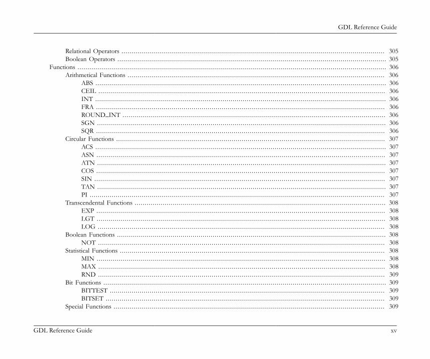
GDL Reference Guide
GDL Reference Guide xv
Relational Operators . . . . . . . . . . . . . . . . . . . . . . . . . . . . . . . . . . . . . . . . . . . . . . . . . . . . . . . . . . . . . . . . . . . . . . . . . . . . . . . . . . . . . . . . . . . . . . . . . . . . . . . . . . . . . . . . . . . . . . . . . . . . . . . . . . . . 305Boolean Operators . . . . . . . . . . . . . . . . . . . . . . . . . . . . . . . . . . . . . . . . . . . . . . . . . . . . . . . . . . . . . . . . . . . . . . . . . . . . . . . . . . . . . . . . . . . . . . . . . . . . . . . . . . . . . . . . . . . . . . . . . . . . . . . . . . . . . . . 305
Functions . . . . . . . . . . . . . . . . . . . . . . . . . . . . . . . . . . . . . . . . . . . . . . . . . . . . . . . . . . . . . . . . . . . . . . . . . . . . . . . . . . . . . . . . . . . . . . . . . . . . . . . . . . . . . . . . . . . . . . . . . . . . . . . . . . . . . . . . . . . . . . . . . . . . . . . . . . . 306Arithmetical Functions . . . . . . . . . . . . . . . . . . . . . . . . . . . . . . . . . . . . . . . . . . . . . . . . . . . . . . . . . . . . . . . . . . . . . . . . . . . . . . . . . . . . . . . . . . . . . . . . . . . . . . . . . . . . . . . . . . . . . . . . . . . . . . . . . 306
ABS . . . . . . . . . . . . . . . . . . . . . . . . . . . . . . . . . . . . . . . . . . . . . . . . . . . . . . . . . . . . . . . . . . . . . . . . . . . . . . . . . . . . . . . . . . . . . . . . . . . . . . . . . . . . . . . . . . . . . . . . . . . . . . . . . . . . . . . . . . . . . . . . . . 306CEIL . . . . . . . . . . . . . . . . . . . . . . . . . . . . . . . . . . . . . . . . . . . . . . . . . . . . . . . . . . . . . . . . . . . . . . . . . . . . . . . . . . . . . . . . . . . . . . . . . . . . . . . . . . . . . . . . . . . . . . . . . . . . . . . . . . . . . . . . . . . . . . . . 306INT . . . . . . . . . . . . . . . . . . . . . . . . . . . . . . . . . . . . . . . . . . . . . . . . . . . . . . . . . . . . . . . . . . . . . . . . . . . . . . . . . . . . . . . . . . . . . . . . . . . . . . . . . . . . . . . . . . . . . . . . . . . . . . . . . . . . . . . . . . . . . . . . . . 306FRA . . . . . . . . . . . . . . . . . . . . . . . . . . . . . . . . . . . . . . . . . . . . . . . . . . . . . . . . . . . . . . . . . . . . . . . . . . . . . . . . . . . . . . . . . . . . . . . . . . . . . . . . . . . . . . . . . . . . . . . . . . . . . . . . . . . . . . . . . . . . . . . . . 306ROUND_INT . . . . . . . . . . . . . . . . . . . . . . . . . . . . . . . . . . . . . . . . . . . . . . . . . . . . . . . . . . . . . . . . . . . . . . . . . . . . . . . . . . . . . . . . . . . . . . . . . . . . . . . . . . . . . . . . . . . . . . . . . . . . . . . . . . . . 306SGN .. . . . . . . . . . . . . . . . . . . . . . . . . . . . . . . . . . . . . . . . . . . . . . . . . . . . . . . . . . . . . . . . . . . . . . . . . . . . . . . . . . . . . . . . . . . . . . . . . . . . . . . . . . . . . . . . . . . . . . . . . . . . . . . . . . . . . . . . . . . . . . . . 306SQR . . . . . . . . . . . . . . . . . . . . . . . . . . . . . . . . . . . . . . . . . . . . . . . . . . . . . . . . . . . . . . . . . . . . . . . . . . . . . . . . . . . . . . . . . . . . . . . . . . . . . . . . . . . . . . . . . . . . . . . . . . . . . . . . . . . . . . . . . . . . . . . . . 306
Circular Functions . . . . . . . . . . . . . . . . . . . . . . . . . . . . . . . . . . . . . . . . . . . . . . . . . . . . . . . . . . . . . . . . . . . . . . . . . . . . . . . . . . . . . . . . . . . . . . . . . . . . . . . . . . . . . . . . . . . . . . . . . . . . . . . . . . . . . . . 307ACS . . . . . . . . . . . . . . . . . . . . . . . . . . . . . . . . . . . . . . . . . . . . . . . . . . . . . . . . . . . . . . . . . . . . . . . . . . . . . . . . . . . . . . . . . . . . . . . . . . . . . . . . . . . . . . . . . . . . . . . . . . . . . . . . . . . . . . . . . . . . . . . . . . 307ASN .. . . . . . . . . . . . . . . . . . . . . . . . . . . . . . . . . . . . . . . . . . . . . . . . . . . . . . . . . . . . . . . . . . . . . . . . . . . . . . . . . . . . . . . . . . . . . . . . . . . . . . . . . . . . . . . . . . . . . . . . . . . . . . . . . . . . . . . . . . . . . . . . 307ATN .. . . . . . . . . . . . . . . . . . . . . . . . . . . . . . . . . . . . . . . . . . . . . . . . . . . . . . . . . . . . . . . . . . . . . . . . . . . . . . . . . . . . . . . . . . . . . . . . . . . . . . . . . . . . . . . . . . . . . . . . . . . . . . . . . . . . . . . . . . . . . . . . 307COS . . . . . . . . . . . . . . . . . . . . . . . . . . . . . . . . . . . . . . . . . . . . . . . . . . . . . . . . . . . . . . . . . . . . . . . . . . . . . . . . . . . . . . . . . . . . . . . . . . . . . . . . . . . . . . . . . . . . . . . . . . . . . . . . . . . . . . . . . . . . . . . . . 307SIN . . . . . . . . . . . . . . . . . . . . . . . . . . . . . . . . . . . . . . . . . . . . . . . . . . . . . . . . . . . . . . . . . . . . . . . . . . . . . . . . . . . . . . . . . . . . . . . . . . . . . . . . . . . . . . . . . . . . . . . . . . . . . . . . . . . . . . . . . . . . . . . . . . 307TAN .. . . . . . . . . . . . . . . . . . . . . . . . . . . . . . . . . . . . . . . . . . . . . . . . . . . . . . . . . . . . . . . . . . . . . . . . . . . . . . . . . . . . . . . . . . . . . . . . . . . . . . . . . . . . . . . . . . . . . . . . . . . . . . . . . . . . . . . . . . . . . . . . 307PI . . . . . . . . . . . . . . . . . . . . . . . . . . . . . . . . . . . . . . . . . . . . . . . . . . . . . . . . . . . . . . . . . . . . . . . . . . . . . . . . . . . . . . . . . . . . . . . . . . . . . . . . . . . . . . . . . . . . . . . . . . . . . . . . . . . . . . . . . . . . . . . . . . . . 307
Transcendental Functions . . . . . . . . . . . . . . . . . . . . . . . . . . . . . . . . . . . . . . . . . . . . . . . . . . . . . . . . . . . . . . . . . . . . . . . . . . . . . . . . . . . . . . . . . . . . . . . . . . . . . . . . . . . . . . . . . . . . . . . . . . . . . . 308EXP . . . . . . . . . . . . . . . . . . . . . . . . . . . . . . . . . . . . . . . . . . . . . . . . . . . . . . . . . . . . . . . . . . . . . . . . . . . . . . . . . . . . . . . . . . . . . . . . . . . . . . . . . . . . . . . . . . . . . . . . . . . . . . . . . . . . . . . . . . . . . . . . . 308LGT . . . . . . . . . . . . . . . . . . . . . . . . . . . . . . . . . . . . . . . . . . . . . . . . . . . . . . . . . . . . . . . . . . . . . . . . . . . . . . . . . . . . . . . . . . . . . . . . . . . . . . . . . . . . . . . . . . . . . . . . . . . . . . . . . . . . . . . . . . . . . . . . . 308LOG .. . . . . . . . . . . . . . . . . . . . . . . . . . . . . . . . . . . . . . . . . . . . . . . . . . . . . . . . . . . . . . . . . . . . . . . . . . . . . . . . . . . . . . . . . . . . . . . . . . . . . . . . . . . . . . . . . . . . . . . . . . . . . . . . . . . . . . . . . . . . . . . 308
Boolean Functions . . . . . . . . . . . . . . . . . . . . . . . . . . . . . . . . . . . . . . . . . . . . . . . . . . . . . . . . . . . . . . . . . . . . . . . . . . . . . . . . . . . . . . . . . . . . . . . . . . . . . . . . . . . . . . . . . . . . . . . . . . . . . . . . . . . . . . . 308NOT .. . . . . . . . . . . . . . . . . . . . . . . . . . . . . . . . . . . . . . . . . . . . . . . . . . . . . . . . . . . . . . . . . . . . . . . . . . . . . . . . . . . . . . . . . . . . . . . . . . . . . . . . . . . . . . . . . . . . . . . . . . . . . . . . . . . . . . . . . . . . . . . 308
Statistical Functions . . . . . . . . . . . . . . . . . . . . . . . . . . . . . . . . . . . . . . . . . . . . . . . . . . . . . . . . . . . . . . . . . . . . . . . . . . . . . . . . . . . . . . . . . . . . . . . . . . . . . . . . . . . . . . . . . . . . . . . . . . . . . . . . . . . . . 308MIN .. . . . . . . . . . . . . . . . . . . . . . . . . . . . . . . . . . . . . . . . . . . . . . . . . . . . . . . . . . . . . . . . . . . . . . . . . . . . . . . . . . . . . . . . . . . . . . . . . . . . . . . . . . . . . . . . . . . . . . . . . . . . . . . . . . . . . . . . . . . . . . . . 308MAX .. . . . . . . . . . . . . . . . . . . . . . . . . . . . . . . . . . . . . . . . . . . . . . . . . . . . . . . . . . . . . . . . . . . . . . . . . . . . . . . . . . . . . . . . . . . . . . . . . . . . . . . . . . . . . . . . . . . . . . . . . . . . . . . . . . . . . . . . . . . . . . . 308RND .. . . . . . . . . . . . . . . . . . . . . . . . . . . . . . . . . . . . . . . . . . . . . . . . . . . . . . . . . . . . . . . . . . . . . . . . . . . . . . . . . . . . . . . . . . . . . . . . . . . . . . . . . . . . . . . . . . . . . . . . . . . . . . . . . . . . . . . . . . . . . . . 309
Bit Functions . . . . . . . . . . . . . . . . . . . . . . . . . . . . . . . . . . . . . . . . . . . . . . . . . . . . . . . . . . . . . . . . . . . . . . . . . . . . . . . . . . . . . . . . . . . . . . . . . . . . . . . . . . . . . . . . . . . . . . . . . . . . . . . . . . . . . . . . . . . . . . 309BITTEST . . . . . . . . . . . . . . . . . . . . . . . . . . . . . . . . . . . . . . . . . . . . . . . . . . . . . . . . . . . . . . . . . . . . . . . . . . . . . . . . . . . . . . . . . . . . . . . . . . . . . . . . . . . . . . . . . . . . . . . . . . . . . . . . . . . . . . . . . . 309BITSET . . . . . . . . . . . . . . . . . . . . . . . . . . . . . . . . . . . . . . . . . . . . . . . . . . . . . . . . . . . . . . . . . . . . . . . . . . . . . . . . . . . . . . . . . . . . . . . . . . . . . . . . . . . . . . . . . . . . . . . . . . . . . . . . . . . . . . . . . . . . 309
Special Functions . . . . . . . . . . . . . . . . . . . . . . . . . . . . . . . . . . . . . . . . . . . . . . . . . . . . . . . . . . . . . . . . . . . . . . . . . . . . . . . . . . . . . . . . . . . . . . . . . . . . . . . . . . . . . . . . . . . . . . . . . . . . . . . . . . . . . . . . 309

GDL Reference Guide
GDL Reference Guide xvi
REQ .. . . . . . . . . . . . . . . . . . . . . . . . . . . . . . . . . . . . . . . . . . . . . . . . . . . . . . . . . . . . . . . . . . . . . . . . . . . . . . . . . . . . . . . . . . . . . . . . . . . . . . . . . . . . . . . . . . . . . . . . . . . . . . . . . . . . . . . . . . . . . . . . 309REQUEST . . . . . . . . . . . . . . . . . . . . . . . . . . . . . . . . . . . . . . . . . . . . . . . . . . . . . . . . . . . . . . . . . . . . . . . . . . . . . . . . . . . . . . . . . . . . . . . . . . . . . . . . . . . . . . . . . . . . . . . . . . . . . . . . . . . . . . . . . 310IND .. . . . . . . . . . . . . . . . . . . . . . . . . . . . . . . . . . . . . . . . . . . . . . . . . . . . . . . . . . . . . . . . . . . . . . . . . . . . . . . . . . . . . . . . . . . . . . . . . . . . . . . . . . . . . . . . . . . . . . . . . . . . . . . . . . . . . . . . . . . . . . . . 310APPLICATION_QUERY .. . . . . . . . . . . . . . . . . . . . . . . . . . . . . . . . . . . . . . . . . . . . . . . . . . . . . . . . . . . . . . . . . . . . . . . . . . . . . . . . . . . . . . . . . . . . . . . . . . . . . . . . . . . . . . . . . . . . 311LIBRARYGLOBAL . . . . . . . . . . . . . . . . . . . . . . . . . . . . . . . . . . . . . . . . . . . . . . . . . . . . . . . . . . . . . . . . . . . . . . . . . . . . . . . . . . . . . . . . . . . . . . . . . . . . . . . . . . . . . . . . . . . . . . . . . . . . . 311
String Functions . . . . . . . . . . . . . . . . . . . . . . . . . . . . . . . . . . . . . . . . . . . . . . . . . . . . . . . . . . . . . . . . . . . . . . . . . . . . . . . . . . . . . . . . . . . . . . . . . . . . . . . . . . . . . . . . . . . . . . . . . . . . . . . . . . . . . . . . . . 311STR . . . . . . . . . . . . . . . . . . . . . . . . . . . . . . . . . . . . . . . . . . . . . . . . . . . . . . . . . . . . . . . . . . . . . . . . . . . . . . . . . . . . . . . . . . . . . . . . . . . . . . . . . . . . . . . . . . . . . . . . . . . . . . . . . . . . . . . . . . . . . . . . . . 311STR{2} . . . . . . . . . . . . . . . . . . . . . . . . . . . . . . . . . . . . . . . . . . . . . . . . . . . . . . . . . . . . . . . . . . . . . . . . . . . . . . . . . . . . . . . . . . . . . . . . . . . . . . . . . . . . . . . . . . . . . . . . . . . . . . . . . . . . . . . . . . . . . 312SPLIT . . . . . . . . . . . . . . . . . . . . . . . . . . . . . . . . . . . . . . . . . . . . . . . . . . . . . . . . . . . . . . . . . . . . . . . . . . . . . . . . . . . . . . . . . . . . . . . . . . . . . . . . . . . . . . . . . . . . . . . . . . . . . . . . . . . . . . . . . . . . . . . 315STW .. . . . . . . . . . . . . . . . . . . . . . . . . . . . . . . . . . . . . . . . . . . . . . . . . . . . . . . . . . . . . . . . . . . . . . . . . . . . . . . . . . . . . . . . . . . . . . . . . . . . . . . . . . . . . . . . . . . . . . . . . . . . . . . . . . . . . . . . . . . . . . . . 316STRLEN .. . . . . . . . . . . . . . . . . . . . . . . . . . . . . . . . . . . . . . . . . . . . . . . . . . . . . . . . . . . . . . . . . . . . . . . . . . . . . . . . . . . . . . . . . . . . . . . . . . . . . . . . . . . . . . . . . . . . . . . . . . . . . . . . . . . . . . . . . . 316STRSTR . . . . . . . . . . . . . . . . . . . . . . . . . . . . . . . . . . . . . . . . . . . . . . . . . . . . . . . . . . . . . . . . . . . . . . . . . . . . . . . . . . . . . . . . . . . . . . . . . . . . . . . . . . . . . . . . . . . . . . . . . . . . . . . . . . . . . . . . . . . . 317STRSUB . . . . . . . . . . . . . . . . . . . . . . . . . . . . . . . . . . . . . . . . . . . . . . . . . . . . . . . . . . . . . . . . . . . . . . . . . . . . . . . . . . . . . . . . . . . . . . . . . . . . . . . . . . . . . . . . . . . . . . . . . . . . . . . . . . . . . . . . . . . . 317STRTOUPPER . . . . . . . . . . . . . . . . . . . . . . . . . . . . . . . . . . . . . . . . . . . . . . . . . . . . . . . . . . . . . . . . . . . . . . . . . . . . . . . . . . . . . . . . . . . . . . . . . . . . . . . . . . . . . . . . . . . . . . . . . . . . . . . . . . . 318STRTOLOWER .. . . . . . . . . . . . . . . . . . . . . . . . . . . . . . . . . . . . . . . . . . . . . . . . . . . . . . . . . . . . . . . . . . . . . . . . . . . . . . . . . . . . . . . . . . . . . . . . . . . . . . . . . . . . . . . . . . . . . . . . . . . . . . . . . 318
Control Statements . . . . . . . . . . . . . . . . . . . . . . . . . . . . . . . . . . . . . . . . . . . . . . . . . . . . . . . . . . . . . . . . . . . . . . . . . . . . . . . . . . . . . . . . . . . . . . . . . . . . . . . . . . . . . . . . . . . . . . . . . . . . . . . . . . . . . . . . . . . . . . . . . . . . . . 319Flow Control Statements . . . . . . . . . . . . . . . . . . . . . . . . . . . . . . . . . . . . . . . . . . . . . . . . . . . . . . . . . . . . . . . . . . . . . . . . . . . . . . . . . . . . . . . . . . . . . . . . . . . . . . . . . . . . . . . . . . . . . . . . . . . . . . . . . . . . . . . 319
FOR - TO - NEXT .. . . . . . . . . . . . . . . . . . . . . . . . . . . . . . . . . . . . . . . . . . . . . . . . . . . . . . . . . . . . . . . . . . . . . . . . . . . . . . . . . . . . . . . . . . . . . . . . . . . . . . . . . . . . . . . . . . . . . . . . . . . . . . . . . . . 319DO - WHILE . . . . . . . . . . . . . . . . . . . . . . . . . . . . . . . . . . . . . . . . . . . . . . . . . . . . . . . . . . . . . . . . . . . . . . . . . . . . . . . . . . . . . . . . . . . . . . . . . . . . . . . . . . . . . . . . . . . . . . . . . . . . . . . . . . . . . . . . . . . . 320WHILE - ENDWHILE . . . . . . . . . . . . . . . . . . . . . . . . . . . . . . . . . . . . . . . . . . . . . . . . . . . . . . . . . . . . . . . . . . . . . . . . . . . . . . . . . . . . . . . . . . . . . . . . . . . . . . . . . . . . . . . . . . . . . . . . . . . . . . . 320REPEAT - UNTIL . . . . . . . . . . . . . . . . . . . . . . . . . . . . . . . . . . . . . . . . . . . . . . . . . . . . . . . . . . . . . . . . . . . . . . . . . . . . . . . . . . . . . . . . . . . . . . . . . . . . . . . . . . . . . . . . . . . . . . . . . . . . . . . . . . . . . . 321IF - GOTO .. . . . . . . . . . . . . . . . . . . . . . . . . . . . . . . . . . . . . . . . . . . . . . . . . . . . . . . . . . . . . . . . . . . . . . . . . . . . . . . . . . . . . . . . . . . . . . . . . . . . . . . . . . . . . . . . . . . . . . . . . . . . . . . . . . . . . . . . . . . . . . 322IF - THEN - ELSE - ENDIF . . . . . . . . . . . . . . . . . . . . . . . . . . . . . . . . . . . . . . . . . . . . . . . . . . . . . . . . . . . . . . . . . . . . . . . . . . . . . . . . . . . . . . . . . . . . . . . . . . . . . . . . . . . . . . . . . . . . . . . 323GOTO .. . . . . . . . . . . . . . . . . . . . . . . . . . . . . . . . . . . . . . . . . . . . . . . . . . . . . . . . . . . . . . . . . . . . . . . . . . . . . . . . . . . . . . . . . . . . . . . . . . . . . . . . . . . . . . . . . . . . . . . . . . . . . . . . . . . . . . . . . . . . . . . . . . . . . 324GOSUB .. . . . . . . . . . . . . . . . . . . . . . . . . . . . . . . . . . . . . . . . . . . . . . . . . . . . . . . . . . . . . . . . . . . . . . . . . . . . . . . . . . . . . . . . . . . . . . . . . . . . . . . . . . . . . . . . . . . . . . . . . . . . . . . . . . . . . . . . . . . . . . . . . . . 324RETURN .. . . . . . . . . . . . . . . . . . . . . . . . . . . . . . . . . . . . . . . . . . . . . . . . . . . . . . . . . . . . . . . . . . . . . . . . . . . . . . . . . . . . . . . . . . . . . . . . . . . . . . . . . . . . . . . . . . . . . . . . . . . . . . . . . . . . . . . . . . . . . . . . . 324END / EXIT . . . . . . . . . . . . . . . . . . . . . . . . . . . . . . . . . . . . . . . . . . . . . . . . . . . . . . . . . . . . . . . . . . . . . . . . . . . . . . . . . . . . . . . . . . . . . . . . . . . . . . . . . . . . . . . . . . . . . . . . . . . . . . . . . . . . . . . . . . . . . 325BREAKPOINT .. . . . . . . . . . . . . . . . . . . . . . . . . . . . . . . . . . . . . . . . . . . . . . . . . . . . . . . . . . . . . . . . . . . . . . . . . . . . . . . . . . . . . . . . . . . . . . . . . . . . . . . . . . . . . . . . . . . . . . . . . . . . . . . . . . . . . . . . . 325
Parameter Buffer Manipulation . . . . . . . . . . . . . . . . . . . . . . . . . . . . . . . . . . . . . . . . . . . . . . . . . . . . . . . . . . . . . . . . . . . . . . . . . . . . . . . . . . . . . . . . . . . . . . . . . . . . . . . . . . . . . . . . . . . . . . . . . . . . . . . 325PUT . . . . . . . . . . . . . . . . . . . . . . . . . . . . . . . . . . . . . . . . . . . . . . . . . . . . . . . . . . . . . . . . . . . . . . . . . . . . . . . . . . . . . . . . . . . . . . . . . . . . . . . . . . . . . . . . . . . . . . . . . . . . . . . . . . . . . . . . . . . . . . . . . . . . . . . . . 326GET . . . . . . . . . . . . . . . . . . . . . . . . . . . . . . . . . . . . . . . . . . . . . . . . . . . . . . . . . . . . . . . . . . . . . . . . . . . . . . . . . . . . . . . . . . . . . . . . . . . . . . . . . . . . . . . . . . . . . . . . . . . . . . . . . . . . . . . . . . . . . . . . . . . . . . . . . 326USE . . . . . . . . . . . . . . . . . . . . . . . . . . . . . . . . . . . . . . . . . . . . . . . . . . . . . . . . . . . . . . . . . . . . . . . . . . . . . . . . . . . . . . . . . . . . . . . . . . . . . . . . . . . . . . . . . . . . . . . . . . . . . . . . . . . . . . . . . . . . . . . . . . . . . . . . . 326NSP . . . . . . . . . . . . . . . . . . . . . . . . . . . . . . . . . . . . . . . . . . . . . . . . . . . . . . . . . . . . . . . . . . . . . . . . . . . . . . . . . . . . . . . . . . . . . . . . . . . . . . . . . . . . . . . . . . . . . . . . . . . . . . . . . . . . . . . . . . . . . . . . . . . . . . . . . . 326
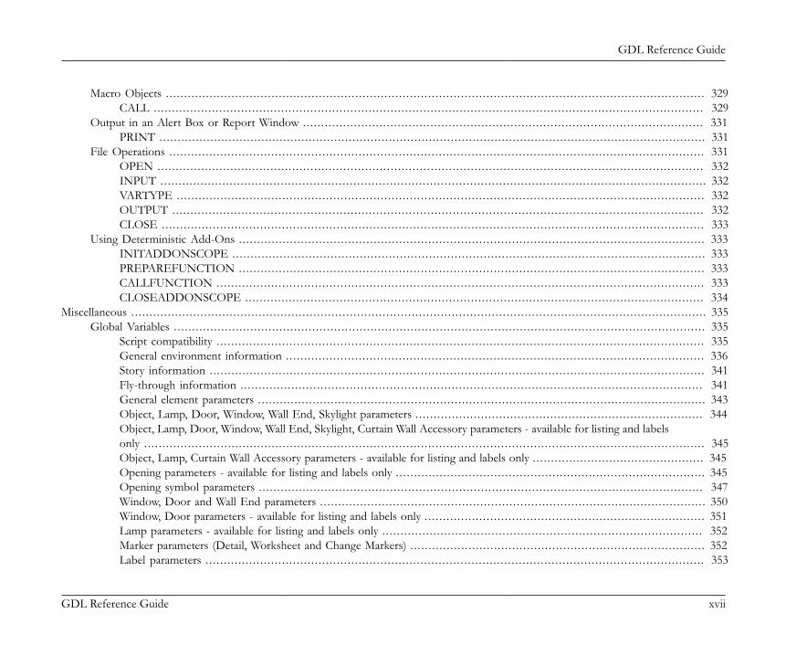
GDL Reference Guide
GDL Reference Guide xvii
Macro Objects . . . . . . . . . . . . . . . . . . . . . . . . . . . . . . . . . . . . . . . . . . . . . . . . . . . . . . . . . . . . . . . . . . . . . . . . . . . . . . . . . . . . . . . . . . . . . . . . . . . . . . . . . . . . . . . . . . . . . . . . . . . . . . . . . . . . . . . . . . . . . . . . . . . . 329CALL . . . . . . . . . . . . . . . . . . . . . . . . . . . . . . . . . . . . . . . . . . . . . . . . . . . . . . . . . . . . . . . . . . . . . . . . . . . . . . . . . . . . . . . . . . . . . . . . . . . . . . . . . . . . . . . . . . . . . . . . . . . . . . . . . . . . . . . . . . . . . . . . . . . . . . . 329
Output in an Alert Box or Report Window . . . . . . . . . . . . . . . . . . . . . . . . . . . . . . . . . . . . . . . . . . . . . . . . . . . . . . . . . . . . . . . . . . . . . . . . . . . . . . . . . . . . . . . . . . . . . . . . . . . . . . . . . . . . . . 331PRINT . . . . . . . . . . . . . . . . . . . . . . . . . . . . . . . . . . . . . . . . . . . . . . . . . . . . . . . . . . . . . . . . . . . . . . . . . . . . . . . . . . . . . . . . . . . . . . . . . . . . . . . . . . . . . . . . . . . . . . . . . . . . . . . . . . . . . . . . . . . . . . . . . . . . . . 331
File Operations . . . . . . . . . . . . . . . . . . . . . . . . . . . . . . . . . . . . . . . . . . . . . . . . . . . . . . . . . . . . . . . . . . . . . . . . . . . . . . . . . . . . . . . . . . . . . . . . . . . . . . . . . . . . . . . . . . . . . . . . . . . . . . . . . . . . . . . . . . . . . . . . . . . 331OPEN .. . . . . . . . . . . . . . . . . . . . . . . . . . . . . . . . . . . . . . . . . . . . . . . . . . . . . . . . . . . . . . . . . . . . . . . . . . . . . . . . . . . . . . . . . . . . . . . . . . . . . . . . . . . . . . . . . . . . . . . . . . . . . . . . . . . . . . . . . . . . . . . . . . . . . 332INPUT . . . . . . . . . . . . . . . . . . . . . . . . . . . . . . . . . . . . . . . . . . . . . . . . . . . . . . . . . . . . . . . . . . . . . . . . . . . . . . . . . . . . . . . . . . . . . . . . . . . . . . . . . . . . . . . . . . . . . . . . . . . . . . . . . . . . . . . . . . . . . . . . . . . . . . 332VARTYPE . . . . . . . . . . . . . . . . . . . . . . . . . . . . . . . . . . . . . . . . . . . . . . . . . . . . . . . . . . . . . . . . . . . . . . . . . . . . . . . . . . . . . . . . . . . . . . . . . . . . . . . . . . . . . . . . . . . . . . . . . . . . . . . . . . . . . . . . . . . . . . . . . 332OUTPUT .. . . . . . . . . . . . . . . . . . . . . . . . . . . . . . . . . . . . . . . . . . . . . . . . . . . . . . . . . . . . . . . . . . . . . . . . . . . . . . . . . . . . . . . . . . . . . . . . . . . . . . . . . . . . . . . . . . . . . . . . . . . . . . . . . . . . . . . . . . . . . . . . . 332CLOSE . . . . . . . . . . . . . . . . . . . . . . . . . . . . . . . . . . . . . . . . . . . . . . . . . . . . . . . . . . . . . . . . . . . . . . . . . . . . . . . . . . . . . . . . . . . . . . . . . . . . . . . . . . . . . . . . . . . . . . . . . . . . . . . . . . . . . . . . . . . . . . . . . . . . . 333
Using Deterministic Add-Ons . . . . . . . . . . . . . . . . . . . . . . . . . . . . . . . . . . . . . . . . . . . . . . . . . . . . . . . . . . . . . . . . . . . . . . . . . . . . . . . . . . . . . . . . . . . . . . . . . . . . . . . . . . . . . . . . . . . . . . . . . . . . . . . . 333INITADDONSCOPE .. . . . . . . . . . . . . . . . . . . . . . . . . . . . . . . . . . . . . . . . . . . . . . . . . . . . . . . . . . . . . . . . . . . . . . . . . . . . . . . . . . . . . . . . . . . . . . . . . . . . . . . . . . . . . . . . . . . . . . . . . . . . . . . . . 333PREPAREFUNCTION .. . . . . . . . . . . . . . . . . . . . . . . . . . . . . . . . . . . . . . . . . . . . . . . . . . . . . . . . . . . . . . . . . . . . . . . . . . . . . . . . . . . . . . . . . . . . . . . . . . . . . . . . . . . . . . . . . . . . . . . . . . . . . . . 333CALLFUNCTION .. . . . . . . . . . . . . . . . . . . . . . . . . . . . . . . . . . . . . . . . . . . . . . . . . . . . . . . . . . . . . . . . . . . . . . . . . . . . . . . . . . . . . . . . . . . . . . . . . . . . . . . . . . . . . . . . . . . . . . . . . . . . . . . . . . . . . 333CLOSEADDONSCOPE .. . . . . . . . . . . . . . . . . . . . . . . . . . . . . . . . . . . . . . . . . . . . . . . . . . . . . . . . . . . . . . . . . . . . . . . . . . . . . . . . . . . . . . . . . . . . . . . . . . . . . . . . . . . . . . . . . . . . . . . . . . . . . 334
Miscellaneous . . . . . . . . . . . . . . . . . . . . . . . . . . . . . . . . . . . . . . . . . . . . . . . . . . . . . . . . . . . . . . . . . . . . . . . . . . . . . . . . . . . . . . . . . . . . . . . . . . . . . . . . . . . . . . . . . . . . . . . . . . . . . . . . . . . . . . . . . . . . . . . . . . . . . . . . . . . . . . 335Global Variables . . . . . . . . . . . . . . . . . . . . . . . . . . . . . . . . . . . . . . . . . . . . . . . . . . . . . . . . . . . . . . . . . . . . . . . . . . . . . . . . . . . . . . . . . . . . . . . . . . . . . . . . . . . . . . . . . . . . . . . . . . . . . . . . . . . . . . . . . . . . . . . . . . 335
Script compatibility . . . . . . . . . . . . . . . . . . . . . . . . . . . . . . . . . . . . . . . . . . . . . . . . . . . . . . . . . . . . . . . . . . . . . . . . . . . . . . . . . . . . . . . . . . . . . . . . . . . . . . . . . . . . . . . . . . . . . . . . . . . . . . . . . . . . . . 335General environment information . . . . . . . . . . . . . . . . . . . . . . . . . . . . . . . . . . . . . . . . . . . . . . . . . . . . . . . . . . . . . . . . . . . . . . . . . . . . . . . . . . . . . . . . . . . . . . . . . . . . . . . . . . . . . . . . . . . 336Story information . . . . . . . . . . . . . . . . . . . . . . . . . . . . . . . . . . . . . . . . . . . . . . . . . . . . . . . . . . . . . . . . . . . . . . . . . . . . . . . . . . . . . . . . . . . . . . . . . . . . . . . . . . . . . . . . . . . . . . . . . . . . . . . . . . . . . . . . 341Fly-through information . . . . . . . . . . . . . . . . . . . . . . . . . . . . . . . . . . . . . . . . . . . . . . . . . . . . . . . . . . . . . . . . . . . . . . . . . . . . . . . . . . . . . . . . . . . . . . . . . . . . . . . . . . . . . . . . . . . . . . . . . . . . . . . 341General element parameters . . . . . . . . . . . . . . . . . . . . . . . . . . . . . . . . . . . . . . . . . . . . . . . . . . . . . . . . . . . . . . . . . . . . . . . . . . . . . . . . . . . . . . . . . . . . . . . . . . . . . . . . . . . . . . . . . . . . . . . . . . . 343Object, Lamp, Door, Window, Wall End, Skylight parameters . . . . . . . . . . . . . . . . . . . . . . . . . . . . . . . . . . . . . . . . . . . . . . . . . . . . . . . . . . . . . . . . . . . . . . . . . . . . . . . 344Object, Lamp, Door, Window, Wall End, Skylight, Curtain Wall Accessory parameters - available for listing and labelsonly . . . . . . . . . . . . . . . . . . . . . . . . . . . . . . . . . . . . . . . . . . . . . . . . . . . . . . . . . . . . . . . . . . . . . . . . . . . . . . . . . . . . . . . . . . . . . . . . . . . . . . . . . . . . . . . . . . . . . . . . . . . . . . . . . . . . . . . . . . . . . . . . . . . . . . . . . . 345Object, Lamp, Curtain Wall Accessory parameters - available for listing and labels only . . . . . . . . . . . . . . . . . . . . . . . . . . . . . . . . . . . . . . . . . . . . . . . 345Opening parameters - available for listing and labels only . . . . . . . . . . . . . . . . . . . . . . . . . . . . . . . . . . . . . . . . . . . . . . . . . . . . . . . . . . . . . . . . . . . . . . . . . . . . . . . . . . . . . 345Opening symbol parameters . . . . . . . . . . . . . . . . . . . . . . . . . . . . . . . . . . . . . . . . . . . . . . . . . . . . . . . . . . . . . . . . . . . . . . . . . . . . . . . . . . . . . . . . . . . . . . . . . . . . . . . . . . . . . . . . . . . . . . . . . . 347Window, Door and Wall End parameters . . . . . . . . . . . . . . . . . . . . . . . . . . . . . . . . . . . . . . . . . . . . . . . . . . . . . . . . . . . . . . . . . . . . . . . . . . . . . . . . . . . . . . . . . . . . . . . . . . . . . . . . . . 350Window, Door parameters - available for listing and labels only . . . . . . . . . . . . . . . . . . . . . . . . . . . . . . . . . . . . . . . . . . . . . . . . . . . . . . . . . . . . . . . . . . . . . . . . . . . . . 351Lamp parameters - available for listing and labels only . . . . . . . . . . . . . . . . . . . . . . . . . . . . . . . . . . . . . . . . . . . . . . . . . . . . . . . . . . . . . . . . . . . . . . . . . . . . . . . . . . . . . . . . 352Marker parameters (Detail, Worksheet and Change Markers) . . . . . . . . . . . . . . . . . . . . . . . . . . . . . . . . . . . . . . . . . . . . . . . . . . . . . . . . . . . . . . . . . . . . . . . . . . . . . . . . . 352Label parameters . . . . . . . . . . . . . . . . . . . . . . . . . . . . . . . . . . . . . . . . . . . . . . . . . . . . . . . . . . . . . . . . . . . . . . . . . . . . . . . . . . . . . . . . . . . . . . . . . . . . . . . . . . . . . . . . . . . . . . . . . . . . . . . . . . . . . . . . . 353
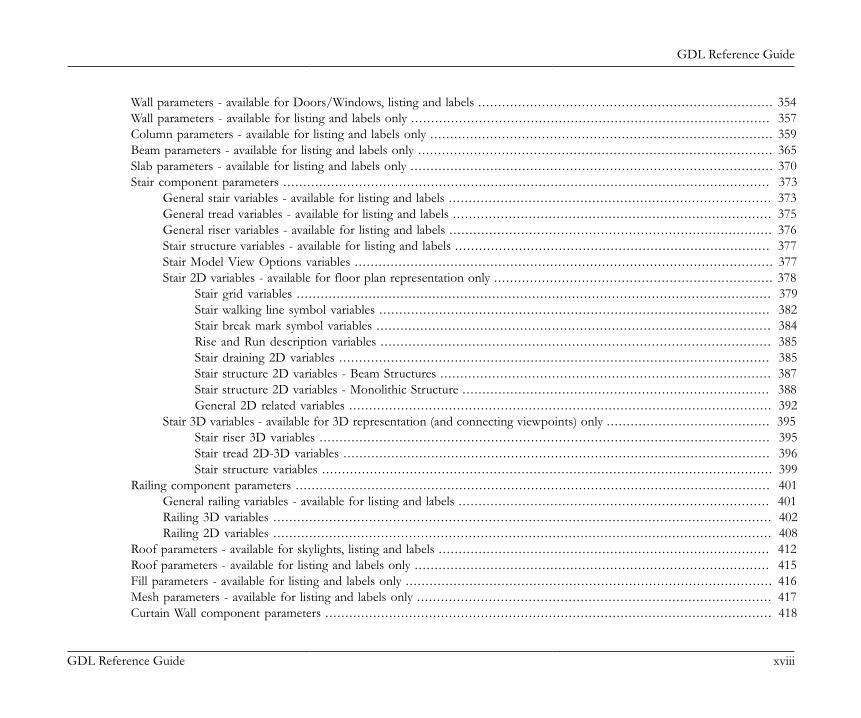
GDL Reference Guide
GDL Reference Guide xviii
Wall parameters - available for Doors/Windows, listing and labels . . . . . . . . . . . . . . . . . . . . . . . . . . . . . . . . . . . . . . . . . . . . . . . . . . . . . . . . . . . . . . . . . . . . . . . . . . 354Wall parameters - available for listing and labels only . . . . . . . . . . . . . . . . . . . . . . . . . . . . . . . . . . . . . . . . . . . . . . . . . . . . . . . . . . . . . . . . . . . . . . . . . . . . . . . . . . . . . . . . . . 357Column parameters - available for listing and labels only . . . . . . . . . . . . . . . . . . . . . . . . . . . . . . . . . . . . . . . . . . . . . . . . . . . . . . . . . . . . . . . . . . . . . . . . . . . . . . . . . . . . . . 359Beam parameters - available for listing and labels only . . . . . . . . . . . . . . . . . . . . . . . . . . . . . . . . . . . . . . . . . . . . . . . . . . . . . . . . . . . . . . . . . . . . . . . . . . . . . . . . . . . . . . . . . 365Slab parameters - available for listing and labels only . . . . . . . . . . . . . . . . . . . . . . . . . . . . . . . . . . . . . . . . . . . . . . . . . . . . . . . . . . . . . . . . . . . . . . . . . . . . . . . . . . . . . . . . . . . 370Stair component parameters . . . . . . . . . . . . . . . . . . . . . . . . . . . . . . . . . . . . . . . . . . . . . . . . . . . . . . . . . . . . . . . . . . . . . . . . . . . . . . . . . . . . . . . . . . . . . . . . . . . . . . . . . . . . . . . . . . . . . . . . . . 373
General stair variables - available for listing and labels . . . . . . . . . . . . . . . . . . . . . . . . . . . . . . . . . . . . . . . . . . . . . . . . . . . . . . . . . . . . . . . . . . . . . . . . . . . . . . . . . 373General tread variables - available for listing and labels . . . . . . . . . . . . . . . . . . . . . . . . . . . . . . . . . . . . . . . . . . . . . . . . . . . . . . . . . . . . . . . . . . . . . . . . . . . . . . . . 375General riser variables - available for listing and labels . . . . . . . . . . . . . . . . . . . . . . . . . . . . . . . . . . . . . . . . . . . . . . . . . . . . . . . . . . . . . . . . . . . . . . . . . . . . . . . . . 376Stair structure variables - available for listing and labels . . . . . . . . . . . . . . . . . . . . . . . . . . . . . . . . . . . . . . . . . . . . . . . . . . . . . . . . . . . . . . . . . . . . . . . . . . . . . . . 377Stair Model View Options variables . . . . . . . . . . . . . . . . . . . . . . . . . . . . . . . . . . . . . . . . . . . . . . . . . . . . . . . . . . . . . . . . . . . . . . . . . . . . . . . . . . . . . . . . . . . . . . . . . . . . . . . . . 377Stair 2D variables - available for floor plan representation only . . . . . . . . . . . . . . . . . . . . . . . . . . . . . . . . . . . . . . . . . . . . . . . . . . . . . . . . . . . . . . . . . . . . . . 378
Stair grid variables . . . . . . . . . . . . . . . . . . . . . . . . . . . . . . . . . . . . . . . . . . . . . . . . . . . . . . . . . . . . . . . . . . . . . . . . . . . . . . . . . . . . . . . . . . . . . . . . . . . . . . . . . . . . . . . . . . . . . . . 379Stair walking line symbol variables . . . . . . . . . . . . . . . . . . . . . . . . . . . . . . . . . . . . . . . . . . . . . . . . . . . . . . . . . . . . . . . . . . . . . . . . . . . . . . . . . . . . . . . . . . . . . . . . . . 382Stair break mark symbol variables . . . . . . . . . . . . . . . . . . . . . . . . . . . . . . . . . . . . . . . . . . . . . . . . . . . . . . . . . . . . . . . . . . . . . . . . . . . . . . . . . . . . . . . . . . . . . . . . . . . 384Rise and Run description variables . . . . . . . . . . . . . . . . . . . . . . . . . . . . . . . . . . . . . . . . . . . . . . . . . . . . . . . . . . . . . . . . . . . . . . . . . . . . . . . . . . . . . . . . . . . . . . . . . . 385Stair draining 2D variables . . . . . . . . . . . . . . . . . . . . . . . . . . . . . . . . . . . . . . . . . . . . . . . . . . . . . . . . . . . . . . . . . . . . . . . . . . . . . . . . . . . . . . . . . . . . . . . . . . . . . . . . . . . . 385Stair structure 2D variables - Beam Structures . . . . . . . . . . . . . . . . . . . . . . . . . . . . . . . . . . . . . . . . . . . . . . . . . . . . . . . . . . . . . . . . . . . . . . . . . . . . . . . . . . . 387Stair structure 2D variables - Monolithic Structure . . . . . . . . . . . . . . . . . . . . . . . . . . . . . . . . . . . . . . . . . . . . . . . . . . . . . . . . . . . . . . . . . . . . . . . . . . . . . 388General 2D related variables . . . . . . . . . . . . . . . . . . . . . . . . . . . . . . . . . . . . . . . . . . . . . . . . . . . . . . . . . . . . . . . . . . . . . . . . . . . . . . . . . . . . . . . . . . . . . . . . . . . . . . . . . . 392
Stair 3D variables - available for 3D representation (and connecting viewpoints) only . . . . . . . . . . . . . . . . . . . . . . . . . . . . . . . . . . . . . . . . . 395Stair riser 3D variables . . . . . . . . . . . . . . . . . . . . . . . . . . . . . . . . . . . . . . . . . . . . . . . . . . . . . . . . . . . . . . . . . . . . . . . . . . . . . . . . . . . . . . . . . . . . . . . . . . . . . . . . . . . . . . . . . 395Stair tread 2D-3D variables . . . . . . . . . . . . . . . . . . . . . . . . . . . . . . . . . . . . . . . . . . . . . . . . . . . . . . . . . . . . . . . . . . . . . . . . . . . . . . . . . . . . . . . . . . . . . . . . . . . . . . . . . . . 396Stair structure variables . . . . . . . . . . . . . . . . . . . . . . . . . . . . . . . . . . . . . . . . . . . . . . . . . . . . . . . . . . . . . . . . . . . . . . . . . . . . . . . . . . . . . . . . . . . . . . . . . . . . . . . . . . . . . . . . . 399
Railing component parameters . . . . . . . . . . . . . . . . . . . . . . . . . . . . . . . . . . . . . . . . . . . . . . . . . . . . . . . . . . . . . . . . . . . . . . . . . . . . . . . . . . . . . . . . . . . . . . . . . . . . . . . . . . . . . . . . . . . . . . . 401General railing variables - available for listing and labels . . . . . . . . . . . . . . . . . . . . . . . . . . . . . . . . . . . . . . . . . . . . . . . . . . . . . . . . . . . . . . . . . . . . . . . . . . . . . . 401Railing 3D variables . . . . . . . . . . . . . . . . . . . . . . . . . . . . . . . . . . . . . . . . . . . . . . . . . . . . . . . . . . . . . . . . . . . . . . . . . . . . . . . . . . . . . . . . . . . . . . . . . . . . . . . . . . . . . . . . . . . . . . . . . . . . . 402Railing 2D variables . . . . . . . . . . . . . . . . . . . . . . . . . . . . . . . . . . . . . . . . . . . . . . . . . . . . . . . . . . . . . . . . . . . . . . . . . . . . . . . . . . . . . . . . . . . . . . . . . . . . . . . . . . . . . . . . . . . . . . . . . . . . . 408
Roof parameters - available for skylights, listing and labels . . . . . . . . . . . . . . . . . . . . . . . . . . . . . . . . . . . . . . . . . . . . . . . . . . . . . . . . . . . . . . . . . . . . . . . . . . . . . . . . . . . 412Roof parameters - available for listing and labels only . . . . . . . . . . . . . . . . . . . . . . . . . . . . . . . . . . . . . . . . . . . . . . . . . . . . . . . . . . . . . . . . . . . . . . . . . . . . . . . . . . . . . . . . . 415Fill parameters - available for listing and labels only . . . . . . . . . . . . . . . . . . . . . . . . . . . . . . . . . . . . . . . . . . . . . . . . . . . . . . . . . . . . . . . . . . . . . . . . . . . . . . . . . . . . . . . . . . . . 416Mesh parameters - available for listing and labels only . . . . . . . . . . . . . . . . . . . . . . . . . . . . . . . . . . . . . . . . . . . . . . . . . . . . . . . . . . . . . . . . . . . . . . . . . . . . . . . . . . . . . . . . . 417Curtain Wall component parameters . . . . . . . . . . . . . . . . . . . . . . . . . . . . . . . . . . . . . . . . . . . . . . . . . . . . . . . . . . . . . . . . . . . . . . . . . . . . . . . . . . . . . . . . . . . . . . . . . . . . . . . . . . . . . . . . 418
GDL Reference Guide
GDL Reference Guide xix
Curtain Wall parameters - available for listing and labels only . . . . . . . . . . . . . . . . . . . . . . . . . . . . . . . . . . . . . . . . . . . . . . . . . . . . . . . . . . . . . . . . . . . . . . . . . . . . . . . . 420Curtain Wall Frame parameters . . . . . . . . . . . . . . . . . . . . . . . . . . . . . . . . . . . . . . . . . . . . . . . . . . . . . . . . . . . . . . . . . . . . . . . . . . . . . . . . . . . . . . . . . . . . . . . . . . . . . . . . . . . . . . . . . . . . . . 421
General Curtain Wall Frame variables - available for listing and labels only . . . . . . . . . . . . . . . . . . . . . . . . . . . . . . . . . . . . . . . . . . . . . . . . . . . . . . . 421Curtain Wall Frame 3D variables . . . . . . . . . . . . . . . . . . . . . . . . . . . . . . . . . . . . . . . . . . . . . . . . . . . . . . . . . . . . . . . . . . . . . . . . . . . . . . . . . . . . . . . . . . . . . . . . . . . . . . . . . . . . 421
Curtain Wall Panel variables . . . . . . . . . . . . . . . . . . . . . . . . . . . . . . . . . . . . . . . . . . . . . . . . . . . . . . . . . . . . . . . . . . . . . . . . . . . . . . . . . . . . . . . . . . . . . . . . . . . . . . . . . . . . . . . . . . . . . . . . . . . 423Curtain Wall Panel parameters - available for listing and labels only . . . . . . . . . . . . . . . . . . . . . . . . . . . . . . . . . . . . . . . . . . . . . . . . . . . . . . . . . . . . . . . . . . . . . . . . 424Curtain Wall Junction parameters - available for listing and labels only . . . . . . . . . . . . . . . . . . . . . . . . . . . . . . . . . . . . . . . . . . . . . . . . . . . . . . . . . . . . . . . . . . . . 424Curtain Wall Accessory parameters - available for listing and labels only . . . . . . . . . . . . . . . . . . . . . . . . . . . . . . . . . . . . . . . . . . . . . . . . . . . . . . . . . . . . . . . . . . 425Migration parameters - available for migration scripts only . . . . . . . . . . . . . . . . . . . . . . . . . . . . . . . . . . . . . . . . . . . . . . . . . . . . . . . . . . . . . . . . . . . . . . . . . . . . . . . . . . . 425Skylight parameters - available for listing and labels only . . . . . . . . . . . . . . . . . . . . . . . . . . . . . . . . . . . . . . . . . . . . . . . . . . . . . . . . . . . . . . . . . . . . . . . . . . . . . . . . . . . . . . 425Common Parameters for Shells and Roofs - available for listing and labels only . . . . . . . . . . . . . . . . . . . . . . . . . . . . . . . . . . . . . . . . . . . . . . . . . . . . . . . . . 425Parameters for Morphs - available for listing and labels only . . . . . . . . . . . . . . . . . . . . . . . . . . . . . . . . . . . . . . . . . . . . . . . . . . . . . . . . . . . . . . . . . . . . . . . . . . . . . . . . . 430Free users’ globals . . . . . . . . . . . . . . . . . . . . . . . . . . . . . . . . . . . . . . . . . . . . . . . . . . . . . . . . . . . . . . . . . . . . . . . . . . . . . . . . . . . . . . . . . . . . . . . . . . . . . . . . . . . . . . . . . . . . . . . . . . . . . . . . . . . . . . . 431Example usage of global variables . . . . . . . . . . . . . . . . . . . . . . . . . . . . . . . . . . . . . . . . . . . . . . . . . . . . . . . . . . . . . . . . . . . . . . . . . . . . . . . . . . . . . . . . . . . . . . . . . . . . . . . . . . . . . . . . . . . 432Deprecated Global Variables . . . . . . . . . . . . . . . . . . . . . . . . . . . . . . . . . . . . . . . . . . . . . . . . . . . . . . . . . . . . . . . . . . . . . . . . . . . . . . . . . . . . . . . . . . . . . . . . . . . . . . . . . . . . . . . . . . . . . . . . . . 432Deprecated Beam/Column Global Variables - available for listing and labels only . . . . . . . . . . . . . . . . . . . . . . . . . . . . . . . . . . . . . . . . . . . . . . . . . . . . . . 433Deprecated Label Global Variables . . . . . . . . . . . . . . . . . . . . . . . . . . . . . . . . . . . . . . . . . . . . . . . . . . . . . . . . . . . . . . . . . . . . . . . . . . . . . . . . . . . . . . . . . . . . . . . . . . . . . . . . . . . . . . . . . . 433Deprecated Curtain Wall Frame Global Variable - available for listing and labels only . . . . . . . . . . . . . . . . . . . . . . . . . . . . . . . . . . . . . . . . . . . . . . . . . 435Old Global Variables . . . . . . . . . . . . . . . . . . . . . . . . . . . . . . . . . . . . . . . . . . . . . . . . . . . . . . . . . . . . . . . . . . . . . . . . . . . . . . . . . . . . . . . . . . . . . . . . . . . . . . . . . . . . . . . . . . . . . . . . . . . . . . . . . . . . 435
Fix named optional parameters . . . . . . . . . . . . . . . . . . . . . . . . . . . . . . . . . . . . . . . . . . . . . . . . . . . . . . . . . . . . . . . . . . . . . . . . . . . . . . . . . . . . . . . . . . . . . . . . . . . . . . . . . . . . . . . . . . . . . . . . . . . . . . 437Parameters set by ARCHICAD .. . . . . . . . . . . . . . . . . . . . . . . . . . . . . . . . . . . . . . . . . . . . . . . . . . . . . . . . . . . . . . . . . . . . . . . . . . . . . . . . . . . . . . . . . . . . . . . . . . . . . . . . . . . . . . . . . . . . . 437
Parameters for D/W attributes (available for Door, Window, Label, Listing) . . . . . . . . . . . . . . . . . . . . . . . . . . . . . . . . . . . . . . . . . . . . . . . . . . . . . 438Floor plan display . . . . . . . . . . . . . . . . . . . . . . . . . . . . . . . . . . . . . . . . . . . . . . . . . . . . . . . . . . . . . . . . . . . . . . . . . . . . . . . . . . . . . . . . . . . . . . . . . . . . . . . . . . . . . . . . . . . . . . . . 438Direction . . . . . . . . . . . . . . . . . . . . . . . . . . . . . . . . . . . . . . . . . . . . . . . . . . . . . . . . . . . . . . . . . . . . . . . . . . . . . . . . . . . . . . . . . . . . . . . . . . . . . . . . . . . . . . . . . . . . . . . . . . . . . . . . . . . 438Polygonal wall data . . . . . . . . . . . . . . . . . . . . . . . . . . . . . . . . . . . . . . . . . . . . . . . . . . . . . . . . . . . . . . . . . . . . . . . . . . . . . . . . . . . . . . . . . . . . . . . . . . . . . . . . . . . . . . . . . . . . . . 439Hole position . . . . . . . . . . . . . . . . . . . . . . . . . . . . . . . . . . . . . . . . . . . . . . . . . . . . . . . . . . . . . . . . . . . . . . . . . . . . . . . . . . . . . . . . . . . . . . . . . . . . . . . . . . . . . . . . . . . . . . . . . . . . . 439Anchor data . . . . . . . . . . . . . . . . . . . . . . . . . . . . . . . . . . . . . . . . . . . . . . . . . . . . . . . . . . . . . . . . . . . . . . . . . . . . . . . . . . . . . . . . . . . . . . . . . . . . . . . . . . . . . . . . . . . . . . . . . . . . . . . 439
Parameters for WALL attributes (available for Door, Window, Label, Listing) . . . . . . . . . . . . . . . . . . . . . . . . . . . . . . . . . . . . . . . . . . . . . . . . . . . 439Floor plan display . . . . . . . . . . . . . . . . . . . . . . . . . . . . . . . . . . . . . . . . . . . . . . . . . . . . . . . . . . . . . . . . . . . . . . . . . . . . . . . . . . . . . . . . . . . . . . . . . . . . . . . . . . . . . . . . . . . . . . . . 439Geometric data . . . . . . . . . . . . . . . . . . . . . . . . . . . . . . . . . . . . . . . . . . . . . . . . . . . . . . . . . . . . . . . . . . . . . . . . . . . . . . . . . . . . . . . . . . . . . . . . . . . . . . . . . . . . . . . . . . . . . . . . . . . 440
Parameters for COLUMN attributes (available for Label, Listing) . . . . . . . . . . . . . . . . . . . . . . . . . . . . . . . . . . . . . . . . . . . . . . . . . . . . . . . . . . . . . . . . . . . 440Floor plan display . . . . . . . . . . . . . . . . . . . . . . . . . . . . . . . . . . . . . . . . . . . . . . . . . . . . . . . . . . . . . . . . . . . . . . . . . . . . . . . . . . . . . . . . . . . . . . . . . . . . . . . . . . . . . . . . . . . . . . . . 441Geometric data . . . . . . . . . . . . . . . . . . . . . . . . . . . . . . . . . . . . . . . . . . . . . . . . . . . . . . . . . . . . . . . . . . . . . . . . . . . . . . . . . . . . . . . . . . . . . . . . . . . . . . . . . . . . . . . . . . . . . . . . . . . 442
GDL Reference Guide
GDL Reference Guide xx
Parameters for BEAM attributes (available for Label, Listing) . . . . . . . . . . . . . . . . . . . . . . . . . . . . . . . . . . . . . . . . . . . . . . . . . . . . . . . . . . . . . . . . . . . . . . . . 442Floor plan display . . . . . . . . . . . . . . . . . . . . . . . . . . . . . . . . . . . . . . . . . . . . . . . . . . . . . . . . . . . . . . . . . . . . . . . . . . . . . . . . . . . . . . . . . . . . . . . . . . . . . . . . . . . . . . . . . . . . . . . . 442Geometric data . . . . . . . . . . . . . . . . . . . . . . . . . . . . . . . . . . . . . . . . . . . . . . . . . . . . . . . . . . . . . . . . . . . . . . . . . . . . . . . . . . . . . . . . . . . . . . . . . . . . . . . . . . . . . . . . . . . . . . . . . . . 443
Parameters for ROOF attributes (available for Label, Listing) . . . . . . . . . . . . . . . . . . . . . . . . . . . . . . . . . . . . . . . . . . . . . . . . . . . . . . . . . . . . . . . . . . . . . . . . 444Floor plan display . . . . . . . . . . . . . . . . . . . . . . . . . . . . . . . . . . . . . . . . . . . . . . . . . . . . . . . . . . . . . . . . . . . . . . . . . . . . . . . . . . . . . . . . . . . . . . . . . . . . . . . . . . . . . . . . . . . . . . . . 444
Door/Window Marker attributes . . . . . . . . . . . . . . . . . . . . . . . . . . . . . . . . . . . . . . . . . . . . . . . . . . . . . . . . . . . . . . . . . . . . . . . . . . . . . . . . . . . . . . . . . . . . . . . . . . . . . . . . . . . . 444Detail/Worksheet Marker attributes . . . . . . . . . . . . . . . . . . . . . . . . . . . . . . . . . . . . . . . . . . . . . . . . . . . . . . . . . . . . . . . . . . . . . . . . . . . . . . . . . . . . . . . . . . . . . . . . . . . . . . . . . 446Drawing Title attributes . . . . . . . . . . . . . . . . . . . . . . . . . . . . . . . . . . . . . . . . . . . . . . . . . . . . . . . . . . . . . . . . . . . . . . . . . . . . . . . . . . . . . . . . . . . . . . . . . . . . . . . . . . . . . . . . . . . . . . . . 446General running context . . . . . . . . . . . . . . . . . . . . . . . . . . . . . . . . . . . . . . . . . . . . . . . . . . . . . . . . . . . . . . . . . . . . . . . . . . . . . . . . . . . . . . . . . . . . . . . . . . . . . . . . . . . . . . . . . . . . . . . 447Room parameters (available for Zone Stamps) . . . . . . . . . . . . . . . . . . . . . . . . . . . . . . . . . . . . . . . . . . . . . . . . . . . . . . . . . . . . . . . . . . . . . . . . . . . . . . . . . . . . . . . . . . . 448Stair related parameters . . . . . . . . . . . . . . . . . . . . . . . . . . . . . . . . . . . . . . . . . . . . . . . . . . . . . . . . . . . . . . . . . . . . . . . . . . . . . . . . . . . . . . . . . . . . . . . . . . . . . . . . . . . . . . . . . . . . . . . . . 450
Flight / Landing Side Supported subtypes . . . . . . . . . . . . . . . . . . . . . . . . . . . . . . . . . . . . . . . . . . . . . . . . . . . . . . . . . . . . . . . . . . . . . . . . . . . . . . . . . . . . . . . . 450Riser Component subtype . . . . . . . . . . . . . . . . . . . . . . . . . . . . . . . . . . . . . . . . . . . . . . . . . . . . . . . . . . . . . . . . . . . . . . . . . . . . . . . . . . . . . . . . . . . . . . . . . . . . . . . . . . . . . 450Stair 2D Component subtypes . . . . . . . . . . . . . . . . . . . . . . . . . . . . . . . . . . . . . . . . . . . . . . . . . . . . . . . . . . . . . . . . . . . . . . . . . . . . . . . . . . . . . . . . . . . . . . . . . . . . . . . 450
Parameters set/read by ARCHICAD .. . . . . . . . . . . . . . . . . . . . . . . . . . . . . . . . . . . . . . . . . . . . . . . . . . . . . . . . . . . . . . . . . . . . . . . . . . . . . . . . . . . . . . . . . . . . . . . . . . . . . . . . . . . . . . 450Stair related parameters . . . . . . . . . . . . . . . . . . . . . . . . . . . . . . . . . . . . . . . . . . . . . . . . . . . . . . . . . . . . . . . . . . . . . . . . . . . . . . . . . . . . . . . . . . . . . . . . . . . . . . . . . . . . . . . . . . . . . . . . . 450
Structure subtype . . . . . . . . . . . . . . . . . . . . . . . . . . . . . . . . . . . . . . . . . . . . . . . . . . . . . . . . . . . . . . . . . . . . . . . . . . . . . . . . . . . . . . . . . . . . . . . . . . . . . . . . . . . . . . . . . . . . . . . . 450Parameters read by ARCHICAD .. . . . . . . . . . . . . . . . . . . . . . . . . . . . . . . . . . . . . . . . . . . . . . . . . . . . . . . . . . . . . . . . . . . . . . . . . . . . . . . . . . . . . . . . . . . . . . . . . . . . . . . . . . . . . . . . . . . 451
Objects on Floor Plan . . . . . . . . . . . . . . . . . . . . . . . . . . . . . . . . . . . . . . . . . . . . . . . . . . . . . . . . . . . . . . . . . . . . . . . . . . . . . . . . . . . . . . . . . . . . . . . . . . . . . . . . . . . . . . . . . . . . . . . . . . 451Floor plan cutting of planar elements (i.e. skylight object, roof accessory objects) . . . . . . . . . . . . . . . . . . . . . . . . . . . . . . . . . . . . . . . 451
Door/Window objects . . . . . . . . . . . . . . . . . . . . . . . . . . . . . . . . . . . . . . . . . . . . . . . . . . . . . . . . . . . . . . . . . . . . . . . . . . . . . . . . . . . . . . . . . . . . . . . . . . . . . . . . . . . . . . . . . . . . . . . . . . 452Custom Component Template . . . . . . . . . . . . . . . . . . . . . . . . . . . . . . . . . . . . . . . . . . . . . . . . . . . . . . . . . . . . . . . . . . . . . . . . . . . . . . . . . . . . . . . . . . . . . . . . . . . . . . . . . . . . . . . . 453Stair related parameters . . . . . . . . . . . . . . . . . . . . . . . . . . . . . . . . . . . . . . . . . . . . . . . . . . . . . . . . . . . . . . . . . . . . . . . . . . . . . . . . . . . . . . . . . . . . . . . . . . . . . . . . . . . . . . . . . . . . . . . . . 453
Structure subtype . . . . . . . . . . . . . . . . . . . . . . . . . . . . . . . . . . . . . . . . . . . . . . . . . . . . . . . . . . . . . . . . . . . . . . . . . . . . . . . . . . . . . . . . . . . . . . . . . . . . . . . . . . . . . . . . . . . . . . . . 453Flight / Landing Under Supported subtype . . . . . . . . . . . . . . . . . . . . . . . . . . . . . . . . . . . . . . . . . . . . . . . . . . . . . . . . . . . . . . . . . . . . . . . . . . . . . . . . . . . . . . . 453Flight Under Supported Cantilever / Landing Cantilever Supported subtypes . . . . . . . . . . . . . . . . . . . . . . . . . . . . . . . . . . . . . . . . . . . . 454
Railing related parameters . . . . . . . . . . . . . . . . . . . . . . . . . . . . . . . . . . . . . . . . . . . . . . . . . . . . . . . . . . . . . . . . . . . . . . . . . . . . . . . . . . . . . . . . . . . . . . . . . . . . . . . . . . . . . . . . . . . . . . 454Railing Panel Component subtype . . . . . . . . . . . . . . . . . . . . . . . . . . . . . . . . . . . . . . . . . . . . . . . . . . . . . . . . . . . . . . . . . . . . . . . . . . . . . . . . . . . . . . . . . . . . . . . . . . . 454Railing Rail Component subtype . . . . . . . . . . . . . . . . . . . . . . . . . . . . . . . . . . . . . . . . . . . . . . . . . . . . . . . . . . . . . . . . . . . . . . . . . . . . . . . . . . . . . . . . . . . . . . . . . . . . . 454Railing Post Component subtype . . . . . . . . . . . . . . . . . . . . . . . . . . . . . . . . . . . . . . . . . . . . . . . . . . . . . . . . . . . . . . . . . . . . . . . . . . . . . . . . . . . . . . . . . . . . . . . . . . . . 455Railing End Component subtype . . . . . . . . . . . . . . . . . . . . . . . . . . . . . . . . . . . . . . . . . . . . . . . . . . . . . . . . . . . . . . . . . . . . . . . . . . . . . . . . . . . . . . . . . . . . . . . . . . . . 456
Parameters for Curtain Wall . . . . . . . . . . . . . . . . . . . . . . . . . . . . . . . . . . . . . . . . . . . . . . . . . . . . . . . . . . . . . . . . . . . . . . . . . . . . . . . . . . . . . . . . . . . . . . . . . . . . . . . . . . . . . . . . . . . . . . . . . . . 456Curtain Wall Parameters set and read by ARCHICAD .. . . . . . . . . . . . . . . . . . . . . . . . . . . . . . . . . . . . . . . . . . . . . . . . . . . . . . . . . . . . . . . . . . . . . . . . . . . . . . . . 457

GDL Reference Guide
GDL Reference Guide xxi
Curtain Wall Frame parameters . . . . . . . . . . . . . . . . . . . . . . . . . . . . . . . . . . . . . . . . . . . . . . . . . . . . . . . . . . . . . . . . . . . . . . . . . . . . . . . . . . . . . . . . . . . . . . . . . . . . . . 457Curtain Wall Parameters set by ARCHICAD .. . . . . . . . . . . . . . . . . . . . . . . . . . . . . . . . . . . . . . . . . . . . . . . . . . . . . . . . . . . . . . . . . . . . . . . . . . . . . . . . . . . . . . . . . . . . 457
Curtain Wall Frame parameters . . . . . . . . . . . . . . . . . . . . . . . . . . . . . . . . . . . . . . . . . . . . . . . . . . . . . . . . . . . . . . . . . . . . . . . . . . . . . . . . . . . . . . . . . . . . . . . . . . . . . . 457Curtain Wall Panel parameters . . . . . . . . . . . . . . . . . . . . . . . . . . . . . . . . . . . . . . . . . . . . . . . . . . . . . . . . . . . . . . . . . . . . . . . . . . . . . . . . . . . . . . . . . . . . . . . . . . . . . . . . 458Curtain Wall Junction parameters . . . . . . . . . . . . . . . . . . . . . . . . . . . . . . . . . . . . . . . . . . . . . . . . . . . . . . . . . . . . . . . . . . . . . . . . . . . . . . . . . . . . . . . . . . . . . . . . . . . . 458Curtain Wall Accessory parameters . . . . . . . . . . . . . . . . . . . . . . . . . . . . . . . . . . . . . . . . . . . . . . . . . . . . . . . . . . . . . . . . . . . . . . . . . . . . . . . . . . . . . . . . . . . . . . . . . . 458Curtain Wall Frame Deprecated parameters . . . . . . . . . . . . . . . . . . . . . . . . . . . . . . . . . . . . . . . . . . . . . . . . . . . . . . . . . . . . . . . . . . . . . . . . . . . . . . . . . . . . . . . 459
Curtain Wall Parameters read by ARCHICAD .. . . . . . . . . . . . . . . . . . . . . . . . . . . . . . . . . . . . . . . . . . . . . . . . . . . . . . . . . . . . . . . . . . . . . . . . . . . . . . . . . . . . . . . . . . 460Curtain Wall Panel and Frame parameters . . . . . . . . . . . . . . . . . . . . . . . . . . . . . . . . . . . . . . . . . . . . . . . . . . . . . . . . . . . . . . . . . . . . . . . . . . . . . . . . . . . . . . . . . 460Curtain Wall Frame parameters . . . . . . . . . . . . . . . . . . . . . . . . . . . . . . . . . . . . . . . . . . . . . . . . . . . . . . . . . . . . . . . . . . . . . . . . . . . . . . . . . . . . . . . . . . . . . . . . . . . . . . 461Curtain wall panel parameters . . . . . . . . . . . . . . . . . . . . . . . . . . . . . . . . . . . . . . . . . . . . . . . . . . . . . . . . . . . . . . . . . . . . . . . . . . . . . . . . . . . . . . . . . . . . . . . . . . . . . . . . 462
Parameters for add-ons . . . . . . . . . . . . . . . . . . . . . . . . . . . . . . . . . . . . . . . . . . . . . . . . . . . . . . . . . . . . . . . . . . . . . . . . . . . . . . . . . . . . . . . . . . . . . . . . . . . . . . . . . . . . . . . . . . . . . . . . . . . . . . . . . 463Parameters of Skylight add-on . . . . . . . . . . . . . . . . . . . . . . . . . . . . . . . . . . . . . . . . . . . . . . . . . . . . . . . . . . . . . . . . . . . . . . . . . . . . . . . . . . . . . . . . . . . . . . . . . . . . . . . . . . . . . . . . 463
Hole edge cut manipulation . . . . . . . . . . . . . . . . . . . . . . . . . . . . . . . . . . . . . . . . . . . . . . . . . . . . . . . . . . . . . . . . . . . . . . . . . . . . . . . . . . . . . . . . . . . . . . . . . . . . . . . . . . . 463Parameters of Corner Window add-on . . . . . . . . . . . . . . . . . . . . . . . . . . . . . . . . . . . . . . . . . . . . . . . . . . . . . . . . . . . . . . . . . . . . . . . . . . . . . . . . . . . . . . . . . . . . . . . . . . . . . 463
Basic parameters of Corner Window objects . . . . . . . . . . . . . . . . . . . . . . . . . . . . . . . . . . . . . . . . . . . . . . . . . . . . . . . . . . . . . . . . . . . . . . . . . . . . . . . . . . . . . 463Wall skins data parameters of Corner Window objects (available from ARCHICAD 12) . . . . . . . . . . . . . . . . . . . . . . . . . . . . . . 464
Parameters of IFC add-on . . . . . . . . . . . . . . . . . . . . . . . . . . . . . . . . . . . . . . . . . . . . . . . . . . . . . . . . . . . . . . . . . . . . . . . . . . . . . . . . . . . . . . . . . . . . . . . . . . . . . . . . . . . . . . . . . . . . . 464Common basic parameters of Door and Window objects . . . . . . . . . . . . . . . . . . . . . . . . . . . . . . . . . . . . . . . . . . . . . . . . . . . . . . . . . . . . . . . . . . . . . 464Basic parameters of Door objects . . . . . . . . . . . . . . . . . . . . . . . . . . . . . . . . . . . . . . . . . . . . . . . . . . . . . . . . . . . . . . . . . . . . . . . . . . . . . . . . . . . . . . . . . . . . . . . . . . . 466Basic parameters of Window objects . . . . . . . . . . . . . . . . . . . . . . . . . . . . . . . . . . . . . . . . . . . . . . . . . . . . . . . . . . . . . . . . . . . . . . . . . . . . . . . . . . . . . . . . . . . . . . . 469Basic parameters of Transport Elements . . . . . . . . . . . . . . . . . . . . . . . . . . . . . . . . . . . . . . . . . . . . . . . . . . . . . . . . . . . . . . . . . . . . . . . . . . . . . . . . . . . . . . . . . . . 472Basic parameters of Lift objects . . . . . . . . . . . . . . . . . . . . . . . . . . . . . . . . . . . . . . . . . . . . . . . . . . . . . . . . . . . . . . . . . . . . . . . . . . . . . . . . . . . . . . . . . . . . . . . . . . . . . . 472Basic parameters of Stair objects . . . . . . . . . . . . . . . . . . . . . . . . . . . . . . . . . . . . . . . . . . . . . . . . . . . . . . . . . . . . . . . . . . . . . . . . . . . . . . . . . . . . . . . . . . . . . . . . . . . . 473Basic parameters of MEP elements . . . . . . . . . . . . . . . . . . . . . . . . . . . . . . . . . . . . . . . . . . . . . . . . . . . . . . . . . . . . . . . . . . . . . . . . . . . . . . . . . . . . . . . . . . . . . . . . . 475
Parameters for Text Handling . . . . . . . . . . . . . . . . . . . . . . . . . . . . . . . . . . . . . . . . . . . . . . . . . . . . . . . . . . . . . . . . . . . . . . . . . . . . . . . . . . . . . . . . . . . . . . . . . . . . . . . . . . . . . . . . . . . . . . . . 476Parameters for Labels . . . . . . . . . . . . . . . . . . . . . . . . . . . . . . . . . . . . . . . . . . . . . . . . . . . . . . . . . . . . . . . . . . . . . . . . . . . . . . . . . . . . . . . . . . . . . . . . . . . . . . . . . . . . . . . . . . . . . . . . . . . . . . . . . . . 477
Parameters set or read by ARCHICAD .. . . . . . . . . . . . . . . . . . . . . . . . . . . . . . . . . . . . . . . . . . . . . . . . . . . . . . . . . . . . . . . . . . . . . . . . . . . . . . . . . . . . . . . . . . . . . . . . . . . 477Parameters read by ARCHICAD .. . . . . . . . . . . . . . . . . . . . . . . . . . . . . . . . . . . . . . . . . . . . . . . . . . . . . . . . . . . . . . . . . . . . . . . . . . . . . . . . . . . . . . . . . . . . . . . . . . . . . . . . . . . 479
Deprecated parameters . . . . . . . . . . . . . . . . . . . . . . . . . . . . . . . . . . . . . . . . . . . . . . . . . . . . . . . . . . . . . . . . . . . . . . . . . . . . . . . . . . . . . . . . . . . . . . . . . . . . . . . . . . . . . . . . . . . . . . . . . . . . . . . . . 480Deprecated Beam/Column parameters - available for listing and labels only . . . . . . . . . . . . . . . . . . . . . . . . . . . . . . . . . . . . . . . . . . . . . . . . . . . . . 480Deprecated Zone Stamp parameters . . . . . . . . . . . . . . . . . . . . . . . . . . . . . . . . . . . . . . . . . . . . . . . . . . . . . . . . . . . . . . . . . . . . . . . . . . . . . . . . . . . . . . . . . . . . . . . . . . . . . . . . 481
REQUEST Options . . . . . . . . . . . . . . . . . . . . . . . . . . . . . . . . . . . . . . . . . . . . . . . . . . . . . . . . . . . . . . . . . . . . . . . . . . . . . . . . . . . . . . . . . . . . . . . . . . . . . . . . . . . . . . . . . . . . . . . . . . . . . . . . . . . . . . . . . . . . . 481

GDL Reference Guide
GDL Reference Guide xxii
Request Parameter Script Compatibility . . . . . . . . . . . . . . . . . . . . . . . . . . . . . . . . . . . . . . . . . . . . . . . . . . . . . . . . . . . . . . . . . . . . . . . . . . . . . . . . . . . . . . . . . . . . . . . . . . . . . . . . . . . . 481Details of Requests . . . . . . . . . . . . . . . . . . . . . . . . . . . . . . . . . . . . . . . . . . . . . . . . . . . . . . . . . . . . . . . . . . . . . . . . . . . . . . . . . . . . . . . . . . . . . . . . . . . . . . . . . . . . . . . . . . . . . . . . . . . . . . . . . . . . . 487Profile Requests . . . . . . . . . . . . . . . . . . . . . . . . . . . . . . . . . . . . . . . . . . . . . . . . . . . . . . . . . . . . . . . . . . . . . . . . . . . . . . . . . . . . . . . . . . . . . . . . . . . . . . . . . . . . . . . . . . . . . . . . . . . . . . . . . . . . . . . . . . 509Deprecated Requests . . . . . . . . . . . . . . . . . . . . . . . . . . . . . . . . . . . . . . . . . . . . . . . . . . . . . . . . . . . . . . . . . . . . . . . . . . . . . . . . . . . . . . . . . . . . . . . . . . . . . . . . . . . . . . . . . . . . . . . . . . . . . . . . . . . . 512
Application Query Options . . . . . . . . . . . . . . . . . . . . . . . . . . . . . . . . . . . . . . . . . . . . . . . . . . . . . . . . . . . . . . . . . . . . . . . . . . . . . . . . . . . . . . . . . . . . . . . . . . . . . . . . . . . . . . . . . . . . . . . . . . . . . . . . . . . 512Document feature . . . . . . . . . . . . . . . . . . . . . . . . . . . . . . . . . . . . . . . . . . . . . . . . . . . . . . . . . . . . . . . . . . . . . . . . . . . . . . . . . . . . . . . . . . . . . . . . . . . . . . . . . . . . . . . . . . . . . . . . . . . . . . . . . . . . . . . . 513
View direction . . . . . . . . . . . . . . . . . . . . . . . . . . . . . . . . . . . . . . . . . . . . . . . . . . . . . . . . . . . . . . . . . . . . . . . . . . . . . . . . . . . . . . . . . . . . . . . . . . . . . . . . . . . . . . . . . . . . . . . . . . . . . . . . . . . . 513MEP System . . . . . . . . . . . . . . . . . . . . . . . . . . . . . . . . . . . . . . . . . . . . . . . . . . . . . . . . . . . . . . . . . . . . . . . . . . . . . . . . . . . . . . . . . . . . . . . . . . . . . . . . . . . . . . . . . . . . . . . . . . . . . . . . . . . . . . . . . . . . . . 513
Get MEP Systems . . . . . . . . . . . . . . . . . . . . . . . . . . . . . . . . . . . . . . . . . . . . . . . . . . . . . . . . . . . . . . . . . . . . . . . . . . . . . . . . . . . . . . . . . . . . . . . . . . . . . . . . . . . . . . . . . . . . . . . . . . . . . . . 513Get Domain . . . . . . . . . . . . . . . . . . . . . . . . . . . . . . . . . . . . . . . . . . . . . . . . . . . . . . . . . . . . . . . . . . . . . . . . . . . . . . . . . . . . . . . . . . . . . . . . . . . . . . . . . . . . . . . . . . . . . . . . . . . . . . . . . . . . . . . 513Get Contour Pen . . . . . . . . . . . . . . . . . . . . . . . . . . . . . . . . . . . . . . . . . . . . . . . . . . . . . . . . . . . . . . . . . . . . . . . . . . . . . . . . . . . . . . . . . . . . . . . . . . . . . . . . . . . . . . . . . . . . . . . . . . . . . . . . 514Get Fill Pen . . . . . . . . . . . . . . . . . . . . . . . . . . . . . . . . . . . . . . . . . . . . . . . . . . . . . . . . . . . . . . . . . . . . . . . . . . . . . . . . . . . . . . . . . . . . . . . . . . . . . . . . . . . . . . . . . . . . . . . . . . . . . . . . . . . . . . . 514Get Background Pen . . . . . . . . . . . . . . . . . . . . . . . . . . . . . . . . . . . . . . . . . . . . . . . . . . . . . . . . . . . . . . . . . . . . . . . . . . . . . . . . . . . . . . . . . . . . . . . . . . . . . . . . . . . . . . . . . . . . . . . . . . . . 514Get Fill Type . . . . . . . . . . . . . . . . . . . . . . . . . . . . . . . . . . . . . . . . . . . . . . . . . . . . . . . . . . . . . . . . . . . . . . . . . . . . . . . . . . . . . . . . . . . . . . . . . . . . . . . . . . . . . . . . . . . . . . . . . . . . . . . . . . . . . . 514Get Center Line Type . . . . . . . . . . . . . . . . . . . . . . . . . . . . . . . . . . . . . . . . . . . . . . . . . . . . . . . . . . . . . . . . . . . . . . . . . . . . . . . . . . . . . . . . . . . . . . . . . . . . . . . . . . . . . . . . . . . . . . . . . . 515Get Center Line Pen . . . . . . . . . . . . . . . . . . . . . . . . . . . . . . . . . . . . . . . . . . . . . . . . . . . . . . . . . . . . . . . . . . . . . . . . . . . . . . . . . . . . . . . . . . . . . . . . . . . . . . . . . . . . . . . . . . . . . . . . . . . . 515Get System Material . . . . . . . . . . . . . . . . . . . . . . . . . . . . . . . . . . . . . . . . . . . . . . . . . . . . . . . . . . . . . . . . . . . . . . . . . . . . . . . . . . . . . . . . . . . . . . . . . . . . . . . . . . . . . . . . . . . . . . . . . . . . . 515Get Insulation Material . . . . . . . . . . . . . . . . . . . . . . . . . . . . . . . . . . . . . . . . . . . . . . . . . . . . . . . . . . . . . . . . . . . . . . . . . . . . . . . . . . . . . . . . . . . . . . . . . . . . . . . . . . . . . . . . . . . . . . . . . 515
MEP Modeler . . . . . . . . . . . . . . . . . . . . . . . . . . . . . . . . . . . . . . . . . . . . . . . . . . . . . . . . . . . . . . . . . . . . . . . . . . . . . . . . . . . . . . . . . . . . . . . . . . . . . . . . . . . . . . . . . . . . . . . . . . . . . . . . . . . . . . . . . . . . . 516Is Available . . . . . . . . . . . . . . . . . . . . . . . . . . . . . . . . . . . . . . . . . . . . . . . . . . . . . . . . . . . . . . . . . . . . . . . . . . . . . . . . . . . . . . . . . . . . . . . . . . . . . . . . . . . . . . . . . . . . . . . . . . . . . . . . . . . . . . . . 516
MEP Connection Type . . . . . . . . . . . . . . . . . . . . . . . . . . . . . . . . . . . . . . . . . . . . . . . . . . . . . . . . . . . . . . . . . . . . . . . . . . . . . . . . . . . . . . . . . . . . . . . . . . . . . . . . . . . . . . . . . . . . . . . . . . . . . . . . . 516Get Connection Types . . . . . . . . . . . . . . . . . . . . . . . . . . . . . . . . . . . . . . . . . . . . . . . . . . . . . . . . . . . . . . . . . . . . . . . . . . . . . . . . . . . . . . . . . . . . . . . . . . . . . . . . . . . . . . . . . . . . . . . . . . 516Get Connection Type Style . . . . . . . . . . . . . . . . . . . . . . . . . . . . . . . . . . . . . . . . . . . . . . . . . . . . . . . . . . . . . . . . . . . . . . . . . . . . . . . . . . . . . . . . . . . . . . . . . . . . . . . . . . . . . . . . . . . . 516
MEP Flexible Segment . . . . . . . . . . . . . . . . . . . . . . . . . . . . . . . . . . . . . . . . . . . . . . . . . . . . . . . . . . . . . . . . . . . . . . . . . . . . . . . . . . . . . . . . . . . . . . . . . . . . . . . . . . . . . . . . . . . . . . . . . . . . . . . . . 517Start Sectioning . . . . . . . . . . . . . . . . . . . . . . . . . . . . . . . . . . . . . . . . . . . . . . . . . . . . . . . . . . . . . . . . . . . . . . . . . . . . . . . . . . . . . . . . . . . . . . . . . . . . . . . . . . . . . . . . . . . . . . . . . . . . . . . . . . . 517Add Control Point . . . . . . . . . . . . . . . . . . . . . . . . . . . . . . . . . . . . . . . . . . . . . . . . . . . . . . . . . . . . . . . . . . . . . . . . . . . . . . . . . . . . . . . . . . . . . . . . . . . . . . . . . . . . . . . . . . . . . . . . . . . . . . . 517Add Direction and Width Vector . . . . . . . . . . . . . . . . . . . . . . . . . . . . . . . . . . . . . . . . . . . . . . . . . . . . . . . . . . . . . . . . . . . . . . . . . . . . . . . . . . . . . . . . . . . . . . . . . . . . . . . . . . . . 517End Sectioning . . . . . . . . . . . . . . . . . . . . . . . . . . . . . . . . . . . . . . . . . . . . . . . . . . . . . . . . . . . . . . . . . . . . . . . . . . . . . . . . . . . . . . . . . . . . . . . . . . . . . . . . . . . . . . . . . . . . . . . . . . . . . . . . . . . 518
MEP Bend . . . . . . . . . . . . . . . . . . . . . . . . . . . . . . . . . . . . . . . . . . . . . . . . . . . . . . . . . . . . . . . . . . . . . . . . . . . . . . . . . . . . . . . . . . . . . . . . . . . . . . . . . . . . . . . . . . . . . . . . . . . . . . . . . . . . . . . . . . . . . . . . . 518Start Sectioning . . . . . . . . . . . . . . . . . . . . . . . . . . . . . . . . . . . . . . . . . . . . . . . . . . . . . . . . . . . . . . . . . . . . . . . . . . . . . . . . . . . . . . . . . . . . . . . . . . . . . . . . . . . . . . . . . . . . . . . . . . . . . . . . . . . 518
Parameter Script . . . . . . . . . . . . . . . . . . . . . . . . . . . . . . . . . . . . . . . . . . . . . . . . . . . . . . . . . . . . . . . . . . . . . . . . . . . . . . . . . . . . . . . . . . . . . . . . . . . . . . . . . . . . . . . . . . . . . . . . . . . . . . . . . . . . . . . . . . 519First Occasion in Progress . . . . . . . . . . . . . . . . . . . . . . . . . . . . . . . . . . . . . . . . . . . . . . . . . . . . . . . . . . . . . . . . . . . . . . . . . . . . . . . . . . . . . . . . . . . . . . . . . . . . . . . . . . . . . . . . . . . . 519
Tags and Categories . . . . . . . . . . . . . . . . . . . . . . . . . . . . . . . . . . . . . . . . . . . . . . . . . . . . . . . . . . . . . . . . . . . . . . . . . . . . . . . . . . . . . . . . . . . . . . . . . . . . . . . . . . . . . . . . . . . . . . . . . . . . . . . . . . . . . 519
GDL Reference Guide
GDL Reference Guide xxiii
Get Parameter Folder Names . . . . . . . . . . . . . . . . . . . . . . . . . . . . . . . . . . . . . . . . . . . . . . . . . . . . . . . . . . . . . . . . . . . . . . . . . . . . . . . . . . . . . . . . . . . . . . . . . . . . . . . . . . . . . . . . . 519Get Parameter Names . . . . . . . . . . . . . . . . . . . . . . . . . . . . . . . . . . . . . . . . . . . . . . . . . . . . . . . . . . . . . . . . . . . . . . . . . . . . . . . . . . . . . . . . . . . . . . . . . . . . . . . . . . . . . . . . . . . . . . . . . . 520Get Parameters . . . . . . . . . . . . . . . . . . . . . . . . . . . . . . . . . . . . . . . . . . . . . . . . . . . . . . . . . . . . . . . . . . . . . . . . . . . . . . . . . . . . . . . . . . . . . . . . . . . . . . . . . . . . . . . . . . . . . . . . . . . . . . . . . . . 520
Library manager . . . . . . . . . . . . . . . . . . . . . . . . . . . . . . . . . . . . . . . . . . . . . . . . . . . . . . . . . . . . . . . . . . . . . . . . . . . . . . . . . . . . . . . . . . . . . . . . . . . . . . . . . . . . . . . . . . . . . . . . . . . . . . . . . . . . . . . . . . 520Ies files . . . . . . . . . . . . . . . . . . . . . . . . . . . . . . . . . . . . . . . . . . . . . . . . . . . . . . . . . . . . . . . . . . . . . . . . . . . . . . . . . . . . . . . . . . . . . . . . . . . . . . . . . . . . . . . . . . . . . . . . . . . . . . . . . . . . . . . . . . . . . 520User image files . . . . . . . . . . . . . . . . . . . . . . . . . . . . . . . . . . . . . . . . . . . . . . . . . . . . . . . . . . . . . . . . . . . . . . . . . . . . . . . . . . . . . . . . . . . . . . . . . . . . . . . . . . . . . . . . . . . . . . . . . . . . . . . . . . 520
GDL Style Guide . . . . . . . . . . . . . . . . . . . . . . . . . . . . . . . . . . . . . . . . . . . . . . . . . . . . . . . . . . . . . . . . . . . . . . . . . . . . . . . . . . . . . . . . . . . . . . . . . . . . . . . . . . . . . . . . . . . . . . . . . . . . . . . . . . . . . . . . . . . . . . . . 521Introduction . . . . . . . . . . . . . . . . . . . . . . . . . . . . . . . . . . . . . . . . . . . . . . . . . . . . . . . . . . . . . . . . . . . . . . . . . . . . . . . . . . . . . . . . . . . . . . . . . . . . . . . . . . . . . . . . . . . . . . . . . . . . . . . . . . . . . . . . . . . . . . . 521Naming Conventions . . . . . . . . . . . . . . . . . . . . . . . . . . . . . . . . . . . . . . . . . . . . . . . . . . . . . . . . . . . . . . . . . . . . . . . . . . . . . . . . . . . . . . . . . . . . . . . . . . . . . . . . . . . . . . . . . . . . . . . . . . . . . . . . . . . . 521
General rules . . . . . . . . . . . . . . . . . . . . . . . . . . . . . . . . . . . . . . . . . . . . . . . . . . . . . . . . . . . . . . . . . . . . . . . . . . . . . . . . . . . . . . . . . . . . . . . . . . . . . . . . . . . . . . . . . . . . . . . . . . . . . . . . . . . . . . 521Variable names . . . . . . . . . . . . . . . . . . . . . . . . . . . . . . . . . . . . . . . . . . . . . . . . . . . . . . . . . . . . . . . . . . . . . . . . . . . . . . . . . . . . . . . . . . . . . . . . . . . . . . . . . . . . . . . . . . . . . . . . . . . . . . . . . . . . 521Capitalization . . . . . . . . . . . . . . . . . . . . . . . . . . . . . . . . . . . . . . . . . . . . . . . . . . . . . . . . . . . . . . . . . . . . . . . . . . . . . . . . . . . . . . . . . . . . . . . . . . . . . . . . . . . . . . . . . . . . . . . . . . . . . . . . . . . . . . 523
Expressions . . . . . . . . . . . . . . . . . . . . . . . . . . . . . . . . . . . . . . . . . . . . . . . . . . . . . . . . . . . . . . . . . . . . . . . . . . . . . . . . . . . . . . . . . . . . . . . . . . . . . . . . . . . . . . . . . . . . . . . . . . . . . . . . . . . . . . . . . . . . . . . . 523Control flow statements . . . . . . . . . . . . . . . . . . . . . . . . . . . . . . . . . . . . . . . . . . . . . . . . . . . . . . . . . . . . . . . . . . . . . . . . . . . . . . . . . . . . . . . . . . . . . . . . . . . . . . . . . . . . . . . . . . . . . . . . . . . . . . . . 524
if - else - endif . . . . . . . . . . . . . . . . . . . . . . . . . . . . . . . . . . . . . . . . . . . . . . . . . . . . . . . . . . . . . . . . . . . . . . . . . . . . . . . . . . . . . . . . . . . . . . . . . . . . . . . . . . . . . . . . . . . . . . . . . . . . . . . . . . . . 524for - next, do - while, while - endwhile, repeat - until . . . . . . . . . . . . . . . . . . . . . . . . . . . . . . . . . . . . . . . . . . . . . . . . . . . . . . . . . . . . . . . . . . . . . . . . . . . . . . . . . . 525
Subroutines . . . . . . . . . . . . . . . . . . . . . . . . . . . . . . . . . . . . . . . . . . . . . . . . . . . . . . . . . . . . . . . . . . . . . . . . . . . . . . . . . . . . . . . . . . . . . . . . . . . . . . . . . . . . . . . . . . . . . . . . . . . . . . . . . . . . . . . . . . . . . . . . 525Writing comments . . . . . . . . . . . . . . . . . . . . . . . . . . . . . . . . . . . . . . . . . . . . . . . . . . . . . . . . . . . . . . . . . . . . . . . . . . . . . . . . . . . . . . . . . . . . . . . . . . . . . . . . . . . . . . . . . . . . . . . . . . . . . . . . . . . . . . . 526
Script header . . . . . . . . . . . . . . . . . . . . . . . . . . . . . . . . . . . . . . . . . . . . . . . . . . . . . . . . . . . . . . . . . . . . . . . . . . . . . . . . . . . . . . . . . . . . . . . . . . . . . . . . . . . . . . . . . . . . . . . . . . . . . . . . . . . . . . 526Section divide . . . . . . . . . . . . . . . . . . . . . . . . . . . . . . . . . . . . . . . . . . . . . . . . . . . . . . . . . . . . . . . . . . . . . . . . . . . . . . . . . . . . . . . . . . . . . . . . . . . . . . . . . . . . . . . . . . . . . . . . . . . . . . . . . . . . . 527
Script structure . . . . . . . . . . . . . . . . . . . . . . . . . . . . . . . . . . . . . . . . . . . . . . . . . . . . . . . . . . . . . . . . . . . . . . . . . . . . . . . . . . . . . . . . . . . . . . . . . . . . . . . . . . . . . . . . . . . . . . . . . . . . . . . . . . . . . . . . . . . 529Bad Solution . . . . . . . . . . . . . . . . . . . . . . . . . . . . . . . . . . . . . . . . . . . . . . . . . . . . . . . . . . . . . . . . . . . . . . . . . . . . . . . . . . . . . . . . . . . . . . . . . . . . . . . . . . . . . . . . . . . . . . . . . . . . . . . . . . . . . . 530Good Solution . . . . . . . . . . . . . . . . . . . . . . . . . . . . . . . . . . . . . . . . . . . . . . . . . . . . . . . . . . . . . . . . . . . . . . . . . . . . . . . . . . . . . . . . . . . . . . . . . . . . . . . . . . . . . . . . . . . . . . . . . . . . . . . . . . . . 531
Basic Technical Standards . . . . . . . . . . . . . . . . . . . . . . . . . . . . . . . . . . . . . . . . . . . . . . . . . . . . . . . . . . . . . . . . . . . . . . . . . . . . . . . . . . . . . . . . . . . . . . . . . . . . . . . . . . . . . . . . . . . . . . . . . . . . . . . . . . . . . . 531Introduction . . . . . . . . . . . . . . . . . . . . . . . . . . . . . . . . . . . . . . . . . . . . . . . . . . . . . . . . . . . . . . . . . . . . . . . . . . . . . . . . . . . . . . . . . . . . . . . . . . . . . . . . . . . . . . . . . . . . . . . . . . . . . . . . . . . . . . . . . . . . . . . 531Library part format . . . . . . . . . . . . . . . . . . . . . . . . . . . . . . . . . . . . . . . . . . . . . . . . . . . . . . . . . . . . . . . . . . . . . . . . . . . . . . . . . . . . . . . . . . . . . . . . . . . . . . . . . . . . . . . . . . . . . . . . . . . . . . . . . . . . . . 532
File extension . . . . . . . . . . . . . . . . . . . . . . . . . . . . . . . . . . . . . . . . . . . . . . . . . . . . . . . . . . . . . . . . . . . . . . . . . . . . . . . . . . . . . . . . . . . . . . . . . . . . . . . . . . . . . . . . . . . . . . . . . . . . . . . . . . . . . 532Identification . . . . . . . . . . . . . . . . . . . . . . . . . . . . . . . . . . . . . . . . . . . . . . . . . . . . . . . . . . . . . . . . . . . . . . . . . . . . . . . . . . . . . . . . . . . . . . . . . . . . . . . . . . . . . . . . . . . . . . . . . . . . . . . . . . . . . . 532
General scripting issues . . . . . . . . . . . . . . . . . . . . . . . . . . . . . . . . . . . . . . . . . . . . . . . . . . . . . . . . . . . . . . . . . . . . . . . . . . . . . . . . . . . . . . . . . . . . . . . . . . . . . . . . . . . . . . . . . . . . . . . . . . . . . . . . 535Numeric types - Precision . . . . . . . . . . . . . . . . . . . . . . . . . . . . . . . . . . . . . . . . . . . . . . . . . . . . . . . . . . . . . . . . . . . . . . . . . . . . . . . . . . . . . . . . . . . . . . . . . . . . . . . . . . . . . . . . . . . . . 535Trigonometry functions . . . . . . . . . . . . . . . . . . . . . . . . . . . . . . . . . . . . . . . . . . . . . . . . . . . . . . . . . . . . . . . . . . . . . . . . . . . . . . . . . . . . . . . . . . . . . . . . . . . . . . . . . . . . . . . . . . . . . . . . 537GDL warnings . . . . . . . . . . . . . . . . . . . . . . . . . . . . . . . . . . . . . . . . . . . . . . . . . . . . . . . . . . . . . . . . . . . . . . . . . . . . . . . . . . . . . . . . . . . . . . . . . . . . . . . . . . . . . . . . . . . . . . . . . . . . . . . . . . . . 537Hotspot and Hotline IDs . . . . . . . . . . . . . . . . . . . . . . . . . . . . . . . . . . . . . . . . . . . . . . . . . . . . . . . . . . . . . . . . . . . . . . . . . . . . . . . . . . . . . . . . . . . . . . . . . . . . . . . . . . . . . . . . . . . . . . 539

GDL Reference Guide
GDL Reference Guide xxiv
Purpose of hotspot/hotline/hotarc identification . . . . . . . . . . . . . . . . . . . . . . . . . . . . . . . . . . . . . . . . . . . . . . . . . . . . . . . . . . . . . . . . . . . . . . . . . . . . . . . 539Problem of old-school hotspots/hotlines . . . . . . . . . . . . . . . . . . . . . . . . . . . . . . . . . . . . . . . . . . . . . . . . . . . . . . . . . . . . . . . . . . . . . . . . . . . . . . . . . . . . . . . . . . 539Correct hotspot/hotline/hotarc scripting . . . . . . . . . . . . . . . . . . . . . . . . . . . . . . . . . . . . . . . . . . . . . . . . . . . . . . . . . . . . . . . . . . . . . . . . . . . . . . . . . . . . . . . . . . 540
Editable hotspots . . . . . . . . . . . . . . . . . . . . . . . . . . . . . . . . . . . . . . . . . . . . . . . . . . . . . . . . . . . . . . . . . . . . . . . . . . . . . . . . . . . . . . . . . . . . . . . . . . . . . . . . . . . . . . . . . . . . . . . . . . . . . . . . 540Editable hotspot example - Shoe / Shoe-rack . . . . . . . . . . . . . . . . . . . . . . . . . . . . . . . . . . . . . . . . . . . . . . . . . . . . . . . . . . . . . . . . . . . . . . . . . . . . . . . . . . . . 540
GDL execution contexts . . . . . . . . . . . . . . . . . . . . . . . . . . . . . . . . . . . . . . . . . . . . . . . . . . . . . . . . . . . . . . . . . . . . . . . . . . . . . . . . . . . . . . . . . . . . . . . . . . . . . . . . . . . . . . . . . . . . . . . 542Communicating values with ARCHICAD .. . . . . . . . . . . . . . . . . . . . . . . . . . . . . . . . . . . . . . . . . . . . . . . . . . . . . . . . . . . . . . . . . . . . . . . . . . . . . . . . . . . . . . . . . . . . . . . . 543
Information flow from ARCHICAD .. . . . . . . . . . . . . . . . . . . . . . . . . . . . . . . . . . . . . . . . . . . . . . . . . . . . . . . . . . . . . . . . . . . . . . . . . . . . . . . . . . . . . . . . . . . . . . 544Global variables . . . . . . . . . . . . . . . . . . . . . . . . . . . . . . . . . . . . . . . . . . . . . . . . . . . . . . . . . . . . . . . . . . . . . . . . . . . . . . . . . . . . . . . . . . . . . . . . . . . . . . . . . . . . . . . . . . . . . . . . . . 544Fix named optional parameters . . . . . . . . . . . . . . . . . . . . . . . . . . . . . . . . . . . . . . . . . . . . . . . . . . . . . . . . . . . . . . . . . . . . . . . . . . . . . . . . . . . . . . . . . . . . . . . . . . . . . . . 544Requests and Application Queries . . . . . . . . . . . . . . . . . . . . . . . . . . . . . . . . . . . . . . . . . . . . . . . . . . . . . . . . . . . . . . . . . . . . . . . . . . . . . . . . . . . . . . . . . . . . . . . . . . . 544Information coming from the library part . . . . . . . . . . . . . . . . . . . . . . . . . . . . . . . . . . . . . . . . . . . . . . . . . . . . . . . . . . . . . . . . . . . . . . . . . . . . . . . . . . . . . . . . . 544
Model View Options, Library Global . . . . . . . . . . . . . . . . . . . . . . . . . . . . . . . . . . . . . . . . . . . . . . . . . . . . . . . . . . . . . . . . . . . . . . . . . . . . . . . . . . . . . . . . . . . . . . . . . . . . . . . 544Internal Model View Options . . . . . . . . . . . . . . . . . . . . . . . . . . . . . . . . . . . . . . . . . . . . . . . . . . . . . . . . . . . . . . . . . . . . . . . . . . . . . . . . . . . . . . . . . . . . . . . . . . . . . . . . 545Library Global View Options . . . . . . . . . . . . . . . . . . . . . . . . . . . . . . . . . . . . . . . . . . . . . . . . . . . . . . . . . . . . . . . . . . . . . . . . . . . . . . . . . . . . . . . . . . . . . . . . . . . . . . . . . 545
Script type specific issues . . . . . . . . . . . . . . . . . . . . . . . . . . . . . . . . . . . . . . . . . . . . . . . . . . . . . . . . . . . . . . . . . . . . . . . . . . . . . . . . . . . . . . . . . . . . . . . . . . . . . . . . . . . . . . . . . . . . . . . . . . . . . . 545Master script . . . . . . . . . . . . . . . . . . . . . . . . . . . . . . . . . . . . . . . . . . . . . . . . . . . . . . . . . . . . . . . . . . . . . . . . . . . . . . . . . . . . . . . . . . . . . . . . . . . . . . . . . . . . . . . . . . . . . . . . . . . . . . . . . . . . . . 5452D script . . . . . . . . . . . . . . . . . . . . . . . . . . . . . . . . . . . . . . . . . . . . . . . . . . . . . . . . . . . . . . . . . . . . . . . . . . . . . . . . . . . . . . . . . . . . . . . . . . . . . . . . . . . . . . . . . . . . . . . . . . . . . . . . . . . . . . . . . . . 546
Execution context . . . . . . . . . . . . . . . . . . . . . . . . . . . . . . . . . . . . . . . . . . . . . . . . . . . . . . . . . . . . . . . . . . . . . . . . . . . . . . . . . . . . . . . . . . . . . . . . . . . . . . . . . . . . . . . . . . . . . . . . 546General recommendation . . . . . . . . . . . . . . . . . . . . . . . . . . . . . . . . . . . . . . . . . . . . . . . . . . . . . . . . . . . . . . . . . . . . . . . . . . . . . . . . . . . . . . . . . . . . . . . . . . . . . . . . . . . . . . 546Defining line and fill properties . . . . . . . . . . . . . . . . . . . . . . . . . . . . . . . . . . . . . . . . . . . . . . . . . . . . . . . . . . . . . . . . . . . . . . . . . . . . . . . . . . . . . . . . . . . . . . . . . . . . . . 546
3D script . . . . . . . . . . . . . . . . . . . . . . . . . . . . . . . . . . . . . . . . . . . . . . . . . . . . . . . . . . . . . . . . . . . . . . . . . . . . . . . . . . . . . . . . . . . . . . . . . . . . . . . . . . . . . . . . . . . . . . . . . . . . . . . . . . . . . . . . . . . 547Execution context . . . . . . . . . . . . . . . . . . . . . . . . . . . . . . . . . . . . . . . . . . . . . . . . . . . . . . . . . . . . . . . . . . . . . . . . . . . . . . . . . . . . . . . . . . . . . . . . . . . . . . . . . . . . . . . . . . . . . . . . 547General recommendation . . . . . . . . . . . . . . . . . . . . . . . . . . . . . . . . . . . . . . . . . . . . . . . . . . . . . . . . . . . . . . . . . . . . . . . . . . . . . . . . . . . . . . . . . . . . . . . . . . . . . . . . . . . . . . 548Modeling transparent bodies . . . . . . . . . . . . . . . . . . . . . . . . . . . . . . . . . . . . . . . . . . . . . . . . . . . . . . . . . . . . . . . . . . . . . . . . . . . . . . . . . . . . . . . . . . . . . . . . . . . . . . . . . . 548Texture mapping . . . . . . . . . . . . . . . . . . . . . . . . . . . . . . . . . . . . . . . . . . . . . . . . . . . . . . . . . . . . . . . . . . . . . . . . . . . . . . . . . . . . . . . . . . . . . . . . . . . . . . . . . . . . . . . . . . . . . . . . . 550Picture elements . . . . . . . . . . . . . . . . . . . . . . . . . . . . . . . . . . . . . . . . . . . . . . . . . . . . . . . . . . . . . . . . . . . . . . . . . . . . . . . . . . . . . . . . . . . . . . . . . . . . . . . . . . . . . . . . . . . . . . . . . . 556Group operations . . . . . . . . . . . . . . . . . . . . . . . . . . . . . . . . . . . . . . . . . . . . . . . . . . . . . . . . . . . . . . . . . . . . . . . . . . . . . . . . . . . . . . . . . . . . . . . . . . . . . . . . . . . . . . . . . . . . . . . . 557
Parameter script . . . . . . . . . . . . . . . . . . . . . . . . . . . . . . . . . . . . . . . . . . . . . . . . . . . . . . . . . . . . . . . . . . . . . . . . . . . . . . . . . . . . . . . . . . . . . . . . . . . . . . . . . . . . . . . . . . . . . . . . . . . . . . . . . . 558Execution context . . . . . . . . . . . . . . . . . . . . . . . . . . . . . . . . . . . . . . . . . . . . . . . . . . . . . . . . . . . . . . . . . . . . . . . . . . . . . . . . . . . . . . . . . . . . . . . . . . . . . . . . . . . . . . . . . . . . . . . . 558General recommendation . . . . . . . . . . . . . . . . . . . . . . . . . . . . . . . . . . . . . . . . . . . . . . . . . . . . . . . . . . . . . . . . . . . . . . . . . . . . . . . . . . . . . . . . . . . . . . . . . . . . . . . . . . . . . . 558Font type names . . . . . . . . . . . . . . . . . . . . . . . . . . . . . . . . . . . . . . . . . . . . . . . . . . . . . . . . . . . . . . . . . . . . . . . . . . . . . . . . . . . . . . . . . . . . . . . . . . . . . . . . . . . . . . . . . . . . . . . . . 559Setting limits for array parameters . . . . . . . . . . . . . . . . . . . . . . . . . . . . . . . . . . . . . . . . . . . . . . . . . . . . . . . . . . . . . . . . . . . . . . . . . . . . . . . . . . . . . . . . . . . . . . . . . . . 559
GDL Reference Guide
GDL Reference Guide xxv
User Interface script . . . . . . . . . . . . . . . . . . . . . . . . . . . . . . . . . . . . . . . . . . . . . . . . . . . . . . . . . . . . . . . . . . . . . . . . . . . . . . . . . . . . . . . . . . . . . . . . . . . . . . . . . . . . . . . . . . . . . . . . . . . . 560Execution context . . . . . . . . . . . . . . . . . . . . . . . . . . . . . . . . . . . . . . . . . . . . . . . . . . . . . . . . . . . . . . . . . . . . . . . . . . . . . . . . . . . . . . . . . . . . . . . . . . . . . . . . . . . . . . . . . . . . . . . . 560General recommendation . . . . . . . . . . . . . . . . . . . . . . . . . . . . . . . . . . . . . . . . . . . . . . . . . . . . . . . . . . . . . . . . . . . . . . . . . . . . . . . . . . . . . . . . . . . . . . . . . . . . . . . . . . . . . . 560Thumbnail control pictures . . . . . . . . . . . . . . . . . . . . . . . . . . . . . . . . . . . . . . . . . . . . . . . . . . . . . . . . . . . . . . . . . . . . . . . . . . . . . . . . . . . . . . . . . . . . . . . . . . . . . . . . . . . 560Tab page handling . . . . . . . . . . . . . . . . . . . . . . . . . . . . . . . . . . . . . . . . . . . . . . . . . . . . . . . . . . . . . . . . . . . . . . . . . . . . . . . . . . . . . . . . . . . . . . . . . . . . . . . . . . . . . . . . . . . . . . . 561Thumbnail controls with dynamic items . . . . . . . . . . . . . . . . . . . . . . . . . . . . . . . . . . . . . . . . . . . . . . . . . . . . . . . . . . . . . . . . . . . . . . . . . . . . . . . . . . . . . . . . . . . 564Transparent UI pictures . . . . . . . . . . . . . . . . . . . . . . . . . . . . . . . . . . . . . . . . . . . . . . . . . . . . . . . . . . . . . . . . . . . . . . . . . . . . . . . . . . . . . . . . . . . . . . . . . . . . . . . . . . . . . . . . 566Font sizes on the UI . . . . . . . . . . . . . . . . . . . . . . . . . . . . . . . . . . . . . . . . . . . . . . . . . . . . . . . . . . . . . . . . . . . . . . . . . . . . . . . . . . . . . . . . . . . . . . . . . . . . . . . . . . . . . . . . . . . . 566
Forward Migration script . . . . . . . . . . . . . . . . . . . . . . . . . . . . . . . . . . . . . . . . . . . . . . . . . . . . . . . . . . . . . . . . . . . . . . . . . . . . . . . . . . . . . . . . . . . . . . . . . . . . . . . . . . . . . . . . . . . . . . . 567Execution context . . . . . . . . . . . . . . . . . . . . . . . . . . . . . . . . . . . . . . . . . . . . . . . . . . . . . . . . . . . . . . . . . . . . . . . . . . . . . . . . . . . . . . . . . . . . . . . . . . . . . . . . . . . . . . . . . . . . . . . . 567General recommendation . . . . . . . . . . . . . . . . . . . . . . . . . . . . . . . . . . . . . . . . . . . . . . . . . . . . . . . . . . . . . . . . . . . . . . . . . . . . . . . . . . . . . . . . . . . . . . . . . . . . . . . . . . . . . . 568
Backward Migration script . . . . . . . . . . . . . . . . . . . . . . . . . . . . . . . . . . . . . . . . . . . . . . . . . . . . . . . . . . . . . . . . . . . . . . . . . . . . . . . . . . . . . . . . . . . . . . . . . . . . . . . . . . . . . . . . . . . . . 569Execution context . . . . . . . . . . . . . . . . . . . . . . . . . . . . . . . . . . . . . . . . . . . . . . . . . . . . . . . . . . . . . . . . . . . . . . . . . . . . . . . . . . . . . . . . . . . . . . . . . . . . . . . . . . . . . . . . . . . . . . . . 569General recommendation . . . . . . . . . . . . . . . . . . . . . . . . . . . . . . . . . . . . . . . . . . . . . . . . . . . . . . . . . . . . . . . . . . . . . . . . . . . . . . . . . . . . . . . . . . . . . . . . . . . . . . . . . . . . . . 570
Migration table . . . . . . . . . . . . . . . . . . . . . . . . . . . . . . . . . . . . . . . . . . . . . . . . . . . . . . . . . . . . . . . . . . . . . . . . . . . . . . . . . . . . . . . . . . . . . . . . . . . . . . . . . . . . . . . . . . . . . . . . . . . . . . . . . . . 571Writing macros . . . . . . . . . . . . . . . . . . . . . . . . . . . . . . . . . . . . . . . . . . . . . . . . . . . . . . . . . . . . . . . . . . . . . . . . . . . . . . . . . . . . . . . . . . . . . . . . . . . . . . . . . . . . . . . . . . . . . . . . . . . . . . . . . . . . . . . . . . . 572
Macro return parameters . . . . . . . . . . . . . . . . . . . . . . . . . . . . . . . . . . . . . . . . . . . . . . . . . . . . . . . . . . . . . . . . . . . . . . . . . . . . . . . . . . . . . . . . . . . . . . . . . . . . . . . . . . . . . . . . . . . . . . . 572Advanced parameters all . . . . . . . . . . . . . . . . . . . . . . . . . . . . . . . . . . . . . . . . . . . . . . . . . . . . . . . . . . . . . . . . . . . . . . . . . . . . . . . . . . . . . . . . . . . . . . . . . . . . . . . . . . . . . . . . . . . . . . . 572Faster macro call . . . . . . . . . . . . . . . . . . . . . . . . . . . . . . . . . . . . . . . . . . . . . . . . . . . . . . . . . . . . . . . . . . . . . . . . . . . . . . . . . . . . . . . . . . . . . . . . . . . . . . . . . . . . . . . . . . . . . . . . . . . . . . . . . 572Macro call example . . . . . . . . . . . . . . . . . . . . . . . . . . . . . . . . . . . . . . . . . . . . . . . . . . . . . . . . . . . . . . . . . . . . . . . . . . . . . . . . . . . . . . . . . . . . . . . . . . . . . . . . . . . . . . . . . . . . . . . . . . . . . . 573
Background Conversion Issues . . . . . . . . . . . . . . . . . . . . . . . . . . . . . . . . . . . . . . . . . . . . . . . . . . . . . . . . . . . . . . . . . . . . . . . . . . . . . . . . . . . . . . . . . . . . . . . . . . . . . . . . . . . . . . . . . . . . . . . 573Speed Issues . . . . . . . . . . . . . . . . . . . . . . . . . . . . . . . . . . . . . . . . . . . . . . . . . . . . . . . . . . . . . . . . . . . . . . . . . . . . . . . . . . . . . . . . . . . . . . . . . . . . . . . . . . . . . . . . . . . . . . . . . . . . . . . . . . . . . . . . . . . . . . . 574Windows-Macintosh compatibility . . . . . . . . . . . . . . . . . . . . . . . . . . . . . . . . . . . . . . . . . . . . . . . . . . . . . . . . . . . . . . . . . . . . . . . . . . . . . . . . . . . . . . . . . . . . . . . . . . . . . . . . . . . . . . . . . . . 574
Changing platform with binary libraries . . . . . . . . . . . . . . . . . . . . . . . . . . . . . . . . . . . . . . . . . . . . . . . . . . . . . . . . . . . . . . . . . . . . . . . . . . . . . . . . . . . . . . . . . . . . . . . . . . . . 575Images and HDPI support in GDL . . . . . . . . . . . . . . . . . . . . . . . . . . . . . . . . . . . . . . . . . . . . . . . . . . . . . . . . . . . . . . . . . . . . . . . . . . . . . . . . . . . . . . . . . . . . . . . . . . . . . . . . 575
Doors and Windows . . . . . . . . . . . . . . . . . . . . . . . . . . . . . . . . . . . . . . . . . . . . . . . . . . . . . . . . . . . . . . . . . . . . . . . . . . . . . . . . . . . . . . . . . . . . . . . . . . . . . . . . . . . . . . . . . . . . . . . . . . . . . . . . . . . . . . . . . . . . 576General Guidelines . . . . . . . . . . . . . . . . . . . . . . . . . . . . . . . . . . . . . . . . . . . . . . . . . . . . . . . . . . . . . . . . . . . . . . . . . . . . . . . . . . . . . . . . . . . . . . . . . . . . . . . . . . . . . . . . . . . . . . . . . . . . . . . . . . . . . . 576Positioning . . . . . . . . . . . . . . . . . . . . . . . . . . . . . . . . . . . . . . . . . . . . . . . . . . . . . . . . . . . . . . . . . . . . . . . . . . . . . . . . . . . . . . . . . . . . . . . . . . . . . . . . . . . . . . . . . . . . . . . . . . . . . . . . . . . . . . . . . . . . . . . . . 577Creation of Door/Window Library Parts . . . . . . . . . . . . . . . . . . . . . . . . . . . . . . . . . . . . . . . . . . . . . . . . . . . . . . . . . . . . . . . . . . . . . . . . . . . . . . . . . . . . . . . . . . . . . . . . . . . . . . . . . . 579
Rectangular Doors/Windows in Straight Walls . . . . . . . . . . . . . . . . . . . . . . . . . . . . . . . . . . . . . . . . . . . . . . . . . . . . . . . . . . . . . . . . . . . . . . . . . . . . . . . . . . . . . . . . . . . 5803D Related Challenges . . . . . . . . . . . . . . . . . . . . . . . . . . . . . . . . . . . . . . . . . . . . . . . . . . . . . . . . . . . . . . . . . . . . . . . . . . . . . . . . . . . . . . . . . . . . . . . . . . . . . . . . . . . . . . . . . . . . . . . . . . 582
Non-Rectangular Doors/Windows in Straight Walls . . . . . . . . . . . . . . . . . . . . . . . . . . . . . . . . . . . . . . . . . . . . . . . . . . . . . . . . . . . . . . . . . . . . . . . . . . . . 582WALLHOLE .. . . . . . . . . . . . . . . . . . . . . . . . . . . . . . . . . . . . . . . . . . . . . . . . . . . . . . . . . . . . . . . . . . . . . . . . . . . . . . . . . . . . . . . . . . . . . . . . . . . . . . . . . . . . . . . . . . . . . 582
GDL Reference Guide
GDL Reference Guide xxvi
WALLNICHE .. . . . . . . . . . . . . . . . . . . . . . . . . . . . . . . . . . . . . . . . . . . . . . . . . . . . . . . . . . . . . . . . . . . . . . . . . . . . . . . . . . . . . . . . . . . . . . . . . . . . . . . . . . . . . . . . . . . 585Rectangular Doors/Windows in Curved Walls . . . . . . . . . . . . . . . . . . . . . . . . . . . . . . . . . . . . . . . . . . . . . . . . . . . . . . . . . . . . . . . . . . . . . . . . . . . . . . . . . . . 586Non-Rectangular Doors/Windows in Curved Walls . . . . . . . . . . . . . . . . . . . . . . . . . . . . . . . . . . . . . . . . . . . . . . . . . . . . . . . . . . . . . . . . . . . . . . . . . . . . 588
2D Related Challenges . . . . . . . . . . . . . . . . . . . . . . . . . . . . . . . . . . . . . . . . . . . . . . . . . . . . . . . . . . . . . . . . . . . . . . . . . . . . . . . . . . . . . . . . . . . . . . . . . . . . . . . . . . . . . . . . . . . . . . . . . . 591Cutting custom wall opening . . . . . . . . . . . . . . . . . . . . . . . . . . . . . . . . . . . . . . . . . . . . . . . . . . . . . . . . . . . . . . . . . . . . . . . . . . . . . . . . . . . . . . . . . . . . . . . . . . . . . . . . . . 591
WALLHOLE2 . . . . . . . . . . . . . . . . . . . . . . . . . . . . . . . . . . . . . . . . . . . . . . . . . . . . . . . . . . . . . . . . . . . . . . . . . . . . . . . . . . . . . . . . . . . . . . . . . . . . . . . . . . . . . . . . . . . . 591WALLHOLE2{2} . . . . . . . . . . . . . . . . . . . . . . . . . . . . . . . . . . . . . . . . . . . . . . . . . . . . . . . . . . . . . . . . . . . . . . . . . . . . . . . . . . . . . . . . . . . . . . . . . . . . . . . . . . . . . . . 592
Extending the wall polygon . . . . . . . . . . . . . . . . . . . . . . . . . . . . . . . . . . . . . . . . . . . . . . . . . . . . . . . . . . . . . . . . . . . . . . . . . . . . . . . . . . . . . . . . . . . . . . . . . . . . . . . . . . . 593WALLBLOCK2 . . . . . . . . . . . . . . . . . . . . . . . . . . . . . . . . . . . . . . . . . . . . . . . . . . . . . . . . . . . . . . . . . . . . . . . . . . . . . . . . . . . . . . . . . . . . . . . . . . . . . . . . . . . . . . . . . . 593WALLBLOCK2{2} . . . . . . . . . . . . . . . . . . . . . . . . . . . . . . . . . . . . . . . . . . . . . . . . . . . . . . . . . . . . . . . . . . . . . . . . . . . . . . . . . . . . . . . . . . . . . . . . . . . . . . . . . . . . . 593WALLLINE2 . . . . . . . . . . . . . . . . . . . . . . . . . . . . . . . . . . . . . . . . . . . . . . . . . . . . . . . . . . . . . . . . . . . . . . . . . . . . . . . . . . . . . . . . . . . . . . . . . . . . . . . . . . . . . . . . . . . . . 593WALLARC2 . . . . . . . . . . . . . . . . . . . . . . . . . . . . . . . . . . . . . . . . . . . . . . . . . . . . . . . . . . . . . . . . . . . . . . . . . . . . . . . . . . . . . . . . . . . . . . . . . . . . . . . . . . . . . . . . . . . . . . . 593
GDL Created from the Floor Plan . . . . . . . . . . . . . . . . . . . . . . . . . . . . . . . . . . . . . . . . . . . . . . . . . . . . . . . . . . . . . . . . . . . . . . . . . . . . . . . . . . . . . . . . . . . . . . . . . . . . . . . . . . . . . . . . . . . . . . . . . 594Keywords . . . . . . . . . . . . . . . . . . . . . . . . . . . . . . . . . . . . . . . . . . . . . . . . . . . . . . . . . . . . . . . . . . . . . . . . . . . . . . . . . . . . . . . . . . . . . . . . . . . . . . . . . . . . . . . . . . . . . . . . . . . . . . . . . . . . . . . . . . . . . . . . . . . . . . . . . . . 594
Common Keywords . . . . . . . . . . . . . . . . . . . . . . . . . . . . . . . . . . . . . . . . . . . . . . . . . . . . . . . . . . . . . . . . . . . . . . . . . . . . . . . . . . . . . . . . . . . . . . . . . . . . . . . . . . . . . . . . . . . . . . . . . . . . . . . . . . . . . 594Reserved Keywords . . . . . . . . . . . . . . . . . . . . . . . . . . . . . . . . . . . . . . . . . . . . . . . . . . . . . . . . . . . . . . . . . . . . . . . . . . . . . . . . . . . . . . . . . . . . . . . . . . . . . . . . . . . . . . . . . . . . . . . . . . . . . . . . . . . . . . 5973D Use Only . . . . . . . . . . . . . . . . . . . . . . . . . . . . . . . . . . . . . . . . . . . . . . . . . . . . . . . . . . . . . . . . . . . . . . . . . . . . . . . . . . . . . . . . . . . . . . . . . . . . . . . . . . . . . . . . . . . . . . . . . . . . . . . . . . . . . . . . . . . . . . 5972D Use Only . . . . . . . . . . . . . . . . . . . . . . . . . . . . . . . . . . . . . . . . . . . . . . . . . . . . . . . . . . . . . . . . . . . . . . . . . . . . . . . . . . . . . . . . . . . . . . . . . . . . . . . . . . . . . . . . . . . . . . . . . . . . . . . . . . . . . . . . . . . . . . 6032D and 3D Use . . . . . . . . . . . . . . . . . . . . . . . . . . . . . . . . . . . . . . . . . . . . . . . . . . . . . . . . . . . . . . . . . . . . . . . . . . . . . . . . . . . . . . . . . . . . . . . . . . . . . . . . . . . . . . . . . . . . . . . . . . . . . . . . . . . . . . . . . . 605Non-Geometric Scripts . . . . . . . . . . . . . . . . . . . . . . . . . . . . . . . . . . . . . . . . . . . . . . . . . . . . . . . . . . . . . . . . . . . . . . . . . . . . . . . . . . . . . . . . . . . . . . . . . . . . . . . . . . . . . . . . . . . . . . . . . . . . . . . . . 605
Properties Script . . . . . . . . . . . . . . . . . . . . . . . . . . . . . . . . . . . . . . . . . . . . . . . . . . . . . . . . . . . . . . . . . . . . . . . . . . . . . . . . . . . . . . . . . . . . . . . . . . . . . . . . . . . . . . . . . . . . . . . . . . . . . . . . . . 605Parameter Script . . . . . . . . . . . . . . . . . . . . . . . . . . . . . . . . . . . . . . . . . . . . . . . . . . . . . . . . . . . . . . . . . . . . . . . . . . . . . . . . . . . . . . . . . . . . . . . . . . . . . . . . . . . . . . . . . . . . . . . . . . . . . . . . . . 606Interface Script . . . . . . . . . . . . . . . . . . . . . . . . . . . . . . . . . . . . . . . . . . . . . . . . . . . . . . . . . . . . . . . . . . . . . . . . . . . . . . . . . . . . . . . . . . . . . . . . . . . . . . . . . . . . . . . . . . . . . . . . . . . . . . . . . . . 606Forward and Backward Migration Scripts . . . . . . . . . . . . . . . . . . . . . . . . . . . . . . . . . . . . . . . . . . . . . . . . . . . . . . . . . . . . . . . . . . . . . . . . . . . . . . . . . . . . . . . . . . . . . . . . . . 608
GDL Data I/O Add-On . . . . . . . . . . . . . . . . . . . . . . . . . . . . . . . . . . . . . . . . . . . . . . . . . . . . . . . . . . . . . . . . . . . . . . . . . . . . . . . . . . . . . . . . . . . . . . . . . . . . . . . . . . . . . . . . . . . . . . . . . . . . . . . . . . . . . . 608Description of Database . . . . . . . . . . . . . . . . . . . . . . . . . . . . . . . . . . . . . . . . . . . . . . . . . . . . . . . . . . . . . . . . . . . . . . . . . . . . . . . . . . . . . . . . . . . . . . . . . . . . . . . . . . . . . . . . . . . . . . . . . . . . . . . 608Opening a Database . . . . . . . . . . . . . . . . . . . . . . . . . . . . . . . . . . . . . . . . . . . . . . . . . . . . . . . . . . . . . . . . . . . . . . . . . . . . . . . . . . . . . . . . . . . . . . . . . . . . . . . . . . . . . . . . . . . . . . . . . . . . . . . . . . . . . 608Reading Values from Database . . . . . . . . . . . . . . . . . . . . . . . . . . . . . . . . . . . . . . . . . . . . . . . . . . . . . . . . . . . . . . . . . . . . . . . . . . . . . . . . . . . . . . . . . . . . . . . . . . . . . . . . . . . . . . . . . . . . . . . 609Writing Values into Database . . . . . . . . . . . . . . . . . . . . . . . . . . . . . . . . . . . . . . . . . . . . . . . . . . . . . . . . . . . . . . . . . . . . . . . . . . . . . . . . . . . . . . . . . . . . . . . . . . . . . . . . . . . . . . . . . . . . . . . . . 610Closing Database . . . . . . . . . . . . . . . . . . . . . . . . . . . . . . . . . . . . . . . . . . . . . . . . . . . . . . . . . . . . . . . . . . . . . . . . . . . . . . . . . . . . . . . . . . . . . . . . . . . . . . . . . . . . . . . . . . . . . . . . . . . . . . . . . . . . . . . . . 611
GDL Datetime Add-On . . . . . . . . . . . . . . . . . . . . . . . . . . . . . . . . . . . . . . . . . . . . . . . . . . . . . . . . . . . . . . . . . . . . . . . . . . . . . . . . . . . . . . . . . . . . . . . . . . . . . . . . . . . . . . . . . . . . . . . . . . . . . . . . . . . . . . . 611Opening Channel . . . . . . . . . . . . . . . . . . . . . . . . . . . . . . . . . . . . . . . . . . . . . . . . . . . . . . . . . . . . . . . . . . . . . . . . . . . . . . . . . . . . . . . . . . . . . . . . . . . . . . . . . . . . . . . . . . . . . . . . . . . . . . . . . . . . . . . . 611Reading Information . . . . . . . . . . . . . . . . . . . . . . . . . . . . . . . . . . . . . . . . . . . . . . . . . . . . . . . . . . . . . . . . . . . . . . . . . . . . . . . . . . . . . . . . . . . . . . . . . . . . . . . . . . . . . . . . . . . . . . . . . . . . . . . . . . . . 613

GDL Reference Guide
GDL Reference Guide xxvii
Closing Channel . . . . . . . . . . . . . . . . . . . . . . . . . . . . . . . . . . . . . . . . . . . . . . . . . . . . . . . . . . . . . . . . . . . . . . . . . . . . . . . . . . . . . . . . . . . . . . . . . . . . . . . . . . . . . . . . . . . . . . . . . . . . . . . . . . . . . . . . . . 613GDL File Manager I/O Add-On . . . . . . . . . . . . . . . . . . . . . . . . . . . . . . . . . . . . . . . . . . . . . . . . . . . . . . . . . . . . . . . . . . . . . . . . . . . . . . . . . . . . . . . . . . . . . . . . . . . . . . . . . . . . . . . . . . . . . . . . . . . . 613
Specifying Folder . . . . . . . . . . . . . . . . . . . . . . . . . . . . . . . . . . . . . . . . . . . . . . . . . . . . . . . . . . . . . . . . . . . . . . . . . . . . . . . . . . . . . . . . . . . . . . . . . . . . . . . . . . . . . . . . . . . . . . . . . . . . . . . . . . . . . . . . . 613Getting File/Folder Name . . . . . . . . . . . . . . . . . . . . . . . . . . . . . . . . . . . . . . . . . . . . . . . . . . . . . . . . . . . . . . . . . . . . . . . . . . . . . . . . . . . . . . . . . . . . . . . . . . . . . . . . . . . . . . . . . . . . . . . . . . . . . 614Finishing Folder Scanning . . . . . . . . . . . . . . . . . . . . . . . . . . . . . . . . . . . . . . . . . . . . . . . . . . . . . . . . . . . . . . . . . . . . . . . . . . . . . . . . . . . . . . . . . . . . . . . . . . . . . . . . . . . . . . . . . . . . . . . . . . . . . 614
GDL Text I/O Add-On . . . . . . . . . . . . . . . . . . . . . . . . . . . . . . . . . . . . . . . . . . . . . . . . . . . . . . . . . . . . . . . . . . . . . . . . . . . . . . . . . . . . . . . . . . . . . . . . . . . . . . . . . . . . . . . . . . . . . . . . . . . . . . . . . . . . . . . 615Opening File . . . . . . . . . . . . . . . . . . . . . . . . . . . . . . . . . . . . . . . . . . . . . . . . . . . . . . . . . . . . . . . . . . . . . . . . . . . . . . . . . . . . . . . . . . . . . . . . . . . . . . . . . . . . . . . . . . . . . . . . . . . . . . . . . . . . . . . . . . . . . . 615Reading Values . . . . . . . . . . . . . . . . . . . . . . . . . . . . . . . . . . . . . . . . . . . . . . . . . . . . . . . . . . . . . . . . . . . . . . . . . . . . . . . . . . . . . . . . . . . . . . . . . . . . . . . . . . . . . . . . . . . . . . . . . . . . . . . . . . . . . . . . . . . . 616Writing Values . . . . . . . . . . . . . . . . . . . . . . . . . . . . . . . . . . . . . . . . . . . . . . . . . . . . . . . . . . . . . . . . . . . . . . . . . . . . . . . . . . . . . . . . . . . . . . . . . . . . . . . . . . . . . . . . . . . . . . . . . . . . . . . . . . . . . . . . . . . . 617Closing File . . . . . . . . . . . . . . . . . . . . . . . . . . . . . . . . . . . . . . . . . . . . . . . . . . . . . . . . . . . . . . . . . . . . . . . . . . . . . . . . . . . . . . . . . . . . . . . . . . . . . . . . . . . . . . . . . . . . . . . . . . . . . . . . . . . . . . . . . . . . . . . . 617
Property GDL Add-On . . . . . . . . . . . . . . . . . . . . . . . . . . . . . . . . . . . . . . . . . . . . . . . . . . . . . . . . . . . . . . . . . . . . . . . . . . . . . . . . . . . . . . . . . . . . . . . . . . . . . . . . . . . . . . . . . . . . . . . . . . . . . . . . . . . . . . . . 618Open property database . . . . . . . . . . . . . . . . . . . . . . . . . . . . . . . . . . . . . . . . . . . . . . . . . . . . . . . . . . . . . . . . . . . . . . . . . . . . . . . . . . . . . . . . . . . . . . . . . . . . . . . . . . . . . . . . . . . . . . . . . . . . . . . . 618Close property database . . . . . . . . . . . . . . . . . . . . . . . . . . . . . . . . . . . . . . . . . . . . . . . . . . . . . . . . . . . . . . . . . . . . . . . . . . . . . . . . . . . . . . . . . . . . . . . . . . . . . . . . . . . . . . . . . . . . . . . . . . . . . . . . 619Input to property database . . . . . . . . . . . . . . . . . . . . . . . . . . . . . . . . . . . . . . . . . . . . . . . . . . . . . . . . . . . . . . . . . . . . . . . . . . . . . . . . . . . . . . . . . . . . . . . . . . . . . . . . . . . . . . . . . . . . . . . . . . . . 619Output to property database . . . . . . . . . . . . . . . . . . . . . . . . . . . . . . . . . . . . . . . . . . . . . . . . . . . . . . . . . . . . . . . . . . . . . . . . . . . . . . . . . . . . . . . . . . . . . . . . . . . . . . . . . . . . . . . . . . . . . . . . . . 622
GDL XML Extension . . . . . . . . . . . . . . . . . . . . . . . . . . . . . . . . . . . . . . . . . . . . . . . . . . . . . . . . . . . . . . . . . . . . . . . . . . . . . . . . . . . . . . . . . . . . . . . . . . . . . . . . . . . . . . . . . . . . . . . . . . . . . . . . . . . . . . . . . . 622Opening an XML Document . . . . . . . . . . . . . . . . . . . . . . . . . . . . . . . . . . . . . . . . . . . . . . . . . . . . . . . . . . . . . . . . . . . . . . . . . . . . . . . . . . . . . . . . . . . . . . . . . . . . . . . . . . . . . . . . . . . . . . . . . 623Reading an XML Document . . . . . . . . . . . . . . . . . . . . . . . . . . . . . . . . . . . . . . . . . . . . . . . . . . . . . . . . . . . . . . . . . . . . . . . . . . . . . . . . . . . . . . . . . . . . . . . . . . . . . . . . . . . . . . . . . . . . . . . . . . 624Modifying an XML Document . . . . . . . . . . . . . . . . . . . . . . . . . . . . . . . . . . . . . . . . . . . . . . . . . . . . . . . . . . . . . . . . . . . . . . . . . . . . . . . . . . . . . . . . . . . . . . . . . . . . . . . . . . . . . . . . . . . . . . . 628
Polygon Operations Extension . . . . . . . . . . . . . . . . . . . . . . . . . . . . . . . . . . . . . . . . . . . . . . . . . . . . . . . . . . . . . . . . . . . . . . . . . . . . . . . . . . . . . . . . . . . . . . . . . . . . . . . . . . . . . . . . . . . . . . . . . . . . . . . 632Opening a channel . . . . . . . . . . . . . . . . . . . . . . . . . . . . . . . . . . . . . . . . . . . . . . . . . . . . . . . . . . . . . . . . . . . . . . . . . . . . . . . . . . . . . . . . . . . . . . . . . . . . . . . . . . . . . . . . . . . . . . . . . . . . . . . . . . . . . . . 632Container management . . . . . . . . . . . . . . . . . . . . . . . . . . . . . . . . . . . . . . . . . . . . . . . . . . . . . . . . . . . . . . . . . . . . . . . . . . . . . . . . . . . . . . . . . . . . . . . . . . . . . . . . . . . . . . . . . . . . . . . . . . . . . . . . . 633
CreateContainer . . . . . . . . . . . . . . . . . . . . . . . . . . . . . . . . . . . . . . . . . . . . . . . . . . . . . . . . . . . . . . . . . . . . . . . . . . . . . . . . . . . . . . . . . . . . . . . . . . . . . . . . . . . . . . . . . . . . . . . . . . . . . . . . . . 633DeleteContainer . . . . . . . . . . . . . . . . . . . . . . . . . . . . . . . . . . . . . . . . . . . . . . . . . . . . . . . . . . . . . . . . . . . . . . . . . . . . . . . . . . . . . . . . . . . . . . . . . . . . . . . . . . . . . . . . . . . . . . . . . . . . . . . . . . 633EmptyContainer . . . . . . . . . . . . . . . . . . . . . . . . . . . . . . . . . . . . . . . . . . . . . . . . . . . . . . . . . . . . . . . . . . . . . . . . . . . . . . . . . . . . . . . . . . . . . . . . . . . . . . . . . . . . . . . . . . . . . . . . . . . . . . . . . . 633SetSourceContainer . . . . . . . . . . . . . . . . . . . . . . . . . . . . . . . . . . . . . . . . . . . . . . . . . . . . . . . . . . . . . . . . . . . . . . . . . . . . . . . . . . . . . . . . . . . . . . . . . . . . . . . . . . . . . . . . . . . . . . . . . . . . . . 633SetDestinationContainer . . . . . . . . . . . . . . . . . . . . . . . . . . . . . . . . . . . . . . . . . . . . . . . . . . . . . . . . . . . . . . . . . . . . . . . . . . . . . . . . . . . . . . . . . . . . . . . . . . . . . . . . . . . . . . . . . . . . . . . . 633
Polygon / polyline management . . . . . . . . . . . . . . . . . . . . . . . . . . . . . . . . . . . . . . . . . . . . . . . . . . . . . . . . . . . . . . . . . . . . . . . . . . . . . . . . . . . . . . . . . . . . . . . . . . . . . . . . . . . . . . . . . . . . . . 633Array . . . . . . . . . . . . . . . . . . . . . . . . . . . . . . . . . . . . . . . . . . . . . . . . . . . . . . . . . . . . . . . . . . . . . . . . . . . . . . . . . . . . . . . . . . . . . . . . . . . . . . . . . . . . . . . . . . . . . . . . . . . . . . . . . . . . . . . . . . . . . . . . 633Dictionary . . . . . . . . . . . . . . . . . . . . . . . . . . . . . . . . . . . . . . . . . . . . . . . . . . . . . . . . . . . . . . . . . . . . . . . . . . . . . . . . . . . . . . . . . . . . . . . . . . . . . . . . . . . . . . . . . . . . . . . . . . . . . . . . . . . . . . . . . . 634Store . . . . . . . . . . . . . . . . . . . . . . . . . . . . . . . . . . . . . . . . . . . . . . . . . . . . . . . . . . . . . . . . . . . . . . . . . . . . . . . . . . . . . . . . . . . . . . . . . . . . . . . . . . . . . . . . . . . . . . . . . . . . . . . . . . . . . . . . . . . . . . . . . 634StorePolyline . . . . . . . . . . . . . . . . . . . . . . . . . . . . . . . . . . . . . . . . . . . . . . . . . . . . . . . . . . . . . . . . . . . . . . . . . . . . . . . . . . . . . . . . . . . . . . . . . . . . . . . . . . . . . . . . . . . . . . . . . . . . . . . . . . . . . . . 635StoreDictPolygon . . . . . . . . . . . . . . . . . . . . . . . . . . . . . . . . . . . . . . . . . . . . . . . . . . . . . . . . . . . . . . . . . . . . . . . . . . . . . . . . . . . . . . . . . . . . . . . . . . . . . . . . . . . . . . . . . . . . . . . . . . . . . . . . . 636
GDL Reference Guide
GDL Reference Guide xxviii
StoreDictPolyline . . . . . . . . . . . . . . . . . . . . . . . . . . . . . . . . . . . . . . . . . . . . . . . . . . . . . . . . . . . . . . . . . . . . . . . . . . . . . . . . . . . . . . . . . . . . . . . . . . . . . . . . . . . . . . . . . . . . . . . . . . . . . . . . . 636Dispose . . . . . . . . . . . . . . . . . . . . . . . . . . . . . . . . . . . . . . . . . . . . . . . . . . . . . . . . . . . . . . . . . . . . . . . . . . . . . . . . . . . . . . . . . . . . . . . . . . . . . . . . . . . . . . . . . . . . . . . . . . . . . . . . . . . . . . . . . . . . . 636
Polygon / polyline operation settings . . . . . . . . . . . . . . . . . . . . . . . . . . . . . . . . . . . . . . . . . . . . . . . . . . . . . . . . . . . . . . . . . . . . . . . . . . . . . . . . . . . . . . . . . . . . . . . . . . . . . . . . . . . . . . . 636HalfPlaneParams . . . . . . . . . . . . . . . . . . . . . . . . . . . . . . . . . . . . . . . . . . . . . . . . . . . . . . . . . . . . . . . . . . . . . . . . . . . . . . . . . . . . . . . . . . . . . . . . . . . . . . . . . . . . . . . . . . . . . . . . . . . . . . . . . 636OffsetParams . . . . . . . . . . . . . . . . . . . . . . . . . . . . . . . . . . . . . . . . . . . . . . . . . . . . . . . . . . . . . . . . . . . . . . . . . . . . . . . . . . . . . . . . . . . . . . . . . . . . . . . . . . . . . . . . . . . . . . . . . . . . . . . . . . . . . . 637MultipleEdgeOffsetParams . . . . . . . . . . . . . . . . . . . . . . . . . . . . . . . . . . . . . . . . . . . . . . . . . . . . . . . . . . . . . . . . . . . . . . . . . . . . . . . . . . . . . . . . . . . . . . . . . . . . . . . . . . . . . . . . . . . . 637PolylineOffsetVectors . . . . . . . . . . . . . . . . . . . . . . . . . . . . . . . . . . . . . . . . . . . . . . . . . . . . . . . . . . . . . . . . . . . . . . . . . . . . . . . . . . . . . . . . . . . . . . . . . . . . . . . . . . . . . . . . . . . . . . . . . . . 637
Polygon / polyline operations . . . . . . . . . . . . . . . . . . . . . . . . . . . . . . . . . . . . . . . . . . . . . . . . . . . . . . . . . . . . . . . . . . . . . . . . . . . . . . . . . . . . . . . . . . . . . . . . . . . . . . . . . . . . . . . . . . . . . . . . 637+ - / . . . . . . . . . . . . . . . . . . . . . . . . . . . . . . . . . . . . . . . . . . . . . . . . . . . . . . . . . . . . . . . . . . . . . . . . . . . . . . . . . . . . . . . . . . . . . . . . . . . . . . . . . . . . . . . . . . . . . . . . . . . . . . . . . . . . . . . . . . . . . . . . . 638ClipPolyline . . . . . . . . . . . . . . . . . . . . . . . . . . . . . . . . . . . . . . . . . . . . . . . . . . . . . . . . . . . . . . . . . . . . . . . . . . . . . . . . . . . . . . . . . . . . . . . . . . . . . . . . . . . . . . . . . . . . . . . . . . . . . . . . . . . . . . . . 638CopyPolygon . . . . . . . . . . . . . . . . . . . . . . . . . . . . . . . . . . . . . . . . . . . . . . . . . . . . . . . . . . . . . . . . . . . . . . . . . . . . . . . . . . . . . . . . . . . . . . . . . . . . . . . . . . . . . . . . . . . . . . . . . . . . . . . . . . . . . . 638Regularize . . . . . . . . . . . . . . . . . . . . . . . . . . . . . . . . . . . . . . . . . . . . . . . . . . . . . . . . . . . . . . . . . . . . . . . . . . . . . . . . . . . . . . . . . . . . . . . . . . . . . . . . . . . . . . . . . . . . . . . . . . . . . . . . . . . . . . . . . . 638PolyCut . . . . . . . . . . . . . . . . . . . . . . . . . . . . . . . . . . . . . . . . . . . . . . . . . . . . . . . . . . . . . . . . . . . . . . . . . . . . . . . . . . . . . . . . . . . . . . . . . . . . . . . . . . . . . . . . . . . . . . . . . . . . . . . . . . . . . . . . . . . . . 639OffsetEdge . . . . . . . . . . . . . . . . . . . . . . . . . . . . . . . . . . . . . . . . . . . . . . . . . . . . . . . . . . . . . . . . . . . . . . . . . . . . . . . . . . . . . . . . . . . . . . . . . . . . . . . . . . . . . . . . . . . . . . . . . . . . . . . . . . . . . . . . 639OffsetMultipleEdges . . . . . . . . . . . . . . . . . . . . . . . . . . . . . . . . . . . . . . . . . . . . . . . . . . . . . . . . . . . . . . . . . . . . . . . . . . . . . . . . . . . . . . . . . . . . . . . . . . . . . . . . . . . . . . . . . . . . . . . . . . . . 639OffsetPolyline . . . . . . . . . . . . . . . . . . . . . . . . . . . . . . . . . . . . . . . . . . . . . . . . . . . . . . . . . . . . . . . . . . . . . . . . . . . . . . . . . . . . . . . . . . . . . . . . . . . . . . . . . . . . . . . . . . . . . . . . . . . . . . . . . . . . . 639OffsetPolylineWithVectors . . . . . . . . . . . . . . . . . . . . . . . . . . . . . . . . . . . . . . . . . . . . . . . . . . . . . . . . . . . . . . . . . . . . . . . . . . . . . . . . . . . . . . . . . . . . . . . . . . . . . . . . . . . . . . . . . . . . . 640ResizeContour . . . . . . . . . . . . . . . . . . . . . . . . . . . . . . . . . . . . . . . . . . . . . . . . . . . . . . . . . . . . . . . . . . . . . . . . . . . . . . . . . . . . . . . . . . . . . . . . . . . . . . . . . . . . . . . . . . . . . . . . . . . . . . . . . . . . 640CentreOfGravity . . . . . . . . . . . . . . . . . . . . . . . . . . . . . . . . . . . . . . . . . . . . . . . . . . . . . . . . . . . . . . . . . . . . . . . . . . . . . . . . . . . . . . . . . . . . . . . . . . . . . . . . . . . . . . . . . . . . . . . . . . . . . . . . . . 640
Get resulting polygons / polylines . . . . . . . . . . . . . . . . . . . . . . . . . . . . . . . . . . . . . . . . . . . . . . . . . . . . . . . . . . . . . . . . . . . . . . . . . . . . . . . . . . . . . . . . . . . . . . . . . . . . . . . . . . . . . . . . . . . 640Array . . . . . . . . . . . . . . . . . . . . . . . . . . . . . . . . . . . . . . . . . . . . . . . . . . . . . . . . . . . . . . . . . . . . . . . . . . . . . . . . . . . . . . . . . . . . . . . . . . . . . . . . . . . . . . . . . . . . . . . . . . . . . . . . . . . . . . . . . . . . . . . . 640
GetSourcePolygons, GetSourcePolylines . . . . . . . . . . . . . . . . . . . . . . . . . . . . . . . . . . . . . . . . . . . . . . . . . . . . . . . . . . . . . . . . . . . . . . . . . . . . . . . . . . . . . . . . . . . 640GetDestinationPolygons, GetDestinationPolylines . . . . . . . . . . . . . . . . . . . . . . . . . . . . . . . . . . . . . . . . . . . . . . . . . . . . . . . . . . . . . . . . . . . . . . . . . . . . . . . 640GetVertices, GetPolylineVertices . . . . . . . . . . . . . . . . . . . . . . . . . . . . . . . . . . . . . . . . . . . . . . . . . . . . . . . . . . . . . . . . . . . . . . . . . . . . . . . . . . . . . . . . . . . . . . . . . . . . . 641GetContourEnds . . . . . . . . . . . . . . . . . . . . . . . . . . . . . . . . . . . . . . . . . . . . . . . . . . . . . . . . . . . . . . . . . . . . . . . . . . . . . . . . . . . . . . . . . . . . . . . . . . . . . . . . . . . . . . . . . . . . . . . . . 641GetInhEdgeInfos, GetPolylineInhEdgeInfos . . . . . . . . . . . . . . . . . . . . . . . . . . . . . . . . . . . . . . . . . . . . . . . . . . . . . . . . . . . . . . . . . . . . . . . . . . . . . . . . . . . . . 641
Dictionary . . . . . . . . . . . . . . . . . . . . . . . . . . . . . . . . . . . . . . . . . . . . . . . . . . . . . . . . . . . . . . . . . . . . . . . . . . . . . . . . . . . . . . . . . . . . . . . . . . . . . . . . . . . . . . . . . . . . . . . . . . . . . . . . . . . . . . . . . . 641GetSourceDictPolygon, GetSourceDictPolyline . . . . . . . . . . . . . . . . . . . . . . . . . . . . . . . . . . . . . . . . . . . . . . . . . . . . . . . . . . . . . . . . . . . . . . . . . . . . . . . . . . 641GetDestinationDictPolygon, GetDestinationDictPolyline . . . . . . . . . . . . . . . . . . . . . . . . . . . . . . . . . . . . . . . . . . . . . . . . . . . . . . . . . . . . . . . . . . . . . . 642
Closing channel . . . . . . . . . . . . . . . . . . . . . . . . . . . . . . . . . . . . . . . . . . . . . . . . . . . . . . . . . . . . . . . . . . . . . . . . . . . . . . . . . . . . . . . . . . . . . . . . . . . . . . . . . . . . . . . . . . . . . . . . . . . . . . . . . . . . . . . . . . . 642Autotext Guide . . . . . . . . . . . . . . . . . . . . . . . . . . . . . . . . . . . . . . . . . . . . . . . . . . . . . . . . . . . . . . . . . . . . . . . . . . . . . . . . . . . . . . . . . . . . . . . . . . . . . . . . . . . . . . . . . . . . . . . . . . . . . . . . . . . . . . . . . . . . . . . . . . . 642
Project info keywords . . . . . . . . . . . . . . . . . . . . . . . . . . . . . . . . . . . . . . . . . . . . . . . . . . . . . . . . . . . . . . . . . . . . . . . . . . . . . . . . . . . . . . . . . . . . . . . . . . . . . . . . . . . . . . . . . . . . . . . . . . . . . . . . . . . 642General . . . . . . . . . . . . . . . . . . . . . . . . . . . . . . . . . . . . . . . . . . . . . . . . . . . . . . . . . . . . . . . . . . . . . . . . . . . . . . . . . . . . . . . . . . . . . . . . . . . . . . . . . . . . . . . . . . . . . . . . . . . . . . . . . . . . . . . . . . . . . . . . . . . . . 643
GDL Reference Guide
GDL Reference Guide xxix
Layout autotexts . . . . . . . . . . . . . . . . . . . . . . . . . . . . . . . . . . . . . . . . . . . . . . . . . . . . . . . . . . . . . . . . . . . . . . . . . . . . . . . . . . . . . . . . . . . . . . . . . . . . . . . . . . . . . . . . . . . . . . . . . . . . . . . . . . . . . . . . . . 644Drawing autotexts . . . . . . . . . . . . . . . . . . . . . . . . . . . . . . . . . . . . . . . . . . . . . . . . . . . . . . . . . . . . . . . . . . . . . . . . . . . . . . . . . . . . . . . . . . . . . . . . . . . . . . . . . . . . . . . . . . . . . . . . . . . . . . . . . . . . . . . 644Reference type autotexts . . . . . . . . . . . . . . . . . . . . . . . . . . . . . . . . . . . . . . . . . . . . . . . . . . . . . . . . . . . . . . . . . . . . . . . . . . . . . . . . . . . . . . . . . . . . . . . . . . . . . . . . . . . . . . . . . . . . . . . . . . . . . . . 644Marker type autotexts . . . . . . . . . . . . . . . . . . . . . . . . . . . . . . . . . . . . . . . . . . . . . . . . . . . . . . . . . . . . . . . . . . . . . . . . . . . . . . . . . . . . . . . . . . . . . . . . . . . . . . . . . . . . . . . . . . . . . . . . . . . . . . . . . . . 645Change related autotexts . . . . . . . . . . . . . . . . . . . . . . . . . . . . . . . . . . . . . . . . . . . . . . . . . . . . . . . . . . . . . . . . . . . . . . . . . . . . . . . . . . . . . . . . . . . . . . . . . . . . . . . . . . . . . . . . . . . . . . . . . . . . . . . 645Layout revision related autotexts . . . . . . . . . . . . . . . . . . . . . . . . . . . . . . . . . . . . . . . . . . . . . . . . . . . . . . . . . . . . . . . . . . . . . . . . . . . . . . . . . . . . . . . . . . . . . . . . . . . . . . . . . . . . . . . . . . . . . 645
New GDL Features in ARCHICAD 23 . . . . . . . . . . . . . . . . . . . . . . . . . . . . . . . . . . . . . . . . . . . . . . . . . . . . . . . . . . . . . . . . . . . . . . . . . . . . . . . . . . . . . . . . . . . . . . . . . . . . . . . . . . . . . . . . . . . 646New data type: dictionary . . . . . . . . . . . . . . . . . . . . . . . . . . . . . . . . . . . . . . . . . . . . . . . . . . . . . . . . . . . . . . . . . . . . . . . . . . . . . . . . . . . . . . . . . . . . . . . . . . . . . . . . . . . . . . . . . . . . . . . . . . . . . 646New functions in PolyOperations add-on . . . . . . . . . . . . . . . . . . . . . . . . . . . . . . . . . . . . . . . . . . . . . . . . . . . . . . . . . . . . . . . . . . . . . . . . . . . . . . . . . . . . . . . . . . . . . . . . . . . . . . . . . 646New tool: Opening . . . . . . . . . . . . . . . . . . . . . . . . . . . . . . . . . . . . . . . . . . . . . . . . . . . . . . . . . . . . . . . . . . . . . . . . . . . . . . . . . . . . . . . . . . . . . . . . . . . . . . . . . . . . . . . . . . . . . . . . . . . . . . . . . . . . . . 647Updated tools: Beam and Column . . . . . . . . . . . . . . . . . . . . . . . . . . . . . . . . . . . . . . . . . . . . . . . . . . . . . . . . . . . . . . . . . . . . . . . . . . . . . . . . . . . . . . . . . . . . . . . . . . . . . . . . . . . . . . . . . . 647New Property requests . . . . . . . . . . . . . . . . . . . . . . . . . . . . . . . . . . . . . . . . . . . . . . . . . . . . . . . . . . . . . . . . . . . . . . . . . . . . . . . . . . . . . . . . . . . . . . . . . . . . . . . . . . . . . . . . . . . . . . . . . . . . . . . . . 648Diagnostics mode . . . . . . . . . . . . . . . . . . . . . . . . . . . . . . . . . . . . . . . . . . . . . . . . . . . . . . . . . . . . . . . . . . . . . . . . . . . . . . . . . . . . . . . . . . . . . . . . . . . . . . . . . . . . . . . . . . . . . . . . . . . . . . . . . . . . . . . . 648Command updates and extended versions . . . . . . . . . . . . . . . . . . . . . . . . . . . . . . . . . . . . . . . . . . . . . . . . . . . . . . . . . . . . . . . . . . . . . . . . . . . . . . . . . . . . . . . . . . . . . . . . . . . . . . . . . 649IFC4 . . . . . . . . . . . . . . . . . . . . . . . . . . . . . . . . . . . . . . . . . . . . . . . . . . . . . . . . . . . . . . . . . . . . . . . . . . . . . . . . . . . . . . . . . . . . . . . . . . . . . . . . . . . . . . . . . . . . . . . . . . . . . . . . . . . . . . . . . . . . . . . . . . . . . . . . . 649New source format with LP_XMLConverter . . . . . . . . . . . . . . . . . . . . . . . . . . . . . . . . . . . . . . . . . . . . . . . . . . . . . . . . . . . . . . . . . . . . . . . . . . . . . . . . . . . . . . . . . . . . . . . . . . . . . 650
Index . . . . . . . . . . . . . . . . . . . . . . . . . . . . . . . . . . . . . . . . . . . . . . . . . . . . . . . . . . . . . . . . . . . . . . . . . . . . . . . . . . . . . . . . . . . . . . . . . . . . . . . . . . . . . . . . . . . . . . . . . . . . . . . . . . . . . . . . . . . . . . . . . . . . . . . . . . . . . . . . . . . . . . . . 651Syntax Listing of GDL Commands . . . . . . . . . . . . . . . . . . . . . . . . . . . . . . . . . . . . . . . . . . . . . . . . . . . . . . . . . . . . . . . . . . . . . . . . . . . . . . . . . . . . . . . . . . . . . . . . . . . . . . . . . . . . . . . . . . . . . . . . . 651

General Overview
GDL Reference Guide 1
GENERAL OVERVIEWGDL is a parametric programming language, similar to BASIC. It describes 3D solid objects like doors, windows, furniture, structuralelements, stairs, and the 2D symbols representing them on the floor plan. These objects are called library parts.
STARTING OUTThe needs of your design, your background in programming and your knowledge of descriptive geometry will all probably influence whereyou start in GDL.Do not start practicing GDL with complicated objectives in mind. Rather, try to learn GDL through experimenting step by step with all of itsfeatures to best utilize them to your advantage. Follow the expertise level recommendations below.If you are familiar with a programming language like BASIC, you can get acquainted with GDL by observing existing scripts. You can also learna lot by opening the library parts shipped with your software and taking a look at the 2D and 3D GDL scripts. Additionally, you can save floorplan elements in GDL format and see the resulting script.If you are not familiar with BASIC, but have played with construction blocks, you can still find your way in GDL through practice. We advisetrying the simplest commands right away and then checking their effect in the 3D window of the library part.Several books and materials have been published on GDL and object library development.• “Object Making with ARCHICAD” is the perfect guide for beginners.• “Creating GDL Objects” e-Guide gives a basic overview of the object creation methods.• David Nicholson Cole’s “GDL Cookbook” is the most popular course book for entry level and advanced GDL programmers for a long time.• A more recent learning material is “GDL Handbook” by Andrew Watson for novice and experienced users as well.• “GDL Advanced Technical Standards” contains GRAPHISOFT’s official standards for professional library developers; this document
can be downloaded after registration from GRAPHISOFT’s website: https://www.graphisoft.com/support/developer/. For guidelines of basicdevelopment, see the section called “Basic Technical Standards” in this manual.
SCRIPTINGLibrary Part StructureEvery library part described with GDL has scripts, which are lists of the actual GDL commands that construct the 3D shape and the 2Dsymbol. Library parts also have a description for quantity calculations.Master script commands will be executed before each script.
General Overview
GDL Reference Guide 2
The 2D script contains parametric 2D drawing description. The binary 2D data of the library part (content of the 2D symbol window) canbe referenced using the FRAGMENT2 command. If the 2D script is empty, the binary 2D data will be used to display the library part onthe floor plan.The 3D script contains a parametric 3D model description. The binary 3D data (which is generated during an import or export operation)can be referenced using the BINARY command.The Properties script contains components and descriptors used in element, component and zone lists. The binary properties data describedin the components and descriptors section of the library part can be referenced using the BINARYPROP command. If the properties scriptand the master script are empty, the binary properties data will be used during the list process.The User Interface script allows the user to define input pages that can be used to edit the parameter values in place of the normal parameter list.In the Parameter script, sets of possible values can be defined for the library part parameters.The parameter set in the Parameters section are used as defaults in the library part settings when placing the library part on the plan.In the Forward Migration script you can define the conversion logic which can convert placed instances of older elements.In the Backward Migration script you can define a backward conversion to an older version of an element.The Preview picture is displayed in the library part settings dialog box when browsing the active library. It can be referenced by the PICTUREand PICTURE2 commands from the 3D and 2D script.ARCHICAD provides a helpful environment to write GDL scripts, with on-the-fly visualization, syntax and error checking.Analyze, Deconstruct and SimplifyNo matter how complex, most objects you wish to create can be broken down into building blocks of simple geometric shapes. Always startwith a simple analysis of the desired object and define all the geometric units that compose it. These building blocks can then be translated intothe vocabulary of the GDL scripting language. If your analysis was accurate, the combination of these entities will form the desired object. Tomake the analysis, you need to have a good perception of space and at least a basic knowledge of descriptive geometry.

General Overview
GDL Reference Guide 3
Window representations with different levels of sophistication
To avoid getting discouraged early on in the learning process, start with objects of defined dimensions and take them to their simplest but stillrecognizable form. As you become familiar with basic modeling, you can increase the level of sophistication and get closer to the ideal form.Ideal does not necessarily mean complicated. Depending on the nature of the architectural project, the ideal library part could vary from basicto refined. The window on the left in the above illustration fits the style of a design visualization perfectly. The window on the right gives atouch of realism and detail which can be used later in the construction documents phase of the project.Elaboration
Depending on your purpose, your custom parametric objects may vary in elaboration. Custom objects for internal studio use may be less refinedthan the ones for general use or for commercial distribution.If your symbols have little significance on the floor plan, or if parametric changes do not need to appear in 2D, then you can omit parametric2D scripts.Even if parametric changes are intended to be present in 2D, it is not absolutely necessary to write a parametric 2D script. You can performparametric modifications in the 3D Script window or use the 3D top view of the modified object as a new symbol and save the modified objectunder a new name. Parametric changes to the default values will result in several similar objects derived from the original.

General Overview
GDL Reference Guide 4
The most complex and sophisticated library parts consist of parametric 3D descriptions with corresponding parametric 2D scripts. Any changesin the settings will affect not only the 3D image of the object, but also its floor plan appearance.Entry LevelThese commands are easy to understand and use. They require no programming knowledge, yet you can create very effective new objectsusing only these commands.Simple ShapesShapes are basic geometric units that add up to a complex library part. They are the construction blocks of GDL. You place a shape in the3D space by writing a command in the GDL script.A shape command consists of a keyword that defines the shape type and some numeric values or alphabetic parameters that define its dimensions.The number of values varies by shape.In the beginning, you can omit using parameters and work with fixed values only.You can start with the following shape commands:In 3D:BLOCK, CYLIND, SPHERE, PRISMIn 2D:LINE2, RECT2, POLY2, CIRCLE2, ARC2Coordinate TransformationsCoordinate transformations are like moving your hand to a certain place before placing a construction block. They prepare the position,orientation and scale of the next shape.
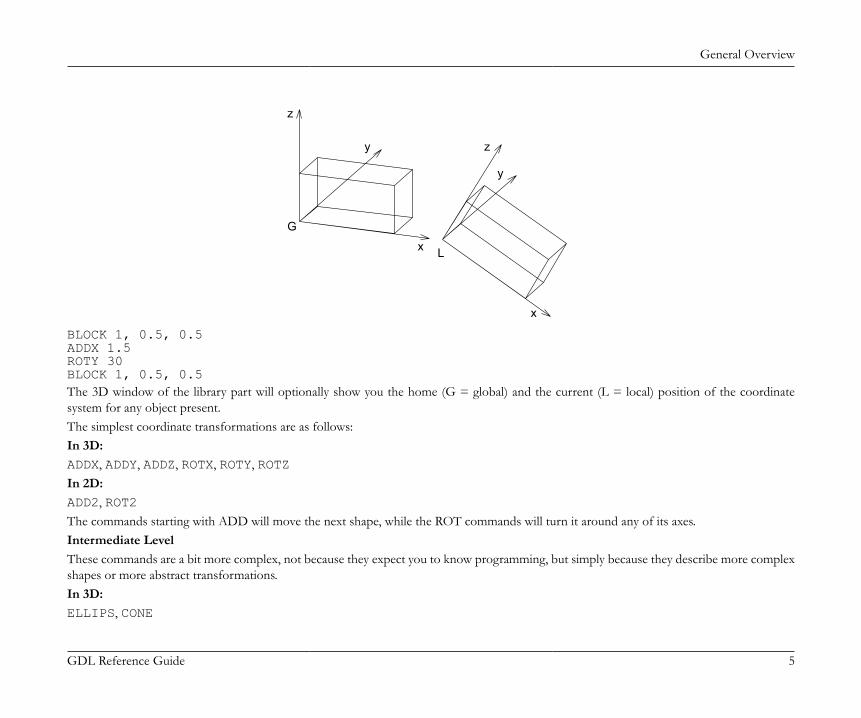
General Overview
GDL Reference Guide 5
L
G
x
y
z
x
y
z
BLOCK 1, 0.5, 0.5ADDX 1.5ROTY 30BLOCK 1, 0.5, 0.5The 3D window of the library part will optionally show you the home (G = global) and the current (L = local) position of the coordinatesystem for any object present.The simplest coordinate transformations are as follows:In 3D:ADDX, ADDY, ADDZ, ROTX, ROTY, ROTZIn 2D:ADD2, ROT2The commands starting with ADD will move the next shape, while the ROT commands will turn it around any of its axes.Intermediate LevelThese commands are a bit more complex, not because they expect you to know programming, but simply because they describe more complexshapes or more abstract transformations.In 3D:ELLIPS, CONE
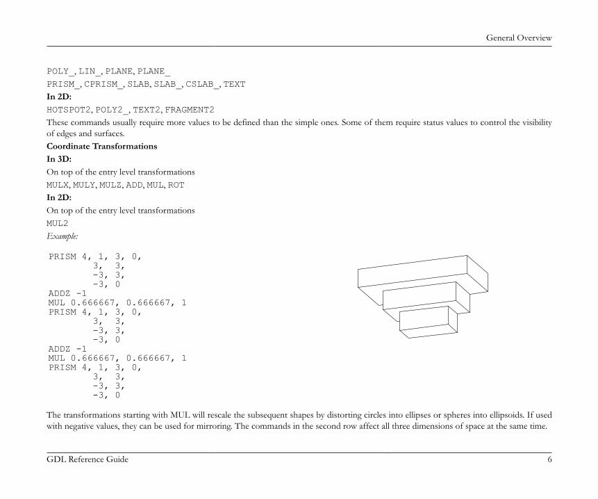
General Overview
GDL Reference Guide 6
POLY_, LIN_, PLANE, PLANE_PRISM_, CPRISM_, SLAB, SLAB_, CSLAB_, TEXTIn 2D:HOTSPOT2, POLY2_, TEXT2, FRAGMENT2These commands usually require more values to be defined than the simple ones. Some of them require status values to control the visibilityof edges and surfaces.Coordinate TransformationsIn 3D:On top of the entry level transformationsMULX, MULY, MULZ, ADD, MUL, ROTIn 2D:On top of the entry level transformationsMUL2Example:
PRISM 4, 1, 3, 0, 3, 3, -3, 3, -3, 0ADDZ -1MUL 0.666667, 0.666667, 1PRISM 4, 1, 3, 0, 3, 3, -3, 3, -3, 0ADDZ -1MUL 0.666667, 0.666667, 1PRISM 4, 1, 3, 0, 3, 3, -3, 3, -3, 0
The transformations starting with MUL will rescale the subsequent shapes by distorting circles into ellipses or spheres into ellipsoids. If usedwith negative values, they can be used for mirroring. The commands in the second row affect all three dimensions of space at the same time.
General Overview
GDL Reference Guide 7
Advanced LevelThese commands add a new level of complexity either because of their geometric shape, or because they represent GDL as a programminglanguage.In 3D:
BPRISM_ BWALL_ CWALL_ XWALL_
CROOF_ FPRISM_ SPRISM_
EXTRUDE PYRAMID REVOLVE RULED
SWEEP TUBE TUBEA COONS
MESH MASS
LIGHT PICTURE
There are shape commands in this group which let you trace a spatial polygon with a base polygon to make smooth curved surfaces. Someshapes require material references in their parameter list.By using cutting planes, polygons and shapes, you can generate complex arbitrary shapes out of simple shapes. The corresponding commandsare CUTPLANE, CUTPOLY, CUTPOLYA, CUTSHAPE and CUTEND.In 2D:PICTURE2, POLY2_A, SPLINE2, SPLINE2AFlow Control and Conditional StatementsFOR - TO - NEXTDO - WHILE, WHILE - ENDWHILEREPEAT - UNTILIF - THEN - ELSE - ENDIFGOTO, GOSUBRETURN, END / EXITThese commands should be familiar to anyone who has ever programmed a computer, but they are basic enough that you can understandthem without prior programming experience.They let you make repetitive script parts to place several shapes with little scripting, or let you make decisions based on prior calculations.
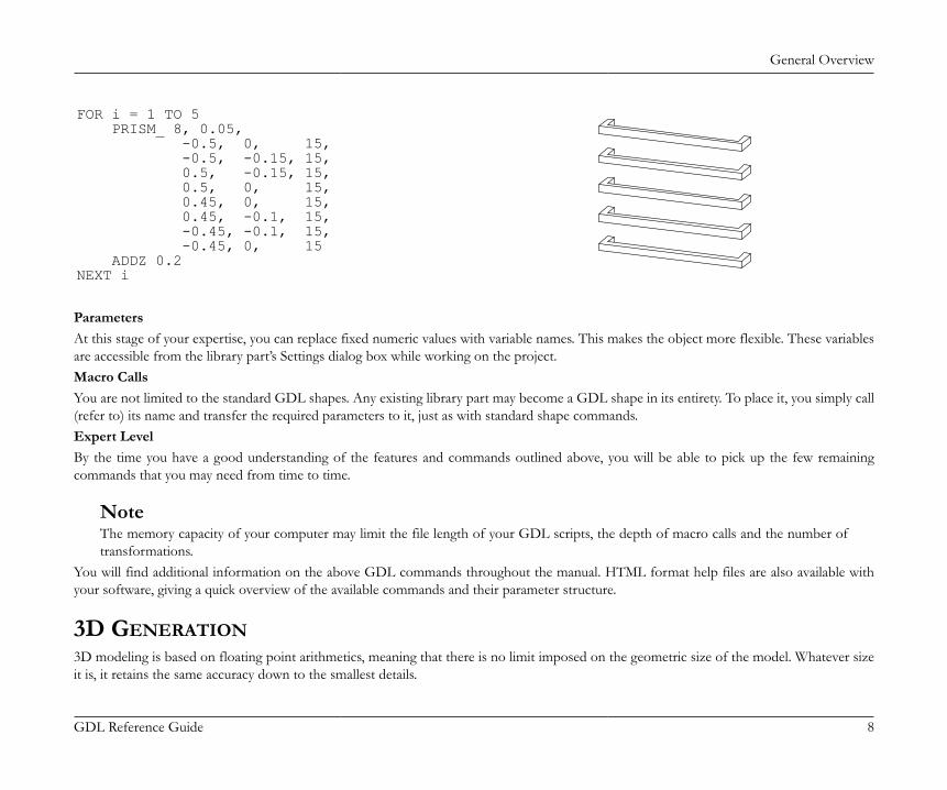
General Overview
GDL Reference Guide 8
FOR i = 1 TO 5 PRISM_ 8, 0.05, -0.5, 0, 15, -0.5, -0.15, 15, 0.5, -0.15, 15, 0.5, 0, 15, 0.45, 0, 15, 0.45, -0.1, 15, -0.45, -0.1, 15, -0.45, 0, 15 ADDZ 0.2NEXT i
ParametersAt this stage of your expertise, you can replace fixed numeric values with variable names. This makes the object more flexible. These variablesare accessible from the library part’s Settings dialog box while working on the project.Macro CallsYou are not limited to the standard GDL shapes. Any existing library part may become a GDL shape in its entirety. To place it, you simply call(refer to) its name and transfer the required parameters to it, just as with standard shape commands.Expert LevelBy the time you have a good understanding of the features and commands outlined above, you will be able to pick up the few remainingcommands that you may need from time to time.
NoteThe memory capacity of your computer may limit the file length of your GDL scripts, the depth of macro calls and the number oftransformations.
You will find additional information on the above GDL commands throughout the manual. HTML format help files are also available withyour software, giving a quick overview of the available commands and their parameter structure.
3D GENERATION3D modeling is based on floating point arithmetics, meaning that there is no limit imposed on the geometric size of the model. Whatever sizeit is, it retains the same accuracy down to the smallest details.

General Overview
GDL Reference Guide 9
The 3D model that you finally see on the screen is composed of geometric primitives. These primitives are stored in the memory of yourcomputer in binary format, and the 3D engine generates them according to the floor plan you created. The metamorphosis between thearchitectural floor plan elements and the binary 3D data is called 3D conversion.The primitives are the following:• all the vertices of your building components• all the edges linking the vertices• all the surface polygons within the edgesGroups of these primitives are kept together as bodies. The bodies make up the 3D model. All of the features of 3D visualization - smoothsurfaces, cast shadows, glossy or transparent materials - are based on this data structure.The 3D SpaceThe 3D model is created in three-dimensional space measured by the x, y and z axes of a master coordinate system whose origin is calledthe global origin.In Floor Plan view, you can see the global origin in the lower left corner of the worksheet if you open the program without reading a specificdocument. In addition, the global origin defines the zero level of all the stories referred to in a floor plan document.When you place an object into the design, the floor plan position will define its location along the x and y axes of this master coordinate system.The location along the z axis can be set in the Object Settings dialog box or directly adjusted when placed in 3D. This location will be the baseand the default position of the local coordinate system of the object. The shapes described in the script will be positioned with referenceto this local coordinate system.Coordinate TransformationsEvery GDL shape is linked to the current position of the local coordinate system. For example, blocks are linked to the origin. The length,width and height of the block are always measured in a positive direction along the three axes. Thus, the BLOCK command requires only threeparameters defining its dimensions along the axes.How can you generate a shifted and rotated block? With the parameter structure of the BLOCK there is no way to do this. It does not haveparameters for shift and rotation.The answer is to move the coordinate system to the correct position before issuing the BLOCK command. With the coordinate transformationcommands, you can pre-define its position and rotation around the axes. These transformations are not applied to the shapes already generatedand are only effective on subsequent shapes.The GDL InterpreterWhen a GDL script is executed, the GDL interpreter engine will detect the location, size, rotation angle, user defined parameters and themirrored state of the library part. It will then move the local coordinate system to the right position, ready to receive the GDL commands
General Overview
GDL Reference Guide 10
from the script of the library parts. Every time a command for a basic shape is read by the interpreter, it will generate the geometric primitivesthat make up that particular shape.When the interpreter has finished, the complete binary 3D model will be stored in the memory, and you can perform 3D projections, fly-through renderings or sun studies on it.ARCHICAD contains a pre-compiler and an interpreter for GDL. Interpretation of a GDL script uses the pre-compiled code. This featureincreases speed of the analysis. If the GDL script is modified, a new code is generated.Data structures converted from other file formats (e.g., DXF, Zoom, Alias Wavefront) are stored in a binary 3D section of the library parts.This section is referenced by the BINARY command from the GDL script.The GDL Script AnalysisUsers have no control over the order in which library parts placed on the floor plan are analyzed. The order of GDL script analysis is basedon the internal data structure; moreover, Undo and Redo operations as well as modifications may influence that order. The only exceptions tothis rule are special GDL scripts of the active library, whose names begin with "MASTER_GDL" or "MASTEREND_GDL".Scripts whose name begins with "MASTER_GDL" are executed before starting a list process and after loading the active library.Scripts whose name begins with "MASTEREND_GDL" are executed when the active library is to be changed (Load Libraries, Open a project,New project, Quit).These scripts are not executed when you edit library parts. If your library contains one or more such scripts they will all be executed in anorder that is not defined.MASTER_GDL and MASTEREND_GDL scripts can include attribute definitions, initializations of GDL user global variables, 3D commands(effective only in the 3D model), value list definitions (see the VALUES command) and GDL extension-specific commands. The attributesdefined in these scripts will be merged into the current attribute set (attributes with same names are not replaced, while attributes originatedfrom GDL and not edited in the program are always replaced).
GDL Syntax
GDL Reference Guide 11
GDL SYNTAXThis chapter presents the basic elements of GDL syntax, including statements, labels, identifiers, variables and parameters. Typographic rules are also explained in detail.
RULES OF GDL SYNTAXGDL is not case sensitive; uppercase and lowercase letters are not distinguished, except in strings placed between quotation marks. The logicalend of a GDL script is denoted by an END / EXIT statement or the physical end of the script.
STATEMENTSA GDL program consists of statements. A statement can start with a keyword (defining a GDL shape, coordinate transformations or programcontrol flow), with a macro name, or with a variable name followed by an '=' sign and an expression.
LINEThe statements are in lines separated by line-separators (end_of_line characters).A comma (,) in the last position indicates that the statement continues on the next line. A colon (:) is used for separating GDL statements ina line. After an exclamation mark (!) you can write any comment in the line. Blank lines can be inserted into a GDL script with no effect atall. Any number of spaces or tabs can be used between the operands and operators. The use of a space or tab is obligatory after statementkeywords and macro calls.
LABELAny line can start with a label which is used as a reference for a subsequent statement. A label is an integer number or a constant string betweenquotation marks, followed by a colon (:). A string label is case sensitive. Labels are checked for single occurrence. The execution of the programcan be continued from any label by using a GOTO or GOSUB statement.
CHARACTERSThe GDL text is composed of the lower and uppercase letters of the English alphabet, any number and the following characters:<space> _(underline) ~ ! : , ; . + - * / ^ = < > <= >= # ( ) [ ] { } \ @ & |(verticalbar) " ' ` ´ “ ” ’ ‘ <end_of_line>

GDL Syntax
GDL Reference Guide 12
STRINGSAny string of Unicode characters that is placed between quotation marks (", ', “, ’, `, ´), or any string of characters without quotation marks thatdoes not figure in the script as an identifier with a given value (macro call, attribute name, file name). Strings without quotation marks will beconverted to all caps, so using quotation marks is recommended. The maximum length allowed in a string is 255 characters.The '\' character has special control values. Its meaning depends on the next character.
\\ '\' char itself
\n new line
\t tabulator
\new line continue string in next line without a new line
\others not correct, results in warning
Example:"This is a string"`washbasin 1'-6"*1'-2`'Do not use different delimiters’
IDENTIFIERSIdentifiers are special ASCII character strings:• they are not longer than 255 characters;• they begin with a letter of the alphabet or a '_' or '~' character;• they consist of ASCII letters, numbers and '_' or '~' characters;• upper- and lowercase letters are considered identical.Identifiers can be GDL keywords, global or local variables or strings (names). Keywords and global variable names are determined by theprogram you’re using GDL in; all other identifiers can be used as variable names.
VARIABLESGDL programs can handle numeric and string variables (defined by their identifiers), numbers and character strings.There are two sets of variables: local and global.

GDL Syntax
GDL Reference Guide 13
All identifiers that are not keywords, global variables, attribute names, macro names or file names are considered local variables. If leftuninitialized (undefined), their value will be 0 (integer). Local variables are stacked with macro calls. When returning from a macro call, theinterpreter restores their values.Global variables have reserved names (for the list of global variables see the section called “Global Variables”). They are not stacked during macro calls,enabling the user to store special values of the modeling and to simulate return codes from macros. The user global variables can be set in anyscript but they will only be effective in subsequent scripts. If you want to make sure that the desired script is analyzed first, set these variables inthe MASTER_GDL library part. All elements will always read these values set by the Master GDL first, unless their own scripts (caller objector called macro) modify those values. There is no user global data exchange between the different interpretation instances. The other globalvariables can be used in your scripts to communicate with the program. By using the "=" command, you can assign a numeric or string valueto local and global variables.
PARAMETERSIdentifiers listed in a library part’s parameter list are called parameters. Parameter identifiers must not exceed 31 characters in length. And themaximum number of parameters must not exceed 1024. Within a script, the same rules apply to parameters as to local variables.Parameters of text-only GDL files are identified by letters A to Z.
SIMPLE TYPESVariables, parameters and expressions can be of two simple types: numeric or string.Numeric expressions are constant numbers, numeric variables or parameters, functions that return numeric values, and any combination of these inoperations. Numeric expressions can be integer or real. Integer expressions are integer constants, variables or parameters, functions that returninteger values, and any combination of these in operations which results in integers. Real expressions are real constants, variables or parameters,functions that return real values, and any combination of these (or integer expressions) in operations which results in reals. A numeric expressionbeing an integer or a real is determined during the compilation process and depends only on the constants, variables, parameters and theoperations used to combine them. Real and integer expressions can be used the same way at any place where a numeric expression is required,however, in cases where a combination of these may result in precision problems, a compiler warning appears (comparison of reals or reals andintegers using relational operators '=' or '<>', or boolean operators AND, OR, EXOR; IF or GOTO statements with real label expressions).String expressions are constant strings, string variables or parameters, functions that return strings, and any combination of these in operationswhich result in strings.
DERIVED TYPESVariables and parameters can also be arrays, and parameters can be value lists of a simple type.
GDL Syntax
GDL Reference Guide 14
Arrays are one- or two-dimensional tables of numeric and/or string values, which can be accessed directly by indexes.Value lists are sets of possible numeric or string values. They can be assigned to the parameters in the value list script of the library part or inthe MASTER_GDL script, and will appear in the parameter list as a pop-up menu.
STRUCTURED TYPESVariables and parameters can also be dictionaries. Compatibility: introduced in ARCHICAD 23.Dictionaries are a hierarchical collection of key and value pairs. Keys can contain other dictionary, array, integer, string or floating-point type values.Keys are considered identifiers (the section called “Identifiers”) - same syntax rules apply, except the '~' character is not allowed.It is not allowed to use dictionary keys (even if they are simple type) in the following places:• as FOR - TO - NEXT loop variable.• as HOTSPOT2 or HOTSPOT edited or displayed parameter.• as UI_... input parameter where the input parameter is given as an expression. (UI_INFIELD{2}, UI_INFIELD{3},UI_CUSTOM_POPUP_INFIELD{2}, UI_RADIOBUTTON, UI_PICT_RADIOBUTTON, UI_PICT_PUSHCHECKBUTTON,UI_TEXTSTYLE_INFIELD, UI_LISTITEM{2}, UI_CUSTOM_POPUP_LISTITEM{2}, UI_COLORPICKER{2},UI_SLIDER{2})
• as UI_... input parameter where the input parameter is given as a string, if the string evaluates to a dictionary type parameter.• as VALUES or VALUES{2} parameter - value lists cannot be applied.• as REQUEST returned values - only root level of a dictionary is allowed in requests that support it.• as APPLICATION_QUERY, SPLIT, INPUT, LIBRARYGLOBAL or CALLFUNCTION returned values.• as STR{2} returned extra_accuracy_string.• as RETURNED_PARAMETERS of a CALL - only returned dictionaries can be stored only at the root level of a dictionary.
CONVENTIONS USED IN THIS BOOK[aaa]Square brackets mean that the enclosed elements are optional (if they are bold, they must be entered as shown).{n}command version number...Previous element may be repeated|
GDL Syntax
GDL Reference Guide 15
Exclusive or relation between parameters of a commandvariableAny GDL variable namepromptAny character string (must not contain quote character)bold_stringUPPERCASE_STRINGspecial charactersMust be entered as shownother_lowercase_string_in_parameter_listAny GDL expression

Coordinate Transformations
GDL Reference Guide 16
COORDINATE TRANSFORMATIONSThis chapter tells you about the types of transformations available in GDL (moving, scaling and rotating the coordinate system) and the waythey are interpreted and managed.About TransformationsIn GDL, all the geometric elements are linked strictly to the local coordinate system. GDL uses a right-handed coordinate system. For example,one corner of a block is in the origin and its sides are in the x-y, x-z and y-z planes.Placing a geometric element in the desired position requires two steps. First, move the coordinate system to the desired position. Second,generate the element. Every movement, rotation or stretching of the coordinate system along or around an axis is called a transformation.Transformations are stored in a stack; interpretation starts from the last one backwards. Scripts inherit this stack; they can insert new elementsonto it but can only delete the locally defined ones. It is possible to delete one, more or all of the transformations defined in the current script.After returning from a script, the locally defined transformations are removed from the stack.
2D TRANSFORMATIONSThese are the equivalents in the 2D space of the ADD, MUL and ROTZ 3D transformations.
ADD2ADD2 x, y
Example:ADD2 a, b
X
Y
X
Y
b
a
MUL2MUL2 x, y
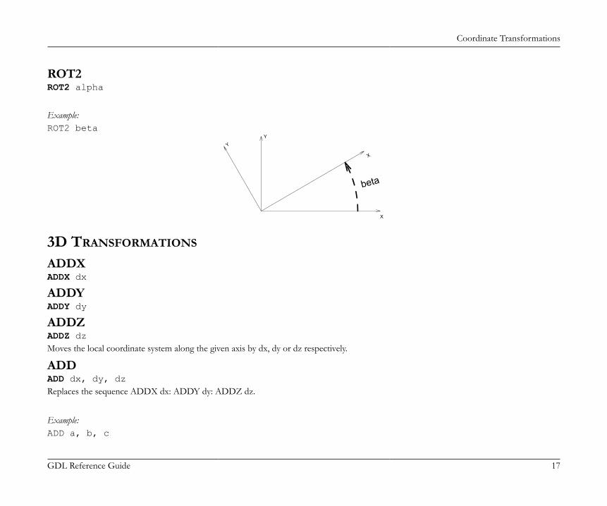
Coordinate Transformations
GDL Reference Guide 17
ROT2ROT2 alpha
Example:ROT2 beta
X
Y
X
Y
beta
3D TRANSFORMATIONS
ADDXADDX dx
ADDYADDY dy
ADDZADDZ dzMoves the local coordinate system along the given axis by dx, dy or dz respectively.
ADDADD dx, dy, dzReplaces the sequence ADDX dx: ADDY dy: ADDZ dz.
Example:ADD a, b, c
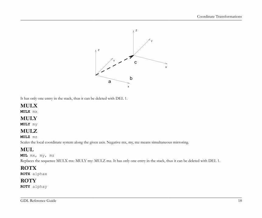
Coordinate Transformations
GDL Reference Guide 18
c
b
Z
a
Z
Y
Y
X
X
It has only one entry in the stack, thus it can be deleted with DEL 1.
MULXMULX mx
MULYMULY my
MULZMULZ mzScales the local coordinate system along the given axis. Negative mx, my, mz means simultaneous mirroring.
MULMUL mx, my, mzReplaces the sequence MULX mx: MULY my: MULZ mz. It has only one entry in the stack, thus it can be deleted with DEL 1.
ROTXROTX alphax
ROTYROTY alphay
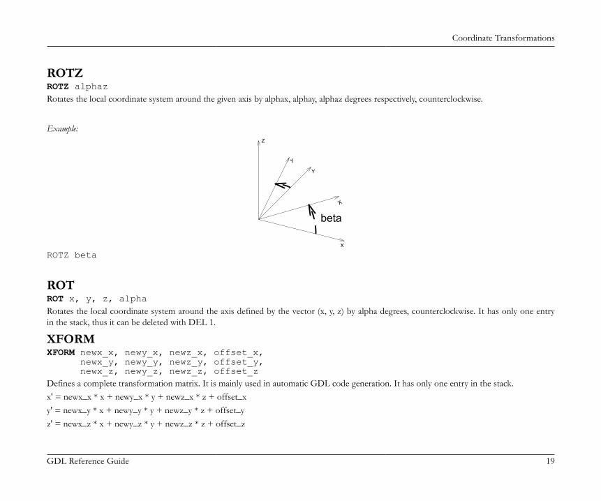
Coordinate Transformations
GDL Reference Guide 19
ROTZROTZ alphazRotates the local coordinate system around the given axis by alphax, alphay, alphaz degrees respectively, counterclockwise.
Example:
Y
X
X
Z
Y
beta
ROTZ beta
ROTROT x, y, z, alphaRotates the local coordinate system around the axis defined by the vector (x, y, z) by alpha degrees, counterclockwise. It has only one entryin the stack, thus it can be deleted with DEL 1.
XFORMXFORM newx_x, newy_x, newz_x, offset_x, newx_y, newy_y, newz_y, offset_y, newx_z, newy_z, newz_z, offset_zDefines a complete transformation matrix. It is mainly used in automatic GDL code generation. It has only one entry in the stack.x' = newx_x * x + newy_x * y + newz_x * z + offset_xy' = newx_y * x + newy_y * y + newz_y * z + offset_yz' = newx_z * x + newy_z * y + newz_z * z + offset_z

Coordinate Transformations
GDL Reference Guide 20
Example:
A=60B=30XFORM 2, COS(A), COS(B)*0.6, 0, 0, SIN(A), SIN(B)*0.6, 0, 0, 0, 1, 0BLOCK 1, 1, 1
MANAGING THE TRANSFORMATION STACK
DELDEL n [, begin_with]Deletes n entries from the transformation stack.If the begin_with parameter is not specified, deletes the previous n entries in the transformation stack. The local coordinate system movesback to a previous position.If the begin_with transformation is specified, deletes n entries forward, beginning with the one denoted by begin_with. Numbering starts with1. If the begin_with parameter is specified and n is negative, deletes backward.If fewer transformations were issued in the current script than denoted by the given n number argument, then only the issued transformationsare deleted.
DEL TOPDEL TOPDeletes all current transformations in the current script.
NTRNTR ()Returns the actual number of transformations.
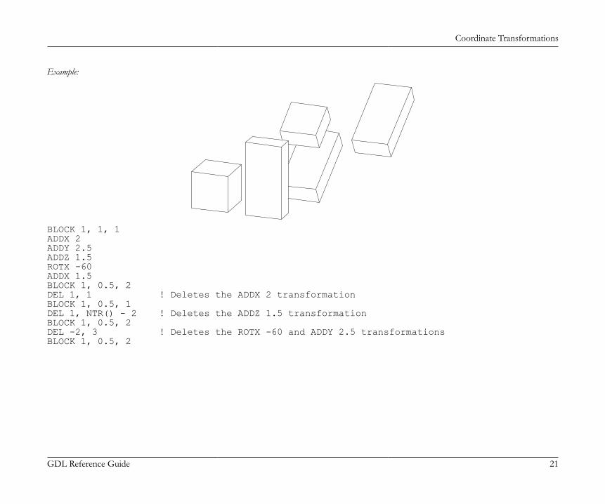
Coordinate Transformations
GDL Reference Guide 21
Example:
BLOCK 1, 1, 1ADDX 2ADDY 2.5ADDZ 1.5ROTX -60ADDX 1.5BLOCK 1, 0.5, 2DEL 1, 1 ! Deletes the ADDX 2 transformationBLOCK 1, 0.5, 1DEL 1, NTR() - 2 ! Deletes the ADDZ 1.5 transformationBLOCK 1, 0.5, 2DEL -2, 3 ! Deletes the ROTX -60 and ADDY 2.5 transformationsBLOCK 1, 0.5, 2
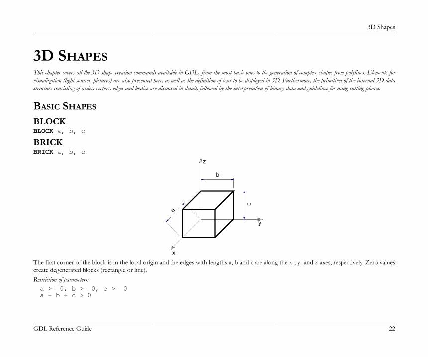
3D Shapes
GDL Reference Guide 22
3D SHAPESThis chapter covers all the 3D shape creation commands available in GDL, from the most basic ones to the generation of complex shapes from polylines. Elements forvisualization (light sources, pictures) are also presented here, as well as the definition of text to be displayed in 3D. Furthermore, the primitives of the internal 3D datastructure consisting of nodes, vectors, edges and bodies are discussed in detail, followed by the interpretation of binary data and guidelines for using cutting planes.
BASIC SHAPES
BLOCKBLOCK a, b, c
BRICKBRICK a, b, c
x
y
z
b
ca
The first corner of the block is in the local origin and the edges with lengths a, b and c are along the x-, y- and z-axes, respectively. Zero valuescreate degenerated blocks (rectangle or line).Restriction of parameters:a >= 0, b >= 0, c >= 0a + b + c > 0
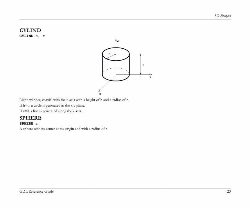
3D Shapes
GDL Reference Guide 23
CYLINDCYLIND h, r
x
y
z
r
h
Right cylinder, coaxial with the z-axis with a height of h and a radius of r.If h=0, a circle is generated in the x-y plane.If r=0, a line is generated along the z axis.
SPHERESPHERE rA sphere with its center at the origin and with a radius of r.
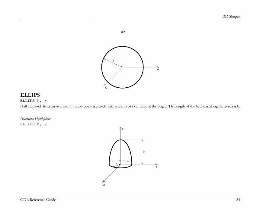
3D Shapes
GDL Reference Guide 24
x
y
z
r
ELLIPSELLIPS h, rHalf ellipsoid. Its cross-section in the x-y plane is a circle with a radius of r centered at the origin. The length of the half axis along the z-axis is h.
Example: HemisphereELLIPS h, r
x
y
z
h
r

3D Shapes
GDL Reference Guide 25
CONECONE h, r1, r2, alpha1, alpha2
y
x
z
x
z
r1
r2
h
alpha2
alpha1
Frustum of a cone where alpha1 and alpha2 are the angles of inclination of the end surfaces to the z axis, r1 and r2 are the radii of the end-circles and h is the height along the z axis.If h=0, the values of alpha1 and alpha2 are disregarded and an annulus is generated in the x-y plane.alpha1 and alpha2 are in degrees.Restriction of parameters:0 < alpha1 < 180° and 0 < alpha2 < 180°
Example: A regular coneCONE h, r, 0, 90, 90
PRISMPRISM n, h, x1, y1, ..., xn, ynRight prism with its base polygon in the x-y plane (see the parameters of the POLY command and the POLY_ command). The height alongthe z-axis is abs(h). Negative h values can also be used. In that case the second base polygon is below the x-y plane.Restriction of parameters:n >= 3

3D Shapes
GDL Reference Guide 26
x
y
z
h
n
12
PRISM_PRISM_ n, h, x1, y1, s1, ..., xn, yn, snSimilar to the PRISM command, but any of the horizontal edges and sides can be omitted.Restriction of parameters:n >= 3
si: status code that allows you to control the visibility of polygon edges and side surfaces. You can also define holes and create segmentsand arcs in the polyline using special constraints.
See Status Codes for details.

3D Shapes
GDL Reference Guide 27
Example 1: Solid and hollow faces
PRISM_ 4,1, 0,0,15, 1,1,15, 2,0,15, 1,3,15
PRISM_ 4,1, 0,0,7, 1,1,5, 2,0,15, 1,3,15
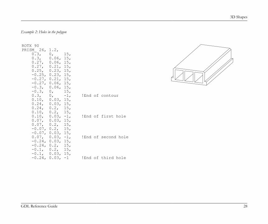
3D Shapes
GDL Reference Guide 28
Example 2: Holes in the polygon
ROTX 90PRISM_ 26, 1.2, 0.3, 0, 15, 0.3, 0.06, 15, 0.27, 0.06, 15, 0.27, 0.21, 15, 0.25, 0.23, 15, -0.25, 0.23, 15, -0.27, 0.21, 15, -0.27, 0.06, 15, -0.3, 0.06, 15, -0.3, 0, 15, 0.3, 0, -1, !End of contour 0.10, 0.03, 15, 0.24, 0.03, 15, 0.24, 0.2, 15, 0.10, 0.2, 15, 0.10, 0.03, -1, !End of first hole 0.07, 0.03, 15, 0.07, 0.2, 15, -0.07, 0.2, 15, -0.07, 0.03, 15, 0.07, 0.03, -1, !End of second hole -0.24, 0.03, 15, -0.24, 0.2, 15, -0.1, 0.2, 15, -0.1, 0.03, 15, -0.24, 0.03, -1 !End of third hole

3D Shapes
GDL Reference Guide 29
Example 3: Curved surface
j7 = 0 j7 = 1
R=1H=3PRISM_ 9, H, -R, R, 15, COS(180)*R, SIN(180)*R, 15, COS(210)*R, SIN(210)*R, 15, COS(240)*R, SIN(240)*R, 15, COS(270)*R, SIN(270)*R, 15, COS(300)*R, SIN(300)*R, 15, COS(330)*R, SIN(330)*R, 15, COS(360)*R, SIN(360)*R, 15, R, R, 15
R=1H=3PRISM_ 9, H, -R, R, 15, COS(180)*R, SIN(180)*R, 64+15, COS(210)*R, SIN(210)*R, 64+15, COS(240)*R, SIN(240)*R, 64+15, COS(270)*R, SIN(270)*R, 64+15, COS(300)*R, SIN(300)*R, 64+15, COS(330)*R, SIN(330)*R, 64+15, COS(360)*R, SIN(360)*R, 64+15, R, R, 15
CPRISM_CPRISM_ top_material, bottom_material, side_material, n, h, x1, y1, s1, ..., xn, yn, snExtension of the PRISM_ command. The first three parameters are used for the material name/index of the top, bottom and side surfaces.The other parameters are the same as above in the PRISM_ command.Restriction of parameters:

3D Shapes
GDL Reference Guide 30
n >= 3See also the section called “Materials”.si: status code that allows you to control the visibility of polygon edges and side surfaces. You can also define holes and create segments
and arcs in the polyline using special constraints.See Status Codes for details.
Example: Material referencing a predefined material by name, index and global variable
CPRISM_ "Mtl-Iron", 0, SYMB_MAT, 13, 0.2, 0, 0, 15, 2, 0, 15, 2, 2, 15, 0, 2, 15, 0, 0, -1, !end of the contour 0.2, 0.2, 15, 1.8, 0.2, 15, 1.0, 0.9, 15, 0.2, 0.2, -1, !end of first hole 0.2, 1.8, 15, 1.8, 1.8, 15, 1.0, 1.1, 15, 0.2, 1.8, -1 !end of second hole
CPRISM_{2}CPRISM_{2} top_material, bottom_material, side_material, n, h, x1, y1, alpha1, s1, mat1, ... xn, yn, alphan, sn, matn

3D Shapes
GDL Reference Guide 31
CPRISM_{2} is an extension of the CPRISM_ command with the possibility of defining different angles and materials for each side of the prism.The side angle definition is similar to the one of the CROOF_ command.alphai: the angle between the face belonging to the edge i of the prism and the plane perpendicular to the base.mati: material reference that allows you to control the material of the side surfaces.
CPRISM_{3}CPRISM_{3} top_material, bottom_material, side_material, mask, n, h, x1, y1, alpha1, s1, mat1, ... xn, yn, alphan, sn, matnCPRISM_{3} is an extension of the CPRISM_{2} command with the possibility of controlling the global behavior of the generated prism.mask: controls the global behavior of the generated prism.mask = j1 + 2*j2 + 4*j3 + 8*j4, where each j can be 0 or 1.j1: top edge in line elimination.j2: bottom edge in line elimination.j3: side edge in line elimination.j4: side edge and surface is smooth in curved sections of the profile. Compatibility: introduced in ARCHICAD 21.
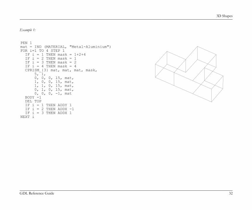
3D Shapes
GDL Reference Guide 32
Example 1:
PEN 1mat = IND (MATERIAL, "Metal-Aluminium")FOR i=1 TO 4 STEP 1 IF i = 1 THEN mask = 1+2+4 IF i = 2 THEN mask = 1 IF i = 3 THEN mask = 2 IF i = 4 THEN mask = 4 CPRISM_{3} mat, mat, mat, mask, 5, 1, 0, 0, 0, 15, mat, 1, 0, 0, 15, mat, 1, 1, 0, 15, mat, 0, 1, 0, 15, mat, 0, 0, 0, -1, mat BODY -1 DEL TOP IF i = 1 THEN ADDY 1 IF i = 2 THEN ADDX -1 IF i = 3 THEN ADDX 1NEXT i
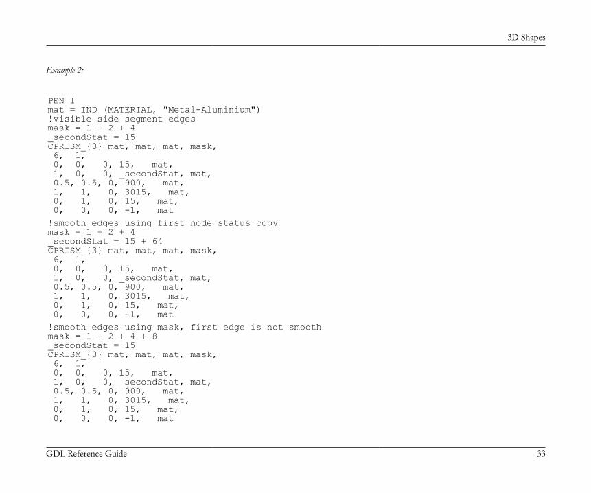
3D Shapes
GDL Reference Guide 33
Example 2:
PEN 1mat = IND (MATERIAL, "Metal-Aluminium")!visible side segment edgesmask = 1 + 2 + 4_secondStat = 15CPRISM_{3} mat, mat, mat, mask, 6, 1, 0, 0, 0, 15, mat, 1, 0, 0, _secondStat, mat, 0.5, 0.5, 0, 900, mat, 1, 1, 0, 3015, mat, 0, 1, 0, 15, mat, 0, 0, 0, -1, mat!smooth edges using first node status copymask = 1 + 2 + 4_secondStat = 15 + 64CPRISM_{3} mat, mat, mat, mask, 6, 1, 0, 0, 0, 15, mat, 1, 0, 0, _secondStat, mat, 0.5, 0.5, 0, 900, mat, 1, 1, 0, 3015, mat, 0, 1, 0, 15, mat, 0, 0, 0, -1, mat!smooth edges using mask, first edge is not smoothmask = 1 + 2 + 4 + 8_secondStat = 15CPRISM_{3} mat, mat, mat, mask, 6, 1, 0, 0, 0, 15, mat, 1, 0, 0, _secondStat, mat, 0.5, 0.5, 0, 900, mat, 1, 1, 0, 3015, mat, 0, 1, 0, 15, mat, 0, 0, 0, -1, mat

3D Shapes
GDL Reference Guide 34
CPRISM_{4}CPRISM_{4} top_material, bottom_material, side_material, mask, n, h, x1, y1, alpha1, s1, mat1, ... xn, yn, alphan, sn, matnCPRISM_{4} is an extension of the CPRISM_{3} command with the possibility of using inline material definition, that means materials definedin GDL script locally also can be used next to materials defined in global material definitions.
BPRISM_BPRISM_ top_material, bottom_material, side_material, n, h, radius, x1, y1, s1, ... xn, yn, snA smooth curved prism, based on the same data structure as the straight CPRISM_ element. The only additional parameter is radius.Derived from the corresponding CPRISM_ by bending the x-y plane onto a cylinder tangential to that plane. Edges along the x axis aretransformed to circular arcs; edges along the y axis remain horizontal; edges along the z axis will be radial in direction.See the BWALL_ command for details.si: status code that allows you to control the visibility of polygon edges and side surfaces. You can also define holes and create segments
and arcs in the polyline using special constraints.See Status Codes for details.
Example: Curved prisms with the corresponding straight ones
BPRISM_ "Glass - Blue", "Glass - Blue", "Glass - Blue", 3, 0.4, 1, ! radius = 1 0, 0, 15, 5, 0, 15, 1.3, 2, 15

3D Shapes
GDL Reference Guide 35
BPRISM_ "Concrete", "Concrete", "Concrete", 17, 0.3, 5, 0, 7.35, 15, 0, 2, 15, 1.95, 0, 15, 8, 0, 15, 6.3, 2, 15, 2, 2, 15, 4.25, 4, 15, 8, 4, 15, 8, 10, 15, 2.7, 10, 15, 0, 7.35, -1, 4, 8.5, 15, 1.85, 7.05, 15, 3.95, 5.6, 15, 6.95, 5.6, 15, 6.95, 8.5, 15, 4, 8.5, -1
FPRISM_FPRISM_ top_material, bottom_material, side_material, hill_material, n, thickness, angle, hill_height, x1, y1, s1, ... xn, yn, snSimilar to the PRISM_ command, with the additional hill_material, angle and hill_height parameters for forming a ramp on the top.hill_material: the side material of the ramp part.angle: the inclination angle of the ramp side edges.
Restriction: 0 <= angle < 90.If angle = 0, the hill side edges seen from an orthogonal view form a quarter circle with the current resolution (see the RADIUS command,the RESOL command and the TOLER command).
hill_height: the height of the ramp. Note that the thickness parameter represents the whole height of the prism.

3D Shapes
GDL Reference Guide 36
si: status code that allows you to control the visibility of polygon edges and side surfaces. You can also define holes and create segmentsand arcs in the polyline using special constraints.
Restriction of parameters:n >= 3, hill_height < thickness
See Status Codes for details.
1
n
2
hill_heightthickness
angle
Example 1: Prism with curved ramp
RESOL 10FPRISM_ "Roof Tile", "Brick-Red", "Brick-White", "Roof Tile", 4, 1.5, 0, 1.0, !angle = 0 0, 0, 15, 5, 0, 15, 5, 4, 15, 0, 4, 15
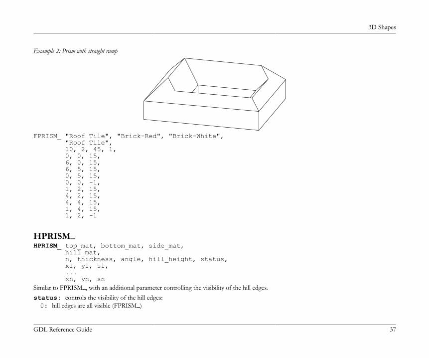
3D Shapes
GDL Reference Guide 37
Example 2: Prism with straight ramp
FPRISM_ "Roof Tile", "Brick-Red", "Brick-White", "Roof Tile", 10, 2, 45, 1, 0, 0, 15, 6, 0, 15, 6, 5, 15, 0, 5, 15, 0, 0, -1, 1, 2, 15, 4, 2, 15, 4, 4, 15, 1, 4, 15, 1, 2, -1
HPRISM_HPRISM_ top_mat, bottom_mat, side_mat, hill_mat, n, thickness, angle, hill_height, status, x1, y1, s1, ... xn, yn, snSimilar to FPRISM_, with an additional parameter controlling the visibility of the hill edges.status: controls the visibility of the hill edges:0: hill edges are all visible (FPRISM_)

3D Shapes
GDL Reference Guide 38
1: hill edges are invisible
SPRISM_SPRISM_ top_material, bottom_material, side_material, n, xb, yb, xe, ye, h, angle, x1, y1, s1, ... xn, yn, snExtension of the CPRISM_ command, with the possibility of setting the upper polygon non-parallel with the x-y plane. The upper planedefinition is similar to the plane definition of the CROOF_ command. The height of the prism is defined at the reference line. Upper andlower polygon intersection is forbidden.
n
h
1
2
(x ,y )b b(x ,y )ee
angle
xb, yb, xe, ye: reference line (vector) starting and end coordinates.angle: rotation angle of the upper polygon around the given oriented reference line in degrees (CCW).si: status code that allows you to control the visibility of polygon edges and side surfaces. You can also define holes and create segments
and arcs in the polyline using special constraints.See Status Codes for details.
Note: All calculated z coordinates of the upper polygon nodes must be positive or 0.

3D Shapes
GDL Reference Guide 39
Example:
SPRISM_ 'Grass', 'Earth', 'Earth', 6, 0, 0, 11, 6, 2, -10.0, 0, 0, 15, 10, 1, 15, 11, 6, 15, 5, 7, 15, 4.5, 5.5, 15, 1, 6, 15
SPRISM_{2}SPRISM_{2} top_material, bottom_material, side_material, n, xtb, ytb, xte, yte, topz, tangle, xbb, ybb, xbe, ybe, bottomz, bangle, x1, y1, s1, mat1, ... xn, yn, sn, matnExtension of the SPRISM_ command, with the possibility of having an upper and lower polygon non-parallel with the x-y plane. The definitionof the planes is similar to the plane definition of the CROOF_ command. The top and bottom of the prism is defined at the reference line.Upper and lower polygon intersection is forbidden.xtb, ytb, xte, yte: reference line (vector) of the top polygon starting and end coordinates.topz: the 'z' level of the reference line of the top polygon.tangle: rotation angle of the top polygon around the given oriented reference line in degrees (CCW).xbb, ybb, xbe, ybe: reference line (vector) of the bottom polygon starting and end coordinates.bottomz: the 'z' level of the reference line of the bottom polygon.bangle: rotation angle of the bottom polygon around the given oriented reference line in degrees (CCW).si: status code that allows you to control the visibility of polygon edges and side surfaces. You can also define holes and create segments
and arcs in the polyline using special constraints.See Status Codes for details.
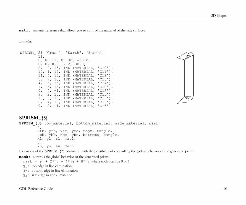
3D Shapes
GDL Reference Guide 40
mati: material reference that allows you to control the material of the side surfaces.
Example:
SPRISM_{2} 'Grass', 'Earth', 'Earth', 11, 0, 0, 11, 0, 30, -30.0, 0, 0, 0, 11, 2, 30.0, 0, 0, 15, IND (MATERIAL, 'C10'), 10, 1, 15, IND (MATERIAL, 'C11'), 11, 6, 15, IND (MATERIAL, 'C12'), 5, 7, 15, IND (MATERIAL, 'C13'), 4, 5, 15, IND (MATERIAL, 'C14'), 1, 6, 15, IND (MATERIAL, 'C10'), 0, 0, -1, IND (MATERIAL, 'C15'), 9, 2, 15, IND (MATERIAL, 'C15'), 10, 5, 15, IND (MATERIAL, 'C15'), 6, 4, 15, IND (MATERIAL, 'C15'), 9, 2, -1, IND (MATERIAL, 'C15')
SPRISM_{3}SPRISM_{3} top_material, bottom_material, side_material, mask, n, xtb, ytb, xte, yte, topz, tangle, xbb, ybb, xbe, ybe, bottomz, bangle, x1, y1, s1, mat1, ... xn, yn, sn, matnExtension of the SPRISM_{2} command with the possibility of controlling the global behavior of the generated prism.mask: controls the global behavior of the generated prism.mask = j1 + 2*j2 + 4*j3 + 8*j4, where each j can be 0 or 1.j1: top edge in line elimination.j2: bottom edge in line elimination.j3: side edge in line elimination.
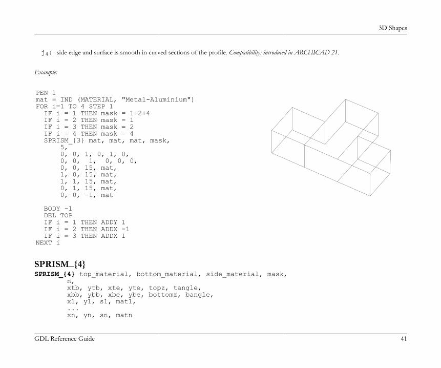
3D Shapes
GDL Reference Guide 41
j4: side edge and surface is smooth in curved sections of the profile. Compatibility: introduced in ARCHICAD 21.
Example:
PEN 1mat = IND (MATERIAL, "Metal-Aluminium")FOR i=1 TO 4 STEP 1 IF i = 1 THEN mask = 1+2+4 IF i = 2 THEN mask = 1 IF i = 3 THEN mask = 2 IF i = 4 THEN mask = 4 SPRISM_{3} mat, mat, mat, mask, 5, 0, 0, 1, 0, 1, 0, 0, 0, 1, 0, 0, 0, 0, 0, 15, mat, 1, 0, 15, mat, 1, 1, 15, mat, 0, 1, 15, mat, 0, 0, -1, mat
BODY -1 DEL TOP IF i = 1 THEN ADDY 1 IF i = 2 THEN ADDX -1 IF i = 3 THEN ADDX 1NEXT i
SPRISM_{4}SPRISM_{4} top_material, bottom_material, side_material, mask, n, xtb, ytb, xte, yte, topz, tangle, xbb, ybb, xbe, ybe, bottomz, bangle, x1, y1, s1, mat1, ... xn, yn, sn, matn

3D Shapes
GDL Reference Guide 42
SPRISM_{4} is an extension of the SPRISM_{3} command with the possibility of using inline material definition, that means materials definedin GDL script locally also can be used next to materials defined in global material definitions.
SLABSLAB n, h, x1, y1, z1, ..., xn, yn, znOblique prism. The lateral faces are always perpendicular to the x-y plane. Its bases are flat polygons rotated about an axis parallel with the x-yplane. Negative h values can also be used. In that case the second base polygon is below the given one.No check is made as to whether the points are really on a plane. Apices not lying on a plane will result in strange shadings/ renderings.Restriction of parameters:n >= 3
x
y
z
SLAB_SLAB_ n, h, x1, y1, z1, s1, ..., xn, yn, zn, snSimilar to the SLAB command, but any of the edges and faces of the side polygons can be omitted. This statement is an analogy of the PRISM_command.si: status code that allows you to control the visibility of polygon edges and side surfaces. You can also define holes and create segments
and arcs in the polyline using special constraints.See Status Codes for details.
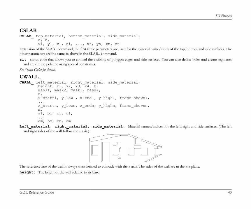
3D Shapes
GDL Reference Guide 43
CSLAB_CSLAB_ top_material, bottom_material, side_material, n, h, x1, y1, z1, s1, ..., xn, yn, zn, snExtension of the SLAB_ command; the first three parameters are used for the material name/index of the top, bottom and side surfaces. Theother parameters are the same as above in the SLAB_ command.si: status code that allows you to control the visibility of polygon edges and side surfaces. You can also define holes and create segments
and arcs in the polyline using special constraints.See Status Codes for details.
CWALL_CWALL_ left_material, right_material, side_material, height, x1, x2, x3, x4, t, mask1, mask2, mask3, mask4, n, x_start1, y_low1, x_end1, y_high1, frame_shown1, ... x_startn, y_lown, x_endn, y_highn, frame_shownn, m, a1, b1, c1, d1, ... am, bm, cm, dmLeft_material, right_material, side_material: Material names/indices for the left, right and side surfaces. (The left
and right sides of the wall follow the x axis.)
The reference line of the wall is always transformed to coincide with the x axis. The sides of the wall are in the x-z plane.height: The height of the wall relative to its base.
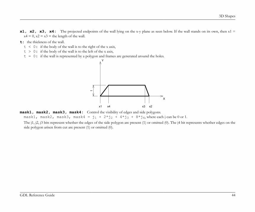
3D Shapes
GDL Reference Guide 44
x1, x2, x3, x4: The projected endpoints of the wall lying on the x-y plane as seen below. If the wall stands on its own, then x1 =x4 = 0, x2 = x3 = the length of the wall.
t: the thickness of the wall.t < 0: if the body of the wall is to the right of the x axis,t > 0: if the body of the wall is to the left of the x axis,t = 0: if the wall is represented by a polygon and frames are generated around the holes.
x4 x2x3x1
Y
X
t
mask1, mask2, mask3, mask4: Control the visibility of edges and side polygons.mask1, mask2, mask3, mask4 = j1 + 2*j2 + 4*j3 + 8*j4, where each j can be 0 or 1.The j1, j2, j3 bits represent whether the edges of the side polygon are present (1) or omitted (0). The j4 bit represents whether edges on theside polygon arisen from cut are present (1) or omitted (0).
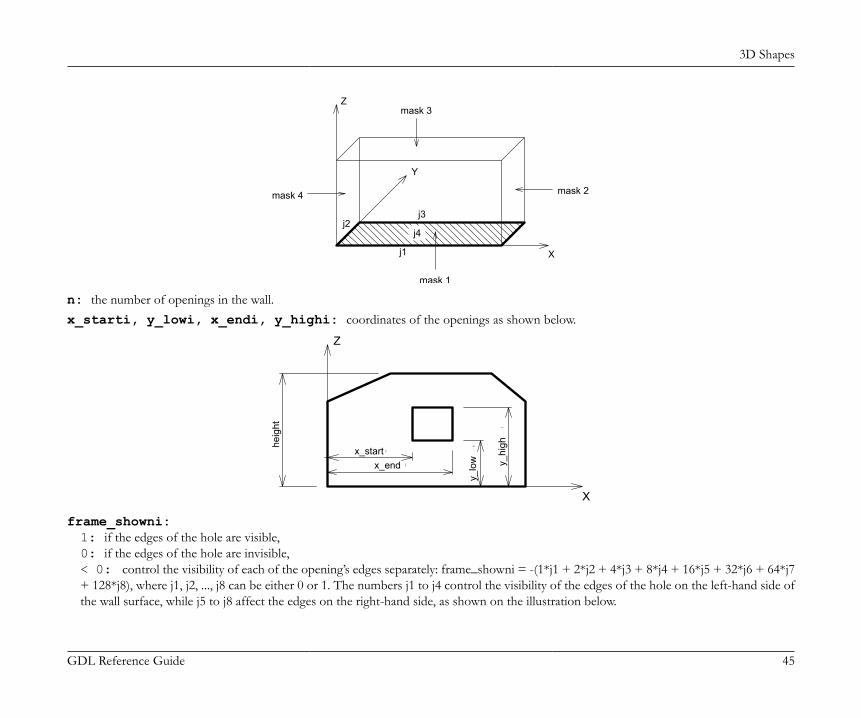
3D Shapes
GDL Reference Guide 45
j4
j3
Z
X
Y
j1
mask 1
j2
mask 4 mask 2
mask 3
n: the number of openings in the wall.x_starti, y_lowi, x_endi, y_highi: coordinates of the openings as shown below.
X
Z
i
i
i
i
heig
ht
x_startx_end
y_lo
w y_hi
gh
frame_showni:1: if the edges of the hole are visible,0: if the edges of the hole are invisible,< 0: control the visibility of each of the opening’s edges separately: frame_showni = -(1*j1 + 2*j2 + 4*j3 + 8*j4 + 16*j5 + 32*j6 + 64*j7+ 128*j8), where j1, j2, ..., j8 can be either 0 or 1. The numbers j1 to j4 control the visibility of the edges of the hole on the left-hand side ofthe wall surface, while j5 to j8 affect the edges on the right-hand side, as shown on the illustration below.
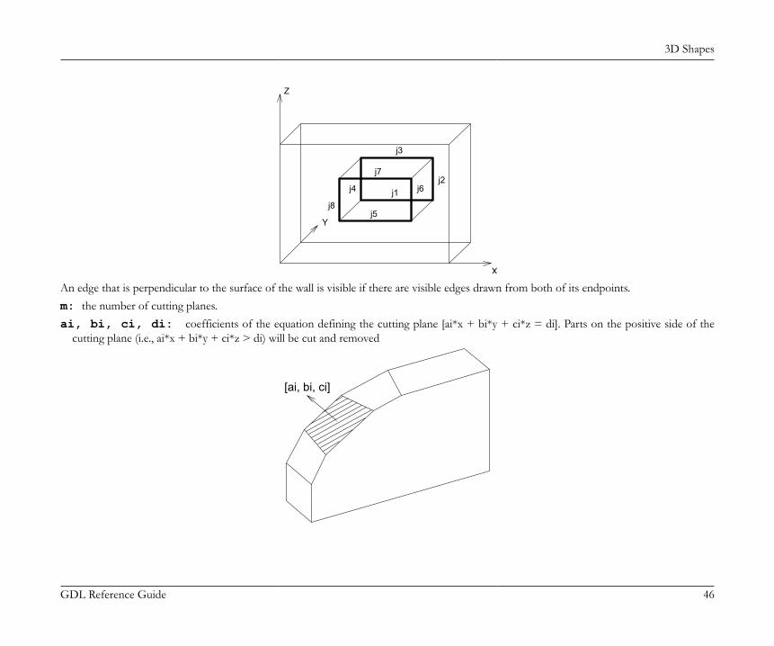
3D Shapes
GDL Reference Guide 46
j4
j3
j1j2
j5
j7
j6
j8
Y
Z
X
An edge that is perpendicular to the surface of the wall is visible if there are visible edges drawn from both of its endpoints.m: the number of cutting planes.ai, bi, ci, di: coefficients of the equation defining the cutting plane [ai*x + bi*y + ci*z = di]. Parts on the positive side of the
cutting plane (i.e., ai*x + bi*y + ci*z > di) will be cut and removed
[ai, bi, ci]
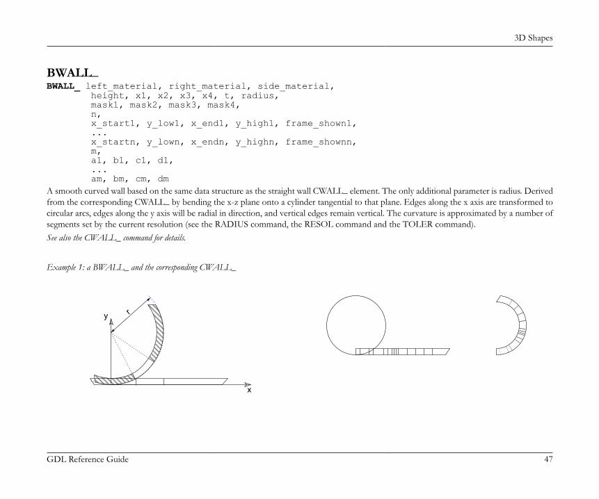
3D Shapes
GDL Reference Guide 47
BWALL_BWALL_ left_material, right_material, side_material, height, x1, x2, x3, x4, t, radius, mask1, mask2, mask3, mask4, n, x_start1, y_low1, x_end1, y_high1, frame_shown1, ... x_startn, y_lown, x_endn, y_highn, frame_shownn, m, a1, b1, c1, d1, ... am, bm, cm, dmA smooth curved wall based on the same data structure as the straight wall CWALL_ element. The only additional parameter is radius. Derivedfrom the corresponding CWALL_ by bending the x-z plane onto a cylinder tangential to that plane. Edges along the x axis are transformed tocircular arcs, edges along the y axis will be radial in direction, and vertical edges remain vertical. The curvature is approximated by a number ofsegments set by the current resolution (see the RADIUS command, the RESOL command and the TOLER command).See also the CWALL_ command for details.
Example 1: a BWALL_ and the corresponding CWALL_
y
x
r

3D Shapes
GDL Reference Guide 48
Example 2:
ROTZ -60BWALL_ 1, 1, 1, 4, 0, 6, 6, 0, 0.3, 2, 15, 15, 15, 15, 5, 1, 1, 3.8, 2.5, -255, 1.8, 0, 3, 2.5, -255, 4.1, 1, 4.5, 1.4, -255, 4.1, 1.55, 4.5, 1.95,-255, 4.1, 2.1, 4.5, 2.5, -255, 1, 0, -0.25, 1, 3
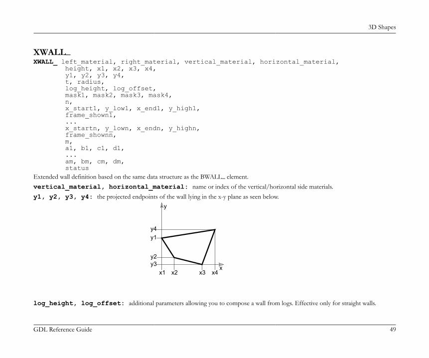
3D Shapes
GDL Reference Guide 49
XWALL_XWALL_ left_material, right_material, vertical_material, horizontal_material, height, x1, x2, x3, x4, y1, y2, y3, y4, t, radius, log_height, log_offset, mask1, mask2, mask3, mask4, n, x_start1, y_low1, x_end1, y_high1, frame_shown1, ... x_startn, y_lown, x_endn, y_highn, frame_shownn, m, a1, b1, c1, d1, ... am, bm, cm, dm, statusExtended wall definition based on the same data structure as the BWALL_ element.vertical_material, horizontal_material: name or index of the vertical/horizontal side materials.y1, y2, y3, y4: the projected endpoints of the wall lying in the x-y plane as seen below.
x
y
x1 x2 x3 x4y3y2
y1y4
log_height, log_offset: additional parameters allowing you to compose a wall from logs. Effective only for straight walls.
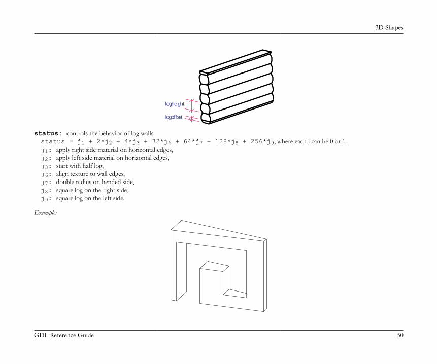
3D Shapes
GDL Reference Guide 50
logoffset
logheight
status: controls the behavior of log wallsstatus = j1 + 2*j2 + 4*j3 + 32*j6 + 64*j7 + 128*j8 + 256*j9, where each j can be 0 or 1.j1: apply right side material on horizontal edges,j2: apply left side material on horizontal edges,j3: start with half log,j6: align texture to wall edges,j7: double radius on bended side,j8: square log on the right side,j9: square log on the left side.
Example:
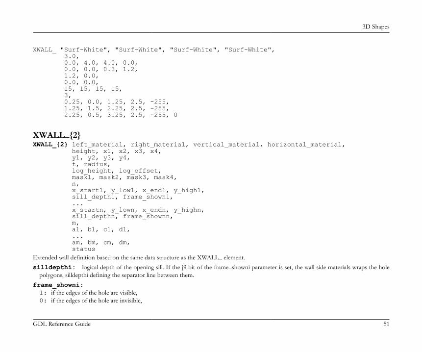
3D Shapes
GDL Reference Guide 51
XWALL_ "Surf-White", "Surf-White", "Surf-White", "Surf-White", 3.0, 0.0, 4.0, 4.0, 0.0, 0.0, 0.0, 0.3, 1.2, 1.2, 0.0, 0.0, 0.0, 15, 15, 15, 15, 3, 0.25, 0.0, 1.25, 2.5, -255, 1.25, 1.5, 2.25, 2.5, -255, 2.25, 0.5, 3.25, 2.5, -255, 0
XWALL_{2}XWALL_{2} left_material, right_material, vertical_material, horizontal_material, height, x1, x2, x3, x4, y1, y2, y3, y4, t, radius, log_height, log_offset, mask1, mask2, mask3, mask4, n, x_start1, y_low1, x_end1, y_high1, sill_depth1, frame_shown1, ... x_startn, y_lown, x_endn, y_highn, sill_depthn, frame_shownn, m, a1, b1, c1, d1, ... am, bm, cm, dm, statusExtended wall definition based on the same data structure as the XWALL_ element.silldepthi: logical depth of the opening sill. If the j9 bit of the frame_showni parameter is set, the wall side materials wraps the hole
polygons, silldepthi defining the separator line between them.frame_showni:1: if the edges of the hole are visible,0: if the edges of the hole are invisible,

3D Shapes
GDL Reference Guide 52
< 0: control the visibility of each of the opening’s edges separately: frame_showni = -(1*j1 + 2*j2 + 4*j3 + 8*j4 + 16*j5 + 32*j6 + 64*j7+ 128*j8 + 256*j9 + 512*j10), where j1, j2, ..., j10 can be either 0 or 1. There are two additional values to control the material wrapping.The meaning of the j1, j2, ..., j8 values are the same as at the CWALL_ and XWALL_ commands. The j9 value controls the material of thehole polygons. If j9 is 1, the hole inherits the side materials of the wall. The j10 value controls the form of the separator line between thehole materials on the upper and lower polygons of the hole in case of a bent wall. If the j10 value is 1, the separator line will be straight,otherwise curved.
XWALL_{3}XWALL_{3} left_material, right_material, vertical_material, horizontal_material, height, x1, x2, x3, x4, y1, y2, y3, y4, t, radius, log_height, log_offset, mask1, mask2, mask3, mask4, n, x_start1, y_low1, x_end1, y_high1, sill_depth1, frame_shown1, ... x_startn, y_lown, x_endn, y_highn, sill_depthn, frame_shownn, m, a1, b1, c1, d1, ... am, bm, cm, dm, statusXWALL_{3} is an extension of XWALL_{2} command with the possibility of hiding all edges of the log wall.status: controls the behavior of log wallsstatus = j1 + 2*j2 + 4*j3 + 32*j6 + 64*j7 + 128*j8 + 256*j9 + 512*j10, where each j can be 0 or 1.j1: apply right side material on horizontal edges,j2: apply left side material on horizontal edges,j3: start with half log,j6: align texture to wall edges,j7: double radius on bended side,j8: square log on the right side,j9: square log on the left side,
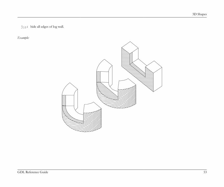
3D Shapes
GDL Reference Guide 53
j10: hide all edges of log wall.
Example:

3D Shapes
GDL Reference Guide 54
ROTZ 90xWALL_{2} "C13", "C11", "C12", "C12", 2, 0, 4, 4, 0, 0, 0, 1, 1, 1, 0, 0, 0, 15, 15, 15, 15, 1, 1, 0.9, 3, 2.1, 0.3, -(255 + 256), 0, 0DEL 1ADDX 2xWALL_{2} "C13", "C11", "C12", "C12", 2, 0, 2 * PI, 2 * PI, 0, 0, 0, 1, 1, 1, 2, 0, 0, 15, 15, 15, 15, 1, 1.6, 0.9, 4.6, 2.1, 0.3, -(255 + 256), 0, 0ADDX 4xWALL_{2} "C13", "C11", "C12", "C12", 2, 0, 2 * PI, 2 * PI, 0, 0, 0, 1, 1, 1, 2, 0, 0, 15, 15, 15, 15, 1, 1.6, 0.9, 4.6, 2.1, 0.3, -(255 + 256 + 512), 0, 0

3D Shapes
GDL Reference Guide 55
BEAMBEAM left_material, right_material, vertical_material, top_material, bottom_material, height, x1, x2, x3, x4, y1, y2, y3, y4, t, mask1, mask2, mask3, mask4Beam definition. Parameters are similar to those of the XWALL_ element.top_material, bottom_material: top and bottom materials.
Example:
BEAM 1, 1, 1, 1, 1, 0.3, 0.0, 7.0, 7.0, 0.0, 0.0, 0.0, 0.1, 0.1, 0.5, 15, 15, 15, 15
CROOF_CROOF_ top_material, bottom_material, side_material, n, xb, yb, xe, ye, height, angle, thickness, x1, y1, alpha1, s1, ... xn, yn, alphan, snA sloped roof pitch with custom angle ridges.top_material, bottom_material, side_material: name/index of the top, bottom and side material.n: the number of nodes in the roof polygon.xb, yb, xe, ye: reference line (vector).
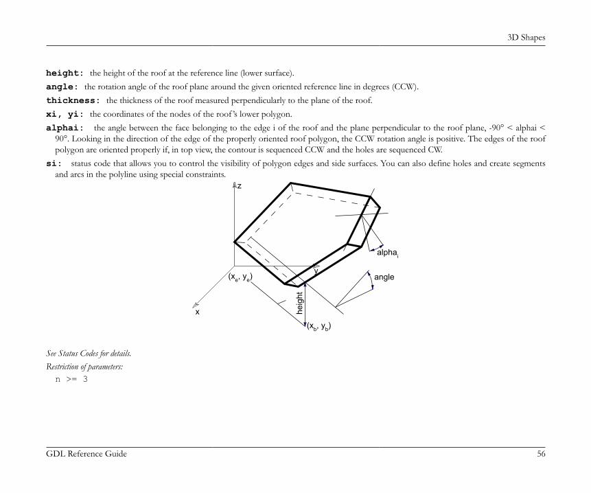
3D Shapes
GDL Reference Guide 56
height: the height of the roof at the reference line (lower surface).angle: the rotation angle of the roof plane around the given oriented reference line in degrees (CCW).thickness: the thickness of the roof measured perpendicularly to the plane of the roof.xi, yi: the coordinates of the nodes of the roof ’s lower polygon.alphai: the angle between the face belonging to the edge i of the roof and the plane perpendicular to the roof plane, -90° < alphai <
90°. Looking in the direction of the edge of the properly oriented roof polygon, the CCW rotation angle is positive. The edges of the roofpolygon are oriented properly if, in top view, the contour is sequenced CCW and the holes are sequenced CW.
si: status code that allows you to control the visibility of polygon edges and side surfaces. You can also define holes and create segmentsand arcs in the polyline using special constraints.
x
y
z
heig
ht
alphai
angle(xe, ye)
(xb, yb)
See Status Codes for details.Restriction of parameters:n >= 3

3D Shapes
GDL Reference Guide 57
Example 1:
CROOF_ 1, 1, 1, ! materials 9, 0, 0, 1, 0, ! reference line (xb,yb)(xe,ye) 0.0, ! height -30, ! angle 2.5, ! thickness 0, 0, -60, 15, 10, 0, 0, 15, 10, 20, -30, 15, 0, 20, 0, 15, 0, 0, 0, -1, 2, 5, 0, 15, 8, 5, 0, 15, 5, 15, 0, 15, 2, 5, 0, -1
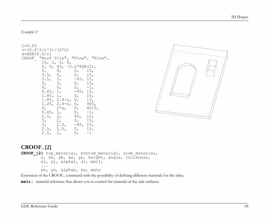
3D Shapes
GDL Reference Guide 58
Example 2:
L=0.25r=(0.6^2+L^2)/(2*L)a=ASN(0.6/r)CROOF_ "Roof Tile", "Pine", "Pine", 16, 2, 0, 0, 0, 0, 45, -0.2*SQR(2), 0, 0, 0, 15, 3.5, 0, 0, 15, 3.5, 3, -45, 15, 0, 3, 0, 15, 0, 0, 0, -1, 0.65, 1, -45, 15, 1.85, 1, 0, 15, 1.85, 2.4-L, 0, 13, 1.25, 2.4-r, 0, 900, 0, 2*a, 0, 4015, 0.65, 1, 0, -1, 2.5, 2, 45, 15, 3, 2, 0, 15, 3, 2.5, -45, 15, 2.5, 2.5, 0, 15, 2.5, 2, 0, -1
CROOF_{2}CROOF_{2} top_material, bottom_material, side_material, n, xb, yb, xe, ye, height, angle, thickness, x1, y1, alpha1, s1, mat1, ... xn, yn, alphan, sn, matnExtension of the CROOF_ command with the possibility of defining different materials for the sides.mati: material reference that allows you to control the material of the side surfaces.
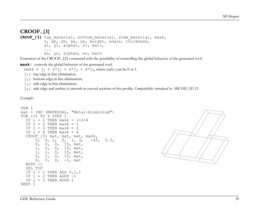
3D Shapes
GDL Reference Guide 59
CROOF_{3}CROOF_{3} top_material, bottom_material, side_material, mask, n, xb, yb, xe, ye, height, angle, thickness, x1, y1, alpha1, s1, mat1, ... xn, yn, alphan, sn, matnExtension of the CROOF_{2} command with the possibility of controlling the global behavior of the generated roof.mask: controls the global behavior of the generated roof.mask = j1 + 2*j2 + 4*j3 + 8*j4, where each j can be 0 or 1.j1: top edge in line elimination.j2: bottom edge in line elimination.j3: side edge in line elimination.j4: side edge and surface is smooth in curved sections of the profile. Compatibility: introduced in ARCHICAD 21.
Example:
PEN 1mat = IND (MATERIAL, "Metal-Aluminium")FOR i=1 TO 4 STEP 1 IF i = 1 THEN mask = 1+2+4 IF i = 2 THEN mask = 1 IF i = 3 THEN mask = 2 IF i = 4 THEN mask = 4 CROOF_{3} mat, mat, mat, mask, 5, 0, 1, 2, 1, 3, -45, 0.3, 0, 0, 0, 15, mat, 1, 0, 0, 15, mat, 1, 1, 0, 15, mat, 0, 1, 0, 15, mat, 0, 0, 0, -1, mat BODY -1 DEL TOP IF i = 1 THEN ADD 0,1,1 IF i = 2 THEN ADDX -1 IF i = 3 THEN ADDX 1NEXT i
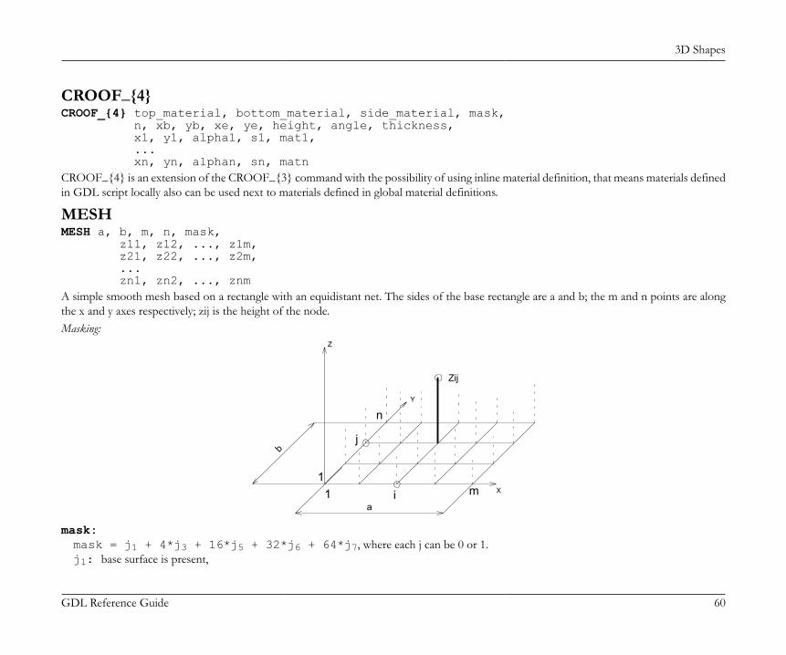
3D Shapes
GDL Reference Guide 60
CROOF_{4}CROOF_{4} top_material, bottom_material, side_material, mask, n, xb, yb, xe, ye, height, angle, thickness, x1, y1, alpha1, s1, mat1, ... xn, yn, alphan, sn, matnCROOF_{4} is an extension of the CROOF_{3} command with the possibility of using inline material definition, that means materials definedin GDL script locally also can be used next to materials defined in global material definitions.
MESHMESH a, b, m, n, mask, z11, z12, ..., z1m, z21, z22, ..., z2m, ... zn1, zn2, ..., znmA simple smooth mesh based on a rectangle with an equidistant net. The sides of the base rectangle are a and b; the m and n points are alongthe x and y axes respectively; zij is the height of the node.Masking:
i
n
m1
Y
Zij
1
Z
X
jb
a
mask:mask = j1 + 4*j3 + 16*j5 + 32*j6 + 64*j7, where each j can be 0 or 1.j1: base surface is present,
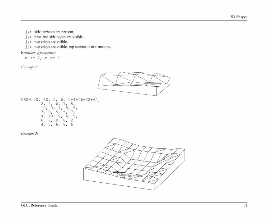
3D Shapes
GDL Reference Guide 61
j3: side surfaces are present,j5: base and side edges are visible,j6: top edges are visible,j7: top edges are visible, top surface is not smooth.
Restriction of parameters:m >= 2, n >= 2
Example 1:
MESH 50, 30, 5, 6, 1+4+16+32+64, 2, 4, 6, 7, 8, 10, 3, 4, 5, 6, 7, 9, 5, 5, 7, 8, 10, 9, 4, 5, 6, 7, 9, 8, 2, 4, 5, 6, 8, 6
Example 2:
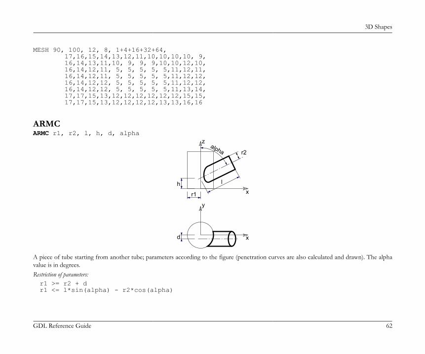
3D Shapes
GDL Reference Guide 62
MESH 90, 100, 12, 8, 1+4+16+32+64, 17,16,15,14,13,12,11,10,10,10,10, 9, 16,14,13,11,10, 9, 9, 9,10,10,12,10, 16,14,12,11, 5, 5, 5, 5, 5,11,12,11, 16,14,12,11, 5, 5, 5, 5, 5,11,12,12, 16,14,12,12, 5, 5, 5, 5, 5,11,12,12, 16,14,12,12, 5, 5, 5, 5, 5,11,13,14, 17,17,15,13,12,12,12,12,12,12,15,15, 17,17,15,13,12,12,12,12,13,13,16,16
ARMCARMC r1, r2, l, h, d, alpha
z
x
y
x
h
d
r2
r1
l
alpha
A piece of tube starting from another tube; parameters according to the figure (penetration curves are also calculated and drawn). The alphavalue is in degrees.Restriction of parameters:r1 >= r2 + dr1 <= l*sin(alpha) - r2*cos(alpha)
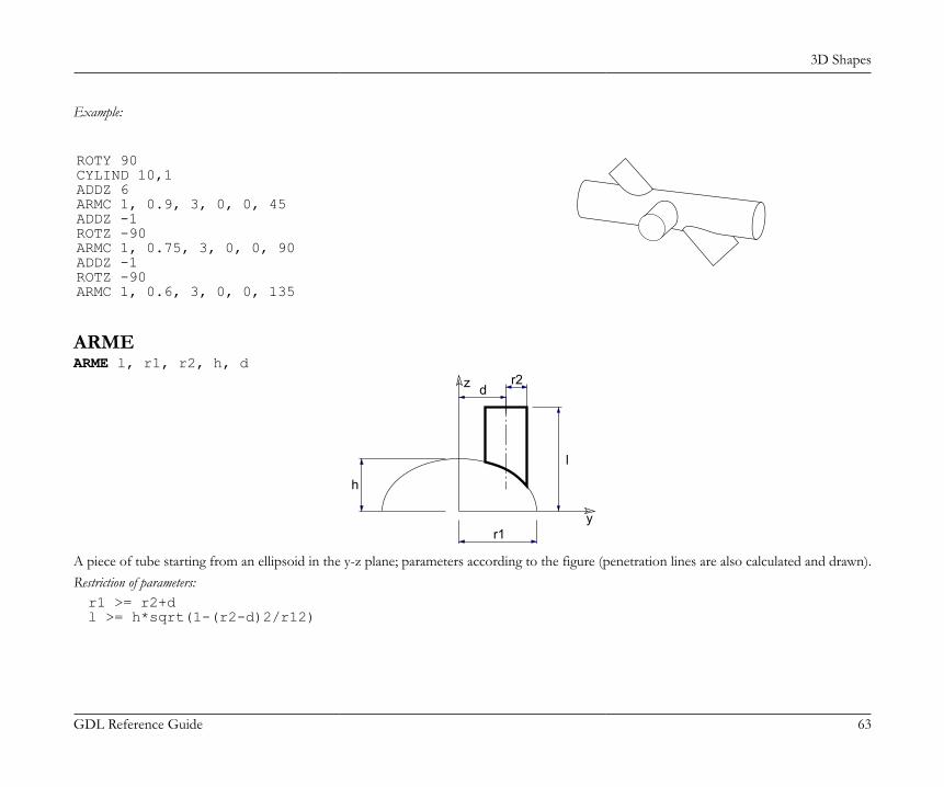
3D Shapes
GDL Reference Guide 63
Example:
ROTY 90CYLIND 10,1ADDZ 6ARMC 1, 0.9, 3, 0, 0, 45ADDZ -1ROTZ -90ARMC 1, 0.75, 3, 0, 0, 90ADDZ -1ROTZ -90ARMC 1, 0.6, 3, 0, 0, 135
ARMEARME l, r1, r2, h, d
y
z
h
dr2
r1
l
A piece of tube starting from an ellipsoid in the y-z plane; parameters according to the figure (penetration lines are also calculated and drawn).Restriction of parameters:r1 >= r2+dl >= h*sqrt(1-(r2-d)2/r12)

3D Shapes
GDL Reference Guide 64
Example:
ELLIPS 3,4FOR i=1 TO 6 ARME 6,4,0.5,3,3.7-0.2*i ROTZ 30NEXT i
ELBOWELBOW r1, alpha, r2A segmented elbow in the x-z plane. The radius of the arc is r1, the angle is alpha and the radius of the tube segment is r2. The alpha valueis in degrees.Restriction of parameters:r1 > r2
x
z
alpha r1
r2

3D Shapes
GDL Reference Guide 65
Example:
ROTY 90ELBOW 2.5, 180, 1ADDZ -4CYLIND 4, 1ROTZ -90MULZ -1ELBOW 5, 180, 1DEL 1ADDX 10CYLIND 4, 1ADDZ 4ROTZ 90ELBOW 2.5, 180, 1
PLANAR SHAPES IN 3DThe drawing elements presented in this section can be used in 3D scripts, allowing you to define points, lines, arcs, circles and planar polygonsin the three-dimensional space.
HOTSPOTHOTSPOT x, y, z [, unID [, paramReference [, flags [, displayParam [, customDescription]]]]]A 3D hotspot in the point (x, y, z).unID: the unique identifier of the hotspot in the 3D script. It is useful if you have a variable number of hotspots.paramReference: parameter that can be edited by this hotspot using the graphical hotspot based parameter editing method.displayParam: parameter to display in the information palette when editing the paramRefrence parameter. Members of arrays can be
passed as well.customDescription: custom description of the displayed parameter in the information palette. When using this option, displayParam
must be set as well (use paramReference for default).See Graphical Editing Using Hotspots for using HOTSPOT.
HOTLINEHOTLINE x1, y1, z1, x2, y2, z2, unID
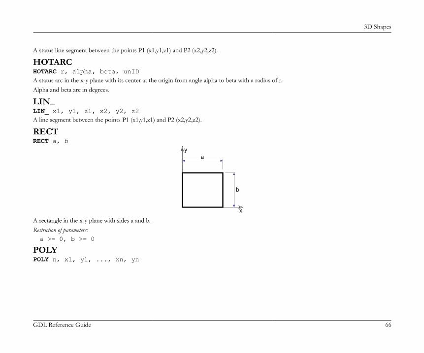
3D Shapes
GDL Reference Guide 66
A status line segment between the points P1 (x1,y1,z1) and P2 (x2,y2,z2).
HOTARCHOTARC r, alpha, beta, unIDA status arc in the x-y plane with its center at the origin from angle alpha to beta with a radius of r.Alpha and beta are in degrees.
LIN_LIN_ x1, y1, z1, x2, y2, z2A line segment between the points P1 (x1,y1,z1) and P2 (x2,y2,z2).
RECTRECT a, b
x
ya
b
A rectangle in the x-y plane with sides a and b.Restriction of parameters:a >= 0, b >= 0
POLYPOLY n, x1, y1, ..., xn, yn

3D Shapes
GDL Reference Guide 67
x
y
1 2 3
n
A polygon with n edges in the x-y plane. The coordinates of nodei are (xi, yi, 0).Restriction of parameters:n >= 3
POLY_POLY_ n, x1, y1, s1, ..., xn, yn, snSimilar to the normal POLY statement, but any of the edges can be omitted.si: status code that allows you to control the visibility of polygon edges and side surfaces. You can also define holes and create segments
and arcs in the polyline using special constraints.si = 0: the edge starting from the (xi,yi) apex will be omitted,si = 1: the edge will be shown,si = -1: is used to define holes directly.
Additional status codes allow you to create segments and arcs in the planar polyline using special constraints.See the section called “Additional Status Codes” for details.
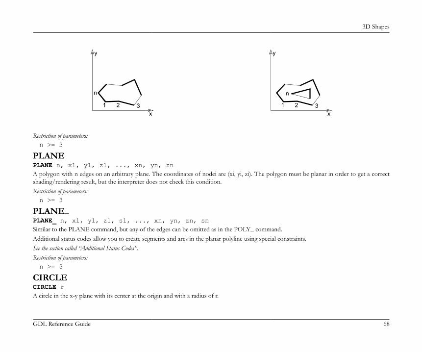
3D Shapes
GDL Reference Guide 68
x
y
1 2 3
n
x
y
1 2 3
n
Restriction of parameters:n >= 3
PLANEPLANE n, x1, y1, z1, ..., xn, yn, znA polygon with n edges on an arbitrary plane. The coordinates of nodei are (xi, yi, zi). The polygon must be planar in order to get a correctshading/rendering result, but the interpreter does not check this condition.Restriction of parameters:n >= 3
PLANE_PLANE_ n, x1, y1, z1, s1, ..., xn, yn, zn, snSimilar to the PLANE command, but any of the edges can be omitted as in the POLY_ command.Additional status codes allow you to create segments and arcs in the planar polyline using special constraints.See the section called “Additional Status Codes”.Restriction of parameters:n >= 3
CIRCLECIRCLE rA circle in the x-y plane with its center at the origin and with a radius of r.
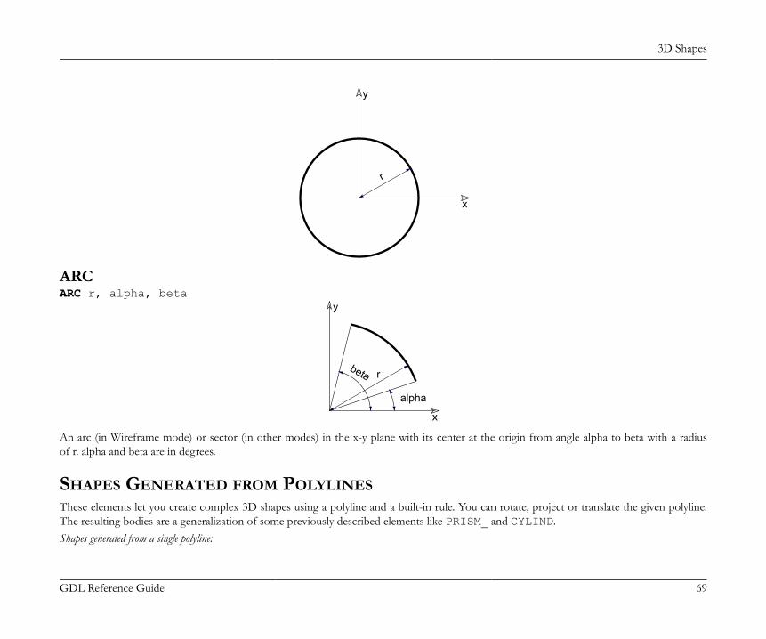
3D Shapes
GDL Reference Guide 69
x
y
r
ARCARC r, alpha, beta
x
y
r
alpha
beta
An arc (in Wireframe mode) or sector (in other modes) in the x-y plane with its center at the origin from angle alpha to beta with a radiusof r. alpha and beta are in degrees.
SHAPES GENERATED FROM POLYLINESThese elements let you create complex 3D shapes using a polyline and a built-in rule. You can rotate, project or translate the given polyline.The resulting bodies are a generalization of some previously described elements like PRISM_ and CYLIND.Shapes generated from a single polyline:

3D Shapes
GDL Reference Guide 70
• EXTRUDE• PYRAMID• REVOLVEShapes generated from two polylines:• RULED• SWEEP• TUBE• TUBEAThe first polyline is always in the x-y plane. Points are determined by two coordinates; the third value is the status (see below). The secondpolyline (for RULED, SWEEP, TUBE and TUBEA) is a space curve. Apices are determined by three coordinate values.Shape generated from four polylines:• COONSShape generated from any number of polylines:• MASSGeneral restrictions for polylines• Adjacent vertices must not be coincident (except RULED).• The polyline must not intersect itself (this is not checked by the program, but hidden line removal and rendering will be incorrect).• The polylines may be either open or closed. In the latter case, the first node must be repeated after the last one of the contour.MaskingMask values are used to show or hide characteristic surfaces and/or edges of the 3D shape. The mask values are specific to each element andyou can find a more detailed description in their corresponding sections/chapters.mask:mask = j1 + 2*j2 + 4*j3 + 8*j4 + 16*j5 + 32*j6 + 64*j7, where each j can be 0 or 1.j1, j2, j3, j4 represent whether the surfaces are present (1) or omitted (0).j5, j6, j7 represent whether the edges are visible (1) or invisible (0).j1: base surface.j2: top surface.j3: side surface.j4: other side surface.j5: base edges.j6: top edges.

3D Shapes
GDL Reference Guide 71
j7: cross-section/surface edges are visible, surface is not smooth.To enable all faces and edges, set mask value to 127.
StatusStatus values are used to state whether a given point of the polyline will leave a sharp trace of its rotation path behind.0: latitudinal arcs/lateral edges starting from the node are all visible.1: latitudinal arcs/lateral edges starting from the node are used only for showing the contour.-1: for EXTRUDE only: it marks the end of the enclosing polygon or a hole, and means that the next node will be the first node of another hole.Additional status codes allow you to create segments and arcs in the polyline using special constraints.See the section called “Additional Status Codes” for details.To create a smooth 3D shape, set all status values to 1. Use status = 0 to create a ridge.Other values are reserved for future enhancements.
EXTRUDEEXTRUDE n, dx, dy, dz, mask, x1, y1, s1, ... xn, yn, sn
x
y
z
j1
j2
j3
j5
j6
1
2
n
General prism using a polyline base in the x-y plane.

3D Shapes
GDL Reference Guide 72
The displacement vector between bases is (dx, dy, dz). This is a generalization of the PRISM command and the SLAB command. The basepolyline is not necessarily closed, as the lateral edges are not always perpendicular to the x-y plane. The base polyline may include holes, justlike PRISM_. It is possible to control the visibility of the contour edges.n: the number of polyline nodes.mask: controls the existence of the bottom, top and (in case of an open polyline) side polygon.mask = j1 + 2*j2 + 4*j3 + 16*j5 + 32*j6 + 64*j7 + 128*j8, where each j can be 0 or 1.j1: base surface is present,j2: top surface is present,j3: side (closing) surface is present,j5: base edges are visible,j6: top edges are visible.j7: cross-section edges are visible, surface is articulated,j8: cross-section edges are sharp, the surface smoothing will stop here in OpenGL and rendering.
si: status of the lateral edges or marks the end of the polygon or of a hole. You can also define arcs and segments in the polyline usingadditional status code values:0: lateral edge starting from the node is visible,1: lateral edges starting from the node are used for showing the contour,-1: marks the end of the enclosing polygon or a hole, and means that the next node will be the first vertex of another hole.
Additional status codes allow you to create segments and arcs in the planar polyline using special constraints.See the section called “Additional Status Codes” for details.Restriction of parameters:n > 2

3D Shapes
GDL Reference Guide 73
Example 1:
EXTRUDE 14, 1, 1, 4, 1+2+4+16+32, 0, 0, 0, 1, -3, 0, 2, -2, 1, 3, -4, 0, 4, -2, 1, 5, -3, 0, 6, 0, 0, 3, 4, 0, 0, 0, -1, 2, 0, 0, 3, 2, 0, 4, 0, 0, 3, -2, 0, 2, 0, -1
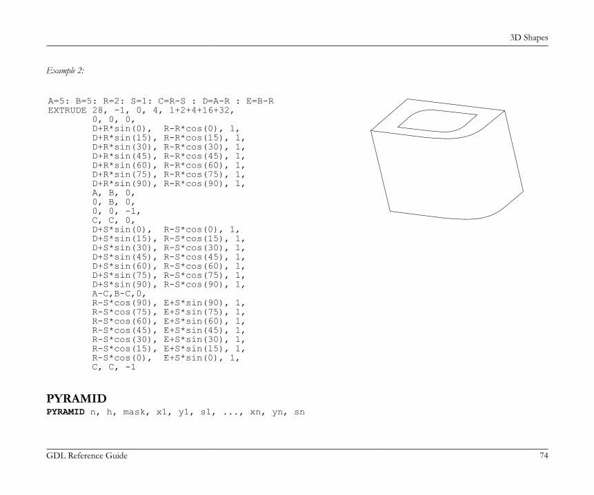
3D Shapes
GDL Reference Guide 74
Example 2:
A=5: B=5: R=2: S=1: C=R-S : D=A-R : E=B-REXTRUDE 28, -1, 0, 4, 1+2+4+16+32, 0, 0, 0, D+R*sin(0), R-R*cos(0), 1, D+R*sin(15), R-R*cos(15), 1, D+R*sin(30), R-R*cos(30), 1, D+R*sin(45), R-R*cos(45), 1, D+R*sin(60), R-R*cos(60), 1, D+R*sin(75), R-R*cos(75), 1, D+R*sin(90), R-R*cos(90), 1, A, B, 0, 0, B, 0, 0, 0, -1, C, C, 0, D+S*sin(0), R-S*cos(0), 1, D+S*sin(15), R-S*cos(15), 1, D+S*sin(30), R-S*cos(30), 1, D+S*sin(45), R-S*cos(45), 1, D+S*sin(60), R-S*cos(60), 1, D+S*sin(75), R-S*cos(75), 1, D+S*sin(90), R-S*cos(90), 1, A-C,B-C,0, R-S*cos(90), E+S*sin(90), 1, R-S*cos(75), E+S*sin(75), 1, R-S*cos(60), E+S*sin(60), 1, R-S*cos(45), E+S*sin(45), 1, R-S*cos(30), E+S*sin(30), 1, R-S*cos(15), E+S*sin(15), 1, R-S*cos(0), E+S*sin(0), 1, C, C, -1
PYRAMIDPYRAMID n, h, mask, x1, y1, s1, ..., xn, yn, sn
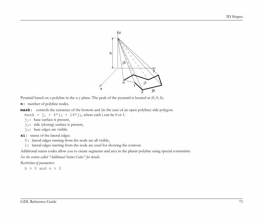
3D Shapes
GDL Reference Guide 75
x
y
z
j1
j3
j51
2
n
h
Pyramid based on a polyline in the x-y plane. The peak of the pyramid is located at (0, 0, h).n: number of polyline nodes.mask: controls the existence of the bottom and (in the case of an open polyline) side polygon.mask = j1 + 4*j3 + 16*j5, where each j can be 0 or 1.j1: base surface is present,j3: side (closing) surface is present,j5: base edges are visible.
si: status of the lateral edges.0: lateral edges starting from the node are all visible,1: lateral edges starting from the node are used for showing the contour.
Additional status codes allow you to create segments and arcs in the planar polyline using special constraints.See the section called “Additional Status Codes” for details.Restriction of parameters:h > 0 and n > 2

3D Shapes
GDL Reference Guide 76
Example:
PYRAMID 4, 1.5, 1+4+16, -2, -2, 0, -2, 2, 0, 2, 2, 0, 2, -2, 0PYRAMID 4, 4, 21, -1, -1, 0, 1, -1, 0, 1, 1, 0, -1, 1, 0for i = 1 to 4 ! four peaks ADD -1.4, -1.4, 0 PYRAMID 4, 1.5, 21, -0.25, -0.25, 0, 0.25, -0.25, 0, 0.25, 0.25, 0, -0.25, 0.25, 0 DEL 1 ROTZ 90next idel 4
REVOLVEREVOLVE n, alpha, mask, x1, y1, s1, ..., xn, yn, sn

3D Shapes
GDL Reference Guide 77
j6
j1
j3
j2
j4
1
n
Z
2
Y
j5
alpha
Surface generated by rotating a polyline defined in the x-y plane around the x axis. The profile polyline cannot contain holes.n: number of polyline nodes.alpha: rotation angle in degreesmask: controls the existence of the bottom, top and (in the case of alpha < 360°) side polygons.mask = j1 + 2*j2 + 4*j3 + 8*j4 + 16*j5 + 32*j6 + 64*j7 + 128*j8 + 256*j9, where each j can be 0 or 1.j1: closing disc at first point is present,j2: closing disc at last point is present,j3: base closing side (in profile plane) is present,j4: end closing side (in revolved plane) is present,j5: base edges (in profile plane) are visible,j6: end edges (in revolved plane) are visible,j7: cross-section edges are visible, surface is articulated,j8: horizontal edge in line elimination,j9: vertical edge in line elimination.
si: status of the latitudinal arcs.0: latitudinal arcs starting from the node are all visible,

3D Shapes
GDL Reference Guide 78
1: latitudinal arcs starting from the node are used for showing the contour,2: when using ARCHICAD or Z-buffer Rendering Engine and setting Smooth Surfaces, the latitudinal edge belonging to this point definesa break. This solution is equivalent to the definition of additional nodes. The calculation is performed by the compiler. With other renderingmethods, it has the same effect as using 0.
Additional status codes allow you to create segments and arcs in the planar polyline using special constraints.See the section called “Additional Status Codes” for details.Restriction of parameters:n >= 2yi >= 0.0yi = 0.0 and yi+1 = 0.0 cannot stand at the same time(i.e., the y value of two neighboring nodes cannot be zero at the same time).
Example 1:

3D Shapes
GDL Reference Guide 79
ROTY -90REVOLVE 22, 360, 1+64, 0, 1.982, 0, 0.093, 2, 0, 0.144, 1.845, 0, 0.220, 1.701, 0, 0.318, 1.571, 0, 0.436, 1.459, 0, 0.617, 1.263, 0, 0.772, 1.045, 0, 0.896, 0.808, 0, 0.987, 0.557, 0, 1.044, 0.296, 0, 1.064, 0.030, 0, 1.167, 0.024, 0, 1.181, 0.056, 0, 1.205, 0.081, 0, 1.236, 0.096, 0, 1.270, 0.1, 0, 1.304, 0.092, 0, 1.333, 0.073, 0, 1.354, 0.045, 0, 1.364, 0.012, 0, 1.564, 0, 0
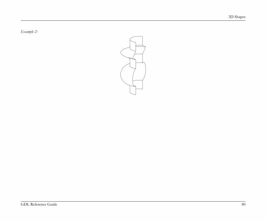
3D Shapes
GDL Reference Guide 80
Example 2:
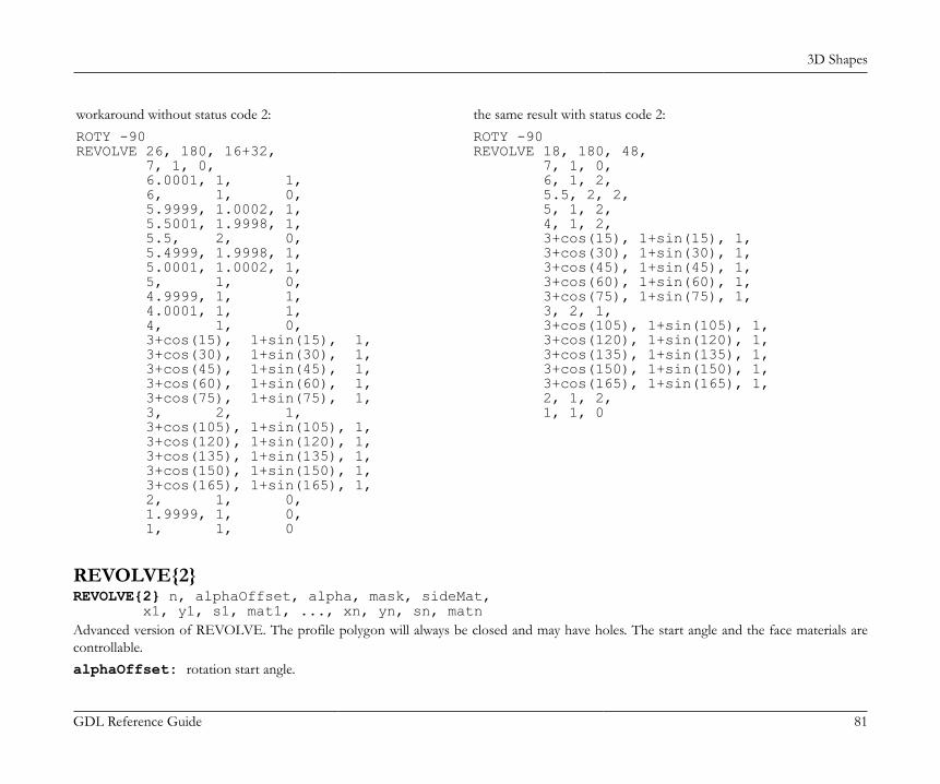
3D Shapes
GDL Reference Guide 81
workaround without status code 2: the same result with status code 2:ROTY -90REVOLVE 26, 180, 16+32, 7, 1, 0, 6.0001, 1, 1, 6, 1, 0, 5.9999, 1.0002, 1, 5.5001, 1.9998, 1, 5.5, 2, 0, 5.4999, 1.9998, 1, 5.0001, 1.0002, 1, 5, 1, 0, 4.9999, 1, 1, 4.0001, 1, 1, 4, 1, 0, 3+cos(15), 1+sin(15), 1, 3+cos(30), 1+sin(30), 1, 3+cos(45), 1+sin(45), 1, 3+cos(60), 1+sin(60), 1, 3+cos(75), 1+sin(75), 1, 3, 2, 1, 3+cos(105), 1+sin(105), 1, 3+cos(120), 1+sin(120), 1, 3+cos(135), 1+sin(135), 1, 3+cos(150), 1+sin(150), 1, 3+cos(165), 1+sin(165), 1, 2, 1, 0, 1.9999, 1, 0, 1, 1, 0
ROTY -90REVOLVE 18, 180, 48, 7, 1, 0, 6, 1, 2, 5.5, 2, 2, 5, 1, 2, 4, 1, 2, 3+cos(15), 1+sin(15), 1, 3+cos(30), 1+sin(30), 1, 3+cos(45), 1+sin(45), 1, 3+cos(60), 1+sin(60), 1, 3+cos(75), 1+sin(75), 1, 3, 2, 1, 3+cos(105), 1+sin(105), 1, 3+cos(120), 1+sin(120), 1, 3+cos(135), 1+sin(135), 1, 3+cos(150), 1+sin(150), 1, 3+cos(165), 1+sin(165), 1, 2, 1, 2, 1, 1, 0
REVOLVE{2}REVOLVE{2} n, alphaOffset, alpha, mask, sideMat, x1, y1, s1, mat1, ..., xn, yn, sn, matnAdvanced version of REVOLVE. The profile polygon will always be closed and may have holes. The start angle and the face materials arecontrollable.alphaOffset: rotation start angle.
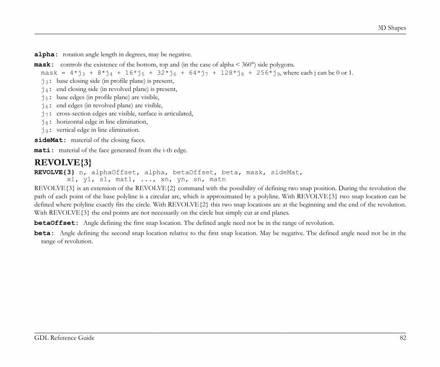
3D Shapes
GDL Reference Guide 82
alpha: rotation angle length in degrees, may be negative.mask: controls the existence of the bottom, top and (in the case of alpha < 360°) side polygons.mask = 4*j3 + 8*j4 + 16*j5 + 32*j6 + 64*j7 + 128*j8 + 256*j9, where each j can be 0 or 1.j3: base closing side (in profile plane) is present,j4: end closing side (in revolved plane) is present,j5: base edges (in profile plane) are visible,j6: end edges (in revolved plane) are visible,j7: cross-section edges are visible, surface is articulated,j8: horizontal edge in line elimination,j9: vertical edge in line elimination.
sideMat: material of the closing faces.mati: material of the face generated from the i-th edge.
REVOLVE{3}REVOLVE{3} n, alphaOffset, alpha, betaOffset, beta, mask, sideMat, x1, y1, s1, mat1, ..., xn, yn, sn, matnREVOLVE{3} is an extension of the REVOLVE{2} command with the possibility of defining two snap position. During the revolution thepath of each point of the base polyline is a circular arc, which is approximated by a polyline. With REVOLVE{3} two snap location can bedefined where polyline exactly fits the circle. With REVOLVE{2} this two snap locations are at the beginning and the end of the revolution.With REVOLVE{3} the end points are not necessarily on the circle but simply cut at end planes.betaOffset: Angle defining the first snap location. The defined angle need not be in the range of revolution.beta: Angle defining the second snap location relative to the first snap location. May be negative. The defined angle need not be in the
range of revolution.

3D Shapes
GDL Reference Guide 83
Example:
revolve{2} snap positions at ends revolve{3} custom snap positions
resol 8revolve{2} 4, 10, 335, ! alphaOffset, alpha 444, 2, 0, 4, 2, 2, 3, 4, 2, 2, 3, 6, 2, 2, 0, 6, 2, 2! reference circleresol 72revolve{2} 4, 0, 360, ! alphaOffset, alpha 444, 0, -0.01, 3.99, 2, 0, 0, 3.99, 2, 0, 0, 4, 2, 0, -0.01, 4, 2, 0
resol 8revolve{3} 4, 10, 335, ! alphaOffset, alpha 67.5, 100, ! betaOffset, beta 444, 2, 0, 4, 2, 2, 3, 4, 2, 2, 3, 6, 2, 2, 0, 6, 2, 2! reference circleresol 72revolve{2} 4, 0, 360, ! alphaOffset, alpha 444, 0, -0.01, 3.99, 2, 0, 0, 3.99, 2, 0, 0, 4, 2, 0, -0.01, 4, 2, 0

3D Shapes
GDL Reference Guide 84
REVOLVE{4}REVOLVE{4} n, alphaOffset, alpha, betaOffset, beta, mask, sideMat, x1, y1, s1, mat1, ..., xn, yn, sn, matnREVOLVE{4} is an extension of the REVOLVE{3} command with the possibility of hiding all edges.mask: controls the existence of the bottom, top and (in the case of alpha < 360°) side polygons.mask = 4*j3 + 8*j4 + 16*j5 + 32*j6 + 64*j7 + 128*j8 + 256*j9 + 512*j10 + 1024*j11, whereeach j can be 0 or 1.j3: base closing side (in profile plane) is present,j4: end closing side (in revolved plane) is present,j5: base edges (in profile plane) are visible,j6: end edges (in revolved plane) are visible,j7: cross-section edges are visible, surface is articulated,j8: horizontal edge in line elimination,j9: vertical edge in line elimination,j10: hide all edges of revolve,j11: side edge and surface is smooth in curved sections of the profile. Compatibility: introduced in ARCHICAD 21.
REVOLVE{5}REVOLVE{5}n, alphaOffset, alpha, betaOffset, beta, mask, sideMat, x1, y1, s1, mat1, ..., xn, yn, sn, matnREVOLVE{5} is an extension of the REVOLVE{4} command with the possibility of using inline material definition, that means materialsdefined in GDL script locally also can be used next to materials defined in global material definitions.
RULEDRULED n, mask, u1, v1, s1, ..., un, vn, sn, x1, y1, z1, ..., xn, yn, zn
RULED{2}RULED{2} n, mask, u1, v1, s1, ..., un, vn, sn, x1, y1, z1, ..., xn, yn, zn
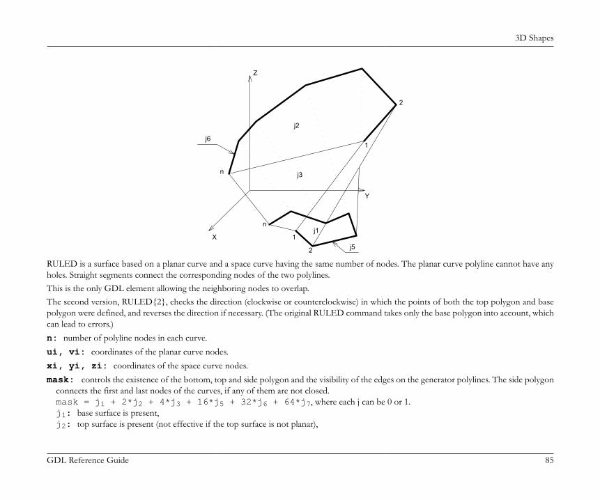
3D Shapes
GDL Reference Guide 85
j3
j61
n
j2
j51
Z
2
n
Xj1
Y
2
RULED is a surface based on a planar curve and a space curve having the same number of nodes. The planar curve polyline cannot have anyholes. Straight segments connect the corresponding nodes of the two polylines.This is the only GDL element allowing the neighboring nodes to overlap.The second version, RULED{2}, checks the direction (clockwise or counterclockwise) in which the points of both the top polygon and basepolygon were defined, and reverses the direction if necessary. (The original RULED command takes only the base polygon into account, whichcan lead to errors.)n: number of polyline nodes in each curve.ui, vi: coordinates of the planar curve nodes.xi, yi, zi: coordinates of the space curve nodes.mask: controls the existence of the bottom, top and side polygon and the visibility of the edges on the generator polylines. The side polygon
connects the first and last nodes of the curves, if any of them are not closed.mask = j1 + 2*j2 + 4*j3 + 16*j5 + 32*j6 + 64*j7, where each j can be 0 or 1.j1: base surface is present,j2: top surface is present (not effective if the top surface is not planar),
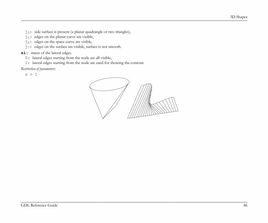
3D Shapes
GDL Reference Guide 86
j3: side surface is present (a planar quadrangle or two triangles),j5: edges on the planar curve are visible,j6: edges on the space curve are visible,j7: edges on the surface are visible, surface is not smooth.
si: status of the lateral edges.0: lateral edges starting from the node are all visible,1: lateral edges starting from the node are used for showing the contour.
Restriction of parameters:n > 1
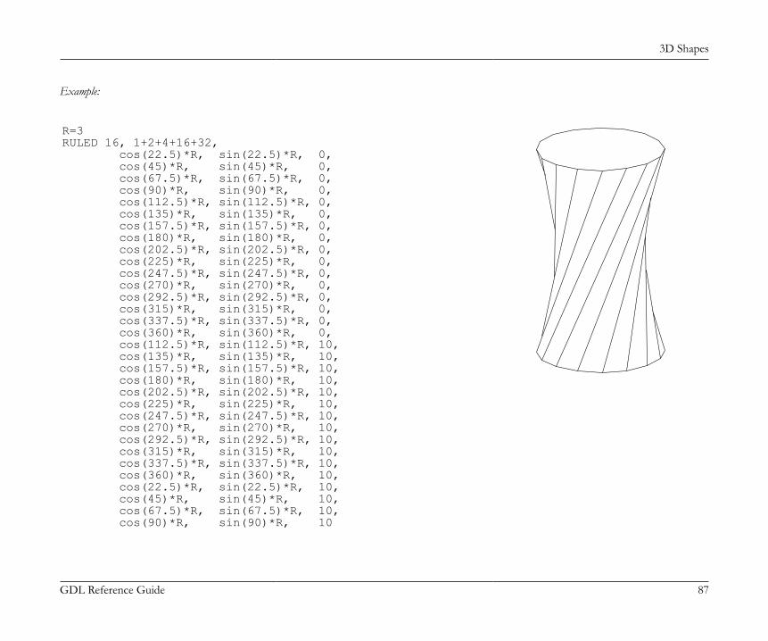
3D Shapes
GDL Reference Guide 87
Example:
R=3RULED 16, 1+2+4+16+32, cos(22.5)*R, sin(22.5)*R, 0, cos(45)*R, sin(45)*R, 0, cos(67.5)*R, sin(67.5)*R, 0, cos(90)*R, sin(90)*R, 0, cos(112.5)*R, sin(112.5)*R, 0, cos(135)*R, sin(135)*R, 0, cos(157.5)*R, sin(157.5)*R, 0, cos(180)*R, sin(180)*R, 0, cos(202.5)*R, sin(202.5)*R, 0, cos(225)*R, sin(225)*R, 0, cos(247.5)*R, sin(247.5)*R, 0, cos(270)*R, sin(270)*R, 0, cos(292.5)*R, sin(292.5)*R, 0, cos(315)*R, sin(315)*R, 0, cos(337.5)*R, sin(337.5)*R, 0, cos(360)*R, sin(360)*R, 0, cos(112.5)*R, sin(112.5)*R, 10, cos(135)*R, sin(135)*R, 10, cos(157.5)*R, sin(157.5)*R, 10, cos(180)*R, sin(180)*R, 10, cos(202.5)*R, sin(202.5)*R, 10, cos(225)*R, sin(225)*R, 10, cos(247.5)*R, sin(247.5)*R, 10, cos(270)*R, sin(270)*R, 10, cos(292.5)*R, sin(292.5)*R, 10, cos(315)*R, sin(315)*R, 10, cos(337.5)*R, sin(337.5)*R, 10, cos(360)*R, sin(360)*R, 10, cos(22.5)*R, sin(22.5)*R, 10, cos(45)*R, sin(45)*R, 10, cos(67.5)*R, sin(67.5)*R, 10, cos(90)*R, sin(90)*R, 10
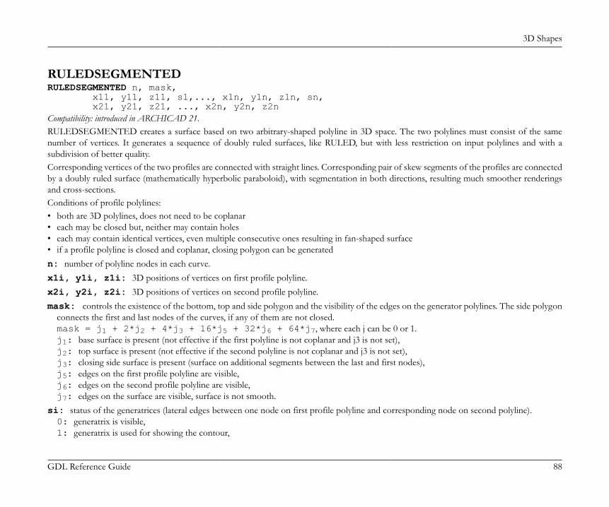
3D Shapes
GDL Reference Guide 88
RULEDSEGMENTEDRULEDSEGMENTED n, mask, x11, y11, z11, s1,..., x1n, y1n, z1n, sn, x21, y21, z21, ..., x2n, y2n, z2nCompatibility: introduced in ARCHICAD 21.RULEDSEGMENTED creates a surface based on two arbitrary-shaped polyline in 3D space. The two polylines must consist of the samenumber of vertices. It generates a sequence of doubly ruled surfaces, like RULED, but with less restriction on input polylines and with asubdivision of better quality.Corresponding vertices of the two profiles are connected with straight lines. Corresponding pair of skew segments of the profiles are connectedby a doubly ruled surface (mathematically hyperbolic paraboloid), with segmentation in both directions, resulting much smoother renderingsand cross-sections.Conditions of profile polylines:• both are 3D polylines, does not need to be coplanar• each may be closed but, neither may contain holes• each may contain identical vertices, even multiple consecutive ones resulting in fan-shaped surface• if a profile polyline is closed and coplanar, closing polygon can be generatedn: number of polyline nodes in each curve.x1i, y1i, z1i: 3D positions of vertices on first profile polyline.x2i, y2i, z2i: 3D positions of vertices on second profile polyline.mask: controls the existence of the bottom, top and side polygon and the visibility of the edges on the generator polylines. The side polygon
connects the first and last nodes of the curves, if any of them are not closed.mask = j1 + 2*j2 + 4*j3 + 16*j5 + 32*j6 + 64*j7, where each j can be 0 or 1.j1: base surface is present (not effective if the first polyline is not coplanar and j3 is not set),j2: top surface is present (not effective if the second polyline is not coplanar and j3 is not set),j3: closing side surface is present (surface on additional segments between the last and first nodes),j5: edges on the first profile polyline are visible,j6: edges on the second profile polyline are visible,j7: edges on the surface are visible, surface is not smooth.
si: status of the generatrices (lateral edges between one node on first profile polyline and corresponding node on second polyline).0: generatrix is visible,1: generatrix is used for showing the contour,
3D Shapes
GDL Reference Guide 89
2: generatrix visible and defines a break in rendering.Restriction of parameters:n > 1
Example:
RULEDSEGMENTED 4, 16+32, 0, 0, 0, 2, 1, 0, 0, 2, 1, 1, 0, 2, 1, 1, 1, 2, 0, 0, 1, 0, 1, 1, 0, 1, 2, 1, 2, 2
RULEDSEGMENTED{2}RULEDSEGMENTED{2} top_material, bottom_material, n, mask, textureMode, x11, y11, z11, s1, mat1..., x1n, y1n, z1n, sn, matn, x21, y21, z21, ..., x2n, y2n, z2nCompatibility: introduced in ARCHICAD 23.RULEDSEGMENTED{2} is an extension of the RULEDSEGMENTED command with the possibility of controlling the surface attributesof the generated surfaces in segment detail and applying custom texture projection.Additional parameters:top_material: surface attribute index of the base surface (if the first polyline is coplanar and j1+j3 are set).bottom_material: surface attribute index of the top surface (if the second polyline is coplanar and j2+j3 are set).textureMode: texture projection mode0: automatic, optimized for curved surfaces, the same as with the RULEDSEGMENTED command.1: custom, defined by the COOR command.
mati: surface attribute index of generated surface segment i.

3D Shapes
GDL Reference Guide 90
Example:
_topMatIndex = 22_bottomMatIndex = 34_segmentMatIndex_1 = 55_segmentMatIndex_2 = 44
RULEDSEGMENTED{2} _topMatIndex, _bottomMatIndex, 4, 1+2+16+32, 0, 0, 0, 0, 2, _segmentMatIndex_1, 1, 0, 0, 2, _segmentMatIndex_2, 1, 1, 0, 2, _segmentMatIndex_1, 0, 1, 0, 2, _segmentMatIndex_2, 1, 0, 1, 1, 1, 1, 0, 1, 1, 0, 0, 1
SWEEPSWEEP n, m, alpha, scale, mask, u1, v1, s1, ..., un, vn, sn, x1, y1, z1, ..., xm, ym, zmSurface generated by a polyline sweeping along a polyline space curve path.The plane of the polyline follows the path curve. The space curve has to start from the x-y plane. If this condition is not met, it is movedalong the z axis to start on the x-y plane.The cross-section at point (xi, yi, zi) is perpendicular to the space curve segment between points (xi-1, yi-1, zi-1) and (xi, yi, zi).SWEEP can be used to model the spout of a teapot and other complex shapes.n: number of polyline nodes.m: number of path nodes.alpha: incremental polyline rotation on its own plane, from one path node to the next one.scale: incremental polyline scale factor, from one path node to the next one.ui, vi: coordinates of the base polyline nodes.xi, yi, zi: coordinates of the path curve nodes.

3D Shapes
GDL Reference Guide 91
mask: controls the existence of the bottom and top polygons’ surfaces and edges.mask = j1 + 2*j2 + 4*j3 + 16*j5 + 32*j6 + 64*j7, where each j can be 0 or 1.j1: base surface is present,j2: top surface is present,j3: side surface is present,j5: base edges are visible,j6: top edges are visible,j7: cross-section edges are visible, surface is articulated.
x
y
z
1
2
n j1
j3
j5
j2j6
1
2
m
si: status of the lateral edges.0: lateral edges starting from the node are all visible,1: lateral edges starting from the node are used for showing the contour.
Additional status codes allow you to create segments and arcs in the planar polyline using special constraints.See the section called “Additional Status Codes” for details.Restriction of parameters:

3D Shapes
GDL Reference Guide 92
n > 1m > 1z1 < z2
Example:
SWEEP 4, 12, 7.5, 1, 1+2+4+16+32, -0.5, -0.25, 0, 0.5, -0.25, 0, 0.5, 0.25, 0, -0.5, 0.25, 0, 0, 0, 0.5, 0, 0, 1, 0, 0, 1.5, 0, 0, 2, 0, 0, 2.5, 0, 0, 3, 0, 0, 3.5, 0, 0, 4, 0, 0, 4.5, 0, 0, 5, 0, 0, 5.5, 0, 0, 6
3D Shapes
GDL Reference Guide 93
TUBETUBE n, m, mask, u1, w1, s1, ... un, wn, sn, x1, y1, z1, angle1, ... xm, ym, zm, anglemSurface generated by a polyline sweeping along a space curve path without distortion of the generating cross-section. The internal connectionsurfaces are rotatable in the U-W plane of the instantaneous U-V-W coordinate system.V axis: approximates the tangent of the generator curve at the corresponding point.W axis: perpendicular to the V axis and pointing upward with respect to the local z axis.U axis: perpendicular to the V and W axes and forms with them a right-hand sided Cartesian coordinate system.If the V axis is vertical, then the W direction is not correctly defined. The W axis in the previous path node is used for determining a horizontaldirection.The cross-section polygon of the tube measured at the middle of the path segments is always equal to the base polygon (u1, w1, ..., un, wn).Section polygons in joints are situated in the bisector plane of the joint segments. The base polygon must be closed.n: number of the polyline nodes.m: number of the path nodes.ui, wi: coordinates of the base polyline nodes.xi, yi, zi: coordinates of the path curve nodes.anglei: rotation angle of the cross-section.mask: controls the existence of the bottom and top polygons’ surfaces and edges.mask = j1 + 2*j2 + 16*j5 + 32*j6 + 64*j7 + 128*j8 + 512*j10 + 1024*j11 + 2048*j12 + 4096*j13,where each j can be 0 or 1.j1: base surface is present,j2: end surface is present,j5: base edges (at x2, y2, z2) are visible,j6: end edges (at xm-1, ym-1, zm-1) are visible,j7: cross-section edges are visible, surface is articulated,

3D Shapes
GDL Reference Guide 94
j8: cross-section edges are sharp, the surface smoothing will stop here in OpenGL and rendering,j10: base edges participate in line elimination (Compatibility: introduced in ARCHICAD 23.),j11: end edges participate in line elimination (Compatibility: introduced in ARCHICAD 23.),j12: longitudinal edges (which connect cross sections) participate in line elimination (Compatibility: introduced in ARCHICAD 23.),j13: edges of cross sections participate in line elimination (Compatibility: introduced in ARCHICAD 23.).
W
U
Wm
m-1
21
alpha
V
U
si: status of the lateral edges.0: lateral edges starting from the node are all visible,1: lateral edges starting from the node are used for showing the contour.2: when using ARCHICAD or Z-buffer Rendering Engine and setting Smooth Surfaces, the lateral edge belonging to this point defines abreak. This solution is equivalent to the definition of additional nodes. The calculation is performed by the compiler. With other renderingmethods, it has the same effect as using 0.
Additional status codes allow you to create segments and arcs in the planar polyline using special constraints.
Note: The path comprises two points more than the number of generated sections. The first and the last points determine the position inspace of the first and the last surfaces belonging to the TUBE. These points only play a role in determining the normal of the surfaces, theyare not actual nodes of the path. The orientation of the surfaces is the same as that of the surfaces that would be generated at the nodesnearest to the two endpoints, if the TUBE were continued in the directions indicated by these.
Restriction of parameters:n > 2 and m > 3
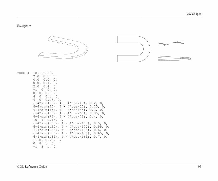
3D Shapes
GDL Reference Guide 95
Example 1:
TUBE 4, 18, 16+32, 2.0, 0.0, 0, 0.0, 0.0, 0, 0.0, 0.4, 0, 2.0, 0.4, 0, -1, 0, 0, 0, 0, 0, 0, 0, 4, 0, 0.1, 0, 6, 0, 0.15, 0, 6+4*sin(15), 4 - 4*cos(15), 0.2, 0, 6+4*sin(30), 4 - 4*cos(30), 0.25, 0, 6+4*sin(45), 4 - 4*cos(45), 0.3, 0, 6+4*sin(60), 4 - 4*cos(60), 0.35, 0, 6+4*sin(75), 4 - 4*cos(75), 0.4, 0, 10, 4, 0.45, 0, 6+4*sin(105), 4 - 4*cos(105), 0.5, 0, 6+4*sin(120), 4 - 4*cos(120), 0.55, 0, 6+4*sin(135), 4 - 4*cos(135), 0.6, 0, 6+4*sin(150), 4 - 4*cos(150), 0.65, 0, 6+4*sin(165), 4 - 4*cos(165), 0.7, 0, 6, 8, 0.75, 0, 0, 8, 1, 0, -1, 8, 1, 0
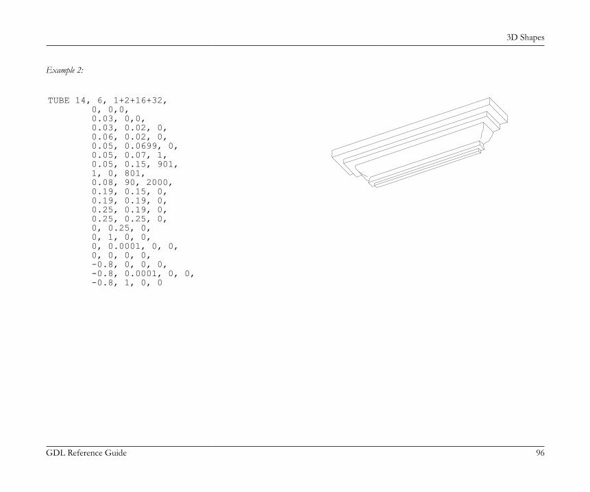
3D Shapes
GDL Reference Guide 96
Example 2:
TUBE 14, 6, 1+2+16+32, 0, 0,0, 0.03, 0,0, 0.03, 0.02, 0, 0.06, 0.02, 0, 0.05, 0.0699, 0, 0.05, 0.07, 1, 0.05, 0.15, 901, 1, 0, 801, 0.08, 90, 2000, 0.19, 0.15, 0, 0.19, 0.19, 0, 0.25, 0.19, 0, 0.25, 0.25, 0, 0, 0.25, 0, 0, 1, 0, 0, 0, 0.0001, 0, 0, 0, 0, 0, 0, -0.8, 0, 0, 0, -0.8, 0.0001, 0, 0, -0.8, 1, 0, 0

3D Shapes
GDL Reference Guide 97
Example 3:
TUBE 3, 7, 16+32, 0, 0, 0, -0.5, 0, 0, 0, 0.5, 0, 0.2, 0, -0.2, 0, 0, 0, 0, 0, 0, 0, 5, 0, 3, 0, 5, 0, 3, 4, 5, 0, 3, 4, 0, 0, 3, 3.8, -0.2, 0
TUBE{2}TUBE{2} top_material, bottom_material, cut_material, n, m, mask, u1, w1, s1, mat1, ... un, wn, sn, matn, x1, y1, z1, angle1, ... xm, ym, zm, anglemCompatibility: introduced in ARCHICAD 21. Extended version of the TUBE command:• holes can be defined within the contour base polygon• individual surfaces attribute for top, bottom polygons and cut areas• individual surface attribute for side polygons belonging to the same base polygon edgeV axis, W axis, U axis: same meaning as in the TUBE command.
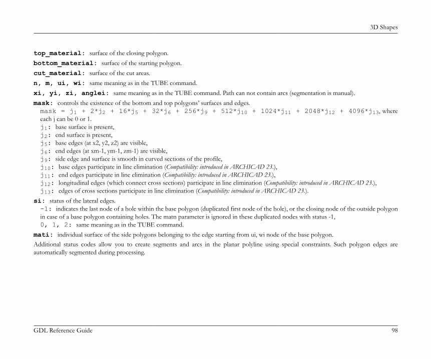
3D Shapes
GDL Reference Guide 98
top_material: surface of the closing polygon.bottom_material: surface of the starting polygon.cut_material: surface of the cut areas.n, m, ui, wi: same meaning as in the TUBE command.xi, yi, zi, anglei: same meaning as in the TUBE command. Path can not contain arcs (segmentation is manual).mask: controls the existence of the bottom and top polygons’ surfaces and edges.mask = j1 + 2*j2 + 16*j5 + 32*j6 + 256*j9 + 512*j10 + 1024*j11 + 2048*j12 + 4096*j13, whereeach j can be 0 or 1.j1: base surface is present,j2: end surface is present,j5: base edges (at x2, y2, z2) are visible,j6: end edges (at xm-1, ym-1, zm-1) are visible,j9: side edge and surface is smooth in curved sections of the profile,j10: base edges participate in line elimination (Compatibility: introduced in ARCHICAD 23.),j11: end edges participate in line elimination (Compatibility: introduced in ARCHICAD 23.),j12: longitudinal edges (which connect cross sections) participate in line elimination (Compatibility: introduced in ARCHICAD 23.),j13: edges of cross sections participate in line elimination (Compatibility: introduced in ARCHICAD 23.).
si: status of the lateral edges.-1: indicates the last node of a hole within the base polygon (duplicated first node of the hole), or the closing node of the outside polygonin case of a base polygon containing holes. The matn parameter is ignored in these duplicated nodes with status -1,0, 1, 2: same meaning as in the TUBE command.
mati: individual surface of the side polygons belonging to the edge starting from ui, wi node of the base polygon.Additional status codes allow you to create segments and arcs in the planar polyline using special constraints. Such polygon edges areautomatically segmented during processing.

3D Shapes
GDL Reference Guide 99
Example:
matEnds1 = 12matEnds2 = 24matCut = 15matOuter = 10matInner = 13
TUBE{2} matEnds1, matEnds2, matCut, 10, 4, 1 + 2 + 16 + 32,
! outside contour -0.01, 0.01, 0, matOuter, -0.01, -0.01, 0, matOuter, 0.01, -0.01, 0, matOuter, 0.01, 0.01, 0, matOuter, -0.01, 0.01, -1, matOuter,
! hole contour -0.008, 0.008, 0, matInner, -0.008, -0.008, 0, matInner, 0.008, -0.008, 0, matInner, 0.008, 0.008, 0, matInner, -0.008, 0.008, -1, matInner,
! path 0, 0, -1, 45, 0, 0, 0, 45, 0, 0, 1, 45, 0, 0, 2, 45
TUBEATUBEA n, m, mask, u1, w1, s1, ... un, wn, sn, x1, y1, z1, ... xm, ym, zm
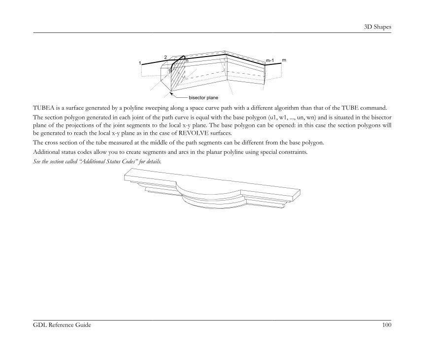
3D Shapes
GDL Reference Guide 100
bisector plane
12
m-1 m
1
n
TUBEA is a surface generated by a polyline sweeping along a space curve path with a different algorithm than that of the TUBE command.The section polygon generated in each joint of the path curve is equal with the base polygon (u1, w1, ..., un, wn) and is situated in the bisectorplane of the projections of the joint segments to the local x-y plane. The base polygon can be opened: in this case the section polygons willbe generated to reach the local x-y plane as in the case of REVOLVE surfaces.The cross section of the tube measured at the middle of the path segments can be different from the base polygon.Additional status codes allow you to create segments and arcs in the planar polyline using special constraints.See the section called “Additional Status Codes” for details.
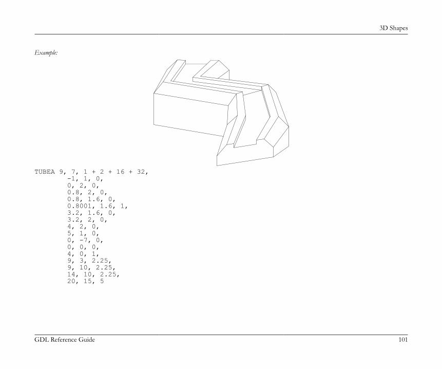
3D Shapes
GDL Reference Guide 101
Example:
TUBEA 9, 7, 1 + 2 + 16 + 32, -1, 1, 0, 0, 2, 0, 0.8, 2, 0, 0.8, 1.6, 0, 0.8001, 1.6, 1, 3.2, 1.6, 0, 3.2, 2, 0, 4, 2, 0, 5, 1, 0, 0, -7, 0, 0, 0, 0, 4, 0, 1, 9, 3, 2.25, 9, 10, 2.25, 14, 10, 2.25, 20, 15, 5
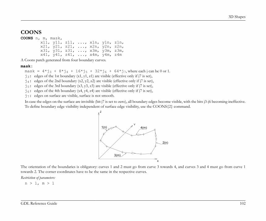
3D Shapes
GDL Reference Guide 102
COONSCOONS n, m, mask, x11, y11, z11, ..., x1n, y1n, z1n, x21, y21, z21, ..., x2n, y2n, z2n, x31, y31, z31, ..., x3m, y3m, z3m, x41, y41, z41, ..., x4m, y4m, z4mA Coons patch generated from four boundary curves.mask:mask = 4*j3 + 8*j4 + 16*j5 + 32*j6 + 64*j7, where each j can be 0 or 1.j3: edges of the 1st boundary (x1, y1, z1) are visible (effective only if j7 is set),j4: edges of the 2nd boundary (x2, y2, z2) are visible (effective only if j7 is set),j5: edges of the 3rd boundary (x3, y3, z3) are visible (effective only if j7 is set),j6: edges of the 4th boundary (x4, y4, z4) are visible (effective only if j7 is set),j7: edges on surface are visible, surface is not smooth.In case the edges on the surface are invisible (bit j7 is set to zero), all boundary edges become visible, with the bits j3-j6 becoming ineffective.To define boundary edge visibility independent of surface edge visibility, use the COONS{2} command.
4(m)
2(n)
3(m)
1(n)
Z
Y
X
The orientation of the boundaries is obligatory: curves 1 and 2 must go from curve 3 towards 4, and curves 3 and 4 must go from curve 1towards 2. The corner coordinates have to be the same in the respective curves.Restriction of parameters:n > 1, m > 1
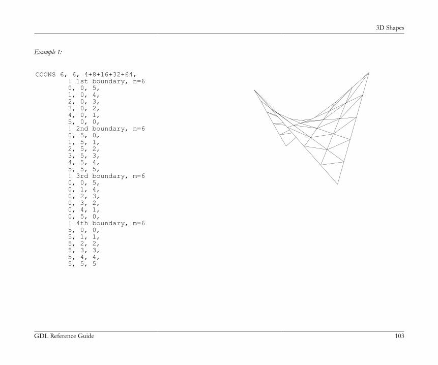
3D Shapes
GDL Reference Guide 103
Example 1:
COONS 6, 6, 4+8+16+32+64, ! 1st boundary, n=6 0, 0, 5, 1, 0, 4, 2, 0, 3, 3, 0, 2, 4, 0, 1, 5, 0, 0, ! 2nd boundary, n=6 0, 5, 0, 1, 5, 1, 2, 5, 2, 3, 5, 3, 4, 5, 4, 5, 5, 5, ! 3rd boundary, m=6 0, 0, 5, 0, 1, 4, 0, 2, 3, 0, 3, 2, 0, 4, 1, 0, 5, 0, ! 4th boundary, m=6 5, 0, 0, 5, 1, 1, 5, 2, 2, 5, 3, 3, 5, 4, 4, 5, 5, 5
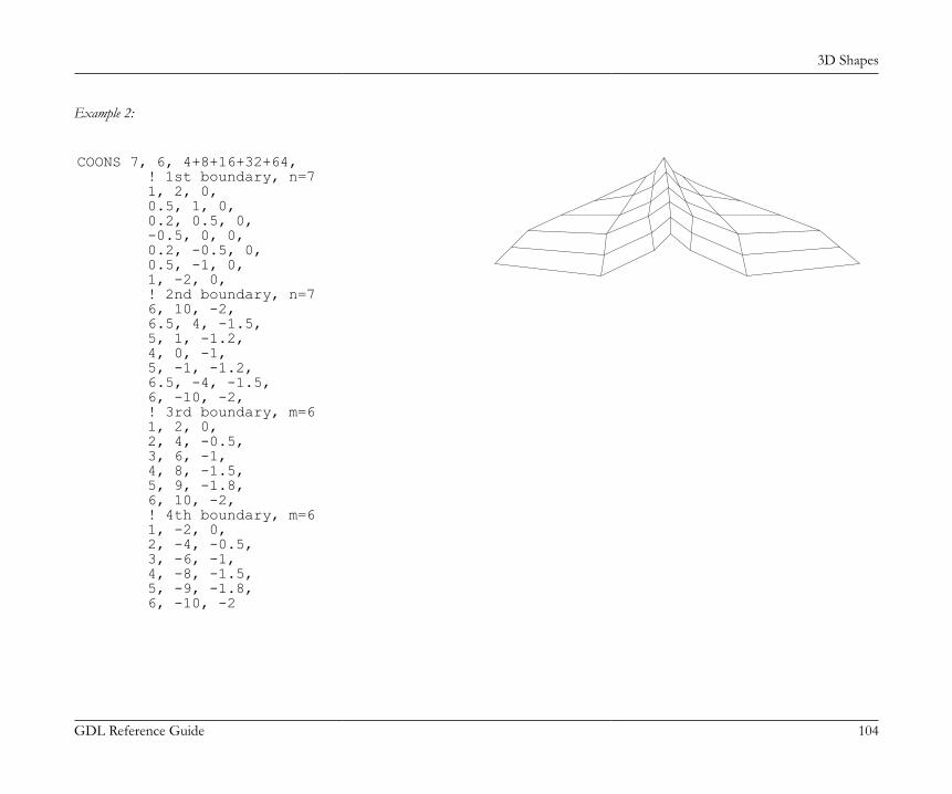
3D Shapes
GDL Reference Guide 104
Example 2:
COONS 7, 6, 4+8+16+32+64, ! 1st boundary, n=7 1, 2, 0, 0.5, 1, 0, 0.2, 0.5, 0, -0.5, 0, 0, 0.2, -0.5, 0, 0.5, -1, 0, 1, -2, 0, ! 2nd boundary, n=7 6, 10, -2, 6.5, 4, -1.5, 5, 1, -1.2, 4, 0, -1, 5, -1, -1.2, 6.5, -4, -1.5, 6, -10, -2, ! 3rd boundary, m=6 1, 2, 0, 2, 4, -0.5, 3, 6, -1, 4, 8, -1.5, 5, 9, -1.8, 6, 10, -2, ! 4th boundary, m=6 1, -2, 0, 2, -4, -0.5, 3, -6, -1, 4, -8, -1.5, 5, -9, -1.8, 6, -10, -2
3D Shapes
GDL Reference Guide 105
COONS{2}COONS{2} n, m, mask, x11, y11, z11, ..., x1n, y1n, z1n, x21, y21, z21, ..., x2n, y2n, z2n, x31, y31, z31, ..., x3m, y3m, z3m, x41, y41, z41, ..., x4m, y4m, z4mCOONS{2} is an extension of the the COONS command with the possibility of setting the visibility of surface and boundary edgesindependently.mask:mask = 4*j3 + 8*j4 + 16*j5 + 32*j6 + 64*j7, where each j can be 0 or 1.j3: edges of the 1st boundary (x1, y1, z1) are visible,j4: edges of the 2nd boundary (x2, y2, z2) are visible,j5: edges of the 3rd boundary (x3, y3, z3) are visible,j6: edges of the 4th boundary (x4, y4, z4) are visible,j7: edges on surface are visible, surface is not smooth.
MASSMASS top_material, bottom_material, side_material, n, m, mask, h, x1, y1, z1, s1, ... xn, yn, zn, sn, xn+1, yn+1, zn+1, sn+1, ... xn+m, yn+m, zn+m, sn+mThe equivalent of the shape generated by the Mesh tool in ARCHICAD.top_material, bottom_material, side_material: name/index of the top, bottom and side materials.n: the number of nodes in the mass polygon.m: the number of nodes on the ridges.h: the height of the skirt (can be negative).xi, yi, zi: the coordinates of the nodes.mask:
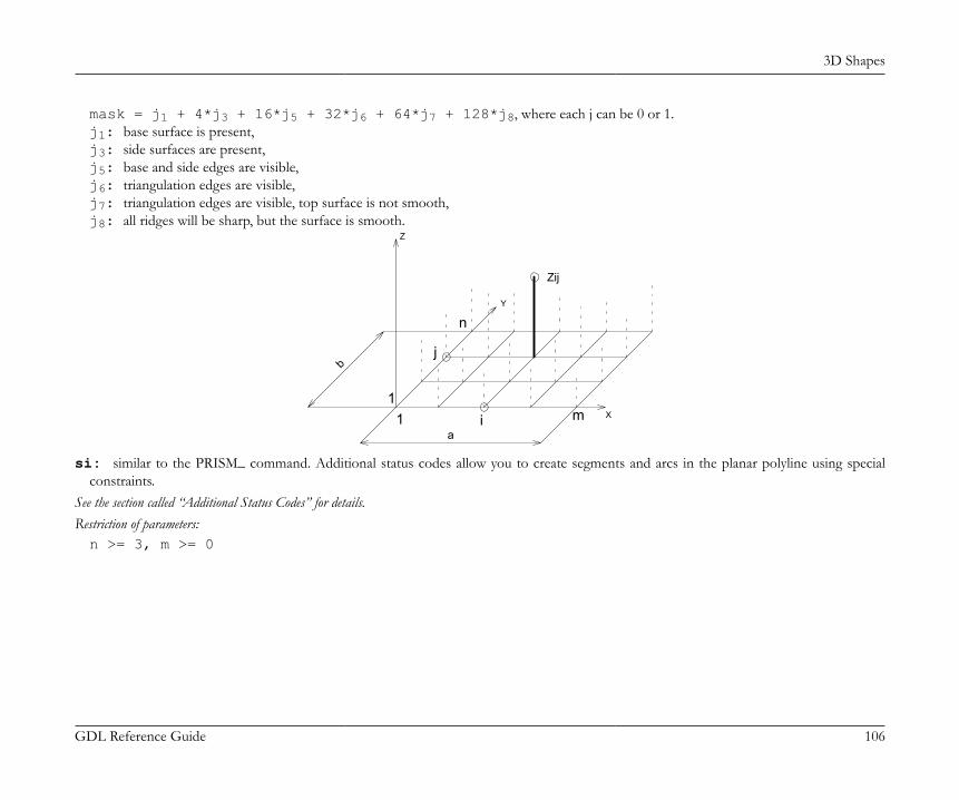
3D Shapes
GDL Reference Guide 106
mask = j1 + 4*j3 + 16*j5 + 32*j6 + 64*j7 + 128*j8, where each j can be 0 or 1.j1: base surface is present,j3: side surfaces are present,j5: base and side edges are visible,j6: triangulation edges are visible,j7: triangulation edges are visible, top surface is not smooth,j8: all ridges will be sharp, but the surface is smooth.
i
n
m1
Y
Zij
1
Z
X
jb
a
si: similar to the PRISM_ command. Additional status codes allow you to create segments and arcs in the planar polyline using specialconstraints.
See the section called “Additional Status Codes” for details.Restriction of parameters:n >= 3, m >= 0

3D Shapes
GDL Reference Guide 107
Example:
MASS "Surf-White", "Surf-White", "Surf-White", 15, 12, 117, -5.0, 0, 12, 0, 15, 8, 12, 0, 15, 8, 0, 0, 15, 13, 0, 0, 13, 16, 0, 0, 13, 19, 0, 0, 13, 23, 0, 0, 13, 24, 0, 0, 15, 24, 12, 0, 15, 28, 12, 0, 15, 28, 20, 8, 13, 28, 22, 8, 15, 0, 22, 8, 15, 0, 20, 8, 13, 0, 12, 0, -1, 0, 22, 8, 0, 28, 22, 8, -1, 23, 17, 5, 0, 23, 0, 5, -1, 13, 13, 1, 0, 13, 0, 1, -1, 16, 0, 7, 0, 16, 19, 7, -1, 0, 20, 8, 0, 28, 20, 8, -1, 19, 17, 5, 0, 19, 0, 5, -1
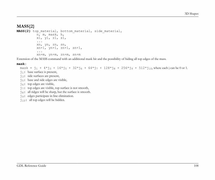
3D Shapes
GDL Reference Guide 108
MASS{2}MASS{2} top_material, bottom_material, side_material, n, m, mask, h, x1, y1, z1, s1, ... xn, yn, zn, sn, xn+1, yn+1, zn+1, sn+1, ... xn+m, yn+m, zn+m, sn+mExtension of the MASS command with an additional mask bit and the possibility of hiding all top edges of the mass.mask:mask = j1 + 4*j3 + 16*j5 + 32*j6 + 64*j7 + 128*j8 + 256*j9 + 512*j10, where each j can be 0 or 1.j1: base surface is present,j3: side surfaces are present,j5: base and side edges are visible,j6: top edges are visible,j7: top edges are visible, top surface is not smooth,j8: all ridges will be sharp, but the surface is smooth.j9: edges participate in line elimination.j10: all top edges will be hidden.

3D Shapes
GDL Reference Guide 109
Example:
PEN 1mat = IND (MATERIAL, "Metal-Aluminium")FOR i=1 TO 2 STEP 1 MASS{2} mat, mat, mat, 5, 0, 1+4+16+32+64+256, -1, 0, 0, 0, 15, 2, 0, 0, 15, 2, 2, 0, 15, 0, 2, 0, 15, 0, 0, 0, -1 BODY -1 ADDX 2NEXT i
POLYROOFPOLYROOF defaultMat, k, m, n, offset, thickness, applyContourInsidePivot, z_1, ..., z_k, pivotX_1, pivotY_1, pivotMask_1, roofAngle_11, gableOverhang_11, topMat_11, bottomMat_11, ... roofAngle_1k, gableOverhang_1k, topMat_1k, bottomMat_1k, ... pivotX_m, pivotY_m, pivotMask_m, roofAngle_m1, gableOverhang_m1, topMat_m1, bottomMat_m1, ... roofAngle_mk, gableOverhang_mk, topMat_mk, bottomMat_mk, contourX_1, contourY_1, contourMask_1, edgeTrim_1, edgeAngle_1, edgeMat_1, ... contourX_n, contourY_n, contourMask_n, edgeTrim_n, edgeAngle_n, edgeMat_nThe command creates a possibly multi-level roof in which the geometry is controlled by multiple parameters, most importantly the roof anglesand two polygons: a pivot polygon and a contour polygon. At the pivot polygon, the roof is slanted at the roof angle. It ascends until it either

3D Shapes
GDL Reference Guide 110
reaches the height of the next level or until it is eliminated by its sides encountering one another. It also descends downwards, until it reachesthe contour polygon, which cuts off parts of the roof outside of it. The contour polygon can also be used to cut holes in the roof.defaultMat: the numeric index of the "inner" material of the roof. This material becomes visible at gables and at cut surfaces, e.g., if
the roof is cut by a plane.k: the number of levels.m: the number of pivot polygon vertices.n: the number of contour polygon vertices.offset: an offset for the thickness of the roof.thickness: the thickness of the roof.applyContourInsidePivot: if set to 0, the outer contour polygon is only applied below the pivot polygon plane. If set to 1, the
outer contour polygon is applied both above and below the pivot polygon plane. The 0 setting may be used to prevent the contour polygonfrom cutting off gables that lean outwards.
z_i: the Z coordinate of a level.pivotX_i, pivotY_i: coordinates of the pivot polygon vertices.pivotMask_i:0: marks a normal vertex,-1: marks the end of the current pivot subpolygon (outer contour or hole). Data for such a vertex must be a copy of the data for the firstvertex of the subpolygon. A polygon must always be closed with a mask value of -1, even if there are no holes inside it.
roofAngle_i: angle of slant for a pivot edge on a given level. If the angle >= 90, that part of the roof becomes a gable.gableOverhang_i: at the sides of a gable, the roof can extend over a lower level of itself. The amount of this can be controlled by this
parameter, which has effect only on gables (roofAngle >= 90) that are at least on the second level of the roof.topMat_i, bottomMat_i: the numeric index of the materials for the top and bottom of the roof.contourX_i, contourY_i: coordinates of the contour polygon vertices.contourMask_i:0: marks a normal vertex,-1: marks the end of the current contour subpolygon (outer contour or hole). Data for such a vertex must be a copy of the data for thefirst vertex of the subpolygon. A polygon must always be closed with a mask value of -1, even if there are no holes inside it.
edgeTrim_i: specifies the way the edge is trimmed by the contour polygon. Possible values are:0: Vertical,
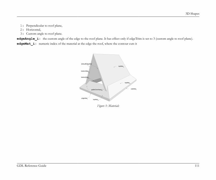
3D Shapes
GDL Reference Guide 111
1: Perpendicular to roof plane,2: Horizontal,3: Custom angle to roof plane.
edgeAngle_i: the custom angle of the edge to the roof plane. It has effect only if edgeTrim is set to 3 (custom angle to roof plane).edgeMat_i: numeric index of the material at the edge the roof, where the contour cuts it
defaultEdgeMat
bottomMat42
bottomMat41
topMat22
topMat21
sideMat2 gableOverhang
12
topMat11
edgeMat1
Figure 1: Materials
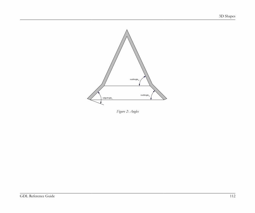
3D Shapes
GDL Reference Guide 112
roofAngle22
roofAngle21
edgeAngle4
Figure 2: Angles

3D Shapes
GDL Reference Guide 113
Example:POLYROOF "Paint-01", 2, 5, 5, 0, 0.2, 0, ! Start of z values 2.7, 3.2, ! Start of pivot polygon 2, 8, 0, 45, 0, ind(material, "Paint-01"), ind(material, "Paint-01"), 90, 0.5, ind(material, "Paint-01"), ind(material, "Paint-01"), 2, 3, 0, 45, 0, ind(material, "Paint-01"), ind(material, "Paint-01"), 65, 0, ind(material, "Paint-01"), ind(material, "Paint-01"), 10, 3, 0, 45, 0, ind(material, "Paint-01"), ind(material, "Paint-01"), 65, 0, ind(material, "Paint-01"), ind(material, "Paint-01"), 10, 8, 0, 45, 0, ind(material, "Paint-01"), ind(material, "Paint-01"), 65, 0, ind(material, "Paint-01"), ind(material, "Paint-01"), 2, 8, -1, 45, 0, ind(material, "Paint-01"), ind(material, "Paint-01"), 90, 0.5, ind(material, "Paint-01"), ind(material, "Paint-01"), ! Start of contour polygon 1.5, 8.5, 0, 0, 0, ind(material, "Paint-01"), 1.5, 2.5, 0, 0, 0, ind(material, "Paint-01"), 10.5, 2.5, 0, 0, 0, ind(material, "Paint-01"), 10.5, 8.5, 0, 0, 0, ind(material, "Paint-01"), 1.5, 8.5, -1, 0, 0, ind(material, "Paint-01")Output: see Figure 1
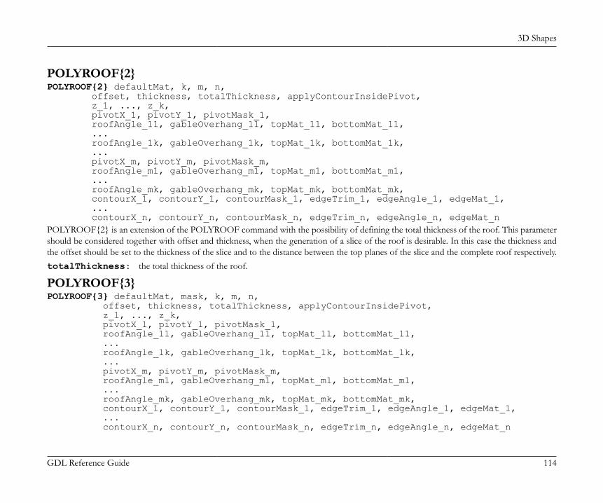
3D Shapes
GDL Reference Guide 114
POLYROOF{2}POLYROOF{2} defaultMat, k, m, n, offset, thickness, totalThickness, applyContourInsidePivot, z_1, ..., z_k, pivotX_1, pivotY_1, pivotMask_1, roofAngle_11, gableOverhang_11, topMat_11, bottomMat_11, ... roofAngle_1k, gableOverhang_1k, topMat_1k, bottomMat_1k, ... pivotX_m, pivotY_m, pivotMask_m, roofAngle_m1, gableOverhang_m1, topMat_m1, bottomMat_m1, ... roofAngle_mk, gableOverhang_mk, topMat_mk, bottomMat_mk, contourX_1, contourY_1, contourMask_1, edgeTrim_1, edgeAngle_1, edgeMat_1, ... contourX_n, contourY_n, contourMask_n, edgeTrim_n, edgeAngle_n, edgeMat_nPOLYROOF{2} is an extension of the POLYROOF command with the possibility of defining the total thickness of the roof. This parametershould be considered together with offset and thickness, when the generation of a slice of the roof is desirable. In this case the thickness andthe offset should be set to the thickness of the slice and to the distance between the top planes of the slice and the complete roof respectively.totalThickness: the total thickness of the roof.
POLYROOF{3}POLYROOF{3} defaultMat, mask, k, m, n, offset, thickness, totalThickness, applyContourInsidePivot, z_1, ..., z_k, pivotX_1, pivotY_1, pivotMask_1, roofAngle_11, gableOverhang_11, topMat_11, bottomMat_11, ... roofAngle_1k, gableOverhang_1k, topMat_1k, bottomMat_1k, ... pivotX_m, pivotY_m, pivotMask_m, roofAngle_m1, gableOverhang_m1, topMat_m1, bottomMat_m1, ... roofAngle_mk, gableOverhang_mk, topMat_mk, bottomMat_mk, contourX_1, contourY_1, contourMask_1, edgeTrim_1, edgeAngle_1, edgeMat_1, ... contourX_n, contourY_n, contourMask_n, edgeTrim_n, edgeAngle_n, edgeMat_n
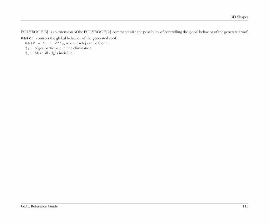
3D Shapes
GDL Reference Guide 115
POLYROOF{3} is an extension of the POLYROOF{2} command with the possibility of controlling the global behavior of the generated roof.mask: controls the global behavior of the generated roof.mask = j1 + 2*j2, where each j can be 0 or 1.j1: edges participate in line elimination.j2: Make all edges invisible.

3D Shapes
GDL Reference Guide 116
Example:
pen 1mat = IND (MATERIAL, "Metal-Aluminium")a = -0.4242640691048 : b = 4.424264068326c = 6.424264068326POLYROOF{3} mat,1, 2, 5, 5, 0, 0.3, 0.3, 1, 0, 1, a, b, 0, 45, 0, mat, mat, 90, 0, mat, mat, a, a, 0, 45, 0, mat, mat, 90, 0, mat, mat, c, a, 0, 45, 0, mat, mat, 90, 0, mat, mat, c, b, 0, 45, 0, mat, mat, 90, 0, mat, mat, a, b, -1,45, 0, mat, mat, 90, 0, mat, mat, -0.8, -0.8, 0, 2, 0, mat, 6.8, -0.8, 0, 2, 0, mat, 6.8, 4.8, 0, 2, 0, mat, -0.8, 4.8, 0, 2, 0, mat, -0.8, -0.8, -1, 2, 0, mat
a = 0.1514718617904 : b = 3.848528136652c = 5.848528136652 : q = 0.5757359305057w = 5.424264067936 : e = 3.424264056692POLYROOF{3} mat,1, 1, 5, 5, 0, 0.3, 0.3, 1, 0.5757359312847, a, b, 0, 45, 0, mat, mat, a, a, 0, 45, 0, mat, mat, c, a, 0, 45, 0, mat, mat, c, b, 0, 45, 0, mat, mat, a, b, -1, 45, 0, mat, mat, q, q, 0, 0, 0, mat, w, q, 0, 0, 0, mat, w, e, 0, 0, 0, mat, q, e, 0, 0, 0, mat, q, q, -1, 0, 0, mat

3D Shapes
GDL Reference Guide 117
POLYROOF{4}POLYROOF{4} defaultMat, mask, k, m, n, offset, thickness, totalThickness, applyContourInsidePivot, z_1, ..., z_k, pivotX_1, pivotY_1, pivotMask_1, roofAngle_11, gableOverhang_11, topMat_11, bottomMat_11, ... roofAngle_1k, gableOverhang_1k, topMat_1k, bottomMat_1k, ... pivotX_m, pivotY_m, pivotMask_m, roofAngle_m1, gableOverhang_m1, topMat_m1, bottomMat_m1, ... roofAngle_mk, gableOverhang_mk, topMat_mk, bottomMat_mk, contourX_1, contourY_1, contourMask_1, edgeTrim_1, edgeAngle_1, edgeMat_1, ... contourX_n, contourY_n, contourMask_n, edgeTrim_n, edgeAngle_n, edgeMat_nPOLYROOF{4} is an extension of the POLYROOF{3} command with the possibility of using inline material definition, that means materialsdefined in GDL script locally also can be used next to materials defined in global material definitions.
EXTRUDEDSHELLEXTRUDEDSHELL topMat, bottomMat, sideMat_1, sideMat_2, sideMat_3, sideMat_4, defaultMat, n, offset, thickness, flipped, trimmingBody, x_tb, y_tb, x_te, y_te, topz, tangle, x_bb, y_bb, x_be, y_be, bottomz, bangle, preThickenTran_11, preThickenTran_12, preThickenTran_13, preThickenTran_14, preThickenTran_21, preThickenTran_22, preThickenTran_23, preThickenTran_24, preThicakenTran_31, preThickenTran_32, preThickenTran_33, preThickenTran_34, x_1, y_1, s_1, ... x_n, y_n, s_nSurface created by first extruding a polyline, then adding thickness to it.topMat, bottomMat, sideMat_1, sideMat_2, sideMat_3, sideMat_4: Materials on the top, bottom and four sides
of the object.defaultMat: the numeric index of the "inner" material of the object. This material becomes visible at cut surfaces, e.g., if the object
is cut by a plane.

3D Shapes
GDL Reference Guide 118
n: number of profile base polyline vertices.offset: an offset for the thickness of the shell. Cannot be negative.thickness: the thickness of the shell.flipped:1: if the shell should be flipped,0: otherwise.
trimmingBody:1: if the shell is to be closed for trimming purposes,0: otherwise.
x_tb, y_tb, x_te, y_te, topz, tangle: Specify the top plane of the extrusion. The meaning of the parameters is the sameas for the SPRISM_{2} command.
x_bb, y_bb, x_be, y_be, bottomz, bangle: Specify the bottom plane of the extrusion. The meaning of the parametersis the same as for the SPRISM_{2} command.
preThickenTran_i: a transformation executed before thickening. See the XFORM command for the meaning of parameters.x_i, y_i, s_i: X and Y coordinates and status values for the base profile polyline. See the EXTRUDE command for details. The
visibility of the sides cannot be controlled with the status.
EXTRUDEDSHELL{2}EXTRUDEDSHELL{2} topMat, bottomMat, sideMat_1, sideMat_2, sideMat_3, sideMat_4, defaultMat, n, status, offset, thickness, flipped, trimmingBody, x_tb, y_tb, x_te, y_te, topz, tangle, x_bb, y_bb, x_be, y_be, bottomz, bangle, preThickenTran_11, preThickenTran_12, preThickenTran_13, preThickenTran_14, preThickenTran_21, preThickenTran_22, preThickenTran_23, preThickenTran_24, preThicakenTran_31, preThickenTran_32, preThickenTran_33, preThickenTran_34, x_1, y_1, s_1, ... x_n, y_n, s_nEXTRUDEDSHELL{2} is an extension of the EXTRUDEDSHELL command with the possibility of hiding edges between original andthickened surface.status: Status bits:

3D Shapes
GDL Reference Guide 119
status = j1, where each j can be 0 or 1.j1: Make edges invisible between original and thickened surface.
Example:
EXTRUDEDSHELL "Paint-02", "Surf-Stucco Yellow", "Surf-Stucco Yellow", "Surf-Stucco Yellow", "Surf-Stucco Yellow", "Surf-Stucco Yellow", "Surf-Stucco Yellow", 3, 0.00, 0.30, 0, 0, ! 2 slant planes 0.00, 0.00, 0.00, 1.00, 0.00, 0.00, 0.00, 0.00, 0.00, 1.00, -10.00, 0.00, ! transformation matrix 0.00, 0.00, 1.00, 0.00, 1.00, 0.00, 0.00, 0.00, 0.00, 1.00, 0.00, 0.00, ! profile polyline 2.00, 0.00, 15, 0.00, 2.00, 15, -2.00, 0.00, 15
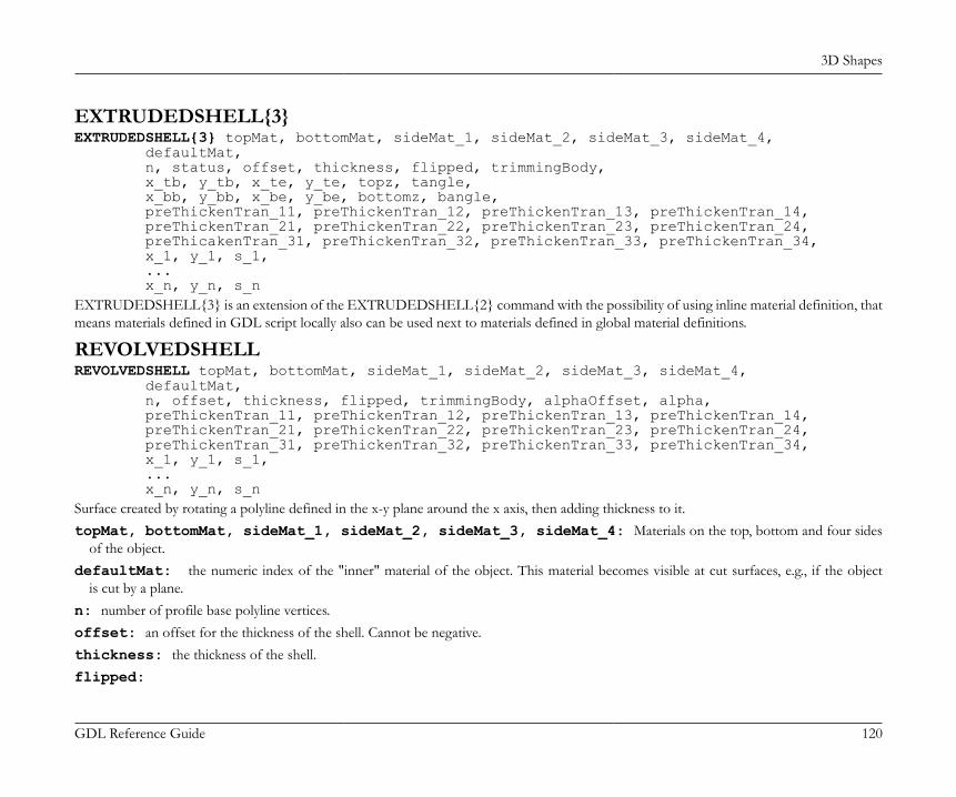
3D Shapes
GDL Reference Guide 120
EXTRUDEDSHELL{3}EXTRUDEDSHELL{3} topMat, bottomMat, sideMat_1, sideMat_2, sideMat_3, sideMat_4, defaultMat, n, status, offset, thickness, flipped, trimmingBody, x_tb, y_tb, x_te, y_te, topz, tangle, x_bb, y_bb, x_be, y_be, bottomz, bangle, preThickenTran_11, preThickenTran_12, preThickenTran_13, preThickenTran_14, preThickenTran_21, preThickenTran_22, preThickenTran_23, preThickenTran_24, preThicakenTran_31, preThickenTran_32, preThickenTran_33, preThickenTran_34, x_1, y_1, s_1, ... x_n, y_n, s_nEXTRUDEDSHELL{3} is an extension of the EXTRUDEDSHELL{2} command with the possibility of using inline material definition, thatmeans materials defined in GDL script locally also can be used next to materials defined in global material definitions.
REVOLVEDSHELLREVOLVEDSHELL topMat, bottomMat, sideMat_1, sideMat_2, sideMat_3, sideMat_4, defaultMat, n, offset, thickness, flipped, trimmingBody, alphaOffset, alpha, preThickenTran_11, preThickenTran_12, preThickenTran_13, preThickenTran_14, preThickenTran_21, preThickenTran_22, preThickenTran_23, preThickenTran_24, preThickenTran_31, preThickenTran_32, preThickenTran_33, preThickenTran_34, x_1, y_1, s_1, ... x_n, y_n, s_nSurface created by rotating a polyline defined in the x-y plane around the x axis, then adding thickness to it.topMat, bottomMat, sideMat_1, sideMat_2, sideMat_3, sideMat_4: Materials on the top, bottom and four sides
of the object.defaultMat: the numeric index of the "inner" material of the object. This material becomes visible at cut surfaces, e.g., if the object
is cut by a plane.n: number of profile base polyline vertices.offset: an offset for the thickness of the shell. Cannot be negative.thickness: the thickness of the shell.flipped:

3D Shapes
GDL Reference Guide 121
1: if the shell should be flipped,0: otherwise.
trimmingBody:1: if the shell is to be closed for trimming purposes,0: otherwise.
alphaOffset: the sweep start angle.alpha: the sweep angle length in degrees, may be negative.preThickenTran_i: a transformation executed before thickening. See the XFORM command for the meaning of parameters.x_i, y_i, s_i: X and Y coordinates and status values for the base profile polyline. See the EXTRUDE command for details. The
visibility of the sides cannot be controlled with the status.
REVOLVEDSHELL{2}REVOLVEDSHELL{2} topMat, bottomMat, sideMat_1, sideMat_2, sideMat_3, sideMat_4, defaultMat, n, status, offset, thickness, flipped, trimmingBody, alphaOffset, alpha, preThickenTran_11, preThickenTran_12, preThickenTran_13, preThickenTran_14, preThickenTran_21, preThickenTran_22, preThickenTran_23, preThickenTran_24, preThickenTran_31, preThickenTran_32, preThickenTran_33, preThickenTran_34, x_1, y_1, s_1, ... x_n, y_n, s_nREVOLVEDSHELL{2} is an extension of the REVOLVEDSHELL command with the possibility of hiding edges of surfaces, and edgesbetween original and thickened surface.status: Status bits:status = j1 + 2*j2, where each j can be 0 or 1.j1: Make edges invisible between original and thickened surface.j2: Make edges invisible on surfaces.

3D Shapes
GDL Reference Guide 122
Example:REVOLVEDSHELL "Paint-02", "Surf-Stucco Yellow", "Surf-Stucco Yellow", "Surf-Stucco Yellow", "Surf-Stucco Yellow", "Surf-Stucco Yellow", "Surf-Stucco Yellow", 2, 0.00, 0.30, 0, 0, 0.00, 270.00, ! transformation matrix 0.00, 0.00, -1.00, 0.00, 0.00, 1.00, 0.00, 0.00, 1.00, 0.00, 0.00, 0.00, ! profile polyline 4.00, 0.00, 2, 0.00, 4.00, 2

3D Shapes
GDL Reference Guide 123
REVOLVEDSHELL{3}REVOLVEDSHELL{3} topMat, bottomMat, sideMat_1, sideMat_2, sideMat_3, sideMat_4, defaultMat, n, status, offset, thickness, flipped, trimmingBody, alphaOffset, alpha, preThickenTran_11, preThickenTran_12, preThickenTran_13, preThickenTran_14, preThickenTran_21, preThickenTran_22, preThickenTran_23, preThickenTran_24, preThickenTran_31, preThickenTran_32, preThickenTran_33, preThickenTran_34, x_1, y_1, s_1, ... x_n, y_n, s_nREVOLVEDSHELL{3} is an extension of the REVOLVEDSHELL{2} command with the possibility of using inline material definition, thatmeans materials defined in GDL script locally also can be used next to materials defined in global material definitions.
REVOLVEDSHELLANGULARREVOLVEDSHELLANGULAR topMat, bottomMat, sideMat_1, sideMat_2, sideMat_3, sideMat_4, defaultMat, n, offset, thickness, flipped, trimmingBody, alphaOffset, alpha, segmentationType, nOfSegments, preThickenTran_11, preThickenTran_12, preThickenTran_13, preThickenTran_14, preThickenTran_21, preThickenTran_22, preThickenTran_23, preThickenTran_24, preThickenTran_31, preThickenTran_32, preThickenTran_33, preThickenTran_34, x_1, y_1, s_1, ... x_n, y_n, s_nAn angular variant of the REVOLVEDSHELL command. Parameters are the same with the addition of the following extra parameters:segmentationType: Must be either 1 or 2.1: means that 360 degrees of revolution is split into nOfSegments segments,2: means that the actual revolution angle (given by the alpha parameter) is split into nOfSegments segments.
nOfSegments: Number of segments, see segmentationType parameter above.

3D Shapes
GDL Reference Guide 124
REVOLVEDSHELLANGULAR{2}REVOLVEDSHELLANGULAR{2} topMat, bottomMat, sideMat_1, sideMat_2, sideMat_3, sideMat_4, defaultMat, n, status, offset, thickness, flipped, trimmingBody, alphaOffset, alpha, segmentationType, nOfSegments, preThickenTran_11, preThickenTran_12, preThickenTran_13, preThickenTran_14, preThickenTran_21, preThickenTran_22, preThickenTran_23, preThickenTran_24, preThickenTran_31, preThickenTran_32, preThickenTran_33, preThickenTran_34, x_1, y_1, s_1, ... x_n, y_n, s_nREVOLVEDSHELLANGULAR{2} is an extension of the REVOLVEDSHELLANGULAR command with the possibility of hiding edgesof surfaces, and edges between original and thickened surface.status: Status bits:status = j1 + 2*j2, where each j can be 0 or 1.j1: Make edges invisible between original and thickened surface.j2: Make edges invisible on surfaces.
REVOLVEDSHELLANGULAR{3}REVOLVEDSHELLANGULAR{3} topMat, bottomMat, sideMat_1, sideMat_2, sideMat_3, sideMat_4, defaultMat, n, status, offset, thickness, flipped, trimmingBody, alphaOffset, alpha, segmentationType, nOfSegments, preThickenTran_11, preThickenTran_12, preThickenTran_13, preThickenTran_14, preThickenTran_21, preThickenTran_22, preThickenTran_23, preThickenTran_24, preThickenTran_31, preThickenTran_32, preThickenTran_33, preThickenTran_34, x_1, y_1, s_1, ... x_n, y_n, s_n
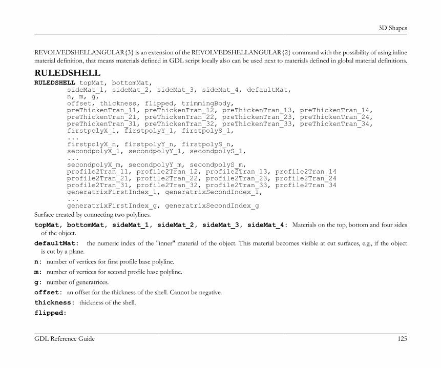
3D Shapes
GDL Reference Guide 125
REVOLVEDSHELLANGULAR{3} is an extension of the REVOLVEDSHELLANGULAR{2} command with the possibility of using inlinematerial definition, that means materials defined in GDL script locally also can be used next to materials defined in global material definitions.
RULEDSHELLRULEDSHELL topMat, bottomMat, sideMat_1, sideMat_2, sideMat_3, sideMat_4, defaultMat, n, m, g, offset, thickness, flipped, trimmingBody, preThickenTran_11, preThickenTran_12, preThickenTran_13, preThickenTran_14, preThickenTran_21, preThickenTran_22, preThickenTran_23, preThickenTran_24, preThickenTran_31, preThickenTran_32, preThickenTran_33, preThickenTran_34, firstpolyX_1, firstpolyY_1, firstpolyS_1, ... firstpolyX_n, firstpolyY_n, firstpolyS_n, secondpolyX_1, secondpolyY_1, secondpolyS_1, ... secondpolyX_m, secondpolyY_m, secondpolyS_m, profile2Tran_11, profile2Tran_12, profile2Tran_13, profile2Tran_14 profile2Tran_21, profile2Tran_22, profile2Tran_23, profile2Tran_24 profile2Tran_31, profile2Tran_32, profile2Tran_33, profile2Tran 34 generatrixFirstIndex_1, generatrixSecondIndex_1, ... generatrixFirstIndex_g, generatrixSecondIndex_gSurface created by connecting two polylines.topMat, bottomMat, sideMat_1, sideMat_2, sideMat_3, sideMat_4: Materials on the top, bottom and four sides
of the object.defaultMat: the numeric index of the "inner" material of the object. This material becomes visible at cut surfaces, e.g., if the object
is cut by a plane.n: number of vertices for first profile base polyline.m: number of vertices for second profile base polyline.g: number of generatrices.offset: an offset for the thickness of the shell. Cannot be negative.thickness: thickness of the shell.flipped:
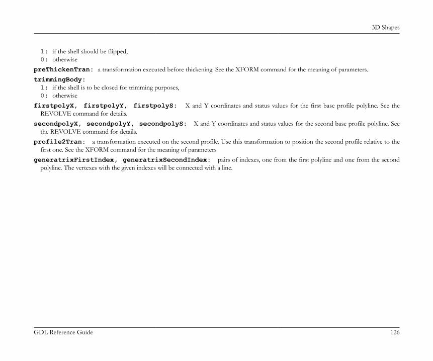
3D Shapes
GDL Reference Guide 126
1: if the shell should be flipped,0: otherwise
preThickenTran: a transformation executed before thickening. See the XFORM command for the meaning of parameters.trimmingBody:1: if the shell is to be closed for trimming purposes,0: otherwise
firstpolyX, firstpolyY, firstpolyS: X and Y coordinates and status values for the first base profile polyline. See theREVOLVE command for details.
secondpolyX, secondpolyY, secondpolyS: X and Y coordinates and status values for the second base profile polyline. Seethe REVOLVE command for details.
profile2Tran: a transformation executed on the second profile. Use this transformation to position the second profile relative to thefirst one. See the XFORM command for the meaning of parameters.
generatrixFirstIndex, generatrixSecondIndex: pairs of indexes, one from the first polyline and one from the secondpolyline. The vertexes with the given indexes will be connected with a line.
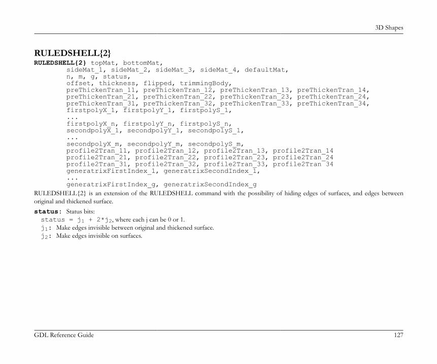
3D Shapes
GDL Reference Guide 127
RULEDSHELL{2}RULEDSHELL{2} topMat, bottomMat, sideMat_1, sideMat_2, sideMat_3, sideMat_4, defaultMat, n, m, g, status, offset, thickness, flipped, trimmingBody, preThickenTran_11, preThickenTran_12, preThickenTran_13, preThickenTran_14, preThickenTran_21, preThickenTran_22, preThickenTran_23, preThickenTran_24, preThickenTran_31, preThickenTran_32, preThickenTran_33, preThickenTran_34, firstpolyX_1, firstpolyY_1, firstpolyS_1, ... firstpolyX_n, firstpolyY_n, firstpolyS_n, secondpolyX_1, secondpolyY_1, secondpolyS_1, ... secondpolyX_m, secondpolyY_m, secondpolyS_m, profile2Tran_11, profile2Tran_12, profile2Tran_13, profile2Tran_14 profile2Tran_21, profile2Tran_22, profile2Tran_23, profile2Tran_24 profile2Tran_31, profile2Tran_32, profile2Tran_33, profile2Tran 34 generatrixFirstIndex_1, generatrixSecondIndex_1, ... generatrixFirstIndex_g, generatrixSecondIndex_gRULEDSHELL{2} is an extension of the RULEDSHELL command with the possibility of hiding edges of surfaces, and edges betweenoriginal and thickened surface.status: Status bits:status = j1 + 2*j2, where each j can be 0 or 1.j1: Make edges invisible between original and thickened surface.j2: Make edges invisible on surfaces.

3D Shapes
GDL Reference Guide 128
Example:
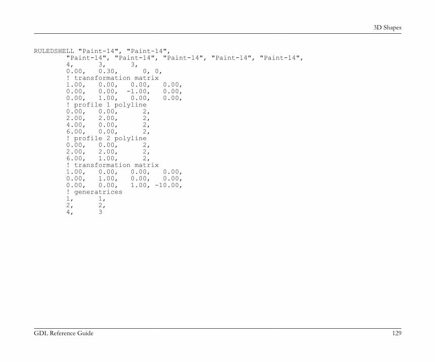
3D Shapes
GDL Reference Guide 129
RULEDSHELL "Paint-14", "Paint-14", "Paint-14", "Paint-14", "Paint-14", "Paint-14", "Paint-14", 4, 3, 3, 0.00, 0.30, 0, 0, ! transformation matrix 1.00, 0.00, 0.00, 0.00, 0.00, 0.00, -1.00, 0.00, 0.00, 1.00, 0.00, 0.00, ! profile 1 polyline 0.00, 0.00, 2, 2.00, 2.00, 2, 4.00, 0.00, 2, 6.00, 0.00, 2, ! profile 2 polyline 0.00, 0.00, 2, 2.00, 2.00, 2, 6.00, 1.00, 2, ! transformation matrix 1.00, 0.00, 0.00, 0.00, 0.00, 1.00, 0.00, 0.00, 0.00, 0.00, 1.00, -10.00, ! generatrices 1, 1, 2, 2, 4, 3
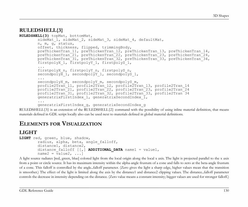
3D Shapes
GDL Reference Guide 130
RULEDSHELL{3}RULEDSHELL{3} topMat, bottomMat, sideMat_1, sideMat_2, sideMat_3, sideMat_4, defaultMat, n, m, g, status, offset, thickness, flipped, trimmingBody, preThickenTran_11, preThickenTran_12, preThickenTran_13, preThickenTran_14, preThickenTran_21, preThickenTran_22, preThickenTran_23, preThickenTran_24, preThickenTran_31, preThickenTran_32, preThickenTran_33, preThickenTran_34, firstpolyX_1, firstpolyY_1, firstpolyS_1, ... firstpolyX_n, firstpolyY_n, firstpolyS_n, secondpolyX_1, secondpolyY_1, secondpolyS_1, ... secondpolyX_m, secondpolyY_m, secondpolyS_m, profile2Tran_11, profile2Tran_12, profile2Tran_13, profile2Tran_14 profile2Tran_21, profile2Tran_22, profile2Tran_23, profile2Tran_24 profile2Tran_31, profile2Tran_32, profile2Tran_33, profile2Tran 34 generatrixFirstIndex_1, generatrixSecondIndex_1, ... generatrixFirstIndex_g, generatrixSecondIndex_gRULEDSHELL{3} is an extension of the RULEDSHELL{2} command with the possibility of using inline material definition, that meansmaterials defined in GDL script locally also can be used next to materials defined in global material definitions.
ELEMENTS FOR VISUALIZATION
LIGHTLIGHT red, green, blue, shadow, radius, alpha, beta, angle_falloff, distance1, distance2, distance_falloff [[,] ADDITIONAL_DATA name1 = value1, name2 = value2, ...]A light source radiates [red, green, blue] colored light from the local origin along the local x axis. The light is projected parallel to the x axisfrom a point or circle source. It has its maximum intensity within the alpha-angle frustum of a cone and falls to zero at the beta-angle frustumof a cone. This falloff is controlled by the angle_falloff parameter. (Zero gives the light a sharp edge, higher values mean that the transitionis smoother.) The effect of the light is limited along the axis by the distance1 and distance2 clipping values. The distance_falloff parametercontrols the decrease in intensity depending on the distance. (Zero value means a constant intensity; bigger values are used for stronger falloff.)

3D Shapes
GDL Reference Guide 131
GDL transformations affect only the starting point and the direction of the light.shadow: controls the light’s shadow casting.0: light casts no shadows,1: light casts shadows.
betaalpha
intensity
dist1
dist2
radius
Restriction of parameters:alpha <= beta <= 80°
The following parameter combinations have special meanings:radius = 0, alpha = 0, beta = 0: A point light, it radiates light in every direction and does not cast any shadows. The shadowand angle_falloff parameters are ignored, the values shadow = 0, angle_falloff = 0 are supposed.radius > 0, alpha = 0, beta = 0: A directional light with parallel beams.
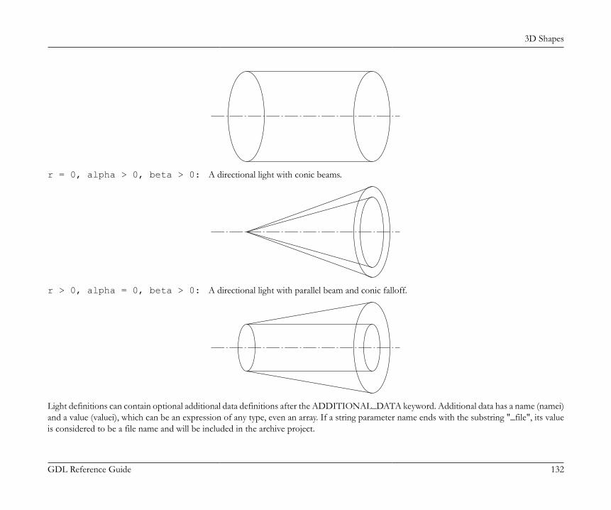
3D Shapes
GDL Reference Guide 132
r = 0, alpha > 0, beta > 0: A directional light with conic beams.
r > 0, alpha = 0, beta > 0: A directional light with parallel beam and conic falloff.
Light definitions can contain optional additional data definitions after the ADDITIONAL_DATA keyword. Additional data has a name (namei)and a value (valuei), which can be an expression of any type, even an array. If a string parameter name ends with the substring "_file", its valueis considered to be a file name and will be included in the archive project.
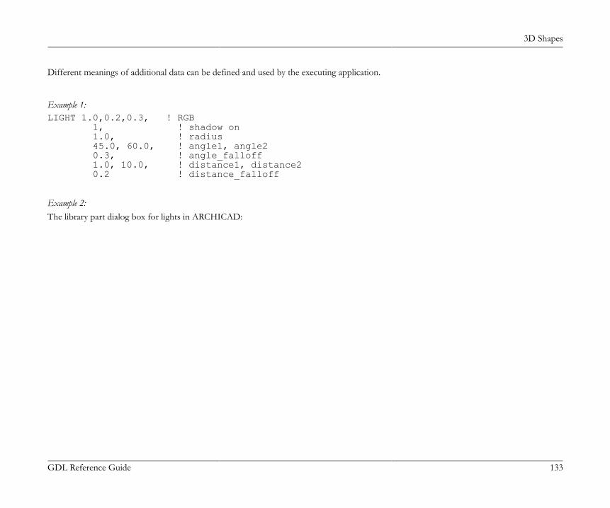
3D Shapes
GDL Reference Guide 133
Different meanings of additional data can be defined and used by the executing application.
Example 1:LIGHT 1.0,0.2,0.3, ! RGB 1, ! shadow on 1.0, ! radius 45.0, 60.0, ! angle1, angle2 0.3, ! angle_falloff 1.0, 10.0, ! distance1, distance2 0.2 ! distance_falloff
Example 2:The library part dialog box for lights in ARCHICAD:

3D Shapes
GDL Reference Guide 134
Part of the corresponding GDL script:if gs_light_switch > 0 then LIGHT gs_light_intensity/100*gs_color_red, \ gs_light_intensity/100*gs_color_green, \ gs_light_intensity/100*gs_color_blue, ! RGB ...endif
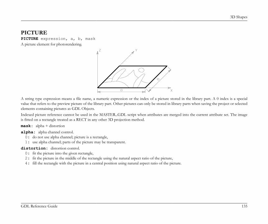
3D Shapes
GDL Reference Guide 135
PICTUREPICTURE expression, a, b, maskA picture element for photorendering.
A string type expression means a file name, a numeric expression or the index of a picture stored in the library part. A 0 index is a specialvalue that refers to the preview picture of the library part. Other pictures can only be stored in library parts when saving the project or selectedelements containing pictures as GDL Objects.Indexed picture reference cannot be used in the MASTER_GDL script when attributes are merged into the current attribute set. The imageis fitted on a rectangle treated as a RECT in any other 3D projection method.mask: alpha + distortionalpha: alpha channel control.0: do not use alpha channel; picture is a rectangle,1: use alpha channel; parts of the picture may be transparent.
distortion: distortion control.0: fit the picture into the given rectangle,2: fit the picture in the middle of the rectangle using the natural aspect ratio of the picture,4: fill the rectangle with the picture in a central position using natural aspect ratio of the picture.

3D Shapes
GDL Reference Guide 136
distortion=0 distortion=2 distortion=4
3D TEXT ELEMENTS
TEXTTEXT d, 0, expressionA 3D representation of the value of a string or numeric type expression in the current style.See the [SET] STYLE command and the DEFINE STYLE command.d: thickness of the characters in meters.In the current version of GDL, the second parameter is always zero.
Note: For compatibility with the 2D GDL script, character heights are always interpreted in millimeters in DEFINE STYLE statements.
Example 1:
DEFINE STYLE "aa" "New York", 3, 7, 0SET STYLE "aa"TEXT 0.005, 0, "3D Text"

3D Shapes
GDL Reference Guide 137
Example 2:
name = "Grand"ROTX 90ROTY -30TEXT 0.003, 0, nameADDX STW (name)/1000ROTY 60TEXT 0.003, 0, "Hotel"
RICHTEXTRICHTEXT x, y, height, 0, textblock_nameA 3D representation of a previously defined TEXTBLOCK. For more details, see the TEXTBLOCK command.x, y: X-Y coordinates of the richtext location.height: thickness of the characters in meters.textblock_name: the name of a previously defined TEXTBLOCK.In the current version of GDL, the 4th parameter is always zero.
PRIMITIVE ELEMENTSThe primitives of the 3D data structure are VERT, VECT, EDGE, PGON and BODY. The bodies are represented by their surfaces and theconnections between them. The information to execute a 3D cutaway comes from the connection information.Indexing starts with 1, and a BASE statement or any new body (implicit BASE statement) resets indices to 1. For each edge, the indices of theadjacent polygons (maximum 2) are stored. Edges’ orientations are defined by the two vertices determined first and second.Polygons are lists of edges with an orientation including the indices of the edges. These numbers can have a negative prefix. This means thatthe given edge is used in the opposite direction. Polygons can include holes. In the list of edges, a zero index indicates a new hole. Holes must
3D Shapes
GDL Reference Guide 138
not include other holes. One edge may belong to 0 to 2 polygons. In the case of closed bodies, the polygon’s orientation is correct if the edgehas different prefixes in the edge list of the two polygons.The normal vectors of the polygons are stored separately. In the case of closed bodies, they point from the inside to the outside of the body.The orientation of the edge list is counterclockwise (mathematical positive), if you are looking at it from the outside. The orientation of theholes is opposite to that of the parent polygon. Normal vectors of an open body must point to the same side of the body.To determine the inside and outside of bodies they must be closed. A simple definition for a closed body is the following: each edge has exactlytwo adjacent polygons.The efficiency of the cutting, hidden line removal or rendering algorithms is lower for open bodies. Each compound three-dimensional elementwith regular parameters is a closed body in the internal 3D data structure.Contour line searching is based on the status bits of edges and on their adjacent polygons. This is automatically set for compound curvedelements but it is up to you to specify these bits correctly in the case of primitive elements.In the case of a simplified definition (vect = 0 or status < 0 in a PGON) the primitives that are referred to by others must precede theirreference. In this case, the recommended order is:VERT (TEVE)EDGE(VECT)PGON (PIPG)COORBODYSearching for adjacent polygons by the edges is done during the execution of the BODY command.The numbering of VERTs, EDGEs, VECTs and PGONs is relative to the last (explicit or implicit) BASE statement.Status values are used to store special information about primitives. Each single bit usually has an independent meaning in the status, but thereare some exceptions.Given values can be added together. Other bit combinations than the ones given below are strictly reserved for internal use. The default foreach status is zero.
VERTVERT x, y, zA node in the x-y-z space, defined by three coordinates.
VERT{2}VERT x, y, z, hard
3D Shapes
GDL Reference Guide 139
Extension of the VERT command including a possibility to declare a node to be hard vertex. A hard vertex defines a break when renderingsmooth surfaces.x, y, z: coordinates of the node.hard:1: if the vertex should define a break when rendering smooth surfaces0: otherwise
TEVETEVE x, y, z, u, vExtension of the VERT command including a texture coordinate definition. Can be used instead of the VERT command if user-defined texturecoordinates are required instead of the automatic texture wrapping (see the COOR command).x, y, z: coordinates of a node.u, v: texture coordinates of the node (u, v) coordinates for each vertex of the current body must be specified and each vertex should have
only one texture coordinate. If VERT and TEVE statements are mixed inside a body definition, (u, v) coordinates are ineffective.
Note: The (u, v) texture coordinates are only effective in photorenderings, and not for vectorial fill mapping.
VECTVECT x, y, zDefinition of the normal vector of a polygon by three coordinates. In case of a simplified definition (vect=0 in a PGON), these statementscan be omitted.
EDGEEDGE vert1, vert2, pgon1, pgon2, statusDefinition of an edge.vert1, vert2: index of the endpoints. The vert1 and vert2 indices must be different and referenced to previously defined VERTs.pgon1, pgon2: indices of the neighboring polygons. Zero and negative values have special meanings:0: terminal or standalone edge,< 0: possible neighbors will be searched for,
status: Status bits:status = j1 + 2*j2 + 4*j3 + 8*j4 + 16*j5 + 32*j6 + 64*j7 + 262144*j19, where each j can be 0 or 1.j1: invisible edge,

3D Shapes
GDL Reference Guide 140
j2: edge of a curved surface.Reserved status bits for future use:j3: first edge of a curved surface (effective only when j2=1),j4: last edge of a curved surface (effective only when j2=1),j5: the edge is an arc segment,j6: first segment of an arc (effective only when j4=1),j7: last segment of an arc (effective only when j4=1),j19: render sharp edge between 2 curved polygons (effective only when j2=1).
PGONPGON n, vect, status, edge1, edge2, ..., edgenPolygon definition.n: number of edges in the edge list.vect: index of the normal vector. It must refer to a previously defined VECT.
Note: If vect = 0, the program will calculate the normal vector during the analysis.edge1, edge2, ..., edgen: these indices must refer to previously defined EDGEs. A zero value means the beginning or the end
of a hole definition. A negative index changes the direction of the stored normal vector or edge to the opposite in the polygon. (The storedvector or edge does not change; other polygons can refer to it using the original orientation with a positive index.)
status: Status bits:status = j1 + 2*j2 + 16*j5 + 32*j6 + 64*j7 + 4*j3 + 8*j4, where each j can be 0 or 1.j1: invisible polygon,j2: polygon of a curved surface,j5: concave polygon,j6: polygon with hole(s),j7: hole(s) are convex (effective only when j6=1),Reserved status bits for future use:j3: first polygon of a curved surface (effective only when j2=1),j4: last polygon of a curved surface (effective only when j2=1).
If the status value is negative, the engine will calculate the status of the polygon (like concave polygon or polygon with hole).n = 0 is allowed for special purposes.

3D Shapes
GDL Reference Guide 141
PGON{2}PGON{2} n, vect, status, wrap, edge_or_wrap1, ..., edge_or_wrapnThe first three parameters are similar to the ones at the PGON command.wrap: wrapping mode + projection type.0: the global wrapping mode is applied,> 0: the meaning is the same as it is in the COOR command.
edge_or_wrap1, ..., edge_or_wrapn: The number and meaning of these parameters are based on the wrap definition:edge1, ..., edgen: if wrap is 0; in this case edgen means the same as at the PGON command, and globally defined texturemapping will be applied;x1, y1, z1, x2, y2, z2, x3, y3, z3, x4, y4, z4, edge1, ..., edgen: if wrapping mode isn't 0 in wrap;in this case xi, yi, zi coordinates defining the coordinate system of the texture mapping for the polygon;edge1, u1, v1, ..., edgen, un, vn: if wrapping mode is 0 but projection type isn't 0 in wrap; in this case ui, vi texturespace coordinates are the same as at the TEVE command; the mapping will affect the currently defined polygon only.
PGON{3}PGON{3} n, vect, status, wrap_method, wrap_flags, edge_or_wrap1, ..., edge_or_wrapnThe parameters are similar to the the PGON{2} command, except wrap, which is split into two parameters wrap_method andwrap_flags. The meaning of these is the same as in the COOR{2} command.
PIPGPIPG expression, a, b, mask, n, vect, status, edge1, edge2, ..., edgenPicture polygon definition. The first four parameters are the same as in the PICTURE command; the remaining ones are the same as in thePGON command.
COORCOOR wrap, vert1, vert2, vert3, vert4Deprecated. See the COOR{3} command.Local coordinate system of a BODY for the fill and texture mapping.wrap: wrapping mode + projection typeWrapping modes:1: planar box (deprecated),

3D Shapes
GDL Reference Guide 142
2: box,3: cylindrical,4: spherical,5: same as the cylindrical fill mapping, but in rendering the top and the bottom surface will get a circular mapping,6: planar
Projection types:256: the fill always starts at the origin of the local coordinate system,1024: quadratic texture projection (recommended),2048: linear texture projection based on the average distance,4096: linear texture projection based on normal triangulation.
Note: The last three values are only effective with custom texture coordinate definitions (see the TEVE command).vert1: index of a VERT, representing the origin of the local coordinate system.vert2, vert3, vert4: indices of VERTs defining the three coordinate axes.Use a minus sign (-) before VERT indices if they are used only for defining the local coordinate system.

3D Shapes
GDL Reference Guide 143
Example: For custom texture axes:CSLAB_ "Brick-White", "Brick-White", "Brick-White", 4, 0.5, 0, 0, 0, 15, 1, 0, 0, 15, 1, 1, 1, 15, 0, 1, 1, 15BASEVERT 1, 0, 0 !#1VERT 1, 1, 1 !#2VERT 0, 0, 0 !#3VERT 1, 0, 1 !#4COOR 2, -1, -2, -3, -4BODY 1
X
Y
X'
Y'
Z
Z'
COOR{2}COOR{2} wrap_method, wrap_flags, vert1, vert2, vert3, vert4Deprecated. See the COOR{3} command.Similar to the COOR command, changing wrap to two parameters wrap_method and wrap_flags, and also extending the possibilitiesof it.
3D Shapes
GDL Reference Guide 144
wrap_method: Wrapping modes are the same as described in the the COOR command. Projection types don't apply, use wrap_flagsinstead.
wrap_flags: Wrapping flagswrap_flags = 4*j3 + 8*j4 + 16*j5 + 32*j6 + 64*j7 + 128*j8, where each j can be 0 or 1.j3: quadratic texture projection (recommended),j4: linear texture projection based on the average distance,j5: linear texture projection based on normal triangulation,j8: translate the origin of the texture coordinate system closest to the global origin in the direction of the X, Y or Z axis respectively. Forexample, j6 makes the origin translating in the direction of the X axis (along v2 - v1 vector) so that it will be the orthogonal projectionof the global origin to the line of the X axis. That is, if all j6, j7 and j8 are 1, the origin is translated into the global origin (same as ifprojection type is 256 in the the COOR command).
Note: The j3, j4 and j5 flags are only effective if wrap_method is 0 and only one of them can be 1. The j6, j7 and j8 flags are onlyeffective if wrap_method is not 0. These can be 1 at the same time in any combination.
vert1, vert2, vert3, vert4: like in the COOR command.
COOR{3}COOR{3} wrapping_method, wrap_flags, origin_X, origin_Y, origin_Z, endOfX_X, endOfX_Y, endOfX_Z, endOfY_X, endOfY_Y, endOfY_Z, endOfZ_X, endOfZ_Y, endOfZ_ZCompatibility: introduced in ARCHICAD 20.Similar to the COOR{2} command. Can be used with array parameter input (see WALL_TEXTURE_WRAP global in the section called “Wallparameters - available for Doors/Windows, listing and labels” for more).The coordinate system of the projection body is included in the COOR{3} command itself, no need to define additional vertexes in the currentBODY. Compatible with NURBS bodies (no non-NURBS primitives are needed to set up the texture coordinate system).wrap_method: Wrapping modes are the same as described in the the COOR command supplemented by NURBS based wrapping mode.
Projection types don't apply, use wrap_flags instead.1: planar box (deprecated),2: box,3: cylindrical,4: spherical,
3D Shapes
GDL Reference Guide 145
5: same as the cylindrical fill mapping, but in rendering the top and the bottom surface will get a circular mapping,6: planar,7: NURBS based, the vertices' texture coordinates are from their surface parameters, only in case of NURBS bodies.
wrap_flags: Wrapping flagswrap_flags = 4*j3 + 8*j4 + 16*j5 + 32*j6 + 64*j7 + 128*j8, where each j can be 0 or 1.j3: quadratic texture projection (recommended),j4: linear texture projection based on the average distance,j5: linear texture projection based on normal triangulation,j8: translate the origin of the texture coordinate system closest to the global origin in the direction of the X, Y or Z axis respectively. Forexample, j6 makes the origin translating in the direction of the X axis so that it will be the orthogonal projection of the global origin tothe line of the X axis. That is, if all j6, j7 and j8 are 1, the origin is translated into the global origin (opposite effect of projection type256 in the the COOR command).
Note: The j3, j4 and j5 flags are only effective if wrap_method is 0 and only one of them can be 1. The j6, j7 and j8 flags are onlyeffective if wrap_method is not 0. These can be 1 at the same time in any combination.
origin_X, origin_Y, origin_Z: node in the x-y-z space, defined by three coordinates, texture origin.endOfX_X, endOfX_Y, endOfX_Z: node in the x-y-z space, defined by three coordinates, texture mapping X direction.endOfY_X, endOfY_Y, endOfY_Z: node in the x-y-z space, defined by three coordinates, texture mapping Y direction.endOfZ_X, endOfZ_Y, endOfZ_Z: node in the x-y-z space, defined by three coordinates, texture mapping Z direction.
3D Shapes
GDL Reference Guide 146
Example: COOR{3} and equivalent COOR{2} parametrisation
COOR{3} wrapping_method, wrap_flags, origin_X, origin_Y, origin_Z, endOfX_X, endOfX_Y, endOfX_Z, endOfY_X, endOfY_Y, endOfY_Z, endOfZ_X, endOfZ_Y, endOfZ_Z
! COOR{2} equivalentBASEVERT origin_X, origin_Y, origin_Z,VERT endOfX_X, endOfX_Y, endOfX_ZVERT endOfY_X, endOfY_Y, endOfY_ZVERT endOfZ_X, endOfZ_Y, endOfZ_ZCOOR{2} wrapping_method, wrap_flags, -1, -2, -3, -4
BODYBODY statusComposes a body defined with the above primitives.status: Status bits:status = j1 + 2*j2 + 4*j3 + 32*j6 + 64*j7, where each j can be 0 or 1.j1: closed body (deprecated),j2: body including curved surface(s) (deprecated),j3: surface model: when the body is cut, no surface originates on the cutting plane,j6: body always casts shadow independently from automatic preselection algorithm,j7: body never casts shadow.If neither j6 nor j7 are set, the automatic shadow preselection is performed.See the SHADOW command.If the status value is negative, the engine will calculate the status of the body.
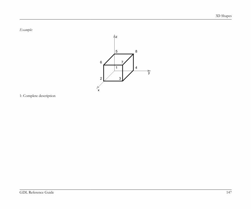
3D Shapes
GDL Reference Guide 147
Example:
x
y
z
1
2 3
4
5
6 7
8
1: Complete description

3D Shapes
GDL Reference Guide 148
VERT 0.0, 0.0, 0.0 !#1VERT 1.0, 0.0, 0.0 !#2VERT 1.0, 1.0, 0.0 !#3VERT 0.0, 1.0, 0.0 !#4VERT 0.0, 0.0, 1.0 !#5VERT 1.0, 0.0, 1.0 !#6VERT 1.0, 1.0, 1.0 !#7VERT 0.0, 1.0, 1.0 !#8EDGE 1, 2, 1, 3, 0 !#1EDGE 2, 3, 1, 4, 0 !#2EDGE 3, 4, 1, 5, 0 !#3EDGE 4, 1, 1, 6, 0 !#4EDGE 5, 6, 2, 3, 0 !#5EDGE 6, 7, 2, 4, 0 !#6EDGE 7, 8, 2, 5, 0 !#7EDGE 8, 5, 2, 6, 0 !#8EDGE 1, 5, 6, 3, 0 !#9EDGE 2, 6, 3, 4, 0 !#10EDGE 3, 7, 4, 5, 0 !#11EDGE 4, 8, 5, 6, 0 !#12VECT 1.0, 0.0, 0.0 !#1VECT 0.0, 1.0, 0.0 !#2VECT 0.0, 0.0, 1.0 !#3PGON 4, -3, 0, -1, -4, -3, -2 !#1 !VERT1,2,3,4PGON 4, 3, 0, 5, 6, 7, 8 !#2 !VERT5,6,7,8PGON 4, -2, 0, 1, 10, -5, -9 !#3 !VERT1,2,5,6PGON 4, 1, 0, 2, 11, -6, -10 !#4 !VERT2,3,6,7PGON 4, 2, 0, 3, 12, -7, -11 !#5 !VERT3,4,7,8PGON 4, -1, 0, 4, 9, -8, -12 !#6 !VERT1,4,5,8BODY 1 !CUBE2: (no direct reference to the polygons or the vectors, they will be calculated)
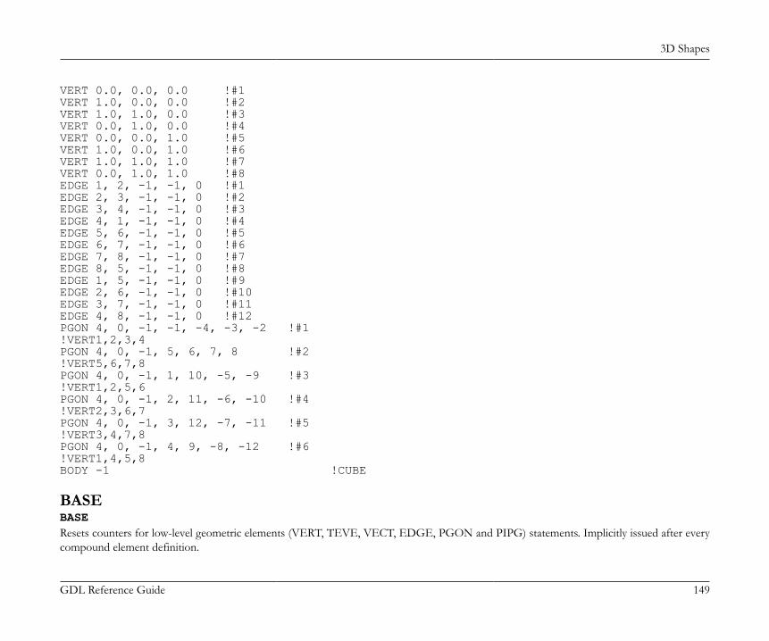
3D Shapes
GDL Reference Guide 149
VERT 0.0, 0.0, 0.0 !#1VERT 1.0, 0.0, 0.0 !#2VERT 1.0, 1.0, 0.0 !#3VERT 0.0, 1.0, 0.0 !#4VERT 0.0, 0.0, 1.0 !#5VERT 1.0, 0.0, 1.0 !#6VERT 1.0, 1.0, 1.0 !#7VERT 0.0, 1.0, 1.0 !#8EDGE 1, 2, -1, -1, 0 !#1EDGE 2, 3, -1, -1, 0 !#2EDGE 3, 4, -1, -1, 0 !#3EDGE 4, 1, -1, -1, 0 !#4EDGE 5, 6, -1, -1, 0 !#5EDGE 6, 7, -1, -1, 0 !#6EDGE 7, 8, -1, -1, 0 !#7EDGE 8, 5, -1, -1, 0 !#8EDGE 1, 5, -1, -1, 0 !#9EDGE 2, 6, -1, -1, 0 !#10EDGE 3, 7, -1, -1, 0 !#11EDGE 4, 8, -1, -1, 0 !#12PGON 4, 0, -1, -1, -4, -3, -2 !#1!VERT1,2,3,4PGON 4, 0, -1, 5, 6, 7, 8 !#2!VERT5,6,7,8PGON 4, 0, -1, 1, 10, -5, -9 !#3!VERT1,2,5,6PGON 4, 0, -1, 2, 11, -6, -10 !#4!VERT2,3,6,7PGON 4, 0, -1, 3, 12, -7, -11 !#5!VERT3,4,7,8PGON 4, 0, -1, 4, 9, -8, -12 !#6!VERT1,4,5,8BODY -1 !CUBE
BASEBASEResets counters for low-level geometric elements (VERT, TEVE, VECT, EDGE, PGON and PIPG) statements. Implicitly issued after everycompound element definition.

3D Shapes
GDL Reference Guide 150
NURBS PRIMITIVE ELEMENTSThe primitives of 3D data structure of NURBS bodies are the NURBSCURVE2D command, the NURBSCURVE3D command,the NURBSSURFACE command, the NURBSVERT command, the NURBSEDGE command, the NURBSTRIM command, theNURBSTRIMSINGULAR command, the NURBSFACE command, the NURBSLUMP command, and the NURBSBODY command.Solid NURBS bodies are represented by the boundary NURBS faces of the solid region(s), laminar surface NURBS bodies are represented bythe NURBS faces themself, wire NURBS bodies are represented by the NURBS edges. A NURBS body can have solid, laminar and wire partat the same time, a NURBS body itself is not classified into solid/surface/wire categories.Nurbs primitives can not be used in planar face bodies and non-NURBS primitives can not be used in NURBS bodies. A non-NURBSprimitive statement causes the NURBS body under construction to be finished and a new non-NURBS body to be started (implicit BODYand NURBSBODY statements).Similarly a NURBS primitive statement causes the non-NURBS body under construction to be finished and a new NURBS body to be started. Acompound statement (BRICK, CYLIND, PRISM, etc.) or a MODEL statement causes either NURBS or non-NURBS body under constructionto be finished. If a NURBSBODY statement closes a non-NURBS body or a BODY statement closes a NURBS body, the given status valuewill have no effect.Indexing of NURBS primitives starts from 1. Indexing of NURBS primitives and non-NURBS primitives (VERT, TEVE, EDGE, VECT,PGON, PIPG) are handled separately. The BASE statement resets counter for NURBS body primitives also. All primitives referenced byanother primitive should be defined before the referencing one (e.g. vertices and 3D curve of edge should be defined before the edge).The NURBSCURVE2D, NURBSCURVE3D and NURBSSURFACE statements create only geometric elements in the NURBS body whichwill not be visible themselves. A NURBS edge defines its geometric support by referencing a 3D NURBS curve, similarly a NURBS trimreferences a 2D NURBS curve and a NURBS face references a NURBS surface as its geometric support (the edge, trim and face may notextend to the whole geometric support, see details at each command description).The NURBS edge, its 3D curve, its trims, and the 2D curves of the trims are always oriented consistently. The NURBS face and its surfaceare always oriented consistently.The NURBS faces may be organized into NURBS lumps. A lump defines a solid region bounded by one or more shells. A shell is a closedand connected set of faces which separates the space into two regions. A lump has an outer shell which separates the lump from the infinityand may have void shells which separate the lump from inner cavities.Consistent orientation of faces in a shell is not necessary, two neighbouring face can refer to the same edge in the same direction. But shellsof lump must have consistent orientations, the back side of a shell should look toward the interior of the lump, for this the lump can refer tothe faces with negative prefix for reversed orientation.Faces which are not part of a lump will be treated as laminar surfaces, even if the faces form a closed shell. Edges which are not part of a facewill be treated as wire edges. One NURBS body can contain solid lumps, laminar faces and wire edges at the same time.

3D Shapes
GDL Reference Guide 151
The 2-manifold property is not required for NURBS bodies, a NURBS edge may be connected to more than two faces (by more than twotrims). Even a shell of a NURBS lump can have more than two faces at an edge as long as the shell still separates the space into two regions(this means even number of faces of a given shell on each edge).The RADIUS, RESOL and TOLER statements have no effect on the smoothness of the NURBS faces and edges. The smoothness of NURBSprimitives is calculated automatically and may be limited for a NURBS body by the parameters of the NURBSBODY command (see detailsat NURBSBODY).For correct texture setting for NURBS, see the the COOR{3} command.
NURBS Face trimmingA NURBS surface is a two dimensional sheet in the three dimensional space and is defined by a geometric function mapping a rectangle to thespace. The geometry of a NURBS face is always a part of a NURBS surface but may be more complex than that. This is made possible by trims.A trim defines a cut on the domain rectangle of the surface, a cut with a two dimensional NURBS curve. This implies a cut on the threedimensional sheet of the surface. This cut lies along the bounding NURBS edge of the face and the geometry of the cut along the surface sheetmust be consistent with the geometry of the NURBS edge.A NURBS face has contours just like a traditional PGON, but the contours are not lists of NURBS edges but NURBS trims because the trimshave the information needed to cut the face properly. (The 2d curve of trims may be computed from the 3d curve of the edge but it may beinaccurate or even ambiguous in case of surfaces with self-intersection or singularities or in case of erroneous data.)
NURBS Geometry CommandsThe following commands describe geometric parts of NURBS elements: curves and surface.
NURBSCURVE2DNURBSCURVE2D degree, nControlPoints, knot_1, knot_2, ..., knot_m, cPoint_1_x, cPoint_1_y, weight_1, cPoint_2_x, cPoint_2_y, weight_2, ..., cPoint_n_x, cPoint_n_y, weight_n
3D Shapes
GDL Reference Guide 152
NURBSCURVE3DNURBSCURVE3D degree, nControlPoints, knot_1, knot_2, ..., knot_m, cPoint_1_x, cPoint_1_y, cPoint_1_z, weight_1, cPoint_2_x, cPoint_2_y, cPoint_2_z, weight_2, ..., cPoint_n_x, cPoint_n_y, cPoint_n_z, weight_n2 and 3 dimensional NURBS curves with given degree, knotvector, controlpoints and weigths.degree: degree of NURBS curve, one less than order of curve (order = degree + 1), positivenControlPoints: number of control points (n), greater than the degree of the curve (not less than the order)knot_i: index i knot value
• number of knot values (m, the size of knot vector) is given by the following: m = degree + 1 + n• knots are in non-descending order (knot_i <= knot_{i+1})• equal knot values are allowed, with multiplicity up to degree, or with multiplicity up to degree+1 for the first and last knot.
cPoint_i_x, cPoint_i_y, cPoint_i_z: coordinates of index i control pointweight_i: weigth of index i control point, positivePeriodic curves are not handled separately, but described as floating (not clamped) NURBS curves which are geometrically closed and haveappropriately continuous connection at the the ends. This is ensured by repeating sufficient number of control points and knot-intervals atthe end:• the last degree many control points are duplicates of the first degree many control points (not in reverse order),• the first twice-the-degree number of knot-differences (knot_1-knot_0, knot_2-knot_1, ...) are the same as the last ones in the knot vector
(these are the knots which are in connection with the first (or last) degree many control points).The usable domain of a curve is the closed interval between knot_{degree + 1} and knot_{m - degree}.

3D Shapes
GDL Reference Guide 153
NURBSSURFACENURBSSURFACE degree_u, degree_v, nu, nv, knot_u_1, knot_u_2, ..., knot_u_mu, knot_v_1, knot_v_2, ..., knot_v_mv, cPoint_1_1_x, cPoint_1_1_y, cPoint_1_1_z, weight_1_1, cPoint_1_2_x, cPoint_1_2_y, cPoint_1_2_z, weight_1_2, ..., cPoint_1_nv_x, cPoint_1_nv_y, cPoint_1_nv_z, weight_1_nv, cPoint_2_1_x, cPoint_2_1_y, cPoint_2_1_z, weight_2_1, ..., cPoint_nu_nv_x, cPoint_nu_nv_y, cPoint_nu_nv_z, weight_nu_nv3-dimensional NURBS surface with u-v parameter space, given degree, knotvectors in u and v directions and given controlpoint, weigth net.Degrees are one less than orders of surface (order_u = degree_u + 1), degrees are positive.degree_u: degree of surface in the u parameter directiondegree_v: degree of surface in the v parameter directionnu, nv: number of control points in u and v directions, greater than degree (not less than order) of then surface in given directionknot_u_i, knot_v_i: index i knot value in u and v directions
• their number (the size of knot vector) is given by the following: mu = degree_u + 1 + nu• knots are in non-descending order (knot_u_i <= knot_u_{i+1}, knot_v_i <= knot_v_{i+1})• equal knot values are allowed, with multiplicity up to degree, or with multiplicity up to degree+1 for the first and last knot.
cPoint_i_j_x, cPoint_i_j_y, cPoint_i_j_z: control point on the control point net, index i in the u direction, index j inthe v direction
weight_i_j: weight for control point cPoint_ij, positiveSurfaces may be periodic in either (u or v) direction or in both directions. Periodic surfaces are not handled separately, but described as floating(not clamped) NURBS surfaces which are geometrically closed and have appropriately continuous connection at the the ends. This is ensuredthe same way as in case of curves.The usable domain of a surface is the cross product of the closed intervals between knot_u_{degree_u + 1}, knot_u_{mu - degree_u} andknot_v_{degree_v + 1}, knot_v_{mv - degree_v} respectively.
NURBS Topology CommandsThe following commands describe topological parts of NURBS elements.
3D Shapes
GDL Reference Guide 154
NURBSVERTNURBSVERT x, y, z, hard, toleranceVertex, a node of a NURBS body. Different from any vertex created by the VERT command, indexed separately from those. Can be used inNURBS bodies only, excluding planar-face bodies.x, y, z: coordinates of vertexhard:1: if the vertex should define a break when rendering smooth surfaces,0: otherwise.
tolerance: maximum geometric distance between NURBS vertex and other entities (NURBS edge, NURBS face) which are topologicallyconnected to it. If negative, tolerance will be some predefined default.
NURBSEDGENURBSEDGE vert1, vert2, curve, curveDomainBeg, curveDomainEnd, status, toleranceEdge of a NURBS body. Different from any edge created by the EDGE command, indexed separately from those. Can be used in NURBSbodies only, excluding planar-face bodies.vert1, vert2: gdl-index of begin and end NURBS vertices
• vert1 and vert2 can be equal. In this case the edge is a loop edge (and its curve is closed or has a closed part)• vert1 and vert2 can be zero for a ring edge (which has no vertices and its curve is closed or has a closed part)
curve: gdl-index of NURBS curve for the geometry of edge. Positive index, orientation of edge always coincide with orientation of the curve.curveDomainBeg, curveDomainEnd: definition of the part of curve which geometrically represents the edge. The curveDomainEnd
must be greater than curveDomainBeg, they must not coincide, and both value must be in the usable domain of the curve.status: status control of the edge:status = j1 + 2*j2 + 4*j3, where each j can be 0 or 1.j1: invisible edge (may be set only if j2 is not set).j2: edge only visible if contour (may be set only if j1 is not set).j3: smooth edge (edge does not define a break when rendering smooth surfaces).If both j1 and j2 are set, the edge will produce an error causing the whole NURBS-body to vanish.
tolerance: maximum geometric distance between NURBS edge and other entities (NURBS face) which are topologically connected toit. If negative, tolerance will be some predefined default.
3D Shapes
GDL Reference Guide 155
The curve evaluated at each endpoint should coincide with the position of the appropriate vertex. The edge can be a ring edge with no vertex.In this case the edge restricted to [curveDomainBeg, curveDomainEnd] must be closed, i.e. it evaluates equally at each endpoints. Any numberof edges can be attached to a vertex. The color of a NURBS edge is defined by the last PEN statement.
NURBSTRIMNURBSTRIM edge, curve, curveDomainBeg, curveDomainEnd, tolerance
NURBSTRIMSINGULARNURBSTRIMSINGULAR vertex, curve, curveDomainBeg, curveDomainEnd, toleranceA bounding edge of a face. Used for trimming a face in the parameter space of the surface of the face. NURBSTRIMSINGULAR is used alongsingular sides of the surface (which side is contracted to one point on the surface). Connects the face to an edge (or to a vertex in singular case).edge: gdl-index of NURBS edge to which this trim is attached. Positive index, edge and trim are always oriented consistently.vertex: gdl-index of NURBS vertex to which this trim is attached (singular case).curve: gdl-index of a 2D NURBS curve. Positive index, curve and trim are always oriented consistently. It is defined on the domain (u-
v parameter space) of the surface of the face.curveDomainBeg, curveDomainEnd: definition of the part of curve which geometrically represents the trim. The curveDomainEnd
must be greater than curveDomainBeg, they must not coincide, and both value must be in the usable domain of the curve.tolerance: maximum geometric distance between 2D curve of NURBS trim and other entities (other NURBS trims) which are
topologically connected to it. If negative, tolerance will be some predefined default.The curve restricted to [curveDomainBeg, curveDomainEnd] interval should completely lie within the usable domain of the surface of theface (with given tolerance). For NURBSTRIMSINGULAR the 2D curve must lie along a singular side of the usable domain (u-v parameterspace) of the surface of the face.The composition of the restricted 2D curve and the surface gives a 3D curve which should coincide with the restricted 3D curve of the edge.Therefore the 2D curve evaluated at curveDomainBeg and curveDomainEnd should coincide with the position of the appropriate vertex. Inthe singular case the composition of the 2D curve and the surface gives a 3D point, which should coincide with the given vertex.Indexing of singular and non-singular trims is common.Any number of trims can refer to each edge (so indirectly any number of face can be attached to an edge). The edge can be non-2-manifold.Two trims on one edge may belong to the same face, in this case edge is called a seam edge. For example a mantle of a cylinder can be oneface with a seam edge.
3D Shapes
GDL Reference Guide 156
NURBSFACENURBSFACE n, surface, tolerance, trim1, trim2, ..., trimnFace of a NURBS body. Different from any polygon created by the PGON command, indexed separately from those. Can be used in NURBSbodies only, excluding planar-face bodies.n: number of bounding edges (including optional hole-separator zeros).surface: gdl-index of a NURBS surface supporting the face. Positive index, orientation of face is always identical to the orientation of
surface.trimi: gdl-index of NURBS trim bounding the face.
• The trims are listed in a counter-clocwise (mathematical positive) order on the surface for the outer contour loop and clockwise (negative)for hole contour loop(s).
• May be zero, which indicates end of contour (hole-separator).• Negative index means trim and the contour (of face) have opposite orientation.
tolerance: if negative, tolerance will be some predefined default.The trims must connect at common vertices: the end vertex of a trim is the same as the begin vertex of the next trim in the face. (The verticesof a trim are the vertices of the edge of the trim for a non-singular trim.)The consecutive trims - as 2D curves - also connect in the domain (parameter space) of the face, defining one or more closed contour loopson it. The first loop is always an outer loop which separates an infinite outer and a finite inner region on the plane. The potential subsequentloops are hole contours.The 2D curve of each trim should completely lie inside the usable domain of the surface of the face and should not intersect itself or curvesof other trims of the face. Each trim must be used in only one face.The material and section attributes of a face are determined by the last MATERIAL and SECT_ATTRS (or SECT_FILL) statementsrespectively. The color of the edges inside the face created for polygonal segmentations is defined by the last PEN statement. This is practicallyvisible on silhouettes coming from the internal of this face.
3D Shapes
GDL Reference Guide 157
NURBSFACE{2}NURBSFACE{2} n, surface, tolerance, wrap_method, wrap_flags, x1, y1, z1, x2, y2, z2, x3, y3, z3, x4, y4, z4, trim1, trim2, ..., trimnSimilar to the NURBSFACE command, extended with the ability to describe texture mapping on the NURBS face like in the PGON{3}command.n, surface, tolerance: same as the NURBSFACE command.wrap_method: same as the PGON{3} command.
• 0: the global wrapping mode is applied (x1 ... z4 parameters are required but will be ignored)• > 0: same as the PGON{3} command
wrap_flags: similar to the the PGON{3} command, except that projection type flags (j3, j4 and j5) are ignored (texture coordinates cannot be applied on NURBS faces).
x1, y1, z1 ... x4, y4, z4: coordinates defining the coordinate system of the texture mapping for the NURBS face (theseparameters are effective only if wrap_method > 0).
trim1 ... trimn: same as the NURBSFACE command.
NURBSLUMPNURBSLUMP n, face1, face2, ..., facenDefines a solid part - a geometrically connected subset - of a solid NURBS body.n: number of bounding faces (including optional void-separator zeros).facei: gdl-index of NURBS face bounding the lump
• May be zero, indicating the end of shell and the beginning of another shell (void-separator).• Negative index means face is used in opposite direction. For positive index the backward side of the face correspond to the interior of
the lump, for negative index the front side looks to the interior.The boundary of a lump may fall to several closed shells: one outer shell which separates the lump from the infinite outer region of the space;and zero or more inner - void - shells which separate the lump from cavity regions. The faces of one shell must compose a continuous part
3D Shapes
GDL Reference Guide 158
of the face list. These different parts for different shells must be separated by a 0 value. The first shell must be the outer shell. The faces of ashell must connect at common edges, but no ordering is assumed in the list.Note that the faces of a shell may be connected to other faces which are not in the shell or are in another shell (because edges can have morethan two faces). Each face must be used in only one lump. Neither shell of a lump can be open - open bodies have no lumps and no shells.
NURBSBODYNURBSBODY shadowStatus, smoothnessMin, smoothnessMaxComposes a NURBS body defined with the above NURBS primitives.shadowStatus: status for shadow control:shadowStatus = 32*j6 + 64*j7, where each j can be 0 or 1.j6: NURBS body always casts shadow independently from automatic preselection algorithm,j7: NURBS body never casts shadow.If neither j6 nor j7 are set, the automatic shadow preselection is performed. See the SHADOW command.
smoothnessMin, smoothnessMax: limits of automatically calculated smoothness parameter for tessellation of the surfaces andcurves of body. The automatically calculated parameter will be always in the range 0 to 1 inclusive, so that smoothnessMin <= 0 means nolower limit and smoothnessMax >= 1 means no upper limit. If smoothnessMin > smoothnessMax, values will not affect the automaticallycalculated smoothness.
Any non-NURBS primitive statement (VERT, TEVE, EDGE, VECT, PGON, PIPG, BODY) or any compound statement (BRICK, CYLIND,PRISM, REVOLVE, etc.) causes the NURBS body under construction to be finished (implicit NURBSBODY statement). In this casesmoothness limits will not be set and shadowStatus will be zero (status parameter of BODY statement will not be passed).
POINT CLOUDS
POINTCLOUDPOINTCLOUD "data_file_name"Generates a point cloud in the 3D model. A point cloud is a set of 3D points with color and other possible metadata stored per each point.data_file_name: the name of the loaded library part containing the point cloud data. Must be a string expression.Point clouds are not displayed by the Internal 3D Engine. The 2D is projected, using cutplanes to filter the unnecessary points.
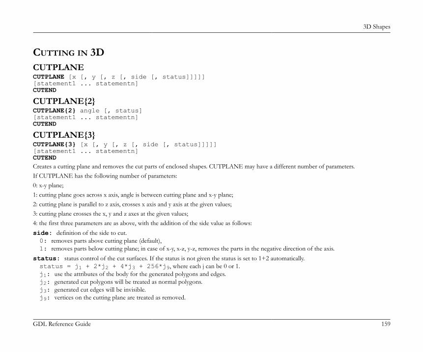
3D Shapes
GDL Reference Guide 159
CUTTING IN 3DCUTPLANECUTPLANE [x [, y [, z [, side [, status]]]]][statement1 ... statementn]CUTEND
CUTPLANE{2}CUTPLANE{2} angle [, status][statement1 ... statementn]CUTEND
CUTPLANE{3}CUTPLANE{3} [x [, y [, z [, side [, status]]]]][statement1 ... statementn]CUTENDCreates a cutting plane and removes the cut parts of enclosed shapes. CUTPLANE may have a different number of parameters.If CUTPLANE has the following number of parameters:0: x-y plane;1: cutting plane goes across x axis, angle is between cutting plane and x-y plane;2: cutting plane is parallel to z axis, crosses x axis and y axis at the given values;3: cutting plane crosses the x, y and z axes at the given values;4: the first three parameters are as above, with the addition of the side value as follows:side: definition of the side to cut.0: removes parts above cutting plane (default),1: removes parts below cutting plane; in case of x-y, x-z, y-z, removes the parts in the negative direction of the axis.
status: status control of the cut surfaces. If the status is not given the status is set to 1+2 automatically.status = j1 + 2*j2 + 4*j3 + 256*j9, where each j can be 0 or 1.j1: use the attributes of the body for the generated polygons and edges.j2: generated cut polygons will be treated as normal polygons.j3: generated cut edges will be invisible.j9: vertices on the cutting plane are treated as removed.

3D Shapes
GDL Reference Guide 160
The cut (without the side parameter) removes parts above the cutting plane. If the first three parameters define the x-y, x-z or y-z plane (forexample, 1.0, 1.0, 0.0 defines the x-y plane), the parts in the positive direction of the third axis are removed.Any number of statements can be added between CUTPLANE and CUTEND. It is also possible to include CUTPLANEs in macros.CUTPLANE parameters refer to the current coordinate system.Transformations between CUTPLANE and CUTEND have no effect on this very cutting plane, but any successive CUTPLANEs willbe transformed. Therefore, it is recommended to use as many transformations to set up the CUTPLANE as necessary, then delete thesetransformations before you define the shapes to cut.If transformations used only to position the CUTPLANE are not removed, you may think that the CUTPLANE is at a wrong position when,in reality, it is the shapes that have moved away.Pairs of CUTPLANE-CUTEND commands can be nested, even within loops. If the final CUTEND is missing, its corresponding CUTPLANEwill be effective on all shapes until the end of the script.
Note 1: If CUTPLANE is not closed with CUTEND, all shapes may be entirely removed. That’s why you always get a warning messageabout missing CUTENDs.
CUTPLANEs in macros affect shapes in the macro only, even if CUTEND is missing.If a macro is called between CUTPLANE and CUTEND, the shapes in the macro will be cut.
Note 2: If you use CUTPLANE{2} with more than two parameters, then this will act like CUTPLANE.
Note 3: Prefer using CUTPLANE{3} instead of CUTPLANE. If you use CUTPLANE with 5 parameters, then the 4th parameter will beomitted. For CUTPLANE{3}, this parameter has effect independently from the 5th parameter.
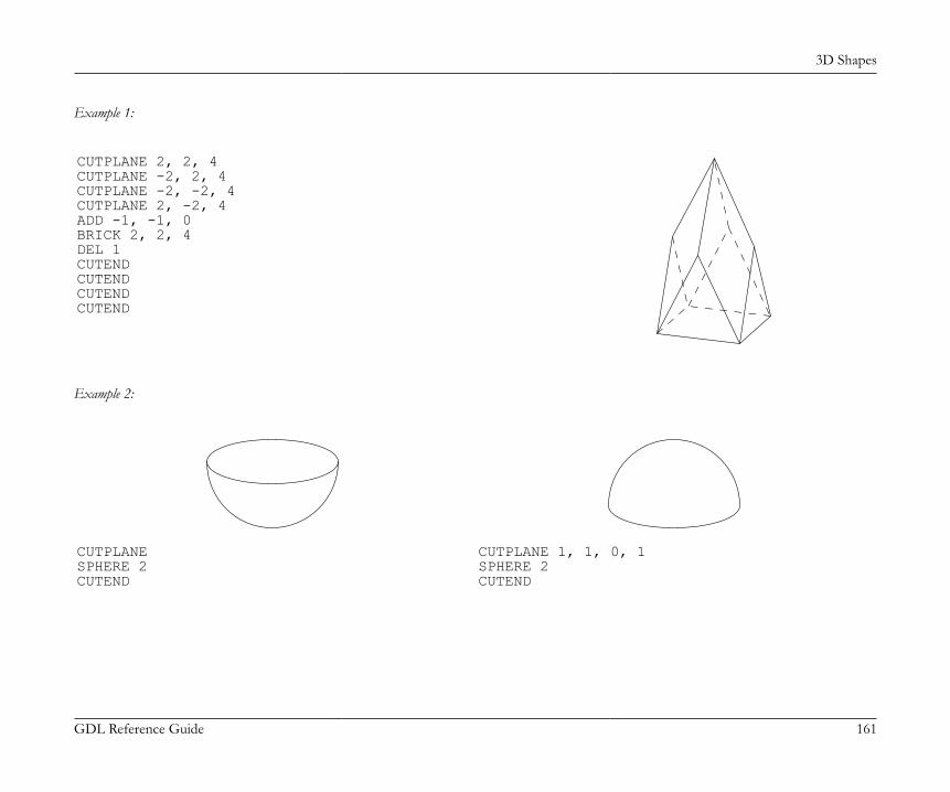
3D Shapes
GDL Reference Guide 161
Example 1:
CUTPLANE 2, 2, 4CUTPLANE -2, 2, 4CUTPLANE -2, -2, 4CUTPLANE 2, -2, 4ADD -1, -1, 0BRICK 2, 2, 4DEL 1CUTENDCUTENDCUTENDCUTEND
Example 2:
CUTPLANESPHERE 2CUTEND
CUTPLANE 1, 1, 0, 1SPHERE 2CUTEND

3D Shapes
GDL Reference Guide 162
Example 3:
CUTPLANE 1.8, 1.8, 1.8SPHERE 2CUTEND
CUTPLANE 1.8, 1.8, 1.8, 1SPHERE 2CUTEND
Example 4:
CUTPLANE 60BRICK 2, 2, 2CUTEND
CUTPLANE -120BRICK 2, 2, 2CUTEND
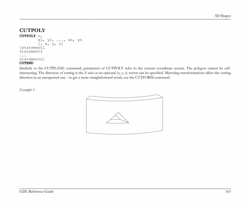
3D Shapes
GDL Reference Guide 163
CUTPOLYCUTPOLY n, x1, y1, ..., xn, yn [, x, y, z][statement1statement2...statementn]CUTENDSimilarly to the CUTPLANE command, parameters of CUTPOLY refer to the current coordinate system. The polygon cannot be self-intersecting. The direction of cutting is the Z axis or an optional (x, y, z) vector can be specified. Mirroring transformations affect the cuttingdirection in an unexpected way - to get a more straightforward result, use the CUTFORM command.
Example 1:
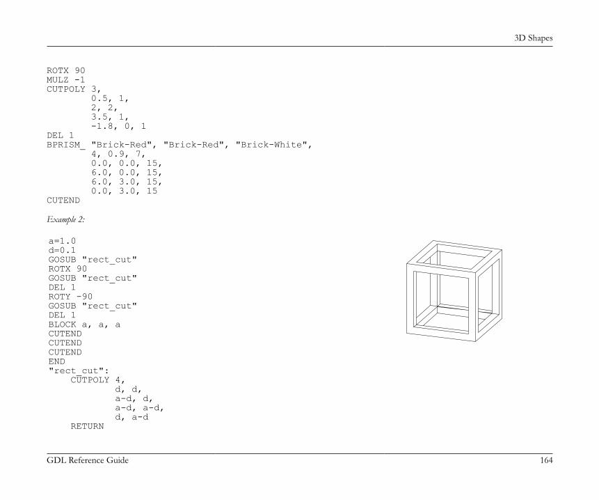
3D Shapes
GDL Reference Guide 164
ROTX 90MULZ -1CUTPOLY 3, 0.5, 1, 2, 2, 3.5, 1, -1.8, 0, 1DEL 1BPRISM_ "Brick-Red", "Brick-Red", "Brick-White", 4, 0.9, 7, 0.0, 0.0, 15, 6.0, 0.0, 15, 6.0, 3.0, 15, 0.0, 3.0, 15CUTEND
Example 2:
a=1.0d=0.1GOSUB "rect_cut"ROTX 90GOSUB "rect_cut"DEL 1ROTY -90GOSUB "rect_cut"DEL 1BLOCK a, a, aCUTENDCUTENDCUTENDEND"rect_cut": CUTPOLY 4, d, d, a-d, d, a-d, a-d, d, a-d RETURN
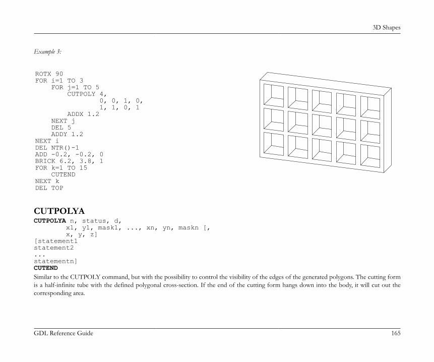
3D Shapes
GDL Reference Guide 165
Example 3:
ROTX 90FOR i=1 TO 3 FOR j=1 TO 5 CUTPOLY 4, 0, 0, 1, 0, 1, 1, 0, 1 ADDX 1.2 NEXT j DEL 5 ADDY 1.2NEXT iDEL NTR()-1ADD -0.2, -0.2, 0BRICK 6.2, 3.8, 1FOR k=1 TO 15 CUTENDNEXT kDEL TOP
CUTPOLYACUTPOLYA n, status, d, x1, y1, mask1, ..., xn, yn, maskn [, x, y, z][statement1statement2...statementn]CUTENDSimilar to the CUTPOLY command, but with the possibility to control the visibility of the edges of the generated polygons. The cutting formis a half-infinite tube with the defined polygonal cross-section. If the end of the cutting form hangs down into the body, it will cut out thecorresponding area.
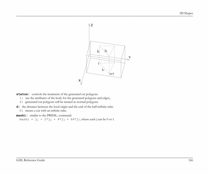
3D Shapes
GDL Reference Guide 166
i
Y
X
Z
jj
ji+1
1
2 3
status: controls the treatment of the generated cut polygons.1: use the attributes of the body for the generated polygons and edges,2: generated cut polygons will be treated as normal polygons.
d: the distance between the local origin and the end of the half-infinite tube.0: means a cut with an infinite tube.
maski: similar to the PRISM_ command.maski = j1 + 2*j2 + 4*j3 + 64*j7, where each j can be 0 or 1.
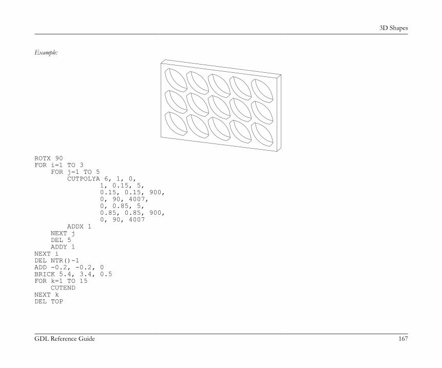
3D Shapes
GDL Reference Guide 167
Example:
ROTX 90FOR i=1 TO 3 FOR j=1 TO 5 CUTPOLYA 6, 1, 0, 1, 0.15, 5, 0.15, 0.15, 900, 0, 90, 4007, 0, 0.85, 5, 0.85, 0.85, 900, 0, 90, 4007 ADDX 1 NEXT j DEL 5 ADDY 1NEXT iDEL NTR()-1ADD -0.2, -0.2, 0BRICK 5.4, 3.4, 0.5FOR k=1 TO 15 CUTENDNEXT kDEL TOP

3D Shapes
GDL Reference Guide 168
CUTSHAPECUTSHAPE d [, status][statement1 statement2 ... statementn]CUTENDCuts a block with "d" thickness, infinite length (both sides of the y axis) and semi-infinite height (above the xy plane).status: controls the treatment of the generated cut polygons. If not specified (for compatibility reasons) the default value is 3.status = j1 + 2*j2, where each j can be 0 or 1.j1: use the attributes of the body for the generated polygons and edges,j2: generated cut polygons will be treated as normal polygons.
Example:
FOR i = 1 TO 5 ADDX 0.4 * i ADDZ 2.5 CUTSHAPE 0.4 DEL 2 ADDX 0.4NEXT iDEL TOPBRICK 4.4, 0.5, 4FOR i = 1 TO 5 CUTENDNEXT i
CUTFORMCUTFORM n, method, status, rx, ry, rz, d, x1, y1, mask1 [, mat1], ... xn, yn, maskn [, matn]Similar to the CUTPOLYA command, but with the possibility to control the form and extent of the cutting body.method: controls the form of the cutting body.1: prism shaped,2: pyramidal,
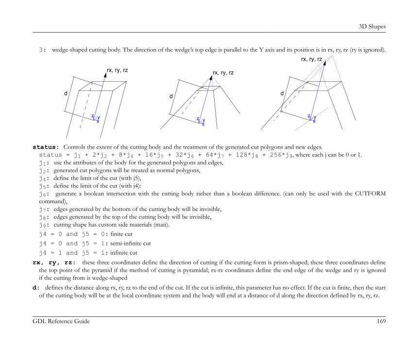
3D Shapes
GDL Reference Guide 169
3: wedge-shaped cutting body. The direction of the wedge’s top edge is parallel to the Y axis and its position is in rx, ry, rz (ry is ignored).
rx, ry, rz
d
z x y
rx, ry, rz
d
z x y
rx, ry, rz
d
z x y
status: Controls the extent of the cutting body and the treatment of the generated cut polygons and new edges.status = j1 + 2*j2 + 8*j4 + 16*j5 + 32*j6 + 64*j7 + 128*j8 + 256*j9, where each j can be 0 or 1.j1: use the attributes of the body for the generated polygons and edges,j2: generated cut polygons will be treated as normal polygons,j4: define the limit of the cut (with j5),j5: define the limit of the cut (with j4):j6: generate a boolean intersection with the cutting body rather than a boolean difference. (can only be used with the CUTFORMcommand),j7: edges generated by the bottom of the cutting body will be invisible,j8: edges generated by the top of the cutting body will be invisible,j9: cutting shape has custom side materials (mati).j4 = 0 and j5 = 0: finite cutj4 = 0 and j5 = 1: semi-infinite cutj4 = 1 and j5 = 1: infinite cut
rx, ry, rz: these three coordinates define the direction of cutting if the cutting form is prism-shaped; these three coordinates definethe top point of the pyramid if the method of cutting is pyramidal; rx-rz coordinates define the end edge of the wedge and ry is ignoredif the cutting from is wedge-shaped
d: defines the distance along rx, ry, rz to the end of the cut. If the cut is infinite, this parameter has no effect. If the cut is finite, then the startof the cutting body will be at the local coordinate system and the body will end at a distance of d along the direction defined by rx, ry, rz.

3D Shapes
GDL Reference Guide 170
If the cut is semi-infinite, then the start of the cutting body will be at a distance of d along the direction defined by rx, ry, rz, and the directionof the semi-infinite cut will be in the opposite direction defined by rx, ry, rz.
mask: defines the visibility of the edges of the cutting body.mask = j1 + 2*j2 + 4*j3 + 8*j4 + 16*j5 + 64*j7, where each j can be 0 or 1.j1: the polygon will create a visible edge upon entry into the body being cut (except when cutting solid body with wedge-shaped cutform,see below),j2: the lengthwise edge of the cutting form will be visible,j3: polygon will create a visible edge upon exiting the body being cut (except when cutting solid body with wedge-shaped cutform, seebelow),j4: the bottom edge of the cutting form will be visible,j5: the top edge of the cutting form will be visible,j7: controls the viewpoint dependent visibility of the lengthwise edge.In case of cutting solid body with wedge-shaped cutform the values for visibility of entry-edges and exit-edges (j1 and j3) are swapped.This behavior is kept for compatibility reasons.
mati: side material of the cutting shape (when status j9 = 1)
CUTFORM{2}CUTFORM{2} n, method, status, rx, ry, rz, d, x1, y1, mask1 [, mat1], ... xn, yn, maskn [, matn]CUTFORM{2} is an extension of the CUTFORM command with the possibility of using inline material definition, that means materials definedin GDL script locally also can be used next to materials defined in global material definitions.
SOLID GEOMETRY COMMANDSGDL is capable of performing specialized 3D operations between solids represented by groups. These operations can be one of the following:
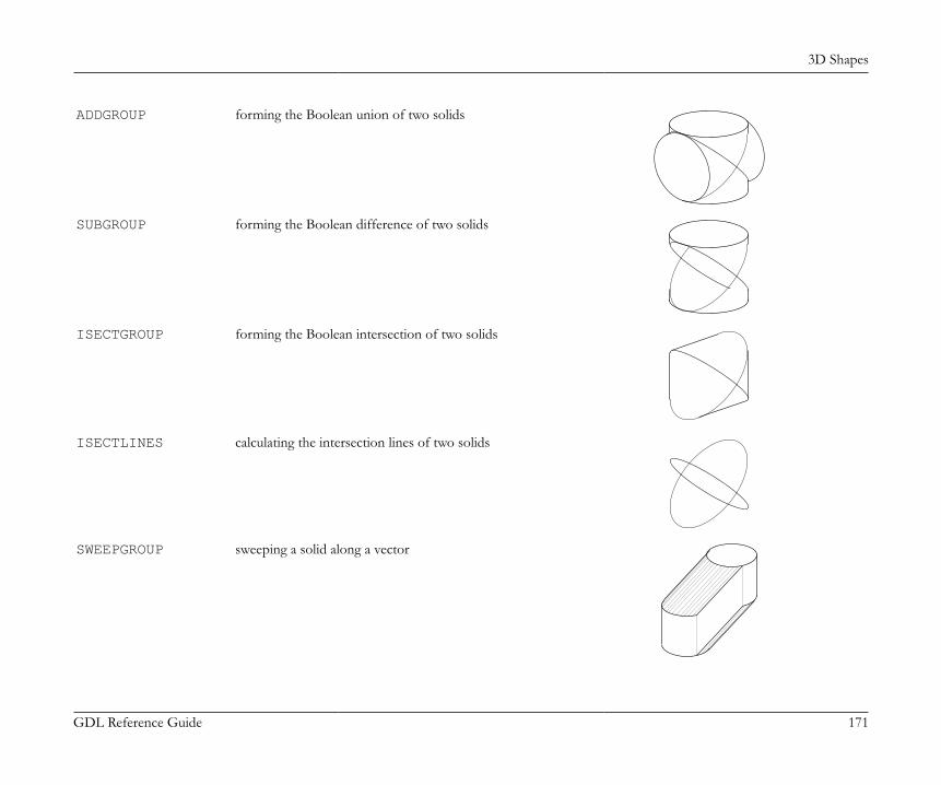
3D Shapes
GDL Reference Guide 171
ADDGROUP forming the Boolean union of two solids
SUBGROUP forming the Boolean difference of two solids
ISECTGROUP forming the Boolean intersection of two solids
ISECTLINES calculating the intersection lines of two solids
SWEEPGROUP sweeping a solid along a vector
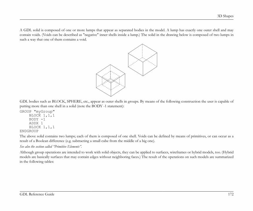
3D Shapes
GDL Reference Guide 172
A GDL solid is composed of one or more lumps that appear as separated bodies in the model. A lump has exactly one outer shell and maycontain voids. (Voids can be described as "negative" inner shells inside a lump.) The solid in the drawing below is composed of two lumps insuch a way that one of them contains a void.
GDL bodies such as BLOCK, SPHERE, etc., appear as outer shells in groups. By means of the following construction the user is capable ofputting more than one shell in a solid (note the BODY -1 statement):GROUP "myGroup" BLOCK 1,1,1 BODY -1 ADDX 1 BLOCK 1,1,1ENDGROUPThe above solid contains two lumps; each of them is composed of one shell. Voids can be defined by means of primitives, or can occur as aresult of a Boolean difference (e.g. subtracting a small cube from the middle of a big one).See also the section called “Primitive Elements”.Although group operations are intended to work with solid objects, they can be applied to surfaces, wireframes or hybrid models, too. (Hybridmodels are basically surfaces that may contain edges without neighboring faces.) The result of the operations on such models are summarizedin the following tables:
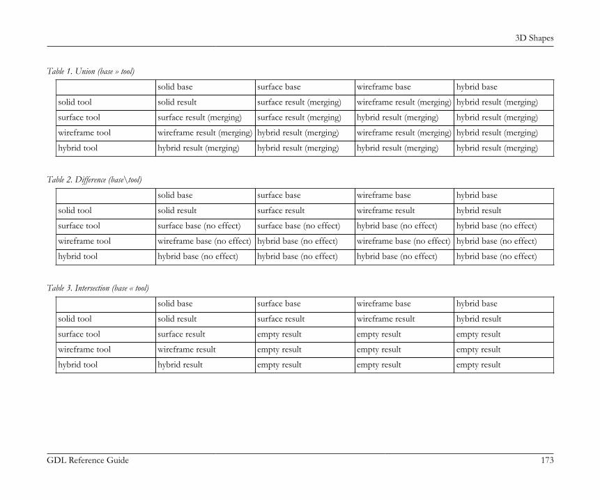
3D Shapes
GDL Reference Guide 173
Table 1. Union (base » tool)
solid base surface base wireframe base hybrid base
solid tool solid result surface result (merging) wireframe result (merging) hybrid result (merging)
surface tool surface result (merging) surface result (merging) hybrid result (merging) hybrid result (merging)
wireframe tool wireframe result (merging) hybrid result (merging) wireframe result (merging) hybrid result (merging)
hybrid tool hybrid result (merging) hybrid result (merging) hybrid result (merging) hybrid result (merging)
Table 2. Difference (base\tool)
solid base surface base wireframe base hybrid base
solid tool solid result surface result wireframe result hybrid result
surface tool surface base (no effect) surface base (no effect) hybrid base (no effect) hybrid base (no effect)
wireframe tool wireframe base (no effect) hybrid base (no effect) wireframe base (no effect) hybrid base (no effect)
hybrid tool hybrid base (no effect) hybrid base (no effect) hybrid base (no effect) hybrid base (no effect)
Table 3. Intersection (base « tool)
solid base surface base wireframe base hybrid base
solid tool solid result surface result wireframe result hybrid result
surface tool surface result empty result empty result empty result
wireframe tool wireframe result empty result empty result empty result
hybrid tool hybrid result empty result empty result empty result
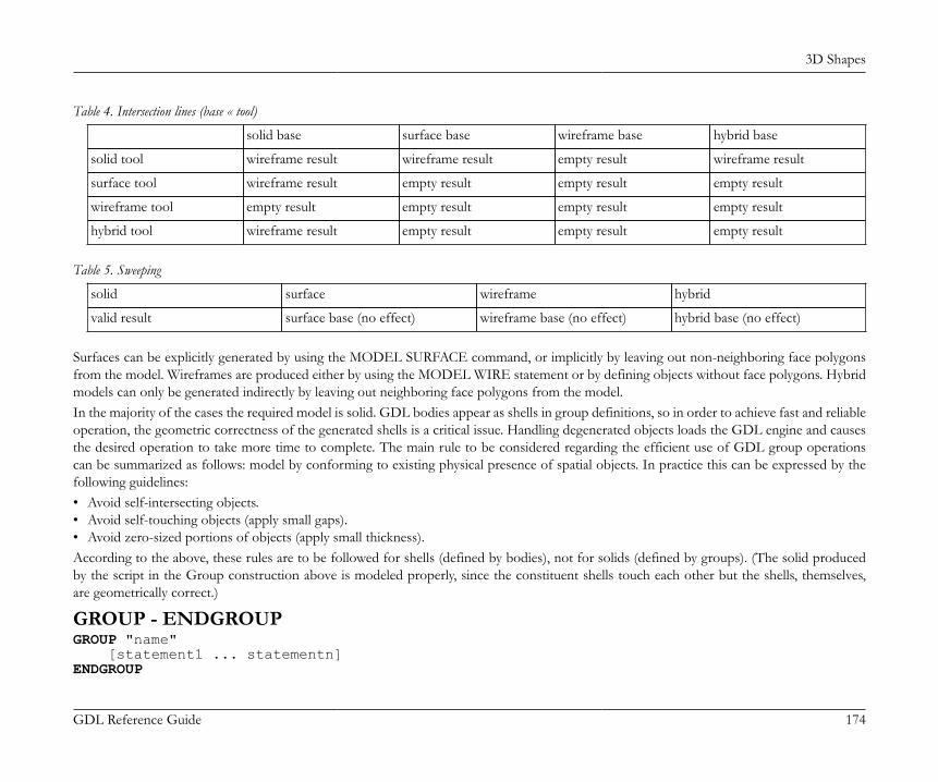
3D Shapes
GDL Reference Guide 174
Table 4. Intersection lines (base « tool)
solid base surface base wireframe base hybrid base
solid tool wireframe result wireframe result empty result wireframe result
surface tool wireframe result empty result empty result empty result
wireframe tool empty result empty result empty result empty result
hybrid tool wireframe result empty result empty result empty result
Table 5. Sweeping
solid surface wireframe hybrid
valid result surface base (no effect) wireframe base (no effect) hybrid base (no effect)
Surfaces can be explicitly generated by using the MODEL SURFACE command, or implicitly by leaving out non-neighboring face polygonsfrom the model. Wireframes are produced either by using the MODEL WIRE statement or by defining objects without face polygons. Hybridmodels can only be generated indirectly by leaving out neighboring face polygons from the model.In the majority of the cases the required model is solid. GDL bodies appear as shells in group definitions, so in order to achieve fast and reliableoperation, the geometric correctness of the generated shells is a critical issue. Handling degenerated objects loads the GDL engine and causesthe desired operation to take more time to complete. The main rule to be considered regarding the efficient use of GDL group operationscan be summarized as follows: model by conforming to existing physical presence of spatial objects. In practice this can be expressed by thefollowing guidelines:• Avoid self-intersecting objects.• Avoid self-touching objects (apply small gaps).• Avoid zero-sized portions of objects (apply small thickness).According to the above, these rules are to be followed for shells (defined by bodies), not for solids (defined by groups). (The solid producedby the script in the Group construction above is modeled properly, since the constituent shells touch each other but the shells, themselves,are geometrically correct.)
GROUP - ENDGROUPGROUP "name" [statement1 ... statementn]ENDGROUP

3D Shapes
GDL Reference Guide 175
Group definition. All bodies between the corresponding GROUP - ENDGROUP statements will be part of the "name" group. Groups are notactually generated (placed), they can be used in group operations or placed explicitly using the PLACEGROUP command. Group definitionscannot be nested, but macro calls containing group definitions and PLACEGROUP commands using other groups can be included.Group names must be unique inside the current script. Transformations, cutplanes outside the group definition have no effect on the groupparts; transformations, cutplanes used inside have no effect on the bodies outside the definition. Group definitions are transparent to attributeDEFINEs and SETs (pens, materials, fills); attributes defined/set before the definition and those defined/set inside the definition are alleffective.
ADDGROUPADDGROUP (g_expr1, g_expr2)ADDGROUP{2} (g_expr1, g_expr2, edgeColor, materialId, materialColor [, operationStatus])ADDGROUP{3} (g_expr1, g_expr2, edgeColor, materialId, materialColor [, operationStatus])
SUBGROUPSUBGROUP (g_expr1, g_expr2)SUBGROUP{2} (g_expr1, g_expr2, edgeColor, materialId, materialColor [, operationStatus])SUBGROUP{3} (g_expr1, g_expr2, edgeColor, materialId, materialColor [, operationStatus])
ISECTGROUPISECTGROUP (g_expr1, g_expr2)ISECTGROUP{2} (g_expr1, g_expr2, edgeColor, materialId, materialColor [, operationStatus])ISECTGROUP{3} (g_expr1, g_expr2, edgeColor, materialId, materialColor [, operationStatus])g_expr1: identifier of the base group.g_expr2: identifier of the tool group.edgeColor: the color of the new edge when it differs from 0.materialId: the material of the new face when it differs from 0.materialColor: the color of the new face when the materialId is 0 and it differs from 0.operationStatus: status control of the operation.operationStatus = j1 + 2*j2, where each j can be 0 or 1.j1: generated new edges will be invisible.j2: cut polygons of the result inherit material and texture projection from the corresponding polygons of the tool group.
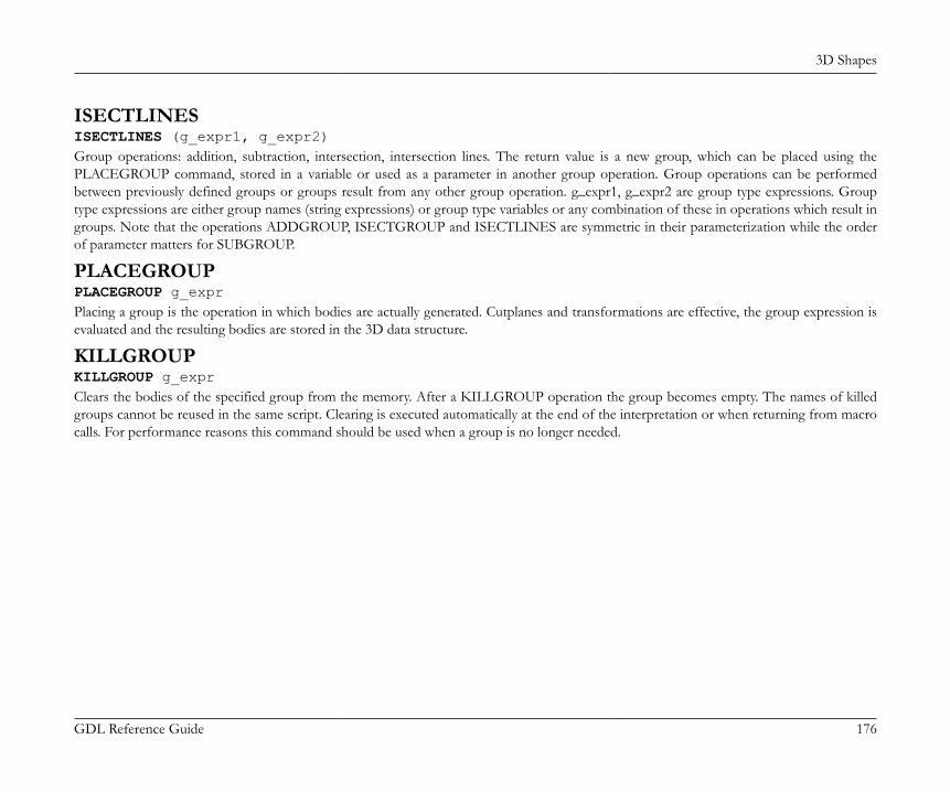
3D Shapes
GDL Reference Guide 176
ISECTLINESISECTLINES (g_expr1, g_expr2)Group operations: addition, subtraction, intersection, intersection lines. The return value is a new group, which can be placed using thePLACEGROUP command, stored in a variable or used as a parameter in another group operation. Group operations can be performedbetween previously defined groups or groups result from any other group operation. g_expr1, g_expr2 are group type expressions. Grouptype expressions are either group names (string expressions) or group type variables or any combination of these in operations which result ingroups. Note that the operations ADDGROUP, ISECTGROUP and ISECTLINES are symmetric in their parameterization while the orderof parameter matters for SUBGROUP.
PLACEGROUPPLACEGROUP g_exprPlacing a group is the operation in which bodies are actually generated. Cutplanes and transformations are effective, the group expression isevaluated and the resulting bodies are stored in the 3D data structure.
KILLGROUPKILLGROUP g_exprClears the bodies of the specified group from the memory. After a KILLGROUP operation the group becomes empty. The names of killedgroups cannot be reused in the same script. Clearing is executed automatically at the end of the interpretation or when returning from macrocalls. For performance reasons this command should be used when a group is no longer needed.
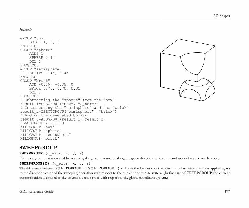
3D Shapes
GDL Reference Guide 177
Example:
GROUP "box" BRICK 1, 1, 1ENDGROUPGROUP "sphere" ADDZ 1 SPHERE 0.45 DEL 1ENDGROUPGROUP "semisphere" ELLIPS 0.45, 0.45ENDGROUPGROUP "brick" ADD -0.35, -0.35, 0 BRICK 0.70, 0.70, 0.35 DEL 1ENDGROUP! Subtracting the "sphere" from the "box"result_1=SUBGROUP("box", "sphere")! Intersecting the "semisphere" and the "brick"result_2=ISECTGROUP("semisphere", "brick")! Adding the generated bodiesresult_3=ADDGROUP(result_1, result_2)PLACEGROUP result_3KILLGROUP "box"KILLGROUP "sphere"KILLGROUP "semisphere"KILLGROUP "brick"
SWEEPGROUPSWEEPGROUP (g_expr, x, y, z)Returns a group that is created by sweeping the group parameter along the given direction. The command works for solid models only.SWEEPGROUP{2} (g_expr, x, y, z)The difference between SWEEPGROUP and SWEEPGROUP{2} is that in the former case the actual transformation matrix is applied againto the direction vector of the sweeping operation with respect to the current coordinate system. (In the case of SWEEPGROUP, the currenttransformation is applied to the direction vector twice with respect to the global coordinate system.)
3D Shapes
GDL Reference Guide 178
SWEEPGROUP{3} (g_expr, x, y, z, edgeColor, materialId, materialColor, method)This version adds a new method selection to SWEEPGROUP{2} and works for surface models also.edgeColor: the color of the new edge when it differs from 0.materialId: the material of the new face when it differs from 0.materialColor: the color of the new face when the materialId is 0 and it differs from 0.method: controls the ending shape of the resulting body.0: same as SWEEPGROUP{2}, both ends come from the originating body,1: the start comes from the originating body, the sweep end is flat
SWEEPGROUP{4} (g_expr, x, y, z, edgeColor, materialId, materialColor, method, status)This version adds a new status parameter to SWEEPGROUP{3}.status: Controls attributes of the result.status = 2*j2, where each j can be 0 or 1.j2: Keep per-polygon texture mapping parameters on the sweeped result (see the PGON command for details).
SWEEPGROUP{5} (g_expr, x, y, z, edgeColor, materialId, materialColor, method, status)SWEEPGROUP{5} is an extension of the SWEEPGROUP{4} command with the possibility of using inline material definition, that meansmaterials defined in GDL script locally also can be used next to materials defined in global material definitions.Compatibility: introduced in ARCHICAD 22.
Example:
GROUP "the_sphere" SPHERE 1ENDGROUPPLACEGROUP SWEEPGROUP{2} ("the_sphere", 2, 0, 0)ADDX 5PLACEGROUP SWEEPGROUP{3} ("the_sphere", 2, 0, 0, 4, 0, 4, 1)del 1

3D Shapes
GDL Reference Guide 179
CREATEGROUPWITHMATERIALCREATEGROUPWITHMATERIAL (g_expr, repl_directive, pen, material)Returns a group that is created by replacing all pens and/or materials in group g_expr.g_expr: group expression identifying the base group.repl_directive:repl_directive = j1 + 2*j2 + 4*j3 + 8*j4, where each j can be 0 or 1.j1: replace pen,j2: replace material,j4: make edges invisible.
pen: replacement pen index.material: replacement material index.
BINARY 3DBINARYBINARY mode [, section, elementID]Special command to include inline binary objects into a GDL macro. A set of vertices, vectors, edges, polygons, bodies and materials is readfrom a special section of the library part file. These are transformed according to the current transformations and merged into the 3D model.The data contained in the binary section is not editable by the user.mode: defines pencolor and material attribute definition usage.0: the current PEN and MATERIAL settings are in effect,1: the current PEN and MATERIAL settings have no effect. The library part will be shown with the stored colors and material definitions.Surface appearance is constant,2: the stored PEN and MATERIAL settings are used, non-defined materials are replaced by current settings,3: the stored PEN and MATERIAL settings are used, non-defined materials are replaced by the stored default attributes.
section: index of the binary part, from 1 to 16.0: you can refer simultaneously to all the existing binary parts,1: Only these sections can be saved from within GDL, BINARY commands without the section argument will also refer to this,2-16: can be used by third party tools.
elementID: ID of an element of this binary part. This parameter is generated during the import process.
3D Shapes
GDL Reference Guide 180
If you open files with a different data structure (e.g., DXF or ZOOM) their 3D description will be converted into binary format.You can save a library part in binary format from the main Library Part editing window through the Save as... command. If the Save in binaryformat checkbox is marked in the Save as... dialog box, the GDL text of the current library part will be replaced with a binary description.Hint: Saving the 3D model after a 3D cutaway operation in binary format will save the truncated model. This way, you can create cut shapes.You can only save your library part in binary format if you have already generated its 3D model.By replacing the GDL description of your library part with a binary description you can considerably reduce the 3D conversion time of theitem. On the other hand, the binary 3D description is not parametric and takes more disk space than an algorithmic GDL script.
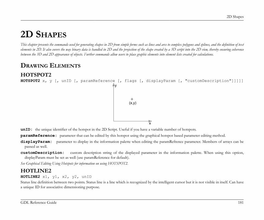
2D Shapes
GDL Reference Guide 181
2D SHAPESThis chapter presents the commands used for generating shapes in 2D from simple forms such as lines and arcs to complex polygons and splines, and the definition of textelements in 2D. It also covers the way binary data is handled in 2D and the projection of the shape created by a 3D script into the 2D view, thereby ensuring coherencebetween the 3D and 2D appearance of objects. Further commands allow users to place graphic elements into element lists created for calculations.
DRAWING ELEMENTS
HOTSPOT2HOTSPOT2 x, y [, unID [, paramReference [, flags [, displayParam [, "customDescription"]]]]]
x
y
(x,y)
unID: the unique identifier of the hotspot in the 2D Script. Useful if you have a variable number of hotspots.paramReference: parameter that can be edited by this hotspot using the graphical hotspot based parameter editing method.displayParam: parameter to display in the information palette when editing the paramRefrence parameter. Members of arrays can be
passed as well.customDescription: custom description string of the displayed parameter in the information palette. When using this option,
displayParam must be set as well (use paramReference for default).See Graphical Editing Using Hotspots for information on using HOTSPOT2.
HOTLINE2HOTLINE2 x1, y1, x2, y2, unIDStatus line definition between two points. Status line is a line which is recognized by the intelligent cursor but it is not visible in itself. Can havea unique ID for associative dimensioning purpose.
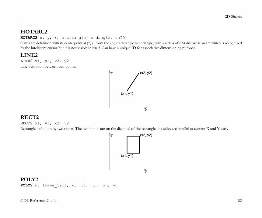
2D Shapes
GDL Reference Guide 182
HOTARC2HOTARC2 x, y, r, startangle, endangle, unIDStatus arc definition with its centerpoint at (x, y) from the angle startangle to endangle, with a radius of r. Status arc is an arc which is recognizedby the intelligent cursor but it is not visible in itself. Can have a unique ID for associative dimensioning purpose.
LINE2LINE2 x1, y1, x2, y2Line definition between two points.
x
y
(x1, y1)
(x2, y2)
RECT2RECT2 x1, y1, x2, y2Rectangle definition by two nodes. The two points are on the diagonal of the rectangle, the sides are parallel to current X and Y axes.
x
y
(x1, y1)
(x2, y2)
POLY2POLY2 n, frame_fill, x1, y1, ..., xn, yn

2D Shapes
GDL Reference Guide 183
An open or closed polygon with n nodes.
x
y
1 2
n
Restriction of parameters:n >= 2
n: number of nodes.x1, y1, ..., xn, yn: coordinates of each nodes.frame_fill:frame_fill = j1 + 2*j2 + 4*j3, where each j can be 0 or 1.j1: draw contourj2: draw fillj3: close an open polygon
POLY2_POLY2_ n, frame_fill, x1, y1, s1, ..., xn, yn, sn
x
y
1 2
n

2D Shapes
GDL Reference Guide 184
Similar to the POLY2 command, but any of the edges can be omitted. If si = 0, the edge starting from the (xi,yi) apex will be omitted.If si = 1, the vertex should be shown. si = -1 is used to define holes directly. You can also define arcs and segments in the polylineusing additional status code values.Restriction of parameters:n >= 2
n: number of nodes.x1, y1, ..., xn, yn: coordinates of each nodes.frame_fill:frame_fill = j1 + 2*j2 + 4*j3 + 8*j4 + 32*j6 + 64*j7, where each j can be 0 or 1.j1: draw contour,j2: draw fill,j3: close an open polygon,j4: local fill orientation,j6: fill is cut fill (default is drafting fill),j7: fill is cover fill (only if j6 = 0, default is drafting fill).
si: Status values:si = j1 + 16*j5 + 32*j6, where each j can be 0 or 1.j1: next segment is visible,j5: next segment is inner line (if 0, generic line),j6: next segment is contour line (effective only if j5 is not set),-1: end of a contour.
Default line property for POLY2_ lines is 0 (generic line), the LINE_PROPERTY command has no effect on POLY2_ edges. Additional statuscodes allow you to create segments and arcs in the planar polyline using special constraints.See the section called “Additional Status Codes” for details.
POLY2_APOLY2_A n, frame_fill, fill_pen, x1, y1, s1, ..., xn, yn, sn
2D Shapes
GDL Reference Guide 185
POLY2_BPOLY2_B n, frame_fill, fill_pen, fill_background_pen, x1, y1, s1, ..., xn, yn, snAdvanced versions of the POLY2_ command, with additional parameters: the fill pen and the fill background pen. All other parameters aresimilar to those described at the POLY2_ command.fill_pen: fill pencolor number.fill_background_pen: fill background pencolor number.Additional status codes allow you to create segments and arcs in the planar polyline using special constraints.See the section called “Additional Status Codes” for details.
POLY2_B{2}POLY2_B{2} n, frame_fill, fill_pen, fill_background_pen, fillOrigoX, fillOrigoY, fillAngle, x1, y1, s1, ..., xn, yn, snAdvanced version of the POLY2_B command where the hatching origin and direction can be defined.frame_fill:frame_fill = j1 + 2*j2 + 4*j3 + 8*j4 + 16*j5 + 32*j6 + 64*j7, where each j can be 0 or 1.j1: draw contourj2: draw fillj3: close an open polygonj4: local fill orientationj5: global fill origin (effective only if j4 is set)j6: fill in cut category (distinctive with j7, drafting category if none is set)j7: fill in cover category (distinctive with j6, drafting category if none is set).
fillOrigoX: X coordinate of the fill origin.fillOrigoY: Y coordinate of the fill origin.fillAngle: direction angle of fill.Additional status codes allow you to create segments and arcs in the planar polyline using special constraints.See the section called “Additional Status Codes” for details.

2D Shapes
GDL Reference Guide 186
POLY2_B{3}POLY2_B{3} n, frame_fill, fill_pen, fill_background_pen, fillOrigoX, fillOrigoY, mxx, mxy, myx, myy, x1, y1, s1, ..., xn, yn, snAdvanced version of the POLY2_B command, where the orientation of the fill can be defined using a matrix.frame_fill:frame_fill = j1 + 2*j2 + 4*j3 + 8*j4 + 16*j5 + 32*j6 + 64*j7 + 128*j8, where each j can be 0 or 1.j1-j7: similar as for previous POLY2_ commands,j8: use sloped fill.
mxx, mxy, myx, myy: if j8 is set, this matrix defines the orientation of the fill.Additional status codes allow you to create segments and arcs in the planar polyline using special constraints.See the section called “Additional Status Codes” for details.
POLY2_B{4}POLY2_B{4} n, frame_fill, fill_pen, fill_background_pen, fillOrigoX, fillOrigoY, mxx, mxy, myx, myy, gradientInnerRadius, x1, y1, s1, ..., xn, yn, snAdvanced version of POLY2_ B{3}, where the inner radius of radial gradient fill can be set.gradientInnerRadius: inner radius of the gradient in case radial gradient fill is selected for the polygon.
POLY2_B{5}POLY2_B{5} n, frame_fill, fillcategory, distortion_flags, fill_pen, fill_background_pen, fillOrigoX, fillOrigoY, mxx, mxy, myx, myy, gradientInnerRadius, x1, y1, s1, ..., xn, yn, snAdvanced version of POLY2_ B{4}, where fill distortion can be controlled in an enhanced way.frame_fill:
2D Shapes
GDL Reference Guide 187
frame_fill = j1 + 2*j2 + 4*j3, where each j can be 0 or 1.j1: draw contourj2: draw fillj3: close an open polygon.
fillcategory:0: Draft,1: Cut,2: Cover.
distortion_flags:distortion_flags = j1 + 2*j2 + 4*j3 + 8*j4 + 16*j5 + 32*j6 + 64*j7, where each j can be 0 or 1.The valid value for distortion_flags is between 0 and 127. Don’t use value out of this range.j1: the fill origin’s X coordinate is the global origin’s X coordinate, meaningful only when j4 is set. The fillOrigo is the origin (0,0) projectedon the line of the (mxx, mxy) vector,j2: the fill origin’s Y coordinate is the global origin’s Y coordinate, meaningful only when j4 is set,j3: create circular distortion using the innerRadius parameter,j4: use local orientation, use the distortion matrix (mij parameters),j5: (effective for symbol fills only) reset the pattern’s X size to the defined X vector’s length (mxx, mxy),j6: (effective for symbol fills only) reset the pattern’s Y size to the defined Y vector’s length (myx, myy),j7: (effective for symbol fills only) keep proportion of symbol fill pattern; effective only if one of j5 and j6 is set.
innerRadius: radius for circular fill distortion; the origin of the base circle will be placed on the Y fill axis in the (0, -innerRadius) position.
POLY2_B{6}POLY2_B{6} n, frame_fill, fillcategory, distortion_flags, fill_pen, fill_background_pen, fillOrigoX, fillOrigoY, mxx, mxy, myx, myy, gradientInnerRadius, x1, y1, s1, pen1, linetype1, ..., xn, yn, sn, penn, linetypenAdvanced version of POLY2_B{5}, where contour attributes (pen and linetype) can be controlled individually for each contour segment.peni: pen index of the contour line starting from control point i.linetypei: line type index of the contour line starting from control point i.Compatibility: introduced in ARCHICAD 21.
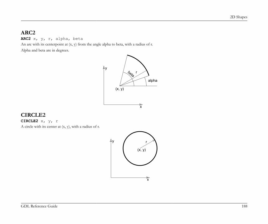
2D Shapes
GDL Reference Guide 188
ARC2ARC2 x, y, r, alpha, betaAn arc with its centerpoint at (x, y) from the angle alpha to beta, with a radius of r.Alpha and beta are in degrees.
x
y
(x, y)
r
alpha
beta
CIRCLE2CIRCLE2 x, y, rA circle with its center at (x, y), with a radius of r.
x
y r
(x, y)
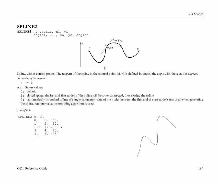
2D Shapes
GDL Reference Guide 189
SPLINE2SPLINE2 n, status, x1, y1, angle1, ..., xn, yn, anglen
x
y
1i
n
anglei
(xi,yi)
Spline, with n control points. The tangent of the spline in the control point (xi, yi) is defined by anglei, the angle with the x axis in degrees.Restriction of parameters:n >= 2
si: Status values:0: default,1: closed spline; the last and first nodes of the spline will become connected, thus closing the spline,2: automatically smoothed spline; the angle parameter value of the nodes between the first and the last node is not used when generatingthe spline. An internal autosmoothing algorithm is used.
Example 1:
SPLINE2 5, 2, 0, 0, 60, 1, 2, 30, 1.5, 1.5, -30, 3, 4, 45, 4, 3, -45
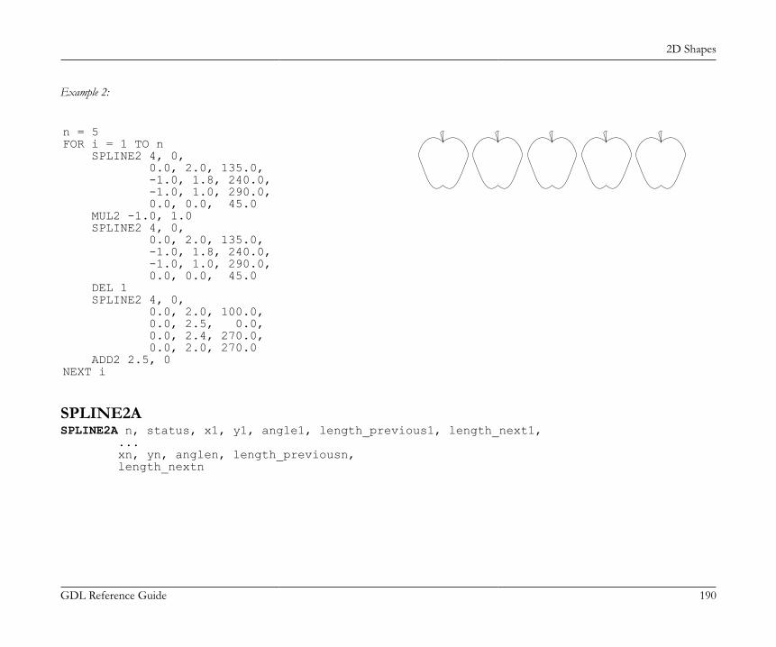
2D Shapes
GDL Reference Guide 190
Example 2:
n = 5FOR i = 1 TO n SPLINE2 4, 0, 0.0, 2.0, 135.0, -1.0, 1.8, 240.0, -1.0, 1.0, 290.0, 0.0, 0.0, 45.0 MUL2 -1.0, 1.0 SPLINE2 4, 0, 0.0, 2.0, 135.0, -1.0, 1.8, 240.0, -1.0, 1.0, 290.0, 0.0, 0.0, 45.0 DEL 1 SPLINE2 4, 0, 0.0, 2.0, 100.0, 0.0, 2.5, 0.0, 0.0, 2.4, 270.0, 0.0, 2.0, 270.0 ADD2 2.5, 0NEXT i
SPLINE2ASPLINE2A n, status, x1, y1, angle1, length_previous1, length_next1, ... xn, yn, anglen, length_previousn, length_nextn
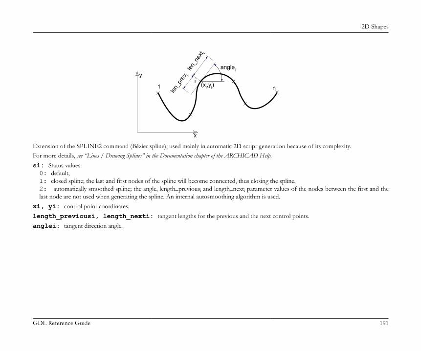
2D Shapes
GDL Reference Guide 191
x
y
1i
n
anglei
(xi,yi)
len_p
rev i
len_n
ext i
Extension of the SPLINE2 command (Bézier spline), used mainly in automatic 2D script generation because of its complexity.For more details, see “Lines / Drawing Splines” in the Documentation chapter of the ARCHICAD Help.si: Status values:0: default,1: closed spline; the last and first nodes of the spline will become connected, thus closing the spline,2: automatically smoothed spline; the angle, length_previousi and length_nexti parameter values of the nodes between the first and thelast node are not used when generating the spline. An internal autosmoothing algorithm is used.
xi, yi: control point coordinates.length_previousi, length_nexti: tangent lengths for the previous and the next control points.anglei: tangent direction angle.

2D Shapes
GDL Reference Guide 192
Example:
SPLINE2A 9, 2, 0.0, 0.0, 0.0, 0.0, 0.0, 0.7, 1.5, 15, 0.9, 1.0, 1.9, 0.8, 72, 0.8, 0.3, 1.9, 1.8, 100, 0.3, 0.4, 1.8, 3.1, 85, 0.4, 0.5, 2.4, 4.1, 352, 0.4, 0.4, 3.5, 3.3, 338, 0.4, 0.4, 4.7, 3.7, 36, 0.4, 0.8, 6.0, 4.6, 0, 0.0, 0.0
PICTURE2PICTURE2 expression, a, b, mask
PICTURE2{2}PICTURE2{2} expression, a, b, maskCan be used in 2D similarly to the PICTURE command in 3D. Unlike in 3D, the mask values have no effect on 2D pictures.A string type expression means a file name, a numerical expression means an index of a picture stored in the library part. A 0 index is a specialvalue, it refers to the preview picture of the library part. For PICTURE2{2} mask = 1 means that exact white colored pixels are transparent.Other pictures can only be stored in library parts when saving the project or selected elements containing pictures as GDL objects.
TEXT ELEMENT
TEXT2TEXT2 x, y, expressionThe value of the calculated numerical or string type expression is written in the set style at the x, y coordinates.See also the [SET] STYLE command and the DEFINE STYLE command.
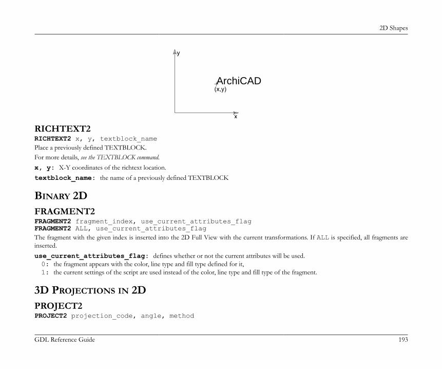
2D Shapes
GDL Reference Guide 193
x
y
(x,y)ArchiCAD
RICHTEXT2RICHTEXT2 x, y, textblock_namePlace a previously defined TEXTBLOCK.For more details, see the TEXTBLOCK command.x, y: X-Y coordinates of the richtext location.textblock_name: the name of a previously defined TEXTBLOCK
BINARY 2DFRAGMENT2FRAGMENT2 fragment_index, use_current_attributes_flagFRAGMENT2 ALL, use_current_attributes_flagThe fragment with the given index is inserted into the 2D Full View with the current transformations. If ALL is specified, all fragments areinserted.use_current_attributes_flag: defines whether or not the current attributes will be used.0: the fragment appears with the color, line type and fill type defined for it,1: the current settings of the script are used instead of the color, line type and fill type of the fragment.
3D PROJECTIONS IN 2DPROJECT2PROJECT2 projection_code, angle, method

2D Shapes
GDL Reference Guide 194
PROJECT2{2}PROJECT2{2} projection_code, angle, method [, backgroundColor, fillOrigoX, fillOrigoY, filldirection]Creates a projection of the 3D script in the same library part and adds the generated lines to the 2D parametric symbol. The 2nd versionPROJECT2{2}, together with a previous [SET] FILL command, allows the user to control the fill background, origin and direction ofthe resulting drawing from the 2D script. The SET FILL 0 shortcut to get an empty fill does not work in this case, you need to referencean actual empty fill.projection_code: the type of projection.3: Top view,4: Side view,5: Side view 2,6: Frontal axonometry,7: Isometric axonometry,8: Monometric axonometry,9: Dimetric axonometry,-3: Bottom view,-6: Frontal bottom view,-7: Isometric bottom view,-8: Monometric bottom view,-9: Dimetric bottom view.
angle: the azimuth angle set in the 3D Projection Settings dialog box.method: the chosen imaging method. If invalid or none is set, the default is hidden lines (2).1: wireframe,2: hidden lines (analytic),3: shading,16: addition modifier: draws vectorial hatches (effective only in hidden line and shaded mode),32: addition modifier: use current attributes instead of attributes from 3D (effective only in shading mode),64: addition modifier: local fill orientation (effective only in shading mode),128: addition modifier: lines are all inner lines (effective only together with 32). Default is generic,256: addition modifier: lines are all contour lines (effective only together with 32, if 128 is not set). Default is generic,512: addition modifier: fills are all cut (effective only together with 32). Default is drafting fills,1024: addition modifier: fills are all cover (effective only together with 32, if 512 is not set). Default is drafting fills.

2D Shapes
GDL Reference Guide 195
BackgroundColor: background color of the fill.fillOrigoX: X coordinate of the fill origin.fillOrigoY: Y coordinate of the fill origin.filldirection: direction angle of fill.
Note: the [SET] FILL command is effective for PROJECT2{2}
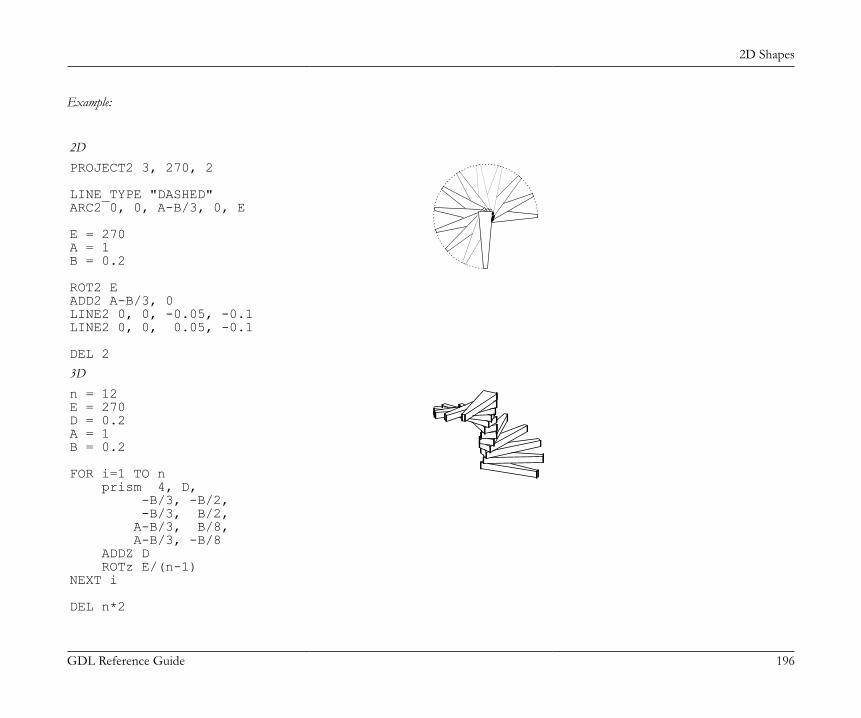
2D Shapes
GDL Reference Guide 196
Example:
2DPROJECT2 3, 270, 2
LINE_TYPE "DASHED"ARC2 0, 0, A-B/3, 0, E
E = 270A = 1B = 0.2
ROT2 EADD2 A-B/3, 0LINE2 0, 0, -0.05, -0.1LINE2 0, 0, 0.05, -0.1
DEL 2
3Dn = 12E = 270D = 0.2A = 1B = 0.2
FOR i=1 TO n prism 4, D, -B/3, -B/2, -B/3, B/2, A-B/3, B/8, A-B/3, -B/8 ADDZ D ROTz E/(n-1)NEXT i
DEL n*2

2D Shapes
GDL Reference Guide 197
PROJECT2{3}PROJECT2{3} projection_code, angle, method, parts [, backgroundColor, fillOrigoX, fillOrigoY, filldirection][[,] PARAMETERS name1=value1, ..., namen=valuen]Creates a projection of the 3D script in the same library part and adds the generated lines to the 2D parametric symbol. The third version,PROJECT2{3}, adds the possibility to define which parts of the projected model are required and to control separately the attributes of thecut and view part, including the line type. You can also generate the projection with actual parameters set in the command.method: the chosen imaging method. If invalid or none is set, the default is hidden lines (2).1: wireframe,2: hidden lines (analytic),3: shading,16: addition modifier: draws vectorial hatches (effective only in hidden line and shaded mode),32: addition modifier: use current attributes instead of attributes from 3D (effective only in shading mode),64: addition modifier: local fill orientation (effective only in shading mode),128: addition modifier: lines are all inner lines (effective only together with 32). Default is generic.256: addition modifier: lines are all contour lines (effective only together with 32, if 128 is not set). Default is generic.512: addition modifier: fills are all cut (effective only together with 32). Default is drafting fills.1024: addition modifier: fills are all cover (effective only together with 32, if 512 is not set). Default is drafting fills.2048: addition modifier: modifiers 16, 32, 64, 128, 256, 512, 1024 and fill attribute parameters are effective only for the view part of theprojection. By default they are effective for all parts.4096: addition modifier: modifiers 16, 32, 64, 128, 256, 512, 1024 and fill attribute parameters are effective only for the cut part of theprojection. By default they are effective for all parts.8192: addition modifier: cut fills are slanted.16384: addition modifier: enables transparency for transparent surfaces. Note that transparency in this case means full transparency forsurfaces with transmittance greater than 50, everything else is non-transparent.
Known limitation: lines of the cut part cannot be treated separately, only all lines together can be set to be inner or contour.Compatibility note: up to ARCHICAD 19, cut polygons were generated with attributes defined by the SECT_FILL command or the SECT_ATTRS commandin the 3D script. From ARCHICAD 20 the attributes of the cut polygons are defined by the cover fill of the outer surfaces (in case the addition modifier 32 is not set).parts: defines the parts to generate. The 1+2+4+8+16+32 value means all parts.parts = j1 + 2*j2 + 4*j3 + 8*j4 + 16*j5 + 32*j6, where each j can be 0 or 1.The j1, j2, j3, j4, j5, j6 numbers represent whether the corresponding parts of the projected model are present (1) or omitted (0):
2D Shapes
GDL Reference Guide 198
j1: cut polygons (effective only in shading mode),j2: cut polygon edges,j3: view polygons,j4: view polygon edges,j5: project 3D hotspots as static 2D hotspots,j6: project 3D hotlines and hotarcs (including related 3D hotspots converted to static 2D hotspots).
PROJECT2{4}PROJECT2{4} projection_code, angle, useTransparency, statusParts, numCutplanes, cutplaneHeight1, ..., cutplaneHeightn,
method1, parts1, cutFillIndex1, cutFillFgPen1, cutFillBgPen1, cutFillOrigoX1, cutFillOrigoY1, cutFillDirection1, cutLinePen1, cutLineType1, projectedFillIndex1, projectedFillFgPen1, projectedFillBgPen1, projectedFillOrigoX1, projectedFillOrigoY1, projectedFillDirection1, projectedLinePen1, projectedLineType1, ... method(numCutplanes+1)), parts(numCutplanes+1), cutFillIndex(numCutplanes+1), cutFillFgPen(numCutplanes+1), cutFillBgPen(numCutplanes+1), cutFillOrigoX(numCutplanes+1), cutFillOrigoY(numCutplanes+1), cutFillDirection(numCutplanes+1), cutLinePen(numCutplanes+1), cutLineType(numCutplanes+1), projectedFillIndex(numCutplanes+1), projectedFillFgPen(numCutplanes+1), projectedFillBgPen(numCutplanes+1), projectedFillOrigoX(numCutplanes+1), projectedFillOrigoY(numCutplanes+1), projectedFillDirection(numCutplanes+1), projectedLinePen(numCutplanes+1), projectedLineType(numCutplanes+1)Compatibility: introduced in ARCHICAD 20.

2D Shapes
GDL Reference Guide 199
Creates a projection of the 3D script in the same library part and adds the generated lines to the 2D parametric symbol. The fourth version,PROJECT2{4}, adds the possibility to define multiple cutting planes parallel to the X-Y plane, and to control the attributes of the cut andprojected parts of the slices, including the line type, pens and fills. The number of cutplanes can be zero, creating exactly one uncut slice(numCutplanes+1).useTransparency: can be 0 (no transparency) or positive integer (1: transparency enabled).statusParts: defines the status parts to generate (hotlines, hotspots, hotarcs). The 1+2 value means all parts. Setting is applied for all slices.statusParts = j1 + 2*j2, where each j can be 0 or 1.The j1, j2 numbers represent whether the corresponding status parts of the projected model are present (1) or omitted (0):j1: project 3D hotspots as static 2D hotspots,j2: project 3D hotlines and hotarcs (including related 3D hotspots converted to static 2D hotspots).
numCutplanes: the number of defined cutplanes. Can be zero, but preferably more.cutplaneHeighti: the position of each individually defined cutplane. Measured as length perpendicularly from the X-Y plane of the
object.method: the chosen imaging method. If invalid or none is set, the default is hidden lines (2).0: the current slice is not part of the projection,1: wireframe,2: hidden lines (analytic),3: shading,4: hidden lines with polygon: the polygon does not eliminate any polygon or line belonging to parts created with shading method, butwill cover/eliminate polygons and lines belonging to other wireframe/hidden line parts. Set it to Air Space for best result. Such explodedpolygons will behave in 2D according to slice order (will cover, but not eliminate shaded parts).16: addition modifier: draws vectorial hatches (effective only in hidden line modes and shaded mode),32: addition modifier: use current attributes instead of attributes from 3D (effective only in shading mode and hidden line with polygonmode),64: addition modifier: local fill orientation (effective only in shading mode and hidden line with polygon mode),128: addition modifier: lines are all inner lines (effective only together with 32). Default is generic.256: addition modifier: lines are all contour lines (effective only together with 32, if 128 is not set). Default is generic.512: addition modifier: fills are all cut (effective only together with 32). Default is drafting fills.1024: addition modifier: fills are all cover (effective only together with 32, if 512 is not set). Default is drafting fills.2048: addition modifier: modifiers 16, 32, 64, 128, 256, 512, 1024 and fill attribute parameters are effective only for the view part of theprojection. By default they are effective for all parts.
2D Shapes
GDL Reference Guide 200
4096: addition modifier: modifiers 16, 32, 64, 128, 256, 512, 1024 and fill attribute parameters are effective only for the cut part of theprojection. By default they are effective for all parts.8192: addition modifier: cut fills are slanted.
partsi: defines the parts to generate. The 1+2+4+8+64 value means all parts.partsi = j1 + 2*j2 + 4*j3 + 8*j4 + 64*j7, where each j can be 0 or 1.The j1, j2, j3, j4, j7 numbers represent whether the corresponding parts of the projected model are present (1) or omitted (0):j1: cut polygons (effective only in shading mode),j2: cut polygon edges,j3: view polygons,j4: view polygon edges,j7: project pointclouds.
cutFillIndexi: fill type index of the cut part of the current slice.cutFillFgPeni: fill pen of the cut part of the current slice.cutFillBgPeni: fill background pen of the cut part of the current slice.cutFillOrigoXi: X coordinate of the cut fill origin of the current slice.cutFillOrigoYi: Y coordinate of the cut fill origin of the current slice.cutFillDirectioni: direction angle of the cut fill of the current slice.cutLinePeni: pen index of cut lines of the current slice.cutLineTypei: line type of cut lines of the current slice.projectedFillIndexi: fill type index of the projected part of the current slice.projectedFillFgPeni: fill pen of the projected part of the current slice.projectedFillBgPeni: fill background pen of the projected part of the current slice.projectedFillOrigoXi: X coordinate of the projected fill origin of the current slice.projectedFillOrigoYi: Y coordinate of the projected fill origin of the current slice.projectedFillDirectioni: direction angle of the projected fill of the current slice.projectedLinePeni: pen index of projected lines of the current slice.projectedLineTypei: line type of projected lines of the current slice.
2D Shapes
GDL Reference Guide 201
DRAWINGS IN THE LISTThese commands only take effect when a list of elements is created.When the library part is a special property type library part and is in some way associated to a library part (Object, Door, Window or Light)placed on the floor plan, including the following commands in its 2D script will refer to the 2D and 3D part of that library part. This is a virtualreference that is resolved during the listing process, using the 2D or 3D script of the currently listed element.
DRAWING2DRAWING2 [expression]Depending on the value of the expression, creates a drawing of the library part (expression = 0, default) or the label of the element (expression= 1) associated with the Property Object containing this command.
DRAWING3DRAWING3 projection_code, angle, method
DRAWING3{2}DRAWING3{2} projection_code, angle, method [, backgroundColor, fillOrigoX, fillOrigoY, filldirection]Similarly to PROJECT2, creates a projection of the 3D script of the library part associated with the property library part containing thiscommand. All parameters are similar to those of PROJECT2 and PROJECT2{2}.method: New method flags in DRAWING3{2}3: shading,32: use current attributes instead of attributes from 3D,64: local fill orientation.
DRAWING3{3}DRAWING3{3} projection_code, angle, method, parts [, backgroundColor, fillOrigoX, fillOrigoY, filldirection][[,] PARAMETERS name1=value1, ..., namen=valuen]Similarly to PROJECT2, creates a projection of the 3D script of the library part associated with the property library part containing thiscommand. All parameters are similar to those of PROJECT2, PROJECT2{2} and PROJECT2{3}.method: New method flags in DRAWING3{3}2048: addition modifier: modifiers 16, 32, 64, 128, 256, 512, 1024 and fill attribute parameters are effective only for the view part of theprojection. By default they are effective for all parts,

2D Shapes
GDL Reference Guide 202
4096: addition modifier: modifiers 16, 32, 64, 128, 256, 512, 1024 and fill attribute parameters are effective only for the cut part of theprojection. By default they are effective for all parts,8192: addition modifier: cut fills are slanted.16384: addition modifier: enables transparency for transparent surfaces. Note that transparency in this case means full transparency forsurfaces with transmittance greater than 50, everything else is non-transparent.

Graphical Editing Using Hotspots
GDL Reference Guide 203
GRAPHICAL EDITING USING HOTSPOTSHotspot-based interactive graphical editing of length and angle type GDL parameters.HOTSPOT x, y, z [, unID [, paramReference [, flags [, displayParam [, "customDescription"]]]]]HOTSPOT2 x, y [, unID [, paramReference [, flags [, displayParam [, "customDescription"]]]]]unID: unique identifier, which must be unique among the hotspots defined in the library part.paramReference: parameter that can be edited by this hotspot using the graphical hotspot based parameter editing method.displayParam: parameter to display in the information palette when editing the paramRefrence parameter. Members of arrays can be
passed as well.customDescription: custom description string for the displayed parameter in the information palette. When using this option,
displayParam must be set as well (use paramReference for default). The value set for the moving type hotspot will be displayed only. It isrecommended to set the same description for all moving hotspots having the same base hotspot.
Examples of valid arguments:D, Arr[5], Arr[2*I+3][D+1], etc.flags: hotspot’s type + hotspot’s attribute:type:1: length type editing, base hotspot,2: length type editing, moving hotspot,3: length type editing, reference hotspot (always hidden),4: angle type editing, base hotspot,5: angle type editing, moving hotspot,6: angle type editing, center of angle (always hidden),7: angle type editing, reference hotspot (always hidden).
attribute: Can be zero or:attribute = 128*j8 + 256*j9 + 512*j10 + 1024*j11, where each j can be 0 or 1.j8: hide hotspot (meaningful for types: 1,2,4,5),j9: editable base hotspot (for types: 1,4),j10: reverse the angle in 2D (for type 6),j11: use paramReference value as meters in paper space.
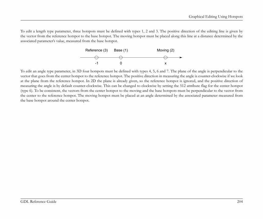
Graphical Editing Using Hotspots
GDL Reference Guide 204
To edit a length type parameter, three hotspots must be defined with types 1, 2 and 3. The positive direction of the editing line is given bythe vector from the reference hotspot to the base hotspot. The moving hotspot must be placed along this line at a distance determined by theassociated parameter’s value, measured from the base hotspot.
Reference (3) Base (1) Moving (2)
-1 0 x
To edit an angle type parameter, in 3D four hotspots must be defined with types 4, 5, 6 and 7. The plane of the angle is perpendicular to thevector that goes from the center hotspot to the reference hotspot. The positive direction in measuring the angle is counter-clockwise if we lookat the plane from the reference hotspot. In 2D the plane is already given, so the reference hotspot is ignored, and the positive direction ofmeasuring the angle is by default counter-clockwise. This can be changed to clockwise by setting the 512 attribute flag for the center hotspot(type 6). To be consistent, the vectors from the center hotspot to the moving and the base hotspots must be perpendicular to the vector fromthe center to the reference hotspot. The moving hotspot must be placed at an angle determined by the associated parameter measured fromthe base hotspot around the center hotspot.

Graphical Editing Using Hotspots
GDL Reference Guide 205
Center (6) Base (4)
Moving (5)
alpha
If several sets of hotspots are defined to edit the same parameter, hotspots are grouped together in the order of the execution of the hotspotcommands. If the editable attribute is set for a base hotspot, the user can also edit the parameter by dragging the base hotspot. Since the basehotspot is supposed to be fixed in the object’s coordinate frame (i.e. its location must be independent of the parameter that is attached to it),the whole object is dragged or rotated along with the base point. (As the parameter’s value is changing, the moving hotspot will not changeits location.)Two length type sets of hotspots can be combined to allow editing of two parameters with only one dragging. If two are combined, the motionof the hotspot is no longer constrained to a line but to the plane determined by the two lines of each set of length editing hotspots. In 3D, thecombination of three sets of length editing hotspots allows the hotspot to be placed anywhere in space. The two lines must not be parallel toeach other, and the three lines must not be on the same plane. A combined parameter editing operation is started if, at the location of the pickedpoint, there are two editable hotspots (moving or editable base) with different associated parameters. If parameters are designed for combinedediting, the base and reference hotspots are not fixed in the object’s coordinate frame, but must move as the other parameter’s value changes.See illustration and example 2.
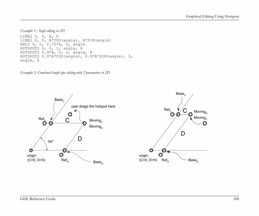
Graphical Editing Using Hotspots
GDL Reference Guide 206
Example 1: Angle editing in 2DLINE2 0, 0, A, 0LINE2 0, 0, A*COS(angle), A*SIN(angle)ARC2 0, 0, 0.75*A, 0, angleHOTSPOT2 0, 0, 1, angle, 6HOTSPOT2 0.9*A, 0, 2, angle, 4HOTSPOT2 0.9*A*COS(angle), 0.9*A*SIN(angle), 3,angle, 5
Example 2: Combined length type editing with 2 parameters in 2D
54o
origin(C=0, D=0) RefD BaseD
MovingD
MovingC
BaseC
RefC
user drags the hotspot here
C
D
origin(C=0, D=0)
MovingD
MovingC
BaseC
RefC C
D
RefD BaseD

Graphical Editing Using Hotspots
GDL Reference Guide 207
! sideX, sideY parametersRECT2 0, 0, A, BRECT2 0, 0, sideX, sideYHOTSPOT2 sideX, 0, 1, sideY, 1HOTSPOT2 sideX, -0.1, 2, sideY, 3HOTSPOT2 sideX, sideY, 3, sideY, 2HOTSPOT2 0, sideY, 4, sideX, 1HOTSPOT2 -0.1, sideY, 5, sideX, 3HOTSPOT2 sideX, sideY, 6, sideX, 2
Example 3: Simple length type editing with 1 parameter
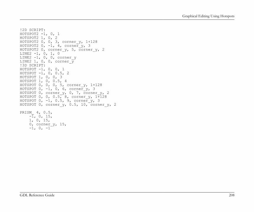
Graphical Editing Using Hotspots
GDL Reference Guide 208
!2D SCRIPT:HOTSPOT2 -1, 0, 1HOTSPOT2 1, 0, 2HOTSPOT2 0, 0, 3, corner_y, 1+128HOTSPOT2 0, -1, 4, corner_y, 3HOTSPOT2 0, corner_y, 5, corner_y, 2LINE2 -1, 0, 1, 0LINE2 -1, 0, 0, corner_yLINE2 1, 0, 0, corner_y!3D SCRIPT:HOTSPOT -1, 0, 0, 1HOTSPOT -1, 0, 0.5, 2HOTSPOT 1, 0, 0, 3HOTSPOT 1, 0, 0.5, 4HOTSPOT 0, 0, 0, 5, corner_y, 1+128HOTSPOT 0, -1, 0, 6, corner_y, 3HOTSPOT 0, corner_y, 0, 7, corner_y, 2HOTSPOT 0, 0, 0.5, 8, corner_y, 1+128HOTSPOT 0, -1, 0.5, 9, corner_y, 3HOTSPOT 0, corner_y, 0.5, 10, corner_y, 2
PRISM_ 4, 0.5, -1, 0, 15, 1, 0, 15, 0, corner_y, 15, -1, 0, -1

Graphical Editing Using Hotspots
GDL Reference Guide 209
Example 4: Combined length type editing with 2 parameters:
!2D SCRIPT:HOTSPOT2 -1, 0, 1HOTSPOT2 1, 0, 2HOTSPOT2 corner_x, 0, 3, corner_y, 1+128HOTSPOT2 corner_x, -1, 4, corner_y, 3HOTSPOT2 corner_x, corner_y, 5, corner_y, 2HOTSPOT2 0, corner_y, 6, corner_x, 1+128HOTSPOT2 -1, corner_y, 7, corner_x, 3HOTSPOT2 corner_x, corner_y, 8, corner_x, 2LINE2 -1, 0, 1, 0LINE2 -1, 0, corner_x, corner_yLINE2 1, 0, corner_x, corner_y
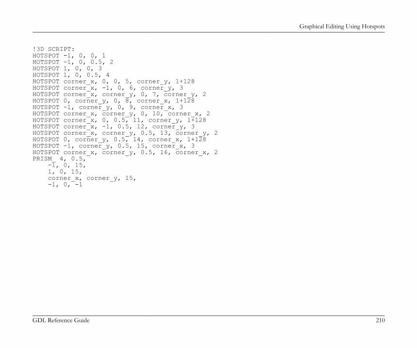
Graphical Editing Using Hotspots
GDL Reference Guide 210
!3D SCRIPT:HOTSPOT -1, 0, 0, 1HOTSPOT -1, 0, 0.5, 2HOTSPOT 1, 0, 0, 3HOTSPOT 1, 0, 0.5, 4HOTSPOT corner_x, 0, 0, 5, corner_y, 1+128HOTSPOT corner_x, -1, 0, 6, corner_y, 3HOTSPOT corner_x, corner_y, 0, 7, corner_y, 2HOTSPOT 0, corner_y, 0, 8, corner_x, 1+128HOTSPOT -1, corner_y, 0, 9, corner_x, 3HOTSPOT corner_x, corner_y, 0, 10, corner_x, 2HOTSPOT corner_x, 0, 0.5, 11, corner_y, 1+128HOTSPOT corner_x, -1, 0.5, 12, corner_y, 3HOTSPOT corner_x, corner_y, 0.5, 13, corner_y, 2HOTSPOT 0, corner_y, 0.5, 14, corner_x, 1+128HOTSPOT -1, corner_y, 0.5, 15, corner_x, 3HOTSPOT corner_x, corner_y, 0.5, 16, corner_x, 2PRISM_ 4, 0.5, -1, 0, 15, 1, 0, 15, corner_x, corner_y, 15, -1, 0, -1

Status Codes
GDL Reference Guide 211
STATUS CODESStatus codes introduced in the following pages allow users to create segments and arcs in planar polylines using special constraints.Planar polylines with status codes at nodes are the basis of many GDL elements: POLY2_, POLY2_A, POLY2_B, POLY2_B{2},POLY2_B{3}, POLY2_B{4}, POLY2_B{5}, POLY_, PLANE_, PRISM_, CPRISM_, BPRISM_, FPRISM_, HPRISM_, SPRISM_,SLAB_, CSLAB_, CROOF_, EXTRUDE, PYRAMID, REVOLVE, SWEEP, TUBE, TUBEAStatus codes allow you:• to control the visibility of planar polyline edges• to define holes in the polyline• to control the visibility of side edges and surfaces• to create segments and arcs in the polyline
STATUS CODE SYNTAXsi: The si number is a binary integer (between 0 and 127) or -1.si = j1 + 2*j2 + 4*j3 + 8*j4 + 64*j7 [+ a_code] , where each j can be 0 or 1.The j1, j2, j3, j4 numbers represent whether the vertices and the sides are present (1) or omitted (0):j1: lower horizontal edge,j2: vertical edge,j3: upper horizontal edge,j4: side face,j7: special additional status value effective only when j2=1 and controls the viewpoint dependent visibility of the current vertical edge,a_code: additional status code (optional), which allows you to create segments and arcs in the polyline,j2=0: the vertical edge is always invisiblej2=1 and j7=1: the vertical edge is only visible when it is a contour observed from the current direction of viewj2=1 and j7=0: the vertical edge is always visiblePossible status values (the heavy lines denote visible edges):
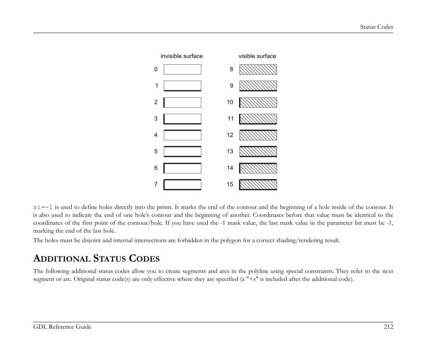
Status Codes
GDL Reference Guide 212
invisible surface visible surface
0
1
2
3
4
5
6
7
8
9
10
11
12
13
14
15
si=-1 is used to define holes directly into the prism. It marks the end of the contour and the beginning of a hole inside of the contour. Itis also used to indicate the end of one hole’s contour and the beginning of another. Coordinates before that value must be identical to thecoordinates of the first point of the contour/hole. If you have used the -1 mask value, the last mask value in the parameter list must be -1,marking the end of the last hole.The holes must be disjoint and internal intersections are forbidden in the polygon for a correct shading/rendering result.
ADDITIONAL STATUS CODESThe following additional status codes allow you to create segments and arcs in the polyline using special constraints. They refer to the nextsegment or arc. Original status code(s) are only effective where they are specified (a "+s" is included after the additional code).
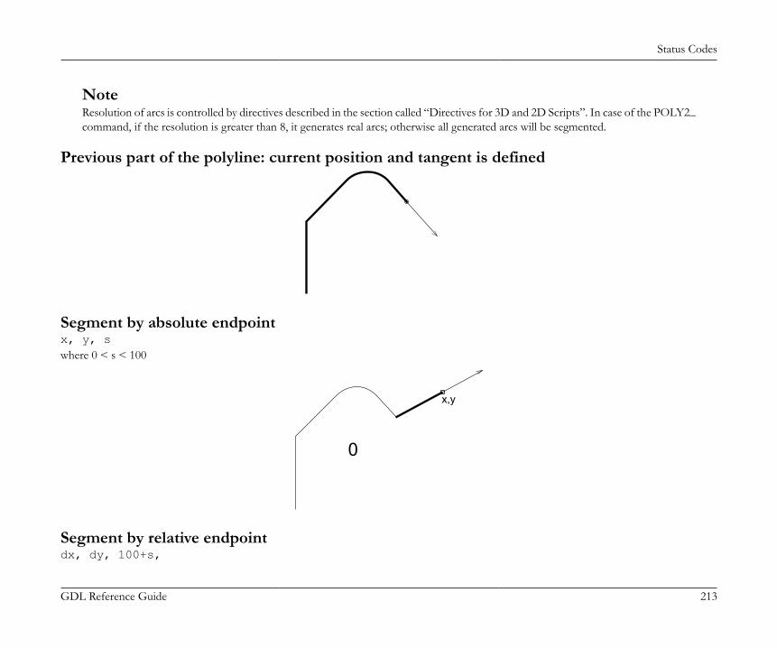
Status Codes
GDL Reference Guide 213
NoteResolution of arcs is controlled by directives described in the section called “Directives for 3D and 2D Scripts”. In case of the POLY2_command, if the resolution is greater than 8, it generates real arcs; otherwise all generated arcs will be segmented.
Previous part of the polyline: current position and tangent is defined
Segment by absolute endpointx, y, swhere 0 < s < 100
0
x,y
Segment by relative endpointdx, dy, 100+s,

Status Codes
GDL Reference Guide 214
where 0 < s < 100
100dx
dy
Segment by length and directionl, a, 200+s,where 0 < s < 100
200
la
Tangential segment by lengthl, 0, 300+s,where 0 < s < 100
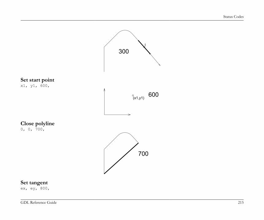
Status Codes
GDL Reference Guide 215
300l
Set start pointx1, y1, 600,
(x1,y1)600
Close polyline0, 0, 700,
700
Set tangentex, ey, 800,

Status Codes
GDL Reference Guide 216
800ex
ey
Set centerpointx0, y0, 900,
900
x0,y0
Tangential arc to endpointx, y, 1000+s,where 0 < s < 100

Status Codes
GDL Reference Guide 217
x,y
1000
Tangential arc by radius and angler, a, 2000+s,where 0 < s < 100
r
a
2000
Arc using centerpoint and point on the final radiusx, y, 3000+s,where 0 < s < 100

Status Codes
GDL Reference Guide 218
3000
x,y
Arc using centerpoint and angle0, a, 4000+s,where 0 < s < 100
4000 a
Full circle using centerpoint and radiusr, 360, 4000+s,where 0 < s < 100

Status Codes
GDL Reference Guide 219
r
4000
In this case the s status refers to the whole circle.All angle values are in degrees. Omitted coordinates marked by 0 (for codes 300, 700, 4000) can have any value.
Example 1:

Status Codes
GDL Reference Guide 220
EXTRUDE 21, 0, 0, 3, 1+2+4+16+32, 0, 0, 0, 7, 0, 0, 7, 3, 1, 6, 3, 1000, ! tangential arc to endpoint 5, 3, 1001, ! tangential arc to endpoint 1, 90, 2000, ! tangential arc by radius and angle 2, 3, 1001, ! tangential arc to endpoint 1, 3, 900, ! set centerpoint 1, 2, 3000, ! arc using startpoint, centerpoint and point on final radius 1, 2.5, 900, ! set centerpoint 0, -180, 4001, ! arc using start point, centerpoint and angle 1, 5, 1000, !tangential arc to endpoint -1, 0, 100, ! segment by (dx, dy) 2, 225, 200, ! segment by (len, angle) -1, 0, 800, ! set tangent -1, 0, 1000, ! tangential arc to endpoint 0, 0, -1, ! end of contour 1, 1, 900, ! set centerpoint 0.5, 360, 4000, ! full circle by centerpoint and radius 3.5, 1.5, 900, ! set centerpoint 1, 360, 4001 ! full circle by centerpoint and radius
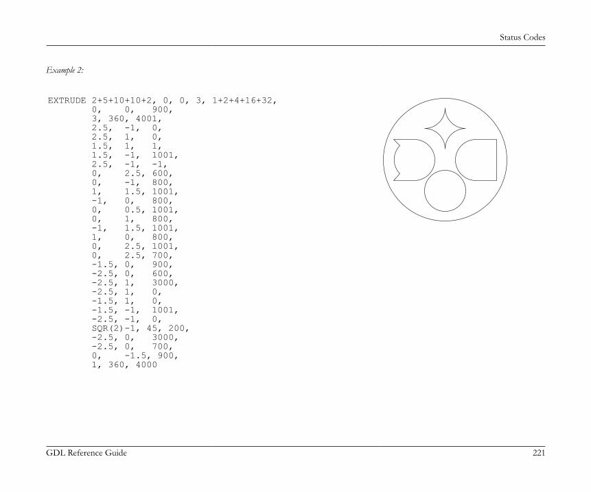
Status Codes
GDL Reference Guide 221
Example 2:
EXTRUDE 2+5+10+10+2, 0, 0, 3, 1+2+4+16+32, 0, 0, 900, 3, 360, 4001, 2.5, -1, 0, 2.5, 1, 0, 1.5, 1, 1, 1.5, -1, 1001, 2.5, -1, -1, 0, 2.5, 600, 0, -1, 800, 1, 1.5, 1001, -1, 0, 800, 0, 0.5, 1001, 0, 1, 800, -1, 1.5, 1001, 1, 0, 800, 0, 2.5, 1001, 0, 2.5, 700, -1.5, 0, 900, -2.5, 0, 600, -2.5, 1, 3000, -2.5, 1, 0, -1.5, 1, 0, -1.5, -1, 1001, -2.5, -1, 0, SQR(2)-1, 45, 200, -2.5, 0, 3000, -2.5, 0, 700, 0, -1.5, 900, 1, 360, 4000

Status Codes
GDL Reference Guide 222
Example 3:
EXTRUDE 3, 1, 1, 3, 1+2+4+16+32, 0, 0, 900, 3, 360, 4001, 2, 360, 4000
Example 4:
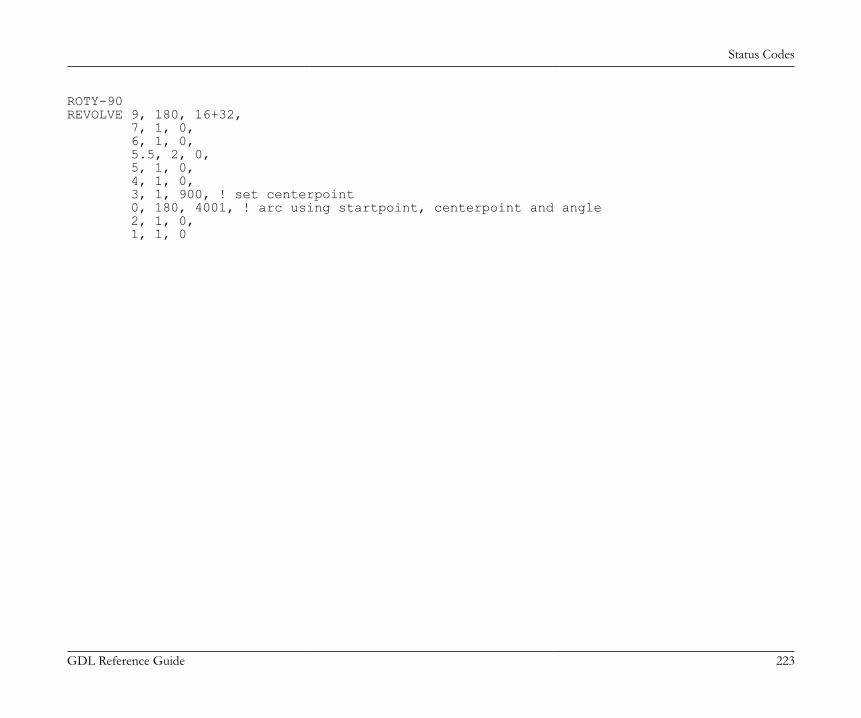
Status Codes
GDL Reference Guide 223
ROTY-90REVOLVE 9, 180, 16+32, 7, 1, 0, 6, 1, 0, 5.5, 2, 0, 5, 1, 0, 4, 1, 0, 3, 1, 900, ! set centerpoint 0, 180, 4001, ! arc using startpoint, centerpoint and angle 2, 1, 0, 1, 1, 0

Attributes
GDL Reference Guide 224
ATTRIBUTESIn the first part of this chapter, directives influencing the interpretation of GDL statements are presented. Directives may define the smoothnessused for cylindrical elements, representation mode in the 3D view or the assignment of an attribute (color, material, text style, etc.) for thesubsequent shapes. Inline attribute definition is covered in the second part. This feature allows you to assign to your objects customized materials,textures, fill patterns, line types and text styles that are not present in the current attribute set of your project.
DIRECTIVESThe influence of directives on the interpretation of the subsequent GDL statements remains in effect until the next directive or the end of thescript. Called scripts inherit the current settings: the changes have local influence. Returning from the script resets the settings as they werebefore the macro call.
Directives for 3D and 2D ScriptsLET[LET] varnam = nValue assignment. The LET directive is optional. The variable will store the evaluated value of n.
RADIUSRADIUS radius_min, radius_maxSets smoothness for cylindrical elements and arcs in polylines.A circle with a radius of r is represented:• if r < radius_min, by a hexagon,• if r >= radius_max, by a 36-edged polygon,• if radius_min < r < radius_max, by a polygon of (6+30*(r-radius_min)/(radius_max-radius_min)) edges.Arc conversion is proportional to this.After a RADIUS statement, all previous RESOL and TOLER statements lose their effect.Restriction of parameters:r_min <= r_max
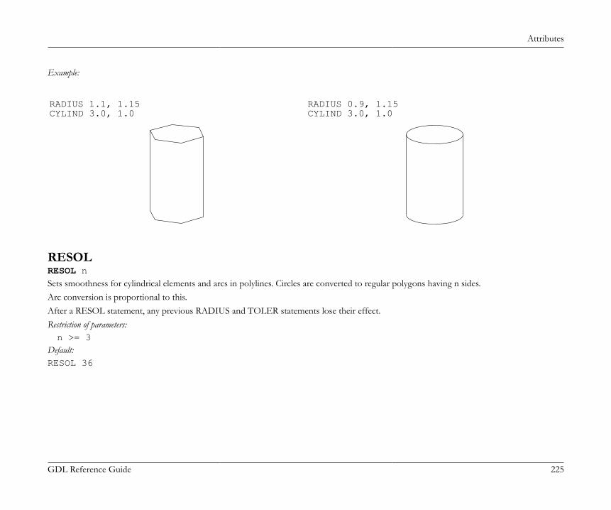
Attributes
GDL Reference Guide 225
Example:
RADIUS 1.1, 1.15CYLIND 3.0, 1.0
RADIUS 0.9, 1.15CYLIND 3.0, 1.0
RESOLRESOL nSets smoothness for cylindrical elements and arcs in polylines. Circles are converted to regular polygons having n sides.Arc conversion is proportional to this.After a RESOL statement, any previous RADIUS and TOLER statements lose their effect.Restriction of parameters:n >= 3
Default:RESOL 36

Attributes
GDL Reference Guide 226
Example:
RESOL 5CYLIND 3.0, 1.0
RESOL 36CYLIND 3.0, 1.0
TOLERTOLER dSets smoothness for cylindrical elements and arcs in polylines. The error of the arc approximation (i.e., the greatest distance between thetheoretical arc and the generated chord) will be smaller than d.After a TOLER statement, any previous RADIUS and RESOL statements lose their effect.

Attributes
GDL Reference Guide 227
Example:
TOLER 0.1CYLIND 3.0, 1.0
TOLER 0.01CYLIND 3.0, 1.0
NoteThe RADIUS, RESOL and TOLER directives set smoothness for cylindrical 3D elements (CIRCLE, ARC, CYLIND, SPHERE,ELLIPS, CONE, ARMC, ARME, ELBOW, REVOLVE) and arcs in 2D polylines using curved edges.
See the section called “Additional Status Codes”.
PENPEN nSets the color.Restriction of parameters:0 < n <= 255
Default:PEN 1if there is no PEN statement in the script.(For library parts, default values come from the library part’s settings. If the script refers to a non-existing index, PEN 1 becomes the defaultsetting.)
Attributes
GDL Reference Guide 228
LINE_PROPERTYLINE_PROPERTY exprDefines the property for all subsequently generated lines in the 2D script (RECT2, LINE2, ARC2, CIRCLE2, SPLINE2, SPLINE2A,POLY2, FRAGMENT2 commands) until the next LINE_PROPERTY statement. Default value is generic.expr: possible values:0: all lines are generic lines,1: all lines are inner,2: all lines are contour.
[SET] STYLE[SET] STYLE name_string[SET] STYLE indexAll the texts generated afterwards will use that style until the next SET STYLE statement.The index is a constant referring to a style stack in the internal data structure (negative indices mean indices in the data structure of inlinematerials (previously defined in the GDL script)). This stack is modified during GDL analysis and can also be modified from within the program.The use of the index instead of the style name is only recommended with the prior use of the IND function.Default:SET STYLE 0(application font, size 5 mm, anchor = 1, normal face) if there is no SET STYLE statement in the script.
Directives Used in 3D Scripts OnlyMODELMODEL WIREMODEL SURFACEMODEL SOLIDSets the representation mode in the current script.MODEL WIRE: only wireframe, no surfaces or volumes. Objects are transparent.MODEL SURFACE, MODEL SOLID: The generation of the section surfaces is based on the relation of the boundary surfaces, so that bothmethods generate the same 3D internal data structure. Objects are opaque.The only distinction can be seen after cutting away a part of the body:MODEL SURFACE: the inside of bodies will be visible,
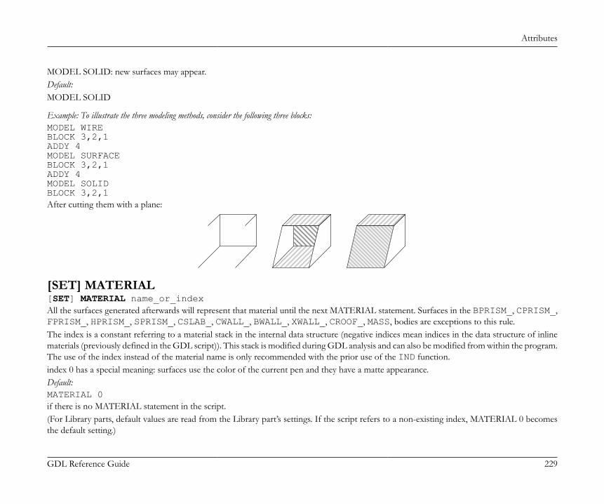
Attributes
GDL Reference Guide 229
MODEL SOLID: new surfaces may appear.Default:MODEL SOLID
Example: To illustrate the three modeling methods, consider the following three blocks:MODEL WIREBLOCK 3,2,1ADDY 4MODEL SURFACEBLOCK 3,2,1ADDY 4MODEL SOLIDBLOCK 3,2,1After cutting them with a plane:
[SET] MATERIAL[SET] MATERIAL name_or_indexAll the surfaces generated afterwards will represent that material until the next MATERIAL statement. Surfaces in the BPRISM_, CPRISM_,FPRISM_, HPRISM_, SPRISM_, CSLAB_, CWALL_, BWALL_, XWALL_, CROOF_, MASS, bodies are exceptions to this rule.The index is a constant referring to a material stack in the internal data structure (negative indices mean indices in the data structure of inlinematerials (previously defined in the GDL script)). This stack is modified during GDL analysis and can also be modified from within the program.The use of the index instead of the material name is only recommended with the prior use of the IND function.index 0 has a special meaning: surfaces use the color of the current pen and they have a matte appearance.Default:MATERIAL 0if there is no MATERIAL statement in the script.(For Library parts, default values are read from the Library part’s settings. If the script refers to a non-existing index, MATERIAL 0 becomesthe default setting.)
Attributes
GDL Reference Guide 230
[SET] BUILDING_MATERIAL[SET] BUILDING_MATERIAL name_or_index [, cut_fill_pen [, cut_fill_bkgd_pen, [iOverrideFlag]]]Compatibility: introduced in ARCHICAD 21.All the shapes generated afterwards will represent the surface, cut fill type (in Section/Elevation), foreground and background pens of theset building material.cut_fill_pen: custom cut fill foreground pen index to override the index of the active building material attributecut_fill_bkgd_pen: custom cut fill background pen index to override the index of the active building material attributeiOverrideFlag: enable "cut_fill_pen" and/or "cut_fill_bkgd_pen" to take effectiOverrideFlag = j1 + 2*j2: , where each j can be 0 or 1.j1: Override cut fill foreground pen with cut_fill_penj2: Override cut fill background pen with cut_fill_bkgd_penOverride parameters are optional: if the "iOverrideFlag" is not set, or the DEFAULT keyword is used in any of the override pen indexparameters, the building material attributes will take effect.
Example: Overriding the cut fill background penBUILDING_MATERIAL buildingMatIndex, DEFAULT, cut_fill_bkgd_pen
All the surfaces generated afterwards will represent the surface of the building material until the next BUILDING_MATERIAL, MATERIAL,SECT_FILL or SECT_ATTRS statement. Surfaces in the BPRISM_, CPRISM_, FPRISM_, HPRISM_, SPRISM_, CSLAB_, CWALL_,BWALL_, XWALL_, CROOF_, MASS, bodies are exceptions to this rule.In Section/Elevation, the displayed cut fill foreground and background pens will match the same attributes of the building material (orthe override parameters set in the command itself), until the next BUILDING_MATERIAL, MATERIAL, SECT_FILL or SECT_ATTRSstatement.A previous BUILDING_MATERIAL statement has no further control of shapes generated after using SECT_FILL or SECT_ATTRSstatements. Shapes generated after using the following statements keep their BUILDING_MATERIAL settings: the MATERIAL statementoverrides only the surfaces of the generated shape, the SECT_ATTRS{2} statement controls the representation of the contour pen and linetype in section view only, while the rest of the attributes are still controlled the building material itself.The index is a constant referring to a building material stack in the internal data structure. The use of the index instead of the building materialname is only recommended with the prior use of the IND function.index 0 has a special meaning: the generated section eliminates the lines based on the fills.Default:
Attributes
GDL Reference Guide 231
BUILDING_MATERIAL 0if there is no BUILDING_MATERIAL statement in the script.(For Library parts, default values are read from the Library part’s settings. If the script refers to a non-existing index, BUILDING_MATERIAL0 becomes the default setting.)
SECT_FILLSECT_FILL fill, fill_background_pen, fill_pen, contour_penor
SECT_ATTRSSECT_ATTRS fill, fill_background_pen, fill_pen, contour_pen [, line_type]Defines the attributes used for the cut part of the 3D elements in the Section/Elevation window. Compatibility: up to ARCHICAD 19 thePROJECT2{3} command is affected too. Inline fill and line_type attributes (defined in master script or 3d script) are not accepted.fill: fill name or index number.fill_background_pen: fill background pencolor number.fill_pen: fill pencolor number.contour_pen: fill contour pencolor number.line_type: line type of polygon edges.
SECT_ATTRS{2}SECT_ATTRS{2} contour_pen [, line_type]Compatibility: introduced in ARCHICAD 21.Defines the contour pen and line type used for the cut part of the 3D elements in Section/Elevation. Can be combined withBUILDING_MATERIAL statement for handling all of the Section/Elevation attributes. Inline line_type attribute (defined in master scriptor 3d script) is not accepted.contour_pen: fill contour pencolor number.line_type: line type of polygon edges.
SHADOWSHADOW casting [, catching]

Attributes
GDL Reference Guide 232
Controls the shadow casting of the elements in PhotoRendering and in vectorial shadow casting.casting: ON, AUTO or OFFON: all the subsequent elements will cast shadows in all circumstances,OFF: none of the subsequent elements will cast shadows in any circumstance,AUTO: shadow casting will be determined automaticallySetting SHADOW OFF for hidden parts will spare memory space and processing time.Setting SHADOW ON ensures that even tiny details will cast shadows.
catching: ON or OFFThis optional parameter controls the appearance of shadows (from other bodies) on surfaces.
If shadow casting isn't specified, the default will be AUTO.
Example:
SHADOW OFF! horizontal surfacePRISM 4, 0.2, 0, 0, 6, 0, 6, 6, 0, 6
ADDX 0.5ADDY 2.5
BRICK 1, 1, 1ADDX 2SHADOW ONBRICK 1, 1, 2ADDX 2SHADOW OFFBRICK 1, 1, 3
DEL 4
Attributes
GDL Reference Guide 233
Directives Used in 2D Scripts OnlyDRAWINDEXDRAWINDEX numberDefines the drawing order of 2D Script elements. Elements with a smaller drawindex will be drawn first.Restriction of parameters:0 < number <= 50
(In the current version of GDL only the 10, 20, 30, 40 and 50 DRAWINDEX values are valid. Other values will be rounded to these.)If no DRAWINDEX directive is present, the default drawing order is the following:1 Figures2 Fills3 Lines4 Text elements
[SET] FILL[SET] FILL name_string[SET] FILL indexAll the 2D polygons generated afterwards will represent that fill until the next SET FILL statement.The index is a constant referring to a fill stack in the internal data structure. This stack is modified during GDL analysis and can also be modifiedfrom within the program. The use of the index instead of the fill name is only recommended with the prior use of the IND function.Default:SET FILL 0i.e., empty fill, if there is no SET FILL statement in the script.
[SET] LINE_TYPE[SET] LINE_TYPE name_string[SET] LINE_TYPE indexAll the 2D lines generated afterwards will represent that line type (in lines, arcs, polylines) until the next SET LINE_TYPE statement. Theindex is a constant that refers to a line type stack in the internal data structure. This stack is modified during GDL analysis and can also bemodified from the program. The use of the index instead of the line type name is only recommended with the prior use of the IND function.Default:SET LINE_TYPE 1
Attributes
GDL Reference Guide 234
i.e., solid line, if there is no SET LINE_TYPE statement in the script.
INLINE ATTRIBUTE DEFINITIONAttributes in can be created using the material, fill and line type dialog boxes. These floor plan attributes can be referenced from any GDLscript. Attributes can also be defined in GDL scripts. There are two different cases:• Attribute definition in the MASTER_GDL script. The MASTER_GDL script is interpreted when the library that contains it is loaded in the
memory. The MASTER_GDL attributes are merged into the floor plan attributes; attributes with the same names are not replaced. Oncethe MASTER_GDL is loaded, the attributes defined in it can be referenced from any script.
• Attribute definition in library parts. The materials and textures defined this way can be used in the script and its second generation scripts.Fills and line types defined and used in the master or 2D script have the same behavior as if they were defined in the MASTER_GDL script,but only if used by name or index (not through a parameter). Fills and line types defined in the master or 3D script can't be accessed inthe 3D script.
The Check GDL Script command in the script window helps to verify whether the material, fill, line type or style parameters are correct.When a material, fill, line type or style is different in the 3D interpretation of the library part from the intended one, but there is no errormessage, this probably means that one or more of the parameter values are incorrect. The Check GDL Scripts command will help you withdetailed messages to find these parameters.
MaterialsDEFINE MATERIALDEFINE MATERIAL name type, surface_red, surface_green, surface_blue [, ambient_ce, diffuse_ce, specular_ce, transparent_ce, shining, transparency_attenuation [, specular_red, specular_green, specular_blue, emission_red, emission_green, emission_blue, emission_att]] [, fill_index [, fillcolor_index, texture_index]]
Note: This command can contain additional data definition.See the section called “Additional Data” for details.Any GDL script can include material definitions prior to the first reference to that material name. This material can only be used for 3Delements in its own script and its second generation scripts.name: name of the material.
Attributes
GDL Reference Guide 235
type: type of the material. The actual number (n) of parameters that define the material is different, depending on the type. The meaningof the parameters and their limits are explained in the examples’ comments.0: general definition, n=16,1: simple definition, n=9 (extra parameters are constants or calculated from given values),2-7: predefined material types, n=3. The three values are the RGB components of the surface color. Other parameters are constantsor calculated from the color.2: matte,3: metal,4: plastic,5: glass,6: glowing,7: constant,10: general definition with fill parameter, n=17,11: simple definition with fill parameter, n=10,12-17: predefined material types with fill parameter, n=4,20: general definition with fill, color index of fill and index of texture parameters, n=19,21: simple definition with fill, color index of fill and index of texture parameters, n=12,22-27: predefined material types with fill, color index of fill and index of texture parameters, n=6.20-27: Special meanings for types 20-27: If the pen number is zero, vectorial hatches will be generated with the active pen. Zero valuefor a texture or fill index allows you to define materials without a vectorial hatch or texture.
Example 1: Materials with solid colorsDEFINE MATERIAL "water" 0, 0.5284, 0.5989, 0.6167,! surface RGB [0.0..1.0] 1.0, ! ambient coefficient [0.0..1.0] 0.5, ! diffuse coefficient [0.0..1.0] 0.5, ! specular coeff. [0.0..1.0] 0.9, ! transparent coeff. [0.0..1.0] 2.0, ! shining [0.0..100.0] 1, ! transparency atten. [0.0..4.0] 0.5284, 0.5989, 0.6167,! specular RGB [0.0..1.0] 0, 0, 0, ! emission RGB [0.0..1.0] 0.0 ! emission atten. [0.0..65.5]

Attributes
GDL Reference Guide 236
DEFINE MATERIAL "asphalt" 1, 0.1995, 0.2023, 0.2418,! surface RGB [0.0..1.0] 1.0, 1.0, 0.0, 0.0, ! ambient, diffuse, specular, transparent ! coefficients [0.0..1.0] 0, ! shining [0..100] 0 ! transparency attenuation [0..4]DEFINE MATERIAL "matte red" 2, 1.0, 0.0, 0.0 ! surface RGB [0.0..1.0]
Example 2: Material with fillDEFINE MATERIAL "Brick-Red" 10, 0.878294, 0.398199, 0.109468, 0.58, 0.85, 0.0, 0.0, 0, 0.0, 0.878401, 0.513481, 0.412253, 0.0, 0.0, 0.0, 0, IND(FILL, "common brick") ! fill index
Example 3: Material with fill and textureDEFINE MATERIAL "Yellow Brick+*" 20, 1, 1, 0, ! surface RGB [0.0 .. 1.0] 0.58, 0.85, 0, 0, ! ambient, diffuse, specular, transparent ! coefficients [0.0 .. 1.0] 0, ! shining [0.0 .. 100.0] 0, ! transparency attenuation [0.0 .. 4.0] 0.878401, 0.513481, 0.412253, ! specular RGB [0.0 .. 1.0] 0, 0, 0, ! emission RGB [0.0 .. 1.0] 0, ! emission attenuation [0.0 .. 65.5] IND(FILL, "common brick"), 61, IND(TEXTURE, "Brick") ! Fill index, color index, texture index
DEFINE MATERIAL BASED_ONDEFINE MATERIAL name [,] BASED_ON orig_name [,] PARAMETERS name1 = expr1 [, ...] [[,] ADDITIONAL_DATA name1 = expr1 [, ...]]
Attributes
GDL Reference Guide 237
Material definition based on an existing material. Specified parameters of the original material will be overwritten by the new values, otherparameters remain untouched. Using the command without actual parameters results in a material exactly the same as the original, but with adifferent name. Parameter values of a material can be obtained using the REQUEST{2} ("Material_info", ...) function.orig_name: name of the original material (name of an existing, previously defined GDL or floor plan material).namei: material parameter name to be overwritten by a new value. Names corresponding to parameters of material definition:gs_mat_surface_r, gs_mat_surface_g, gs_mat_surface_b: (surface RGB [0.0..1.0])gs_mat_ambient: (ambient coefficient [0.0..1.0])gs_mat_diffuse: (diffuse coefficient [0.0..1.0])gs_mat_specular: (specular coefficient [0.0..1.0])gs_mat_transparent: (transparent coefficient [0.0..1.0])gs_mat_shining: (shininess [0.0..100.0])gs_mat_transp_att: (transparency attenuation [0.0..4.0])gs_mat_specular_r, gs_mat_specular_g, gs_mat_specular_b: (specular color RGB [0.0..1.0])gs_mat_emission_r, gs_mat_emission_g, gs_mat_emission_b: (emission color RGB [0.0..1.0])gs_mat_emission_att: (emission attenuation [0.0..65.5])gs_mat_fill_ind: (fill index)gs_mat_fillcolor_ind: (fill color index)gs_mat_texture_ind: (texture index)
expri: new value to overwrite the specified parameter of the material. Value ranges are the same as at the material definition.
Example:n = REQUEST{2} ("Material_info", "Brick-Face", "gs_mat_emission_rgb", em_r, em_g, em_b)em_r = em_r + (1 - em_r) / 3em_g = em_g + (1 - em_g) / 3em_b = em_b + (1 - em_b) / 3DEFINE MATERIAL "Brick-Face light" [,] BASED_ON "Brick-Face" \ PARAMETERS gs_mat_emission_r = em_r, gs_mat_emission_g = em_g, gs_mat_emission_b = em_bSET MATERIAL "Brick-Face"BRICK a, b, zzyzxADDX aSET MATERIAL "Brick-Face light"BRICK a, b, zzyzx
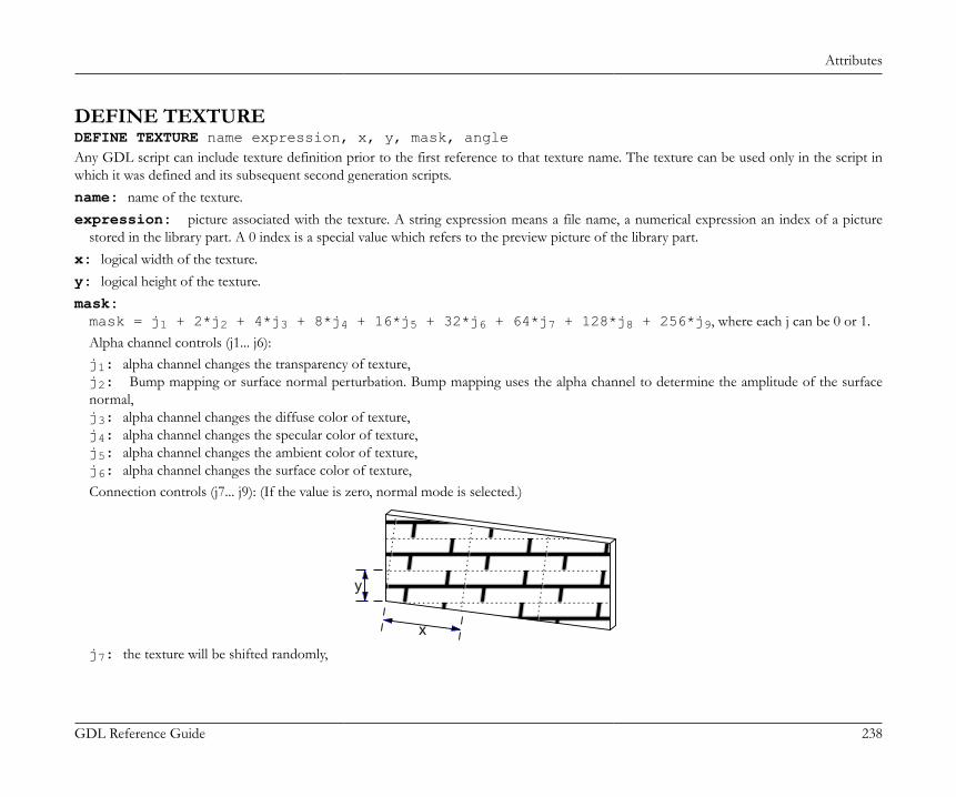
Attributes
GDL Reference Guide 238
DEFINE TEXTUREDEFINE TEXTURE name expression, x, y, mask, angleAny GDL script can include texture definition prior to the first reference to that texture name. The texture can be used only in the script inwhich it was defined and its subsequent second generation scripts.name: name of the texture.expression: picture associated with the texture. A string expression means a file name, a numerical expression an index of a picture
stored in the library part. A 0 index is a special value which refers to the preview picture of the library part.x: logical width of the texture.y: logical height of the texture.mask:mask = j1 + 2*j2 + 4*j3 + 8*j4 + 16*j5 + 32*j6 + 64*j7 + 128*j8 + 256*j9, where each j can be 0 or 1.Alpha channel controls (j1... j6):j1: alpha channel changes the transparency of texture,j2: Bump mapping or surface normal perturbation. Bump mapping uses the alpha channel to determine the amplitude of the surfacenormal,j3: alpha channel changes the diffuse color of texture,j4: alpha channel changes the specular color of texture,j5: alpha channel changes the ambient color of texture,j6: alpha channel changes the surface color of texture,Connection controls (j7... j9): (If the value is zero, normal mode is selected.)
x
y
j7: the texture will be shifted randomly,

Attributes
GDL Reference Guide 239
x
y
j8: mirroring in x direction,
x
y
j9: mirroring in y direction.
x
y
angle: angle of the rotation.
Example:DEFINE TEXTURE "Brick" "Brick.PICT", 1.35, 0.3, 256+128, 35.0
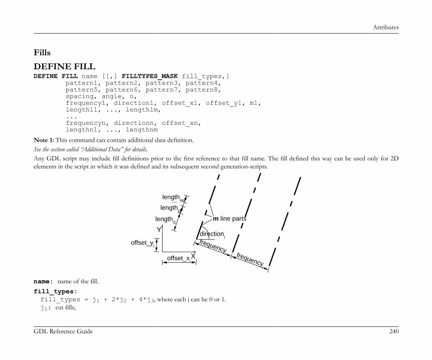
Attributes
GDL Reference Guide 240
FillsDEFINE FILLDEFINE FILL name [[,] FILLTYPES_MASK fill_types,] pattern1, pattern2, pattern3, pattern4, pattern5, pattern6, pattern7, pattern8, spacing, angle, n, frequency1, direction1, offset_x1, offset_y1, m1, length11, ..., length1m, ... frequencyn, directionn, offset_xn, lengthn1, ..., lengthnm
Note 1: This command can contain additional data definition.See the section called “Additional Data” for details.Any GDL script may include fill definitions prior to the first reference to that fill name. The fill defined this way can be used only for 2Delements in the script in which it was defined and its subsequent second generation-scripts.
frequencyi frequency
i
offset_yi
offset_xi
lengthi1
lengthi2
lengthim...
m line parts
directioni
X
Y
name: name of the fill.fill_types:fill_types = j1 + 2*j2 + 4*j3, where each j can be 0 or 1.j1: cut fills,
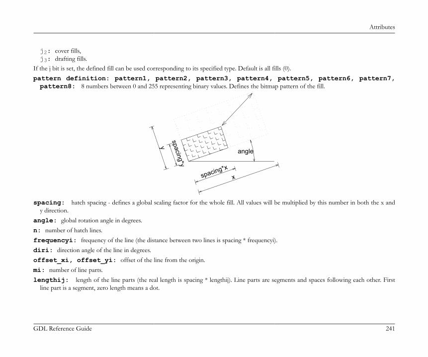
Attributes
GDL Reference Guide 241
j2: cover fills,j3: drafting fills.
If the j bit is set, the defined fill can be used corresponding to its specified type. Default is all fills (0).pattern definition: pattern1, pattern2, pattern3, pattern4, pattern5, pattern6, pattern7,pattern8: 8 numbers between 0 and 255 representing binary values. Defines the bitmap pattern of the fill.
y
x
spacing*y
spacing*x
angle
spacing: hatch spacing - defines a global scaling factor for the whole fill. All values will be multiplied by this number in both the x andy direction.
angle: global rotation angle in degrees.n: number of hatch lines.frequencyi: frequency of the line (the distance between two lines is spacing * frequencyi).diri: direction angle of the line in degrees.offset_xi, offset_yi: offset of the line from the origin.mi: number of line parts.lengthij: length of the line parts (the real length is spacing * lengthij). Line parts are segments and spaces following each other. First
line part is a segment, zero length means a dot.
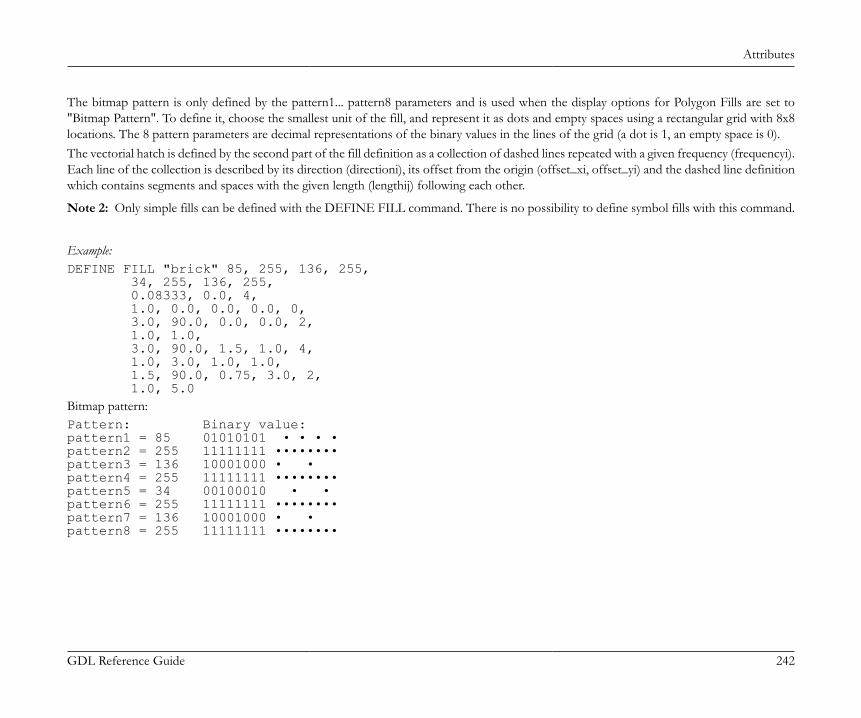
Attributes
GDL Reference Guide 242
The bitmap pattern is only defined by the pattern1... pattern8 parameters and is used when the display options for Polygon Fills are set to"Bitmap Pattern". To define it, choose the smallest unit of the fill, and represent it as dots and empty spaces using a rectangular grid with 8x8locations. The 8 pattern parameters are decimal representations of the binary values in the lines of the grid (a dot is 1, an empty space is 0).The vectorial hatch is defined by the second part of the fill definition as a collection of dashed lines repeated with a given frequency (frequencyi).Each line of the collection is described by its direction (directioni), its offset from the origin (offset_xi, offset_yi) and the dashed line definitionwhich contains segments and spaces with the given length (lengthij) following each other.
Note 2: Only simple fills can be defined with the DEFINE FILL command. There is no possibility to define symbol fills with this command.
Example:DEFINE FILL "brick" 85, 255, 136, 255, 34, 255, 136, 255, 0.08333, 0.0, 4, 1.0, 0.0, 0.0, 0.0, 0, 3.0, 90.0, 0.0, 0.0, 2, 1.0, 1.0, 3.0, 90.0, 1.5, 1.0, 4, 1.0, 3.0, 1.0, 1.0, 1.5, 90.0, 0.75, 3.0, 2, 1.0, 5.0Bitmap pattern:Pattern: Binary value:pattern1 = 85 01010101 • • • •pattern2 = 255 11111111 ••••••••pattern3 = 136 10001000 • •pattern4 = 255 11111111 ••••••••pattern5 = 34 00100010 • •pattern6 = 255 11111111 ••••••••pattern7 = 136 10001000 • •pattern8 = 255 11111111 ••••••••
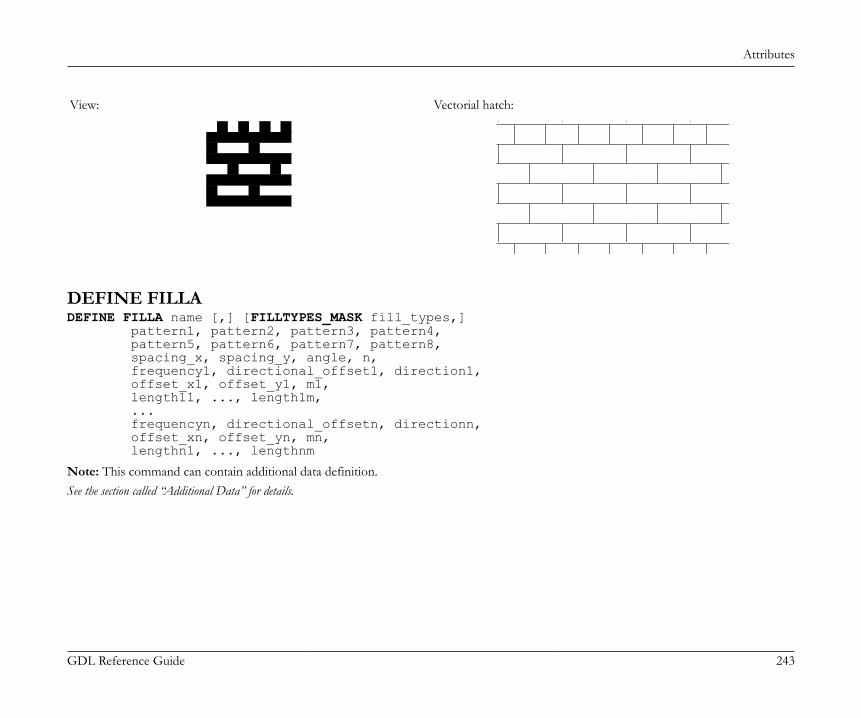
Attributes
GDL Reference Guide 243
View: Vectorial hatch:
DEFINE FILLADEFINE FILLA name [,] [FILLTYPES_MASK fill_types,] pattern1, pattern2, pattern3, pattern4, pattern5, pattern6, pattern7, pattern8, spacing_x, spacing_y, angle, n, frequency1, directional_offset1, direction1, offset_x1, offset_y1, m1, length11, ..., length1m, ... frequencyn, directional_offsetn, directionn, offset_xn, offset_yn, mn, lengthn1, ..., lengthnm
Note: This command can contain additional data definition.See the section called “Additional Data” for details.
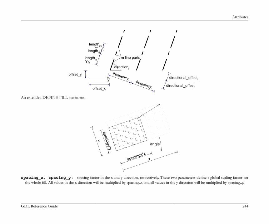
Attributes
GDL Reference Guide 244
X
Y
directional_offseti
directional_offseti
lengthi1
lengthi2
lengthim...
frequencyi frequency
i
offset_yi
offset_xi
directioni
m line parts
An extended DEFINE FILL statement.
xspacingx*x
spacingy*y
y
angle
spacing_x, spacing_y: spacing factor in the x and y direction, respectively. These two parameters define a global scaling factor forthe whole fill. All values in the x direction will be multiplied by spacing_x and all values in the y direction will be multiplied by spacing_y.

Attributes
GDL Reference Guide 245
directional_offseti: the offset of the beginning of the next similar hatch line, measured along the line’s direction. Each line ofthe series will be drawn at a distance defined by frequencyi with an offset defined by directional_offseti. The real length of the offset willbe modulated by the defined spacing.
Example:DEFINE FILLA "TEST" 8, 142, 128, 232, 8, 142, 128, 232, 0.5, 0.5, 0, 2, 2, 1, 90, 0, 0, 2, 1, 1, 1, 2, 0, 0, 0, 2, 1, 3FILL "TEST"POLY2 4, 6, -0.5, -0.5, 12, -0.5, 12, 6, -0.5, 6Bitmap pattern:Pattern: Binary value:pat1 = 8 00001000 •pat2 = 142 10001110 • •••pat3 = 128 10000000 •pat4 = 232 11101000 ••• •pat5 = 8 00001000 •pat6 = 142 10001110 • •••pat7 = 128 10000000 •pat8 = 232 11101000 ••• •
View: Vectorial hatch:
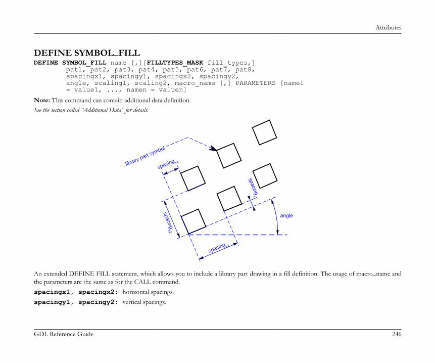
Attributes
GDL Reference Guide 246
DEFINE SYMBOL_FILLDEFINE SYMBOL_FILL name [,][FILLTYPES_MASK fill_types,] pat1, pat2, pat3, pat4, pat5, pat6, pat7, pat8, spacingx1, spacingy1, spacingx2, spacingy2, angle, scaling1, scaling2, macro_name [,] PARAMETERS [name1 = value1, ..., namen = valuen]
Note: This command can contain additional data definition.See the section called “Additional Data” for details.
spacing x2
spacing x1
spacingy2
spacingy1
library part symbol
angle
An extended DEFINE FILL statement, which allows you to include a library part drawing in a fill definition. The usage of macro_name andthe parameters are the same as for the CALL command.spacingx1, spacingx2: horizontal spacings.spacingy1, spacingy2: vertical spacings.
Attributes
GDL Reference Guide 247
scaling1: horizontal scale.scaling2: vertical scale.macro_name: the name of the library part.
DEFINE SOLID_FILLDEFINE SOLID_FILL name [[,] FILLTYPES_MASK fill_types]Defines a solid fill.
Note: This command can contain additional data definition.See the section called “Additional Data” for details.
DEFINE EMPTY_FILLDEFINE EMPTY_FILL name [[,] FILLTYPES_MASK fill_types]Defines an empty fill.
Note: This command can contain additional data definition.See the section called “Additional Data” for details.
DEFINE LINEAR_GRADIENT_FILLDEFINE LINEAR_GRADIENT_FILL name [[,] FILLTYPES_MASK fill_types]Define linear gradient fill.
DEFINE RADIAL_GRADIENT_FILLDEFINE RADIAL_GRADIENT_FILL name [[,] FILLTYPES_MASK fill_types]Define radial gradient fill.
DEFINE TRANSLUCENT_FILLDEFINE TRANSLUCENT_FILL name [[,] FILLTYPES_MASK fill_types] pat1, pat2, pat3, pat4, pat5, pat6, pat7, pat8, percentageDefine a fill, which shows the background and foreground colors in mixture defined by the given percentage value.percentage: percentage of foreground color opacity; 0 displays background color only (like empty fill), 100 displays the foreground
color only (like solid fill).

Attributes
GDL Reference Guide 248
DEFINE IMAGE_FILLDEFINE IMAGE_FILL name image_name [[,] FILLTYPES_MASK fill_types] part1, part2, part3, part4, part5, part6, part7, part8, image_vert_size, image_hor_size, image_mask, image_rotangleDefine a fill based on an image pattern.image_name: name of the pattern image loaded in the current library.image_vert_size, image_hor_size: model size of the pattern.image_mask: tiling directiveimage_mask = 1024*j11 + 2048*j12, where each j can be 0 or 1.For more information about laying out images on a surface see the DEFINE TEXTURE command.j11: mirroring in x directionj12: mirroring in y direction
image_rotangle: rotation angle of the pattern from the normal coordinate system.
Line TypesDEFINE LINE_TYPEDEFINE LINE_TYPE name spacing, n, length1, ..., lengthn
Note 1: This command can contain additional data definition.See the section called “Additional Data” for details.Any GDL script may include line type definitions prior to the first reference to that line-type name. The line type defined this way can be usedonly for 2D elements in the script in which it was defined and its subsequent second generation scripts.name: name of the line type.spacing: spacing factor.n: number of the line parts.lengthi: length of the line parts (the real length is spacing * lengthi). Line parts consist of segments and spaces. First line part is a segment,
zero length means a dot.
Note 2: Only simple line types - i.e. consisting only of segments and spaces - can be defined with this command, defining symbol line typescan be done with the DEFINE SYMBOL_LINE command.

Attributes
GDL Reference Guide 249
Example:DEFINE LINE_TYPE "line - - ." 1, 6, 0.005, 0.002, 0.001, 0.002, 0.0, 0.002
DEFINE SYMBOL_LINEDEFINE SYMBOL_LINE name dash, gap, macro_name PARAMETERS [name1 = value1, ... namen = valuen]
Note: This command can contain additional data definition.See the section called “Additional Data” for details.An extended DEFINE LINE statement, which allows you to include a library part drawing in a line definition. The usage of macro_name andthe parameters are the same as for the CALL command.dash: scale of both line components.gap: gap between each component.
Text Styles and Text BlocksDEFINE STYLEDEFINE STYLE name font_family, size, anchor, face_codeRecommended to be used with the TEXT2 and TEXT commands.GDL scripts may include style definitions prior to the first reference to that style name. The style defined this way can be used only in the scriptin which it was defined and its subsequent second generation scripts.name: name of the style.font_family: name of the used font family (e.g., Garamond).size: height of the "l" character in millimeters in paper space or meters in model space.If the defined style is used with the TEXT2 and TEXT commands, size means character heights in millimeters.If used with PARAGRAPH strings in the RICHTEXT2 and RICHTEXT commands, size meaning millimeters or meters depends on thefixed_height parameter of the TEXTBLOCK definition, while the outline and shadow face_code values and the anchor values are not effective.anchor: code of the position point in the text.

Attributes
GDL Reference Guide 250
1 2 3
4 5 6
7 8 9
face_code: a combination of the following values:face_code = j1 + 2*j2 + 4*j3, where each j can be 0 or 1.j1: bold,j2: italic,j3: underline,If face_code = 0, then style is normal.
DEFINE STYLE{2}DEFINE STYLE{2} name font_family, size, face_codeNew version of style definition, recommended to be used with PARAGRAPH definitions.name: name of the style.font_family: name of the used font family (e.g., Garamond).size: height of the characters in mm or m in model space.face_code: a combination of the following values:face_code = j1 + 2*j2 + 4*j3 + 32*j6 + 64*j7 + 128*j8, where each j can be 0 or 1.j1: bold,j2: italic,j3: underline,j6: superscript,j7: subscript,j8: strikethrough.If face_code = 0, then style is normal.

Attributes
GDL Reference Guide 251
If the defined style is used with the TEXT2 command, size means character heights in millimeters, while the superscript, subscript andstrikethrough face_code values are not effective. If used with PARAGRAPH strings in the RICHTEXT2 and RICHTEXT commands, sizemeaning millimeters or meters depends on the fixed_height parameter of the TEXTBLOCK definition.
PARAGRAPHPARAGRAPH name alignment, firstline_indent, left_indent, right_indent, line_spacing [, tab_position1, ...] [PEN index] [[SET] STYLE style1] [[SET] MATERIAL index] 'string1' 'string2' ... 'string n' [PEN index] [[SET] STYLE style2] [[SET] MATERIAL index] 'string1' 'string2' ... 'string n' ...ENDPARAGRAPHGDL scripts may include paragraph definitions prior to the first reference to that paragraph name. The paragraph defined this way can be usedonly in the script in which it was defined and its subsequent second generation scripts. A paragraph is defined to be a sequence of an arbitrarynumber of strings (max 256 characters long each) with different attributes: style, pen and material (3D). If no attributes are specified insidethe paragraph definition, actual (or default) attributes are used. The new lines included in a paragraph string (using the special character '\n')will automatically split the string into identical paragraphs, each containing one line. Paragraph definitions can be referenced by name in theTEXTBLOCK command. All length type parameters (firstline_indent, left_indent, right_indent, tab_position) meaning millimeters or metersdepends on the fixed_height parameter of the TEXTBLOCK definition.name: name of the paragraph. Can be either string or integer. Integer identifiers works only with the TEXTBLOCK_ commandalignment: alignment of the paragraph strings. Possible values:1: left aligned,2: center aligned,
Attributes
GDL Reference Guide 252
3: right aligned,4: full justified.
firstline_indent: first line indentation, in mm or m in model space.left_indent: left indentation, in mm or m in model space.right_indent: right indentation, in mm or m in model space.line_spacing: line spacing factor. The default distance between the lines (character size + distance to the next line) defined by the
actual style will be multiplied by this number.tab_positioni: consecutive tabulator positions (each relative to the beginning of the paragraph), in mm or m in model space. Tabulators
in the paragraph strings will snap to these positions. If no tabulator positions are specified, default values are used (12.7 mm). Works onlywith '\t' special character.
stringi: part of the text. Can be either constant string or string type parameter.
TEXTBLOCKTEXTBLOCK name width, anchor, angle, width_factor, charspace_factor, fixed_height, 'string_expr1' [, 'string_expr2', ...]Textblock definition. GDL scripts may include textblock definitions prior to the first reference to that textblock name. The textblock defined thisway can be used only in the script in which it was defined and its subsequent second generation scripts. A textblock is defined to be a sequenceof an arbitrary number of strings or paragraphs which can be placed using the RICHTEXT2 command and the RICHTEXT command. Usethe REQUEST ("TEXTBLOCK_INFO", ...) function to obtain information on the calculated width and height of a textblock.name: name of the textblock, string type value.width: textblock width in mm or m in model space, if 0 it is calculated automatically.anchor: code of the position point in the text.

Attributes
GDL Reference Guide 253
1 2 3
4 5 6
7 8 9
angle: rotation angle of the textblock in degrees.width_factor: Character widths defined by the actual style will be multiplied by this number.charspace_factor: The horizontal distance between two characters will be multiplied by this number.fixed_height: Possible values:1: the placed TEXTBLOCK will be scale-independent and all specified length type parameters will mean millimeters,0: the placed TEXTBLOCK will be scale-dependent and all specified length type parameters will mean meters in model space.
string_expri: means paragraph name if it was previously defined, simple string otherwise (with default paragraph parameters).
TEXTBLOCK_TEXTBLOCK_ name width, anchor, angle, width_factor, charspace_factor, fixed_height, n, 'expr_1' [, 'expr_2', ..., 'expr_n']Similar to the TEXTBLOCK command. The meaning of all the parameters are the same, with the following additions:expr_i: paragraph names can be either string or integer types within one textblock.n: number of listed expr_i names
Additional DataAttribute definitions can contain optional additional data definitions after the ADDITIONAL_DATA keyword. The additional data must beentered after the previously defined parameters of the attribute command. An additional data has a name (namei) and a value (valuei), whichcan be an expression of any type, even an array. If a string parameter name ends with the substring "_file", its value is considered to be a filename and will be included in the archive project. Different meanings of additional data can be defined and used by the executing application.Additional data definition is available in the following commands:
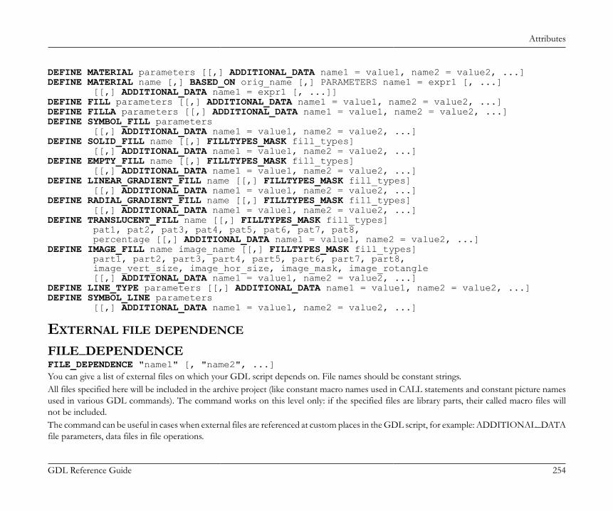
Attributes
GDL Reference Guide 254
DEFINE MATERIAL parameters [[,] ADDITIONAL_DATA name1 = value1, name2 = value2, ...]DEFINE MATERIAL name [,] BASED_ON orig_name [,] PARAMETERS name1 = expr1 [, ...] [[,] ADDITIONAL_DATA name1 = expr1 [, ...]]DEFINE FILL parameters [[,] ADDITIONAL_DATA name1 = value1, name2 = value2, ...]DEFINE FILLA parameters [[,] ADDITIONAL_DATA name1 = value1, name2 = value2, ...]DEFINE SYMBOL_FILL parameters [[,] ADDITIONAL_DATA name1 = value1, name2 = value2, ...]DEFINE SOLID_FILL name [[,] FILLTYPES_MASK fill_types] [[,] ADDITIONAL_DATA name1 = value1, name2 = value2, ...]DEFINE EMPTY_FILL name [[,] FILLTYPES_MASK fill_types] [[,] ADDITIONAL_DATA name1 = value1, name2 = value2, ...]DEFINE LINEAR_GRADIENT_FILL name [[,] FILLTYPES_MASK fill_types] [[,] ADDITIONAL_DATA name1 = value1, name2 = value2, ...]DEFINE RADIAL_GRADIENT_FILL name [[,] FILLTYPES_MASK fill_types] [[,] ADDITIONAL_DATA name1 = value1, name2 = value2, ...]DEFINE TRANSLUCENT_FILL name [[,] FILLTYPES_MASK fill_types] pat1, pat2, pat3, pat4, pat5, pat6, pat7, pat8, percentage [[,] ADDITIONAL_DATA name1 = value1, name2 = value2, ...]DEFINE IMAGE_FILL name image_name [[,] FILLTYPES_MASK fill_types] part1, part2, part3, part4, part5, part6, part7, part8, image_vert_size, image_hor_size, image_mask, image_rotangle [[,] ADDITIONAL_DATA name1 = value1, name2 = value2, ...]DEFINE LINE_TYPE parameters [[,] ADDITIONAL_DATA name1 = value1, name2 = value2, ...]DEFINE SYMBOL_LINE parameters [[,] ADDITIONAL_DATA name1 = value1, name2 = value2, ...]
EXTERNAL FILE DEPENDENCE
FILE_DEPENDENCEFILE_DEPENDENCE "name1" [, "name2", ...]You can give a list of external files on which your GDL script depends on. File names should be constant strings.All files specified here will be included in the archive project (like constant macro names used in CALL statements and constant picture namesused in various GDL commands). The command works on this level only: if the specified files are library parts, their called macro files willnot be included.The command can be useful in cases when external files are referenced at custom places in the GDL script, for example: ADDITIONAL_DATAfile parameters, data files in file operations.

Non-Geometric Scripts
GDL Reference Guide 255
NON-GEOMETRIC SCRIPTSIn addition to the 3D and 2D script windows that define the appearance of the GDL Object, further scripts are available for addingcomplementary information to it. These are the Properties Script used for quantity calculations, the Parameter Script that includes the list ofpossible values for different parameters, and the User Interface Script for creating a custom interface for parameter entry, Forward MigrationScript and Backward Migration Scripts to define how to migrate an old instance forward to the actual element or how to migrate the elementbackward to an older one. The commands available for all these script types are detailed on the following pages.
THE PROPERTIES SCRIPTLibrary parts have a GDL window reserved for the Properties script. This script allows you to make library part properties dependent onparameters, and, through a directive, define their place in the final component list. By using a few commands, it is possible to define in thescript local descriptors and components. Descriptors and components from external databases can also be referenced. Code lengths cannotexceed 32 characters.In the Properties script, you can use any GDL command that does not generate a shape.
DATABASE_SETDATABASE_SET set_name [, descriptor_name, component_name, unit_name, key_name, criteria_name, list_set_name]Database set definition or Database set selection. If this command is placed in a MASTER_GDL script, it will define a Database set containingDescriptor, Component, Unit, Key, Criteria and List Scheme files.This Database set name can then be referenced from Properties Scripts using the same command with only the set_name parameter as adirective, by selecting the actual Database set that REF COMPONENTs and REF DESCRIPTORs refer to. The default Database set nameis "Default Set", and will be used if no other set has been selected. The default Database set file names are: DESCDATA, COMPDATA,COMPUNIT, LISTKEY, LISTCRIT, LISTSET. All these names get translated in localized ARCHICAD versions.Scripts can include any number of DATABASE_SET selections.set_name: database set name.descriptor_name: descriptor data file name.component_name: component data file name.unit_name: unit data file name.key_name: key data file name.

Non-Geometric Scripts
GDL Reference Guide 256
criteria_name: criteria file name.list_set_name: list Scheme file name.
DESCRIPTORDESCRIPTOR name [, code, keycode]Local descriptor definition. Scripts can include any number of DESCRIPTORs.name: can extend to more than one line. New lines can be defined by the character '\n' and tabulators by '\t'. Adding '\' to the end of a line
allows you to continue the string in the next line without adding a new line. Inside the string, if the '\' character is doubled (\\), it will loseits control function and simply mean '\'. The length of the string (including the new line characters) cannot exceed 255 characters: additionalcharacters will be simply cut by the compiler. If you need a longer text, use several DESCRIPTORs.
code: string, defines a code for the descriptor.keycode: string, reference to a key in an external database.The key will be assigned to the descriptor.
REF DESCRIPTORREF DESCRIPTOR code [, keycode]Reference by code and keycode string to a descriptor in an external database.
COMPONENTCOMPONENT name, quantity, unit [, proportional_with, code, keycode, unitcode]Local component definition. Scripts can include any number of COMPONENTs.name: the name of the component (max. 128 characters).quantity: a numeric expression.unit: the string used for unit description.proportional_with: a code between 1 and 6. When listing, the component quantity defined above will be automatically multiplied
by a value calculated for the current listed element:1: item,2: length,3: surface A,4: surface B,5: surface,

Non-Geometric Scripts
GDL Reference Guide 257
6: volume.code: string, defines a code for the component.keycode: string, reference to a key in an external database. The key will be assigned to the component.unitcode: string, reference to a unit in an external database that controls the output format of the component quantity. This will replace
the locally defined unit string.
REF COMPONENTREF COMPONENT code [, keycode [, numeric_expression]]Reference by code and keycode string to a component in an external database. The value to multiply by in the component database can beoverwritten by the optional numeric expression specified here.
BINARYPROPBINARYPROPBinaryprop is a reference to the binary properties data (components and descriptors) defined in the library part in the Components andDescriptors sections.DATABASE_SET directives have no effect on the binary data.
SURFACE3DSURFACE3D ()The Surface 3D () function gives you the surface of the 3D shape of the library part.Warning: If you place two or more shapes in the same location with the same parameters, this function will give you the total sum of all shapes’surfaces.
VOLUME3DVOLUME3D ()The Volume 3D () function gives you the volume of the 3D shape of the library part.Warning: If you place two or more shapes in the same location with the same parameters, this function will give you the total sum of all shapes’volumes.
POSITIONPOSITION position_keywordEffective only in the Component List.

Non-Geometric Scripts
GDL Reference Guide 258
Changes only the type of the element the following descriptors and components are associated to. If there are no such directives in the Propertiesscript, descriptors and components will be listed with their default element types.position_keyword: keywords are the following:WALLSCOLUMNSBEAMSDOORSWINDOWSOBJECTSCEILSPITCHED_ROOFSLIGHTSHATCHESROOMSMESHES
A directive remains valid for all succeeding DESCRIPTORs and COMPONENTs until the next directive is ascribed. A script can include anynumber of directives.
Example:DESCRIPTOR "\tPainted box.\n\t Properties:\n\\t\t - swinging doors\n\\t\t - adjustable height\n\\t\t - scratchproof"REF DESCRIPTOR "0001"s = SURFACE3D () !wardrobe surfaceCOMPONENT "glue", 1.5, "kg"COMPONENT "handle", 2*c, "nb" !c number of doorsCOMPONENT "paint", 0.5*s, "kg"POSITION WALLSREF COMPONENT "0002"
DRAWINGDRAWINGDRAWING: Refers to the drawing described in the 2D script of the same library part. Use it to place drawings in your bill of materials.
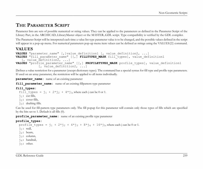
Non-Geometric Scripts
GDL Reference Guide 259
THE PARAMETER SCRIPTParameter lists are sets of possible numerical or string values. They can be applied to the parameters as defined in the Parameter Script of theLibrary Part, in the ARCHICAD_LibraryMaster object or the MASTER_GDL script. Type compatibility is verified by the GDL compiler.The Parameter Script will be interpreted each time a value list type parameter value is to be changed, and the possible values defined in the scriptwill appear in a pop-up menu. For numerical parameters pop-up menu item values can be defined as strings using the VALUES{2} command.
VALUESVALUES "parameter_name" [,]value_definition1 [, value_definition2, ...]VALUES "fill_parameter_name" [[,] FILLTYPES_MASK fill_types], value_definition1 [, value_definition2, ...]VALUES "profile_parameter_name" [[,] PROFILETYPES_MASK profile_types], value_definition1 [, value_definition2, ...]Defines a value restriction for a parameter (except dictionary types). The command has a special syntax for fill type and profile type parameters.If used on an array parameter, the restriction will be applied to all items individually.parameter_name: name of an existing parameterfill_parameter_name: name of an existing fillpattern type parameterfill_types:fill_types = j1 + 2*j2 + 4*j3, where each j can be 0 or 1.j1: cut fills,j2: cover fills,j3: drafting fills.
Can be used for fill-pattern type parameters only. The fill popup for this parameter will contain only those types of fills which are specifiedby the bits set to 1. Default is all fills (0).profile_parameter_name: name of an existing profile type parameterprofile_types:profile_types = j1 + 2*j2 + 4*j3 + 8*j4 + 16*j5, where each j can be 0 or 1.j1: wall,j2: beam,j3: column,j4: handrail,j5: other.

Non-Geometric Scripts
GDL Reference Guide 260
Can be set for profile type parameters only. The value list for any profile type parameter includes all existing profiles of the planfile automatically,no individual VALUES definition is needed. Using VALUES without masking (0) has the exact same result. Using VALUES with maskingcan filter the value list, leaving only the corresponding profiles of the bits set to 1. Individual profile indexes can be listed as regular valuedefinitions as well.value_definitioni: value definition, can be:expression: numerical or string expression, orCUSTOM: keyword, meaning that any custom value can be entered, orRANGE: range definition, with optional stepRANGE left_delimiter[lower_limit], [upper_limit]right_delimiter [STEP step_start_value,step_value]
left_delimiter: [, meaning >=, or (, meaning >; lower_limit: lower limit expression; upper_limit: upper limit expression; right_delimiter: ],meaning <=, or ), meaning <; step_start_value: starting value; step_value: step value.
VALUES{2}VALUES{2} "parameter_name" [,]num_expression1, description1, [, num_expression2, description2, ...]VALUES{2} "parameter_name" [,]num_values_array1, descriptions_array1 [, num_values_array2, descriptions_array2, ...]parameter_name: name of an existing angle, length, real, or integer type parameternum_expressioni, num_values_arrayi: simple value definition for a numerical parameter, or array expression containing
multiple numerical values. Available only for VALUES{2}descriptioni, descriptions_arrayi: description string of the numerical value i, or array expression containing multiple
description strings of the values defined by num_values_arrayi (array dimensions must match). Available only for VALUES{2}
Example 1: Simple value listsVALUES "par1" 1, 2, 3VALUES "par2" "a", "b"VALUES "par3" 1, CUSTOM, SIN (30)VALUES "par4" 4, RANGE(5, 10], 12, RANGE(,20] STEP 14.5, 0.5, CUSTOM

Non-Geometric Scripts
GDL Reference Guide 261
Example 2: Read all string values from a file for use in a value listDIM sarray[]! file in the library, containing parameter datafilename = "ProjectNotes.txt"ch1 = OPEN ("text", filename, "MODE=RO, LIBRARY")i = 1j = 1sarray[1] = ""! collect all stringsDO n = INPUT (ch1, i, 1, var) IF n > 0 AND VARTYPE (var) = 2 THEN sarray[j] = var j = j + 1 ENDIF i = i + 1WHILE n > 0CLOSE ch1! parameter popup with strings read from the fileVALUES "RefNote" sarray
PARAMETERSPARAMETERS name1 = expression1 [, name2 = expression2, ..., namen = expressionn]namei: the name of the parameter.expressioni: the new value of the parameter.Using this command, the parameter values of a Library Part can be modified by the Parameter Script.The modification will only be effective for the next interpretation. Commands in macros refer to the caller’s parameters. If the parameter is avalue list, the value chosen will be either an existing value, the custom value, or the first value from the value list.In addition, the global string variable GLOB_MODPAR_NAME contains the name of the last user-modified parameter.
LOCKLOCK "name1" [, "name2", ..., "namen"]Locks the named parameter(s) in the settings dialog box. A locked parameter will appear grayed in the dialog box and its value cannot bemodified by the user.

Non-Geometric Scripts
GDL Reference Guide 262
namen: string expression, name of the parameter to be locked.Compatibility: starting from ARCHICAD 22, the locking/hiding of selected ARCHICAD interface controls is extended.The extended feature can be activated with "Enable hide/lock of specific fix named optional parameters" setting (see "Details/CompatibilityOptions" dialog of the object in the Library Part Editor). The extended selection contains fix named optional parameters corresponding to:• standard text handling controls of "Text Style" settings dialog panel - see the section called “Parameters for Text Handling”,• extended label styling controls of "Text Style" settings dialog panel in Label tool - see the section called “Parameters for Labels”,• and selected label pointer controls of "Pointer" settings dialog panel - see the section called “Parameters for Labels”.LOCK ALL ["name1" [, "name2", ..., "namen"]]Locks all parameters in the settings dialog box, except those listed after the ALL keyword.
HIDEPARAMETERHIDEPARAMETER "name1" [, "name2", ..., "namen"]Hides the named parameter(s) and its child parameters in the settings dialog box. A parameter hidden using this command in the parameterscript will automatically disappear from the parameter list.namen: string expression, name of the parameter to be hidden.Compatibility: starting from ARCHICAD 22, the locking/hiding of selected ARCHICAD interface controls is extended. For details, see the LOCK command.HIDEPARAMETER ALL ["name1" [, "name2", ..., "namen"]]Hides all parameters and its child parameters in the settings dialog box, except those (and their children) listed after the ALL keyword.
THE USER INTERFACE SCRIPTUsing the following GDL commands, you can define a custom interface for a Library Part’s Custom Settings panel in the settings dialog box.If you click the Set as default button in the Library Part editor, the custom interface will be used by default in the Object’s (Door’s, Window’s,etc.) settings dialog box. Parameters with custom control are not hidden automatically on the original parameter list, but they can be hiddenmanually in the library part editor.
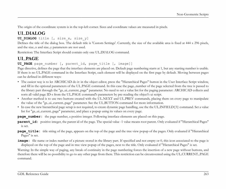
Non-Geometric Scripts
GDL Reference Guide 263
The origin of the coordinate system is in the top-left corner. Sizes and coordinate values are measured in pixels.
UI_DIALOGUI_DIALOG title [, size_x, size_y]Defines the title of the dialog box. The default title is 'Custom Settings'. Currently, the size of the available area is fixed at 444 x 296 pixels,and the size_x and size_y parameters are not used.Restriction: The Interface Script should contain only one UI_DIALOG command.
UI_PAGEUI_PAGE page_number [, parent_id, page_title [, image]]Page directive, defines the page that the interface elements are placed on. Default page numbering starts at 1, but any starting number is usable.If there is no UI_PAGE command in the Interface Script, each element will be displayed on the first page by default. Moving between pagescan be defined in different ways:• The easiest way is to let ARCHICAD do it: in the object editor, press the "Hierarchical Pages" button in the User Interface Script window,
and fill in the optional parameters of the UI_PAGE command. In this case the page_number of the page selected from the tree is passed tothe library part through the "gs_ui_current_page" parameter. No need to set a value list for the paging parameter: ARCHICAD collects andsorts all valid page ID-s from the UI_PAGE command's parameters by pre-reading the object's ui script.
• Another method is to use two buttons created with the UI_NEXT and UI_PREV commands, placing them on every page to manipulatethe value of the "gs_ui_current_page" parameter. See the UI_BUTTON command for more information.
• In case the new hierarchical page setup is not required, to create dynamic page handling, use the the UI_INFIELD{3} command. Set a valuelist for "gs_ui_current_page" parameter, and place a popup using its values on every page.
page_number: the page number, a positive integer. Following interface elements are placed on this page.parent_id: positive integer, the parent id of the page. The special value -1 value means root parent. Only evaluated if "Hierarchical Pages"
is set.page_title: title string of the page, appears on the top of the page and the tree view popup of the pages. Only evaluated if "Hierarchical
Pages" is set.image: file name or index number of a picture stored in the library part. If specified and not empty or 0, this icon associated to the page is
displayed on the top of the page and in tree view popup of the pages, next to the title. Only evaluated if "Hierarchical Pages" is set.Warning: In the simple way of paging, any break of continuity in the page numbering forces the insertion of a new page without buttons, andtherefore there will be no possibility to go to any other page from there. This restriction can be circumvented using the UI_CURRENT_PAGEcommand.
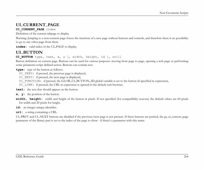
Non-Geometric Scripts
GDL Reference Guide 264
UI_CURRENT_PAGEUI_CURRENT_PAGE indexDefinition of the current tabpage to display.Warning: Jumping to a non-existent page forces the insertion of a new page without buttons and controls, and therefore there is no possibilityto go to any other page from there.index: valid index of the UI_PAGE to display.
UI_BUTTONUI_BUTTON type, text, x, y [, width, height, id [, url]]Button definition on current page. Buttons can be used for various purposes: moving from page to page, opening a web page or performingsome parameter-script defined action. Buttons can contain text.type: type of the button as follows:UI_PREV: if pressed, the previous page is displayed,UI_NEXT: if pressed, the next page is displayed,UI_FUNCTION: if pressed, the GLOB_UI_BUTTON_ID global variable is set to the button id specified in expression,UI_LINK: if pressed, the URL in expression is opened in the default web browser,
text: the text that should appear on the button.x, y: the position of the button.width, height: width and height of the button in pixels. If not specified (for compatibility reasons) the default values are 60 pixels
for width and 20 pixels for height.id: an integer unique identifier.url: a string containing a URL.UI_PREV and UI_NEXT buttons are disabled if the previous/next page is not present. If these buttons are pushed, the gs_ui_current_pageparameter of the library part is set to the index of the page to show - if there’s a parameter with this name.
Non-Geometric Scripts
GDL Reference Guide 265
Example:! UI scriptUI_CURRENT_PAGE gs_ui_current_pageUI_BUTTON UI_FUNCTION, "Go to page 9", 200,150, 70,20, 3UI_BUTTON UI_LINK, "Visit Website", 200,180, 100,20, 0, "https://www.graphisoft.com"! parameter scriptif GLOB_UI_BUTTON_ID = 3 then parameters gs_ui_current_page = 9, ...endif
UI_PICT_BUTTONUI_PICT_BUTTON type, text, picture_reference, x, y, width, height [, id [, url]]Similar to the UI_BUTTON command. But this type of buttons can contain pictures.picture_reference: file name or index number of the picture stored in the library part. The index 0 refers to the preview picture of
the library part. Pixel transparency is allowed in the picture.text: has no effect for picture buttons.
UI_SEPARATORUI_SEPARATOR x1, y1, x2, y2Generates a separator rectangle. The rectangle becomes a single (vertical or horizontal) separator line if x1 = x2 or y1 = y2x1, y1: upper left node coordinates (starting point coordinates of the line).x2, y2: lower right node coordinates (endpoint coordinates of the line).
UI_GROUPBOXUI_GROUPBOX text, x, y, width, heightA groupbox is a rectangular separator with caption text. It can be used to visually group logically related parameters.text: the title of the groupbox.x, y: the position of upper left corner.width, height: width and height in pixels.

Non-Geometric Scripts
GDL Reference Guide 266
UI_PICTUI_PICT picture_reference, x, y [, width, height [, mask]]Picture element in the dialog box. The picture file must be located in one of the loaded libraries.picture_reference: file name or index number of the picture stored in the library part. The index 0 refers to the preview picture
of the library part.x, y: position of the top left corner of the picture.width, height: optional width and height in pixels; by default, the picture’s original width and height values will be used.mask: alpha + distortion.See the PICTURE command for full explanation.
UI_STYLEUI_STYLE fontsize, face_codeAll the UI_OUTFIELDs and UI_INFIELDs generated after this keyword will represent this style until the next UI_STYLE statement.fontsize: one of the following font size values:0: small,1: extra small,2: large.
face_code: similar to the DEFINE STYLE command, but the values cannot be used in combination.0: normal,1: bold,2: italic,4: underline.
UI_OUTFIELDUI_OUTFIELD expression, x, y [, width, height [, flags]]Generates a static text.expression: numerical or string expression.x, y: position of the text block’s top left corner.width, height: width and height of the text box. If omitted, the text box will wrap around the text as tight as possible for the given font.flags:
Non-Geometric Scripts
GDL Reference Guide 267
flags = j1 + 2*j2 + 4*j3, where each j can be 0 or 1.j1: horizontal alignment (with j2),j2: horizontal alignment (with j1):j1 = 0, j2 = 0: Aligns to the left edge (default),j1 = 1, j2 = 0: Aligns to the right edge,j1 = 0, j2 = 1: Aligns to the center,j1 = 1, j2 = 1: Not used,j3: grayed text.
UI_INFIELDUI_INFIELD "name", x, y, width, height [, method, picture_name, images_number, rows_number, cell_x, cell_y, image_x, image_y, expression_image1, text1, ... expression_imagen, textn]
UI_INFIELD{2}UI_INFIELD{2} name, x, y, width, height [, method, picture_name, images_number, rows_number, cell_x, cell_y, image_x, image_y, expression_image1, text1, ... expression_imagen, textn]
Non-Geometric Scripts
GDL Reference Guide 268
UI_INFIELD{3}UI_INFIELD{3} name, x, y, width, height [, method, picture_name, images_number, rows_number, cell_x, cell_y, image_x, image_y, expression_image1, text1, value_definition1, ... [picIdxArray, textArray, valuesArray, ...] expression_imagen, textn, value_definitionn]
UI_INFIELD{4}UI_INFIELD{4} "name", x, y, width, height [, method, picture_name, images_number, rows_number, cell_x, cell_y, image_x, image_y, expression_image1, text1, value_definition1, ... [picIdxArray, textArray, valuesArray, ...] expression_imagen, textn, value_definitionn]Generates an edit text or a pop-up menu for the parameter input. A pop-up is generated if the parameter type is value list, material, fill, linetype or pencolor.If the optional parameters of the command are present, value lists can be alternatively displayed as thumbnail view fields. Different thumbnailcontrol types are available. They display the specified images and associated texts and allow the selection of one single item at a time, just likein a pop-up menu.In the version 1 and 2 infield, the thumbnail items and the value list items are associated by indices.The version 3 and version 4 infield defines value association which binds the thumbnail items to value list items of the associated parameter.If a value defined in a thumbnail item isn’t present in the parameter’s value list, it won’t be displayed in the control. Identical sized arrays canbe used for lines of definition as well.The Interface Script is rebuilt with the new value after any parameter is modified.name: parameter name as string expression (all 4 command versions), with parameter name option for UI_INFIELD{2} and
UI_INFIELD{3}, and parameter name as text array value option for UI_INFIELD{4}.
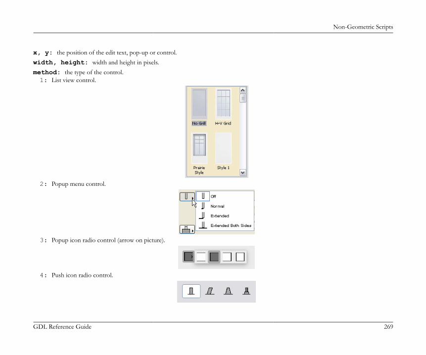
Non-Geometric Scripts
GDL Reference Guide 269
x, y: the position of the edit text, pop-up or control.width, height: width and height in pixels.method: the type of the control.1: List view control.
2: Popup menu control.
3: Popup icon radio control (arrow on picture).
4: Push icon radio control.

Non-Geometric Scripts
GDL Reference Guide 270
5: Pushbutton with text.
6: Pushbutton with picture.
7: Checkbox with text.
8: Popup list with text.
9: Popup icon radio control (arrow next to picture).
picture_name: name of the common image file containing a matrix of concatenated images, or empty string.images_number: number of images in the matrix, for boolean parameters it can be 0 or 2.rows_number: number of rows of the matrix.cell_x, cell_y: width and height of a cell within the thumbnail view field, including image and text.image_x, image_y: width and height of the image in the cell.

Non-Geometric Scripts
GDL Reference Guide 271
expression_imagei: index of image number i in the matrix, or individual file name. If a common image file name was specified, indicesmust be used here. Combination of indices and individual file names does not work.
texti: text in cell number i.value_definitioni: value definition which matches the cell with a value list item by value:expression: numerical or string expression, orCUSTOM: keyword, meaning that any custom value can be entered.
picIdxArray: Dynamic array of picture names (strings) or indexes (integers) in cells. Do not use mixed types in arraytextArray: Dynamic array of texts in cellsvalueArray: Dynamic array of parameter values in cells
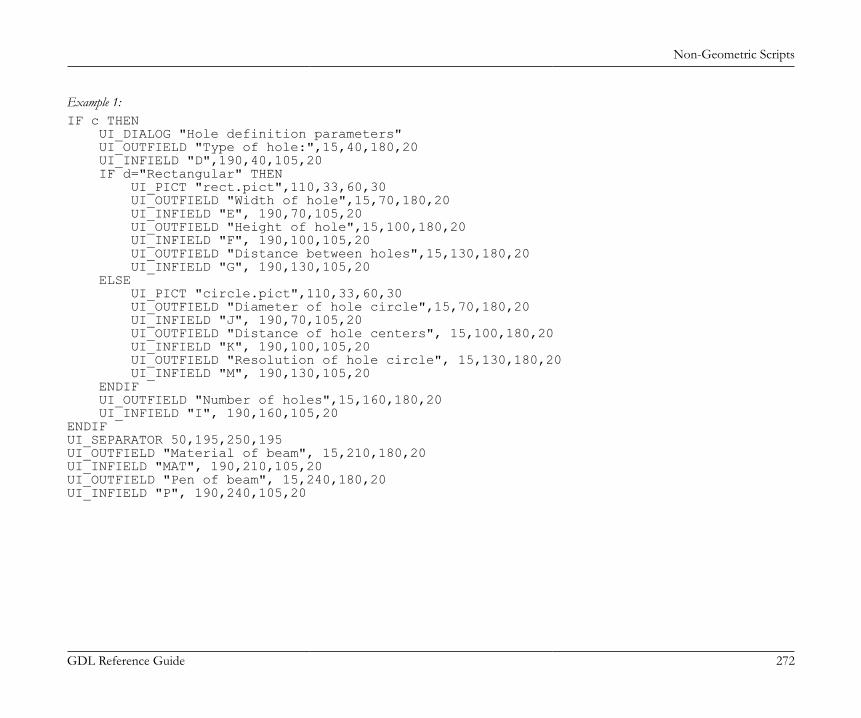
Non-Geometric Scripts
GDL Reference Guide 272
Example 1:IF c THEN UI_DIALOG "Hole definition parameters" UI_OUTFIELD "Type of hole:",15,40,180,20 UI_INFIELD "D",190,40,105,20 IF d="Rectangular" THEN UI_PICT "rect.pict",110,33,60,30 UI_OUTFIELD "Width of hole",15,70,180,20 UI_INFIELD "E", 190,70,105,20 UI_OUTFIELD "Height of hole",15,100,180,20 UI_INFIELD "F", 190,100,105,20 UI_OUTFIELD "Distance between holes",15,130,180,20 UI_INFIELD "G", 190,130,105,20 ELSE UI_PICT "circle.pict",110,33,60,30 UI_OUTFIELD "Diameter of hole circle",15,70,180,20 UI_INFIELD "J", 190,70,105,20 UI_OUTFIELD "Distance of hole centers", 15,100,180,20 UI_INFIELD "K", 190,100,105,20 UI_OUTFIELD "Resolution of hole circle", 15,130,180,20 UI_INFIELD "M", 190,130,105,20 ENDIF UI_OUTFIELD "Number of holes",15,160,180,20 UI_INFIELD "I", 190,160,105,20ENDIFUI_SEPARATOR 50,195,250,195UI_OUTFIELD "Material of beam", 15,210,180,20UI_INFIELD "MAT", 190,210,105,20UI_OUTFIELD "Pen of beam", 15,240,180,20UI_INFIELD "P", 190,240,105,20

Non-Geometric Scripts
GDL Reference Guide 273
Example 2:! Parameter Script:VALUES "myParameter" "Two", "Three", "Five", CUSTOM
! Interface Script:px = 80py = 60cx = px + 3cy = py + 25
UI_INFIELD{3} "myParameter", 10, 10, 4 * cx + 21, cy + 5, 1, "myPicture", 6, 1, cx, cy, px, py, 1, "1 - one", "One", 2, "2 - two", "Two", 3, "3 - three", "Three", 4, "4 - four", "Four", 5, "5 - five", "Five", 6, "custom value", CUSTOM
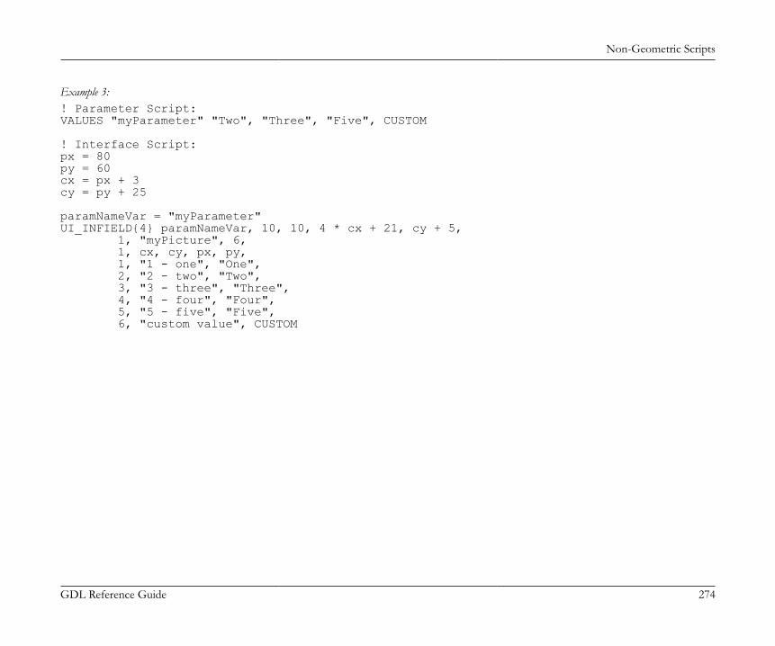
Non-Geometric Scripts
GDL Reference Guide 274
Example 3:! Parameter Script:VALUES "myParameter" "Two", "Three", "Five", CUSTOM
! Interface Script:px = 80py = 60cx = px + 3cy = py + 25
paramNameVar = "myParameter"UI_INFIELD{4} paramNameVar, 10, 10, 4 * cx + 21, cy + 5, 1, "myPicture", 6, 1, cx, cy, px, py, 1, "1 - one", "One", 2, "2 - two", "Two", 3, "3 - three", "Three", 4, "4 - four", "Four", 5, "5 - five", "Five", 6, "custom value", CUSTOM
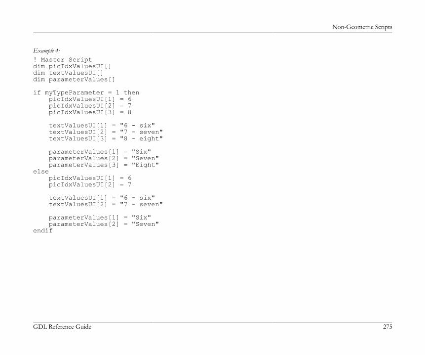
Non-Geometric Scripts
GDL Reference Guide 275
Example 4:! Master Scriptdim picIdxValuesUI[]dim textValuesUI[]dim parameterValues[]
if myTypeParameter = 1 then picIdxValuesUI[1] = 6 picIdxValuesUI[2] = 7 picIdxValuesUI[3] = 8
textValuesUI[1] = "6 - six" textValuesUI[2] = "7 - seven" textValuesUI[3] = "8 - eight"
parameterValues[1] = "Six" parameterValues[2] = "Seven" parameterValues[3] = "Eight"else picIdxValuesUI[1] = 6 picIdxValuesUI[2] = 7
textValuesUI[1] = "6 - six" textValuesUI[2] = "7 - seven"
parameterValues[1] = "Six" parameterValues[2] = "Seven"endif
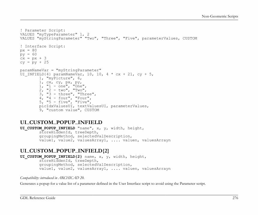
Non-Geometric Scripts
GDL Reference Guide 276
! Parameter Script:VALUES "myTypeParameter" 1, 2VALUES "myStringParameter" "Two", "Three", "Five", parameterValues, CUSTOM
! Interface Script:px = 80py = 60cx = px + 3cy = py + 25
paramNameVar = "myStringParameter"UI_INFIELD{4} paramNameVar, 10, 10, 4 * cx + 21, cy + 5, 1, "myPicture", 6, 1, cx, cy, px, py, 1, "1 - one", "One", 2, "2 - two", "Two", 3, "3 - three", "Three", 4, "4 - four", "Four", 5, "5 - five", "Five", picIdxValuesUI, textValuesUI, parameterValues, 9, "custom value", CUSTOM
UI_CUSTOM_POPUP_INFIELDUI_CUSTOM_POPUP_INFIELD "name", x, y, width, height, storeHiddenId, treeDepth, groupingMethod, selectedValDescription, value1, value2, valuesArray1, .... valuen, valuesArrayn
UI_CUSTOM_POPUP_INFIELD{2}UI_CUSTOM_POPUP_INFIELD{2} name, x, y, width, height, storeHiddenId, treeDepth, groupingMethod, selectedValDescription, value1, value2, valuesArray1, .... valuen, valuesArrayn Compatibility: introduced in ARCHICAD 20.Generates a popup for a value list of a parameter defined in the User Interface script to avoid using the Parameter script.

Non-Geometric Scripts
GDL Reference Guide 277
Suitable for lists which can not be requested in Parameter script. For the parameter script restrictions see the section called “REQUEST Options”.name: parameter name as string expression for UI_CUSTOM_POPUP_INFIELD or parameter name with optional actual index values
if array for UI_CUSTOM_POPUP_INFIELD{2}.x, y: the position of the edit text, pop-up.width, height: width and height in pixels.storeHiddenId, treeDepth: to set up automatic or manual trees.storeHiddenId = 0, treeDepth = 0: works only with array parameters.The "treeDepth" parameter is set automatically by the second dimension (number of columns) of the array.storeHiddenId = 1, treeDepth > 0: works only with single parameters.There must be n * (1 + treeDepth) values defined (first one for the stored ID and the rest for defining the custom tree).
groupingMethod: grouping method for sorting the tree.1: does not sort the groups and values under the same parent.
2: sorts the groups and values under the same parent.

Non-Geometric Scripts
GDL Reference Guide 278
selectedValDescription: the text written in the field, if empty string the text will be the stored ID of the selected item.valuei, valuesArrayi: define tree values one-by-one and/or with a one dimension array.
Example:
UI_CUSTOM_POPUP_INFIELD "stParameterName", x, y, width, height, 1, 3, 2, "", ! storeHiddenId, treeDepth, groupingMethod, selectedValDescription "hiddenID1", "type1", "group1", "value1", "hiddenID2", "type1", "group1", "value2", "hiddenID3", "type2", "group2", "value1", "hiddenID4", "type2", "group2", "value2", "hiddenID5", "type2", "", "value3", "hiddenID6", "", "", "value4", "hiddenID7", "", "", "value5"

Non-Geometric Scripts
GDL Reference Guide 279
UI_RADIOBUTTONUI_RADIOBUTTON name, value, text, x, y, width, height
UI_RADIOBUTTON{2}UI_RADIOBUTTON{2} "name", value, text, x, y, width, heightVersion {2} compatibility: introduced in ARCHICAD 20.Generates a radio button of a radio button group. Radio button groups are defined by the parameter name. Items in the same group aremutually exclusive.name: parameter name or name as string expression for UI_RADIOBUTTON and parameter name as string expression (or text array
indexed value) for UI_RADIOBUTTON{2}.value: parameter is set to this value if this radio button is set.text: this text is displayed beside the radio button.x, y: the position of the radio control.width, height: width and height in pixels.
Example:UI_RADIOBUTTON "ceilingPlan", 0, `Floor Plan`, 10, 140, 100, 20UI_RADIOBUTTON "ceilingPlan", 1, `Ceiling Plan`, 10, 160, 100, 20
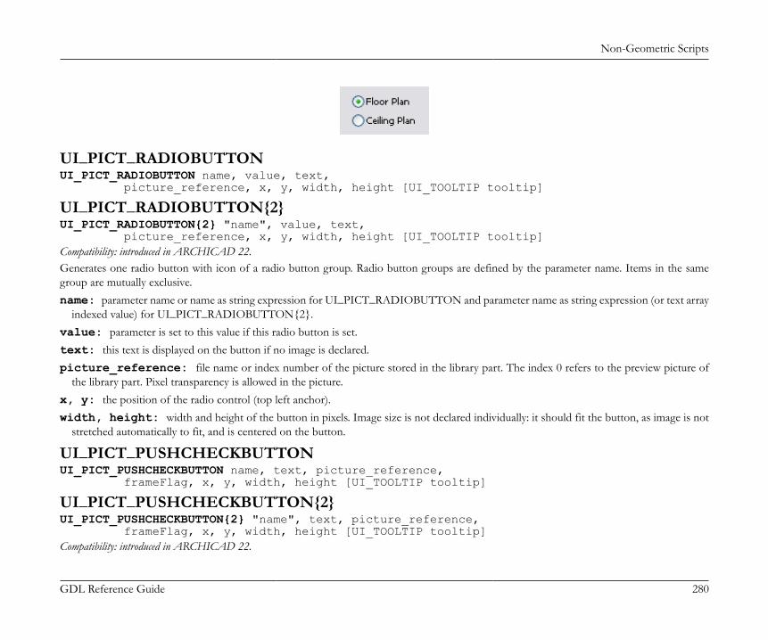
Non-Geometric Scripts
GDL Reference Guide 280
UI_PICT_RADIOBUTTONUI_PICT_RADIOBUTTON name, value, text, picture_reference, x, y, width, height [UI_TOOLTIP tooltip]
UI_PICT_RADIOBUTTON{2}UI_PICT_RADIOBUTTON{2} "name", value, text, picture_reference, x, y, width, height [UI_TOOLTIP tooltip]Compatibility: introduced in ARCHICAD 22.Generates one radio button with icon of a radio button group. Radio button groups are defined by the parameter name. Items in the samegroup are mutually exclusive.name: parameter name or name as string expression for UI_PICT_RADIOBUTTON and parameter name as string expression (or text array
indexed value) for UI_PICT_RADIOBUTTON{2}.value: parameter is set to this value if this radio button is set.text: this text is displayed on the button if no image is declared.picture_reference: file name or index number of the picture stored in the library part. The index 0 refers to the preview picture of
the library part. Pixel transparency is allowed in the picture.x, y: the position of the radio control (top left anchor).width, height: width and height of the button in pixels. Image size is not declared individually: it should fit the button, as image is not
stretched automatically to fit, and is centered on the button.
UI_PICT_PUSHCHECKBUTTONUI_PICT_PUSHCHECKBUTTON name, text, picture_reference, frameFlag, x, y, width, height [UI_TOOLTIP tooltip]
UI_PICT_PUSHCHECKBUTTON{2}UI_PICT_PUSHCHECKBUTTON{2} "name", text, picture_reference, frameFlag, x, y, width, height [UI_TOOLTIP tooltip]Compatibility: introduced in ARCHICAD 22.

Non-Geometric Scripts
GDL Reference Guide 281
Generates one pushcheck button with icon for a boolean parameter. Similar to the UI_INFIELD{3} command with method 6, with additionaloption to control the visibility of the button frame.name: parameter name or name as string expression for UI_PICT_PUSHCHECKBUTTON and parameter name as string expression (or
text array indexed value) for UI_PICT_PUSHCHECKBUTTON{2}.text: this text is displayed on the button if no image is declared.picture_reference: file name or index number of the picture stored in the library part. The index 0 refers to the preview picture of
the library part. Pixel transparency is allowed in the picture.frameFlag: 1 - frame is displayed, 0 - frame is not visible. Use this option to match the control to other User Interface items in style.x, y: the position of the button (top left anchor).width, height: width and height of the button in pixels. Image size is not declared individually: it should fit the button, as image is not
stretched automatically to fit, and is centered on the button.
UI_TEXTSTYLE_INFIELDUI_TEXTSTYLE_INFIELD name, faceCodeMask, x, y, buttonWidth, buttonHeight[, buttonOffsetX]
UI_TEXTSTYLE_INFIELD{2}UI_TEXTSTYLE_INFIELD{2} "name", faceCodeMask, x, y, buttonWidth, buttonHeight [, buttonOffsetX]Compatibility: introduced in ARCHICAD 22.Generates a row of puschcheckbuttons specifically used to set font style via an integer parameter, with similar appearance as seen in the generalprogram interface. The format of the set value matches the input parameter of the DEFINE STYLE{2} command. Both icons and tooltipsare referenced from ARCHICAD itself, according to the localized version. The enabled buttons are displayed in a single-row arrangement.name: parameter name or name as string expression for UI_TEXTSTYLE_INFIELD and parameter name as string expression (or text
array indexed value) for UI_TEXTSTYLE_INFIELD{2}.faceCodeMask: used bits add the matching font style option to the control:faceCodeMask = j1 + 2*j2 + 4*j3 + 32*j6 + 64*j7 + 128*j8, where each j can be 0 or 1.j1: bold,j2: italic,j3: underline,j6: superscript,
Non-Geometric Scripts
GDL Reference Guide 282
j7: subscript,j8: strikethrough.If faceCodeMask = 0, then all possible font style buttons are displayed. In case of an invalid faceCodeMask, "Check Script" returns withwarning ("Invalid mask value used").
x, y: the position of the first button (top left anchor).buttonWidth, buttonHeight: width and height of one button in pixels. Full width can be calculated by using the faceCodeMask,
the buttonWidth and the buttonOffsetX values, if necessary.buttonOffsetX: distance between neighboring buttons in the row, in pixels. Automatic, if not set.
UI_LISTFIELDUI_LISTFIELD fieldID, x, y, width, height [, iconFlag [, description_header [, value_header]]]Generates a control for the parameter input as a scrollable list containing an arbitrary number of rows, with the following columns: icon,description and input field for the parameter value. Lines of the list can be defined with the UI_LISTITEM command. UI_LISTFIELD andUI_LISTITEM definitions can be scripted in an arbitrary order. Empty listfields (with no list items) are not displayed.fieldID: the unique identifier of the listfield. This ID also used in the UI_LISTITEM commands specifies the listfield the listitems belong
to. Duplicates within a user interface script are not allowed.x, y: position of the listfield's top left corner.width, height: width and height in pixels.iconFlag:iconFlag = 0: icon column is not generated for this listfield.iconFlag = 1: icon column is generated for this listfield (default value if not specified).
If the Custom Settings panel has only one control and this control is a listfield, the x, y, width, height parameters have no effect. In this casethe width of the listfield equals to the width of the Custom Settings panel.description_header: the title of the Description column.value_header: the title of the Value column.If both description_header and value_header are empty strings or not specified, the listfield is generated without a header. If the strings containat least one space, the listfield is generated with an empty header.
UI_LISTITEMUI_LISTITEM itemID, fieldID, "name" [, childFlag [, image [, paramDesc]]]

Non-Geometric Scripts
GDL Reference Guide 283
UI_LISTITEM{2}UI_LISTITEM{2} itemID, fieldID, name [, childFlag [, image [, paramDesc]]]Appends a listitem to the listfield defined by the fieldID parameter.itemID: the unique identifier of the listitem. Listitems can be scripted in an arbitrary order and are sorted by itemID. Duplicate listitem
IDs within a listfield are not allowed.fieldID: the unique identifier of the listfield containing this listitem.name: parameter name as string expression for UI_LISTITEM or parameter name with optional actual index values if array for
UI_LISTITEM{2}.childFlag:childFlag = 0: the listitem is a groupitem (default value if not specified).childFlag = 1: the listitem is a childitem. The parent item is the first groupitem above.
image: file name or index number of the picture stored in the library part. If valid, it is displayed as an icon in the first column of thelistfield in the associated listitem's row.
paramDesc: the visible name of the listitem in the Description column. If left empty, the description is automatically filled up from theparameter list description of the Library Part. If there is no description there, the name of the parameter is displayed instead.
If "name" string is empty, the listitem is a group with bold fonttype. If both "name" string and paramDesc are empty, the listitem is a separator.The HIDEPARAMETER command is ineffective for list items, the script should not add the item instead of using it. The LOCK commandcan be used and it is effective for list items.For a listfield it is recommended to define different itemIDs for different parameters, groups and separators.

Non-Geometric Scripts
GDL Reference Guide 284
Example:! List with header without icon column
ui_listfield 1, 10, 35, 432, 220, 0, "Description Header Text", "Value Header Text"
ui_listitem 1, 1, "", 0, "", "Group Title 1" ! Group Lineui_listitem 2, 1, "A", 1ui_listitem 3, 1, "B", 1ui_listitem 4, 1, "ZZYZX", 1
ui_listitem 5, 1, "" !separatorui_listitem 6, 1, "AC_show2DHotspotsIn3D", 0, "", "Group Title 2" ! Group Parameter Lineui_listitem 7, 1, "A", 1, "", "Custom Description A"ui_listitem 8, 1, "B", 1, "", "Custom Description B"ui_listitem 9, 1, "ZZYZX", 1, "", "Custom Description ZZYZX"
UI_CUSTOM_POPUP_LISTITEM
UI_CUSTOM_POPUP_LISTITEM itemID, fieldID, "name", childFlag, image, paramDesc, storeHiddenId, treeDepth, groupingMethod, selectedValDescription, value1, value2, valuesArray1, .... valuen, valuesArrayn

Non-Geometric Scripts
GDL Reference Guide 285
UI_CUSTOM_POPUP_LISTITEM{2}
UI_CUSTOM_POPUP_LISTITEM{2} itemID, fieldID, name, childFlag, image, paramDesc, storeHiddenId, treeDepth, groupingMethod, selectedValDescription, value1, value2, valuesArray1, .... valuen, valuesArrayn Compatibility: introduced in ARCHICAD 20.Similar to the "UI_CUSTOM_POPUP_INFIELD" and the "UI_CUSTOM_POPUP_INFIELD{2}"Generates a listitem with popup for a value list of a parameter defined in the User Interface script to avoid using the Parameter script.Suitable for lists which can not be requested in Parameter script. For the parameter script restrictions see the section called “REQUEST Options”.itemID: the unique identifier of the listitem. Listitems can be scripted in an arbitrary order and are sorted by itemID. Duplicate listitem
IDs within a listfield are not allowed.fieldID: the unique identifier of the listfield containing this listitem.name: parameter name as string expression for UI_CUSTOM_POPUP_LISTITEM or parameter name with optional actual index values
if array for UI_CUSTOM_POPUP_LISTITEM{2}.childFlag:childFlag = 0: the listitem is a groupitem (default value if not specified).childFlag = 1: the listitem is a childitem. The parent item is the first groupitem above.
image: file name or index number of the picture stored in the library part. If valid, it is displayed as an icon in the first column of thelistfield in the associated listitem's row.
paramDesc: the visible name of the listitem in the Description column. If left empty, the description is automatically filled up from theparameter list description of the Library Part. If there is no description there, the name of the parameter is displayed instead.
storeHiddenId, treeDepth: to set up automatic or manual trees.storeHiddenId = 0, treeDepth = 0: works only with array parameters.The "treeDepth" parameter is set automatically by the second dimension (number of columns) of the array.storeHiddenId = 1, treeDepth > 0: works only with single parameters.There must be n * (1 + treeDepth) values defined (first one for the stored ID and the rest for defining the custom tree).
groupingMethod: grouping method for sorting the tree.1: does not sort the groups and values under the same parent.

Non-Geometric Scripts
GDL Reference Guide 286
2: sorts the groups and values under the same parent.
selectedValDescription: the text written in the field, if empty string the text will be the stored ID of the selected item.valuei, valuesArrayi: define tree values one-by-one and/or with a one dimension array.
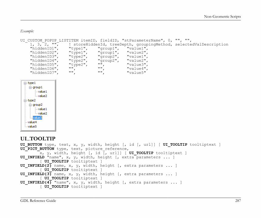
Non-Geometric Scripts
GDL Reference Guide 287
Example:
UI_CUSTOM_POPUP_LISTITEM itemID, fieldID, "stParameterName", 0, "", "", 1, 3, 2, "", ! storeHiddenId, treeDepth, groupingMethod, selectedValDescription "hiddenID1", "type1", "group1", "value1", "hiddenID2", "type1", "group1", "value2", "hiddenID3", "type2", "group2", "value1", "hiddenID4", "type2", "group2", "value2", "hiddenID5", "type2", "", "value3", "hiddenID6", "", "", "value4", "hiddenID7", "", "", "value5"
UI_TOOLTIPUI_BUTTON type, text, x, y, width, height [, id [, url]] [ UI_TOOLTIP tooltiptext ]UI_PICT_BUTTON type, text, picture_reference, x, y, width, height [, id [, url]] [ UI_TOOLTIP tooltiptext ]UI_INFIELD "name", x, y, width, height [, extra parameters ... ] [ UI_TOOLTIP tooltiptext ]UI_INFIELD{2} name, x, y, width, height [, extra parameters ... ] [ UI_TOOLTIP tooltiptext ]UI_INFIELD{3} name, x, y, width, height [, extra parameters ... ] [ UI_TOOLTIP tooltiptext ]UI_INFIELD{4} "name", x, y, width, height [, extra parameters ... ] [ UI_TOOLTIP tooltiptext ]

Non-Geometric Scripts
GDL Reference Guide 288
UI_CUSTOM_POPUP_INFIELD "name", x, y, width, height , extra parameters ... [ UI_TOOLTIP tooltiptext ]UI_CUSTOM_POPUP_INFIELD{2} name, x, y, width, height , extra parameters ... [ UI_TOOLTIP tooltiptext ]UI_RADIOBUTTON name, value, text, x, y, width, height [ UI_TOOLTIP tooltiptext ]UI_OUTFIELD expression, x, y, width, height [, flags] [ UI_TOOLTIP tooltiptext ]UI_PICT expression, x, y [, width, height [, mask]] [ UI_TOOLTIP tooltiptext ]UI_LISTFIELD fieldID, x, y, width, height [, iconFlag [, description_header [, value_header]]] [ UI_TOOLTIP tooltiptext ]UI_LISTITEM itemID, fieldID, "name" [, childFlag [, image [, paramDesc]]] [ UI_TOOLTIP tooltiptext ]UI_LISTITEM{2} itemID, fieldID, name [, childFlag [, image [, paramDesc]]] [ UI_TOOLTIP tooltiptext ]UI_CUSTOM_POPUP_LISTITEM itemID, fieldID, "name", childFlag , image , paramDesc, extra parameters ... [ UI_TOOLTIP tooltiptext ]UI_CUSTOM_POPUP_LISTITEM{2} itemID, fieldID, name, childFlag , image , paramDesc, extra parameters ... [ UI_TOOLTIP tooltiptext ]Defines the tooltip for the control on the user interface page. Tooltips are available for buttons, infields, outfields, listfields, listitems and picturesif they are not disabled by the user in the running context (e.g., in the Help menu of ARCHICAD).The listfield's tooltip appears in all included listitems if an item has none declared. The own tooltip of the listitem will take effect over thetooltip of the listfield (if existing) inline.tooltiptext: the text to display as tooltip for the control.
UI_COLORPICKERUI_COLORPICKER "redParamName", "greenParamName", "blueParamName", x0, y0 [, width [, height]]
UI_COLORPICKER{2}UI_COLORPICKER{2} redParamName, greenParamName, blueParamName, x0, y0 [, width [, height]]Color picker dialog to set the r, g, b components of a color and store them into the given parameters. These values can later be used in theLIGHT command.redParamName, greenParamName, blueParamName: parameter names as string expression for UI_COLORPICKER or
parameter names with optional actual index values if array for UI_COLORPICKER{2}x0, y0: position of the color picker's top left corner.

Non-Geometric Scripts
GDL Reference Guide 289
width, height: width and height in pixels.
UI_SLIDERUI_SLIDER "name", x0, y0, width, height [, nSegments [, sliderStyle]]
UI_SLIDER{2}UI_SLIDER{2} name, x0, y0, width, height [, nSegments [, sliderStyle]]Generates a slider control for an integer parameter defined with a range. For integer parameters with undefined range lower and upper limitvalues are -32768 (minimum signed short) and 32767 (maximum signed short).name: parameter name as string expression parameter or name with optional actual index values for UI_SLIDER{2}.x0, y0: position of the slider.width, height: slider width and height in pixels. If the width > height the slider is horizontal, in the opposite case it is vertical.nSegments: optional number of segments on the slider. If 0, no segments are displayed, if omitted or negative, the number of segments
are calculated from the range upper and lower limit values and the step defined for the parameter.sliderStyle: optional slider style (default is 0)0: slider points to the bottom (horizontal sliders) or to the right (vertical sliders).1: slider points to the top (horizontal sliders) or to the left (vertical sliders).
THE FORWARD MIGRATION SCRIPTIf an element is changed completely in a newer library, compatibility can be maintained by defining the migration logic. For more detailedinformation, please take a look at the section called “Forward Migration script”.

Non-Geometric Scripts
GDL Reference Guide 290
Example:
actualGUID = FROM_GUID
! ==============================================================================! Subroutines! ==============================================================================
_startID = "AAAA-AAAA-...AAA" _endID = "BBBB-BBBB-...BBB"gosub "migrationstepname_FWM"
! ==============================================================================! Set Migration GUID! ==============================================================================
setmigrationguid actualGUID
! ==============================================================================end ! end ! end ! end ! end ! end ! end ! end ! end ! end ! end ! end ! end ! en! ==============================================================================
! ==============================================================================! migrationstepname! =============================================================================="migrationstepname_FWM": if actualGuid = _startID then newParameter = oldParameter parameters newParameter = newParameter actualGuid = _endID endifreturn
FROM_GUID is the global variable holding the main ID of the original object which the migration is run on.In case the script succeeds, the instance gets substituted by the new element with the updated parameters.
SETMIGRATIONGUIDSETMIGRATIONGUID guid
Non-Geometric Scripts
GDL Reference Guide 291
The command tells the running environment, which element will be the matching migration element for the current object. If the returned IDbelongs to the current element, the migration of the object gets complete.
STORED_PAR_VALUESTORED_PAR_VALUE ("oldparname", outputvalue)Retrieves the value of a parameter, which is present in the migrated object, and present or deleted in the new version object. This commandform is suggested for those parameters present in the new object as well. To get the value of an old array Parameter, the outputvalue parametermust be initialized as an array (with the dim command).oldparname: string expression, name of the parameter in the old parameter list.outputvalue: output variable to store the value of the parameter.Return value: 1 on success, 0 otherwise (for example, if there is no parameter with that name in the parameter list of the old object). Duringchecking the script the return value is always 0, because the old Parameters section is not known.
DELETED_PAR_VALUEDELETED_PAR_VALUE ("oldparname", outputvalue)Retrieves the value of a parameter, which is present in the migrated object, and present or deleted in the new version object. This commandform is suggested for those parameters deleted from the new object. To get the value of an old array Parameter, the outputvalue parametermust be initialized as an array (with the dim command).oldparname: string expression, name of the parameter in the old parameter list.outputvalue: output variable to store the value of the parameter.Return value: 1 on success, 0 otherwise (for example, if there is no parameter with that name in the parameter list of the old object). Duringchecking the script the return value is always 0, because the old Parameters section is not known.
THE BACKWARD MIGRATION SCRIPTVia the Backward Migration script you can define the backward conversion logic converting new object instances to older ones. For more anddetailed information, please take a look at the section called “Backward Migration script”.

Non-Geometric Scripts
GDL Reference Guide 292
Example:
targetGUID = TO_GUID
! ==============================================================================! Subroutines! ==============================================================================
gosub "migrationstepname_BWM"
! ==============================================================================! Set Migration GUID! ==============================================================================
setmigrationguid targetGUID
! ==============================================================================end ! end ! end ! end ! end ! end ! end ! end ! end ! end ! end ! end ! end ! en! ==============================================================================
! ==============================================================================! migrationstepname! =============================================================================="migrationstepname _BWM": if targetGUID # "" then bMigrationSuccess = 1 if bMigrationSuccess = 1 then oldParameter = newParameter parameters oldParameter = oldParameter else targetGuid = "" endif endifreturn
TO_GUID is the global variable holding the main ID of the target element in the conversion.Use the SETMIGRATIONGUID command for setting targetGUID.
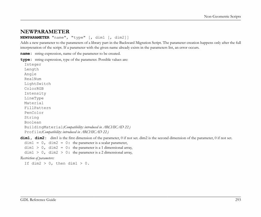
Non-Geometric Scripts
GDL Reference Guide 293
NEWPARAMETERNEWPARAMETER "name", "type" [, dim1 [, dim2]]Adds a new parameter to the parameters of a library part in the Backward Migration Script. The parameter creation happens only after the fullinterpretation of the script. If a parameter with the given name already exists in the parameters list, an error occurs.name: string expression, name of the parameter to be created.type: string expression, type of the parameter. Possible values are:IntegerLengthAngleRealNumLightSwitchColorRGBIntensityLineTypeMaterialFillPatternPenColorStringBooleanBuildingMaterial(Compatibility: introduced in ARCHICAD 22.)Profile(Compatibility: introduced in ARCHICAD 22.)
dim1, dim2: dim1 is the first dimension of the parameter, 0 if not set. dim2 is the second dimension of the parameter, 0 if not set.dim1 = 0, dim2 = 0: the parameter is a scalar parameter,dim1 > 0, dim2 = 0: the parameter is a 1 dimensional array,dim1 > 0, dim2 > 0: the parameter is a 2 dimensional array,
Restriction of parameters:If dim2 > 0, then dim1 > 0.

Expressions and Functions
GDL Reference Guide 294
EXPRESSIONS AND FUNCTIONSAll parameters of GDL shapes can be the result of calculations. For example, you can define that the height of the cylinder is five times theradius of the cylinder, or prior to defining a cube, you can move the coordinate system in each direction by half the size of the cube, in orderto have the initial origin in the center of the cube rather than in its lower left corner. To define these calculations, GDL offers a large numberof mathematical tools: expressions, operators and functions.
EXPRESSIONSYou can write compound expressions in GDL statements. Expressions can be of numerical and string type. They are constants, variables,parameters or function calls and any combination of these in operators. Round bracket pairs (( )) (precedence 1) are used to override the defaultprecedence of the operators.Simple type variables can be given numerical and string values, even in the same script, and can be used in numerical and string type expressionsrespectively. Operations resulting in strings CANNOT be used directly as macro names in macro calls, or as attribute names in material, fill,line type or style definitions. Variables given a string value will be treated as such and can be used wherever string values are required. If later inthe script the same variable is given a numerical value, it will be usable in numerical expressions only until it is given a string value again. Wherepossible, in the precompilation process the type of the expressions is checked.
DICTDICT variableName1[, variableName2...]Compatibility: introduced in ARCHICAD 23.GDL supports dictionaries. A variable is declared as a dictionary after the above declaration statement (and cannot be changed to array orsimple type or vice versa). Library part parameters can also be dictionaries, by selecting Dictionary type in the parameter list.After the DICT keyword there can be any number of variable names separated by commas. Each variable will contain hierarchical key andvalue pairs. A key of the dictionary can be referenced with dot notation. The full path of a key cannot be longer than 255 characters (countingarray indices as one character).Dictionaries and simple type values:• simple type (string, integer, floating-point) values can be assigned to dictionary keys,• no declaration is necessary, the value type for the key is set by the current value:
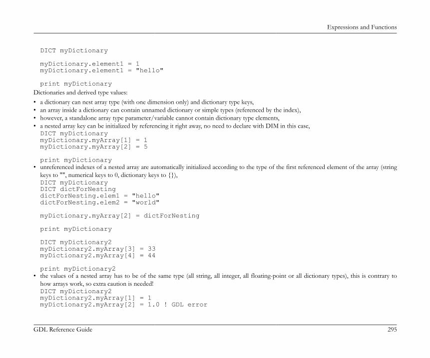
Expressions and Functions
GDL Reference Guide 295
DICT myDictionary
myDictionary.element1 = 1myDictionary.element1 = "hello"
print myDictionaryDictionaries and derived type values:• a dictionary can nest array type (with one dimension only) and dictionary type keys,• an array inside a dictionary can contain unnamed dictionary or simple types (referenced by the index),• however, a standalone array type parameter/variable cannot contain dictionary type elements,• a nested array key can be initialized by referencing it right away, no need to declare with DIM in this case,DICT myDictionarymyDictionary.myArray[1] = 1myDictionary.myArray[2] = 5
print myDictionary• unreferenced indexes of a nested array are automatically initialized according to the type of the first referenced element of the array (string
keys to "", numerical keys to 0, dictionary keys to {}),DICT myDictionaryDICT dictForNestingdictForNesting.elem1 = "hello"dictForNesting.elem2 = "world"
myDictionary.myArray[2] = dictForNesting
print myDictionary
DICT myDictionary2myDictionary2.myArray[3] = 33myDictionary2.myArray[4] = 44
print myDictionary2• the values of a nested array has to be of the same type (all string, all integer, all floating-point or all dictionary types), this is contrary to
how arrays work, so extra caution is needed!DICT myDictionary2myDictionary2.myArray[1] = 1myDictionary2.myArray[2] = 1.0 ! GDL error
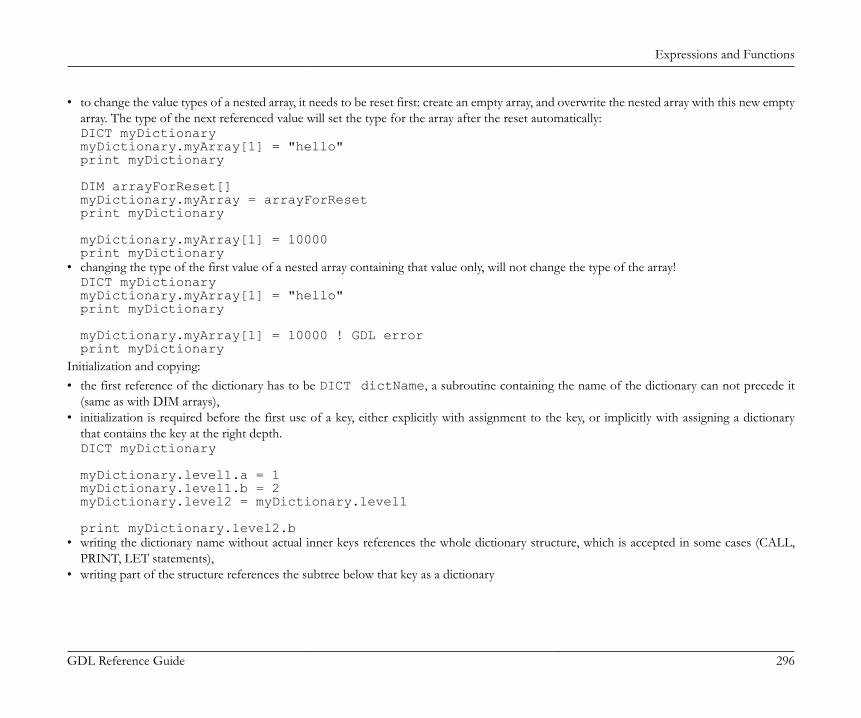
Expressions and Functions
GDL Reference Guide 296
• to change the value types of a nested array, it needs to be reset first: create an empty array, and overwrite the nested array with this new emptyarray. The type of the next referenced value will set the type for the array after the reset automatically:DICT myDictionarymyDictionary.myArray[1] = "hello"print myDictionary
DIM arrayForReset[]myDictionary.myArray = arrayForResetprint myDictionary
myDictionary.myArray[1] = 10000print myDictionary
• changing the type of the first value of a nested array containing that value only, will not change the type of the array!DICT myDictionarymyDictionary.myArray[1] = "hello"print myDictionary
myDictionary.myArray[1] = 10000 ! GDL errorprint myDictionary
Initialization and copying:• the first reference of the dictionary has to be DICT dictName, a subroutine containing the name of the dictionary can not precede it
(same as with DIM arrays),• initialization is required before the first use of a key, either explicitly with assignment to the key, or implicitly with assigning a dictionary
that contains the key at the right depth.DICT myDictionary
myDictionary.level1.a = 1myDictionary.level1.b = 2myDictionary.level2 = myDictionary.level1
print myDictionary.level2.b• writing the dictionary name without actual inner keys references the whole dictionary structure, which is accepted in some cases (CALL,
PRINT, LET statements),• writing part of the structure references the subtree below that key as a dictionary
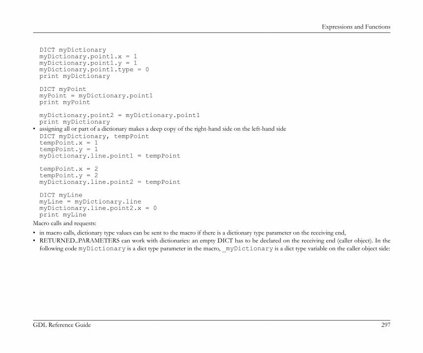
Expressions and Functions
GDL Reference Guide 297
DICT myDictionarymyDictionary.point1.x = 1myDictionary.point1.y = 1myDictionary.point1.type = 0print myDictionary
DICT myPointmyPoint = myDictionary.point1print myPoint
myDictionary.point2 = myDictionary.point1print myDictionary
• assigning all or part of a dictionary makes a deep copy of the right-hand side on the left-hand sideDICT myDictionary, tempPointtempPoint.x = 1tempPoint.y = 1myDictionary.line.point1 = tempPoint
tempPoint.x = 2tempPoint.y = 2myDictionary.line.point2 = tempPoint
DICT myLinemyLine = myDictionary.linemyDictionary.line.point2.x = 0print myLine
Macro calls and requests:• in macro calls, dictionary type values can be sent to the macro if there is a dictionary type parameter on the receiving end,• RETURNED_PARAMETERS can work with dictionaries: an empty DICT has to be declared on the receiving end (caller object). In the
following code myDictionary is a dict type parameter in the macro, _myDictionary is a dict type variable on the caller object side:

Expressions and Functions
GDL Reference Guide 298
! caller object Master scriptDICT _myDictionary
_myDictionary.element1 = 1_myDictionary.element2 = 2
DICT _dictForReceivedData
call "macroname" parameters all myDictionary = _myDictionary, returned_parameters _dictForReceivedData
print _dictForReceivedData
! in the macro object Master scriptmyDictionary.element1 = myDictionary.element1 * 2myDictionary.element2 = myDictionary.element2 * 2
end myDictionary• in REQUEST options currently there is no request supporting dictionaries. However, the possibility is open for the future.• LIBRARYGLOBAL requests cannot return dictionary type values.Visualization and functions:• dictionary type parameters are not visible on "All Parameters" page in the "Settings" dialog,• dictionary type parameters are not available for Listing display or IFC mappings,• text-like visualization works only with the PRINT command ("Check Script" warning and printed to Report window in JSON format),• general text handling commands like TEXT2, RICHTEXT2, etc. are not supporting the complete dictionary,• however, nested non-dictionary type values can be displayed with them,DICT myDictionarymyDictionary.myArray[1] = "hello"myDictionary.myArray[2] = "world"
text2 0, 0, myDictionary.myArray[1] + " " + myDictionary.myArray[2]print myDictionary
• values for a dictionary type parameter can only be set via the Parameter script (no direct user input is available through Parameter list or UIcontrols), the VALUES command is disabled for this type,
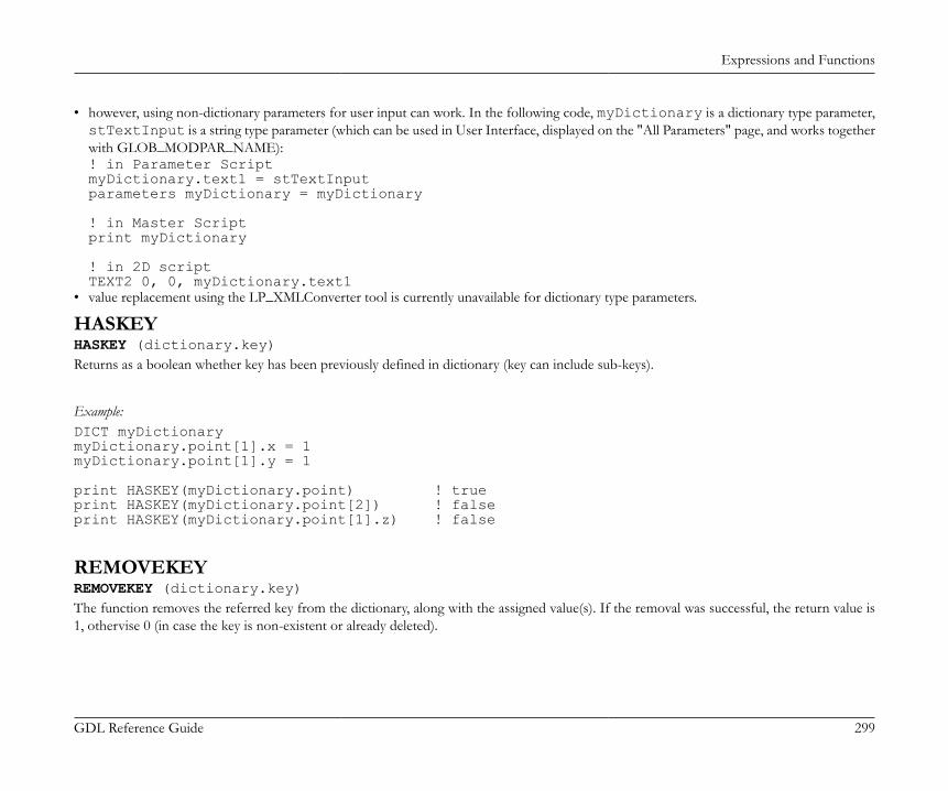
Expressions and Functions
GDL Reference Guide 299
• however, using non-dictionary parameters for user input can work. In the following code, myDictionary is a dictionary type parameter,stTextInput is a string type parameter (which can be used in User Interface, displayed on the "All Parameters" page, and works togetherwith GLOB_MODPAR_NAME):! in Parameter ScriptmyDictionary.text1 = stTextInputparameters myDictionary = myDictionary
! in Master Scriptprint myDictionary
! in 2D scriptTEXT2 0, 0, myDictionary.text1
• value replacement using the LP_XMLConverter tool is currently unavailable for dictionary type parameters.
HASKEYHASKEY (dictionary.key)Returns as a boolean whether key has been previously defined in dictionary (key can include sub-keys).
Example:DICT myDictionarymyDictionary.point[1].x = 1myDictionary.point[1].y = 1
print HASKEY(myDictionary.point) ! trueprint HASKEY(myDictionary.point[2]) ! falseprint HASKEY(myDictionary.point[1].z) ! false
REMOVEKEYREMOVEKEY (dictionary.key)The function removes the referred key from the dictionary, along with the assigned value(s). If the removal was successful, the return value is1, othervise 0 (in case the key is non-existent or already deleted).
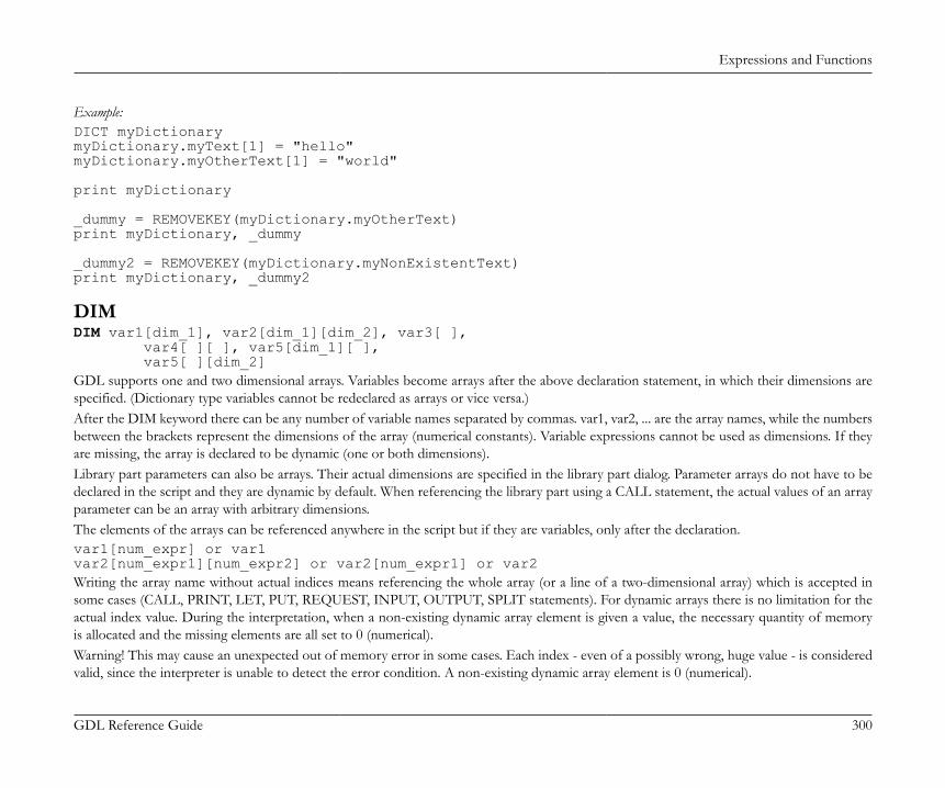
Expressions and Functions
GDL Reference Guide 300
Example:DICT myDictionarymyDictionary.myText[1] = "hello"myDictionary.myOtherText[1] = "world"
print myDictionary
_dummy = REMOVEKEY(myDictionary.myOtherText)print myDictionary, _dummy
_dummy2 = REMOVEKEY(myDictionary.myNonExistentText)print myDictionary, _dummy2
DIMDIM var1[dim_1], var2[dim_1][dim_2], var3[ ], var4[ ][ ], var5[dim_1][ ], var5[ ][dim_2]GDL supports one and two dimensional arrays. Variables become arrays after the above declaration statement, in which their dimensions arespecified. (Dictionary type variables cannot be redeclared as arrays or vice versa.)After the DIM keyword there can be any number of variable names separated by commas. var1, var2, ... are the array names, while the numbersbetween the brackets represent the dimensions of the array (numerical constants). Variable expressions cannot be used as dimensions. If theyare missing, the array is declared to be dynamic (one or both dimensions).Library part parameters can also be arrays. Their actual dimensions are specified in the library part dialog. Parameter arrays do not have to bedeclared in the script and they are dynamic by default. When referencing the library part using a CALL statement, the actual values of an arrayparameter can be an array with arbitrary dimensions.The elements of the arrays can be referenced anywhere in the script but if they are variables, only after the declaration.var1[num_expr] or var1var2[num_expr1][num_expr2] or var2[num_expr1] or var2Writing the array name without actual indices means referencing the whole array (or a line of a two-dimensional array) which is accepted insome cases (CALL, PRINT, LET, PUT, REQUEST, INPUT, OUTPUT, SPLIT statements). For dynamic arrays there is no limitation for theactual index value. During the interpretation, when a non-existing dynamic array element is given a value, the necessary quantity of memoryis allocated and the missing elements are all set to 0 (numerical).Warning! This may cause an unexpected out of memory error in some cases. Each index - even of a possibly wrong, huge value - is consideredvalid, since the interpreter is unable to detect the error condition. A non-existing dynamic array element is 0 (numerical).
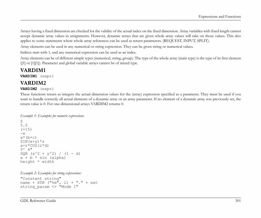
Expressions and Functions
GDL Reference Guide 301
Arrays having a fixed dimension are checked for the validity of the actual index on the fixed dimension. Array variables with fixed length cannotaccept dynamic array values in assignments. However, dynamic arrays that are given whole array values will take on those values. This alsoapplies to some statements where whole array references can be used as return parameters. (REQUEST, INPUT, SPLIT).Array elements can be used in any numerical or string expression. They can be given string or numerical values.Indices start with 1, and any numerical expression can be used as an index.Array elements can be of different simple types (numerical, string, group). The type of the whole array (main type) is the type of its first element([1] or [1][1]). Parameter and global variable arrays cannot be of mixed type.
VARDIM1VARDIM1 (expr)
VARDIM2VARDIM2 (expr)These functions return as integers the actual dimension values for the (array) expression specified as a parameter. They must be used if youwant to handle correctly all actual elements of a dynamic array or an array parameter. If no element of a dynamic array was previously set, thereturn value is 0. For one-dimensional arrays VARDIM2 returns 0.
Example 1: Examples for numeric expressions:Z5.5(+15)-xa*(b+c)SIN(x+y)*za+r*COS(i*d)5' 4"SQR (x^2 + y^2) / (1 - d)a + b * sin (alpha)height * width
Example 2: Examples for string expressions:"Constant string"name + STR ("%m", i) + "." + extstring_param <> "Mode 1"

Expressions and Functions
GDL Reference Guide 302
Example 3: Examples for expressions using array values:DIM tab[5], tab2[3][4] ! declarationtab[1] + tab[2]tab2[2][3] + APRINT tabDIM f1 [5], v1[], v2[][]v1[3] = 3 ! v1[1] = 0, v1[2] = 0, array of 3 elementsv2[2][3] = 23 ! all other elements(2 X 3) = 0PRINT v1, v2DIM f1 [5], v1[], v2[][]FOR i = 1 TO VARDIM1(f1) f1[i] = iNEXT iv1 = f1v2 [1] = f1PRINT v1, v2
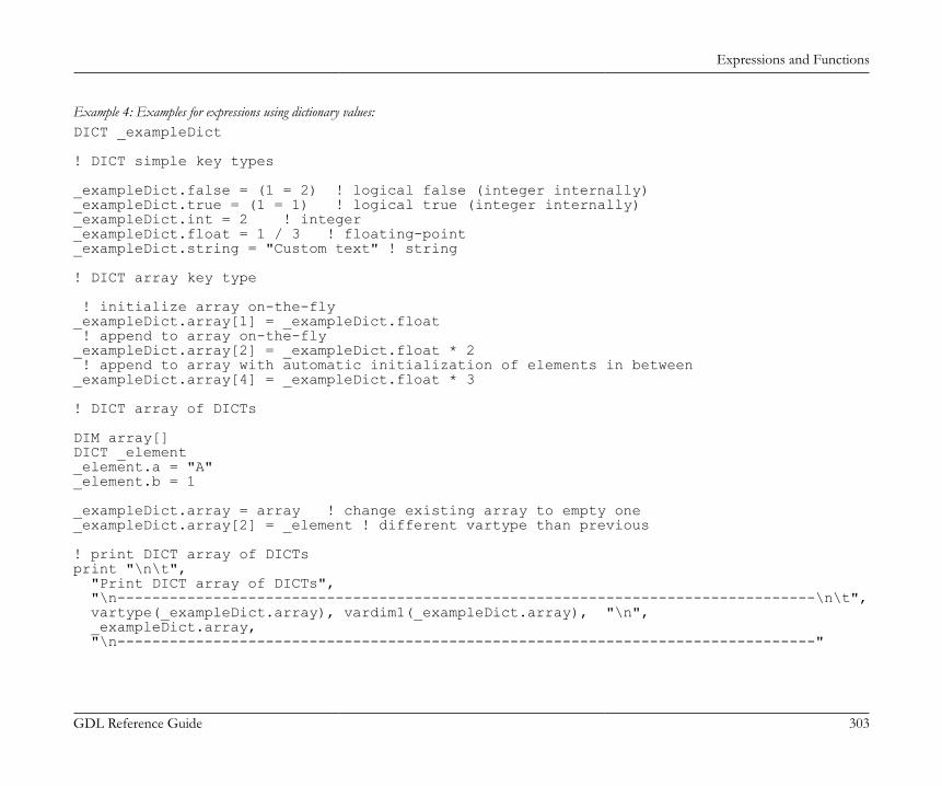
Expressions and Functions
GDL Reference Guide 303
Example 4: Examples for expressions using dictionary values:DICT _exampleDict
! DICT simple key types
_exampleDict.false = (1 = 2) ! logical false (integer internally)_exampleDict.true = (1 = 1) ! logical true (integer internally)_exampleDict.int = 2 ! integer_exampleDict.float = 1 / 3 ! floating-point_exampleDict.string = "Custom text" ! string
! DICT array key type
! initialize array on-the-fly_exampleDict.array[1] = _exampleDict.float ! append to array on-the-fly _exampleDict.array[2] = _exampleDict.float * 2 ! append to array with automatic initialization of elements in between_exampleDict.array[4] = _exampleDict.float * 3
! DICT array of DICTs
DIM array[]DICT _element_element.a = "A"_element.b = 1
_exampleDict.array = array ! change existing array to empty one_exampleDict.array[2] = _element ! different vartype than previous
! print DICT array of DICTsprint "\n\t", "Print DICT array of DICTs", "\n--------------------------------------------------------------------------------\n\t", vartype(_exampleDict.array), vardim1(_exampleDict.array), "\n", _exampleDict.array, "\n--------------------------------------------------------------------------------"

Expressions and Functions
GDL Reference Guide 304
PARVALUE_DESCRIPTION PARVALUE_DESCRIPTION (parname [, ind1 [, ind2]])This function returns the parameter value description string of a numerical parameter specified using the VALUES command statement. If nodescription is specified, the returned value is an empty string.parname: name of the parameterind1, ind2: actual indices if the parameter is an array.
OPERATORSThe operators below are listed in order of decreasing precedence. The evaluation of an expression begins with the highest precedence operatorand from left to right.
Arithmetical Operators
^ (or **) Power of precedence 2
* Multiplication precedence 3
/ Division precedence 3MOD (or %) Modulo (remainder of division) x MOD y = x - y * INT (x/y) precedence 3
+ Addition precedence 4
- Subtraction precedence 4
Note+ (addition) can also be applied to string expressions: the result is the concatenation of the strings. The result of the '/' (Division)is always a real number, while the result of the other operations depends on the type of the operands: if all operands are integer, theresult will be integer, otherwise real.

Expressions and Functions
GDL Reference Guide 305
Relational Operators
= Equal precedence 5
< Less than precedence 5
> Greater than precedence 5
<= Less than or equal precedence 5
>= Greater than or equal precedence 5
<> (or #) Not equal precedence 5
NoteThese operators can be used between any two string expressions also (string comparison is case sensitive). The result is an integer, 1or 0. There is not recommended to use the '=' (Equal), '<=' (Less than or equal), '>=' (Greater than or equal), '<>' (or #) (Not equal)operators with real operands, as these operations can result in precision problems.
Boolean Operators
AND (or &) Logical and precedence 6OR (or |) Logical inclusive or precedence 7EXOR (or @) Logical exclusive or precedence 8
NoteBoolean operators work with integer numbers. In consequence, 0 means false, while any other number means true. The value of alogical expression is also integer, i.e., 1 for true and 0 for false. It is not recommended to use boolean operators with real operands,as these operations can result in precision problems.

Expressions and Functions
GDL Reference Guide 306
FUNCTIONS
Arithmetical FunctionsABSABS (x)Returns the absolute value of x (integer if x integer, real otherwise).
CEILCEIL (x)Returns the smallest integral value that is not smaller than x (always integer). (e.g., CEIL(1.23) = 2; CEIL (-1.9) = -1).
INTINT (x)Returns the integral part of x (always integer). (e.g., INT(1.23) = 1, INT(-1.23) = -2).
FRAFRA (x)Returns the fractional part of x (integer 0 if x integer, real otherwise). (e.g., FRA(1.23) = 0.23, FRA(-1.23) = 0.77).
ROUND_INTROUND_INT (x)Returns the rounded integer part of x. The 'i = ROUND_INT (x)' expression is equivalent with the following script:IF x < 0.0 THEN i = INT (x - 0.5) ELSE i = INT (x + 0.5)
SGNSGN (x)Returns +1 integer if x positive, -1 integer if x negative, otherwise 0 integer.
SQRSQR (x)Returns the square root of x (always real).
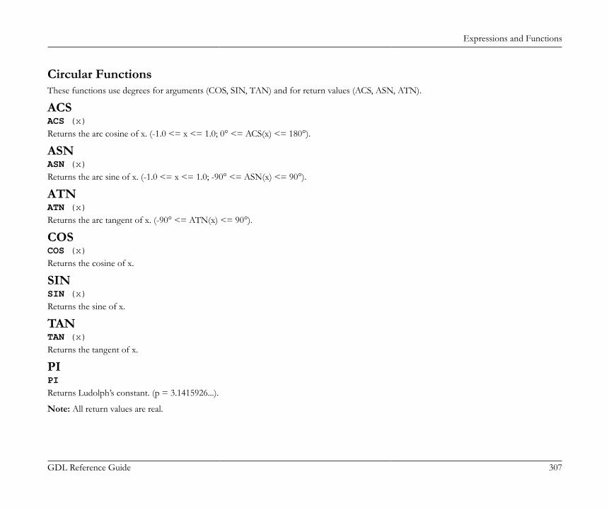
Expressions and Functions
GDL Reference Guide 307
Circular FunctionsThese functions use degrees for arguments (COS, SIN, TAN) and for return values (ACS, ASN, ATN).
ACSACS (x)Returns the arc cosine of x. (-1.0 <= x <= 1.0; 0° <= ACS(x) <= 180°).
ASNASN (x)Returns the arc sine of x. (-1.0 <= x <= 1.0; -90° <= ASN(x) <= 90°).
ATNATN (x)Returns the arc tangent of x. (-90° <= ATN(x) <= 90°).
COSCOS (x)Returns the cosine of x.
SINSIN (x)Returns the sine of x.
TANTAN (x)Returns the tangent of x.
PIPIReturns Ludolph’s constant. (p = 3.1415926...).
Note: All return values are real.
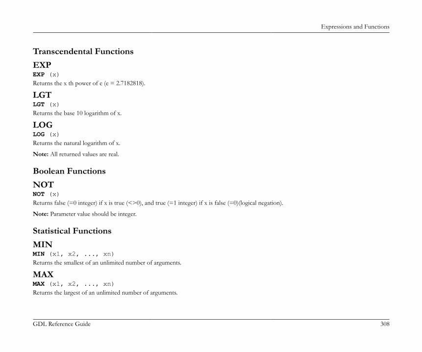
Expressions and Functions
GDL Reference Guide 308
Transcendental FunctionsEXPEXP (x)Returns the x th power of e (e = 2.7182818).
LGTLGT (x)Returns the base 10 logarithm of x.
LOGLOG (x)Returns the natural logarithm of x.
Note: All returned values are real.
Boolean FunctionsNOTNOT (x)Returns false (=0 integer) if x is true (<>0), and true (=1 integer) if x is false (=0)(logical negation).
Note: Parameter value should be integer.
Statistical FunctionsMINMIN (x1, x2, ..., xn)Returns the smallest of an unlimited number of arguments.
MAXMAX (x1, x2, ..., xn)Returns the largest of an unlimited number of arguments.
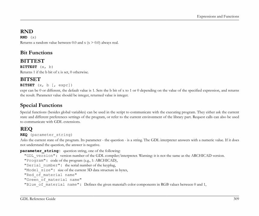
Expressions and Functions
GDL Reference Guide 309
RNDRND (x)Returns a random value between 0.0 and x (x > 0.0) always real.
Bit FunctionsBITTESTBITTEST (x, b)Returns 1 if the b bit of x is set, 0 otherwise.
BITSETBITSET (x, b [, expr])expr can be 0 or different, the default value is 1. Sets the b bit of x to 1 or 0 depending on the value of the specified expression, and returnsthe result. Parameter value should be integer, returned value is integer.
Special FunctionsSpecial functions (besides global variables) can be used in the script to communicate with the executing program. They either ask the currentstate and different preferences settings of the program, or refer to the current environment of the library part. Request calls can also be usedto communicate with GDL extensions.
REQREQ (parameter_string)Asks the current state of the program. Its parameter - the question - is a string. The GDL interpreter answers with a numeric value. If it doesnot understand the question, the answer is negative.parameter_string: question string, one of the following:"GDL_version": version number of the GDL compiler/interpreter. Warning: it is not the same as the ARCHICAD version."Program": code of the program (e.g., 1: ARCHICAD),"Serial_number": the serial number of the keyplug,"Model_size": size of the current 3D data structure in bytes,"Red_of_material name""Green_of_material name""Blue_of_material name": Defines the given material’s color components in RGB values between 0 and 1,

Expressions and Functions
GDL Reference Guide 310
"Red_of_pen index""Green_of_pen index""Blue_of_pen index": Defines the given pen’s color components in RGB values between 0 and 1,"Pen_of_RGB r g b": Defines the index of the pen closest to the given color. The r, g and b constants’ values are between 0 and 1.
REQUESTREQUEST (question_name, name | index, variable1 [, variable2, ...])The first parameter represents the question string while the second represents the object of the question (if it exists) and can be of either stringor numeric type (for example, the question can be "Rgb_of_material" and its object the material’s name, or "Rgb_of_pen" and its object theindex of the pen). The other parameters are variable names in which the return values (the answers) are stored.The return value of the requests is always the number of successfully retrieved values (integer), while the type of the retrieved values is definedby each request in part. In the case of a badly formulated question or a nonexistent name, the return value will be 0.ARCHICAD identifies the order and number of the input parameters by either the version of the command, or the exact name (as stringconstant) of the request option. Current accepted variations:• n = REQUEST - default request, with 1 input parameter of string or numeric type• n = REQUEST{2} - 2 input parameters: string or numeric, string type• n = REQUEST{3} - 2 input parameters: string, string or numeric array type• n = REQUEST{4} - 3 input parameters: string or numeric, numeric, string type. Compatibility: introduced in ARCHICAD 21.For the list of available options see the section called “REQUEST Options”.
INDIND (MATERIAL, name_string)IND (BUILDING_MATERIAL, name_string)IND (FILL, name_string)IND (LINE_TYPE, name_string)IND (STYLE, name_string)IND (TEXTURE, name_string)IND (PROFILE_ATTR, name_string, index)This function returns the current index of the material, building material, fill, line type or style, texture or profile attribute. The main use of theresulting number is to transfer it to a macro that requires the same attribute as the calling macro.The functions return an attribute index (integer) value. The result is negative for inline definitions (inside the script or from Master_GDL file)and positive for global definitions (from the project attributes).See also the section called “Inline Attribute Definition”.
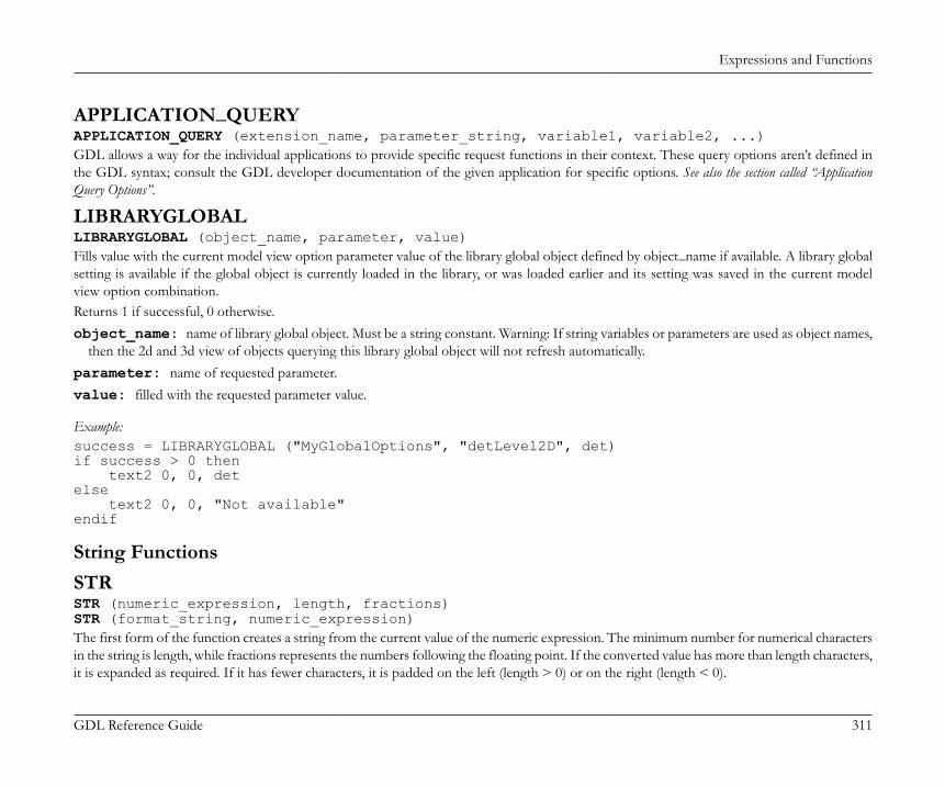
Expressions and Functions
GDL Reference Guide 311
APPLICATION_QUERYAPPLICATION_QUERY (extension_name, parameter_string, variable1, variable2, ...)GDL allows a way for the individual applications to provide specific request functions in their context. These query options aren’t defined inthe GDL syntax; consult the GDL developer documentation of the given application for specific options. See also the section called “ApplicationQuery Options”.
LIBRARYGLOBALLIBRARYGLOBAL (object_name, parameter, value)Fills value with the current model view option parameter value of the library global object defined by object_name if available. A library globalsetting is available if the global object is currently loaded in the library, or was loaded earlier and its setting was saved in the current modelview option combination.Returns 1 if successful, 0 otherwise.object_name: name of library global object. Must be a string constant. Warning: If string variables or parameters are used as object names,
then the 2d and 3d view of objects querying this library global object will not refresh automatically.parameter: name of requested parameter.value: filled with the requested parameter value.
Example:success = LIBRARYGLOBAL ("MyGlobalOptions", "detLevel2D", det)if success > 0 then text2 0, 0, detelse text2 0, 0, "Not available"endif
String FunctionsSTRSTR (numeric_expression, length, fractions)STR (format_string, numeric_expression)The first form of the function creates a string from the current value of the numeric expression. The minimum number for numerical charactersin the string is length, while fractions represents the numbers following the floating point. If the converted value has more than length characters,it is expanded as required. If it has fewer characters, it is padded on the left (length > 0) or on the right (length < 0).

Expressions and Functions
GDL Reference Guide 312
In the second form, the format_string can either be a variable or a constant. If the format is empty, it is interpreted as meters, with an accuracyof three decimals (displaying 0s).Restriction of parameters:length >= -100, length <= 100fractions <= 20, fractions < length
Example:a=4.5b=2.345TEXT2 0, 2, STR(a, 8, 2) ! 4.50TEXT2 0, 1, STR(b, 8, 2) ! 2.34TEXT2 0, 0, STR(a*b, 8, 2) ! 10.55
STR{2}STR{2} (format_string, numeric_expression [, extra_accuracy_string])Extension of the second form of STR. If the extra accuracy flags are set in the format_string, the STR{2} function will return the correspondingextra accuracy string in the 3rd parameter.format_string: "%[0 or more flags][field_width][.precision] conv_spec"flags: (for m, mm, cm, dm, e, df, di, sqm, sqcm, sqf, sqi, dd, gr, rad, cum, l, cucm, cumm, cuf, cui, cuy, gal):(none): right justify (default),-: left justify,+: explicit plus sign,(space): in place of a + sign,'*0': extra accuracy Off (default),'*1': extra accuracy .5,'*2': extra accuracy .25,'*3': extra accuracy .1,'*4': extra accuracy .01,'*5': rounding to .5 within displayed decimal range, no returned extra accuracy string, (used for area calculations),'*6': rounding to .25 within displayed decimal range, no returned extra accuracy string, (used for area calculations),'*7': fills the fractional part of numeric_expression into the extra_accuracy_string in case of fi or ffi, while the returned expression ofthe function does not contain the fractional parts,'#': don’t display 0s (for m, mm, cm, dm, ffi, fdi, fi, df, di, sqm, sqcm, sqf, sqi, dd, fr, rad, cum, l, cucm, cumm, cuf, cui, cuy, gal),'0': display 0 inches (for ffi, fdi, fi),
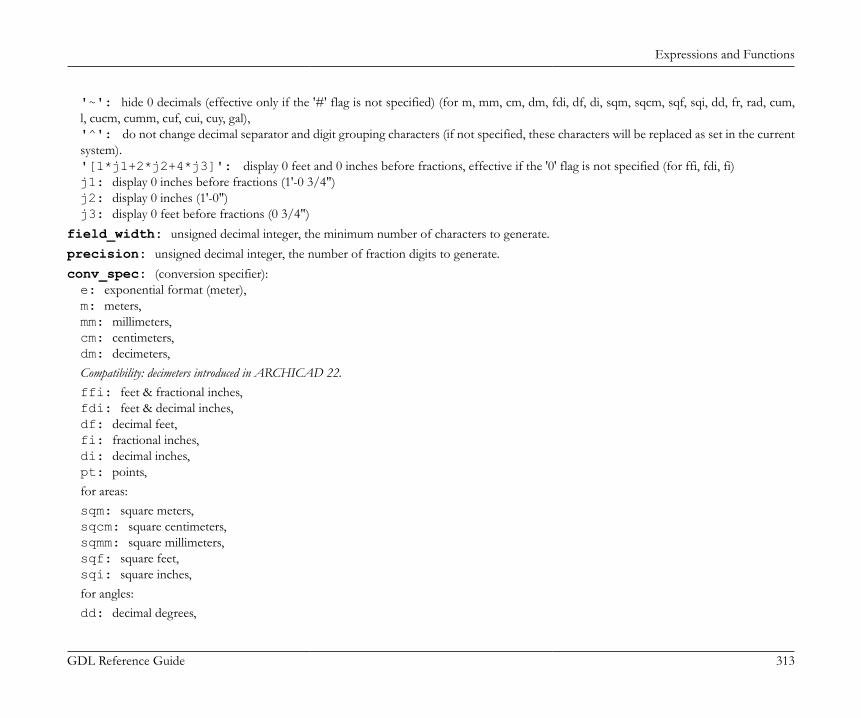
Expressions and Functions
GDL Reference Guide 313
'~': hide 0 decimals (effective only if the '#' flag is not specified) (for m, mm, cm, dm, fdi, df, di, sqm, sqcm, sqf, sqi, dd, fr, rad, cum,l, cucm, cumm, cuf, cui, cuy, gal),'^': do not change decimal separator and digit grouping characters (if not specified, these characters will be replaced as set in the currentsystem).'[1*j1+2*j2+4*j3]': display 0 feet and 0 inches before fractions, effective if the '0' flag is not specified (for ffi, fdi, fi)j1: display 0 inches before fractions (1'-0 3/4")j2: display 0 inches (1'-0")j3: display 0 feet before fractions (0 3/4")
field_width: unsigned decimal integer, the minimum number of characters to generate.precision: unsigned decimal integer, the number of fraction digits to generate.conv_spec: (conversion specifier):e: exponential format (meter),m: meters,mm: millimeters,cm: centimeters,dm: decimeters,Compatibility: decimeters introduced in ARCHICAD 22.ffi: feet & fractional inches,fdi: feet & decimal inches,df: decimal feet,fi: fractional inches,di: decimal inches,pt: points,for areas:sqm: square meters,sqcm: square centimeters,sqmm: square millimeters,sqf: square feet,sqi: square inches,for angles:dd: decimal degrees,

Expressions and Functions
GDL Reference Guide 314
dms: degrees, minutes, seconds,gr: grads,rad: radians,surv: surveyors unit,for volumes:cum: cubic meters,l: liters,cucm: cubic centimeters,cumm: cubic millimeters,cuf: cubic feet,cui: cubic inches,cuy: cubic yards,gal: gallons.
Example:nr = 0.345678TEXT2 0, 23, STR ("%m", nr) !0.346TEXT2 0, 22, STR ("%#10.2m", nr) !35TEXT2 0, 21, STR ("%.4cm", nr) !34.5678TEXT2 0, 20, STR ("%12.4cm", nr) ! 34.5678TEXT2 0, 19, STR ("%.6mm", nr) !345.678000TEXT2 0, 18, STR ("%+15e", nr) !+3.456780e-01TEXT2 0, 17, STR ("%ffi", nr) !1'-2"TEXT2 0, 16, STR ("%0.16ffi", nr) !1'-1 5/8"TEXT2 0, 15, STR ("% .3fdi", nr) ! 1'-1.609"TEXT2 0, 14, STR ("% -10.4df", nr) ! 1.1341'TEXT2 0, 13, STR ("%0.64fi", nr) !13 39/64"TEXT2 0, 12, STR ("%+12.4di", nr)!+13.6094"TEXT2 0, 11, STR ("%#.3sqm", nr) !346TEXT2 0, 10, STR ("%+sqcm", nr) !+3,456.78TEXT2 0, 9, STR ("% .2sqmm", nr)! 345,678.00TEXT2 0, 8, STR ("%-12sqf", nr) !3.72TEXT2 0, 7, STR ("%10sqi", nr) ! 535.80TEXT2 0, 6, STR ("%.2pt", nr) !0.35

Expressions and Functions
GDL Reference Guide 315
alpha = 88.657TEXT2 0, 5, STR ("%+10.3dd", alpha) !+88.657°TEXT2 0, 4, STR ("%.1dms", alpha) !88°39'TEXT2 0, 3, STR ("%.2dms", alpha) !88°39'25"TEXT2 0, 2, STR ("%10.4gr", alpha) ! 98.5078GTEXT2 0, 1, STR ("%rad", alpha) !1.55RTEXT2 0, 0, STR ("%.2surv", alpha) !N 1°20'35" E
nr = 1'-0 3/4"TEXT2 0, -1, STR ("%[1].16ffi", nr) !1'-0 3/4"nr = 1'-0"TEXT2 0, -2, STR ("%[5].16ffi", nr) !1'nr = 0 3/4"TEXT2 0, -3, STR ("%#[7].16ffi", nr) !0 3/4"
nr = 0.34278TEXT2 0, 0, STR ("%*5 .4m", nr) !0.3430
! split to integral and fractional partsextra_accuracy_string = ""nr = 1'-0 3/4"
TEXT2 0, -3, STR{2}("%*7.16ffi", nr, extra_accuracy_string) !1'-TEXT2 0, -4, extra_accuracy_string !3/4"
SPLITSPLIT (string, format, variable1 [, variable2, ..., variablen])Splits the string parameter according to the format in one or more numeric or string parts. The split process stops when the first non-matchingpart is encountered. Returns the number of successfully read values (integer).string: the string to be split.format: any combination of constant strings, %s, %n and %^n -s. Parts in the string must fit the constant strings, %s denotes any string
value delimited by spaces or tabs, while %n or %^n denotes any numeric value. If the '^' flag is present, current system settings for decimalseparator and digit grouping characters are taken into consideration when matching the actual numerical value.
variablei: names of the variables to store the split string parts.

Expressions and Functions
GDL Reference Guide 316
Example:ss = "3 pieces 2x5 beam"n = SPLIT (ss, "%n pieces %nx%n %s", num, ss1, size1, ss2, size2, name)IF n = 6 THEN PRINT num, ss1, size1, ss2, size2, name ! 3 pieces 2 x 5 beamELSE PRINT "ERROR"ENDIF
STWSTW (string_expression)Returns the (real) width of the string in millimeters displayed in the current style. The width in meters, at current scale, is STW(string_expression) / 1000 * GLOB_SCALE.
Example:
DEFINE STYLE "own" "Gabriola", 180000 / GLOB_SCALE, 1, 0SET STYLE "own"string = "abcd"width = STW (string) / 1000 * GLOB_SCALEn = REQUEST ("Height_of_style", "own", height)height = height / 1000 * GLOB_SCALETEXT2 0,0, stringRECT2 0,0, width, -height
STRLENSTRLEN (string_expression)Returns the (integer) length of the string (the number of characters)

Expressions and Functions
GDL Reference Guide 317
STRSTRSTRSTR (string_expression1, string_expression2[, case_insensitivity])Returns the (integer) position of the first appearance of the second string in the first string. If the first string doesn’t contain the second one,the function returns 0.Note: In case string_expression2 is an empty string, the function returns 1.case_insensitivity:0 or not set: Case sensitive1: Case insensitive
Example 1:szFormat = ""n = REQUEST ("Linear_dimension", "", szFormat)unit = ""IF STRSTR (szFormat, "m") > 0 THEN unit = "m"IF STRSTR (szFormat, "mm") > 0 THEN unit = "mm"IF STRSTR (szFormat, "cm") > 0 THEN unit = "cm"IF STRSTR (szFormat, "dm") > 0 THEN unit = "dm"TEXT2 0, 0, STR (szFormat, a) + " " + unit !1.00 m
Example 2:STRSTR ("abcdefg", "BCdEf") = 0STRSTR ("abcdefg", "BCdEf", 0) = 0STRSTR ("abcdefg", "BCdEf", 1) = 2
STRSUBSTRSUB (string_expression, start_position, characters_number)Returns a substring of the string parameter that begins at the position given by the start_position parameter and its length is characters_numbercharacters.
Example:string = "Flowers.jpeg"len = STRLEN (string)iDotPos = STRSTR (string, ".")TEXT2 0, -1, STRSUB (string, 1, iDotPos - 1) !FlowersTEXT2 0, -2, STRSUB (string, len - 4, 5) !.jpeg
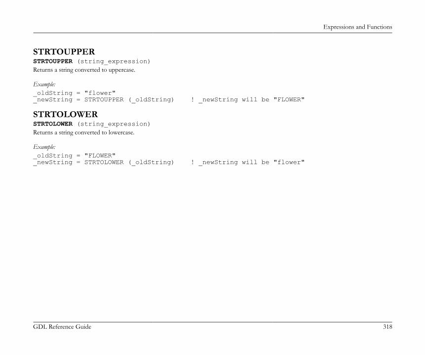
Expressions and Functions
GDL Reference Guide 318
STRTOUPPERSTRTOUPPER (string_expression)Returns a string converted to uppercase.
Example:_oldString = "flower"_newString = STRTOUPPER (_oldString) ! _newString will be "FLOWER"
STRTOLOWERSTRTOLOWER (string_expression)Returns a string converted to lowercase.
Example:_oldString = "FLOWER"_newString = STRTOLOWER (_oldString) ! _newString will be "flower"
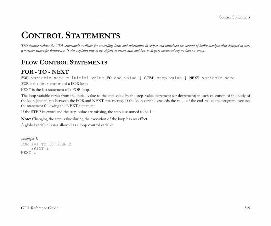
Control Statements
GDL Reference Guide 319
CONTROL STATEMENTSThis chapter reviews the GDL commands available for controlling loops and subroutines in scripts and introduces the concept of buffer manipulation designed to storeparameter values for further use. It also explains how to use objects as macro calls and how to display calculated expressions on screen.
FLOW CONTROL STATEMENTS
FOR - TO - NEXTFOR variable_name = initial_value TO end_value [ STEP step_value ] NEXT variable_nameFOR is the first statement of a FOR loop.NEXT is the last statement of a FOR loop.The loop variable varies from the initial_value to the end_value by the step_value increment (or decrement) in each execution of the body ofthe loop (statements between the FOR and NEXT statements). If the loop variable exceeds the value of the end_value, the program executesthe statement following the NEXT statement.If the STEP keyword and the step_value are missing, the step is assumed to be 1.
Note: Changing the step_value during the execution of the loop has no effect.A global variable is not allowed as a loop control variable.
Example 1:FOR i=1 TO 10 STEP 2 PRINT iNEXT i
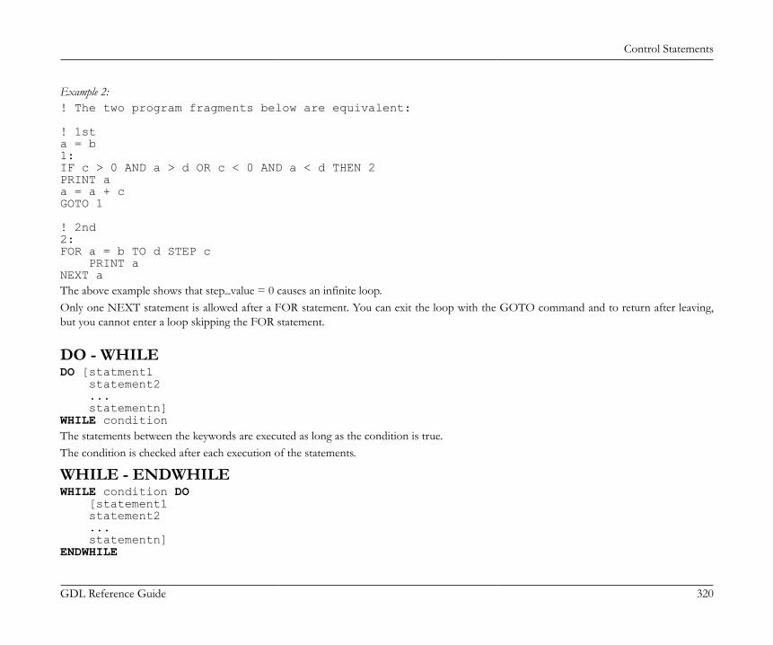
Control Statements
GDL Reference Guide 320
Example 2:! The two program fragments below are equivalent:
! 1sta = b1:IF c > 0 AND a > d OR c < 0 AND a < d THEN 2PRINT aa = a + cGOTO 1
! 2nd2:FOR a = b TO d STEP c PRINT aNEXT aThe above example shows that step_value = 0 causes an infinite loop.Only one NEXT statement is allowed after a FOR statement. You can exit the loop with the GOTO command and to return after leaving,but you cannot enter a loop skipping the FOR statement.
DO - WHILEDO [statment1 statement2 ... statementn]WHILE conditionThe statements between the keywords are executed as long as the condition is true.The condition is checked after each execution of the statements.
WHILE - ENDWHILEWHILE condition DO [statement1 statement2 ... statementn]ENDWHILE
Control Statements
GDL Reference Guide 321
The statements between the keywords are executed as long as the condition is true.The condition is checked before each execution of the statements.
REPEAT - UNTILREPEAT [statement1 statement2 ... statementn]UNTIL conditionThe statements between the keywords are executed until the condition becomes true.The condition is checked after each execution of the statements.

Control Statements
GDL Reference Guide 322
Example: The following four sequences of GDL commands are equivalent! 1stFOR i = 1 TO 5 STEP 1 BRICK 0.5, 0.5, 0.1 ADDZ 0.3NEXT i
! 2ndi = 1DO BRICK 0.5, 0.5, 0.1 ADDZ 0.3 i = i + 1WHILE i <= 5
! 3rdi = 1WHILE i <= 5 DO BRICK 0.5, 0.5, 0.1 ADDZ 0.3 i = i + 1ENDWHILE
! 4thi = 1REPEAT BRICK 0.5, 0.5, 0.1 ADDZ 0.3 i = i + 1UNTIL i > 5
IF - GOTOIF condition THEN labelIF condition GOTO labelIF condition GOSUB labelConditional jump statement. If the value of the condition expression is 0 (logical 'false'), the command has no effect, otherwise executioncontinues at the label. THEN, GOTO or THEN GOTO are equivalent in this context.

Control Statements
GDL Reference Guide 323
Example:IF a THEN 28IF i > j GOTO 200+i*jIF i > 0 GOSUB 9000
IF - THEN - ELSE - ENDIFIF condition THEN statement [ELSE statement]IF condition THEN [statement1 statement2 ... statementn][ELSE statementn+1 statementn+2 ... statementn+m]ENDIFIf you write only one command after keywords THEN and/or ELSE in the same row, there is no need for ENDIF. A command after THENor ELSE in the same row means a definite ENDIF.If there is a new row after THEN, the successive commands (all of them until the keyword ELSE or ENDIF) will only be executed if theexpression in the condition is true (other than zero). Otherwise, the commands following ELSE will be carried out. If the ELSE keyword isabsent, the commands after ENDIF will be carried out.

Control Statements
GDL Reference Guide 324
Example:IF a = b THEN height = 5 ELSE height = 7IF needDoors THEN CALL "door_macro" PARAMETERS ADDX aENDIFIF simple THEN HOTSPOT2 0, 0 RECT2 a, 0, 0, bELSE PROJECT2 3, 270, 1IF name = "Sphere" THEN ADDY b SPHERE 1ELSE ROTX 90 TEXT 0.002, 0, nameENDIF
GOTOGOTO labelUnconditional jump statement. The program executes a branch to the statement denoted by the value of the label (numerical or string). Variablelabel expressions can slow down interpretation due to runtime jumping address determination.
Example:GOTO K+2
GOSUBGOSUB labelInternal subroutine call where the label is the entry point of the subroutine. Label value can be any numerical or string expression. Variablelabel expressions can slow down interpretation due to runtime jumping address determination.
RETURNRETURNReturn from an internal subroutine.
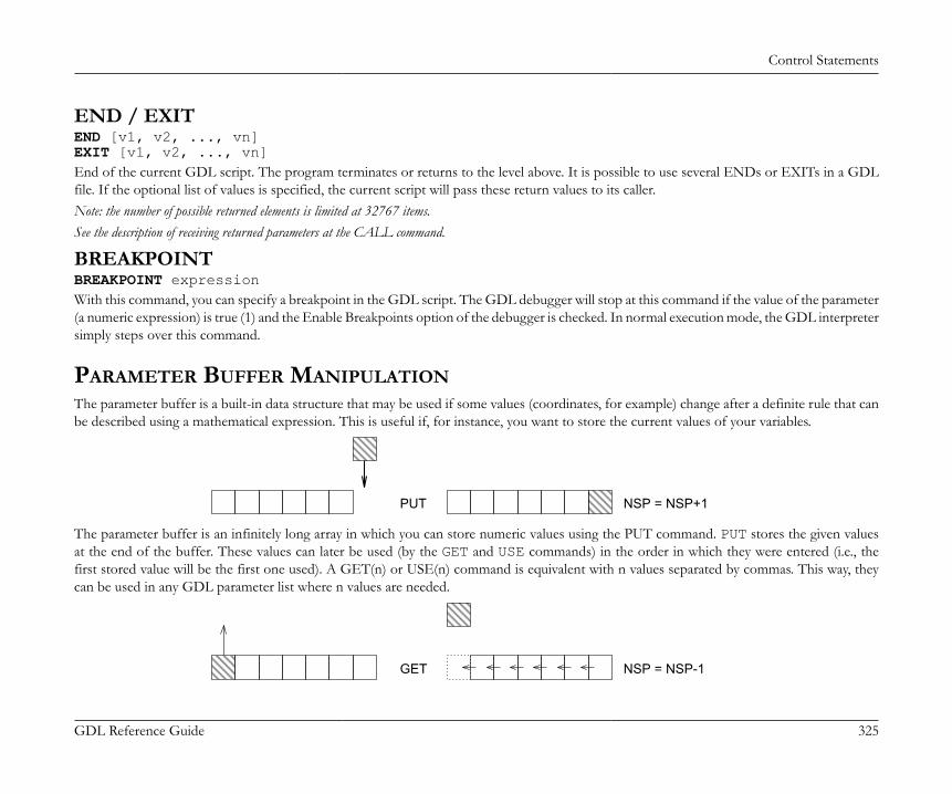
Control Statements
GDL Reference Guide 325
END / EXITEND [v1, v2, ..., vn]EXIT [v1, v2, ..., vn]End of the current GDL script. The program terminates or returns to the level above. It is possible to use several ENDs or EXITs in a GDLfile. If the optional list of values is specified, the current script will pass these return values to its caller.Note: the number of possible returned elements is limited at 32767 items.See the description of receiving returned parameters at the CALL command.
BREAKPOINTBREAKPOINT expressionWith this command, you can specify a breakpoint in the GDL script. The GDL debugger will stop at this command if the value of the parameter(a numeric expression) is true (1) and the Enable Breakpoints option of the debugger is checked. In normal execution mode, the GDL interpretersimply steps over this command.
PARAMETER BUFFER MANIPULATIONThe parameter buffer is a built-in data structure that may be used if some values (coordinates, for example) change after a definite rule that canbe described using a mathematical expression. This is useful if, for instance, you want to store the current values of your variables.
PUT NSP = NSP+1
The parameter buffer is an infinitely long array in which you can store numeric values using the PUT command. PUT stores the given valuesat the end of the buffer. These values can later be used (by the GET and USE commands) in the order in which they were entered (i.e., thefirst stored value will be the first one used). A GET(n) or USE(n) command is equivalent with n values separated by commas. This way, theycan be used in any GDL parameter list where n values are needed.
GET NSP = NSP-1

Control Statements
GDL Reference Guide 326
USE NSP = NSP
PUTPUT expression [, expression, ...]Store the given values in the given order in the internal parameter buffer.
GETGET (n)Use the next n values from the internal parameter buffer and then disregard them.
USEUSE (n)Use the next n values from the internal parameter buffer without deleting them. Following USE and GET functions can use the same parametersequence.
NSPNSPReturns the number of stored parameters in the internal buffer.
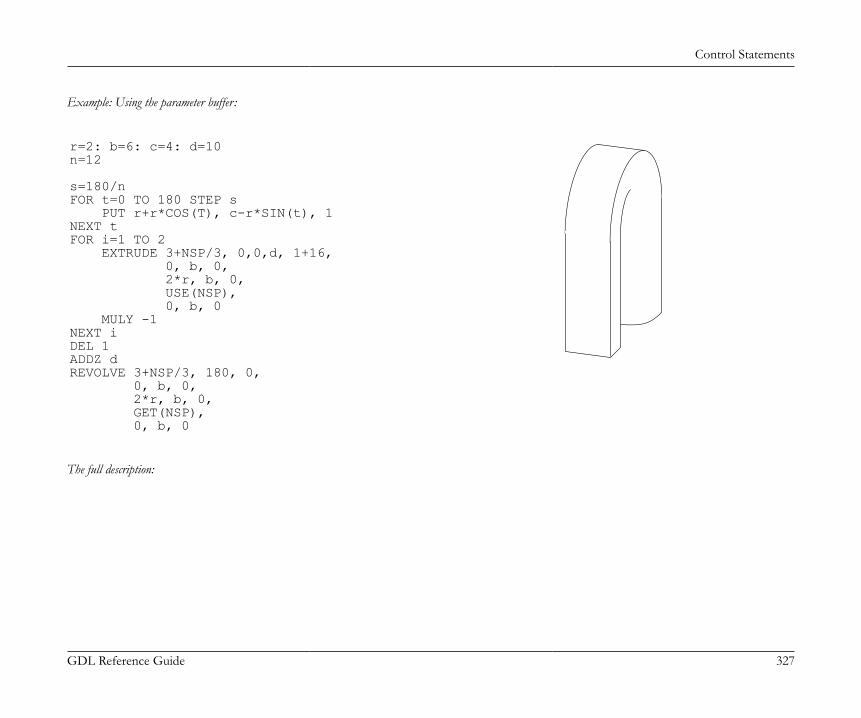
Control Statements
GDL Reference Guide 327
Example: Using the parameter buffer:
r=2: b=6: c=4: d=10n=12
s=180/nFOR t=0 TO 180 STEP s PUT r+r*COS(T), c-r*SIN(t), 1NEXT tFOR i=1 TO 2 EXTRUDE 3+NSP/3, 0,0,d, 1+16, 0, b, 0, 2*r, b, 0, USE(NSP), 0, b, 0 MULY -1NEXT iDEL 1ADDZ dREVOLVE 3+NSP/3, 180, 0, 0, b, 0, 2*r, b, 0, GET(NSP), 0, b, 0
The full description:
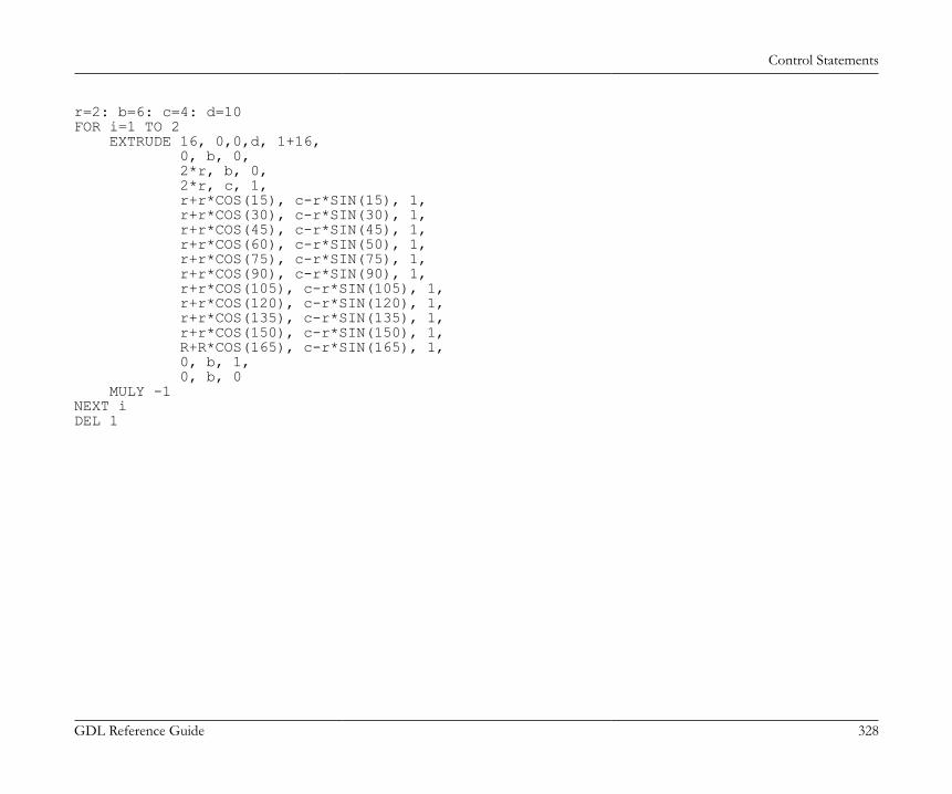
Control Statements
GDL Reference Guide 328
r=2: b=6: c=4: d=10FOR i=1 TO 2 EXTRUDE 16, 0,0,d, 1+16, 0, b, 0, 2*r, b, 0, 2*r, c, 1, r+r*COS(15), c-r*SIN(15), 1, r+r*COS(30), c-r*SIN(30), 1, r+r*COS(45), c-r*SIN(45), 1, r+r*COS(60), c-r*SIN(50), 1, r+r*COS(75), c-r*SIN(75), 1, r+r*COS(90), c-r*SIN(90), 1, r+r*COS(105), c-r*SIN(105), 1, r+r*COS(120), c-r*SIN(120), 1, r+r*COS(135), c-r*SIN(135), 1, r+r*COS(150), c-r*SIN(150), 1, R+R*COS(165), c-r*SIN(165), 1, 0, b, 1, 0, b, 0 MULY -1NEXT iDEL 1
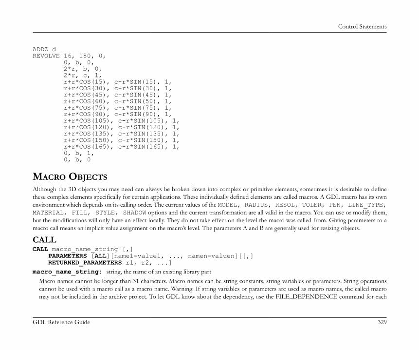
Control Statements
GDL Reference Guide 329
ADDZ dREVOLVE 16, 180, 0, 0, b, 0, 2*r, b, 0, 2*r, c, 1, r+r*COS(15), c-r*SIN(15), 1, r+r*COS(30), c-r*SIN(30), 1, r+r*COS(45), c-r*SIN(45), 1, r+r*COS(60), c-r*SIN(50), 1, r+r*COS(75), c-r*SIN(75), 1, r+r*COS(90), c-r*SIN(90), 1, r+r*COS(105), c-r*SIN(105), 1, r+r*COS(120), c-r*SIN(120), 1, r+r*COS(135), c-r*SIN(135), 1, r+r*COS(150), c-r*SIN(150), 1, r+r*COS(165), c-r*SIN(165), 1, 0, b, 1, 0, b, 0
MACRO OBJECTSAlthough the 3D objects you may need can always be broken down into complex or primitive elements, sometimes it is desirable to definethese complex elements specifically for certain applications. These individually defined elements are called macros. A GDL macro has its ownenvironment which depends on its calling order. The current values of the MODEL, RADIUS, RESOL, TOLER, PEN, LINE_TYPE,MATERIAL, FILL, STYLE, SHADOW options and the current transformation are all valid in the macro. You can use or modify them,but the modifications will only have an effect locally. They do not take effect on the level the macro was called from. Giving parameters to amacro call means an implicit value assignment on the macro’s level. The parameters A and B are generally used for resizing objects.
CALLCALL macro_name_string [,] PARAMETERS [ALL][name1=value1, ..., namen=valuen][[,] RETURNED_PARAMETERS r1, r2, ...]macro_name_string: string, the name of an existing library part
Macro names cannot be longer than 31 characters. Macro names can be string constants, string variables or parameters. String operationscannot be used with a macro call as a macro name. Warning: If string variables or parameters are used as macro names, the called macromay not be included in the archive project. To let GDL know about the dependency, use the FILE_DEPENDENCE command for each
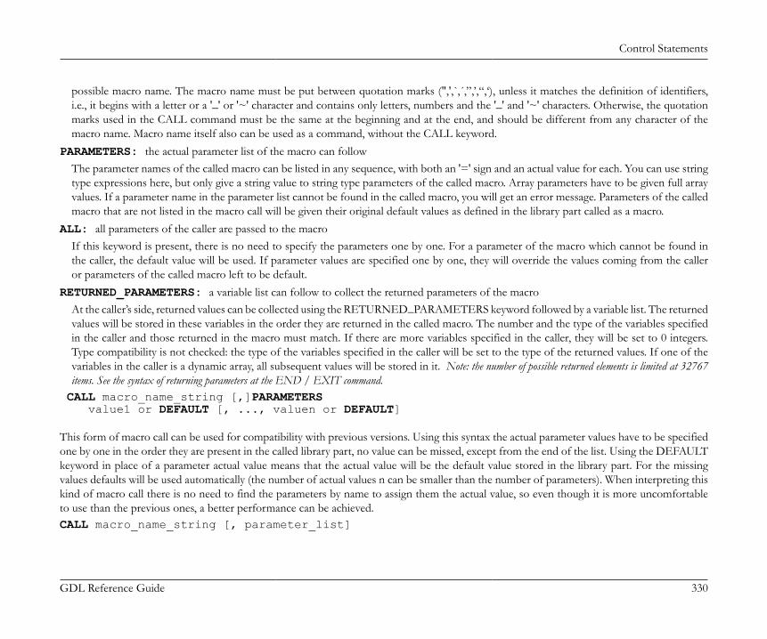
Control Statements
GDL Reference Guide 330
possible macro name. The macro name must be put between quotation marks (",',`,´,”,’,“,‘), unless it matches the definition of identifiers,i.e., it begins with a letter or a '_' or '~' character and contains only letters, numbers and the '_' and '~' characters. Otherwise, the quotationmarks used in the CALL command must be the same at the beginning and at the end, and should be different from any character of themacro name. Macro name itself also can be used as a command, without the CALL keyword.
PARAMETERS: the actual parameter list of the macro can followThe parameter names of the called macro can be listed in any sequence, with both an '=' sign and an actual value for each. You can use stringtype expressions here, but only give a string value to string type parameters of the called macro. Array parameters have to be given full arrayvalues. If a parameter name in the parameter list cannot be found in the called macro, you will get an error message. Parameters of the calledmacro that are not listed in the macro call will be given their original default values as defined in the library part called as a macro.
ALL: all parameters of the caller are passed to the macroIf this keyword is present, there is no need to specify the parameters one by one. For a parameter of the macro which cannot be found inthe caller, the default value will be used. If parameter values are specified one by one, they will override the values coming from the calleror parameters of the called macro left to be default.
RETURNED_PARAMETERS: a variable list can follow to collect the returned parameters of the macroAt the caller’s side, returned values can be collected using the RETURNED_PARAMETERS keyword followed by a variable list. The returnedvalues will be stored in these variables in the order they are returned in the called macro. The number and the type of the variables specifiedin the caller and those returned in the macro must match. If there are more variables specified in the caller, they will be set to 0 integers.Type compatibility is not checked: the type of the variables specified in the caller will be set to the type of the returned values. If one of thevariables in the caller is a dynamic array, all subsequent values will be stored in it. Note: the number of possible returned elements is limited at 32767items. See the syntax of returning parameters at the END / EXIT command.
CALL macro_name_string [,]PARAMETERS value1 or DEFAULT [, ..., valuen or DEFAULT] This form of macro call can be used for compatibility with previous versions. Using this syntax the actual parameter values have to be specifiedone by one in the order they are present in the called library part, no value can be missed, except from the end of the list. Using the DEFAULTkeyword in place of a parameter actual value means that the actual value will be the default value stored in the library part. For the missingvalues defaults will be used automatically (the number of actual values n can be smaller than the number of parameters). When interpreting thiskind of macro call there is no need to find the parameters by name to assign them the actual value, so even though it is more uncomfortableto use than the previous ones, a better performance can be achieved.CALL macro_name_string [, parameter_list]
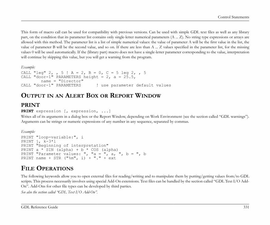
Control Statements
GDL Reference Guide 331
This form of macro call can be used for compatibility with previous versions. Can be used with simple GDL text files as well as any librarypart, on the condition that its parameter list contains only single-letter numerical parameters (A ... Z). No string type expressions or arrays areallowed with this method. The parameter list is a list of simple numerical values: the value of parameter A will be the first value in the list, thevalue of parameter B will be the second value, and so on. If there are less than A ... Z values specified in the parameter list, for the missingvalues 0 will be used automatically. If the (library part) macro does not have a single-letter parameter corresponding to the value, interpretationwill continue by skipping this value, but you will get a warning from the program.
Example:CALL "leg" 2, , 5 ! A = 2, B = 0, C = 5 leg 2, , 5CALL "door-1" PARAMETERS height = 2, a = 25.5, name = "Director"CALL "door-1" PARAMETERS ! use parameter default values
OUTPUT IN AN ALERT BOX OR REPORT WINDOW
PRINTPRINT expression [, expression, ...]Writes all of its arguments in a dialog box or the Report Window, depending on Work Environment (see the section called “GDL warnings”).Arguments can be strings or numeric expressions of any number in any sequence, separated by commas.
Example:PRINT "loop-variable:", iPRINT j, k-3*lPRINT "Beginning of interpretation"PRINT a * SIN (alpha) + b * COS (alpha)PRINT "Parameter values: ", "a = ", a, ", b = ", bPRINT name + STR ("%m", i) + "." + ext
FILE OPERATIONSThe following keywords allow you to open external files for reading/writing and to manipulate them by putting/getting values from/to GDLscripts. This process necessarily involves using special Add-On extensions. Text files can be handled by the section called “GDL Text I/O Add-On”. Add-Ons for other file types can be developed by third parties.See also the section called “GDL Text I/O Add-On”.
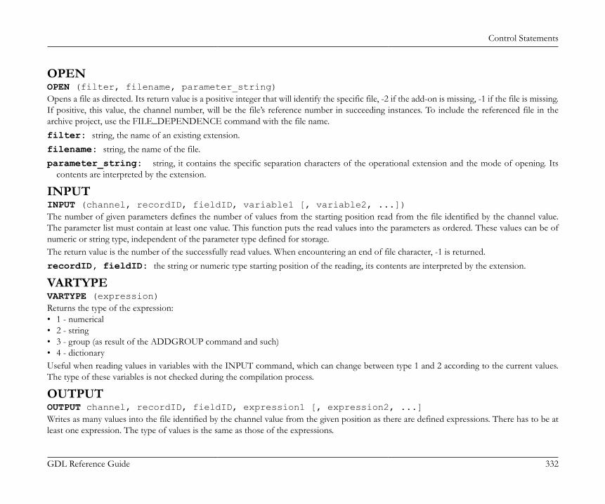
Control Statements
GDL Reference Guide 332
OPENOPEN (filter, filename, parameter_string)Opens a file as directed. Its return value is a positive integer that will identify the specific file, -2 if the add-on is missing, -1 if the file is missing.If positive, this value, the channel number, will be the file’s reference number in succeeding instances. To include the referenced file in thearchive project, use the FILE_DEPENDENCE command with the file name.filter: string, the name of an existing extension.filename: string, the name of the file.parameter_string: string, it contains the specific separation characters of the operational extension and the mode of opening. Its
contents are interpreted by the extension.
INPUTINPUT (channel, recordID, fieldID, variable1 [, variable2, ...])The number of given parameters defines the number of values from the starting position read from the file identified by the channel value.The parameter list must contain at least one value. This function puts the read values into the parameters as ordered. These values can be ofnumeric or string type, independent of the parameter type defined for storage.The return value is the number of the successfully read values. When encountering an end of file character, -1 is returned.recordID, fieldID: the string or numeric type starting position of the reading, its contents are interpreted by the extension.
VARTYPEVARTYPE (expression)Returns the type of the expression:• 1 - numerical• 2 - string• 3 - group (as result of the ADDGROUP command and such)• 4 - dictionaryUseful when reading values in variables with the INPUT command, which can change between type 1 and 2 according to the current values.The type of these variables is not checked during the compilation process.
OUTPUTOUTPUT channel, recordID, fieldID, expression1 [, expression2, ...]Writes as many values into the file identified by the channel value from the given position as there are defined expressions. There has to be atleast one expression. The type of values is the same as those of the expressions.
Control Statements
GDL Reference Guide 333
recordID, fieldID: the string or numeric type starting position of the writing; its contents are interpreted by the extension.
CLOSECLOSE channelCloses the file identified by the channel value.
USING DETERMINISTIC ADD-ONSThe following keywords allow you to call GDL add-ons which provide a deterministic function, i.e. the result of a given operation dependson the specified parameters only. This process necessarily involves using special Add-On extensions. For example polygon operations can beexecuted via the PolyOperations add-on. Add-Ons for other operations can be developed by third parties.See also the section called “Polygon Operations Extension”.
INITADDONSCOPEINITADDONSCOPE (extension, parameter_string1, parameter_string2)Opens a channel as directed. Its return value is a positive integer that will identify the specific connection. This value, the channel number, willbe the connection’s reference number in succeeding instances.extension: string, the name of an existing extension.parameter_string1: string, its contents are interpreted by the extension.parameter_string2: string, its contents are interpreted by the extension.
PREPAREFUNCTIONPREPAREFUNCTION channel, function_name, expression1 [, expression2, ...]Sets some values in the add-on as a preparation step for calling a later function.function_name: the string or numeric identifier of the function to be called; its contents are interpreted by the extension.expression: parameters to be passed for the preparation step.
CALLFUNCTIONCALLFUNCTION (channel, function_name, parameter, variable1 [, variable2, ...])The function named function_name in the add-on specified by channel is called. The parameter list must contain at least one value. This functionputs the returned values into the parameters as ordered. The return value is the number of the successfully set values.channel: channel value, used to identify the connection.
Control Statements
GDL Reference Guide 334
function_name: the string or numeric identifier of the function to be called; its contents are interpreted by the extension.parameter: input parameter; its contents are interpreted by the extension.variablei: output parameter.
CLOSEADDONSCOPECLOSEADDONSCOPE channelCloses the connection identified by the channel value.

Miscellaneous
GDL Reference Guide 335
MISCELLANEOUSGDL can also handle a number of operations on external files through special Add-On applications. The commands used to achieve this are described in this chapterand illustrated with an example.
GLOBAL VARIABLESThe global variables make it possible to store special values of the model. This allows you to access geometric information about the environmentof the GDL macro. For example, you can access the wall parameters when defining a window which has to fit into the wall. Global variablesare not stacked during macro calls.For doors, windows, labels and property library parts there is one more possibility to communicate with ARCHICAD through fix named,optional parameters. These parameters, if present on the library part’s parameter list, are set by ARCHICAD. See the list of fix named parametersand more details in the section called “Fix named optional parameters”.
Script compatibilityView or project dependent global variables should not be used in parameter scripts (or master scripts run as parameter script) to avoidthe parameter script run occasions and the resulting parameter values becoming context dependent, inconsistent within the planfile.Compatibility up to ARCHICAD 19: Such globals accidentally used in parameter script generate GDL warnings.Compatibility starting from ARCHICAD 20: Such globals used in parameter script generate GDL warnings, and will contain a static default value only (type-matching).Compatibility starting from ARCHICAD 22: View dependent global variables should not be used in property scripts (or master scripts run as property script). Suchinstances will cause warnings in scripts. However, project dependant variables are enabled in property script most cases.For compatibility details, check out the global variable descriptions. Script type restrictions apply where indicated.Legend
works without restriction
works (with additional warning)
contains dummy default value (with additional warning)
Miscellaneous
GDL Reference Guide 336
General environment informationGLOB_SCRIPT_TYPE type of current script
• 1 - properties script• 2 - 2D script• 3 - 3D script• 4 - user interface script• 5 - parameter script• 6 - master script• 7 - forward migration script• 8 - backward migration script
GLOB_VIEW_TYPE type of current view (view dependent, do not use in parameter/property scripts).
2D 3D UI Parameter Property Default -
• 2 - 2D (Floor Plan)• 3 - 3D• 4 - Section• 5 - Elevation• 6 - 3D Document• 7 - Detail• 8 - Layout• 9 - CalculationUse the exact needed values. Using ranges are not recommended due to possible future value extensions.
GLOB_PREVIEW_MODE type of current preview (view dependent, do not use in parameter/property scripts)
• 0 - None• 1 - Dialog• 2 - Listing• 3 - Favorite savingUse the exact needed values. Using ranges are not recommended due to possible future value extensions.
GLOB_FEEDBACK_MODE indicates editing in progress (view dependent, do not use in parameter/property scripts)
0 - off, 1 - editing feedback mode
Miscellaneous
GDL Reference Guide 337
GLOB_SEO_TOOL_MODE indicates solid element operations in progress (view dependent, do not use in parameter/propertyscripts)
0 - off, 1 - solid element operations mode
GLOB_DIAGNOSTICS_MODE Library Developer (59) menu command for GDL diagnostics
Compatibility: introduced in ARCHICAD 23.0 - off, 1 - onUse in scripts as a conditional statement to visualize debug content of library parts.
GLOB_SCALE drawing scale (view dependent, do not use in parameter/property scripts)
2D 3D UI Parameter Property Default 100
according to the current window
GLOB_DRAWING_BGD_PEN pen of the drawing background color (view dependent, do not use in parameter/property scripts)
2D 3D UI Parameter Property Default 19
the best matching (printable) pen from the current palette to the background color of the current window
GLOB_FILL_INDEX_SOLID index of fill type "Solid" according to the template (project dependent, do not use in parameterscript)
2D 3D UI Parameter Property Default 16
contains the applied index of the fill type "Solid"Compatibility: introduced in ARCHICAD 22.
GLOB_FILL_INDEX_BACKGROUND index of fill type "Background" according to the template (project dependent, do not use inparameter script)
2D 3D UI Parameter Property Default 16
contains the applied index of the fill type "Background"Compatibility: introduced in ARCHICAD 22.
GLOB_NORTH_DIR project North direction (project dependent, do not use in parameter script)
2D 3D UI Parameter Property Default 90
relative to the default project coordinate system according to the settings made in the Project Location dialog
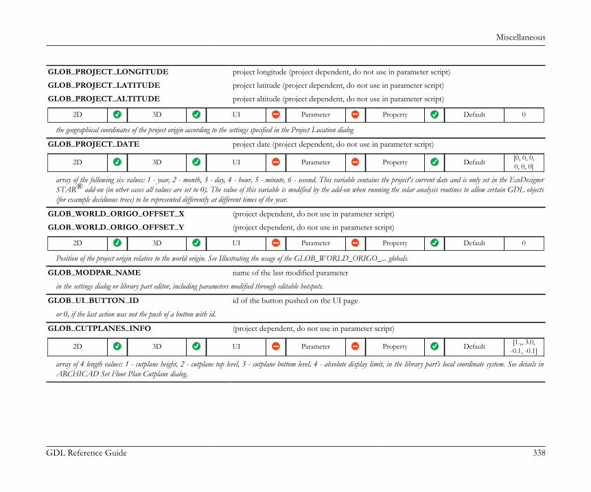
Miscellaneous
GDL Reference Guide 338
GLOB_PROJECT_LONGITUDE project longitude (project dependent, do not use in parameter script)
GLOB_PROJECT_LATITUDE project latitude (project dependent, do not use in parameter script)
GLOB_PROJECT_ALTITUDE project altitude (project dependent, do not use in parameter script)
2D 3D UI Parameter Property Default 0
the geographical coordinates of the project origin according to the settings specified in the Project Location dialog
GLOB_PROJECT_DATE project date (project dependent, do not use in parameter script)
2D 3D UI Parameter Property Default [0, 0, 0,0, 0, 0]
array of the following six values: 1 - year, 2 - month, 3 - day, 4 - hour, 5 - minute, 6 - second. This variable contains the project's current date and is only set in the EcoDesignerSTAR® add-on (in other cases all values are set to 0). The value of this variable is modified by the add-on when running the solar analysis routines to allow certain GDL objects(for example deciduous trees) to be represented differently at different times of the year.
GLOB_WORLD_ORIGO_OFFSET_X (project dependent, do not use in parameter script)
GLOB_WORLD_ORIGO_OFFSET_Y (project dependent, do not use in parameter script)
2D 3D UI Parameter Property Default 0
Position of the project origin relative to the world origin. See Illustrating the usage of the GLOB_WORLD_ORIGO_... globals.
GLOB_MODPAR_NAME name of the last modified parameter
in the settings dialog or library part editor, including parameters modified through editable hotspots.
GLOB_UI_BUTTON_ID id of the button pushed on the UI page
or 0, if the last action was not the push of a button with id.
GLOB_CUTPLANES_INFO (project dependent, do not use in parameter script)
2D 3D UI Parameter Property Default [1.,, 3.0,-0.1, -0.1]
array of 4 length values: 1 - cutplane height, 2 - cutplane top level, 3 - cutplane bottom level, 4 - absolute display limit, in the library part’s local coordinate system. See details inARCHICAD Set Floor Plan Cutplane dialog.

Miscellaneous
GDL Reference Guide 339
GLOB_STRUCTURE_DISPLAY structure display detail (project dependent, do not use in parameter script)
2D 3D UI Parameter Property Default 0
informs about the partial structure display option settings (integer): 0 - entire structure, 1 - core only, 2 - without finishes
GLOB_ISSUE_SCHEME list of custom data defined in the Issue Scheme
2D 3D UI Parameter Property Default -
Available in all context. 2-row string array, containing the names of fields defined in the Issue Scheme (first row), with the corresponding GUIDs (second row). The first five columnsare fixed: Revision ID, Issue ID, Issue Name, Issue Date, Issued by.For example:
Revision ID Issue ID Issue Name Issue Date Issued By Recipient Status ...
{RevIdGUID} {IssueIdGUID} {IssueNameGUID} {IssueDateGUID} {IssuedByGUID} {Custom1GUID} {Custom2GUID}
LAYOUT_REVISION_HISTORY list of the current Layout's Revision History
2D 3D UI Parameter Property Default -
Available in Layout context only. String array, containing 1 row per Revision, in the same structure as GLOB_ISSUE_SCHEME. The first five columns are fixed: RevisionID, Issue ID, Issue Name, Issue Date, Issued by.For example:
01 1 First Issue 2013-06-30 user1 Everyone SD ...
02 3 General Update 2013-07-31 user2 Mechanical DD
03 5 Structural Update 2013-08-31 user1 Structural DD
...
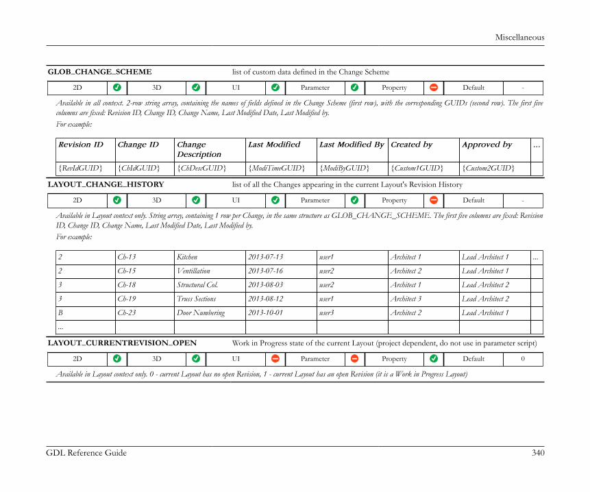
Miscellaneous
GDL Reference Guide 340
GLOB_CHANGE_SCHEME list of custom data defined in the Change Scheme
2D 3D UI Parameter Property Default -
Available in all context. 2-row string array, containing the names of fields defined in the Change Scheme (first row), with the corresponding GUIDs (second row). The first fivecolumns are fixed: Revision ID, Change ID, Change Name, Last Modified Date, Last Modified by.For example:
Revision ID Change ID ChangeDescription
Last Modified Last Modified By Created by Approved by ...
{RevIdGUID} {ChIdGUID} {ChDescGUID} {ModiTimeGUID} {ModiByGUID} {Custom1GUID} {Custom2GUID}
LAYOUT_CHANGE_HISTORY list of all the Changes appearing in the current Layout's Revision History
2D 3D UI Parameter Property Default -
Available in Layout context only. String array, containing 1 row per Change, in the same structure as GLOB_CHANGE_SCHEME. The first five columns are fixed: RevisionID, Change ID, Change Name, Last Modified Date, Last Modified by.For example:
2 Ch-13 Kitchen 2013-07-13 user1 Architect 1 Lead Architect 1 ...
2 Ch-15 Ventillation 2013-07-16 user2 Architect 2 Lead Architect 1
3 Ch-18 Structural Col. 2013-08-03 user2 Architect 1 Lead Architect 2
3 Ch-19 Truss Sections 2013-08-12 user1 Architect 3 Lead Architect 2
B Ch-23 Door Numbering 2013-10-01 user3 Architect 2 Lead Architect 1
...
LAYOUT_CURRENTREVISION_OPEN Work in Progress state of the current Layout (project dependent, do not use in parameter script)
2D 3D UI Parameter Property Default 0
Available in Layout context only. 0 - current Layout has no open Revision, 1 - current Layout has an open Revision (it is a Work in Progress Layout)

Miscellaneous
GDL Reference Guide 341
Story informationGLOB_HSTORY_ELEV elevation of the home story (project dependent, do not use in parameter script)
2D 3D UI Parameter Property Default 0
home story is the one the object is placed on
GLOB_HSTORY_HEIGHT height of the home story (project dependent, do not use in parameter script)
2D 3D UI Parameter Property Default 3.1
home story is the one the object is placed on
GLOB_CSTORY_ELEV elevation of the current story (project dependent, do not use in parameter script)
2D 3D UI Parameter Property Default 0.0
current story is the one currently shown in the Floor Plan window
GLOB_CSTORY_HEIGHT height of the current story (project dependent, do not use in parameter script)
2D 3D UI Parameter Property Default 3.1
current story is the one currently shown in the Floor Plan window
GLOB_CH_STORY_DIST relative position of the current story to the home story (project dependent, do not use in parameterscript)
2D 3D UI Parameter Property Default 0.0
current story is the one currently shown in the Floor Plan window
Fly-through informationGLOB_FRAME_NR current frame number in animation (view dependent, do not use in parameter/property scripts)
2D 3D UI Parameter Property Default -1
valid only for animation, -1 for still images
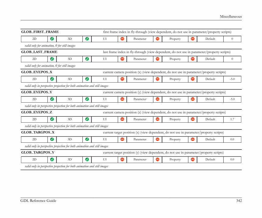
Miscellaneous
GDL Reference Guide 342
GLOB_FIRST_FRAME first frame index in fly-through (view dependent, do not use in parameter/property scripts)
2D 3D UI Parameter Property Default 0
valid only for animation, 0 for still images
GLOB_LAST_FRAME last frame index in fly-through (view dependent, do not use in parameter/property scripts)
2D 3D UI Parameter Property Default 0
valid only for animation, 0 for still images
GLOB_EYEPOS_X current camera position (x) (view dependent, do not use in parameter/property scripts)
2D 3D UI Parameter Property Default -5.0
valid only in perspective projection for both animation and still images
GLOB_EYEPOS_Y current camera position (y) (view dependent, do not use in parameter/property scripts)
2D 3D UI Parameter Property Default -5.0
valid only in perspective projection for both animation and still images
GLOB_EYEPOS_Z current camera position (z) (view dependent, do not use in parameter/property scripts)
2D 3D UI Parameter Property Default 1.7
valid only in perspective projection for both animation and still images
GLOB_TARGPOS_X current target position (x) (view dependent, do not use in parameter/property scripts)
2D 3D UI Parameter Property Default 0.0
valid only in perspective projection for both animation and still images
GLOB_TARGPOS_Y current target position (y) (view dependent, do not use in parameter/property scripts)
2D 3D UI Parameter Property Default 0.0
valid only in perspective projection for both animation and still images
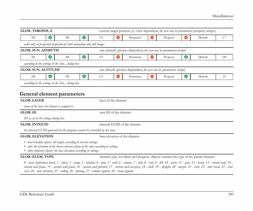
Miscellaneous
GDL Reference Guide 343
GLOB_TARGPOS_Z current target position (z) (view dependent, do not use in parameter/property scripts)
2D 3D UI Parameter Property Default 1.7
valid only in perspective projection for both animation and still images
GLOB_SUN_AZIMUTH sun azimuth (project dependent, do not use in parameter script)
2D 3D UI Parameter Property Default 240
according to the settings in the Sun... dialog box
GLOB_SUN_ALTITUDE sun altitude (project dependent, do not use in parameter script)
2D 3D UI Parameter Property Default 35
according to the settings in the Sun... dialog box
General element parametersGLOB_LAYER layer of the element
name of the layer the element is assigned to
GLOB_ID user ID of the element
ID as set in the settings dialog box
GLOB_INTGUID internal GUID of the element
the internal GUID generated by the program (cannot be controlled by the user)
GLOB_ELEVATION base elevation of the element
• door/window objects: sill height, according to current settings• slab: the elevation of the chosen reference plane of the slab, according to settings• other elements/objects: the base elevation, according to settings
GLOB_ELEM_TYPE element type, for labels and property objects contains the type of the parent element
0 - none (individual label), 1 - object, 2 - lamp, 3 - window, 4 - door, 5 - wall, 6 - column, 7 - slab, 8 - roof, 9 - fill, 10 - mesh, 11 - zone, 12 - beam, 13 - curtain wall, 14 -curtain wall frame, 15 - curtain wall panel, 16 - curtain wall junction, 17 - curtain wall accessory, 18 - shell, 19 - skylight, 20 - morph, 21 - stair, 22 - stair tread, 23 - stairriser, 24 - stair structure, 25 - railing, 26 - opening, 27 - column segment, 28 - beam segment.
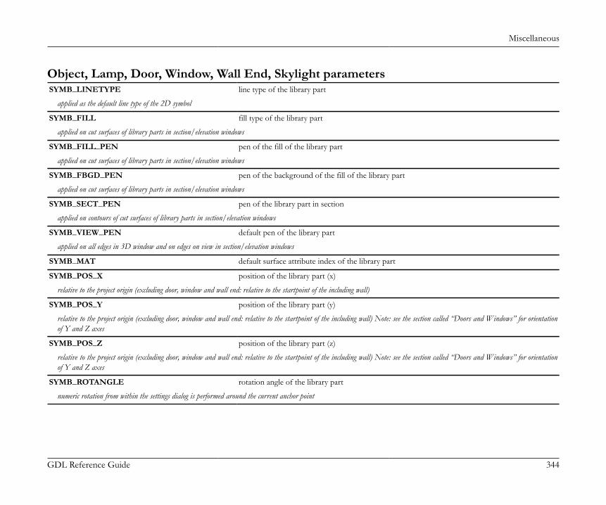
Miscellaneous
GDL Reference Guide 344
Object, Lamp, Door, Window, Wall End, Skylight parametersSYMB_LINETYPE line type of the library part
applied as the default line type of the 2D symbol
SYMB_FILL fill type of the library part
applied on cut surfaces of library parts in section/elevation windows
SYMB_FILL_PEN pen of the fill of the library part
applied on cut surfaces of library parts in section/elevation windows
SYMB_FBGD_PEN pen of the background of the fill of the library part
applied on cut surfaces of library parts in section/elevation windows
SYMB_SECT_PEN pen of the library part in section
applied on contours of cut surfaces of library parts in section/elevation windows
SYMB_VIEW_PEN default pen of the library part
applied on all edges in 3D window and on edges on view in section/elevation windows
SYMB_MAT default surface attribute index of the library part
SYMB_POS_X position of the library part (x)
relative to the project origin (excluding door, window and wall end: relative to the startpoint of the including wall)
SYMB_POS_Y position of the library part (y)
relative to the project origin (excluding door, window and wall end: relative to the startpoint of the including wall) Note: see the section called “Doors and Windows” for orientationof Y and Z axes
SYMB_POS_Z position of the library part (z)
relative to the project origin (excluding door, window and wall end: relative to the startpoint of the including wall) Note: see the section called “Doors and Windows” for orientationof Y and Z axes
SYMB_ROTANGLE rotation angle of the library part
numeric rotation from within the settings dialog is performed around the current anchor point
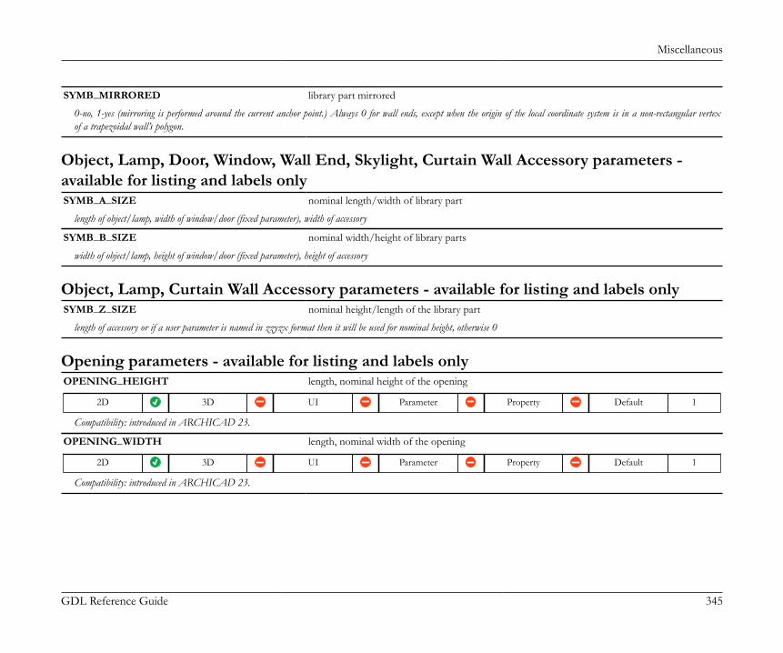
Miscellaneous
GDL Reference Guide 345
SYMB_MIRRORED library part mirrored
0-no, 1-yes (mirroring is performed around the current anchor point.) Always 0 for wall ends, except when the origin of the local coordinate system is in a non-rectangular vertexof a trapezoidal wall’s polygon.
Object, Lamp, Door, Window, Wall End, Skylight, Curtain Wall Accessory parameters -available for listing and labels onlySYMB_A_SIZE nominal length/width of library part
length of object/lamp, width of window/door (fixed parameter), width of accessory
SYMB_B_SIZE nominal width/height of library parts
width of object/lamp, height of window/door (fixed parameter), height of accessory
Object, Lamp, Curtain Wall Accessory parameters - available for listing and labels onlySYMB_Z_SIZE nominal height/length of the library part
length of accessory or if a user parameter is named in zzyzx format then it will be used for nominal height, otherwise 0
Opening parameters - available for listing and labels onlyOPENING_HEIGHT length, nominal height of the opening
2D 3D UI Parameter Property Default 1
Compatibility: introduced in ARCHICAD 23.
OPENING_WIDTH length, nominal width of the opening
2D 3D UI Parameter Property Default 1
Compatibility: introduced in ARCHICAD 23.
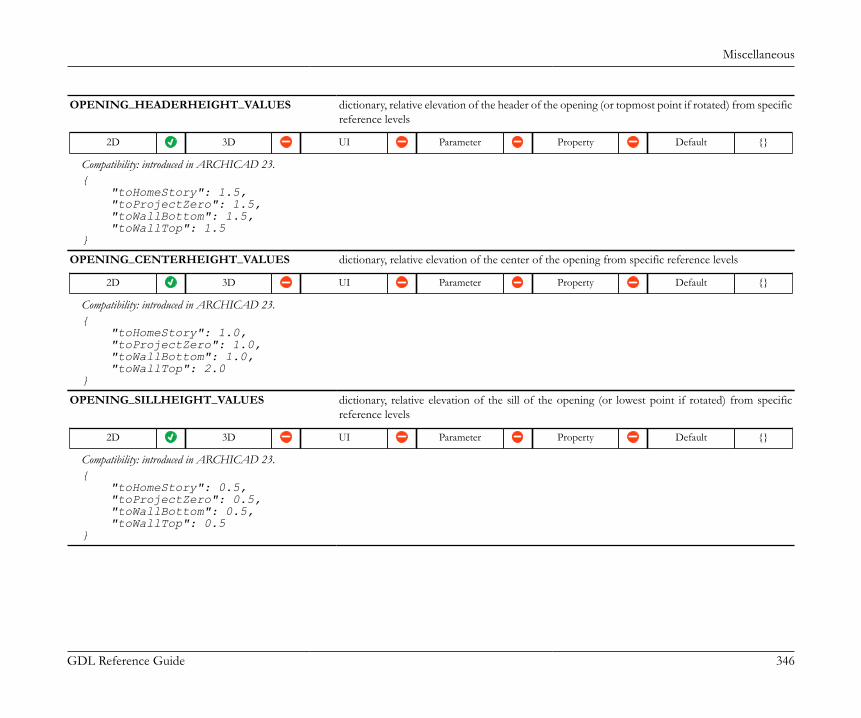
Miscellaneous
GDL Reference Guide 346
OPENING_HEADERHEIGHT_VALUES dictionary, relative elevation of the header of the opening (or topmost point if rotated) from specificreference levels
2D 3D UI Parameter Property Default {}
Compatibility: introduced in ARCHICAD 23.{ "toHomeStory": 1.5, "toProjectZero": 1.5, "toWallBottom": 1.5, "toWallTop": 1.5}
OPENING_CENTERHEIGHT_VALUES dictionary, relative elevation of the center of the opening from specific reference levels
2D 3D UI Parameter Property Default {}
Compatibility: introduced in ARCHICAD 23.{ "toHomeStory": 1.0, "toProjectZero": 1.0, "toWallBottom": 1.0, "toWallTop": 2.0}
OPENING_SILLHEIGHT_VALUES dictionary, relative elevation of the sill of the opening (or lowest point if rotated) from specificreference levels
2D 3D UI Parameter Property Default {}
Compatibility: introduced in ARCHICAD 23.{ "toHomeStory": 0.5, "toProjectZero": 0.5, "toWallBottom": 0.5, "toWallTop": 0.5}

Miscellaneous
GDL Reference Guide 347
Opening symbol parametersOPENING_SYMBOL_DISPLAY integer, visibility of the opening symbol according to the Floor Plan Cut Plane (view dependent,
do not use in parameter/property scripts)
2D 3D UI Parameter Property Default 1
Compatibility: introduced in ARCHICAD 23.1 - visible, 2 - hidden, 3 - overhead
OPENING_SYMBOL_GEOMETRY dictionary, contains the geometry of the symbol (view dependent, do not use in parameter/propertyscripts)
2D 3D UI Parameter Property Default {}
Compatibility: introduced in ARCHICAD 23.• .boundingBox2D{}: (dictionary) bounding box definition of the opening polygon, always aligned with the opening symbol coordinate system.• .boundingBox2D.xmin• .boundingBox2D.xmax• .boundingBox2D.ymin• .boundingBox2D.ymax• .polygon2D{}: (dictionary) projected polygon of the opening cut by the geometry of the parent element• .polygon2D.isClosed: (boolean) always 1 in case of a polygon (0 - reserved for future developments)• .polygon2D.contour{}: (dictionary) contains data of the polygon contour. The default polygon corresponds to the rectangle in .boundingBox2D{}• .polygon2D.contour.edges[n]: (array) contains an embedded dictionary for each edge of the polygon• .polygon2D.contour.edges[n].type: (integer) 0 - straight, 1 - curved (circular arc)• .polygon2D.contour.edges[n].begPoint{}: (dictionary) an embedded dictionary for the coordinates of the beginning point of the edge• .polygon2D.contour.edges[n].arcAngle: (angle) central angle of the edge curve, positive counter-clockwise, negative clockwise (not set for straight edges)• .polygon2D.holes[m]: (array) contains data of inner holes, similar to .contour, only set when holes exist

Miscellaneous
GDL Reference Guide 348
OPENING_SYMBOL_GEOMETRY: { "boundingBox2D": { "xmin": 0, "xmax": 1, "ymin": 0, "ymax": 1 }, "polygon2D": { "isClosed": 1, "contour": { "edges": [ { "type": 1, "begPoint": { "x": 1, "y": 0.5 }, "arcAngle": 90 }, { "type": 1, "begPoint": { "x": 0.5, "y": 1 }, "arcAngle": 90 }, { "type": 1, "begPoint": { "x": 0, "y": 0.5 }, "arcAngle": 90 },
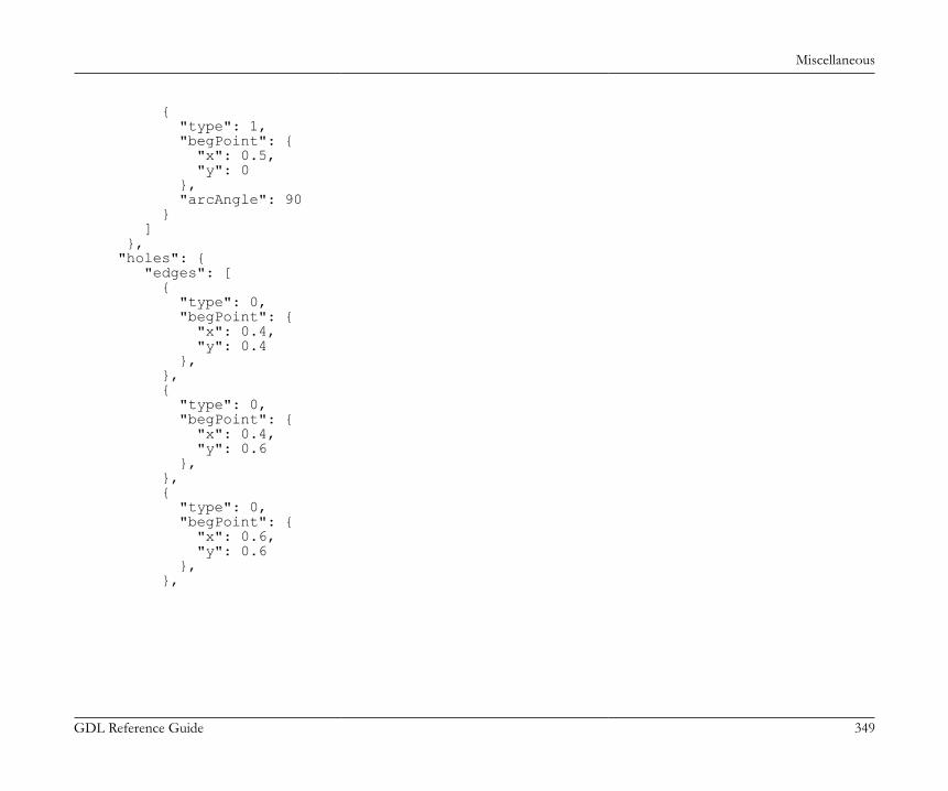
Miscellaneous
GDL Reference Guide 349
{ "type": 1, "begPoint": { "x": 0.5, "y": 0 }, "arcAngle": 90 } ] }, "holes": { "edges": [ { "type": 0, "begPoint": { "x": 0.4, "y": 0.4 }, }, { "type": 0, "begPoint": { "x": 0.4, "y": 0.6 }, }, { "type": 0, "begPoint": { "x": 0.6, "y": 0.6 }, },
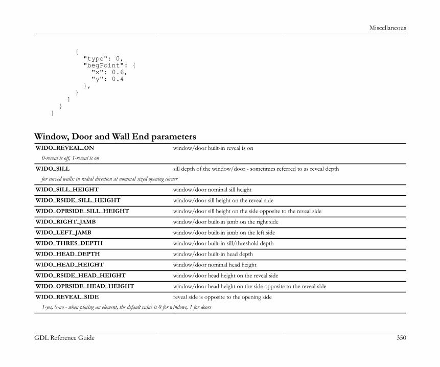
Miscellaneous
GDL Reference Guide 350
{ "type": 0, "begPoint": { "x": 0.6, "y": 0.4 }, } ] } }
Window, Door and Wall End parametersWIDO_REVEAL_ON window/door built-in reveal is on
0-reveal is off, 1-reveal is on
WIDO_SILL sill depth of the window/door - sometimes referred to as reveal depth
for curved walls: in radial direction at nominal sized opening corner
WIDO_SILL_HEIGHT window/door nominal sill height
WIDO_RSIDE_SILL_HEIGHT window/door sill height on the reveal side
WIDO_OPRSIDE_SILL_HEIGHT window/door sill height on the side opposite to the reveal side
WIDO_RIGHT_JAMB window/door built-in jamb on the right side
WIDO_LEFT_JAMB window/door built-in jamb on the left side
WIDO_THRES_DEPTH window/door built-in sill/threshold depth
WIDO_HEAD_DEPTH window/door built-in head depth
WIDO_HEAD_HEIGHT window/door nominal head height
WIDO_RSIDE_HEAD_HEIGHT window/door head height on the reveal side
WIDO_OPRSIDE_HEAD_HEIGHT window/door head height on the side opposite to the reveal side
WIDO_REVEAL_SIDE reveal side is opposite to the opening side
1-yes, 0-no - when placing an element, the default value is 0 for windows, 1 for doors
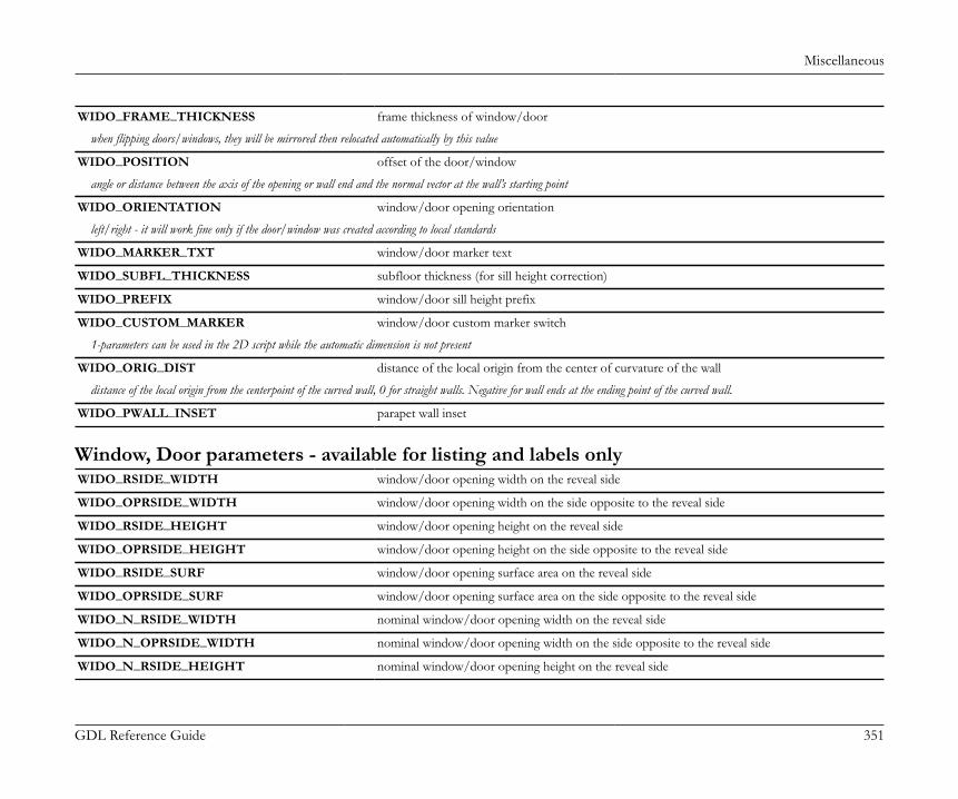
Miscellaneous
GDL Reference Guide 351
WIDO_FRAME_THICKNESS frame thickness of window/door
when flipping doors/windows, they will be mirrored then relocated automatically by this value
WIDO_POSITION offset of the door/window
angle or distance between the axis of the opening or wall end and the normal vector at the wall’s starting point
WIDO_ORIENTATION window/door opening orientation
left/right - it will work fine only if the door/window was created according to local standards
WIDO_MARKER_TXT window/door marker text
WIDO_SUBFL_THICKNESS subfloor thickness (for sill height correction)
WIDO_PREFIX window/door sill height prefix
WIDO_CUSTOM_MARKER window/door custom marker switch
1-parameters can be used in the 2D script while the automatic dimension is not present
WIDO_ORIG_DIST distance of the local origin from the center of curvature of the wall
distance of the local origin from the centerpoint of the curved wall, 0 for straight walls. Negative for wall ends at the ending point of the curved wall.
WIDO_PWALL_INSET parapet wall inset
Window, Door parameters - available for listing and labels onlyWIDO_RSIDE_WIDTH window/door opening width on the reveal side
WIDO_OPRSIDE_WIDTH window/door opening width on the side opposite to the reveal side
WIDO_RSIDE_HEIGHT window/door opening height on the reveal side
WIDO_OPRSIDE_HEIGHT window/door opening height on the side opposite to the reveal side
WIDO_RSIDE_SURF window/door opening surface area on the reveal side
WIDO_OPRSIDE_SURF window/door opening surface area on the side opposite to the reveal side
WIDO_N_RSIDE_WIDTH nominal window/door opening width on the reveal side
WIDO_N_OPRSIDE_WIDTH nominal window/door opening width on the side opposite to the reveal side
WIDO_N_RSIDE_HEIGHT nominal window/door opening height on the reveal side
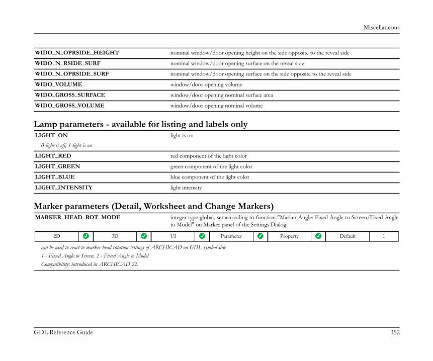
Miscellaneous
GDL Reference Guide 352
WIDO_N_OPRSIDE_HEIGHT nominal window/door opening height on the side opposite to the reveal side
WIDO_N_RSIDE_SURF nominal window/door opening surface on the reveal side
WIDO_N_OPRSIDE_SURF nominal window/door opening surface on the side opposite to the reveal side
WIDO_VOLUME window/door opening volume
WIDO_GROSS_SURFACE window/door opening nominal surface area
WIDO_GROSS_VOLUME window/door opening nominal volume
Lamp parameters - available for listing and labels onlyLIGHT_ON light is on
0-light is off, 1-light is on
LIGHT_RED red component of the light color
LIGHT_GREEN green component of the light color
LIGHT_BLUE blue component of the light color
LIGHT_INTENSITY light intensity
Marker parameters (Detail, Worksheet and Change Markers)MARKER_HEAD_ROT_MODE integer type global, set according to function "Marker Angle: Fixed Angle to Screen/Fixed Angle
to Model" on Marker panel of the Settings Dialog
2D 3D UI Parameter Property Default 1
can be used to react to marker head rotation settings of ARCHICAD on GDL symbol side1 - Fixed Angle to Screen, 2 - Fixed Angle to ModelCompatibility: introduced in ARCHICAD 22.
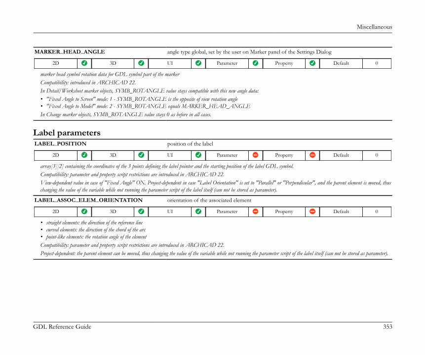
Miscellaneous
GDL Reference Guide 353
MARKER_HEAD_ANGLE angle type global, set by the user on Marker panel of the Settings Dialog
2D 3D UI Parameter Property Default 0
marker head symbol rotation data for GDL symbol part of the markerCompatibility: introduced in ARCHICAD 22.In Detail/Worksheet marker objects, SYMB_ROTANGLE value stays compatible with this new angle data:• "Fixed Angle to Screen" mode: 1 - SYMB_ROTANGLE is the opposite of view rotation angle• "Fixed Angle to Model" mode: 2 - SYMB_ROTANGLE equals MARKER_HEAD_ANGLEIn Change marker objects, SYMB_ROTANGLE value stays 0 as before in all cases.
Label parametersLABEL_POSITION position of the label
2D 3D UI Parameter Property Default 0
array[3][2] containing the coordinates of the 3 points defining the label pointer and the starting position of the label GDL symbol.Compatibility: parameter and property script restrictions are introduced in ARCHICAD 22.View-dependent value in case of "Fixed Angle" ON. Project-dependent in case "Label Orientation" is set to "Parallel" or "Perpendicular", and the parent element is moved, thuschanging the value of the variable while not running the parameter script of the label itself (can not be stored as parameter).
LABEL_ASSOC_ELEM_ORIENTATION orientation of the associated element
2D 3D UI Parameter Property Default 0
• straight elements: the direction of the reference line• curved elements: the direction of the chord of the arc• point-like elements: the rotation angle of the elementCompatibility: parameter and property script restrictions are introduced in ARCHICAD 22.Project-dependent: the parent element can be moved, thus changing the value of the variable while not running the parameter script of the label itself (can not be stored as parameter).

Miscellaneous
GDL Reference Guide 354
LABEL_ROTANGLE absolute rotation angle data for GDL symbol type labels
2D 3D UI Parameter Property Default 0
The angle is calculated according to Label Orientation, Fixed Angle, and readability settings.Compatibility: parameter and property script restrictions are introduced in ARCHICAD 22.View-dependent value in case of "Fixed Angle" ON. Project-dependent in case "Label Orientation" is set to "Parallel" or "Perpendicular": the parent element can be moved, thuschanging the value of the variable.
LABEL_ARROWHEAD_PEN pen of the arrowhead
LABEL_HAS_POINTER Boolean
1 - "Add/Remove Pointer" is checked on "Label Settings/Pointer" panel, 0 otherwise.Compatibility: introduced in ARCHICAD 22. The similar, reverse-working global variable "LABEL_CUSTOM_ARROW" is considered deprecated since ARCHICAD 22.
Wall parameters - available for Doors/Windows, listing and labelsWALL_ID user ID of the wall
WALL_INTGUID internal GUID of the wall
the internal GUID generated by the program (cannot be controlled by the user)
WALL_RESOL 3D resolution of a curved wall
effective in 3D only
WALL_THICKNESS thickness of the wall
in case of inclined walls: the wall thickness at the opening axis (local z axis)
WALL_START_THICKNESS Start thickness of the wall
WALL_END_THICKNESS End thickness of the wall
WALL_INCL inclination of the wall surfaces
the angle between the two inclined wall surfaces - 0 for common straight walls
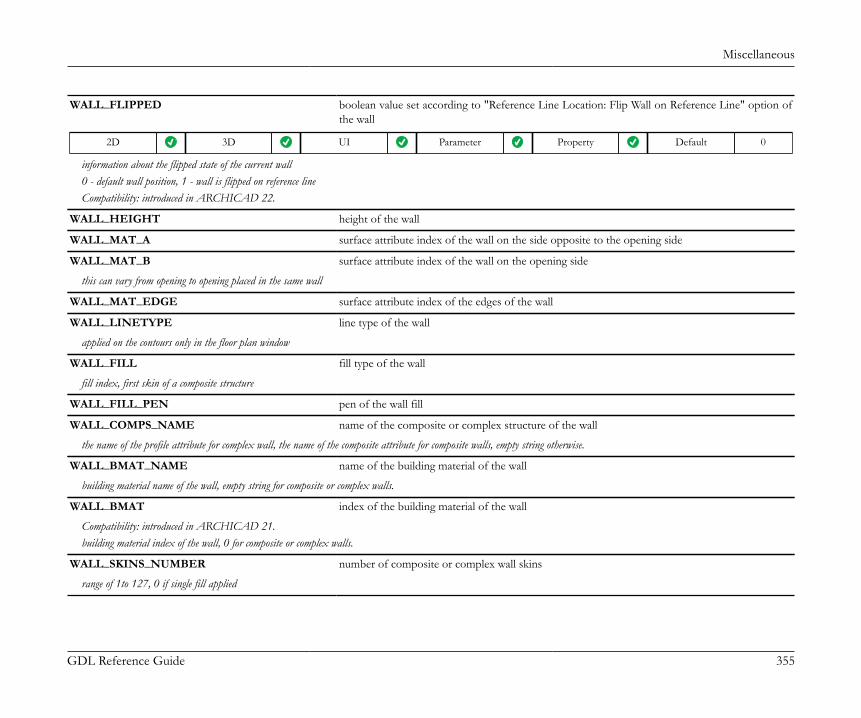
Miscellaneous
GDL Reference Guide 355
WALL_FLIPPED boolean value set according to "Reference Line Location: Flip Wall on Reference Line" option ofthe wall
2D 3D UI Parameter Property Default 0
information about the flipped state of the current wall0 - default wall position, 1 - wall is flipped on reference lineCompatibility: introduced in ARCHICAD 22.
WALL_HEIGHT height of the wall
WALL_MAT_A surface attribute index of the wall on the side opposite to the opening side
WALL_MAT_B surface attribute index of the wall on the opening side
this can vary from opening to opening placed in the same wall
WALL_MAT_EDGE surface attribute index of the edges of the wall
WALL_LINETYPE line type of the wall
applied on the contours only in the floor plan window
WALL_FILL fill type of the wall
fill index, first skin of a composite structure
WALL_FILL_PEN pen of the wall fill
WALL_COMPS_NAME name of the composite or complex structure of the wall
the name of the profile attribute for complex wall, the name of the composite attribute for composite walls, empty string otherwise.
WALL_BMAT_NAME name of the building material of the wall
building material name of the wall, empty string for composite or complex walls.
WALL_BMAT index of the building material of the wall
Compatibility: introduced in ARCHICAD 21.building material index of the wall, 0 for composite or complex walls.
WALL_SKINS_NUMBER number of composite or complex wall skins
range of 1to 127, 0 if single fill applied

Miscellaneous
GDL Reference Guide 356
WALL_SKINS_PARAMS parameters of the composite or complex wall skins
array with 19 columns with arbitrary number of rows:• [1] fill• [2] thickness• [3] (old contour pen)• [4] pen of fill• [5] pen of fill background• [6] core status• [7] upper line pen• [8] upper line type• [9] lower line pen• [10] lower line type• [11] end face pen• [12] fill orientation• [13] skin type• [14] end face line type• [15] finish skin status• [16] oriented fill status• [17] trapezoid/double slanted status• [18] building material index• [19] skin edge surface index (considering wall edge surface override). Compatibility: introduced in ARCHICAD 22.core status: 0 - not part, 1 - part, 3 - last core skin.fill orientation: 0 - global, 1 - local.skin type: 0 - cut, 1 - below cutplane, 2 - above cutplane (all skin types are 0 for simple walls).trapezoid/double slanted: 0 - this skin has parallel faces in all circumstances, 1 - this skin might have non-parallel faces to adjust for the width difference of trapezoid walls or doubleslanted walls. Even if the wall faces are parallel, this flag can be turned on.finish skin status: 0 - not finish skin, 1 - finish skin.oriented fill status: 0 - global or local fill orientation as set in the "fill orientation" column, 1 - fill orientation and size match with the wall skin direction and thickness.For complex walls this variable contains only the data of the skins that are cut on the floor plan (2D - regarding floor plan cut height), or cut at D/W sill / wall end bottom height (3D).
WALL_SKINS_BMAT_NAMES building material names of the composite or complex wall skins
array with 1 column: building material name of the skin and with arbitrary number of rows.For D/W and wall ends in the 3D window contains the data of the skins actually cut by the D/W or wall end.

Miscellaneous
GDL Reference Guide 357
WALL_SECT_PEN pen of the contours of the wall cut surfaces
applied on contours of cut surfaces both in floor plan and section/elevation windows
WALL_VIEW_PEN pen of the contours of the wall on view
applied on all edges in 3D window and on outline edges (edges on view below cutting plane) in floor plan and section/elevation window
WALL_FBGD_PEN pen of the background of the fill of the wall
WALL_DIRECTION direction of the wall
straight walls: the direction of the reference line, curved walls: the direction of the chord of the arc
WALL_POSITION absolute coordinates of the wall
array with 3 columns: x, y, z, which means the position of the wall’s starting point relative to the project origin
WALL_TEXTURE_WRAP texture wrapping data of the wall to be used in VERT and COOR{2}, or COOR{3} commands.The wall texture coordinates are transformed to match the local coordinate system of the wall-connected object (no additional transformations needed).
array with 14 rows:• [1]: wrapping_method• [2]: wrap_flags• [3]-[4]-[5]: origin_X, origin_Y, origin_Z (nodes of vert 1)• [6]-[7]-[8]: endOfX_X, endOfX_Y, endOfX_Z (nodes of vert 2)• [9]-[10]-[11]: endOfY_X, endOfY_Y, endOfY_Z (nodes of vert 3)• [12]-[13]-[14]: endOfZ_X, endOfZ_Y, endOfZ_Z (nodes of vert 4)
Wall parameters - available for listing and labels onlyWALL_LENGTH_A length of the wall on the reference line side
WALL_LENGTH_B length of the wall on the side opposite to the reference line
WALL_LENGTH_A_CON conditional wall length on the reference line side
WALL_LENGTH_B_CON conditional wall length on the side opposite to the reference line
WALL_CENTER_LENGTH length of the wall at the center
WALL_AREA area of the wall
WALL_PERIMETER perimeter of the wall

Miscellaneous
GDL Reference Guide 358
WALL_SURFACE_A surface area of the wall on the reference line side
WALL_SURFACE_B surface area of the wall on the side opposite to the reference line
WALL_SURFACE_A_CON conditional wall surface area on the reference line side
WALL_SURFACE_B_CON conditional wall surface area on the side opposite to the reference line
WALL_GROSS_SURFACE_A gross surface area of the wall on the reference line side
WALL_GROSS_SURFACE_B gross surface area of the wall on the side opposite to the reference line
WALL_EDGE_SURF surface area of the edge of the wall
WALL_VOLUME volume of the wall
WALL_VOLUME_CON conditional volume of the wall
WALL_GROSS_VOLUME gross volume of the wall
WALL_VOLUME_A wall skin volume on the reference line side
WALL_VOLUME_A_CON conditional wall skin volume on the reference line side
WALL_VOLUME_B wall skin volume on the side opposite to the reference line
WALL_VOLUME_B_CON conditional wall skin volume on the side opposite to the reference line
WALL_DOORS_NR number of doors in the wall
WALL_WINDS_NR number of windows in the wall
WALL_HOLES_NR number of empty openings
WALL_DOORS_SURF surface area of doors in the wall
WALL_WINDS_SURF surface area of windows in the wall
WALL_HOLES_SURF surface area of empty openings in the wall
WALL_HOLES_SURF_A analytic surface area of openings on the reference line side
WALL_HOLES_SURF_B analytic surface area of openings on the opposite side
WALL_HOLES_VOLUME analytic volume of openings in the wall
WALL_WINDS_WID combined width of the windows in the wall
WALL_DOORS_WID combined width of the doors in the wall

Miscellaneous
GDL Reference Guide 359
WALL_COLUMNS_NR number of columns in the wall
WALL_CROSSSECTION_TYPE cross-section type of the wall
0 - complex profiled, 1 - rectangular, 2 - slanted, 3 - double slanted
WALL_MIN_HEIGHT minimum height of the wall
WALL_MAX_HEIGHT maximum height of the wall
WALL_SKIN_MIN_HEIGHT_A minimum height of the wall skin on the reference line side
WALL_SKIN_MAX_HEIGHT_A maximum height of the wall skin on the reference line side
WALL_SKIN_MIN_HEIGHT_B minimum height of the wall skin on the reference line side
WALL_SKIN_MAX_HEIGHT_B maximum height of the wall skin on the side opposite to the reference line
WALL_SKIN_THICKNESS_A wall skin thickness on the reference line side
WALL_SKIN_THICKNESS_B wall skin thickness on the side opposite to the reference line
WALL_INSU_THICKNESS wall insulation skin thickness
WALL_AIR_THICKNESS wall air skin thickness
Column parameters - available for listing and labels onlyCompatibility: From ARCHICAD 23, the Column element is a collection of Column Segments. GLOB_ELEM_TYPE has a new value forColumn segments: 27, the value of the Column element remains 6.The availability of each global variable (whether it contains meaningful data) is shown in a table with icons, with the value of theGLOB_ELEM_TYPE global variable in parentheses.
COLU_SEGMENT_INDEX index of Column Segment in COLU_SEGMENT_INFO.segments[] array
Column Segment (27) Single-segment Column (6) Multi-segment Column (6)
Compatibility: introduced in ARCHICAD 23.
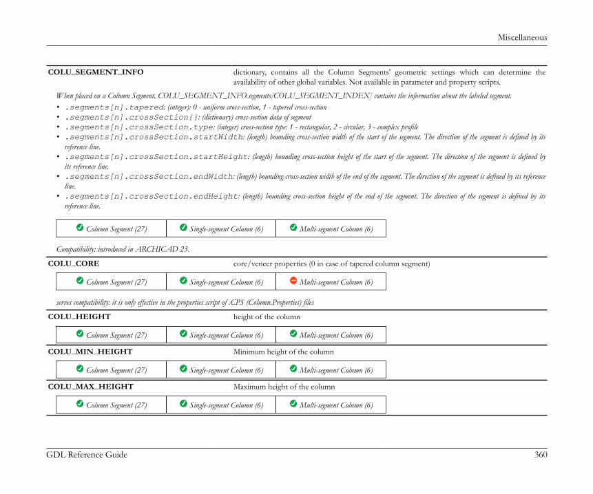
Miscellaneous
GDL Reference Guide 360
COLU_SEGMENT_INFO dictionary, contains all the Column Segments' geometric settings which can determine theavailability of other global variables. Not available in parameter and property scripts.
When placed on a Column Segment, COLU_SEGMENT_INFO.segments[COLU_SEGMENT_INDEX] contains the information about the labeled segment.• .segments[n].tapered: (integer): 0 - uniform cross-section, 1 - tapered cross-section• .segments[n].crossSection{}: (dictionary) cross-section data of segment• .segments[n].crossSection.type: (integer) cross-section type: 1 - rectangular, 2 - circular, 3 - complex profile• .segments[n].crossSection.startWidth: (length) bounding cross-section width of the start of the segment. The direction of the segment is defined by its
reference line.• .segments[n].crossSection.startHeight: (length) bounding cross-section height of the start of the segment. The direction of the segment is defined by
its reference line.• .segments[n].crossSection.endWidth: (length) bounding cross-section width of the end of the segment. The direction of the segment is defined by its reference
line.• .segments[n].crossSection.endHeight: (length) bounding cross-section height of the end of the segment. The direction of the segment is defined by its
reference line.
Column Segment (27) Single-segment Column (6) Multi-segment Column (6)
Compatibility: introduced in ARCHICAD 23.
COLU_CORE core/veneer properties (0 in case of tapered column segment)
Column Segment (27) Single-segment Column (6) Multi-segment Column (6)
serves compatibility: it is only effective in the properties script of .CPS (Column.Properties) files
COLU_HEIGHT height of the column
Column Segment (27) Single-segment Column (6) Multi-segment Column (6)
COLU_MIN_HEIGHT Minimum height of the column
Column Segment (27) Single-segment Column (6) Multi-segment Column (6)
COLU_MAX_HEIGHT Maximum height of the column
Column Segment (27) Single-segment Column (6) Multi-segment Column (6)
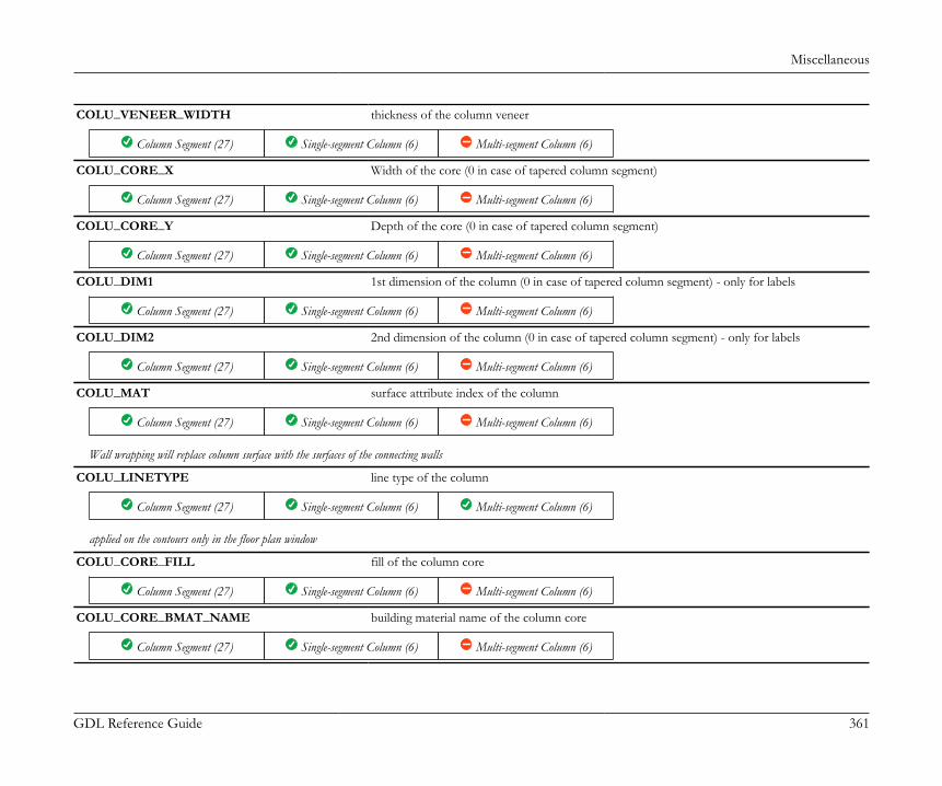
Miscellaneous
GDL Reference Guide 361
COLU_VENEER_WIDTH thickness of the column veneer
Column Segment (27) Single-segment Column (6) Multi-segment Column (6)
COLU_CORE_X Width of the core (0 in case of tapered column segment)
Column Segment (27) Single-segment Column (6) Multi-segment Column (6)
COLU_CORE_Y Depth of the core (0 in case of tapered column segment)
Column Segment (27) Single-segment Column (6) Multi-segment Column (6)
COLU_DIM1 1st dimension of the column (0 in case of tapered column segment) - only for labels
Column Segment (27) Single-segment Column (6) Multi-segment Column (6)
COLU_DIM2 2nd dimension of the column (0 in case of tapered column segment) - only for labels
Column Segment (27) Single-segment Column (6) Multi-segment Column (6)
COLU_MAT surface attribute index of the column
Column Segment (27) Single-segment Column (6) Multi-segment Column (6)
Wall wrapping will replace column surface with the surfaces of the connecting walls
COLU_LINETYPE line type of the column
Column Segment (27) Single-segment Column (6) Multi-segment Column (6)
applied on the contours only in the floor plan window
COLU_CORE_FILL fill of the column core
Column Segment (27) Single-segment Column (6) Multi-segment Column (6)
COLU_CORE_BMAT_NAME building material name of the column core
Column Segment (27) Single-segment Column (6) Multi-segment Column (6)

Miscellaneous
GDL Reference Guide 362
COLU_CORE_BMAT building material index of the column core
Column Segment (27) Single-segment Column (6) Multi-segment Column (6)
Compatibility: introduced in ARCHICAD 21.
COLU_VENEER_FILL fill of the column veneer
Column Segment (27) Single-segment Column (6) Multi-segment Column (6)
COLU_VENEER_BMAT_NAME building material name of the column veneer
Column Segment (27) Single-segment Column (6) Multi-segment Column (6)
COLU_VENEER_BMAT building material index of the column veneer
Column Segment (27) Single-segment Column (6) Multi-segment Column (6)
Compatibility: introduced in ARCHICAD 21.
COLU_SECT_PEN pen of the contours of the column cut surfaces
Column Segment (27) Single-segment Column (6) Multi-segment Column (6)
applied on contours of cut surfaces in both floor plan and section/elevation windows
COLU_VIEW_PEN pen of the column on view
Column Segment (27) Single-segment Column (6) Multi-segment Column (6)
applied on all edges in 3D window and on outline edges (edges on view below cutting plane) in floor plan and section/elevation windows
COLU_CORE_FILL_PEN pen of the fill of the column core
Column Segment (27) Single-segment Column (6) Multi-segment Column (6)
COLU_CORE_FBGD_PEN pen of the background of the fill of the column core
Column Segment (27) Single-segment Column (6) Multi-segment Column (6)

Miscellaneous
GDL Reference Guide 363
COLU_VENEER_FILL_PEN pen of the fill of the column veneer
Column Segment (27) Single-segment Column (6) Multi-segment Column (6)
COLU_VENEER_FBGD_PEN pen of the background of the fill of the column veneer
Column Segment (27) Single-segment Column (6) Multi-segment Column (6)
COLU_PERIMETER Perimeter of the column
Column Segment (27) Single-segment Column (6) Multi-segment Column (6)
COLU_AREA Area of the column
Column Segment (27) Single-segment Column (6) Multi-segment Column (6)
COLU_VOLUME Volume of the column
Column Segment (27) Single-segment Column (6) Multi-segment Column (6)
COLU_GROSS_VOLUME Gross volume of the column
Column Segment (27) Single-segment Column (6) Multi-segment Column (6)
COLU_CORE_SURF surface area of the column core
Column Segment (27) Single-segment Column (6) Multi-segment Column (6)
COLU_CORE_GROSS_SURF Gross surface area of the column
Column Segment (27) Single-segment Column (6) Multi-segment Column (6)
COLU_CORE_VOL volume of the column core
Column Segment (27) Single-segment Column (6) Multi-segment Column (6)
COLU_CORE_GROSS_VOL Gross volume of the core
Column Segment (27) Single-segment Column (6) Multi-segment Column (6)

Miscellaneous
GDL Reference Guide 364
COLU_VENEER_SURF surface area of the column veneer
Column Segment (27) Single-segment Column (6) Multi-segment Column (6)
COLU_VENEER_GROSS_SURF Gross surface area of the veneer
Column Segment (27) Single-segment Column (6) Multi-segment Column (6)
COLU_VENEER_VOL volume of the column veneer
Column Segment (27) Single-segment Column (6) Multi-segment Column (6)
COLU_VENEER_GROSS_VOL Gross volume of the veneer
Column Segment (27) Single-segment Column (6) Multi-segment Column (6)
COLU_CORE_TOP_SURF Surface area of the core top
Column Segment (27) Single-segment Column (6) Multi-segment Column (6)
COLU_CORE_BOT_SURF Surface area of the core bottom
Column Segment (27) Single-segment Column (6) Multi-segment Column (6)
COLU_VENEER_TOP_SURF Surface area of the veneer top
Column Segment (27) Single-segment Column (6) Multi-segment Column (6)
COLU_VENEER_BOT_SURF Surface area of the veneer bottom
Column Segment (27) Single-segment Column (6) Multi-segment Column (6)
COLU_CORE_GROSS_TOPBOT_SURF Gross surface area of the core top and bottom
Column Segment (27) Single-segment Column (6) Multi-segment Column (6)
COLU_VENEER_GROSS_TOPBOT_SURF Gross surface area of the veneer top and bottom
Column Segment (27) Single-segment Column (6) Multi-segment Column (6)
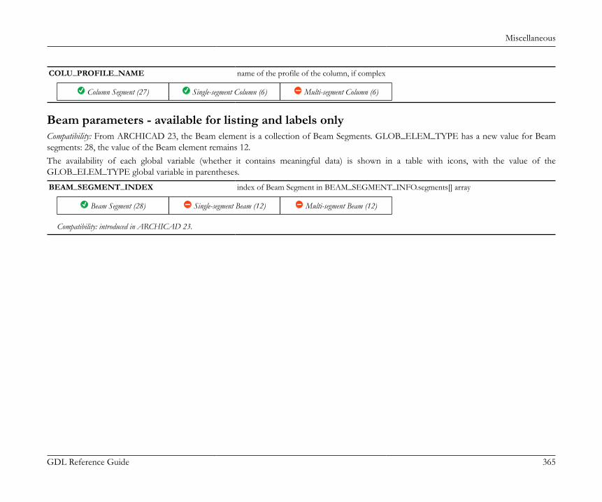
Miscellaneous
GDL Reference Guide 365
COLU_PROFILE_NAME name of the profile of the column, if complex
Column Segment (27) Single-segment Column (6) Multi-segment Column (6)
Beam parameters - available for listing and labels onlyCompatibility: From ARCHICAD 23, the Beam element is a collection of Beam Segments. GLOB_ELEM_TYPE has a new value for Beamsegments: 28, the value of the Beam element remains 12.The availability of each global variable (whether it contains meaningful data) is shown in a table with icons, with the value of theGLOB_ELEM_TYPE global variable in parentheses.
BEAM_SEGMENT_INDEX index of Beam Segment in BEAM_SEGMENT_INFO.segments[] array
Beam Segment (28) Single-segment Beam (12) Multi-segment Beam (12)
Compatibility: introduced in ARCHICAD 23.

Miscellaneous
GDL Reference Guide 366
BEAM_SEGMENT_INFO dictionary, contains all the Beam Segments' geometric settings which can determine the availabilityof other global variables, and further Beam Segment geometric data. Not available in parameterand property scripts.
When placed on a Beam Segment, BEAM_SEGMENT_INFO.segments[BEAM_SEGMENT_INDEX] contains the information about the labeled segment.• .segments[n].curvature: axis curvature (integer): 0 - straight, 1 - horizontally curved, 2 - vertically curved• .segments[n].tapered: (integer): 0 - uniform cross-section, 1 - tapered cross-section• .segments[n].refLineLength: 3D length of the beam segment reference line (length)• .segments[n].crossSection{}: (dictionary) cross-section data of segment• .segments[n].crossSection.type: (integer) cross-section type: 1 - rectangular, 2 - circular, 3 - complex profile• .segments[n].crossSection.startWidth: (length) bounding cross-section width of the start of the segment. The direction of the segment is defined by its
reference line.• .segments[n].crossSection.startHeight: (length) bounding cross-section height of the start of the segment. The direction of the segment is defined by
its reference line.• .segments[n].crossSection.endWidth: (length) bounding cross-section width of the end of the segment. The direction of the segment is defined by its reference
line.• .segments[n].crossSection.endHeight: (length) bounding cross-section height of the end of the segment. The direction of the segment is defined by its
reference line.
Beam Segment (28) Single-segment Beam (12) Multi-segment Beam (12)
Compatibility: introduced in ARCHICAD 23.
BEAM_THICKNESS thickness of the beam (0 in case of tapered beam segment)
Beam Segment (28) Single-segment Beam (12) Multi-segment Beam (12)
BEAM_HEIGHT height of the beam (0 in case of tapered beam segment)
Beam Segment (28) Single-segment Beam (12) Multi-segment Beam (12)
BEAM_REFLINE_OFFSET offset of the reference line relative to the axes of the beam
Beam Segment (28) Single-segment Beam (12) Multi-segment Beam (12)
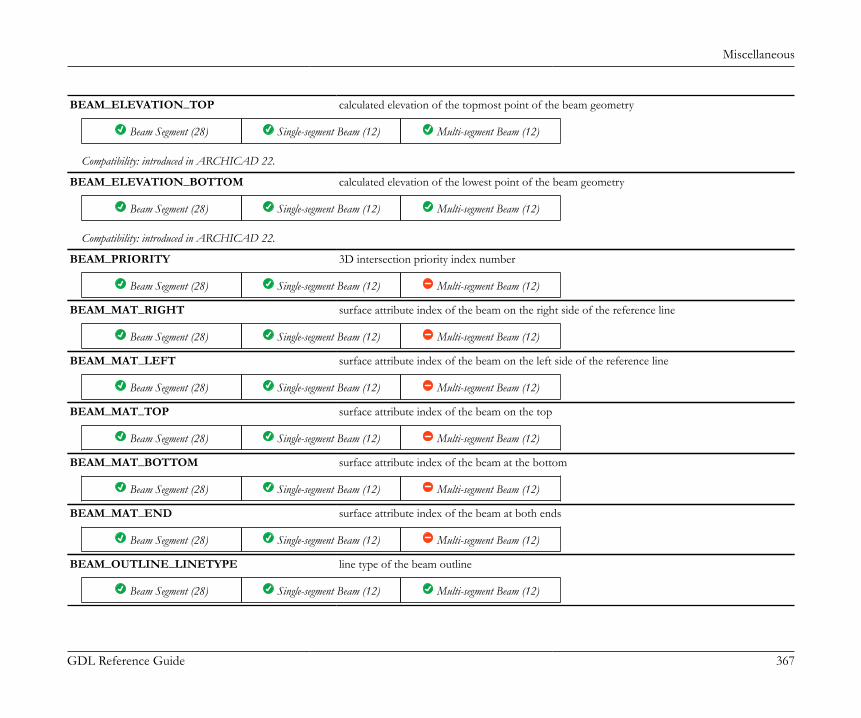
Miscellaneous
GDL Reference Guide 367
BEAM_ELEVATION_TOP calculated elevation of the topmost point of the beam geometry
Beam Segment (28) Single-segment Beam (12) Multi-segment Beam (12)
Compatibility: introduced in ARCHICAD 22.
BEAM_ELEVATION_BOTTOM calculated elevation of the lowest point of the beam geometry
Beam Segment (28) Single-segment Beam (12) Multi-segment Beam (12)
Compatibility: introduced in ARCHICAD 22.
BEAM_PRIORITY 3D intersection priority index number
Beam Segment (28) Single-segment Beam (12) Multi-segment Beam (12)
BEAM_MAT_RIGHT surface attribute index of the beam on the right side of the reference line
Beam Segment (28) Single-segment Beam (12) Multi-segment Beam (12)
BEAM_MAT_LEFT surface attribute index of the beam on the left side of the reference line
Beam Segment (28) Single-segment Beam (12) Multi-segment Beam (12)
BEAM_MAT_TOP surface attribute index of the beam on the top
Beam Segment (28) Single-segment Beam (12) Multi-segment Beam (12)
BEAM_MAT_BOTTOM surface attribute index of the beam at the bottom
Beam Segment (28) Single-segment Beam (12) Multi-segment Beam (12)
BEAM_MAT_END surface attribute index of the beam at both ends
Beam Segment (28) Single-segment Beam (12) Multi-segment Beam (12)
BEAM_OUTLINE_LINETYPE line type of the beam outline
Beam Segment (28) Single-segment Beam (12) Multi-segment Beam (12)

Miscellaneous
GDL Reference Guide 368
BEAM_AXES_LINETYPE line type of the beam axes
Beam Segment (28) Single-segment Beam (12) Multi-segment Beam (12)
BEAM_FILL fill type of the beam
Beam Segment (28) Single-segment Beam (12) Multi-segment Beam (12)
BEAM_BMAT_NAME building material name of the beam
Beam Segment (28) Single-segment Beam (12) Multi-segment Beam (12)
BEAM_BMAT building material index of the beam
Beam Segment (28) Single-segment Beam (12) Multi-segment Beam (12)
Compatibility: introduced in ARCHICAD 21.
BEAM_FILL_PEN pen of the beam fill
Beam Segment (28) Single-segment Beam (12) Multi-segment Beam (12)
BEAM_SECT_PEN pen of the contours of the beam cut surfaces
Beam Segment (28) Single-segment Beam (12) Multi-segment Beam (12)
BEAM_FBGD_PEN pen of the background of the fill of the beam
Beam Segment (28) Single-segment Beam (12) Multi-segment Beam (12)
BEAM_DIRECTION the direction of the beam reference line
Beam Segment (28) Single-segment Beam (12) Multi-segment Beam (12)
BEAM_POSITION absolute coordinates of the beam axis starting point
Beam Segment (28) Single-segment Beam (12) Multi-segment Beam (12)
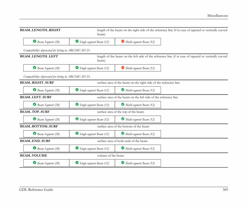
Miscellaneous
GDL Reference Guide 369
BEAM_LENGTH_RIGHT length of the beam on the right side of the reference line (0 in case of tapered or vertically curvedbeam)
Beam Segment (28) Single-segment Beam (12) Multi-segment Beam (12)
Compatibility: deprecated for listing in ARCHICAD 23.
BEAM_LENGTH_LEFT length of the beam on the left side of the reference line (0 in case of tapered or vertically curvedbeam)
Beam Segment (28) Single-segment Beam (12) Multi-segment Beam (12)
Compatibility: deprecated for listing in ARCHICAD 23.
BEAM_RIGHT_SURF surface area of the beam on the right side of the reference line
Beam Segment (28) Single-segment Beam (12) Multi-segment Beam (12)
BEAM_LEFT_SURF surface area of the beam on the left side of the reference line
Beam Segment (28) Single-segment Beam (12) Multi-segment Beam (12)
BEAM_TOP_SURF surface area of the top of the beam
Beam Segment (28) Single-segment Beam (12) Multi-segment Beam (12)
BEAM_BOTTOM_SURF surface area of the bottom of the beam
Beam Segment (28) Single-segment Beam (12) Multi-segment Beam (12)
BEAM_END_SURF surface area of both ends of the beam
Beam Segment (28) Single-segment Beam (12) Multi-segment Beam (12)
BEAM_VOLUME volume of the beam
Beam Segment (28) Single-segment Beam (12) Multi-segment Beam (12)
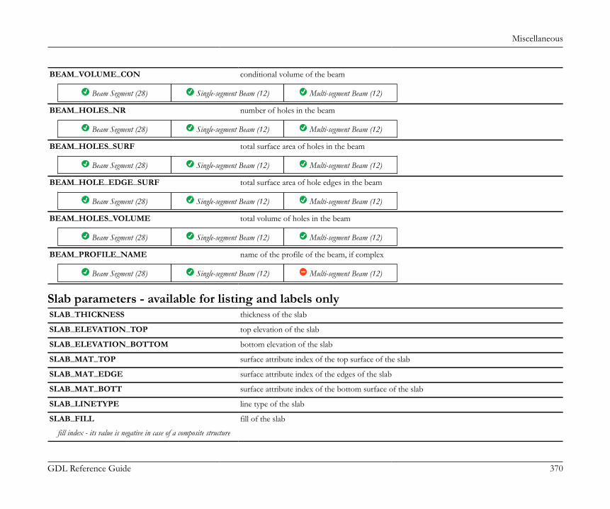
Miscellaneous
GDL Reference Guide 370
BEAM_VOLUME_CON conditional volume of the beam
Beam Segment (28) Single-segment Beam (12) Multi-segment Beam (12)
BEAM_HOLES_NR number of holes in the beam
Beam Segment (28) Single-segment Beam (12) Multi-segment Beam (12)
BEAM_HOLES_SURF total surface area of holes in the beam
Beam Segment (28) Single-segment Beam (12) Multi-segment Beam (12)
BEAM_HOLE_EDGE_SURF total surface area of hole edges in the beam
Beam Segment (28) Single-segment Beam (12) Multi-segment Beam (12)
BEAM_HOLES_VOLUME total volume of holes in the beam
Beam Segment (28) Single-segment Beam (12) Multi-segment Beam (12)
BEAM_PROFILE_NAME name of the profile of the beam, if complex
Beam Segment (28) Single-segment Beam (12) Multi-segment Beam (12)
Slab parameters - available for listing and labels onlySLAB_THICKNESS thickness of the slab
SLAB_ELEVATION_TOP top elevation of the slab
SLAB_ELEVATION_BOTTOM bottom elevation of the slab
SLAB_MAT_TOP surface attribute index of the top surface of the slab
SLAB_MAT_EDGE surface attribute index of the edges of the slab
SLAB_MAT_BOTT surface attribute index of the bottom surface of the slab
SLAB_LINETYPE line type of the slab
SLAB_FILL fill of the slab
fill index - its value is negative in case of a composite structure

Miscellaneous
GDL Reference Guide 371
SLAB_FILL_PEN pen of the fill of the slab
SLAB_FBGD_PEN pen of the background of the fill of the slab
SLAB_COMPS_NAME name of the composite structure of the slab
SLAB_BMAT_NAME building material name of the slab, empty string for composite slabs
SLAB_BMAT building material index of the slab, 0 for composite slabs
Compatibility: introduced in ARCHICAD 21.
SLAB_SKINS_NUMBER number of composite slab skins
range of 1 to 8, 0 if single fill applied
SLAB_SKINS_PARAMS parameters of the composite slab skins
array with 18 columns with arbitrary number of rows:• [1] fill• [2] thickness• [3] (old contour pen)• [4] pen of fill• [5] pen of fill background• [6] core status• [7] upper line pen• [8] upper line type• [9] lower line pen• [10] lower line type• [11] end face pen• [12] fill orientation• [13] skin type• [14] end face line type• [15] finish skin status• [16] oriented fill status• [17] core skin status (if no core skin exists, the thickest skin)• [18] building material index.core status: 0 - not part, 1 - part, 3 - last skin of core, fill orientation: 0 - global, 1 - local; skin type: in the current ARCHICAD always 0 - cut, it can be used as in wallslater; finish skin status: 0 not finish skin, 1: finish skin
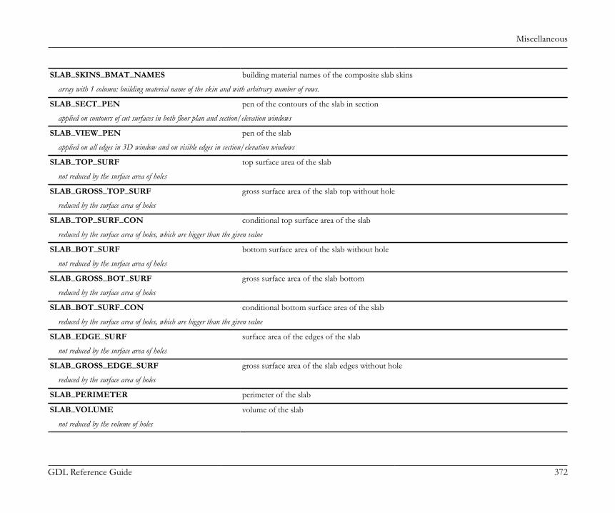
Miscellaneous
GDL Reference Guide 372
SLAB_SKINS_BMAT_NAMES building material names of the composite slab skins
array with 1 column: building material name of the skin and with arbitrary number of rows.
SLAB_SECT_PEN pen of the contours of the slab in section
applied on contours of cut surfaces in both floor plan and section/elevation windows
SLAB_VIEW_PEN pen of the slab
applied on all edges in 3D window and on visible edges in section/elevation windows
SLAB_TOP_SURF top surface area of the slab
not reduced by the surface area of holes
SLAB_GROSS_TOP_SURF gross surface area of the slab top without hole
reduced by the surface area of holes
SLAB_TOP_SURF_CON conditional top surface area of the slab
reduced by the surface area of holes, which are bigger than the given value
SLAB_BOT_SURF bottom surface area of the slab without hole
not reduced by the surface area of holes
SLAB_GROSS_BOT_SURF gross surface area of the slab bottom
reduced by the surface area of holes
SLAB_BOT_SURF_CON conditional bottom surface area of the slab
reduced by the surface area of holes, which are bigger than the given value
SLAB_EDGE_SURF surface area of the edges of the slab
not reduced by the surface area of holes
SLAB_GROSS_EDGE_SURF gross surface area of the slab edges without hole
reduced by the surface area of holes
SLAB_PERIMETER perimeter of the slab
SLAB_VOLUME volume of the slab
not reduced by the volume of holes

Miscellaneous
GDL Reference Guide 373
SLAB_GROSS_VOLUME gross volume of the slab without hole
reduced by the volume of holes
SLAB_VOLUME_CON conditional volume of the slab
reduced by the volume of holes, which are bigger than the given value
SLAB_SEGMENTS_NR number of segments of the slab
SLAB_HOLES_NR number of holes in the slab
SLAB_HOLES_AREA area of holes in the slab
SLAB_HOLES_PRM perimeter of holes in the slab
SLAB_GROSS_TOP_SURF_WITH_HOLES gross surface area of the slab top
SLAB_GROSS_BOT_SURF_WITH_HOLES gross surface area of the slab bottom
SLAB_GROSS_EDGE_SURF_WITH_HOLES gross surface area of the slab edges
SLAB_GROSS_VOLUME_WITH_HOLES gross volume of the slab
Stair component parameters
General stair variables - available for listing and labelsCompatibility: introduced in ARCHICAD 21.STAIR_AREA projected 2D area of the stair
2D 3D UI Parameter Property Default 0
STAIR_VOLUME area of the stair including all 3D parts
2D 3D UI Parameter Property Default 0
STAIR_HEIGHT difference between maximum and minimum of Z coordinates
2D 3D UI Parameter Property Default 0
STAIR_WALKLINE_LENGTH projected 2D length of the stair's walking line
2D 3D UI Parameter Property Default 0
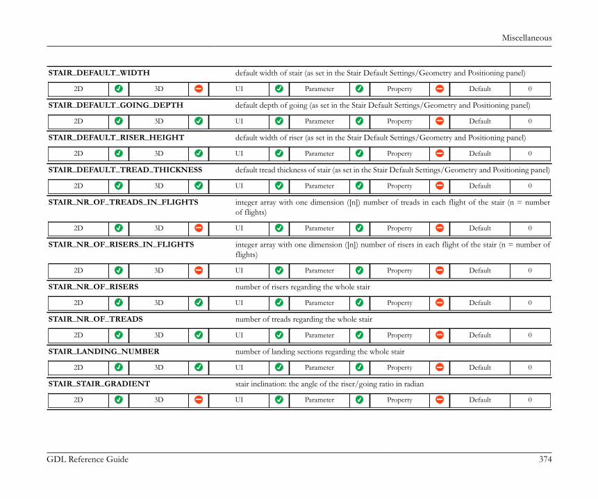
Miscellaneous
GDL Reference Guide 374
STAIR_DEFAULT_WIDTH default width of stair (as set in the Stair Default Settings/Geometry and Positioning panel)
2D 3D UI Parameter Property Default 0
STAIR_DEFAULT_GOING_DEPTH default depth of going (as set in the Stair Default Settings/Geometry and Positioning panel)
2D 3D UI Parameter Property Default 0
STAIR_DEFAULT_RISER_HEIGHT default width of riser (as set in the Stair Default Settings/Geometry and Positioning panel)
2D 3D UI Parameter Property Default 0
STAIR_DEFAULT_TREAD_THICKNESS default tread thickness of stair (as set in the Stair Default Settings/Geometry and Positioning panel)
2D 3D UI Parameter Property Default 0
STAIR_NR_OF_TREADS_IN_FLIGHTS integer array with one dimension ([n]) number of treads in each flight of the stair (n = numberof flights)
2D 3D UI Parameter Property Default 0
STAIR_NR_OF_RISERS_IN_FLIGHTS integer array with one dimension ([n]) number of risers in each flight of the stair (n = number offlights)
2D 3D UI Parameter Property Default 0
STAIR_NR_OF_RISERS number of risers regarding the whole stair
2D 3D UI Parameter Property Default 0
STAIR_NR_OF_TREADS number of treads regarding the whole stair
2D 3D UI Parameter Property Default 0
STAIR_LANDING_NUMBER number of landing sections regarding the whole stair
2D 3D UI Parameter Property Default 0
STAIR_STAIR_GRADIENT stair inclination: the angle of the riser/going ratio in radian
2D 3D UI Parameter Property Default 0
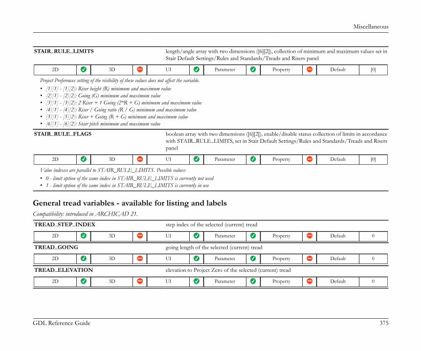
Miscellaneous
GDL Reference Guide 375
STAIR_RULE_LIMITS length/angle array with two dimensions ([6][2]), collection of minimum and maximum values set inStair Default Settings/Rules and Standards/Treads and Risers panel
2D 3D UI Parameter Property Default [0]
Project Preferences setting of the visibility of these values does not affect the variable.• [1][1] - [1][2]: Riser height (R) minimum and maximum value• [2][1] - [2][2]: Going (G) minimum and maximum value• [3][1] - [3][2]: 2 Riser + 1 Going (2*R + G) minimum and maximum value• [4][1] - [4][2]: Riser / Going ratio (R / G) minimum and maximum value• [5][1] - [5][2]: Riser + Going (R + G) minimum and maximum value• [6][1] - [6][2]: Stair pitch minimum and maximum value
STAIR_RULE_FLAGS boolean array with two dimensions ([6][2]), enable/disable status collection of limits in accordancewith STAIR_RULE_LIMITS, set in Stair Default Settings/Rules and Standards/Treads and Riserspanel
2D 3D UI Parameter Property Default [0]
Value indexes are parallel to STAIR_RULE_LIMITS. Possible values:• 0 - limit option of the same index in STAIR_RULE_LIMITS is currently not used• 1 - limit option of the same index in STAIR_RULE_LIMITS is currently in use
General tread variables - available for listing and labelsCompatibility: introduced in ARCHICAD 21.
TREAD_STEP_INDEX step index of the selected (current) tread
2D 3D UI Parameter Property Default 0
TREAD_GOING going length of the selected (current) tread
2D 3D UI Parameter Property Default 0
TREAD_ELEVATION elevation to Project Zero of the selected (current) tread
2D 3D UI Parameter Property Default 0
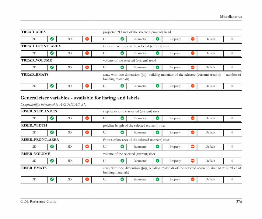
Miscellaneous
GDL Reference Guide 376
TREAD_AREA projected 2D area of the selected (current) tread
2D 3D UI Parameter Property Default 0
TREAD_FRONT_AREA front surface area of the selected (current) tread
2D 3D UI Parameter Property Default 0
TREAD_VOLUME volume of the selected (current) tread
2D 3D UI Parameter Property Default 0
TREAD_BMATS array with one dimension ([n]), building materials of the selected (current) tread (n = number ofbuilding materials)
2D 3D UI Parameter Property Default 0
General riser variables - available for listing and labelsCompatibility: introduced in ARCHICAD 21.
RISER_STEP_INDEX step index of the selected (current) riser
2D 3D UI Parameter Property Default 0
RISER_WIDTH polyline length of the selected (current) riser
2D 3D UI Parameter Property Default 0
RISER_FRONT_AREA front surface area of the selected (current) riser
2D 3D UI Parameter Property Default 0
RISER_VOLUME volume of the selected (current) riser
2D 3D UI Parameter Property Default 0
RISER_BMATS array with one dimension ([n]), building materials of the selected (current) riser (n = number ofbuilding materials)
2D 3D UI Parameter Property Default 0
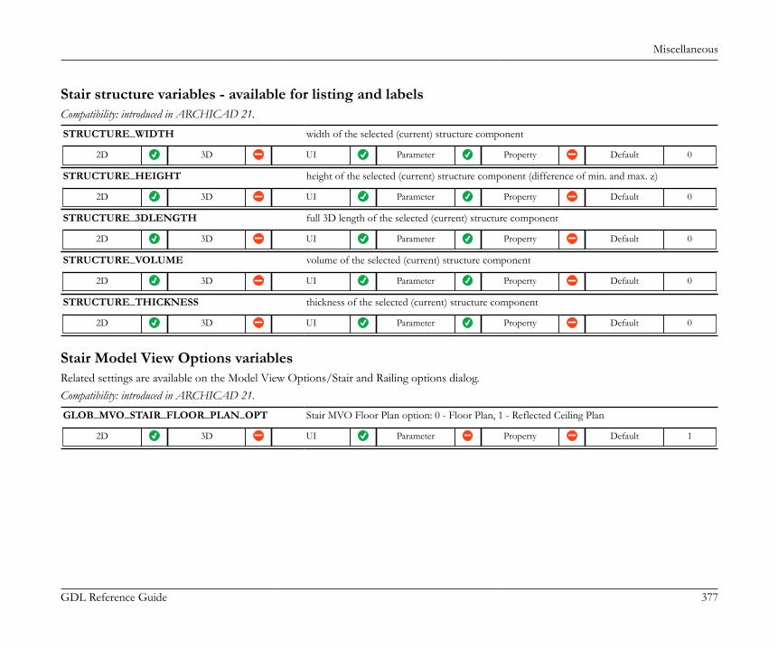
Miscellaneous
GDL Reference Guide 377
Stair structure variables - available for listing and labelsCompatibility: introduced in ARCHICAD 21.
STRUCTURE_WIDTH width of the selected (current) structure component
2D 3D UI Parameter Property Default 0
STRUCTURE_HEIGHT height of the selected (current) structure component (difference of min. and max. z)
2D 3D UI Parameter Property Default 0
STRUCTURE_3DLENGTH full 3D length of the selected (current) structure component
2D 3D UI Parameter Property Default 0
STRUCTURE_VOLUME volume of the selected (current) structure component
2D 3D UI Parameter Property Default 0
STRUCTURE_THICKNESS thickness of the selected (current) structure component
2D 3D UI Parameter Property Default 0
Stair Model View Options variablesRelated settings are available on the Model View Options/Stair and Railing options dialog.Compatibility: introduced in ARCHICAD 21.
GLOB_MVO_STAIR_FLOOR_PLAN_OPT Stair MVO Floor Plan option: 0 - Floor Plan, 1 - Reflected Ceiling Plan
2D 3D UI Parameter Property Default 1
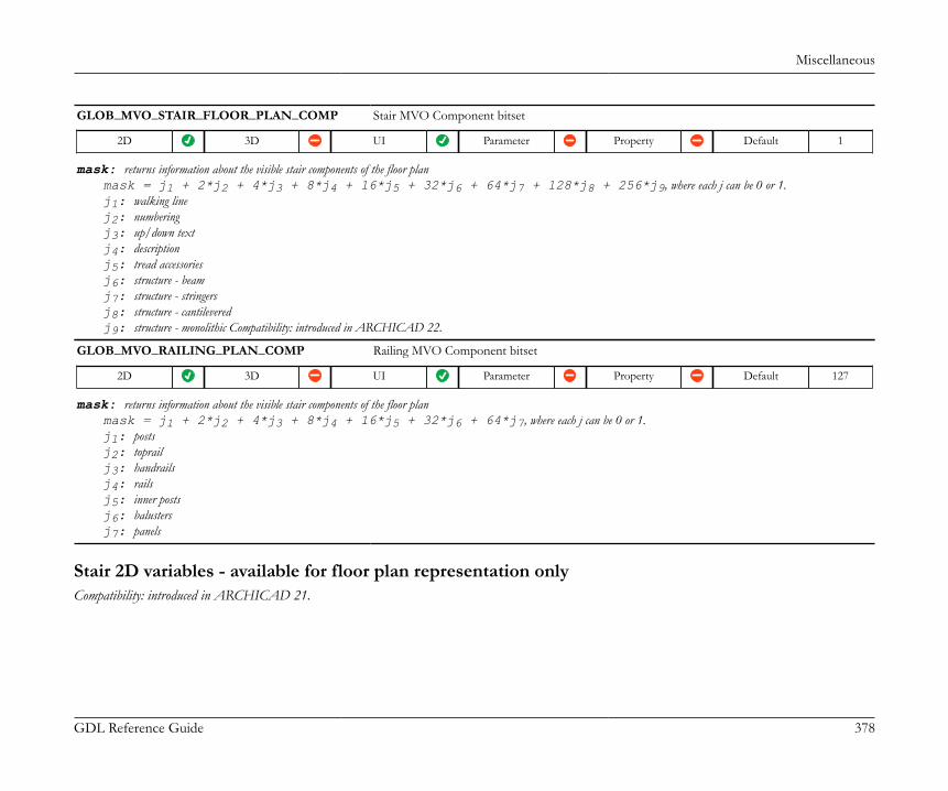
Miscellaneous
GDL Reference Guide 378
GLOB_MVO_STAIR_FLOOR_PLAN_COMP Stair MVO Component bitset
2D 3D UI Parameter Property Default 1
mask: returns information about the visible stair components of the floor planmask = j1 + 2*j2 + 4*j3 + 8*j4 + 16*j5 + 32*j6 + 64*j7 + 128*j8 + 256*j9, where each j can be 0 or 1.j1: walking linej2: numberingj3: up/down textj4: descriptionj5: tread accessoriesj6: structure - beamj7: structure - stringersj8: structure - cantileveredj9: structure - monolithic Compatibility: introduced in ARCHICAD 22.
GLOB_MVO_RAILING_PLAN_COMP Railing MVO Component bitset
2D 3D UI Parameter Property Default 127
mask: returns information about the visible stair components of the floor planmask = j1 + 2*j2 + 4*j3 + 8*j4 + 16*j5 + 32*j6 + 64*j7, where each j can be 0 or 1.j1: postsj2: toprailj3: handrailsj4: railsj5: inner postsj6: balustersj7: panels
Stair 2D variables - available for floor plan representation onlyCompatibility: introduced in ARCHICAD 21.
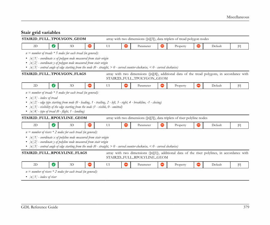
Miscellaneous
GDL Reference Guide 379
Stair grid variablesSTAIR2D_FULL_TPOLYGON_GEOM array with two dimensions ([n][3]), data triplets of tread polygon nodes
2D 3D UI Parameter Property Default [0]
n = number of treads * 5 nodes for each tread (in general):• [n][1] - coordinate x of polygon node measured from stair origin• [n][2] - coordinate y of polygon node measured from stair origin• [n][3] - central angle of edge starting from the node (0 - straight, > 0 - curved counter-clockwise, < 0 - curved clockwise)
STAIR2D_FULL_TPOLYGON_FLAGS array with two dimensions ([n][4]), additional data of the tread polygons, in accordance withSTAIR2D_FULL_TPOLYGON_GEOM
2D 3D UI Parameter Property Default [0]
n = number of treads * 5 nodes for each tread (in general):• [n][1] - index of tread• [n][2] - edge type starting from node (0 - leading, 1 - trailing, 2 - left, 3 - right, 4 - breakline, -1 - closing)• [n][3] - visibility of the edge starting from the node (1 - visible, 0 - omitted)• [n][4] - type of tread (0 - flight, 1 - landing)
STAIR2D_FULL_RPOLYLINE_GEOM array with two dimensions ([n][3]), data triplets of riser polyline nodes
2D 3D UI Parameter Property Default [0]
n = number of risers * 2 nodes for each tread (in general):• [n][1] - coordinate x of polyline node measured from stair origin• [n][2] - coordinate y of polyline node measured from stair origin• [n][3] - central angle of edge starting from the node (0 - straight, > 0 - curved counter-clockwise, < 0 - curved clockwise)
STAIR2D_FULL_RPOLYLINE_FLAGS array with two dimensions ([n][1]), additional data of the riser polylines, in accordance withSTAIR2D_FULL_RPOLYLINE_GEOM
2D 3D UI Parameter Property Default [0]
n = number of risers * 2 nodes for each tread (in general):• [n][1] - index of riser

Miscellaneous
GDL Reference Guide 380
STAIR2D_FULL_BOUNDARY_GEOM array with two dimensions ([n][3]), data triplets of stair boundary polygon nodes
2D 3D UI Parameter Property Default [0]
n = number of boundary nodes (5 in general):• [n][1] - coordinate x of polygon node measured from stair origin• [n][2] - coordinate y of polygon node measured from stair origin• [n][3] - central angle of edge starting from the node (0 - straight, > 0 - curved counter-clockwise, < 0 - curved clockwise)
The following globals are used to define the parts of the stair represented below the first breakmark.
STAIR2D_LOWER_TPOLYGON_GEOM array with two dimensions ([n][3]), data triplets of tread polygon nodes of lower part, similar toSTAIR2D_FULL_TPOLYGON_GEOM
2D 3D UI Parameter Property Default [0]
STAIR2D_LOWER_TPOLYGON_FLAGS array with two dimensions ([n][4]), additional data of tread polygon nodes of lower part, similar toSTAIR2D_FULL_TPOLYGON_FLAGS
2D 3D UI Parameter Property Default [0]
STAIR2D_LOWER_RPOLYLINE_GEOM array with two dimensions ([n][3]), data triplets of riser polyline nodes of lower part, similar toSTAIR2D_FULL_RPOLYLINE_GEOM
2D 3D UI Parameter Property Default [0]
STAIR2D_LOWER_RPOLYLINE_FLAGS array with two dimensions ([n][1]), additional data of riser polyline nodes of lower part, similar toSTAIR2D_FULL_RPOLYLINE_FLAGS
2D 3D UI Parameter Property Default [0]
STAIR2D_LOWER_BOUNDARY_GEOM array with two dimensions ([n][3]), data triplets of stair boundary polygon nodes of lower part,similar to STAIR2D_FULL_BOUNDARY_GEOM
2D 3D UI Parameter Property Default [0]
The following globals are used to define the parts of the stair represented between two breakmarks.
STAIR2D_MIDDLE_TPOLYGON_GEOM array with two dimensions ([n][3]), data triplets of tread polygon nodes of middle part, similar toSTAIR2D_FULL_TPOLYGON_GEOM
2D 3D UI Parameter Property Default [0]
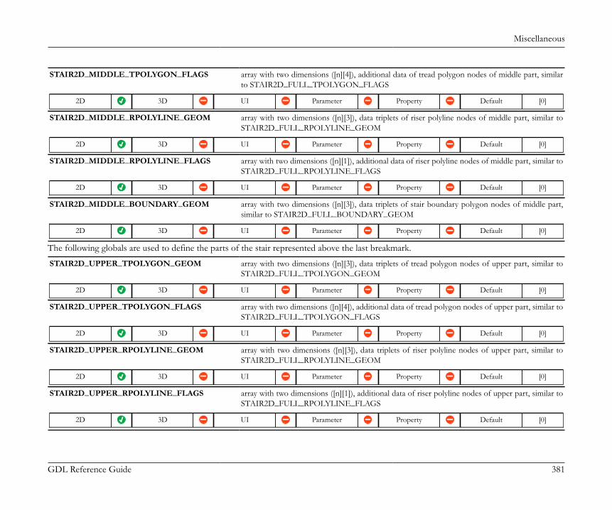
Miscellaneous
GDL Reference Guide 381
STAIR2D_MIDDLE_TPOLYGON_FLAGS array with two dimensions ([n][4]), additional data of tread polygon nodes of middle part, similarto STAIR2D_FULL_TPOLYGON_FLAGS
2D 3D UI Parameter Property Default [0]
STAIR2D_MIDDLE_RPOLYLINE_GEOM array with two dimensions ([n][3]), data triplets of riser polyline nodes of middle part, similar toSTAIR2D_FULL_RPOLYLINE_GEOM
2D 3D UI Parameter Property Default [0]
STAIR2D_MIDDLE_RPOLYLINE_FLAGS array with two dimensions ([n][1]), additional data of riser polyline nodes of middle part, similar toSTAIR2D_FULL_RPOLYLINE_FLAGS
2D 3D UI Parameter Property Default [0]
STAIR2D_MIDDLE_BOUNDARY_GEOM array with two dimensions ([n][3]), data triplets of stair boundary polygon nodes of middle part,similar to STAIR2D_FULL_BOUNDARY_GEOM
2D 3D UI Parameter Property Default [0]
The following globals are used to define the parts of the stair represented above the last breakmark.
STAIR2D_UPPER_TPOLYGON_GEOM array with two dimensions ([n][3]), data triplets of tread polygon nodes of upper part, similar toSTAIR2D_FULL_TPOLYGON_GEOM
2D 3D UI Parameter Property Default [0]
STAIR2D_UPPER_TPOLYGON_FLAGS array with two dimensions ([n][4]), additional data of tread polygon nodes of upper part, similar toSTAIR2D_FULL_TPOLYGON_FLAGS
2D 3D UI Parameter Property Default [0]
STAIR2D_UPPER_RPOLYLINE_GEOM array with two dimensions ([n][3]), data triplets of riser polyline nodes of upper part, similar toSTAIR2D_FULL_RPOLYLINE_GEOM
2D 3D UI Parameter Property Default [0]
STAIR2D_UPPER_RPOLYLINE_FLAGS array with two dimensions ([n][1]), additional data of riser polyline nodes of upper part, similar toSTAIR2D_FULL_RPOLYLINE_FLAGS
2D 3D UI Parameter Property Default [0]
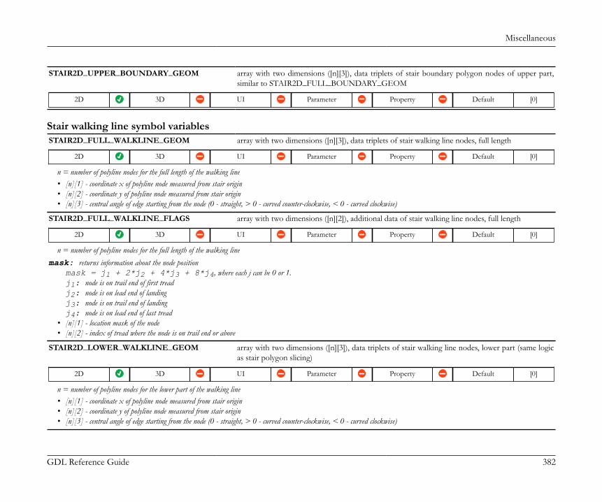
Miscellaneous
GDL Reference Guide 382
STAIR2D_UPPER_BOUNDARY_GEOM array with two dimensions ([n][3]), data triplets of stair boundary polygon nodes of upper part,similar to STAIR2D_FULL_BOUNDARY_GEOM
2D 3D UI Parameter Property Default [0]
Stair walking line symbol variablesSTAIR2D_FULL_WALKLINE_GEOM array with two dimensions ([n][3]), data triplets of stair walking line nodes, full length
2D 3D UI Parameter Property Default [0]
n = number of polyline nodes for the full length of the walking line• [n][1] - coordinate x of polyline node measured from stair origin• [n][2] - coordinate y of polyline node measured from stair origin• [n][3] - central angle of edge starting from the node (0 - straight, > 0 - curved counter-clockwise, < 0 - curved clockwise)
STAIR2D_FULL_WALKLINE_FLAGS array with two dimensions ([n][2]), additional data of stair walking line nodes, full length
2D 3D UI Parameter Property Default [0]
n = number of polyline nodes for the full length of the walking linemask: returns information about the node position
mask = j1 + 2*j2 + 4*j3 + 8*j4, where each j can be 0 or 1.j1: node is on trail end of first treadj2: node is on lead end of landingj3: node is on trail end of landingj4: node is on lead end of last tread
• [n][1] - location mask of the node• [n][2] - index of tread where the node is on trail end or above
STAIR2D_LOWER_WALKLINE_GEOM array with two dimensions ([n][3]), data triplets of stair walking line nodes, lower part (same logicas stair polygon slicing)
2D 3D UI Parameter Property Default [0]
n = number of polyline nodes for the lower part of the walking line• [n][1] - coordinate x of polyline node measured from stair origin• [n][2] - coordinate y of polyline node measured from stair origin• [n][3] - central angle of edge starting from the node (0 - straight, > 0 - curved counter-clockwise, < 0 - curved clockwise)

Miscellaneous
GDL Reference Guide 383
STAIR2D_LOWER_WALKLINE_FLAGS integer array with two dimensions ([n][2]), additional data of stair walking line nodes, lower part
2D 3D UI Parameter Property Default [0]
n = number of polyline nodes for the lower part of the walking linemask: returns information about the node position
mask = j1 + 2*j2 + 4*j3 + 8*j4, where each j can be 0 or 1.j1: node is on trail end of first treadj2: node is on lead end of landingj3: node is on trail end of landingj4: node is on lead end of last tread
• [n][1] - location mask of the node• [n][2] - index of tread where the node is on trail end or above
STAIR2D_MIDDLE_WALKLINE_GEOM array with two dimensions ([n][3]), data triplets of stair walking line nodes, middle part
2D 3D UI Parameter Property Default [0]
n = number of polyline nodes for the middle part of the walking line• [n][1] - coordinate x of polyline node measured from stair origin• [n][2] - coordinate y of polyline node measured from stair origin• [n][3] - central angle of edge starting from the node (0 - straight, > 0 - curved counter-clockwise, < 0 - curved clockwise)
STAIR2D_MIDDLE_WALKLINE_FLAGS integer array with two dimensions ([n][2]), additional data of stair walking line nodes, middle part
2D 3D UI Parameter Property Default [0]
n = number of polyline nodes for the middle part of the walking linemask: returns information about the node position
mask = j1 + 2*j2 + 4*j3 + 8*j4, where each j can be 0 or 1.j1: node is on trail end of first treadj2: node is on lead end of landingj3: node is on trail end of landingj4: node is on lead end of last tread
• [n][1] - location mask of the node• [n][2] - index of tread where the node is on trail end or above
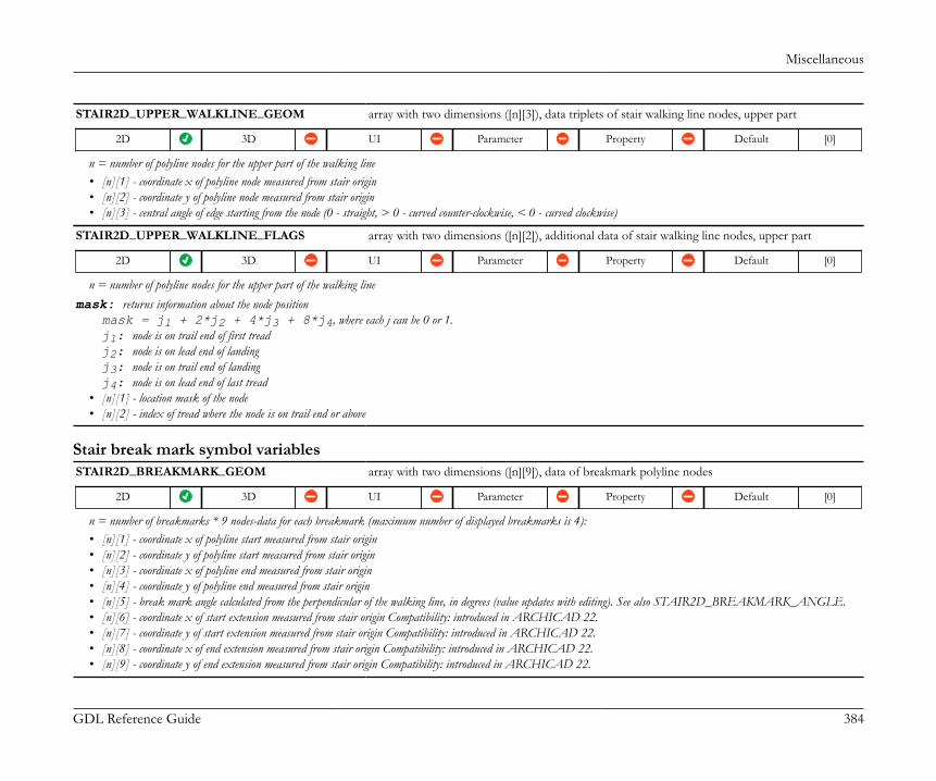
Miscellaneous
GDL Reference Guide 384
STAIR2D_UPPER_WALKLINE_GEOM array with two dimensions ([n][3]), data triplets of stair walking line nodes, upper part
2D 3D UI Parameter Property Default [0]
n = number of polyline nodes for the upper part of the walking line• [n][1] - coordinate x of polyline node measured from stair origin• [n][2] - coordinate y of polyline node measured from stair origin• [n][3] - central angle of edge starting from the node (0 - straight, > 0 - curved counter-clockwise, < 0 - curved clockwise)
STAIR2D_UPPER_WALKLINE_FLAGS array with two dimensions ([n][2]), additional data of stair walking line nodes, upper part
2D 3D UI Parameter Property Default [0]
n = number of polyline nodes for the upper part of the walking linemask: returns information about the node position
mask = j1 + 2*j2 + 4*j3 + 8*j4, where each j can be 0 or 1.j1: node is on trail end of first treadj2: node is on lead end of landingj3: node is on trail end of landingj4: node is on lead end of last tread
• [n][1] - location mask of the node• [n][2] - index of tread where the node is on trail end or above
Stair break mark symbol variablesSTAIR2D_BREAKMARK_GEOM array with two dimensions ([n][9]), data of breakmark polyline nodes
2D 3D UI Parameter Property Default [0]
n = number of breakmarks * 9 nodes-data for each breakmark (maximum number of displayed breakmarks is 4):• [n][1] - coordinate x of polyline start measured from stair origin• [n][2] - coordinate y of polyline start measured from stair origin• [n][3] - coordinate x of polyline end measured from stair origin• [n][4] - coordinate y of polyline end measured from stair origin• [n][5] - break mark angle calculated from the perpendicular of the walking line, in degrees (value updates with editing). See also STAIR2D_BREAKMARK_ANGLE.• [n][6] - coordinate x of start extension measured from stair origin Compatibility: introduced in ARCHICAD 22.• [n][7] - coordinate y of start extension measured from stair origin Compatibility: introduced in ARCHICAD 22.• [n][8] - coordinate x of end extension measured from stair origin Compatibility: introduced in ARCHICAD 22.• [n][9] - coordinate y of end extension measured from stair origin Compatibility: introduced in ARCHICAD 22.
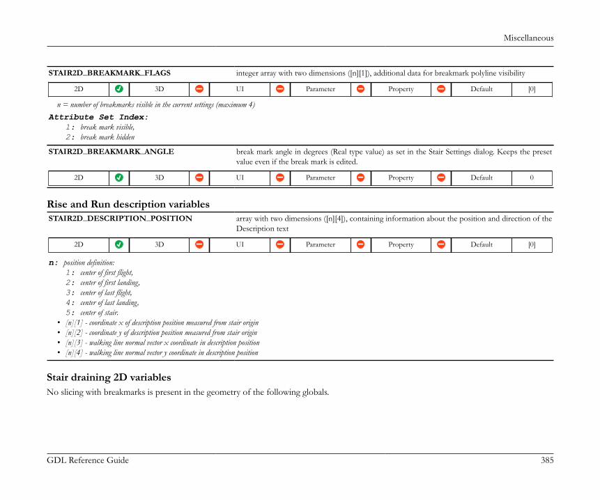
Miscellaneous
GDL Reference Guide 385
STAIR2D_BREAKMARK_FLAGS integer array with two dimensions ([n][1]), additional data for breakmark polyline visibility
2D 3D UI Parameter Property Default [0]
n = number of breakmarks visible in the current settings (maximum 4)Attribute Set Index:
1: break mark visible,2: break mark hidden
STAIR2D_BREAKMARK_ANGLE break mark angle in degrees (Real type value) as set in the Stair Settings dialog. Keeps the presetvalue even if the break mark is edited.
2D 3D UI Parameter Property Default 0
Rise and Run description variablesSTAIR2D_DESCRIPTION_POSITION array with two dimensions ([n][4]), containing information about the position and direction of the
Description text
2D 3D UI Parameter Property Default [0]
n: position definition:1: center of first flight,2: center of first landing,3: center of last flight,4: center of last landing,5: center of stair.
• [n][1] - coordinate x of description position measured from stair origin• [n][2] - coordinate y of description position measured from stair origin• [n][3] - walking line normal vector x coordinate in description position• [n][4] - walking line normal vector y coordinate in description position
Stair draining 2D variablesNo slicing with breakmarks is present in the geometry of the following globals.

Miscellaneous
GDL Reference Guide 386
STAIR2D_EXT_TPOLYGON_GEOM array with two dimensions ([n][3]), data triplets of extended tread polygon nodes (includingdraining). Similar structure as STAIR2D_FULL_TPOLYGON_GEOM.
2D 3D UI Parameter Property Default [0]
n = number of treads * 5 nodes for each tread (in general):• [n][1] - coordinate x of extended tread polygon node measured from stair origin• [n][2] - coordinate y of extended tread polygon node measured from stair origin• [n][3] - central angle of edge starting from the node (0 - straight, > 0 - curved counter-clockwise, < 0 - curved clockwise)
STAIR2D_EXT_TPOLYGON_FLAGS array with two dimensions ([n][4]), additional data of the tread extendedpolygons, in accordance with STAIR2D_EXT_TPOLYGON_GEOM. Similar structure asSTAIR2D_FULL_TPOLYGON_FLAGS.
2D 3D UI Parameter Property Default [0]
n = number of treads * 5 nodes for each tread (in general):• [n][1] - index of tread• [n][2] - edge type starting from node (0 - leading, 1 - trailing, 2 - left, 3 - right, -1 - closing)• [n][3] - visibility of the edge starting from the node (1 - visible, 0 - omitted)• [n][4] - type of tread (0 - flight, 1 - landing)
STAIR2D_EXT_RPOLYLINE_GEOM array with two dimensions ([n][3]), data triplets of extended riser polyline nodes (including draining).Similar structure as STAIR2D_FULL_RPOLYLINE_GEOM.
2D 3D UI Parameter Property Default [0]
n = number of risers * 2 nodes for each tread (in general):• [n][1] - coordinate x of polyline node measured from stair origin• [n][2] - coordinate y of polyline node measured from stair origin• [n][3] - central angle of edge starting from the node (0 - straight, > 0 - curved counter-clockwise, < 0 - curved clockwise)
STAIR2D_EXT_RPOLYLINE_FLAGS array with two dimensions ([n][1]), additional data of the riser polylines,in accordance with STAIR2D_EXT_RPOLYLINE_GEOM. Similar structure asSTAIR2D_FULL_RPOLYLINE_FLAGS.
2D 3D UI Parameter Property Default [0]
n = number of risers * 2 nodes for each tread (in general):• [n][1] - index of riser
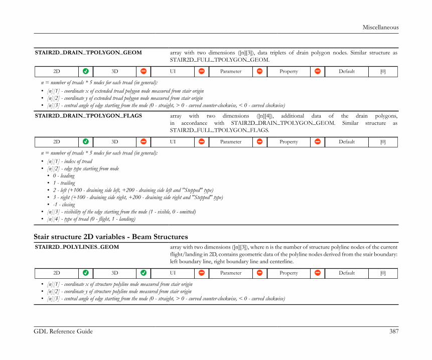
Miscellaneous
GDL Reference Guide 387
STAIR2D_DRAIN_TPOLYGON_GEOM array with two dimensions ([n][3]), data triplets of drain polygon nodes. Similar structure asSTAIR2D_FULL_TPOLYGON_GEOM.
2D 3D UI Parameter Property Default [0]
n = number of treads * 5 nodes for each tread (in general):• [n][1] - coordinate x of extended tread polygon node measured from stair origin• [n][2] - coordinate y of extended tread polygon node measured from stair origin• [n][3] - central angle of edge starting from the node (0 - straight, > 0 - curved counter-clockwise, < 0 - curved clockwise)
STAIR2D_DRAIN_TPOLYGON_FLAGS array with two dimensions ([n][4]), additional data of the drain polygons,in accordance with STAIR2D_DRAIN_TPOLYGON_GEOM. Similar structure asSTAIR2D_FULL_TPOLYGON_FLAGS.
2D 3D UI Parameter Property Default [0]
n = number of treads * 5 nodes for each tread (in general):• [n][1] - index of tread• [n][2] - edge type starting from node
• 0 - leading• 1 - trailing• 2 - left (+100 - draining side left, +200 - draining side left and "Stepped" type)• 3 - right (+100 - draining side right, +200 - draining side right and "Stepped" type)• -1 - closing
• [n][3] - visibility of the edge starting from the node (1 - visible, 0 - omitted)• [n][4] - type of tread (0 - flight, 1 - landing)
Stair structure 2D variables - Beam StructuresSTAIR2D_POLYLINES_GEOM array with two dimensions ([n][3]), where n is the number of structure polyline nodes of the current
flight/landing in 2D, contains geometric data of the polyline nodes derived from the stair boundary:left boundary line, right boundary line and centerline.
2D 3D UI Parameter Property Default [0]
• [n][1] - coordinate x of structure polyline node measured from stair origin• [n][2] - coordinate y of structure polyline node measured from stair origin• [n][3] - central angle of edge starting from the node (0 - straight, > 0 - curved counter-clockwise, < 0 - curved clockwise)

Miscellaneous
GDL Reference Guide 388
STAIR2D_POLYLINES_FLAGS array with two dimensions ([n][1]), where n is the number of structure polyline nodes of the currentflight/landing in 2D, contains group data of the polyline nodes.
2D 3D UI Parameter Property Default [0]
• [n][1] - position flags, point n belongs to: 0 - left boundary, 1 - right boundary, 2 - center line
STAIR2D_STRUCT_ATTRIBUTES array with two dimensions ([2][7]), containing attributes settings of the visible ([1][n]) and invisible([2][n]) parts of the structure.
2D 3D UI Parameter Property Default [0, 0, 0,0, 0, 0, 0]
• [n][1] - boundary line type index• [n][2] - boundary pen index• [n][3] - symbol fill type• [n][4] - symbol fill pen• [n][5] - symbol fill background pen• [n][6] - symbol fill ON/OFF boolean control for Custom display only (STAIR2D_CUSTOMDISPLAY = 1)• [n][7] - symbol part enable ON/OFF boolean control for Custom display only (STAIR2D_CUSTOMDISPLAY = 1).
Stair structure 2D variables - Monolithic StructureCompatibility: introduced in ARCHICAD 22.These globals are filled with values with respect to actual Floor Plan/Reflected Ceiling Plan View.
STAIR2D_FULL_SPOLYGON_GEOM array with two dimensions ([n][3]), containing sub-polygons of the stair 2D projection.
2D 3D UI Parameter Property Default [0]
• [n][1] - coordinate x of structure polygon node measured from stair origin• [n][2] - coordinate y of structure polygon node measured from stair origin• [n][3] - central angle of edge starting from the node (0 - straight, > 0 - curved counter-clockwise, < 0 - curved clockwise)
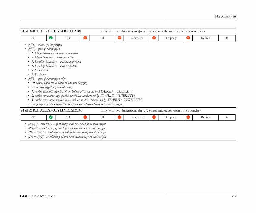
Miscellaneous
GDL Reference Guide 389
STAIR2D_FULL_SPOLYGON_FLAGS array with two dimensions ([n][2]), where n is the number of polygon nodes.
2D 3D UI Parameter Property Default [0]
• [n][1] - index of sub-polygon• [n][2] - type of sub-polygon
• 1: Flight boundary - without connection• 2: Flight boundary - with connection• 3: Landing boundary - without connection• 4: Landing boundary - with connection• 5: Connection• 6: Draining
• [n][3] - type of sub-polygon edge• -1: closing point (next point is new sub-polygon)• 0: invisible edge (only bounds area)• 1: visible monolith edge (visible or hidden attribute set by STAIR2D_VISIBILITY)• 2: visible connection edge (visible or hidden attribute set by STAIR2D_VISIBILITY)• 3: visible connection detail edge (visible or hidden attribute set by STAIR2D_VISIBILITY)A sub-polygon of type Connection can have mixed monolith and connection edges.
STAIR2D_FULL_SPOLYLINE_GEOM array with two dimensions ([n][2]), containing edges within the boundary.
2D 3D UI Parameter Property Default [0]
• [2*i][1] - coordinate x of starting node measured from stair origin• [2*i][2] - coordinate y of starting node measured from stair origin• [2*i + 1][1] - coordinate x of end node measured from stair origin• [2*i + 1][2] - coordinate y of end node measured from stair origin

Miscellaneous
GDL Reference Guide 390
STAIR2D_FULL_SPOLYLINE_FLAGS array with one dimension [n], where n is the number of nodes inSTAIR2D_FULL_SPOLYLINE_GEOM.
2D 3D UI Parameter Property Default [0]
• [n] - type of edge• 1: Going, cut with drain• 2: Going, full• 3: Going Nosing (slanted risers), cut with drain• 4: Going Nosing (slanted risers), full• 5: Landing Line, cut with drain• 6: Landing Line, full• 7: Connection• 8: Connection Detail• 9: Draining (stepped draining)• 10: Draining Nosing (draining with slanted steps)

Miscellaneous
GDL Reference Guide 391
STAIR2D_MONOLITH_ATTRIBUTES array with two dimensions ([2][23]), containing attributes and visibility settings of the visible ([1][n])and invisible ([2][n]) parts of the monolithic structure.
2D 3D UI Parameter Property Default [0]
• [n][1] - Structure visibility (bool)• [n][2] - Draining visibility (bool)• [n][3] - Contour line type• [n][4] - Contour line pen• [n][5] - Structure Going visibility (bool)• [n][6] - Landing Line visibility (bool)• [n][7] - Going Line Type• [n][8] - Going Line Pen• [n][9] - Structure Going Nosing visibility (bool)• [n][10] - Going Nosing line type• [n][11] - Going Nosing line pen• [n][12] - Connection visibility (bool)• [n][13] - Connection line type• [n][14] - Connection line pen• [n][15] - Connection Detail line type• [n][16] - Connection Detail line pen• [n][17] - Draining Fill and Structure Fill visibility (bool)• [n][18] - Structure fill type• [n][19] - Structure fill pen• [n][20] - Structure fill background pen• [n][21] - Draining fill type• [n][22] - Draining fill pen• [n][23] - Draining fill background pen
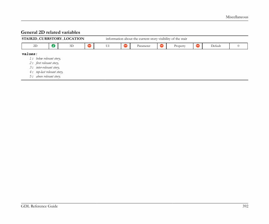
Miscellaneous
GDL Reference Guide 392
General 2D related variablesSTAIR2D_CURRSTORY_LOCATION information about the current story visibility of the stair
2D 3D UI Parameter Property Default 0
values:1: below relevant story,2: first relevant story,3: inter-relevant story,4: top-last relevant story,5: above relevant story.
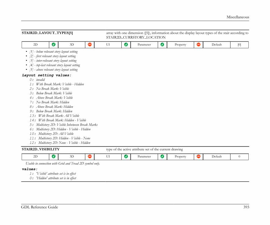
Miscellaneous
GDL Reference Guide 393
STAIR2D_LAYOUT_TYPES[5] array with one dimension ([5]), information about the display layout types of the stair according toSTAIR2D_CURRSTORY_LOCATION
2D 3D UI Parameter Property Default [0]
• [1] - below relevant story layout setting• [2] - first relevant story layout setting• [3] - inter-relevant story layout setting• [4] - top-last relevant story layout setting• [5] - above relevant story layout setting
Layout setting values:0: invalid1: With Break Mark: Visible - Hidden2: No Break Mark: Visible3: Below Break Mark: Visible4: Above Break Mark: Visible7: No Break Mark: Hidden8: Above Break Mark: Hidden9: Below Break Mark: Hidden13: With Break Mark: All Visible14: With Break Mark: Hidden - Visible5: Multistory 2D: Visible Inbetween Break Marks6: Multistory 2D: Hidden - Visible - Hidden10: Multistory 2D: All Visible11: Multistory 2D: Hidden - Visible - None12: Multistory 2D: None - Visible - Hidden
STAIR2D_VISIBILITY type of the active attribute set of the current drawing
2D 3D UI Parameter Property Default 0
Usable in connection with Grid and Tread 2D symbol only.values:
1: 'Visible' attribute set is in effect0: 'Hidden' attribute set is in effect
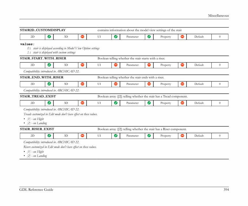
Miscellaneous
GDL Reference Guide 394
STAIR2D_CUSTOMDISPLAY contains information about the model view settings of the stair
2D 3D UI Parameter Property Default 0
values:0: stair is displayed according to Model View Option settings1: stair is displayed with custom settings
STAIR_START_WITH_RISER Boolean telling whether the stair starts with a riser.
2D 3D UI Parameter Property Default 0
Compatibility: introduced in ARCHICAD 22.
STAIR_END_WITH_RISER Boolean telling whether the stair ends with a riser.
2D 3D UI Parameter Property Default 0
Compatibility: introduced in ARCHICAD 22.
STAIR_TREAD_EXIST Boolean array ([2]) telling whether the stair has a Tread component.
2D 3D UI Parameter Property Default 0
Compatibility: introduced in ARCHICAD 22.Treads customized in Edit mode don't have effect on these values.• [1] - on Flight• [2] - on Landing
STAIR_RISER_EXIST Boolean array ([2]) telling whether the stair has a Riser component.
2D 3D UI Parameter Property Default 0
Compatibility: introduced in ARCHICAD 22.Risers customized in Edit mode don't have effect on these values.• [1] - on Flight• [2] - on Landing
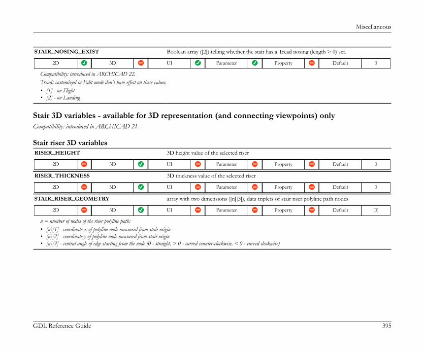
Miscellaneous
GDL Reference Guide 395
STAIR_NOSING_EXIST Boolean array ([2]) telling whether the stair has a Tread nosing (length > 0) set.
2D 3D UI Parameter Property Default 0
Compatibility: introduced in ARCHICAD 22.Treads customized in Edit mode don't have effect on these values.• [1] - on Flight• [2] - on Landing
Stair 3D variables - available for 3D representation (and connecting viewpoints) onlyCompatibility: introduced in ARCHICAD 21.
Stair riser 3D variablesRISER_HEIGHT 3D height value of the selected riser
2D 3D UI Parameter Property Default 0
RISER_THICKNESS 3D thickness value of the selected riser
2D 3D UI Parameter Property Default 0
STAIR_RISER_GEOMETRY array with two dimensions ([n][3]), data triplets of stair riser polyline path nodes
2D 3D UI Parameter Property Default [0]
n = number of nodes of the riser polyline path:• [n][1] - coordinate x of polyline node measured from stair origin• [n][2] - coordinate y of polyline node measured from stair origin• [n][3] - central angle of edge starting from the node (0 - straight, > 0 - curved counter-clockwise, < 0 - curved clockwise)

Miscellaneous
GDL Reference Guide 396
RISER_CUT array with two dimensions ([2][2]), contains data of starting and closing points of the ideal TUBE(modelling the riser in 3D)
2D 3D UI Parameter Property Default [0]
The display segmentation of the tube does not affect the value of this variable. To achieve a correct model in all cases, this global can be used to calculate the actual starting andclosing points of the tube following the segmented arc.• [1][1] - coordinate x of starting node measured from stair origin• [1][2] - coordinate y of starting node measured from stair origin• [2][1] - coordinate x of closing node measured from stair origin• [2][2] - coordinate y of closing node measured from stair origin
RISER_SLANT_ANGLE slant angle of the selected riser
2D 3D UI Parameter Property Default 0
In case Slanting is set to 0, the value of this global is 90 degrees.
Stair tread 2D-3D variablesTREAD_THICKNESS 3D thickness value of the selected tread
2D 3D UI Parameter Property Default 0
STAIR_TREAD_GEOMETRY array with two dimensions ([n][3]), data triplets of stair tread polygon nodes
2D 3D UI Parameter Property Default [0]
n = number of nodes of the tread polygon:• [n][1] - coordinate x of node measured from stair origin• [n][2] - coordinate y of node measured from stair origin• [n][3] - central angle of edge starting from the node (0 - straight, > 0 - curved counter-clockwise, < 0 - curved clockwise)

Miscellaneous
GDL Reference Guide 397
STAIR_TREAD_FLAGS array with two dimensions ([n][1]), additional data of the tread polygon edges (starting from nodes),in accordance with STAIR_TREAD_GEOMETRY
2D 3D UI Parameter Property Default [0]
n = number of nodes of the tread polygon:• [n][1] - flag of the nth edge of the polygon
flags:0: lead edge of tread polygon1: trail edge of tread polygon2: left edge of tread polygon3: right edge of tread polygon-1: closing node of tread polygon
TREAD_LOWER_RISER_THICKNESS thickness of the riser below the current tread (measured between grid and structure)
2D 3D UI Parameter Property Default 0
TREAD_LOWER_RISER_HEIGHT height of the riser below the current tread (measured between the bottom plane of the current treadand the upper plane of the previous tread)
2D 3D UI Parameter Property Default 0
TREAD_LOWER_RISER_SLANT_ANGLE slant angle of the riser below the current tread in degrees (is Slanting = 0, the value is 90 degrees)
2D 3D UI Parameter Property Default 0
TREAD_UPPER_RISER_THICKNESS thickness of the riser above the current tread (measured between grid and structure)
2D 3D UI Parameter Property Default 0
TREAD_UPPER_RISER_HEIGHT height of the riser above the current tread (measured between the top plane of the current treadand the bottom plane of the following tread)
2D 3D UI Parameter Property Default 0
TREAD_UPPER_RISER_SLANT_ANGLE slant angle of the riser above the current tread in degrees (is Slanting = 0, the value is 90 degrees)
2D 3D UI Parameter Property Default 0
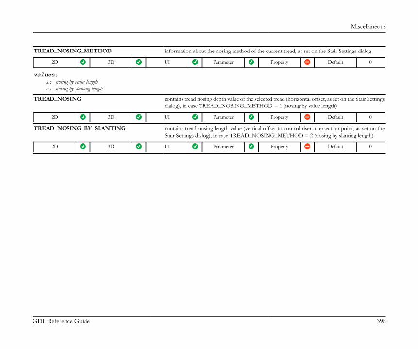
Miscellaneous
GDL Reference Guide 398
TREAD_NOSING_METHOD information about the nosing method of the current tread, as set on the Stair Settings dialog
2D 3D UI Parameter Property Default 0
values:1: nosing by value length2: nosing by slanting length
TREAD_NOSING contains tread nosing depth value of the selected tread (horizontal offset, as set on the Stair Settingsdialog), in case TREAD_NOSING_METHOD = 1 (nosing by value length)
2D 3D UI Parameter Property Default 0
TREAD_NOSING_BY_SLANTING contains tread nosing length value (vertical offset to control riser intersection point, as set on theStair Settings dialog), in case TREAD_NOSING_METHOD = 2 (nosing by slanting length)
2D 3D UI Parameter Property Default 0

Miscellaneous
GDL Reference Guide 399
Stair structure variablesSTAIR_STRUCTURE_GEOMETRY array with two dimensions ([n][14]), where n is the number of structure polygons points of the
current flight/landing.
2D 3D UI Parameter Property Default [0]
• [n][1] - coordinate x of structure polygon node n, measured from stair origin• [n][2] - coordinate y of structure polygon node n, measured from stair origin• [n][3] - coordinate z of structure polygon node n, measured from stair origin• [n][4] - central angle in degrees of the edge starting from node n (0 - straight edge, < 0 - arc, counter-clockwise, > 0 - arc, clockwise)• [n][5] - riser slant angle of the edge starting from node n. In case of leading edge, the angle belongs to the riser below the polygon. In case of trailing edge, the angle belongs to the
riser above the polygon. Contains 0 for all other edge categories.• [n][6] - height of the riser below the structure polygon (returns 0 in case there is no riser, or if the polygon is a connection polygon)• [n][7] - height of the riser above the structure polygon (returns 0 in case there is no riser, or if the polygon is a connection polygon)• [n][8] - thickness of the tread of the structure polygon (returns 0 if the polygon is a connection polygon)• [n][9] - thickness of the gap below the tread of the structure polygon (returns 0 if the polygon is a connection polygon)• [n][10-14] - Compatibility: introduced in ARCHICAD 22.• [n][10] - Cantilevered structure height (read from its ac_stairStructureThickness parameter) beneath the tread at this point. Zero in case of connection polygons.• [n][11] - Tread nosing at the edge starting from this point.
• Zero in case of connection polygons• Nosing of the tread above leading edges• Nosing of the next tread above trailing edges• Zero in case of other edges
• [n][12] - Riser thickness at the edge starting from this point.• Zero in case of connection polygons• Thickness of the riser below leading edges• Thickness of the riser above trailing edges• Zero in case of other edges
• [n][13] - Riser gap thickness at the edge starting from this point.• Zero in case of connection polygons• Gap thickness of the riser below leading edges• Gap thickness of the riser above trailing edges• Zero in case of other edges
• [n][14] - Cantilevered structure horizontal thickness (read from its ac_stairStructureHorizThick parameter) at the edge starting from this point.• Zero in case of connection polygons• Horizontal thickness of the cantilevered structure below leading edges• Horizontal thickness of the cantilevered structure above trailing edges• Zero in case of other edges

Miscellaneous
GDL Reference Guide 400
STAIR_STRUCTURE_FLAGS array with two dimensions ([n][3]), where n is the number of structure polygons points of the currentflight/landing.
2D 3D UI Parameter Property Default [0]
• [n][1] - polygon type of node n in the structure polygon: core or connection polygon• [n][2] - indicates which side node n belongs to: left or right structure polygon where the divide is the centerline of the stair: 0 - left, 1 - right• [n][3] - type of edge starting from node n. Possible values: 0 - leading edge, 1 - trailing edge, 2 - left edge, 3 - right edge, 4 - centerline edge, -1 - end edge.
values: indicators of node categories for [n][1]-1: No Connection (Whole Tread) Polygon: in case of landing, all points are in this category. No such value in case of flight polygons.0: No Connection (Core) Polygon: in case of landing, start-end connections may affect the geometry. In case of flight, the polygon is always complete.1: Start Connection Polygon: indicates the leftover polygon, or the enclosed polygon between core and connection polygons. Nodes necessary to define beam-path: startpoint orendpoint with boundary polygon points.2: Start Connection Position Polygon: indicates the position of the connection. This polygon is always a generic unit polygon, not part of beam-path, and only necessary for thecutting plane and end plate position.3: Start Connection Break Polygon: indicates the polygon containing the breakpoints in case of a vertical or horizontal connection. Points necessary for beam-path: startpointor endpoint completed with boundary polygon points.4: Start Connection Direction Polygon: indicates the polygon needed to do the bisector cut in case of a bisector connection. This polygon is always a generic unit polygon, notpart of beam-path, and only necessary to get the cutting plane position.5: Start Connection Extension Polygon: indicates points of beam extension to support cuttings. Points necessary for beam-path: startpoint or endpoint completed with boundarypolygon points.6: Start Connection Structure Border Polygon: indicates the beam-boundary points at start. This polygon is always a generic unit polygon. Points necessary for beam-path:startpoint or endpoint.101: End Connection Polygon: indicates the leftover polygon, or the enclosed polygon between core and connection polygons. Nodes necessary to define beam-path: startpointor endpoint with boundary polygon points.102: End Connection Position Polygon: indicates the position of the connection. This polygon is always a generic unit polygon, not part of beam-path, and only necessary forthe cutting plane and end plate position.103: End Connection Break Polygon: indicates the polygon containing the breakpoints in case of a vertical or horizontal connection. Points necessary for beam-path: startpointor endpoint completed with boundary polygon points.104: End Connection Direction Polygon: indicates the polygon needed to do the bisector cut in case of a bisector connection. This polygon is always a generic unit polygon, notpart of beam-path, and only necessary to get the cutting plane position.105: End Connection Extension Polygon: indicates points of beam extension to support cuttings. Points necessary for beam-path: startpoint or endpoint completed with boundarypolygon points.106: End Connection Structure Border Polygon: indicates the beam-boundary points at end. This polygon is always a generic unit polygon. Points necessary for beam-path:startpoint or endpoint.
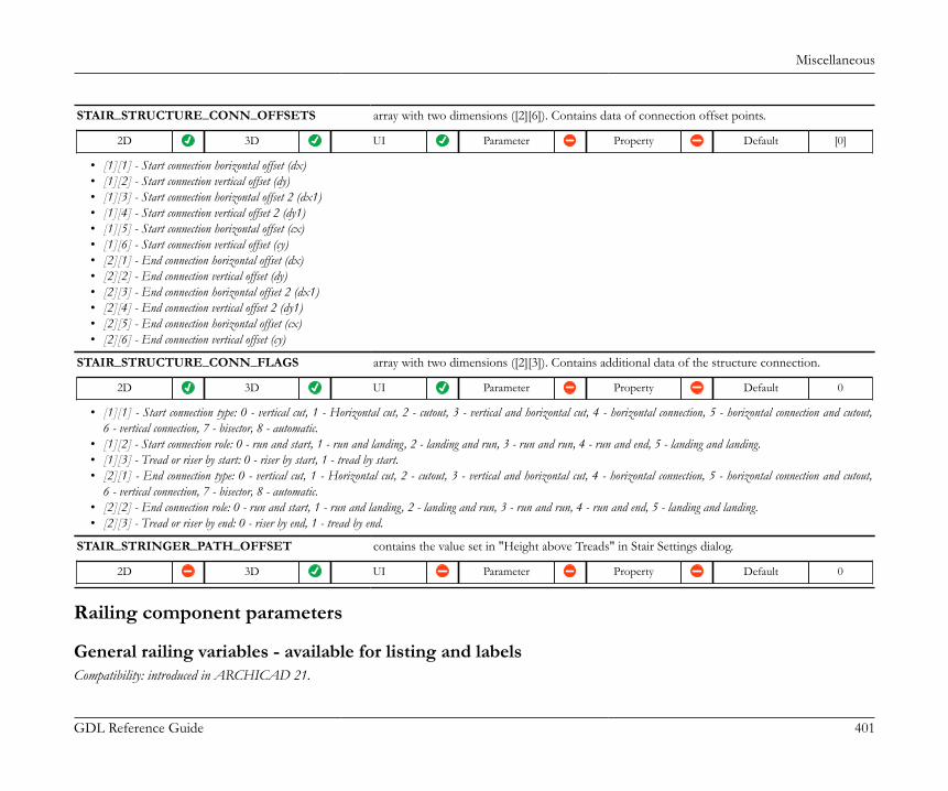
Miscellaneous
GDL Reference Guide 401
STAIR_STRUCTURE_CONN_OFFSETS array with two dimensions ([2][6]). Contains data of connection offset points.
2D 3D UI Parameter Property Default [0]
• [1][1] - Start connection horizontal offset (dx)• [1][2] - Start connection vertical offset (dy)• [1][3] - Start connection horizontal offset 2 (dx1)• [1][4] - Start connection vertical offset 2 (dy1)• [1][5] - Start connection horizontal offset (cx)• [1][6] - Start connection vertical offset (cy)• [2][1] - End connection horizontal offset (dx)• [2][2] - End connection vertical offset (dy)• [2][3] - End connection horizontal offset 2 (dx1)• [2][4] - End connection vertical offset 2 (dy1)• [2][5] - End connection horizontal offset (cx)• [2][6] - End connection vertical offset (cy)
STAIR_STRUCTURE_CONN_FLAGS array with two dimensions ([2][3]). Contains additional data of the structure connection.
2D 3D UI Parameter Property Default 0
• [1][1] - Start connection type: 0 - vertical cut, 1 - Horizontal cut, 2 - cutout, 3 - vertical and horizontal cut, 4 - horizontal connection, 5 - horizontal connection and cutout,6 - vertical connection, 7 - bisector, 8 - automatic.
• [1][2] - Start connection role: 0 - run and start, 1 - run and landing, 2 - landing and run, 3 - run and run, 4 - run and end, 5 - landing and landing.• [1][3] - Tread or riser by start: 0 - riser by start, 1 - tread by start.• [2][1] - End connection type: 0 - vertical cut, 1 - Horizontal cut, 2 - cutout, 3 - vertical and horizontal cut, 4 - horizontal connection, 5 - horizontal connection and cutout,
6 - vertical connection, 7 - bisector, 8 - automatic.• [2][2] - End connection role: 0 - run and start, 1 - run and landing, 2 - landing and run, 3 - run and run, 4 - run and end, 5 - landing and landing.• [2][3] - Tread or riser by end: 0 - riser by end, 1 - tread by end.
STAIR_STRINGER_PATH_OFFSET contains the value set in "Height above Treads" in Stair Settings dialog.
2D 3D UI Parameter Property Default 0
Railing component parameters
General railing variables - available for listing and labelsCompatibility: introduced in ARCHICAD 21.
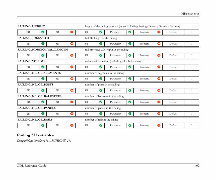
Miscellaneous
GDL Reference Guide 402
RAILING_HEIGHT height of the railing segment (as set in Railing Settings Dialog / Segment Settings)
2D 3D UI Parameter Property Default 0
RAILING_3DLENGTH full 3D length of the railing
2D 3D UI Parameter Property Default 0
RAILING_HORIZONTAL_LENGTH full projected 2D length of the railing
2D 3D UI Parameter Property Default 0
RAILING_VOLUME volume of the railing (including all subelements)
2D 3D UI Parameter Property Default 0
RAILING_NR_OF_SEGMENTS number of segments in the railing
2D 3D UI Parameter Property Default 0
RAILING_NR_OF_POSTS number of posts in the railing
2D 3D UI Parameter Property Default 0
RAILING_NR_OF_BALUSTERS number of balusters in the railing
2D 3D UI Parameter Property Default 0
RAILING_NR_OF_PANELS number of panels in the railing
2D 3D UI Parameter Property Default 0
RAILING_NR_OF_RAILS number of rails in the railing
2D 3D UI Parameter Property Default 0
Railing 3D variablesCompatibility: introduced in ARCHICAD 21.
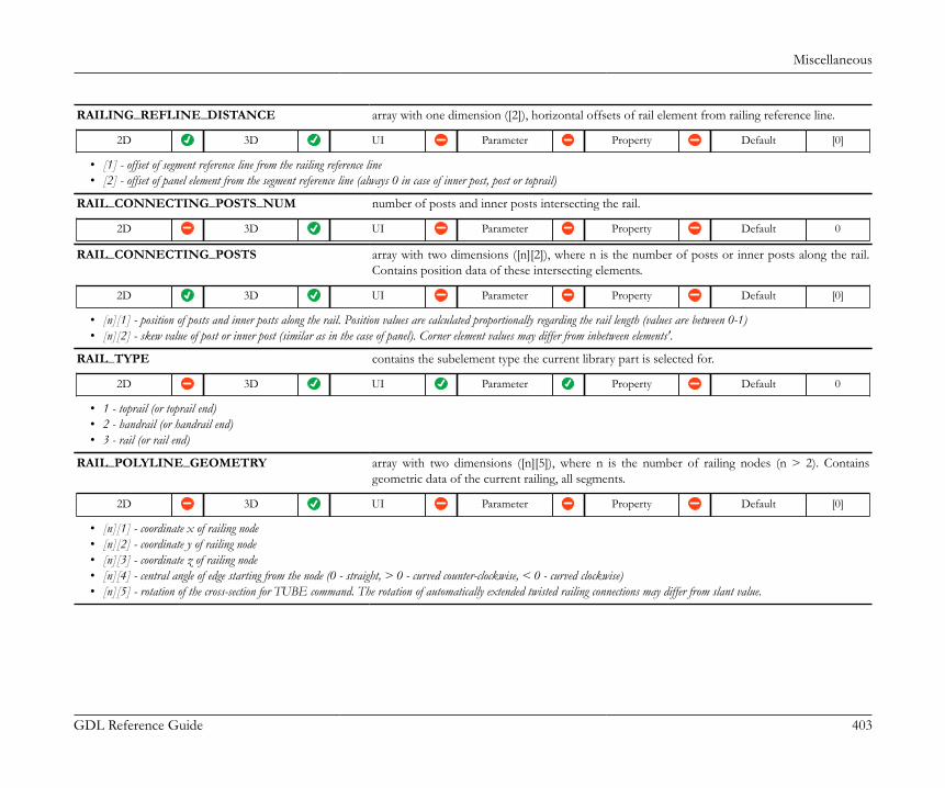
Miscellaneous
GDL Reference Guide 403
RAILING_REFLINE_DISTANCE array with one dimension ([2]), horizontal offsets of rail element from railing reference line.
2D 3D UI Parameter Property Default [0]
• [1] - offset of segment reference line from the railing reference line• [2] - offset of panel element from the segment reference line (always 0 in case of inner post, post or toprail)
RAIL_CONNECTING_POSTS_NUM number of posts and inner posts intersecting the rail.
2D 3D UI Parameter Property Default 0
RAIL_CONNECTING_POSTS array with two dimensions ([n][2]), where n is the number of posts or inner posts along the rail.Contains position data of these intersecting elements.
2D 3D UI Parameter Property Default [0]
• [n][1] - position of posts and inner posts along the rail. Position values are calculated proportionally regarding the rail length (values are between 0-1)• [n][2] - skew value of post or inner post (similar as in the case of panel). Corner element values may differ from inbetween elements'.
RAIL_TYPE contains the subelement type the current library part is selected for.
2D 3D UI Parameter Property Default 0
• 1 - toprail (or toprail end)• 2 - handrail (or handrail end)• 3 - rail (or rail end)
RAIL_POLYLINE_GEOMETRY array with two dimensions ([n][5]), where n is the number of railing nodes (n > 2). Containsgeometric data of the current railing, all segments.
2D 3D UI Parameter Property Default [0]
• [n][1] - coordinate x of railing node• [n][2] - coordinate y of railing node• [n][3] - coordinate z of railing node• [n][4] - central angle of edge starting from the node (0 - straight, > 0 - curved counter-clockwise, < 0 - curved clockwise)• [n][5] - rotation of the cross-section for TUBE command. The rotation of automatically extended twisted railing connections may differ from slant value.
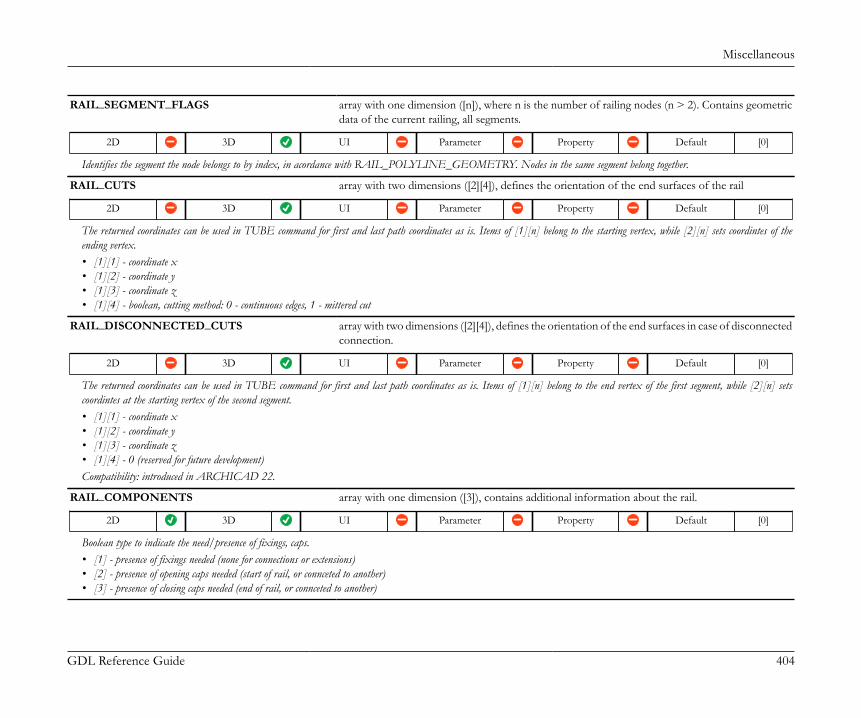
Miscellaneous
GDL Reference Guide 404
RAIL_SEGMENT_FLAGS array with one dimension ([n]), where n is the number of railing nodes (n > 2). Contains geometricdata of the current railing, all segments.
2D 3D UI Parameter Property Default [0]
Identifies the segment the node belongs to by index, in acordance with RAIL_POLYLINE_GEOMETRY. Nodes in the same segment belong together.
RAIL_CUTS array with two dimensions ([2][4]), defines the orientation of the end surfaces of the rail
2D 3D UI Parameter Property Default [0]
The returned coordinates can be used in TUBE command for first and last path coordinates as is. Items of [1][n] belong to the starting vertex, while [2][n] sets coordintes of theending vertex.• [1][1] - coordinate x• [1][2] - coordinate y• [1][3] - coordinate z• [1][4] - boolean, cutting method: 0 - continuous edges, 1 - mittered cut
RAIL_DISCONNECTED_CUTS array with two dimensions ([2][4]), defines the orientation of the end surfaces in case of disconnectedconnection.
2D 3D UI Parameter Property Default [0]
The returned coordinates can be used in TUBE command for first and last path coordinates as is. Items of [1][n] belong to the end vertex of the first segment, while [2][n] setscoordintes at the starting vertex of the second segment.• [1][1] - coordinate x• [1][2] - coordinate y• [1][3] - coordinate z• [1][4] - 0 (reserved for future development)Compatibility: introduced in ARCHICAD 22.
RAIL_COMPONENTS array with one dimension ([3]), contains additional information about the rail.
2D 3D UI Parameter Property Default [0]
Boolean type to indicate the need/presence of fixings, caps.• [1] - presence of fixings needed (none for connections or extensions)• [2] - presence of opening caps needed (start of rail, or connceted to another)• [3] - presence of closing caps needed (end of rail, or connceted to another)

Miscellaneous
GDL Reference Guide 405
RAIL_SLANT_ANGLE rail slant angle in degrees relative to vertical direction, perpendicular to walking direction.
2D 3D UI Parameter Property Default 0
values: possible values (< 90 degrees)positive: slanting to the left relative to walking directionnegative: slanting to the right relative to walking direction
Curved sections: the angle is measured on a vertical, radial plane.
RAILINGPANEL_TYPE generic geometry type of the panel.
2D 3D UI Parameter Property Default 0
• 1 - planar• 2 - cylindrical (curved - vertical or curved - skewed)• 3 - conic (curved - horizontal - slanted)• 4 - twisted (curved - inclined - slanted or curved - slanted - skewed)
RAILINGPANEL_UNCUT_GEOMETRY array with two dimensions ([n][4]), where n is the number of panel nodes (n > 3). Contains geometricdata of the current railing panel, complete raw geometry (without cuts).
2D 3D UI Parameter Property Default [0]
• [n][1] - coordinate x of railing panel node• [n][2] - coordinate y of railing panel node• [n][3] - coordinate z of railing panel node• [n][4] - central angle of edge starting from the node (0 - straight, > 0 - curved counter-clockwise, < 0 - curved clockwise)
RAILINGPANEL_GEOMETRY array with two dimensions ([n][5]), where n is the number of panel nodes (n > 3). Contains geometricdata of the current railing panel, cutting planes applied.
2D 3D UI Parameter Property Default [0]
• [n][1] - coordinate x of railing panel node• [n][2] - coordinate y of railing panel node• [n][3] - coordinate z of railing panel node• [n][4] - central angle of edge starting from the node (0 - straight, > 0 - curved counter-clockwise, < 0 - curved clockwise)• [n][5] - in case of a cut edge, contains the cutting plane angle (0 - perpendicular to panel). In case of a curved panel, the reference plane is tangential.
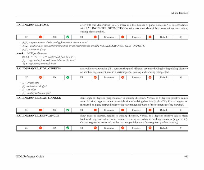
Miscellaneous
GDL Reference Guide 406
RAILINGPANEL_FLAGS array with two dimensions ([n][3]), where n is the number of panel nodes (n > 3) in accordancewith RAILINGPANEL_GEOMETRY. Contains geometric data of the current railing panel edges,cutting planes applied.
2D 3D UI Parameter Property Default [0]
• [n][1] - segment number of edge starting from node in the uncut panel• [n][2] - position of the edge starting from node in the cut panel (indexing according to RAILINGPANEL_SIDE_OFFSETS)• [n][3] - status bit of edge
mask: [n][3] possible valuesmask = j1 + 2*j2, where each j can be 0 or 1.j1: edge starting from node connected to another panelj2: edge starting from node is cut
RAILINGPANEL_SIDE_OFFSETS array with one dimension ([4]), contains the panel offsets as set in the Railing Settings dialog, distanceof neihbouring element axes in a vertical plane, slanting and skewing disregarded.
2D 3D UI Parameter Property Default [0]
• [1] - bottom offset• [2] - end vertex side offset• [3] - top offset• [4] - starting vertex side offset
RAILINGPANEL_SLANT_ANGLE slant angle in degrees, perpendicular to walking direction. Vertical is 0 degrees, positive valuesmean left side, negative values mean right side of walking direction (angle < 90). Curved segments:measured on plane perpendicular to the start tangential plane of the segment (before skewing).
2D 3D UI Parameter Property Default 0
RAILINGPANEL_SKEW_ANGLE skew angle in degrees, parallel to walking direction. Vertical is 0 degrees, positive values meanbackward, negative values mean forward skewing according to walking direction (angle < 90).Curved segments: measured on the start tangential plane of the segment (before slanting).
2D 3D UI Parameter Property Default 0

Miscellaneous
GDL Reference Guide 407
RAILINGPOST_TYPE contains the subelement type the current library part is selected for.
2D 3D UI Parameter Property Default 0
• 1 - post• 2 - inner post• 3 - baluster
RAILINGPOST_TOP_COORD array with one dimension ([3]), coordinates of the top of the current post
2D 3D UI Parameter Property Default [0, 0, 0]
• [1] - coordinate x• [2] - coordinate y• [3] - coordinate z
RAILINGPOST_CUTS array with two dimensions ([2][3]), defines the orientation of the end surfaces of the post
2D 3D UI Parameter Property Default [0]
The returned coordinates can be used in TUBE command for first and last path coordinates as is. Items of [1][n] belong to the base vertex, while [2][n] sets coordintes of the top vertex.• [1][1] - coordinate x• [1][2] - coordinate y• [1][3] - coordinate z
RAILINGPOST_SEGMENT_CUTS array with two dimensions ([2][4]), contains the vector parameters of two planes used to cut innerposts and balusters at the boundary of the segment, when the railing is slanted
2D 3D UI Parameter Property Default [0]
The normal of the plane is vector (A; B; C), and D is its distance from the origin, measured in the direction of the normal. The model should be cut in the direction of the normal.In case of all 0 return values for any of the 2 planes, the plane does not exist (no cut).• [1][1] - A• [1][2] - B• [1][3] - C• [1][4] - D
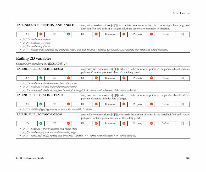
Miscellaneous
GDL Reference Guide 408
RAILINGEND_DIRECTION_AND_ANGLE array with two dimensions ([n][5]), vector data pointing away from the connecting rail in a tangentialdirection. For two ends of a straight rail, these vectors are opponent in direction.
2D 3D UI Parameter Property Default [0]
• [n][1] - coordinate x of vector• [n][2] - coordinate y of vector• [n][3] - coordinate z of vector• [n][4] - rotation of the connecting rail around the vector’s axis, with the effect of slanting. The railend should model the same rotation to connect seamlessly.
Railing 2D variablesCompatibility: introduced in ARCHICAD 21.
RAIL2D_FULL_POLYLINE_GEOM array with two dimensions ([n][3]), where n is the number of points in the panel/rail/rail end axispolyline. Contains geometric data of the railing panel.
2D 3D UI Parameter Property Default [0]
• [n][1] - coordinate x of node measured from railing origin• [n][2] - coordinate y of node measured from railing origin• [n][3] - central angle of edge starting from the node (0 - straight, > 0 - curved counter-clockwise, < 0 - curved clockwise)
RAIL2D_FULL_POLYLINE_FLAGS array with two dimensions ([n][1]), where n is the number of points in the panel/rail/rail end axispolyline. Contains visibility data of edges.
2D 3D UI Parameter Property Default [0]
• [n][1] - visibility flag of edge starting at node n (0 - not visible, 1 - visible)
RAIL2D_FULL_POLYGON_GEOM array with two dimensions ([n][3]), where n is the number of points in the panel/rail/rail end symbolpolygon. Contains geometric data of the railing panel.
2D 3D UI Parameter Property Default [0]
• [n][1] - coordinate x of node measured from railing origin• [n][2] - coordinate y of node measured from railing origin• [n][3] - central angle of edge starting from the node (0 - straight, > 0 - curved counter-clockwise, < 0 - curved clockwise)

Miscellaneous
GDL Reference Guide 409
RAIL2D_FULL_POLYGON_FLAGS array with two dimensions ([n][1]), where n is the number of points in the panel/rail/rail end symbolpolygon. Contains visibility data of edges.
2D 3D UI Parameter Property Default [0]
• [n][1] - visibility flag of edge starting at node n (0 - not visible, 1 - visible)
RAIL2D_FULL_VISIBILITY type of the active attribute set of the current railing drawing.
2D 3D UI Parameter Property Default 0
values:1: 'Visible' attribute set is in effect0: 'Hidden' attribute set is in effect
RAIL2D_CUSTOMDISPLAY contains information about the model view settings of the railing.
2D 3D UI Parameter Property Default 0
values:0: railing is displayed according to Model View Option settings1: railing is displayed with custom settings
The following globals are used to define the parts of the railing represented below the first breakmark.
RAIL2D_LOWER_POLYLINE_GEOM array with two dimensions ([n][3]), where n is the number of points in the panel/rail/rail end axispolyline below the first breakmark. Contains geometric data of the railing panel polyline.
2D 3D UI Parameter Property Default [0]
• [n][1] - coordinate x of node measured from railing origin• [n][2] - coordinate y of node measured from railing origin• [n][3] - central angle of edge starting from the node (0 - straight, > 0 - curved counter-clockwise, < 0 - curved clockwise)
RAIL2D_LOWER_POLYLINE_FLAGS array with two dimensions ([n][1]), where n is the number of points in the panel/rail/rail end axispolyline below the first breakmark. Contains visibility data of edges.
2D 3D UI Parameter Property Default [0]
• [n][1] - visibility flag of edge starting at node n (0 - not visible, 1 - visible)
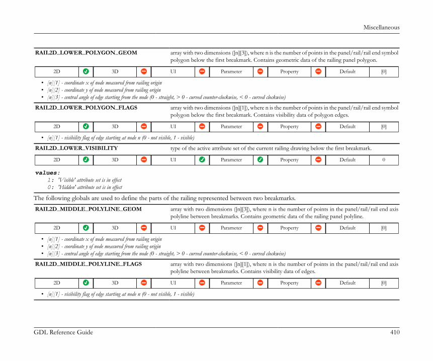
Miscellaneous
GDL Reference Guide 410
RAIL2D_LOWER_POLYGON_GEOM array with two dimensions ([n][3]), where n is the number of points in the panel/rail/rail end symbolpolygon below the first breakmark. Contains geometric data of the railing panel polygon.
2D 3D UI Parameter Property Default [0]
• [n][1] - coordinate x of node measured from railing origin• [n][2] - coordinate y of node measured from railing origin• [n][3] - central angle of edge starting from the node (0 - straight, > 0 - curved counter-clockwise, < 0 - curved clockwise)
RAIL2D_LOWER_POLYGON_FLAGS array with two dimensions ([n][1]), where n is the number of points in the panel/rail/rail end symbolpolygon below the first breakmark. Contains visibility data of polygon edges.
2D 3D UI Parameter Property Default [0]
• [n][1] - visibility flag of edge starting at node n (0 - not visible, 1 - visible)
RAIL2D_LOWER_VISIBILITY type of the active attribute set of the current railing drawing below the first breakmark.
2D 3D UI Parameter Property Default 0
values:1: 'Visible' attribute set is in effect0: 'Hidden' attribute set is in effect
The following globals are used to define the parts of the railing represented between two breakmarks.
RAIL2D_MIDDLE_POLYLINE_GEOM array with two dimensions ([n][3]), where n is the number of points in the panel/rail/rail end axispolyline between breakmarks. Contains geometric data of the railing panel polyline.
2D 3D UI Parameter Property Default [0]
• [n][1] - coordinate x of node measured from railing origin• [n][2] - coordinate y of node measured from railing origin• [n][3] - central angle of edge starting from the node (0 - straight, > 0 - curved counter-clockwise, < 0 - curved clockwise)
RAIL2D_MIDDLE_POLYLINE_FLAGS array with two dimensions ([n][1]), where n is the number of points in the panel/rail/rail end axispolyline between breakmarks. Contains visibility data of edges.
2D 3D UI Parameter Property Default [0]
• [n][1] - visibility flag of edge starting at node n (0 - not visible, 1 - visible)

Miscellaneous
GDL Reference Guide 411
RAIL2D_MIDDLE_POLYGON_GEOM array with two dimensions ([n][3]), where n is the number of points in the panel/rail/rail end symbolpolygon between breakmarks. Contains geometric data of the railing panel polygon.
2D 3D UI Parameter Property Default [0]
• [n][1] - coordinate x of node measured from railing origin• [n][2] - coordinate y of node measured from railing origin• [n][3] - central angle of edge starting from the node (0 - straight, > 0 - curved counter-clockwise, < 0 - curved clockwise)
RAIL2D_MIDDLE_POLYGON_FLAGS array with two dimensions ([n][1]), where n is the number of points in the panel/rail/rail end symbolpolygon between breakmarks. Contains visibility data of polygon edges.
2D 3D UI Parameter Property Default [0]
• [n][1] - visibility flag of edge starting at node n (0 - not visible, 1 - visible)
RAIL2D_MIDDLE_VISIBILITY type of the active attribute set of the current railing drawing between breakmarks.
2D 3D UI Parameter Property Default 0
values:1: 'Visible' attribute set is in effect0: 'Hidden' attribute set is in effect
The following globals are used to define the parts of the railing represented above the last breakmark.
RAIL2D_UPPER_POLYLINE_GEOM array with two dimensions ([n][3]), where n is the number of points in the panel/rail/rail end axispolyline above the last breakmark. Contains geometric data of the railing panel polyline.
2D 3D UI Parameter Property Default [0]
• [n][1] - coordinate x of node measured from railing origin• [n][2] - coordinate y of node measured from railing origin• [n][3] - central angle of edge starting from the node (0 - straight, > 0 - curved counter-clockwise, < 0 - curved clockwise)
RAIL2D_UPPER_POLYLINE_FLAGS array with two dimensions ([n][1]), where n is the number of points in the panel/rail/rail end axispolyline above the last breakmark. Contains visibility data of edges.
2D 3D UI Parameter Property Default [0]
• [n][1] - visibility flag of edge starting at node n (0 - not visible, 1 - visible)

Miscellaneous
GDL Reference Guide 412
RAIL2D_UPPER_POLYGON_GEOM array with two dimensions ([n][3]), where n is the number of points in the panel/rail/rail end symbolpolygon above the last breakmark. Contains geometric data of the railing panel polygon.
2D 3D UI Parameter Property Default [0]
• [n][1] - coordinate x of node measured from railing origin• [n][2] - coordinate y of node measured from railing origin• [n][3] - central angle of edge starting from the node (0 - straight, > 0 - curved counter-clockwise, < 0 - curved clockwise)
RAIL2D_UPPER_POLYGON_FLAGS array with two dimensions ([n][1]), where n is the number of points in the panel/rail/rail end symbolpolygon above the last breakmark. Contains visibility data of polygon edges.
2D 3D UI Parameter Property Default [0]
• [n][1] - visibility flag of edge starting at node n (0 - not visible, 1 - visible)
RAIL2D_UPPER_VISIBILITY type of the active attribute set of the current railing drawing above the last breakmark.
2D 3D UI Parameter Property Default 0
values:1: 'Visible' attribute set is in effect0: 'Hidden' attribute set is in effect
The following global belongs to the 2D representation of railing posts.RAILPOST2D_VISIBILITY type of the active attribute set of the current post drawing.
2D 3D UI Parameter Property Default 0
values:1: 'Visible' attribute set is in effect0: 'Hidden' attribute set is in effect
Roof parameters - available for skylights, listing and labelsROOF_THICKNESS thickness of the roof
ROOF_ANGLE slope of the roof
ROOF_MAT_TOP surface attribute index of the top surface of the roof
ROOF_MAT_EDGE surface attribute index of the edges of the roof
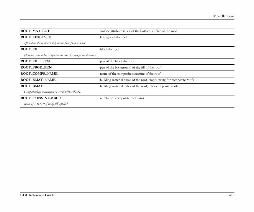
Miscellaneous
GDL Reference Guide 413
ROOF_MAT_BOTT surface attribute index of the bottom surface of the roof
ROOF_LINETYPE line type of the roof
applied on the contours only in the floor plan window
ROOF_FILL fill of the roof
fill index - its value is negative in case of a composite structure
ROOF_FILL_PEN pen of the fill of the roof
ROOF_FBGD_PEN pen of the background of the fill of the roof
ROOF_COMPS_NAME name of the composite structure of the roof
ROOF_BMAT_NAME building material name of the roof, empty string for composite roofs
ROOF_BMAT building material index of the roof, 0 for composite roofs
Compatibility: introduced in ARCHICAD 21.
ROOF_SKINS_NUMBER number of composite roof skins
range of 1 to 8, 0 if single fill applied

Miscellaneous
GDL Reference Guide 414
ROOF_SKINS_PARAMS parameters of the composite roof skin
array with 18 columns with arbitrary number of rows:• [1] fill• [2] thickness• [3] (old contour pen)• [4] pen of fill• [5] pen of fill background• [6] core status• [7] upper line pen• [8] upper line type• [9] lower line pen• [10] lower line type• [11] end face pen• [12] fill orientation• [13] skin type• [14] end face line type• [15] finish skin status• [16] oriented fill status• [17] core skin status (if no core skin exists, the thickest skin)• [18] building material index.core status: 0 - not part, 1 - part, 3 - last skin of core, fill orientation: 0 - global, 1 - local; skin type: in the current ARCHICAD always 0 - cut, it can be used as in wallslater; finish skin status: 0 not finish skin, 1: finish skin
ROOF_SKINS_BMAT_NAMES building material names of the composite roof skin
array with 1 column: building material name of the skin and with arbitrary number of rows.
ROOF_SECT_PEN pen of the contours of the roof cut surfaces
applied on contours of cut surfaces both in floor plan and section/elevation windows
ROOF_VIEW_PEN pen of the roof on view
applied on all edges in 3D window and on outline edges (edges on view below cutting plane) in floor plan and section/elevation windows
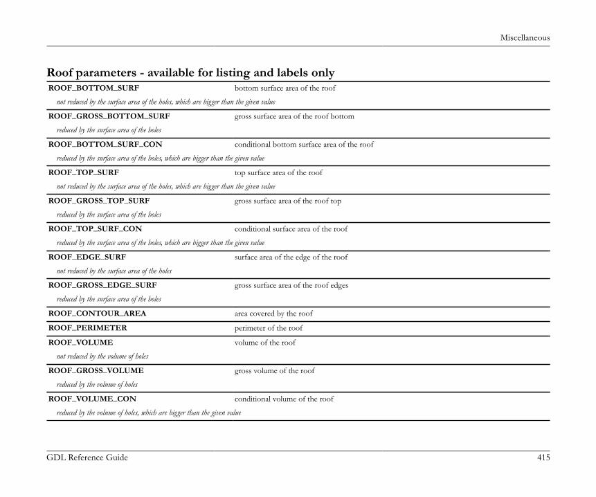
Miscellaneous
GDL Reference Guide 415
Roof parameters - available for listing and labels onlyROOF_BOTTOM_SURF bottom surface area of the roof
not reduced by the surface area of the holes, which are bigger than the given value
ROOF_GROSS_BOTTOM_SURF gross surface area of the roof bottom
reduced by the surface area of the holes
ROOF_BOTTOM_SURF_CON conditional bottom surface area of the roof
reduced by the surface area of the holes, which are bigger than the given value
ROOF_TOP_SURF top surface area of the roof
not reduced by the surface area of the holes, which are bigger than the given value
ROOF_GROSS_TOP_SURF gross surface area of the roof top
reduced by the surface area of the holes
ROOF_TOP_SURF_CON conditional surface area of the roof
reduced by the surface area of the holes, which are bigger than the given value
ROOF_EDGE_SURF surface area of the edge of the roof
not reduced by the surface area of the holes
ROOF_GROSS_EDGE_SURF gross surface area of the roof edges
reduced by the surface area of the holes
ROOF_CONTOUR_AREA area covered by the roof
ROOF_PERIMETER perimeter of the roof
ROOF_VOLUME volume of the roof
not reduced by the volume of holes
ROOF_GROSS_VOLUME gross volume of the roof
reduced by the volume of holes
ROOF_VOLUME_CON conditional volume of the roof
reduced by the volume of holes, which are bigger than the given value
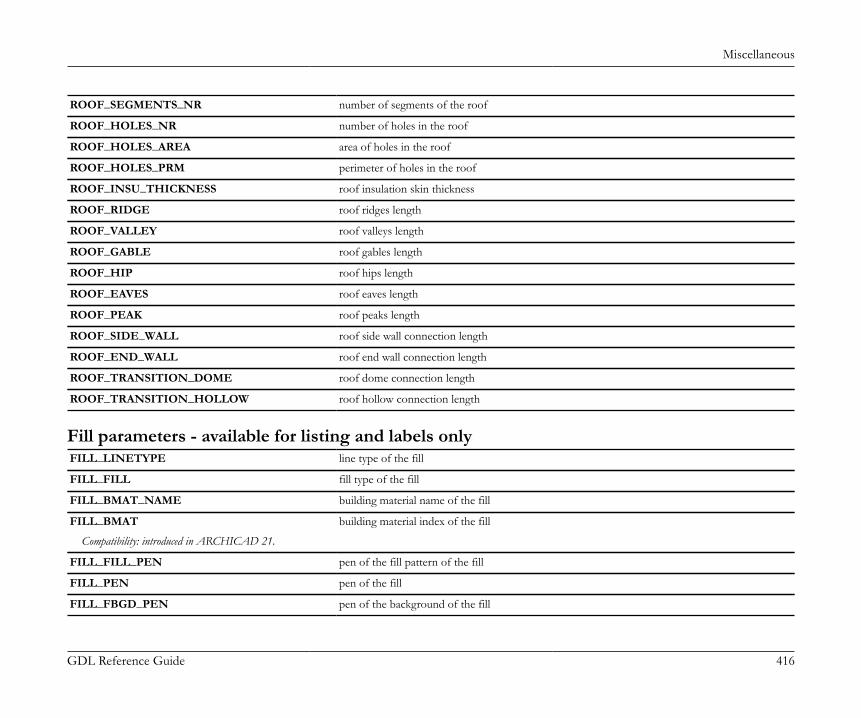
Miscellaneous
GDL Reference Guide 416
ROOF_SEGMENTS_NR number of segments of the roof
ROOF_HOLES_NR number of holes in the roof
ROOF_HOLES_AREA area of holes in the roof
ROOF_HOLES_PRM perimeter of holes in the roof
ROOF_INSU_THICKNESS roof insulation skin thickness
ROOF_RIDGE roof ridges length
ROOF_VALLEY roof valleys length
ROOF_GABLE roof gables length
ROOF_HIP roof hips length
ROOF_EAVES roof eaves length
ROOF_PEAK roof peaks length
ROOF_SIDE_WALL roof side wall connection length
ROOF_END_WALL roof end wall connection length
ROOF_TRANSITION_DOME roof dome connection length
ROOF_TRANSITION_HOLLOW roof hollow connection length
Fill parameters - available for listing and labels onlyFILL_LINETYPE line type of the fill
FILL_FILL fill type of the fill
FILL_BMAT_NAME building material name of the fill
FILL_BMAT building material index of the fill
Compatibility: introduced in ARCHICAD 21.
FILL_FILL_PEN pen of the fill pattern of the fill
FILL_PEN pen of the fill
FILL_FBGD_PEN pen of the background of the fill
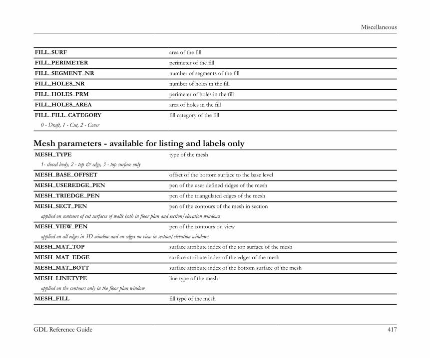
Miscellaneous
GDL Reference Guide 417
FILL_SURF area of the fill
FILL_PERIMETER perimeter of the fill
FILL_SEGMENT_NR number of segments of the fill
FILL_HOLES_NR number of holes in the fill
FILL_HOLES_PRM perimeter of holes in the fill
FILL_HOLES_AREA area of holes in the fill
FILL_FILL_CATEGORY fill category of the fill
0 - Draft, 1 - Cut, 2 - Cover
Mesh parameters - available for listing and labels onlyMESH_TYPE type of the mesh
1- closed body, 2 - top & edge, 3 - top surface only
MESH_BASE_OFFSET offset of the bottom surface to the base level
MESH_USEREDGE_PEN pen of the user defined ridges of the mesh
MESH_TRIEDGE_PEN pen of the triangulated edges of the mesh
MESH_SECT_PEN pen of the contours of the mesh in section
applied on contours of cut surfaces of walls both in floor plan and section/elevation windows
MESH_VIEW_PEN pen of the contours on view
applied on all edges in 3D window and on edges on view in section/elevation windows
MESH_MAT_TOP surface attribute index of the top surface of the mesh
MESH_MAT_EDGE surface attribute index of the edges of the mesh
MESH_MAT_BOTT surface attribute index of the bottom surface of the mesh
MESH_LINETYPE line type of the mesh
applied on the contours only in the floor plan window
MESH_FILL fill type of the mesh

Miscellaneous
GDL Reference Guide 418
MESH_BMAT_NAME building material name of the mesh
MESH_BMAT building material index of the mesh
Compatibility: introduced in ARCHICAD 21.
MESH_FILL_PEN pen of the fill of the mesh
MESH_FBGD_PEN pen of the background of the fill of the mesh
MESH_BOTTOM_SURF bottom surface area of the mesh
MESH_TOP_SURF top surface area of the mesh
MESH_EDGE_SURF surface area of the edge of the mesh
MESH_PERIMETER perimeter of the mesh
MESH_VOLUME volume of the mesh
MESH_SEGMENTS_NR number of segments of the mesh
MESH_HOLES_NR number of holes in the mesh
MESH_HOLES_AREA area of holes in the mesh
MESH_HOLES_PRM perimeter of holes in the mesh
Curtain Wall component parametersCW_BOUNDARY_PLACEMENT Placement of the curtain wall frame
2D 3D UI Parameter Property Default 0
Compatibility: introduced in ARCHICAD 22.Contains the Placement settings of the boundary frames defined at Curtain Wall System / Member Placement.
values:0: Center on Boundary, or the actual frame is not a boundary frame.-1: Inside Boundary1: Outside Boundary
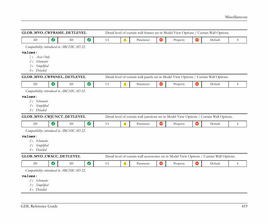
Miscellaneous
GDL Reference Guide 419
GLOB_MVO_CWFRAME_DETLEVEL Detail level of curtain wall frames set in Model View Options / Curtain Wall Options.
2D 3D UI Parameter Property Default 4
Compatibility: introduced in ARCHICAD 22.values:
1: Axis Only2: Schematic3: Simplified4: Detailed
GLOB_MVO_CWPANEL_DETLEVEL Detail level of curtain wall panels set in Model View Options / Curtain Wall Options.
2D 3D UI Parameter Property Default 4
Compatibility: introduced in ARCHICAD 22.values:
2: Schematic3: Simplified4: Detailed
GLOB_MVO_CWJUNCT_DETLEVEL Detail level of curtain wall junctions set in Model View Options / Curtain Wall Options.
2D 3D UI Parameter Property Default 4
Compatibility: introduced in ARCHICAD 22.values:
2: Schematic3: Simplified4: Detailed
GLOB_MVO_CWACC_DETLEVEL Detail level of curtain wall accessories set in Model View Options / Curtain Wall Options.
2D 3D UI Parameter Property Default 4
Compatibility: introduced in ARCHICAD 22.values:
2: Schematic3: Simplified4: Detailed
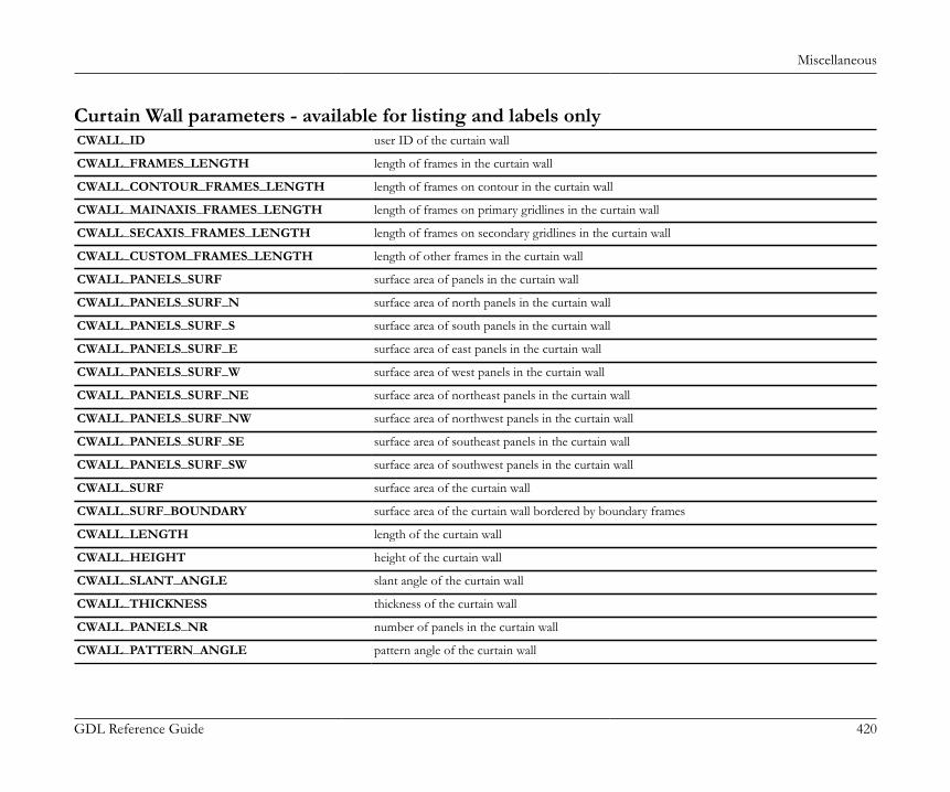
Miscellaneous
GDL Reference Guide 420
Curtain Wall parameters - available for listing and labels onlyCWALL_ID user ID of the curtain wall
CWALL_FRAMES_LENGTH length of frames in the curtain wall
CWALL_CONTOUR_FRAMES_LENGTH length of frames on contour in the curtain wall
CWALL_MAINAXIS_FRAMES_LENGTH length of frames on primary gridlines in the curtain wall
CWALL_SECAXIS_FRAMES_LENGTH length of frames on secondary gridlines in the curtain wall
CWALL_CUSTOM_FRAMES_LENGTH length of other frames in the curtain wall
CWALL_PANELS_SURF surface area of panels in the curtain wall
CWALL_PANELS_SURF_N surface area of north panels in the curtain wall
CWALL_PANELS_SURF_S surface area of south panels in the curtain wall
CWALL_PANELS_SURF_E surface area of east panels in the curtain wall
CWALL_PANELS_SURF_W surface area of west panels in the curtain wall
CWALL_PANELS_SURF_NE surface area of northeast panels in the curtain wall
CWALL_PANELS_SURF_NW surface area of northwest panels in the curtain wall
CWALL_PANELS_SURF_SE surface area of southeast panels in the curtain wall
CWALL_PANELS_SURF_SW surface area of southwest panels in the curtain wall
CWALL_SURF surface area of the curtain wall
CWALL_SURF_BOUNDARY surface area of the curtain wall bordered by boundary frames
CWALL_LENGTH length of the curtain wall
CWALL_HEIGHT height of the curtain wall
CWALL_SLANT_ANGLE slant angle of the curtain wall
CWALL_THICKNESS thickness of the curtain wall
CWALL_PANELS_NR number of panels in the curtain wall
CWALL_PATTERN_ANGLE pattern angle of the curtain wall
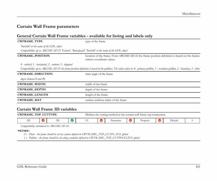
Miscellaneous
GDL Reference Guide 421
Curtain Wall Frame parameters
General Curtain Wall Frame variables - available for listing and labels onlyCWFRAME_TYPE type of the frame
'Invisible' or the name of the GDL objectCompatibility: up to ARCHICAD 21 'Generic', 'Butt-glazed', 'Invisible' or the name of the GDL object
CWFRAME_POSITION location of the frame. From ARCHICAD 22 the frame position definition is based on the framesrelative coordinate values.
0 - vertical, 1 - horizontal, 2 - contour, 3 - diagonalCompatibility: up to ARCHICAD 21 the frame position definition is based on the gridlines. The values refers to: 0 - primary gridline, 1 - secondary gridline, 2 - boundary, 3 - other
CWFRAME_DIRECTION slant angle of the frame
degree between 0 and 90
CWFRAME_WIDTH width of the frame
CWFRAME_DEPTH depth of the frame
CWFRAME_LENGTH length of the frame
CWFRAME_MAT surface attribute index of the frame
Curtain Wall Frame 3D variablesCWFRAME_TOP_CUTTYPE Defines the cutting method at the curtain wall frame top connection.
2D 3D UI Parameter Property Default 0
Compatibility: introduced in ARCHICAD 22.values:
0: Plane - the frame should be cut by a plane defined in CWFRAME_TOP_CUTPLANE global1: Polyline - the frame should be cut along a polyline defined in CWFRAME_TOP_CUTPOLYLINE global
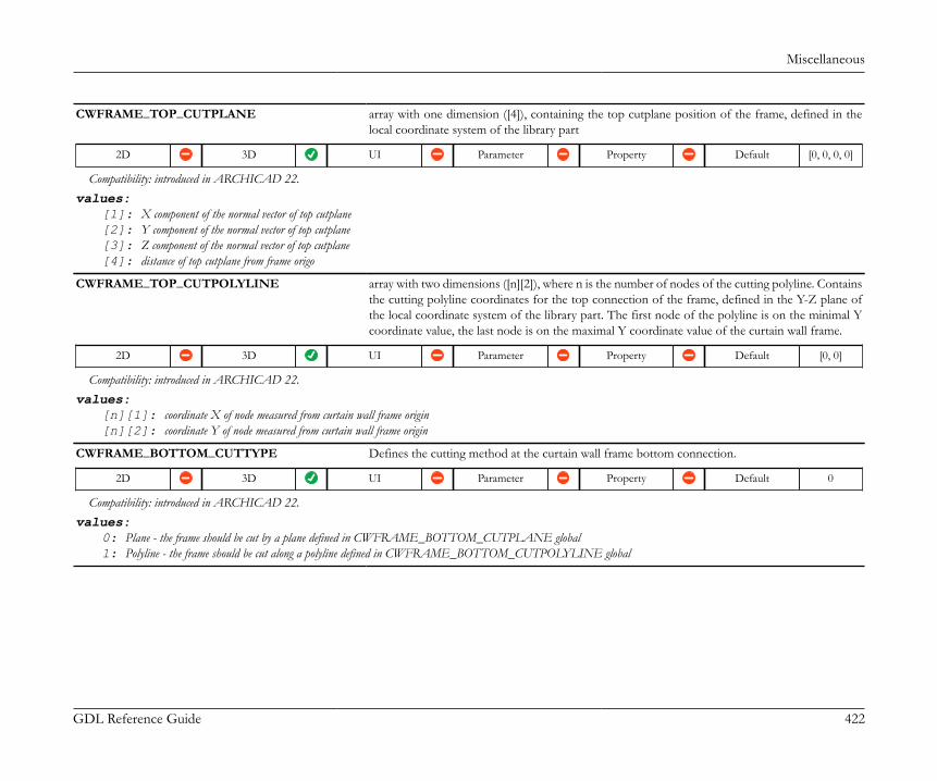
Miscellaneous
GDL Reference Guide 422
CWFRAME_TOP_CUTPLANE array with one dimension ([4]), containing the top cutplane position of the frame, defined in thelocal coordinate system of the library part
2D 3D UI Parameter Property Default [0, 0, 0, 0]
Compatibility: introduced in ARCHICAD 22.values:
[1]: X component of the normal vector of top cutplane[2]: Y component of the normal vector of top cutplane[3]: Z component of the normal vector of top cutplane[4]: distance of top cutplane from frame origo
CWFRAME_TOP_CUTPOLYLINE array with two dimensions ([n][2]), where n is the number of nodes of the cutting polyline. Containsthe cutting polyline coordinates for the top connection of the frame, defined in the Y-Z plane ofthe local coordinate system of the library part. The first node of the polyline is on the minimal Ycoordinate value, the last node is on the maximal Y coordinate value of the curtain wall frame.
2D 3D UI Parameter Property Default [0, 0]
Compatibility: introduced in ARCHICAD 22.values:
[n][1]: coordinate X of node measured from curtain wall frame origin[n][2]: coordinate Y of node measured from curtain wall frame origin
CWFRAME_BOTTOM_CUTTYPE Defines the cutting method at the curtain wall frame bottom connection.
2D 3D UI Parameter Property Default 0
Compatibility: introduced in ARCHICAD 22.values:
0: Plane - the frame should be cut by a plane defined in CWFRAME_BOTTOM_CUTPLANE global1: Polyline - the frame should be cut along a polyline defined in CWFRAME_BOTTOM_CUTPOLYLINE global
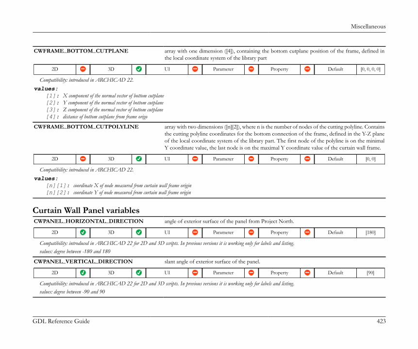
Miscellaneous
GDL Reference Guide 423
CWFRAME_BOTTOM_CUTPLANE array with one dimension ([4]), containing the bottom cutplane position of the frame, defined inthe local coordinate system of the library part
2D 3D UI Parameter Property Default [0, 0, 0, 0]
Compatibility: introduced in ARCHICAD 22.values:
[1]: X component of the normal vector of bottom cutplane[2]: Y component of the normal vector of bottom cutplane[3]: Z component of the normal vector of bottom cutplane[4]: distance of bottom cutplane from frame origo
CWFRAME_BOTTOM_CUTPOLYLINE array with two dimensions ([n][2]), where n is the number of nodes of the cutting polyline. Containsthe cutting polyline coordinates for the bottom connection of the frame, defined in the Y-Z planeof the local coordinate system of the library part. The first node of the polyline is on the minimalY coordinate value, the last node is on the maximal Y coordinate value of the curtain wall frame.
2D 3D UI Parameter Property Default [0, 0]
Compatibility: introduced in ARCHICAD 22.values:
[n][1]: coordinate X of node measured from curtain wall frame origin[n][2]: coordinate Y of node measured from curtain wall frame origin
Curtain Wall Panel variablesCWPANEL_HORIZONTAL_DIRECTION angle of exterior surface of the panel from Project North.
2D 3D UI Parameter Property Default [180]
Compatibility: introduced in ARCHICAD 22 for 2D and 3D scripts. In previous versions it is working only for labels and listing.values: degree between -180 and 180
CWPANEL_VERTICAL_DIRECTION slant angle of exterior surface of the panel.
2D 3D UI Parameter Property Default [90]
Compatibility: introduced in ARCHICAD 22 for 2D and 3D scripts. In previous versions it is working only for labels and listing.values: degree between -90 and 90
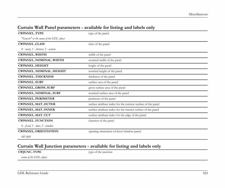
Miscellaneous
GDL Reference Guide 424
Curtain Wall Panel parameters - available for listing and labels onlyCWPANEL_TYPE type of the panel
"Generic" or the name of the GDL object
CWPANEL_CLASS class of the panel
0 - main, 1 - distinct, 2 - custom
CWPANEL_WIDTH width of the panel
CWPANEL_NOMINAL_WIDTH nominal width of the panel
CWPANEL_HEIGHT height of the panel
CWPANEL_NOMINAL_HEIGHT nominal height of the panel
CWPANEL_THICKNESS thickness of the panel
CWPANEL_SURF surface area of the panel
CWPANEL_GROSS_SURF gross surface area of the panel
CWPANEL_NOMINAL_SURF nominal surface area of the panel
CWPANEL_PERIMETER perimeter of the panel
CWPANEL_MAT_OUTER surface attribute index for the exterior surface of the panel
CWPANEL_MAT_INNER surface attribute index for the interior surface of the panel
CWPANEL_MAT_CUT surface attribute index for the edge of the panel
CWPANEL_FUNCTION function of the panel
0 - fixed, 1 - door, 2 - window
CWPANEL_ORIENTATION opening orientation of door/window panel
left/right
Curtain Wall Junction parameters - available for listing and labels onlyCWJUNC_TYPE type of the junction
name of the GDL object
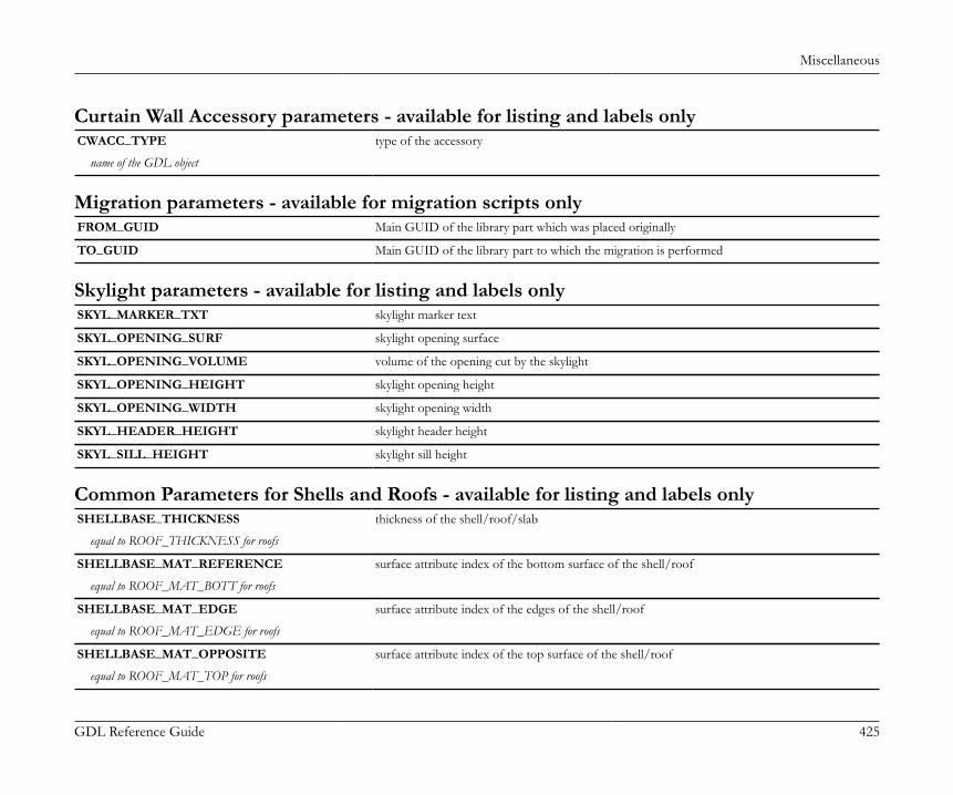
Miscellaneous
GDL Reference Guide 425
Curtain Wall Accessory parameters - available for listing and labels onlyCWACC_TYPE type of the accessory
name of the GDL object
Migration parameters - available for migration scripts onlyFROM_GUID Main GUID of the library part which was placed originally
TO_GUID Main GUID of the library part to which the migration is performed
Skylight parameters - available for listing and labels onlySKYL_MARKER_TXT skylight marker text
SKYL_OPENING_SURF skylight opening surface
SKYL_OPENING_VOLUME volume of the opening cut by the skylight
SKYL_OPENING_HEIGHT skylight opening height
SKYL_OPENING_WIDTH skylight opening width
SKYL_HEADER_HEIGHT skylight header height
SKYL_SILL_HEIGHT skylight sill height
Common Parameters for Shells and Roofs - available for listing and labels onlySHELLBASE_THICKNESS thickness of the shell/roof/slab
equal to ROOF_THICKNESS for roofs
SHELLBASE_MAT_REFERENCE surface attribute index of the bottom surface of the shell/roof
equal to ROOF_MAT_BOTT for roofs
SHELLBASE_MAT_EDGE surface attribute index of the edges of the shell/roof
equal to ROOF_MAT_EDGE for roofs
SHELLBASE_MAT_OPPOSITE surface attribute index of the top surface of the shell/roof
equal to ROOF_MAT_TOP for roofs
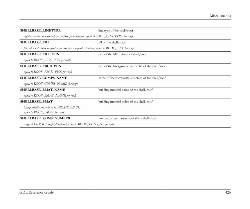
Miscellaneous
GDL Reference Guide 426
SHELLBASE_LINETYPE line type of the shell/roof
applied on the contours only in the floor plan window, equal to ROOF_LINETYPE for roofs
SHELLBASE_FILL fill of the shell/roof
fill index - its value is negative in case of a composite structure, equal to ROOF_FILL for roofs
SHELLBASE_FILL_PEN pen of the fill of the roof shell/roof
equal to ROOF_FILL_PEN for roofs
SHELLBASE_FBGD_PEN pen of the background of the fill of the shell/roof
equal to ROOF_FBGD_PEN for roofs
SHELLBASE_COMPS_NAME name of the composite structure of the shell/roof
equal to ROOF_COMPS_NAME for roofs
SHELLBASE_BMAT_NAME building material name of the shell/roof
equal to ROOF_BMAT_NAME for roofs
SHELLBASE_BMAT building material index of the shell/roof
Compatibility: introduced in ARCHICAD 21.equal to ROOF_BMAT for roofs
SHELLBASE_SKINS_NUMBER number of composite roof skins shell/roof
range of 1 to 8, 0 if single fill applied, equal to ROOF_SKINS_NR for roofs
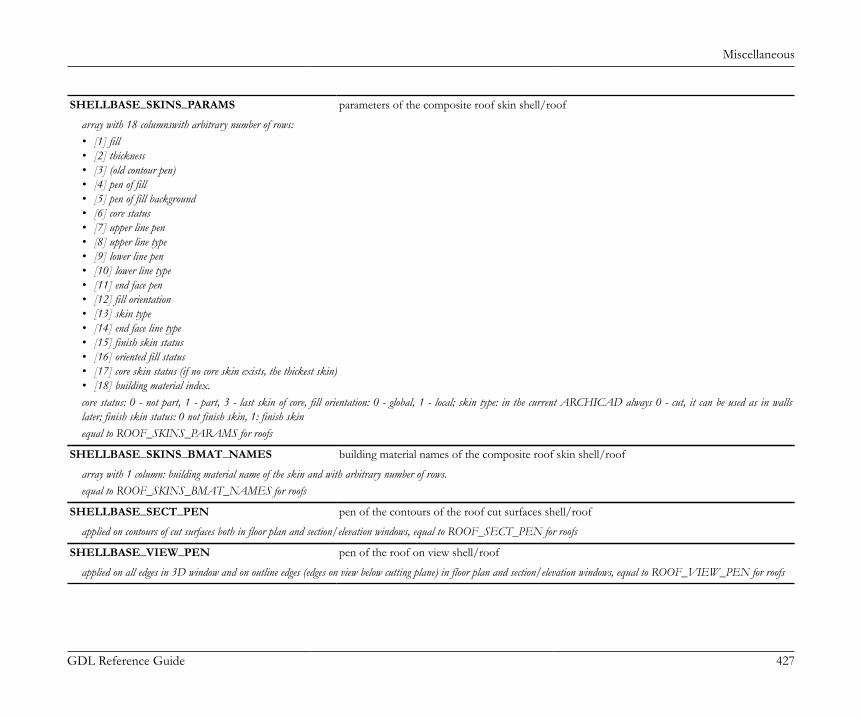
Miscellaneous
GDL Reference Guide 427
SHELLBASE_SKINS_PARAMS parameters of the composite roof skin shell/roof
array with 18 columnswith arbitrary number of rows:• [1] fill• [2] thickness• [3] (old contour pen)• [4] pen of fill• [5] pen of fill background• [6] core status• [7] upper line pen• [8] upper line type• [9] lower line pen• [10] lower line type• [11] end face pen• [12] fill orientation• [13] skin type• [14] end face line type• [15] finish skin status• [16] oriented fill status• [17] core skin status (if no core skin exists, the thickest skin)• [18] building material index.core status: 0 - not part, 1 - part, 3 - last skin of core, fill orientation: 0 - global, 1 - local; skin type: in the current ARCHICAD always 0 - cut, it can be used as in wallslater; finish skin status: 0 not finish skin, 1: finish skinequal to ROOF_SKINS_PARAMS for roofs
SHELLBASE_SKINS_BMAT_NAMES building material names of the composite roof skin shell/roof
array with 1 column: building material name of the skin and with arbitrary number of rows.equal to ROOF_SKINS_BMAT_NAMES for roofs
SHELLBASE_SECT_PEN pen of the contours of the roof cut surfaces shell/roof
applied on contours of cut surfaces both in floor plan and section/elevation windows, equal to ROOF_SECT_PEN for roofs
SHELLBASE_VIEW_PEN pen of the roof on view shell/roof
applied on all edges in 3D window and on outline edges (edges on view below cutting plane) in floor plan and section/elevation windows, equal to ROOF_VIEW_PEN for roofs

Miscellaneous
GDL Reference Guide 428
SHELLBASE_REFERENCE_SURF reference side surface of the shell/roof
not reduced by the surface of holes, equal to ROOF_BOTTOM_SURF for roofs
SHELLBASE_COND_REFERENCE_SURF conditional reference side surface of the shell/roof
equal to ROOF_BOTTOM_SURF_CON for roofs
SHELLBASE_GROSS_REFERENCE_SURF gross surface of the shell/roof reference side
reduced by the surface of the holes, equal to ROOF_GROSS_BOTTOM_SURF for roofs
SHELLBASE_OPPOSITE_SURF surface of the opposite side to the reference side of the shell/roof
not reduced by the surface of holes, equal to ROOF_TOP_SURF for roofs
SHELLBASE_COND_OPPOSITE_SURF conditional surface of the opposite side to the reference side of the shell/roof
reduced by the surface of the holes, which are bigger than the given value; equal to ROOF_TOP_SURF_CON for roofs
SHELLBASE_GROSS_OPPOSITE_SURF gross surface of the opposite side to the reference side of the shell/roof
reduced by the surface of the holes, equal to ROOF_GROSS_TOP_SURF for roofs
SHELLBASE_EDGE_SURF surface of the edge of the shell/roof
not reduced by the surface of holes, equal to ROOF_EDGE_SURF for roofs
SHELLBASE_GROSS_EDGE_SURF gross surface of the shell/roof edges
reduced by the surface of holes, equal to ROOF_GROSS_EDGE_SURF for roofs
SHELLBASE_PERIMETER perimeter of the shell/roof
equal to ROOF_PERIMETER for roofs
SHELLBASE_VOLUME volume of the shell/roof
not reduced by the volume of holes, equal to ROOF_VOLUME for roofs
SHELLBASE_COND_VOLUME conditional volume of the roof shell/roof
reduced by the volume of holes, which are bigger than the given value; equal to ROOF_VOLUME_CON for roofs
SHELLBASE_GROSS_VOLUME gross volume of the roof shell/roof
reduced by the volume of holes, equal to ROOF_GROSS_VOLUME for roofs

Miscellaneous
GDL Reference Guide 429
SHELLBASE_HOLES_NR number of holes in the shell/roof
equal to ROOF_HOLES_NR for roofs
SHELLBASE_HOLES_SURF surface of holes in the shell/roof
equal to ROOF_HOLES_AREA for roofs
SHELLBASE_HOLES_PRM perimeter of holes in the shell
equal to ROOF_HOLES_PRM for roofs
SHELLBASE_OPENINGS_NR number of openings in the shell
SHELLBASE_OPENINGS_SURF surface of openings in the shell
SHELLBASE_INSU_THICKNESS shell/roof insulation skin thickness
equal to ROOF_INSU_THICKNESS for roofs
SHELLBASE_RIDGE shell/roof ridges length
equal to ROOF_RIDGE for roofs
SHELLBASE_VALLEY shell/roof valleys length
equal to ROOF_VALLEY for roofs
SHELLBASE_GABLE shell/roof gables length
equal to ROOF_GABLE for roofs
SHELLBASE_HIP shell/roof hips length
equal to ROOF_HIP for roofs
SHELLBASE_EAVES shell/roof eaves length
equal to ROOF_EAVES for roofs
SHELLBASE_PEAK shell/roof peaks length
equal to ROOF_PEAK for roofs
SHELLBASE_SIDE_WALL shell/roof side wall connection length
equal to ROOF_SIDE_WALL for roofs

Miscellaneous
GDL Reference Guide 430
SHELLBASE_END_WALL shell/roof end wall connection length
equal to ROOF_END_WALL for roofs
SHELLBASE_TRANSITION_DOME shell/roof dome connection length
equal to ROOF_TRANSITION_DOME for roofs
SHELLBASE_TRANSITION_HOLLOW shell/roof hollow connection length
equal to ROOF_TRANSITION_HOLLOW for roofs
Parameters for Morphs - available for listing and labels onlyMORPH_LINETYPE Line type of the morph on view
MORPH_FILL Fill of the morph cut surfaces
MORPH_BMAT_NAME Building material name of the morph cut surfaces
MORPH_BMAT Building material index of the morph cut surfaces
Compatibility: introduced in ARCHICAD 21.
MORPH_FILL_PEN Pen of the morph cut surfaces
MORPH_FBGD_PEN Pen of the background of the fill of the morph cut surfaces
MORPH_SECT_LINETYPE Line type of the contours of the morph cut surfaces
MORPH_SECT_PEN Pen of the contours of the moprh cut surfaces
MORPH_VIEW_PEN Pen of the contours of the morph on view
MORPH_SOLID Morph body solid (on/off)
MORPH_MAT_DEFAULT Morph default surface attribute index
MORPH_CASTS_SHADOW Cast shadow (on/off)
MORPH_RECEIVES_SHADOW Receive shadow (on/off)
MORPH_SURFACE Gross surface of the morph
MORPH_VOLUME Volume of the morph
MORPH_FLOOR_PERIMETER perimeter of the morph on the floor plan
Miscellaneous
GDL Reference Guide 431
Free users’ globalsGLOB_USER_1
GLOB_USER_2
GLOB_USER_3
GLOB_USER_4
GLOB_USER_5
GLOB_USER_6
GLOB_USER_7
GLOB_USER_8
GLOB_USER_9
GLOB_USER_10 free variables 1 to 10 are initialized to number by default
GLOB_USER_11
GLOB_USER_12
GLOB_USER_13
GLOB_USER_14
GLOB_USER_15
GLOB_USER_16
GLOB_USER_17
GLOB_USER_18
GLOB_USER_19
GLOB_USER_20 free variables 11 to 20 are initialized to string by default

Miscellaneous
GDL Reference Guide 432
Example usage of global variables
Example: Illustrating the usage of the GLOB_WORLD_ORIGO_... globalsADD2 -GLOB_WORLD_ORIGO_OFFSET_X-SYMB_POS_X, -GLOB_WORLD_ORIGO_OFFSET_X-SYMB_POS_YLINE2 -0.1, 0.0, 0.1, 0.0LINE2 0.0, -0.1, 0.0, 0.1HOTSPOT2 0.0, 0.0, 1TEXT2 0, 0, "( 0.00 ; 0.00 )"TEXT2 0, 0.5, "World Origin"DEL TOPif ABS(GLOB_WORLD_ORIGO_OFFSET_X) > 0.01 OR\ ABS(GLOB_WORLD_ORIGO_OFFSET_Y) > 0.01 THEN ADD2 - SYMB_POS_X, - SYMB_POS_Y LINE2 -0.1, 0.0, 0.1, 0.0 LINE2 0.0, -0.1, 0.0, 0.1 HOTSPOT2 0.0, 0.0, 2 TEXT2 0, 0, "(" + STR (GLOB_WORLD_ORIGO_OFFSET_X, 9, 4) + "; " + STR (GLOB_WORLD_ORIGO_OFFSET_Y, 9, 4) + " )" TEXT2 0, 0.5, "Virtual Origin" DEL TOPENDIFif ABS(GLOB_WORLD_ORIGO_OFFSET_X + SYMB_POS_X) > 0.01 OR\ ABS(GLOB_WORLD_ORIGO_OFFSET_Y + SYMB_POS_Y) > 0.01 THEN LINE2 -0.1, 0.0, 0.1, 0.0 LINE2 0.0, -0.1, 0.0, 0.1 HOTSPOT2 0.0, 0.0, 3 TEXT2 0, 0, "(" + STR (GLOB_WORLD_ORIGO_OFFSET_X + SYMB_POS_X, 9, 4) + "; " + STR (GLOB_WORLD_ORIGO_OFFSET_Y + SYMB_POS_Y, 9, 4) + " )" TEXT2 0, 0.5, "Object Placement"ENDIF
Deprecated Global VariablesThese globals are still working in ARCHICAD's environment for compatibility reasons, but avoiding them is recommended during new objectcreation.
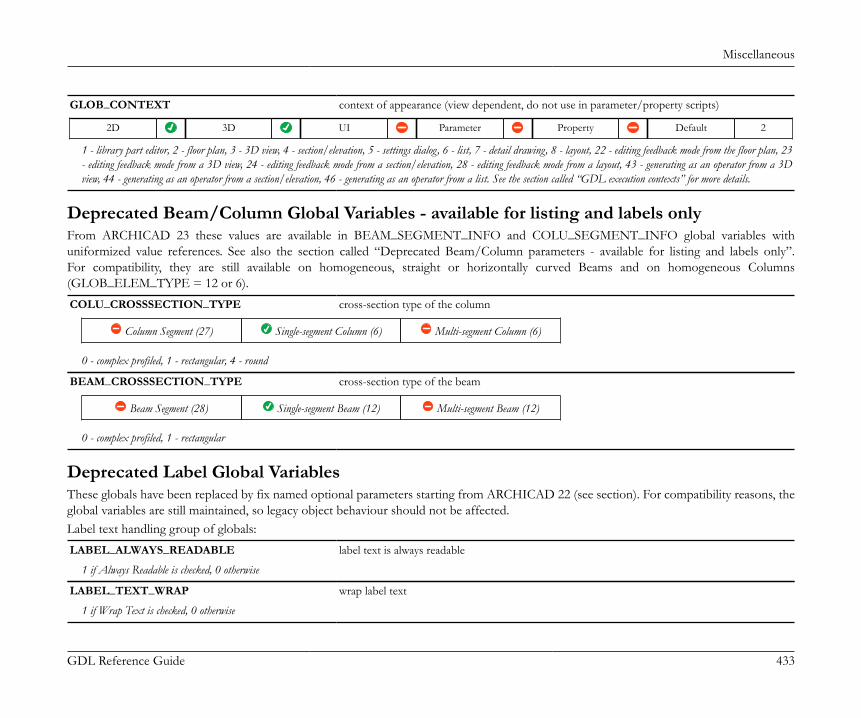
Miscellaneous
GDL Reference Guide 433
GLOB_CONTEXT context of appearance (view dependent, do not use in parameter/property scripts)
2D 3D UI Parameter Property Default 2
1 - library part editor, 2 - floor plan, 3 - 3D view, 4 - section/elevation, 5 - settings dialog, 6 - list, 7 - detail drawing, 8 - layout, 22 - editing feedback mode from the floor plan, 23- editing feedback mode from a 3D view, 24 - editing feedback mode from a section/elevation, 28 - editing feedback mode from a layout, 43 - generating as an operator from a 3Dview, 44 - generating as an operator from a section/elevation, 46 - generating as an operator from a list. See the section called “GDL execution contexts” for more details.
Deprecated Beam/Column Global Variables - available for listing and labels onlyFrom ARCHICAD 23 these values are available in BEAM_SEGMENT_INFO and COLU_SEGMENT_INFO global variables withuniformized value references. See also the section called “Deprecated Beam/Column parameters - available for listing and labels only”.For compatibility, they are still available on homogeneous, straight or horizontally curved Beams and on homogeneous Columns(GLOB_ELEM_TYPE = 12 or 6).COLU_CROSSSECTION_TYPE cross-section type of the column
Column Segment (27) Single-segment Column (6) Multi-segment Column (6)
0 - complex profiled, 1 - rectangular, 4 - round
BEAM_CROSSSECTION_TYPE cross-section type of the beam
Beam Segment (28) Single-segment Beam (12) Multi-segment Beam (12)
0 - complex profiled, 1 - rectangular
Deprecated Label Global VariablesThese globals have been replaced by fix named optional parameters starting from ARCHICAD 22 (see section). For compatibility reasons, theglobal variables are still maintained, so legacy object behaviour should not be affected.Label text handling group of globals:LABEL_ALWAYS_READABLE label text is always readable
1 if Always Readable is checked, 0 otherwise
LABEL_TEXT_WRAP wrap label text
1 if Wrap Text is checked, 0 otherwise

Miscellaneous
GDL Reference Guide 434
LABEL_TEXT_ALIGN text alignment
1 - left aligned, 2 - center aligned, 3 - right aligned, 4 - full justified
LABEL_TEXT_LEADING line spacing factor
LABEL_TEXT_WIDTH_FACT width factor
LABEL_TEXT_CHARSPACE_FACT spacing factor
LABEL_FONT_NAME font name
LABEL_TEXT_SIZE text size
LABEL_TEXT_PEN pen of the text
LABEL_TEXT_BG_PEN text box background pen
0 if opaque is off, the background pen index otherwise
LABEL_FONT_STYLE font style
0-normal, 1-bold, 2-italic, 4- underline
LABEL_FONT_STYLE2 font style in the settings dialog box
0 - normal, otherwise j1 + 2*j2 + 4*j3 + 32*j6 + 64*j7 + 128*j8, j1 - bold, j2 - italic, j3 - underline, j6 - superscript, j7 - subscript, j8 - strikethrough
Label pointer/frame handling group of globals:
LABEL_CUSTOM_ARROW use symbol arrow option on/off
1 if the Use symbol arrow checkbox is checked, 0 otherwise
LABEL_ARROW_LINETYPE line type of the line of the arrow
LABEL_ARROW_PEN pen of the arrow
LABEL_FRAME_ON label frame on/off
1 if the label frame is checked, 0 otherwise
LABEL_FRAME_OFFSET frame offset
LABEL_ANCHOR_POS label anchor position
0 - middle, 1 - top, 2 - bottom, 3 - bottom right
Miscellaneous
GDL Reference Guide 435
Deprecated Curtain Wall Frame Global Variable - available for listing and labels onlyFrom ARCHICAD 22 User-defined curtain wall frame classes has been introduced instead of the predefined classes. For compatibility reasons,the CWFRAME_CLASS global variable is still maintained.
CWFRAME_CLASS class of the frame
2 - boundary, 3 - otherCompatibility: up to ARCHICAD 21 the values can be 0 - mullion, 1 - transom, 2 - boundary, 3 - custom
Old Global VariablesOld global variable names can be used; however, the use of the new names is recommended. Each old global corresponds to a new variablewith a long name.

Miscellaneous
GDL Reference Guide 436
A_ GLOB_SCALEB_ GLOB_HSTORY_ELEVC_ WALL_THICKNESSD_ WALL_HEIGHTE_ WALL_SECT_PENF_ WALL_FILL_PENG_ WALL_MAT_AH_ WALL_MAT_BI_ WALL_MAT_EDGEJ_ GLOB_ELEVATIONK_ WIDO_SILLL_ SYMB_VIEW_PENM_ SYMB_MATN_ GLOB_FRAME_NRO_ GLOB_FIRST_FRAMEP_ GLOB_LAST_FRAMEQ_ GLOB_HSTORY_HEIGHTR_ WIDO_ORIG_DISTS_ GLOB_USER_1T_ GLOB_USER_2U_ GLOB_USER_3V_ GLOB_USER_4W_ GLOB_USER_5X_ GLOB_USER_6Y_ GLOB_USER_7Z_ GLOB_USER_8

Miscellaneous
GDL Reference Guide 437
A~ WALL_FILLB~ WIDO_RIGHT_JAMBC~ WIDO_THRES_DEPTHD~ WIDO_HEAD_DEPTHE~ WIDO_REVEAL_SIDEF~ WIDO_FRAME_THICKNESSG~ GLOB_USER_9H~ WIDO_POSITIONI~ GLOB_USER_10J~ WALL_RESOLK~ GLOB_EYEPOS_XL~ GLOB_EYEPOS_YM~ GLOB_EYEPOS_ZN~ GLOB_TARGPOS_XO~ GLOB_TARGPOS_YP~ GLOB_TARGPOS_ZQ~ GLOB_CSTORY_ELEVR~ GLOB_CSTORY_HEIGHTS~ GLOB_CH_STORY_DISTT~ GLOB_SCRIPT_TYPEU~ GLOB_NORTH_DIRV~ SYMB_MIRROREDW~ SYMB_ROTANGLEX~ SYMB_POS_XY~ SYMB_POS_YZ~ SYMB_POS_Z
FIX NAMED OPTIONAL PARAMETERS
Parameters set by ARCHICADThe new method of ARCHICAD for providing information is the method of fixed named optional parameters. If a given library part has aparameter matching a fix named optional parameter in name and in type, ARCHICAD sets its value according to its function.
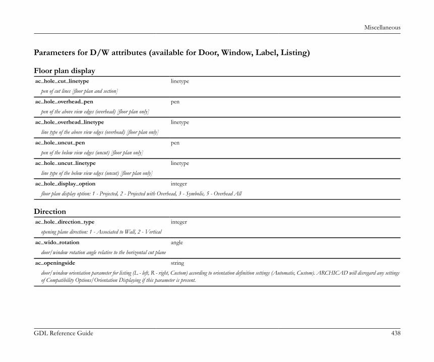
Miscellaneous
GDL Reference Guide 438
Parameters for D/W attributes (available for Door, Window, Label, Listing)
Floor plan displayac_hole_cut_linetype linetype
pen of cut lines [floor plan and section]
ac_hole_overhead_pen pen
pen of the above view edges (overhead) [floor plan only]
ac_hole_overhead_linetype linetype
line type of the above view edges (overhead) [floor plan only]
ac_hole_uncut_pen pen
pen of the below view edges (uncut) [floor plan only]
ac_hole_uncut_linetype linetype
line type of the below view edges (uncut) [floor plan only]
ac_hole_display_option integer
floor plan display option: 1 - Projected, 2 - Projected with Overhead, 3 - Symbolic, 5 - Overhead All
Directionac_hole_direction_type integer
opening plane direction: 1 - Associated to Wall, 2 - Vertical
ac_wido_rotation angle
door/window rotation angle relative to the horizontal cut plane
ac_openingside string
door/window orientation parameter for listing (L - left, R - right, Custom) according to orientation definition settings (Automatic, Custom). ARCHICAD will disregard any settingsof Compatibility Options/Orientation Displaying if this parameter is present.
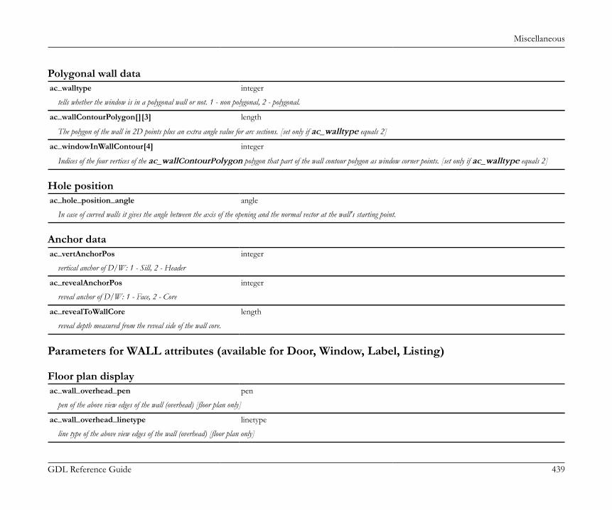
Miscellaneous
GDL Reference Guide 439
Polygonal wall dataac_walltype integer
tells whether the window is in a polygonal wall or not. 1 - non polygonal, 2 - polygonal.
ac_wallContourPolygon[][3] length
The polygon of the wall in 2D points plus an extra angle value for arc sections. [set only if ac_walltype equals 2]
ac_windowInWallContour[4] integer
Indices of the four vertices of the ac_wallContourPolygon polygon that part of the wall contour polygon as window corner points. [set only if ac_walltype equals 2]
Hole positionac_hole_position_angle angle
In case of curved walls it gives the angle between the axis of the opening and the normal vector at the wall's starting point.
Anchor dataac_vertAnchorPos integer
vertical anchor of D/W: 1 - Sill, 2 - Header
ac_revealAnchorPos integer
reveal anchor of D/W: 1 - Face, 2 - Core
ac_revealToWallCore length
reveal depth measured from the reveal side of the wall core.
Parameters for WALL attributes (available for Door, Window, Label, Listing)
Floor plan displayac_wall_overhead_pen pen
pen of the above view edges of the wall (overhead) [floor plan only]
ac_wall_overhead_linetype linetype
line type of the above view edges of the wall (overhead) [floor plan only]
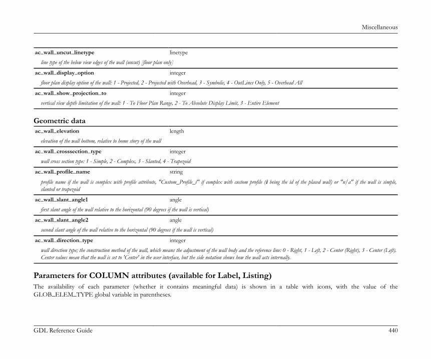
Miscellaneous
GDL Reference Guide 440
ac_wall_uncut_linetype linetype
line type of the below view edges of the wall (uncut) [floor plan only]
ac_wall_display_option integer
floor plan display option of the wall: 1 - Projected, 2 - Projected with Overhead, 3 - Symbolic, 4 - OutLines Only, 5 - Overhead All
ac_wall_show_projection_to integer
vertical view depth limitation of the wall: 1 - To Floor Plan Range, 2 - To Absolute Display Limit, 3 - Entire Element
Geometric dataac_wall_elevation length
elevation of the wall bottom, relative to home story of the wall
ac_wall_crosssection_type integer
wall cross section type: 1 - Simple, 2 - Complex, 3 - Slanted, 4 - Trapezoid
ac_wall_profile_name string
profile name if the wall is complex with profile attribute, "Custom_Profile_i" if complex with custom profile (i being the id of the placed wall) or "n/a" if the wall is simple,slanted or trapezoid
ac_wall_slant_angle1 angle
first slant angle of the wall relative to the horizontal (90 degrees if the wall is vertical)
ac_wall_slant_angle2 angle
second slant angle of the wall relative to the horizontal (90 degrees if the wall is vertical)
ac_wall_direction_type integer
wall direction type; the construction method of the wall, which means the adjustment of the wall body and the reference line: 0 - Right, 1 - Left, 2 - Center (Right), 3 - Center (Left).Center values mean that the wall is set to 'Center' in the user interface, but the side notation shows how the wall acts internally.
Parameters for COLUMN attributes (available for Label, Listing)The availability of each parameter (whether it contains meaningful data) is shown in a table with icons, with the value of theGLOB_ELEM_TYPE global variable in parentheses.
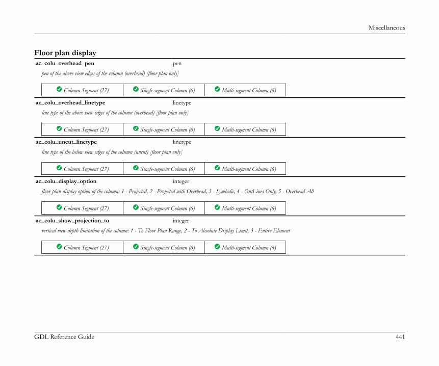
Miscellaneous
GDL Reference Guide 441
Floor plan displayac_colu_overhead_pen pen
pen of the above view edges of the column (overhead) [floor plan only]
Column Segment (27) Single-segment Column (6) Multi-segment Column (6)
ac_colu_overhead_linetype linetype
line type of the above view edges of the column (overhead) [floor plan only]
Column Segment (27) Single-segment Column (6) Multi-segment Column (6)
ac_colu_uncut_linetype linetype
line type of the below view edges of the column (uncut) [floor plan only]
Column Segment (27) Single-segment Column (6) Multi-segment Column (6)
ac_colu_display_option integer
floor plan display option of the column: 1 - Projected, 2 - Projected with Overhead, 3 - Symbolic, 4 - OutLines Only, 5 - Overhead All
Column Segment (27) Single-segment Column (6) Multi-segment Column (6)
ac_colu_show_projection_to integer
vertical view depth limitation of the column: 1 - To Floor Plan Range, 2 - To Absolute Display Limit, 3 - Entire Element
Column Segment (27) Single-segment Column (6) Multi-segment Column (6)

Miscellaneous
GDL Reference Guide 442
Geometric dataac_colu_profile_name string
profile name if the column is complex with profile attribute, "Custom_Profile_i" if complex with custom profile (i being the id of the placed column) or "n/a" if the column isrectangular or round
Column Segment (27) Single-segment Column (6) Multi-segment Column (6)
ac_colu_inclination angle
inclination angle of the column relative to the horizontal line
Column Segment (27) Single-segment Column (6) Multi-segment Column (6)
ac_colu_twist_angle angle
twist angle of the cross section
Column Segment (27) Single-segment Column (6) Multi-segment Column (6)
Parameters for BEAM attributes (available for Label, Listing)The availability of each parameter (whether it contains meaningful data) is shown in a table with icons, with the value of theGLOB_ELEM_TYPE global variable in parentheses.
Floor plan displayac_beam_overhead_pen pen
pen of the above view edges of the beam(overhead) [floor plan only]
Beam Segment (28) Single-segment Beam (12) Multi-segment Beam (12)
ac_beam_cut_linetype linetype
line type of the cut edges of the beam [not valid for complex profile]
Beam Segment (28) Single-segment Beam (12) Multi-segment Beam (12)

Miscellaneous
GDL Reference Guide 443
ac_beam_uncut_pen pen
pen of the below view edges of the beam (uncut) [floor plan only]
Beam Segment (28) Single-segment Beam (12) Multi-segment Beam (12)
ac_beam_uncut_linetype linetype
line type of the below view edges of the beam (uncut) [floor plan only]
Beam Segment (28) Single-segment Beam (12) Multi-segment Beam (12)
ac_beam_display_option integer
floor plan display option of the beam: 1 - Projected, 2 - Projected with Overhead, 3 - Symbolic, 4 - OutLines Only, 5 - Overhead All
Beam Segment (28) Single-segment Beam (12) Multi-segment Beam (12)
ac_beam_show_projection_to integer
vertical view depth limitation of the beam: 1 - To Floor Plan Range, 2 - To Absolute Display Limit, 3 - Entire Element
Beam Segment (28) Single-segment Beam (12) Multi-segment Beam (12)
Geometric dataac_beam_profile_name string
profile name if complex with profile attribute, "Custom_Profile_i" if complex with custom profile (i being the id of the placed beam) or "n/a" if the beam is rectangular
Beam Segment (28) Single-segment Beam (12) Multi-segment Beam (12)
ac_beam_inclination angle
inclination angle of the beam relative to the horizontal line
Beam Segment (28) Single-segment Beam (12) Multi-segment Beam (12)
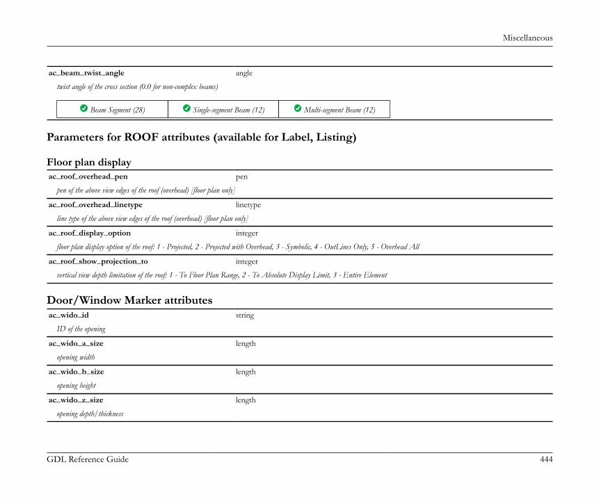
Miscellaneous
GDL Reference Guide 444
ac_beam_twist_angle angle
twist angle of the cross section (0.0 for non-complex beams)
Beam Segment (28) Single-segment Beam (12) Multi-segment Beam (12)
Parameters for ROOF attributes (available for Label, Listing)
Floor plan displayac_roof_overhead_pen pen
pen of the above view edges of the roof (overhead) [floor plan only]
ac_roof_overhead_linetype linetype
line type of the above view edges of the roof (overhead) [floor plan only]
ac_roof_display_option integer
floor plan display option of the roof: 1 - Projected, 2 - Projected with Overhead, 3 - Symbolic, 4 - OutLines Only, 5 - Overhead All
ac_roof_show_projection_to integer
vertical view depth limitation of the roof: 1 - To Floor Plan Range, 2 - To Absolute Display Limit, 3 - Entire Element
Door/Window Marker attributesac_wido_id string
ID of the opening
ac_wido_a_size length
opening width
ac_wido_b_size length
opening height
ac_wido_z_size length
opening depth/thickness

Miscellaneous
GDL Reference Guide 445
ac_glob_elevation length
elevation of the base line of the opening
ac_wido_subfl_thickness length
height of the subfloor wall part
ac_wido_reveal_side boolean
legacy opening reveal side value, use ac_wido_reveal_side_2 instead
ac_wido_reveal_side_2 boolean
reveal side, the value of the WIDO_REVEAL_SIDE global variable set for the opening
ac_wido_mirrored boolean
mirrored state of the opening
ac_wall_thickness length
thickness of the wall at the origin of the opening
ac_wido_oversize_l length
left opening oversize
ac_wido_oversize_r length
right opening oversize
ac_wido_oversize_t length
top opening oversize
ac_wido_oversize_b length
bottom opening oversize
ac_wido_orientation string
marker position: "L" - Left, "R" - right, or any custom value set in the Details window of the library part editor according to the current mirrored state
ac_wido_type integer
1 - Door, 2 - Window

Miscellaneous
GDL Reference Guide 446
ac_symb_rotangle angle
opening rotation in the wall
ac_sill_to_curr_story length
sill height of the opening measured from the start of the story linked to the window sill
ac_sill_to_anchor_level length
sill height of the opening measured from the level of the anchor point; the anchor point may be the bottom of the wall or the selected story, accordingly
Detail/Worksheet Marker attributesac_showboundary boolean
Marker boundary polygon state. 0 - boundary off, 1 - boundary on.
Drawing Title attributesac_drawingName string
Name of the drawing.
ac_drawingNumber string
ID of the drawing.
ac_sourceFileName string
Name of the drawing source file (if the drawing comes from an external file).
ac_sourceFilePath string
Path of the drawing source file (if the drawing comes from an external file).
ac_drawingScale string
Drawing scale set for the drawing.
ac_magnification real number
Magnification percentage set for the drawing.
ac_originalDrawingScale string
Drawing scale of the originating view.

Miscellaneous
GDL Reference Guide 447
ac_enableBackReference boolean
Back referencing is enabled for the drawing.
ac_backReferenceGUIDList string array
List of referred layout GUIDs. They can be used in autotext outputs.
ac_showDrawingReferences boolean
Show back references.
General running contextac_programVersion integer
This parameter contains the version of ARCHICAD executing the library part's scripts.
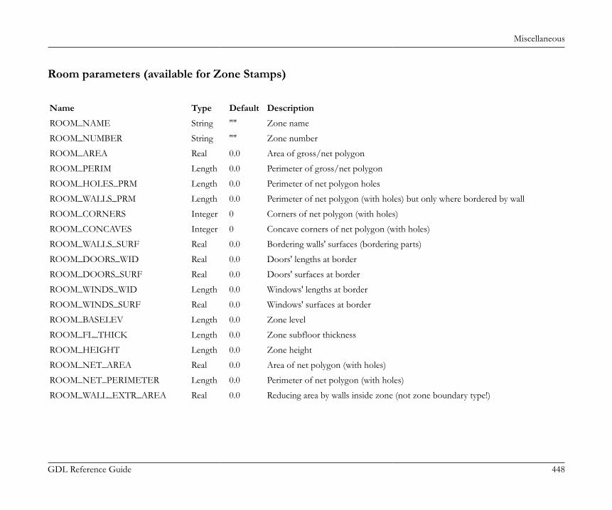
Miscellaneous
GDL Reference Guide 448
Room parameters (available for Zone Stamps)
Name Type Default Description
ROOM_NAME String "" Zone name
ROOM_NUMBER String "" Zone number
ROOM_AREA Real 0.0 Area of gross/net polygon
ROOM_PERIM Length 0.0 Perimeter of gross/net polygon
ROOM_HOLES_PRM Length 0.0 Perimeter of net polygon holes
ROOM_WALLS_PRM Length 0.0 Perimeter of net polygon (with holes) but only where bordered by wall
ROOM_CORNERS Integer 0 Corners of net polygon (with holes)
ROOM_CONCAVES Integer 0 Concave corners of net polygon (with holes)
ROOM_WALLS_SURF Real 0.0 Bordering walls' surfaces (bordering parts)
ROOM_DOORS_WID Real 0.0 Doors' lengths at border
ROOM_DOORS_SURF Real 0.0 Doors' surfaces at border
ROOM_WINDS_WID Length 0.0 Windows' lengths at border
ROOM_WINDS_SURF Real 0.0 Windows' surfaces at border
ROOM_BASELEV Length 0.0 Zone level
ROOM_FL_THICK Length 0.0 Zone subfloor thickness
ROOM_HEIGHT Length 0.0 Zone height
ROOM_NET_AREA Real 0.0 Area of net polygon (with holes)
ROOM_NET_PERIMETER Length 0.0 Perimeter of net polygon (with holes)
ROOM_WALL_EXTR_AREA Real 0.0 Reducing area by walls inside zone (not zone boundary type!)

Miscellaneous
GDL Reference Guide 449
Name Type Default Description
ROOM_COLUMN_EXTR_AREA Real 0.0 Reducing area by columns inside zone (not zone boundary type!)
ROOM_FILL_EXTR_AREA Real 0.0 Reducing area by hatches inside zone (considering percentage!)
ROOM_LOW_EXTR_AREA Real 0.0 Reducing area by low parts (trimmed) (considering preferences!)
ROOM_TOTAL_EXTR_AREA Real 0.0 Sum of previous values (total extraction)
ROOM_REDUCED_AREA Real 0.0 ROOM_NET_AREA - ROOM_TOTAL_EXTR_AREA
ROOM_AREA_FACTOR Real 0.0 1 - Reduced_by_in_dialog / 100
ROOM_CALC_AREA Real 0.0 ROOM_REDUCED_AREA * ROOM_AREA_FACTOR
ROOM_VOLUME Real 0.0 Calculated from trimmed room upon net polygon
ROOM_BOUNDARY_SURF Real 0.0 Surface of boundary side pages
ROOM_TOP_SURFACE Real 0.0 Surface of zone top
ROOM_BOT_SURFACE Real 0.0 Surface of zone bottom
ROOM_ROOF_TOP_SURF Real 0.0 Surface of zone top where trimmed by a Roof
ROOM_ROOF_BOT_SURF Real 0.0 Surface of zone bottom where trimmed by a Roof
ROOM_SLAB_TOP_SURF Real 0.0 Surface of zone top where trimmed by a Slab
ROOM_SLAB_BOT_SURF Real 0.0 Surface of zone bottom where trimmed by a Slab
ROOM_BEAM_TOP_SURF Real 0.0 Surface of zone top where trimmed by a Beam
ROOM_BEAM_BOT_SURF Real 0.0 Surface of zone bottom where trimmed by a Beam
ROOM_WALL_IN_TOP_SURF Real 0.0 Sum of top surfaces of wall insets (or recess or niche)
ROOM_WALL_IN_BACK_SURF Real 0.0 Sum of back surfaces of wall insets (facing to window)
ROOM_WALL_IN_SIDE_SURF Real 0.0 Sum of side surfaces of wall insets
ROOM_POLY_STATUS Integer 0 0:manual, 1:Auto, 2:Auto-refline

Miscellaneous
GDL Reference Guide 450
Stair related parameters
Flight / Landing Side Supported subtypesac_beamPlacement integer
This parameter reflects which side of the stair the stringer is placed. Compatibility: introduced in ARCHICAD 21.• 0 - Left (when viewed as going up the stair)• 1 - Right
Riser Component subtypeac_RiserPosition integer
This parameter reflects the current settings of riser and tread connections:• 0 - Riser on Tread OFF• 1 - Riser on Tread ON
Stair 2D Component subtypesac_treadClassifications integer - array
Type of each tread (indexed from bottom upwards):• 0 - Tread• 1 - Landing
Parameters set/read by ARCHICADARCHICAD can synchronize values with library parts through parameters with predefined name and function. The list of such parametersfollows below.
Stair related parameters
Structure subtypeac_stairStructureWidth length
Width of the structure stringer, as set in the Stair Settings. Value is 0 for beam structure type.
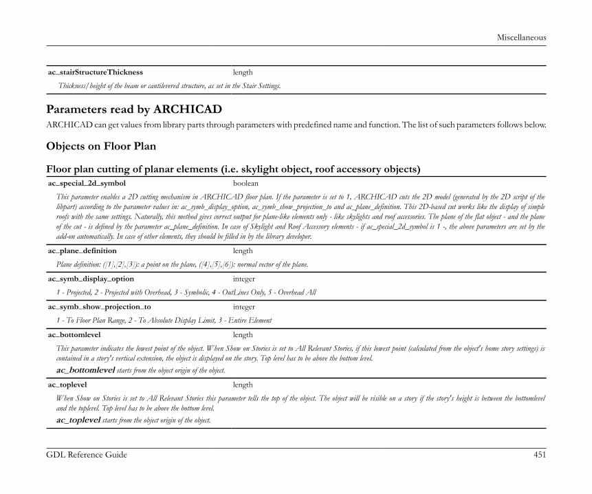
Miscellaneous
GDL Reference Guide 451
ac_stairStructureThickness length
Thickness/height of the beam or cantilevered structure, as set in the Stair Settings.
Parameters read by ARCHICADARCHICAD can get values from library parts through parameters with predefined name and function. The list of such parameters follows below.
Objects on Floor Plan
Floor plan cutting of planar elements (i.e. skylight object, roof accessory objects)ac_special_2d_symbol boolean
This parameter enables a 2D cutting mechanism in ARCHICAD floor plan. If the parameter is set to 1, ARCHICAD cuts the 2D model (generated by the 2D script of thelibpart) according to the parameter values in: ac_symb_display_option, ac_symb_show_projection_to and ac_plane_definition. This 2D-based cut works like the display of simpleroofs with the same settings. Naturally, this method gives correct output for plane-like elements only - like skylights and roof accessories. The plane of the flat object - and the planeof the cut - is defined by the parameter ac_plane_definition. In case of Skylight and Roof Accessory elements - if ac_special_2d_symbol is 1 -, the above parameters are set by theadd-on automatically. In case of other elements, they should be filled in by the library developer.
ac_plane_definition length
Plane definition: ([1],[2],[3]): a point on the plane, ([4],[5],[6]): normal vector of the plane.
ac_symb_display_option integer
1 - Projected, 2 - Projected with Overhead, 3 - Symbolic, 4 - OutLines Only, 5 - Overhead All
ac_symb_show_projection_to integer
1 - To Floor Plan Range, 2 - To Absolute Display Limit, 3 - Entire Element
ac_bottomlevel length
This parameter indicates the lowest point of the object. When Show on Stories is set to All Relevant Stories, if this lowest point (calculated from the object's home story settings) iscontained in a story's vertical extension, the object is displayed on the story. Top level has to be above the bottom level.ac_bottomlevel starts from the object origin of the object.
ac_toplevel length
When Show on Stories is set to All Relevant Stories this parameter tells the top of the object. The object will be visible on a story if the story's height is between the bottomleveland the toplevel. Top level has to be above the bottom level.ac_toplevel starts from the object origin of the object.
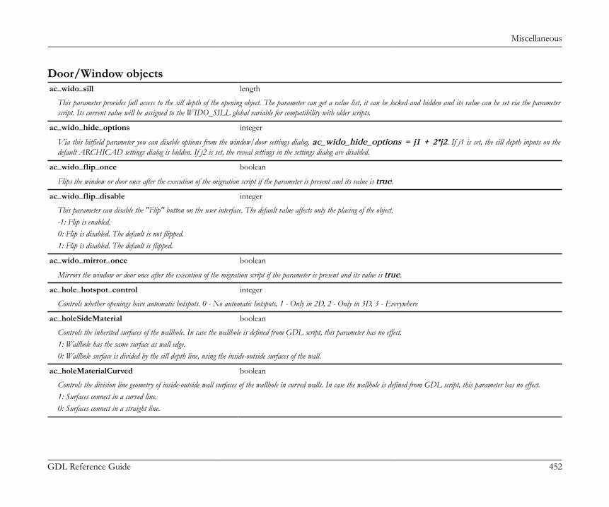
Miscellaneous
GDL Reference Guide 452
Door/Window objectsac_wido_sill length
This parameter provides full access to the sill depth of the opening object. The parameter can get a value list, it can be locked and hidden and its value can be set via the parameterscript. Its current value will be assigned to the WIDO_SILL global variable for compatibility with older scripts.
ac_wido_hide_options integer
Via this bitfield parameter you can disable options from the window/door settings dialog. ac_wido_hide_options = j1 + 2*j2. If j1 is set, the sill depth inputs on thedefault ARCHICAD settings dialog is hidden. If j2 is set, the reveal settings in the settings dialog are disabled.
ac_wido_flip_once boolean
Flips the window or door once after the execution of the migration script if the parameter is present and its value is true.
ac_wido_flip_disable integer
This parameter can disable the "Flip" button on the user interface. The default value affects only the placing of the object.-1: Flip is enabled.0: Flip is disabled. The default is not flipped.1: Flip is disabled. The default is flipped.
ac_wido_mirror_once boolean
Mirrors the window or door once after the execution of the migration script if the parameter is present and its value is true.
ac_hole_hotspot_control integer
Controls whether openings have automatic hotspots. 0 - No automatic hotspots, 1 - Only in 2D, 2 - Only in 3D, 3 - Everywhere
ac_holeSideMaterial boolean
Controls the inherited surfaces of the wallhole. In case the wallhole is defined from GDL script, this parameter has no effect.1: Wallhole has the same surface as wall edge.0: Wallhole surface is divided by the sill depth line, using the inside-outside surfaces of the wall.
ac_holeMaterialCurved boolean
Controls the division line geometry of inside-outside wall surfaces of the wallhole in curved walls. In case the wallhole is defined from GDL script, this parameter has no effect.1: Surfaces connect in a curved line.0: Surfaces connect in a straight line.
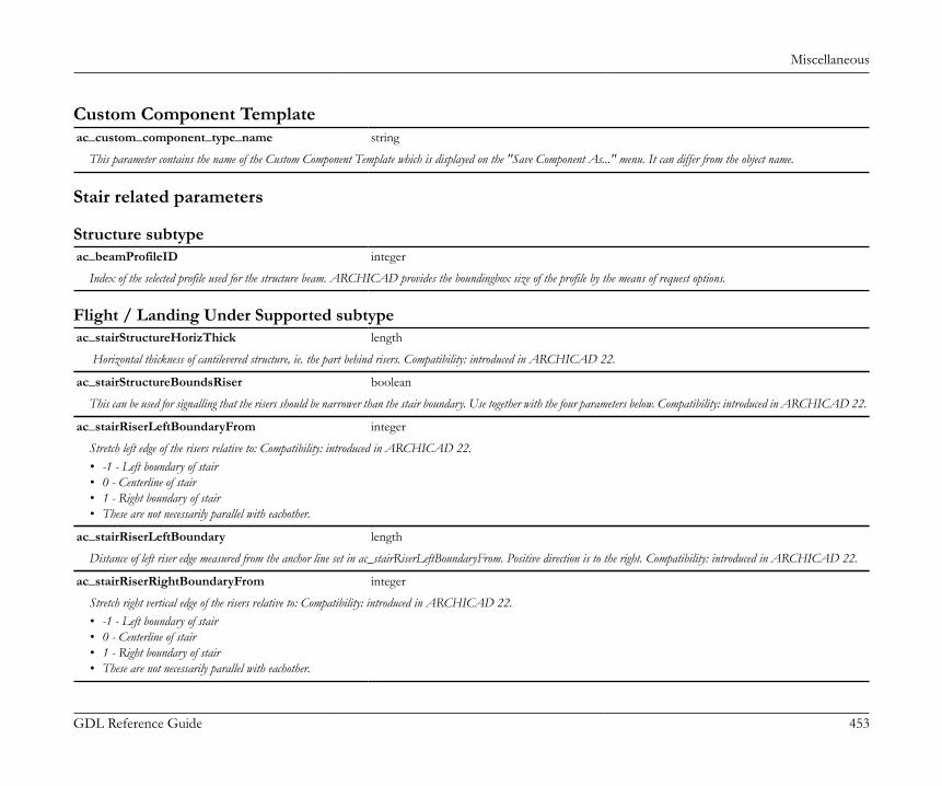
Miscellaneous
GDL Reference Guide 453
Custom Component Templateac_custom_component_type_name string
This parameter contains the name of the Custom Component Template which is displayed on the "Save Component As..." menu. It can differ from the object name.
Stair related parameters
Structure subtypeac_beamProfileID integer
Index of the selected profile used for the structure beam. ARCHICAD provides the boundingbox size of the profile by the means of request options.
Flight / Landing Under Supported subtypeac_stairStructureHorizThick length
Horizontal thickness of cantilevered structure, ie. the part behind risers. Compatibility: introduced in ARCHICAD 22.
ac_stairStructureBoundsRiser boolean
This can be used for signalling that the risers should be narrower than the stair boundary. Use together with the four parameters below. Compatibility: introduced in ARCHICAD 22.
ac_stairRiserLeftBoundaryFrom integer
Stretch left edge of the risers relative to: Compatibility: introduced in ARCHICAD 22.• -1 - Left boundary of stair• 0 - Centerline of stair• 1 - Right boundary of stair• These are not necessarily parallel with eachother.
ac_stairRiserLeftBoundary length
Distance of left riser edge measured from the anchor line set in ac_stairRiserLeftBoundaryFrom. Positive direction is to the right. Compatibility: introduced in ARCHICAD 22.
ac_stairRiserRightBoundaryFrom integer
Stretch right vertical edge of the risers relative to: Compatibility: introduced in ARCHICAD 22.• -1 - Left boundary of stair• 0 - Centerline of stair• 1 - Right boundary of stair• These are not necessarily parallel with eachother.

Miscellaneous
GDL Reference Guide 454
ac_stairRiserRightBoundary length
Distance of right riser edge measured from the anchor line set in ac_stairRiserRightBoundaryFrom. Positive direction is to the right. Compatibility: introduced in ARCHICAD 22.
Flight Under Supported Cantilever / Landing Cantilever Supported subtypesac_stairWallFixingWidthLeft length
The depth of the cantilever in the wall (on the left side of the stair). Used at drawing the 2D symbol of the cantilever: any drawing beyond this will be cropped. Compatibility:introduced in ARCHICAD 21.
ac_stairWallFixingWidthRight length
The depth of the cantilever in the wall (on the right side of the stair). Used at drawing the 2D symbol of the cantilever: any drawing beyond this will be cropped. Compatibility:introduced in ARCHICAD 21.
Railing related parameters
Railing Panel Component subtypeac_panelThickness length
Thickness of panel section in the railing. Parameter value should be kept consistent with the model size via Parameter script.
Railing Rail Component subtypeac_railWidth length
Absolute width of the rail section mesured on a plane perpendicular to rail axis. Parameter value should be kept consistent with the model size via Parameter script.
ac_railHeight length
Absolute height of the rail section mesured on a plane perpendicular to rail axis. Parameter value should be kept consistent with the model size via Parameter script.
ac_rail_boundingbox_left length
Relative distance of the rail section bounding box left side measured from the rail section axis (RAIL_POLYLINE_GEOMETRY), on a plane perpendicular to rail axis, lookingin the direction of the rail. Parameter value should be kept consistent with the model size via Parameter script. Used for section bounding box offset of the component axis.
ac_rail_boundingbox_right length
Relative distance of the rail section bounding box right side measured from the rail section axis (RAIL_POLYLINE_GEOMETRY), on a plane perpendicular to rail axis,looking in the direction of the rail. Parameter value should be kept consistent with the model size via Parameter script. Used for section bounding box offset of the component axis.

Miscellaneous
GDL Reference Guide 455
ac_rail_boundingbox_top length
Relative distance of the rail section bounding box top measured from the rail section axis (RAIL_POLYLINE_GEOMETRY), on a plane perpendicular to rail axis, looking inthe direction of the rail. Parameter value should be kept consistent with the model size via Parameter script. Used for section bounding box offset of the component axis.
ac_rail_boundingbox_bottom length
Relative distance of the rail section bounding box bottom measured from the rail section axis (RAIL_POLYLINE_GEOMETRY), on a plane perpendicular to rail axis, lookingin the direction of the rail. Parameter value should be kept consistent with the model size via Parameter script. Used for section bounding box offset of the component axis.
ac_railProfileID integer
Index of the selected profile used for the rail. ARCHICAD provides the boundingbox size of the profile by the means of request options.
Railing Post Component subtypeac_postWidth length
Absolute width of the post section mesured on a plane perpendicular to post axis. Parameter value should be kept consistent with the model size via Parameter script.
ac_postHeight length
Absolute height of the post section mesured on a plane perpendicular to post axis. Parameter value should be kept consistent with the model size via Parameter script.
ac_post_boundingbox_left length
Relative distance of the post section bounding box left side measured from the post section axis, on a plane perpendicular to post axis, left means the direction of the beginning of thereference line, looking from the inside. Parameter value should be kept consistent with the model size via Parameter script. Used for section bounding box offset of the component axis.
ac_post_boundingbox_right length
Relative distance of the post section bounding box right side measured from the post section axis, on a plane perpendicular to post axis, right means the direction of the end of thereference line, looking from the inside. Parameter value should be kept consistent with the model size via Parameter script. Used for section bounding box offset of the component axis.
ac_post_boundingbox_inside length
Relative distance of the post section bounding box measured horizontally from the post section axis, on a plane perpendicular to post axis, inside meaning the side a right-side handrailis placed on. Parameter value should be kept consistent with the model size via Parameter script. Used for section bounding box offset of the component axis.
ac_post_boundingbox_outside length
Relative distance of the post section bounding box measured horizontally from the post section axis, on a plane perpendicular to post axis, outside meaning the opposite side a right-side handrail is placed on. Parameter value should be kept consistent with the model size via Parameter script. Used for section bounding box offset of the component axis.
ac_postProfileID integer
Index of the selected profile used for the post. ARCHICAD provides the boundingbox size of the profile by the means of request options.
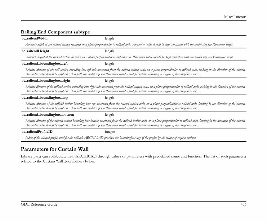
Miscellaneous
GDL Reference Guide 456
Railing End Component subtypeac_railendWidth length
Absolute width of the railend section mesured on a plane perpendicular to railend axis. Parameter value should be kept consistent with the model size via Parameter script.
ac_railendHeight length
Absolute height of the railend section mesured on a plane perpendicular to railend axis. Parameter value should be kept consistent with the model size via Parameter script.
ac_railend_boundingbox_left length
Relative distance of the rail section bounding box left side measured from the railend section axis, on a plane perpendicular to railend axis, looking in the direction of the railend.Parameter value should be kept consistent with the model size via Parameter script. Used for section bounding box offset of the component axis.
ac_railend_boundingbox_right length
Relative distance of the railend section bounding box right side measured from the railend section axis, on a plane perpendicular to railend axis, looking in the direction of the railend.Parameter value should be kept consistent with the model size via Parameter script. Used for section bounding box offset of the component axis.
ac_railend_boundingbox_top length
Relative distance of the railend section bounding box top measured from the railend section axis, on a plane perpendicular to railend axis, looking in the direction of the railend.Parameter value should be kept consistent with the model size via Parameter script. Used for section bounding box offset of the component axis.
ac_railend_boundingbox_bottom length
Relative distance of the railend section bounding box bottom measured from the railend section axis, on a plane perpendicular to railend axis, looking in the direction of the railend.Parameter value should be kept consistent with the model size via Parameter script. Used for section bounding box offset of the component axis.
ac_railendProfileID integer
Index of the selected profile used for the railend. ARCHICAD provides the boundingbox size of the profile by the means of request options.
Parameters for Curtain WallLibrary parts can collaborate with ARCHICAD through values of parameters with predefined name and function. The list of such parametersrelated to the Curtain Wall Tool follows below.
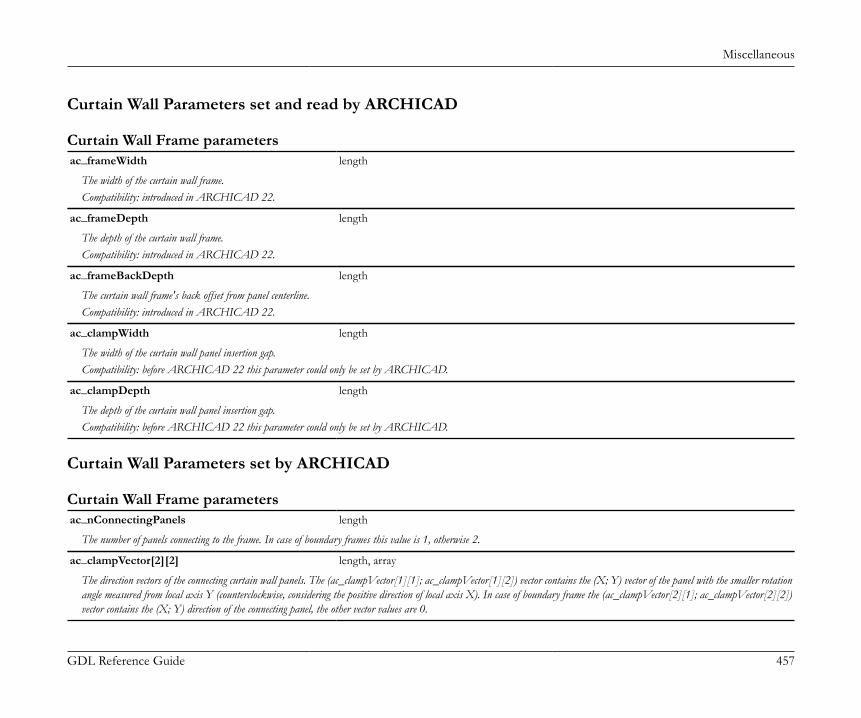
Miscellaneous
GDL Reference Guide 457
Curtain Wall Parameters set and read by ARCHICAD
Curtain Wall Frame parametersac_frameWidth length
The width of the curtain wall frame.Compatibility: introduced in ARCHICAD 22.
ac_frameDepth length
The depth of the curtain wall frame.Compatibility: introduced in ARCHICAD 22.
ac_frameBackDepth length
The curtain wall frame's back offset from panel centerline.Compatibility: introduced in ARCHICAD 22.
ac_clampWidth length
The width of the curtain wall panel insertion gap.Compatibility: before ARCHICAD 22 this parameter could only be set by ARCHICAD.
ac_clampDepth length
The depth of the curtain wall panel insertion gap.Compatibility: before ARCHICAD 22 this parameter could only be set by ARCHICAD.
Curtain Wall Parameters set by ARCHICAD
Curtain Wall Frame parametersac_nConnectingPanels length
The number of panels connecting to the frame. In case of boundary frames this value is 1, otherwise 2.
ac_clampVector[2][2] length, array
The direction vectors of the connecting curtain wall panels. The (ac_clampVector[1][1]; ac_clampVector[1][2]) vector contains the (X; Y) vector of the panel with the smaller rotationangle measured from local axis Y (counterclockwise, considering the positive direction of local axis X). In case of boundary frame the (ac_clampVector[2][1]; ac_clampVector[2][2])vector contains the (X; Y) direction of the connecting panel, the other vector values are 0.
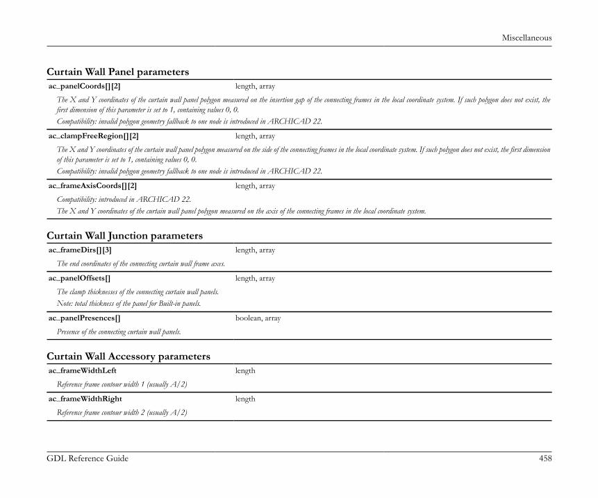
Miscellaneous
GDL Reference Guide 458
Curtain Wall Panel parametersac_panelCoords[][2] length, array
The X and Y coordinates of the curtain wall panel polygon measured on the insertion gap of the connecting frames in the local coordinate system. If such polygon does not exist, thefirst dimension of this parameter is set to 1, containing values 0, 0.Compatibility: invalid polygon geometry fallback to one node is introduced in ARCHICAD 22.
ac_clampFreeRegion[][2] length, array
The X and Y coordinates of the curtain wall panel polygon measured on the side of the connecting frames in the local coordinate system. If such polygon does not exist, the first dimensionof this parameter is set to 1, containing values 0, 0.Compatibility: invalid polygon geometry fallback to one node is introduced in ARCHICAD 22.
ac_frameAxisCoords[][2] length, array
Compatibility: introduced in ARCHICAD 22.The X and Y coordinates of the curtain wall panel polygon measured on the axis of the connecting frames in the local coordinate system.
Curtain Wall Junction parametersac_frameDirs[][3] length, array
The end coordinates of the connecting curtain wall frame axes.
ac_panelOffsets[] length, array
The clamp thicknesses of the connecting curtain wall panels.Note: total thickness of the panel for Built-in panels.
ac_panelPresences[] boolean, array
Presence of the connecting curtain wall panels.
Curtain Wall Accessory parametersac_frameWidthLeft length
Reference frame contour width 1 (usually A/2)
ac_frameWidthRight length
Reference frame contour width 2 (usually A/2)
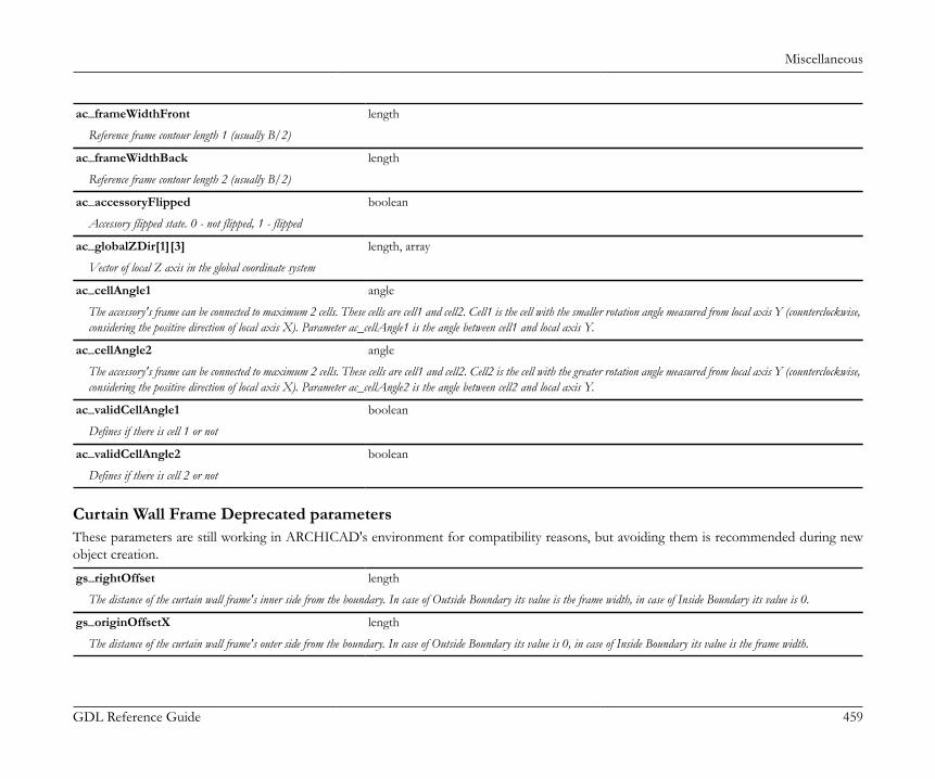
Miscellaneous
GDL Reference Guide 459
ac_frameWidthFront length
Reference frame contour length 1 (usually B/2)
ac_frameWidthBack length
Reference frame contour length 2 (usually B/2)
ac_accessoryFlipped boolean
Accessory flipped state. 0 - not flipped, 1 - flipped
ac_globalZDir[1][3] length, array
Vector of local Z axis in the global coordinate system
ac_cellAngle1 angle
The accessory's frame can be connected to maximum 2 cells. These cells are cell1 and cell2. Cell1 is the cell with the smaller rotation angle measured from local axis Y (counterclockwise,considering the positive direction of local axis X). Parameter ac_cellAngle1 is the angle between cell1 and local axis Y.
ac_cellAngle2 angle
The accessory's frame can be connected to maximum 2 cells. These cells are cell1 and cell2. Cell2 is the cell with the greater rotation angle measured from local axis Y (counterclockwise,considering the positive direction of local axis X). Parameter ac_cellAngle2 is the angle between cell2 and local axis Y.
ac_validCellAngle1 boolean
Defines if there is cell 1 or not
ac_validCellAngle2 boolean
Defines if there is cell 2 or not
Curtain Wall Frame Deprecated parametersThese parameters are still working in ARCHICAD's environment for compatibility reasons, but avoiding them is recommended during newobject creation.
gs_rightOffset length
The distance of the curtain wall frame's inner side from the boundary. In case of Outside Boundary its value is the frame width, in case of Inside Boundary its value is 0.
gs_originOffsetX length
The distance of the curtain wall frame's outer side from the boundary. In case of Outside Boundary its value is 0, in case of Inside Boundary its value is the frame width.

Miscellaneous
GDL Reference Guide 460
gs_frontOffset length
The distance of the curtain wall frame's front side from the centerline of the panel.
gs_originOffsetY length
The distance of the curtain wall frame's back side from the centerline of the panel.
ac_topConnPlane[4] length, array
The top cutplane position of the frame, defined in the local coordinate system of the library part.ac_topConnPlane[1]: X component of the normal vector of top cutplaneac_topConnPlane[2]: Y component of the normal vector of top cutplaneac_topConnPlane[3]: Z component of the normal vector of top cutplaneac_topConnPlane[4]: distance of top cutplane from frame origo
ac_bottomConnplane[4] length, array
The bottom cutplane position of the frame, defined in the local coordinate system of the library part.ac_bottomConnplane[1]: X component of the normal vector of bottom cutplaneac_bottomConnplane[2]: Y component of the normal vector of bottom cutplaneac_bottomConnplane[3]: Z component of the normal vector of bottom cutplaneac_bottomConnplane[4]: distance of bottom cutplane from frame origo
Curtain Wall Parameters read by ARCHICAD
Curtain Wall Panel and Frame parametersAC_AutoSchematicModel boolean
Controls whether the Schematic representation of the Curtain Wall Panel or Frame set at Model View Options / Curtain Wall Options is handled by ARCHICAD.Compatibility: introduced in ARCHICAD 22.
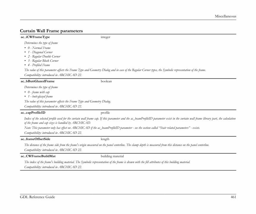
Miscellaneous
GDL Reference Guide 461
Curtain Wall Frame parametersac_iCWFrameType integer
Determines the type of frame• 0 - Normal Frame• 1 - Diagonal Corner• 2 - Regular Double Corner• 3 - Regular Block Corner• 4 - Profiled FrameThe value of this parameter affects the Frame Type and Geometry Dialog and in case of the Regular Corner types, the Symbolic representation of the frame.Compatibility: introduced in ARCHICAD 22.
ac_bButtGlazedFrame boolean
Determines the type of frame• 0 - frame with cap• 1 - butt-glazed frameThe value of this parameter affects the Frame Type and Geometry Dialog.Compatibility: introduced in ARCHICAD 22.
ac_capProfileID profile
Index of the selected profile used for the curtain wall frame cap. If this parameter and the ac_beamProfileID parameter exist in the curtain wall frame library part, the calculationof the frame and cap sizes is handled by ARCHICAD.Note: This parameter only has effect on ARCHICAD if the ac_beamProfileID parameter - see the section called “Stair related parameters” - exists.Compatibility: introduced in ARCHICAD 22.
ac_frameOffsetSide length
The distance of the frame side from the frame's origin measured on the panel centerline. The clamp depth is measured from this distance on the panel centerline.Compatibility: introduced in ARCHICAD 22.
ac_CWFrameBuildMat building material
The index of the frame's building material. The Symbolic representation of the frame is drawn with the fill attributes of this building material.Compatibility: introduced in ARCHICAD 22.
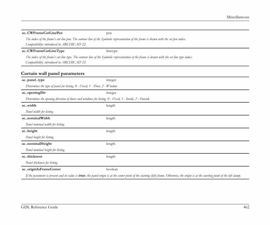
Miscellaneous
GDL Reference Guide 462
ac_CWFrameCutLinePen pen
The index of the frame's cut line pen. The contour line of the Symbolic representation of the frame is drawn with the set pen index.Compatibility: introduced in ARCHICAD 22.
ac_CWFrameCutLineType linetype
The index of the frame's cut line type. The contour line of the Symbolic representation of the frame is drawn with the set line type index.Compatibility: introduced in ARCHICAD 22.
Curtain wall panel parametersac_panel_type integer
Determines the type of panel for listing. 0 - Fixed, 1 - Door, 2 - Window
ac_openingDir integer
Determines the opening direction of doors and windows for listing. 0 - Fixed, 1 - Inside, 2 - Outside
ac_width length
Panel width for listing.
ac_nominalWidth length
Panel nominal width for listing.
ac_height length
Panel height for listing.
ac_nominalHeight length
Panel nominal height for listing.
ac_thickness length
Panel thickness for listing.
ac_originIsFrameCenter boolean
If the parameter is present and its value is true, the panel origin is at the center point of the starting (left) frame. Otherwise, the origin is at the starting point of the left clamp.

Miscellaneous
GDL Reference Guide 463
ac_aSizeIsWithClamp boolean
If the parameter is present and its value is true, ARCHICAD sets the A size as the distance between the frames plus the clamps' size. Otherwise, the A size is measured betweenthe frames.
Parameters for add-onsAdd-ons can get values from library parts through parameters with predefined name and function. The list of such parameters related toARCHICAD package add-ons follows below.
Parameters of Skylight add-on
Hole edge cut manipulationac_edge_lower_type integer
Cut type of the lower edge: 0 - Vertical, 1 - Perpendicular, 2 - Horizontal, 3 - Custom
ac_edge_lower_angle angle
Angle of the cut of the lower edge, if ac_edge_lower_type is 3. The value range is [1-179] degrees, 90 is the perpendicular case.
ac_edge_upper_type integer
Cut type of the upper edge: 0 - Vertical, 1 - Perpendicular, 2 - Horizontal, 3 - Custom
ac_edge_upper_angle angle
Angle of the cut of the upper edge, if ac_edge_upper_type is 3. The value range is [1-179] degrees, 90 is the perpendicular case.
Parameters of Corner Window add-on
Basic parameters of Corner Window objectsac_cw_function boolean
Window place mode, controlled by the add-on. 0 - Window, 1 - Corner window
ac_corner_window boolean
Corner window mode selector, controlled by the object. 0 - Disable corner window mode, 1 - Enable corner window mode
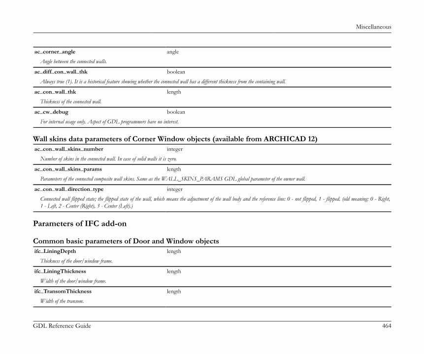
Miscellaneous
GDL Reference Guide 464
ac_corner_angle angle
Angle between the connected walls.
ac_diff_con_wall_thk boolean
Always true (1). It is a historical feature showing whether the connected wall has a different thickness from the containing wall.
ac_con_wall_thk length
Thickness of the connected wall.
ac_cw_debug boolean
For internal usage only. Aspect of GDL programmers have no interest.
Wall skins data parameters of Corner Window objects (available from ARCHICAD 12)ac_con_wall_skins_number integer
Number of skins in the connected wall. In case of solid walls it is zero.
ac_con_wall_skins_params length
Parameters of the connected composite wall skins. Same as the WALL_SKINS_PARAMS GDL global parameter of the owner wall.
ac_con_wall_direction_type integer
Connected wall flipped state; the flipped state of the wall, which means the adjustment of the wall body and the reference line: 0 - not flipped, 1 - flipped. (old meaning: 0 - Right,1 - Left, 2 - Center (Right), 3 - Center (Left).)
Parameters of IFC add-on
Common basic parameters of Door and Window objectsifc_LiningDepth length
Thickness of the door/window frame.
ifc_LiningThickness length
Width of the door/window frame.
ifc_TransomThickness length
Width of the transom.
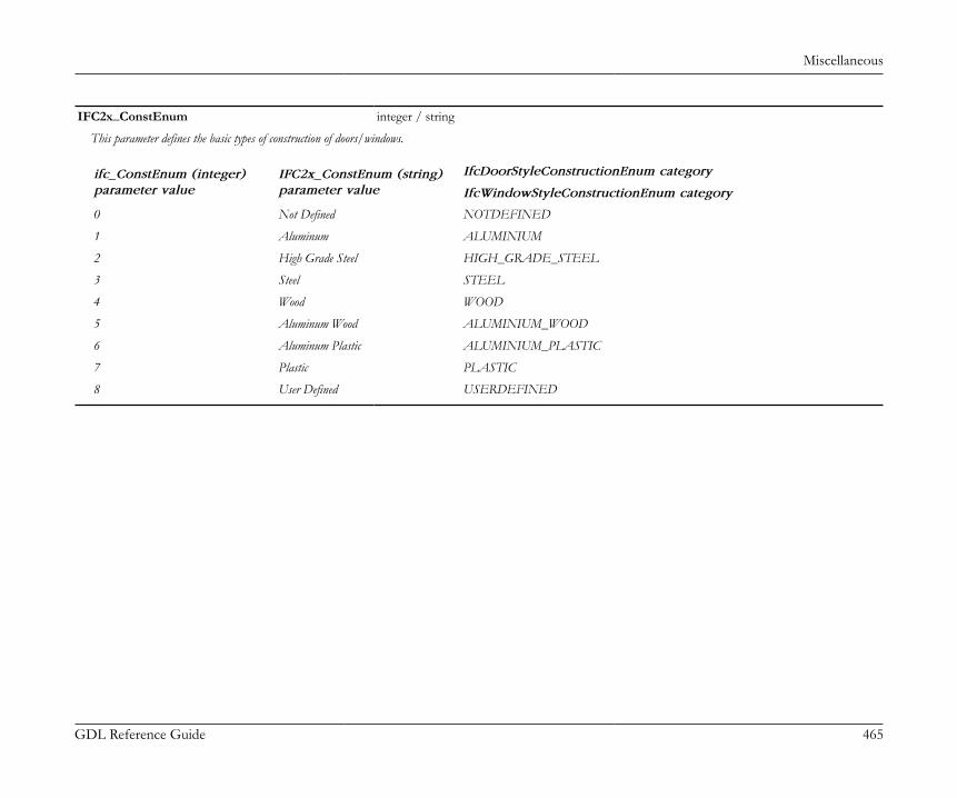
Miscellaneous
GDL Reference Guide 465
IFC2x_ConstEnum integer / string
This parameter defines the basic types of construction of doors/windows.
IfcDoorStyleConstructionEnum categoryifc_ConstEnum (integer)parameter value
IFC2x_ConstEnum (string)parameter value IfcWindowStyleConstructionEnum category
0 Not Defined NOTDEFINED
1 Aluminum ALUMINIUM
2 High Grade Steel HIGH_GRADE_STEEL
3 Steel STEEL
4 Wood WOOD
5 Aluminum Wood ALUMINIUM_WOOD
6 Aluminum Plastic ALUMINIUM_PLASTIC
7 Plastic PLASTIC
8 User Defined USERDEFINED
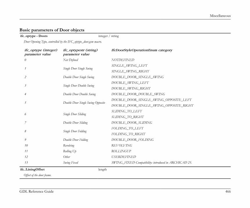
Miscellaneous
GDL Reference Guide 466
Basic parameters of Door objectsifc_optype - Doors integer / string
Door Opening Type, controlled by the IFC_optype_door.gsm macro.
ifc_optype (integer)parameter value
ifc_optypestr (string)parameter value
IfcDoorStyleOperationEnum category
0 Not Defined NOTDEFINED
SINGLE_SWING_LEFT1 Single Door Single Swing
SINGLE_SWING_RIGHT
2 Double Door Single Swing DOUBLE_DOOR_SINGLE_SWING
DOUBLE_SWING_LEFT3 Single Door Double Swing
DOUBLE_SWING_RIGHT
4 Double Door Double Swing DOUBLE_DOOR_DOUBLE_SWING
DOUBLE_DOOR_SINGLE_SWING_OPPOSITE_LEFT5 Double Door Single Swing Opposite
DOUBLE_DOOR_SINGLE_SWING_OPPOSITE_RIGHT
SLIDING_TO_LEFT6 Single Door Sliding
SLIDING_TO_RIGHT
7 Double Door Sliding DOUBLE_DOOR_SLIDING
FOLDING_TO_LEFT8 Single Door Folding
FOLDING_TO_RIGHT
9 Double Door Folding DOUBLE_DOOR_FOLDING
10 Revolving REVOLVING
11 Rolling Up ROLLINGUP
12 Other USERDEFINED
13 Swing Fixed SWING_FIXED Compatibility: introduced in ARCHICAD 23.
ifc_LiningOffset length
Offset of the door frame.
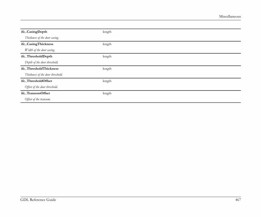
Miscellaneous
GDL Reference Guide 467
ifc_CasingDepth length
Thickness of the door casing.
ifc_CasingThickness length
Width of the door casing.
ifc_ThresholdDepth length
Depth of the door threshold.
ifc_ThresholdThickness length
Thickness of the door threshold.
ifc_ThresholdOffset length
Offset of the door threshold.
ifc_TransomOffset length
Offset of the transom.
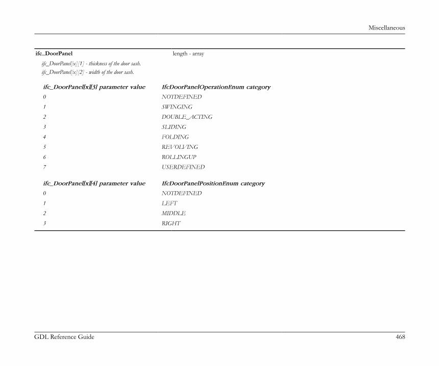
Miscellaneous
GDL Reference Guide 468
ifc_DoorPanel length - array
ifc_DoorPanel[x][1] - thickness of the door sash.ifc_DoorPanel[x][2] - width of the door sash.
ifc_DoorPanel[x][3] parameter value IfcDoorPanelOperationEnum category
0 NOTDEFINED
1 SWINGING
2 DOUBLE_ACTING
3 SLIDING
4 FOLDING
5 REVOLVING
6 ROLLINGUP
7 USERDEFINED
ifc_DoorPanel[x][4] parameter value IfcDoorPanelPositionEnum category
0 NOTDEFINED
1 LEFT
2 MIDDLE
3 RIGHT
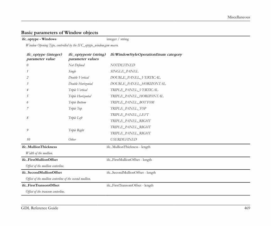
Miscellaneous
GDL Reference Guide 469
Basic parameters of Window objectsifc_optype - Windows integer / string
Window Opening Type, controlled by the IFC_optype_window.gsm macro.
ifc_optype (integer)parameter value
ifc_optypestr (string)parameter values
IfcWindowStyleOperationEnum category
0 Not Defined NOTDEFINED
1 Single SINGLE_PANEL
2 Double Vertical DOUBLE_PANEL_VERTICAL
3 Double Horizontal DOUBLE_PANEL_HORIZONTAL
4 Triple Vertical TRIPLE_PANEL_VERTICAL
5 Triple Horizontal TRIPLE_PANEL_HORIZONTAL
6 Triple Bottom TRIPLE_PANEL_BOTTOM
7 Triple Top TRIPLE_PANEL_TOP
TRIPLE_PANEL_LEFT8 Triple Left
TRIPLE_PANEL_RIGHT
TRIPLE_PANEL_RIGHT9 Triple Right
TRIPLE_PANEL_RIGHT
10 Other USERDEFINED
ifc_MullionThickness ifc_MullionThickness - length
Width of the mullion.
ifc_FirstMullionOffset ifc_FirstMullionOffset - length
Offset of the mullion centerline.
ifc_SecondMullionOffset ifc_SecondMullionOffset - length
Offset of the mullion centerline of the second mullion.
ifc_FirstTransomOffset ifc_FirstTransomOffset - length
Offset of the transom centerline.

Miscellaneous
GDL Reference Guide 470
ifc_SecondTransomOffset ifc_SecondTransomOffset - length
Offset of the transom centerline for the second mullion.

Miscellaneous
GDL Reference Guide 471
ifc_WindowPanel length - array
ifc_WindowPanel[x][1] - thickness of the window sash.ifc_WindowPanel[x][2] - width of the window sash.
ifc_WindowPanel[x][3] parameter value IfcWindowPanelOperationEnum category
0 NOTDEFINED
1 SIDEHUNGRIGHTHAND
2 SIDEHUNGLEFTHAND
3 TILTANDTURNRIGHTHAND
4 TILTANDTURNLEFTHAND
5 TOPHUNG
6 BOTTOMHUNG
7 PIVOTHORIZONTAL
8 PIVOTVERTICAL
9 SLIDINGHORIZONTAL
10 SLIDINGVERTICAL
11 REMOVABLECASEMENT
12 FIXEDCASEMENT
13 OTHEROPERATION
ifc_WindowPanel[x][4] parameter value IfcWindowPanelPositionEnum category
0 NOTDEFINED
1 LEFT
2 MIDDLE
3 RIGHT
4 BOTTOM
5 TOP
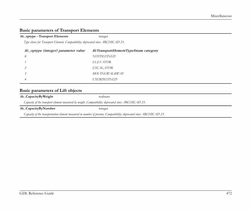
Miscellaneous
GDL Reference Guide 472
Basic parameters of Transport Elementsifc_optype - Transport Elements integer
Type choice for Transport Element. Compatibility: deprecated since ARCHICAD 23.
ifc_optype (integer) parameter value IfcTransportElementTypeEnum category
0 NOTDEFINED
1 ELEVATOR
2 ESCALATOR
3 MOVINGWALKWAY
4 USERDEFINED
Basic parameters of Lift objectsifc_CapacityByWeight realnum
Capacity of the transport element measured by weight. Compatibility: deprecated since ARCHICAD 23.
ifc_CapacityByNumber integer
Capacity of the transportation element measured in number of persons. Compatibility: deprecated since ARCHICAD 23.

Miscellaneous
GDL Reference Guide 473
Basic parameters of Stair objectsifc_StairType integer
The basic configuration of the stair type in terms of the number of stair flights and the number of landings, controlled by the StairMaker add-on for the built-in stairs.
0 Not Defined
1 StraightRunStair
2 TwoStraightRunStair
3 QuarterWindingStair
4 QuarterTurnStair
5 HalfWindingStair
6 HalfTurnStair
7 TwoQuarterWindingStair
8 TwoQuarterTurnStair
9 ThreeQuarterWindingStair
10 ThreeQuarterTurnStair
11 SpiralStair
12 DoubleReturnStair
13 CurvedRunStair
14 TwoCurvedRunStair
15 OtherOperation
ifc_NumberOfRiser integer
Total number of risers in the stair.
ifc_NumberOfTreads integer
Total number of treads in the stair.
ifc_RiserHeight length
Vertical distance from tread to tread. The riser height is supposed to be equal for all steps of a stair or stair flight.
Miscellaneous
GDL Reference Guide 474
ifc_TreadLength length
Horizontal distance from the front of the tread to the front of the next tread. The tread length is supposed to be equal for all steps of the stair or stair flight at the walking line.
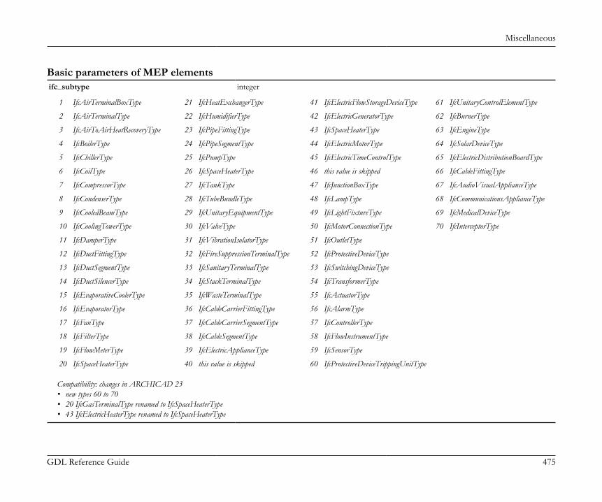
Miscellaneous
GDL Reference Guide 475
Basic parameters of MEP elementsifc_subtype integer
1 IfcAirTerminalBoxType 21 IfcHeatExchangerType 41 IfcElectricFlowStorageDeviceType 61 IfcUnitaryControlElementType
2 IfcAirTerminalType 22 IfcHumidifierType 42 IfcElectricGeneratorType 62 IfcBurnerType
3 IfcAirToAirHeatRecoveryType 23 IfcPipeFittingType 43 IfcSpaceHeaterType 63 IfcEngineType
4 IfcBoilerType 24 IfcPipeSegmentType 44 IfcElectricMotorType 64 IfcSolarDeviceType
5 IfcChillerType 25 IfcPumpType 45 IfcElectricTimeControlType 65 IfcElectricDistributionBoardType
6 IfcCoilType 26 IfcSpaceHeaterType 46 this value is skipped 66 IfcCableFittingType
7 IfcCompressorType 27 IfcTankType 47 IfcJunctionBoxType 67 IfcAudioVisualApplianceType
8 IfcCondenserType 28 IfcTubeBundleType 48 IfcLampType 68 IfcCommunicationsApplianceType
9 IfcCooledBeamType 29 IfcUnitaryEquipmentType 49 IfcLightFixtureType 69 IfcMedicalDeviceType
10 IfcCoolingTowerType 30 IfcValveType 50 IfcMotorConnectionType 70 IfcInterceptorType
11 IfcDamperType 31 IfcVibrationIsolatorType 51 IfcOutletType
12 IfcDuctFittingType 32 IfcFireSuppressionTerminalType 52 IfcProtectiveDeviceType
13 IfcDuctSegmentType 33 IfcSanitaryTerminalType 53 IfcSwitchingDeviceType
14 IfcDuctSilencerType 34 IfcStackTerminalType 54 IfcTransformerType
15 IfcEvaporativeCoolerType 35 IfcWasteTerminalType 55 IfcActuatorType
16 IfcEvaporatorType 36 IfcCableCarrierFittingType 56 IfcAlarmType
17 IfcFanType 37 IfcCableCarrierSegmentType 57 IfcControllerType
18 IfcFilterType 38 IfcCableSegmentType 58 IfcFlowInstrumentType
19 IfcFlowMeterType 39 IfcElectricApplianceType 59 IfcSensorType
20 IfcSpaceHeaterType 40 this value is skipped 60 IfcProtectiveDeviceTrippingUnitType
Compatibility: changes in ARCHICAD 23• new types 60 to 70• 20 IfcGasTerminalType renamed to IfcSpaceHeaterType• 43 IfcElectricHeaterType renamed to IfcSpaceHeaterType

Miscellaneous
GDL Reference Guide 476
Parameters for Text HandlingBefore ARCHICAD 22, selected Text Style controls were available for annotation tools (therefore library parts) spread on various settingsdialog panels. Starting from ARCHICAD 22, a standard set of text handling controls became part of every annotation dialog in form of adedicated "Text Style" panel.Library parts belonging to such tools have access to these functions by using the following fix named optional parameters.Starting from ARCHICAD 22, the locking/hiding of the corresponding ARCHICAD interface controls (if exist) is an option by using LOCKand HIDEPARAMETER commands via the parameter script of the library part, combined with "Enable hide/lock of specific fix named optionalparameters" setting (see "Details/Compatibility Options" dialog of the object in the Library Part Editor).For tool/version history, refer to the compatibility notes of each parameter.By default, the following parameters are considered available and compatible before ARCHICAD 22, while exceptions are mentioned separately.
AC_TextFont_1 string
Name of the currently selected/stored Font Type.Compatibility: introduced in ARCHICAD 22 for Label objects. The similar global variable "LABEL_FONT_NAME" is considered deprecated since.
AC_TextSize_1 real
Currently set/stored Font Size value in mm.Compatibility: introduced in ARCHICAD 22 for Label and Zone objects. The similar global variable "LABEL_TEXT_SIZE" is considered deprecated in Labels. In Zoneobjects, the "ROOM_LSIZE" fix named optional parameter is also considered deprecated since.
AC_TextStyle_1 integer
Font Style value mask. Can be used as direct input parameter for DEFINE STYLE{2} or UI_TEXTSTYLE_INFIELD.values:
values = j1 + 2*j2 + 4*j3 + 128*j8, where each j can be 0 or 1.j1: bold,j2: italic,j3: underline,j8: strikethrough.If AC_TextStyle_1 = 0, then style is normal.
Compatibility: introduced in ARCHICAD 22 for Zone and Label objects. The similar global variable "LABEL_FONT_STYLE2" is considered deprecated in Labels.

Miscellaneous
GDL Reference Guide 477
AC_TextPen_1 integer
Index of the currently selected/stored Text Pen.Compatibility: introduced in ARCHICAD 22 for Zone and Label objects. The similar global variable "LABEL_TEXT_PEN" is considered deprecated since in Labels.
The following set of text handling parameters are available for all annotation-type library parts. In Labels, the corresponding global variablesare considered deprecated. See the section called “Deprecated Label Global Variables” for the full list of out-of-date label globals.
AC_TextAlignment_1 integer
Alignment of the text.1 - left aligned, 2 - center aligned, 3 - right aligned, 4 - full justifiedCompatibility: introduced in ARCHICAD 22. In Labels, the similar global variable "LABEL_TEXT_ALIGN" is considered deprecated since ARCHICAD 22.
AC_TextLeading_1 real
Line spacing factor of the text.Compatibility: introduced in ARCHICAD 22. In Labels, the similar global variable "LABEL_TEXT_LEADING" is considered deprecated since ARCHICAD 22.
AC_TextCharWidthFactor_1 real
Character width factor of the text.Compatibility: introduced in ARCHICAD 22. In Labels, the similar global variable "LABEL_TEXT_WIDTH_FACT" is considered deprecated since ARCHICAD 22.
AC_TextCharSpaceFactor_1 real
Character spacing factor of the text.Compatibility: introduced in ARCHICAD 22. In Labels, the similar global variable "LABEL_TEXT_CHARSPACE_FACT" is considered deprecated since ARCHICAD22.
Parameters for Labels
Parameters set or read by ARCHICADThe following set of label parameters were all introduced in ARCHICAD 22, so the parallel global variables are considered deprecated. See thesection called “Deprecated Label Global Variables” for the full list of out-of-date label globals.Starting from ARCHICAD 22, the locking/hiding of the corresponding ARCHICAD interface controls (if exist) is an option by using LOCKand HIDEPARAMETER commands via the parameter script of the library part, combined with "Enable hide/lock of specific fix named optionalparameters" setting (see "Details/Compatibility Options" dialog of the object in the Library Part Editor).

Miscellaneous
GDL Reference Guide 478
AC_bLabelAlwaysReadable Boolean
1 - "Always Readable" is checked on "Label Settings/Text Style" panel, 0 otherwiseCompatibility: introduced in ARCHICAD 22. The similar global variable "LABEL_ALWAYS_READABLE" is considered deprecated since ARCHICAD 22.
AC_bLabelTextWrap Boolean
1 - "Wrap Text" is checked on "Label Settings/Text Style" panel, 0 otherwiseCompatibility: introduced in ARCHICAD 22. The similar global variable "LABEL_TEXT_WRAP" is considered deprecated since ARCHICAD 22.
AC_bLabelOpaqueFill Boolean
1 - "Opaque" is checked on "Label Settings/Text Style" panel, 0 otherwiseCompatibility: introduced in ARCHICAD 22. The similar global variable "LABEL_TEXT_BG_PEN" is considered deprecated since ARCHICAD 22.
AC_LabelTextBgrPen integer
Contains the index of the selected Text Fill Pen.Compatibility: introduced in ARCHICAD 22. The similar global variable "LABEL_TEXT_BG_PEN" is considered deprecated since ARCHICAD 22.
AC_bLabelFrame Boolean
1 - "Frame" is checked, 0 - "Frame" is unchecked.Compatibility: introduced in ARCHICAD 22. The similar global variable "LABEL_FRAME_ON" is considered deprecated since ARCHICAD 22.
AC_LabelFrameOffset length
Frame offset value according to "Label Settings/Text Style" panel.Compatibility: introduced in ARCHICAD 22. The similar global variable "LABEL_FRAME_OFFSET" is considered deprecated since ARCHICAD 22.
AC_LabelPointerPen pen
Contains the index of the selected Pointer Line Pen.Compatibility: introduced in ARCHICAD 22. The similar global variable "LABEL_ARROW_PEN" is considered deprecated since ARCHICAD 22.
AC_LabelPointerLineType line type
Contains the index of the selected Pointer Line Type.Compatibility: introduced in ARCHICAD 22. The similar global variable "LABEL_ARROW_LINETYPE" is considered deprecated since ARCHICAD 22.
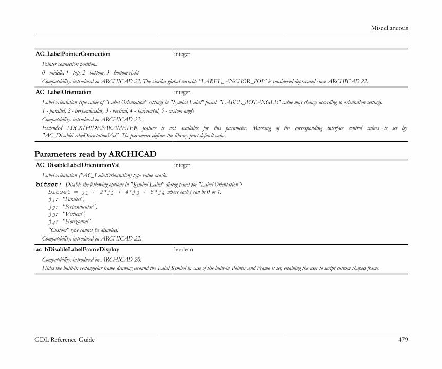
Miscellaneous
GDL Reference Guide 479
AC_LabelPointerConnection integer
Pointer connection position.0 - middle, 1 - top, 2 - bottom, 3 - bottom rightCompatibility: introduced in ARCHICAD 22. The similar global variable "LABEL_ANCHOR_POS" is considered deprecated since ARCHICAD 22.
AC_LabelOrientation integer
Label orientation type value of "Label Orientation" settings in "Symbol Label" panel. "LABEL_ROTANGLE" value may change according to orientation settings.1 - parallel, 2 - perpendicular, 3 - vertical, 4 - horizontal, 5 - custom angleCompatibility: introduced in ARCHICAD 22.Extended LOCK/HIDEPARAMETER feature is not available for this parameter. Masking of the corresponding interface control values is set by"AC_DisableLabelOrientationVal". The parameter defines the library part default value.
Parameters read by ARCHICADAC_DisableLabelOrientationVal integer
Label orientation ("AC_LabelOrientation) type value mask.bitset: Disable the following options in "Symbol Label" dialog panel for "Label Orientation":
bitset = j1 + 2*j2 + 4*j3 + 8*j4, where each j can be 0 or 1.j1: "Parallel",j2: "Perpendicular",j3: "Vertical",j4: "Horizontal"."Custom" type cannot be disabled.
Compatibility: introduced in ARCHICAD 22.
ac_bDisableLabelFrameDisplay boolean
Compatibility: introduced in ARCHICAD 20.Hides the built-in rectangular frame drawing around the Label Symbol in case of the built-in Pointer and Frame is set, enabling the user to script custom shaped frame.

Miscellaneous
GDL Reference Guide 480
ac_bCustomPointerConnection boolean
Compatibility: introduced in ARCHICAD 20.Controls the automatic Pointer Connections of the Label Symbol in case of the built-in Pointer is set. If this parameter is set to ON, 6 hotspots can be defined in the 2D script for thecustom pointer connection in accordance with the built-in types. These hotspots should have fix ID-s from 1 to 6. The ID's indicate the following connection positions:If the Pointer is on the left side of the Label Symbol:• 1: left top connection• 3: left middle connection• 5: left bottom connection• 6: right bottom connectionIf the Pointer is on the right side of the Label Symbol:• 2: right top connection• 4: right middle connection• 6: right bottom connection• 5: left bottom connection
Deprecated parameters
Deprecated Beam/Column parameters - available for listing and labels onlyFrom ARCHICAD 23 these values are available in BEAM_SEGMENT_INFO and COLU_SEGMENT_INFO global variables withuniformized value references. See also the section called “Deprecated Beam/Column Global Variables - available for listing and labelsonly”. For compatibility, they are still available on homogeneous, straight or horizontally curved Beams and on homogeneous Columns(GLOB_ELEM_TYPE = 12 or 6).
ac_colu_crosssection_type cross-section type of the column (integer)
Column Segment (27) Single-segment Column (6) Multi-segment Column (6)
1 - rectangular, 2 - round, 3 - complex profiled
ac_beam_crosssection_type cross-section type of the beam (integer)
Beam Segment (28) Single-segment Beam (12) Multi-segment Beam (12)
1 - rectangular, 2 - complex profiled
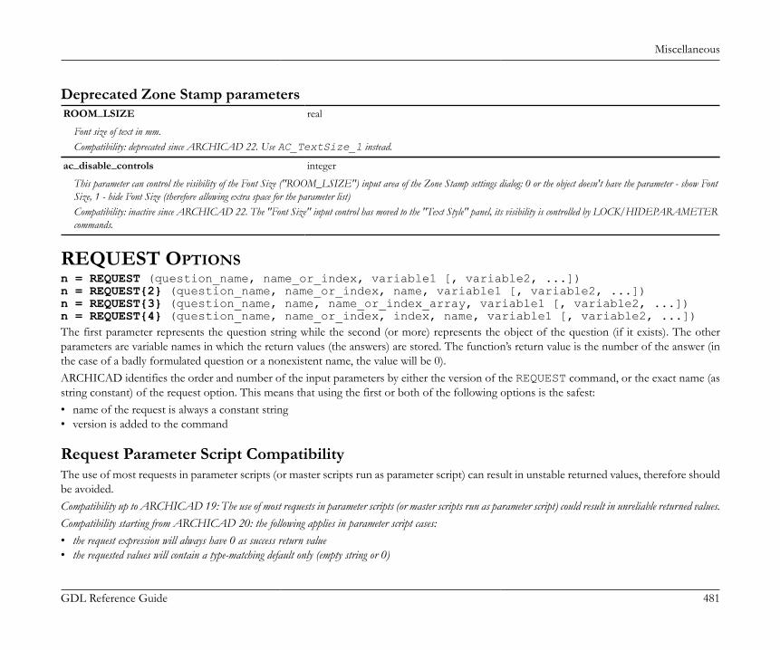
Miscellaneous
GDL Reference Guide 481
Deprecated Zone Stamp parametersROOM_LSIZE real
Font size of text in mm.Compatibility: deprecated since ARCHICAD 22. Use AC_TextSize_1 instead.
ac_disable_controls integer
This parameter can control the visibility of the Font Size ("ROOM_LSIZE") input area of the Zone Stamp settings dialog: 0 or the object doesn't have the parameter - show FontSize, 1 - hide Font Size (therefore allowing extra space for the parameter list)Compatibility: inactive since ARCHICAD 22. The "Font Size" input control has moved to the "Text Style" panel, its visibility is controlled by LOCK/HIDEPARAMETERcommands.
REQUEST OPTIONSn = REQUEST (question_name, name_or_index, variable1 [, variable2, ...])n = REQUEST{2} (question_name, name_or_index, name, variable1 [, variable2, ...])n = REQUEST{3} (question_name, name, name_or_index_array, variable1 [, variable2, ...])n = REQUEST{4} (question_name, name_or_index, index, name, variable1 [, variable2, ...])The first parameter represents the question string while the second (or more) represents the object of the question (if it exists). The otherparameters are variable names in which the return values (the answers) are stored. The function’s return value is the number of the answer (inthe case of a badly formulated question or a nonexistent name, the value will be 0).ARCHICAD identifies the order and number of the input parameters by either the version of the REQUEST command, or the exact name (asstring constant) of the request option. This means that using the first or both of the following options is the safest:• name of the request is always a constant string• version is added to the command
Request Parameter Script CompatibilityThe use of most requests in parameter scripts (or master scripts run as parameter script) can result in unstable returned values, therefore shouldbe avoided.Compatibility up to ARCHICAD 19: The use of most requests in parameter scripts (or master scripts run as parameter script) could result in unreliable returned values.Compatibility starting from ARCHICAD 20: the following applies in parameter script cases:• the request expression will always have 0 as success return value• the requested values will contain a type-matching default only (empty string or 0)

Miscellaneous
GDL Reference Guide 482
Using restricted requests in the parameter script will also generate GDL warnings starting from ARCHICAD 19.To check the parameter script compatibility, refer to the tables below.:Legend:
works without restriction
works (with additional warning)
does not work: expression returns 0, while containing dummy type-matching defaults in returned variables (empty string or 0) - withadditional warning
Compatibility in Parameter Script ARCHICAD 18 ARCHICAD 19 ARCHICAD 20
ANCESTRY_INFO
ANGULAR_DIMENSION
ANGULAR_LENGTH_DIMENSION
AREA_DIMENSION
ASSOCEL_PROPERTIES
ASSOCLP_NAME
ASSOCLP_PARVALUE
ASSOCLP_PARVALUE_WITH_DESCRIPTION
AUTOTEXT_LIST - -
Compatibility in Parameter Script ARCHICAD 18 ARCHICAD 19 ARCHICAD 20
BUILDING_MATERIAL_INFO
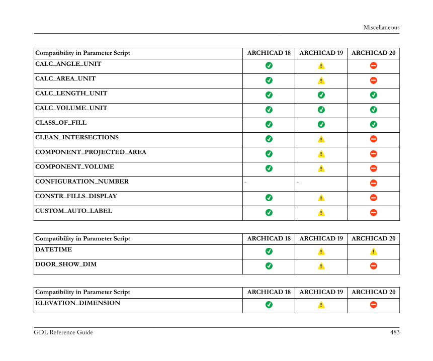
Miscellaneous
GDL Reference Guide 483
Compatibility in Parameter Script ARCHICAD 18 ARCHICAD 19 ARCHICAD 20
CALC_ANGLE_UNIT
CALC_AREA_UNIT
CALC_LENGTH_UNIT
CALC_VOLUME_UNIT
CLASS_OF_FILL
CLEAN_INTERSECTIONS
COMPONENT_PROJECTED_AREA
COMPONENT_VOLUME
CONFIGURATION_NUMBER - -
CONSTR_FILLS_DISPLAY
CUSTOM_AUTO_LABEL
Compatibility in Parameter Script ARCHICAD 18 ARCHICAD 19 ARCHICAD 20
DATETIME
DOOR_SHOW_DIM
Compatibility in Parameter Script ARCHICAD 18 ARCHICAD 19 ARCHICAD 20
ELEVATION_DIMENSION

Miscellaneous
GDL Reference Guide 484
Compatibility in Parameter Script ARCHICAD 18 ARCHICAD 19 ARCHICAD 20
FLOOR_PLAN_OPTION
FONTNAMES_LIST
FULL_ID_OF_PARENT -
Compatibility in Parameter Script ARCHICAD 18 ARCHICAD 19 ARCHICAD 20
HEIGHT_OF_STYLE
HOME_STORY
HOME_STORY_OF_OPENING
HOMEDB_INFO
Compatibility in Parameter Script ARCHICAD 18 ARCHICAD 19 ARCHICAD 20
ID_OF_MAIN
INTERNAL_ID
Compatibility in Parameter Script ARCHICAD 18 ARCHICAD 19 ARCHICAD 20
LAYOUT_LENGTH_UNIT
LAYOUT_TEXT_SIZE_UNIT
LEVEL_DIMENSION
LINEAR_DIMENSION

Miscellaneous
GDL Reference Guide 485
Compatibility in Parameter Script ARCHICAD 18 ARCHICAD 19 ARCHICAD 20
MATCHING_PROPERTIES
MATERIAL_INFO
MODEL_LENGTH_UNIT
MODEL_TEXT_SIZE_UNIT
Compatibility in Parameter Script ARCHICAD 18 ARCHICAD 19 ARCHICAD 20
NAME_OF_FILL
NAME_OF_LINE_TYPE
NAME_OF_LISTED
NAME_OF_MACRO
NAME_OF_MAIN
NAME_OF_MATERIAL
NAME_OF_PLAN
NAME_OF_PROGRAM
NAME_OF_STYLE
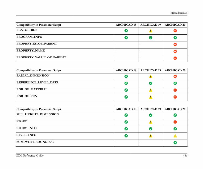
Miscellaneous
GDL Reference Guide 486
Compatibility in Parameter Script ARCHICAD 18 ARCHICAD 19 ARCHICAD 20
PEN_OF_RGB
PROGRAM_INFO
PROPERTIES_OF_PARENT - -
PROPERTY_NAME - -
PROPERTY_VALUE_OF_PARENT - -
Compatibility in Parameter Script ARCHICAD 18 ARCHICAD 19 ARCHICAD 20
RADIAL_DIMENSION
REFERENCE_LEVEL_DATA
RGB_OF_MATERIAL
RGB_OF_PEN
Compatibility in Parameter Script ARCHICAD 18 ARCHICAD 19 ARCHICAD 20
SILL_HEIGHT_DIMENSION
STORY
STORY_INFO
STYLE_INFO
SUM_WITH_ROUNDING - -
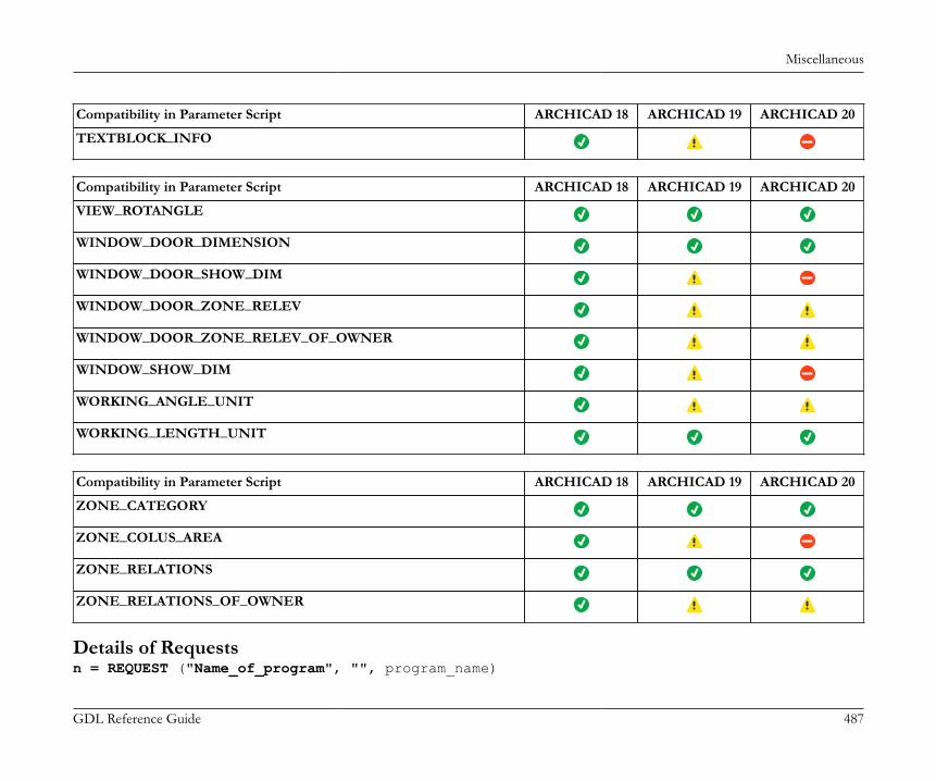
Miscellaneous
GDL Reference Guide 487
Compatibility in Parameter Script ARCHICAD 18 ARCHICAD 19 ARCHICAD 20
TEXTBLOCK_INFO
Compatibility in Parameter Script ARCHICAD 18 ARCHICAD 19 ARCHICAD 20
VIEW_ROTANGLE
WINDOW_DOOR_DIMENSION
WINDOW_DOOR_SHOW_DIM
WINDOW_DOOR_ZONE_RELEV
WINDOW_DOOR_ZONE_RELEV_OF_OWNER
WINDOW_SHOW_DIM
WORKING_ANGLE_UNIT
WORKING_LENGTH_UNIT
Compatibility in Parameter Script ARCHICAD 18 ARCHICAD 19 ARCHICAD 20
ZONE_CATEGORY
ZONE_COLUS_AREA
ZONE_RELATIONS
ZONE_RELATIONS_OF_OWNER
Details of Requestsn = REQUEST ("Name_of_program", "", program_name)
Miscellaneous
GDL Reference Guide 488
Returns in the given variable the name of the program, e.g., "ARCHICAD". Expression returns 0 and contains dummy return values (emtpy string or0) if used in parameter script, causing additional warning.
Example 1: Printing the name of the programn = REQUEST ("Name_of_program", "", program_name)PRINT program_name
n = REQUEST ("Name_of_macro", "", my_name)n = REQUEST ("Name_of_main", "", main_name)After executing these function calls, the my_name variable will contain the name of the macro, while main_name will contain the name of themain macro (if it doesn’t exist, empty string).n = REQUEST ("ID_of_main", "", id_string)For library parts placed on the floor plan, returns the identifier set in the tool’s settings dialog box in the id_string variable (otherwise emptystring). Not working on annotation elements (e.g. Label, D/W Marker, Zone Stamp). Expression returns 0 and contains dummy return values (emtpystring or 0) if used in parameter script, causing additional warning.n = REQUEST ("Full_ID_of_parent", "", id_string)For annotation elements linked or hotlinked on the floor plan, returns all identifiers (Master ID) of the linked modules and the parent libraryparts’ identifier set in the tool’s settings dialog box in the id_string variable (otherwise empty string). Expression returns 0 and contains dummy returnvalues (emtpy string or 0) if used in parameter script, causing additional warning.n = REQUEST ("Name_of_plan", "", name)Returns in the given variable the name of the current project. Expression returns 0 and contains dummy return values (emtpy string or 0) if used in parameterscript, causing additional warning.n = REQUEST ("Story", "", index, story_name)Returns in the index and story_name variables the index and the name of the current story. Expression returns 0 and contains dummy return values(emtpy string or 0) if used in parameter script, causing additional warning.n = REQUEST ("Home_story", "", index, story_name)Returns in the index and story_name variables the index and the name of the home story.n = REQUEST ("Home_story_of_opening", "", index, story_name)Returns the index and the name of the home story of the opening in the index and story_name variables. The home story is the first story,where the opening is visible. Can be used in scripts of doors, windows, wallends, corner windows and skylights, and in the script of their labelsand markers. Causes warning if used in parameter script.
Miscellaneous
GDL Reference Guide 489
n = REQUEST ("Story_info", expr, nStories, index1, name1, elev1, height1 [, index2, name2, ...])Returns the story information in the given variables: number of stories and story index, name, elevation, height to next successively. If expr is anumerical expression, it means a story index: only the number of stories and the information on the specified story is returned. If expr is a stringexpression, it means that information on all stories is requested. The return value of the function is the number of successfully retrieved values.
Example 2:DIM t[]n = REQUEST ("STORY_INFO", "", nr, t)FOR i = 1 TO nr nr = STR ("%.0m", t [4 * (i - 1) + 1]) name = t [4 * (i - 1) + 2] elevation = STR ("%m", t [4 * (i - 1) + 3]) height = STR ("%m", t [4 * (i - 1) + 4]) TEXT2 0, -i, nr + "," + name + "," + elevation + "," + heightNEXT i
With the following requests, you can learn the dimension formats set in the Options/Project Preferences/Dimensions and Calculation Units& Rules dialog boxes. These requests return a format string that can be used as the first parameter in the STR () function.n = REQUEST ("Linear_dimension", "", format_string)n = REQUEST ("Angular_dimension", "", format_string)Expression returns 0 and contains dummy return values (emtpy string or 0) if used in parameter script, causing additional warning.n = REQUEST ("Angular_length_dimension", "", format_string)Expression returns 0 and contains dummy return values (emtpy string or 0) if used in parameter script, causing additional warning.n = REQUEST ("Radial_dimension", "", format_string)Causes warning if used in parameter script.n = REQUEST ("Level_dimension", "", format_string)Causes warning if used in parameter script.n = REQUEST ("Elevation_dimension", "", format_string)Expression returns 0 and contains dummy return values (emtpy string or 0) if used in parameter script, causing additional warning.n = REQUEST ("Window_door_dimension", "", format_string)n = REQUEST ("Sill_height_dimension", "", format_string)

Miscellaneous
GDL Reference Guide 490
n = REQUEST ("Area_dimension", "", format_string)n = REQUEST ("Calc_length_unit", "", format_string)n = REQUEST ("Calc_area_unit", "", format_string)Expression returns 0 and contains dummy return values (emtpy string or 0) if used in parameter script, causing additional warning.n = REQUEST ("Calc_volume_unit", "", format_string)n = REQUEST ("Calc_angle_unit", "", format_string)Expression returns 0 and contains dummy return values (emtpy string or 0) if used in parameter script, causing additional warning.
Example 3:format = "" num = 60.55n = REQUEST ("Angular_dimension", "",format)!"%.2dd"TEXT2 0, 0, STR (format, num)!60.55
n = REQUEST ("Clean_intersections", "", state)Returns the state of the Clean Wall & Beam Intersections feature (1 when turned on, 0 when off) Expression returns 0 and contains dummy returnvalues (emtpy string or 0) if used in parameter script, causing additional warning.n = REQUEST ("Zone_category", "", name, code)For zones, returns the name and the code string of the current zone category.n = REQUEST ("Zone_relations", "", category_name, code, name, number [, category_name2, code2, name2, number2])Returns in the given variables the zone category name and code and the name and number of the zone where the library part containing thisrequest is located. For doors and windows, there can be a maximum of two zones. The return value of the request is the number of successfullyretrieved values (0 if the library part is not inside any zone).n = REQUEST ("Zone_relations_of_owner", "", category_name, code, name, number [, category_name2, code2, name2, number2])Returns in the given variables the category name & code and the zone name & number of the zone where the owner of the object is located.So, it is meaningful, if the library part has owner (door-window labels and door-window markers, etc.). In case of a door label, its owner is thedoor. For doors and windows, there can be a maximum of two related zones. The return value of the request is the number of successfullyretrieved values (0 if the object has no owner, or its owner is not inside any zone). Causes warning if used in parameter script.n = REQUEST ("Zone_colus_area", "", area)

Miscellaneous
GDL Reference Guide 491
Returns in the area variable the total area of the columns placed in the current zone. Effective only for Zone Stamps. Available only forcompatibility reasons. It is recommended to use quantities set in Zone Stamp fix parameters. Expression returns 0 and contains dummy return values(emtpy string or 0) if used in parameter script, causing additional warning.n = REQUEST ("Custom_auto_label", "", name)Returns in the name variable the name of the custom auto label of the library part or an empty string if it does not exist. Expression returns 0 andcontains dummy return values (emtpy string or 0) if used in parameter script, causing additional warning.n = REQUEST ("Rgb_of_material", name, r, g, b)n = REQUEST ("Rgb_of_pen", penindex, r, g, b)n = REQUEST ("Pen_of_RGB", "r g b", penindex)Like the REQ() function (but in just one call), returns in the specified variables the value of the r, g, b components of the material and pen,or the index of the pen corresponding to the given RGB values. All 3 expressions return 0 containing dummy return values (emtpy string or 0) if usedin parameter script, causing additional warning.n = REQUEST ("Height_of_style", name, height [, descent, leading])Returns in the given variables the total height of the style measured in millimeters (height in meters is height / 1000 * GLOB_SCALE); thedescent (the distance in millimeters from the text base line to the descent line) and the leading (the distance in millimeters from the descentline to the ascent line).n = REQUEST ("Style_info", name, fontname [, size, anchor, face_or_slant])Returns information in the given variables on the previously defined style (see style parameters at the DEFINE STYLE command). Can be useful inmacros to collect information on the style defined in a main script. Causes warning if used in parameter script.n = REQUEST ("Name_of_material", index, name)Returns in the variable the material name identified by index. Expression returns 0 and contains dummy return values (emtpy string or 0) if used in parameterscript, causing additional warning.n = REQUEST ("Name_of_building_material", index, name)Returns in the variable the building material name identified by index. Expression returns 0 and contains dummy return values (emtpy string or 0) if usedin parameter script, causing additional warning.n = REQUEST ("Name_of_fill", index, name)Returns in the name variable the fill name identified by index. Expression returns 0 and contains dummy return values (emtpy string or 0) if used in parameterscript, causing additional warning.n = REQUEST ("Name_of_line_type", index, name)Returns in the given variable the line name identified by index. Expression returns 0 and contains dummy return values (emtpy string or 0) if used inparameter script, causing additional warning.

Miscellaneous
GDL Reference Guide 492
n = REQUEST ("Name_of_style", index, name)Returns in the given variable the name of the style identified by index. Expression returns 0 and contains dummy return values (emtpy string or 0) ifused in parameter script, causing additional warning.If index < 0, it refers to a material, fill, line type or style defined in the GDL script or the MASTER_GDL file. A call of a request with index= 0 returns in the variable the name of the default material or line type. (Empty string for fill and style.)The return value of the request is the number of successfully retrieved values (1 if no error occurred, 0 for error when the index is not valid).n = REQUEST ("WINDOW_DOOR_SHOW_DIM", "", show)Before 9.0 returns 1 in the show variable if Options/Display Options/Doors & Windows is set to "Show with Dimensions", 0 otherwise. Since9.0 display options were split to separate Door and Window display options, so for compatibility reasons ARCHICAD checks if the requestis used in a Window (or marker of a Window) or a Door (or marker of a Door) and automatically returns the corresponding display option.In other cases (symbol, lamp, label) the Window option is returned. Can be used to hide/show custom dimensions according to the currentDisplay Options. Expression returns 0 and contains dummy return values (emtpy string or 0) if used in parameter script, causing additional warning.Since 9.0 the "window_show_dim", and the "door_show_dim" separate requests are available.n = REQUEST ("window_show_dim", "", show)Returns 1 in the show variable if in the Model View Options/Window options the "with Markers" is checked, 0 otherwise. Expression returns 0and contains dummy return values (emtpy string or 0) if used in parameter script, causing additional warning.n = REQUEST ("door_show_dim", "", show)Returns 1 in the show variable if in the Model View Options/Door options the "with Markers" is checked, 0 otherwise. Expression returns 0 andcontains dummy return values (emtpy string or 0) if used in parameter script, causing additional warning.n = REQUEST ("name_of_listed", "", name)Returns in the name variable the name of the library part associated with the property type library part containing this request. For elements(Walls, Slabs, etc.), the name is an empty string. Causes warning if used in parameter script.n = REQUEST ("window_door_zone_relev", "", out_direction)Effective only for Doors and Windows. Use it as complement to the "zone_relations" request. Returns 1 in the out_direction variable if theDoor/Window opening direction is in that of the first room identified by the "zone_relations" request, 2 if the opening direction is towards thesecond room. It also returns 2 if there is only one room and the opening direction is to the outside. Causes warning if used in parameter script.n = REQUEST ("window_door_zone_relev_of_owner", "", out_direction)Effective only if the library part’s parent is a door or a window (markers, labels). Use it as a complement to the "zone_relations_of_owner"request. Returns 1 in the out_direction variable if the parent’s opening direction is in that of the first zone identified by the zone relations typerequests, 2 if the opening direction is towards the second zone. It also returns 2 if there is only one zone and the opening direction is to theoutside. Causes warning if used in parameter script.

Miscellaneous
GDL Reference Guide 493
n = REQUEST ("matching_properties", type, name1, name2, ...)If type = 1, returns in the given variables individually associated property library part names, otherwise property library part names associatedby criteria. If used in an associative label, the function returns the properties of the element the label is associated with. Expression returns 0 andcontains dummy return values (emtpy string or 0) if used in parameter script, causing additional warning.n = REQUEST ("Working_length_unit", "", format_string)n = REQUEST ("Working_angle_unit", "", format_string)With these requests, the user can get the working unit formats as set in the Options > Project Preferences > Working Units dialog box. Theyreturn a format string that can be used as the first parameter in the STR () function. The requests both work when interpreting the user interfacescript, but "Working_angle_unit" causes warning if used in parameter script.n = REQUEST ("Model_length_unit", "", format_string)n = REQUEST ("Layout_length_unit", "", format_string)With these requests, the user can get the layout and the model unit formats as set in the Options > Project Preferences > Working Units dialogbox. They return a format string that can be used as the first parameter in the STR () function. Both expressions return 0 containing dummy returnvalues (emtpy string or 0) if used in parameter script, causing additional warning. Both work in User Interface Script only.n = REQUEST ("Model_text_size_unit", "", format_string)n = REQUEST ("Layout_text_size_unit", "", format_string)With these requests, the user can get the layout and the model text size formats. They return a format string that can be used as the firstparameter in the STR () function. The requests cause warning if used in parameter script.n = REQUEST ("Properties_Of_Parent", propertyType, parentProperties)Returns the properties of the parent object. All properties are returned in one array with the following form: ID, type, group, name. Can beused only in labels. Expression returns 0 and contains dummy return values (emtpy string or 0) if used in parameter script, causing additional warning.Core property: [id, "", "", PropertyName]AC property: [guid, "", "GroupName", PropertyName]IFC property: [id, "IFC", "GroupName", PropertyName]Classification: [guid, "Classification", "", ClassificationSystemName]Profile parameter: [guid, "", "Profile Parameters", ParameterName] propertyType: keyword defining the type of the requested properties. Empty string retruns all types of properties. Possible values:"COREPROPERTY""ACPROPERTY""IFCPROPERTY""CLASSIFICATION""PROFILEPARAMETER"
Miscellaneous
GDL Reference Guide 494
Compatibility: the request is introduced in ARCHICAD 20. The property type options and the Classification property type are introduced in ARCHICAD 21,the Profile parameter property type is introduced in ARCHICAD 22.
Example 4:DIM parentProperties[]n = REQUEST ("Properties_Of_Parent", "", parentProperties)! parentProperties = [Id1, TypeName1, GroupName1, PropertyName1, Id2, TypeName2, GroupName2, PropertyName2, ... Idn, TypeNamen, GroupNamen, PropertyNamen]
n = REQUEST ("Property_Value_Of_Parent", "id", type, dim1, dim2, propertyValues)Returns value array of the selected property. Can be used only in labels. Expression returns 0 and contains dummy return values (emtpy string or 0) ifused in parameter script, causing additional warning.Compatibility: introduced in ARCHICAD 20.id: the ID of the selected property (string).type: the type of the selected property value.1: boolean2: integer3: real number4: string5: length6: area7: volume8: angle
Compatibility: length, area, volume and angle types are introduced in ARCHICAD 22.dim1, dim2: the dimensions of the propertyValues array.dim1 = 0, dim2 = 0: simple, scalar value.dim1 > 0, dim2 > 0: list of values.
Example 5:DIM propertyValues[]n = REQUEST ("Property_Value_Of_Parent", "ExampleId", type, dim1, dim2, propertyValues)
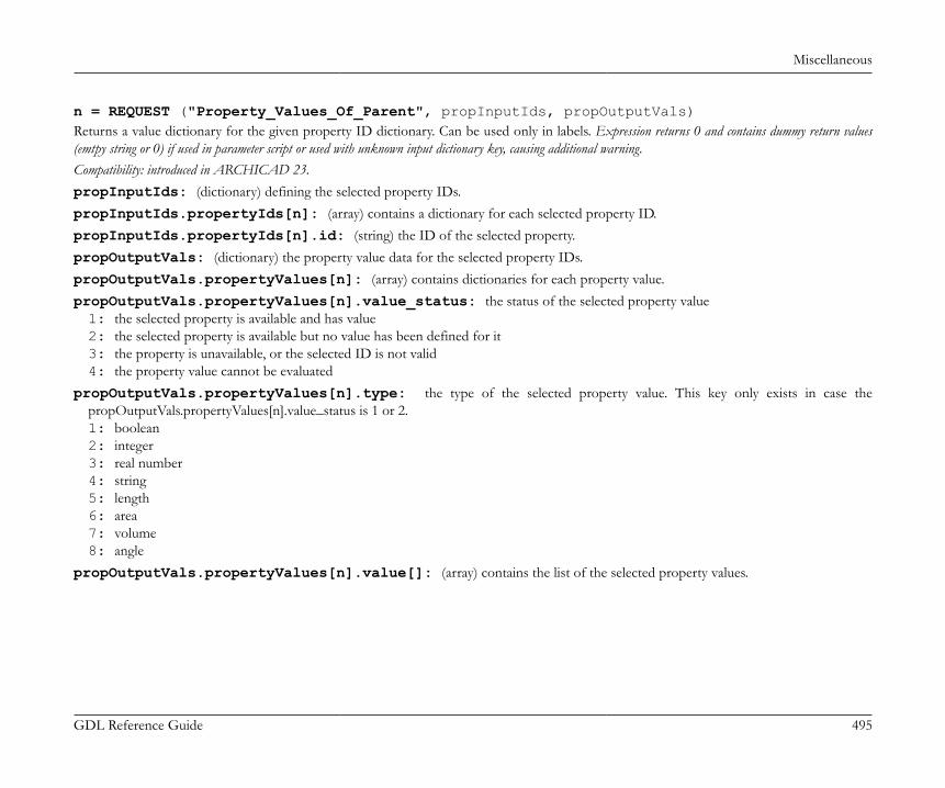
Miscellaneous
GDL Reference Guide 495
n = REQUEST ("Property_Values_Of_Parent", propInputIds, propOutputVals)Returns a value dictionary for the given property ID dictionary. Can be used only in labels. Expression returns 0 and contains dummy return values(emtpy string or 0) if used in parameter script or used with unknown input dictionary key, causing additional warning.Compatibility: introduced in ARCHICAD 23.propInputIds: (dictionary) defining the selected property IDs.propInputIds.propertyIds[n]: (array) contains a dictionary for each selected property ID.propInputIds.propertyIds[n].id: (string) the ID of the selected property.propOutputVals: (dictionary) the property value data for the selected property IDs.propOutputVals.propertyValues[n]: (array) contains dictionaries for each property value.propOutputVals.propertyValues[n].value_status: the status of the selected property value1: the selected property is available and has value2: the selected property is available but no value has been defined for it3: the property is unavailable, or the selected ID is not valid4: the property value cannot be evaluated
propOutputVals.propertyValues[n].type: the type of the selected property value. This key only exists in case thepropOutputVals.propertyValues[n].value_status is 1 or 2.1: boolean2: integer3: real number4: string5: length6: area7: volume8: angle
propOutputVals.propertyValues[n].value[]: (array) contains the list of the selected property values.

Miscellaneous
GDL Reference Guide 496
Example 6:dict propInputIds propInputIds.propertyIds[1].id = "ExampleId1" propInputIds.propertyIds[2].id = "ExampleId2" ... propInputIds.propertyIds[n].id = "ExampleIdn"dict propOutputValsn = REQUEST ("Property_Values_Of_Parent", propInputIds, propOutputVals)! propOutputVals .propertyValues[1].value_status .propertyValues[1].type .propertyValues[1].value[] .propertyValues[2].value_status .propertyValues[2].type .propertyValues[2].value[] ... .propertyValues[n].value_status .propertyValues[n].type .propertyValues[n].value[]
n = REQUEST ("Component_Properties_Of_Parent", propertyType, parentComponentProperties)Returns the component properties, which are available for at least one of the building material components of the parent object. All propertiesare returned in one array with the following form: ID, type, group, name. Can be used only in labels. Expression returns 0 and contains dummy returnvalues (emtpy string or 0) if used in parameter script, causing additional warning.AC property: [guid, "", "GroupName", PropertyName]Classification: [guid, "Classification", "", ClassificationSystemName] propertyType: keyword defining the type of the requested properties. Empty string returns all available types of properties. Possible values:"ACPROPERTY""CLASSIFICATION"
Compatibility: the request is introduced in ARCHICAD 23.

Miscellaneous
GDL Reference Guide 497
Example 7:DIM parentComponentProperties[]n = REQUEST ("Component_Properties_Of_Parent", "", parentComponentProperties)! parentComponentProperties = [Id1, TypeName1, GroupName1, PropertyName1, Id2, TypeName2, GroupName2, PropertyName2, ... Idn, TypeNamen, GroupNamen, PropertyNamen]
n = REQUEST ("Component_IDs_Of_Parent", collectComponents, outputCompIds)Returns the building material component IDs of the parent object in a dictionary form. Can be used only in labels. Expression returns 0 andcontains dummy return values (emtpy string or 0) if used in parameter script, causing additional warning.Compatibility: introduced in ARCHICAD 23.collectComponents: (dictionary) defining the method of collecting the building material components of the parent object.collectComponents.collectMode: (integer) the method of collecting the building material components. This key is optional, if it
does not exist, the request uses a default collectMode of 1.1: (default) returns all the building material component IDs of the parent2: returns the same building material component IDs in the same order as in WALL_SKINS_PARAMS, SHELLBASE_SKINS_PARAMS,SLAB_SKINS_PARAMS or ROOF_SKINS_PARAMS - depending on the element type of the parent.
outputCompIds: (dictionary) the building material component IDs of the parent object.outputCompIds.componentIds[n]: (array) contains dictionaries for each building material component ID.outputCompIds.componentIds[n].id: (integer) the building material component ID of the parent element.
Example 8:dict collectComponents collectComponents.collectMode = 1dict outputCompIdsn = REQUEST ("Component_IDs_Of_Parent", collectComponents, outputCompIds)! outputCompIds .componentIds[1].id .componentIds[2].id ... .componentIds[n].id
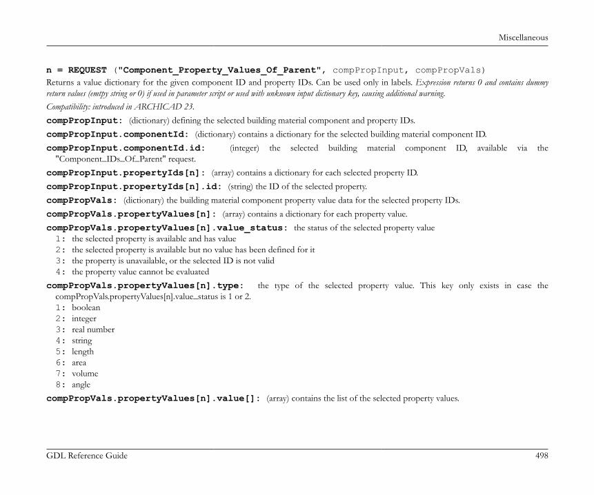
Miscellaneous
GDL Reference Guide 498
n = REQUEST ("Component_Property_Values_Of_Parent", compPropInput, compPropVals)Returns a value dictionary for the given component ID and property IDs. Can be used only in labels. Expression returns 0 and contains dummyreturn values (emtpy string or 0) if used in parameter script or used with unknown input dictionary key, causing additional warning.Compatibility: introduced in ARCHICAD 23.compPropInput: (dictionary) defining the selected building material component and property IDs.compPropInput.componentId: (dictionary) contains a dictionary for the selected building material component ID.compPropInput.componentId.id: (integer) the selected building material component ID, available via the
"Component_IDs_Of_Parent" request.compPropInput.propertyIds[n]: (array) contains a dictionary for each selected property ID.compPropInput.propertyIds[n].id: (string) the ID of the selected property.compPropVals: (dictionary) the building material component property value data for the selected property IDs.compPropVals.propertyValues[n]: (array) contains a dictionary for each property value.compPropVals.propertyValues[n].value_status: the status of the selected property value1: the selected property is available and has value2: the selected property is available but no value has been defined for it3: the property is unavailable, or the selected ID is not valid4: the property value cannot be evaluated
compPropVals.propertyValues[n].type: the type of the selected property value. This key only exists in case thecompPropVals.propertyValues[n].value_status is 1 or 2.1: boolean2: integer3: real number4: string5: length6: area7: volume8: angle
compPropVals.propertyValues[n].value[]: (array) contains the list of the selected property values.
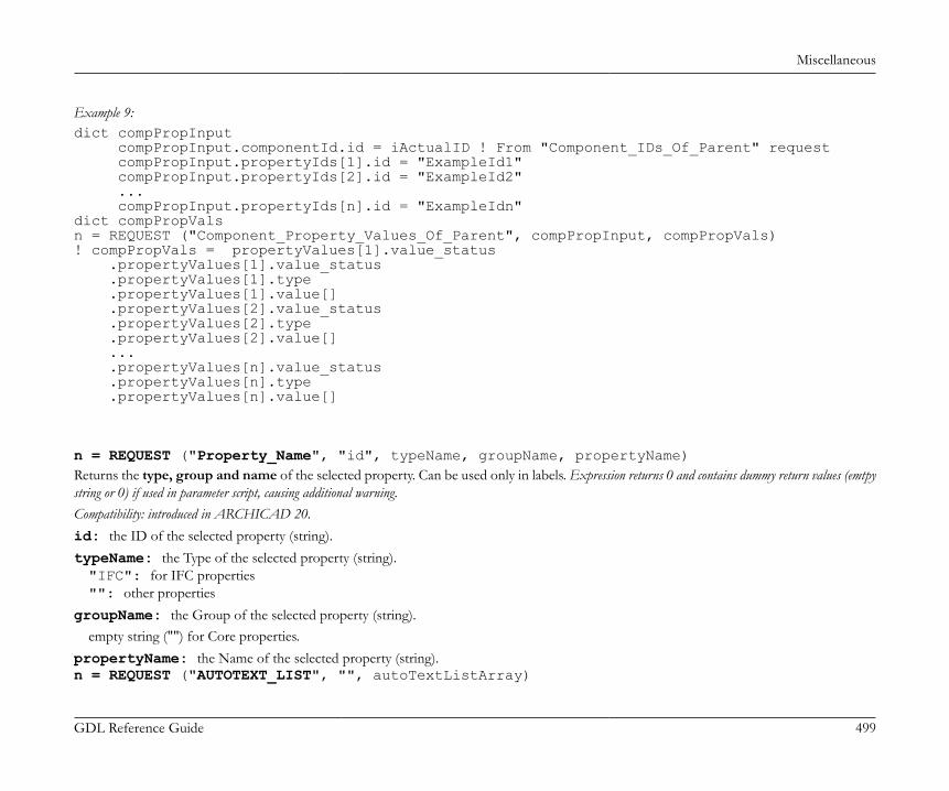
Miscellaneous
GDL Reference Guide 499
Example 9:dict compPropInput compPropInput.componentId.id = iActualID ! From "Component_IDs_Of_Parent" request compPropInput.propertyIds[1].id = "ExampleId1" compPropInput.propertyIds[2].id = "ExampleId2" ... compPropInput.propertyIds[n].id = "ExampleIdn"dict compPropValsn = REQUEST ("Component_Property_Values_Of_Parent", compPropInput, compPropVals)! compPropVals = propertyValues[1].value_status .propertyValues[1].value_status .propertyValues[1].type .propertyValues[1].value[] .propertyValues[2].value_status .propertyValues[2].type .propertyValues[2].value[] ... .propertyValues[n].value_status .propertyValues[n].type .propertyValues[n].value[]
n = REQUEST ("Property_Name", "id", typeName, groupName, propertyName)Returns the type, group and name of the selected property. Can be used only in labels. Expression returns 0 and contains dummy return values (emtpystring or 0) if used in parameter script, causing additional warning.Compatibility: introduced in ARCHICAD 20.id: the ID of the selected property (string).typeName: the Type of the selected property (string)."IFC": for IFC properties"": other properties
groupName: the Group of the selected property (string).empty string ("") for Core properties.
propertyName: the Name of the selected property (string).n = REQUEST ("AUTOTEXT_LIST", "", autoTextListArray)
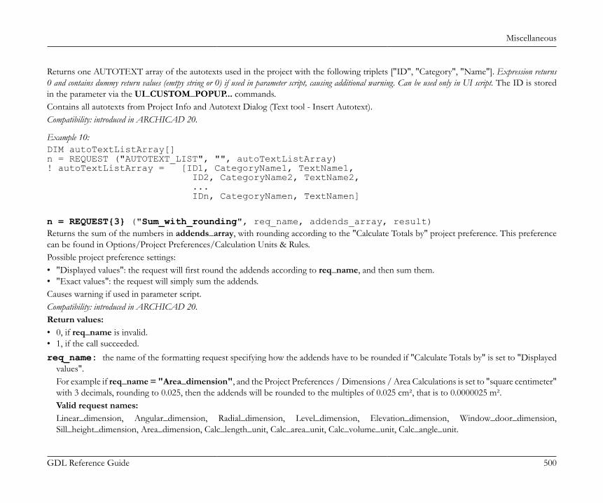
Miscellaneous
GDL Reference Guide 500
Returns one AUTOTEXT array of the autotexts used in the project with the following triplets ["ID", "Category", "Name"]. Expression returns0 and contains dummy return values (emtpy string or 0) if used in parameter script, causing additional warning. Can be used only in UI script. The ID is storedin the parameter via the UI_CUSTOM_POPUP... commands.Contains all autotexts from Project Info and Autotext Dialog (Text tool - Insert Autotext).Compatibility: introduced in ARCHICAD 20.
Example 10:DIM autoTextListArray[]n = REQUEST ("AUTOTEXT_LIST", "", autoTextListArray)! autoTextListArray = [ID1, CategoryName1, TextName1, ID2, CategoryName2, TextName2, ... IDn, CategoryNamen, TextNamen]
n = REQUEST{3} ("Sum_with_rounding", req_name, addends_array, result)Returns the sum of the numbers in addends_array, with rounding according to the "Calculate Totals by" project preference. This preferencecan be found in Options/Project Preferences/Calculation Units & Rules.Possible project preference settings:• "Displayed values": the request will first round the addends according to req_name, and then sum them.• "Exact values": the request will simply sum the addends.Causes warning if used in parameter script.Compatibility: introduced in ARCHICAD 20.Return values:• 0, if req_name is invalid.• 1, if the call succeeded.req_name: the name of the formatting request specifying how the addends have to be rounded if "Calculate Totals by" is set to "Displayed
values".For example if req_name = "Area_dimension", and the Project Preferences / Dimensions / Area Calculations is set to "square centimeter"with 3 decimals, rounding to 0.025, then the addends will be rounded to the multiples of 0.025 cm², that is to 0.0000025 m².Valid request names:Linear_dimension, Angular_dimension, Radial_dimension, Level_dimension, Elevation_dimension, Window_door_dimension,Sill_height_dimension, Area_dimension, Calc_length_unit, Calc_area_unit, Calc_volume_unit, Calc_angle_unit.
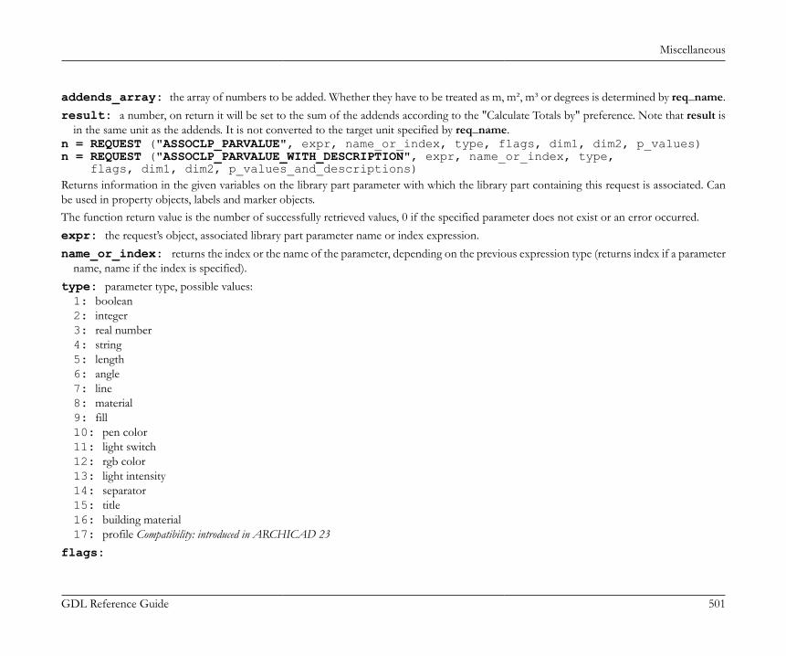
Miscellaneous
GDL Reference Guide 501
addends_array: the array of numbers to be added. Whether they have to be treated as m, m², m³ or degrees is determined by req_name.result: a number, on return it will be set to the sum of the addends according to the "Calculate Totals by" preference. Note that result is
in the same unit as the addends. It is not converted to the target unit specified by req_name.n = REQUEST ("ASSOCLP_PARVALUE", expr, name_or_index, type, flags, dim1, dim2, p_values)n = REQUEST ("ASSOCLP_PARVALUE_WITH_DESCRIPTION", expr, name_or_index, type, flags, dim1, dim2, p_values_and_descriptions)Returns information in the given variables on the library part parameter with which the library part containing this request is associated. Canbe used in property objects, labels and marker objects.The function return value is the number of successfully retrieved values, 0 if the specified parameter does not exist or an error occurred.expr: the request’s object, associated library part parameter name or index expression.name_or_index: returns the index or the name of the parameter, depending on the previous expression type (returns index if a parameter
name, name if the index is specified).type: parameter type, possible values:1: boolean2: integer3: real number4: string5: length6: angle7: line8: material9: fill10: pen color11: light switch12: rgb color13: light intensity14: separator15: title16: building material17: profile Compatibility: introduced in ARCHICAD 23
flags:
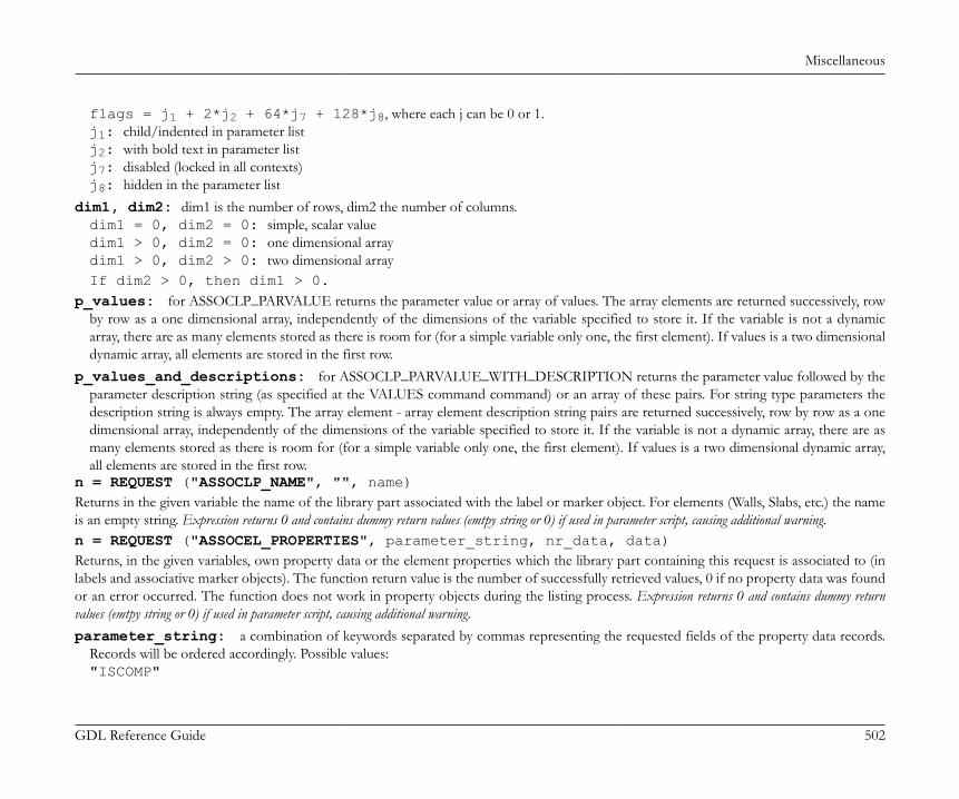
Miscellaneous
GDL Reference Guide 502
flags = j1 + 2*j2 + 64*j7 + 128*j8, where each j can be 0 or 1.j1: child/indented in parameter listj2: with bold text in parameter listj7: disabled (locked in all contexts)j8: hidden in the parameter list
dim1, dim2: dim1 is the number of rows, dim2 the number of columns.dim1 = 0, dim2 = 0: simple, scalar valuedim1 > 0, dim2 = 0: one dimensional arraydim1 > 0, dim2 > 0: two dimensional arrayIf dim2 > 0, then dim1 > 0.
p_values: for ASSOCLP_PARVALUE returns the parameter value or array of values. The array elements are returned successively, rowby row as a one dimensional array, independently of the dimensions of the variable specified to store it. If the variable is not a dynamicarray, there are as many elements stored as there is room for (for a simple variable only one, the first element). If values is a two dimensionaldynamic array, all elements are stored in the first row.
p_values_and_descriptions: for ASSOCLP_PARVALUE_WITH_DESCRIPTION returns the parameter value followed by theparameter description string (as specified at the VALUES command command) or an array of these pairs. For string type parameters thedescription string is always empty. The array element - array element description string pairs are returned successively, row by row as a onedimensional array, independently of the dimensions of the variable specified to store it. If the variable is not a dynamic array, there are asmany elements stored as there is room for (for a simple variable only one, the first element). If values is a two dimensional dynamic array,all elements are stored in the first row.
n = REQUEST ("ASSOCLP_NAME", "", name)Returns in the given variable the name of the library part associated with the label or marker object. For elements (Walls, Slabs, etc.) the nameis an empty string. Expression returns 0 and contains dummy return values (emtpy string or 0) if used in parameter script, causing additional warning.n = REQUEST ("ASSOCEL_PROPERTIES", parameter_string, nr_data, data)Returns, in the given variables, own property data or the element properties which the library part containing this request is associated to (inlabels and associative marker objects). The function return value is the number of successfully retrieved values, 0 if no property data was foundor an error occurred. The function does not work in property objects during the listing process. Expression returns 0 and contains dummy returnvalues (emtpy string or 0) if used in parameter script, causing additional warning.parameter_string: a combination of keywords separated by commas representing the requested fields of the property data records.
Records will be ordered accordingly. Possible values:"ISCOMP"

Miscellaneous
GDL Reference Guide 503
"DBSETNAME""KEYCODE""KEYNAME""CODE""NAME""FULLNAME""QUANTITY""TOTQUANTITY""UNITCODE""UNITNAME""UNITFORMATSTR""PROPOBJNAME"
nr_data: returns the number of the data items.data: returns the property data, records containing and being ordered by the fields specified in the parameter string. Values are returned as
a one dimensional array which contains the requested record fields successively, independently of the dimensions of the variable specified tostore it. If the variable is not a dynamic array, there are as many elements stored as there is room for (in case of a simple variable only one,the first element). If values is a two dimensional dynamic array, all elements are stored in the first row.
Example 11:DIM DATA []n = REQUEST ("ASSOCEL_PROPERTIES", "iscomp, code, name", nr, data)IF nr = 0 THEN TEXT2 0, 0, "No properties"ELSE j = 0 FOR i = 1 TO nr IF i MOD 3 = 0 THEN TEXT2 0, -j, DATA [i] ! name j = j + 1 ENDIF NEXT iENDIF
n = REQUEST ("REFERENCE_LEVEL_DATA", "", name1, elev1, name2, elev2, name3, elev3, name4, elev4)

Miscellaneous
GDL Reference Guide 504
Returns in the given variables the names and elevations of the reference levels as set in the Options/Project Preferences/Reference Levelsdialog. The function return value is the number of successfully retrieved values, 0 if an error occurred.n = REQUEST ("ANCESTRY_INFO", expr, name [, guid, parent_name1, parent_guid1, ... parent_namen, parent_guidn)Ancestry information on a library part. Expression returns 0 and contains dummy return values (emtpy string or 0) if used in parameter script, causing additionalwarning.If expr = 0, returns in the given variables the name and the globally unique identifier of the library part containing this request function.Optionally the function returns the names and globally unique identifiers of the parents of the library part (parent_namei, parent_guidi). If theparent templates are not loaded their names will be empty strings.If expr = 1, returns information on the library part replaced by the template containing this function. In this case if the template is not actuallyreplacing, no values are returned.The return value of the request is the number of successfully retrieved values.
Example 12:DIM strings[]n = REQUEST ("ANCESTRY_INFO", 1, name, guid, strings)IF n > 2 THEN ! data of replaced library part TEXT2 0, -1, "replacing: " + name + ' ' + guid ! parents l = -2 FOR i = 1 TO n - 2 STEP 2 TEXT2 0, l, strings [i] l = l - 1 NEXT iENDIF
n = REQUEST ("TEXTBLOCK_INFO", textblock_name, width, height)Returns in the given variables the sizes in x and y direction of a text block previously defined via the TEXTBLOCK command. The sizes are inmm or in m in model space depending on the fixed_height parameter value of TEXTBLOCK (millimeters if 1, meters in model space if 0 ). Ifwidth was 0, the request returns the calculated width and height, if width was specified in the text block definition, returns the calculated heightcorresponding to that width. Expression returns 0 and contains dummy return values (emtpy string or 0) if used in parameter script, causing additional warning.

Miscellaneous
GDL Reference Guide 505
n = REQUEST{2} ("Material_info", name_or_index, param_name, value_or_values)Returns information in the given variable(s) on a parameter (or extra parameter, see the section called “Additional Data”) of the specifiedmaterial. RGB information is returned in three separate variables, texture information is returned in the following variables: file_name, width,height, mask, rotation_angle corresponding to the texture definition. All other parameter information is returned in single variables. Expressionreturns 0 and contains dummy return values (emtpy string or 0) if used in parameter script, causing additional warning. Possible material parameter namescorresponding to parameters of the material definition:param_name:"gs_mat_surface_rgb": surface R, G, B [0.0..1.0]"gs_mat_surface_r": surface R [0.0..1.0]"gs_mat_surface_g": surface G [0.0..1.0]"gs_mat_surface_b": surface B [0.0..1.0]"gs_mat_ambient": ambient coefficient [0.0..1.0]"gs_mat_diffuse": diffuse coefficient [0.0..1.0]"gs_mat_specular": specular coefficient [0.0..1.0]"gs_mat_transparent": transparent coefficient [0.0..1.0]"gs_mat_shining": shininess [0.0..100.0]"gs_mat_transp_att": transparency attenuation [0.0..4.0]"gs_mat_specular_rgb": specular color R, G, B [0.0..1.0]"gs_mat_specular_r": specular color R [0.0..1.0]"gs_mat_specular_g": specular color G [0.0..1.0]"gs_mat_specular_b": specular color B [0.0..1.0]"gs_mat_emission_rgb": emission color R, G, B [0.0..1.0]"gs_mat_emission_r": emission color R [0.0..1.0]"gs_mat_emission_g": emission color G [0.0..1.0]"gs_mat_emission_b": emission color B [0.0..1.0]"gs_mat_emission_att": emission attenuation [0.0..65.5]"gs_mat_fill_ind": fill index"gs_mat_fillcolor_ind": fill color index"gs_mat_texture": texture index

Miscellaneous
GDL Reference Guide 506
Example 13:n = REQUEST{2} ("Material_info", "Brick-Face", "gs_mat_ambient", a)n = REQUEST{2} ("Material_info", 1, "gs_mat_surface_rgb", r, g, b)n = REQUEST{2} ("Material_info", "Brick-Face", "gs_mat_texture", file_name, w, h, mask, alpha)n = REQUEST{2} ("Material_info", "My-Material", "my_extra_parameter", e)
n = REQUEST{2} ("Building_Material_info", name_or_index, param_name, value_or_values)Returns information in the given variable(s) on a parameter of the specified building material. Expression returns 0 and contains dummy return values(emtpy string or 0) if used in parameter script, causing additional warning. Possible building material parameter names corresponding to parameters ofthe building material definition:param_name:"gs_bmat_id": building material id"gs_bmat_surface": building material surface index"gs_bmat_description": building material description"gs_bmat_manufacturer": building material manufacturer"gs_bmat_collisiondetection": building material participates in collision detection (0 or 1)"gs_bmat_intersectionpriority": building material intersection priority"gs_bmat_cutFill_properties": building material cut fill properties (cut fill index number, cut fill foreground pen index number,cut fill background pen index number)"gs_bmat_physical_properties": building material physical properties (thermal conductivity, density, heat capacity, embodiedenergy, embodied carbon)
Example 14:n = REQUEST{2} ("Building_Material_info", "Brick", "gs_bmat_id", id)n = REQUEST{2} ("Building_Material_info", "Brick", "gs_bmat_surface", index)n = REQUEST{2} ("Building_Material_info", "Brick", "gs_bmat_physical_properties", thermalConductivity, density, heatCapacity, embodiedEnergy, embodiedCarbon)
n = REQUEST ("FONTNAMES_LIST", "", fontnames)Returns in the given variables the fontnames available on the current computer (with character codes included). This list (or any part of thislist) can be used in a VALUES command to set up a fontname popup. The function return value is the number of successfully retrieved values,0 if an error occurred.
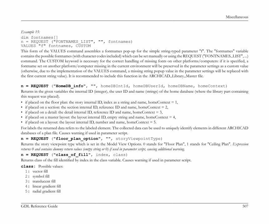
Miscellaneous
GDL Reference Guide 507
Example 15:dim fontnames[]n = REQUEST ("FONTNAMES_LIST", "", fontnames)VALUES "f" fontnames, CUSTOMThis form of the VALUES command assembles a fontnames pop-up for the simple string-typed parameter "f". The "fontnames" variablecontains the possible fontnames (with character codes included) which can be set manually or using the REQUEST ("FONTNAMES_LIST", ...)command. The CUSTOM keyword is necessary for the correct handling of missing fonts on other platforms/computers: if it is specified, afontname set on another platform/computer missing in the current environment will be preserved in the parameter settings as a custom value(otherwise, due to the implementation of the VALUES command, a missing string popup value in the parameter settings will be replaced withthe first current string value). It is recommended to include this function in the ARCHICAD_Library_Master file.
n = REQUEST ("HomeDB_info", "", homeDBIntId, homeDBUserId, homeDBName, homeContext)Returns in the given variables the internal ID (integer), the user ID and name (strings) of the home database (where the library part containingthis request was placed).• if placed on the floor plan: the story internal ID, index as a string and name, homeContext = 1,• if placed on a section: the section internal ID, reference ID and name, homeContext = 2,• if placed on a detail: the detail internal ID, reference ID and name, homeContext = 3,• if placed on a master layout: the layout internal ID, empty string and name, homeContext = 4,• if placed on a layout: the layout internal ID, number and name, homeContext = 5.For labels the returned data refers to the labeled element. The collected data can be used to uniquely identify elements in different ARCHICADdatabases of a plan file. Causes warning if used in parameter script.n = REQUEST ("floor_plan_option", "", storyViewpointType)Returns the story viewpoint type which is set in the Model View Options. 0 stands for "Floor Plan", 1 stands for "Ceiling Plan". Expressionreturns 0 and contains dummy return values (emtpy string or 0) if used in parameter script, causing additional warning.n = REQUEST ("class_of_fill", index, class)Returns class of the fill identified by index in the class variable. Causes warning if used in parameter script.class: Possible values:1: vector fill2: symbol fill3: translucent fill4: linear gradient fill5: radial gradient fill
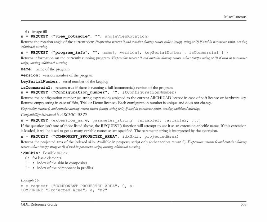
Miscellaneous
GDL Reference Guide 508
6: image filln = REQUEST ("view_rotangle", "", angleViewRotation)Returns the rotation angle of the current view. Expression returns 0 and contains dummy return values (emtpy string or 0) if used in parameter script, causingadditional warning.n = REQUEST ("program_info", "", name[, version[, keySerialNumber[, isCommercial]]])Returns information on the currently running program. Expression returns 0 and contains dummy return values (emtpy string or 0) if used in parameterscript, causing additional warning.name: name of the programversion: version number of the programkeySerialNumber: serial number of the keyplugisCommercial: returns true if there is running a full (commercial) version of the programn = REQUEST ("Configuration_number", "", stConfigurationNumber)Returns the configuration number (as string expression) assigned to the current ARCHICAD license in case of soft license or hardware key.Returns empty string in case of Edu, Trial or Demo licenses. Each configuration number is unique and does not change.Expression returns 0 and contains dummy return values (emtpy string or 0) if used in parameter script, causing additional warning.Compatibility: introduced in ARCHICAD 20.n = REQUEST (extension_name, parameter_string, variable1, variable2, ...)If the question isn’t one of those listed above, the REQUEST() function will attempt to use it as an extension-specific name. If this extensionis loaded, it will be used to get as many variable names as are specified. The parameter string is interpreted by the extension.n = REQUEST ("COMPONENT_PROJECTED_AREA", idxSkin, projectedArea)Returns the projected area of the indexed skin. Available in property script only (other scripts return 0). Expression returns 0 and contains dummyreturn values (emtpy string or 0) if used in parameter script, causing additional warning.idxSkin: Possible values:0: for basic elements1- : index of the skin in composites1- : index of the component in profiles
Example 16:n = request ("COMPONENT_PROJECTED_AREA", 0, a)COMPONENT "Projected Area", a, "m2"
Miscellaneous
GDL Reference Guide 509
Used in property script, first request the area of the skin, then create a component using the returned value.
n = REQUEST ("COMPONENT_VOLUME", idxSkin, skinVolume)Returns the volume of the indexed skin/component. Available in property script only (other scripts return 0). Expression returns 0 and containsdummy return values (emtpy string or 0) if used in parameter script, causing additional warning.idxSkin: Possible values:0: for basic elements1- : index of the skin in composites1- : index of the component in profiles
Example 17:n = request ("COMPONENT_VOLUME", 0, v)COMPONENT "Volume", v, "m3"Used in property script, first request the volume of the skin, then create a component using the returned value.
n = REQUEST ("DateTime", format_string, datetimestring)Returns the current date and time as a formatted string in datetimestring. Uses the DateTime Add-On, opening and closing the requiredchannel.format_string: Format string, described at paramString parameter of the section called “Opening Channel” .datetimestring: the formatted string is returned in this variableThe requests cause warning if used in parameter script.
Profile Requestsn = REQUEST ("Name_of_Profile", index, name)Returns in the name variable the profile name identified by index. Expression returns 0 and contains dummy return values (emtpy string or 0) if usedin parameter script, causing additional warning.Compatibility: introduced in ARCHICAD 21.n = REQUEST ("Profile_components", name_or_index, nComponents, compType1, compType2, ..., compTypen)Returns the number (nComponents) and component types (compTypen) of the profile identified by name or index. Expression returns 0 andcontains dummy return values (emtpy string or 0) if used in parameter script, causing additional warning.
Miscellaneous
GDL Reference Guide 510
compTypei: Possible values of profile component types:0: core1: finish2: other
Compatibility: introduced in ARCHICAD 21.
Example 1:_nComponents = 0dim _componentTypes[]n = REQUEST ("Profile_components", myProfileIdx, _nComponents, _componentTypes
n = REQUEST ("Profile_default_boundingbox", name_or_index, xmin, ymin, xmax, ymax)Returns the 2 defining coordinate point of the original bounding rectangle relative to the origo of the profile identified by name or index.Expression returns 0 and contains dummy return values (emtpy string or 0) if used in parameter script, causing additional warning.Compatibility: introduced in ARCHICAD 21.n = REQUEST ("Profile_default_geometry", name_or_index, n1, n2, ..., nm, x11, y11, edgeVisible11, vertEdgeVisible11, additionalStatus11, ..., x1n1, y1n1, edgeVisible1n1, vertEdgeVisible1n1, additionalStatus1n1, x21, y21, edgeVisible21, vertEdgeVisible21, additionalStatus21, ..., x2n2, y2n2, edgeVisible2n2, vertEdgeVisible2n2, additionalStatus2n2, ..., xm1, ym1, edgeVisiblem1, vertEdgeVisiblem1, additionalStatusm1, ..., xmnm, ymnm, edgeVisiblemnm, vertEdgeVisiblemnm, additionalStatusmnm)Returns the original geometric data of the profile identified by name or index. Expression returns 0 and contains dummy return values (emtpy stringor 0) if used in parameter script, causing additional warning.n1...ni: then number of contour nodes in each profile component. The total number of profile components (m) can be returned by
the "Profile_components" request.edgeVisiblei: contour starting from i node is visible.vertEdgeVisiblei: vertical edge starting from i node is visible, usable in 3D (0 in case of segmented polygon).additionalStatusi: used for segments and arcs of the polyline (set centerpoint = 900, arc using centerpoint and angle = 4000, etc.),
or to mark the contour end control point (-1, this case the vertEdgeVisiblei and edgeVisiblei are set to 0 automatically).The status parameters returned in this structure support different status type definitions of poly2, cprism, tube. Each format can be calculatedwith the following method:
Miscellaneous
GDL Reference Guide 511
Example 2:poly2Status = edgeVisible + additionalStatusprismStatus = additionalStatustubeStatus = additionalStatusif additionalStatus >= 0 then ! not contour end if edgeVisible then prismStatus = prismStatus + 15 ! j1, j2, j3, j4 endif if verticalEdgeVisible = 0 then prismStatus = prismStatus+ 64 ! j7 ! in tube, lateral edges starting from the node are used for showing the contour tubeStatus = tubeStatus + 1 endifendif
Compatibility: introduced in ARCHICAD 21.n = REQUEST{4} ("Profile_component_info", name_or_index, component_ind, param_name, value)Returns a requested attribute value of a dedicated component (by component_ind) of the profile identified by name or index. Expressionreturns 0 and contains dummy return values (emtpy string or 0) if used in parameter script, causing additional warning.The component_ind must be in the valid range of nComponents (defined by "Profile_components" request).param_name: addresses attribute settings of Profile Manager, returned in value"gs_profile_bmat": building material index of the component"gs_profile_surface": override surface index of the component (in case of active override settings; returns the surface of thebuilding material otherwise)"gs_profile_showoutline": "Show Outline" setting of the component"gs_profile_outlinetype": "Outline Type" setting of the component"gs_profile_outlinepen": "Outline Pen" setting of the component
Return attribute values can be used in any attribute related command, such as POLY2_B{6}, where contour sections of the polygon can becustomized individually.Compatibility: introduced in ARCHICAD 21.n = REQUEST{4} ("Profile_component_info", name_or_index, component_ind, param_name, value1, value2, ..., valuen)Returns requested attributes of all edges in the dedicated component (by component_ind) of the profile identified by name or index.Expression returns 0 and contains dummy return values (emtpy string or 0) if used in parameter script, causing additional warning.
Miscellaneous
GDL Reference Guide 512
The component_ind must be in the valid range of nComponents (defined by "Profile_components" request).param_name: addresses attribute settings of Profile Manager, returned in value"gs_profile_comp_surfaces": individual surface indexes of edges of the component"gs_profile_comp_pens": individual pen indexes of edges of the component"gs_profile_comp_linetypes": individual linetype indexes of edges of the component
Return attribute values can be used in any attribute related command, such as POLY2_B{6}, where contour sections of the polygon can becustomized individually.Compatibility: introduced in ARCHICAD 21.
Deprecated Requestsn = REQUEST ("Constr_Fills_display", "", optionVal)Expression returns 0 and contains dummy return values (emtpy string or 0) if used in parameter script, causing additional warning.Compatibility up till ARCHICAD 19: returns in the given variable the value of the Cut Fills Display option as set in the Document/ Set Model View/ ModelView Options. (previous Construction Fills).Compatibility starting from ARCHICAD 20: the returned value is always 6 by default (Cut fill patterns: as in Settings).optionVal: cut fill display code.1: Show cut fill contours only (previous Empty)2: Show cut fill contours only with separator lines (previous No Fills)4: Cut fill patterns: Solid (previous Solid)6: Cut fill patterns: as in Settings (previous Vectorial Hatching)
n = REQUEST ("internal_ID", "", id)Always returns 1. Use GLOB_INTGUID global variable instead.
APPLICATION QUERY OPTIONSn = APPLICATION_QUERY (extension_name, parameter_string, variable1, variable2, ...)Below is a list of request functions ARCHICAD can provide with the help of the APPLICATION_QUERY command. These request optionsare given in the extension_name and the parameter_string parameter of the command. Note, that the query options and return values ofan APPLICATION_QUERY may vary according to the execution context.The use of the following application query types in parameter script is not supported. These queries cause GDL warnings starting fromARCHICAD 19, and will return either 0 or empty string starting from the next versions. The restriction applies to:• "document_feature"
Miscellaneous
GDL Reference Guide 513
Document featureThis command can return features of the active document/view. Currently there is only one feature it can return - the view direction of thedocument. These type of queries are restricted from the parameter script and cause GDL warnings.
View directionn = APPLICATION_QUERY ("document_feature", "view_direction", type)This command returns the viewing direction of the current document type in which the object is being visualized. This command has noadditional parameters.type: Returned type values:"vertical_only": for floor plan"horizontal_only": for section and elevation generated from 3D (not when the object is placed into a S/E)"free": for 3D and 3D document"none""unset"
MEP SystemThis command returns MEP system types and information about MEP systems. It has more functions which can be addressed via theparameter_string parameter:
Get MEP SystemsDIM d[2][]n = APPLICATION_QUERY ("MEPSYSTEM", "GetMEPSystems(domain)", d)domain: MEP classification index (DuctWork – 1, PipeWork – 2) (GDL defines the MEP classifications based on connector class)d: Array of values:[2*k-1]: MEP system index[2*k]: MEP system name
n: Number of MEP systems multiplied by 2.
Get Domainn = APPLICATION_QUERY ("MEPSYSTEM", "GetDomain(idx)", d)idx: MEP system index

Miscellaneous
GDL Reference Guide 514
d: domains (integer)1: DuctWork2: PipeWork3: Duct- and PipeWork4: Cabling5: DuctWork and Cabling6: PipeWork and Cabling7: DuctWork, PipeWork and Cabling
n: 1 if successful, 0 otherwise
Get Contour Penn = APPLICATION_QUERY ("MEPSYSTEM", "GetContourPen(idx)", pen)idx: MEP system indexpen: contour pen index (integer)n: 1 if successful, 0 otherwise
Get Fill Penn = APPLICATION_QUERY ("MEPSYSTEM", "GetFillPen(idx)", pen)idx: MEP system indexpen: fill pen index (integer)n: 1 if successful, 0 otherwise
Get Background Penn = APPLICATION_QUERY ("MEPSYSTEM", "GetBgPen(idx)", pen)idx: MEP system indexpen: background pen index (integer)n: 1 if successful, 0 otherwise
Get Fill Typen = APPLICATION_QUERY ("MEPSYSTEM", "GetFillType(idx)", filltype)
Miscellaneous
GDL Reference Guide 515
idx: MEP system indexfilltype: fill type index (integer)n: 1 if successful, 0 otherwise
Get Center Line Typen = APPLICATION_QUERY ("MEPSYSTEM", "GetCenterLineType(idx)", line)idx: MEP system indexline: center line type index (integer)n: 1 if successful, 0 otherwise
Get Center Line Penn = APPLICATION_QUERY ("MEPSYSTEM", "GetCenterLinePen(idx)", pen)idx: MEP system indexpen: center line pen index (integer)n: 1 if successful, 0 otherwise
Get System Materialn = APPLICATION_QUERY ("MEPSYSTEM", "GetSystemMaterial(idx)", material)idx: MEP system indexmaterial: system material index (integer)n: 1 if successful, 0 otherwise
Get Insulation Materialn = APPLICATION_QUERY ("MEPSYSTEM", "GetInsulationMaterial(idx)", material)idx: MEP system indexmaterial: insulation material index (integer)n: 1 if successful, 0 otherwise
Miscellaneous
GDL Reference Guide 516
MEP ModelerThis command returns whether MEP modeler is active. It has one function which can be addressed via the parameter_string parameter:
Is Availablen = APPLICATION_QUERY ("MEPMODELER", "IsAvailable()", isavailable)isavailable: MEP Modeler is present (integer)n: 1 if successful, 0 otherwise
MEP Connection TypeThis command returns the connection types and the styles of connection types. It has two functions which can be addressed via theparameter_string parameter:
Get Connection TypesDIM d[2][]n = APPLICATION_QUERY ("MEPCONNECTIONTYPE", "GetConnectionTypes(connectorClass)", d)connectorClass: connector class (Duct – 1, Pipe – 2, Cable carrier – 3)d: Array of values:[2*k-1]: connection type GUID[2*k]: connection type name
n: Number of connection types multiplied by 2.
Get Connection Type StyleDIM d[]n = APPLICATION_QUERY ("MEPCONNECTIONTYPE", "GetConnectionTypeStyle(connectorClass)", d)connectorClass: connector class (Duct – 1, Pipe – 2, Cable carrier – 3)d: Array of values:[]: connection type styles
n: Number of connection types.

Miscellaneous
GDL Reference Guide 517
MEP Flexible SegmentThis command returns the geometry of flexible segments. It has four functions which can be addressed via the parameter_string parameter:
Start Sectioningn = APPLICATION_QUERY ("MEPFLEXIBLESEGMENT", "StartSectioning()", r)Indicates that sectioning has begun.r: not usedn: 1 if successful, 0 otherwise
Add Control Pointn = APPLICATION_QUERY ("MEPFLEXIBLESEGMENT", "AddControlPoint(x; y; z)", r)Provides a control point to the add-on.AddControlPoint:x: X coordinate of the control pointy: Y coordinate of the control pointz: Z coordinate of the control point
r: not usedn: 1 if successful, 0 otherwise
Add Direction and Width Vectorn = APPLICATION_QUERY ("MEPFLEXIBLESEGMENT", "AddDirectionAndWidthVector(i; dx; dy; dz; wx; wy; wz)", r)Provides the direction and side vectors of the ends of spline to add-on. It is called twice.AddDirectionAndWidthVector:i: id of port (1: 0. port, 2: 1. port etc.)dx: X component of direction vector of the portdy: Y component of direction vector of the portdz: Z component of direction vector of the portwx: X component of side vector of the portwy: Y component of side vector of the portwz: Z component of side vector of the port

Miscellaneous
GDL Reference Guide 518
r: not usedn: 1 if successful, 0 otherwise
End SectioningDIM d[]n = APPLICATION_QUERY ("MEPFLEXIBLESEGMENT", "EndSectioning(res)", d)Getting of the result of sectioning.res: resolution of sectioningd: Array of values:[9*k-8]: X position of k segment[9*k-7]: Y position of k segment[9*k-6]: Z position of k segment[9*k-5]: X component of tangent vector of k segment[9*k-4]: Y component of tangent vector of k segment[9*k-3]: Z component of tangent vector of k segment[9*k-2]: X component of normal vector k segment[9*k-1]: Y component of normal vector k segment[9*k]: Z component of normal vector k segment
n: Number of segments
MEP BendThis command returns the geometry of flexible segment. It has four functions which can be addressed via the parameter_string parameter:
Start Sectioningn = APPLICATION_QUERY ("MEPBEND", "GetBendTypeNames()", d)d: Bend Type Names (examples of INT version)"Radius""Square Throat""Mitered""45° Throat with 45° Heel""45° Throat with 90° Heel"

Miscellaneous
GDL Reference Guide 519
"45° Throat with Radius Heel""Radius Throat with 90° Heel""Pleated""Stamped""Segmented""Segmented Standing Seam"
n: 1 if successful, 0 otherwise
Parameter ScriptThis command can return various conditions of the parameter script. Currently there is only one feature it can return - the distinction of thefirst run.
First Occasion in Progressn = APPLICATION_QUERY ("parameter_script", "firstoccasion_in_progress", isFirstRun)This command returns whether the current run is the first run or a consequence of a previous execution of the parameter script which changedsome parameters. This command has no additional parameters.The distinction may be important when a part of the parameter script executes a triggered event - e.g. it handles the pushing of a function button.isFirstRun: The returned value shows whether the current run is the first run
Tags and CategoriesThese commands return the folder names, parameter names and parameter values of "Tags and Categories" tabpage. The order of parametersis the same as on the tabpage. There are two possible extension_names in these commands:• "OwnCustomParameters" returns parameters of the object• "ParentCustomParameters" returns parameters of the object's parent
Get Parameter Folder NamesDIM folderNamesArray[] ! [idString 1],[shortNameString 1],[longNameString 1], ! ... ! [idString n],[shortNameString n],[longNameString n]n = APPLICATION_QUERY (extension_name, "GetParameterFolderNames()", folderNamesArray)Returns the folder names of Tags and Categories parameters.folderNamesArray: String array which contains the foldernames of Tags and Categories

Miscellaneous
GDL Reference Guide 520
n+1: Number of folders including the root folder
Get Parameter NamesDIM parNamesArray[] ! [idString 1],[shortNameString 1],[longNameString 1], ! ... ! [idString n],[shortNameString n],[longNameString n]n = APPLICATION_QUERY (extension_name, "GetParameterNames(folderNamesArray[i][1])", parNamesArray)Returns the names of Tags and Categories parameters.The first column of the array returned at the section called “Get Parameter Folder Names”.parNamesArray: String array which contains the names of Tags and Categories parametersn: Number of parameters
Get Parametersn = APPLICATION_QUERY (extension_name, "GetParameter(parNamesArray[i][2])", parValue)Returns the values of Tags and Categories parameters.The second column of the array returned at the section called “Get Parameter Names”.parValue: String which contains the value of Tags and Categories parametersn: 1 if successful, 0 otherwise
Library managerThis command can return various features of the library manager.
Ies filesn = APPLICATION_QUERY ("LIBRARY_MANAGER", "IES_FILES", ies_files_list)This command returns the list of file names with .ies extensions loaded with the active libraries.
User image filesn = APPLICATION_QUERY ("LIBRARY_MANAGER", "USER_IMAGE_FILES", image_files_list)This command returns the list of user-provided image file names loaded with the active libraries (image files which are not in the dedicatedfolders with names containing [TImg]*, [BImg]*, [UImg]*, or [HImg]*)

Miscellaneous
GDL Reference Guide 521
GDL STYLE GUIDE
IntroductionThis document contains the GDL coding standard of GRAPHISOFT, which mainly sets the formal requirements for writing source code.It also describes a few rules and recommendations for the content. You have to obey these rules in order to produce manageable scripts; bydefault every declarative or imperative sentence is a rule, except where 'recommendation' (or avoidable, optional, etc.) is explicitly stated.This document was created to establish a common format of GDL scripting. The GDL language is insensitive to the character case and mostof the whitespace characters. As a result, lots of coding practices and standards exist. This gets intolerable, when such practices meet in thesame project or organization. The following sections describe the GRAPHISOFT company standard, which remains purely a recommendationfor non-GRAPHISOFT related developers. The supposed format will not be included in the GDL language's constraints ever.
Naming Conventions
General rulesBecause of the subtype hierarchy, the child library parts automatically inherit all parameters of the parent. (Read more about subtypes andparameter in the ARCHICAD User Guide). Parameters are identified by their name, so inherited and original parameters can have the samename. It is the responsibility of the library author to avoid conflicts by using descriptive parameter names prefixed with abbreviated library partnames. For handler parameters and user-defined parameters, GRAPHISOFT has introduced a parameter naming convention in its libraries.
NoteHandlers add extra functionality to library parts (e.g. doors and windows cut holes in walls). Parameter names with the prefix ac_are reserved for special parameters associated with ARCHICAD handlers (e.g. ac_corner_window). Check the standard ARCHICADLibrary subtype templates for the complete list.
Standard GRAPHISOFT parameter names are marked with the gs_ prefix (e.g. gs_frame_pen). Please check the ARCHICAD library parts forreference. Use these parameters in your GDL scripts to ensure full compatibility with GRAPHISOFT libraries.FM_ is reserved for ArchiFM (e.g. FM_Type).
Variable namesVariable and parameter names should be related with the function of the parameter.mixedCase: starts with a lowercase letter; every new word should start with an uppercase letter. E.g.: size, bRotAngle180,upperLeftCorner
Miscellaneous
GDL Reference Guide 522
Don't use one or two letter variable names - no one will know what you meant.You should use a prefix in generally used variable names to denote general categories. This can spare time when someone needs to find out thetype of a variable or parameter. Don't forget to replace the prefix if you change the meaning of a variable.
Table 6. Variable name prefixesPrefix Meaning Example
i General integer value / integer index iRiser
n Integer value - amount of something nRiser
b Boolean value bHandrail
st String type value stPanelTypes
x X coordinate of a point xRailPos
y Y coordinate of a point yRailPos
pen Pen color penContour
lt Linetype ltContour
fill Fill type fillMainBody
mat Material type matCover
Using underscores (_) is recommended for distinguishing variables and parameters in the same script: use single underscore (_) prefix for avariable in a script, and double (__) for a variable declared and used only inside a subroutine section. Do not use underscores in the beginningof parameter names, or to separate words in a name. Historical names coming from subtypes are exceptions.Example
_iDoorTypes = iDoorTypes! "_iDoorTypes" variable gets the value of "iDoorTypes" parametergosub "exampleScript"end
"exampleScript": __iDoorTypes = _iDoorTypes * 3 ! "__iDoorTypes" subroutine variable gets the value of 3 times "_iDoorTypes" variablereturn

Miscellaneous
GDL Reference Guide 523
Capitalization• Commands should be written consistently lowercase or uppercase according to your taste. GRAPHISOFT recommends lowercase.• GDL global variables should always be written uppercase for easier script reading.• The following keywords should be lowercase: call, goto, gosub, parameters.
Expressions• Space should be used in front of and behind the following binary operators:
◦ arithmetical: *, /, % (mod), +, -, ^ (**)◦ logical: & (and), | (or), @ (excluding or), =, <> (#), <, <=, >, >=◦ assignment: =E.g.:a = (b + c % d) * e
• No spaces are allowed in front of and behind the following unary operators:◦ subscripting: array[25] Note: avoid space inside brackets (array[ 5]) to make "find" function easier◦ logical not: not(x)◦ unary minus, unary plus: -x, +x
• Function calls should have a space in front of the opening parenthesis of the parameter list, and behind every comma separating theparameters:abs (signedLength)minimum = min (a, 25 * b, c)
• When testing equality with constants (e.g. i = 5) the constant should be the second operand.• When assigning values to Boolean variables the logical expression should be parenthesized:bBoolValue = (i > j)
• Do not use the Boolean result of logical negation of integer values or variables. E.g. instead of if not(iIntVal) then please use ifiIntVal = 0 then. (Of course, Boolean variables and expressions can be negated, e.g. if not(bBoolVal) then).
• Do not compare Boolean variables and expressions to true or false; use the value of Boolean or its negated value:bBoolVal = 1if bBoolVal then ! instead of: if bBoolVal = 1 ...endifif not(bBoolVal) then ! instead of: if bBoolVal = 0 ...endif
• Complex expressions (e.g. where and and or are both present) should be parenthesized to clarify precedence.
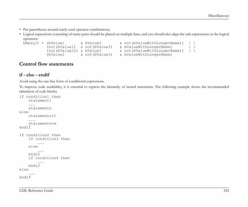
Miscellaneous
GDL Reference Guide 524
• Put parentheses around rarely used operator combinations.• Logical expressions consisting of many parts should be placed on multiple lines, and you should also align the sub-expressions or the logical
operators:bResult = (bValue1 & bValue3 & not(bValueWithLongerName)) | \ (not(bValue1) & not(bValue3) & bValueWithLongerName) | \ (not(bValuel2) & bValue3 & not(bValueWithLongerName)) | \ (bValue2 & not(bValue3) & bValueWithLongerName)
Control flow statements
if - else - endifAvoid using the one line form of conditional expressions.To improve code readability, it is essential to express the hierarchy of nested statements. The following example shows the recommendedtabulation of code blocks.if condition1 then statement1 ... statementnelse statementn+1 ... statementn+mendif
if condition2 then if condition3 then ... else ... endif if condition4 then ... endifelse ...endif

Miscellaneous
GDL Reference Guide 525
for - next, do - while, while - endwhile, repeat - untilTo improve code readability, it is essential to express the hierarchy of nested statements. The following example shows the recommendedtabulation of code blocks.for i = initialValue to endValue statement1 ... statementnnext i
do ... for i = initialValue to endValue statement1 ... statementn next i ... bCondition = ... ...while bCondition
SubroutinesPieces of code that are needed more than once should be turned into subroutines. This makes later corrections less risky, and the code morestructured. The label of the subroutine should correspond with its function. Do not use numbers as names, it makes the code unreadable.Variables used and declared only inside a subroutine should start with double underscore.Style (italic texts should be replaced implicitly):
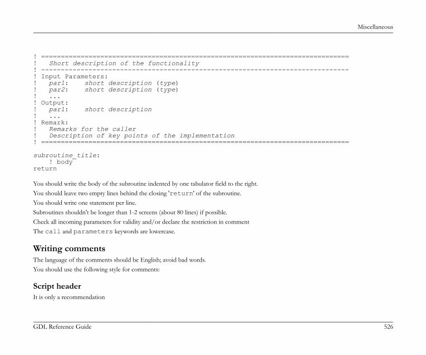
Miscellaneous
GDL Reference Guide 526
! ==============================================================================! Short description of the functionality! ------------------------------------------------------------------------------! Input Parameters:! par1: short description (type)! par2: short description (type)! ...! Output:! par1: short description! ...! Remark:! Remarks for the caller! Description of key points of the implementation! ==============================================================================
subroutine_title: ! bodyreturn You should write the body of the subroutine indented by one tabulator field to the right.You should leave two empty lines behind the closing 'return' of the subroutine.You should write one statement per line.Subroutines shouldn't be longer than 1-2 screens (about 80 lines) if possible.Check all incoming parameters for validity and/or declare the restriction in commentThe call and parameters keywords are lowercase.
Writing commentsThe language of the comments should be English; avoid bad words.You should use the following style for comments:
Script headerIt is only a recommendation

Miscellaneous
GDL Reference Guide 527
! <contact person initials>! ==============================================================================! One sentence description of the purpose of the script! ------------------------------------------------------------------------------! Input Parameters:! par1: description of the parameter (integer)! par2: description of the parameter (1 / -1)! par3: description of the parameter (0 / 1)! ...! Output: [if a macro returns values]! [1]: description of the value (type)! [2]: description of the value (type)! [ ... NSP]: original stack elements! Remark:! Longer description.! Note for the caller! ============================================================================== Any code can come only after this.
Section divide
! ==============================================================================! Section name! ============================================================================== The length of the full comment line is 80 characters.For the subroutines you should always explain the meaning of non-trivial parameters and the return value. E.g. for indices always indicate therange (starts from 0 or 1, any special values, etc.).Example in the section called “Subroutines”You should always indicate with the TODO keyword if you leave something unfinished, it's easy to search for later:
n = 5 ! TODO: set initials; it will be computed from the length
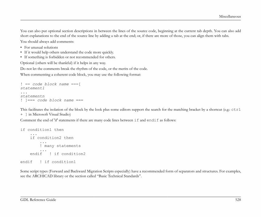
Miscellaneous
GDL Reference Guide 528
You can also put optional section descriptions in between the lines of the source code, beginning at the current tab depth. You can also addshort explanations to the end of the source line by adding a tab at the end; or, if there are more of those, you can align them with tabs.You should always add comments:• For unusual solutions• If it would help others understand the code more quickly.• If something is forbidden or not recommended for others.Optional (others will be thankful) if it helps in any way.Do not let the comments break the rhythm of the code, or the merits of the code.When commenting a coherent code block, you may use the following format:
! == code block name ===[statement1...statementn! ]=== code block name === This facilitates the isolation of the block by the look plus some editors support the search for the matching bracket by a shortcut (e.g.: ctrl+ ] in Microsoft Visual Studio)Comment the end of 'if' statements if there are many code lines between if and endif as follows:
if condition1 then ... if condition2 then ... ! many statements ... endif ! if condition2
endif ! if condition1 Some script types (Forward and Backward Migration Scripts especially) have a recommended form of separators and structures. For examples,see the ARCHICAD library or the section called “Basic Technical Standards”.
Miscellaneous
GDL Reference Guide 529
Script structureSet your editor to use 4 character wide tabs. Spaces should never be used to tabulate lines. Instead, use spaces to adjust expressions to eachother inline.The maximum length of the lines is 120 characters. Statements shouldn't even get close to this number. In case they do, you get a warning.All file name references are case sensitive in scripts, the extensions accordingly.Values used multiple times should be calculated directly before the block of usage if it can be well localized or at the beginning of the scriptotherwise. There is no compromise. Calculate complex values only once to spare calculation time by storing them in variables (but do not wastevariables unnecessary) or in the transformation stack (add, rot, etc.).The object scripts are linear which makes them clearer. Subroutines should only break it when a calculation or model generation segment isneeded more than once, or for script readability. Avoiding coding the same thing twice is an important principle in all programming languages.Redundancy makes later changes a lot more difficult.Try not to use huge choice branches, instead prepare the data for a calculation or generation command in smaller choice-blocks, where youcan avoid redundancy easier.
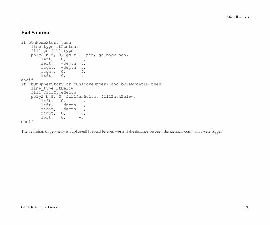
Miscellaneous
GDL Reference Guide 530
Bad Solution
if bOnHomeStory then line_type ltContour fill gs_fill_type poly2_b 5, 3, gs_fill_pen, gs_back_pen, left, 0, 1, left, -depth, 1, right, -depth, 1, right, 0, 0, left, 0, -1endifif (bOnUpperStory or bOnAboveUpper) and bDrawContBB then line_type ltBelow fill fillTypeBelow poly2_b 5, 3, fillPenBelow, fillBackBelow, left, 0, 1, left, -depth, 1, right, -depth, 1, right, 0, 0, left, 0, -1endif The definition of geometry is duplicated! It could be even worse if the distance between the identical commands were bigger.
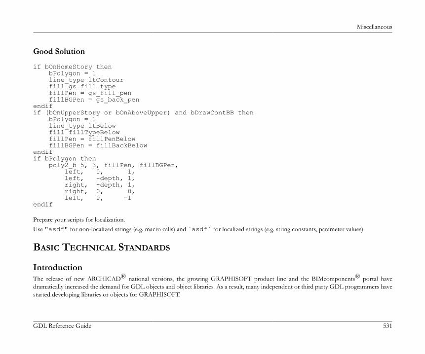
Miscellaneous
GDL Reference Guide 531
Good Solution
if bOnHomeStory then bPolygon = 1 line_type ltContour fill gs_fill_type fillPen = gs_fill_pen fillBGPen = gs_back_penendifif (bOnUpperStory or bOnAboveUpper) and bDrawContBB then bPolygon = 1 line_type ltBelow fill fillTypeBelow fillPen = fillPenBelow fillBGPen = fillBackBelowendifif bPolygon then poly2_b 5, 3, fillPen, fillBGPen, left, 0, 1, left, -depth, 1, right, -depth, 1, right, 0, 0, left, 0, -1endif Prepare your scripts for localization.Use "asdf" for non-localized strings (e.g. macro calls) and `asdf` for localized strings (e.g. string constants, parameter values).
BASIC TECHNICAL STANDARDS
IntroductionThe release of new ARCHICAD® national versions, the growing GRAPHISOFT product line and the BIMcomponents® portal havedramatically increased the demand for GDL objects and object libraries. As a result, many independent or third party GDL programmers havestarted developing libraries or objects for GRAPHISOFT.
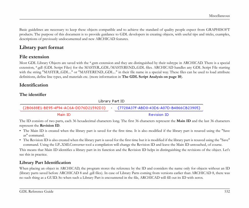
Miscellaneous
GDL Reference Guide 532
Basic guidelines are necessary to keep these objects compatible and to achieve the standard of quality people expect from GRAPHISOFTproducts. The purpose of this document is to provide guidance to GDL developers in creating objects, with useful tips and tricks, examples,descriptions of previously undocumented and new ARCHICAD features.
Library part format
File extensionMost GDL Library Objects are saved with the *.gsm extension and they are distinguished by their subtype in ARCHICAD. There is a specialextension, *.gdl (GDL Script Files) for the MASTER_GDL/MASTEREND_GDL files. ARCHICAD handles any GDL Script File startingwith the string "MASTER_GDL..." or "MASTEREND_GDL..." in their file name in a special way. These files can be used to load attributedefinitions, define line types, and materials etc. (more information in The GDL Script Analysis on page 10).
Identification
The identifier
The ID consists of two parts, each 36 hexadecimal characters long. The first 36 characters represent the Main ID and the last 36 charactersrepresent the Revision ID.• The Main ID is created when the library part is saved for the first time. It is also modified if the library part is resaved using the "Save
as" command.• The Revision ID is also created when the library part is saved for the first time but it is modified if the library part is resaved using the "Save"
command. Using the LP_XMLConverter tool a compilation will change the Revision ID and leave the Main ID untouched, of course.This means that Main ID identifies a library part in its function and the Revision ID helps in distinguishing the revisions of the object. Let'ssee this in practice.
Library Part IdentificationWhen placing an object in ARCHICAD, the program stores the reference by the ID and considers the name only for objects without an ID(library parts saved before ARCHICAD 8 and .gdl files). In case of Library Parts coming from versions earlier than ARCHICAD 8, there wasno such thing as a GUID. So when such a Library Part is encountered in the file, ARCHICAD will fill out its ID with zeros.

Miscellaneous
GDL Reference Guide 533
When loading a library, ARCHICAD uses the following hierarchical criteria for matching loaded library parts to objects already placed in theproject:• In case the stored ID is valid:
• ARCHICAD tries to get an exact match of both parts of the ID• Failing that, ARCHICAD tries to match the first part of the ID, which is the Main ID.• In case it doesn't find one matching, it starts to check other elements' Migration Table values to find a substitute.• Finally, when loading files saved before ARCHICAD 12, ARCHICAD tries to match by library part name.
• In case the stored ID is zero, the identification procedure tries to match by name only.The same process is executed when looking for macros in a placed element as every library part contains a lookup table for its called macros'GUIDs. Naturally, when saving an object containing macro calls, this table is collected using a name-based search in the currently loaded library.
How to know what the exact GUID of a Library Object isFor this you have to get to know the Subtype Hierarchy dialog window. In this dialog you can see the subtype hierarchy of the currently loadedlibrary in a tree view. The main attributes - name, version, ID, file location, flags indicating if the object is template or placeable - of the selectedlibrary part are displayed in the bottom of the window.This dialog appears in 3 contexts:• Open Object by Subtype... (in File menu)• Select Subtype... (in the Library Part Editor window)• Place All Objects (in the Special menu)Naturally, you can read the ID in the XML format of the library part (location: xpointer (/Symbol/@UNID)). To get this, use theLP_XMLConverter tool.
Compatibility issuesThe most important principle is that the Main ID represents a constant functionality to the users of the library. This means that if you publisha new library part using a Main ID that is already in use by an old library part, when loading an old project with the new library, the old placedelements will be replaced by the new object. This contradicts the users' expectations, such as there will be no change in the object's parametersand their functions. If you want to change the name or the function of old parameters, generate a new Main ID and use migration scripts toavoid ambiguity and unexpected data loss. Make sure that this new Main ID is unique - not identical with any other ID in the library.Note, that renaming an object won't make it incompatible with its past self for ARCHICAD as long as their MainIDs remain identical. Similarly,giving the name of an existing library part to a new one (with a new ID) will not make them compatible.This issue effects the localization of libraries, too. If you have string type controlling parameters, the relevant values will differ between nationalversions. For example: if you are unaware of the problem, loading a German plan file with the Danish sibling library will change the generated

Miscellaneous
GDL Reference Guide 534
elements since some control parameters have meaningless values. There are two solutions. The easy way is to declare that the German andDanish libraries have nothing to do with each other and to change the Main IDs in localization consequently. The second - and more userfriendly - solution is to create an integer type control parameter acting as string (see VALUES). These integer parameters are determinant, thevisible string descriptions are just an input method for them (therefore localizations can be different, but the true meaning will stay the same).When writing a script, the integer parameter values should be used.The following example code features a detail level integer parameter acting as a string type:
! Master script:dim stDetlevel3DDesc [3]stDetlevel3DDesc[1]=`Detailed`stDetlevel3DDesc[2]=`Simple`stDetlevel3DDesc[3]=`Off`
! iDetlevel3D constantsDETLEVEL3D_DETAILED = 1DETLEVEL3D_SIMPLE = 2DETLEVEL3D_OFF = 3
! Parameter script:values{2} "iDetlevel3D" DETLEVEL3D_DETAILED, stDetlevel3DDesc[1], DETLEVEL3D_SIMPLE, stDetlevel3DDesc[2], DETLEVEL3D_OFF, stDetlevel3DDesc[3]
Migrating ElementsIt is possible to maintain a link between the old and the new, updated version (with new Main ID) of a library part by using migration scripts(the section called “Forward Migration script”, the section called “Backward Migration script”) and the section called “Migration table”.In these scripts you can define which library part substitutes which (by connecting the old and new Main ID-s), and how to update the newobject's parameter values based on the old one (or vice versa). You can set rules for the migration to happen only under certain parametricconditions. If the subject of the migration meets these, the upgrade or downgrade is possible, otherwise it will not be an option.
Miscellaneous
GDL Reference Guide 535
Generally, it is possible for the subject of the migration to have one or more successors (or ancestors in backward migration) depending onparameter settings. The case is a little different when migrating Zone Stamps, though. One type of Zone Stamp can be linked to many ZoneCategories. But each category can use only one kind of Zone Stamp. When migrating a Zone Stamp, the Category stays the same. If the route ofmigration diverges ("Zone Old" is upgraded to "Zone New 1", or to "Zone New 2", depending on different parameter settings), it is possibleto get a Category with two different Stamps linked. While this is a valid result regarding the migration process, it is an inconsistent situationfor ARCHICAD. Make sure you only migrate Zone Stamps in a direct way, to avoid this.
General scripting issues
Numeric types - PrecisionBefore ARCHICAD 9 all numeric values were stored internally as floating point values which resulted in imprecise vaules. This meant thatinteger values were - a little - imprecisely stored. From ARCHICAD 9 integers - and hence GDL parameter types that are best described withintegers - are correctly stored internally as integers.Parameter types internally stored as an Integer:Integer,Boolean,Material,Line type,Fillpattern,Pencolor,Intensity (Light)
Parameter types internally stored as a Floating-point number:Length,Angle,Real,RGB Color component (Light)
GDL variables still don't require type definition, the type is determined during the interpretation from the value to be loaded into the variable.The output of numeric operators now have a type. You should consult the GDL Manual for this information.The programmer can safely compare integer types with the equality operator. In fact, from ARCHICAD 9 warnings are now issued, if aprogrammer tries to directly compare floating point values with integer values using the equality operator. For equality-comparisons of floating-point numbers use a small epsilon value meaning the precision of the comparison. For equality-comparisons of a floating-point number andan integer use the round_int function.

Miscellaneous
GDL Reference Guide 536
Below some sample methods of testing for equivalence between different numeric types are described:
iDummy = 1 * 2if iDummy = 2 then ! valid comparison, it is true, these statements will be executed ...endif
dDummy = 1.5 + 0.5if dDummy = 2 then ! you never know if it is true, don't trust such comparisons ...endif
dDummy = 1.1 * 2if dDummy = 2.2 then ! you never know if it is true, don't trust such comparisons ...endif
! EPS = 0.0001 -> in the master scriptdDummy = 1.1 * 2if abs (dDummy - 2.2) < EPS then ! valid comparison, it is true, these statements will be executed ...endif
dDummy = 1.5 * 2if round_int (dDummy) = 3 then ! valid comparison, it is true, these statements will be executed ...endif
Miscellaneous
GDL Reference Guide 537
Trigonometry functionsWhile GDL scripting, you may need various trigonometry functions. The following functions are directly available from GDL: cos, sin,tan, acs, asn, atn.All other functions can be easily derived as follows.
Secant Sec(X) = 1 / cos(X)Cosecant Cosec(X) = 1 / sin(X)Cotangent Cotan(X) = 1 / tan(X)Inv. Sine Arcsin(X) = atn(X / Sqr(-X * X + 1))Inv. Cosine Arccos(X) = atn(-X / sqr(-X * X + 1)) + 2 * atn(1)Inv. Secant Arcsec(X) = atn(X / sqr(X * X - 1)) + sgn((X) -1) * 2*atn(1)Inv. Cosecant Arccosec(X) = atn(X / sqr(X*X - 1)) + (sgn(X) - 1) * 2*atn(1)Inv. Cotangent Arccotan(X) = atn(X) + 2 * atn(1)Hyp. Sine HSin(X) = (exp(X) - exp(-X)) / 2Hyp. Cosine HCos(X) = (exp(X) + exp(-X)) / 2Hyp. Tangent HTan(X) = (exp(X) - exp(-X)) / (exp(X) + exp(-X))Hyp. Secant HSec(X) = 2 / (exp(X) + exp(-X))Hyp. Cosecant HCosec(X) = 2 / (exp(X) - exp(-X))Hyp. Cotangent HCotan(X) = (exp(X) + exp(-X)) / (exp(X) - exp(-X))Inv. Hyp. Sine HArcsin(X) = log(X + sqr(X * X + 1))Inv. Hyp. Cosine HArccos(X) = log(X + sqr(X * X - 1))Inv. Hyp. Tangent HArctan(X) = log((1 + X) / (1 - X)) / 2Inv. Hyp. Secant HArcsec(X) = log((sqr(-X * X + 1) + 1) / X)Inv. Hyp. Cosecant HArccosec(X) = log((sgn(X) * sqr(X * X + 1) +1) / X)Inv. Hyp. Cotangent HArccotan(X) = log((X + 1) / (X - 1)) / 2 Note:
Logarithm to base N LogN(X) = log(X) / log(N)
GDL warningsLike any other programming language, GDL has a syntax and logic to be followed. If there is a mistake in syntax, the programmer gets an errormessage. If there is something confusing, or some unexpected thing happens when running the script, a GDL warning is sent out.You can choose WHERE you want to send these messages in Options/Work Environment/Model Rebuild Options:

Miscellaneous
GDL Reference Guide 538
• Interrupt with error messages: a dialog pops up at every problem• Write Report: the message is written in the Report windowYou can choose WHAT you want to send out as message: this setting is available in the Library Developer menu, called "Check Library PartScripts for Warnings". When enabled, not only errors, but warnings get reported as well according to the WHERE settings.You can also choose WHEN you want to see warning messages. This can be set in the Library Developer menu as well, called "Always SendGDL Messages". Turning this feature on, every time GDL is executed, the warnings and errors get force-reported anyway. Leaving it off,the warning report contexts stay as usual.Note, that using some combinations of the above switches can result in difficulties: for example, having the "Always Send GDL Messages"and the "Interrupt with error messages" enabled together may prevent the execution of something as "simple" as moving an editable hotspot,popping up dialogs all the time.Pressing "Check script" in the library part editor, if there is a problem with your script using the current parameter settings, you will alwaysget a warning or error message popup window. Using the PRINT command, or the GDL debugger may help a lot locating mistakes hardto find otherwise.Note that the line numbers in the GDL warnings refer to the script which contains the problem.Parsing errors must be handled with extra care. These denote the first line in which the parsing gets impossible but the actual problems maybe some lines before.ExampleThe interpreter detects the missing statement first at the endif and stops there; though the problem is obviously around line 4 where anendif is really missing.
if condition1 then if condition2 then ! do something
! do something - BUT WE MISSED AN 'endif'else ! a potentially long code blockendif

Miscellaneous
GDL Reference Guide 539
Here are some examples of the latest warning messages developed, with some explanation:
Warning message Possible explanation
Simple parameter redeclared as an array specifying a simple parameter in an object and using it as an array inthe called macro
Undefined parentId "id" used in UI_PAGE definition missing parent ID in tabpage hierarchy
View/Project dependent global "globalName" used in parameter script see the section called “Global Variables”
Request "requestName" used in parameter script see the section called “REQUEST Options”
Application query "applicationQueryName" used in parameter script see the section called “Application Query Options”
Possibly unwanted parameter type change a parameter receives a value not supported by its original type
Hotspot and Hotline IDs
Purpose of hotspot/hotline/hotarc identificationIn ARCHICAD the hotspot/hotline/hotarc identification is introduced to support associative dimensioning in section. Via this feature adimensioning item can refer to any of a GDL object's hotspots/hotlines. It will become an important issue when the number of hotspots/hotlines changes between the object's different parameterization states.
Problem of old-school hotspots/hotlinesIf the programmer doesn't specify hotspot/hotline/hotarc IDs - or if he sets them to 0 - ARCHICAD will assign continuously increasing ordinalnumbers. This solution is correct for static objects but causes dimensioning problems when some hotspots/hotlines appear or hide betweenparameter set-ups. Namely, the IDs will be rearranged so they will change, and the associative dimensioning items - in section - will go astray.
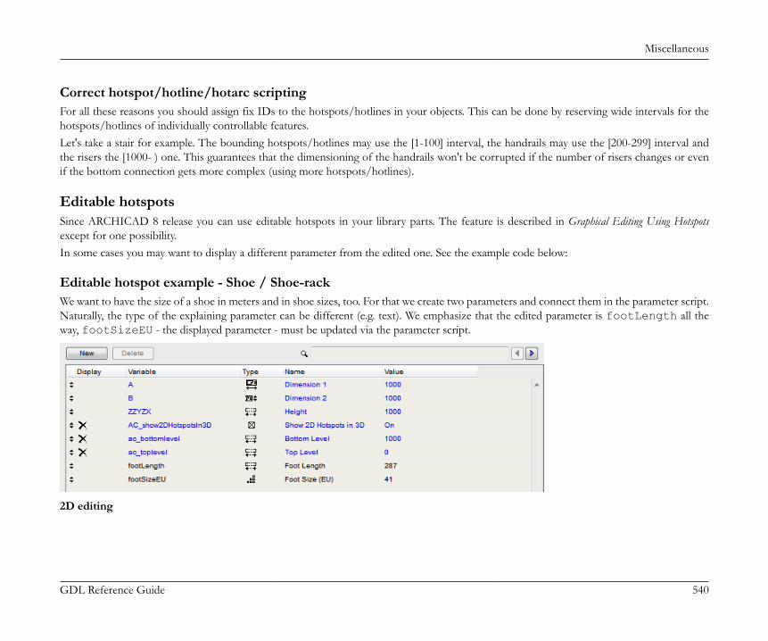
Miscellaneous
GDL Reference Guide 540
Correct hotspot/hotline/hotarc scriptingFor all these reasons you should assign fix IDs to the hotspots/hotlines in your objects. This can be done by reserving wide intervals for thehotspots/hotlines of individually controllable features.Let's take a stair for example. The bounding hotspots/hotlines may use the [1-100] interval, the handrails may use the [200-299] interval andthe risers the [1000- ) one. This guarantees that the dimensioning of the handrails won't be corrupted if the number of risers changes or evenif the bottom connection gets more complex (using more hotspots/hotlines).
Editable hotspotsSince ARCHICAD 8 release you can use editable hotspots in your library parts. The feature is described in Graphical Editing Using Hotspotsexcept for one possibility.In some cases you may want to display a different parameter from the edited one. See the example code below:
Editable hotspot example - Shoe / Shoe-rackWe want to have the size of a shoe in meters and in shoe sizes, too. For that we create two parameters and connect them in the parameter script.Naturally, the type of the explaining parameter can be different (e.g. text). We emphasize that the edited parameter is footLength all theway, footSizeEU - the displayed parameter - must be updated via the parameter script.
2D editing

Miscellaneous
GDL Reference Guide 541
Parameter script
DIM lengthValues[10]DIM sizeValues[10]for i = 1 to 10 sizeValues[i] = i + 35 lengthValues[i] = (i + 35) * 0.007next i
values "footLength" lengthValuesvalues "footSizeEU" sizeValues
if GLOB_MODPAR_NAME = "footLength" then parameters footSizeEU = round_int (footLength / 0.007)else if GLOB_MODPAR_NAME = "footSizeEU" or GLOB_MODPAR_NAME = "" then parameters footLength = footSizeEU * 0.007 endifendif 2D script
Miscellaneous
GDL Reference Guide 542
rect2 0, 0, footLength * 0.4, footLength ! or a more realistic shoe model
hotspot2 0, 0, 1, footLength, 1 + 256, footSizeEUhotspot2 0, footLength, 2, footLength, 2, footSizeEUhotspot2 0, -0.1, 3, footLength, 3
GDL execution contextsARCHICAD lets the GDL object know about the context it is being displayed or used in. The next global variables are used for this purpose:• GLOB_VIEW_TYPE to determine the active view• GLOB_PREVIEW_MODE to determine the active preview• GLOB_FEEDBACK_MODE for editing context indication• GLOB_SEO_TOOL_MODE for solid element operations context indicationFor the possible values refer the the section called “General environment information” and the following list:GLOB_VIEW_TYPE = 2 - 2D, floor planThe model is displayed in the standard 2D floor plan. In a 3D script this means that the model is projected to 2D via the project2Dcommand. This is the main use of an object - this 2D model must be always correct and efficient.If GLOB_FEEDBACK_MODE = 1 then the model is displayed via feedback lines on the 2D floor plan during the hotspot editing of theobject. This model is drawn many times in a single second throughout the user interaction. This implies that the model should represent theessential parts of the object only. Note, that texts (generated by text2 command) are not refreshed in feedback mode - since it would slowdown the output.GLOB_VIEW_TYPE = 3 - 3D viewThe 3D model is displayed in the standard 3D model window or it is the source of photorealistic rendering. This view should omit internaldetails of the object, since these cannot be seen anyway. This is the second most important use of an object - the 3D model must be alwayscorrect and efficient. This target type demands correct outside look.If GLOB_FEEDBACK_MODE = 1 then the 3D model is displayed via feedback lines in the 3D model window during the hotspot editingof the object. This model is drawn many times in a single second throughout the user interaction. This implies that the model should representthe essential and visible parts of the object only.GLOB_VIEW_TYPE = 4 - section or GLOB_VIEW_TYPE = 5 - elevationThe 3D model is displayed in a section/elevation window. For these views, the object should generate internal details which are unnecessaryfor every other view type.
Miscellaneous
GDL Reference Guide 543
If GLOB_FEEDBACK_MODE = 1 then the 3D model is displayed via feedback lines in a section/elevation window during the hotspotediting of the object. This model is drawn many times in a single second throughout the user interaction. This implies that the model shouldrepresent the essential and visible parts of the object only.GLOB_VIEW_TYPE = 6 - 3D documentThe 3D model is displayed in an axonometric window as a drawing. This is used for documentation, dimensioning in 3D.GLOB_VIEW_TYPE = 7 - detail drawingThe model is used in a detailed drawing window. The model can be more detailed than in other views consequently. The 2D and 3D modelsare not distinguished - that information can be derived from the script type.GLOB_VIEW_TYPE = 8 - layoutThe model is used in a layout window, with its print display. The model should show its printing look. The 2D and 3D models are notdistinguished - that information can be derived from the script type.If GLOB_FEEDBACK_MODE = 1 then the model is displayed via feedback lines in a layout window during the hotspot editing of theobject. This model is drawn many times in a single second throughout the user interaction. This implies that the model should represent theessential and visible parts of the object only.GLOB_VIEW_TYPE = 9 - calculation and/or GLOB_PREVIEW_MODE = 2 - listingThe 3D model is used for surface and volume calculation by the listing engine. This context is the proper place to do some model alterationsfor listing. E.g. you can generate extra bodies to raise the surface to be painted and the amount of required paint. Use the combination of the2 globals for the desired result in calculation and listing model generation.GLOB_PREVIEW_MODE = 1 - settings dialogThe model is displayed in the Object Settings Dialog's preview box. The 2D and 3D models are not distinguished - that information can bederived from the script type. The object should provide a fast, rough preview of the model considering the limited size of the preview.GLOB_SEO_TOOL_MODE = 1 generating as an operator for Solid Element OperationsThe generated 3D model is used as a parameter for solid (CSG) operations. This can be useful, when the object's space demand is larger thanthe object itself. E.g. when you subtract a stair from a slab, you'd expect that the stair cuts a hole for the walking people, too. To achieve this,in this context the stair should generate a model containing that walking space.
Communicating values with ARCHICADThere are two directions of parameter value flow between ARCHICAD and the library part. The first direction means that the ARCHICADinforms the library part about an attribute of its context (e.g. the drawing scale of the project or the thickness of the wall a window is placedinto). The second direction is when the library part asserts something about itself which instructs ARCHICAD to change that something inthe direct context of the object (e.g. the depth a wall end cuts in the wall).

Miscellaneous
GDL Reference Guide 544
Information flow from ARCHICADThere are 3 channels of information coming from ARCHICAD: global variables, parameters with predefined names and directly called values.
Global variablesGlobal variables are filled by ARCHICAD according to the current project settings and to the placement context of the object. Note, that notall globals are filled in every context and view.For the complete list of global variables and their relevant restrictions in certain scripts, consult the section called “Global Variables”.
Fix named optional parametersThe newer method of ARCHICAD for providing information is the method of fixed named optional parameters. If a given library part has aparameter with a name and type matching any optional parameter, ARCHICAD sets its value according to its function.Refer the section called “Parameters set by ARCHICAD” in the section called “Fix named optional parameters” to learn the ARCHICAD defined library partparameters.
Requests and Application QueriesFor rarely used, special information, library parts use Request calls or Application Queries in their scripts. Unlike global variables, these onlygive a return value when the containing actual scripts runs. Note, that most requests and queries should be avoided in a parameter script, or amaster script run as a parameter script. If used in those scripts, the validity of the returned value or the function can not be guaranteed.Refer the section called “REQUEST Options” and the section called “Application Query Options” to learn more about options, parameter script compatibility andsyntax.
Information coming from the library partARCHICAD needs certain informations to use the library parts correctly. These informations depend on the function and the context, and arestored in the built-in ARCHICAD subtypes as parameters with predefined name and function. In addition to built-in ARCHICAD subtypessome functions might need fixed named optional parameters.Consult the fix parameters of built-in subtypes and the section called “Parameters read by ARCHICAD” in the section called “Fix named optional parameters”to get a view of the possibilities.
Model View Options, Library GlobalThe display of library parts in the plan may depend on the current view.
Miscellaneous
GDL Reference Guide 545
Internal Model View OptionsThe view's internal settings are available via GDL global variables (e.g. GLOB_SCALE, GLOB_STRUCTURE_DISPLAY) and request options(e.g. "window_show_dim", "door_show_dim", "floor_plan_option", "view_rotangle").
Library Global View OptionsFrom ARCHICAD 13 on, you can define view options from your library. These options are stored into each view and they are returnedaccordingly.The following properties/parameters/options should be stored in view dependent library globals:• showing/hiding opening lines• showing/hiding minimal spaces• pen and other view attributes which shouldn't be changed individually for the sake of uniformity (e.g. minimal spaces)• showing/hiding specific accessory elements (e.g. knobs, handles)• setting 2D symbol types for object groupsThings which should NOT be stored in view dependent library globals: general values for the whole project, general values for the wholecountry, values which may be required to be set individually for objects.To insert a tab page into the MVO dialog, you have to make a library part which is derived from the Library Global Settings (GUID:{709CC5CC-6817-4C56-A74B-BED99DDB5FFA}) subtype. This object must contain the desired global options as parameters and it musthave a user interface definition for the tab page. The width of the UI should be set to 600 pixels to match the existing panels. The height of theUI is freely definable. It may have a parameter script for connecting parameters or user interface elements.The LIBRARYGLOBAL command can be used in your placeable elements to query values of your own library global settings object dependingon the current view settings.
Script type specific issues
Master scriptWhen writing the master script you should keep in mind that it will be evaluated before the run of each script by ARCHICAD. This impliesthe following things:• Placing parameter definitions and calculations used by multiple scripts in the master script is a good idea: it reduces file size and makes
elements easily modifiable.• Be sure to put only common calculations here to avoid an unnecessary increase of the evaluation time of the libpart (remember that master
script is evaluated before each and every script).
Miscellaneous
GDL Reference Guide 546
• Avoid using the parameter buffer in the master script for effectiveness reasons.• Do not put end commands in the master script; otherwise, ARCHICAD will not run the rest of the scripts.
2D script
Execution contextThe 2D script is executed when a 2D model is generated:• 2D plan• 2D editing feedback• 2D preview in the Object Settings dialog window• Layout drawing• Layout drawing feedbackMind that most of the architectural design is done in 2D, so usually this model is the most important. This implies requirements of exact look,fast generation time and proper function when editing via hotspots.
General recommendationTry to avoid using fragments and the binary 2D format in order to make objects modifiable.2D script is much more customizable than the 2D symbol, prefer this solution. In a binary 2D symbol, the curved fills aren't stretched correctly,you don't have to face this problem in 2D scripting, either.
Defining line and fill propertiesFrom ARCHICAD 9 on you have the possibility to choose from several main categories of lines and fills from GDL. Lines and polygon segmentscan be defined as contour, inner or general; fills can be defined cut, cover or drafting. These categories are described in the ARCHICAD userdocumentation, let's see how we use them in GDL objects.Setting the correct properties for lines and fills will enable you to eliminate the display-option dependence from your scripts. Formerly, you hadto add a condition for drawing of some inner lines according to the set display option. Now you should define an inner line for that purposeand ARCHICAD will display it or not as implied by the display options.Let's see the extract of the 2D script of a window to summarize the definition cases:
Miscellaneous
GDL Reference Guide 547
! ===== Sill =====
line_property 0 ! general lines
! the sill is seen from above -> cover fillpoly2_b{2} 4, 1 + 2 * (gs_fillSillCover > 0) + 4 + 64, ......
! ===== Wall segment / Cavity Closure =====
line_property 1 ! inner linesline2 ......
line_property 2 ! wall contoursline2 ......
! wall segment is seen cut -> cut fillpoly2_b{2} 4, 2 + 4 + 8 + 16 + 32, ...
! ===== Window Frame =====
line_property 0 ! general lines
! side window frame is seen cut -> cut fillpoly2_b{2} 4, 1 + 2 * (gs_fillFrames > 0) + 4 + 32, ......
3D script
Execution contextThe 3D script is executed each time a 3D model is generated:• 3D window (wire, hidden line, solid model)• 2D plan when project2 is used to project the 3D model to 2D
Miscellaneous
GDL Reference Guide 548
• 2D section - mind the details• 3D editing feedback - optimize for speed• Operator for solid operations in 3D - ask the designer for the desired functionality• Surface and volume calculation for Listing• 3D preview in the Object Settings dialog window• Layout drawing when project2 is used to project the 3D model to 2D• Layout drawing feedback
General recommendationTry to avoid using binary format in order to make objects modifiable.Use status codes to control the visibility of the objects in hidden line views. Make the contour lines of curved surfaces visible. Hide unnecessarylines when it is possible.Define editable hotspots instead of fix ones whenever possible.Don't use del top command to make later modifications easier.Always restore the global coordinate system at the end of the 3D script and follow it with an end command to make further modificationson the object easier.
Modeling transparent bodiesUse the body -1 command between solid and transparent parts of an object to make correct shadow casting with Internal Rendering Engine(e.g., window sash with grilles).

Miscellaneous
GDL Reference Guide 549
Table 7. Examples for transparent bodies
Incorrect Correct
prism_ 10, 0.1, 0, 0, 15, 1, 0, 15, 1, 1, 15, 0, 1, 15, 0, 0, -1, 0.1, 0.1, 15, 0.9, 0.1, 15, 0.9, 0.9, 15, 0.1, 0.9, 15, 0.1, 0.1, -1
material "blueglass"
prism_ 5, 0.1, 0.1, 0.1, 15, 0.9, 0.1, 15, 0.9, 0.9, 15, 0.1, 0.9, 15, 0.1, 0.1, -1
prism_ 10, 0.1, 0, 0, 15, 1, 0, 15, 1, 1, 15, 0, 1, 15, 0, 0, -1, 0.1, 0.1, 15, 0.9, 0.1, 15, 0.9, 0.9, 15, 0.1, 0.9, 15, 0.1, 0.1, -1
body -1
material "blueglass"
prism_ 5, 0.1, 0.1, 0.1, 15, 0.9, 0.1, 15, 0.9, 0.9, 15, 0.1, 0.9, 15, 0.1, 0.1, -1
Miscellaneous
GDL Reference Guide 550
Texture mappingAlways check if texture mapping is applied correctly on your objects. If the default ARCHICAD texture mapping process doesn't produce agood result, use the coor command to set the correct method. See the case below for example.

Miscellaneous
GDL Reference Guide 551
Table 8. Example code for random and for correctly aligned tiling
Random texture Aligned texture
define texture "owntile" "T.jpg", 1, 1, 128+256, 0
define material "tilemat" 21, 0.7, 0.7, 1, 0.15, 0.95, 0, 0.0, 0, 0, ind (fill, ""), 1, ind (texture, "owntile")
material tilemat
block 1, 1, 1
define texture "owntile" "T.jpg", 1, 1, 128+256, 0
define material "tilemat" 21, 0.7, 0.7, 1, 0.15, 0.95, 0, 0.0, 0, 0, ind (fill, ""), 1, ind (texture, "owntile")
material tilemat
block 1, 1, 1
basevert 0, 0, 0vert 1, 0, 0vert 0, 1, 0vert 0, 0, 1
coor 2 + 256, -1, -2, -3, -4

Miscellaneous
GDL Reference Guide 552
In general, separate bodies which require different texture coordinate systems with a body -1 command.When using different texture mapping modes, you should take care of correct axis definitions with the vert or teve commands. The nodeorder is shown below.
You can distort the textures by setting different distances between the nodes defined by the vert or teve commands.Take care that working with different rendering engines can produce slightly different results, see the examples.Internal engine:
C4D engine:

Miscellaneous
GDL Reference Guide 553
Correct texture mapping on complicated surfaces or distorted textures can be modeled with coor and teve commands. In this way you canmake surface models only. In ARCHICAD, there is no direct texture specification. You can define a texture as a part of a material definition.This texture is used in Rendering Engines and in OpenGL – but in OpenGL we have only limited implementation of our full texture mapping,and no texture (fill) mapping in our Internal 3D Engine at all.So with TEVE command you can map a planar texture point (u,v) to a spatial geometric point (x, y, z):• (x, y, z) is measured in meters in the local coordinate system, as usual• (u, v) is measured in units in the infinite texture space. One unit is as long as the texture extent in that direction.You can give a negative or more than one value for either u or v.See the example 1:
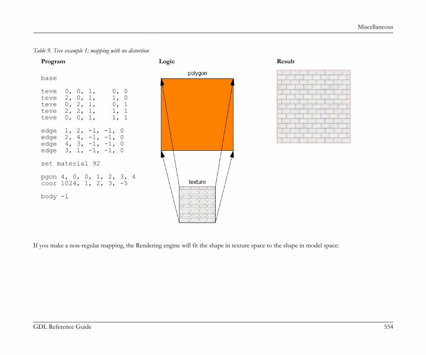
Miscellaneous
GDL Reference Guide 554
Table 9. Teve example 1: mapping with no distortion
Program Logic Result
base
teve 0, 0, 1, 0, 0teve 2, 0, 1, 1, 0teve 0, 2, 1, 0, 1teve 2, 2, 1, 1, 1teve 0, 0, 1, 1, 1
edge 1, 2, -1, -1, 0edge 2, 4, -1, -1, 0edge 4, 3, -1, -1, 0edge 3, 1, -1, -1, 0
set material 92
pgon 4, 0, 0, 1, 2, 3, 4coor 1024, 1, 2, 3, -5
body -1
If you make a non-regular mapping, the Rendering engine will fit the shape in texture space to the shape in model space:
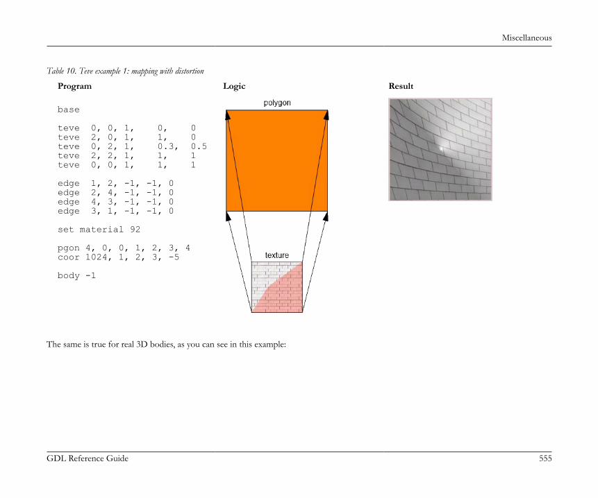
Miscellaneous
GDL Reference Guide 555
Table 10. Teve example 1: mapping with distortion
Program Logic Result
base
teve 0, 0, 1, 0, 0teve 2, 0, 1, 1, 0teve 0, 2, 1, 0.3, 0.5teve 2, 2, 1, 1, 1teve 0, 0, 1, 1, 1
edge 1, 2, -1, -1, 0edge 2, 4, -1, -1, 0edge 4, 3, -1, -1, 0edge 3, 1, -1, -1, 0
set material 92
pgon 4, 0, 0, 1, 2, 3, 4coor 1024, 1, 2, 3, -5
body -1
The same is true for real 3D bodies, as you can see in this example:
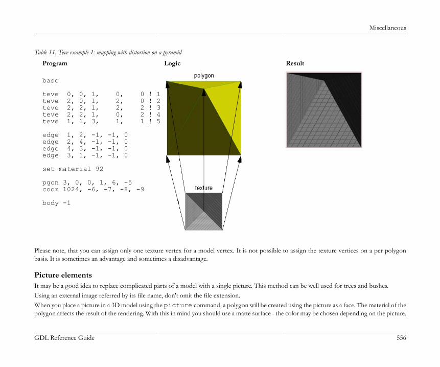
Miscellaneous
GDL Reference Guide 556
Table 11. Teve example 1: mapping with distortion on a pyramid
Program Logic Result
base
teve 0, 0, 1, 0, 0 ! 1teve 2, 0, 1, 2, 0 ! 2teve 2, 2, 1, 2, 2 ! 3teve 2, 2, 1, 0, 2 ! 4teve 1, 1, 3, 1, 1 ! 5
edge 1, 2, -1, -1, 0edge 2, 4, -1, -1, 0edge 4, 3, -1, -1, 0edge 3, 1, -1, -1, 0
set material 92
pgon 3, 0, 0, 1, 6, -5coor 1024, -6, -7, -8, -9
body -1
Please note, that you can assign only one texture vertex for a model vertex. It is not possible to assign the texture vertices on a per polygonbasis. It is sometimes an advantage and sometimes a disadvantage.
Picture elementsIt may be a good idea to replace complicated parts of a model with a single picture. This method can be well used for trees and bushes.Using an external image referred by its file name, don't omit the file extension.When you place a picture in a 3D model using the picture command, a polygon will be created using the picture as a face. The material of thepolygon affects the result of the rendering. With this in mind you should use a matte surface - the color may be chosen depending on the picture.
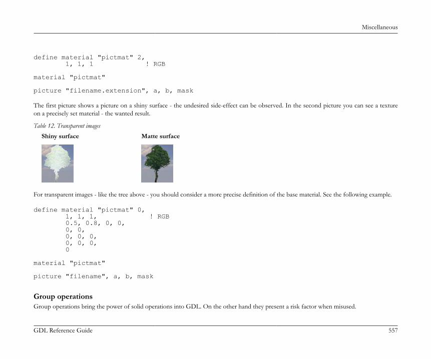
Miscellaneous
GDL Reference Guide 557
define material "pictmat" 2, 1, 1, 1 ! RGB
material "pictmat"
picture "filename.extension", a, b, mask The first picture shows a picture on a shiny surface - the undesired side-effect can be observed. In the second picture you can see a textureon a precisely set material - the wanted result.
Table 12. Transparent imagesShiny surface Matte surface
For transparent images - like the tree above - you should consider a more precise definition of the base material. See the following example.
define material "pictmat" 0, 1, 1, 1, ! RGB 0.5, 0.8, 0, 0, 0, 0, 0, 0, 0, 0, 0, 0, 0
material "pictmat"
picture "filename", a, b, mask
Group operationsGroup operations bring the power of solid operations into GDL. On the other hand they present a risk factor when misused.
Miscellaneous
GDL Reference Guide 558
An important point is that you mustn't place a group inside another one. In such situations you should define a new group like in the sourcesnippet below:subtractionResult = subgroup ("sub_operand_1", "sub_operand_2")
Parameter script
Execution contextThe parameter script is run in the following cases:• Opening the Object Settings dialog window• Changing a parameter's value in the Object Settings dialog window• Changing a parameter's value using editable hotspots (even while generating the feedback)• Stretching the object using conventional hotspots• loading step-by-step migration libraries (starting from AC18)The parameter script MAY be run on:• Dragging the object, in case the object refers to SYMB_POS_X/SYMB_POS_Y• Update Zones runs the parameter script of the affected zones if necessaryThe parameter script is NOT run on:• Rebuild• Changing scale• Changing storyEditing multiple selection may result unintended parameter values.Note that the parameter script may be run multiple times on a single user interaction. The reason for this is that the parameter script can changethe value of parameters and this requires the parameter script to be run again, and so on. Therefore it makes no sense to increase a parametervalue by one in the parameter script since you may not be able to predict the cardinality of executions.The run of the parameter script is linear, and not necessarily multiple. You can force the parameter script to start only once by checking theRun the parameter script only once option in the object's Compatibility Options panel, if you are sure you don't need it to run many times.This can make objects react faster, saving time and computing resources.
General recommendationWhen you control parameters in the parameter script, try to follow the order of additional parameters.
Miscellaneous
GDL Reference Guide 559
You can define relations between parameters using the GLOB_MODPAR_NAME value (containing the name of the last modified parameter).For example you can make a circle object for which both the radius and the diameter can be set (maybe one of them via the parameter list andthe other via editable hotspots). Don't use this possibility to define the valid range of parameters - use values command instead.Define the valid value range for all parameters using the values command.When resetting the value of a parameter in a certain condition in the Parameter Script using the parameters command, a similar statementmust be put into the Master Script. This keeps the object's display correct in cases when the parameter script is not run by the system. E.g.:
! parameter scriptif bCondition then yy = 1 parameters yy = yyendif
! master scriptif bCondition then yy = 1
Font type namesIf you want to have a string parameter - named stFont in the sample - for setting the font type for a text, use the following value list definitionto get a platform independent sound solution.
DIM fontNames[]request ("FONTNAMES_LIST", "", fontNames)values "stFont" fontNames, CUSTOM If you do this in the ARCHICAD_Library_Master.gsm object, every loaded library part with the same "stFont" parameter will automaticallyreceive the same value list.CUSTOM value is needed to deal with missing or unexpected font types.
Setting limits for array parametersArray parameters should be used for homogeneous data; i.e. all array elements should have a similar meaning.Example code snippet for limiting all components of array parameter gridXPosition to the range [1, 5] and how to use it on the UI:

Miscellaneous
GDL Reference Guide 560
! parameter scriptvalues "gridXPosition" range [1, 5]
! UI scriptfor i = 1 to nGridLines ! nGridLines: number of lines in the array parameter ui_infield{3} gridXPosition[i], xPos, yPos, infieldWidth, infieldHeight
yPos = yPos + diffYnext i
User Interface script
Execution contextThe User Interface script is displayed in only one context: the user interface tab page in the Object Settings dialog window.The script is run on the initialization of the dialog window and after each user interaction and parameter change.
General recommendationIf you want the Custom Settings page to appear in the topmost UI selector as default instead of the parameter list, push the Set as Defaultbutton (or add the "STBit_UIDefault" bit to the "StatBits" section of the XML). Otherwise the parameter list will be the starting tab. ForHierarchical pages, push the Hierarchical Pages button in the GDL Editor/UI window (or add the "STBit_UIUseHierarchicalPages" bit tothe "StatBits" section of the XML).When styling texts, note that extra small letters cannot get any style but plain. In addition, Outline and Shadow styles have no effect on Windowsplatform.Note that ARCHICAD tries to match the fonts used in dialogs with the operating systems. When scripting graphical user interfaces on Windows,leave more space around texts otherwise Mac users will see truncated texts.
Thumbnail control picturesIf you use the ui_infield command to define a thumbnail view field for value lists, be aware of the following. There should be equal sizedthumbnails for all parameter values (including empty value). Thumbnails have to be the same size at which they will be displayed otherwiseARCHICAD will distort them. We advise you to use ARCHICAD's figure tool for assembling the thumbnails into one picture file.

Miscellaneous
GDL Reference Guide 561
Table 13. Infield with picture
Input picture Output picture
A user interface picture used by only one object should be integrated in the library part file itself. This can be done using the LP_XMLConvertertool.When using an external image referred to by its file name, don't omit the file extension. This way, you will avoid errors stemming from picturesand objects having the same name.Keep all pictures used by interface scripts in the Macros folder, or embedded in the object itself. Using external images: add thefile_dependence command to make sure they are saved in archive format with the object.
Tab page handlingStarting from ARCHICAD 18, a new hierarchical paging option is available for tabpage selection. This is accessed via the UI_PAGE command,by adding some extra parameters, and setting the Hierarchical Pages parameter in the object itself. Doing so, a separate popup tabpage controlwill appear above the custom UI field. The order and hierarchy of the available pages can be defined by the ID of the pages. Root ID is always-1. The possibility to set up an "oldschool" tabpage selector within the UI page still remains available.Let's see an example script:
Miscellaneous
GDL Reference Guide 562
! Master Script
! TabIDsTABID_ROOT = -1TABID_PAGE_1 = 50TABID_PAGE_2 = 60
dim uiUsedPageIDs[][2]dim uiUsedPageNames[][2]
idxPage = 1
uiUsedPageNames[idxPage][1] = "PageName_1"uiUsedPageNames[idxPage][2] = "pageIconName_1.png"
uiUsedPageIDs[idxPage][1] = TABID_PAGE_1uiUsedPageIDs[idxPage][2] = TABID_ROOT ! Parent Page ID
idxPage = idxPage + 1
uiUsedPageNames[idxPage][1] = "PageName_2"uiUsedPageNames[idxPage][2] = "pageIconName_2.png"
uiUsedPageIDs[idxPage][1] = TABID_PAGE_2uiUsedPageIDs[idxPage][2] = TABID_PAGE_1 ! Parent Page ID
file_dependence "pageIconName_1.png"file_dependence "pageIconName_2.png"file_dependence "pageIconName_3.png"
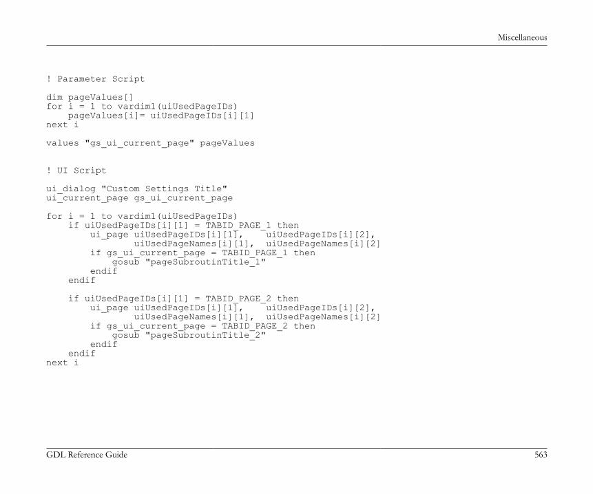
Miscellaneous
GDL Reference Guide 563
! Parameter Script
dim pageValues[]for i = 1 to vardim1(uiUsedPageIDs) pageValues[i]= uiUsedPageIDs[i][1]next i
values "gs_ui_current_page" pageValues
! UI Script
ui_dialog "Custom Settings Title"ui_current_page gs_ui_current_page
for i = 1 to vardim1(uiUsedPageIDs) if uiUsedPageIDs[i][1] = TABID_PAGE_1 then ui_page uiUsedPageIDs[i][1], uiUsedPageIDs[i][2], uiUsedPageNames[i][1], uiUsedPageNames[i][2] if gs_ui_current_page = TABID_PAGE_1 then gosub "pageSubroutinTitle_1" endif endif
if uiUsedPageIDs[i][1] = TABID_PAGE_2 then ui_page uiUsedPageIDs[i][1], uiUsedPageIDs[i][2], uiUsedPageNames[i][1], uiUsedPageNames[i][2] if gs_ui_current_page = TABID_PAGE_2 then gosub "pageSubroutinTitle_2" endif endifnext i

Miscellaneous
GDL Reference Guide 564
! ==============================================================================! Call User Interface Macro's TabPages! ==============================================================================
call "ui_customMacro" parameters all uiUsedPageIDs = uiUsedPageIDs, uiUsedPageNames = uiUsedPageNames
! ==============================================================================end ! end ! end ! end ! end ! end ! end ! end ! end ! end ! end ! end ! end ! en! ==============================================================================
! ==============================================================================! UI Page Subroutines! ==============================================================================
"pageSubroutinTitle_1": ! UI Page 1 descriptionreturn
"pageSubroutinTitle_2": ! UI Page 2 descriptionreturn
Thumbnail controls with dynamic itemsFrom ARCHICAD 10 on, a new dynamic method is available for linking control items and value list items. Using this method you can localizethe logic of the availability of parameter values to the parameter script - the control will adopt the set of available values. This dynamic linking isavailable for ui_infield{3} and ui_infield{4}. The old-style static linking is still working for static functions (using ui_infieldand ui_infield{2}).The two components of the dynamic method are:1. Define the user interface control with an option for every possible value.The example shows a popup menu control (method = 2) which uses an index image containing 2 rows and 4 columns. The sample controlsupports 8 possible values.
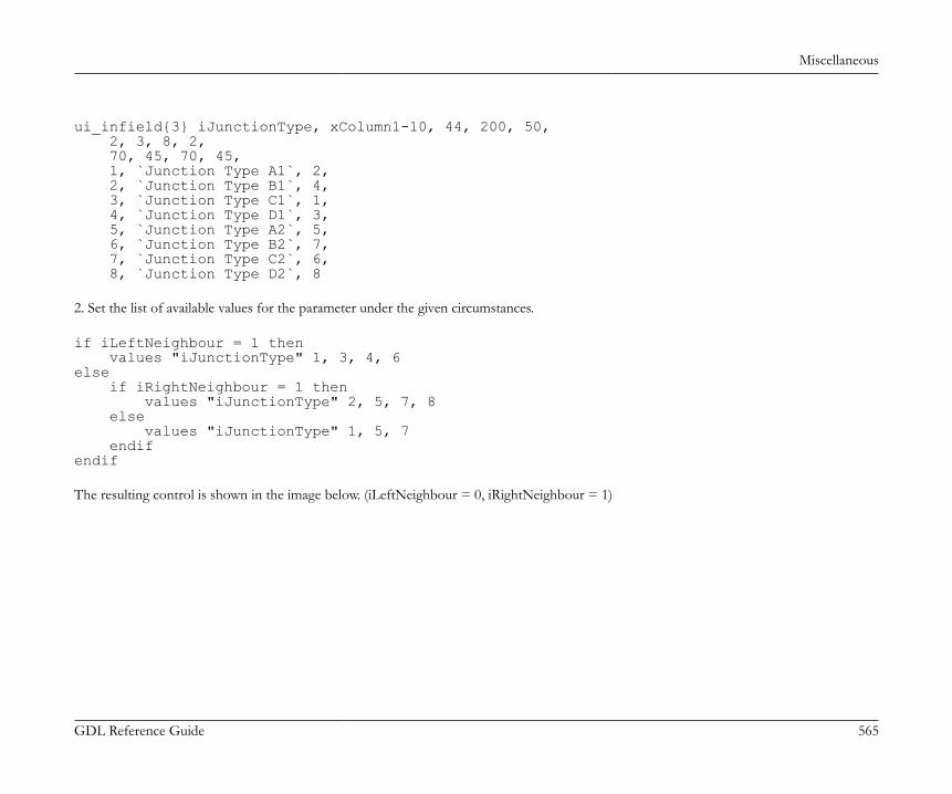
Miscellaneous
GDL Reference Guide 565
ui_infield{3} iJunctionType, xColumn1-10, 44, 200, 50, 2, 3, 8, 2, 70, 45, 70, 45, 1, `Junction Type A1`, 2, 2, `Junction Type B1`, 4, 3, `Junction Type C1`, 1, 4, `Junction Type D1`, 3, 5, `Junction Type A2`, 5, 6, `Junction Type B2`, 7, 7, `Junction Type C2`, 6, 8, `Junction Type D2`, 8 2. Set the list of available values for the parameter under the given circumstances.
if iLeftNeighbour = 1 then values "iJunctionType" 1, 3, 4, 6else if iRightNeighbour = 1 then values "iJunctionType" 2, 5, 7, 8 else values "iJunctionType" 1, 5, 7 endifendif The resulting control is shown in the image below. (iLeftNeighbour = 0, iRightNeighbour = 1)

Miscellaneous
GDL Reference Guide 566
Transparent UI picturesIn ARCHICAD 10 a new method has been introduced that can handle alpha-layer based transparent pictures. The following controls handlepictures with alpha layers correctly:• ui_pict• ui_infield{3}, method = 1 (thumbnail view control)• ui_infield{3}, method = 2 (popup with icons and texts)• ui_infield{3}, method = 3 (popup with icons only)• ui_infield{3}, method = 4 (icon radio push button)• ui_infield{4}, method = 1 (thumbnail view control)• ui_infield{4}, method = 2 (popup with icons and texts)• ui_infield{4}, method = 3 (popup with icons only)• ui_infield{4}, method = 4 (icon radio push button)
Font sizes on the UIIf you use static texts (possibly in combination with the ui_style command), be aware of the following.
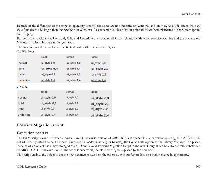
Miscellaneous
GDL Reference Guide 567
Because of the differences of the targeted operating systems, font sizes are not the same on Windows and on Mac. As a side effect, the extrasmall font size is a bit larger than the small one on Windows. As a general rule, always test user interfaces on both platforms to check overlappingand clipping.Furthermore, special styles like Bold, Italic and Underline are not allowed in combination with extra small size. Outline and Shadow are oldMacintosh styles, which are no longer used.The two pictures show the look of static texts with different sizes and styles.On Windows:
On Mac:
Forward Migration script
Execution contextThe FWM script is executed when a project saved in an earlier version of ARCHICAD is opened in a later version (starting with ARCHICAD15) with the updated library. This new library can be loaded manually or by using the Consolidate option in the Library Manager. If a placedinstance of an object has a new, changed Main ID and a valid Forward Migration Script in the new library, it can be automatically substitutedby ARCHICAD. If the execution of the script is successful, the old element gets replaced by the new one.This script enables the object to set the new parameters based on the old ones, without feature loss or a major change in appearance.

Miscellaneous
GDL Reference Guide 568
General recommendationThe first line of the script fills the FROM_GUID global variable (this contains the main ID of the original object to be migrated) into the"actualGuid" variable. You may want to use the following structure to ensure maintainability.The rest of the script is divided into subroutine calls, one for every change of GUID. Every block must have a corresponding line in theMigration Table of the object and a block in the Backward Migration script. The latest change of Main ID always has to be the last call of thisscript. In every block you set the ID to start from (_startID), and the one to end up with (_endID), define the migration logic in a subroutine(for details and GDL commands, see the GDL Reference Guide), and at the end of the block you always set the new "_endID" (or set an emptyID, which means that the upgrade process will stop at the previous block's version of the object) into the "actualGuid" variable. Example:
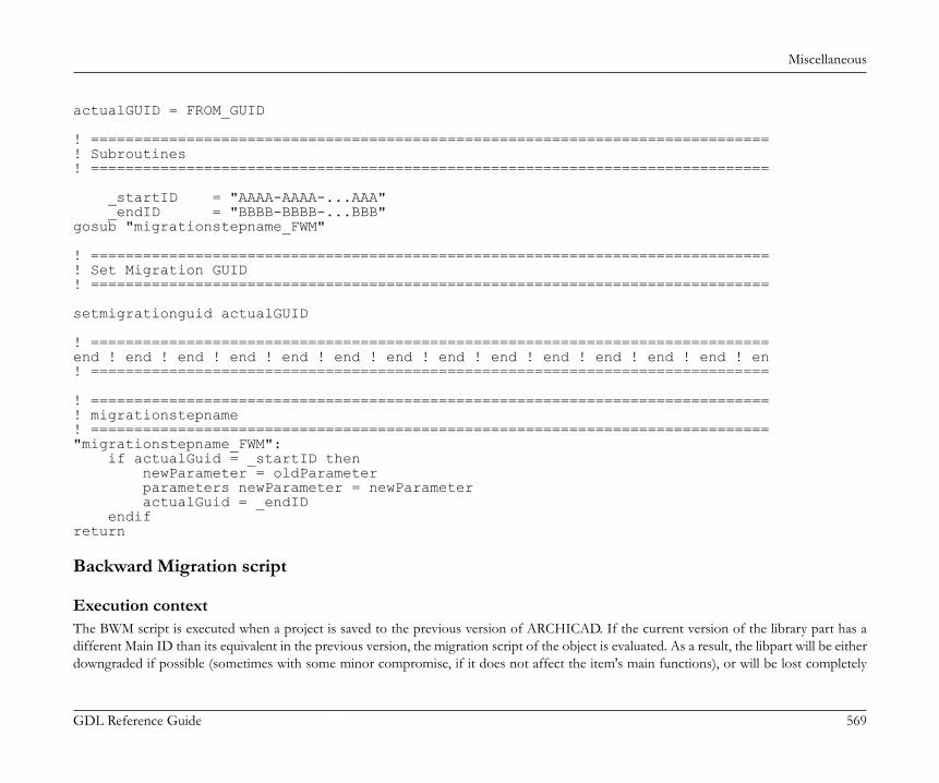
Miscellaneous
GDL Reference Guide 569
actualGUID = FROM_GUID
! ==============================================================================! Subroutines! ==============================================================================
_startID = "AAAA-AAAA-...AAA" _endID = "BBBB-BBBB-...BBB"gosub "migrationstepname_FWM"
! ==============================================================================! Set Migration GUID! ==============================================================================
setmigrationguid actualGUID
! ==============================================================================end ! end ! end ! end ! end ! end ! end ! end ! end ! end ! end ! end ! end ! en! ==============================================================================
! ==============================================================================! migrationstepname! =============================================================================="migrationstepname_FWM": if actualGuid = _startID then newParameter = oldParameter parameters newParameter = newParameter actualGuid = _endID endifreturn
Backward Migration script
Execution contextThe BWM script is executed when a project is saved to the previous version of ARCHICAD. If the current version of the library part has adifferent Main ID than its equivalent in the previous version, the migration script of the object is evaluated. As a result, the libpart will be eitherdowngraded if possible (sometimes with some minor compromise, if it does not affect the item's main functions), or will be lost completely

Miscellaneous
GDL Reference Guide 570
(in this case, it will appear as a "missing" dot sign in the earlier version project). The latter happens when a new function set introduced in thecurrent version represents a major change compared to the previous version.A successful backward migration process should convert the object's parameters in a way that avoids major feature loss or changes in appearance.
General recommendationThe first line of the script sets the continuity control variable to valid. You may want to use the following structure to ensure maintainability.The rest of the script is divided into subroutines: one change of Main ID is one subroutine. Every subroutine must have a corresponding linein the Migration Table of the object and a corresponding subroutine in the Forward Migration script. The latest step back in changing MainID always has to be the first subroutine of this script.At the start of each subroutine the target GUID is checked. If not empty, the script runs in called order. Backward migration only works for oneversion back, so the targetGUID only needs to be set once (except when you make a fork in the migration to separate previous-version objects).The end of the subroutine is about setting the destination (old) ID into the "targetGuid" variable. If you set an empty ID to the variable, thedowngrade process is canceled there. If the "targetGuid" matches the TO_GUID global variable (containing the main ID of the target elementin the conversion), the first part of the migration process is complete.Adding a title or a short description of the migration step for every subroutine is highly recommended. You should use the same title for theForward Migration script pair of the subroutine.After you have reached the desired stage of the object's devolution, you have to set the placed object's ID by using the setmigrationguidIn case the migration returns an empty ID, the element is going to be missing from the project opened in the previous version.
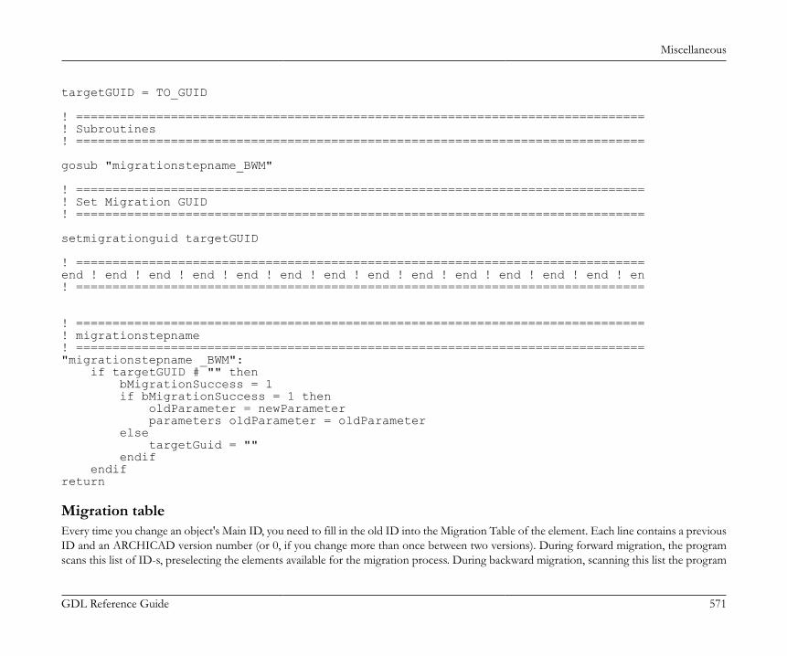
Miscellaneous
GDL Reference Guide 571
targetGUID = TO_GUID
! ==============================================================================! Subroutines! ==============================================================================
gosub "migrationstepname_BWM"
! ==============================================================================! Set Migration GUID! ==============================================================================
setmigrationguid targetGUID
! ==============================================================================end ! end ! end ! end ! end ! end ! end ! end ! end ! end ! end ! end ! end ! en! ==============================================================================
! ==============================================================================! migrationstepname! =============================================================================="migrationstepname _BWM": if targetGUID # "" then bMigrationSuccess = 1 if bMigrationSuccess = 1 then oldParameter = newParameter parameters oldParameter = oldParameter else targetGuid = "" endif endifreturn
Migration tableEvery time you change an object's Main ID, you need to fill in the old ID into the Migration Table of the element. Each line contains a previousID and an ARCHICAD version number (or 0, if you change more than once between two versions). During forward migration, the programscans this list of ID-s, preselecting the elements available for the migration process. During backward migration, scanning this list the program

Miscellaneous
GDL Reference Guide 572
chooses only those with a version equivalent to the previous ARCHICAD version. Every line of this table must have at least one correspondingsubroutine in the Forward Migration script and the Backward Migration script.
Writing macrosTry to collect frequently used functionalities into macros. Calling a macro object from many objects can reduce library size and increasesoundness by reducing redundancy.However avoid creating macros with small functional addition to the previous abstraction level. For example don't create a block_1x1x1 macrofor the generation of a 1m x 1m x 1m block. This increases the number of macro calls needlessly and it may worsen transparency.Don't ever use .gdl as macros, use macro objects instead.When you call a macro, always use the call keyword and put the name of the macro between quotation marks (e.g., call"m_rail_wired"). Do not create macro calls where the macro name is a parameter to avoid missing macros from archive files. ARCHICADsaves the default macro only into the archive file. (Workaround: call all parameter values as a macro after the end statement.)Be careful at using the parameter buffer. Save the content of it at be beginning of the script if you want to use it. Be sure that only the defined(return) values are in the buffer by the end of the script.
Macro return parametersFrom ARCHICAD 10 on macros can return parameters to the caller object. At the caller's side, returned values can be collected using thereturned_parameters keyword followed by a variable list. The returned values will be stored in these variables in the order they arereturned in the called macro. The number and the type of the variables specified in the caller and those returned in the macro must not match. Ifthere are more variables specified in the caller, they will be set to 0 integer. Type compatibility is not checked: the type of the variables specifiedin the caller will be set to the type of the returned values. If one of the variables in the caller is a dynamic array, all next values will be stored in it.In the macro object the end and the exit commands define the values that have to be return to the caller object. See the example below.
Advanced parameters allFrom ARCHICAD 10 on after parameters all keyword you can specify extra parameters to pass it to the macro. They will override thevalues coming from the caller or parameters of the called macro left to be default. The macro can return parameters in this case also.
Faster macro callSpeed of parameter value transferring between the caller object and the macro was improved in ARCHICAD 10. Find out tips about utilizationof macro call's speed enhancements in the section called “Speed Issues”.
Miscellaneous
GDL Reference Guide 573
Macro call exampleScript in the caller object.
call "myMacro" parameters all extraParam = 1call "myMacro" parameters returned_parameters realWidthcall "myMacro" parameters all extraParam = 1 returned_parameters realWidthcall "myMacro" parameters all returned_parameters realWidth Script in the macro.
realWidth = 2end realWidth
Background Conversion IssuesStarting from ARCHICAD 19, all calculations necessary for opening 3D related views or viewpoints will be run as background processes.Supported viewpoints:• 3D Window• Section• Elevation• Interior elevation (except when "Add bounded area" or "Detect and Fit to Zones" are enabled)• 3D DocumentIf the background process is successful, the requested view takes only a few seconds to open. However, there may be some non thread-safelibrary parts or objects placed in the planfile, which can disable background calculations:• Zones• Objects including text engine operations (except set style and define style commands)• Objects using the following requests: "CUSTOM_AUTO_LABEL", "ZONE_COLUS_AREA", "MATCHING_PROPERTIES",
"ASSOCEL_PROPERTIES", "STYLE_INFO", "TEXTBLOCK_INFO", "FONTNAMES_LIST"• Objects using variable named macros, requests, or non-thread safe macros. Project2 command or symbol fill definition are counted as non-
thread safe macro calls.The relationship between GDL add-ons and background processing depends on the add-on itself.Deterministic add-ons (not affecting background processing):

Miscellaneous
GDL Reference Guide 574
• Polygon Operations• Property Add-on• If used in read-only mode, and with files loaded in the active library: Text or Data I/O Add-ons, XML Add-onNon-deterministic add-ons (disabling background processing):• DateTime Add-on• FileManager Add-on• If not used in read-only mode, or not with files loaded in the active library: Text or Data I/O Add-ons, XML Add-onThe object scripts are examined statically, so the background conversion is disabled even if the obstacle function itself is not executed withthe current settings of the library part.To check the loaded library parts' compatibility with background processing, use the "Check if Library Parts are Thread Safe" command ofthe Library Developer menu.
Speed IssuesTry to avoid using the project2 command as it slows down plan regeneration.Reduce the number of surfaces in your model to the minimum in order to make 3D regeneration faster. Use RESOL, TOLER and RADIUScommands to control segmentation of curved surfaces.Note that closed bodies regenerate faster in 3D than open ones (e.g., a cylinder is faster than an open tube).When scripting the master script consider that the master script is run before each script type, so don't put script-type specific calculations here.This is the place for common calculations needed by multiple scripts.When scripting doors and windows avoid making unnecessary cuts (wallhole and wallniche).Use integer values and operations whenever reasonable, these are much faster than floating point operations.Try to minimize the usage of string operations.In case of calling macros use the same parameter order after the call command as it is in the parameter list of the macro. call "myMacro"parameters all is faster when the parameter orders of the macro and the caller object are similar. Try to avoid transferring string typeparameters in macro calls. Use numeric types where possible.
Windows-Macintosh compatibilityThough GDL objects and libraries are considered by GRAPHISOFT as platform independent, the following difficulties occur when objectsare manually moved from Windows to a Macintosh:• Windows fonts will be replaced by the default Macintosh font in objects and list templates and vice-versa.
Miscellaneous
GDL Reference Guide 575
• Text type listing files (listset.txt, listkey.txt, list templates, etc.) could lose line breaks, therefore listing won't work (non-utf-8 coded texts,usually)
Changing platform with binary librariesTo avoid the above problems, save a .pla archive file of your library on the first platform, then extract it on the second. This way the non-utf-8 files will be converted correctly as well.
Images and HDPI support in GDLStarting from ARCHICAD 21 real HDPI support is available for OS X devices. To provide this feature, scalable vector graphics (.svg) sourceimages are used to create multi-representation .tiff images, containing versions of the same graphic at different resolutions. ARCHICAD decidesat runtime which image resolution is the best for the current display device from the available set of 100%, 150%, and 200%. On Windowsplatform 100% is the default resolution. However, images created from .svg files have a slightly different look on Windows plaform as well.This option is only available via the LP_XMLConverter tool. The .svg source image files are automatically converted to .tiff images duringlibrary conversion. A .gsm object cannot handle .svg images, so make sure the image name reference strings in scripts contain the .tiff extension(or omit the extension).Always test vector images in all resolutions (the .tiff images can be checked by any image editor, resolution-by-resolution) to avoid blurry imagesafter scaling (use lines aligned to full pixels in the source .svg as much as possible. Same recommendation as for .png images.)The syntax requirements of any .svg built-in image (where the image is compiled into the binary library part itself) in GDLPict, Picture,InfoPict .xml sections are the following:• MIME attribute is "image/svg". In case the MIME-type and the source image extension is different, the conversion ends with a warning
(MIME is "image/svg", but the image file's extension is not svg)• SectionFlags attribute is "1". This flag triggers the .tiff conversion. If the image is an .svg and the flag is different, a warning is displayed
during conversion (SectionFlags should be "1" in case of an svg image).The rest of the image reference in GDLPict, Picture, InfoPict .xml sections have not changed. Make sure to get the extension of the sourceimage right in the path.Non-built-in images, which are directly referred by their name in the object scripts are handled by the LP_XMLConverter tool as well:• The .svg image should be part of the library source, but not in the _images folder.• The conversion creates the .tiff counterparts of the .svg source images to the exact same location. The .svg source images are also copied to
the binary library to a separate folder (_svg_source name extension), to support the source.xml to .gsm to reverse.xml comparison workflow.This extra folder can be avoided by the -excludesvg option of the LP_XMLConverter tool.
Any kind of .svg to .tiff conversion failure results in a warning or an error during library builds.
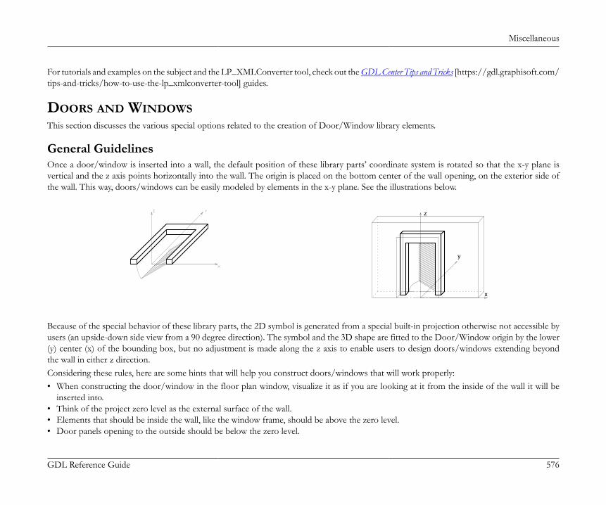
Miscellaneous
GDL Reference Guide 576
For tutorials and examples on the subject and the LP_XMLConverter tool, check out the GDL Center Tips and Tricks [https://gdl.graphisoft.com/tips-and-tricks/how-to-use-the-lp_xmlconverter-tool] guides.
DOORS AND WINDOWSThis section discusses the various special options related to the creation of Door/Window library elements.
General GuidelinesOnce a door/window is inserted into a wall, the default position of these library parts’ coordinate system is rotated so that the x-y plane isvertical and the z axis points horizontally into the wall. The origin is placed on the bottom center of the wall opening, on the exterior side ofthe wall. This way, doors/windows can be easily modeled by elements in the x-y plane. See the illustrations below.
x
y
z
Because of the special behavior of these library parts, the 2D symbol is generated from a special built-in projection otherwise not accessible byusers (an upside-down side view from a 90 degree direction). The symbol and the 3D shape are fitted to the Door/Window origin by the lower(y) center (x) of the bounding box, but no adjustment is made along the z axis to enable users to design doors/windows extending beyondthe wall in either z direction.Considering these rules, here are some hints that will help you construct doors/windows that will work properly:• When constructing the door/window in the floor plan window, visualize it as if you are looking at it from the inside of the wall it will be
inserted into.• Think of the project zero level as the external surface of the wall.• Elements that should be inside the wall, like the window frame, should be above the zero level.• Door panels opening to the outside should be below the zero level.
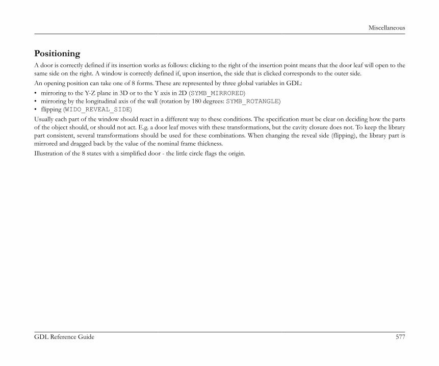
Miscellaneous
GDL Reference Guide 577
PositioningA door is correctly defined if its insertion works as follows: clicking to the right of the insertion point means that the door leaf will open to thesame side on the right. A window is correctly defined if, upon insertion, the side that is clicked corresponds to the outer side.An opening position can take one of 8 forms. These are represented by three global variables in GDL:• mirroring to the Y-Z plane in 3D or to the Y axis in 2D (SYMB_MIRRORED)• mirroring by the longitudinal axis of the wall (rotation by 180 degrees: SYMB_ROTANGLE)• flipping (WIDO_REVEAL_SIDE)Usually each part of the window should react in a different way to these conditions. The specification must be clear on deciding how the partsof the object should, or should not act. E.g. a door leaf moves with these transformations, but the cavity closure does not. To keep the librarypart consistent, several transformations should be used for these combinations. When changing the reveal side (flipping), the library part ismirrored and dragged back by the value of the nominal frame thickness.Illustration of the 8 states with a simplified door - the little circle flags the origin.
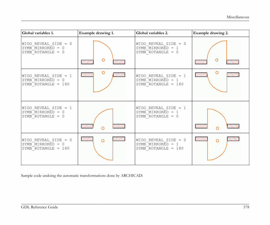
Miscellaneous
GDL Reference Guide 578
Global variables 1. Example drawing 1. Global variables 2. Example drawing 2.
WIDO_REVEAL_SIDE = 0SYMB_MIRRORED = 0SYMB_ROTANGLE = 0
WIDO_REVEAL_SIDE = 0SYMB_MIRRORED = 1SYMB_ROTANGLE = 0
WIDO_REVEAL_SIDE = 1SYMB_MIRRORED = 0SYMB_ROTANGLE = 180
WIDO_REVEAL_SIDE = 1SYMB_MIRRORED = 1SYMB_ROTANGLE = 180
WIDO_REVEAL_SIDE = 1SYMB_MIRRORED = 0SYMB_ROTANGLE = 0
WIDO_REVEAL_SIDE = 1SYMB_MIRRORED = 1SYMB_ROTANGLE = 0
WIDO_REVEAL_SIDE = 0SYMB_MIRRORED = 0SYMB_ROTANGLE = 180
WIDO_REVEAL_SIDE = 0SYMB_MIRRORED = 1SYMB_ROTANGLE = 180
Sample code undoing the automatic transformations done by ARCHICAD:
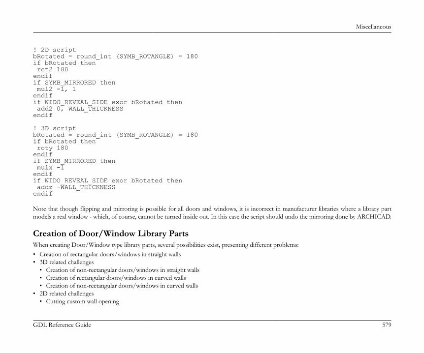
Miscellaneous
GDL Reference Guide 579
! 2D scriptbRotated = round_int (SYMB_ROTANGLE) = 180if bRotated then rot2 180endifif SYMB_MIRRORED then mul2 -1, 1endifif WIDO_REVEAL_SIDE exor bRotated then add2 0, WALL_THICKNESSendif
! 3D scriptbRotated = round_int (SYMB_ROTANGLE) = 180if bRotated then roty 180endifif SYMB_MIRRORED then mulx -1endifif WIDO_REVEAL_SIDE exor bRotated then addz -WALL_THICKNESSendif Note that though flipping and mirroring is possible for all doors and windows, it is incorrect in manufacturer libraries where a library partmodels a real window - which, of course, cannot be turned inside out. In this case the script should undo the mirroring done by ARCHICAD.
Creation of Door/Window Library PartsWhen creating Door/Window type library parts, several possibilities exist, presenting different problems:• Creation of rectangular doors/windows in straight walls• 3D related challenges
• Creation of non-rectangular doors/windows in straight walls• Creation of rectangular doors/windows in curved walls• Creation of non-rectangular doors/windows in curved walls
• 2D related challenges• Cutting custom wall opening

Miscellaneous
GDL Reference Guide 580
• WALLHOLE2• Extending the wall polygon• WALLBLOCK2• WALLLINE2• WALLARC2
Rectangular Doors/Windows in Straight WallsThis is the easiest and most straightforward way of creating doors and windows. The use of simple GDL commands such as PRISM_ or RECTis recommended.If you want to match the surface materials of door/window elements to those of the wall, the bottom surface of the elements should matchthe outside, and the top surface the inside of the wall. You can achieve this from your scripts using the WALL_MAT_A, WALL_MAT_B andWALL_MAT_EDGE global variables representing the surface materials of the wall into which the door/window is placed. In the 2D script,the WALL_SECT_PEN, WALL_FILL_PEN and WALL_FILL global variables can be useful, as these give you the pen numbers of the wallcontour and fill plus the index number of the fill of the wall on the floor plan into which the door/window is placed. With composite walls,you have to use the corresponding global variables.See Miscellaneous for details.The object libraries come with a large set of door/window macros. These GDL scripts contain common building elements which are used bymany doors/windows in the library. There are macros for generating commonly-used frames, panels and many other types of door/windowparts. Open some door/window library parts to see what kind of macros they call and what type of parts those macros generate.
Example:
X
Y
Z

Miscellaneous
GDL Reference Guide 581
a=0.9: b=1.5: c=0.1: d=0.08e=0.08: f=0.9: g=0.03: h=3PRISM_ 10, c, -a/2, 0, 15, a/2, 0, 15, a/2, b, 15, -a/2, b, 15, -a/2, 0, -1, -a/2+d, d, 15, a/2-d, d, 15, a/2-d, b-d, 15, -a/2+d, b-d, 15, -a/2+d, d, -1ADD -a/2+d, f, 0BRICK a-2*d, e, cADD -g/2, -f+d, c/2GOSUB 1ADDZ -gGOSUB 1DEL 2MATERIAL "Glass - Blue"ADD 0, -f+d, c/2RECT a-2*d, f-dADDY f-d+eRECT a-2*d, b-f-e-dEND
1: FOR i=1 TO h-1 ADDX (a-2*d)/3 BLOCK g, f-d, g ADDY f+e-d BLOCK g, b-f-d-e, g DEL 1 NEXT i DEL h-1 RETURN
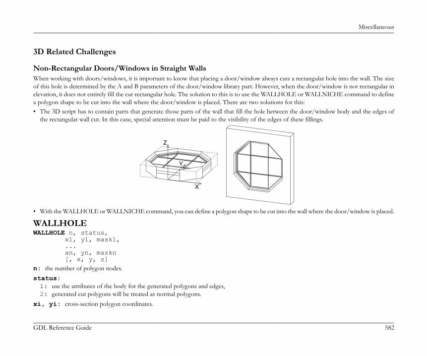
Miscellaneous
GDL Reference Guide 582
3D Related Challenges
Non-Rectangular Doors/Windows in Straight WallsWhen working with doors/windows, it is important to know that placing a door/window always cuts a rectangular hole into the wall. The sizeof this hole is determined by the A and B parameters of the door/window library part. However, when the door/window is not rectangular inelevation, it does not entirely fill the cut rectangular hole. The solution to this is to use the WALLHOLE or WALLNICHE command to definea polygon shape to be cut into the wall where the door/window is placed. There are two solutions for this:• The 3D script has to contain parts that generate those parts of the wall that fill the hole between the door/window body and the edges of
the rectangular wall cut. In this case, special attention must be paid to the visibility of the edges of these fillings.
X
Y
Z
• With the WALLHOLE or WALLNICHE command, you can define a polygon shape to be cut into the wall where the door/window is placed.
WALLHOLEWALLHOLE n, status, x1, y1, mask1, ... xn, yn, maskn [, x, y, z]n: the number of polygon nodes.status:1: use the attributes of the body for the generated polygons and edges,2: generated cut polygons will be treated as normal polygons.
xi, yi: cross-section polygon coordinates.

Miscellaneous
GDL Reference Guide 583
maski: similar to the CUTPOLYA command:maski = j1 + 2*j2 + 4*j3 + 64*j7, where each j can be 0 or 1.
x, y, z: optional direction vector (default is door/window Z axis).
x
z
y
1
n
i
i+1j1
j2
j3Z
Y
X
This command can be used in doors’/windows’ 3D script to cut custom hole(s) in the wall they are placed into. During the 3D generation ofthe current wall, the 3D script of all its doors/windows is interpreted without model generation to collect the WALLHOLE commands. If theyexist, the current wall will be cut using an infinite tube with the polygonal cross-section and direction defined in the script. There can be anynumber of WALLHOLEs for any door/window, so it is possible to cut more holes for the same door/window, even intersecting ones. If atleast one WALLHOLE command is interpreted in a door/window 3D script, no rectangular opening will be generated for that door/window.
Note: The 3D reveal will not be generated automatically for custom holes, you have to generate it from the script. The hole customized thisway will only be visible in 3D, because WALLHOLE commands do not have any effect in 2D. A 2D representation can be scripted if needed(used with framing in plan off).
The use of convex polygonal cross-sections is recommended; using concave polygons may result in strange shadings/renderings or cut errors.Convex polygons can be combined to obtain concave ones. Mirroring transformations affect the cutting direction in an unexpected way - toget a more straightforward result, use the WALLNICHE command.
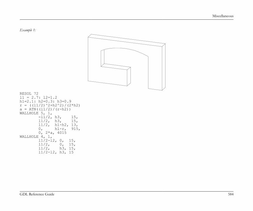
Miscellaneous
GDL Reference Guide 584
Example 1:
RESOL 72l1 = 2.7: l2=1.2h1=2.1: h2=0.3: h3=0.9r = ((l1/2)^2+h2^2)/(2*h2)a = ATN((l1/2)/(r-h2))WALLHOLE 5, 1, -l1/2, h3, 15, l1/2, h3, 15, l1/2, h1-h2, 13, 0, h1-r, 915, 0, 2*a, 4015WALLHOLE 4, 1, l1/2-l2, 0, 15, l1/2, 0, 15, l1/2, h3, 15, l1/2-l2, h3, 15
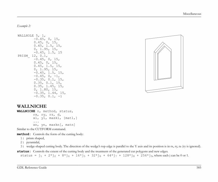
Miscellaneous
GDL Reference Guide 585
Example 2:
WALLHOLE 5, 1, -0.45, 0, 15, 0.45, 0, 15, 0.45, 1.5, 15, 0, 1.95, 15, -0.45, 1.5, 15PRISM_ 12, 0.1, -0.45, 0, 15, 0.45, 0, 15, 0.45, 1.5, 15, 0, 1.95, 15, -0.45, 1.5, 15, -0.45, 0, -1, -0.35, 0.1, 15, 0.35, 0.1, 15, 0.35, 1.45, 15, 0, 1.80, 15, -0.35, 1.44, 15, -0.35, 0.1, -1
WALLNICHEWALLNICHE n, method, status, rx, ry, rz, d, x1, y1, mask1, [mat1,] ... xn, yn, maskn[, matn]Similar to the CUTFORM command.method: Controls the form of the cutting body:1: prism shaped,2: pyramidal,3: wedge-shaped cutting body. The direction of the wedge’s top edge is parallel to the Y axis and its position is in rx, ry, rz (ry is ignored).
status: Controls the extent of the cutting body and the treatment of the generated cut polygons and new edges.status = j1 + 2*j2 + 8*j4 + 16*j5 + 32*j6 + 64*j7 + 128*j8 + 256*j9, where each j can be 0 or 1.
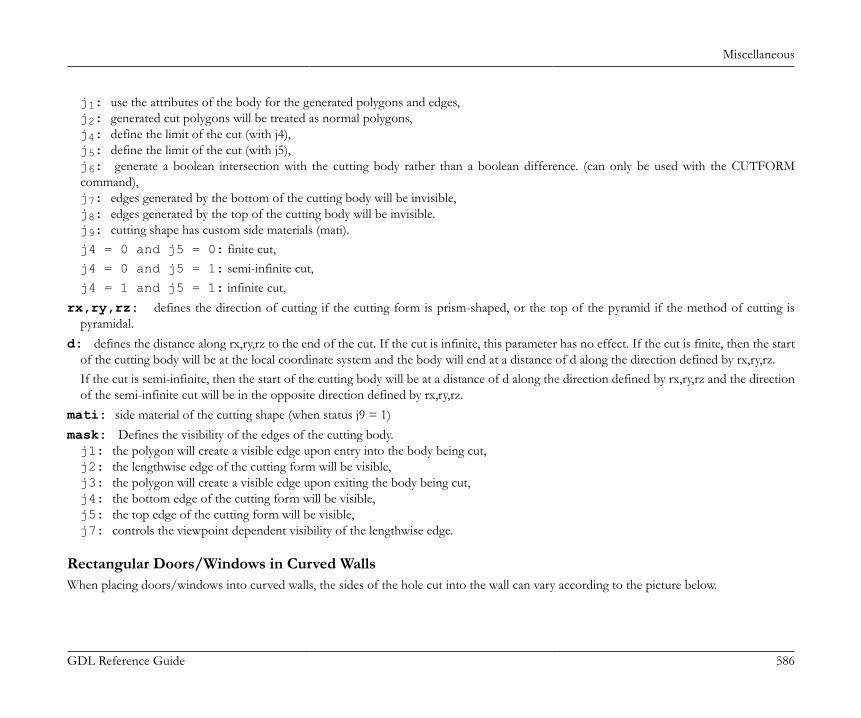
Miscellaneous
GDL Reference Guide 586
j1: use the attributes of the body for the generated polygons and edges,j2: generated cut polygons will be treated as normal polygons,j4: define the limit of the cut (with j4),j5: define the limit of the cut (with j5),j6: generate a boolean intersection with the cutting body rather than a boolean difference. (can only be used with the CUTFORMcommand),j7: edges generated by the bottom of the cutting body will be invisible,j8: edges generated by the top of the cutting body will be invisible.j9: cutting shape has custom side materials (mati).j4 = 0 and j5 = 0: finite cut,j4 = 0 and j5 = 1: semi-infinite cut,j4 = 1 and j5 = 1: infinite cut,
rx,ry,rz: defines the direction of cutting if the cutting form is prism-shaped, or the top of the pyramid if the method of cutting ispyramidal.
d: defines the distance along rx,ry,rz to the end of the cut. If the cut is infinite, this parameter has no effect. If the cut is finite, then the startof the cutting body will be at the local coordinate system and the body will end at a distance of d along the direction defined by rx,ry,rz.If the cut is semi-infinite, then the start of the cutting body will be at a distance of d along the direction defined by rx,ry,rz and the directionof the semi-infinite cut will be in the opposite direction defined by rx,ry,rz.
mati: side material of the cutting shape (when status j9 = 1)mask: Defines the visibility of the edges of the cutting body.j1: the polygon will create a visible edge upon entry into the body being cut,j2: the lengthwise edge of the cutting form will be visible,j3: the polygon will create a visible edge upon exiting the body being cut,j4: the bottom edge of the cutting form will be visible,j5: the top edge of the cutting form will be visible,j7: controls the viewpoint dependent visibility of the lengthwise edge.
Rectangular Doors/Windows in Curved WallsWhen placing doors/windows into curved walls, the sides of the hole cut into the wall can vary according to the picture below.
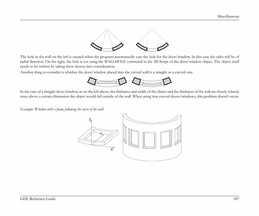
Miscellaneous
GDL Reference Guide 587
The hole in the wall on the left is created when the program automatically cuts the hole for the door/window. In this case the sides will be ofradial direction. On the right, the hole is cut using the WALLHOLE command in the 3D Script of the door/window object. The object itselfneeds to be written by taking these factors into consideration.Another thing to consider is whether the door/window placed into the curved wall is a straight or a curved one.
In the case of a straight door/window, as on the left above, the thickness and width of the object and the thickness of the wall are closely related,since above a certain dimension the object would fall outside of the wall. When using true curved doors/windows, this problem doesn’t occur.
Example: Window with a frame following the curve of the wall
Y
X
Z

Miscellaneous
GDL Reference Guide 588
RESOL 72ROTX -90 : MULY -1C= 0.12 : Z=360*A/(2*WIDO_ORIG_DIST*PI)Y= 360*C/(2*WIDO_ORIG_DIST*PI) : A1= 270+Z/2 : A2=270-Z/2GOSUB "curved_horizontal_frame"ADDZ BMULZ -1GOSUB "curved_horizontal_frame"DEL 2ADDZ CGOSUB "vertical_frame"MULX -1GOSUB "vertical_frame"END"curved_horizontal_frame": PRISM_ 9, C, cos(A2)*R_, SIN(A2)*R_+R_, 11, cos(A2+Y)*R_, sin(A2+Y)*R_+R_, 13, 0, R_, 900, 0, Z-2*Y, 4009, cos(A1)*R_, sin(A1)*R_+R_, 11, cos(A1)*(R_-0.1), sin(A1)*(R_-0.1)+R_, 11, cos(A1-Y)*(R_-0.1), sin(A1-Y)*(R_-0.1)+R_, 13, 0, -(Z-2*Y), 4009, cos(A2)*(R_-0.1), sin(A2)*(R_-0.1)+R_, 11 RETURN"vertical_frame": PRISM_ 4, B-2*C, cos(A2)*R_, sin(A2)*R_+R_, 10, cos(A2+Y)*R_, sin(A2+Y)*R_+R_, 15, cos(A2+Y)*(R_-0.1), sin(A2+Y)*(R_-0.1)+R_, 10, cos(A2)*(R_-0.1), sin(A2)*(R_-0.1)+R_, 10 RETURN
Non-Rectangular Doors/Windows in Curved WallsThe general guidelines given for rectangular doors/windows in curved walls applies here, too.
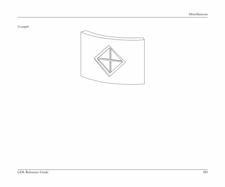
Miscellaneous
GDL Reference Guide 589
Example:
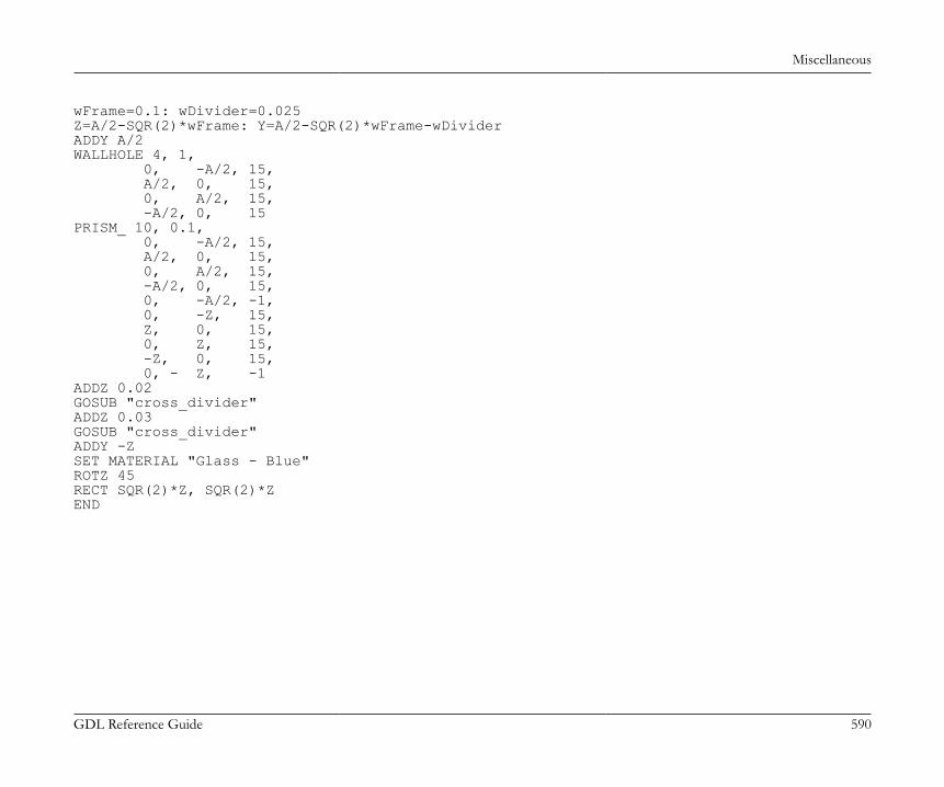
Miscellaneous
GDL Reference Guide 590
wFrame=0.1: wDivider=0.025Z=A/2-SQR(2)*wFrame: Y=A/2-SQR(2)*wFrame-wDividerADDY A/2WALLHOLE 4, 1, 0, -A/2, 15, A/2, 0, 15, 0, A/2, 15, -A/2, 0, 15PRISM_ 10, 0.1, 0, -A/2, 15, A/2, 0, 15, 0, A/2, 15, -A/2, 0, 15, 0, -A/2, -1, 0, -Z, 15, Z, 0, 15, 0, Z, 15, -Z, 0, 15, 0, - Z, -1ADDZ 0.02GOSUB "cross_divider"ADDZ 0.03GOSUB "cross_divider"ADDY -ZSET MATERIAL "Glass - Blue"ROTZ 45RECT SQR(2)*Z, SQR(2)*ZEND
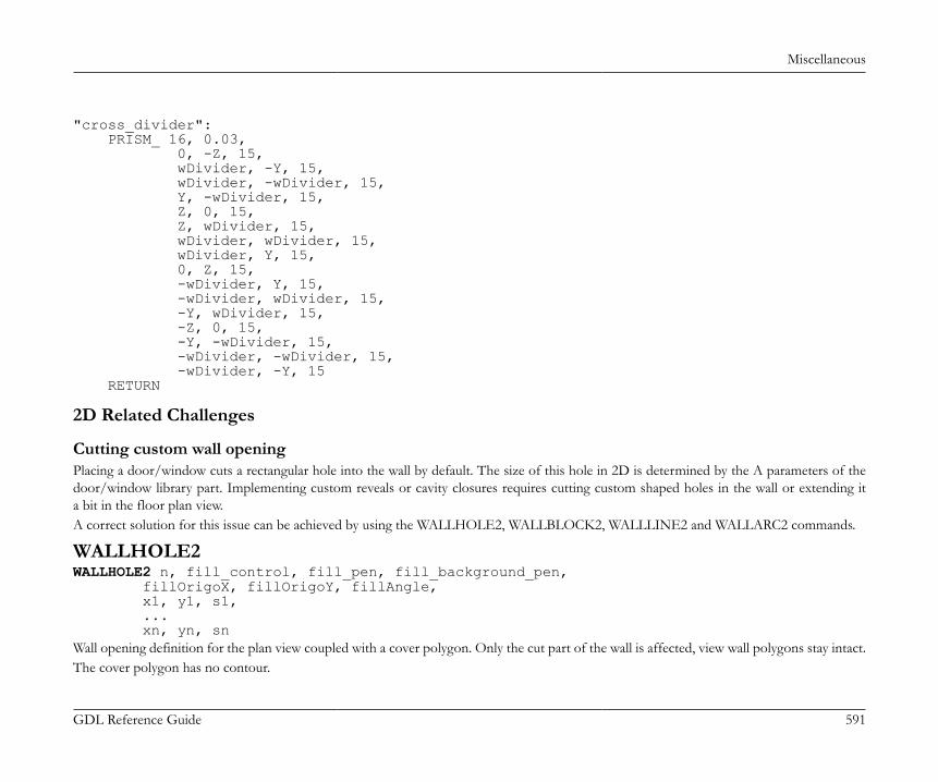
Miscellaneous
GDL Reference Guide 591
"cross_divider": PRISM_ 16, 0.03, 0, -Z, 15, wDivider, -Y, 15, wDivider, -wDivider, 15, Y, -wDivider, 15, Z, 0, 15, Z, wDivider, 15, wDivider, wDivider, 15, wDivider, Y, 15, 0, Z, 15, -wDivider, Y, 15, -wDivider, wDivider, 15, -Y, wDivider, 15, -Z, 0, 15, -Y, -wDivider, 15, -wDivider, -wDivider, 15, -wDivider, -Y, 15 RETURN
2D Related Challenges
Cutting custom wall openingPlacing a door/window cuts a rectangular hole into the wall by default. The size of this hole in 2D is determined by the A parameters of thedoor/window library part. Implementing custom reveals or cavity closures requires cutting custom shaped holes in the wall or extending ita bit in the floor plan view.A correct solution for this issue can be achieved by using the WALLHOLE2, WALLBLOCK2, WALLLINE2 and WALLARC2 commands.
WALLHOLE2WALLHOLE2 n, fill_control, fill_pen, fill_background_pen, fillOrigoX, fillOrigoY, fillAngle, x1, y1, s1, ... xn, yn, snWall opening definition for the plan view coupled with a cover polygon. Only the cut part of the wall is affected, view wall polygons stay intact.The cover polygon has no contour.
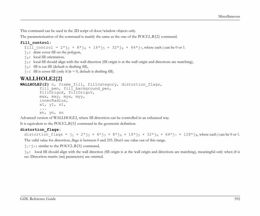
Miscellaneous
GDL Reference Guide 592
This command can be used in the 2D script of door/window objects only.The parameterization of the command is mainly the same as the one of the POLY2_B{2} command.fill_control:fill_control = 2*j2 + 8*j4 + 16*j5 + 32*j6 + 64*j7, where each j can be 0 or 1.j2: draw cover fill on the polygon,j4: local fill orientation,j5: local fill should align with the wall direction (fill origin is at the wall origin and directions are matching),j6: fill is cut fill (default is drafting fill),j7: fill is cover fill (only if j6 = 0, default is drafting fill).
WALLHOLE2{2}WALLHOLE2{2} n, frame_fill, fillcategory, distortion_flags, fill_pen, fill_background_pen, fillOrigoX, fillOrigoY, mxx, mxy, myx, myy, innerRadius, x1, y1, s1, ... xn, yn, snAdvanced version of WALLHOLE2, where fill distortion can be controlled in an enhanced way.It is equivalent to the POLY2_B{5} command in the geometric definition.distortion_flags:distortion_flags = j1 + 2*j2 + 4*j3 + 8*j4 + 16*j5 + 32*j6 + 64*j7 + 128*j8, where each j can be 0 or 1.The valid value for distortion_flags is between 0 and 255. Don’t use value out of this range.j1-j7: similar to the POLY2_B{5} command,j8: local fill should align with the wall direction (fill origin is at the wall origin and directions are matching), meaningful only when j4 isset. Distortion matrix (mij parameters) are omitted.
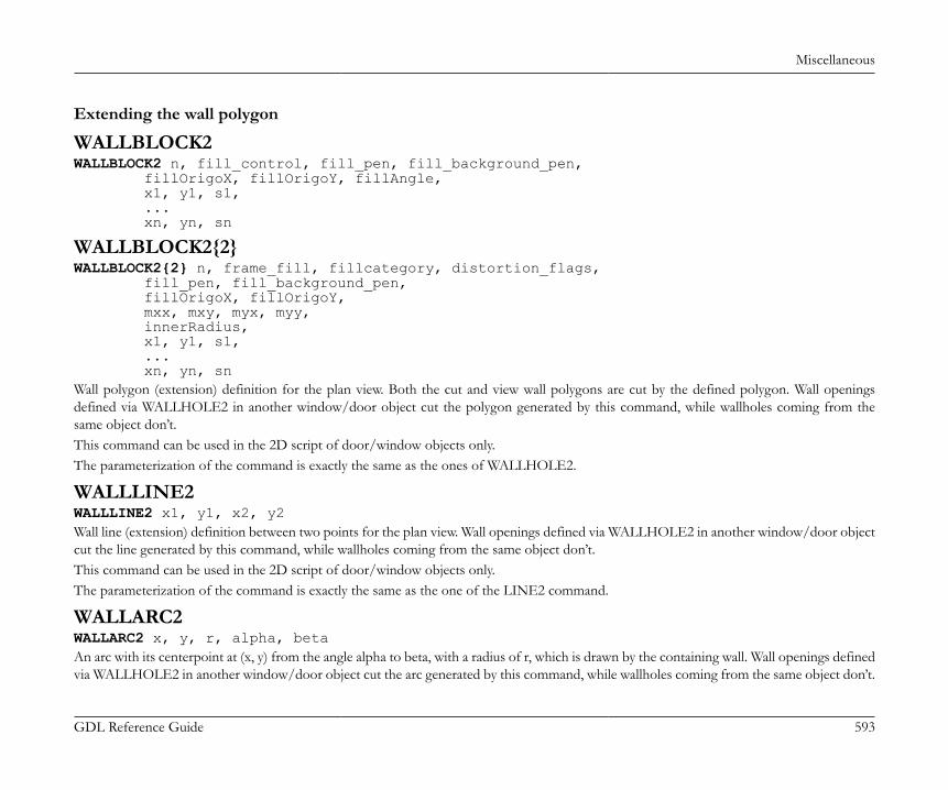
Miscellaneous
GDL Reference Guide 593
Extending the wall polygon
WALLBLOCK2WALLBLOCK2 n, fill_control, fill_pen, fill_background_pen, fillOrigoX, fillOrigoY, fillAngle, x1, y1, s1, ... xn, yn, sn
WALLBLOCK2{2}WALLBLOCK2{2} n, frame_fill, fillcategory, distortion_flags, fill_pen, fill_background_pen, fillOrigoX, fillOrigoY, mxx, mxy, myx, myy, innerRadius, x1, y1, s1, ... xn, yn, snWall polygon (extension) definition for the plan view. Both the cut and view wall polygons are cut by the defined polygon. Wall openingsdefined via WALLHOLE2 in another window/door object cut the polygon generated by this command, while wallholes coming from thesame object don’t.This command can be used in the 2D script of door/window objects only.The parameterization of the command is exactly the same as the ones of WALLHOLE2.
WALLLINE2WALLLINE2 x1, y1, x2, y2Wall line (extension) definition between two points for the plan view. Wall openings defined via WALLHOLE2 in another window/door objectcut the line generated by this command, while wallholes coming from the same object don’t.This command can be used in the 2D script of door/window objects only.The parameterization of the command is exactly the same as the one of the LINE2 command.
WALLARC2WALLARC2 x, y, r, alpha, betaAn arc with its centerpoint at (x, y) from the angle alpha to beta, with a radius of r, which is drawn by the containing wall. Wall openings definedvia WALLHOLE2 in another window/door object cut the arc generated by this command, while wallholes coming from the same object don’t.

Miscellaneous
GDL Reference Guide 594
This command can be used in the 2D script of door/window objects only.The parameterization of the command is exactly the same as the one of the ARC2 command.
GDL CREATED FROM THE FLOOR PLANSaving the floor plan as a GDL script or library part will result GDL elements. You can use these GDL scripts as templates for your customlibrary parts.
KEYWORDS
Common KeywordsFILE_DEPENDENCEMODANDOREXORFORTOSTEPNEXTDO (at DO - WHILE, at WHILE - ENDWHILE)WHILE (at DO - WHILE, at WHILE - ENDWHILE)ENDWHILEREPEATUNTILIF (at IF - GOTO, at IF - THEN - ELSE - ENDIF)THEN (at IF - GOTO, at IF - THEN - ELSE - ENDIF)GOTO (at IF - GOTO, at GOTO)GOSUB (at IF - GOTO, at GOSUB)ELSEENDIFRETURN

Miscellaneous
GDL Reference Guide 595
ENDEXITBREAKPOINT
FILLTYPES_MASK (at DEFINE FILL, at DEFINE FILLA, at DEFINE SYMBOL_FILL, at DEFINESOLID_FILL, at DEFINE EMPTY_FILL, at DEFINE LINEAR_GRADIENT_FILL, at DEFINERADIAL_GRADIENT_FILL, at DEFINE TRANSLUCENT_FILL, at DEFINE IMAGE_FILL, at VALUES)PROFILETYPES_MASKDICTDIMPUTGETUSENSPCALLRETURNED_PARAMETERSDEFAULTPRINT
HASKEYREMOVEKEYVARDIM1VARDIM2PARVALUE_DESCRIPTIONABSCEILINTFRAROUND_INTSGNSQRACSASN

Miscellaneous
GDL Reference Guide 596
ATNCOSSINTANPIEXPLGTLOGNOTMINMAXRNDBITTESTBITSETREQREQUESTINDAPPLICATION_QUERYLIBRARYGLOBALSTRSTR{2}SPLITSTWSTRLENSTRSTRSTRSUBSTRTOUPPERSTRTOLOWEROPENINPUTVARTYPEOUTPUTCLOSE

Miscellaneous
GDL Reference Guide 597
INITADDONSCOPEPREPAREFUNCTIONCALLFUNCTIONCLOSEADDONSCOPE
Reserved KeywordsThe keywords listed below are reserved; they exist for compatibility reasons or are not publicized. BAS BOX CONT FILTER GDLBIN HIP_ROOFS LIN LINE MIGRATIONWARNING NOD NODE ORIGO PARS PAUSE PLOTMAKER PLOTTER RECT_ REF SFLINE TET TETRA TRI WALL_ VOCA UI_OK UI_CANCEL
3D Use OnlyADDX

Miscellaneous
GDL Reference Guide 598
ADDYADDZADDMULXMULYMULZMULROTXROTYROTZROTXFORM
BLOCKBRICKCYLINDSPHEREELLIPSCONEPRISMPRISM_CPRISM_CPRISM_{2}CPRISM_{3}CPRISM_{4}BPRISM_FPRISM_HPRISM_SPRISM_SPRISM_{2}SPRISM_{3}SPRISM_{4}SLAB

Miscellaneous
GDL Reference Guide 599
SLAB_CSLAB_CWALL_BWALL_XWALL_XWALL_{2}XWALL_{3}BEAMCROOF_CROOF_{2}CROOF_{3}CROOF_{4}MESHARMCARMEELBOWEXTRUDEPYRAMIDREVOLVEREVOLVE{2}REVOLVE{3}REVOLVE{4}REVOLVE{5}RULEDRULED{2}RULEDSEGMENTEDRULEDSEGMENTED{2}SWEEPTUBETUBE{2}TUBEACOONSCOONS{2}
Miscellaneous
GDL Reference Guide 600
MASSMASS{2}POLYROOFPOLYROOF{2}POLYROOF{3}POLYROOF{4}EXTRUDEDSHELLEXTRUDEDSHELL{2}EXTRUDEDSHELL{3}REVOLVEDSHELLREVOLVEDSHELL{2}REVOLVEDSHELL{3}REVOLVEDSHELLANGULARREVOLVEDSHELLANGULAR{2}REVOLVEDSHELLANGULAR{3}RULEDSHELLRULEDSHELL{2}RULEDSHELL{3}TEXTBODYBASENURBSCURVE2DNURBSCURVE3DNURBSSURFACENURBSVERTNURBSEDGENURBSTRIMNURBSTRIMSINGULARNURBSFACENURBSFACE{2}NURBSLUMPNURBSBODYPOINTCLOUD

Miscellaneous
GDL Reference Guide 601
CUTPLANECUTEND (at CUTPLANE, at CUTPLANE{2}, at CUTPLANE{3}, at CUTPOLY, at CUTPOLYA, at CUTSHAPE)CUTPLANE{2}CUTPLANE{3}CUTPOLYCUTPOLYACUTSHAPECUTFORMCUTFORM{2}GROUPENDGROUPADDGROUPADDGROUP{2}ADDGROUP{3}SUBGROUPSUBGROUP{2}SUBGROUP{3}ISECTGROUPISECTGROUP{2}ISECTGROUP{3}ISECTLINESPLACEGROUPKILLGROUPSWEEPGROUPSWEEPGROUP{2}SWEEPGROUP{3}SWEEPGROUP{4}SWEEPGROUP{5}CREATEGROUPWITHMATERIALBINARYWALLNICHE
HOTSPOT
Miscellaneous
GDL Reference Guide 602
HOTLINEHOTARCLIN_RECTPOLYPOLY_PLANEPLANE_CIRCLEARCLIGHTPICTURERICHTEXTVERT (at VERT, at VERT{2})TEVEVECTEDGEPGONPGON{2}PGON{3}PIPGCOORCOOR{2}COOR{3}MODELWIRESURFACESOLIDMATERIAL (at [SET] MATERIAL, at IND)BUILDING_MATERIAL (at [SET] BUILDING_MATERIAL, at IND)SECT_FILLSECT_ATTRSSECT_ATTRS{2}

Miscellaneous
GDL Reference Guide 603
SHADOWONOFFAUTODEFINE MATERIAL (at DEFINE MATERIAL, at DEFINE MATERIAL BASED_ON)BASED_ONDEFINE TEXTURETEXTUREWALLHOLE
2D Use OnlyADD2MUL2ROT2
LINE2RECT2POLY2POLY2_POLY2_APOLY2_BPOLY2_B{2}POLY2_B{3}POLY2_B{4}POLY2_B{5}POLY2_B{6}ARC2CIRCLE2SPLINE2SPLINE2ATEXT2RICHTEXT2FRAGMENT2
Miscellaneous
GDL Reference Guide 604
PROJECT2PROJECT2{2}PROJECT2{3}PROJECT2{4}DRAWING2DRAWING3DRAWING3{2}DRAWING3{3}WALLHOLE2WALLHOLE2{2}WALLBLOCK2WALLBLOCK2{2}WALLLINE2WALLARC2
HOTSPOT2HOTLINE2HOTARC2PICTURE2PICTURE2{2}LINE_PROPERTYDRAWINDEXFILL (at [SET] FILL, at IND)LINE_TYPE (at [SET] LINE_TYPE, at IND)DEFINE FILLDEFINE FILLADEFINE SYMBOL_FILLDEFINE SOLID_FILLDEFINE EMPTY_FILLDEFINE LINEAR_GRADIENT_FILLDEFINE RADIAL_GRADIENT_FILLDEFINE TRANSLUCENT_FILLDEFINE IMAGE_FILL
Miscellaneous
GDL Reference Guide 605
DEFINE LINE_TYPEDEFINE SYMBOL_LINE
2D and 3D UseDEL (at DEL, at DEL TOP)TOPNTRADDITIONAL_DATA (at LIGHT, at DEFINE MATERIAL BASED_ON)LETRADIUSRESOLTOLERPENSET (at [SET] STYLE, at [SET] MATERIAL, at [SET] BUILDING_MATERIAL, at [SET] FILL, at [SET]LINE_TYPE)STYLE (at [SET] STYLE, at IND)DEFINE STYLEDEFINE STYLE{2}PARAGRAPHENDPARAGRAPHTEXTBLOCKTEXTBLOCK_PROFILE_ATTR
Non-Geometric Scripts
Properties ScriptDATABASE_SETDESCRIPTORREF DESCRIPTORCOMPONENTREF COMPONENT
Miscellaneous
GDL Reference Guide 606
BINARYPROPSURFACE3DVOLUME3DPOSITIONWALLSCOLUMNSBEAMSDOORSWINDOWSOBJECTSCEILSPITCHED_ROOFSLIGHTSHATCHESROOMSMESHESDRAWING
Parameter ScriptVALUESCUSTOM (at VALUES, at UI_INFIELD{4})RANGEVALUES{2}PARAMETERS (at PARAMETERS, at CALL)LOCKALL (at LOCK, at HIDEPARAMETER, at CALL)HIDEPARAMETER
Interface ScriptUI_DIALOGUI_PAGEUI_CURRENT_PAGEUI_BUTTON (at UI_BUTTON, at UI_TOOLTIP)
Miscellaneous
GDL Reference Guide 607
UI_PREVUI_NEXTUI_FUNCTIONUI_LINKUI_PICT_BUTTON (at UI_PICT_BUTTON, at UI_TOOLTIP)UI_SEPARATORUI_GROUPBOXUI_PICT (at UI_PICT, at UI_TOOLTIP)UI_STYLEUI_OUTFIELD (at UI_OUTFIELD, at UI_TOOLTIP)UI_INFIELD (at UI_INFIELD, at UI_TOOLTIP)UI_INFIELD{2} (at UI_INFIELD{2}, at UI_TOOLTIP)UI_INFIELD{3} (at UI_INFIELD{3}, at UI_TOOLTIP)UI_INFIELD{4} (at UI_INFIELD{4}, at UI_TOOLTIP)UI_CUSTOM_POPUP_INFIELD (at UI_CUSTOM_POPUP_INFIELD, at UI_TOOLTIP)UI_CUSTOM_POPUP_INFIELD{2} (at UI_CUSTOM_POPUP_INFIELD{2}, at UI_TOOLTIP)UI_RADIOBUTTON (at UI_RADIOBUTTON, at UI_TOOLTIP)UI_RADIOBUTTON{2}UI_PICT_RADIOBUTTONUI_PICT_RADIOBUTTON{2}UI_PICT_PUSHCHECKBUTTONUI_PICT_PUSHCHECKBUTTON{2}UI_TEXTSTYLE_INFIELDUI_TEXTSTYLE_INFIELD{2}UI_LISTFIELD (at UI_LISTFIELD, at UI_TOOLTIP)UI_LISTITEM (at UI_LISTITEM, at UI_TOOLTIP)UI_LISTITEM{2} (at UI_LISTITEM{2}, at UI_TOOLTIP)UI_CUSTOM_POPUP_LISTITEM (at UI_CUSTOM_POPUP_LISTITEM, at UI_TOOLTIP)UI_CUSTOM_POPUP_LISTITEM{2} (at UI_CUSTOM_POPUP_LISTITEM{2}, at UI_TOOLTIP)UI_TOOLTIPUI_COLORPICKERUI_COLORPICKER{2}UI_SLIDER
Miscellaneous
GDL Reference Guide 608
UI_SLIDER{2}
Forward and Backward Migration ScriptsSETMIGRATIONGUIDSTORED_PAR_VALUEDELETED_PAR_VALUENEWPARAMETER
GDL DATA I/O ADD-ONThe GDL Data In/Out Add-On allows you to access a simple kind of database by using GDL commands. Otherwise this Add-On is similarto the GDL Text In/Out Add-On.
Description of DatabaseThe database is a text file in which the records are stored in separate lines. The database can be queried and modified based on a single key.The key and the other items are separated by a character (specified in the OPEN command).The length of the lines does not need to be the same and even the number of columns in the records may be different.If a database is open for writing then there should be enough space beside the database file for duplicating the whole file.Opening and closing a database may be time consuming, so consecutive closing and opening of a database should be avoided.Large databases (with more than some hundred thousand records) should be ordered by the key values.A database can be opened, queried, modified and closed by this Add-On using the OPEN, INPUT, OUTPUT and CLOSE GDL commands.
Opening a Databasechannel = OPEN (filter, filename, paramstring)Opens the database. If the database file is to be opened for modification and the file does not exist, it creates a new file. If the database file isto be opened for reading and the file does not exist, an error message is displayed.Its return value is a positive integer that will identify the specific database. This value will be the database’s future reference number.If the database is opened before open command, it will generate a channel number only.filter: the internal name of the Add-On, in this case "DATA"filename: the name of the database file to be openedparamstring: add-on specific parameter, contains separator characters and file opening mode parameters

Miscellaneous
GDL Reference Guide 609
The paramstring may contain the following:SEPARATOR: after the keyword between single quotation marks ('') you can define a character that you want to use in your text file (bothin case of writing and reading) for the separation of data fields. A special case is the tabulator character ('\t').MODE: after the keyword the mode of opening has to follow. There are three modes of opening:• RO (read only)• WA (read, append/modify)• WO (overwrite) Empties the database if exists.DIALOG: the 'filename' parameter is working as a file-identifier, otherwise it is a full-path-name. The file-identifier is a simple string, whichwill be matched to an existing file by the Add-On during a standard 'Open/Save as' dialog. This matching is stored by the Add-On and itwon't ask again except when the file is not available any more. If the open mode is read only, the Add-On will put up an Open dialog toselect an existing document. Otherwise the Add-On put up an alert-dialog to select between the 'Create' and 'Browse' options:• Create: create a new data-file (Save as Dialog).• Browse: search an existing data-file (Open dialog)LIBRARY: If the LIBRARY keyword is present in the parameter string, the data file has to be in the loaded library. Opening data file fromthe loaded library for reading is possible from all scripts, but writing is only enabled in the parameter, user interface and property scripts.Always put a comma (,) between the components of paramstring.If you use keywords that don’t exist, if the separator characters given are wrong or if there is nothing in the parameter string, the extensionwill use the default settings: "SEPARATOR = '\t', MODE = RO"
Example:ch1 = OPEN ("DATA", "file1", "SEPARATOR=';', MODE = RO, DIALOG")ch2 = OPEN ("DATA", "file2", "")ch3 = OPEN ("DATA", "newfile", "SEPARATOR = '\t', MODE = WA")
Reading Values from DatabaseINPUT (channel, recordID, fieldID, var1 [, var2, ...])Queries the database based on the key value.If it finds the record, it reads items from the record starting from the given column and puts the read values into the parameters in sequence.In the parameter list there has to be at least one value. The values can be of numeric or string type independently of the parameter type definedfor them. The return value is the number of successfully read values.
Miscellaneous
GDL Reference Guide 610
If there are more parameters than values, the parameters without corresponding values will be set to zero. In case of empty columns (i.e. ifthere is nothing between the separator characters) the parameters will be set to zero.If it finds no record it returns (-1).channel: channel value, used to identify the connection.recordID: key value (numeric or string).fieldID: the column number in the given record (the smallest number, 1 refers to the item after the key value).vari: variables to receive the read record items.
Example:! input of three values from the first column of the first rownr = INPUT (ch1, "key1", 1, v1, v2, v3)
PRINT nr, v1, v2, v3
Writing Values into DatabaseOUTPUT channel, recordID, fieldID, expr1 [, expr2, ...]In case of record creation or modification, it sets the record belonging to the given key value. The record will contain the given values in thesame sequence as they appear in the command. The values can be of numeric or string type. There has to be at least one expression.In case of deletion the record belonging to the given key value is removed from the database. The expression values are ignored, however atleast one should be specified.Modifying data files loaded with the library is only enabled in the parameter, user interface and property scripts.recordID: key value (numeric or string)fieldID: flag: specify 0 (or <= 0) to delete a record, specify 1 (or > 0) to create or modify a recordexpri: new item values of the found or new record. In case of deletion these values are ignored
Example:string = "Date: 19.01.1996"a = 1.5OUTPUT ch2, "keyA", 1, "New record"OUTPUT ch2, "keyA", 1, "Modified record"OUTPUT ch2, "keyA", 0, 0 ! deletes the recordOUTPUT ch2, "keyB", 1, a, string
Miscellaneous
GDL Reference Guide 611
Closing DatabaseCLOSE channelchannel: channel valueCloses the database identified by the channel value.
GDL DATETIME ADD-ONThe DateTime extension allows you to set various formats for the current date and time set on your computer.The Add-On works the same way the GDL file operations. You have to open a channel, read the information and close the channel.This Add-On is also available by using the REQUEST GDL command, in which case the sequence of commands OPEN, INPUT and CLOSEis called internally. This is the simplest way to obtain the date/time information, with just a single GDL command line:REQUEST ("DateTime", format_string, datetimestring)The second parameter of the Request function is the same as that described in the OPEN function paramstring parameter.
Opening Channelchannel = OPEN (filter, filename, paramstring)Its return value is a positive integer that will identify the opened channel. This value will become the channel’s future reference number. Theparamstring can contain specifiers and other characters.filter: the internal name of the Add-On, in this case "DateTime"filename: unused (there is no need to open any file to get the system date and time)paramstring: add-on specific parameter, contains the desired output format of the date and timeThe specifiers are replaced with date and time values as follows:
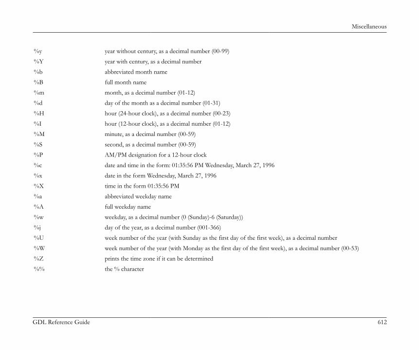
Miscellaneous
GDL Reference Guide 612
%y year without century, as a decimal number (00-99)
%Y year with century, as a decimal number
%b abbreviated month name
%B full month name
%m month, as a decimal number (01-12)
%d day of the month as a decimal number (01-31)
%H hour (24-hour clock), as a decimal number (00-23)
%I hour (12-hour clock), as a decimal number (01-12)
%M minute, as a decimal number (00-59)
%S second, as a decimal number (00-59)
%P AM/PM designation for a 12-hour clock
%c date and time in the form: 01:35:56 PM Wednesday, March 27, 1996
%x date in the form Wednesday, March 27, 1996
%X time in the form 01:35:56 PM
%a abbreviated weekday name
%A full weekday name
%w weekday, as a decimal number (0 (Sunday)-6 (Saturday))
%j day of the year, as a decimal number (001-366)
%U week number of the year (with Sunday as the first day of the first week), as a decimal number
%W week number of the year (with Monday as the first day of the first week), as a decimal number (00-53)
%Z prints the time zone if it can be determined
%% the % character

Miscellaneous
GDL Reference Guide 613
Example:dstr = ""ch = OPEN ("DateTime", "", "%w/%m/%d/%Y, %H:%M%P")n = INPUT (ch, "", "", dstr)CLOSE (ch)PRINT dstr !it prints 3/03/27/1996, 14:36 PM
Reading Informationn = INPUT (channel, "", "", datetimestr)It reads a string type value which represents the date and/or time in the format given at the OPEN sequence. The second and third parametersare unused (they can be empty strings or 0-s as well)The return value is the number of successfully read values, in this case 1.channel: channel value, used to identify the connection.datetimestr: string type value
Closing ChannelCLOSE channelCloses the channel identified by the channel value.
GDL FILE MANAGER I/O ADD-ONThe GDL File Manager In-Out Add-On allows you to scan a folder for the contained files/subfolders from a GDL script.Specify the folder you would like to scan by using the OPEN command.Get the first/next file/folder name in the specified folder by using the INPUT command.Finish folder scanning by using the CLOSE command.
Specifying Folderchannel = OPEN (filter, filename, paramstring)channel: folder idfilter: the internal name of the Add-On, in this case "FileMan"filename: the name of folder to be scanned (OS dependent path) - folder id string (in DIALOG mode - see later)paramstring: Add-on specific parameter. The parameters in paramString must be separated by commas (,).

Miscellaneous
GDL Reference Guide 614
1. parameter: FILES/FOLDERS: What would you like to search for?2. parameter (optional): DIALOG: Indicates that the folder is given by a file id string instead of a file path. When this isthe case, at the first time (and each time when the corresponding file path seems to be invalid) the user will be faced a dialog box to set theid string - file path correspondence, which will be stored.
Example: Opening the root directory of the C drive (on a PC) for file-scanningfolder = OPEN ("FileMan", "c:\", "FOLDERS")
Getting File/Folder Namen = INPUT (channel, recordID, fieldID, var1 [, var2, ...])channel: folder id (returned by the OPEN command)recordID: 0 (reserved for further development)fieldID: 0 (reserved for future development)var1, ...: variable(s) to receive the file/folder name(s)n: the number of successfully filled variables
Example: Fetching the next file name from the specified foldern = INPUT (folder, 0, 0, fileName)If it succeeds, n will be 1. If there are no more files/subfolders the variable n will be set to zero.
Finishing Folder ScanningCLOSE (channel)Closes the folder identified by the channel value.
Example: Listing a single foldertopFolder = open ("FileMan", "MyFavouriteFolder", "files, dialog")y = 0n = input (topFolder, 0, 0, fileName)while n = 1 do text2 0, y, fileName y = y - 0.6 n = input (topFolder, 0, 0, fileName)endwhileclose (topFolder)

Miscellaneous
GDL Reference Guide 615
This code segment (as the 2D script section of an object, for example) lists the files in the folder specified by the MyFavouriteFolder identifier.At first usage, the user will have to assign an existing folder to this identifier. Later, MyFavouriteFolder id will represent that folder.
GDL TEXT I/O ADD-ONThe GDL Text In/Out Add-On allows you to open external text files for reading/writing and to manipulate them by putting/getting valuesfrom/to GDL scripts.This Add-On interprets the strings on the parameter list of the OPEN, INPUT, OUTPUT commands from the GDL script.The created files are placed in a subfolder of the application data folder if it is given by a relative path. The folder can contain subfolders wherethe extension will look for existing files. It can read and write TEXT type files.
Opening Filechannel = OPEN (filter, filename, paramstring)Opens the file. If the file into which you want to write doesn’t exist, it creates the file. If a file to be read doesn’t exist, an error message is displayed.Its return value is a positive integer that will identify the specific file. This value will be the file’s future reference number.filter: the internal name of the Add-On, in this case "TEXT"filename: the name of the file to be openedparamstring: add-on specific parameter, contains separator characters and file opening mode parameters
The paramstring may contain the following:SEPARATOR: after the keyword between apostrophes (') you can assign a character to use in the text file (for both writing and reading)to separate columns. Special cases are the tabulator ('\t') and the new row ('\n') characters.MODE: the mode of opening has to follow this keyword. There are only three modes of opening:• RO (read only)• WA (write only, append at the end of the file)• WO (write only, overwrite) the data previously stored in the file will be lost!A file cannot be open for reading and writing at the same time.DIALOG: If this keyword is present, a dialog box will appear in which you can enter a file name.FULLPATH: If this keyword is present, the file name will be interpreted as a full path name.LIBRARY: If this keyword is present, the data file must be in the loaded library. Opening data file from the loaded library for reading ispossible from all scripts, but writing is only enabled in the parameter, user interface and property scripts.Always put a comma (,) between the keywords.

Miscellaneous
GDL Reference Guide 616
NEWLINE: definition of new line character(s). Possible values:• CR (Carriage return, 0x0D)• LF (Line feed, 0x0A)• CRLF (Carriage return + Line feed, 0x0D0x0A)For Windows-like line ends use "NEWLINE = CRLF"If you use keywords that don’t exist, if the separator characters given are wrong or if there is nothing in the parameter string, the extensionwill use the default settings: "SEPARATOR = '\t', MODE = RO, NEWLINE = LF"
Example:ch1 = OPEN ("TEXT", "file1", "SEPARATOR = ';', MODE = RO")ch2 = OPEN ("TEXT", "file2", "")ch3 = OPEN ("TEXT", "file3", "SEPARATOR = '\n', MODE = WO")
Reading ValuesINPUT (channel, recordID, fieldID, var1 [, var2, ...])It reads as many values from the given starting position of the file identified by the channel value as many parameters are given. In the parameterlist there has to be at least one value. The function puts the read values into the parameters in sequence. The values can be of numeric or stringtype independently of the parameter type defined for them.The return value is the number of successfully read values, in case of end of file (-1).Both the row and the column numbers have to be positive integers, otherwise you will get an error message.If the row or column numbers are incorrect, the input will not be carried out. (n = 0)If the row and the column can be identified, as many values shall be input from the given starting position as many parameters are given, or ifthere are more parameters than values, the parameters without corresponding values will be set to zero.In case of empty columns (i.e. if there is nothing between the separator characters) the parameters will be set to zero.channel: channel value, used to identify the connection.recordID: the row number (numeric or string)fieldID: the column number in the given rowvar1, ...: variables to receive the read record items
Example:nr = INPUT (ch1, 1, 1, v1, v2, v3) ! input of three values! from the firstcolumn of the first rowPRINT nr, v1, v2, v3
Miscellaneous
GDL Reference Guide 617
Writing ValuesOUTPUT channel, recordID, fieldID, expr1 [, expr2, ...]Outputs as many values into the file identified by the channel value from the given position as many expressions are defined. There has to beat least one expression. The types of the output values are the same as those of the expressions.In case of a text extension, the OUTPUT will either (depending on the mode of opening) overwrite the file or add to the end of the file thegiven expressions to consecutive positions using between them the separator characters defined when opening the file. In this case, the givenposition is not interpreted.Modifying data files loaded with the library is only enabled in the parameter, user interface and property scripts.channel: channel valuerecordID: The recordID is used to direct the new rows in the output
If the recordID is positive, the output values will be followed by a new row, otherwise the last value will be followed by a separator character.fieldID: no role, its value is not usedexpr1: values to output
Example:string = "Date: 19.01.1996"a = 1.5OUTPUT ch2, 1, 0, string ! string followed by a new rowOUTPUT ch2, 0, 0, a, a + 1, a + 2! separator character after a + 2 ! without new row
Closing FileCLOSE channelCloses the text file identified by the channel value.channel: channel value
Example:A GDL object that will simply copy the contents of the "f1" file both into the "f2" and the "f3" files, but will write all the values tabulatedin "f1" into a separate row in both "f2" and "f3".

Miscellaneous
GDL Reference Guide 618
ch1 = open ("TEXT", "f1", "mode = ro")ch2 = open ("TEXT", "f2", "separator = '\n', mode = wo")ch3 = open ("TEXT", "f3", "separator = '\n', mode = wo")i = 1
1: n = input (ch1, i, 1, var1, var2, var3, var4) if n <> -1 then output ch2, 1, 0, var1, var2, var3, var4 output ch3, 1, 0, var1, var2, var3, var4 i = i + 1 goto 1 else goto "close all" endif
"close all": close ch1 close ch2 close ch3 end
PROPERTY GDL ADD-ONThe purpose of this add-on is to make an ARCHICAD property database accessible from GDL scripts. You can open database tables andquery their contents, just like you would do it with SQL. You can query single records and multiple records (lists). Note that you cannot modifythe database, and you cannot append records to it.For the detailed description of the property database please refer to the “ARCHICAD Calculation Guide” in the Help menu.
Open property databaseOPEN ("PROP", "database set name", "[database files]")Return value: channel numberOpens a communication channel to the given database files. The content of the database files are read into memory for faster access. As longas it is open modifications to the property database will not be accessible from this add-on. This is usually not a problem though.database set name: an arbitrary name that will identify a set of database files in subsequent OPEN calls.
Miscellaneous
GDL Reference Guide 619
database files: a list of text files that are part of the property database. This parameter is optional, if you have previously assigneddatabase set name to the files you would like to read. The order of the files is fixed: key file, component file, descriptorfile, unit file. You don’t need to give full paths, because ARCHICAD will look up these files for you in the active libraries. If youuse long filenames or names with spaces, put them between quotes (' or ").
Example 1:channel = OPEN ("PROP", "sample", "'ArchiCAD_Library_KEY.txt', 'ArchiCAD_Library_COMP.txt', 'ArchiCAD_Library_DESC.txt', 'ArchiCAD_Library_UNIT.txt'")Opens a database that consists of the files above (those are the files of the ARCHICAD Property database), and names it "sample". Note thatinside the third parameter you must use a different quotation character (you can use " and ').
Example 2:channel = OPEN ("PROP", "sample", "")This command can be issued after explicitly opening the database files (like in example 1), but before closing it. This lets you use the explicitcommand at one place in the Master_GDL script, and use the shorter version later.
Close property databaseCLOSE (channel_number)Return value: noneCloses the previously opened communication channel.
Input to property databaseINPUT (channel_number, "query type", "field list", variable1 [, ...])channel_number: a valid communication channel number given by a previous OPEN command.query type: specifies the query you would like to execute. The add-on understands the following keywords:
• Single-record queries:• KEY, <keycode> - query the record from the key database where <keycode> is the value of the keycode attribute. Valid fields:
KEYCODE, KEYNAME• UNIT, <unitcode> - query the record from the unit database where <unitcode> is the value of the unit code attribute. Valid fields:
UNITCODE, UNITNAME, UNITFORMATSTR

Miscellaneous
GDL Reference Guide 620
• COMP, <keycode>, <code> - query the record from the unit database where <keycode> is the key code attribute value, and <code>is the component code attribute value. Valid fields: KEYCODE, KEYNAME, CODE, NAME, QUANTITY, QUANTITYSTR,UNITCODE, UNITNAME, UNITFORMATSTR
• DESC, <keycode>, <code> - query the record from the unit database where <keycode> is the key code attribute value, and <code>is the descriptor code attribute value. Valid fields: KEYCODE, KEYNAME, CODE, NAME, NUMOFLINES, FULLNAME
• Listing queries:• KEYLIST - list all records in the key database. Valid fields: KEYCODE, KEYNAME• UNITLIST - list all records in the unit database. Valid fields: UNITCODE, UNITNAME, UNITFORMATSTR• COMPLIST[, <keycode>] - list all records in the component database, or if <keycode> is given, then only those records are listed whose
keycode equals <keycode>. Valid fields: KEYCODE, KEYNAME, CODE, NAME, QUANTITY, QUANTITYSTR, UNITCODE,UNITNAME, UNITFORMATSTR
• DESCLIST[, keycode] - list all records in the descriptor database, or if <keycode> is given, then only those records are listed whosekeycode equals <keycode>. Valid fields: KEYCODE, KEYNAME, CODE, NAME, NUMOFLINES, FULLNAME
• COMPDESCLIST[, <keycode>] - list all records in the component and the descriptor database, or if <keycode> is given, then only thoserecords are listed whose keycode equals <keycode>. Valid fields: ISCOMP, KEYCODE, KEYNAME, CODE, NAME, QUANTITY,QUANTITYSTR, UNITCODE, UNITNAME, UNITFORMATSTR, NUMOFLINES, FULLNAMEUse this query with care! If either field is not valid in a database (e.g. FULLNAME in the component database) it will be simply leftout from the resulting list (you should be aware of that)
field list: lists the database attributes whose values you would like to see in the output. If the output is a list, it will be sorted in theorder of the fields listed here.The following fields can be used:• KEYCODE - key code attribute. Type: string. Usable in queries: KEY, COMP, DESC, KEYLIST, COMPLIST, DESCLIST,
COMPDESCLIST• KEYNAME - key name attribute. Type: string. Usable in queries: KEY, COMP, DESC, KEYLIST, COMPLIST, DESCLIST,
COMPDESCLIST.• UNITCODE - unit code attribute. Type: string. Usable in queries: UNIT, COMP, UNITLIST, COMPLIST, COMPDESCLIST• UNITNAME - unit name attribute. Type: string. Usable in queries: UNIT, COMP, UNITLIST, COMPLIST, COMPDESCLIST• UNITFORMATSTR - GDL format string of the unit. Type: string. Usable in queries: UNIT, COMP, UNITLIST, COMPLIST,
COMPDESCLIST.• CODE - component or descriptor code attribute (depends on the query). Type: string. Usable in queries: COMP, DESC, COMPLIST,
DESCLIST, COMPDESCLIST.
Miscellaneous
GDL Reference Guide 621
• NAME - name of component or the first line of a descriptor record. Type: string. Usable in queries: COMP, DESC, COMPLIST,DESCLIST, COMPDESCLIST.
• QUANTITY - quantity of a component as a number (for calculations). Type: number. Usable in queries: COMP, COMPLIST,COMPDESCLIST.
• QUANTITYSTR - quantity of a component in string format. Type: string. Usable in queries: COMP, COMPLIST, COMPDESCLIST.• NUMOFLINES - number of lines in a descriptor record. Type: number. Usable in queries: DESC, DESCLIST.• FULLNAME - the whole descriptor record. Type: string(s). Usable in queries: DESC, DESCLIST.• ISCOMP - tells you whether the next record is a component or a descriptor. Type: number (1 if component, 0 if descriptor). Usable in
queries: COMPDESCLISTvariables: will hold the result of the query upon completion. You can list several variables if you know exactly how many you need (e.g.
with single queries) or you can specify a dynamic array. The records are listed sequentially.
Example 1:INPUT (channel, "KEY, 001", "KEYNAME", keyname)This is a simple query: the name of the key with "001" code is put into the keyname variable.
Example 2:INPUT (channel, "DESC, 004, 10", "NUMOFLINES, FULLNAME", desc_txt)The descriptor record with keycode "004" and code "10" is processed, the number of lines of the description text and the text itself is putinto the desc_txt array. The result is:desc_txt[1] = <numoflines> (number)desc_txt[2] = <first row of description> (string)...desc_txt[<numoflines+1>] = <last row of description>
Example 3:INPUT (channel, "COMPLIST", "NAME, KEYNAME, QUANTITY", comp_list)Create a component list, sort it by the name field, then by the keyname and finally by the quantity field and put it into the comp_list array.The result is:complist[1] = <name1> (string)complist[2] = <keyname1> (string)complist[3] = <quantity1> (number)
Miscellaneous
GDL Reference Guide 622
complist[4] = <name2> (string)... etc.
Example 4:INPUT (channel, "COMPDESCLIST, 005", "ISCOMP, KEYNAME, NAME, QUANTITY", x_list)Creates a common component and descriptor list, which means that records from both tables are listed where <keycode> is "005". The output is:x_list[1] = 0 (number, 0 –> it is a descriptor)x_list[2] = <name1> (string –> descriptors do not have <keyname> field, so it is left out)x_list[3] = 0 (number, descriptors do not have quantity field)...x_list[(n*2)-1] = 1 (number –> there were n-1 descriptors listed, now the components come)x_list[n*2] = <keyname_n> (string) ... etc.
Output to property databaseThis command is not implemented in this add-on, since property databases are read-only.
GDL XML EXTENSIONThis extension allows reading, writing and editing XML files. It implements a subset of the Document Object Model (DOM) interface. XMLis a text file that uses tags to structure data into a hierarchical system, similar to HTML. An XML document can be modeled by a hierarchicaltree structure whose nodes contain the data of the document. The following node types are known by the extension:• Element: what is between a start-tag and an end-tag in the document, or for an empty-element it can be an empty-element tag. Elements have
a name, may have attributes, and usually but not necessarily have content. It means that element type nodes can have child nodes. Attributesare held in an attribute list where each attribute has a different name and a text value.
• Text: a character sequence. It cannot have child nodes.• Comment: text between the comment delimiters: <!-- the comment itself --> . In the text of the comment each '-' character must be followed
by a character different from '-'. It also means that the following is illegal: <!-- comment ---> . Comment type nodes cannot have child nodes.• CDATASection: text between the CDATA section delimiters: <![CDATA[ the text itself ]]> . In a CDATA section characters that have special
meaning in an XML document need not (and must not) be escaped. The only markup recognized is the closing "]]>". CData section nodescannot have child nodes.
• Entity-reference: reference to a predefined entity. Such a node can have a read-only subtree and this subtree gives the value of the referencedentity. During the parsing of the document it can be chosen that entity references are translated into text nodes.
Miscellaneous
GDL Reference Guide 623
On the top level it is obligatory to have exactly one element type node (the root), and there can be several comment type nodes, as well. Thedocument type node of the DOM interface is not available through the extension’s interface.
name value
Element name of the tag "" (empty string)
Text "#text" the text content of the node
Comment "#comment" the text content of the node
CDATASection "#cdata-section" the text content of the node
Entity-reference name of the referenced entity "" (empty string)
For each node in the tree there is a name and a value string associated whose meanings depend on the type of the node:
Element: ELEM
Text: TXT
Comment: CMT
CDATA section: CDATA
Entity reference: EREF
The success or error code of an OPEN, INPUT or OUTPUT command can be retrieved by the GetLastError instruction of the INPUTcommand.
Opening an XML Documentchannel = OPEN (filter, filename, parameter_string)filter: file extension. This should be 'XML'.filename: name and path of the file to open (or create), or an identifier name if the file is opened through a dialog box and the file’s
location is given by the user.parameter_string: a sequence of character flags that determine the open-mode:'r': open in read-only mode. In general only the INPUT command can be used.'e': entity references are not translated into text nodes in the tree. Without this flag there are no entity-references in the document structure.'v': validity check is performed during reading in and writing out. If a DTD exists in the document, the document’s structure must agreewith it. Without this flag a well-structured but invalid document can be read in and written out without error message.
Miscellaneous
GDL Reference Guide 624
'n': create a new file. If the file exists, the open will fail. (After the OPEN the CreateDocument instruction must be the first to execute.)'w': overwrite file with empty document if it exists. If it doesn’t exist, a new file will be created. (After the OPEN the CreateDocumentinstruction must be the first to execute.)'d': the file is obtained from the user in a dialog box. In later runs it will be associated with the identifier given in the filename parameterof the OPEN command. (If the identifier is already associated to a file, the dialog box will not be opened to the user.)'f': the filename parameter contains a full path.'l': the file is in the loaded library parts. Opening data file from the loaded library for reading is possible from all scripts, but writing isonly enabled in the parameter, user interface and property scripts.
channel: used to identify the connection in subsequent I/O commands.If you want to open an existing XML file for modification, then none of the 'r', 'n' and 'w' flags must be set in the parameter string. Only one ofthe 'd', 'f' and 'l' flags should be set. If none of these flags is set then filename is considered to be a path relative to the user’s documents folder.
Reading an XML DocumentDOM is an object-oriented model that cannot be adapted to a BASIC-like language like GDL directly. To represent the nodes in the hierarchytree we define position descriptors. When we want to walk through the nodes of the tree, first we have to request a new position descriptorfrom the extension. Originally a new descriptor points to the root element. The descriptor is in fact a 32 bit identification number whose valuehas no interest for the GDL script. The position it refers to can be changed as we move from one node in the tree to another.n = INPUT (ch, recordID, fieldID, var1, var2, ...)ch: channel returned by the OPEN command.recordID: instruction name plus parameters.fieldID: usually a position descriptor.var1, var2, ...: optional list of variables receiving returned data.INPUT instructions:• GetLastError: retrieve the result of the last operation
recordID: "GetLastError"fieldID: ignoredreturn values:var1: error code / okvar2: the explanation text of error / ok
• NewPositionDesc: request for a new position descriptor

Miscellaneous
GDL Reference Guide 625
recordID: "NewPositionDesc"fieldID: ignoredreturn value: var1: the new position descriptor (initially refers to the root)
• CopyPositionDesc: request for a new position descriptor whose starting node is taken from another descriptor.recordID: "CopyPositionDesc"fieldID: an existing position descriptorreturn value: var1: the new position descriptor (initially refers to where the descriptor given in fieldID refers to)
• ReturnPositionDesc: when a position descriptor is no longer needed.recordID: "ReturnPositionDesc"fieldID: the position descriptorvar1: ignoredCall this instruction when a position descriptor received from the NewPositionDesc or CopyPositionDesc instructions is no longer used.
• MoveToNode: change the position of a descriptor. (and retrieve the data of the new node)This instruction can be used for navigating in the tree hierarchy.recordID: "MoveToNode searchmode nodename nodetype nodenumber"fieldID: position descriptorsearchmode (or movemode): the nodename parameter must contain a path that determines an element or entity reference node in the xmldocument.To specify an exact path, the Path movemode should be used. After this movemode only the required path should be present.The path is relative to the node given in fieldID. The delimiter is the ':' character (which is otherwise an accepted character in an element'sname so this doesn't work for all cases). The '..' string in the path means a step to the parent node. The starting node can be different froman element or entity reference node, in which case the path must begin with '..' to step back. If there are several element nodes on the samelevel with the same name then the first one is chosen.Move-modes:ToParent: moves to the parent of the node given in fieldID.ToNextSibling: moves to the next node on the same level.ToPrevSibling: moves to the previous node on the same level.ToFirstChild: moves to the first descendant of the fieldID node.ToLastChild: moves to the last descendant of the fieldID node.
Miscellaneous
GDL Reference Guide 626
Search-modes:FromNextSibling: searching starts from the next node on the same level and it moves forward.FromPrevSibling: searching starts from the node before fieldID and it moves backward on the same level.FromFirstChild: searching starts from the first descendant of the fieldID node and moves forward.FromLastChild: searching starts from the last descendant of the fieldID node and moves backward.nodename: the searching considers those nodes only whose name or value matches nodename. The * and ? characters in nodename areconsidered as wildcard characters. For element and entity reference type nodes the name is compared, while for text, comment and CDATAsection nodes the value is compared. Default value: *nodetype: the searching considers those nodes only whose type is allowed by nodetype. The * means all types are allowed. Otherwise thetype keywords can be combined with the + character to form the nodetype (it must be one word without spaces, like TXT+CDATA.) Thedefault value is *nodenumber: if there are several matching nodes, this gives the number of the searched node in the sequence of matching nodes. (Startsfrom 1) Default value: 1return values:var1: name of the nodevar2: value of the nodevar3: type keyword of the node
Example:We want to move backwards on the same level to the 2nd node that is an element or an entity reference and whose name starts with K:n = INPUT (ch, "MoveToNode FromPrevSibling K* ELEM+EREF 2", posDesc, name, val, type)
• GetNodeData: retrieve the data of a given node.recordID: "GetNodeData"fieldID: the position descriptorreturn values:var1: name of the nodevar2: value of the nodevar3: type keyword of the node
• NumberofChildNodes: gives the number of child nodes of a given node
Miscellaneous
GDL Reference Guide 627
recordID: "NumberofChildNodes nodetype nodename"The following optional parameters can narrow the set of child nodes considered:nodetype: allowed node types as defined in the MoveToNode instructionnodename: allowed node names or values as defined in the MoveToNode instructionfieldID: position descriptorreturn values:var1: number of child nodes
• NumberofAttributes: returns the number of attributes of an element node.recordID: "NumberofAttributes attrname"attrname: if present, it can narrow the set of attributes considered as only those attributes will be counted whose names (and not the values)match attrname. In attrname the * and ? characters are considered wildcard characters.fieldID: position descriptor (must refer to an element node)return values:var1: number of attributes
• GetAttribute: return the data of an attribute of an element noderecordID: "GetAttribute attrname attrnumber"fieldID: position descriptor (must refer to an element node)optional parameters:attrname: give the name of the attribute. The * and ? are considered wildcard characters. Default value: *attrnumber: If several attribute matches attrname, attrnumber chooses the attribute in the sequence of matching attributes. (Counting startsfrom 1.) Default value: 1return values:var1: value of the attributevar2: name of the attribute
• Validate: check the validity of the document.The validity is not checked during a document modification instruction. It is checked during writing back the file to disk if the 'v' flag was setin the open-mode string. A validity check can be forced any time by the Validate instruction, however it can consume considerable amountof time and memory so it is not advisable to do so after every modification.recordID: "Validate"

Miscellaneous
GDL Reference Guide 628
fieldID: ignoredvar1: ignored
Modifying an XML DocumentOUTPUT ch, recordID, fieldID, var1, var2, ...ch: channel returned by the OPEN command.recordID: instruction name plus parameters.fieldID: usually a position descriptor.var1, var2, ...: additional input data.OUTPUT instructions:Most of the OUTPUT instructions are invalid for files opened in read-only mode.This instruction can be called even if the file was opened in read-only mode. In this case after the execution the document loses the read-onlyattribute, so it can be modified and saved to the new file location.• CreateDocument:
recordID: "CreateDocument"fieldID: ignoredvar1: name of the document. This will be the tagname of the root element, as well.CreateDocument is allowed only if the file was opened in new-file or overwrite mode. In these modes this instruction must be the first tobe executed in order to create the XML document.
• NewElement: insert a new element type node in the documentrecordID: "NewElement insertpos"fieldID: a position descriptor relative to which the new node is insertedvar1: name of the new element (element tag-name)insertpos can be:AsNextSibling: new element is inserted after the position given in fieldIDAsPrevSibling: new element is inserted before the position given in fieldIDAsFirstChild: new element is inserted as the first child of the node given in fieldID (which must be an element node)AsLastChild: new element is inserted as the last child of the node given in fieldID (which must be an element node)
• NewText: insert a new text node in the document
Miscellaneous
GDL Reference Guide 629
recordID: "NewText insertpos"fieldID: position descriptorvar1: text to be insertedSee also the NewElement.
• NewComment: insert a new comment node in the documentrecordID: "NewComment insertpos"fieldID: position descriptorvar1: text of the comment to be insertedSee also the NewElement.
• NewCDATASection: insert a new CDATA section node in the documentrecordID: "NewCDATASection insertpos"fieldID: position descriptorvar1: text of the CDATA section to be insertedSee also the NewElement.
• Copy: make a copy of a subtree of the document under some noderecordID: "Copy insertpos"fieldID: position descriptor relative to which the subtree is insertedvar1: position descriptor giving the node of the subtree to be copiedinsertpos: same as in the NewElementThe copied subtree remains unchanged. Position descriptors pointing to a certain node in the copied subtree will point to the same nodeafter the copy.
• Move: replace some subtree in the document to some other locationrecordID: "Move insertpos"fieldID: position descriptor relative to which the subtree is insertedvar1: position descriptor giving the node of the subtree to be movedinsertpos: same as in the NewElementThe original subtree is deleted. Position descriptors pointing to some node in the moved subtree will point to the same node in the newposition of the subtree.
• Delete: delete a node and its subtree from the document

Miscellaneous
GDL Reference Guide 630
recordID: "Delete"fieldID: position descriptor giving the node to deletevar1: ignoredAll position descriptors pointing to some node in the deleted subtree become invalid.
• SetNodeValue: change the value of a noderecordID: "SetNodeValue"fieldID: position descriptor, it must refer to either a text, a comment or a CDATA section type nodevar1: new text value of the node
• SetAttribute: change an attribute of an element node or create a new onerecordID: "SetAttribute"fieldID: position descriptor, it must refer to an element type nodevar1: name of the attributevar2: text value of the attributeIf the element already has an attribute with this name then its value is changed, otherwise a new attribute is added to the element's list ofattributes.
• RemoveAttribute: removes an attribute of an element noderecordID: "RemoveAttribute"fieldID: position descriptor, it must refer to an element type nodevar1: name of the attribute to remove
• Flush: write the current document back to filerecordID: "Flush"fieldID: ignoredvar1: ignoredIf the file was opened in validate mode, then only a valid document is saved.
• ChangeFileName: associate another file with the current documentrecordID: "ChangeFileName"fieldID: new file path

Miscellaneous
GDL Reference Guide 631
var1: gives how fieldID should be interpreted. If var1 is an empty string, fieldID contains a path relative to the user's documents folder.'d' means the file's location is obtained from the user from a file dialog box (see open-mode flags in the section called “Opening an XMLDocument”). 'l' means the file is taken from the loaded libraries. 'f' means fieldID contains a full path.
Table 14. Error codes and messages (possible return values of OPEN function)
0 "Ok"
-1 "Add-on Initialization Failed"
-2 "Not Enough Memory"
-3 "Wrong Parameter String"
-4 "File Dialog Error"
-5 "File Does Not Exist"
-6 "XML Parse Error"
-7 "File Operation Error"
-8 "File Already Exists"
-9 "This channel is not open"
-10 "Syntax Error"
-11 "Open Error"
-12 "Invalid Position Descriptor"
-13 "Invalid Node Type for this Operation"
-14 "No Such Node Found"
-15 "Internal Error"
-16 "Parameter Error"
-17 "No Such Attribute Found"
-18 "Invalid XML Document"
-19 "Unhandled Exception"

Miscellaneous
GDL Reference Guide 632
-20 "Read-Only Document"
-21 "CreateDocument Not Allowed"
-22 "Document Creation Failed"
-23 "Setting NodeValue Failed"
-24 "Move Not Allowed"
-25 "Delete Not Allowed"
-26 "SetAttribute Not Allowed"
-27 "Format File Error"
-28 "Insertion (or Copy) Not Allowed"
-29 "Node Creation Failed"
-30 "Bad String"
-31 "Invalid Name"
POLYGON OPERATIONS EXTENSIONThis add-on calculates result polygons based on the input polygons and the operation that is carried out on them.Compatibility: introduced in ARCHICAD 21: There are operations for polylines as well.Input polygons are identified by a name when passed to the add-on and are stored in a previously defined container. Result polygons areautomatically named by the add-on and are stored in a second, target container. Input and result polygons are thus stored in different containers.Multiple polygons, possibly with an even greater number of contours, can be created by a single operation. These will be administered asindividual polygons in the target container. As a result, these polygons can be accessed in subsequent polygon operations. The principle is thesame as with the Solid Geometry Commands (see in the section called “Solid Geometry Commands”). Input polygons must be contiguous.A polygon is defined by several contours, each of which is an uninterrupted sequence of connected vertices. The first contour is the outerboundary. The subsequent contours must all be inside the first, they may not overlap, and they create cutouts of the first polygon.Polylines don't have to be closed, but can't have multiple contours.
Opening a channelch = INITADDONSCOPE ("PolyOperations", "", "")

Miscellaneous
GDL Reference Guide 633
Opens a channel. The return value is the ID of the opened channel.
Container management
CreateContainerCreates a new container.PREPAREFUNCTION ch, "CreateContainer", "myContainer", ""
DeleteContainerDelete an existing container.PREPAREFUNCTION ch, "DeleteContainer", "myContainer", ""
EmptyContainerEmptying an existing container.PREPAREFUNCTION ch, "EmptyContainer", "myContainer", ""
SetSourceContainerSet container as source container.PREPAREFUNCTION ch, "SetSourceContainer", "mySourceContainer", ""
SetDestinationContainerSet container as destination container.PREPAREFUNCTION ch, "SetDestinationContainer", "myDestinationContainer", ""
Polygon / polyline managementThe geometry can be communicated in two data formats: arrays or dictionaries. Compatibility: introduced in ARCHICAD 23.The same exact geometry can be stored/retrieved in both ways.
ArrayThe array format is three separate arrays (they can have any name, they are identified by their position in the function parameter list):
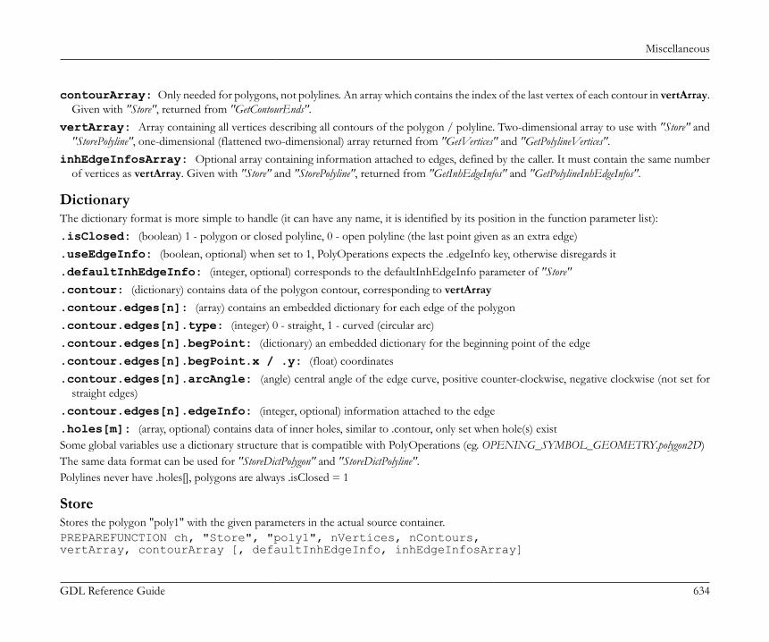
Miscellaneous
GDL Reference Guide 634
contourArray: Only needed for polygons, not polylines. An array which contains the index of the last vertex of each contour in vertArray.Given with "Store", returned from "GetContourEnds".
vertArray: Array containing all vertices describing all contours of the polygon / polyline. Two-dimensional array to use with "Store" and"StorePolyline", one-dimensional (flattened two-dimensional) array returned from "GetVertices" and "GetPolylineVertices".
inhEdgeInfosArray: Optional array containing information attached to edges, defined by the caller. It must contain the same numberof vertices as vertArray. Given with "Store" and "StorePolyline", returned from "GetInhEdgeInfos" and "GetPolylineInhEdgeInfos".
DictionaryThe dictionary format is more simple to handle (it can have any name, it is identified by its position in the function parameter list):.isClosed: (boolean) 1 - polygon or closed polyline, 0 - open polyline (the last point given as an extra edge).useEdgeInfo: (boolean, optional) when set to 1, PolyOperations expects the .edgeInfo key, otherwise disregards it.defaultInhEdgeInfo: (integer, optional) corresponds to the defaultInhEdgeInfo parameter of "Store".contour: (dictionary) contains data of the polygon contour, corresponding to vertArray.contour.edges[n]: (array) contains an embedded dictionary for each edge of the polygon.contour.edges[n].type: (integer) 0 - straight, 1 - curved (circular arc).contour.edges[n].begPoint: (dictionary) an embedded dictionary for the beginning point of the edge.contour.edges[n].begPoint.x / .y: (float) coordinates.contour.edges[n].arcAngle: (angle) central angle of the edge curve, positive counter-clockwise, negative clockwise (not set for
straight edges).contour.edges[n].edgeInfo: (integer, optional) information attached to the edge.holes[m]: (array, optional) contains data of inner holes, similar to .contour, only set when hole(s) existSome global variables use a dictionary structure that is compatible with PolyOperations (eg. OPENING_SYMBOL_GEOMETRY.polygon2D)The same data format can be used for "StoreDictPolygon" and "StoreDictPolyline".Polylines never have .holes[], polygons are always .isClosed = 1
StoreStores the polygon "poly1" with the given parameters in the actual source container.PREPAREFUNCTION ch, "Store", "poly1", nVertices, nContours,vertArray, contourArray [, defaultInhEdgeInfo, inhEdgeInfosArray]
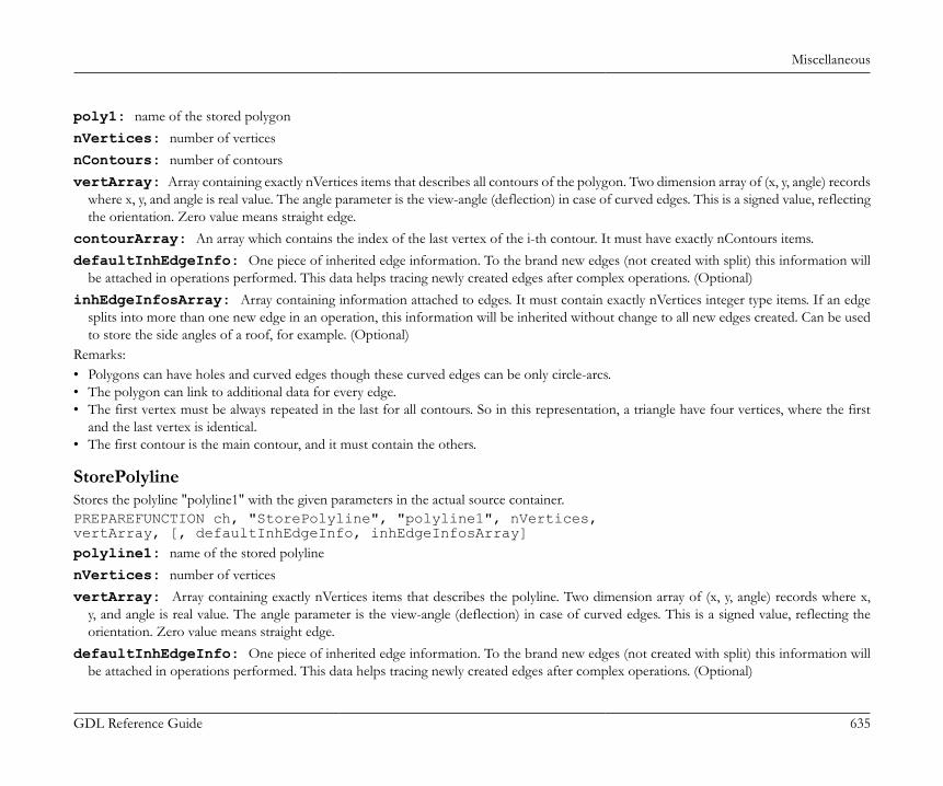
Miscellaneous
GDL Reference Guide 635
poly1: name of the stored polygonnVertices: number of verticesnContours: number of contoursvertArray: Array containing exactly nVertices items that describes all contours of the polygon. Two dimension array of (x, y, angle) records
where x, y, and angle is real value. The angle parameter is the view-angle (deflection) in case of curved edges. This is a signed value, reflectingthe orientation. Zero value means straight edge.
contourArray: An array which contains the index of the last vertex of the i-th contour. It must have exactly nContours items.defaultInhEdgeInfo: One piece of inherited edge information. To the brand new edges (not created with split) this information will
be attached in operations performed. This data helps tracing newly created edges after complex operations. (Optional)inhEdgeInfosArray: Array containing information attached to edges. It must contain exactly nVertices integer type items. If an edge
splits into more than one new edge in an operation, this information will be inherited without change to all new edges created. Can be usedto store the side angles of a roof, for example. (Optional)
Remarks:• Polygons can have holes and curved edges though these curved edges can be only circle-arcs.• The polygon can link to additional data for every edge.• The first vertex must be always repeated in the last for all contours. So in this representation, a triangle have four vertices, where the first
and the last vertex is identical.• The first contour is the main contour, and it must contain the others.
StorePolylineStores the polyline "polyline1" with the given parameters in the actual source container.PREPAREFUNCTION ch, "StorePolyline", "polyline1", nVertices,vertArray, [, defaultInhEdgeInfo, inhEdgeInfosArray]polyline1: name of the stored polylinenVertices: number of verticesvertArray: Array containing exactly nVertices items that describes the polyline. Two dimension array of (x, y, angle) records where x,
y, and angle is real value. The angle parameter is the view-angle (deflection) in case of curved edges. This is a signed value, reflecting theorientation. Zero value means straight edge.
defaultInhEdgeInfo: One piece of inherited edge information. To the brand new edges (not created with split) this information willbe attached in operations performed. This data helps tracing newly created edges after complex operations. (Optional)
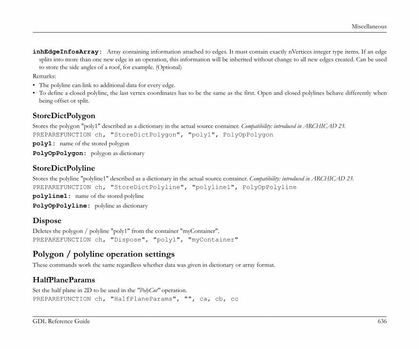
Miscellaneous
GDL Reference Guide 636
inhEdgeInfosArray: Array containing information attached to edges. It must contain exactly nVertices integer type items. If an edgesplits into more than one new edge in an operation, this information will be inherited without change to all new edges created. Can be usedto store the side angles of a roof, for example. (Optional)
Remarks:• The polyline can link to additional data for every edge.• To define a closed polyline, the last vertex coordinates has to be the same as the first. Open and closed polylines behave differently when
being offset or split.
StoreDictPolygonStores the polygon "poly1" described as a dictionary in the actual source container. Compatibility: introduced in ARCHICAD 23.PREPAREFUNCTION ch, "StoreDictPolygon", "poly1", PolyOpPolygonpoly1: name of the stored polygonPolyOpPolygon: polygon as dictionary
StoreDictPolylineStores the polyline "polyline1" described as a dictionary in the actual source container. Compatibility: introduced in ARCHICAD 23.PREPAREFUNCTION ch, "StoreDictPolyline", "polyline1", PolyOpPolylinepolyline1: name of the stored polylinePolyOpPolyline: polyline as dictionary
DisposeDeletes the polygon / polyline "poly1" from the container "myContainer".PREPAREFUNCTION ch, "Dispose", "poly1", "myContainer"
Polygon / polyline operation settingsThese commands work the same regardless whether data was given in dictionary or array format.
HalfPlaneParamsSet the half plane in 2D to be used in the "PolyCut" operation.PREPAREFUNCTION ch, "HalfPlaneParams", "", ca, cb, cc
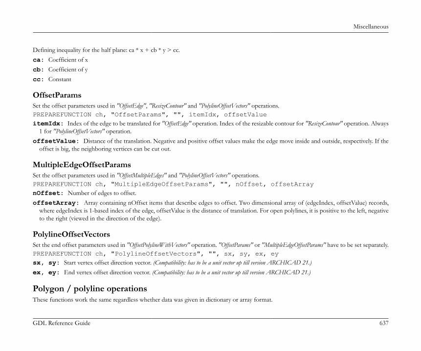
Miscellaneous
GDL Reference Guide 637
Defining inequality for the half plane: ca * x + cb * y > cc.ca: Coefficient of xcb: Coefficient of ycc: Constant
OffsetParamsSet the offset parameters used in "OffsetEdge", "ResizeContour" and "PolylineOffsetVectors" operations.PREPAREFUNCTION ch, "OffsetParams", "", itemIdx, offsetValueitemIdx: Index of the edge to be translated for "OffsetEdge" operation. Index of the resizable contour for "ResizeContour" operation. Always
1 for "PolylineOffsetVectors" operation.offsetValue: Distance of the translation. Negative and positive offset values make the edge move inside and outside, respectively. If the
offset is big, the neighboring vertices can be cut out.
MultipleEdgeOffsetParamsSet the offset parameters used in "OffsetMultipleEdges" and "PolylineOffsetVectors" operations.PREPAREFUNCTION ch, "MultipleEdgeOffsetParams", "", nOffset, offsetArraynOffset: Number of edges to offset.offsetArray: Array containing nOffset items that describe edges to offset. Two dimensional array of (edgeIndex, offsetValue) records,
where edgeIndex is 1-based index of the edge, offsetValue is the distance of translation. For open polylines, it is positive to the left, negativeto the right (viewed in the direction of the edge).
PolylineOffsetVectorsSet the end offset parameters used in "OffsetPolylineWithVectors" operation. "OffsetParams" or "MultipleEdgeOffsetParams" have to be set separately.PREPAREFUNCTION ch, "PolylineOffsetVectors", "", sx, sy, ex, eysx, sy: Start vertex offset direction vector. (Compatibility: has to be a unit vector up till version ARCHICAD 21.)ex, ey: End vertex offset direction vector. (Compatibility: has to be a unit vector up till version ARCHICAD 21.)
Polygon / polyline operationsThese functions work the same regardless whether data was given in dictionary or array format.
Miscellaneous
GDL Reference Guide 638
In the following polygon operations the "poly1", "poly2" source polygons and "polyline1" source polyline are located in the source container.The resulting polygons / polylines are stored in the destination container with a unique name started with "resPolygonID" or "resPolylineID",where "ID" is a number. These names are generally returned in an array.
+ - /Executes the "OP" operation with "poly1" and "poly2" polygons and puts the new values into the given parameters. The return value is thenumber of the generated polygonsdim resPolyIDArray[]nPgon = CALLFUNCTION (ch, "poly1 OP poly2", "", resPolyIDArray)OP: can be:+: Polygon addition-: Polygon subtraction/: Polygon intersection
resPolyIDArray: Array of resulting polygon identifiers.
ClipPolylineClip a polyline with a polygondim resPolyIDArray[]nPline = CALLFUNCTION (ch, "ClipPolyline", "polyline1 poly1", resPolyIDArray)polyline1: Name of the polyline in the source container.poly1: Name of the clip polygon in the source container.resPolyIDArray: Array of resulting polyline identifiers.
CopyPolygonCopying a polygon / polyline from the source container to the destination containerdim resPolyIDArray[]nPgon = CALLFUNCTION (ch, "CopyPolygon", "poly1", resPolyIDArray)
RegularizeRegularizing a polygon - Making it geometrically valid.dim resPolyIDArray[]nPgon = CALLFUNCTION (ch, "Regularize", "poly1", resPolyIDArray)
Miscellaneous
GDL Reference Guide 639
A polygon is valid if• Its first boundary contains all the others• Is oriented correctly (the main contour is a positively oriented curve, the rest is oriented negatively)• Has no self-intersections• Its area is not zero• Has no zero length edges
PolyCutIntersecting the polygon with a halfplane.The halfplane must be set with a "HalfPlaneParams" command. The result will be regularized.dim resPolyIDArray[]nPgon = CALLFUNCTION (ch, "PolyCut", "poly1", resPolyIDArray)
OffsetEdgeTranslating an edge of a polygon perpendicularly to its direction.The edge index and translation offset must be set with an "OffsetParams" command. The result will be regularized.dim resPolyIDArray[]nPgon = CALLFUNCTION (ch, "OffsetEdge", "poly1", resPolyIDArray)
OffsetMultipleEdgesTranslating multiple edges of a polygon perpendicularly to its direction.The edge indices and translation offsets must be set with an "MultipleEdgeOffsetParams" command. The result will be regularized.dim resPolyIDArray[]nPgon = CALLFUNCTION (ch, "OffsetMultipleEdges", "poly1", resPolyIDArray)
OffsetPolylineTranslating all edges of a polyline perpendicularlyThe translation offset must be set with an "OffsetParams" command.dim resPolyIDArray[]nPline = CALLFUNCTION (ch, "OffsetPolyline", "polyline1", resPolyIDArray)

Miscellaneous
GDL Reference Guide 640
OffsetPolylineWithVectorsTranslating all edges of an open polyline perpendicularly, and moving the endpoints along a vectorThe translation vectors and offset must be set with "PolylineOffsetVectors" and "OffsetParams" commands.dim resPolyIDArray[]nPline = CALLFUNCTION (ch, "OffsetPolylineWithVectors", "polyline1", resPolyIDArray)Gives Input argument error for closed polylines
ResizeContourEnlarges or shrinks a contour of a polygon.The contour index and translation offset must be set with an "OffsetParams" command. The result will be regularized.dim resPolyIDArray[]nPgon = CALLFUNCTION (ch, "ResizeContour", "poly1", resPolyIDArray)
CentreOfGravityComputes the centre of gravity of a polygon. Compatibility: introduced in ARCHICAD 22.n = CALLFUNCTION (ch, "CentreOfGravity", "poly1", x, y)Returned values:n: 1 on success, 0 if the centre of gravity is not well-defined, eg. the polygon was self-intersecting.x, y: The coordinates of the centre of gravity.
Get resulting polygons / polylines
Array
GetSourcePolygons, GetSourcePolylinesGetting all polygon / polyline names from the actual source container.dim resPolyIDArray[], resPolylineIDArray[]nPgon = CALLFUNCTION (ch, "GetSourcePolygons", "", resPolyIDArraynPline = CALLFUNCTION (ch, "GetSourcePolylines", "", resPolylineIDArray
GetDestinationPolygons, GetDestinationPolylinesGetting all polygon / polyline names from the actual destination container.
Miscellaneous
GDL Reference Guide 641
dim resPolyIDArray[], resPolylineIDArray[]nPgon = CALLFUNCTION (ch, "GetDestinationPolygons", "", resPolyIDArray)nPline = CALLFUNCTION (ch, "GetDestinationPolylines", "", resPolylineIDArray
GetVertices, GetPolylineVerticesGetting the resulting polygon / polyline vertices after any polygon / polyline operation call.The polygon / polyline with name "polygonID" or "polylineID" is located in the destination container.dim resVertices[], resPolylineVertices[]nVertices = CALLFUNCTION (ch, "GetVertices", polygonID, resVertices)nVertices = CALLFUNCTION (ch, "GetPolylineVertices", polylineID, resPolylineVertices)
GetContourEndsGetting the resulting polygon contour end indices after any polygon operation call.The polygon with name "polygonID" is located in the destination container.dim contArr[]nContours = CALLFUNCTION (ch, "GetContourEnds", polygonID, contArr)
GetInhEdgeInfos, GetPolylineInhEdgeInfosGetting the resulting polygon contour / polyline information after any polygon / polyline operation call.dim inhEdgeInfosArr[], polylineInhEdgeInfosArr[]nEdgeInfos = CALLFUNCTION (ch, "GetInhEdgeInfos", polygonID, inhEdgeInfosArr)nEdgeInfos = CALLFUNCTION (ch, "GetPolylineInhEdgeInfos", polylineID, polylineInhEdgeInfosArr)The polygon / polyline with name "polygonID" or "polylineID" is located in the destination container.
Dictionary
GetSourceDictPolygon, GetSourceDictPolylineGetting the source polygon / polyline as a dictionary. Compatibility: introduced in ARCHICAD 23.The polygon / polyline with name "polygonID" or "polylineID" is located in the source container.dict PolyOperationsPolygon, PolyOperationsPolylineCALLFUNCTION (ch, "GetSourceDictPolygon", polygonID, PolyOperationsPolygonCALLFUNCTION (ch, "GetSourceDictPolyline", polylineID, PolyOperationsPolyline
Miscellaneous
GDL Reference Guide 642
GetDestinationDictPolygon, GetDestinationDictPolylineGetting the resulting polygon / polyline as a dictionary after any polygon / polyline operation call. Compatibility: introduced in ARCHICAD 23.The polygon / polyline with name "polygonID" or "polylineID" is located in the destination container.dict PolyOperationsPolygon, PolyOperationsPolylineCALLFUNCTION (ch, "GetDestinationDictPolygon", polygonID, PolyOperationsPolygon)CALLFUNCTION (ch, "GetDestinationDictPolyline", polylineID, PolyOperationsPolyline
Closing channelCloses channel "ch". Deletes all of the stored polygons / polylines.CLOSEADDONSCOPE (ch)
AUTOTEXT GUIDEIt’s not part of GDL itself. ARCHICAD will substitute all references to autotext fields in whatever GDL output it finds them. For example, ifyou write <PROJECTSTATUS> in the parameter string of a text2 command, ARCHICAD will nicely replace it with the actual value. All thisis invisible to GDL – consequently the size and other attributes of the text are not measurable.
Project info keywords
PROJECTNAMEPROJECTNUMBERPROJECTSTATUSDATEOFISSUESITEFULLADDRESS
SITEADDRESS1SITEADDRESS2SITEADDRESS3SITECITYSITESTATE
SITEPOSTCODESITECOUNTRYKEYWORDSNOTESARCHITECTNAME

Miscellaneous
GDL Reference Guide 643
ARCHITECTPOSITIONCADTECHNICIANARCHITECTCOMPANYARCHITECTFULLADDRESSARCHITECTADDRESS1
ARCHITECTADDRESS2ARCHITECTADDRESS3ARCHITECTCITYARCHITECTSTATEARCHITECTPOSTCODE
ARCHITECTCOUNTRYARCHITECTEMAILARCHITECTPHONEARCHITECTFAXARCHITECTWEB
CLIENTNAMECLIENTCOMPANYCLIENTFULLADDRESSCLIENTADDRESS1CLIENTADDRESS2
CLIENTADDRESS3CLIENTCITYCLIENTSTATECLIENTPOSTCODECLIENTCOUNTRY
CLIENTEMAILCLIENTPHONECLIENTFAX
General
SHORTDATE
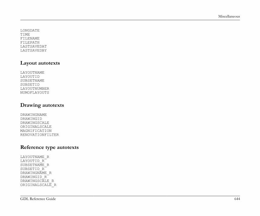
Miscellaneous
GDL Reference Guide 644
LONGDATETIMEFILENAMEFILEPATHLASTSAVEDATLASTSAVEDBY
Layout autotexts
LAYOUTNAMELAYOUTIDSUBSETNAMESUBSETIDLAYOUTNUMBERNUMOFLAYOUTS
Drawing autotexts
DRAWINGNAMEDRAWINGIDDRAWINGSCALEORIGINALSCALEMAGNIFICATIONRENOVATIONFILTER
Reference type autotexts
LAYOUTNAME_RLAYOUTID_RSUBSETNAME_RSUBSETID_RDRAWINGNAME_RDRAWINGID_RDRAWINGSCALE_RORIGINALSCALE_R
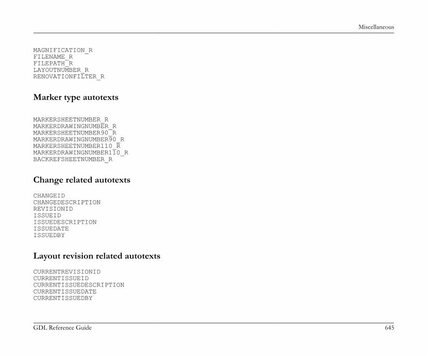
Miscellaneous
GDL Reference Guide 645
MAGNIFICATION_RFILENAME_RFILEPATH_RLAYOUTNUMBER_RRENOVATIONFILTER_R
Marker type autotexts
MARKERSHEETNUMBER_RMARKERDRAWINGNUMBER_RMARKERSHEETNUMBER90_RMARKERDRAWINGNUMBER90_RMARKERSHEETNUMBER110_RMARKERDRAWINGNUMBER110_RBACKREFSHEETNUMBER_R
Change related autotexts
CHANGEIDCHANGEDESCRIPTIONREVISIONIDISSUEIDISSUEDESCRIPTIONISSUEDATEISSUEDBY
Layout revision related autotexts
CURRENTREVISIONIDCURRENTISSUEIDCURRENTISSUEDESCRIPTIONCURRENTISSUEDATECURRENTISSUEDBY
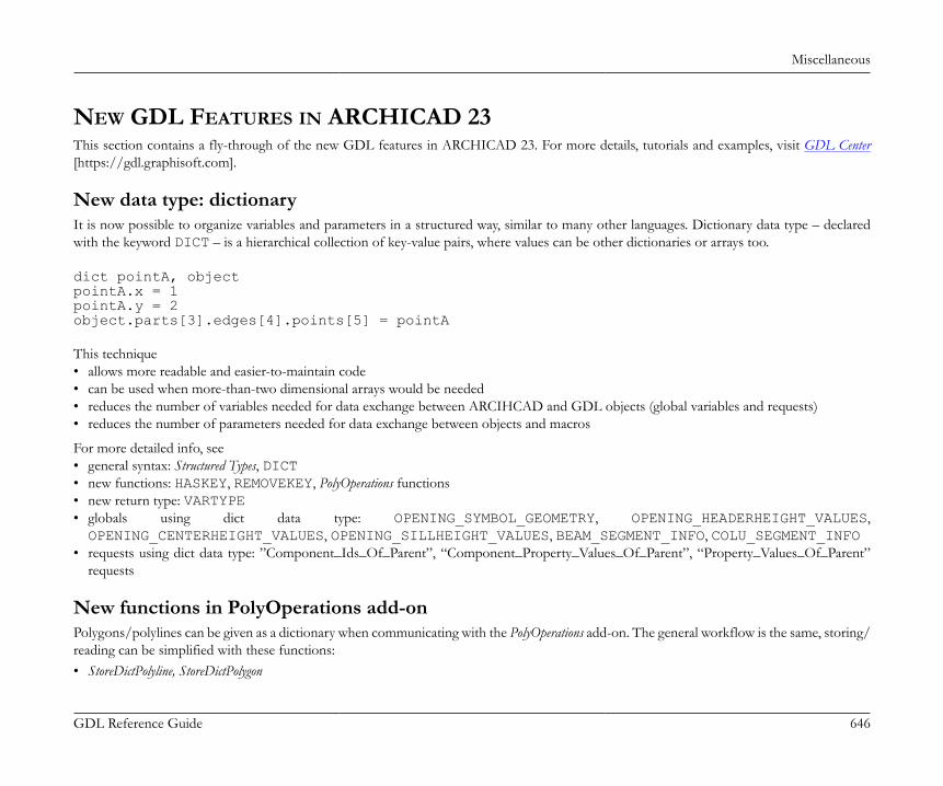
Miscellaneous
GDL Reference Guide 646
NEW GDL FEATURES IN ARCHICAD 23This section contains a fly-through of the new GDL features in ARCHICAD 23. For more details, tutorials and examples, visit GDL Center[https://gdl.graphisoft.com].
New data type: dictionaryIt is now possible to organize variables and parameters in a structured way, similar to many other languages. Dictionary data type – declaredwith the keyword DICT – is a hierarchical collection of key-value pairs, where values can be other dictionaries or arrays too.
dict pointA, objectpointA.x = 1pointA.y = 2object.parts[3].edges[4].points[5] = pointA This technique• allows more readable and easier-to-maintain code• can be used when more-than-two dimensional arrays would be needed• reduces the number of variables needed for data exchange between ARCIHCAD and GDL objects (global variables and requests)• reduces the number of parameters needed for data exchange between objects and macros
For more detailed info, see• general syntax: Structured Types, DICT• new functions: HASKEY, REMOVEKEY, PolyOperations functions• new return type: VARTYPE• globals using dict data type: OPENING_SYMBOL_GEOMETRY, OPENING_HEADERHEIGHT_VALUES,OPENING_CENTERHEIGHT_VALUES, OPENING_SILLHEIGHT_VALUES, BEAM_SEGMENT_INFO, COLU_SEGMENT_INFO
• requests using dict data type: ”Component_Ids_Of_Parent”, “Component_Property_Values_Of_Parent”, “Property_Values_Of_Parent”requests
New functions in PolyOperations add-onPolygons/polylines can be given as a dictionary when communicating with the PolyOperations add-on. The general workflow is the same, storing/reading can be simplified with these functions:• StoreDictPolyline, StoreDictPolygon
Miscellaneous
GDL Reference Guide 647
• GetSourceDictPolyline, GetSourceDictPolygon• GetDestinationDictPolyline, GetDestinationDictPolygonThe dictionary structure is the same as OPENING_SYMBOL_GEOMETRY.polygon2D. For more detailed info, see the Polygon OperationsExtension – Polygon / polyline management – the section called “Dictionary”.
New tool: OpeningThe new opening tool’s 2D symbol is a GDL object. New symbols can be created using the subtype General GDL Object /Documentation Element / Opening Symbol. An opening has two independent symbols, one shown when the opening is cut(in a wall), the other when the opening is viewed (in a slab).For more detailed info, see• OPENING_SYMBOL_DISPLAY• OPENING_SYMBOL_GEOMETRY• OPENING_HEIGHT• OPENING_WIDTH• OPENING_HEADERHEIGHT_VALUES• OPENING_CENTERHEIGHT_VALUES• OPENING_SILLHEIGHT_VALUES• GLOB_ELEM_TYPE
Updated tools: Beam and ColumnWith the updated Beam and Column tools it is possible to model multi-segmented elements. New labels can be chosen to be placed on theelements or on segments, labels placed on segments receive a new GLOB_ELEM_TYPE. Most of the Beam and Column global variables areavaliable for them, for availability details see Beam and Column global variables sections.For more detailed info, see• GLOB_ELEM_TYPE• BEAM_SEGMENT_INDEX• COLU_SEGMENT_INDEX• BEAM_SEGMENT_INFO• COLU_SEGMENT_INFO• deprecated BEAM_CROSSSECTION_TYPE• deprecated COLU_CROSSSECTION_TYPE

Miscellaneous
GDL Reference Guide 648
• deprecated ac_beam_crosssection_type• deprecated ac_colu_crosssection_type
New Property requestsFrom ARCHICAD 23 Building Materials can have Properties and Classifications. The properties of the building materials are referred to ascomponent properties, as these properties belong to a component of the parent element. To display these properties new REQUESTs havebeen introduced, which are available in Labels.The input and output values of “Component_Ids_Of_Parent” and “Component_Property_Values_Of_Parent” requests are in the newdictionary format, “Component_Properties_Of_Parent” has the same input and output data structure as the existing “Properties_Of_Parent”request.• “Component_Ids_Of_Parent”:
The available Building Material components in the parent element are identified by ARCHICAD, these IDs are available through the“Component_Ids_Of_Parent” request.
• “Component_Property_Values_Of_Parent”:To get the component property values of a parent element, the new "Component_Property_Values_Of_Parent” request can be used. Itreturns the property values for a given component with any number of given property IDs.
• “Component_Properties_Of_Parent”:For the Property selection on the User Interface the “Component_Properties_Of_Parent” has been introduced. This request is similar to“Properties_Of_Parent”, except that it returns the available component properties of the parent element.
• “Property_Values_Of_Parent”:A new request version of the “Property_Value_Of_Parent” request is available: “Property_Values_Of_Parent”. This request’s input andoutput values are defined in the new dictionary format. Unlike “Property_Value_Of_Parent”, multiple property IDs can be defined asdictionary keys, and multiple property values are returned.
Diagnostics modeThere is a new menu command that allows easier debugging where the GDL Debugger doesn’t work (complex tools like Curtain Wall, Stair,Railing, Opening or debugging the contents of dictionaries). In the Library Developer Menu (it can be added via Work Environment / Menus)the Library Part Diagnostics Mode menu item toggles the GLOB_DIAGNOSTICS_MODE global. It can be used to write conditional PRINTcommands and/or show hidden parameters on the UI that control the debugging process. The model is not automatically rebuilt after togglingthe menu, use Rebuild & Regenerate (Ctrl-Alt-Shift-R) to re-run the scripts.Some ARCHICAD library parts use this feature, make sure to publish plans with the menu item turned off.
Miscellaneous
GDL Reference Guide 649
Command updates and extended versions• TUBE and TUBE{2}:
Edge elimination (automatically hidden lines where two faces meet in the same plane with the same surface) is possible with these commandstoo. Similarly to CPRISM_{3}, masks can be given for the whole body to control base, end, longitudinal and sectional edges.
• new COONS{2}:It is possible to hide the boundaries of a COONS with a smooth surface.
• new RULEDSEGMENTED{2}:It is possible to assign different materials to each segment and control the texture projection.
• “ASSOCLP_PARVALUE” request:“ASSOCLP_PARVALUE” and “ASSOCLP_PARVALUE_WITH_DESCRIPTION” requests can handle parameters of profile type.
• Documentation:We made some clarifications in the Reference Guide, it is recommendeed to look them up in case of using these:• AC_LabelPointerLineType - type• AC_LabelPointerPen - type• AC_bLabelFrame - type• ac_holeSideMaterial – previously existing, but undocumented• ac_holeMaterialCurved – previously existing, but undocumented• ac_beam_cut_linetype – previously existing, but undocumented• ac_beam_overhead_linetype – previously documented, but non-existing• VARTYPE – undocumented return value 3 for groups, new value 4 for dictionaries• "CentreOfGravity" – previously existing, but undocumented PolyOperations function
IFC4The IFC Add-on uses IFC4 standard instead of IFC 2×3. There are some minor changes in these these fix-named parameters:• ifc_optype - new opening type for Doors• ifc_optype, ifc_CapacityByWeight and ifc_CapacityByNumber - deprecated for Transport Elements• ifc_subtype - new types for MEP elementsDetails are listed in the the section called “Parameters of IFC add-on”.
Miscellaneous
GDL Reference Guide 650
New source format with LP_XMLConverterThe LP_XMLConverter tool can convert to and from a new type of source format called HSF. Library parts are stored in the same folder asimages, the xml source is split into smaller xml files and separate .gdl scripts.LCF and GSM made from XML is fully compatible in ARCHICAD with one made from HSF, conversion between HSF and XML can bedone using LP_XMLConverter via the GSM format.For more information about the LP_XMLConverter tool, check out the GDL Center Tips and Tricks [https://gdl.graphisoft.com/tips-and-tricks/how-to-use-the-lp_xmlconverter-tool]
Index
GDL Reference Guide 651
INDEX
SYNTAX LISTING OF GDL COMMANDS
AABS (x)
ACS (x)
ADD dx, dy, dz
ADD2 x, y
ADDGROUP (g_expr1, g_expr2)
ADDGROUP{2} (g_expr1, g_expr2, edgeColor, materialId, materialColor [, operationStatus])
ADDGROUP{3} (g_expr1, g_expr2, edgeColor, materialId, materialColor [, operationStatus])
LIGHT red, green, blue, shadow, radius, alpha, beta, angle_falloff, distance1, distance2, distance_falloff [[,] ADDITIONAL_DATA name1 = value1, name2 = value2, ...]
DEFINE MATERIAL name [,] BASED_ON orig_name [,] PARAMETERS name1 = expr1 [, ...] [[,] ADDITIONAL_DATA name1 = expr1 [, ...]]
ADDX dx
ADDY dy
ADDZ dz
LOCK ALL ["name1" [, "name2", ..., "namen"]]
HIDEPARAMETER ALL ["name1" [, "name2", ..., "namen"]]
Index
GDL Reference Guide 652
CALL macro_name_string [,] PARAMETERS [ALL][name1=value1, ..., namen=valuen][[,] RETURNED_PARAMETERS r1, r2, ...]
APPLICATION_QUERY (extension_name, parameter_string, variable1, variable2, ...)
ARC r, alpha, beta
ARC2 x, y, r, alpha, beta
ARMC r1, r2, l, h, d, alpha
ARME l, r1, r2, h, d
ASN (x)
ATN (x)
BBASE
DEFINE MATERIAL name [,] BASED_ON orig_name [,] PARAMETERS name1 = expr1 [, ...] [[,] ADDITIONAL_DATA name1 = expr1 [, ...]]
BEAM left_material, right_material, vertical_material, top_material, bottom_material, height, x1, x2, x3, x4, y1, y2, y3, y4, t, mask1, mask2, mask3, mask4
BINARY mode [, section, elementID]
BINARYPROP
BITSET (x, b [, expr])
BITTEST (x, b)
BLOCK a, b, c
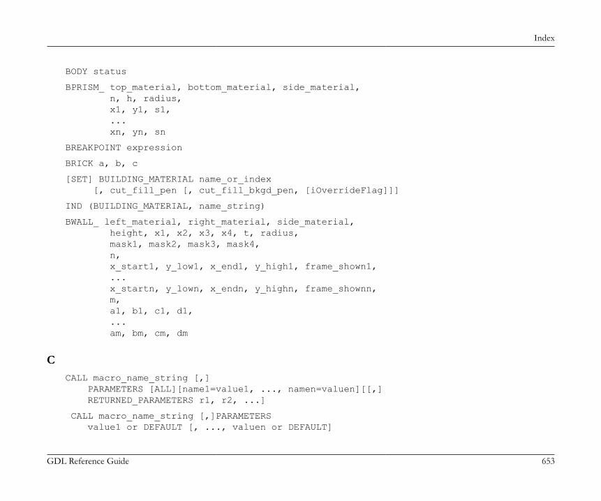
Index
GDL Reference Guide 653
BODY status
BPRISM_ top_material, bottom_material, side_material, n, h, radius, x1, y1, s1, ... xn, yn, sn
BREAKPOINT expression
BRICK a, b, c
[SET] BUILDING_MATERIAL name_or_index [, cut_fill_pen [, cut_fill_bkgd_pen, [iOverrideFlag]]]
IND (BUILDING_MATERIAL, name_string)
BWALL_ left_material, right_material, side_material, height, x1, x2, x3, x4, t, radius, mask1, mask2, mask3, mask4, n, x_start1, y_low1, x_end1, y_high1, frame_shown1, ... x_startn, y_lown, x_endn, y_highn, frame_shownn, m, a1, b1, c1, d1, ... am, bm, cm, dm
CCALL macro_name_string [,] PARAMETERS [ALL][name1=value1, ..., namen=valuen][[,] RETURNED_PARAMETERS r1, r2, ...]
CALL macro_name_string [,]PARAMETERS value1 or DEFAULT [, ..., valuen or DEFAULT]

Index
GDL Reference Guide 654
CALL macro_name_string [, parameter_list]
CALLFUNCTION (channel, function_name, parameter, variable1 [, variable2, ...])
CEIL (x)
CIRCLE r
CIRCLE2 x, y, r
CLOSE channel
CLOSEADDONSCOPE channel
COMPONENT name, quantity, unit [, proportional_with, code, keycode, unitcode]
CONE h, r1, r2, alpha1, alpha2
COONS n, m, mask, x11, y11, z11, ..., x1n, y1n, z1n, x21, y21, z21, ..., x2n, y2n, z2n, x31, y31, z31, ..., x3m, y3m, z3m, x41, y41, z41, ..., x4m, y4m, z4m
COONS{2} n, m, mask, x11, y11, z11, ..., x1n, y1n, z1n, x21, y21, z21, ..., x2n, y2n, z2n, x31, y31, z31, ..., x3m, y3m, z3m, x41, y41, z41, ..., x4m, y4m, z4m
COOR wrap, vert1, vert2, vert3, vert4
COOR{2} wrap_method, wrap_flags, vert1, vert2, vert3, vert4
COOR{3} wrapping_method, wrap_flags, origin_X, origin_Y, origin_Z, endOfX_X, endOfX_Y, endOfX_Z, endOfY_X, endOfY_Y, endOfY_Z, endOfZ_X, endOfZ_Y, endOfZ_Z

Index
GDL Reference Guide 655
COS (x)
CPRISM_ top_material, bottom_material, side_material, n, h, x1, y1, s1, ..., xn, yn, sn
CPRISM_{2} top_material, bottom_material, side_material, n, h, x1, y1, alpha1, s1, mat1, ... xn, yn, alphan, sn, matn
CPRISM_{3} top_material, bottom_material, side_material, mask, n, h, x1, y1, alpha1, s1, mat1, ... xn, yn, alphan, sn, matn
CPRISM_{4} top_material, bottom_material, side_material, mask, n, h, x1, y1, alpha1, s1, mat1, ... xn, yn, alphan, sn, matn
CREATEGROUPWITHMATERIAL (g_expr, repl_directive, pen, material)
CROOF_ top_material, bottom_material, side_material, n, xb, yb, xe, ye, height, angle, thickness, x1, y1, alpha1, s1, ... xn, yn, alphan, sn
CROOF_{2} top_material, bottom_material, side_material, n, xb, yb, xe, ye, height, angle, thickness, x1, y1, alpha1, s1, mat1, ... xn, yn, alphan, sn, matn
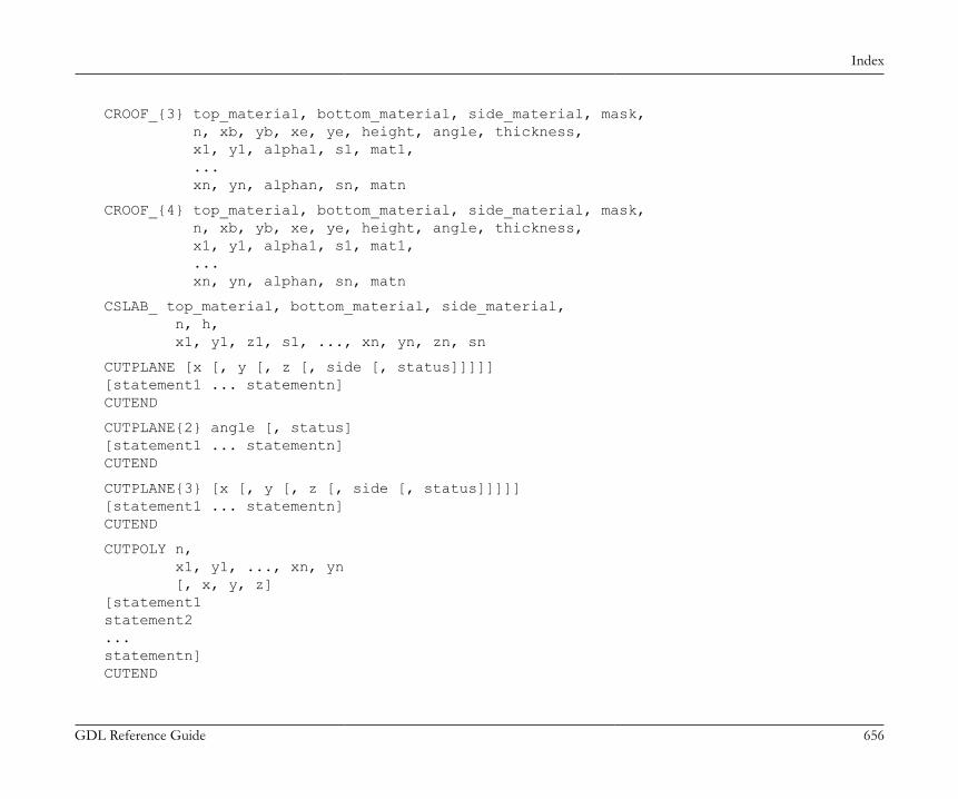
Index
GDL Reference Guide 656
CROOF_{3} top_material, bottom_material, side_material, mask, n, xb, yb, xe, ye, height, angle, thickness, x1, y1, alpha1, s1, mat1, ... xn, yn, alphan, sn, matn
CROOF_{4} top_material, bottom_material, side_material, mask, n, xb, yb, xe, ye, height, angle, thickness, x1, y1, alpha1, s1, mat1, ... xn, yn, alphan, sn, matn
CSLAB_ top_material, bottom_material, side_material, n, h, x1, y1, z1, s1, ..., xn, yn, zn, sn
CUTPLANE [x [, y [, z [, side [, status]]]]][statement1 ... statementn]CUTEND
CUTPLANE{2} angle [, status][statement1 ... statementn]CUTEND
CUTPLANE{3} [x [, y [, z [, side [, status]]]]][statement1 ... statementn]CUTEND
CUTPOLY n, x1, y1, ..., xn, yn [, x, y, z][statement1statement2...statementn]CUTEND
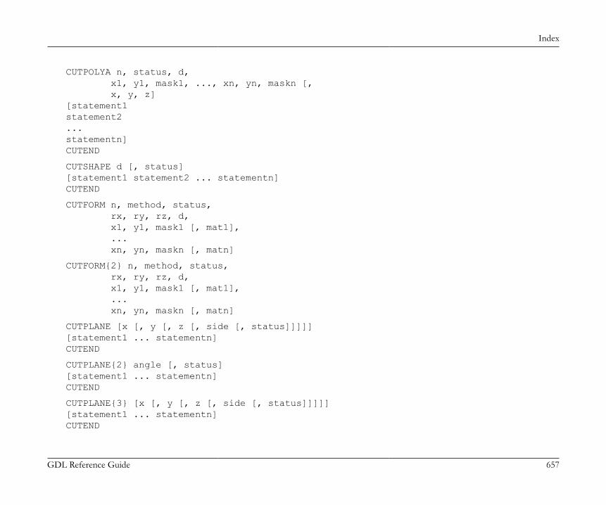
Index
GDL Reference Guide 657
CUTPOLYA n, status, d, x1, y1, mask1, ..., xn, yn, maskn [, x, y, z][statement1statement2...statementn]CUTEND
CUTSHAPE d [, status][statement1 statement2 ... statementn]CUTEND
CUTFORM n, method, status, rx, ry, rz, d, x1, y1, mask1 [, mat1], ... xn, yn, maskn [, matn]
CUTFORM{2} n, method, status, rx, ry, rz, d, x1, y1, mask1 [, mat1], ... xn, yn, maskn [, matn]
CUTPLANE [x [, y [, z [, side [, status]]]]][statement1 ... statementn]CUTEND
CUTPLANE{2} angle [, status][statement1 ... statementn]CUTEND
CUTPLANE{3} [x [, y [, z [, side [, status]]]]][statement1 ... statementn]CUTEND
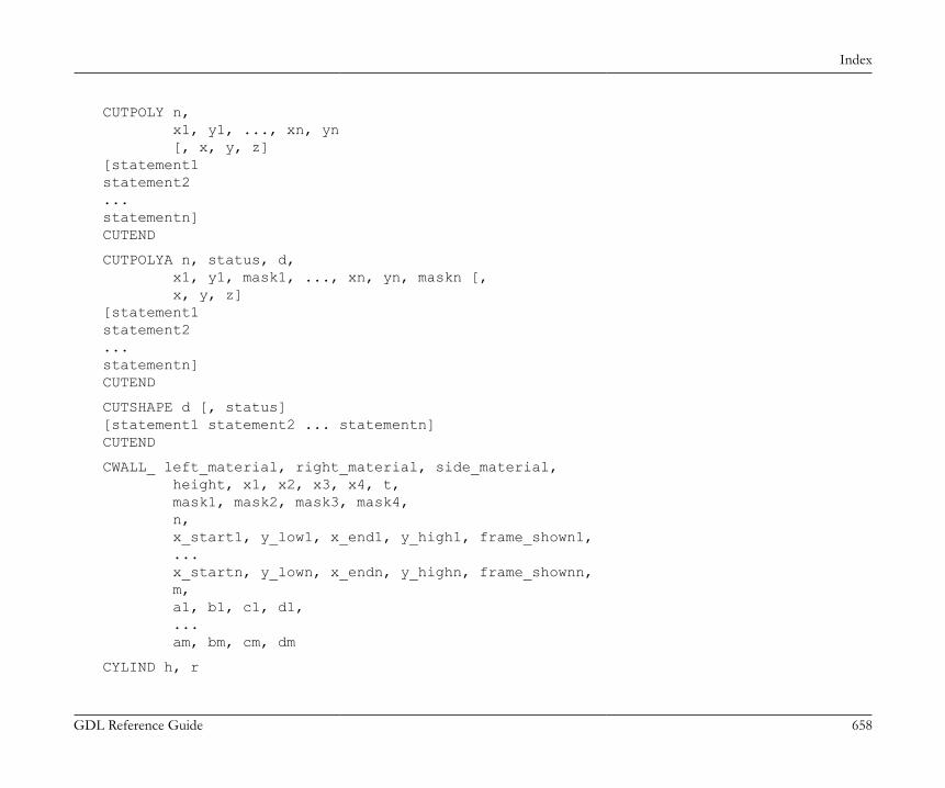
Index
GDL Reference Guide 658
CUTPOLY n, x1, y1, ..., xn, yn [, x, y, z][statement1statement2...statementn]CUTEND
CUTPOLYA n, status, d, x1, y1, mask1, ..., xn, yn, maskn [, x, y, z][statement1statement2...statementn]CUTEND
CUTSHAPE d [, status][statement1 statement2 ... statementn]CUTEND
CWALL_ left_material, right_material, side_material, height, x1, x2, x3, x4, t, mask1, mask2, mask3, mask4, n, x_start1, y_low1, x_end1, y_high1, frame_shown1, ... x_startn, y_lown, x_endn, y_highn, frame_shownn, m, a1, b1, c1, d1, ... am, bm, cm, dm
CYLIND h, r
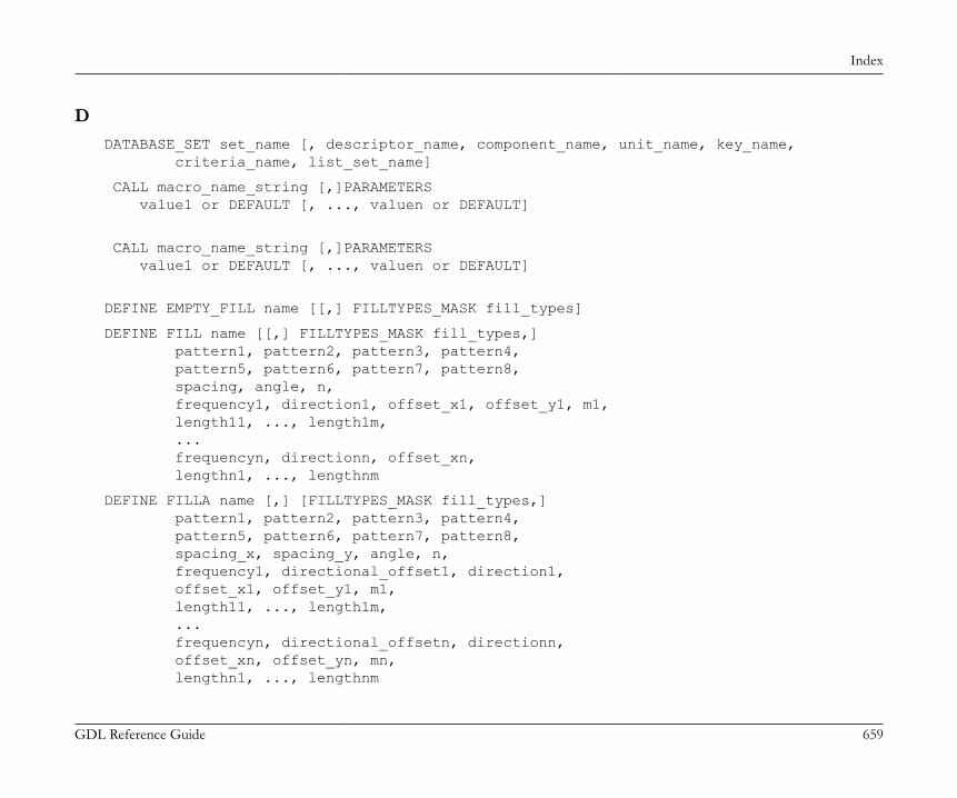
Index
GDL Reference Guide 659
DDATABASE_SET set_name [, descriptor_name, component_name, unit_name, key_name, criteria_name, list_set_name]
CALL macro_name_string [,]PARAMETERS value1 or DEFAULT [, ..., valuen or DEFAULT]
CALL macro_name_string [,]PARAMETERS value1 or DEFAULT [, ..., valuen or DEFAULT]
DEFINE EMPTY_FILL name [[,] FILLTYPES_MASK fill_types]
DEFINE FILL name [[,] FILLTYPES_MASK fill_types,] pattern1, pattern2, pattern3, pattern4, pattern5, pattern6, pattern7, pattern8, spacing, angle, n, frequency1, direction1, offset_x1, offset_y1, m1, length11, ..., length1m, ... frequencyn, directionn, offset_xn, lengthn1, ..., lengthnm
DEFINE FILLA name [,] [FILLTYPES_MASK fill_types,] pattern1, pattern2, pattern3, pattern4, pattern5, pattern6, pattern7, pattern8, spacing_x, spacing_y, angle, n, frequency1, directional_offset1, direction1, offset_x1, offset_y1, m1, length11, ..., length1m, ... frequencyn, directional_offsetn, directionn, offset_xn, offset_yn, mn, lengthn1, ..., lengthnm

Index
GDL Reference Guide 660
DEFINE IMAGE_FILL name image_name [[,] FILLTYPES_MASK fill_types] part1, part2, part3, part4, part5, part6, part7, part8, image_vert_size, image_hor_size, image_mask, image_rotangle
DEFINE LINEAR_GRADIENT_FILL name [[,] FILLTYPES_MASK fill_types]
DEFINE LINE_TYPE name spacing, n, length1, ..., lengthn
DEFINE MATERIAL name type, surface_red, surface_green, surface_blue [, ambient_ce, diffuse_ce, specular_ce, transparent_ce, shining, transparency_attenuation [, specular_red, specular_green, specular_blue, emission_red, emission_green, emission_blue, emission_att]] [, fill_index [, fillcolor_index, texture_index]]
DEFINE MATERIAL name [,] BASED_ON orig_name [,] PARAMETERS name1 = expr1 [, ...] [[,] ADDITIONAL_DATA name1 = expr1 [, ...]]
DEFINE RADIAL_GRADIENT_FILL name [[,] FILLTYPES_MASK fill_types]
DEFINE SOLID_FILL name [[,] FILLTYPES_MASK fill_types]
DEFINE STYLE name font_family, size, anchor, face_code
DEFINE STYLE{2} name font_family, size, face_code
DEFINE SYMBOL_FILL name [,][FILLTYPES_MASK fill_types,] pat1, pat2, pat3, pat4, pat5, pat6, pat7, pat8, spacingx1, spacingy1, spacingx2, spacingy2, angle, scaling1, scaling2, macro_name [,] PARAMETERS [name1 = value1, ..., namen = valuen]
DEFINE SYMBOL_LINE name dash, gap, macro_name PARAMETERS [name1 = value1, ... namen = valuen]
DEFINE TEXTURE name expression, x, y, mask, angle
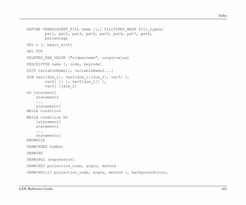
Index
GDL Reference Guide 661
DEFINE TRANSLUCENT_FILL name [[,] FILLTYPES_MASK fill_types] pat1, pat2, pat3, pat4, pat5, pat6, pat7, pat8, percentage
DEL n [, begin_with]
DEL TOP
DELETED_PAR_VALUE ("oldparname", outputvalue)
DESCRIPTOR name [, code, keycode]
DICT variableName1[, variableName2...]
DIM var1[dim_1], var2[dim_1][dim_2], var3[ ], var4[ ][ ], var5[dim_1][ ], var5[ ][dim_2]
DO [statment1 statement2 ... statementn]WHILE condition
WHILE condition DO [statement1 statement2 ... statementn]ENDWHILE
DRAWINDEX number
DRAWING
DRAWING2 [expression]
DRAWING3 projection_code, angle, method
DRAWING3{2} projection_code, angle, method [, backgroundColor,
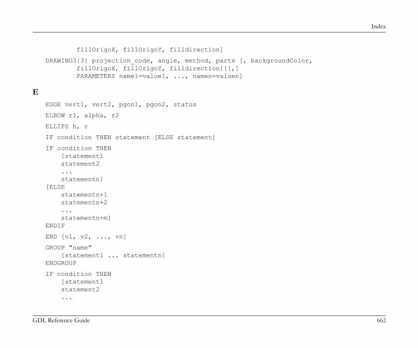
Index
GDL Reference Guide 662
fillOrigoX, fillOrigoY, filldirection]
DRAWING3{3} projection_code, angle, method, parts [, backgroundColor, fillOrigoX, fillOrigoY, filldirection][[,] PARAMETERS name1=value1, ..., namen=valuen]
EEDGE vert1, vert2, pgon1, pgon2, status
ELBOW r1, alpha, r2
ELLIPS h, r
IF condition THEN statement [ELSE statement]
IF condition THEN [statement1 statement2 ... statementn][ELSE statementn+1 statementn+2 ... statementn+m]ENDIF
END [v1, v2, ..., vn]
GROUP "name" [statement1 ... statementn]ENDGROUP
IF condition THEN [statement1 statement2 ...
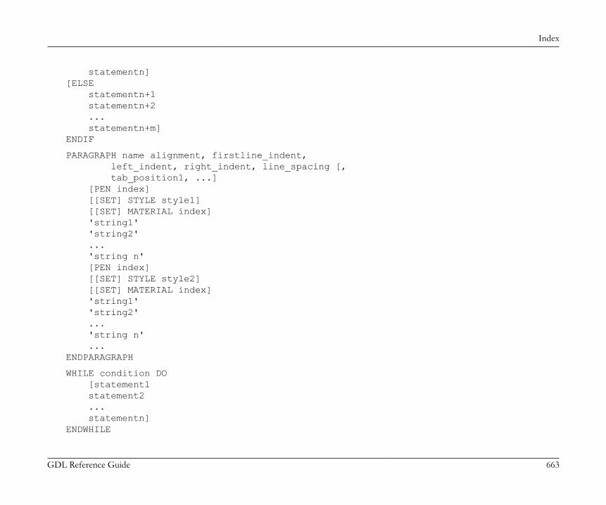
Index
GDL Reference Guide 663
statementn][ELSE statementn+1 statementn+2 ... statementn+m]ENDIF
PARAGRAPH name alignment, firstline_indent, left_indent, right_indent, line_spacing [, tab_position1, ...] [PEN index] [[SET] STYLE style1] [[SET] MATERIAL index] 'string1' 'string2' ... 'string n' [PEN index] [[SET] STYLE style2] [[SET] MATERIAL index] 'string1' 'string2' ... 'string n' ...ENDPARAGRAPH
WHILE condition DO [statement1 statement2 ... statementn]ENDWHILE
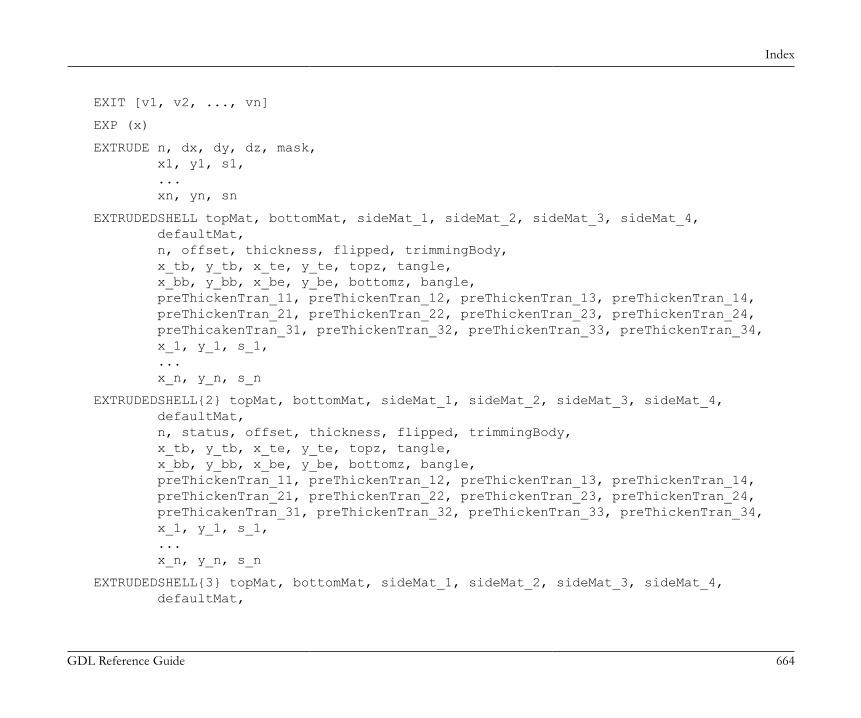
Index
GDL Reference Guide 664
EXIT [v1, v2, ..., vn]
EXP (x)
EXTRUDE n, dx, dy, dz, mask, x1, y1, s1, ... xn, yn, sn
EXTRUDEDSHELL topMat, bottomMat, sideMat_1, sideMat_2, sideMat_3, sideMat_4, defaultMat, n, offset, thickness, flipped, trimmingBody, x_tb, y_tb, x_te, y_te, topz, tangle, x_bb, y_bb, x_be, y_be, bottomz, bangle, preThickenTran_11, preThickenTran_12, preThickenTran_13, preThickenTran_14, preThickenTran_21, preThickenTran_22, preThickenTran_23, preThickenTran_24, preThicakenTran_31, preThickenTran_32, preThickenTran_33, preThickenTran_34, x_1, y_1, s_1, ... x_n, y_n, s_n
EXTRUDEDSHELL{2} topMat, bottomMat, sideMat_1, sideMat_2, sideMat_3, sideMat_4, defaultMat, n, status, offset, thickness, flipped, trimmingBody, x_tb, y_tb, x_te, y_te, topz, tangle, x_bb, y_bb, x_be, y_be, bottomz, bangle, preThickenTran_11, preThickenTran_12, preThickenTran_13, preThickenTran_14, preThickenTran_21, preThickenTran_22, preThickenTran_23, preThickenTran_24, preThicakenTran_31, preThickenTran_32, preThickenTran_33, preThickenTran_34, x_1, y_1, s_1, ... x_n, y_n, s_n
EXTRUDEDSHELL{3} topMat, bottomMat, sideMat_1, sideMat_2, sideMat_3, sideMat_4, defaultMat,
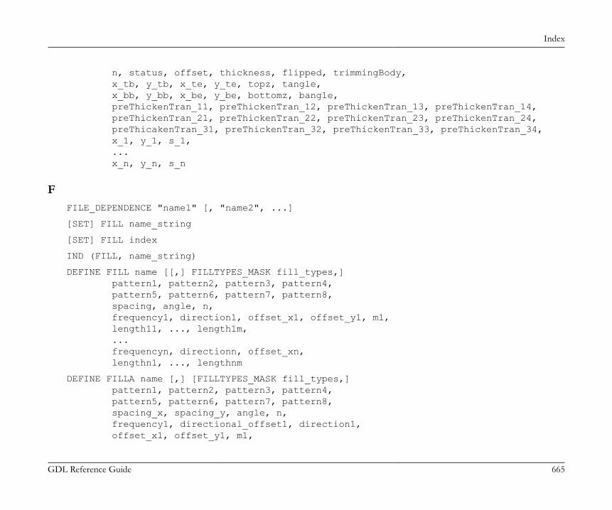
Index
GDL Reference Guide 665
n, status, offset, thickness, flipped, trimmingBody, x_tb, y_tb, x_te, y_te, topz, tangle, x_bb, y_bb, x_be, y_be, bottomz, bangle, preThickenTran_11, preThickenTran_12, preThickenTran_13, preThickenTran_14, preThickenTran_21, preThickenTran_22, preThickenTran_23, preThickenTran_24, preThicakenTran_31, preThickenTran_32, preThickenTran_33, preThickenTran_34, x_1, y_1, s_1, ... x_n, y_n, s_n
FFILE_DEPENDENCE "name1" [, "name2", ...]
[SET] FILL name_string
[SET] FILL index
IND (FILL, name_string)
DEFINE FILL name [[,] FILLTYPES_MASK fill_types,] pattern1, pattern2, pattern3, pattern4, pattern5, pattern6, pattern7, pattern8, spacing, angle, n, frequency1, direction1, offset_x1, offset_y1, m1, length11, ..., length1m, ... frequencyn, directionn, offset_xn, lengthn1, ..., lengthnm
DEFINE FILLA name [,] [FILLTYPES_MASK fill_types,] pattern1, pattern2, pattern3, pattern4, pattern5, pattern6, pattern7, pattern8, spacing_x, spacing_y, angle, n, frequency1, directional_offset1, direction1, offset_x1, offset_y1, m1,

Index
GDL Reference Guide 666
length11, ..., length1m, ... frequencyn, directional_offsetn, directionn, offset_xn, offset_yn, mn, lengthn1, ..., lengthnm
DEFINE SYMBOL_FILL name [,][FILLTYPES_MASK fill_types,] pat1, pat2, pat3, pat4, pat5, pat6, pat7, pat8, spacingx1, spacingy1, spacingx2, spacingy2, angle, scaling1, scaling2, macro_name [,] PARAMETERS [name1 = value1, ..., namen = valuen]
DEFINE SOLID_FILL name [[,] FILLTYPES_MASK fill_types]
DEFINE EMPTY_FILL name [[,] FILLTYPES_MASK fill_types]
DEFINE LINEAR_GRADIENT_FILL name [[,] FILLTYPES_MASK fill_types]
DEFINE RADIAL_GRADIENT_FILL name [[,] FILLTYPES_MASK fill_types]
DEFINE TRANSLUCENT_FILL name [[,] FILLTYPES_MASK fill_types] pat1, pat2, pat3, pat4, pat5, pat6, pat7, pat8, percentage
DEFINE IMAGE_FILL name image_name [[,] FILLTYPES_MASK fill_types] part1, part2, part3, part4, part5, part6, part7, part8, image_vert_size, image_hor_size, image_mask, image_rotangle
VALUES "fill_parameter_name" [[,] FILLTYPES_MASK fill_types], value_definition1 [, value_definition2, ...]
FOR variable_name = initial_value TO end_value [ STEP step_value ] NEXT variable_name
FPRISM_ top_material, bottom_material, side_material, hill_material, n, thickness, angle, hill_height, x1, y1, s1, ... xn, yn, sn
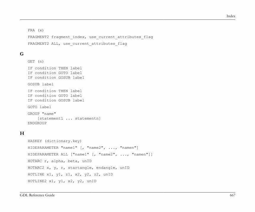
Index
GDL Reference Guide 667
FRA (x)
FRAGMENT2 fragment_index, use_current_attributes_flag
FRAGMENT2 ALL, use_current_attributes_flag
GGET (n)
IF condition THEN labelIF condition GOTO labelIF condition GOSUB label
GOSUB label
IF condition THEN labelIF condition GOTO labelIF condition GOSUB label
GOTO label
GROUP "name" [statement1 ... statementn]ENDGROUP
HHASKEY (dictionary.key)
HIDEPARAMETER "name1" [, "name2", ..., "namen"]
HIDEPARAMETER ALL ["name1" [, "name2", ..., "namen"]]
HOTARC r, alpha, beta, unID
HOTARC2 x, y, r, startangle, endangle, unID
HOTLINE x1, y1, z1, x2, y2, z2, unID
HOTLINE2 x1, y1, x2, y2, unID
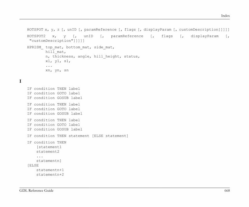
Index
GDL Reference Guide 668
HOTSPOT x, y, z [, unID [, paramReference [, flags [, displayParam [, customDescription]]]]]
HOTSPOT2 x, y [, unID [, paramReference [, flags [, displayParam [, "customDescription"]]]]]
HPRISM_ top_mat, bottom_mat, side_mat, hill_mat, n, thickness, angle, hill_height, status, x1, y1, s1, ... xn, yn, sn
IIF condition THEN labelIF condition GOTO labelIF condition GOSUB label
IF condition THEN labelIF condition GOTO labelIF condition GOSUB label
IF condition THEN labelIF condition GOTO labelIF condition GOSUB label
IF condition THEN statement [ELSE statement]
IF condition THEN [statement1 statement2 ... statementn][ELSE statementn+1 statementn+2

Index
GDL Reference Guide 669
... statementn+m]ENDIF
IND (MATERIAL, name_string)
IND (BUILDING_MATERIAL, name_string)
IND (FILL, name_string)
IND (LINE_TYPE, name_string)
IND (STYLE, name_string)
IND (TEXTURE, name_string)
IND (PROFILE_ATTR, name_string, index)
INITADDONSCOPE (extension, parameter_string1, parameter_string2)
INPUT (channel, recordID, fieldID, variable1 [, variable2, ...])
INT (x)
ISECTGROUP (g_expr1, g_expr2)
ISECTGROUP{2} (g_expr1, g_expr2, edgeColor, materialId, materialColor [, operationStatus])
ISECTGROUP{3} (g_expr1, g_expr2, edgeColor, materialId, materialColor [, operationStatus])
ISECTLINES (g_expr1, g_expr2)
KKILLGROUP g_expr
L[LET] varnam = n
LGT (x)
LIBRARYGLOBAL (object_name, parameter, value)
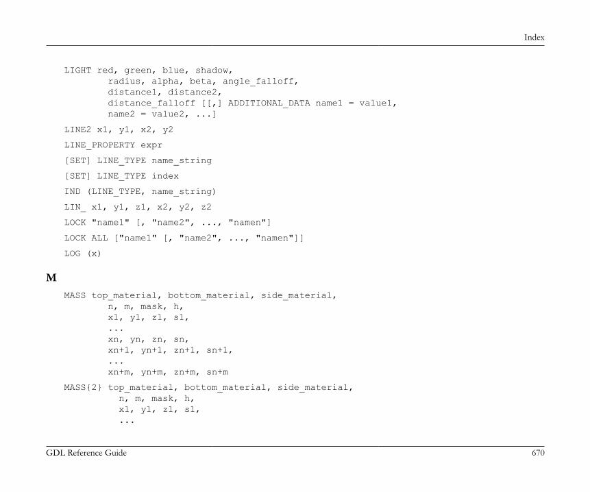
Index
GDL Reference Guide 670
LIGHT red, green, blue, shadow, radius, alpha, beta, angle_falloff, distance1, distance2, distance_falloff [[,] ADDITIONAL_DATA name1 = value1, name2 = value2, ...]
LINE2 x1, y1, x2, y2
LINE_PROPERTY expr
[SET] LINE_TYPE name_string
[SET] LINE_TYPE index
IND (LINE_TYPE, name_string)
LIN_ x1, y1, z1, x2, y2, z2
LOCK "name1" [, "name2", ..., "namen"]
LOCK ALL ["name1" [, "name2", ..., "namen"]]
LOG (x)
MMASS top_material, bottom_material, side_material, n, m, mask, h, x1, y1, z1, s1, ... xn, yn, zn, sn, xn+1, yn+1, zn+1, sn+1, ... xn+m, yn+m, zn+m, sn+m
MASS{2} top_material, bottom_material, side_material, n, m, mask, h, x1, y1, z1, s1, ...
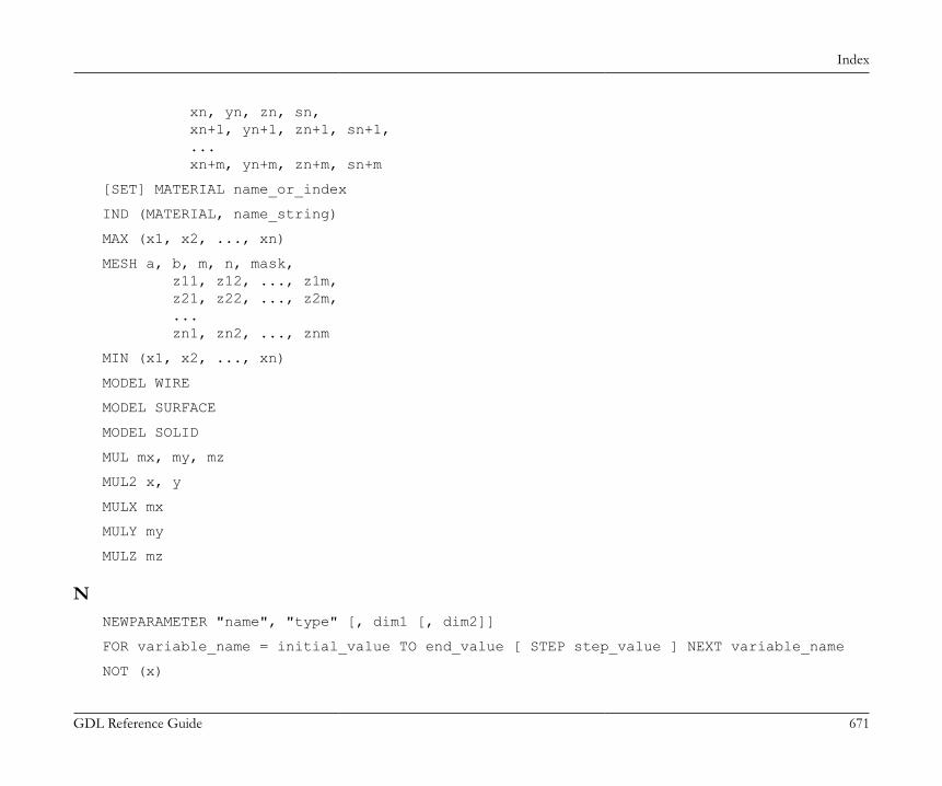
Index
GDL Reference Guide 671
xn, yn, zn, sn, xn+1, yn+1, zn+1, sn+1, ... xn+m, yn+m, zn+m, sn+m
[SET] MATERIAL name_or_index
IND (MATERIAL, name_string)
MAX (x1, x2, ..., xn)
MESH a, b, m, n, mask, z11, z12, ..., z1m, z21, z22, ..., z2m, ... zn1, zn2, ..., znm
MIN (x1, x2, ..., xn)
MODEL WIRE
MODEL SURFACE
MODEL SOLID
MUL mx, my, mz
MUL2 x, y
MULX mx
MULY my
MULZ mz
NNEWPARAMETER "name", "type" [, dim1 [, dim2]]
FOR variable_name = initial_value TO end_value [ STEP step_value ] NEXT variable_name
NOT (x)
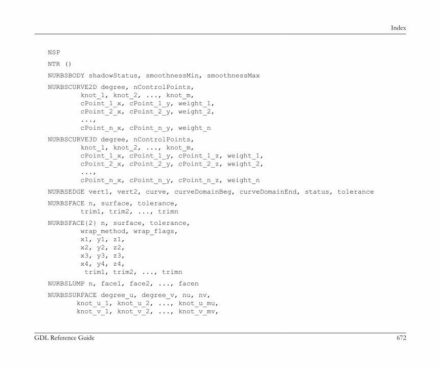
Index
GDL Reference Guide 672
NSP
NTR ()
NURBSBODY shadowStatus, smoothnessMin, smoothnessMax
NURBSCURVE2D degree, nControlPoints, knot_1, knot_2, ..., knot_m, cPoint_1_x, cPoint_1_y, weight_1, cPoint_2_x, cPoint_2_y, weight_2, ..., cPoint_n_x, cPoint_n_y, weight_n
NURBSCURVE3D degree, nControlPoints, knot_1, knot_2, ..., knot_m, cPoint_1_x, cPoint_1_y, cPoint_1_z, weight_1, cPoint_2_x, cPoint_2_y, cPoint_2_z, weight_2, ..., cPoint_n_x, cPoint_n_y, cPoint_n_z, weight_n
NURBSEDGE vert1, vert2, curve, curveDomainBeg, curveDomainEnd, status, tolerance
NURBSFACE n, surface, tolerance, trim1, trim2, ..., trimn
NURBSFACE{2} n, surface, tolerance, wrap_method, wrap_flags, x1, y1, z1, x2, y2, z2, x3, y3, z3, x4, y4, z4, trim1, trim2, ..., trimn
NURBSLUMP n, face1, face2, ..., facen
NURBSSURFACE degree_u, degree_v, nu, nv, knot_u_1, knot_u_2, ..., knot_u_mu, knot_v_1, knot_v_2, ..., knot_v_mv,

Index
GDL Reference Guide 673
cPoint_1_1_x, cPoint_1_1_y, cPoint_1_1_z, weight_1_1, cPoint_1_2_x, cPoint_1_2_y, cPoint_1_2_z, weight_1_2, ..., cPoint_1_nv_x, cPoint_1_nv_y, cPoint_1_nv_z, weight_1_nv, cPoint_2_1_x, cPoint_2_1_y, cPoint_2_1_z, weight_2_1, ..., cPoint_nu_nv_x, cPoint_nu_nv_y, cPoint_nu_nv_z, weight_nu_nv
NURBSTRIM edge, curve, curveDomainBeg, curveDomainEnd, tolerance
NURBSTRIMSINGULAR vertex, curve, curveDomainBeg, curveDomainEnd, tolerance
NURBSVERT x, y, z, hard, tolerance
OOPEN (filter, filename, parameter_string)
OUTPUT channel, recordID, fieldID, expression1 [, expression2, ...]
PPARAGRAPH name alignment, firstline_indent, left_indent, right_indent, line_spacing [, tab_position1, ...] [PEN index] [[SET] STYLE style1] [[SET] MATERIAL index] 'string1' 'string2' ... 'string n' [PEN index] [[SET] STYLE style2] [[SET] MATERIAL index] 'string1'

Index
GDL Reference Guide 674
'string2' ... 'string n' ...ENDPARAGRAPH
PARAMETERS name1 = expression1 [, name2 = expression2, ..., namen = expressionn]
CALL macro_name_string [,] PARAMETERS [ALL][name1=value1, ..., namen=valuen][[,] RETURNED_PARAMETERS r1, r2, ...]
CALL macro_name_string [,]PARAMETERS value1 or DEFAULT [, ..., valuen or DEFAULT]
PARVALUE_DESCRIPTION (parname [, ind1 [, ind2]])
PEN n
PGON n, vect, status, edge1, edge2, ..., edgen
PGON{2} n, vect, status, wrap, edge_or_wrap1, ..., edge_or_wrapn
PGON{3} n, vect, status, wrap_method, wrap_flags, edge_or_wrap1, ..., edge_or_wrapn
PI
PICTURE expression, a, b, mask
PICTURE2 expression, a, b, mask
PICTURE2{2} expression, a, b, mask
PIPG expression, a, b, mask, n, vect, status, edge1, edge2, ..., edgen
PLACEGROUP g_expr
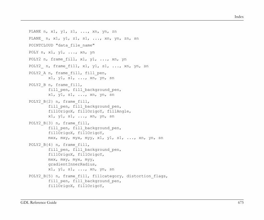
Index
GDL Reference Guide 675
PLANE n, x1, y1, z1, ..., xn, yn, zn
PLANE_ n, x1, y1, z1, s1, ..., xn, yn, zn, sn
POINTCLOUD "data_file_name"
POLY n, x1, y1, ..., xn, yn
POLY2 n, frame_fill, x1, y1, ..., xn, yn
POLY2_ n, frame_fill, x1, y1, s1, ..., xn, yn, sn
POLY2_A n, frame_fill, fill_pen, x1, y1, s1, ..., xn, yn, sn
POLY2_B n, frame_fill, fill_pen, fill_background_pen, x1, y1, s1, ..., xn, yn, sn
POLY2_B{2} n, frame_fill, fill_pen, fill_background_pen, fillOrigoX, fillOrigoY, fillAngle, x1, y1, s1, ..., xn, yn, sn
POLY2_B{3} n, frame_fill, fill_pen, fill_background_pen, fillOrigoX, fillOrigoY, mxx, mxy, myx, myy, x1, y1, s1, ..., xn, yn, sn
POLY2_B{4} n, frame_fill, fill_pen, fill_background_pen, fillOrigoX, fillOrigoY, mxx, mxy, myx, myy, gradientInnerRadius, x1, y1, s1, ..., xn, yn, sn
POLY2_B{5} n, frame_fill, fillcategory, distortion_flags, fill_pen, fill_background_pen, fillOrigoX, fillOrigoY,

Index
GDL Reference Guide 676
mxx, mxy, myx, myy, gradientInnerRadius, x1, y1, s1, ..., xn, yn, sn
POLY2_B{6} n, frame_fill, fillcategory, distortion_flags, fill_pen, fill_background_pen, fillOrigoX, fillOrigoY, mxx, mxy, myx, myy, gradientInnerRadius, x1, y1, s1, pen1, linetype1, ..., xn, yn, sn, penn, linetypen
POLYROOF defaultMat, k, m, n, offset, thickness, applyContourInsidePivot, z_1, ..., z_k, pivotX_1, pivotY_1, pivotMask_1, roofAngle_11, gableOverhang_11, topMat_11, bottomMat_11, ... roofAngle_1k, gableOverhang_1k, topMat_1k, bottomMat_1k, ... pivotX_m, pivotY_m, pivotMask_m, roofAngle_m1, gableOverhang_m1, topMat_m1, bottomMat_m1, ... roofAngle_mk, gableOverhang_mk, topMat_mk, bottomMat_mk, contourX_1, contourY_1, contourMask_1, edgeTrim_1, edgeAngle_1, edgeMat_1, ... contourX_n, contourY_n, contourMask_n, edgeTrim_n, edgeAngle_n, edgeMat_n
POLYROOF{2} defaultMat, k, m, n, offset, thickness, totalThickness, applyContourInsidePivot, z_1, ..., z_k, pivotX_1, pivotY_1, pivotMask_1, roofAngle_11, gableOverhang_11, topMat_11, bottomMat_11, ... roofAngle_1k, gableOverhang_1k, topMat_1k, bottomMat_1k,

Index
GDL Reference Guide 677
... pivotX_m, pivotY_m, pivotMask_m, roofAngle_m1, gableOverhang_m1, topMat_m1, bottomMat_m1, ... roofAngle_mk, gableOverhang_mk, topMat_mk, bottomMat_mk, contourX_1, contourY_1, contourMask_1, edgeTrim_1, edgeAngle_1, edgeMat_1, ... contourX_n, contourY_n, contourMask_n, edgeTrim_n, edgeAngle_n, edgeMat_n
POLYROOF{3} defaultMat, mask, k, m, n, offset, thickness, totalThickness, applyContourInsidePivot, z_1, ..., z_k, pivotX_1, pivotY_1, pivotMask_1, roofAngle_11, gableOverhang_11, topMat_11, bottomMat_11, ... roofAngle_1k, gableOverhang_1k, topMat_1k, bottomMat_1k, ... pivotX_m, pivotY_m, pivotMask_m, roofAngle_m1, gableOverhang_m1, topMat_m1, bottomMat_m1, ... roofAngle_mk, gableOverhang_mk, topMat_mk, bottomMat_mk, contourX_1, contourY_1, contourMask_1, edgeTrim_1, edgeAngle_1, edgeMat_1, ... contourX_n, contourY_n, contourMask_n, edgeTrim_n, edgeAngle_n, edgeMat_n
POLYROOF{4} defaultMat, mask, k, m, n, offset, thickness, totalThickness, applyContourInsidePivot, z_1, ..., z_k, pivotX_1, pivotY_1, pivotMask_1, roofAngle_11, gableOverhang_11, topMat_11, bottomMat_11, ... roofAngle_1k, gableOverhang_1k, topMat_1k, bottomMat_1k, ... pivotX_m, pivotY_m, pivotMask_m,
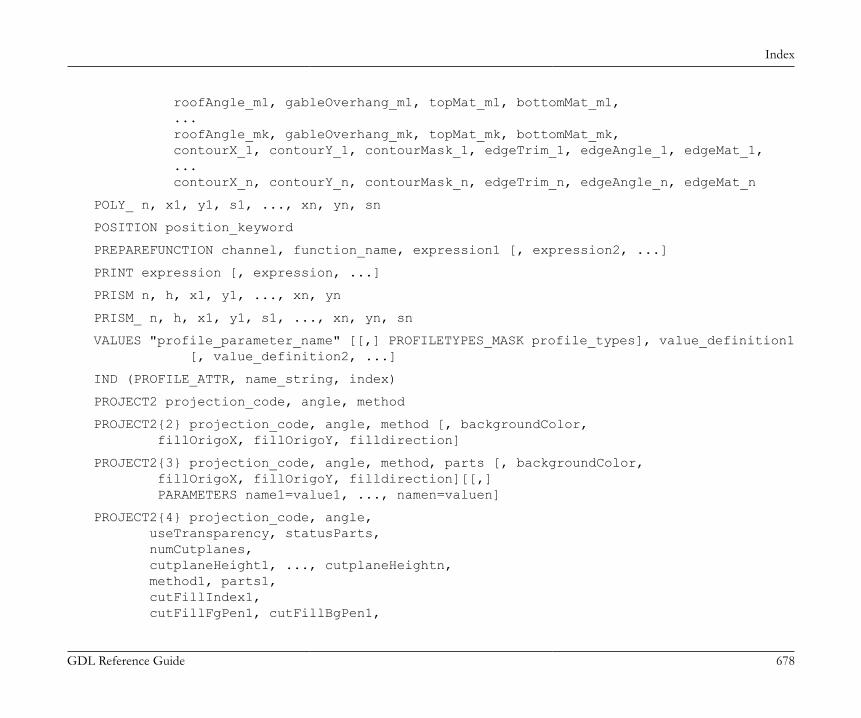
Index
GDL Reference Guide 678
roofAngle_m1, gableOverhang_m1, topMat_m1, bottomMat_m1, ... roofAngle_mk, gableOverhang_mk, topMat_mk, bottomMat_mk, contourX_1, contourY_1, contourMask_1, edgeTrim_1, edgeAngle_1, edgeMat_1, ... contourX_n, contourY_n, contourMask_n, edgeTrim_n, edgeAngle_n, edgeMat_n
POLY_ n, x1, y1, s1, ..., xn, yn, sn
POSITION position_keyword
PREPAREFUNCTION channel, function_name, expression1 [, expression2, ...]
PRINT expression [, expression, ...]
PRISM n, h, x1, y1, ..., xn, yn
PRISM_ n, h, x1, y1, s1, ..., xn, yn, sn
VALUES "profile_parameter_name" [[,] PROFILETYPES_MASK profile_types], value_definition1 [, value_definition2, ...]
IND (PROFILE_ATTR, name_string, index)
PROJECT2 projection_code, angle, method
PROJECT2{2} projection_code, angle, method [, backgroundColor, fillOrigoX, fillOrigoY, filldirection]
PROJECT2{3} projection_code, angle, method, parts [, backgroundColor, fillOrigoX, fillOrigoY, filldirection][[,] PARAMETERS name1=value1, ..., namen=valuen]
PROJECT2{4} projection_code, angle, useTransparency, statusParts, numCutplanes, cutplaneHeight1, ..., cutplaneHeightn, method1, parts1, cutFillIndex1, cutFillFgPen1, cutFillBgPen1,

Index
GDL Reference Guide 679
cutFillOrigoX1, cutFillOrigoY1, cutFillDirection1, cutLinePen1, cutLineType1, projectedFillIndex1, projectedFillFgPen1, projectedFillBgPen1, projectedFillOrigoX1, projectedFillOrigoY1, projectedFillDirection1, projectedLinePen1, projectedLineType1, ... method(numCutplanes+1)), parts(numCutplanes+1), cutFillIndex(numCutplanes+1), cutFillFgPen(numCutplanes+1), cutFillBgPen(numCutplanes+1), cutFillOrigoX(numCutplanes+1), cutFillOrigoY(numCutplanes+1), cutFillDirection(numCutplanes+1), cutLinePen(numCutplanes+1), cutLineType(numCutplanes+1), projectedFillIndex(numCutplanes+1), projectedFillFgPen(numCutplanes+1), projectedFillBgPen(numCutplanes+1), projectedFillOrigoX(numCutplanes+1), projectedFillOrigoY(numCutplanes+1), projectedFillDirection(numCutplanes+1), projectedLinePen(numCutplanes+1), projectedLineType(numCutplanes+1)
PUT expression [, expression, ...]
PYRAMID n, h, mask, x1, y1, s1, ..., xn, yn, sn
RRADIUS radius_min, radius_max
RECT a, b
RECT2 x1, y1, x2, y2
REF COMPONENT code [, keycode [, numeric_expression]]
REF DESCRIPTOR code [, keycode]
REMOVEKEY (dictionary.key)

Index
GDL Reference Guide 680
REPEAT [statement1 statement2 ... statementn]UNTIL condition
REQ (parameter_string)
REQUEST (question_name, name | index, variable1 [, variable2, ...])
RESOL n
RETURN
CALL macro_name_string [,] PARAMETERS [ALL][name1=value1, ..., namen=valuen][[,] RETURNED_PARAMETERS r1, r2, ...]
REVOLVE n, alpha, mask, x1, y1, s1, ..., xn, yn, sn
REVOLVEDSHELL topMat, bottomMat, sideMat_1, sideMat_2, sideMat_3, sideMat_4, defaultMat, n, offset, thickness, flipped, trimmingBody, alphaOffset, alpha, preThickenTran_11, preThickenTran_12, preThickenTran_13, preThickenTran_14, preThickenTran_21, preThickenTran_22, preThickenTran_23, preThickenTran_24, preThickenTran_31, preThickenTran_32, preThickenTran_33, preThickenTran_34, x_1, y_1, s_1, ... x_n, y_n, s_n
REVOLVEDSHELLANGULAR topMat, bottomMat, sideMat_1, sideMat_2, sideMat_3, sideMat_4, defaultMat, n, offset, thickness, flipped, trimmingBody, alphaOffset, alpha, segmentationType, nOfSegments, preThickenTran_11, preThickenTran_12, preThickenTran_13, preThickenTran_14, preThickenTran_21, preThickenTran_22, preThickenTran_23,

Index
GDL Reference Guide 681
preThickenTran_24, preThickenTran_31, preThickenTran_32, preThickenTran_33, preThickenTran_34, x_1, y_1, s_1, ... x_n, y_n, s_n
REVOLVEDSHELLANGULAR{2} topMat, bottomMat, sideMat_1, sideMat_2, sideMat_3, sideMat_4, defaultMat, n, status, offset, thickness, flipped, trimmingBody, alphaOffset, alpha, segmentationType, nOfSegments, preThickenTran_11, preThickenTran_12, preThickenTran_13, preThickenTran_14, preThickenTran_21, preThickenTran_22, preThickenTran_23, preThickenTran_24, preThickenTran_31, preThickenTran_32, preThickenTran_33, preThickenTran_34, x_1, y_1, s_1, ... x_n, y_n, s_n
REVOLVEDSHELLANGULAR{3} topMat, bottomMat, sideMat_1, sideMat_2, sideMat_3, sideMat_4, defaultMat, n, status, offset, thickness, flipped, trimmingBody, alphaOffset, alpha, segmentationType, nOfSegments, preThickenTran_11, preThickenTran_12, preThickenTran_13, preThickenTran_14, preThickenTran_21, preThickenTran_22, preThickenTran_23, preThickenTran_24, preThickenTran_31, preThickenTran_32, preThickenTran_33, preThickenTran_34, x_1, y_1, s_1, ... x_n, y_n, s_n

Index
GDL Reference Guide 682
REVOLVEDSHELL{2} topMat, bottomMat, sideMat_1, sideMat_2, sideMat_3, sideMat_4, defaultMat, n, status, offset, thickness, flipped, trimmingBody, alphaOffset, alpha, preThickenTran_11, preThickenTran_12, preThickenTran_13, preThickenTran_14, preThickenTran_21, preThickenTran_22, preThickenTran_23, preThickenTran_24, preThickenTran_31, preThickenTran_32, preThickenTran_33, preThickenTran_34, x_1, y_1, s_1, ... x_n, y_n, s_n
REVOLVEDSHELL{3} topMat, bottomMat, sideMat_1, sideMat_2, sideMat_3, sideMat_4, defaultMat, n, status, offset, thickness, flipped, trimmingBody, alphaOffset, alpha, preThickenTran_11, preThickenTran_12, preThickenTran_13, preThickenTran_14, preThickenTran_21, preThickenTran_22, preThickenTran_23, preThickenTran_24, preThickenTran_31, preThickenTran_32, preThickenTran_33, preThickenTran_34, x_1, y_1, s_1, ... x_n, y_n, s_n
REVOLVE{2} n, alphaOffset, alpha, mask, sideMat, x1, y1, s1, mat1, ..., xn, yn, sn, matn
REVOLVE{3} n, alphaOffset, alpha, betaOffset, beta, mask, sideMat, x1, y1, s1, mat1, ..., xn, yn, sn, matn
REVOLVE{4} n, alphaOffset, alpha, betaOffset, beta, mask, sideMat, x1, y1, s1, mat1, ..., xn, yn, sn, matn
REVOLVE{5}n, alphaOffset, alpha, betaOffset, beta, mask, sideMat, x1, y1, s1, mat1, ..., xn, yn, sn, matn
RICHTEXT x, y, height, 0, textblock_name
RICHTEXT2 x, y, textblock_name
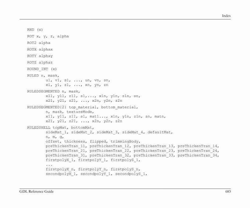
Index
GDL Reference Guide 683
RND (x)
ROT x, y, z, alpha
ROT2 alpha
ROTX alphax
ROTY alphay
ROTZ alphaz
ROUND_INT (x)
RULED n, mask, u1, v1, s1, ..., un, vn, sn, x1, y1, z1, ..., xn, yn, zn
RULEDSEGMENTED n, mask, x11, y11, z11, s1,..., x1n, y1n, z1n, sn, x21, y21, z21, ..., x2n, y2n, z2n
RULEDSEGMENTED{2} top_material, bottom_material, n, mask, textureMode, x11, y11, z11, s1, mat1..., x1n, y1n, z1n, sn, matn, x21, y21, z21, ..., x2n, y2n, z2n
RULEDSHELL topMat, bottomMat, sideMat_1, sideMat_2, sideMat_3, sideMat_4, defaultMat, n, m, g, offset, thickness, flipped, trimmingBody, preThickenTran_11, preThickenTran_12, preThickenTran_13, preThickenTran_14, preThickenTran_21, preThickenTran_22, preThickenTran_23, preThickenTran_24, preThickenTran_31, preThickenTran_32, preThickenTran_33, preThickenTran_34, firstpolyX_1, firstpolyY_1, firstpolyS_1, ... firstpolyX_n, firstpolyY_n, firstpolyS_n, secondpolyX_1, secondpolyY_1, secondpolyS_1,
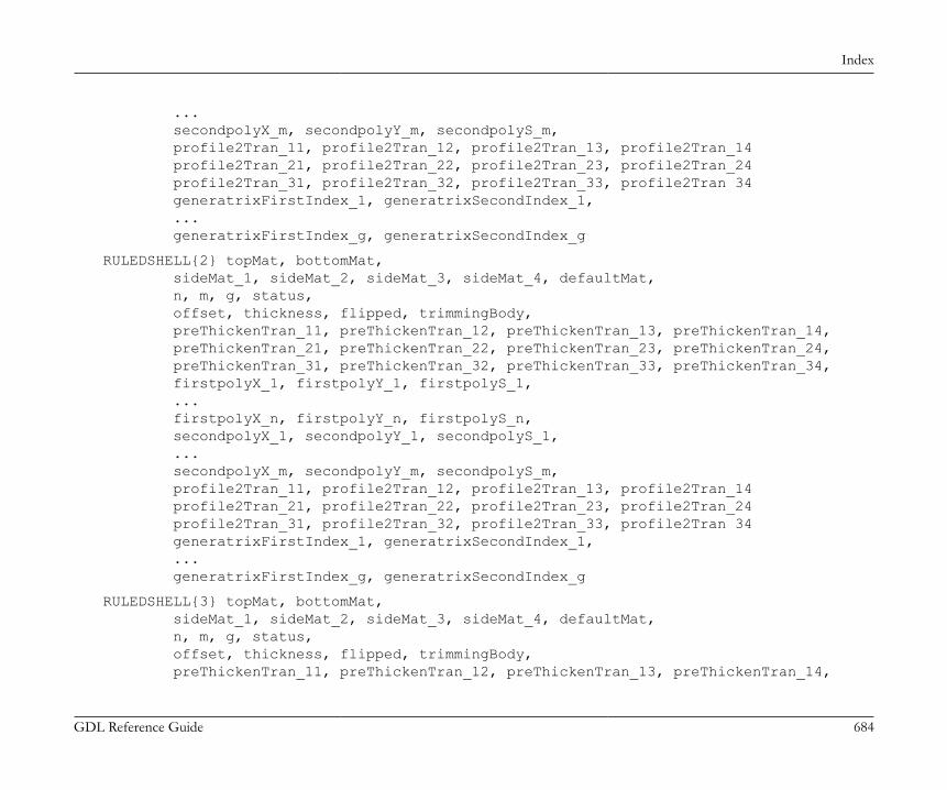
Index
GDL Reference Guide 684
... secondpolyX_m, secondpolyY_m, secondpolyS_m, profile2Tran_11, profile2Tran_12, profile2Tran_13, profile2Tran_14 profile2Tran_21, profile2Tran_22, profile2Tran_23, profile2Tran_24 profile2Tran_31, profile2Tran_32, profile2Tran_33, profile2Tran 34 generatrixFirstIndex_1, generatrixSecondIndex_1, ... generatrixFirstIndex_g, generatrixSecondIndex_g
RULEDSHELL{2} topMat, bottomMat, sideMat_1, sideMat_2, sideMat_3, sideMat_4, defaultMat, n, m, g, status, offset, thickness, flipped, trimmingBody, preThickenTran_11, preThickenTran_12, preThickenTran_13, preThickenTran_14, preThickenTran_21, preThickenTran_22, preThickenTran_23, preThickenTran_24, preThickenTran_31, preThickenTran_32, preThickenTran_33, preThickenTran_34, firstpolyX_1, firstpolyY_1, firstpolyS_1, ... firstpolyX_n, firstpolyY_n, firstpolyS_n, secondpolyX_1, secondpolyY_1, secondpolyS_1, ... secondpolyX_m, secondpolyY_m, secondpolyS_m, profile2Tran_11, profile2Tran_12, profile2Tran_13, profile2Tran_14 profile2Tran_21, profile2Tran_22, profile2Tran_23, profile2Tran_24 profile2Tran_31, profile2Tran_32, profile2Tran_33, profile2Tran 34 generatrixFirstIndex_1, generatrixSecondIndex_1, ... generatrixFirstIndex_g, generatrixSecondIndex_g
RULEDSHELL{3} topMat, bottomMat, sideMat_1, sideMat_2, sideMat_3, sideMat_4, defaultMat, n, m, g, status, offset, thickness, flipped, trimmingBody, preThickenTran_11, preThickenTran_12, preThickenTran_13, preThickenTran_14,
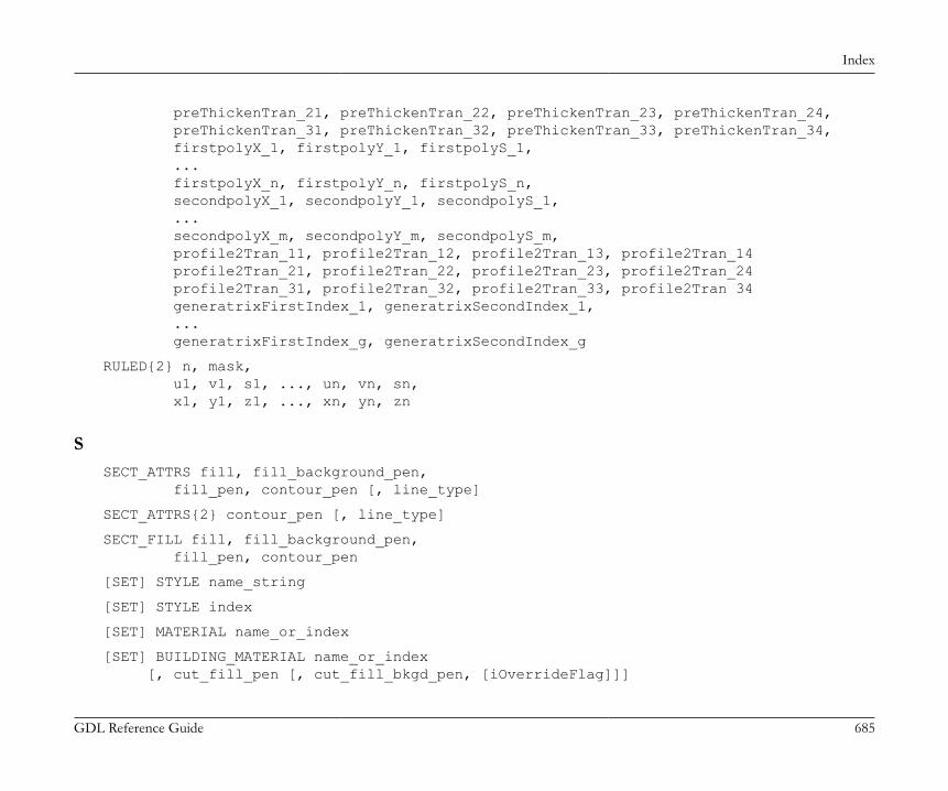
Index
GDL Reference Guide 685
preThickenTran_21, preThickenTran_22, preThickenTran_23, preThickenTran_24, preThickenTran_31, preThickenTran_32, preThickenTran_33, preThickenTran_34, firstpolyX_1, firstpolyY_1, firstpolyS_1, ... firstpolyX_n, firstpolyY_n, firstpolyS_n, secondpolyX_1, secondpolyY_1, secondpolyS_1, ... secondpolyX_m, secondpolyY_m, secondpolyS_m, profile2Tran_11, profile2Tran_12, profile2Tran_13, profile2Tran_14 profile2Tran_21, profile2Tran_22, profile2Tran_23, profile2Tran_24 profile2Tran_31, profile2Tran_32, profile2Tran_33, profile2Tran 34 generatrixFirstIndex_1, generatrixSecondIndex_1, ... generatrixFirstIndex_g, generatrixSecondIndex_g
RULED{2} n, mask, u1, v1, s1, ..., un, vn, sn, x1, y1, z1, ..., xn, yn, zn
SSECT_ATTRS fill, fill_background_pen, fill_pen, contour_pen [, line_type]
SECT_ATTRS{2} contour_pen [, line_type]
SECT_FILL fill, fill_background_pen, fill_pen, contour_pen
[SET] STYLE name_string
[SET] STYLE index
[SET] MATERIAL name_or_index
[SET] BUILDING_MATERIAL name_or_index [, cut_fill_pen [, cut_fill_bkgd_pen, [iOverrideFlag]]]
Index
GDL Reference Guide 686
[SET] FILL name_string
[SET] FILL index
[SET] LINE_TYPE name_string
[SET] LINE_TYPE index
SETMIGRATIONGUID guid
SGN (x)
SHADOW casting [, catching]
SIN (x)
SLAB n, h, x1, y1, z1, ..., xn, yn, zn
SLAB_ n, h, x1, y1, z1, s1, ..., xn, yn, zn, sn
MODEL SOLID
SPHERE r
SPLINE2 n, status, x1, y1, angle1, ..., xn, yn, anglen
SPLINE2A n, status, x1, y1, angle1, length_previous1, length_next1, ... xn, yn, anglen, length_previousn, length_nextn
SPLIT (string, format, variable1 [, variable2, ..., variablen])
SPRISM_ top_material, bottom_material, side_material, n, xb, yb, xe, ye, h, angle, x1, y1, s1, ... xn, yn, sn
SPRISM_{2} top_material, bottom_material, side_material, n,

Index
GDL Reference Guide 687
xtb, ytb, xte, yte, topz, tangle, xbb, ybb, xbe, ybe, bottomz, bangle, x1, y1, s1, mat1, ... xn, yn, sn, matn
SPRISM_{3} top_material, bottom_material, side_material, mask, n, xtb, ytb, xte, yte, topz, tangle, xbb, ybb, xbe, ybe, bottomz, bangle, x1, y1, s1, mat1, ... xn, yn, sn, matn
SPRISM_{4} top_material, bottom_material, side_material, mask, n, xtb, ytb, xte, yte, topz, tangle, xbb, ybb, xbe, ybe, bottomz, bangle, x1, y1, s1, mat1, ... xn, yn, sn, matn
SQR (x)
FOR variable_name = initial_value TO end_value [ STEP step_value ] NEXT variable_name
STORED_PAR_VALUE ("oldparname", outputvalue)
STR (numeric_expression, length, fractions)
STR (format_string, numeric_expression)
STRLEN (string_expression)
STRSTR (string_expression1, string_expression2[, case_insensitivity])
STRSUB (string_expression, start_position, characters_number)
STRTOLOWER (string_expression)
Index
GDL Reference Guide 688
STRTOUPPER (string_expression)
STR{2} (format_string, numeric_expression [, extra_accuracy_string])
STW (string_expression)
[SET] STYLE name_string
[SET] STYLE index
IND (STYLE, name_string)
SUBGROUP (g_expr1, g_expr2)
SUBGROUP{2} (g_expr1, g_expr2, edgeColor, materialId, materialColor [, operationStatus])
SUBGROUP{3} (g_expr1, g_expr2, edgeColor, materialId, materialColor [, operationStatus])
MODEL SURFACE
SURFACE3D ()
SWEEP n, m, alpha, scale, mask, u1, v1, s1, ..., un, vn, sn, x1, y1, z1, ..., xm, ym, zm
SWEEPGROUP (g_expr, x, y, z)
SWEEPGROUP{2} (g_expr, x, y, z)
SWEEPGROUP{3} (g_expr, x, y, z, edgeColor, materialId, materialColor, method)
SWEEPGROUP{4} (g_expr, x, y, z, edgeColor, materialId, materialColor, method, status)
SWEEPGROUP{5} (g_expr, x, y, z, edgeColor, materialId, materialColor, method, status)
TTAN (x)
TEVE x, y, z, u, v
TEXT d, 0, expression

Index
GDL Reference Guide 689
TEXT2 x, y, expression
TEXTBLOCK name width, anchor, angle, width_factor, charspace_factor, fixed_height, 'string_expr1' [, 'string_expr2', ...]
TEXTBLOCK_ name width, anchor, angle, width_factor, charspace_factor, fixed_height, n, 'expr_1' [, 'expr_2', ..., 'expr_n']
IND (TEXTURE, name_string)
IF condition THEN labelIF condition GOTO labelIF condition GOSUB label
IF condition THEN statement [ELSE statement]
IF condition THEN [statement1 statement2 ... statementn][ELSE statementn+1 statementn+2 ... statementn+m]ENDIF
FOR variable_name = initial_value TO end_value [ STEP step_value ] NEXT variable_name
TOLER d
DEL TOP
TUBE n, m, mask, u1, w1, s1, ... un, wn, sn,
Index
GDL Reference Guide 690
x1, y1, z1, angle1, ... xm, ym, zm, anglem
TUBEA n, m, mask, u1, w1, s1, ... un, wn, sn, x1, y1, z1, ... xm, ym, zm
TUBE{2} top_material, bottom_material, cut_material, n, m, mask, u1, w1, s1, mat1, ... un, wn, sn, matn, x1, y1, z1, angle1, ... xm, ym, zm, anglem
UUI_BUTTON type, text, x, y [, width, height, id [, url]]
UI_BUTTON type, text, x, y, width, height [, id [, url]] [ UI_TOOLTIP tooltiptext ]
UI_COLORPICKER "redParamName", "greenParamName", "blueParamName", x0, y0 [, width [, height]]
UI_COLORPICKER{2} redParamName, greenParamName, blueParamName, x0, y0 [, width [, height]]
UI_CURRENT_PAGE index
UI_CUSTOM_POPUP_INFIELD "name", x, y, width, height, storeHiddenId, treeDepth, groupingMethod, selectedValDescription,
Index
GDL Reference Guide 691
value1, value2, valuesArray1, .... valuen, valuesArrayn
UI_CUSTOM_POPUP_INFIELD "name", x, y, width, height , extra parameters ... [ UI_TOOLTIP tooltiptext ]
UI_CUSTOM_POPUP_INFIELD{2} name, x, y, width, height, storeHiddenId, treeDepth, groupingMethod, selectedValDescription, value1, value2, valuesArray1, .... valuen, valuesArrayn
UI_CUSTOM_POPUP_INFIELD{2} name, x, y, width, height , extra parameters ... [ UI_TOOLTIP tooltiptext ]
UI_CUSTOM_POPUP_LISTITEM itemID, fieldID, "name", childFlag, image, paramDesc, storeHiddenId, treeDepth, groupingMethod, selectedValDescription, value1, value2, valuesArray1, .... valuen, valuesArrayn
UI_CUSTOM_POPUP_LISTITEM itemID, fieldID, "name", childFlag , image , paramDesc, extra parameters ... [ UI_TOOLTIP tooltiptext ]
UI_CUSTOM_POPUP_LISTITEM{2} itemID, fieldID, name, childFlag, image, paramDesc, storeHiddenId, treeDepth, groupingMethod, selectedValDescription, value1, value2, valuesArray1, .... valuen, valuesArrayn
UI_CUSTOM_POPUP_LISTITEM{2} itemID, fieldID, name, childFlag , image , paramDesc, extra parameters ... [ UI_TOOLTIP tooltiptext ]
UI_DIALOG title [, size_x, size_y]
UI_GROUPBOX text, x, y, width, height
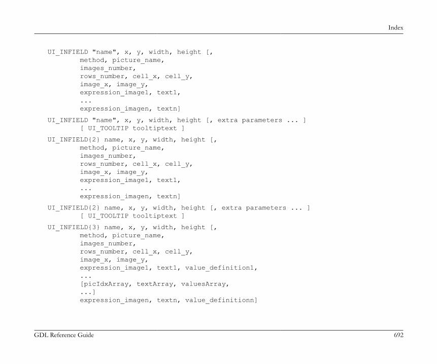
Index
GDL Reference Guide 692
UI_INFIELD "name", x, y, width, height [, method, picture_name, images_number, rows_number, cell_x, cell_y, image_x, image_y, expression_image1, text1, ... expression_imagen, textn]
UI_INFIELD "name", x, y, width, height [, extra parameters ... ] [ UI_TOOLTIP tooltiptext ]
UI_INFIELD{2} name, x, y, width, height [, method, picture_name, images_number, rows_number, cell_x, cell_y, image_x, image_y, expression_image1, text1, ... expression_imagen, textn]
UI_INFIELD{2} name, x, y, width, height [, extra parameters ... ] [ UI_TOOLTIP tooltiptext ]
UI_INFIELD{3} name, x, y, width, height [, method, picture_name, images_number, rows_number, cell_x, cell_y, image_x, image_y, expression_image1, text1, value_definition1, ... [picIdxArray, textArray, valuesArray, ...] expression_imagen, textn, value_definitionn]

Index
GDL Reference Guide 693
UI_INFIELD{3} name, x, y, width, height [, extra parameters ... ] [ UI_TOOLTIP tooltiptext ]
UI_INFIELD{4} "name", x, y, width, height [, method, picture_name, images_number, rows_number, cell_x, cell_y, image_x, image_y, expression_image1, text1, value_definition1, ... [picIdxArray, textArray, valuesArray, ...] expression_imagen, textn, value_definitionn]
UI_INFIELD{4} "name", x, y, width, height [, extra parameters ... ] [ UI_TOOLTIP tooltiptext ]
UI_LISTFIELD fieldID, x, y, width, height [, iconFlag [, description_header [, value_header]]]
UI_LISTFIELD fieldID, x, y, width, height [, iconFlag [, description_header [, value_header]]] [ UI_TOOLTIP tooltiptext ]
UI_LISTITEM itemID, fieldID, "name" [, childFlag [, image [, paramDesc]]]
UI_LISTITEM itemID, fieldID, "name" [, childFlag [, image [, paramDesc]]] [ UI_TOOLTIP tooltiptext ]
UI_LISTITEM{2} itemID, fieldID, name [, childFlag [, image [, paramDesc]]]
UI_LISTITEM{2} itemID, fieldID, name [, childFlag [, image [, paramDesc]]] [ UI_TOOLTIP tooltiptext ]
UI_OUTFIELD expression, x, y [, width, height [, flags]]
UI_OUTFIELD expression, x, y, width, height [, flags] [ UI_TOOLTIP tooltiptext ]
UI_PAGE page_number [, parent_id, page_title [, image]]

Index
GDL Reference Guide 694
UI_PICT picture_reference, x, y [, width, height [, mask]]
UI_PICT expression, x, y [, width, height [, mask]] [ UI_TOOLTIP tooltiptext ]
UI_PICT_BUTTON type, text, picture_reference, x, y, width, height [, id [, url]]
UI_PICT_BUTTON type, text, picture_reference, x, y, width, height [, id [, url]] [ UI_TOOLTIP tooltiptext ]
UI_PICT_PUSHCHECKBUTTON name, text, picture_reference, frameFlag, x, y, width, height [UI_TOOLTIP tooltip]
UI_PICT_PUSHCHECKBUTTON{2} "name", text, picture_reference, frameFlag, x, y, width, height [UI_TOOLTIP tooltip]
UI_PICT_RADIOBUTTON name, value, text, picture_reference, x, y, width, height [UI_TOOLTIP tooltip]
UI_PICT_RADIOBUTTON{2} "name", value, text, picture_reference, x, y, width, height [UI_TOOLTIP tooltip]
UI_RADIOBUTTON name, value, text, x, y, width, height
UI_RADIOBUTTON name, value, text, x, y, width, height [ UI_TOOLTIP tooltiptext ]
UI_RADIOBUTTON{2} "name", value, text, x, y, width, height
UI_SEPARATOR x1, y1, x2, y2
UI_SLIDER "name", x0, y0, width, height [, nSegments [, sliderStyle]]
UI_SLIDER{2} name, x0, y0, width, height [, nSegments [, sliderStyle]]
UI_STYLE fontsize, face_code
UI_TEXTSTYLE_INFIELD name, faceCodeMask, x, y, buttonWidth, buttonHeight[, buttonOffsetX]
UI_TEXTSTYLE_INFIELD{2} "name", faceCodeMask, x, y, buttonWidth, buttonHeight [, buttonOffsetX]
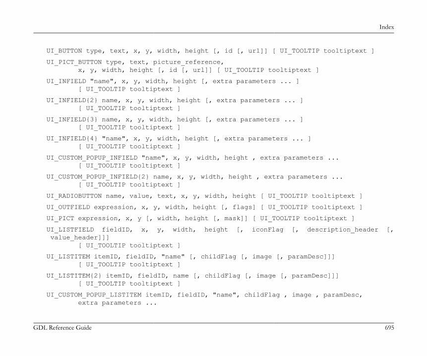
Index
GDL Reference Guide 695
UI_BUTTON type, text, x, y, width, height [, id [, url]] [ UI_TOOLTIP tooltiptext ]
UI_PICT_BUTTON type, text, picture_reference, x, y, width, height [, id [, url]] [ UI_TOOLTIP tooltiptext ]
UI_INFIELD "name", x, y, width, height [, extra parameters ... ] [ UI_TOOLTIP tooltiptext ]
UI_INFIELD{2} name, x, y, width, height [, extra parameters ... ] [ UI_TOOLTIP tooltiptext ]
UI_INFIELD{3} name, x, y, width, height [, extra parameters ... ] [ UI_TOOLTIP tooltiptext ]
UI_INFIELD{4} "name", x, y, width, height [, extra parameters ... ] [ UI_TOOLTIP tooltiptext ]
UI_CUSTOM_POPUP_INFIELD "name", x, y, width, height , extra parameters ... [ UI_TOOLTIP tooltiptext ]
UI_CUSTOM_POPUP_INFIELD{2} name, x, y, width, height , extra parameters ... [ UI_TOOLTIP tooltiptext ]
UI_RADIOBUTTON name, value, text, x, y, width, height [ UI_TOOLTIP tooltiptext ]
UI_OUTFIELD expression, x, y, width, height [, flags] [ UI_TOOLTIP tooltiptext ]
UI_PICT expression, x, y [, width, height [, mask]] [ UI_TOOLTIP tooltiptext ]
UI_LISTFIELD fieldID, x, y, width, height [, iconFlag [, description_header [, value_header]]] [ UI_TOOLTIP tooltiptext ]
UI_LISTITEM itemID, fieldID, "name" [, childFlag [, image [, paramDesc]]] [ UI_TOOLTIP tooltiptext ]
UI_LISTITEM{2} itemID, fieldID, name [, childFlag [, image [, paramDesc]]] [ UI_TOOLTIP tooltiptext ]
UI_CUSTOM_POPUP_LISTITEM itemID, fieldID, "name", childFlag , image , paramDesc, extra parameters ...
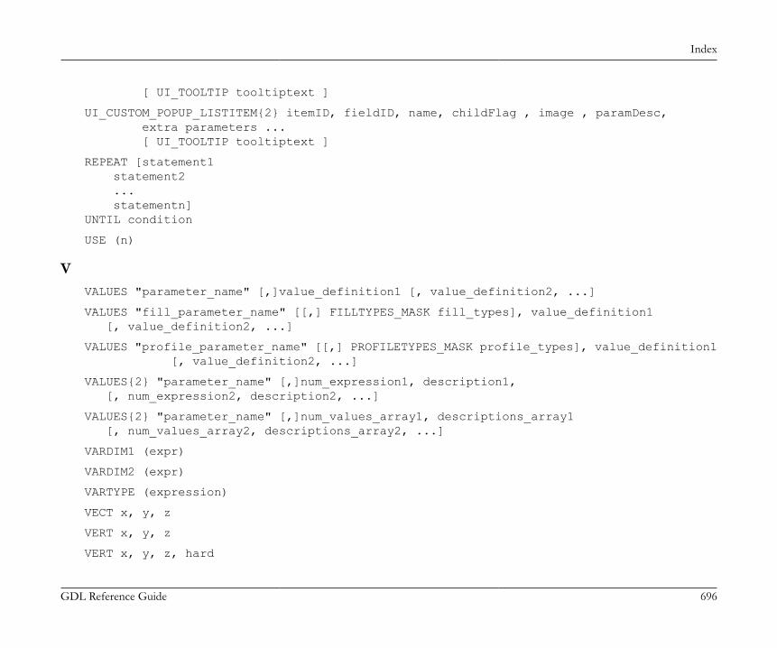
Index
GDL Reference Guide 696
[ UI_TOOLTIP tooltiptext ]
UI_CUSTOM_POPUP_LISTITEM{2} itemID, fieldID, name, childFlag , image , paramDesc, extra parameters ... [ UI_TOOLTIP tooltiptext ]
REPEAT [statement1 statement2 ... statementn]UNTIL condition
USE (n)
VVALUES "parameter_name" [,]value_definition1 [, value_definition2, ...]
VALUES "fill_parameter_name" [[,] FILLTYPES_MASK fill_types], value_definition1 [, value_definition2, ...]
VALUES "profile_parameter_name" [[,] PROFILETYPES_MASK profile_types], value_definition1 [, value_definition2, ...]
VALUES{2} "parameter_name" [,]num_expression1, description1, [, num_expression2, description2, ...]
VALUES{2} "parameter_name" [,]num_values_array1, descriptions_array1 [, num_values_array2, descriptions_array2, ...]
VARDIM1 (expr)
VARDIM2 (expr)
VARTYPE (expression)
VECT x, y, z
VERT x, y, z
VERT x, y, z, hard

Index
GDL Reference Guide 697
VOLUME3D ()
WWALLARC2 x, y, r, alpha, beta
WALLBLOCK2 n, fill_control, fill_pen, fill_background_pen, fillOrigoX, fillOrigoY, fillAngle, x1, y1, s1, ... xn, yn, sn
WALLBLOCK2{2} n, frame_fill, fillcategory, distortion_flags, fill_pen, fill_background_pen, fillOrigoX, fillOrigoY, mxx, mxy, myx, myy, innerRadius, x1, y1, s1, ... xn, yn, sn
WALLHOLE n, status, x1, y1, mask1, ... xn, yn, maskn [, x, y, z]
WALLHOLE2 n, fill_control, fill_pen, fill_background_pen, fillOrigoX, fillOrigoY, fillAngle, x1, y1, s1, ... xn, yn, sn
WALLHOLE2{2} n, frame_fill, fillcategory, distortion_flags, fill_pen, fill_background_pen, fillOrigoX, fillOrigoY,

Index
GDL Reference Guide 698
mxx, mxy, myx, myy, innerRadius, x1, y1, s1, ... xn, yn, sn
WALLLINE2 x1, y1, x2, y2
WALLNICHE n, method, status, rx, ry, rz, d, x1, y1, mask1, [mat1,] ... xn, yn, maskn[, matn]
DO [statment1 statement2 ... statementn]WHILE condition
WHILE condition DO [statement1 statement2 ... statementn]ENDWHILE
MODEL WIRE
XXFORM newx_x, newy_x, newz_x, offset_x, newx_y, newy_y, newz_y, offset_y, newx_z, newy_z, newz_z, offset_z
XWALL_ left_material, right_material, vertical_material, horizontal_material,
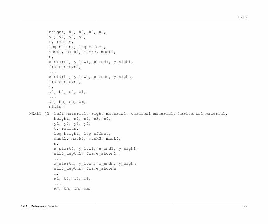
Index
GDL Reference Guide 699
height, x1, x2, x3, x4, y1, y2, y3, y4, t, radius, log_height, log_offset, mask1, mask2, mask3, mask4, n, x_start1, y_low1, x_end1, y_high1, frame_shown1, ... x_startn, y_lown, x_endn, y_highn, frame_shownn, m, a1, b1, c1, d1, ... am, bm, cm, dm, status
XWALL_{2} left_material, right_material, vertical_material, horizontal_material, height, x1, x2, x3, x4, y1, y2, y3, y4, t, radius, log_height, log_offset, mask1, mask2, mask3, mask4, n, x_start1, y_low1, x_end1, y_high1, sill_depth1, frame_shown1, ... x_startn, y_lown, x_endn, y_highn, sill_depthn, frame_shownn, m, a1, b1, c1, d1, ... am, bm, cm, dm,

Index
GDL Reference Guide 700
status
XWALL_{3} left_material, right_material, vertical_material, horizontal_material, height, x1, x2, x3, x4, y1, y2, y3, y4, t, radius, log_height, log_offset, mask1, mask2, mask3, mask4, n, x_start1, y_low1, x_end1, y_high1, sill_depth1, frame_shown1, ... x_startn, y_lown, x_endn, y_highn, sill_depthn, frame_shownn, m, a1, b1, c1, d1, ... am, bm, cm, dm, status


