176
GE Fanuc Automation Computer Numerical Control Products DNC 2 Descriptions Manual GFZ-61992E/02 October 1997
GE Fanuc Automation
Computer Numerical Control Products
DNC 2
Descriptions Manual
GFZ-61992E/02 October 1997
GFL-001
Warnings, Cautions, and Notesas Used in this Publication
Warning
Warning notices are used in this publication to emphasize that hazardous voltages, currents,temperatures, or other conditions that could cause personal injury exist in this equipment ormay be associated with its use.
In situations where inattention could cause either personal injury or damage to equipment, aWarning notice is used.
Caution
Caution notices are used where equipment might be damaged if care is not taken.
NoteNotes merely call attention to information that is especially significant to understanding andoperating the equipment.
This document is based on information available at the time of its publication. While effortshave been made to be accurate, the information contained herein does not purport to cover alldetails or variations in hardware or software, nor to provide for every possible contingency inconnection with installation, operation, or maintenance. Features may be described hereinwhich are not present in all hardware and software systems. GE Fanuc Automation assumesno obligation of notice to holders of this document with respect to changes subsequently made.
GE Fanuc Automation makes no representation or warranty, expressed, implied, or statutorywith respect to, and assumes no responsibility for the accuracy, completeness, sufficiency, orusefulness of the information contained herein. No warranties of merchantability or fitness forpurpose shall apply.
PowerMotion is a trademark of GE Fanuc Automation North America, Inc.
©Copyright 1997 GE Fanuc Automation North America, Inc.
All Rights Reserved.
B–61992E/02 Table of Contents
c–1
I. GENERAL
1. GENERAL 3. . . . . . . . . . . . . . . . . . . . . . . . . . . . . . . . . . . . . . . . . . . . . . . . . . . . . . . . . . . . 1.1 OUTLINE 4. . . . . . . . . . . . . . . . . . . . . . . . . . . . . . . . . . . . . . . . . . . . . . . . . . . . . . . . . . . . . . . . . . . . . . .
2. CONFIGURATION 7. . . . . . . . . . . . . . . . . . . . . . . . . . . . . . . . . . . . . . . . . . . . . . . . . . . . .
II. PROTOCOL
1. LAYERS 11. . . . . . . . . . . . . . . . . . . . . . . . . . . . . . . . . . . . . . . . . . . . . . . . . . . . . . . . . . . . . .
2. PHYSICAL LAYER 12. . . . . . . . . . . . . . . . . . . . . . . . . . . . . . . . . . . . . . . . . . . . . . . . . . . . . 2.1 PHYSICAL INTERFACE 13. . . . . . . . . . . . . . . . . . . . . . . . . . . . . . . . . . . . . . . . . . . . . . . . . . . . . . . . . .
2.2 SYNCHRONOUS METHOD 13. . . . . . . . . . . . . . . . . . . . . . . . . . . . . . . . . . . . . . . . . . . . . . . . . . . . . . .
2.3 COMMUNICATION MODE 13. . . . . . . . . . . . . . . . . . . . . . . . . . . . . . . . . . . . . . . . . . . . . . . . . . . . . . . .
2.4 COMMUNICATION SPEED 13. . . . . . . . . . . . . . . . . . . . . . . . . . . . . . . . . . . . . . . . . . . . . . . . . . . . . . . .
2.5 MAXIMUM CABLE LENGTH 13. . . . . . . . . . . . . . . . . . . . . . . . . . . . . . . . . . . . . . . . . . . . . . . . . . . . . .
2.6 RS–232–C INTERFACE 14. . . . . . . . . . . . . . . . . . . . . . . . . . . . . . . . . . . . . . . . . . . . . . . . . . . . . . . . . . .
2.7 RS–422 INTERFACE 16. . . . . . . . . . . . . . . . . . . . . . . . . . . . . . . . . . . . . . . . . . . . . . . . . . . . . . . . . . . . . .
3. DATA LINK LAYER 18. . . . . . . . . . . . . . . . . . . . . . . . . . . . . . . . . . . . . . . . . . . . . . . . . . . . . 3.1 TRANSMISSION CONTROL CHARACTERS 19. . . . . . . . . . . . . . . . . . . . . . . . . . . . . . . . . . . . . . . . .
3.2 MESSAGE FORMAT 20. . . . . . . . . . . . . . . . . . . . . . . . . . . . . . . . . . . . . . . . . . . . . . . . . . . . . . . . . . . . . .
3.3 TRANSMISSION CHARACTERS 20. . . . . . . . . . . . . . . . . . . . . . . . . . . . . . . . . . . . . . . . . . . . . . . . . . .
3.4 DATA LINK PROTOCOL 21. . . . . . . . . . . . . . . . . . . . . . . . . . . . . . . . . . . . . . . . . . . . . . . . . . . . . . . . . . 3.4.1 Establishing a Data Link 21. . . . . . . . . . . . . . . . . . . . . . . . . . . . . . . . . . . . . . . . . . . . . . . . . . . . . . . . . . . . 3.4.2 Sending a Datagram 21. . . . . . . . . . . . . . . . . . . . . . . . . . . . . . . . . . . . . . . . . . . . . . . . . . . . . . . . . . . . . . . 3.4.3 Receiving a Datagram 22. . . . . . . . . . . . . . . . . . . . . . . . . . . . . . . . . . . . . . . . . . . . . . . . . . . . . . . . . . . . . . 3.4.4 Termination 22. . . . . . . . . . . . . . . . . . . . . . . . . . . . . . . . . . . . . . . . . . . . . . . . . . . . . . . . . . . . . . . . . . . . . .
4. APPLICATION LAYER 23. . . . . . . . . . . . . . . . . . . . . . . . . . . . . . . . . . . . . . . . . . . . . . . . . . 4.1 FUNCTIONS 24. . . . . . . . . . . . . . . . . . . . . . . . . . . . . . . . . . . . . . . . . . . . . . . . . . . . . . . . . . . . . . . . . . . .
4.2 DATAGRAM SYNTAX 25. . . . . . . . . . . . . . . . . . . . . . . . . . . . . . . . . . . . . . . . . . . . . . . . . . . . . . . . . . . . 4.2.1 Configuration of Datagram Commands 26. . . . . . . . . . . . . . . . . . . . . . . . . . . . . . . . . . . . . . . . . . . . . . . . 4.2.2 Service Functions Specified with Datagram Commands 27. . . . . . . . . . . . . . . . . . . . . . . . . . . . . . . . . . . 4.2.3 Notation of the Datagram 29. . . . . . . . . . . . . . . . . . . . . . . . . . . . . . . . . . . . . . . . . . . . . . . . . . . . . . . . . . .
4.2.3.1 Symbols 29. . . . . . . . . . . . . . . . . . . . . . . . . . . . . . . . . . . . . . . . . . . . . . . . . . . . . . . . . . . . . . . . . .
4.2.3.2 Format 29. . . . . . . . . . . . . . . . . . . . . . . . . . . . . . . . . . . . . . . . . . . . . . . . . . . . . . . . . . . . . . . . . . .
4.2.3.3 Data type 29. . . . . . . . . . . . . . . . . . . . . . . . . . . . . . . . . . . . . . . . . . . . . . . . . . . . . . . . . . . . . . . . .
4.2.3.4 Delimiter in the data section 30. . . . . . . . . . . . . . . . . . . . . . . . . . . . . . . . . . . . . . . . . . . . . . . . . .
4.2.3.5 Code 30. . . . . . . . . . . . . . . . . . . . . . . . . . . . . . . . . . . . . . . . . . . . . . . . . . . . . . . . . . . . . . . . . . . .
4.2.3.6 Continuation 30. . . . . . . . . . . . . . . . . . . . . . . . . . . . . . . . . . . . . . . . . . . . . . . . . . . . . . . . . . . . . .
4.2.4 Details of the Data Section 31. . . . . . . . . . . . . . . . . . . . . . . . . . . . . . . . . . . . . . . . . . . . . . . . . . . . . . . . . .
4.2.4.1 Downloading a part program 31. . . . . . . . . . . . . . . . . . . . . . . . . . . . . . . . . . . . . . . . . . . . . . . . .
4.2.4.2 Uploading a part program 32. . . . . . . . . . . . . . . . . . . . . . . . . . . . . . . . . . . . . . . . . . . . . . . . . . . .
4.2.4.3 Deleting a part program 33. . . . . . . . . . . . . . . . . . . . . . . . . . . . . . . . . . . . . . . . . . . . . . . . . . . . .
4.2.4.4 Reading the directory of part programs 34. . . . . . . . . . . . . . . . . . . . . . . . . . . . . . . . . . . . . . . . .
B–61992E/02Table of Contents
c–2
4.2.4.5 Free area in program memory 34. . . . . . . . . . . . . . . . . . . . . . . . . . . . . . . . . . . . . . . . . . . . . . . . .
4.2.4.6 Reading a tool position 35. . . . . . . . . . . . . . . . . . . . . . . . . . . . . . . . . . . . . . . . . . . . . . . . . . . . . .
4.2.4.7 Servo delay 36. . . . . . . . . . . . . . . . . . . . . . . . . . . . . . . . . . . . . . . . . . . . . . . . . . . . . . . . . . . . . . .
4.2.4.8 Acceleration/deceleration delay 37. . . . . . . . . . . . . . . . . . . . . . . . . . . . . . . . . . . . . . . . . . . . . . .
4.2.4.9 Machine interface signals (For Series 15 only) 38. . . . . . . . . . . . . . . . . . . . . . . . . . . . . . . . . . .
4.2.4.10 Current program number and sequence number 38. . . . . . . . . . . . . . . . . . . . . . . . . . . . . . . . . . .
4.2.4.11 Reading a CNC parameter 39. . . . . . . . . . . . . . . . . . . . . . . . . . . . . . . . . . . . . . . . . . . . . . . . . . .
4.2.4.12 Writing a CNC parameter 40. . . . . . . . . . . . . . . . . . . . . . . . . . . . . . . . . . . . . . . . . . . . . . . . . . . .
4.2.4.13 Reading pitch error compensation data 41. . . . . . . . . . . . . . . . . . . . . . . . . . . . . . . . . . . . . . . . . .
4.2.4.14 Writing pitch error compensation 42. . . . . . . . . . . . . . . . . . . . . . . . . . . . . . . . . . . . . . . . . . . . . .
4.2.4.15 Reading a tool offset 43. . . . . . . . . . . . . . . . . . . . . . . . . . . . . . . . . . . . . . . . . . . . . . . . . . . . . . . .
4.2.4.16 Writing a tool offset 45. . . . . . . . . . . . . . . . . . . . . . . . . . . . . . . . . . . . . . . . . . . . . . . . . . . . . . . .
4.2.4.17 Reading custom macro variables 45. . . . . . . . . . . . . . . . . . . . . . . . . . . . . . . . . . . . . . . . . . . . . .
4.2.4.18 Writing a custom macro variable 46. . . . . . . . . . . . . . . . . . . . . . . . . . . . . . . . . . . . . . . . . . . . . .
4.2.4.19 Reading tool life management data 47. . . . . . . . . . . . . . . . . . . . . . . . . . . . . . . . . . . . . . . . . . . . .
4.2.4.20 Reading modal information for automatic operation 48. . . . . . . . . . . . . . . . . . . . . . . . . . . . . . .
4.2.4.21 Reading an actual feedrate 49. . . . . . . . . . . . . . . . . . . . . . . . . . . . . . . . . . . . . . . . . . . . . . . . . . .
4.2.4.22 Reading A/D conversion data 49. . . . . . . . . . . . . . . . . . . . . . . . . . . . . . . . . . . . . . . . . . . . . . . . .
4.2.4.23 Reading alarm information 50. . . . . . . . . . . . . . . . . . . . . . . . . . . . . . . . . . . . . . . . . . . . . . . . . . .
4.2.4.24 Reading status information 51. . . . . . . . . . . . . . . . . . . . . . . . . . . . . . . . . . . . . . . . . . . . . . . . . . .
4.2.4.25 Operator messages 53. . . . . . . . . . . . . . . . . . . . . . . . . . . . . . . . . . . . . . . . . . . . . . . . . . . . . . . . .
4.2.4.26 Reading PMC data 54. . . . . . . . . . . . . . . . . . . . . . . . . . . . . . . . . . . . . . . . . . . . . . . . . . . . . . . . .
4.2.4.27 Writing PMC data 55. . . . . . . . . . . . . . . . . . . . . . . . . . . . . . . . . . . . . . . . . . . . . . . . . . . . . . . . . .
4.2.4.28 Selecting a part program 57. . . . . . . . . . . . . . . . . . . . . . . . . . . . . . . . . . . . . . . . . . . . . . . . . . . . .
4.2.4.29 Executing a program 57. . . . . . . . . . . . . . . . . . . . . . . . . . . . . . . . . . . . . . . . . . . . . . . . . . . . . . . .
4.2.4.30 Reset 58. . . . . . . . . . . . . . . . . . . . . . . . . . . . . . . . . . . . . . . . . . . . . . . . . . . . . . . . . . . . . . . . . . . .
4.2.4.31 Reading a system ID 58. . . . . . . . . . . . . . . . . . . . . . . . . . . . . . . . . . . . . . . . . . . . . . . . . . . . . . . .
4.3 DATAGRAM PROTOCOL 59. . . . . . . . . . . . . . . . . . . . . . . . . . . . . . . . . . . . . . . . . . . . . . . . . . . . . . . . . 4.3.1 Error Handling 59. . . . . . . . . . . . . . . . . . . . . . . . . . . . . . . . . . . . . . . . . . . . . . . . . . . . . . . . . . . . . . . . . . . .
4.3.1.1 Negative acknowledgment 59. . . . . . . . . . . . . . . . . . . . . . . . . . . . . . . . . . . . . . . . . . . . . . . . . . .
4.3.1.2 Interrupt command 59. . . . . . . . . . . . . . . . . . . . . . . . . . . . . . . . . . . . . . . . . . . . . . . . . . . . . . . . .
4.3.2 Interrupt Procedure 60. . . . . . . . . . . . . . . . . . . . . . . . . . . . . . . . . . . . . . . . . . . . . . . . . . . . . . . . . . . . . . . .
4.3.2.1 Interrupt 60. . . . . . . . . . . . . . . . . . . . . . . . . . . . . . . . . . . . . . . . . . . . . . . . . . . . . . . . . . . . . . . . . .
III. COMMUNICATION PROGRAM LIBRARY
1. OUTLINE 63. . . . . . . . . . . . . . . . . . . . . . . . . . . . . . . . . . . . . . . . . . . . . . . . . . . . . . . . . . . . .
2. CONFIGURATION 64. . . . . . . . . . . . . . . . . . . . . . . . . . . . . . . . . . . . . . . . . . . . . . . . . . . . .
3. INSTALLATION 65. . . . . . . . . . . . . . . . . . . . . . . . . . . . . . . . . . . . . . . . . . . . . . . . . . . . . . . . 3.1 SUPPLIED PROGRAMS 66. . . . . . . . . . . . . . . . . . . . . . . . . . . . . . . . . . . . . . . . . . . . . . . . . . . . . . . . . . .
3.2 INSTALLATION PROCEDURE 67. . . . . . . . . . . . . . . . . . . . . . . . . . . . . . . . . . . . . . . . . . . . . . . . . . . . .
3.3 COMPILATION AND LINKING 68. . . . . . . . . . . . . . . . . . . . . . . . . . . . . . . . . . . . . . . . . . . . . . . . . . . .
B–61992E/02 ����� � �����
c–3
4. FUNCTION SPECIFICATIONS 69. . . . . . . . . . . . . . . . . . . . . . . . . . . . . . . . . . . . . . . . . . . 4.1 USE 70. . . . . . . . . . . . . . . . . . . . . . . . . . . . . . . . . . . . . . . . . . . . . . . . . . . . . . . . . . . . . . . . . . . . . . . . . . . .
4.2 NOTES 71. . . . . . . . . . . . . . . . . . . . . . . . . . . . . . . . . . . . . . . . . . . . . . . . . . . . . . . . . . . . . . . . . . . . . . . . .
4.3 FUNCTIONS 72. . . . . . . . . . . . . . . . . . . . . . . . . . . . . . . . . . . . . . . . . . . . . . . . . . . . . . . . . . . . . . . . . . . .
4.4 DETAILS 73. . . . . . . . . . . . . . . . . . . . . . . . . . . . . . . . . . . . . . . . . . . . . . . . . . . . . . . . . . . . . . . . . . . . . . .
5. EXAMPLE OF USING THE COMMUNICATION PROGRAM 100. . . . . . . . . . . . . . . . .
6. ERROR CODES 102. . . . . . . . . . . . . . . . . . . . . . . . . . . . . . . . . . . . . . . . . . . . . . . . . . . . . . . 6.1 VALUES RETURNED BY FUNCTIONS 103. . . . . . . . . . . . . . . . . . . . . . . . . . . . . . . . . . . . . . . . . . . . . .
6.2 COMMUNICATION ERROR INFORMATION 103. . . . . . . . . . . . . . . . . . . . . . . . . . . . . . . . . . . . . . . . .
7. ERROR LOG INFORMATION 104. . . . . . . . . . . . . . . . . . . . . . . . . . . . . . . . . . . . . . . . . . . . 7.1 DETAILS OF THE ERROR LOG FILE 105. . . . . . . . . . . . . . . . . . . . . . . . . . . . . . . . . . . . . . . . . . . . . . .
7.2 SIMPLE ERROR LOG BROWSING FUNCTION 107. . . . . . . . . . . . . . . . . . . . . . . . . . . . . . . . . . . . . . .
APPENDIX
A. CONNECTOR SPECIFICATIONS 111. . . . . . . . . . . . . . . . . . . . . . . . . . . . . . . . . . . . . . . . A.1 FANUC Series 0 (A02B–0098–J055) 112. . . . . . . . . . . . . . . . . . . . . . . . . . . . . . . . . . . . . . . . . . . . . . . . . .
A.2 FANUC Series 15–A 113. . . . . . . . . . . . . . . . . . . . . . . . . . . . . . . . . . . . . . . . . . . . . . . . . . . . . . . . . . . . . . .
A.3 FANUC Series 15–B AND Series 16/18 114. . . . . . . . . . . . . . . . . . . . . . . . . . . . . . . . . . . . . . . . . . . . . . .
B. PARAMETERS 116. . . . . . . . . . . . . . . . . . . . . . . . . . . . . . . . . . . . . . . . . . . . . . . . . . . . . . . . B.1 FANUC Series 0 (UPPER ROW: Series 0–TC, LOWER ROW: Series 0–MC) 117. . . . . . . . . . . . . . . . .
B.2 Series 15 120. . . . . . . . . . . . . . . . . . . . . . . . . . . . . . . . . . . . . . . . . . . . . . . . . . . . . . . . . . . . . . . . . . . . . . . .
B.3 FANUC Series 16/18/21 123. . . . . . . . . . . . . . . . . . . . . . . . . . . . . . . . . . . . . . . . . . . . . . . . . . . . . . . . . . . .
C. DATA LINK LAYER MATRIX 126. . . . . . . . . . . . . . . . . . . . . . . . . . . . . . . . . . . . . . . . . . . .
D. APPLICATION LAYER MATRIX 127. . . . . . . . . . . . . . . . . . . . . . . . . . . . . . . . . . . . . . . . . .
E. ALARM MESSAGES 129. . . . . . . . . . . . . . . . . . . . . . . . . . . . . . . . . . . . . . . . . . . . . . . . . . . E.1 Series 0 130. . . . . . . . . . . . . . . . . . . . . . . . . . . . . . . . . . . . . . . . . . . . . . . . . . . . . . . . . . . . . . . . . . . . . . . . .
E.2 Series 15 130. . . . . . . . . . . . . . . . . . . . . . . . . . . . . . . . . . . . . . . . . . . . . . . . . . . . . . . . . . . . . . . . . . . . . . . .
F. ERROR CODES DETAILING NEFATIVE RESPONSE 131. . . . . . . . . . . . . . . . . . . . . .
G. MAINTENANCE 133. . . . . . . . . . . . . . . . . . . . . . . . . . . . . . . . . . . . . . . . . . . . . . . . . . . . . . . G.1 DESCRIPTIONS OF INDICATION BY LEDS (Series 15–A) 134. . . . . . . . . . . . . . . . . . . . . . . . . . . . . .
G.1.1 Blinking LED Indications 134. . . . . . . . . . . . . . . . . . . . . . . . . . . . . . . . . . . . . . . . . . . . . . . . . . . . . . . . . . . G.1.2 Nonblinking LED Indications 135. . . . . . . . . . . . . . . . . . . . . . . . . . . . . . . . . . . . . . . . . . . . . . . . . . . . . . . .
G.2 SYSTEM ERROR MESSAGES (Series 15–A) 136. . . . . . . . . . . . . . . . . . . . . . . . . . . . . . . . . . . . . . . . . .
G.3 LED INDICATORS (Series 15–B) 137. . . . . . . . . . . . . . . . . . . . . . . . . . . . . . . . . . . . . . . . . . . . . . . . . . . .
G.4 SYSTEM ERROR MESSAGES (Series 15–B) 138. . . . . . . . . . . . . . . . . . . . . . . . . . . . . . . . . . . . . . . . . .
B–61992E/02Table of Contents
c–4
G.5 TROUBLESHOOTING 139. . . . . . . . . . . . . . . . . . . . . . . . . . . . . . . . . . . . . . . . . . . . . . . . . . . . . . . . . . . . G.5.1 MAP Log Messages 139. . . . . . . . . . . . . . . . . . . . . . . . . . . . . . . . . . . . . . . . . . . . . . . . . . . . . . . . . . . . . . .
G.5.1.1 Log messages 139. . . . . . . . . . . . . . . . . . . . . . . . . . . . . . . . . . . . . . . . . . . . . . . . . . . . . . . . . . . . .
G.5.1.2 Log message format 139. . . . . . . . . . . . . . . . . . . . . . . . . . . . . . . . . . . . . . . . . . . . . . . . . . . . . . . .
G.5.2 Troubleshooting 140. . . . . . . . . . . . . . . . . . . . . . . . . . . . . . . . . . . . . . . . . . . . . . . . . . . . . . . . . . . . . . . . . . .
H. MODAL DATA AND CORRESPONDING INTERNAL CODES 141. . . . . . . . . . . . . . .
I. COMMUNICATION PARAMETER STRUCTURE 142. . . . . . . . . . . . . . . . . . . . . . . . . . .
J. ERROR CODES 144. . . . . . . . . . . . . . . . . . . . . . . . . . . . . . . . . . . . . . . . . . . . . . . . . . . . . . .
K. DEMONSTRATION PROGRAM 145. . . . . . . . . . . . . . . . . . . . . . . . . . . . . . . . . . . . . . . . . . K.1 OUTLINE OF FUNCTIONS 146. . . . . . . . . . . . . . . . . . . . . . . . . . . . . . . . . . . . . . . . . . . . . . . . . . . . . . . .
K.2 PREPARATION 147. . . . . . . . . . . . . . . . . . . . . . . . . . . . . . . . . . . . . . . . . . . . . . . . . . . . . . . . . . . . . . . . . . K.2.1 Files 147. . . . . . . . . . . . . . . . . . . . . . . . . . . . . . . . . . . . . . . . . . . . . . . . . . . . . . . . . . . . . . . . . . . . . . . . . . . . K.2.2 Compiling and Linking Programs 147. . . . . . . . . . . . . . . . . . . . . . . . . . . . . . . . . . . . . . . . . . . . . . . . . . . . . K.2.3 Setting the Communication Parameters 148. . . . . . . . . . . . . . . . . . . . . . . . . . . . . . . . . . . . . . . . . . . . . . . .
K.3 OVERVIEW OF OPERATIONS 150. . . . . . . . . . . . . . . . . . . . . . . . . . . . . . . . . . . . . . . . . . . . . . . . . . . . . K.3.1 Starting and Exiting the Demonstration Program 150. . . . . . . . . . . . . . . . . . . . . . . . . . . . . . . . . . . . . . . . . K.3.2 Commands 150. . . . . . . . . . . . . . . . . . . . . . . . . . . . . . . . . . . . . . . . . . . . . . . . . . . . . . . . . . . . . . . . . . . . . . . K.3.3 Operating Procedure 151. . . . . . . . . . . . . . . . . . . . . . . . . . . . . . . . . . . . . . . . . . . . . . . . . . . . . . . . . . . . . . . K.3.4 Machining Procedure 152. . . . . . . . . . . . . . . . . . . . . . . . . . . . . . . . . . . . . . . . . . . . . . . . . . . . . . . . . . . . . . .
K.4 MENU LAYOUT 153. . . . . . . . . . . . . . . . . . . . . . . . . . . . . . . . . . . . . . . . . . . . . . . . . . . . . . . . . . . . . . . . . K.4.1 Main Menu Format 153. . . . . . . . . . . . . . . . . . . . . . . . . . . . . . . . . . . . . . . . . . . . . . . . . . . . . . . . . . . . . . . . K.4.2 Command Entry 154. . . . . . . . . . . . . . . . . . . . . . . . . . . . . . . . . . . . . . . . . . . . . . . . . . . . . . . . . . . . . . . . . . K.4.3 Machining Menu 158. . . . . . . . . . . . . . . . . . . . . . . . . . . . . . . . . . . . . . . . . . . . . . . . . . . . . . . . . . . . . . . . . .
L. PMC ADDRESS (Series 15–A AND ADDRESS SPECIFICATION TYPE OF Series 15–B) 159. . . . .
M. DNC2 TOOL POST SELECTION (Series 15–TTB) 160. . . . . . . . . . . . . . . . . . . . . . . . . M.1 OUTLINE 161. . . . . . . . . . . . . . . . . . . . . . . . . . . . . . . . . . . . . . . . . . . . . . . . . . . . . . . . . . . . . . . . . . . . . . .
M.2 ASWITCHING OF TARGET TOOL POST FOR INPUT/OUTPUT BY THE HOST COMPUTER 162. . . . . . . . . . . . . . . . . . . . . . . . . . . . . . . . . . . . . . . . . . . . . . .
M.3 EXAMPLE 163. . . . . . . . . . . . . . . . . . . . . . . . . . . . . . . . . . . . . . . . . . . . . . . . . . . . . . . . . . . . . . . . . . . . . .
M.4 PARAMETERS 164. . . . . . . . . . . . . . . . . . . . . . . . . . . . . . . . . . . . . . . . . . . . . . . . . . . . . . . . . . . . . . . . . .
M.5 CONNECTION 165. . . . . . . . . . . . . . . . . . . . . . . . . . . . . . . . . . . . . . . . . . . . . . . . . . . . . . . . . . . . . . . . . .
N. DNC2 SCREEN (Series 16/18) 166. . . . . . . . . . . . . . . . . . . . . . . . . . . . . . . . . . . . . . . . . . N.1 COMMUNICATION OPERATION SCREEN 167. . . . . . . . . . . . . . . . . . . . . . . . . . . . . . . . . . . . . . . . . .
N.2 COMMUNICATION SERVICE SCREEN 168. . . . . . . . . . . . . . . . . . . . . . . . . . . . . . . . . . . . . . . . . . . . .

I. GENERAL

B–61992E/02 1. GENERALI. GENERAL
3
1 GENERAL
1. GENERAL B–61992E/02I. GENERAL
4
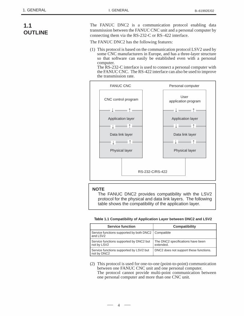
The FANUC DNC2 is a communication protocol enabling datatransmission between the FANUC CNC unit and a personal computer byconnecting them via the RS-232-C or RS–422 interface.
The FANUC DNC2 has the following features:
(1) This protocol is based on the communication protocol LSV2 used bysome CNC manufacturers in Europe, and has a three-layer structureso that software can easily be established even with a personalcomputer.The RS-232-C interface is used to connect a personal computer withthe FANUC CNC. The RS-422 interface can also be used to improvethe transmission rate.
CNC control program
Application layer
FANUC CNC
Data link layer
Physical layer
User application program
Application layer
Personal computer
Data link layer
Physical layer
RS-232-C/RS-422
�
�
��
�
� �
�
� �
�
�
NOTEThe FANUC DNC2 provides compatibility with the LSV2protocol for the physical and data link layers. The followingtable shows the compatibility of the application layer.
����� 1.1 Compatibility of Application Layer between DNC2 and LSV2
Service function Compatibility
Service functions supported by both DNC2and LSV2
Compatible
Service functions supported by DNC2 butnot by LSV2
The DNC2 specifications have beenextended.
Service functions supported by LSV2 butnot by DNC2
DNC2 does not support these functions.
(2) This protocol is used for one-to-one (point-to-point) communicationbetween one FANUC CNC unit and one personal computer.The protocol cannot provide multi-point communication betweenone personal computer and more than one CNC unit.
1.1OUTLINE
B–61992E/02 1. GENERALI. GENERAL
5
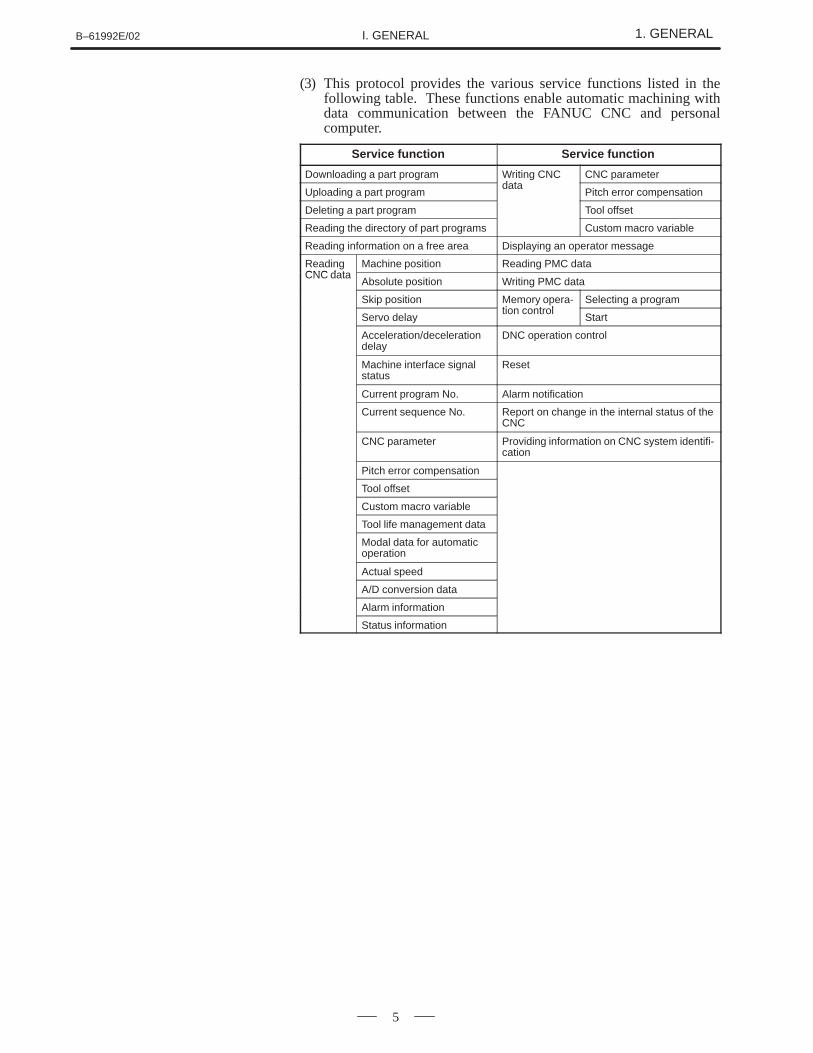
(3) This protocol provides the various service functions listed in thefollowing table. These functions enable automatic machining withdata communication between the FANUC CNC and personalcomputer.
Service function Service function
Downloading a part program Writing CNCd t
CNC parameter
Uploading a part programdata
Pitch error compensation
Deleting a part program Tool offset
Reading the directory of part programs Custom macro variable
Reading information on a free area Displaying an operator message
ReadingCNC d t
Machine position Reading PMC dataCNC data
Absolute position Writing PMC data
Skip position Memory opera-ti t l
Selecting a program
Servo delaytion control
Start
Acceleration/decelerationdelay
DNC operation control
Machine interface signalstatus
Reset
Current program No. Alarm notification
Current sequence No. Report on change in the internal status of theCNC
CNC parameter Providing information on CNC system identifi-cation
Pitch error compensation
Tool offset
Custom macro variable
Tool life management data
Modal data for automaticoperation
Actual speed
A/D conversion data
Alarm information
Status information
1. GENERAL B–61992E/02I. GENERAL
6
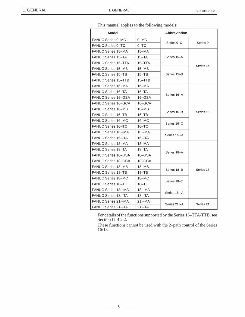
This manual applies to the following models:
Model Abbreviation
FANUC Series 0–MC 0–MCSeries 0 C Series 0
FANUC Series 0–TC 0–TCSeries 0–C Series 0
FANUC Series 15–MA 15–MA
FANUC Series 15–TA 15–TA Series 15–A
FANUC Series 15–TTA 15–TTASeries 15
FANUC Series 15–MB 15–MBSeries 15
FANUC Series 15–TB 15–TB Series 15–B
FANUC Series 15–TTB 15–TTB
FANUC Series 16–MA 16–MA
FANUC Series 16–TA 16–TASeries 16 A
FANUC Series 16–GSA 16–GSASeries 16–A
FANUC Series 16–GCA 16–GCA
FANUC Series 16–MB 16–MBSeries 16 B Series 16
FANUC Series 16–TB 16–TBSeries 16–B Series 16
FANUC Series 16–MC 16–MCSeries 16 C
FANUC Series 16–TC 16–TCSeries 16–C
FANUC Series 16i–MA 16i–MASeries 16i A
FANUC Series 16i–TA 16i–TASeries 16 –A
FANUC Series 18–MA 18–MA
FANUC Series 18–TA 18–TASeries 18 A
FANUC Series 18–GSA 18–GSASeries 18–A
FANUC Series 18–GCA 18–GCA
FANUC Series 18–MB 18–MBSeries 18 B Series 18
FANUC Series 18–TB 18–TBSeries 18–B Series 18
FANUC Series 18–MC 18–MCSeries 18 C
FANUC Series 18–TC 18–TCSeries 18–C
FANUC Series 18i–MA 18i–MASeries 18i A
FANUC Series 18i–TA 18i–TASeries 18 –A
FANUC Series 21i–MA 21i–MASeries 21i A Series 21
FANUC Series 21i–TA 21i–TASeries 21 –A Series 21
For details of the functions supported by the Series 15–TTA/TTB, seeSection II–4.2.2.These functions cannot be used with the 2–path control of the Series16/18.
B–61992E/02 2. CONFIGURATIONI. GENERAL
7
2 CONFIGURATION
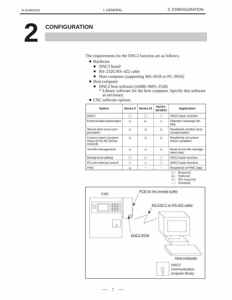
The requirements for the DNC2 function are as follows:� Hardware
� DNC2 board � RS–232C/RS–422 cable � Host computer (supporting MS–DOS or PC–DOS)
� Host computer � DNC2 host software (A08B–9001–J530)
* Library software for the host computer. Specify this softwareas necessary.
� CNC software options
Option Series 0 Series 15Series
16/18/21 Application
DNC2 � � � DNC2 basic function
External data input/output � � � Operator message dis-play
Stored pitch error com-pensation
� � � Read/write of pitch errorcompensation
Custom macro (custommacro B for the Series0/16/18)
� � � Read/write of custommacro variables
Tool life management � � � Read of tool life manage-ment data
Background editing � � � DNC2 basic function
I/O unit external control � � � DNC2 basic function
PMC � – – Read/write of PMC data
�: Required� : Optional�: Not required – : Standard
PCB for the remote buffer
RS-232-C or RS-422 cable
DNC2 ROM
Host computer
DNC2communicationprogram library
CNC

II. PROTOCOL
B–61992E/02 1. LAYERSII. PROTOCOL
11
1 LAYERS
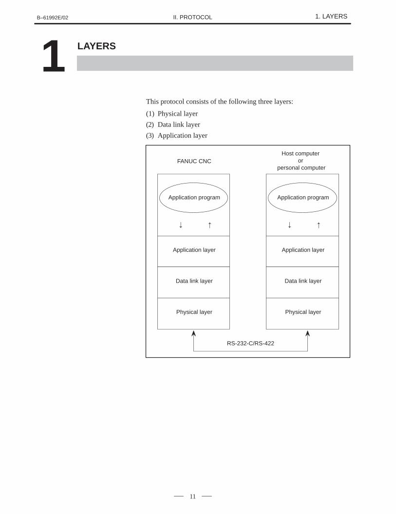
This protocol consists of the following three layers:
(1) Physical layer
(2) Data link layer
(3) Application layer
Application program
Application layer
Data link layer
Physical layer
� �
FANUC CNCHost computer
or personal computer
RS-232-C/RS-422
Application program
Application layer
Data link layer
Physical layer
� �

2. PHYSICAL LAYER B–61992E/02II. PROTOCOL
12
2 PHYSICAL LAYER
B–61992E/02 2. PHYSICAL LAYERII. PROTOCOL
13
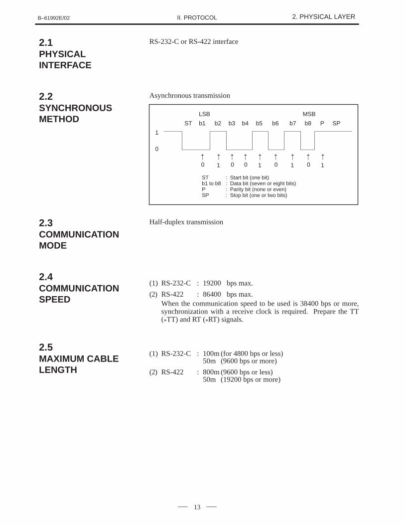
RS-232-C or RS-422 interface
Asynchronous transmission
ST b1 b2 b3 b4 b5 b6 b7 b8 P SP
LSB MSB
1
0
0�
1
�
0�
0�
0�
0�
1
�
1
�
1
�
ST : Start bit (one bit)b1 to b8 : Data bit (seven or eight bits)P : Parity bit (none or even)SP : Stop bit (one or two bits)
Half-duplex transmission
(1) RS-232-C : 19200 bps max.
(2) RS-422 : 86400 bps max.When the communication speed to be used is 38400 bps or more,synchronization with a receive clock is required. Prepare the TT(*TT) and RT (*RT) signals.
(1) RS-232-C : 100m (for 4800 bps or less)50m (9600 bps or more)
(2) RS-422 : 800m (9600 bps or less)50m (19200 bps or more)
2.1PHYSICALINTERFACE
2.2SYNCHRONOUSMETHOD
2.3COMMUNICATIONMODE
2.4COMMUNICATIONSPEED
2.5MAXIMUM CABLELENGTH
2. PHYSICAL LAYER B–61992E/02II. PROTOCOL
14
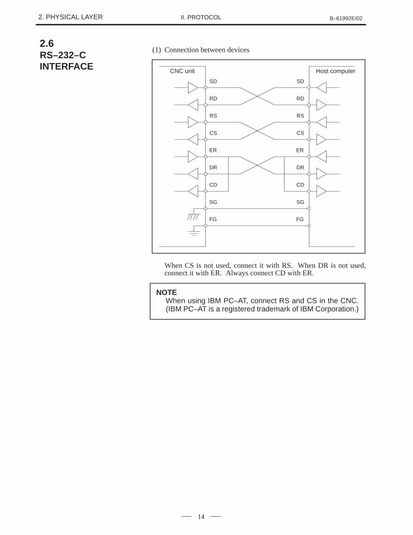
(1) Connection between devices
CS
RS
CNC unit
RD
SD
SG
CD
DR
ER
FG
CS
RS
RD
SD
SG
CD
DR
ER
FG
Host computer
When CS is not used, connect it with RS. When DR is not used,connect it with ER. Always connect CD with ER.
NOTEWhen using IBM PC–AT, connect RS and CS in the CNC.(IBM PC–AT is a registered trademark of IBM Corporation.)
2.6RS–232–CINTERFACE
B–61992E/02 2. PHYSICAL LAYERII. PROTOCOL
15
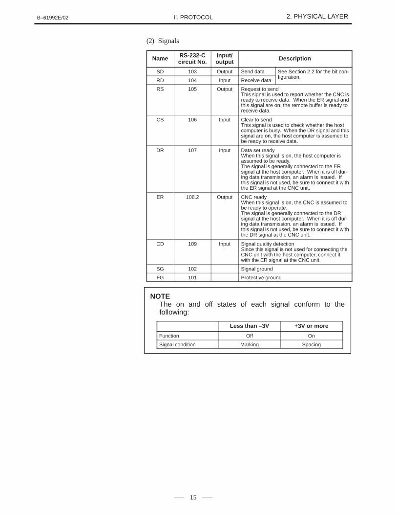
(2) Signals
Name RS-232-Ccircuit No.
Input/output Description
SD 103 Output Send data See Section 2.2 for the bit con-fi ti
RD 104 Input Receive datafiguration.
RS 105 Output Request to sendThis signal is used to report whether the CNC isready to receive data. When the ER signal andthis signal are on, the remote buffer is ready toreceive data.
CS 106 Input Clear to sendThis signal is used to check whether the hostcomputer is busy. When the DR signal and thissignal are on, the host computer is assumed tobe ready to receive data.
DR 107 Input Data set readyWhen this signal is on, the host computer isassumed to be ready.The signal is generally connected to the ERsignal at the host computer. When it is off dur-ing data transmission, an alarm is issued. Ifthis signal is not used, be sure to connect it withthe ER signal at the CNC unit.
ER 108.2 Output CNC readyWhen this signal is on, the CNC is assumed tobe ready to operate.The signal is generally connected to the DRsignal at the host computer. When it is off dur-ing data transmission, an alarm is issued. Ifthis signal is not used, be sure to connect it withthe DR signal at the CNC unit.
CD 109 Input Signal quality detectionSince this signal is not used for connecting theCNC unit with the host computer, connect itwith the ER signal at the CNC unit.
SG 102 Signal ground
FG 101 Protective ground
Less than –3V +3V or more
Function Off On
Signal condition Marking Spacing
NOTEThe on and off states of each signal conform to thefollowing:
2. PHYSICAL LAYER B–61992E/02II. PROTOCOL
16
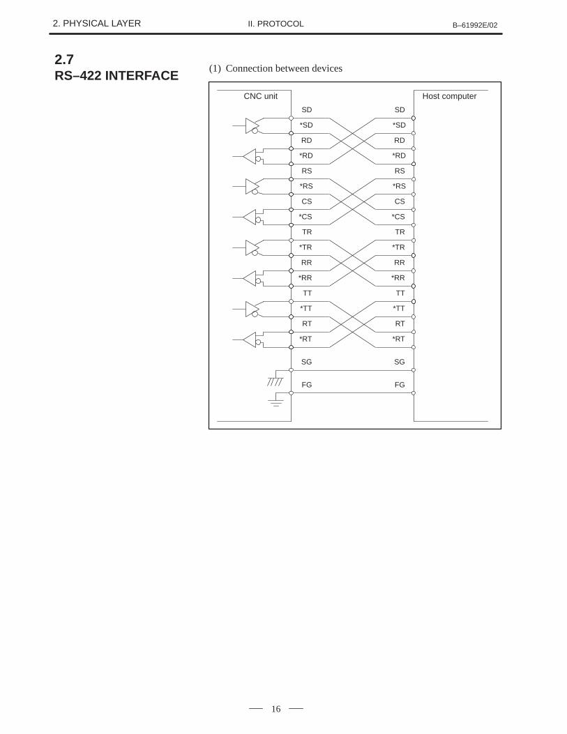
(1) Connection between devices
CNC unit
SG
FG
Host computer
SD
*SD
RD
*RD
RS
*RS
CS
*CS
TR
*TR
RR
*RR
TT
*TT
RT
*RT
SG
FG
SD
*SD
RD
*RD
RS
*RS
CS
*CS
TR
*TR
RR
*RR
TT
*TT
RT
*RT
2.7RS–422 INTERFACE
B–61992E/02 2. PHYSICAL LAYERII. PROTOCOL
17
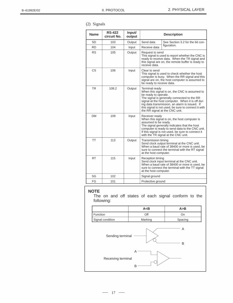
(2) Signals
Name RS-422 circuit No.
Input/output Description
SD 103 Output Send data See Section 3.2 for the bit con-fi ti
RD 104 Input Receive datafiguration.
RS 105 Output Request to sendThis signal is used to report whether the CNC isready to receive data. When the TR signal andthis signal are on, the remote buffer is ready toreceive data.
CS 106 Input Clear to sendThis signal is used to check whether the hostcomputer is busy. When the RR signal and thissignal are on, the host computer is assumed tobe ready to receive data.
TR 108.2 Output Terminal readyWhen this signal is on, the CNC is assumed tobe ready to operate.The signal is generally connected to the RRsignal at the host computer. When it is off dur-ing data transmission, an alarm is issued. Ifthis signal is not used, be sure to connect it withthe RR signal at the CNC unit.
DM 109 Input Receiver readyWhen this signal is on, the host computer isassumed to be ready.The signal generally indicates that the hostcomputer is ready to send data to the CNC unit.If this signal is not used, be sure to connect itwith the TR signal at the CNC unit.
TT 113 Output Transmission timingSend clock output terminal at the CNC unit.When a baud rate of 38400 or more is used, besure to connect the terminal with the RT signalat the host computer.
RT 115 Input Reception timingSend clock input terminal at the CNC unit.When a baud rate of 38400 or more is used, besure to connect the terminal with the TT signalat the host computer.
SG 102 Signal ground
FG 101 Protective ground
A<B A>B
Function Off On
Signal condition Marking Spacing
A
B
A
B
Sending terminal
Receiving terminal
NOTEThe on and off states of each signal conform to thefollowing:

3. DATA LINK LAYER B–61992E/02II. PROTOCOL
18
3 DATA LINK LAYER
The CNC unit and the host computer can operate on equal terms with eachother under this protocol. If a contention occurs, however, the CNC isgiven priority over the host computer in data transmission.
B–61992E/02 3. DATA LINK LAYERII. PROTOCOL
19
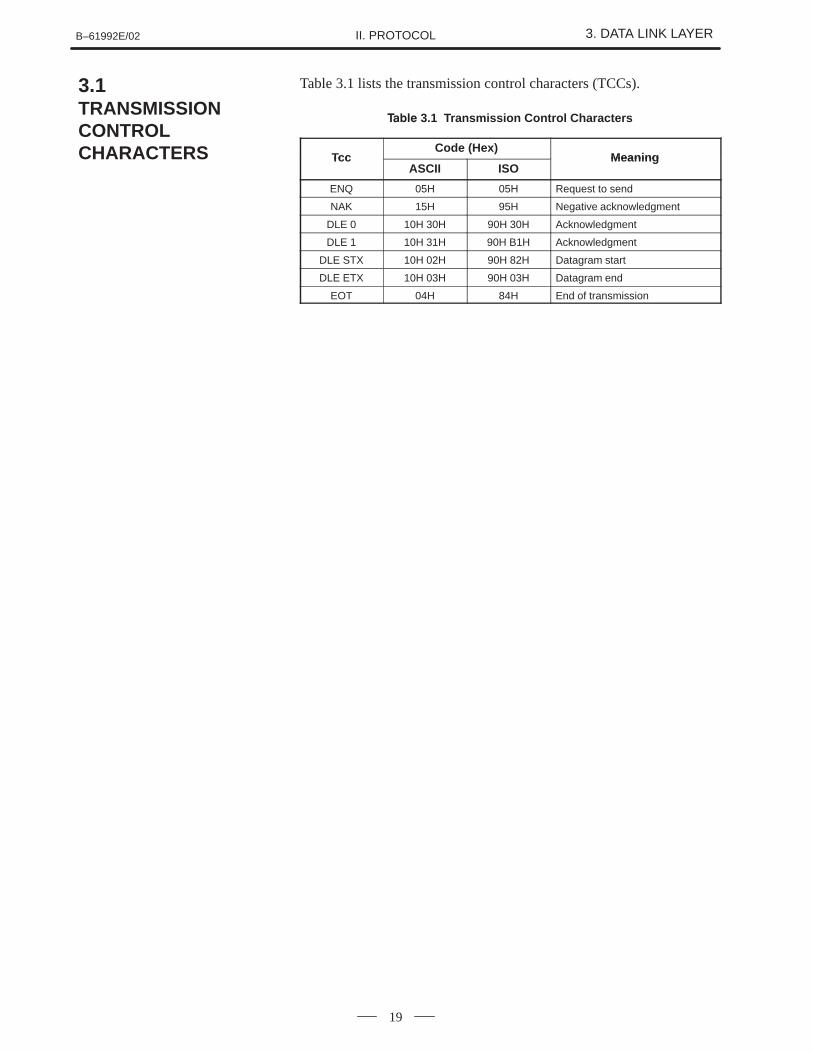
Table 3.1 lists the transmission control characters (TCCs).
����� 3.1 Transmission Control Characters
TccCode (Hex)
MeaningTccASCII ISO
Meaning
ENQ 05H 05H Request to send
NAK 15H 95H Negative acknowledgment
DLE 0 10H 30H 90H 30H Acknowledgment
DLE 1 10H 31H 90H B1H Acknowledgment
DLE STX 10H 02H 90H 82H Datagram start
DLE ETX 10H 03H 90H 03H Datagram end
EOT 04H 84H End of transmission
3.1TRANSMISSIONCONTROLCHARACTERS
3. DATA LINK LAYER B–61992E/02II. PROTOCOL
20
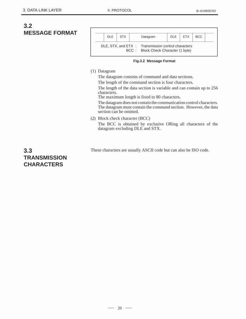
DLE STX Datagram DLE ETX BCC
DLE, STX, and ETX : Transmission control charactersDLE, STX, and BCC : Block Check Character (1 byte)
Fig.3.2 Message Format
(1) DatagramThe datagram consists of command and data sections.The length of the command section is four characters.The length of the data section is variable and can contain up to 256characters. The maximum length is fixed to 80 characters.The datagram does not contain the communication control characters.The datagram must contain the command section. However, the datasection can be omitted.
(2) Block check character (BCC)The BCC is obtained by exclusive ORing all characters of thedatagram excluding DLE and STX.
These characters are usually ASCII code but can also be ISO code.
3.2MESSAGE FORMAT
3.3TRANSMISSIONCHARACTERS
B–61992E/02 3. DATA LINK LAYERII. PROTOCOL
21
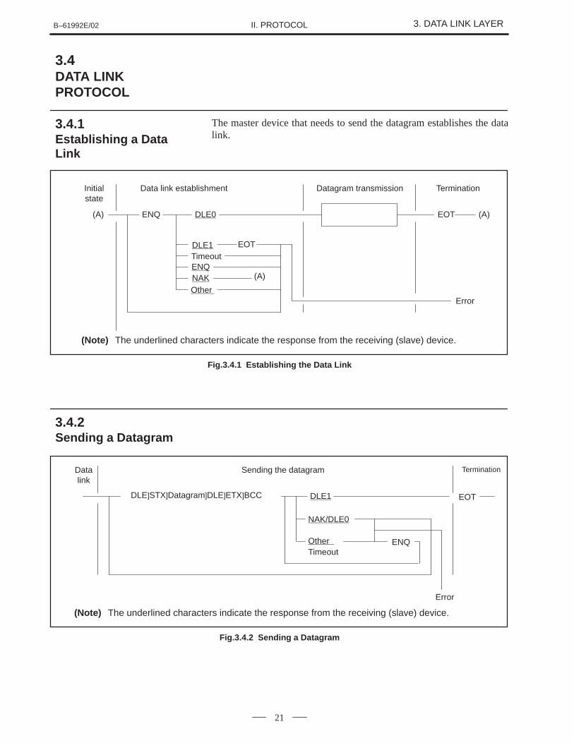
The master device that needs to send the datagram establishes the datalink.
ENQ DLE0
DLE1 EOTTimeoutENQNAKOther
(A)
Initialstate
(A) EOT
Error
Datagram transmission TerminationData link establishment
(A)
(Note) The underlined characters indicate the response from the receiving (slave) device.
Fig.3.4.1 Establishing the Data Link
EOT
Datalink
Sending the datagram
NAK/DLE0
Other Timeout
DLE]STX]Datagram]DLE]ETX]BCC DLE1
Termination
Error
(Note) The underlined characters indicate the response from the receiving (slave) device.
ENQ
Fig.3.4.2 Sending a Datagram
3.4DATA LINKPROTOCOL
3.4.1Establishing a DataLink
3.4.2Sending a Datagram
3. DATA LINK LAYER B–61992E/02II. PROTOCOL
22
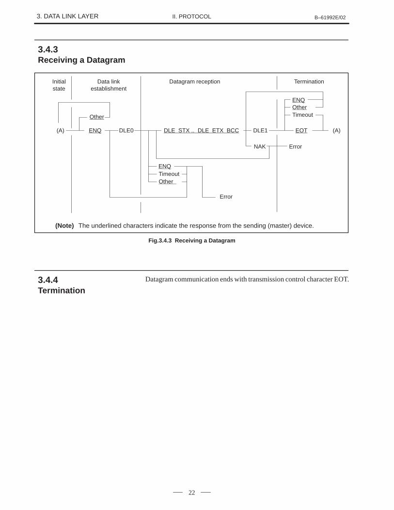
Initialstate
(A)
Error
Data linkestablishment
(Note) The underlined characters indicate the response from the sending (master) device.
Other
ENQ DLE0 DLE STX .. DLE ETX BCC DLE1 EOT
NAK
ENQTimeoutOther
Error
(A)
ENQOtherTimeout
TerminationDatagram reception
Fig.3.4.3 Receiving a Datagram
Datagram communication ends with transmission control character EOT.
3.4.3Receiving a Datagram
3.4.4Termination

B–61992E/02 4. APPLICATION LAYERII. PROTOCOL
23
4 APPLICATION LAYER
This chapter outlines the application layer. For more details, see thedescription given later.
4. APPLICATION LAYER B–61992E/02II. PROTOCOL
24
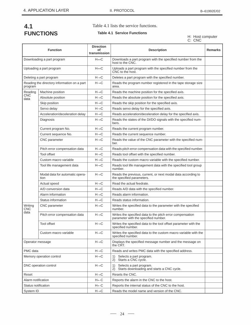
Table 4.1 lists the service functions.
Table 4.1 Service FunctionsH: Host computerC: CNC
FunctionDirection
of transmission
Description Remarks
Downloading a part program H�C Downloads a part program with the specified number from thehost to the CNC.
Uploading a part program H�C Uploads a part program with the specified number from theCNC to the host.
Deleting a part program H�C Deletes a part program with the specified number.
Reading the directory information on a partprogram
H�C Reads the program number registered in the tape storage sizearea.
ReadingCNC
Machine position H�C Reads the machine position for the specified axis.CNCdata Absolute position H�C Reads the absolute position for the specified axis.data
Skip position H�C Reads the skip position for the specified axis.
Servo delay H�C Reads servo delay for the specified axis.
Acceleration/deceleration delay H�C Reads acceleration/deceleration delay for the specified axis.
Diagnosis H�C Reads the states of the DI/DO signals with the specified num-bers.
Current program No. H�C Reads the current program number.
Current sequence No. H�C Reads the current sequence number.
CNC parameter H�C Reads the value of the CNC parameter with the specified num-ber.
Pitch error compensation data H�C Reads pitch error compensation data with the specified number.
Tool offset H�C Reads tool offset with the specified number.
Custom macro variable H�C Reads the custom macro variable with the specified number.
Tool life management data H�C Reads tool life management data with the specified tool groupnumber.
Modal data for automatic opera-tion
H�C Reads the previous, current, or next modal data according tothe specified parameters.
Actual speed H�C Read the actual feedrate.
A/D conversion data H�C Reads A/D data with the specified number.
Alarm information H�C Reads alarm information.
Status information H�C Reads status information.
WritingCNCdata
CNC parameter H�C Writes the specified data to the parameter with the specifiednumber.
dataPitch error compensation data H�C Writes the specified data to the pitch error compensation
parameter with the specified number.
Tool offset H�C Writes the specified data to the tool offset parameter with thespecified number.
Custom macro variable H�C Writes the specified data to the custom macro variable with thespecified number.
Operator message H�C Displays the specified message number and the message onthe CRT.
PMC data H�C Reads and writes PMC data with the specified address.
Memory operation control H�C 1) Selects a part program.2) Starts a CNC cycle.
DNC operation control H�C 1) Selects a part program.2) Starts downloading and starts a CNC cycle.
Reset H�C Resets the CNC.
Alarm notification H�C Reports the alarm in the CNC to the host.
Status notification H�C Reports the internal status of the CNC to the host.
System ID H�C Reads the model name and version of the CNC.
4.1FUNCTIONS
B–61992E/02 4. APPLICATION LAYERII. PROTOCOL
25
The datagram consists of the command section and the omissible datasection. The command section contains four characters. The data sectioncontains variable-length data. The maximum length of the data sectionis specified by the CNC parameter. Subsections 4.2.1 and 4.2.2 list andexplain the datagram commands. Subsection 4.2.4 describes the datasection.
4.2DATAGRAM SYNTAX
4. APPLICATION LAYER B–61992E/02II. PROTOCOL
26
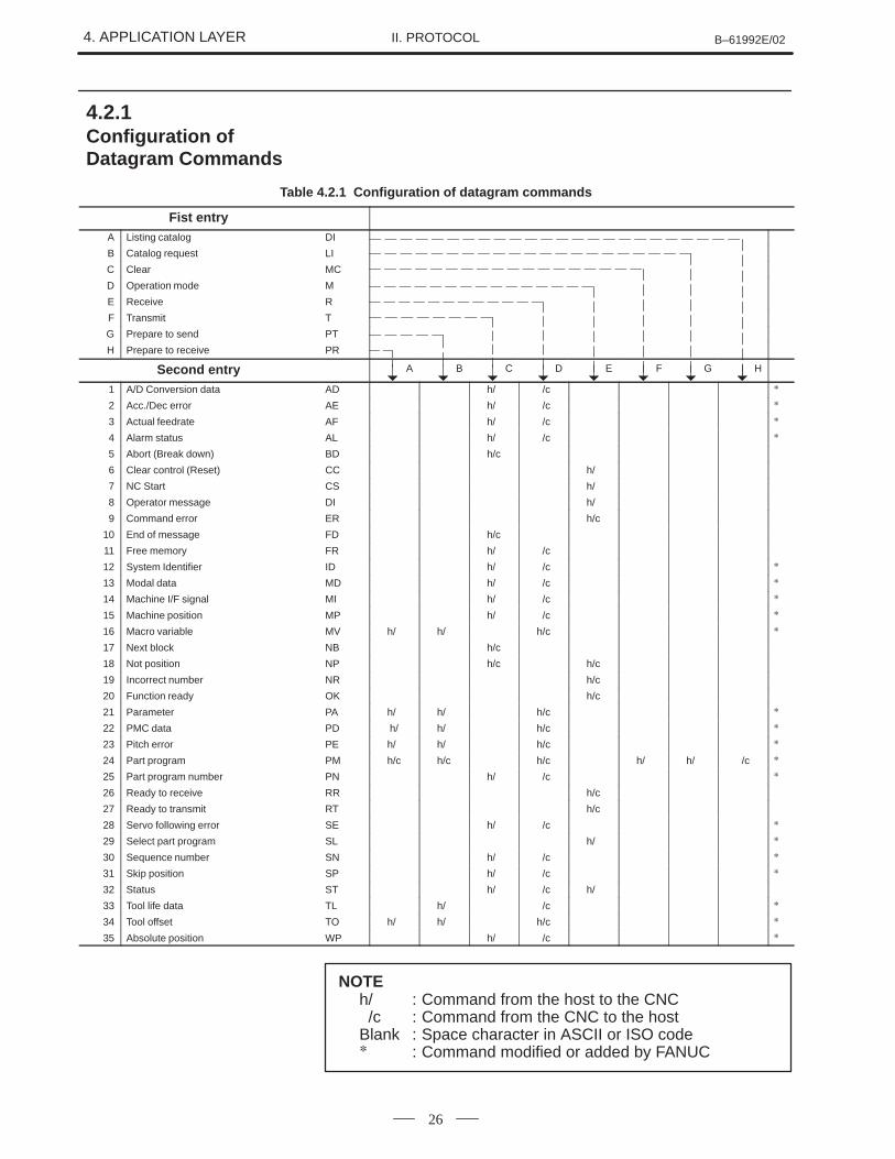
Table 4.2.1 Configuration of datagram commands
Fist entryA Listing catalog DI
B Catalog request LI
C Clear MC
D Operation mode M
E Receive R
F Transmit T
G Prepare to send PT
H Prepare to receive PR
Second entry A B C D E F G H
1 A/D Conversion data AD h/c h/c �
2 Acc./Dec error AE h/c h/c �
3 Actual feedrate AF h/c h/c �
4 Alarm status AL h/c h/c �
5 Abort (Break down) BD h/c
6 Clear control (Reset) CC h/c
7 NC Start CS h/c
8 Operator message DI h/c
9 Command error ER h/c
10 End of message FD h/c
11 Free memory FR h/c h/c
12 System Identifier ID h/c h/c �
13 Modal data MD h/c h/c �
14 Machine I/F signal MI h/c h/c �
15 Machine position MP h/c h/c �
16 Macro variable MV h/c h/c h/c �
17 Next block NB h/c
18 Not position NP h/c h/c
19 Incorrect number NR h/c
20 Function ready OK h/c
21 Parameter PA h/c h/c h/c �
22 PMC data PD h/ h/c h/c �
23 Pitch error PE h/c h/c h/c �
24 Part program PM h/c h/c h/c h/c h/c h/c �
25 Part program number PN h/c h/c �
26 Ready to receive RR h/c
27 Ready to transmit RT h/c
28 Servo following error SE h/c h/c �
29 Select part program SL h/c �
30 Sequence number SN h/c h/c �
31 Skip position SP h/c h/c �
32 Status ST h/c h/c h/c
33 Tool life data TL h/c h/c �
34 Tool offset TO h/c h/c h/c �
35 Absolute position WP h/c h/c �
NOTEh/ : Command from the host to the CNC /c : Command from the CNC to the hostBlank : Space character in ASCII or ISO code� : Command modified or added by FANUC
4.2.1Configuration ofDatagram Commands
B–61992E/02 4. APPLICATION LAYERII. PROTOCOL
27
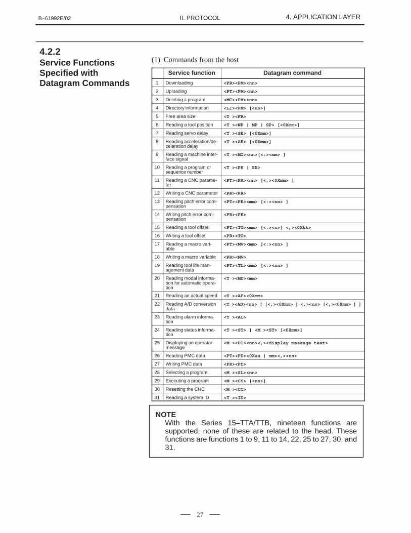
(1) Commands from the host
Service function Datagram command
1 Downloading <PR><PM><nn>
2 Uploading <PT><PM><nn>
3 Deleting a program <MC><PM><nn>
4 Directory information <LI><PM> [<nn>]
5 Free area size <T ><FR>
6 Reading a tool position <T ><WP | MP | SP> [<0Xmm>]
7 Reading servo delay <T ><SE> [<0Xmm>]
8 Reading acceleration/de-celeration delay
<T ><AE> [<0Xmm>]
9 Reading a machine inter-face signal
<T ><MI><nn>[<:><mm> ]
10 Reading a program orsequence number
<T ><PN | SN>
11 Reading a CNC parame-ter
<PT><PA><nn> [<,><0Xmm> ]
12 Writing a CNC parameter <PR><PA>
13 Reading pitch error com-pensation
<PT><PE><mm> [<:><nn> ]
14 Writing pitch error com-pensation
<PR><PE>
15 Reading a tool offset <PT><TO><mm> [<:><n>] <,><0Xkk>
16 Writing a tool offset <PR><TO>
17 Reading a macro vari-able
<PT><MV><mm> [<:><nn> ]
18 Writing a macro variable <PR><MV>
19 Reading tool life man-agement data
<PT><TL><mm> [<:><nn> ]
20 Reading modal informa-tion for automatic opera-tion
<T ><MD><mm>
21 Reading an actual speed <T ><AF><0Xmm>
22 Reading A/D conversiondata
<T ><AD><nn> [ [<,><0Xmm> ] <,><nn> [<,><0Xmm> ] ]
23 Reading alarm informa-tion
<T ><AL>
24 Reading status informa-tion
<T ><ST> | <M ><ST> [<0Xmm>]
25 Displaying an operatormessage
<M ><DI><nn><,><display message text>
26 Reading PMC data <PT><PD><0Xaa | mm><,><nn>
27 Writing PMC data <PR><PD>
28 Selecting a program <M ><SL><nn>
29 Executing a program <M ><CS> [<nn>]
30 Resetting the CNC <M ><CC>
31 Reading a system ID <T ><ID>
NOTEWith the Series 15–TTA/TTB, nineteen functions aresupported; none of these are related to the head. Thesefunctions are functions 1 to 9, 11 to 14, 22, 25 to 27, 30, and31.
4.2.2Service FunctionsSpecified withDatagram Commands
4. APPLICATION LAYER B–61992E/02II. PROTOCOL
28
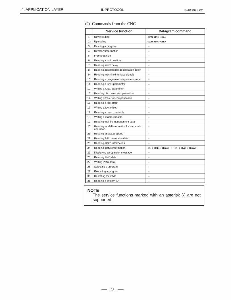
(2) Commands from the CNC
Service function Datagram command
1 Downloading <PT><PM><nn>
2 Uploading <PR><PM><nn>
3 Deleting a program �
4 Directory information �
5 Free area size �
6 Reading a tool position �
7 Reading servo delay �
8 Reading acceleration/deceleration delay �
9 Reading machine interface signals �
10 Reading a program or sequence number �
11 Reading a CNC parameter �
12 Writing a CNC parameter �
13 Reading pitch error compensation �
14 Writing pitch error compensation �
15 Reading a tool offset �
16 Writing a tool offset �
17 Reading a macro variable �
18 Writing a macro variable �
19 Reading tool life management data �
20 Reading modal information for automaticoperation
�
21 Reading an actual speed �
22 Reading A/D conversion data �
23 Reading alarm information �
24 Reading status information <R ><ST><0Xss> | <R ><AL><0Xaa>
25 Displaying an operator message �
26 Reading PMC data �
27 Writing PMC data �
28 Selecting a program �
29 Executing a program �
30 Resetting the CNC �
31 Reading a system ID �
NOTEThe service functions marked with an asterisk (*) are notsupported.
B–61992E/02 4. APPLICATION LAYERII. PROTOCOL
29
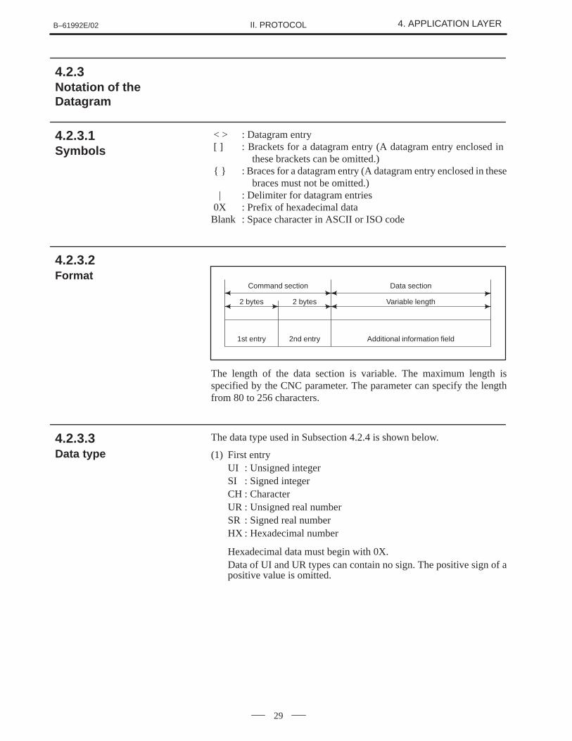
< > : Datagram entry [ ] : Brackets for a datagram entry (A datagram entry enclosed in
these brackets can be omitted.) { } : Braces for a datagram entry (A datagram entry enclosed in these
braces must not be omitted.) | : Delimiter for datagram entries 0X : Prefix of hexadecimal dataBlank : Space character in ASCII or ISO code
Command section Data section
2 bytes 2 bytes Variable length
1st entry 2nd entry Additional information field
The length of the data section is variable. The maximum length isspecified by the CNC parameter. The parameter can specify the lengthfrom 80 to 256 characters.
The data type used in Subsection 4.2.4 is shown below.
(1) First entryUI : Unsigned integerSI : Signed integerCH : CharacterUR : Unsigned real numberSR : Signed real numberHX : Hexadecimal number
Hexadecimal data must begin with 0X.Data of UI and UR types can contain no sign. The positive sign of apositive value is omitted.
4.2.3Notation of theDatagram
4.2.3.1 Symbols
4.2.3.2 Format
4.2.3.3 Data type
4. APPLICATION LAYER B–61992E/02II. PROTOCOL
30
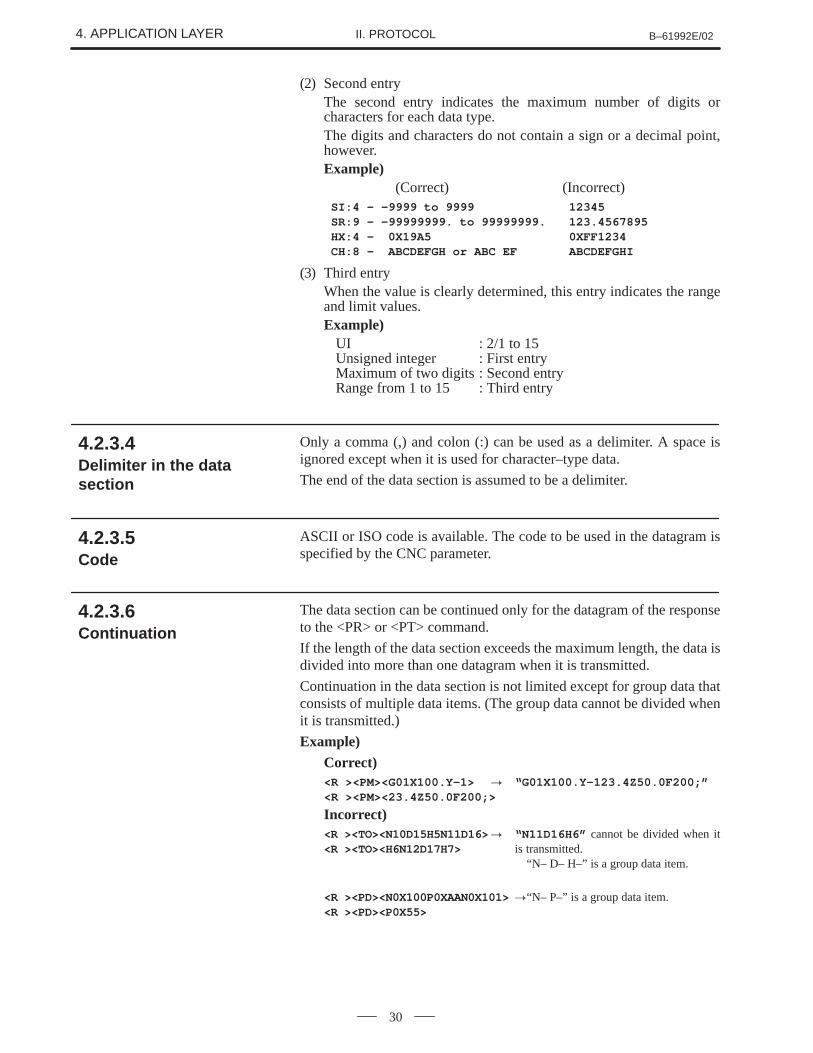
(2) Second entryThe second entry indicates the maximum number of digits orcharacters for each data type.The digits and characters do not contain a sign or a decimal point,however.Example)
(Correct) (Incorrect)SI:4 – –9999 to 9999 12345SR:9 – –99999999. to 99999999. 123.4567895HX:4 – 0X19A5 0XFF1234CH:8 – ABCDEFGH or ABC EF ABCDEFGHI
(3) Third entryWhen the value is clearly determined, this entry indicates the rangeand limit values.Example)
UI : 2/1 to 15Unsigned integer : First entryMaximum of two digits : Second entryRange from 1 to 15 : Third entry
Only a comma (,) and colon (:) can be used as a delimiter. A space isignored except when it is used for character–type data.
The end of the data section is assumed to be a delimiter.
ASCII or ISO code is available. The code to be used in the datagram isspecified by the CNC parameter.
The data section can be continued only for the datagram of the responseto the <PR> or <PT> command.
If the length of the data section exceeds the maximum length, the data isdivided into more than one datagram when it is transmitted.
Continuation in the data section is not limited except for group data thatconsists of multiple data items. (The group data cannot be divided whenit is transmitted.)
Example)Correct)<R ><PM><G01X100.Y–1> � “G01X100.Y–123.4Z50.0F200;”<R ><PM><23.4Z50.0F200;>
Incorrect)<R ><TO><N10D15H5N11D16>� “N11D16H6” cannot be divided when it<R ><TO><H6N12D17H7> is transmitted.
“N– D– H–” is a group data item.
<R ><PD><N0X100P0XAAN0X101>�“N– P–” is a group data item.<R ><PD><P0X55>
4.2.3.4 Delimiter in the datasection
4.2.3.5 Code
4.2.3.6 Continuation
B–61992E/02 4. APPLICATION LAYERII. PROTOCOL
31
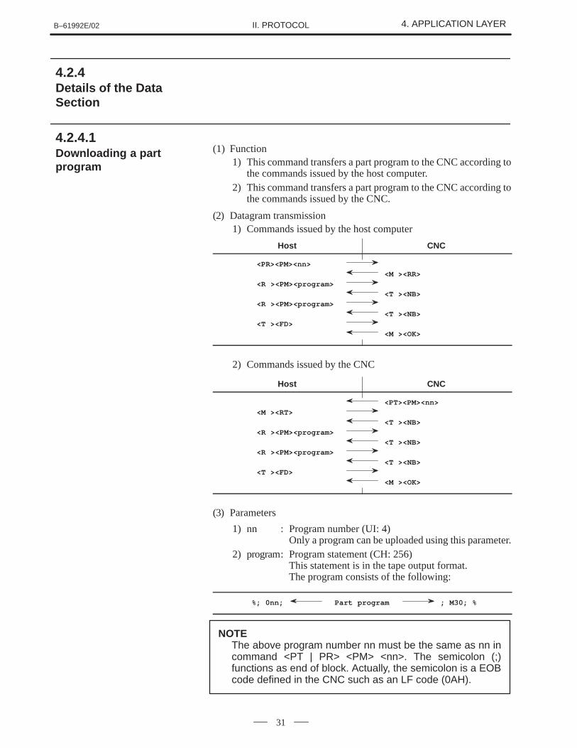
(1) Function1) This command transfers a part program to the CNC according to
the commands issued by the host computer.2) This command transfers a part program to the CNC according to
the commands issued by the CNC.
(2) Datagram transmission1) Commands issued by the host computer
Host CNC
<PR><PM><nn>
<M ><RR>
<R ><PM><program>
<T ><NB>
<R ><PM><program>
<T ><NB>
<T ><FD>
<M ><OK>
2) Commands issued by the CNC
Host CNC
<PT><PM><nn>
<M ><RT>
<T ><NB>
<R ><PM><program>
<T ><NB>
<R ><PM><program>
<T ><NB>
<T ><FD>
<M ><OK>
(3) Parameters
1) nn : Program number (UI: 4)Only a program can be uploaded using this parameter.
2) program: Program statement (CH: 256)This statement is in the tape output format.The program consists of the following:
%; 0nn; Part program ; M30; %
NOTEThe above program number nn must be the same as nn incommand <PT | PR> <PM> <nn>. The semicolon (;)functions as end of block. Actually, the semicolon is a EOBcode defined in the CNC such as an LF code (0AH).
4.2.4Details of the DataSection
4.2.4.1 Downloading a partprogram
4. APPLICATION LAYER B–61992E/02II. PROTOCOL
32
(4) Negative acknowledgment1) M_NR [0XF61F] :
The program with the same number has already been found.2) M_NP [0XF62D] :
The program is write–protected.3) M_NP [0XFDFB] :
An alarm is raised in the CNC. (For Series 0/16/18/21)4) T_BD [0XF61E] :
Insufficient free area in memory5) Note
Release background edit mode and simultaneous edit mode(Series 15 only) in advance.
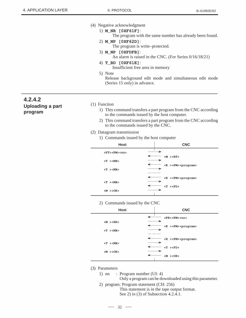
(1) Function1) This command transfers a part program from the CNC according
to the commands issued by the host computer.2) This command transfers a part program from the CNC according
to the commands issued by the CNC.
(2) Datagram transmission1) Commands issued by the host computer
Host CNC
<PT><PM><nn>
<M ><RT>
<T ><NB>
<R ><PM><program>
<T ><NB>
<R ><PM><program>
<T ><NB>
<T ><FD>
<M ><OK>
2) Commands issued by the CNC
Host CNC
<PR><PM><nn>
<M ><RR>
<R ><PM><program>
<T ><NB>
<R ><PM><program>
<T ><NB>
<T ><FD>
<M ><OK>
<M ><OK>
(3) Parameters1) nn : Program number (UI: 4)
Only a program can be downloaded using this parameter.2) program: Program statement (CH: 256)
This statement is in the tape output format.See 2) in (3) of Subsection 4.2.4.1.
4.2.4.2 Uploading a partprogram
B–61992E/02 4. APPLICATION LAYERII. PROTOCOL
33
(4) Negative acknowledgment1) M_NR [0XF625] : No program is found.2) M_NP [0XFDFB] : An alarm occurred in the CNC.
(For Series 0 only)
(5) NoteRelease background edit mode and simultaneous edit mode (Series15 only) in advance.
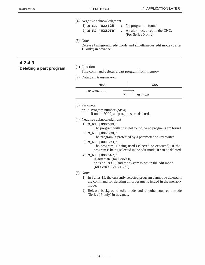
(1) FunctionThis command deletes a part program from memory.
(2) Datagram transmission
Host CNC
<MC><PM><nn>
<M ><OK>
(3) Parameternn : Program number (SI: 4)
If nn is –9999, all programs are deleted.
(4) Negative acknowledgment1) M_NR [0XFB9D] :
The program with nn is not found, or no programs are found.2) M_NP [0XFB98] :
The program is protected by a parameter or key switch.3) M_NP [0XFB93] :
The program is being used (selected or executed). If the program is being selected in the edit mode, it can be deleted.
4) M_NP [0XFBA7] : Alarm state (for Series 0)nn is no –9999, and the system is not in the edit mode. (for Series 15/16/18/21)
(5) Notes1) In Series 15, the currently selected program cannot be deleted if
the command for deleting all programs is issued in the memorymode.
2) Release background edit mode and simultaneous edit mode(Series 15 only) in advance.
4.2.4.3 Deleting a part program
4. APPLICATION LAYER B–61992E/02II. PROTOCOL
34
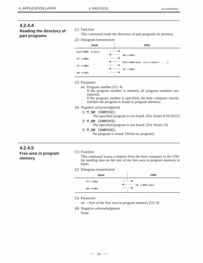
(1) FunctionThis command reads the directory of part programs in memory.
(2) Datagram transmission
Host CNC
<LI><PM> [<nn>]
<M ><RT>
<T ><NB>
<DI><PM><nn> [<<,><nn>>. . .]
<T ><NB>
<T ><FD>
<M ><OK>
(3) Parameternn: Program number (UI: 4)
If the program number is omitted, all program numbers are reported.If the program number is specified, the host computer checks whether the program is found in program memory.
(4) Negative acknowledgment1) T_NP [0XFC02] :
The specified program is not found. (For Series 0/16/18/21)2) T_NP [0XFC03] :
The specified program is not found. (For Series 15)3) T_NP [0XFC02] :
No program is found. (When no program)
(1) FunctionThis command issues a request from the host computer to the CNCfor sending data on the size of the free area in program memory inbytes.
(2) Datagram transmission
Host CNC
<T ><FR>
<R ><FR><nn>
<M ><OK>
(3) Parameternn : Size of the free area in program memory (UI: 9)
(4) Negative acknowledgmentNone
4.2.4.4 Reading the directory ofpart programs
4.2.4.5 Free area in programmemory
B–61992E/02 4. APPLICATION LAYERII. PROTOCOL
35
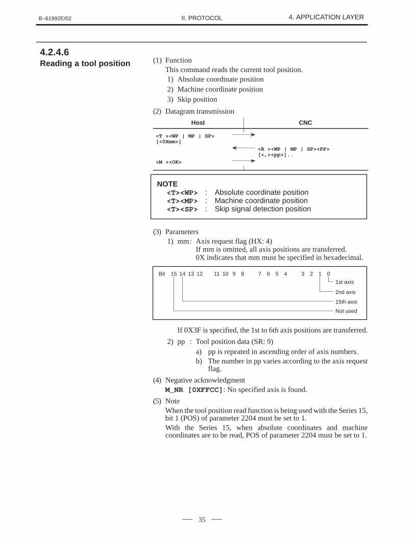
(1) FunctionThis command reads the current tool position.1) Absolute coordinate position2) Machine coordinate position3) Skip position
(2) Datagram transmission
Host CNC
<T ><WP | MP | SP>[<0Xmm>]
<R ><WP | MP | SP><PP>[<,><pp>]..
<M ><OK>
NOTE<T><WP> : Absolute coordinate position<T><MP> : Machine coordinate position<T><SP> : Skip signal detection position
(3) Parameters1) mm: Axis request flag (HX: 4)
If mm is omitted, all axis positions are transferred.0X indicates that mm must be specified in hexadecimal.
Bit 15 14 13 12 11 10 9 8 7 6 5 4 3 2 1 0
1st axis
2nd axis
15th axis
Not used
If 0X3F is specified, the 1st to 6th axis positions are transferred.
2) pp : Tool position data (SR: 9)a) pp is repeated in ascending order of axis numbers.b) The number in pp varies according to the axis request
flag.
(4) Negative acknowledgmentM_NR [0XFFCC] : No specified axis is found.
(5) NoteWhen the tool position read function is being used with the Series 15,bit 1 (POS) of parameter 2204 must be set to 1.With the Series 15, when absolute coordinates and machinecoordinates are to be read, POS of parameter 2204 must be set to 1.
4.2.4.6 Reading a tool position
4. APPLICATION LAYER B–61992E/02II. PROTOCOL
36
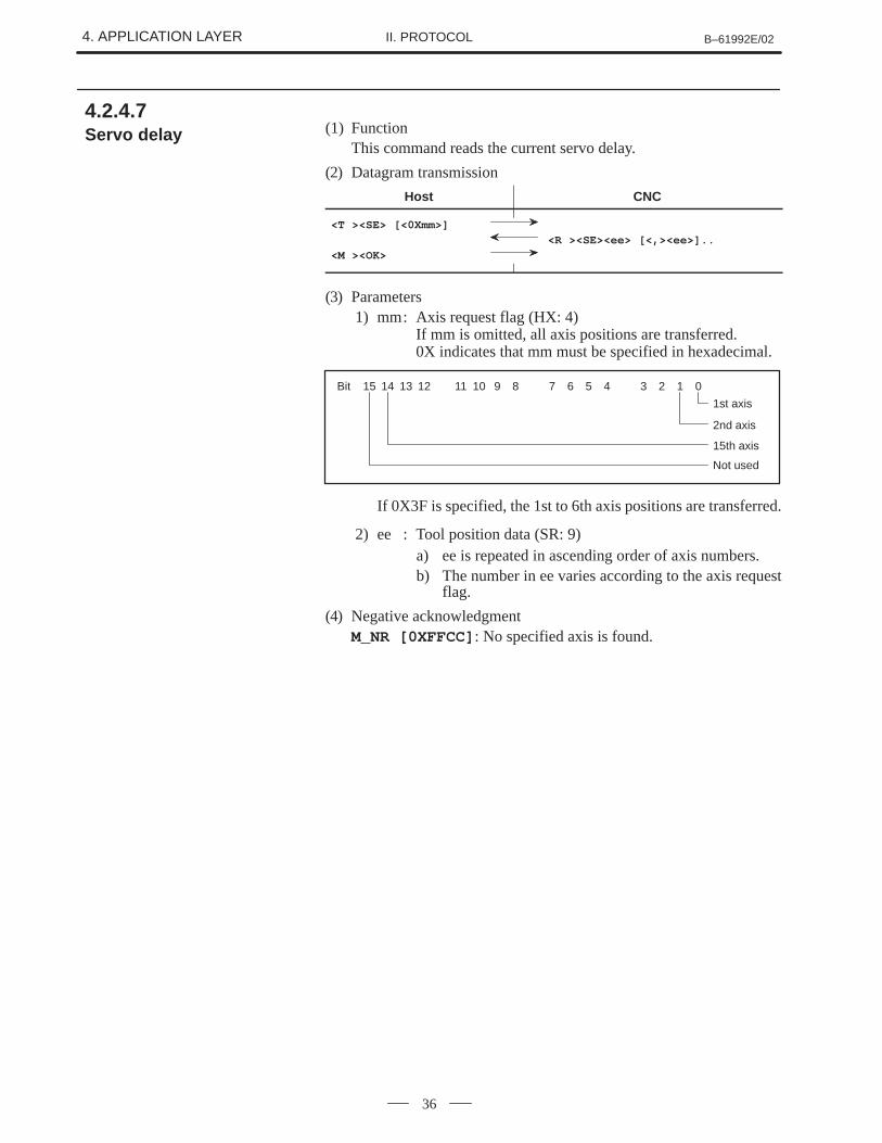
(1) FunctionThis command reads the current servo delay.
(2) Datagram transmission
Host CNC
<T ><SE> [<0Xmm>]
<R ><SE><ee> [<,><ee>]..
<M ><OK>
(3) Parameters1) mm: Axis request flag (HX: 4)
If mm is omitted, all axis positions are transferred.0X indicates that mm must be specified in hexadecimal.
Bit 15 14 13 12 11 10 9 8 7 6 5 4 3 2 1 0
1st axis
2nd axis
15th axis
Not used
If 0X3F is specified, the 1st to 6th axis positions are transferred.
2) ee : Tool position data (SR: 9)a) ee is repeated in ascending order of axis numbers.b) The number in ee varies according to the axis request
flag.
(4) Negative acknowledgmentM_NR [0XFFCC] : No specified axis is found.
4.2.4.7 Servo delay
B–61992E/02 4. APPLICATION LAYERII. PROTOCOL
37
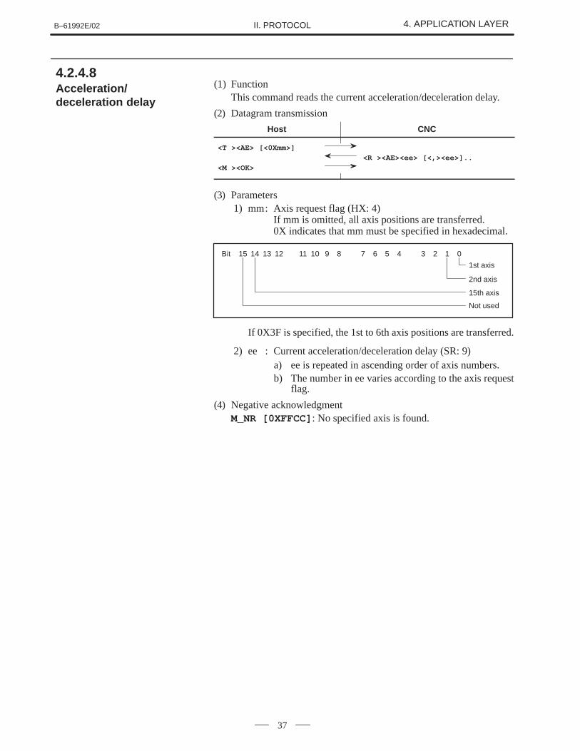
(1) FunctionThis command reads the current acceleration/deceleration delay.
(2) Datagram transmission
Host CNC
<T ><AE> [<0Xmm>]
<R ><AE><ee> [<,><ee>]..
<M ><OK>
(3) Parameters1) mm: Axis request flag (HX: 4)
If mm is omitted, all axis positions are transferred.0X indicates that mm must be specified in hexadecimal.
Bit 15 14 13 12 11 10 9 8 7 6 5 4 3 2 1 0
1st axis
2nd axis
15th axis
Not used
If 0X3F is specified, the 1st to 6th axis positions are transferred.
2) ee : Current acceleration/deceleration delay (SR: 9)a) ee is repeated in ascending order of axis numbers.b) The number in ee varies according to the axis request
flag.
(4) Negative acknowledgmentM_NR [0XFFCC] : No specified axis is found.
4.2.4.8 Acceleration/deceleration delay
4. APPLICATION LAYER B–61992E/02II. PROTOCOL
38
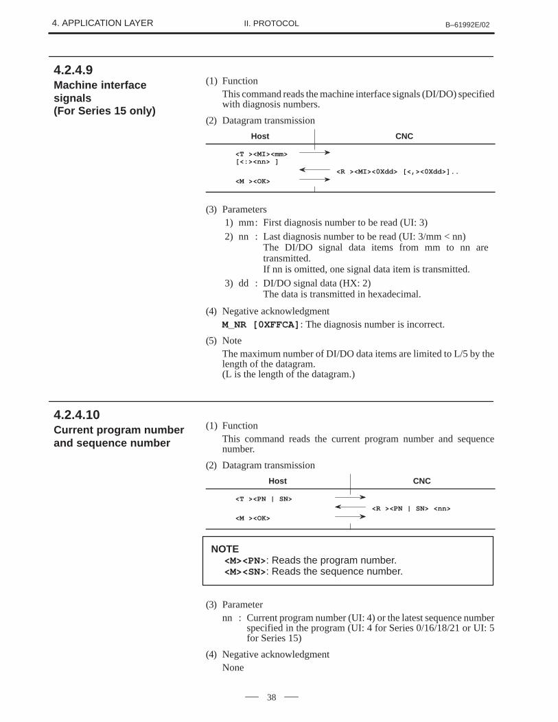
(1) FunctionThis command reads the machine interface signals (DI/DO) specifiedwith diagnosis numbers.
(2) Datagram transmission
Host CNC
<T ><MI><mm> [<:><nn> ]
<R ><MI><0Xdd> [<,><0Xdd>]..
<M ><OK>
(3) Parameters1) mm: First diagnosis number to be read (UI: 3)2) nn : Last diagnosis number to be read (UI: 3/mm < nn)
The DI/DO signal data items from mm to nn are transmitted.If nn is omitted, one signal data item is transmitted.
3) dd : DI/DO signal data (HX: 2)The data is transmitted in hexadecimal.
(4) Negative acknowledgmentM_NR [0XFFCA] : The diagnosis number is incorrect.
(5) NoteThe maximum number of DI/DO data items are limited to L/5 by thelength of the datagram.(L is the length of the datagram.)
(1) FunctionThis command reads the current program number and sequencenumber.
(2) Datagram transmission
Host CNC
<T ><PN | SN>
<R ><PN | SN> <nn>
<M ><OK>
NOTE<M><PN>: Reads the program number.<M><SN>: Reads the sequence number.
(3) Parameternn : Current program number (UI: 4) or the latest sequence number
specified in the program (UI: 4 for Series 0/16/18/21 or UI: 5for Series 15)
(4) Negative acknowledgmentNone
4.2.4.9 Machine interfacesignals (For Series 15 only)
4.2.4.10 Current program numberand sequence number
B–61992E/02 4. APPLICATION LAYERII. PROTOCOL
39
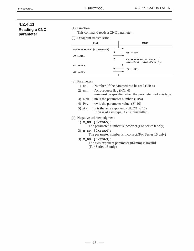
(1) FunctionThis command reads a CNC parameter.
(2) Datagram transmission
Host CNC
<PT><PA><nn> [<,><OXmm>]
<M ><RT>
<T ><NB>
<R ><PA><Nnn>< <Pvv> |<Ax><Pvv> [<Ax><Pvv> ]..
<T ><NB>
<T ><FD>
<M ><OK>
(3) Parameters1) nn : Number of the parameter to be read (UI: 4)2) mm : Axis request flag (HX: 4)
mm must be specified when the parameter is of axis type.3) Nnn : nn is the parameter number. (UI:4)4) Pvv : vv is the parameter value. (SI:10)5) Ax : x is the axis exponent. (UI: 2/1 to 15)
If nn is of axis type, Ax is transmitted.
(4) Negative acknowledgment1) M_NR [0XFBA5] :
The parameter number is incorrect.(For Series 0 only)2) M_NR [0XFBA4] :
The parameter number is incorrect.(For Series 15 only)3) M_NR [0XFBA3] :
The axis exponent parameter (0Xmm) is invalid. (For Series 15 only)
4.2.4.11 Reading a CNCparameter
4. APPLICATION LAYER B–61992E/02II. PROTOCOL
40
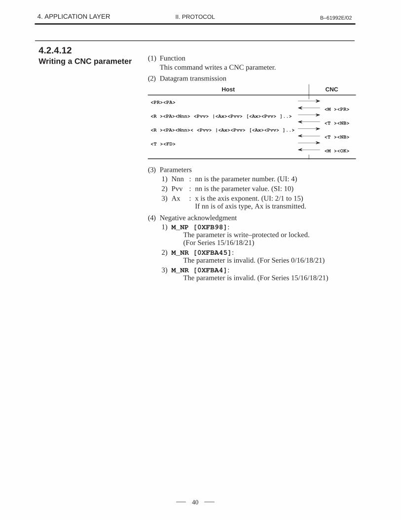
(1) FunctionThis command writes a CNC parameter.
(2) Datagram transmission
Host CNC
<PR><PA>
<M ><PR>
<R ><PA><Nnn> <Pvv> |<Ax><Pvv> [<Ax><Pvv> ]..>
<T ><NB>
<R ><PA><Nnn>< <Pvv> |<Ax><Pvv> [<Ax><Pvv> ]..>
<T ><NB>
<T ><FD>
<M ><OK>
(3) Parameters1) Nnn : nn is the parameter number. (UI: 4)2) Pvv : nn is the parameter value. (SI: 10)3) Ax : x is the axis exponent. (UI: 2/1 to 15)
If nn is of axis type, Ax is transmitted.
(4) Negative acknowledgment1) M_NP [0XFB98] :
The parameter is write–protected or locked. (For Series 15/16/18/21)
2) M_NR [0XFBA45] : The parameter is invalid. (For Series 0/16/18/21)
3) M_NR [0XFBA4] : The parameter is invalid. (For Series 15/16/18/21)
4.2.4.12 Writing a CNC parameter
B–61992E/02 4. APPLICATION LAYERII. PROTOCOL
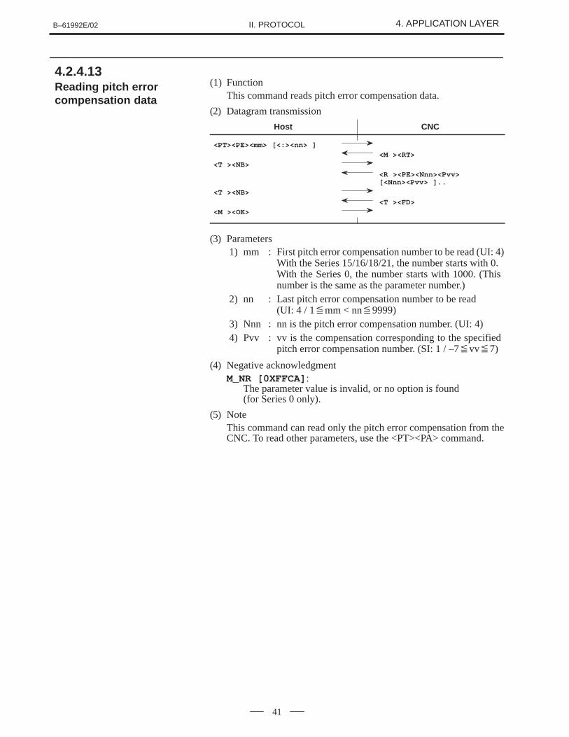
41
(1) FunctionThis command reads pitch error compensation data.
(2) Datagram transmission
Host CNC
<PT><PE><mm> [<:><nn> ]
<M ><RT>
<T ><NB>
<R ><PE><Nnn><Pvv>[<Nnn><Pvv> ]..
<T ><NB>
<T ><FD>
<M ><OK>
(3) Parameters1) mm : First pitch error compensation number to be read (UI: 4)
With the Series 15/16/18/21, the number starts with 0. With the Series 0, the number starts with 1000. (This number is the same as the parameter number.)
2) nn : Last pitch error compensation number to be read (UI: 4 / 1�mm < nn�9999)
3) Nnn : nn is the pitch error compensation number. (UI: 4)4) Pvv : vv is the compensation corresponding to the specified
pitch error compensation number. (SI: 1 / –7�vv�7)
(4) Negative acknowledgmentM_NR [0XFFCA] :
The parameter value is invalid, or no option is found (for Series 0 only).
(5) NoteThis command can read only the pitch error compensation from theCNC. To read other parameters, use the <PT><PA> command.
4.2.4.13 Reading pitch errorcompensation data
4. APPLICATION LAYER B–61992E/02II. PROTOCOL
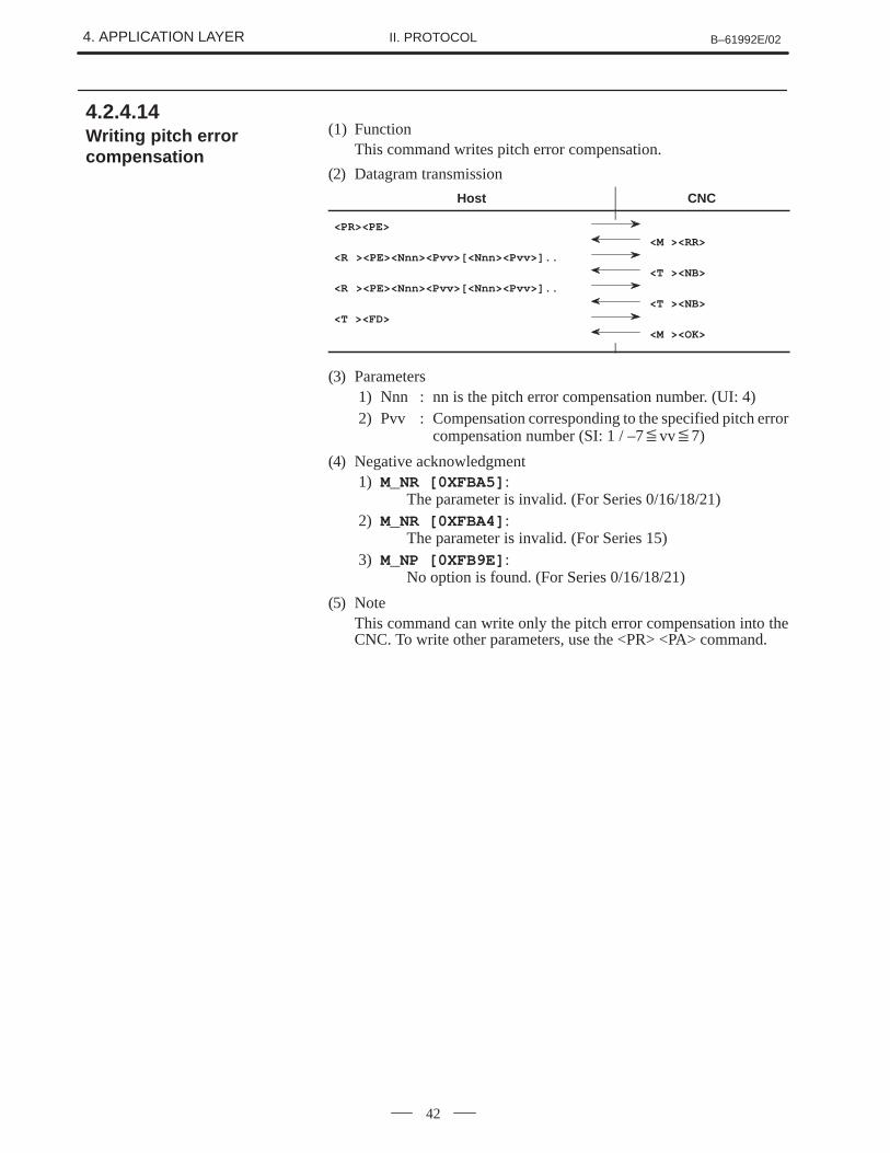
42
(1) FunctionThis command writes pitch error compensation.
(2) Datagram transmission
Host CNC
<PR><PE>
<M ><RR>
<R ><PE><Nnn><Pvv>[<Nnn><Pvv>]..
<T ><NB>
<R ><PE><Nnn><Pvv>[<Nnn><Pvv>]..
<T ><NB>
<T ><FD>
<M ><OK>
(3) Parameters1) Nnn : nn is the pitch error compensation number. (UI: 4)2) Pvv : Compensation corresponding to the specified pitch error
compensation number (SI: 1 / –7�vv�7)
(4) Negative acknowledgment1) M_NR [0XFBA5] :
The parameter is invalid. (For Series 0/16/18/21)2) M_NR [0XFBA4] :
The parameter is invalid. (For Series 15)3) M_NP [0XFB9E] :
No option is found. (For Series 0/16/18/21)
(5) NoteThis command can write only the pitch error compensation into theCNC. To write other parameters, use the <PR> <PA> command.
4.2.4.14 Writing pitch errorcompensation

B–61992E/02 4. APPLICATION LAYERII. PROTOCOL
43
(1) FunctionThis command reads a tool offset.
(2) Datagram transmission
Host CNC
<PT><TO><mm> [<:><nn> ]
<M ><RT>
<T ><NB>
<R ><TO> {<Nnn> <Dvv> [<Kvv>[<Hvv><Lvv]] (3)|<Xvv><Zvv><Rvv><Yvv><Qvv> (3)[<Uvv><Wvv><Pvv><Vvv>]>}.. (3)
<T > <NB>
<T ><FD>
<M > <OK>
(3) Parameters1) mm: First tool offset number to be read (UI: 4)2) nn : Last tool offset number to be read
(UI: 4 / 1�mm <nn�9999)3) kk : Offset request flag (HX: 4)
bit0 :Wear offset D : Cutter compensation1 :Geometry offset K : Cutter compensation2 :Wear offset X : Offset along the X axis3 :Wear offset Z : Offset along the Z axis4 :Wear offset R : Tool tip radius compensation5 :Wear offset Y : Offset along the Y axis6 :Virtual tool tip direction : Q7 :Not used8 :Wear offset H : Tool length offset9 :Geometry offset L : Tool length offset10 :Geometry offset U : Offset along the X axis11 :Geometry offset W : Offset along the Z axis12 :Geometry offset P : Tool tip radius compensation13 :Geometry offset V : Offset along the Y axis14 :Not used15 :Not used
NOTE(D, K, H, L) : Offsets for the milling machine(X, Z, R, Y, Q, U, W, P, V) : Offsets for the latheBoth the offset request flags must be mutually exclusivewhen they are set.Example) 0X3F00 : Incorrect
0X3C7C: Correct
4.2.4.15 Reading a tool offset
4. APPLICATION LAYER B–61992E/02II. PROTOCOL
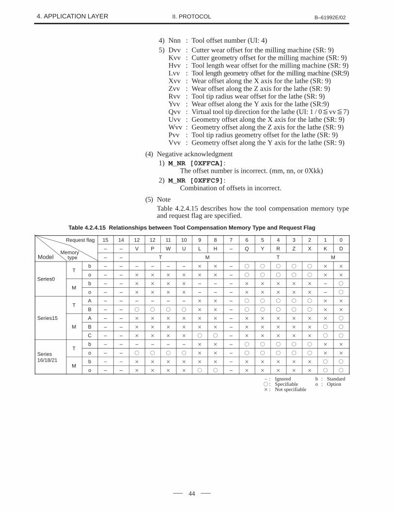
44
4) Nnn : Tool offset number (UI: 4)5) Dvv : Cutter wear offset for the milling machine (SR: 9)
Kvv : Cutter geometry offset for the milling machine (SR: 9)Hvv : Tool length wear offset for the milling machine (SR: 9)Lvv : Tool length geometry offset for the milling machine (SR:9)Xvv : Wear offset along the X axis for the lathe (SR: 9)Zvv : Wear offset along the Z axis for the lathe (SR: 9)Rvv : Tool tip radius wear offset for the lathe (SR: 9)Yvv : Wear offset along the Y axis for the lathe (SR:9)Qvv : Virtual tool tip direction for the lathe (UI: 1 / 0�vv�7)Uvv : Geometry offset along the X axis for the lathe (SR: 9)Wvv : Geometry offset along the Z axis for the lathe (SR: 9)Pvv : Tool tip radius geometry offset for the lathe (SR: 9)Vvv : Geometry offset along the Y axis for the lathe (SR: 9)
(4) Negative acknowledgment1) M_NR [0XFFCA] :
The offset number is incorrect. (mm, nn, or 0Xkk)2) M_NR [0XFFC9] :
Combination of offsets in incorrect.
(5) NoteTable 4.2.4.15 describes how the tool compensation memory typeand request flag are specified.
Table 4.2.4.15 Relationships between Tool Compensation Memory Type and Request Flag
15 14 12 12 11 10 9 8 7 6 5 4 3 2 1 0
– – V P W U L H – Q Y R Z X K D
– – T M T M
Tb – – – – – – � � – � � � � � � �
Series0
To – – � � � � � � – � � � � � � �
Series0
Mb – – � � � � – – – � � � � � – �
Mo – – � � � � – – – � � � � � – �
TA – – – – – – � � – � � � � � � �
TB – – � � � � � � – � � � � � � �
Series15 A – – � � � � � � – � � � � � � �
M B – – � � � � � � – � � � � � � �
C – – � � � � � � – � � � � � � �
Tb – – – – – – � � – � � � � � � �
SeriesT
o – – � � � � � � – � � � � � � �
16/18/21M
b – – � � � � � � – � � � � � � �M
o – – � � � � � � – � � � � � � �
– : Ignored b : Standard� : Specifiable o : Option� : Not specifiable
ModelMemory
type
Request flag
B–61992E/02 4. APPLICATION LAYERII. PROTOCOL
45
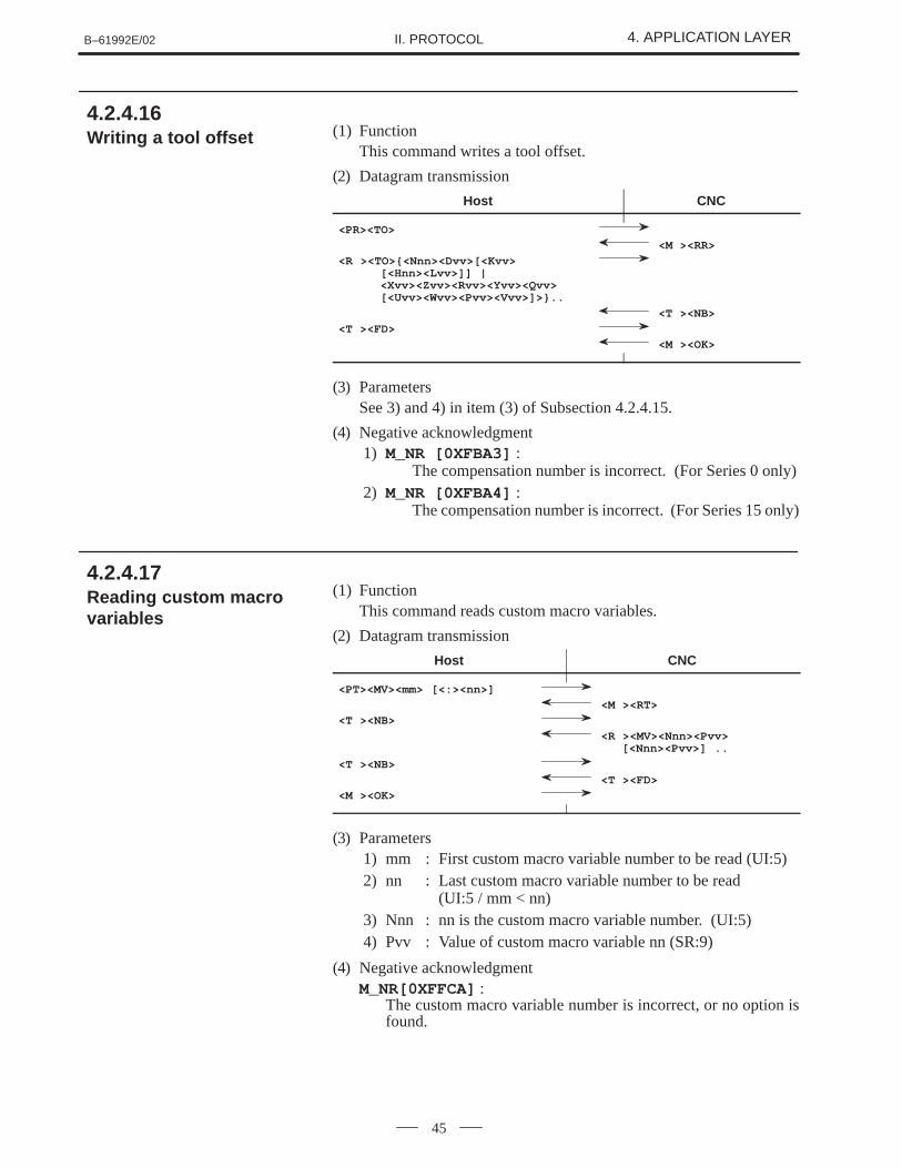
(1) FunctionThis command writes a tool offset.
(2) Datagram transmission
Host CNC
<PR><TO>
<M ><RR>
<R ><TO>{<Nnn><Dvv>[<Kvv>[<Hnn><Lvv>]] |<Xvv><Zvv><Rvv><Yvv><Qvv>[<Uvv><Wvv><Pvv><Vvv>]>}..
<T ><NB>
<T ><FD>
<M ><OK>
(3) ParametersSee 3) and 4) in item (3) of Subsection 4.2.4.15.
(4) Negative acknowledgment1) M_NR [0XFBA3] :
The compensation number is incorrect. (For Series 0 only)2) M_NR [0XFBA4] :
The compensation number is incorrect. (For Series 15 only)
(1) FunctionThis command reads custom macro variables.
(2) Datagram transmission
Host CNC
<PT><MV><mm> [<:><nn>]
<M ><RT>
<T ><NB>
<R ><MV><Nnn><Pvv> [<Nnn><Pvv>] ..
<T ><NB>
<T ><FD>
<M ><OK>
(3) Parameters1) mm : First custom macro variable number to be read (UI:5)2) nn : Last custom macro variable number to be read
(UI:5 / mm < nn)3) Nnn : nn is the custom macro variable number. (UI:5)4) Pvv : Value of custom macro variable nn (SR:9)
(4) Negative acknowledgmentM_NR[0XFFCA] :
The custom macro variable number is incorrect, or no option isfound.
4.2.4.16 Writing a tool offset
4.2.4.17 Reading custom macrovariables
4. APPLICATION LAYER B–61992E/02II. PROTOCOL
46
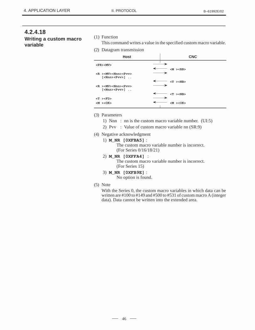
(1) FunctionThis command writes a value in the specified custom macro variable.
(2) Datagram transmission
Host CNC
<PR><MV>
<M ><RR>
<R ><MV><Nnn><Pvv>[<Nnn><Pvv>] ..
<T ><NB>
<R ><MV><Nnn><Pvv>[<Nnn><Pvv>] ..
<T ><NB>
<T ><FD>
<M ><OK> <M ><OK>
(3) Parameters1) Nnn : nn is the custom macro variable number. (UI:5)2) Pvv : Value of custom macro variable nn (SR:9)
(4) Negative acknowledgment1) M_NR [0XFBA5] :
The custom macro variable number is incorrect. (For Series 0/16/18/21)
2) M_NR [0XFFA4] : The custom macro variable number is incorrect. (For Series 15)
3) M_NR [0XFB9E] : No option is found.
(5) NoteWith the Series 0, the custom macro variables in which data can bewritten are #100 to #149 and #500 to #531 of custom macro A (integerdata). Data cannot be written into the extended area.
4.2.4.18 Writing a custom macrovariable
B–61992E/02 4. APPLICATION LAYERII. PROTOCOL
47
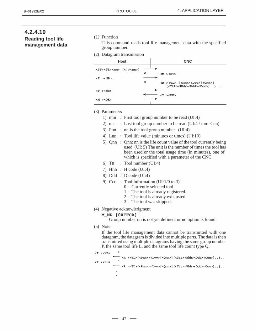
(1) FunctionThis command reads tool life management data with the specifiedgroup number.
(2) Datagram transmission
Host CNC
<PT><TL><mm> [<:><nn>]
<M ><RT>
<T ><NB>
<R ><TL> {<Pnn><Lvv>[<Qnn>][<Ttt><Hhh><Ddd><Ccc>]..} ..
<T ><NB>
<T ><FD>
<M ><OK>
(3) Parameters1) mm : First tool group number to be read (UI:4)2) nn : Last tool group number to be read (UI:4 / mm < nn)3) Pnn : nn is the tool group number. (UI:4)4) Lnn : Tool life value (minutes or times) (UI:10)5) Qnn : Qnn: nn is the life count value of the tool currently being
used. (UI: 5) The unit is the number of times the tool hasbeen used or the total usage time (in minutes), one of which is specified with a parameter of the CNC.
6) Ttt : Tool number (UI:4)7) Hhh : H code (UI:4)8) Ddd : D code (UI:4)9) Ccc : Tool information (UI:1/0 to 3)
0 : Currently selected tool1 : The tool is already registered.2 : The tool is already exhausted.3 : The tool was skipped.
(4) Negative acknowledgmentM_NR [0XFFCA] :
Group number nn is not yet defined, or no option is found.
(5) NoteIf the tool life management data cannot be transmitted with onedatagram, the datagram is divided into multiple parts. The data is thentransmitted using multiple datagrams having the same group numberP, the same tool life L, and the same tool life count type Q.
<T ><NB>
<R ><TL>{<Pnn><<Lvv>[<Qnn>][<Ttt><Hhh><Ddd><Ccc>]..}..
<T ><NB>
<R ><TL>{<Pnn><<Lvv>[<Qnn>][<Ttt><Hhh><Ddd><Ccc>]..}..
.
.
4.2.4.19 Reading tool lifemanagement data
4. APPLICATION LAYER B–61992E/02II. PROTOCOL
48
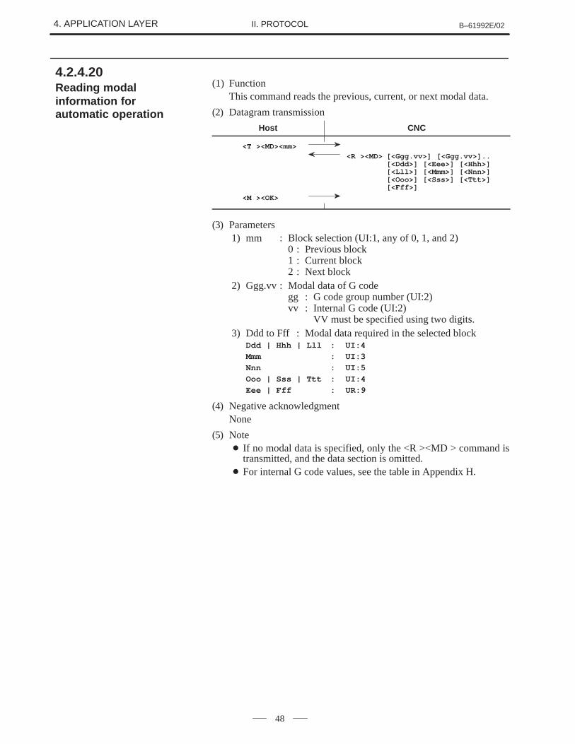
(1) FunctionThis command reads the previous, current, or next modal data.
(2) Datagram transmission
Host CNC
<T ><MD><mm>
<R ><MD> [<Ggg.vv>] [<Ggg.vv>]..[<Ddd>] [<Eee>] [<Hhh>][<Lll>] [<Mmm>] [<Nnn>][<Ooo>] [<Sss>] [<Ttt>][<Fff>]
<M ><OK>
(3) Parameters1) mm : Block selection (UI:1, any of 0, 1, and 2)
0 : Previous block1 : Current block2 : Next block
2) Ggg.vv : Modal data of G codegg : G code group number (UI:2)vv : Internal G code (UI:2)
VV must be specified using two digits.3) Ddd to Fff : Modal data required in the selected block
Ddd | Hhh | Lll : UI:4
Mmm : UI:3
Nnn : UI:5
Ooo | Sss | Ttt : UI:4
Eee | Fff : UR:9
(4) Negative acknowledgmentNone
(5) Note� If no modal data is specified, only the <R ><MD > command is
transmitted, and the data section is omitted.� For internal G code values, see the table in Appendix H.
4.2.4.20 Reading modalinformation forautomatic operation
B–61992E/02 4. APPLICATION LAYERII. PROTOCOL
49
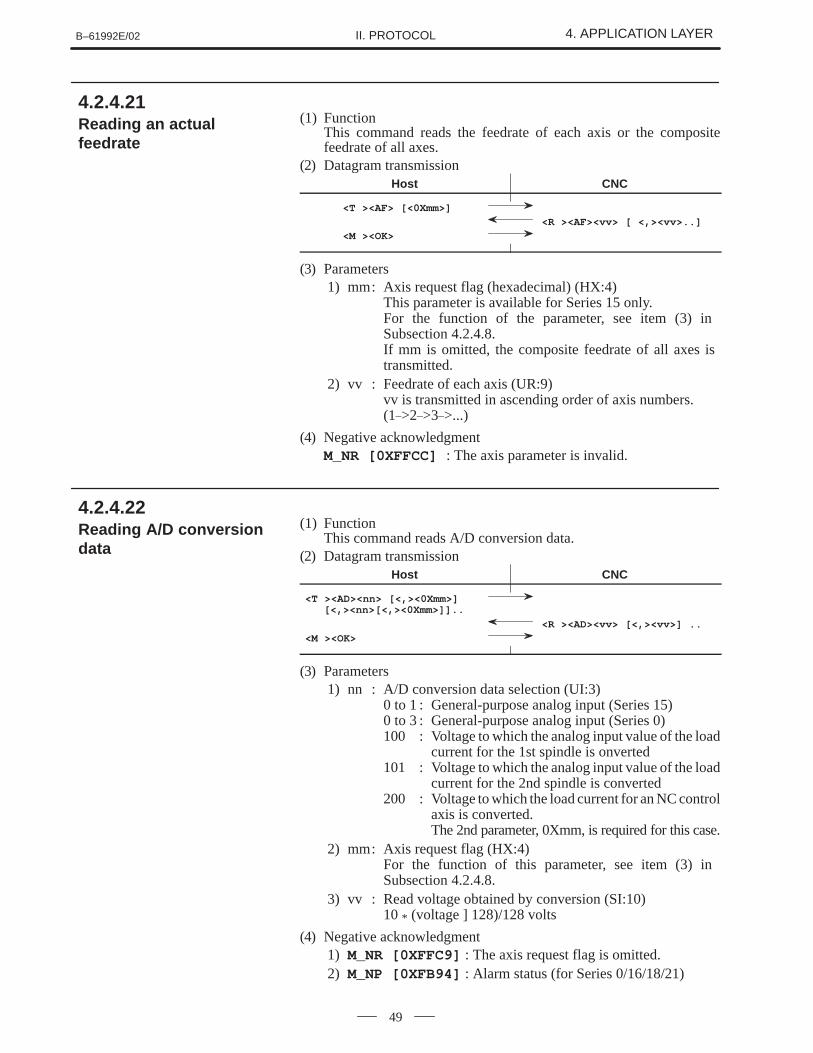
(1) FunctionThis command reads the feedrate of each axis or the compositefeedrate of all axes.
(2) Datagram transmissionHost CNC
<T ><AF> [<0Xmm>]
<R ><AF><vv> [ <,><vv>..]
<M ><OK>
(3) Parameters1) mm: Axis request flag (hexadecimal) (HX:4)
This parameter is available for Series 15 only.For the function of the parameter, see item (3) in Subsection 4.2.4.8.If mm is omitted, the composite feedrate of all axes is transmitted.
2) vv : Feedrate of each axis (UR:9)vv is transmitted in ascending order of axis numbers. (1_>2_>3_>...)
(4) Negative acknowledgmentM_NR [0XFFCC] : The axis parameter is invalid.
(1) FunctionThis command reads A/D conversion data.
(2) Datagram transmissionHost CNC
<T ><AD><nn> [<,><0Xmm>][<,><nn>[<,><0Xmm>]]..
<R ><AD><vv> [<,><vv>] ..
<M ><OK>
(3) Parameters1) nn : A/D conversion data selection (UI:3)
0 to 1 : General-purpose analog input (Series 15)0 to 3 : General-purpose analog input (Series 0)100 : Voltage to which the analog input value of the load
current for the 1st spindle is onverted101 : Voltage to which the analog input value of the load
current for the 2nd spindle is converted200 : Voltage to which the load current for an NC control
axis is converted.The 2nd parameter, 0Xmm, is required for this case.
2) mm: Axis request flag (HX:4)For the function of this parameter, see item (3) in Subsection 4.2.4.8.
3) vv : Read voltage obtained by conversion (SI:10)10 * (voltage ] 128)/128 volts
(4) Negative acknowledgment1) M_NR [0XFFC9] : The axis request flag is omitted.2) M_NP [0XFB94] : Alarm status (for Series 0/16/18/21)
4.2.4.21 Reading an actualfeedrate
4.2.4.22 Reading A/D conversiondata
4. APPLICATION LAYER B–61992E/02II. PROTOCOL
50
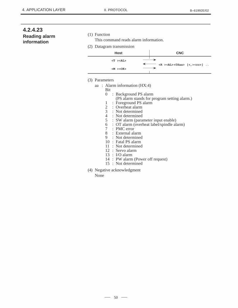
(1) FunctionThis command reads alarm information.
(2) Datagram transmission
Host CNC
<T ><AL>
<R ><AL><0Xaa> [<,><cc>] ..
<M ><OK>
(3) Parametersaa : Alarm information (HX:4)
Bit0 : Background PS alarm
(PS alarm stands for program setting alarm.)1 : Foreground PS alarm2 : Overheat alarm3 : Not determined4 : Not determined5 : SW alarm (parameter input enable)6 : OT alarm (overheat label/spindle alarm)7 : PMC error8 : External alarm9 : Not determined10 : Fatal PS alarm11 : Not determined 12 : Servo alarm13 : I/O alarm14 : PW alarm (Power off request)15 : Not determined
(4) Negative acknowledgmentNone
4.2.4.23 Reading alarminformation
B–61992E/02 4. APPLICATION LAYERII. PROTOCOL
51
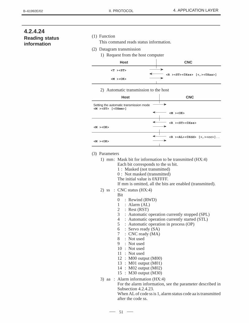
(1) FunctionThis command reads status information.
(2) Datagram transmission1) Request from the host computer
Host CNC
<T ><ST>
<R ><ST><0Xss> [<,><0Xaa>]
<M ><OK>
2) Automatic transmission to the host
Host CNC
Setting the automatic transmission mode<M ><ST> [<0Xmm>]
<M ><OK>
<R ><ST><0Xss>
<M ><OK>
<R ><AL><0Xdd> [<,><cc>]..
<M ><OK>
(3) Parameters1) mm: Mask bit for information to be transmitted (HX:4)
Each bit corresponds to the ss bit. 1 : Masked (not transmitted)0 : Not masked (transmitted)The initial value is 0XFFFF.If mm is omitted, all the bits are enabled (transmitted).
2) ss : CNC status (HX:4)Bit0 : Rewind (RWD)1 : Alarm (AL)2 : Rest (RST)3 : Automatic operation currently stopped (SPL)4 : Automatic operation currently started (STL)5 : Automatic operation in process (OP)6 : Servo ready (SA)7 : CNC ready (MA)8 : Not used9 : Not used10 : Not used11 : Not used12 : M00 output (M00)13 : M01 output (M01)14 : M02 output (M02)15 : M30 output (M30)
3) aa : Alarm information (HX:4)For the alarm information, see the parameter described inSubsection 4.2.4.23.When AL of code ss is 1, alarm status code aa is transmittedafter the code ss.
4.2.4.24 Reading statusinformation
4. APPLICATION LAYER B–61992E/02II. PROTOCOL
52
4) dd : Alarm information (HX:4)Value0 : Background PS alarm1 : Foreground PS alarm2 : Overheat alarm3 : Not determined4 : Not determined5 : SW alarm (parameter input enable)6 : OT alarm (overheat label/spindle alarm)7 : PMC error8 : External alarm9 : Not determinedA : Fatal PS alarmB : Not determined C : Servo alarmD : I/O alarmE : PW alarm (Power off request)F : Not determined10 : Battery alarm
(4) Negative acknowledgmentNone
(5) Notes1) In automatic notification mode, <R ><ST> or <R ><AL> is
automatically transmitted from the CNC.<R ><AL> is transmitted only when an alarm is issued.
2) In automatic notification mode, no commands other than<M><ST> can be transmitted from the host.
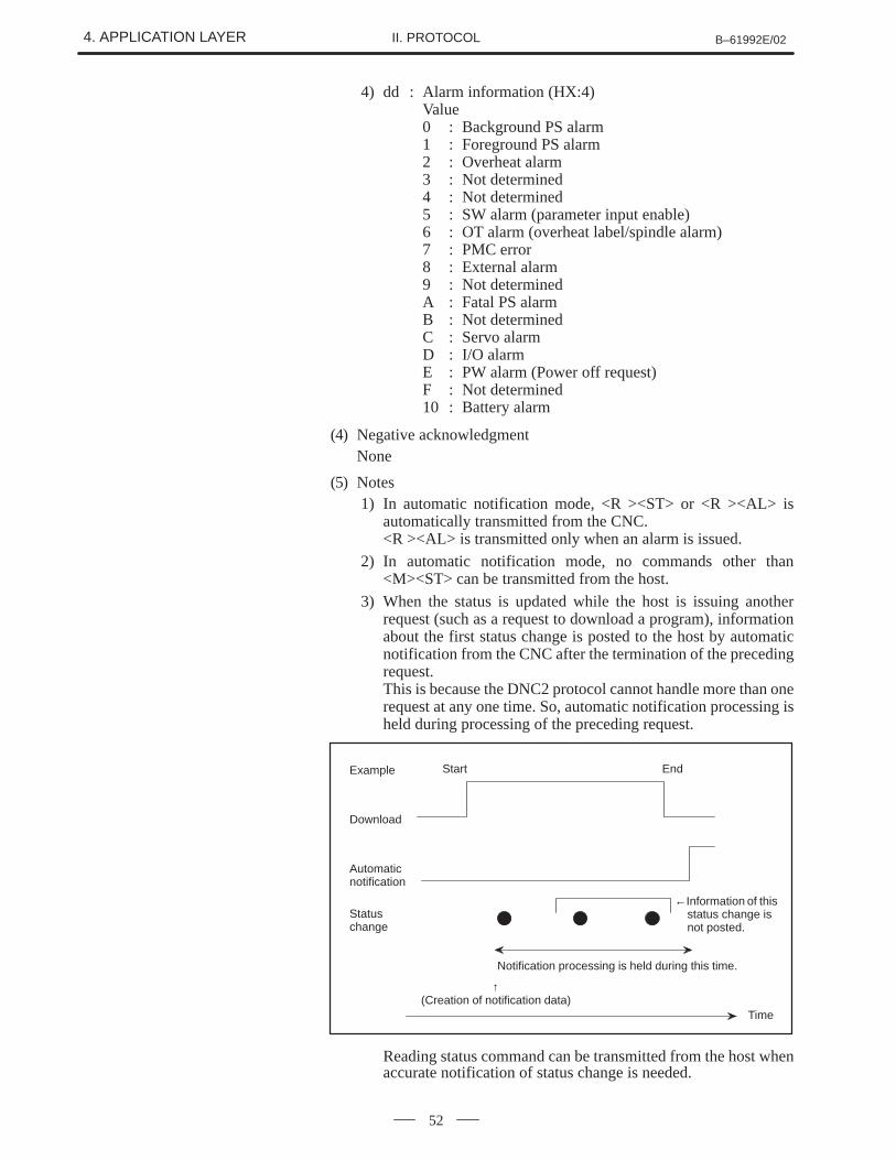
3) When the status is updated while the host is issuing anotherrequest (such as a request to download a program), informationabout the first status change is posted to the host by automaticnotification from the CNC after the termination of the precedingrequest.This is because the DNC2 protocol cannot handle more than onerequest at any one time. So, automatic notification processing isheld during processing of the preceding request.
Start EndExample
Download
Automaticnotification
Statuschange
Time
←Information of thisstatus change isnot posted.
Notification processing is held during this time.
↑(Creation of notification data)
Reading status command can be transmitted from the host whenaccurate notification of status change is needed.
B–61992E/02 4. APPLICATION LAYERII. PROTOCOL
53
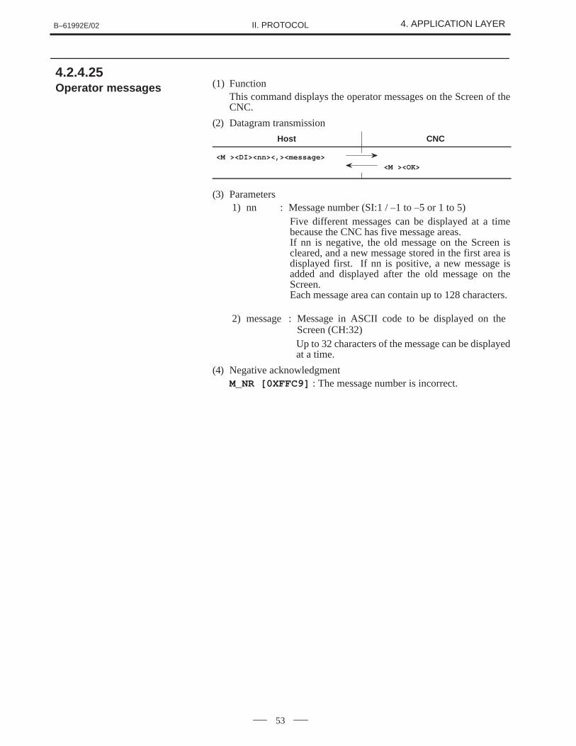
(1) FunctionThis command displays the operator messages on the Screen of theCNC.
(2) Datagram transmission
Host CNC
<M ><DI><nn><,><message>
<M ><OK>
(3) Parameters1) nn : Message number (SI:1 / –1 to –5 or 1 to 5)
Five different messages can be displayed at a timebecause the CNC has five message areas.If nn is negative, the old message on the Screen iscleared, and a new message stored in the first area isdisplayed first. If nn is positive, a new message isadded and displayed after the old message on theScreen.Each message area can contain up to 128 characters.
2) message : Message in ASCII code to be displayed on the Screen (CH:32)Up to 32 characters of the message can be displayedat a time.
(4) Negative acknowledgmentM_NR [0XFFC9] : The message number is incorrect.
4.2.4.25 Operator messages
4. APPLICATION LAYER B–61992E/02II. PROTOCOL
54
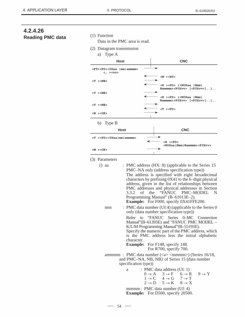
(1) FunctionData in the PMC area is read.
(2) Datagram transmissiona) Type A
Host CNC
<PT><PD><0Xaa |mm|ammmm><, ><nn>
<M ><RT>
<T ><NB>
<R ><PD> {<N0Xaa |Nmm|Nammmm><P0Xvv> [<P0Xvv>]..}..
<T ><NB>
<R ><PD> {<N0Xaa |Nmm|Nammmm><P0Xvv> [<P0Xvv>]..}..
<T ><NB>
<T ><FD>
<N ><OK>
b) Type B
Host CNC
<T ><PD><0Xaa|mm|ammmm>
<R ><PD><N0Xaa|Nmm|Nammmm><P0Xvv>
<M ><OK>
(3) Parameters1) aa : PMC address (HX: 8) (applicable to the Series 15
PMC–NA only (address specification type))The address is specified with eight hexadecimalcharacters by prefixing 0X41 to the 6–digit physicaladdress, given in the list of relationships betweenPMC addresses and physical addresses in Section3.3.2 of the “FANUC PMC–MODEL NProgramming Manual” (B–61013E–2).Example: For F000, specify 0X41FFE200.
mm : PMC data number (UI:4) (applicable to the Series 0only (data number specification type))Refer to “FANUC Series 0–MC ConnectionManual”(B–61393E) and “FANUC PMC MODEL –K/L/M Programming Manual”(B–55193E).Specify the numeric part of the PMC address, whichis the PMC address less the initial alphabeticcharacter.Example: For F148, specify 148.
For R700, specify 700.ammmm : PMC data number (<a> <mmmm>) (Series 16/18,
and PMC–NA, NB, NB2 of Series 15 (data number specification type))
a : PMC data address (UI: 1)0 � A 3 � F 6 � R 9 � Y1 � C 4 � G 7 � T2 � D 5 � K 8 � X
mmmm : PMC data number (UI: 4)Example: For D500, specify 20500.
4.2.4.26 Reading PMC data
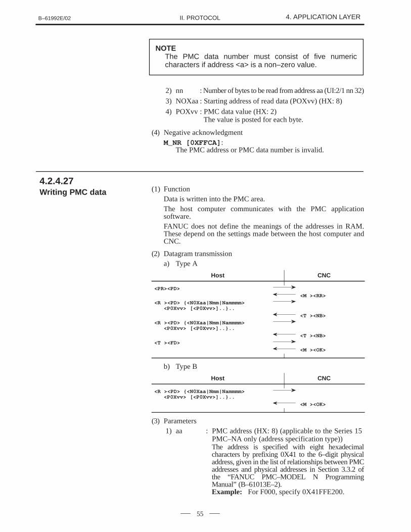
B–61992E/02 4. APPLICATION LAYERII. PROTOCOL
55
NOTEThe PMC data number must consist of five numericcharacters if address <a> is a non–zero value.
2) nn : Number of bytes to be read from address aa (UI:2/1 nn 32)
3) NOXaa : Starting address of read data (POXvv) (HX: 8)
4) POXvv : PMC data value (HX: 2) The value is posted for each byte.
(4) Negative acknowledgmentM_NR [0XFFCA] :
The PMC address or PMC data number is invalid.
(1) FunctionData is written into the PMC area.The host computer communicates with the PMC applicationsoftware.FANUC does not define the meanings of the addresses in RAM.These depend on the settings made between the host computer andCNC.
(2) Datagram transmissiona) Type A
Host CNC
<PR><PD>
<M ><RR>
<R ><PD> {<N0Xaa|Nmm|Nammmm> <P0Xvv> [<P0Xvv>]..}..
<T ><NB>
<R ><PD> {<N0Xaa|Nmm|Nammmm> <P0Xvv> [<P0Xvv>]..}..
<T ><NB>
<T ><FD>
<M ><OK>
b) Type B
Host CNC
<R ><PD> {<N0Xaa|Nmm|Nammmm> <P0Xvv> [<P0Xvv>]..}..
<M ><OK>
(3) Parameters1) aa : PMC address (HX: 8) (applicable to the Series 15
PMC–NA only (address specification type))The address is specified with eight hexadecimalcharacters by prefixing 0X41 to the 6–digit physicaladdress, given in the list of relationships between PMCaddresses and physical addresses in Section 3.3.2 ofthe “FANUC PMC–MODEL N ProgrammingManual” (B–61013E–2).Example: For F000, specify 0X41FFE200.
4.2.4.27 Writing PMC data
4. APPLICATION LAYER B–61992E/02II. PROTOCOL
56
mm : PMC data number (UI: 4) (applicable to the Series0 only (data number specification type))Refer to “FANUC Series 0–MC Connection Manual”(B–61393E) and “FANUC PMC MODEL–K/L/MProgramming Manual” (B–55193E).Specify the numeric part of the PMC address, whichis the PMC address less the initial alphabeticcharacter.Example: For F148, specify 148.
For R700, specify 700.ammmm : PMC data number (<a> <mmmm>) (Series 16/18,
and PMC–NA, NB, NB2 of Series 15 (data number specification type))
a : PMC data address (UI: 1)0 � A 3 � F 6 � R 9 � Y1 � C 4 � G 7 � T2 � D 5 � K 8 � X
mmmm : PMC data number (UI: 4)Example: For D500, specify 20500.
NOTEThe PMC data number must consist of five numericcharacters if address <a> is a non–zero value.
2) POXvv: Byte written in the PMC RAM (HX: 2)
(4) Negative acknowledgment1) M_NR [0XFFCA] :
The PMC address or PMC data number is invalid.2) M_NR [0XFBA3] :
The PMC address or PMC data number is beyond the allowable range.
(5) NoteIt is recommended that the data access direction for each PMC RAMbe determined explicitly between the host computer and PMC.Otherwise, when the host computer and PMC attempt to write datato the same RAM address at the same time, a contention occurs (if twounits attempt to write the same address at the same time, the writeprocessing being performed by one of the two units will fail).
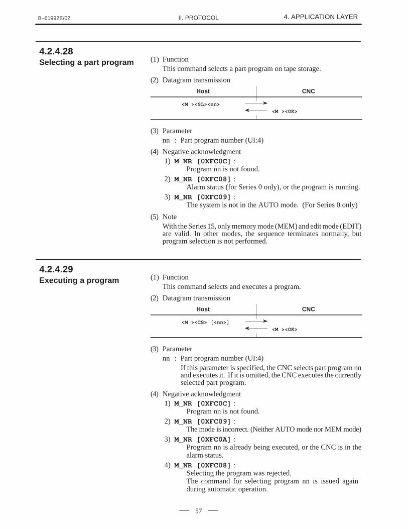
B–61992E/02 4. APPLICATION LAYERII. PROTOCOL
57
(1) FunctionThis command selects a part program on tape storage.
(2) Datagram transmission
Host CNC
<M ><SL><nn>
<M ><OK>
(3) Parameternn : Part program number (UI:4)
(4) Negative acknowledgment1) M_NR [0XFC0C] :
Program nn is not found.2) M_NR [0XFC08] :
Alarm status (for Series 0 only), or the program is running.3) M_NR [0XFC09] :
The system is not in the AUTO mode. (For Series 0 only)
(5) NoteWith the Series 15, only memory mode (MEM) and edit mode (EDIT)are valid. In other modes, the sequence terminates normally, butprogram selection is not performed.
(1) FunctionThis command selects and executes a program.
(2) Datagram transmission
Host CNC
<M ><CS> [<nn>]
<M ><OK>
(3) Parameternn : Part program number (UI:4)
If this parameter is specified, the CNC selects part program nnand executes it. If it is omitted, the CNC executes the currentlyselected part program.
(4) Negative acknowledgment1) M_NR [0XFC0C] :
Program nn is not found.2) M_NR [0XFC09] :
The mode is incorrect. (Neither AUTO mode nor MEM mode)3) M_NR [0XFC0A] :
Program nn is already being executed, or the CNC is in thealarm status.
4) M_NR [0XFC08] : Selecting the program was rejected.The command for selecting program nn is issued again during automatic operation.
4.2.4.28 Selecting a part program
4.2.4.29 Executing a program
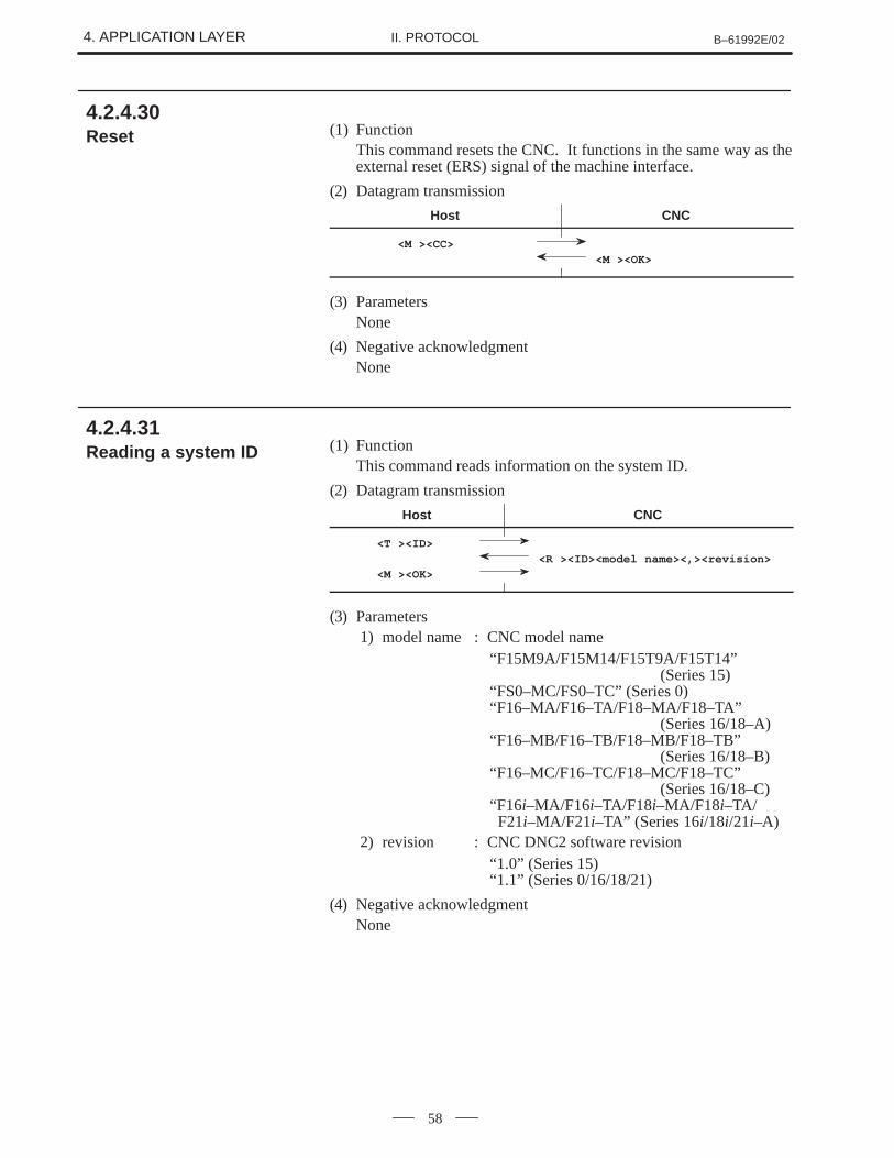
4. APPLICATION LAYER B–61992E/02II. PROTOCOL
58
(1) FunctionThis command resets the CNC. It functions in the same way as theexternal reset (ERS) signal of the machine interface.
(2) Datagram transmission
Host CNC
<M ><CC>
<M ><OK>
(3) ParametersNone
(4) Negative acknowledgmentNone
(1) FunctionThis command reads information on the system ID.
(2) Datagram transmission
Host CNC
<T ><ID>
<R ><ID><model name><,><revision>
<M ><OK>
(3) Parameters1) model name : CNC model name
“F15M9A/F15M14/F15T9A/F15T14” (Series 15)
“FS0–MC/FS0–TC” (Series 0)“F16–MA/F16–TA/F18–MA/F18–TA”
(Series 16/18–A)“F16–MB/F16–TB/F18–MB/F18–TB”
(Series 16/18–B)“F16–MC/F16–TC/F18–MC/F18–TC”
(Series 16/18–C)“F16i–MA/F16i–TA/F18i–MA/F18i–TA/ F21i–MA/F21i–TA” (Series 16i/18i/21i–A)
2) revision : CNC DNC2 software revision“1.0” (Series 15)“1.1” (Series 0/16/18/21)
(4) Negative acknowledgmentNone
4.2.4.30 Reset
4.2.4.31 Reading a system ID
B–61992E/02 4. APPLICATION LAYERII. PROTOCOL
59
This section describes the datagram protocol between the FANUC CNCand the host computer.
The DNC2 has six negative acknowledgments and one interruptcommand for handling errors.
(1) Syntax<T_BD | M_ER | M_NR | M_NP | T_NP | M_IL> [<0Xeeee>]
(2) FunctionsT_BD: Sent if the datagram protocol is incorrect. See Appendix D.M_ER: Sent if a syntax error is detected in the datagram.M_NR: Sent if the number given in the data section of the preceding
datagram is incorrect.M_NP: Sent if executing commands in the preceding datagram is
rejected.T_NP: Sent if the CNC cannot access the requested data.M_IL : Sent if errors other than the above occur.
(3) Error codeeeee : This four-digit hexadecimal code indicates the cause of the
error. The parameter specifies whether the code is output. See Appendixes B and F.
(4) ProtocolThe receiving device sends a negative acknowledgment to thesending device. The negative acknowledgment indicates that an erroroccurred in the receiving terminal.The device that sent the negative acknowledgment and the device thatreceived it must interrupt transmission immediately and return to theinitial state.
(1) Syntax<T_BD>
(2) FunctionThe interrupt command forcibly terminates processing currentlybeing transmitted. Either the CNC unit or the host computer can sendthis command at any time.
(3) ProtocolAs soon as the terminal receives the interrupt command, it interruptstransmission and returns to the initial state. When the terminal is inthe initial state, it ignores the interrupt command. This command isused to forcibly return the application layer to the initial state.
4.3DATAGRAMPROTOCOL
4.3.1Error Handling
4.3.1.1 Negativeacknowledgment
4.3.1.2 Interrupt command
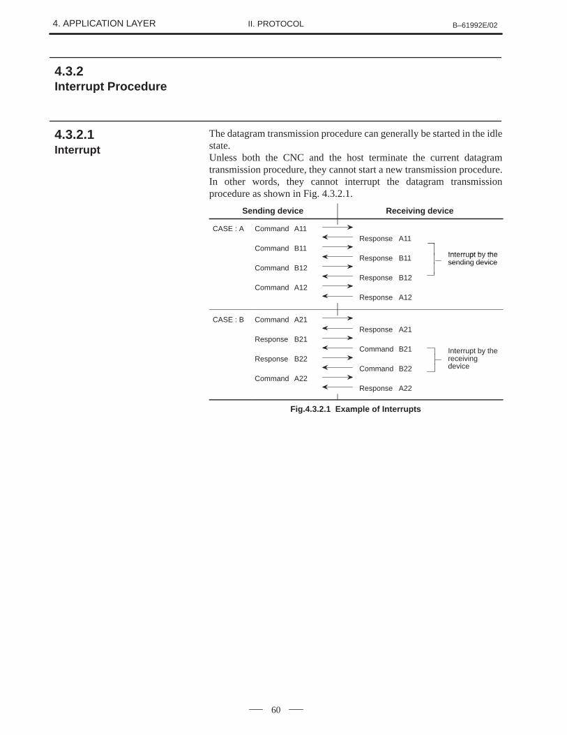
4. APPLICATION LAYER B–61992E/02II. PROTOCOL
60
The datagram transmission procedure can generally be started in the idlestate.Unless both the CNC and the host terminate the current datagramtransmission procedure, they cannot start a new transmission procedure.In other words, they cannot interrupt the datagram transmissionprocedure as shown in Fig. 4.3.2.1.
Sending device Receiving device
CASE : A Command A11Response A11
Command B11Interrupt by theResponse B11 Interrupt by thesending device
Command B12sending device
Response B12Command A12
Response A12
CASE : B Command A21Response A21
Response B21Command B21 Interrupt by the
Response B22y
receivingde iceCommand B22 device
Command A22Response A22
Fig.4.3.2.1 Example of Interrupts
4.3.2Interrupt Procedure
4.3.2.1 Interrupt

III. COMMUNICATION PROGRAMLIBRARY
B–61992E/02 1. OUTLINEIII. COMMUNICATION PROGRAM
LIBRARY
63
1 OUTLINE
This manual explains the use and installation of the communicationprogram library for a personal computer. They are specified in the DNC2protocol developed for DNC communication between a FANUC CNCand personal computer (PC), or between a CNC and host computer.
This library cannot be used on its own. Be sure to create applicationprograms and link them with this library. For creating and linkingapplication programs, see Section 3.3.
The demonstration program (sample application program) supplied withthis system permits simple control of the CNC.For use of the demonstration program, see Appendix K.
2. CONFIGURATION B–61992E/02III. COMMUNICATION PROGRAM
LIBRARY
64
2 CONFIGURATION
IBM PC series
Model : PC, AT, PS/2OS : PC–DOS Ver. 3.1 or laterCompiler: MS–C compiler Ver. 5.0 or laterMemory : The communication package library alone uses 134K
bytes of memory.Others : Use of the demonstration program requires the CGA
interface.
NEC PC–98 series
Model : Model VM and all subsequent models (except thehigh–resolution mode)
OS : MS–DOS Ver. 3.1 or laterCompiler: MS–C compiler Ver. 5.0 or laterMemory : The MS–DOS 3.1 system alone uses 60K bytes of
memory. The MS–DOS 3.3B system alone uses 89Kbytes of memory. The communication package libraryalone uses 134K bytes of memory.
Others : Only the RS–232–C standard port is supported.
Fujitsu FMR series
Model : FMR–50/60/70OS : MS–DOS Ver. 3.1 or laterCompiler: MS–C compiler Ver. 5.0 or laterMemory : The communication package library alone uses 134K
bytes of memory.Others : The demonstration program is designed for high
resolution
NOTEMemory requirements vary somewhat depending onwhether the config.sys file contains the specifications offiles and buffers. Memory requirements are also increasedby the size of device drivers such as print.sys, if included.

B–61992E/02 3. ������������III. COMMUNICATION PROGRAM
LIBRARY
65
3 ������������
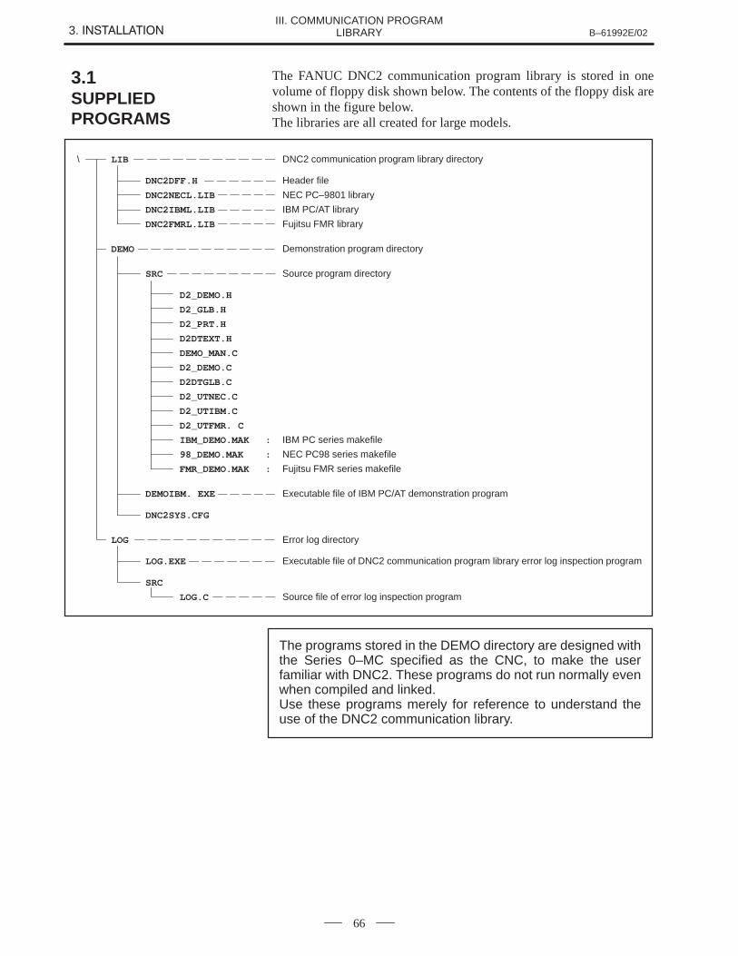
3. ������������ B–61992E/02III. COMMUNICATION PROGRAM
LIBRARY
66
The FANUC DNC2 communication program library is stored in onevolume of floppy disk shown below. The contents of the floppy disk areshown in the figure below.The libraries are all created for large models.
\ LIB DNC2 communication program library directory
DNC2DFF.H Header file
DNC2NECL.LIB NEC PC–9801 library
DNC2IBML.LIB IBM PC/AT library
DNC2FMRL.LIB Fujitsu FMR library
DEMO Demonstration program directory
SRC Source program directory
D2_DEMO.H
D2_GLB.H
D2_PRT.H
D2DTEXT.H
DEMO_MAN.C
D2_DEMO.C
D2DTGLB.C
D2_UTNEC.C
D2_UTIBM.C
D2_UTFMR. C
IBM_DEMO.MAK : IBM PC series makefile
98_DEMO.MAK : NEC PC98 series makefile
FMR_DEMO.MAK : Fujitsu FMR series makefile
DEMOIBM. EXE Executable file of IBM PC/AT demonstration program
DNC2SYS.CFG
LOG Error log directory
LOG.EXE Executable file of DNC2 communication program library error log inspection program
SRC
LOG.C Source file of error log inspection program
The programs stored in the DEMO directory are designed withthe Series 0–MC specified as the CNC, to make the userfamiliar with DNC2. These programs do not run normally evenwhen compiled and linked.Use these programs merely for reference to understand theuse of the DNC2 communication library.
3.1SUPPLIEDPROGRAMS
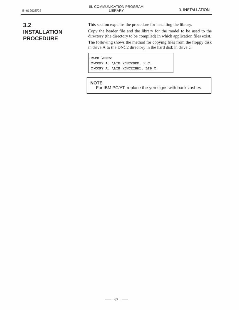
B–61992E/02 3. ������������III. COMMUNICATION PROGRAM
LIBRARY
67
This section explains the procedure for installing the library.
Copy the header file and the library for the model to be used to thedirectory (the directory to be compiled) in which application files exist.
The following shows the method for copying files from the floppy diskin drive A to the DNC2 directory in the hard disk in drive C.
C>CD \DNC2
C>COPY A: \LIB \DNC2DEF. H C:
C>COPY A: \LIB \DNC2IBML. LIB C:
NOTEFor IBM PC/AT, replace the yen signs with backslashes.
3.2INSTALLATIONPROCEDURE
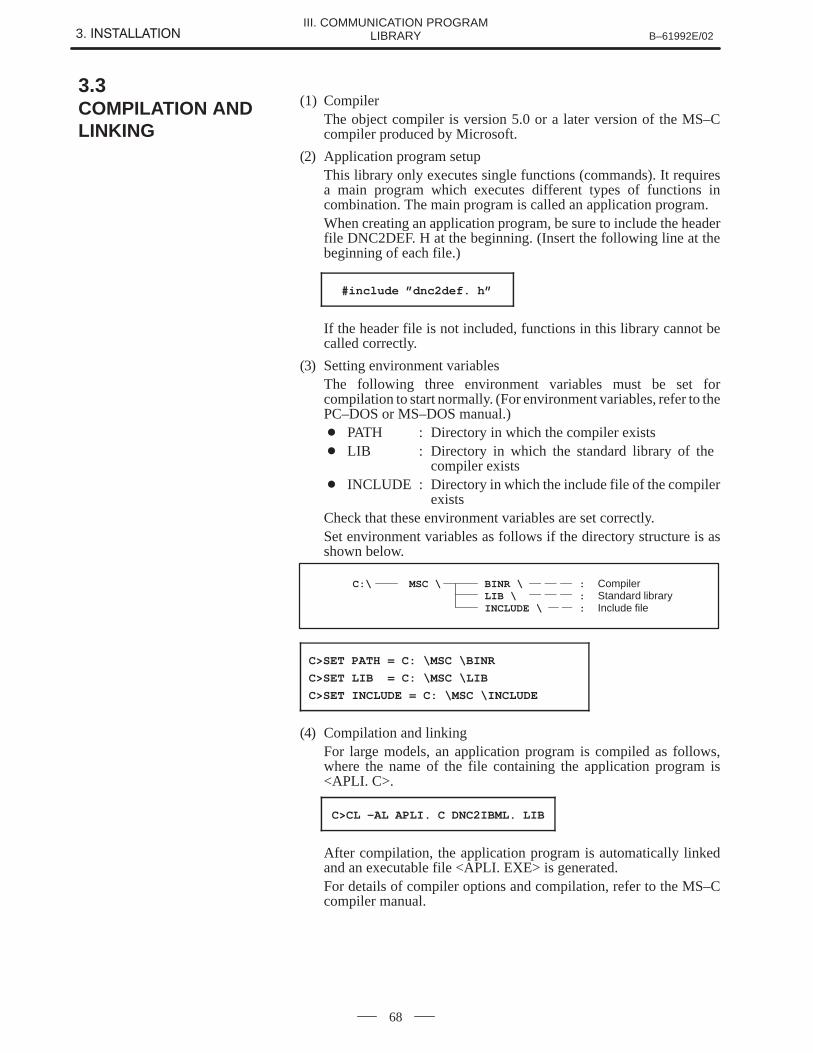
3. ������������ B–61992E/02III. COMMUNICATION PROGRAM
LIBRARY
68
(1) CompilerThe object compiler is version 5.0 or a later version of the MS–Ccompiler produced by Microsoft.
(2) Application program setupThis library only executes single functions (commands). It requiresa main program which executes different types of functions incombination. The main program is called an application program.When creating an application program, be sure to include the headerfile DNC2DEF. H at the beginning. (Insert the following line at thebeginning of each file.)
#include ”dnc2def. h”
If the header file is not included, functions in this library cannot becalled correctly.
(3) Setting environment variablesThe following three environment variables must be set forcompilation to start normally. (For environment variables, refer to thePC–DOS or MS–DOS manual.) � PATH : Directory in which the compiler exists � LIB : Directory in which the standard library of the
compiler exists � INCLUDE : Directory in which the include file of the compiler
existsCheck that these environment variables are set correctly.Set environment variables as follows if the directory structure is asshown below.
C:\ MSC \ BINR \ : CompilerLIB \ : Standard libraryINCLUDE \ : Include file
C>SET PATH = C: \MSC \BINR
C>SET LIB = C: \MSC \LIB
C>SET INCLUDE = C: \MSC \INCLUDE
(4) Compilation and linkingFor large models, an application program is compiled as follows,where the name of the file containing the application program is<APLI. C>.
C>CL –AL APLI. C DNC2IBML. LIB
After compilation, the application program is automatically linkedand an executable file <APLI. EXE> is generated.For details of compiler options and compilation, refer to the MS–Ccompiler manual.
3.3COMPILATION ANDLINKING

B–61992E/02 4. FUNCTION SPECIFICATIONSIII. COMMUNICATION PROGRAM
LIBRARY
69
4 FUNCTION SPECIFICATIONS
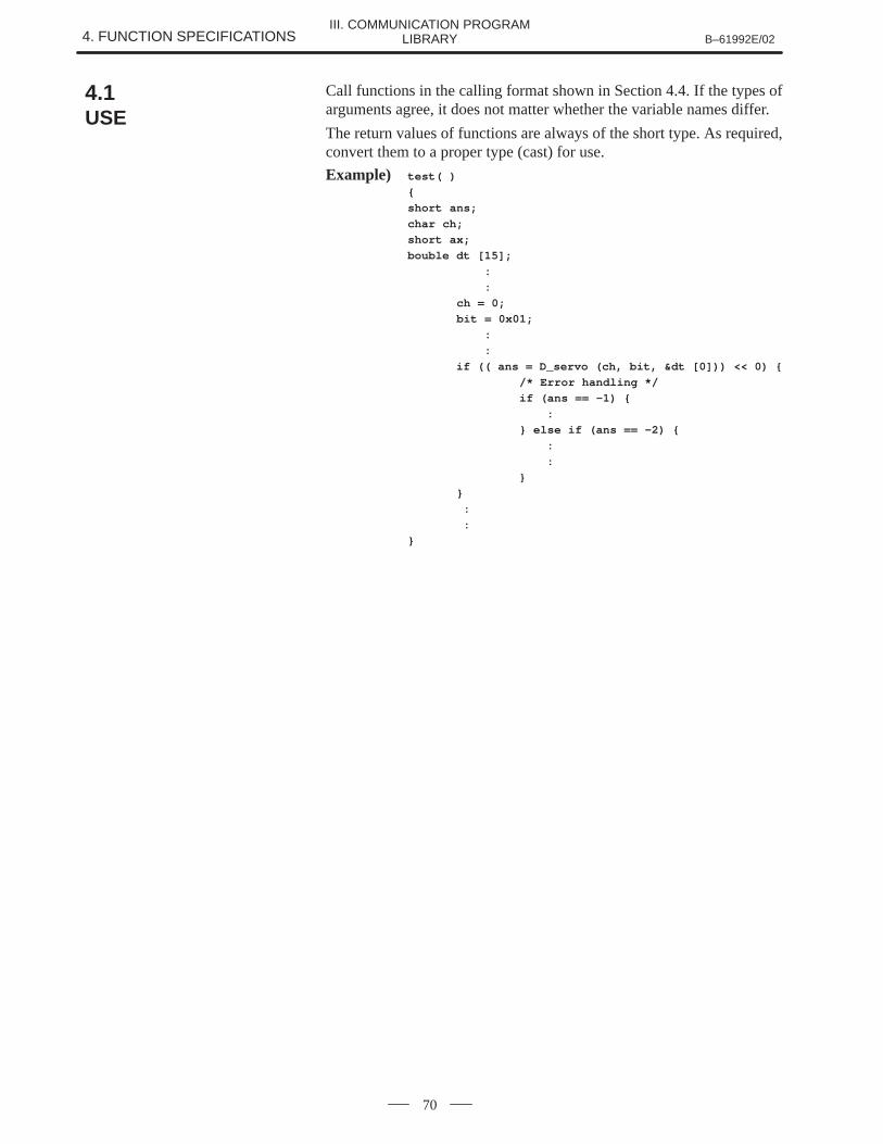
4. FUNCTION SPECIFICATIONS B–61992E/02III. COMMUNICATION PROGRAM
LIBRARY
70
Call functions in the calling format shown in Section 4.4. If the types ofarguments agree, it does not matter whether the variable names differ.
The return values of functions are always of the short type. As required,convert them to a proper type (cast) for use.
Example) test( )
{
short ans;
char ch;
short ax;
bouble dt [15];
:
:
ch = 0;
bit = 0x01;
:
:
if (( ans = D_servo (ch, bit, &dt [0])) << 0) {
/* Error handling */
if (ans == –1) {
:
} else if (ans == –2) {
:
:
}
}
:
:
}
4.1USE
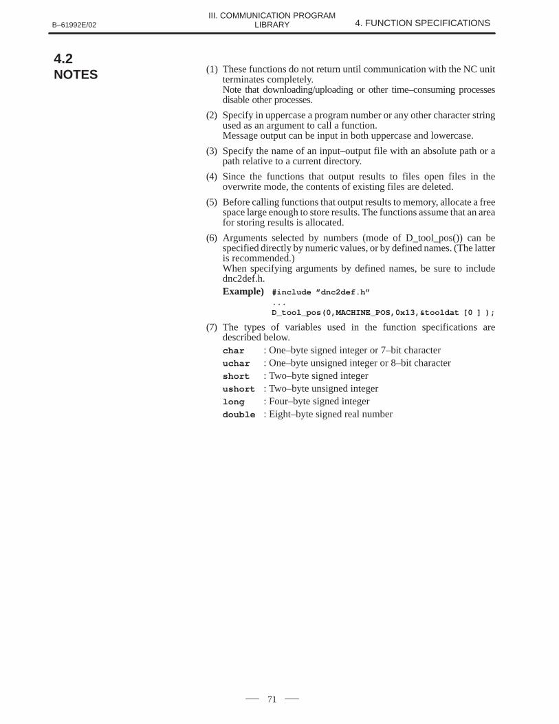
B–61992E/02 4. FUNCTION SPECIFICATIONSIII. COMMUNICATION PROGRAM
LIBRARY
71
(1) These functions do not return until communication with the NC unitterminates completely.Note that downloading/uploading or other time–consuming processesdisable other processes.
(2) Specify in uppercase a program number or any other character stringused as an argument to call a function.Message output can be input in both uppercase and lowercase.
(3) Specify the name of an input–output file with an absolute path or apath relative to a current directory.
(4) Since the functions that output results to files open files in theoverwrite mode, the contents of existing files are deleted.
(5) Before calling functions that output results to memory, allocate a freespace large enough to store results. The functions assume that an areafor storing results is allocated.
(6) Arguments selected by numbers (mode of D_tool_pos()) can bespecified directly by numeric values, or by defined names. (The latteris recommended.)When specifying arguments by defined names, be sure to includednc2def.h.Example) #include ”dnc2def.h”
...D_tool_pos(0,MACHINE_POS,0x13,&tooldat [0 ] );
(7) The types of variables used in the function specifications aredescribed below.char : One–byte signed integer or 7–bit characteruchar : One–byte unsigned integer or 8–bit charactershort : Two–byte signed integerushort : Two–byte unsigned integerlong : Four–byte signed integerdouble : Eight–byte signed real number
4.2NOTES
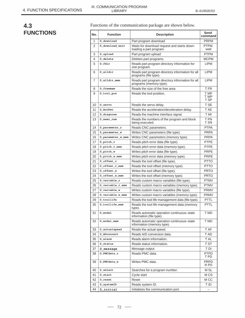
4. FUNCTION SPECIFICATIONS B–61992E/02III. COMMUNICATION PROGRAM
LIBRARY
72
Functions of the communication package are shown below.
No. Function Description Send command
1 D_download Part program download PRPM
2 D_download_wait Waits for download request and starts down-loading a part program.
PTPM wait
3 D_upload Part program upload PTPM
4 D_delete Deletes part programs. MCPM
5 D_fdir Reads part program directory information forone program.
LIPM
6 D_alldir Reads part program directory information for allprograms (file type).
LIPM
7 D_alldir_mem Reads part program directory information for allprograms (memory type).
LIPM
8 D_freemem Reads the size of the free area T FR
9 D_tool_pos Reads the tool position. T MPT WPT SP
10 D_servo Reads the servo delay. T SE
11 D_AccDec Reads the acceleration/deceleration delay. T AE
12 D_diagnose Reads the machine interface signal. T MI
13 D_exec_num Reads the numbers of the program and blockbeing executed.
T PNT SN
14 D_parameter_r Reads CNC parameters. PTPA
15 D_parameter_w Writes CNC parameters (file type). PRPA
16 D_parameter_w_mem Writes CNC parameters (memory type). PRPA
17 D_pitch_r Reads pitch error data (file type). PTPE
18 D_pitch_r_mem Reads pitch error data (memory type). PTPE
19 D_pitch_w Writes pitch error data (file type). PRPE
20 D_pitch_w_mem Writes pitch error data (memory type). PRPE
21 D_offset_r Reads the tool offset (file type). PTTO
22 D_offset_r_mem Reads the tool offset (memory type). PTTO
23 D_offset_w Writes the tool offset (file type). PRTO
24 D_offset_w_mem Writes the tool offset (memory type). PRTO
25 D_variable_r Reads custom macro variables (file type). PTMV
26 D_variable_r_mem Reads custom macro variables (memory type). PTMV
27 D_variable_w Writes custom macro variables (file type). PRMV
28 D_variable_w_mem Writes custom macro variables (memory type). PRMV
29 D_toollife Reads the tool life management data (file type). PTTL
30 D_toollife_mem Reads the tool life management data (memorytype).
PTTL
31 D_modal Reads automatic operation continuous–stateinformation (file type).
T MD
32 D_modal_mem Reads automatic operation continuous–stateinformation (memory type).
T MD
33 D_actualspeed Reads the actual speed. T AF
34 D_ADconcert Reads A/D conversion data. T AD
35 D_alarm Reads alarm information. T AL
36 D_status Reads status information. T ST
37 D_message Message output T DI
38 D_PMCdata_r Reads PMC data. PTPDT PD
39 D_PMCdata_w Writes PMC data. PRPDR PD
40 D_select Searches for a program number. M SL
41 D_start Cycle start M CS
42 D_reset Reset M CC
43 D_systemID Reads system ID. T ID
44 D_initial Initializes the communication port. –
4.3FUNCTIONS
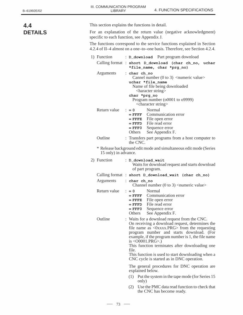
B–61992E/02 4. FUNCTION SPECIFICATIONSIII. COMMUNICATION PROGRAM
LIBRARY
73
This section explains the functions in detail.
For an explanation of the return value (negative acknowledgment)specific to each function, see Appendix J.
The functions correspond to the service functions explained in Section4.2.4 of II–4 almost on a one–to–one basis. Therefore, see Section 4.2.4.
1) Function : D_download Part program downloadCalling format : short D_download (char ch_no, uchar
*file_name, char *prg_no)
Arguments : char ch_noCannel number (0 to 3) <numeric value>
uchar *file_nameName of file being downloaded
<haracter string>char *prg_no
Program number (o0001 to o9999) <character string>
Return value := 0 Normal= FFFF Communication error= FFFE File open error= FFFD File read error= FFF0 Sequence errorOthers See Appendix F.
Outline : Transfers part programs from a host computer tothe CNC.
* Release background edit mode and simultaneous edit mode (Series15 only) in advance.
2) Function : D_download_wait Waits for download request and starts downloadof part program.
Calling format : short D_download_wait (char ch_no)
Arguments : char ch_noChannel number (0 to 3) <numeric value>
Return value := 0 Normal= FFFF Communication error= FFFE File open error= FFFD File read error= FFF0 Sequence errorOthers See Appendix F.
Outline : Waits for a download request from the CNC.On receiving a download request, determines thefile name as <0xxxx.PRG> from the requestingprogram number and starts download. (Forexample, if the program number is 1, the file nameis <O0001.PRG>.)This function terminates after downloading onefile.This function is used to start downloading when aCNC cycle is started as in DNC operation.
The general procedures for DNC operation areexplained below.(1) Put the system in the tape mode (for Series 15
only)(2) Use the PMC data read function to check that
the CNC has become ready.
4.4DETAILS
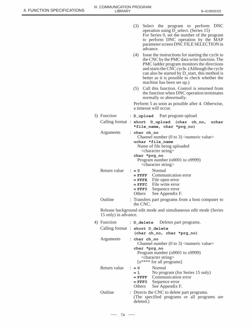
4. FUNCTION SPECIFICATIONS B–61992E/02III. COMMUNICATION PROGRAM
LIBRARY
74
(3) Select the program to perform DNCoperation using D_select. (Series 15)For Series 0, set the number of the programto perform DNC operation by the MAPparameter screen DNC FILE SELECTION inadvance.
(4) Issue the instructions for starting the cycle tothe CNC by the PMC data write function. ThePMC ladder program monitors the directionsand starts the CNC cycle. (Although the cyclecan also be started by D_start, this method isbetter as it is possible to check whether themachine has been set up.)
(5) Call this function. Control is returned fromthe function when DNC operation terminatesnormally or abnormally.
Perform 5 as soon as possible after 4. Otherwise,a timeout will occur.
3) Function : D_upload Part program uploadCalling format : short D_upload (char ch_no, uchar
*file_name, char *prg_no)
Arguments : char ch_noChannel number (0 to 3) <numeric value>
uchar *file_nameName of file being uploaded
<character string>char *prg_no
Program number (o0001 to o9999)<character string>
Return value := 0 Normal= FFFF Communication error= FFFE File open error= FFFC File write error= FFF0 Sequence errorOthers See Appendix F.
Outline : Transfers part programs from a host computer tothe CNC.
Release background edit mode and simultaneous edit mode (Series15 only) in advance.
4) Function : D_delete Deletes part programs.Calling format : short D_delete
(char ch_no, char *prg_no)
Arguments : char ch_noChannel number (0 to 3) <numeric value>
char *prg_noProgram number (o0001 to o9999)
<character string>[o**** for all programs]
Return value := 0 Normal= 1 No program (for Series 15 only)= FFFF Communication error= FFF0 Sequence errorOthers See Appendix F.
Outline : Directs the CNC to delete part programs.(The specified programs or all programs aredeleted.)
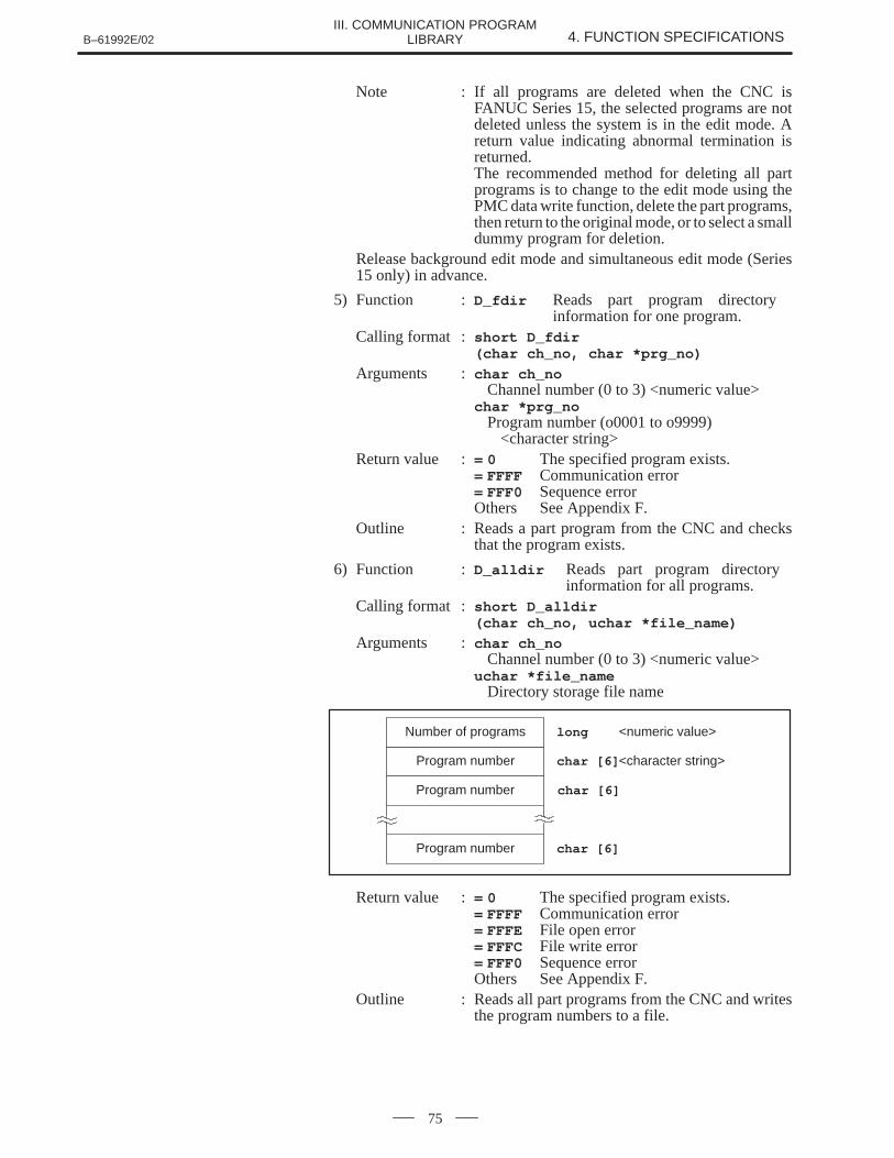
B–61992E/02 4. FUNCTION SPECIFICATIONSIII. COMMUNICATION PROGRAM
LIBRARY
75
Note : If all programs are deleted when the CNC isFANUC Series 15, the selected programs are notdeleted unless the system is in the edit mode. Areturn value indicating abnormal termination isreturned.The recommended method for deleting all partprograms is to change to the edit mode using thePMC data write function, delete the part programs,then return to the original mode, or to select a smalldummy program for deletion.
Release background edit mode and simultaneous edit mode (Series15 only) in advance.
5) Function : D_fdir Reads part program directory information for one program.
Calling format : short D_fdir (char ch_no, char *prg_no)
Arguments : char ch_noChannel number (0 to 3) <numeric value>
char *prg_noProgram number (o0001 to o9999)
<character string>Return value := 0 The specified program exists.
= FFFF Communication error= FFF0 Sequence errorOthers See Appendix F.
Outline : Reads a part program from the CNC and checksthat the program exists.
6) Function : D_alldir Reads part program directory information for all programs.
Calling format : short D_alldir (char ch_no, uchar *file_name)
Arguments : char ch_noChannel number (0 to 3) <numeric value>
uchar *file_nameDirectory storage file name
Program number
Program number
Program number
Number of programs
char [6] <character string>
char [6]
char [6]
long <numeric value>
Return value := 0 The specified program exists.= FFFF Communication error= FFFE File open error= FFFC File write error= FFF0 Sequence errorOthers See Appendix F.
Outline : Reads all part programs from the CNC and writesthe program numbers to a file.
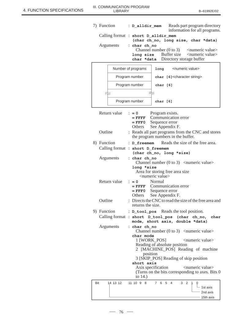
4. FUNCTION SPECIFICATIONS B–61992E/02III. COMMUNICATION PROGRAM
LIBRARY
76
7) Function : D_alldir_mem Reads part program directoryinformation for all programs.
Calling format : short D_alldir_mem (char ch_no, long size, char *data)
Arguments : char ch_noChannel number (0 to 3) <numeric value>
long size Buffer size <numeric value>char *data Directory storage buffer
Program number
Program number
Program number
Number of programs
char [6] <character string>
char [6]
char [6]
long <numeric value>
Return value := 0 Program exists.= FFFF Communication error= FFF0 Sequence errorOthers See Appendix F.
Outline : Reads all part programs from the CNC and storesthe program numbers in the buffer.
8) Function : D_freemem Reads the size of the free area.Calling format : short D_freemem
(char ch_no, long *size)Arguments : char ch_no
Channel number (0 to 3) <numeric value>long *size
Area for storing free area size<numeric value>
Return value := 0 Normal= FFFF Communication error= FFF0 Sequence errorOthers See Appendix F.
Outline : Directs the CNC to read the size of the free area andreturns the size.
9) Function : D_tool_pos Reads the tool position.Calling format : short D_tool_pos (char ch_no, char
mode, short axis, double *data)Arguments : char ch_no
Channel number (0 to 3) <numeric value>char mode
1 [WORK_POS] <numeric value>Reading of absolute position2 [MACHINE_POS] Reading of machine
position3 [SKIP_POS] Reading of skip position
short axisAxis specification <numeric value>(Turns on the bits corresponding to axes. Bits 0to 14.)
Bit 14 13 12 11 10 9 8 7 6 5 4 3 2 1 01st axis
2nd axis
15th axis
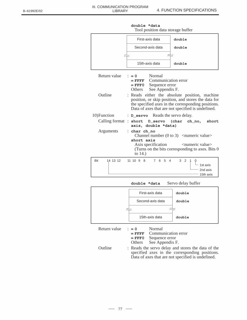
B–61992E/02 4. FUNCTION SPECIFICATIONSIII. COMMUNICATION PROGRAM
LIBRARY
77
double *dataTool position data storage buffer
First-axis data
Second-axis data
15th-axis data
double
double
double
Return value := 0 Normal= FFFF Communication error= FFF0 Sequence errorOthers See Appendix F.
Outline : Reads either the absolute position, machineposition, or skip position, and stores the data forthe specified axes in the corresponding positions.Data of axes that are not specified is undefined.
10)Function : D_servo Reads the servo delay.Calling format : short D_servo (char ch_no, short
axis, double *data)
Arguments : char ch_noChannel number (0 to 3) <numeric value>
short axisAxis specification <numeric value>(Turns on the bits corresponding to axes. Bits 0to 14.)
Bit 14 13 12 11 10 9 8 7 6 5 4 3 2 1 01st axis
2nd axis15th axis
double *data Servo delay buffer
First-axis data
Second-axis data
15th-axis data
double
double
double
Return value := 0 Normal= FFFF Communication error= FFF0 Sequence errorOthers See Appendix F.
Outline : Reads the servo delay and stores the data of thespecified axes in the corresponding positions.Data of axes that are not specified is undefined.
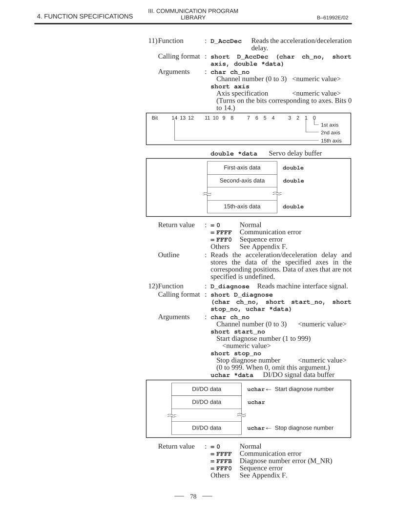
4. FUNCTION SPECIFICATIONS B–61992E/02III. COMMUNICATION PROGRAM
LIBRARY
78
11)Function : D_AccDec Reads the acceleration/decelerationdelay.
Calling format : short D_AccDec (char ch_no, shortaxis, double *data)
Arguments : char ch_noChannel number (0 to 3) <numeric value>
short axisAxis specification <numeric value>(Turns on the bits corresponding to axes. Bits 0to 14.)
Bit 14 13 12 11 10 9 8 7 6 5 4 3 2 1 01st axis
2nd axis
15th axis
double *data Servo delay buffer
First-axis data
Second-axis data
15th-axis data
double
double
double
Return value := 0 Normal= FFFF Communication error= FFF0 Sequence errorOthers See Appendix F.
Outline : Reads the acceleration/deceleration delay andstores the data of the specified axes in thecorresponding positions. Data of axes that are notspecified is undefined.
12)Function : D_diagnose Reads machine interface signal.Calling format : short D_diagnose
(char ch_no, short start_no, shortstop_no, uchar *data)
Arguments : char ch_noChannel number (0 to 3) <numeric value>
short start_noStart diagnose number (1 to 999)
<numeric value>short stop_no
Stop diagnose number <numeric value>(0 to 999. When 0, omit this argument.)
uchar *data DI/DO signal data buffer
DI/DO data
DI/DO data
DI/DO data
uchar � Start diagnose number
uchar
uchar � Stop diagnose number
Return value := 0 Normal= FFFF Communication error= FFFB Diagnose number error (M_NR)= FFF0 Sequence errorOthers See Appendix F.
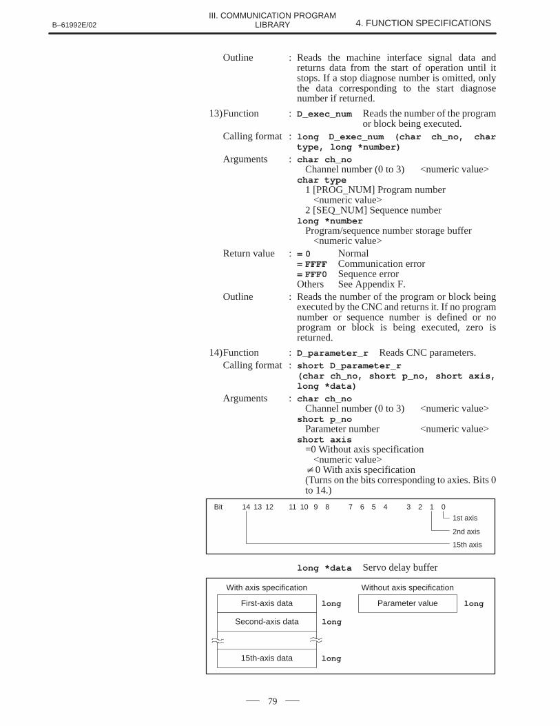
B–61992E/02 4. FUNCTION SPECIFICATIONSIII. COMMUNICATION PROGRAM
LIBRARY
79
Outline : Reads the machine interface signal data andreturns data from the start of operation until itstops. If a stop diagnose number is omitted, onlythe data corresponding to the start diagnosenumber if returned.
13)Function : D_exec_num Reads the number of the programor block being executed.
Calling format : long D_exec_num (char ch_no, chartype, long *number)
Arguments : char ch_noChannel number (0 to 3) <numeric value>
char type1 [PROG_NUM] Program number
<numeric value>2 [SEQ_NUM] Sequence number
long *numberProgram/sequence number storage buffer
<numeric value>Return value := 0 Normal
= FFFF Communication error= FFF0 Sequence errorOthers See Appendix F.
Outline : Reads the number of the program or block beingexecuted by the CNC and returns it. If no programnumber or sequence number is defined or noprogram or block is being executed, zero isreturned.
14)Function : D_parameter_r Reads CNC parameters.Calling format : short D_parameter_r
(char ch_no, short p_no, short axis,long *data)
Arguments : char ch_noChannel number (0 to 3) <numeric value>
short p_noParameter number <numeric value>
short axis=0 Without axis specification
<numeric value>�0 With axis specification(Turns on the bits corresponding to axies. Bits 0to 14.)
Bit 14 13 12 11 10 9 8 7 6 5 4 3 2 1 0
1st axis
2nd axis
15th axis
long *data Servo delay buffer
First-axis data
Second-axis data
15th-axis data
long
long
long
Parameter value long
With axis specification Without axis specification

4. FUNCTION SPECIFICATIONS B–61992E/02III. COMMUNICATION PROGRAM
LIBRARY
80
Return value := 0 Normal= FFFF Communication error= FFF0 Sequence errorOthers See Appendix F.
Outline : Directs the CNC to read CNC parameters andreturns the parameter or the parameterscorresponding to the specified axes. Data of axesthat are not specified is undefined.
15)Function : D_parameter_w Writes CNC parameters.Calling format : short D_parameter_w
(char ch_no, uchar *file_name)
Arguments : char ch_noChannel number (0 to 3) <numeric value>
uchar *file_nameName of write parameter file
Freelong_14
=0 Without axis specification�0 With axis specification (Turns on the bits corresponding
to the specified axies.)
shortParameter No.
shortAxis specification
Data
Data
Data CNCPARAM
Data
longFirst-axis data
Second-axis data
15th-axis data
With axis specificaiton
longParameter value
Without axis specification
No. of data items short
Axis specification Bit 14 13 12 11 10 9 8 7 6 5 4 3 2 1 01st axis
2nd axis
15th axistypedef struct {
short no;
short axis;
long dt [15]
} CNCPARAM;
Return value := 0 Normal= FFFF Communication error= FFFE File open error= FFFD File read error= FFF0 Sequence errorOthers See Appendix F.
Outline : Writes the parameters stored in the file or theparameters corresponding to the specified axes tothe CNC. Data of axes not specified is ignored.
Note : For the effective timing of updating parameters,refer to the CNC operator’s manual.
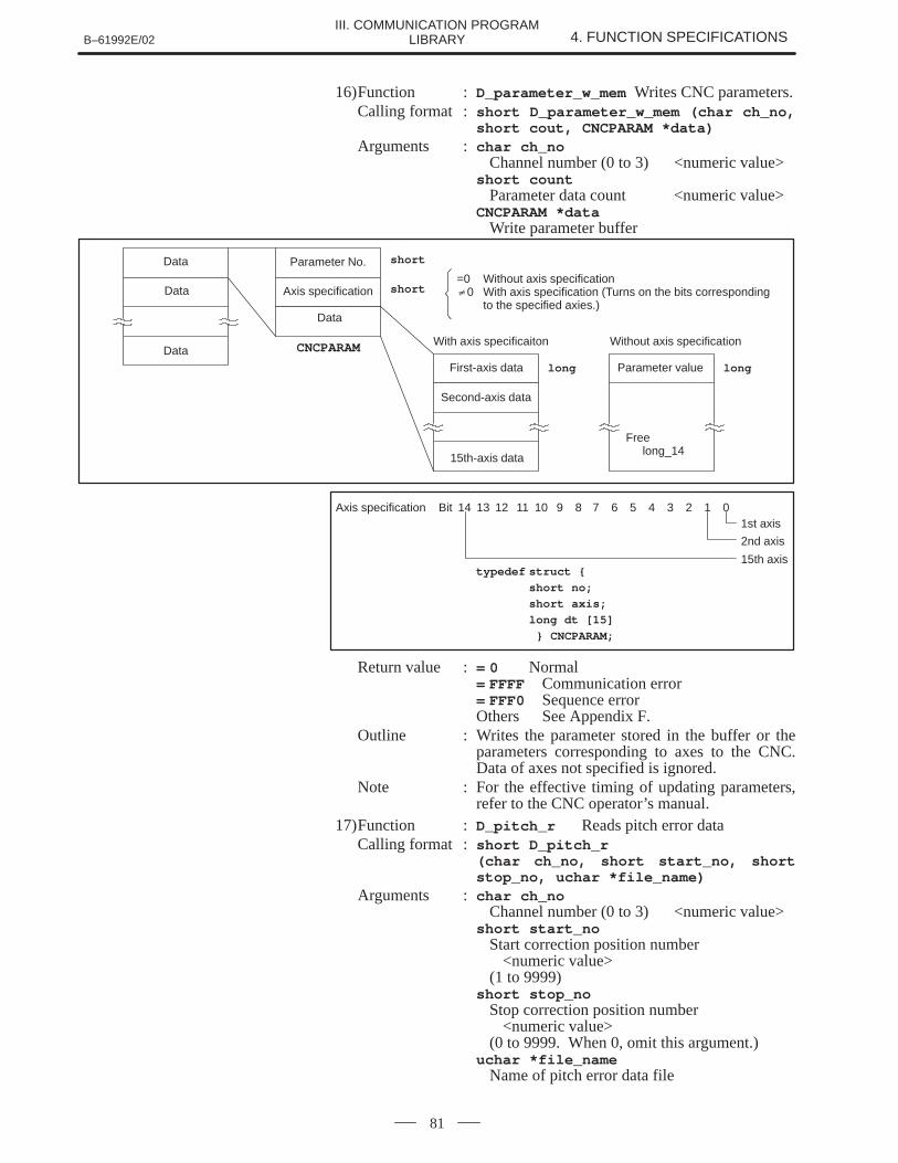
B–61992E/02 4. FUNCTION SPECIFICATIONSIII. COMMUNICATION PROGRAM
LIBRARY
81
16)Function : D_parameter_w_mem Writes CNC parameters.Calling format : short D_parameter_w_mem (char ch_no,
short cout, CNCPARAM *data)Arguments : char ch_no
Channel number (0 to 3) <numeric value>short count
Parameter data count <numeric value>CNCPARAM *data
Write parameter buffer
Freelong_14
=0 Without axis specification�0 With axis specification (Turns on the bits corresponding
to the specified axies.)
shortParameter No.
shortAxis specification
Data
Data
Data CNCPARAM
Data
longFirst-axis data
Second-axis data
15th-axis data
With axis specificaiton
longParameter value
Without axis specification
Axis specification Bit 14 13 12 11 10 9 8 7 6 5 4 3 2 1 01st axis
2nd axis
15th axistypedef struct {
short no;
short axis;
long dt [15]
} CNCPARAM;
Return value := 0 Normal= FFFF Communication error= FFF0 Sequence errorOthers See Appendix F.
Outline : Writes the parameter stored in the buffer or theparameters corresponding to axes to the CNC.Data of axes not specified is ignored.
Note : For the effective timing of updating parameters,refer to the CNC operator’s manual.
17)Function : D_pitch_r Reads pitch error dataCalling format : short D_pitch_r
(char ch_no, short start_no, shortstop_no, uchar *file_name)
Arguments : char ch_noChannel number (0 to 3) <numeric value>
short start_noStart correction position number
<numeric value>(1 to 9999)
short stop_noStop correction position number
<numeric value>(0 to 9999. When 0, omit this argument.)
uchar *file_nameName of pitch error data file
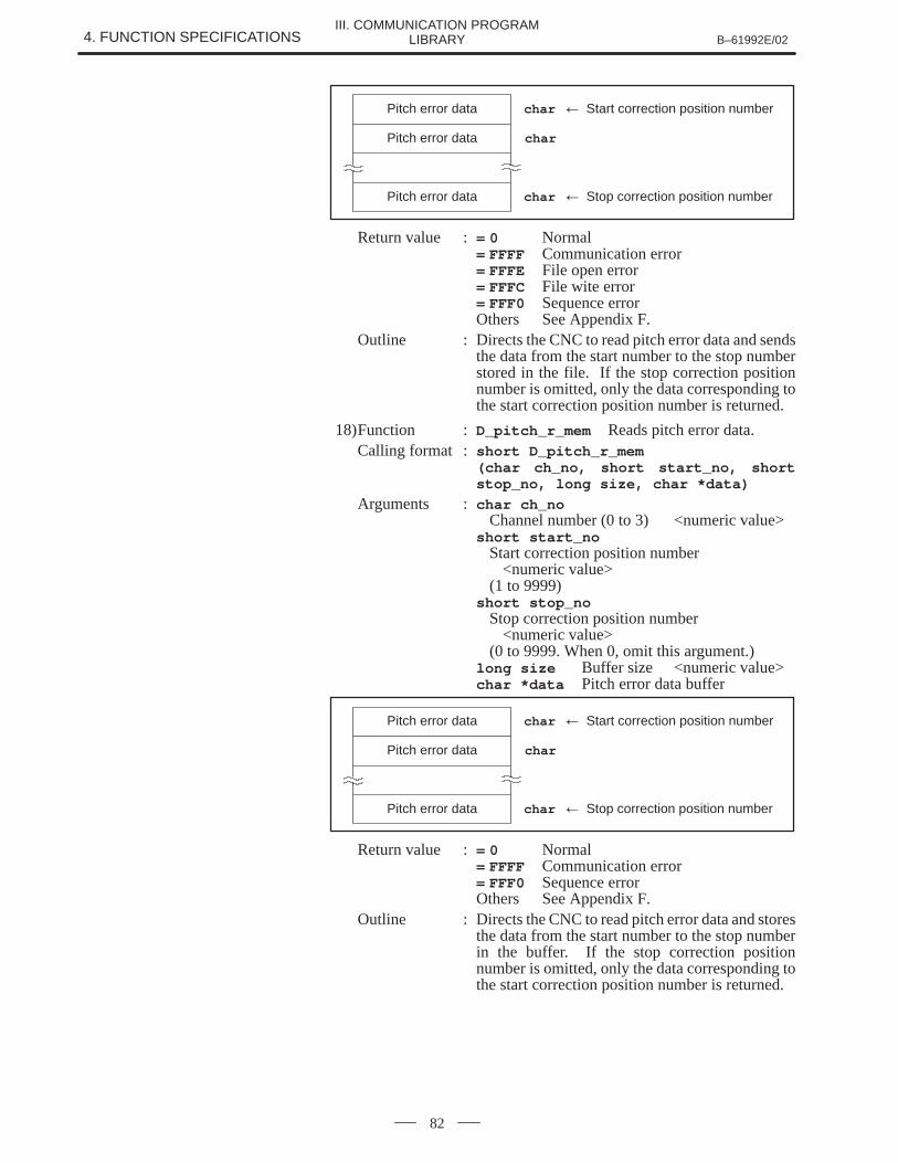
4. FUNCTION SPECIFICATIONS B–61992E/02III. COMMUNICATION PROGRAM
LIBRARY
82
Pitch error data
Pitch error data
Pitch error data
char � Start correction position number
char
char � Stop correction position number
Return value := 0 Normal= FFFF Communication error= FFFE File open error= FFFC File wite error= FFF0 Sequence errorOthers See Appendix F.
Outline : Directs the CNC to read pitch error data and sendsthe data from the start number to the stop numberstored in the file. If the stop correction positionnumber is omitted, only the data corresponding tothe start correction position number is returned.
18)Function : D_pitch_r_mem Reads pitch error data.Calling format : short D_pitch_r_mem
(char ch_no, short start_no, shortstop_no, long size, char *data)
Arguments : char ch_noChannel number (0 to 3) <numeric value>
short start_noStart correction position number
<numeric value>(1 to 9999)
short stop_noStop correction position number
<numeric value>(0 to 9999. When 0, omit this argument.)
long size Buffer size <numeric value>char *data Pitch error data buffer
Pitch error data
Pitch error data
Pitch error data
char � Start correction position number
char
char � Stop correction position number
Return value := 0 Normal= FFFF Communication error= FFF0 Sequence errorOthers See Appendix F.
Outline : Directs the CNC to read pitch error data and storesthe data from the start number to the stop numberin the buffer. If the stop correction positionnumber is omitted, only the data corresponding tothe start correction position number is returned.
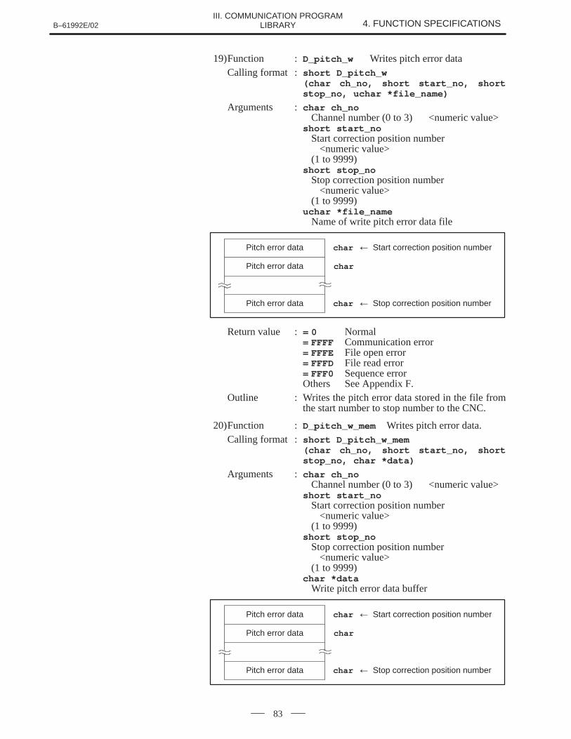
B–61992E/02 4. FUNCTION SPECIFICATIONSIII. COMMUNICATION PROGRAM
LIBRARY
83
19)Function : D_pitch_w Writes pitch error dataCalling format : short D_pitch_w
(char ch_no, short start_no, shortstop_no, uchar *file_name)
Arguments : char ch_noChannel number (0 to 3) <numeric value>
short start_noStart correction position number
<numeric value>(1 to 9999)
short stop_noStop correction position number
<numeric value>(1 to 9999)
uchar *file_nameName of write pitch error data file
Pitch error data
Pitch error data
Pitch error data
char � Start correction position number
char
char � Stop correction position number
Return value := 0 Normal= FFFF Communication error= FFFE File open error= FFFD File read error= FFF0 Sequence errorOthers See Appendix F.
Outline : Writes the pitch error data stored in the file fromthe start number to stop number to the CNC.
20)Function : D_pitch_w_mem Writes pitch error data.Calling format : short D_pitch_w_mem
(char ch_no, short start_no, shortstop_no, char *data)
Arguments : char ch_noChannel number (0 to 3) <numeric value>
short start_noStart correction position number
<numeric value>(1 to 9999)
short stop_noStop correction position number
<numeric value>(1 to 9999)
char *dataWrite pitch error data buffer
Pitch error data
Pitch error data
Pitch error data
char � Start correction position number
char
char � Stop correction position number
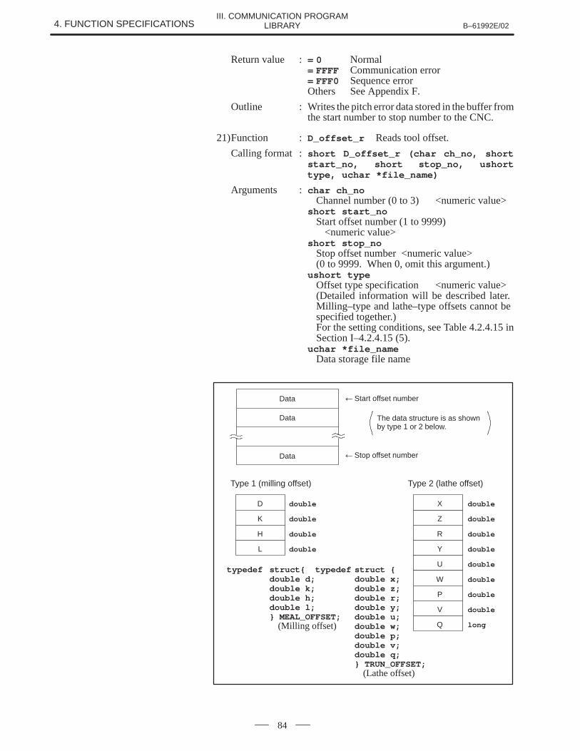
4. FUNCTION SPECIFICATIONS B–61992E/02III. COMMUNICATION PROGRAM
LIBRARY
84
Return value := 0 Normal= FFFF Communication error= FFF0 Sequence errorOthers See Appendix F.
Outline : Writes the pitch error data stored in the buffer fromthe start number to stop number to the CNC.
21)Function : D_offset_r Reads tool offset.
Calling format : short D_offset_r (char ch_no, shortstart_no, short stop_no, ushorttype, uchar *file_name)
Arguments : char ch_noChannel number (0 to 3) <numeric value>
short start_noStart offset number (1 to 9999)
<numeric value>short stop_no
Stop offset number <numeric value>(0 to 9999. When 0, omit this argument.)
ushort typeOffset type specification <numeric value>(Detailed information will be described later. Milling–type and lathe–type offsets cannot be specified together.)For the setting conditions, see Table 4.2.4.15 inSection I–4.2.4.15 (5).
uchar *file_nameData storage file name
� Start offset numberData
Data
� Stop offset numberData
The data structure is as shownby type 1 or 2 below.
Type 1 (milling offset)
doubleD
Type 2 (lathe offset)
doubleK
doubleH
doubleL
doubleZ
doubleR
doubleY
doubleU
doubleX
doubleW
doubleP
doubleV
longQ
typedef struct{ typedef struct {double d; double x;double k; double z;double h; double r;double l; double y;} MEAL_OFFSET; double u;
(Milling offset) double w;double p;double v;double q;} TRUN_OFFSET;
(Lathe offset)
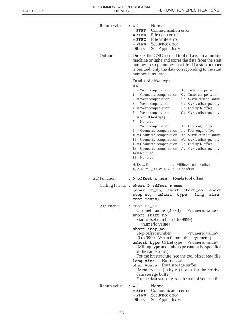
B–61992E/02 4. FUNCTION SPECIFICATIONSIII. COMMUNICATION PROGRAM
LIBRARY
85
Return value := 0 Normal= FFFF Communication error= FFFE File open error= FFFC File write error= FFF0 Sequence errorOthers See Appendix F.
Outline : Directs the CNC to read tool offsets on a millingmachine or lathe and stores the data from the startnumber to stop number in a file. If a stop numberis omitted, only the data corresponding to the startnumber is returned.
Details of offset typeBit0 = Wear compensation D : Cutter compensation1 = Geometric compensation K : Cutter compensation2 = Wear compensation X : X-axis offset quantity3 = Wear compensation Z : Z-axis offset quantity4 = Wear compensation R : Tool tip R offset5 = Wear compensation Y : Y-axis offset quantity6 = Virtual tool tipQ7 = Not used8 = Wear compensation H : Tool length offset9 = Geomertic compensation L : Tool length offset10 = Geomertic compensation U : X-axis offset quantity11 = Geomertic compensation W: Z-axis offset quantity12 = Geomertic compensation P : Tool tip R offset13 = Geomertic compensation V : Y-axis offset quantity14 = Not used15 = Not used
H, D, L, K : Milling machine offsetX, Z, R, Y, Q, U, W, P, V : Lathe offset
22)Function : D_offset_r_mem Reads tool offset.
Calling format : short D_offset_r_mem (char ch_no, short start_no, shortstop_no, ushort type, long size,char *data)
Arguments : char ch_noChannel number (0 to 3) <numeric value>
short start_noStart offset number (1 to 9999)
<numeric value>short stop_no
Stop offset number <numeric value>(0 to 9999. When 0, omit this argument.)
ushort type Offset type <numeric value>(Milling type and lathe type cannot be specifiedat the same time.)For the bit structure, see the tool offset read file.
long size Buffer sizechar *data Data storage buffer.
(Memory size (in bytes) usable for the receive data storage buffer)For the data structure, see the tool offset read file.
Return value := 0 Normal= FFFF Communication error= FFF0 Sequence errorOthers See Appendix F.
4. FUNCTION SPECIFICATIONS B–61992E/02III. COMMUNICATION PROGRAM
LIBRARY
86
Outline : Directs the CNC to read tool offsets on a millingmachine or lathe and stores the data from the startnumber to stop number in a file. If a stop numberis omitted, only the data corresponding to the startnumber is returned.
23)Function : D_offset_w Writes tool offset.Calling format : short D_offset_w (char ch_no, short
start_no, short stop_no, ushorttype, uchar *file_name)
Arguments : char ch_noChannel number (0 to 3) <numeric value>
short start_noStart coffset number (1 to 9999)
<numeric value>short stop_no
Stop offset number (1 to 9999)<numeric value>
ushort typeOffset type specification <numeric value>(Milling type and lathe type cannot be specifiedat the same time.)For the bit structure, see the tool offset read file.
uchar *file_nameWrite data storage file name.Only items specified in the offset type are written.For the data structure, see the tool offset read file.
NOTEThe offset type is specified for all write data. Be sure to inputthe data specified in type.
Return value := 0 Normal= FFFF Communication error= FFFE File open error= FFFD File read error= FFF0 Sequence errorOthers See Appendix F.
Outline : Writes the offsets on milling machines or lathesstored in a file from the start number to stopnumber to the CNC.
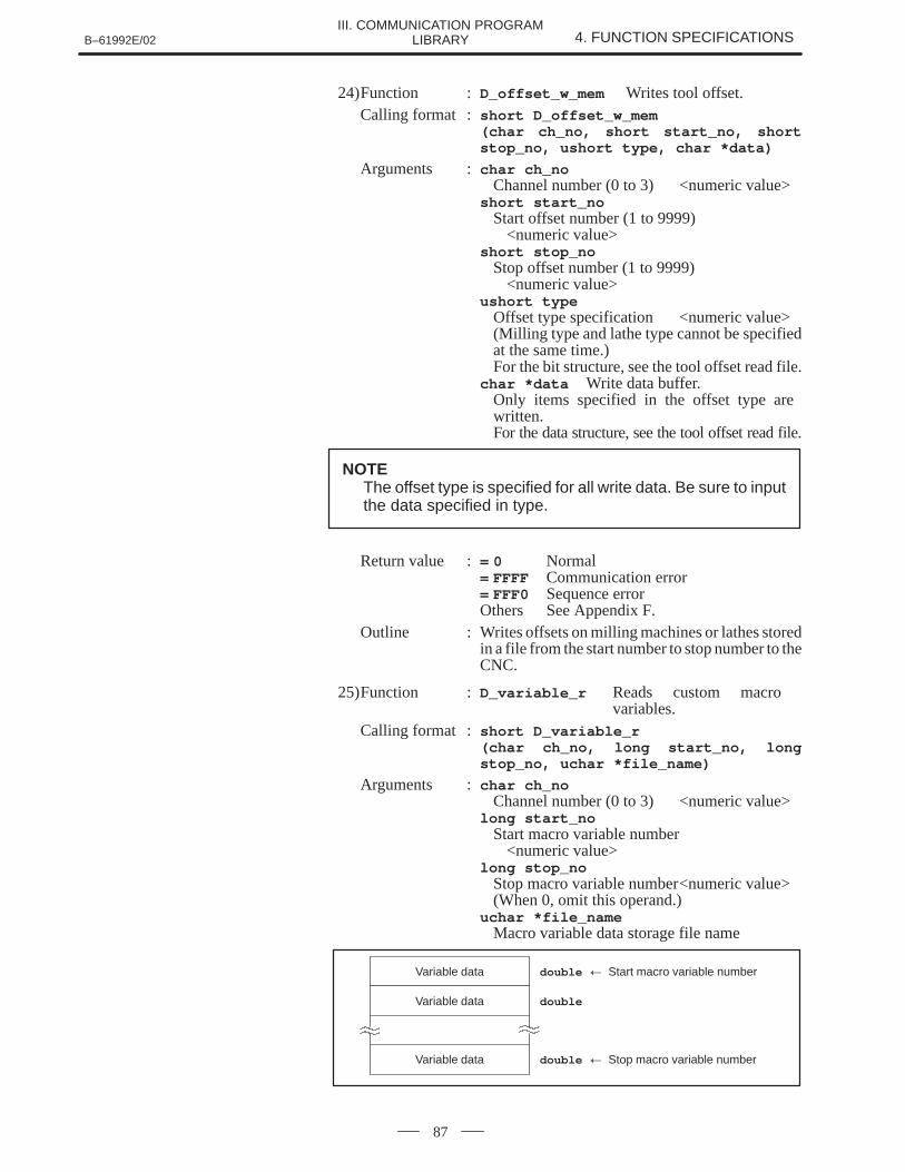
B–61992E/02 4. FUNCTION SPECIFICATIONSIII. COMMUNICATION PROGRAM
LIBRARY
87
24)Function : D_offset_w_mem Writes tool offset.Calling format : short D_offset_w_mem
(char ch_no, short start_no, shortstop_no, ushort type, char *data)
Arguments : char ch_noChannel number (0 to 3) <numeric value>
short start_noStart offset number (1 to 9999)
<numeric value>short stop_no
Stop offset number (1 to 9999)<numeric value>
ushort typeOffset type specification <numeric value>(Milling type and lathe type cannot be specifiedat the same time.)For the bit structure, see the tool offset read file.
char *data Write data buffer.Only items specified in the offset type are written.For the data structure, see the tool offset read file.
NOTEThe offset type is specified for all write data. Be sure to inputthe data specified in type.
Return value := 0 Normal= FFFF Communication error= FFF0 Sequence errorOthers See Appendix F.
Outline : Writes offsets on milling machines or lathes storedin a file from the start number to stop number to theCNC.
25)Function : D_variable_r Reads custom macro variables.
Calling format : short D_variable_r (char ch_no, long start_no, longstop_no, uchar *file_name)
Arguments : char ch_noChannel number (0 to 3) <numeric value>
long start_noStart macro variable number
<numeric value>long stop_no
Stop macro variable number<numeric value>(When 0, omit this operand.)
uchar *file_nameMacro variable data storage file name
double � Start macro variable numberVariable data
doubleVariable data
double � Stop macro variable numberVariable data
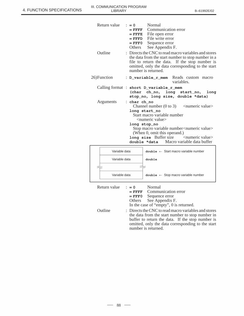
4. FUNCTION SPECIFICATIONS B–61992E/02III. COMMUNICATION PROGRAM
LIBRARY
88
Return value := 0 Normal= FFFF Communication error= FFFE File open error= FFFD File write error= FFF0 Sequence errorOthers See Appendix F.
Outline : Directs the CNC to read macro variables and storesthe data from the start number to stop number in afile to return the data. If the stop number isomitted, only the data corresponding to the startnumber is returned.
26)Function : D_variable_r_mem Reads custom macro variables.
Calling format : short D_variable_r_mem (char ch_no, long start_no, longstop_no, long size, double *data)
Arguments : char ch_noChannel number (0 to 3) <numeric value>
long start_noStart macro variable number
<numeric value>long stop_no
Stop macro variable number<numeric value>(When 0, omit this operand.)
long size Buffer size <numeric value>double *data Macro variable data buffer
double � Start macro variable numberVariable data
doubleVariable data
double � Stop macro variable numberVariable data
Return value := 0 Normal= FFFF Communication error= FFF0 Sequence errorOthers See Appendix F.In the case of “empty”, 0 is returned.
Outline : Directs the CNC to read macro variables and storesthe data from the start number to stop number inbuffer to return the data. If the stop number isomitted, only the data corresponding to the startnumber is returned.
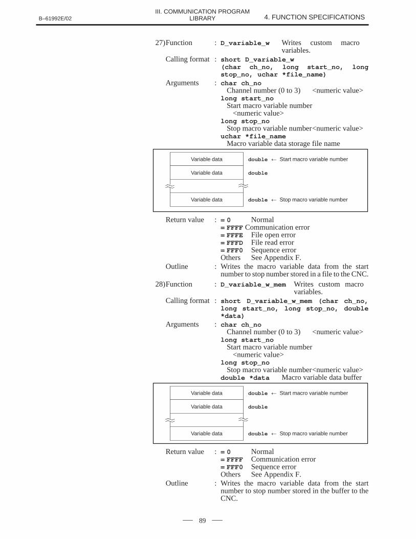
B–61992E/02 4. FUNCTION SPECIFICATIONSIII. COMMUNICATION PROGRAM
LIBRARY
89
27)Function : D_variable_w Writes custom macro variables.
Calling format : short D_variable_w (char ch_no, long start_no, longstop_no, uchar *file_name)
Arguments : char ch_noChannel number (0 to 3) <numeric value>
long start_noStart macro variable number
<numeric value>long stop_no
Stop macro variable number<numeric value>uchar *file_name
Macro variable data storage file name
double � Start macro variable numberVariable data
doubleVariable data
double � Stop macro variable numberVariable data
Return value := 0 Normal= FFFF Communication error= FFFE File open error= FFFD File read error= FFF0 Sequence errorOthers See Appendix F.
Outline : Writes the macro variable data from the startnumber to stop number stored in a file to the CNC.
28)Function : D_variable_w_mem Writes custom macro variables.
Calling format : short D_variable_w_mem (char ch_no,long start_no, long stop_no, double*data)
Arguments : char ch_noChannel number (0 to 3) <numeric value>
long start_noStart macro variable number
<numeric value>long stop_no
Stop macro variable number<numeric value>double *data Macro variable data buffer
double � Start macro variable numberVariable data
doubleVariable data
double � Stop macro variable numberVariable data
Return value := 0 Normal= FFFF Communication error= FFF0 Sequence errorOthers See Appendix F.
Outline : Writes the macro variable data from the startnumber to stop number stored in the buffer to theCNC.
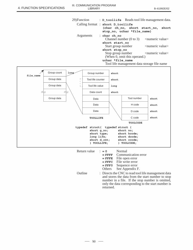
4. FUNCTION SPECIFICATIONS B–61992E/02III. COMMUNICATION PROGRAM
LIBRARY
90
29)Function : D_toollife Reads tool life management data.Calling format : short D_toollife
(char ch_no, short start_no, shortstop_no, uchar *file_name)
Arguments : char ch_noChannel number (0 to 3) <numeric value>
short start_noStart group number <numeric value>
short stop_noStop group number <numeric value>(When 0, omit this operand.)
uchar *file_nameTool life management data storage file name
file_nameshortGroup number
shortTool life counterGroup data
Group data
Group data
TOOLLIFE
Data
longTool life value
shortData count
Data
Data
shortTool number
shortH code
shortD code
TOOLCODE
shortC code
longGroup count
typedef struct{ typedef struct {short g_no; short no;short type; short hcode;long life; short dcode;short d_cnt; short ccode;} TOOLLIFE; } TOOLCODE;
Return value := 0 Normal= FFFF Communication error= FFFE File open error= FFFC File write error= FFF0 Sequence errorOthers See Appendix F.
Outline : Directs the CNC to read tool life management dataand stores the data from the start number to stopnumber in a file. If the stop number is omitted,only the data corresponding to the start number isreturned.
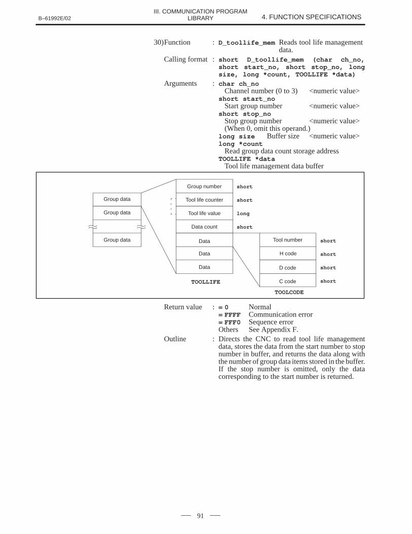
B–61992E/02 4. FUNCTION SPECIFICATIONSIII. COMMUNICATION PROGRAM
LIBRARY
91
30)Function : D_toollife_mem Reads tool life management data.
Calling format : short D_toollife_mem (char ch_no,short start_no, short stop_no, longsize, long *count, TOOLLIFE *data)
Arguments : char ch_noChannel number (0 to 3) <numeric value>
short start_noStart group number <numeric value>
short stop_noStop group number <numeric value>(When 0, omit this operand.)
long size Buffer size <numeric value>long *count
Read group data count storage addressTOOLLIFE *data
Tool life management data buffer
shortGroup number
shortTool life counterGroup data
Group data
Group data
TOOLLIFE
Data
longTool life value
shortData count
Data
Data
shortTool number
shortH code
shortD code
TOOLCODE
shortC code
Return value := 0 Normal= FFFF Communication error= FFF0 Sequence errorOthers See Appendix F.
Outline : Directs the CNC to read tool life managementdata, stores the data from the start number to stopnumber in buffer, and returns the data along withthe number of group data items stored in the buffer.If the stop number is omitted, only the datacorresponding to the start number is returned.
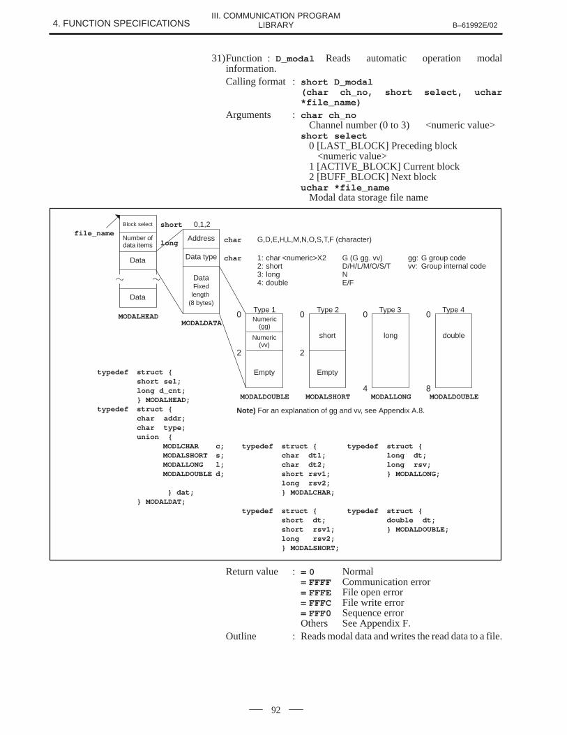
4. FUNCTION SPECIFICATIONS B–61992E/02III. COMMUNICATION PROGRAM
LIBRARY
92
31)Function : D_modal Reads automatic operation modalinformation.Calling format : short D_modal
(char ch_no, short select, uchar*file_name)
Arguments : char ch_noChannel number (0 to 3) <numeric value>
short select0 [LAST_BLOCK] Preceding block
<numeric value>1 [ACTIVE_BLOCK] Current block2 [BUFF_BLOCK] Next block
uchar *file_nameModal data storage file name
double
0
8MODALDOUBLE
long
0
4MODALLONG
short
0
2
MODALSHORT
Numeric(gg)
0
2
MODALDOUBLE
Numeric(vv)
Address
MODALDATA
Data type
Block select
Number ofdata items
Data
Data
EmptyEmpty
MODALHEAD
DataFixedlength
(8 bytes)
char G,D,E,H,L,M,N,O,S,T,F (character)
char 1: char <numeric>X2 G (G gg. vv) gg: G group code2: short D/H/L/M/O/S/T vv: Group internal code3: long N4: double E/F
short 0,1,2
long
file_name
Type 1 Type 2 Type 3 Type 4
Note) For an explanation of gg and vv, see Appendix A.8.
typedef struct {short sel;long d_cnt;} MODALHEAD;
typedef struct {char addr;char type;union {
MODLCHAR c; typedef struct { typedef struct {MODALSHORT s; char dt1; long dt;MODALLONG l; char dt2; long rsv;MODALDOUBLE d; short rsv1; } MODALLONG;
long rsv2; } dat; } MODALCHAR;
} MODALDAT;typedef struct { typedef struct {
short dt; double dt;short rsv1; } MODALDOUBLE;long rsv2;} MODALSHORT;
Return value := 0 Normal= FFFF Communication error= FFFE File open error= FFFC File write error= FFF0 Sequence errorOthers See Appendix F.
Outline : Reads modal data and writes the read data to a file.
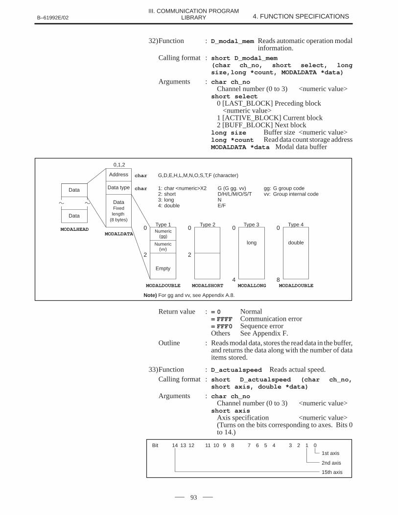
B–61992E/02 4. FUNCTION SPECIFICATIONSIII. COMMUNICATION PROGRAM
LIBRARY
93
32)Function : D_modal_mem Reads automatic operation modalinformation.
Calling format : short D_modal_mem (char ch_no, short select, longsize,long *count, MODALDATA *data)
Arguments : char ch_noChannel number (0 to 3) <numeric value>
short select0 [LAST_BLOCK] Preceding block
<numeric value>1 [ACTIVE_BLOCK] Current block2 [BUFF_BLOCK] Next block
long size Buffer size <numeric value>long *count Read data count storage addressMODALDATA *data Modal data buffer
double
0
8MODALDOUBLE
long
0
4MODALLONG
0
2
MODALSHORT
Numeric(gg)
0
2
MODALDOUBLE
Numeric(vv)
Address
MODALDATA
Data typeData
Data
Empty
MODALHEAD
DataFixedlength
(8 bytes)
char G,D,E,H,L,M,N,O,S,T,F (character)
char 1: char <numeric>X2 G (G gg. vv) gg: G group code2: short D/H/L/M/O/S/T vv: Group internal code3: long N4: double E/F
0,1,2
Type 1 Type 2 Type 3 Type 4
Note) For gg and vv, see Appendix A.8.
Return value := 0 Normal= FFFF Communication error= FFF0 Sequence errorOthers See Appendix F.
Outline : Reads modal data, stores the read data in the buffer,and returns the data along with the number of dataitems stored.
33)Function : D_actualspeed Reads actual speed.Calling format : short D_actualspeed (char ch_no,
short axis, double *data)
Arguments : char ch_noChannel number (0 to 3) <numeric value>
short axisAxis specification <numeric value>(Turns on the bits corresponding to axes. Bits 0to 14.)
Bit 14 13 12 11 10 9 8 7 6 5 4 3 2 1 0
1st axis
2nd axis
15th axis
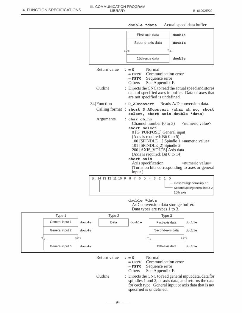
4. FUNCTION SPECIFICATIONS B–61992E/02III. COMMUNICATION PROGRAM
LIBRARY
94
double *data Actual speed data buffer
First-axis data
Second-axis data
15th-axis data
double
double
double
Return value := 0 Normal= FFFF Communication error= FFF0 Sequence errorOthers See Appendix F.
Outline : Directs the CNC to read the actual speed and storesdata of specified axes in buffer. Data of axes thatare not specified is undefined.
34)Function : D_ADconvert Reads A/D conversion data.Calling format : short D_ADconvert (char ch_no, short
select, short axis,double *data)
Arguments : char ch_noChannel number (0 to 3) <numeric value>
short select0 [G_PURPOSE] General input(Axis is required: Bit 0 to 5)100 [SPINDLE_1] Spindle 1 <numeric value>101 [SPINDLE_2) Spindle 2200 [AXIS_VOLTS] Axis data(Axis is required: Bit 0 to 14)
short axisAxis specification <numeric value>(Turns on bits corresponding to axes or generalinput.)
Bit 14 13 12 11 10 9 8 7 6 5 4 3 2 1 0
Fiest axis/general input 1
Second axis/general input 2
15th axis
double *dataA/D conversion data storage buffer.Data types are types 1 to 3.
Type 1
doubleGeneral input 1
doubleGeneral input 2
doubleGeneral input 6
Type 2
doubleData
Type 3
doubleFirst-axis data
doubleSecond-axis data
double15th-axis data
Return value := 0 Normal= FFFF Communication error= FFF0 Sequence errorOthers See Appendix F.
Outline : Directs the CNC to read general input data, data forspindles 1 and 2, or axis data, and returns the datafor each type. General input or axis data that is notspecified is undefined.
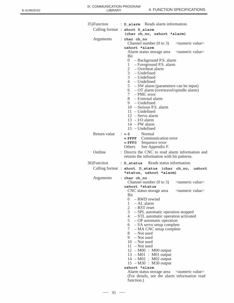
B–61992E/02 4. FUNCTION SPECIFICATIONSIII. COMMUNICATION PROGRAM
LIBRARY
95
35)Function : D_alarm Reads alarm information.Calling format : short D_alarm
(char ch_no, ushort *alarm)
Arguments : char ch_noChannel number (0 to 3) <numeric value>
ushort *alarmAlarm status storage area <numeric value>Bit0 – Background P.S. alarm1 – Foreground P.S. alarm2 – Overheat alarm3 – Undefined3 – Undefined4 – Undefined5 – SW alarm (parameters can be input)6 – OT alarm (overtravel/spindle alarm)7 – PMC error8 – External alarm9 – Undefined10 – Serious P.S. alarm11 – Undefined12 – Servo alarm13 – I/O alarm14 – PW alarm15 – Undefined
Return value := 0 Normal= FFFF Communication error= FFF0 Sequence errorOthers See Appendix F.
Outline : Directs the CNC to read alarm information andreturns the information with bit patterns.
36)Function : D_status Reads status information.Calling format : short D_status (char ch_no, ushort
*status, ushort *alarm)
Arguments : char ch_noChannel number (0 to 3) <numeric value>
ushort *statusCNC status storage area <numeric value>Bit0 – RWD rewind1 – AL alarm2 – RST reset3 – SPL automatic operation stopped4 – STL automatic operation activated5 – OP automatic operation6 – SA servo setup complete7 – MA CNC setup complete8 – Not used9 – Not used10 – Not used11 – Not used12 – M00 : M00 output13 – M01 : M01 output14 – M02 : M02 output15 – M30 : M30 output
ushort *alarmAlarm status storage area <numeric value>(For details, see the alarm information read function.)
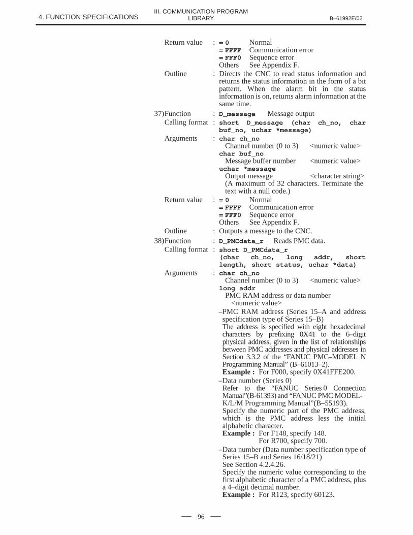
4. FUNCTION SPECIFICATIONS B–61992E/02III. COMMUNICATION PROGRAM
LIBRARY
96
Return value := 0 Normal= FFFF Communication error= FFF0 Sequence errorOthers See Appendix F.
Outline : Directs the CNC to read status information andreturns the status information in the form of a bitpattern. When the alarm bit in the statusinformation is on, returns alarm information at thesame time.
37)Function : D_message Message outputCalling format : short D_message (char ch_no, char
buf_no, uchar *message)Arguments : char ch_no
Channel number (0 to 3) <numeric value>char buf_no
Message buffer number <numeric value>uchar *message
Output message <character string>(A maximum of 32 characters. Terminate the text with a null code.)
Return value := 0 Normal= FFFF Communication error= FFF0 Sequence errorOthers See Appendix F.
Outline : Outputs a message to the CNC.38)Function : D_PMCdata_r Reads PMC data.
Calling format : short D_PMCdata_r (char ch_no, long addr, shortlength, short status, uchar *data)
Arguments : char ch_noChannel number (0 to 3) <numeric value>
long addrPMC RAM address or data number
<numeric value>–PMC RAM address (Series 15–A and addressspecification type of Series 15–B)The address is specified with eight hexadecimalcharacters by prefixing 0X41 to the 6–digitphysical address, given in the list of relationshipsbetween PMC addresses and physical addresses inSection 3.3.2 of the “FANUC PMC–MODEL NProgramming Manual” (B–61013–2).Example : For F000, specify 0X41FFE200.
–Data number (Series 0)Refer to the “FANUC Series 0 ConnectionManual”(B-61393) and “FANUC PMC MODEL-K/L/M Programming Manual”(B–55193).Specify the numeric part of the PMC address,which is the PMC address less the initialalphabetic character.Example : For F148, specify 148.
For R700, specify 700.–Data number (Data number specification type ofSeries 15–B and Series 16/18/21)See Section 4.2.4.26.Specify the numeric value corresponding to thefirst alphabetic character of a PMC address, plusa 4–digit decimal number.Example : For R123, specify 60123.
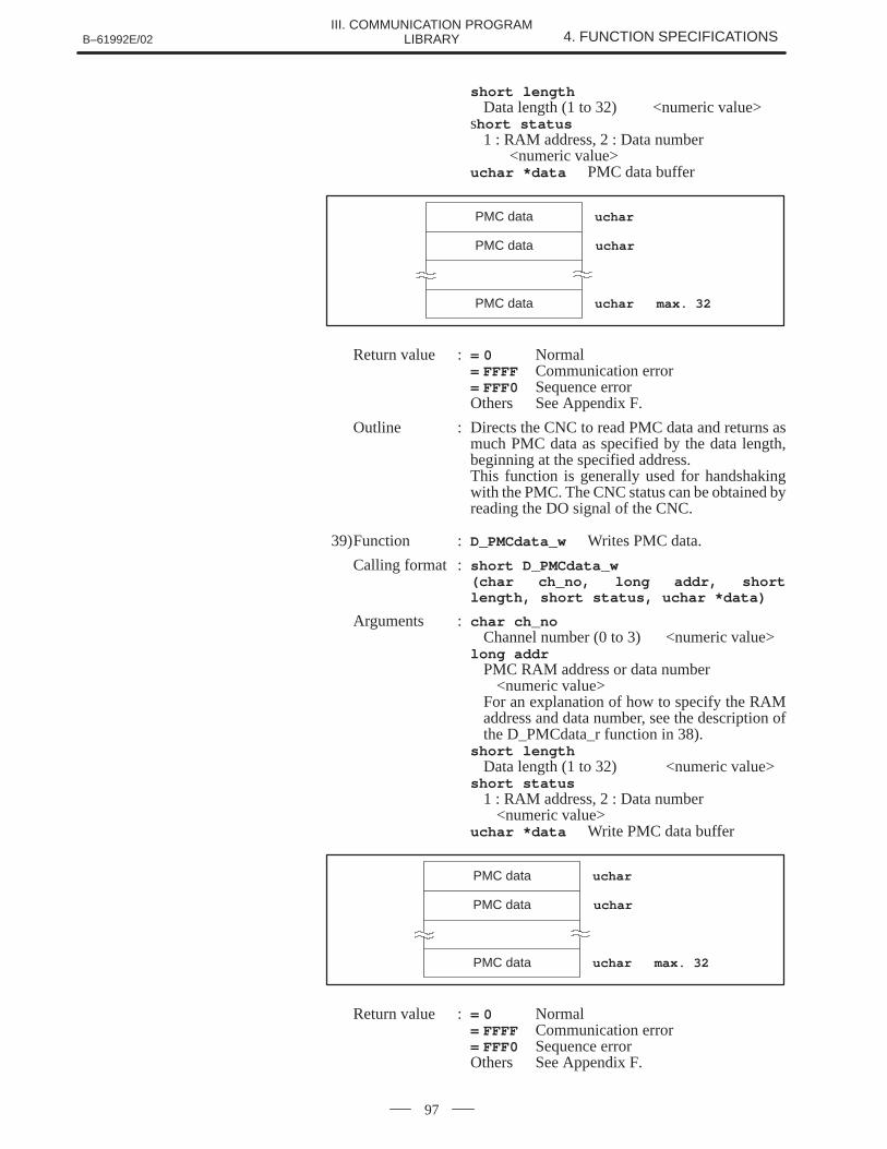
B–61992E/02 4. FUNCTION SPECIFICATIONSIII. COMMUNICATION PROGRAM
LIBRARY
97
short lengthData length (1 to 32) <numeric value>
short status1 : RAM address, 2 : Data number
<numeric value>uchar *data PMC data buffer
PMC data
PMC data
PMC data
uchar
uchar
uchar max. 32
Return value := 0 Normal= FFFF Communication error= FFF0 Sequence errorOthers See Appendix F.
Outline : Directs the CNC to read PMC data and returns asmuch PMC data as specified by the data length,beginning at the specified address.This function is generally used for handshakingwith the PMC. The CNC status can be obtained byreading the DO signal of the CNC.
39)Function : D_PMCdata_w Writes PMC data.
Calling format : short D_PMCdata_w (char ch_no, long addr, shortlength, short status, uchar *data)
Arguments : char ch_noChannel number (0 to 3) <numeric value>
long addrPMC RAM address or data number
<numeric value>For an explanation of how to specify the RAMaddress and data number, see the description ofthe D_PMCdata_r function in 38).
short lengthData length (1 to 32) <numeric value>
short status1 : RAM address, 2 : Data number
<numeric value>uchar *data Write PMC data buffer
PMC data
PMC data
PMC data
uchar
uchar
uchar max. 32
Return value := 0 Normal= FFFF Communication error= FFF0 Sequence errorOthers See Appendix F.
4. FUNCTION SPECIFICATIONS B–61992E/02III. COMMUNICATION PROGRAM
LIBRARY
98
Outline : Writes as much PMC data as specified by the datalength beginning at the specified address to theCNC.This function is generally used to give directionsto the PMC. This function permits handshakingwith the PMC in combination with the PMC dataread function.
40)Function : D_select Searches for a program number.Calling format : short D_select
(char ch_no, char *prg_no)
Arguments : char ch_noChannel number (0 to 3) <numeric value>
char *prg_noProgram number searched for
<character string>(o0000 to o9999)
Return value := 0 Normal= FFFF Communication error= FFF0 Sequence errorOthers See Appendix F.
Outline : Directs the CNC to search for a program number.In the tape mode, this function specifies theprogram number for performing a DNC operation.
* Release background edit mode and simultaneous edit mode (Series15 only) in advance.
* With the Series 15, the sequence terminates normally in any mode,but the function is made effective only in edit mode and memorymode.
41)Function : D_start Cycle startCalling format : short D_start
(char ch_no, char *prg_no)
Arguments : char ch_noChannel number (0 to 3) <numeric value>
char *prg_noProgram number to be started
<character string>(o0000 to o9999)If o0000 or a null code is entered, the programalready selected is started.
Return value := 0 Normal= FFFF Communication error= FFF0 Sequence errorOthers See Appendix F.
Outline : Specifies a program number for the CNC and startsthe program. If the program number is omitted, theCNC starts the executable program specified in theprogram number search function.If a complex condition check is required at cyclestart, avoid starting a program using this function.Use the PMC data write function instead.
B–61992E/02 4. FUNCTION SPECIFICATIONSIII. COMMUNICATION PROGRAM
LIBRARY
99
42)Function : D_reset ResetCalling format : short D_reset (char ch_no)
Arguments : char ch_noChannel number (0 to 3) <numeric value>
Return value := 0 Normal= FFFF Communication error= FFF0 Sequence errorOthers See Appendix F.
Outline : Directs the CNC to reset the system.
43)Function : D_systemID Reads system ID.Calling format : short D_system ID (char ch_no, uchar
*name, uchar *revision)
Arguments : char ch_noChannel number (0 to 3) <numeric value>
uchar *nameCNC model name <character string>(A maximum of 32 characters. Terminate the model name with a null code.)
uchar *revision Version <character string>(A maximum of eight characters. Terminate theversion with a null code.)
Return value := 0 Normal= FFFF Communication error= FFF0 Sequence errorOthers See Appendix F.
Outline : Directs the CNC to read the system ID. Returns theCNC model name and DNC2 software version.This function indicates the type of CNCconnected.
44)Function : D_initial Initializes communication port.Calling format : short D_initial (char ch_no)
Arguments : char ch_noChannel number (0 to 3) <numeric value>
(sys_table)Initialization parameter
Return value := 0 Normal= FFFF Initialization error= FFFE Parameter error
Outline : Initializes the specified communication port.
5. EXAMPLE OF USING 5. THE COMMUNICATION 5. PROGRAM B–61992E/02
III. COMMUNICATION PROGRAMLIBRARY
100
5 EXAMPLE OF USING THE COMMUNICATION PROGRAM
This section describes a simple example in which the functions in thecommunication program library are used, using list 5–1.
(1) Include the required files (5 and 6).� Enclose the include files required in the standard library of the
compiler in < > and include files of this library in double quotationmarks.
(2) Initialize the communication port (14 to 20).� Communication parameters can be reset to values different from
the initial values as shown in lines 14 and 15. (For initial values andreset values, see Appendix B.1.)
� Call the initialization library and store the result in ans. (Line 16)� When the result of initialization is not normal, output a message
(line 18) and terminate the program. (Line 19)
(3) Download the NC program (22 to 34).� Call the download library and store the result in ans. (Line 22)
Download the program with port number 0, download file name“pr_file.dat”, and program number 0001.
� Display a message according to the result. (Lines 23 to 34)
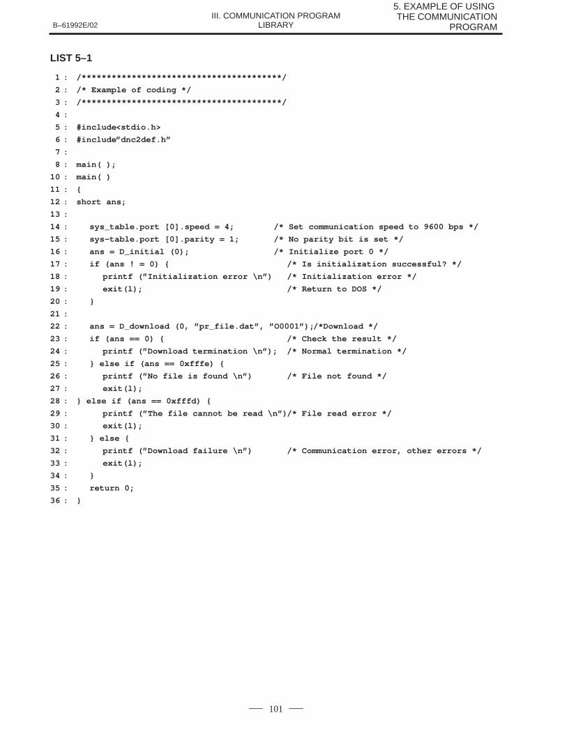
B–61992E/02
5. EXAMPLE OF USING THE COMMUNICATION
PROGRAMIII. COMMUNICATION PROGRAM
LIBRARY
101
LIST 5–1
1 : /****************************************/
2 : /* Example of coding */
3 : /****************************************/
4 :
5 : #include<stdio.h>
6 : #include”dnc2def.h”
7 :
8 : main( );
10 : main( )
11 : {
12 : short ans;
13 :
14 : sys_table.port [0].speed = 4; /* Set communication speed to 9600 bps */
15 : sys–table.port [0].parity = 1; /* No parity bit is set */
16 : ans = D_initial (0); /* Initialize port 0 */
17 : if (ans ! = 0) { /* Is initialization successful? */
18 : printf (”Initialization error \n”) /* Initialization error */
19 : exit(l); /* Return to DOS */
20 : }
21 :
22 : ans = D_download (0, ”pr_file.dat”, ”O0001”);/*Download */
23 : if (ans == 0) { /* Check the result */
24 : printf (”Download termination \n”); /* Normal termination */
25 : } else if (ans == 0xfffe) {
26 : printf (”No file is found \n”) /* File not found */
27 : exit(l);
28 : } else if (ans == 0xfffd) {
29 : printf (”The file cannot be read \n”)/* File read error */
30 : exit(l);
31 : } else {
32 : printf (”Download failure \n”) /* Communication error, other errors */
33 : exit(l);
34 : }
35 : return 0;
36 : }

6. ERROR CODES B–61992E/02III. COMMUNICATION PROGRAM
LIBRARY
102
6 ERROR CODES
B–61992E/02 6. ERROR CODESIII. COMMUNICATION PROGRAM
LIBRARY
103
The return values 0FFFFh to 0FFCFh (absolute values of 1 to 49) outputfrom functions in this library indicate errors detected within the library.The return values of 0FFCEh or less (absolute values of 50 or greater)indicate errors output when a negative response is sent from the CNC.For details of the error codes of this library, see Appendix J.
If values returned from functions indicate communication error(0FFFFh), the details of the cause are stored in the variablednc_link_error. Refer to it an necessary.The following values are returned to short dnc link error from thefunctions:
short dnc_link_error
1 : Time–out2 : Retry over3 : Busy (during text transmission, a response to ENQ was NAK)4 : Protocol error (when receiving text, other data was received
when waiting for ENQ)5 : Warning (when receiving text, a time–out occurred when
waiting for EOT. However, text is normally received.)11 : Line disconnected12 : Overrun error13 : Framing error14 : Parity error21 : ISO code parity error
The communication error having code 1 occurs when thereceive–disabled state occurs for each retry within the time–out period setfor receiving or sending each character. As soon as this error is detected,processing is discontinued.
This does not apply while waiting for a down–load request(D_download_wait ) or while waiting for a command from the CNC. Inthese cases the system keeps waiting for a command even though atime–out occurs.
The communication error having code 2 occurs when a retry is made inthe data link layer level for any cause other than time–out and the definednumber of retries is repeated. As soon as this error is detected, processingis stopped.
The communication errors having codes 3 to 9 are data link layer protocolerrors. As soon as these errors occur, processing is stopped.
The communication errors having codes 10 or more are communicationline errors. As soon as these errors are detected, processing is stopped.
6.1VALUES RETURNEDBY FUNCTIONS
6.2COMMUNICATIONERRORINFORMATION
7. ERROR LOG INFORMATION B–61992E/02III. COMMUNICATION PROGRAM
LIBRARY
104
7 ERROR LOG INFORMATION
When an error occurs in this library, the error, the time it occurred, andother information can be saved in a file. A function called the loggingfunction, is provided for saving this information.
There are the following four types of logs depending on the cause of theerror:sequence error log, protocol error log, phase trace log, andcommunication error log.
To use the logging function, set the appropriate log ON/OFF switch ofsystem parameter to 1 : ON.
This logging function is used to check programs. Normally, do not use it.Since phase trace logs are taken at all times, the file input–output timeincreases, affecting the time–out period. Therefore, use the loggingfunction carefully.
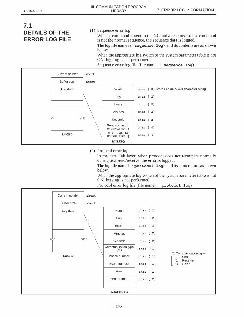
B–61992E/02 7. ERROR LOG INFORMATIONIII. COMMUNICATION PROGRAM
LIBRARY
105
(1) Sequence error logWhen a command is sent to the NC and a response to the commandis not the normal sequence, the sequence data is logged.The log file name is <sequence.log > and its contents are as shownbelow.When the appropriate log switch of the system parameter table is notON, logging is not performed.Sequence error log file (file name : sequence.log )
shortCurrent pointer
shortBuffer size
Log data Month
Day
Hours
Minutes
Seconds
Send commandcharacter stringError responsecharacter string
LOGSEQ
LOGHD
char [ 2] Stored as an ASCII character string.
char [ 2]
char [ 2]
char [ 2]
char [ 2]
char [ 4]
char [ 4]
(2) Protocol error logIn the data link layer, when protocol does not terminate normallyduring text send/receive, the error is logged.The log file name is <protocol.log > and its contents are as shownbelow.When the appropriate log switch of the system parameter table is notON, logging is not performed.Protocol error log file (file name : protocol.log )
shortCurrent pointer
shortBuffer size
Log data Month
Day
Hours
Minutes
Seconds
Communication type(*1)
Phase number
LOGPROTC
LOGHD
char [ 2]
char [ 2]
char [ 2]
char [ 2]
char [ 2]
char [ 1]
char [ 1]
Event number
Free
char [ 1]
char [ 1]
char [ 2]Error number
*1 Communication type’1’: Send’2’: Receive’3’: Clear
7.1DETAILS OF THEERROR LOG FILE
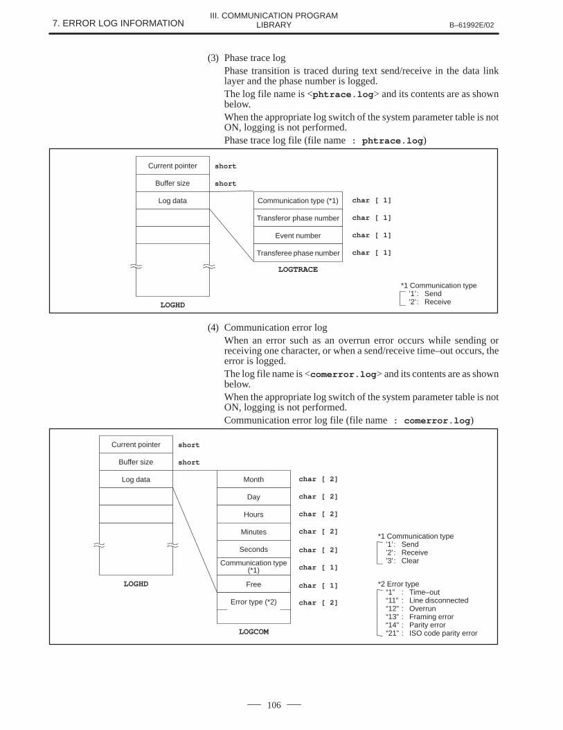
7. ERROR LOG INFORMATION B–61992E/02III. COMMUNICATION PROGRAM
LIBRARY
106
(3) Phase trace logPhase transition is traced during text send/receive in the data linklayer and the phase number is logged.The log file name is <phtrace.log > and its contents are as shownbelow.When the appropriate log switch of the system parameter table is notON, logging is not performed.Phase trace log file (file name : phtrace.log )
shortCurrent pointer
shortBuffer size
Log data Communication type (*1)
Transferor phase number
Event number
Transferee phase number
LOGTRACE
LOGHD
char [ 1]
char [ 1]
char [ 1]
char [ 1]
*1 Communication type’1’: Send’2’: Receive
(4) Communication error logWhen an error such as an overrun error occurs while sending orreceiving one character, or when a send/receive time–out occurs, theerror is logged.The log file name is <comerror.log > and its contents are as shownbelow.When the appropriate log switch of the system parameter table is notON, logging is not performed.Communication error log file (file name : comerror.log )
shortCurrent pointer
shortBuffer size
Log data Month
Day
Hours
Minutes
Seconds
Communication type(*1)
LOGCOM
LOGHD
char [ 2]
char [ 2]
char [ 2]
char [ 2]
char [ 2]
char [ 1]
Free char [ 1]
char [ 2]Error type (*2)
*1 Communication type’1’: Send’2’: Receive’3’: Clear
*2 Error type“1” : Time–out“11” : Line disconnected“12” : Overrun“13” : Framing error“14” : Parity error“21” : ISO code parity error
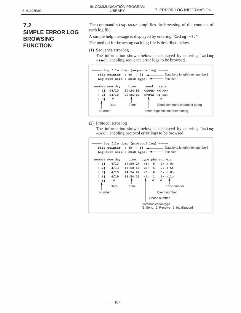
B–61992E/02 7. ERROR LOG INFORMATIONIII. COMMUNICATION PROGRAM
LIBRARY
107
The command <log.exe > simplifies the browsing of the contents ofeach log file.
A simple help message is displayed by entering “C>log –?. ”
The method for browsing each log file is described below.
(1) Sequence error logThe information shown below is displayed by entering “C>log–seq ”, enabling sequence error logs to be browsed.
===== Log file dump [sequence.log] =====
File pointer : 40 [ 3] Data byte length [next number] Log buff size : 2048(bype) File size
number mon day time send recv
[ 1] 04/10 20:24:53 <PRPM> <M NR>
[ 2] 04/10 20:26:02 <PTPA> <T BD>
[ 3]
Number
Date Time
Error response character string
Send command character string
(2) Protocol error logThe information shown below is displayed by entering “C>log–pro ”, enabling protocol error logs to be browsed.
===== Log file dump [protocol.log] =====
File pointer : 68 [ 5] Data byte length [next number] Log buff size : 2048(bype) File size
number mon day time type pha evt err
[ 1] 4/13 17:50:24 <2: 5 2> < 5>
[ 2] 4/13 17:50:48 <2: 5 2> < 5>
[ 3] 4/19 14:54:24 <3: 0 0> < 0>
[ 4] 4/19 14:54:31 <1: 1 1> <11>
[ 5]
Number
Date Time
Event number
Error number
Phase number
Communication type [1: Send, 2: Receive, 3: Intialization]
7.2SIMPLE ERROR LOGBROWSINGFUNCTION
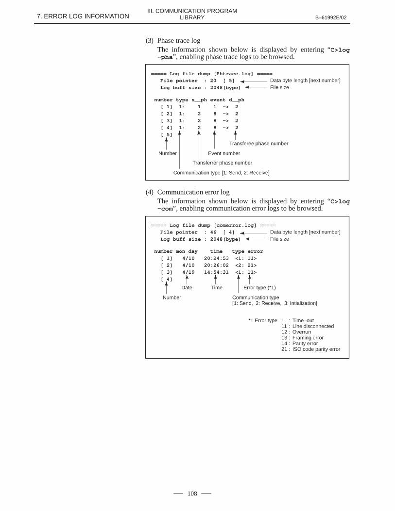
7. ERROR LOG INFORMATION B–61992E/02III. COMMUNICATION PROGRAM
LIBRARY
108
(3) Phase trace logThe information shown below is displayed by entering “C>log–pha ”, enabling phase trace logs to be browsed.
===== Log file dump [Phtrace.log] =====
File pointer : 20 [ 5] Data byte length [next number] Log buff size : 2048(bype) File size
number type s__ph event d__ph
[ 1] 1: 1 1 –> 2
[ 2] 1: 2 8 –> 2
[ 3] 1: 2 8 –> 2
[ 4] 1: 2 8 –> 2
[ 5]
Number Event number
Transferee phase number
Transferrer phase number
Communication type [1: Send, 2: Receive]
(4) Communication error logThe information shown below is displayed by entering “C>log–com”, enabling communication error logs to be browsed.
===== Log file dump [comerror.log] =====
File pointer : 46 [ 4] Data byte length [next number] Log buff size : 2048(bype) File size
number mon day time type error
[ 1] 4/10 20:24:53 <1: 11>
[ 2] 4/10 20:26:02 <2: 21>
[ 3] 4/19 14:54:31 <1: 11>
[ 4]
Number
Date Time
Communication type [1: Send, 2: Receive, 3: Intialization]
Error type (*1)
*1 Error type 1 : Time–out11 : Line disconnected12 : Overrun13 : Framing error14 : Parity error21 : ISO code parity error

APPENDIX

B–61992E/02 A. CONNECTOR SPECIFICATIONSAPPENDIX
111
A CONNECTOR SPECIFICATIONS
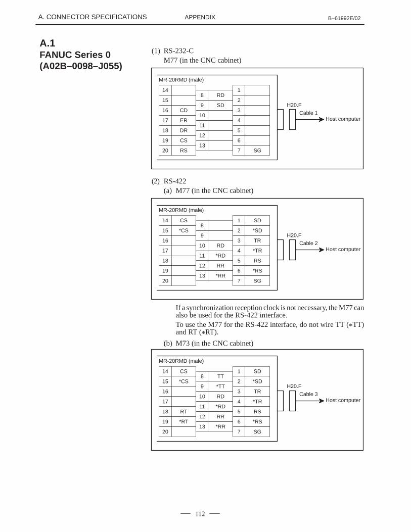
A. CONNECTOR SPECIFICATIONS B–61992E/02APPENDIX
112
(1) RS-232-CM77 (in the CNC cabinet)
Cable 1
H20.F
MR-20RMD (male)
Host computer
14
15
16 CD
17 ER
18 DR
19 CS
20 RS
8 RD
9 SD
10
11
12
13
1
2
3
4
5
6
7 SG
(2) RS-422(a) M77 (in the CNC cabinet)
Cable 2
H20.F
MR-20RMD (male)
Host computer
14 CS
15 *CS
16
17
18
19
20
8
9
10 RD
11 *RD
12 RR
13 *RR
1 SD
2 *SD
3 TR
4 *TR
5 RS
6 *RS
7 SG
If a synchronization reception clock is not necessary, the M77 canalso be used for the RS-422 interface.To use the M77 for the RS-422 interface, do not wire TT (*TT)and RT (*RT).
(b) M73 (in the CNC cabinet)
Cable 3
H20.F
MR-20RMD (male)
Host computer
14 CS
15 *CS
16
17
18 RT
19 *RT
20
8 TT
9 *TT
10 RD
11 *RD
12 RR
13 *RR
1 SD
2 *SD
3 TR
4 *TR
5 RS
6 *RS
7 SG
A.1FANUC Series 0(A02B–0098–J055)
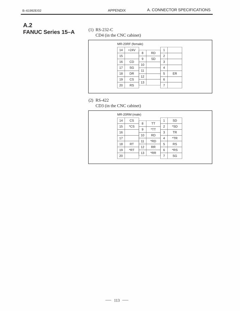
B–61992E/02 A. CONNECTOR SPECIFICATIONSAPPENDIX
113
(1) RS-232-CCD4 (in the CNC cabinet)
MR-20RF (female)
14 +24V
15
16 CD
17 SG
18 DR
19 CS
20 RS
8 RD
9 SD
10
11
12
13
1
2
3
4
5 ER
6
7
(2) RS-422CD3 (in the CNC cabinet)
MR-20RM (male)
14 CS
15 *CS
16
17
18 RT
19 *RT
20
8 TT
9 *TT
10 RD
11 *RD
12 RR
13 *RR
1 SD
2 *SD
3 TR
4 *TR
5 RS
6 *RS
7 SG
A.2FANUC Series 15–A
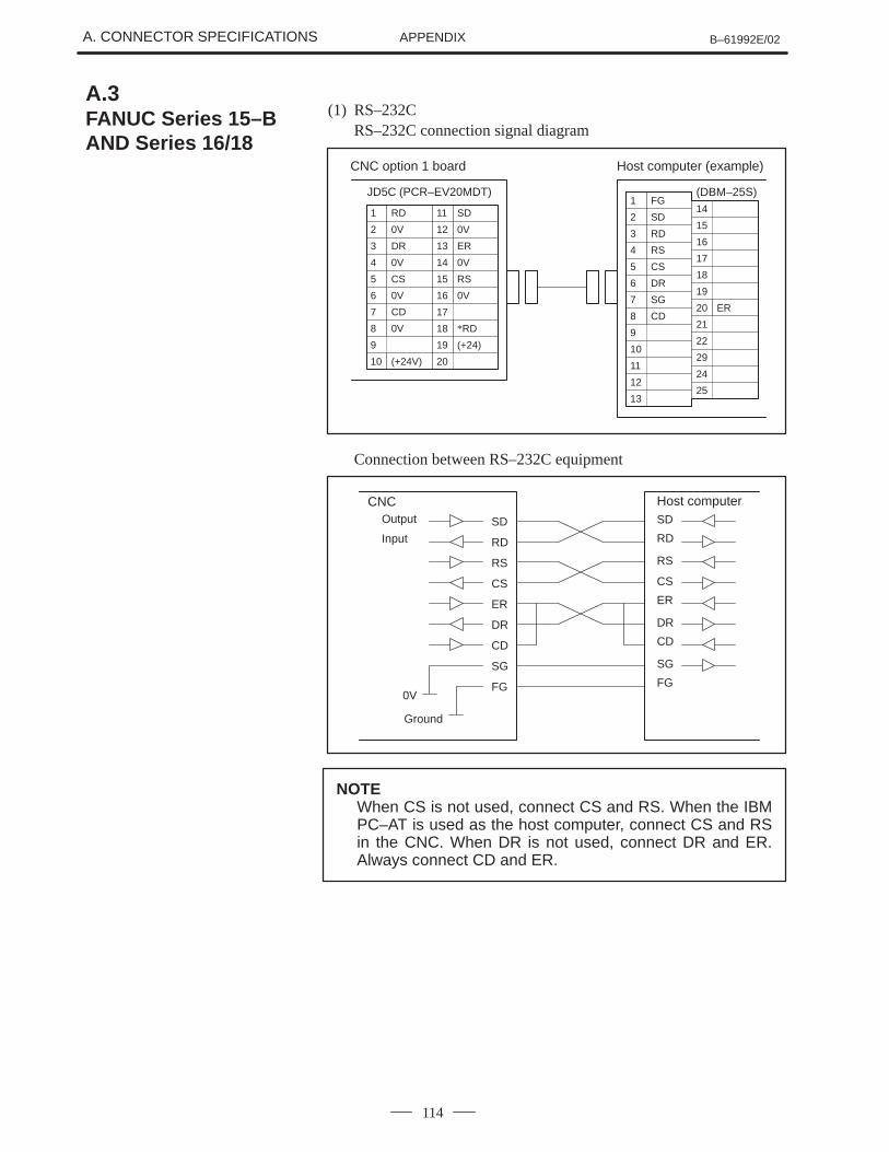
A. CONNECTOR SPECIFICATIONS B–61992E/02APPENDIX
114
(1) RS–232CRS–232C connection signal diagram
CNC option 1 board
JD5C (PCR–EV20MDT)1 FG
2 SD
3 RD
4 RS
5 CS
6 DR
7 SG
8 CD
9
10
11
12
13
14
15
16
17
18
19
Host computer (example)
20 ER
21
22
29
24
25
4 0V
5 CS
6 0V
7 CD
11 SD
8 0V
9
10 (+24V)
1 RD
12 0V
13 ER
14 0V
15 RS
2 0V
16 0V
3 DR
17
18 *RD
19 (+24)
20
(DBM–25S)
Connection between RS–232C equipment
SD
RD
SD
RD
RS
CS
RS
ER
DR
SG
FG
CNC Host computer
CS
ER
DR
SG
FG
CD CD
0V
Output
Input
Ground
NOTEWhen CS is not used, connect CS and RS. When the IBMPC–AT is used as the host computer, connect CS and RSin the CNC. When DR is not used, connect DR and ER.Always connect CD and ER.
A.3FANUC Series 15–BAND Series 16/18
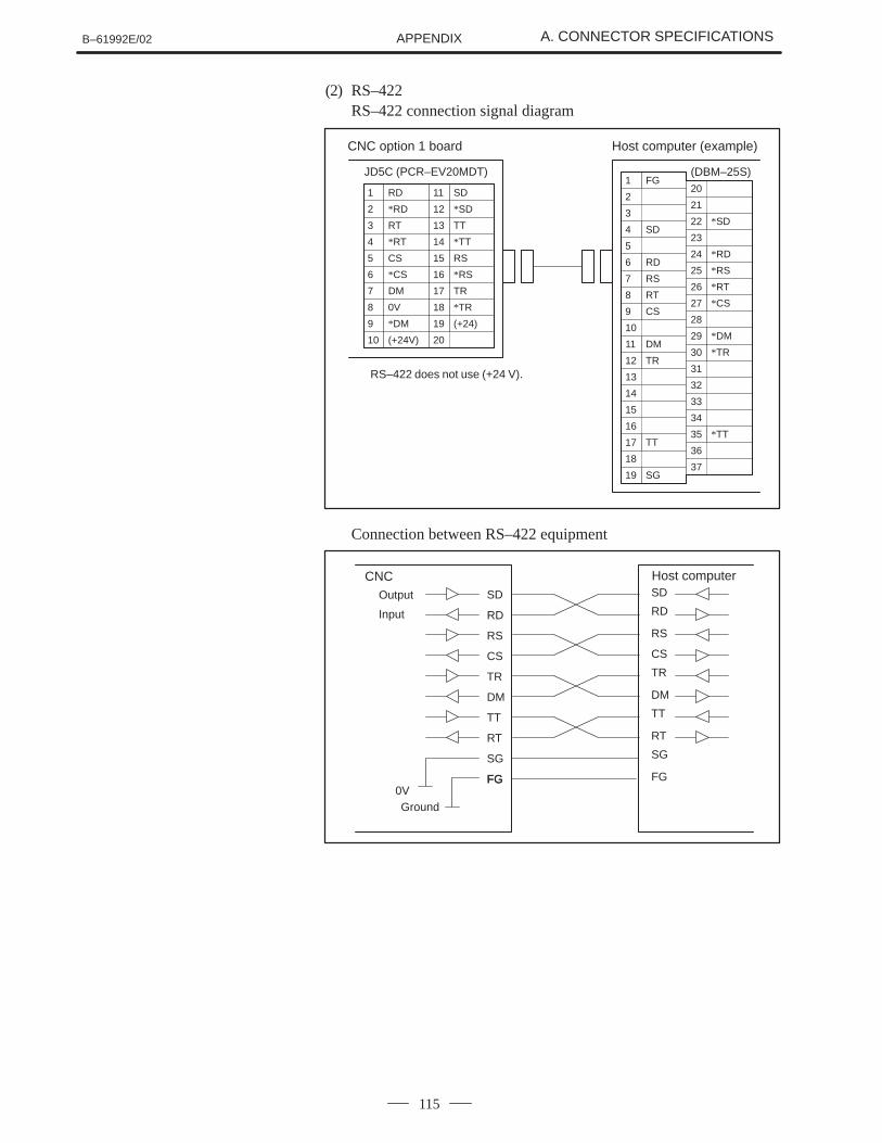
B–61992E/02 A. CONNECTOR SPECIFICATIONSAPPENDIX
115
(2) RS–422RS–422 connection signal diagram
CNC option 1 board
JD5C (PCR–EV20MDT)
Host computer (example)
4 *RT
5 CS
6 *CS
7 DM
11 SD
8 0V
9 *DM
10 (+24V)
1 RD
12 *SD
13 TT
14 *TT
15 RS
2 *RD
16 *RS
3 RT
17 TR
18 *TR
19 (+24)
20
(DBM–25S)1 FG
2
3
4 SD
5
6 RD
7 RS
8 RT
9 CS
10
11 DM
12 TR
13
14
15
16
17 TT
18
19 SG
20
21
22 *SD
23
24 *RD
25 *RS
26 *RT
27 *CS
28
29 *DM
30 *TR
31
32
33
34
35 *TT
36
37
RS–422 does not use (+24 V).
Connection between RS–422 equipment
SD
RD
SD
RD
RS
CS
RS
TR
DM
RT
CS
TR
DM
RT
SG
FG
TT TT
SG
FGFG0V
CNC Host computerOutput
Input
Ground
B. PARAMETERS B–61992E/02APPENDIX
116
B PARAMETERS
The following parameters are sent to the DNC2 system onlywhen the CNC is turned on. After changing any of theparameters, turn off and on again the power switch of the CNC.
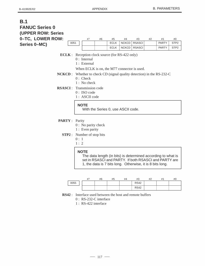
B–61992E/02 B. PARAMETERSAPPENDIX
117
#7
0051#6 #5
ECLK#4
NCKCD#3
RSASCI#2 #1
PARTY#0
STP2
ECLK NCKCD RSASCI PARTY STP2
ECLK : Reception clock source (for RS-422 only)0 : Internal1 : External
When ECLK is on, the M77 connector is used.
NCKCD : Whether to check CD (signal quality detection) in the RS-232-C0 : Check1 : No check
RSASCI : Transmission code0 : ISO code1 : ASCII code
NOTEWith the Series 0, use ASCII code.
PARTY : Parity0 : No parity check1 : Even parity
STP2 : Number of stop bits0 : 11 : 2
NOTEThe data length (in bits) is determined according to what isset in RSASCI and PARTY. If both RSASCI and PARTY are1, the data is 7 bits long. Otherwise, it is 8 bits long.
#7
0055#6 #5 #4 #3
RS42#2 #1 #0
RS42
RS42 : Interface used between the host and remote buffers0 : RS-232-C interface1 : RS-422 interface
B.1FANUC Series 0 (UPPER ROW: Series0–TC, LOWER ROW:Series 0–MC)
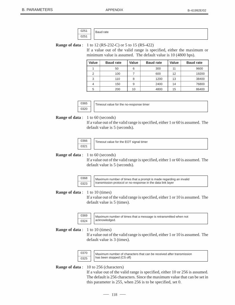
B. PARAMETERS B–61992E/02APPENDIX
118
0251 Baud rate0251
Range of data : 1 to 12 (RS-232-C) or 5 to 15 (RS-422)If a value out of the valid range is specified, either the maximum orminimum value is assumed. The default value is 10 (4800 bps).
Value Baud rate Value Baud rate Value Baud rate
1 50 6 300 11 9600
2 100 7 600 12 19200
3 110 8 1200 13 38400
4 150 9 2400 14 76800
5 200 10 4800 15 86400
0365 Timeout value for the no-response timer0320
Range of data : 1 to 60 (seconds)If a value out of the valid range is specified, either 1 or 60 is assumed. Thedefault value is 5 (seconds).
0366 Timeout value for the EOT signal timer0321
Range of data : 1 to 60 (seconds)If a value out of the valid range is specified, either 1 or 60 is assumed. Thedefault value is 5 (seconds).
0368 Maximum number of times that a prompt is made regarding an invalidtransmission protocol or no-response in the data link layer0323
Range of data : 1 to 10 (times)If a value out of the valid range is specified, either 1 or 10 is assumed. Thedefault value is 5 (times).
0369 Maximum number of times that a message is retransmitted when notacknowledged.0324
Range of data : 1 to 10 (times)If a value out of the valid range is specified, either 1 or 10 is assumed. Thedefault value is 3 (times).
0370 Maximum number of characters that can be received after transmissionhas been stopped (CS off)0325
Range of data : 10 to 256 (characters)If a value out of the valid range is specified, either 10 or 256 is assumed.The default is 256 characters. Since the maximum value that can be set inthis parameter is 255, when 256 is to be specified, set 0.
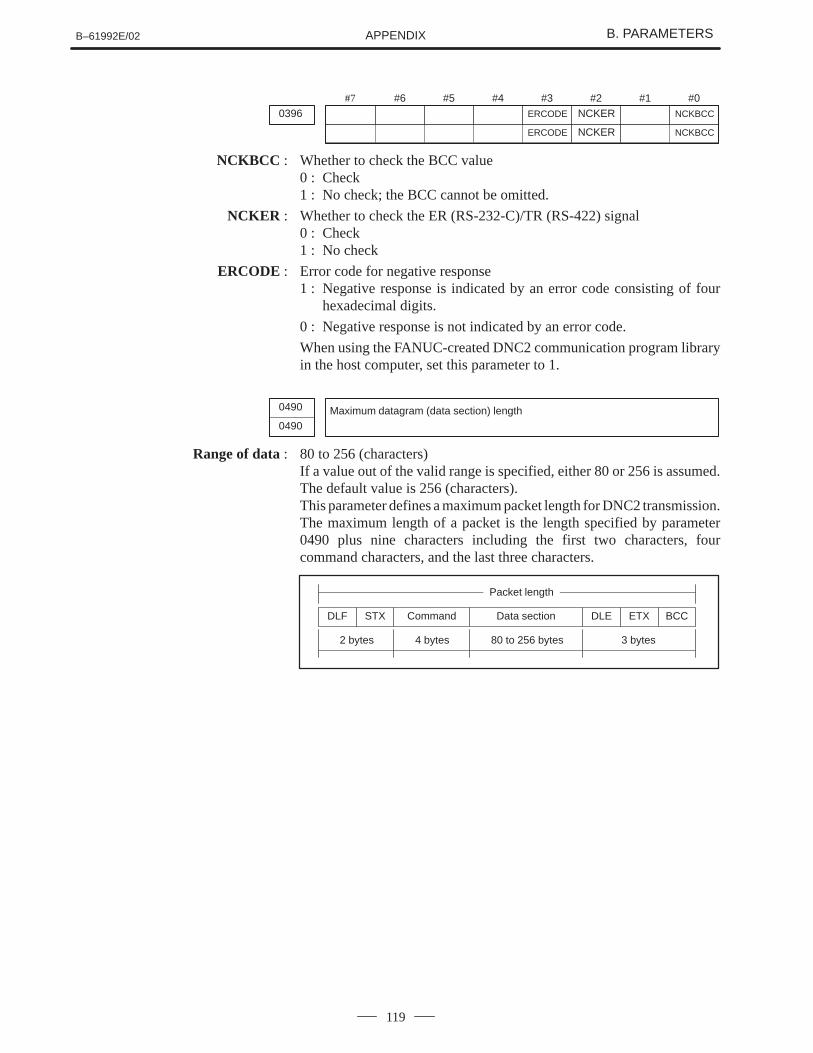
B–61992E/02 B. PARAMETERSAPPENDIX
119
#7
0396#6 #5 #4 #3
ERCODE
#2NCKER
#1 #0NCKBCC
ERCODE NCKER NCKBCC
NCKBCC : Whether to check the BCC value0 : Check1 : No check; the BCC cannot be omitted.
NCKER : Whether to check the ER (RS-232-C)/TR (RS-422) signal0 : Check1 : No check
ERCODE : Error code for negative response1 : Negative response is indicated by an error code consisting of four
hexadecimal digits.
0 : Negative response is not indicated by an error code.
When using the FANUC-created DNC2 communication program libraryin the host computer, set this parameter to 1.
0490 Maximum datagram (data section) length0490
Range of data : 80 to 256 (characters)If a value out of the valid range is specified, either 80 or 256 is assumed.The default value is 256 (characters).This parameter defines a maximum packet length for DNC2 transmission.The maximum length of a packet is the length specified by parameter0490 plus nine characters including the first two characters, fourcommand characters, and the last three characters.
DLF STX DLE ETX BCCCommand Data section
2 bytes 4 bytes 80 to 256 bytes 3 bytes
Packet length
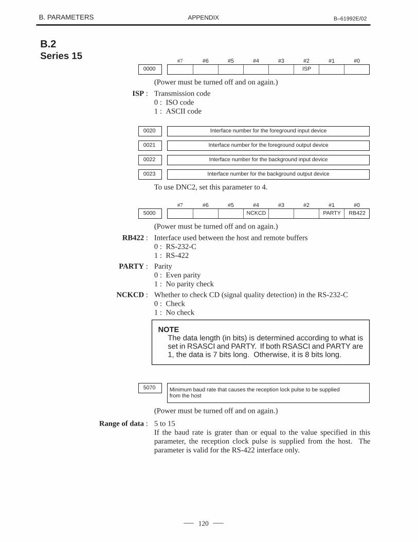
B. PARAMETERS B–61992E/02APPENDIX
120
#7
0000#6 #5 #4 #3 #2
ISP#1 #0
(Power must be turned off and on again.)
ISP : Transmission code0 : ISO code1 : ASCII code
0020 Interface number for the foreground input device
0021 Interface number for the foreground output device
0022 Interface number for the background input device
0023 Interface number for the background output device
To use DNC2, set this parameter to 4.
#7
5000#6 #5 #4
NCKCD#3 #2 #1
PARTY#0
RB422
(Power must be turned off and on again.)
RB422 : Interface used between the host and remote buffers0 : RS-232-C1 : RS-422
PARTY : Parity0 : Even parity1 : No parity check
NCKCD : Whether to check CD (signal quality detection) in the RS-232-C0 : Check1 : No check
NOTEThe data length (in bits) is determined according to what isset in RSASCI and PARTY. If both RSASCI and PARTY are1, the data is 7 bits long. Otherwise, it is 8 bits long.
5070 Minimum baud rate that causes the reception lock pulse to be suppliedfrom the host
(Power must be turned off and on again.)
Range of data : 5 to 15If the baud rate is grater than or equal to the value specified in thisparameter, the reception clock pulse is supplied from the host. Theparameter is valid for the RS-422 interface only.
B.2Series 15
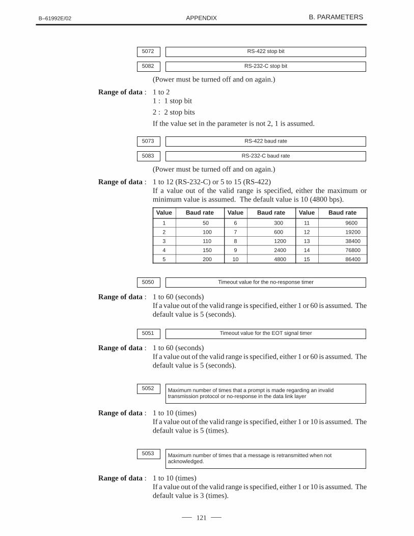
B–61992E/02 B. PARAMETERSAPPENDIX
121
5072 RS-422 stop bit
5082 RS-232-C stop bit
(Power must be turned off and on again.)
Range of data : 1 to 21 : 1 stop bit
2 : 2 stop bits
If the value set in the parameter is not 2, 1 is assumed.
5073 RS-422 baud rate
5083 RS-232-C baud rate
(Power must be turned off and on again.)
Range of data : 1 to 12 (RS-232-C) or 5 to 15 (RS-422)If a value out of the valid range is specified, either the maximum orminimum value is assumed. The default value is 10 (4800 bps).
Value Baud rate Value Baud rate Value Baud rate
1 50 6 300 11 9600
2 100 7 600 12 19200
3 110 8 1200 13 38400
4 150 9 2400 14 76800
5 200 10 4800 15 86400
5050 Timeout value for the no-response timer
Range of data : 1 to 60 (seconds)If a value out of the valid range is specified, either 1 or 60 is assumed. Thedefault value is 5 (seconds).
5051 Timeout value for the EOT signal timer
Range of data : 1 to 60 (seconds)If a value out of the valid range is specified, either 1 or 60 is assumed. Thedefault value is 5 (seconds).
5052 Maximum number of times that a prompt is made regarding an invalidtransmission protocol or no-response in the data link layer
Range of data : 1 to 10 (times)If a value out of the valid range is specified, either 1 or 10 is assumed. Thedefault value is 5 (times).
5053 Maximum number of times that a message is retransmitted when notacknowledged.
Range of data : 1 to 10 (times)If a value out of the valid range is specified, either 1 or 10 is assumed. Thedefault value is 3 (times).
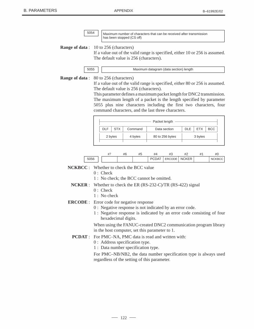
B. PARAMETERS B–61992E/02APPENDIX
122
5054 Maximum number of characters that can be received after transmissionhas been stopped (CS off)
Range of data : 10 to 256 (characters)If a value out of the valid range is specified, either 10 or 256 is assumed.The default value is 256 (characters).
5055 Maximum datagram (data section) length
Range of data : 80 to 256 (characters)If a value out of the valid range is specified, either 80 or 256 is assumed.The default value is 256 (characters).This parameter defines a maximum packet length for DNC2 transmission.The maximum length of a packet is the length specified by parameter5055 plus nine characters including the first two characters, fourcommand characters, and the last three characters.
DLF STX DLE ETX BCCCommand Data section
2 bytes 4 bytes 80 to 256 bytes 3 bytes
Packet length
#7
5056#6 #5 #4
PCDAT#3
ERCODE
#2NCKER
#1 #0NCKBCC
NCKBCC : Whether to check the BCC value0 : Check1 : No check; the BCC cannot be omitted.
NCKER : Whether to check the ER (RS-232-C)/TR (RS-422) signal0 : Check1 : No check
ERCODE : Error code for negative response0 : Negative response is not indicated by an error code.1 : Negative response is indicated by an error code consisting of four
hexadecimal digits.
When using the FANUC-created DNC2 communication program libraryin the host computer, set this parameter to 1.
PCDAT : For PMC–NA, PMC data is read and written with:0 : Address specification type.1 : Data number specification type.
For PMC–NB/NB2, the data number specification type is always usedregardless of the setting of this parameter.
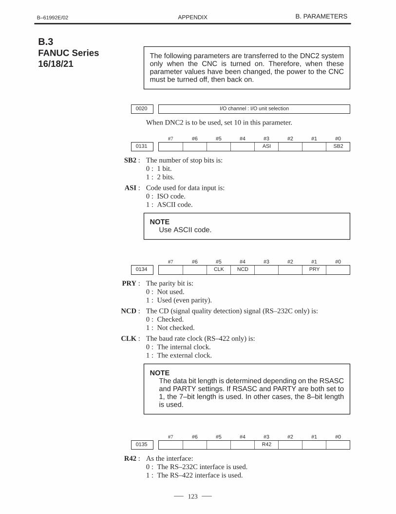
B–61992E/02 B. PARAMETERSAPPENDIX
123
The following parameters are transferred to the DNC2 systemonly when the CNC is turned on. Therefore, when theseparameter values have been changed, the power to the CNCmust be turned off, then back on.
0020 I/O channel : I/O unit selection
When DNC2 is to be used, set 10 in this parameter.
#7
0131#6 #5 #4 #3
ASI#2 #1 #0
SB2
SB2 : The number of stop bits is:0 : 1 bit.1 : 2 bits.
ASI : Code used for data input is:0 : ISO code.1 : ASCII code.
NOTEUse ASCII code.
#7
0134#6 #5
CLK#4
NCD#3 #2 #1
PRY#0
PRY : The parity bit is:0 : Not used.1 : Used (even parity).
NCD : The CD (signal quality detection) signal (RS–232C only) is:0 : Checked.1 : Not checked.
CLK : The baud rate clock (RS–422 only) is:0 : The internal clock.1 : The external clock.
NOTEThe data bit length is determined depending on the RSASCand PARTY settings. If RSASC and PARTY are both set to1, the 7–bit length is used. In other cases, the 8–bit lengthis used.
#7
0135#6 #5 #4 #3
R42#2 #1 #0
R42 : As the interface:0 : The RS–232C interface is used.1 : The RS–422 interface is used.
B.3FANUC Series16/18/21
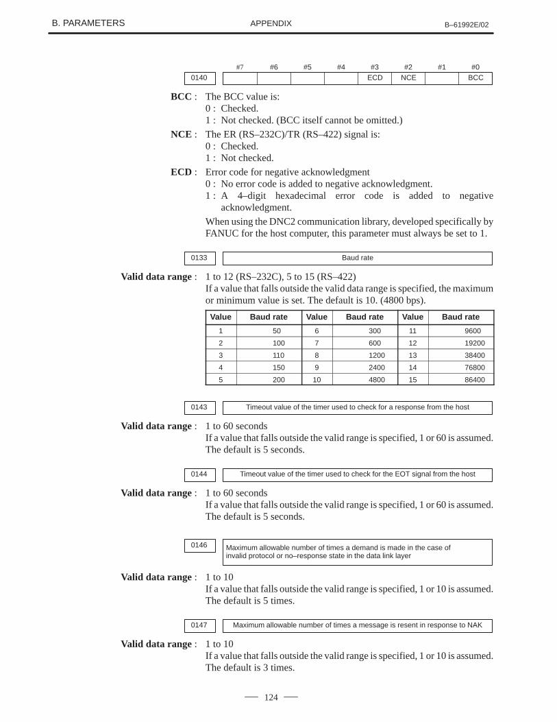
B. PARAMETERS B–61992E/02APPENDIX
124
#7
0140#6 #5 #4 #3
ECD#2
NCE#1 #0
BCC
BCC : The BCC value is:0 : Checked.1 : Not checked. (BCC itself cannot be omitted.)
NCE : The ER (RS–232C)/TR (RS–422) signal is:0 : Checked.1 : Not checked.
ECD : Error code for negative acknowledgment0 : No error code is added to negative acknowledgment.1 : A 4–digit hexadecimal error code is added to negative
acknowledgment.
When using the DNC2 communication library, developed specifically byFANUC for the host computer, this parameter must always be set to 1.
0133 Baud rate
Valid data range : 1 to 12 (RS–232C), 5 to 15 (RS–422)If a value that falls outside the valid data range is specified, the maximumor minimum value is set. The default is 10. (4800 bps).
Value Baud rate Value Baud rate Value Baud rate
1 50 6 300 11 9600
2 100 7 600 12 19200
3 110 8 1200 13 38400
4 150 9 2400 14 76800
5 200 10 4800 15 86400
0143 Timeout value of the timer used to check for a response from the host
Valid data range : 1 to 60 secondsIf a value that falls outside the valid range is specified, 1 or 60 is assumed.The default is 5 seconds.
0144 Timeout value of the timer used to check for the EOT signal from the host
Valid data range : 1 to 60 secondsIf a value that falls outside the valid range is specified, 1 or 60 is assumed.The default is 5 seconds.
0146 Maximum allowable number of times a demand is made in the case ofinvalid protocol or no–response state in the data link layer
Valid data range : 1 to 10If a value that falls outside the valid range is specified, 1 or 10 is assumed.The default is 5 times.
0147 Maximum allowable number of times a message is resent in response to NAK
Valid data range : 1 to 10If a value that falls outside the valid range is specified, 1 or 10 is assumed.The default is 3 times.
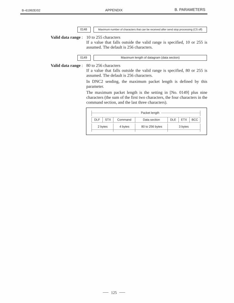
B–61992E/02 B. PARAMETERSAPPENDIX
125
0148 Maximum number of characters that can be received after send stop processing (CS off)
Valid data range : 10 to 255 charactersIf a value that falls outside the valid range is specified, 10 or 255 isassumed. The default is 256 characters.
0149 Maximum length of datagram (data section)
Valid data range : 80 to 256 charactersIf a value that falls outside the valid range is specified, 80 or 255 isassumed. The default is 256 characters.
In DNC2 sending, the maximum packet length is defined by thisparameter.
The maximum packet length is the setting in [No. 0149] plus ninecharacters (the sum of the first two characters, the four characters in thecommand section, and the last three characters).
DLF STX DLE ETX BCCCommand Data section
2 bytes 4 bytes 80 to 256 bytes 3 bytes
Packet length
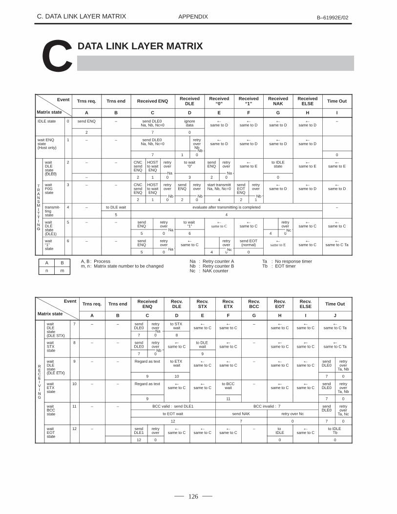
C. DATA LINK LAYER MATRIX B–61992E/02APPENDIX
126
C DATA LINK LAYER MATRIX
Event Trns req. Trns end Received ENQ ReceivedDLE
Received“0”
Received“1”
ReceivedNAK
ReceivedELSE Time Out
Matrix state A B C D E F G H I
IDLE state 0 send ENQ – send DLE0 Na, Nb, Nc=0
ignoredata
�same to D
�same to D
�same to D
�same to D
–
2 7 0
wait ENQstate (Host only)
1 – – send DLE0 Na, Nb, Nc=0
retryoverNb
�same to D
�same to D
�same to D
�same to D
7 1 0 0
wait DLEstate(DLE0)
2 – – CNCsendENQ
HOSTto waitENQ
retryover
to wait“0”
sendENQ
retryover
�same to E
to IDLEstate
�same to E
�same to E
(DLE0)– 2 1 0 3 2 0 0
TRA
wait F0Gstate
3 – – CNCsendENQ
HOSTto waitENQ
retryover
sendENQ
retryover
start transmittNa, Nb, Nc=0
sendEOTENQ
retryover
�same to D
�same to D
�same to D
ANS 2 1 0 2 0 4 2 1SMI transmit-
ting4 – to DLE wait evaluate after transmitting is completed –I
TT
tingstate 5 4
TING
wait DLEstate
5 – – sendENQ
retryover
to wait “1”
�same to C
�same to C
retryover
�same to C
�same to C
G state(DLE1) 5 0 6 4 0
wait “1”state
6 – – sendENQ
retryover
�same to C
retryover
send EOT(normal)
�same to E
�same to C
�same to C Ta
state5 0 4 0 0
A, B : Processm, n: Matrix state number to be changed
Na : Retry counter ANb : Retry counter BNc : NAK counter
Ta : No response timerTb : EOT timer
A B
n m
EventTrns req. Trns end Received
ENQRecv.DLE
Recv.STX
Recv.ETX
Recv.BCC
Recv.EOT
Recv.ELSE Time Out
Matrix state A B C D E F G H I J
wait DLEstate
7 – – sendDLE0
retryover
to STX wait
�same to C
�same to C
– �same to C
�same to C
�same to C Ta
state(DLE STX) 7 0 8
wait STXstate
8 – – sendDLE0
retryover
�same to C
to DLE wait
�same to C
– �same to C
�same to C
�same to C Ta
state7 0 9
RE
waitDLEstate(DLE ETX)
9 – – Regard as text to ETX wait
�same to C
�same to C
– �same to C
�same to C
sendDLE0
retryover
Ta, NbECE
(DLE ETX)9 10 7 0E
IVIN
waitETXstate
10 – – Regard as text �same to C
�same to C
to BCCwait
– �same to C
�same to C
sendDLE0
retryover
Ta, NbNG 9 11 7 0
wait BCC
11 – – BCC valid : send DLE1 BCC invalid : 7 sendDLE0
retryoverBCC
state to EOT wait send NAK retry over NcDLE0 over
Ta, Nc
12 7 0 7 0
wait EOTstate
12 – sendDLE1
retryover
�same to C
�same to C
�same to C
– to IDLE
�same to C
to IDLE Tb
state12 0 0 0
Nb
Na Na
Nb Nb Nb
Na
Na Nc
Nc
Na
Nb
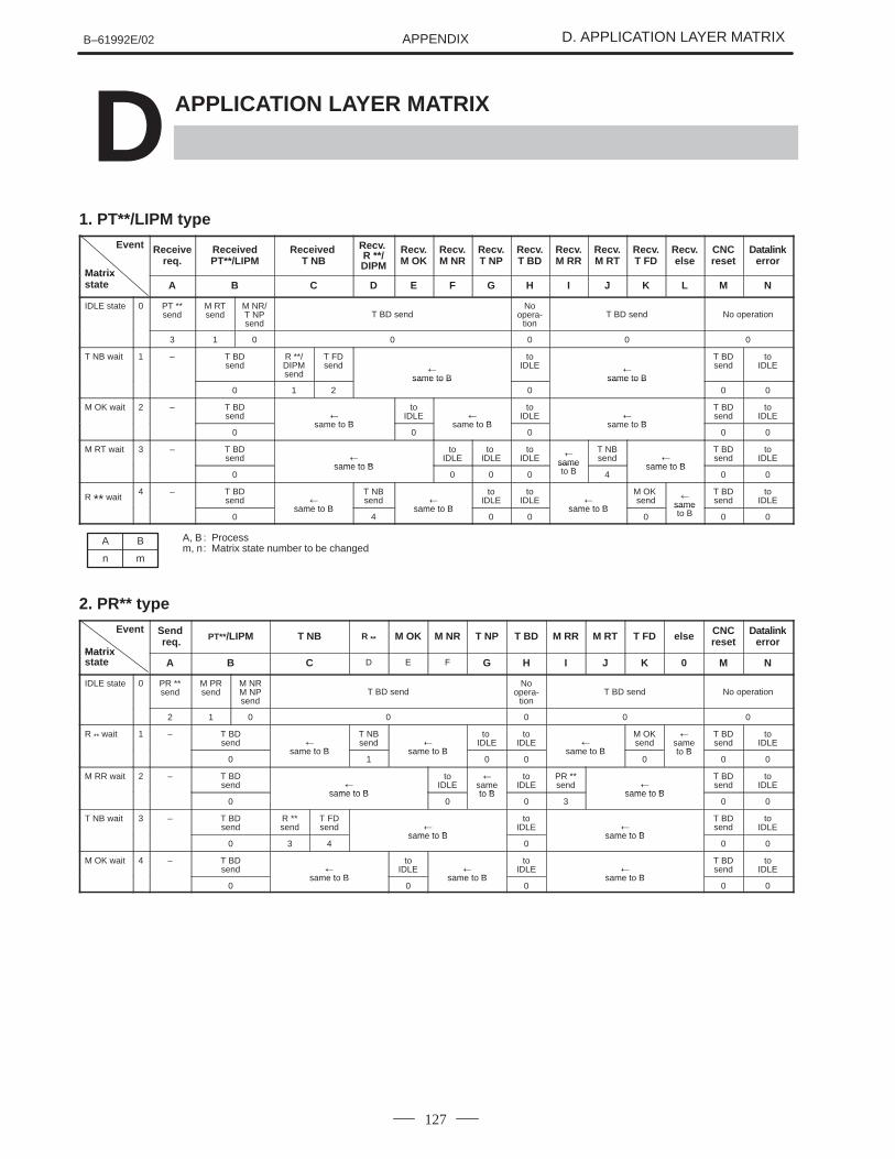
B–61992E/02 D. APPLICATION LAYER MATRIXAPPENDIX
127
D APPLICATION LAYER MATRIX
1. PT**/LIPM typeEvent
Matrix
Receivereq.
ReceivedPT**/LIPM
Received T NB
Recv. R **/DIPM
Recv.M OK
Recv.M NR
Recv.T NP
Recv.T BD
Recv.M RR
Recv.M RT
Recv.T FD
Recv.else
CNCreset
Datalinkerror
Matrix state A B C D E F G H I J K L M N
IDLE state 0 PT **send
M RTsend
M NR/T NPsend
T BD sendNo
opera-tion
T BD send No operation
3 1 0 0 0 0 0
T NB wait 1 – T BDsend
R **/DIPMsend
T FDsend �
same to B
toIDLE �
same to B
T BDsend
toIDLE
0 1 2same to B
0same to B
0 0
M OK wait 2 – T BDsend �
same to B
toIDLE �
same to B
toIDLE �
same to B
T BDsend
toIDLE
0same to B
0same to B
0same to B
0 0
M RT wait 3 – T BDsend �
same to B
toIDLE
to IDLE
toIDLE �
same
T NBsend �
same to B
T BDsend
toIDLE
0same to B
0 0 0sameto B 4
same to B0 0
R ** wait4 – T BD
send �same to B
T NBsend �
same to B
toIDLE
toIDLE �
same to B
M OK send �
same
T BDsend
toIDLE
0same to B
4same to B
0 0same to B
0sameto B 0 0
A, B : Processm, n: Matrix state number to be changed
A B
n m
2. PR** typeEvent
Matrix
Send req. PT**/LIPM T NB R ** M OK M NR T NP T BD M RR M RT T FD else CNC
resetDatalink
errorMatrix state A B C D E F G H I J K 0 M N
IDLE state 0 PR **send
M PRsend
M NRM NPsend
T BD sendNo
opera-tion
T BD send No operation
2 1 0 0 0 0 0
R ** wait 1 – T BDsend �
same to B
T NBsend �
same to B
to IDLE
toIDLE �
same to B
M OKsend
�sameto B
T BDsend
toIDLE
0same to B
1same to B
0 0same to B
0to B
0 0
M RR wait 2 – T BDsend �
same to B
toIDLE
�sameto B
toIDLE
PR **send �
same to B
T BDsend
toIDLE
0same to B
0to B
0 3same to B
0 0
T NB wait 3 – T BDsend
R **send
T FDsend �
same to B
toIDLE �
same to B
T BDsend
toIDLE
0 3 4same to B
0same to B
0 0
M OK wait 4 – T BDsend �
same to B
toIDLE �
same to B
toIDLE �
same to B
T BDsend
toIDLE
0same to B
0same to B
0same to B
0 0
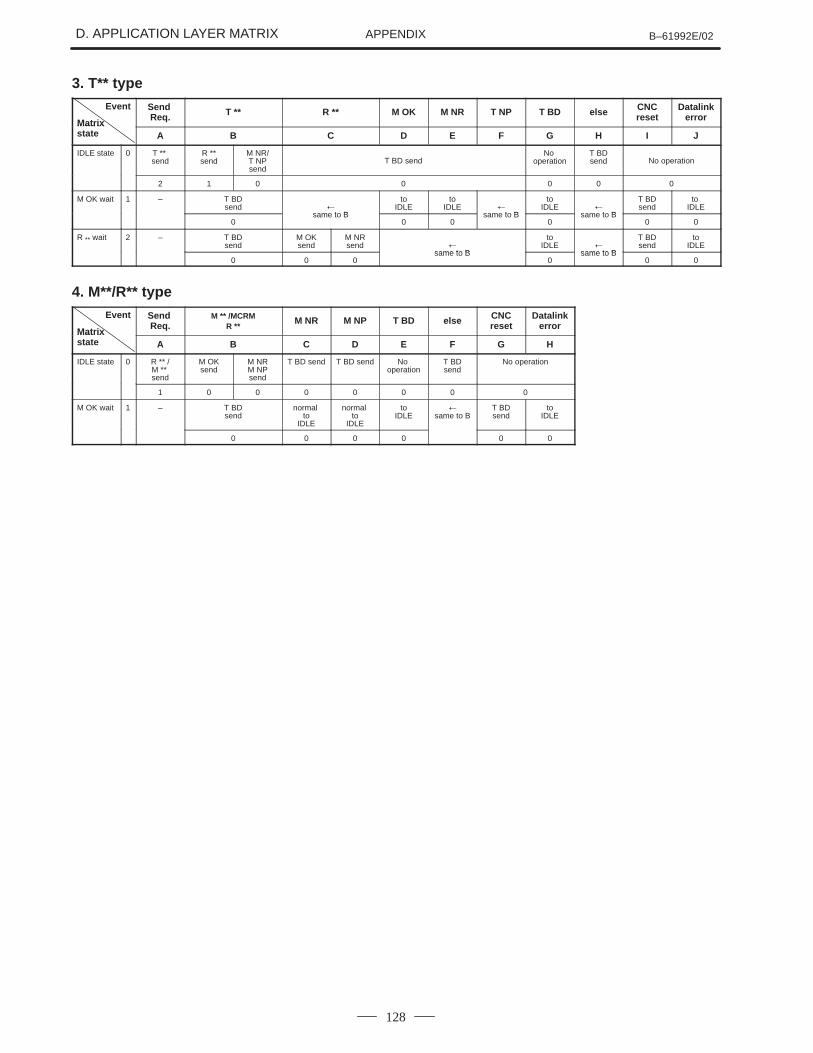
D. APPLICATION LAYER MATRIX B–61992E/02APPENDIX
128
3. T** typeEvent
Matrix
Send Req. T ** R ** M OK M NR T NP T BD else CNC
resetDatalink
errorMatrix state A B C D E F G H I J
IDLE state 0 T ** send
R **send
M NR/T NPsend
T BD sendNo
operationT BDsend No operation
2 1 0 0 0 0 0
M OK wait 1 – T BDsend �
same to B
toIDLE
toIDLE �
same to B
toIDLE �
same to B
T BDsend
to IDLE
0same to B
0 0same to B
0same to B
0 0
R ** wait 2 – T BDsend
M OKsend
M NRsend �
same to B
toIDLE �
same to B
T BDsend
toIDLE
0 0 0same to B
0same to B
0 0
4. M**/R** typeEvent
Matrix
Send Req.
M ** /MCRMR **
M NR M NP T BD else CNCreset
Datalinkerror
Matrix state A B C D E F G H
IDLE state 0 R ** /M ** send
M OKsend
M NRM NPsend
T BD send T BD send No operation
T BDsend
No operation
1 0 0 0 0 0 0 0
M OK wait 1 – T BDsend
normal to
IDLE
normal to
IDLE
toIDLE
�same to B
T BDsend
toIDLE
0 0 0 0 0 0

B–61992E/02 E. ALARM MESSAGESAPPENDIX
129
E ALARM MESSAGES
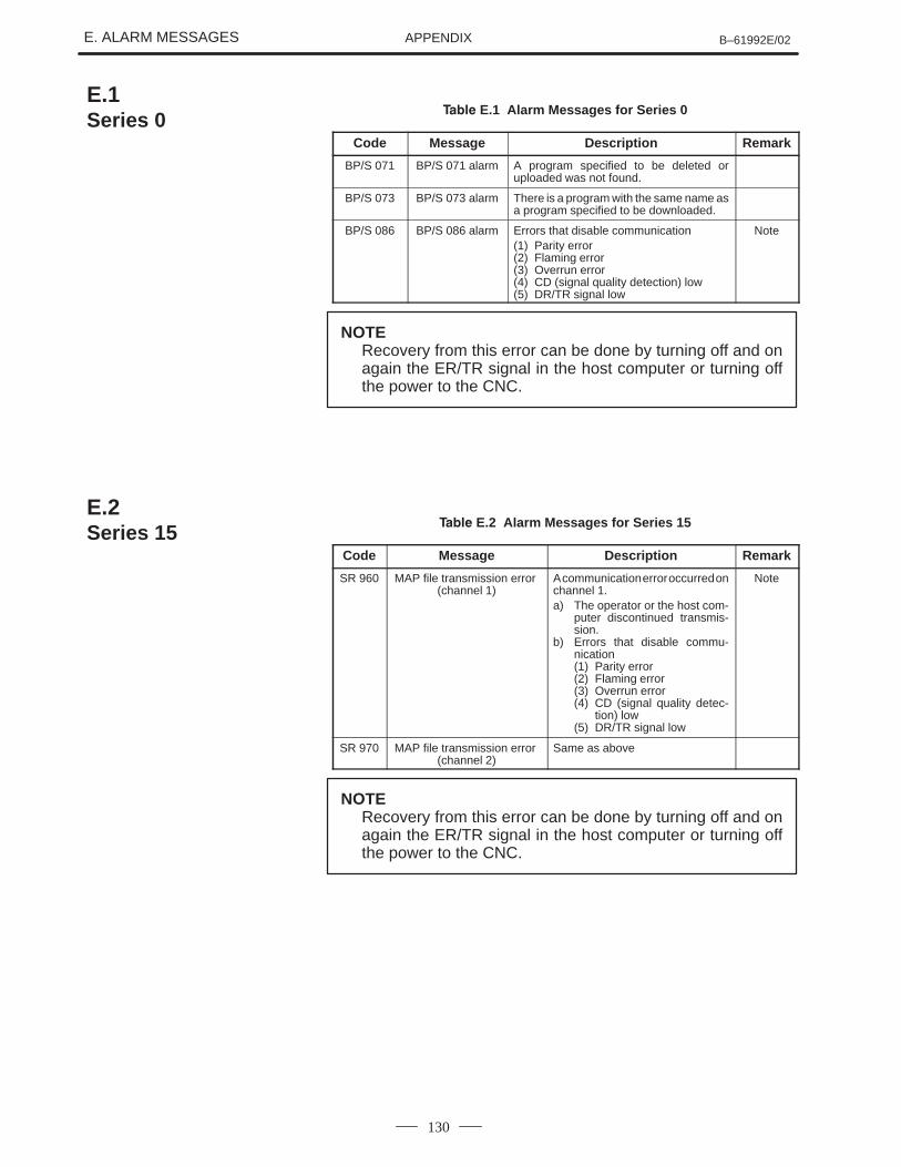
E. ALARM MESSAGES B–61992E/02APPENDIX
130
����� E.1 Alarm Messages for Series 0
Code Message Description Remark
BP/S 071 BP/S 071 alarm A program specified to be deleted oruploaded was not found.
BP/S 073 BP/S 073 alarm There is a program with the same name asa program specified to be downloaded.
BP/S 086 BP/S 086 alarm Errors that disable communication(1) Parity error(2) Flaming error(3) Overrun error(4) CD (signal quality detection) low(5) DR/TR signal low
Note
NOTERecovery from this error can be done by turning off and onagain the ER/TR signal in the host computer or turning offthe power to the CNC.
����� E.2 Alarm Messages for Series 15
Code Message Description Remark
SR 960 MAP file transmission error (channel 1)
A communication error occurred onchannel 1.a) The operator or the host com-
puter discontinued transmis-sion.
b) Errors that disable commu-nication(1) Parity error(2) Flaming error(3) Overrun error(4) CD (signal quality detec-
tion) low(5) DR/TR signal low
Note
SR 970 MAP file transmission error (channel 2)
Same as above
NOTERecovery from this error can be done by turning off and onagain the ER/TR signal in the host computer or turning offthe power to the CNC.
E.1Series 0
E.2Series 15
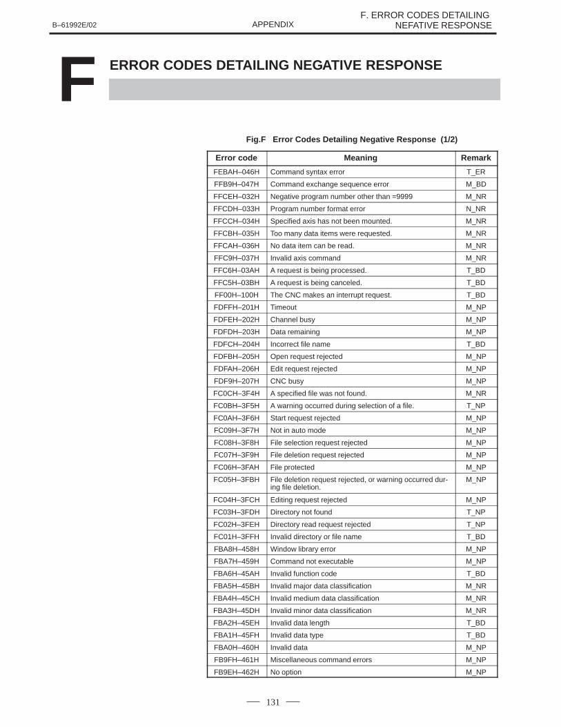
B–61992E/02F. ERROR CODES DETAILING
NEFATIVE RESPONSEAPPENDIX
131
F ERROR CODES DETAILING NEGATIVE RESPONSE
Fig.F Error Codes Detailing Negative Response (1/2)
Error code Meaning Remark
FEBAH–046H Command syntax error T_ER
FFB9H–047H Command exchange sequence error M_BD
FFCEH–032H Negative program number other than =9999 M_NR
FFCDH–033H Program number format error N_NR
FFCCH–034H Specified axis has not been mounted. M_NR
FFCBH–035H Too many data items were requested. M_NR
FFCAH–036H No data item can be read. M_NR
FFC9H–037H Invalid axis command M_NR
FFC6H–03AH A request is being processed. T_BD
FFC5H–03BH A request is being canceled. T_BD
FF00H–100H The CNC makes an interrupt request. T_BD
FDFFH–201H Timeout M_NP
FDFEH–202H Channel busy M_NP
FDFDH–203H Data remaining M_NP
FDFCH–204H Incorrect file name T_BD
FDFBH–205H Open request rejected M_NP
FDFAH–206H Edit request rejected M_NP
FDF9H–207H CNC busy M_NP
FC0CH–3F4H A specified file was not found. M_NR
FC0BH–3F5H A warning occurred during selection of a file. T_NP
FC0AH–3F6H Start request rejected M_NP
FC09H–3F7H Not in auto mode M_NP
FC08H–3F8H File selection request rejected M_NP
FC07H–3F9H File deletion request rejected M_NP
FC06H–3FAH File protected M_NP
FC05H–3FBH File deletion request rejected, or warning occurred dur-ing file deletion.
M_NP
FC04H–3FCH Editing request rejected M_NP
FC03H–3FDH Directory not found T_NP
FC02H–3FEH Directory read request rejected T_NP
FC01H–3FFH Invalid directory or file name T_BD
FBA8H–458H Window library error M_NP
FBA7H–459H Command not executable M_NP
FBA6H–45AH Invalid function code T_BD
FBA5H–45BH Invalid major data classification M_NR
FBA4H–45CH Invalid medium data classification M_NR
FBA3H–45DH Invalid minor data classification M_NR
FBA2H–45EH Invalid data length T_BD
FBA1H–45FH Invalid data type T_BD
FBA0H–460H Invalid data M_NP
FB9FH–461H Miscellaneous command errors M_NP
FB9EH–462H No option M_NP
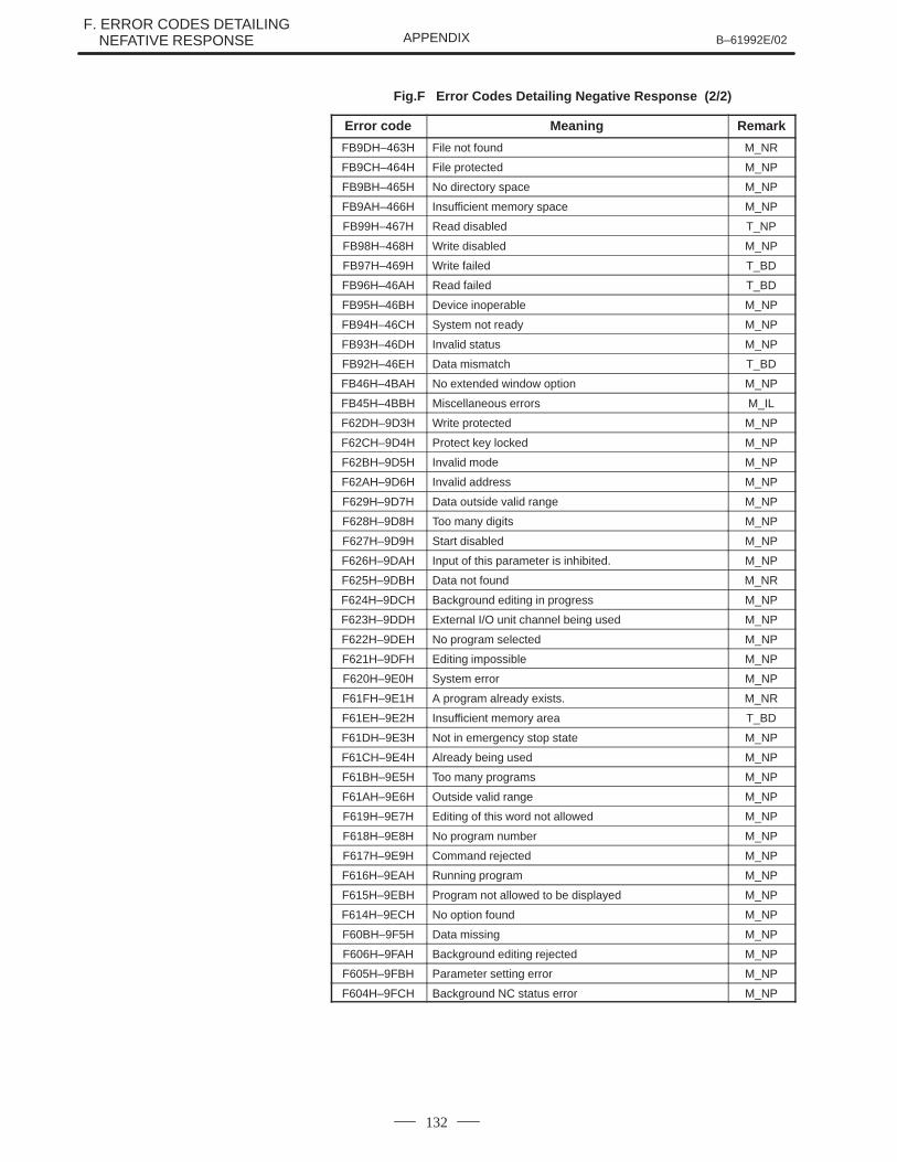
F. ERROR CODES DETAILING F. NEFATIVE RESPONSE B–61992E/02APPENDIX
132
Fig.F Error Codes Detailing Negative Response (2/2)
Error code RemarkMeaning
FB9DH–463H File not found M_NR
FB9CH–464H File protected M_NP
FB9BH–465H No directory space M_NP
FB9AH–466H Insufficient memory space M_NP
FB99H–467H Read disabled T_NP
FB98H–468H Write disabled M_NP
FB97H–469H Write failed T_BD
FB96H–46AH Read failed T_BD
FB95H–46BH Device inoperable M_NP
FB94H–46CH System not ready M_NP
FB93H–46DH Invalid status M_NP
FB92H–46EH Data mismatch T_BD
FB46H–4BAH No extended window option M_NP
FB45H–4BBH Miscellaneous errors M_IL
F62DH–9D3H Write protected M_NP
F62CH–9D4H Protect key locked M_NP
F62BH–9D5H Invalid mode M_NP
F62AH–9D6H Invalid address M_NP
F629H–9D7H Data outside valid range M_NP
F628H–9D8H Too many digits M_NP
F627H–9D9H Start disabled M_NP
F626H–9DAH Input of this parameter is inhibited. M_NP
F625H–9DBH Data not found M_NR
F624H–9DCH Background editing in progress M_NP
F623H–9DDH External I/O unit channel being used M_NP
F622H–9DEH No program selected M_NP
F621H–9DFH Editing impossible M_NP
F620H–9E0H System error M_NP
F61FH–9E1H A program already exists. M_NR
F61EH–9E2H Insufficient memory area T_BD
F61DH–9E3H Not in emergency stop state M_NP
F61CH–9E4H Already being used M_NP
F61BH–9E5H Too many programs M_NP
F61AH–9E6H Outside valid range M_NP
F619H–9E7H Editing of this word not allowed M_NP
F618H–9E8H No program number M_NP
F617H–9E9H Command rejected M_NP
F616H–9EAH Running program M_NP
F615H–9EBH Program not allowed to be displayed M_NP
F614H–9ECH No option found M_NP
F60BH–9F5H Data missing M_NP
F606H–9FAH Background editing rejected M_NP
F605H–9FBH Parameter setting error M_NP
F604H–9FCH Background NC status error M_NP

B–61992E/02 G. MAINTENANCEAPPENDIX
133
GMAINTENANCE
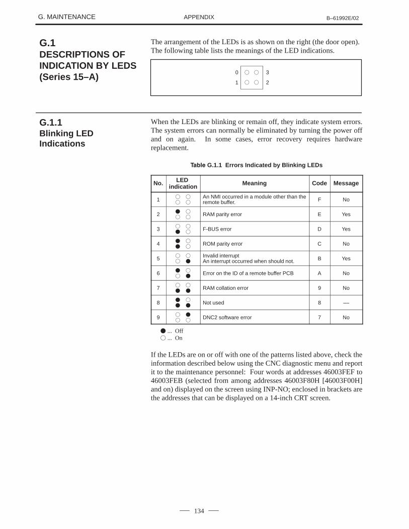
G. MAINTENANCE B–61992E/02APPENDIX
134
The arrangement of the LEDs is as shown on the right (the door open).The following table lists the meanings of the LED indications.
0
1
3
2
� �
� �
When the LEDs are blinking or remain off, they indicate system errors.The system errors can normally be eliminated by turning the power offand on again. In some cases, error recovery requires hardwarereplacement.
����� G.1.1 Errors Indicated by Blinking LEDs
No. LED indication Meaning Code Message
1 �
�
�
�
An NMI occurred in a module other than theremote buffer. F No
2 �
�
�
�RAM parity error E Yes
3 �
�
�
�F-BUS error D Yes
4 �
�
�
�ROM parity error C No
5 �
�
�
�
Invalid interruptAn interrupt occurred when should not. B Yes
6 �
�
�
�Error on the ID of a remote buffer PCB A No
7 �
�
�
�RAM collation error 9 No
8 �
�
�
�Not used 8 ––
9 �
�
�
�DNC2 software error 7 No
� ... Off� ... On
If the LEDs are on or off with one of the patterns listed above, check theinformation described below using the CNC diagnostic menu and reportit to the maintenance personnel: Four words at addresses 46003FEF to46003FEB (selected from among addresses 46003F80H [46003F00H]and on) displayed on the screen using INP-NO; enclosed in brackets arethe addresses that can be displayed on a 14-inch CRT screen.
G.1DESCRIPTIONS OFINDICATION BY LEDS(Series 15–A)
G.1.1Blinking LEDIndications
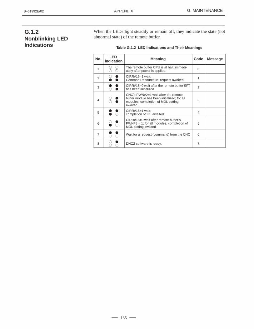
B–61992E/02 G. MAINTENANCEAPPENDIX
135
When the LEDs light steadily or remain off, they indicate the state (notabnormal state) of the remote buffer.
����� G.1.2 LED Indications and Their Meanings
No. LED indication Meaning Code Message
1 �
�
�
�
The remote buffer CPU is at halt, immedi-ately after power is applied. F
2 �
�
�
�
CIRR#15=1 wait; Common Resource Irt. request awaited 1
3 �
�
�
�
CIRR#15=0 wait after the remote buffer SFThas been initialized 2
4 �
�
�
�
CNC’s PWN#2=1 wait after the remotebuffer module has been initialized; for allmodules, completion of MDL settingawaited.
3
5 �
�
�
�
CIRR#15=1 wait; completion of IPL awaited 4
6 �
�
�
�
CIRR#15=0 wait after remote buffer’sPWN#3 = 1; for all modules, completion ofMDL setting awaited
5
7 �
�
�
�Wait for a request (command) from the CNC 6
8 �
�
�
�DNC2 software is ready. 7
G.1.2Nonblinking LEDIndications
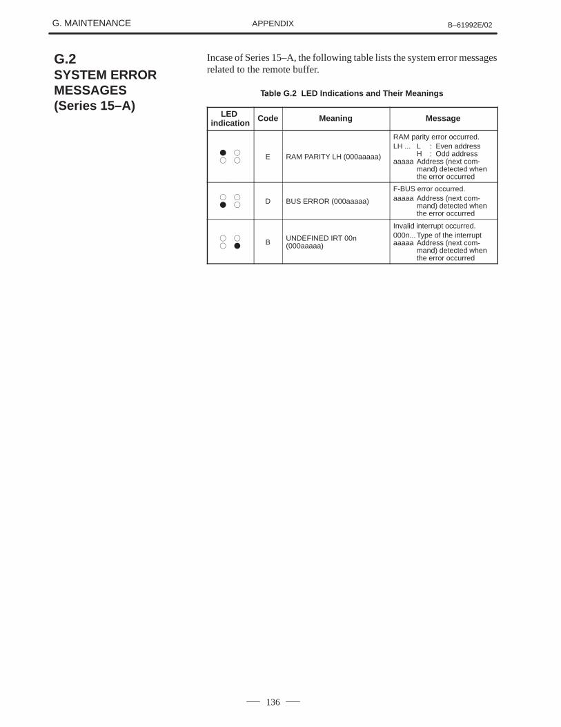
G. MAINTENANCE B–61992E/02APPENDIX
136
Incase of Series 15–A, the following table lists the system error messagesrelated to the remote buffer.
����� G.2 LED Indications and Their Meanings
LED indication Code Meaning Message
�
�
�
�E RAM PARITY LH (000aaaaa)
RAM parity error occurred.LH ... L : Even address
H : Odd addressaaaaa Address (next com-
mand) detected whenthe error occurred
�
�
�
�D BUS ERROR (000aaaaa)
F-BUS error occurred.aaaaa Address (next com-
mand) detected whenthe error occurred
�
�
�
�B UNDEFINED IRT 00n
(000aaaaa)
Invalid interrupt occurred.000n...Type of the interruptaaaaa Address (next com-
mand) detected whenthe error occurred
G.2SYSTEM ERRORMESSAGES (Series 15–A)
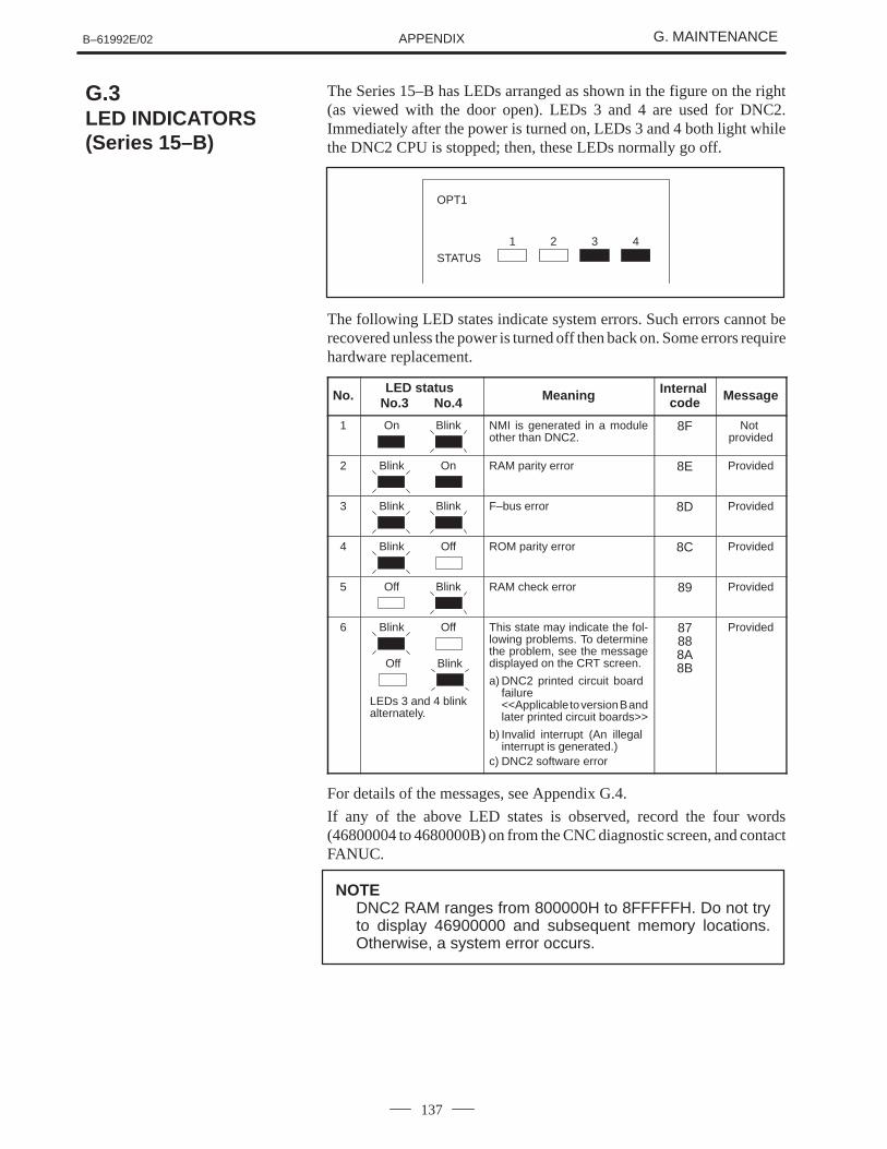
B–61992E/02 G. MAINTENANCEAPPENDIX
137
The Series 15–B has LEDs arranged as shown in the figure on the right(as viewed with the door open). LEDs 3 and 4 are used for DNC2.Immediately after the power is turned on, LEDs 3 and 4 both light whilethe DNC2 CPU is stopped; then, these LEDs normally go off.
OPT1
STATUS1 2 3 4
The following LED states indicate system errors. Such errors cannot berecovered unless the power is turned off then back on. Some errors requirehardware replacement.
No. LED status No.3 No.4 Meaning Internal
code Message
1 On Blink NMI is generated in a moduleother than DNC2.
8F Not provided
2 Blink On RAM parity error 8E Provided
3 Blink Blink F–bus error 8D Provided
4 Blink Off ROM parity error 8C Provided
5 Off Blink RAM check error 89 Provided
6 Blink
Off
Off
Blink
LEDs 3 and 4 blinkalternately.
This state may indicate the fol-lowing problems. To determinethe problem, see the messagedisplayed on the CRT screen.
a) DNC2 printed circuit board failure<<Applicable to version B andlater printed circuit boards>>
b) Invalid interrupt (An illegal interrupt is generated.)
c) DNC2 software error
87888A8B
Provided
For details of the messages, see Appendix G.4.
If any of the above LED states is observed, record the four words(46800004 to 4680000B) on from the CNC diagnostic screen, and contactFANUC.
NOTEDNC2 RAM ranges from 800000H to 8FFFFFH. Do not tryto display 46900000 and subsequent memory locations.Otherwise, a system error occurs.
G.3LED INDICATORS(Series 15–B)
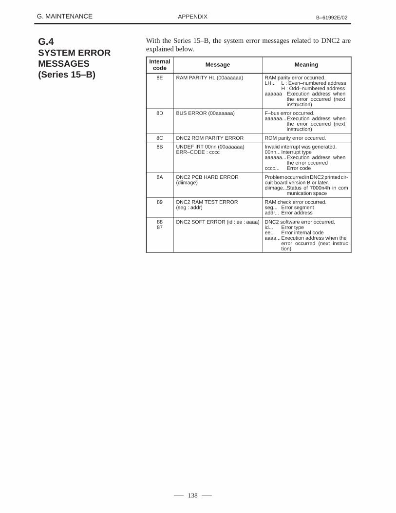
G. MAINTENANCE B–61992E/02APPENDIX
138
With the Series 15–B, the system error messages related to DNC2 areexplained below.
Internalcode Message Meaning
8E RAM PARITY HL (00aaaaaa) RAM parity error occurred.LH... L : Even–numbered address
H : Odd–numbered addressaaaaaa Execution address when
the error occurred (next instruction)
8D BUS ERROR (00aaaaaa) F–bus error occurred.aaaaaa...Execution address when
the error occurred (next instruction)
8C DNC2 ROM PARITY ERROR ROM parity error occurred.
8B UNDEF IRT 00nn (00aaaaaa) ERR–CODE : cccc
Invalid interrupt was generated.00nn... Interrupt typeaaaaaa...Execution address when
the error occurredcccc... Error code
8A DNC2 PCB HARD ERROR (diimage)
Problem occurred in DNC2 printed cir-cuit board version B or later.diimage...Status of 7000n4h in com
munication space
89 DNC2 RAM TEST ERROR (seg : addr)
RAM check error occurred.seg... Error segmentaddr... Error address
8887
DNC2 SOFT ERROR (id : ee : aaaa) DNC2 software error occurred.id... Error typeee... Error internal codeaaaa...Execution address when the
error occurred (next instruction)
G.4SYSTEM ERRORMESSAGES (Series 15–B)
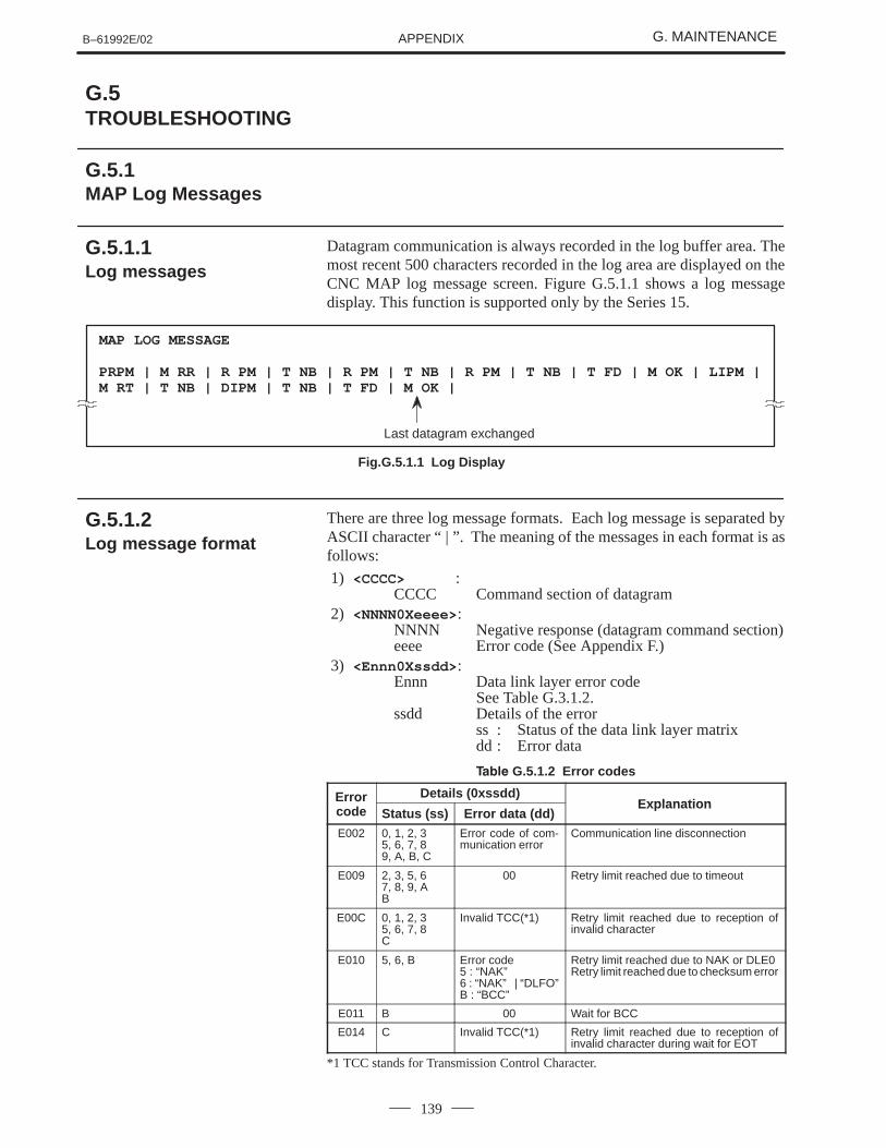
B–61992E/02 G. MAINTENANCEAPPENDIX
139
Datagram communication is always recorded in the log buffer area. Themost recent 500 characters recorded in the log area are displayed on theCNC MAP log message screen. Figure G.5.1.1 shows a log messagedisplay. This function is supported only by the Series 15.
MAP LOG MESSAGE
PRPM | M RR | R PM | T NB | R PM | T NB | R PM | T NB | T FD | M OK | LIPM |M RT | T NB | DIPM | T NB | T FD | M OK |
Last datagram exchanged
Fig.G.5.1.1 Log Display
There are three log message formats. Each log message is separated byASCII character “ | ”. The meaning of the messages in each format is asfollows:
1) <CCCC> :CCCC Command section of datagram
2) <NNNN0Xeeee>:NNNN Negative response (datagram command section)eeee Error code (See Appendix F.)
3) <Ennn0Xssdd> :Ennn Data link layer error code
See Table G.3.1.2.ssdd Details of the error
ss : Status of the data link layer matrixdd : Error data
����� G.5.1.2 Error codes
Error Details (0xssdd)ExplanationError
code Status (ss) Error data (dd)Explanation
E002 0, 1, 2, 35, 6, 7, 89, A, B, C
Error code of com-munication error
Communication line disconnection
E009 2, 3, 5, 67, 8, 9, AB
00 Retry limit reached due to timeout
E00C 0, 1, 2, 35, 6, 7, 8C
Invalid TCC(*1) Retry limit reached due to reception ofinvalid character
E010 5, 6, B Error code5 : “NAK”6 : “NAK” | “DLFO”B : “BCC”
Retry limit reached due to NAK or DLE0Retry limit reached due to checksum error
E011 B 00 Wait for BCC
E014 C Invalid TCC(*1) Retry limit reached due to reception ofinvalid character during wait for EOT
*1 TCC stands for Transmission Control Character.
G.5TROUBLESHOOTING
G.5.1MAP Log Messages
G.5.1.1 Log messages
G.5.1.2 Log message format
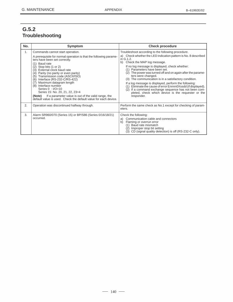
G. MAINTENANCE B–61992E/02APPENDIX
140
No. Symptom Check procedure
1. Commands cannot start operation.
A prerequisite for normal operation is that the following parame-ters have been set correctly.(1) Baud rate(2) Stop bits (1 or 2)(3) External clock baud rate(4) Parity (no parity or even parity)(5) Transmission code (ASCII/ISO)(6) Interface (RS-232-C/RS-422)(7) Maximum datagram length(8) Interface number
Series 0 : I/O=10Series 15: No. 20, 21, 22, 23=4
(Note) If a parameter value is out of the valid range, thedefault value is used. Check the default value for each device.
Troubleshoot according to the following procedure.a) Check whether the LED indication pattern is No. 8 describedin G.1.2.b) Check the MAP log message.
If no log message is displayed, check whether:(1) Parameters have been set.(2) The power was turned off and on again after the parame-
ters were changed.(3) The communication is in a satisfactory condition.If a log message is displayed, perform the following:(1) Eliminate the cause of error Ennnn0Xssdd (if displayed).(2) If a command exchange sequence has not been com-
pleted, check which device is the requester or theresponder.
2. Operation was discontinued halfway through. Perform the same check as No.1 except for checking of param-eters.
3. Alarm SR960/070 (Series 15) or BP/S86 (Series 0/16/18/21)occurred.
Check the following:a) Communication cable and connectorsb) Flaming or overrun error
(1) Baud rate mismatch(2) Improper stop bit setting(3) CD (signal quality detection) is off (RS-232-C only).
G.5.2Troubleshooting
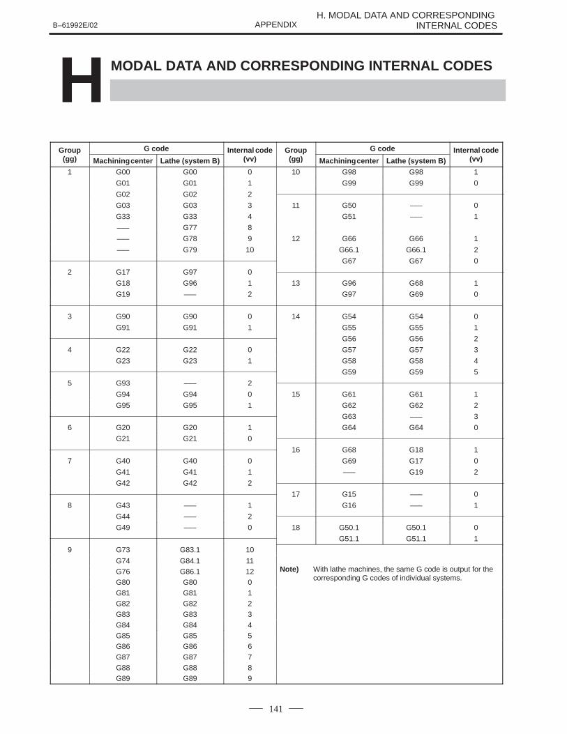
B–61992E/02H. MODAL DATA AND CORRESPONDING
INTERNAL CODESAPPENDIX
141
H MODAL DATA AND CORRESPONDING INTERNAL CODES
Group G code Internal code Group G code Internal codep(gg) Machining center Lathe (system B) (vv)
p(gg) Machining center Lathe (system B) (vv)
1 G00 G00 0 10 G98 G98 1
G01 G01 1 G99 G99 0
G02 G02 2
G03 G03 3 11 G50 ––– 0
G33 G33 4 G51 ––– 1
––– G77 8
––– G78 9 12 G66 G66 1
––– G79 10 G66.1 G66.1 2
G67 G67 0
2 G17 G97 0
G18 G96 1 13 G96 G68 1
G19 ––– 2 G97 G69 0
3 G90 G90 0 14 G54 G54 0
G91 G91 1 G55 G55 1
G56 G56 2
4 G22 G22 0 G57 G57 3
G23 G23 1 G58 G58 4
G59 G59 5
5 G93 ––– 2
G94 G94 0 15 G61 G61 1
G95 G95 1 G62 G62 2
G63 ––– 3
6 G20 G20 1 G64 G64 0
G21 G21 0
16 G68 G18 1
7 G40 G40 0 G69 G17 0
G41 G41 1 ––– G19 2
G42 G42 2
17 G15 ––– 0
8 G43 ––– 1 G16 ––– 1
G44 ––– 2
G49 ––– 0 18 G50.1 G50.1 0
G51.1 G51.1 1
9 G73 G83.1 10
G74 G84.1 11) G fG76 G86.1 12 Note) With lathe machines, the same G code is output for the
corresponding G codes of individual systemsG80 G80 0
corresponding G codes of individual systems.
G81 G81 1G82 G82 2G83 G83 3
G84 G84 4G85 G85 5G86 G86 6G87 G87 7
G88 G88 8G89 G89 9
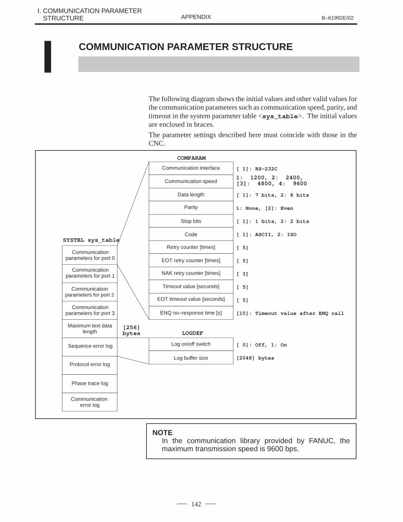
I. COMMUNICATION PARAMETER I. STRUCTURE B–61992E/02APPENDIX
142
I COMMUNICATION PARAMETER STRUCTURE
The following diagram shows the initial values and other valid values forthe communication parameters such as communication speed, parity, andtimeout in the system parameter table <sys_table >. The initial valuesare enclosed in braces.
The parameter settings described here must coincide with those in theCNC.
SYSTBL sys_table
COMPARAM
[ 1]: RS-232CCommunication interface
Communication speed
[ 1]: 7 bits, 2: 8 bitsData length
1: None, [2]: EvenParity
[ 1]: 1 bits, 2: 2 bitsStop bits
[ 1]: ASCII, 2: ISOCode
[ 5]Retry counter [times]
[ 5]EOT retry counter [times]
[ 3]NAK retry counter [times]
[ 5]Timeout value [seconds]
[ 5]EOT timeout value [seconds]
Communicationparameters for port 0
Communicationparameters for port 1
Communicationparameters for port 2
Communicationparameters for port 3
[256]bytes
Maximum text datalength
Sequence error log
Protocol error log
Phase trace log
Communication error log
LOGDEF
[ 0]: Off, 1: OnLog on/off switch
[2048] bytesLog buffer size
1: 1200, 2: 2400, [3]: 4800, 4: 9600
[10]: Timeout value after ENQ callENQ no–response time [s]
NOTEIn the communication library provided by FANUC, themaximum transmission speed is 9600 bps.
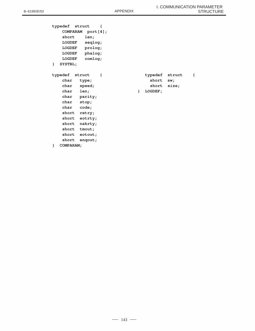
B–61992E/02I. COMMUNICATION PARAMETER
STRUCTUREAPPENDIX
143
typedef struct { COMPARAM port[4]; short len; LOGDEF seqlog; LOGDEF prolog; LOGDEF phalog; LOGDEF comlog;} SYSTBL;
typedef struct { typedef struct { char type; short sw; char speed; short size; char len; } LOGDEF; char parity; char stop; char code; short retry; short eotrty; short nakrty; short tmout; short eotout; short enqout;} COMPARAM;
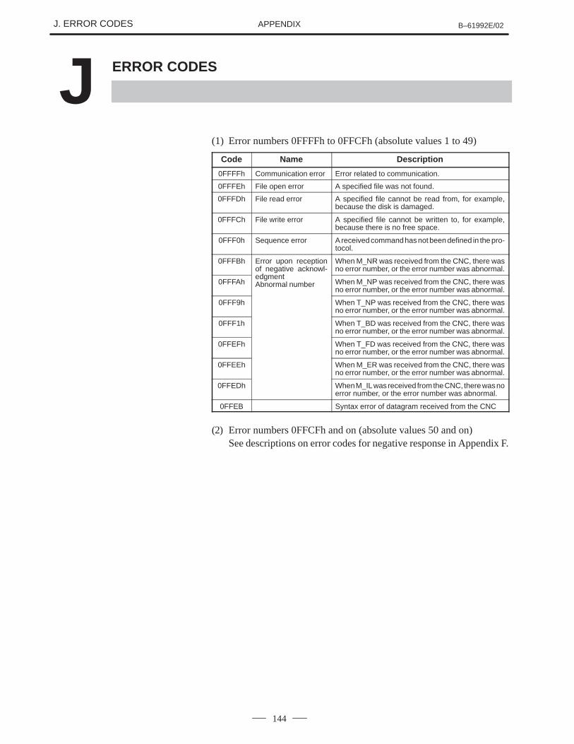
J. ERROR CODES B–61992E/02APPENDIX
144
J ERROR CODES
(1) Error numbers 0FFFFh to 0FFCFh (absolute values 1 to 49)
Code Name Description
0FFFFh Communication error Error related to communication.
0FFFEh File open error A specified file was not found.
0FFFDh File read error A specified file cannot be read from, for example,because the disk is damaged.
0FFFCh File write error A specified file cannot be written to, for example,because there is no free space.
0FFF0h Sequence error A received command has not been defined in the pro-tocol.
0FFFBh Error upon receptionof negative acknowl-edgment
When M_NR was received from the CNC, there wasno error number, or the error number was abnormal.
0FFFAhedgmentAbnormal number When M_NP was received from the CNC, there was
no error number, or the error number was abnormal.
0FFF9h When T_NP was received from the CNC, there wasno error number, or the error number was abnormal.
0FFF1h When T_BD was received from the CNC, there wasno error number, or the error number was abnormal.
0FFEFh When T_FD was received from the CNC, there wasno error number, or the error number was abnormal.
0FFEEh When M_ER was received from the CNC, there wasno error number, or the error number was abnormal.
0FFEDh When M_IL was received from the CNC, there was noerror number, or the error number was abnormal.
0FFEB Syntax error of datagram received from the CNC
(2) Error numbers 0FFCFh and on (absolute values 50 and on)See descriptions on error codes for negative response in Appendix F.

B–61992E/02 K. DEMONSTRATION PROGRAMAPPENDIX
145
K DEMONSTRATION PROGRAM

K. DEMONSTRATION PROGRAM B–61992E/02APPENDIX
146
This demonstration program is supplied as a sample program of thecommunication library. This program uses several communicationlibrary functions (the downloading, program deletion, and PMC dataread/write functions) to perform simple schedule operation in memorymode.
Since the program requires the Series 0–MC and a special ladder, merelyexecuting the program on the supplied floppy disk does not allowfunctions 4, 5, 6, 8, and 9 in the command list to be performed correctly.
K.1OUTLINE OFFUNCTIONS
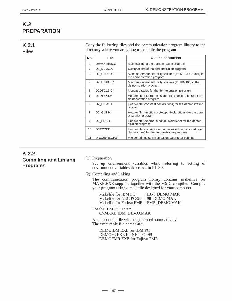
B–61992E/02 K. DEMONSTRATION PROGRAMAPPENDIX
147
Copy the following files and the communication program library to thedirectory where you are going to compile the program.
No. File Outline of function
1 DEMO_MAN.C Main routine of the demonstration program
2 D2_DEMO.C Subfunctions of the demonstration program
3 D2_UTL98.C Machine-dependent utility routines (for NEC PC-9801) inthe demonstration program
4 D2_UTIBM.C Machine-dependent utility routines (for IBN PC) in thedemonstration program
5 D2DTGLB.C Message tables for the demonstration program
6 D2DTEXT.H Header file (external message table declarations) for thedemonstration program
7 D2_DEMO.H Header file (constant declarations) for the demonstrationprogram
8 D2_GLB.H Header file (function prototype declarations) for the dem-onstration program
9 D2_PRT.H Header file (external function definitions) for the demon-stration program
10 DNC2DEF.H Header file (communication package functions and typedeclarations) for the demonstration program
11 DNC2SYS.CFG File containing communication parameter settings
(1) PreparationSet up environment variables while referring to setting ofenvironment variables described in III–3.3.
(2) Compiling and linkingThe communication program library contains makefiles forMAKE.EXE supplied together with the MS-C compiler. Compileyour program using a makefile designed for your computer.
Makefile for IBM PC : IBM_DEMO.MAKMakefile for NEC PC-98 : 98_DEMO.MAKMakefile for Fujitsu FMR : FMR_DEMO.MAK
For the IBM PC, enter:C>MAKE IBM_DEMO.MAK
An executable file will be generated automatically.The executable file names are:
DEMOIBM.EXE for IBM PCDEMO98.EXE for NEC PC-98DEMOFMR.EXE for Fujitsu FMR
K.2PREPARATION
K.2.1Files
K.2.2Compiling and LinkingPrograms
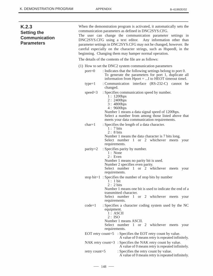
K. DEMONSTRATION PROGRAM B–61992E/02APPENDIX
148
When the demonstration program is activated, it automatically sets thecommunication parameters as defined in DNC2SYS.CFG.The user can change the communication parameter settings inDNC2SYS.CFG using a text editor. Any information other thanparameter settings in DNC2SYS.CFG may not be changed, however. Becareful especially on the character strings, such as HspeedI, in thebeginning. Changing them may hamper normal operation.
The details of the contents of the file are as follows:
(1) How to set the DNC2 system communication parametersport=0 : Indicates that the following settings belong to port 0.
To generate the parameters for port 1, duplicate allinformation from Hport = ...I to HEOT timeout timeI.
type=1 : Communication interface (RS-232-C) cannot bechanged.
speed=3 : Specifies communication speed by number.1 : 1200bps2 : 2400bps3 : 4800bps4 : 9600bps
Number 1 means a data signal speed of 1200bps.Select a number from among those listed above thatmeets your data communication requirements.
char=1 : Specifies the length of a data character.1 : 7 bits2 : 8 bits
Number 1 means the data character is 7 bits long.Select number 1 or 2 whichever meets yourrequirements.
parity=2 : Specifies parity by number.1 : None2 : Even
Number 1 means no parity bit is used.Number 2 specifies even parity.Select number 1 or 2 whichever meets yourrequirements.
stop bit=1 : Specifies the number of stop bits by number1 : 1 bit2 : 2 bits
Number 1 means one bit is used to indicate the end of atransmitted character.Select number 1 or 2 whichever meets yourrequirements.
code=1 : Specifies a character coding system used by the NCequipment.
1 : ASCII2 : ISO
Number 1 means ASCII.Select number 1 or 2 whichever meets yourrequirements.
EOT retry count=5 : Specifies the EOT retry count by value.A value of 0 means retry is repeated infinitely.
NAK retry count=3 : Specifies the NAK retry count by value.A value of 0 means retry is repeated infinitely.
retry count=5 : Specifies the retry count by value.A value of 0 means retry is repeated infinitely.
K.2.3Setting theCommunicationParameters
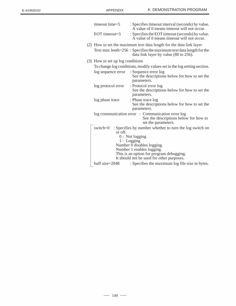
B–61992E/02 K. DEMONSTRATION PROGRAMAPPENDIX
149
timeout time=5 : Specifies timeout interval (seconds) by value.A value of 0 means timeout will not occur.
EOT timeout=5 : Specifies the EOT timeout (seconds) by value.A value of 0 means timeout will not occur.
(2) How to set the maximum text data length for the data link layerText max lenth=256 : Specifies the maximum text data length for the
data link layer by value (80 to 256).
(3) How to set up log conditionsTo change log conditions, modify values set in the log setting section.log sequence error : Sequence error log
See the descriptions below for how to set theparameters.
log protocol error : Protocol error logSee the descriptions below for how to set theparameters.
log phase trace : Phase trace logSee the descriptions below for how to set theparameters.
log communication error : Communication error logSee the descriptions below for how to set the parameters.
switch=0 : Specifies by number whether to turn the log switch onor off.
0 : Not logging1 : Logging
Number 0 disables logging.Number 1 enables logging.This is an option for program debugging.It should not be used for other purposes.
buff size=2048 : Specifies the maximum log file size in bytes.
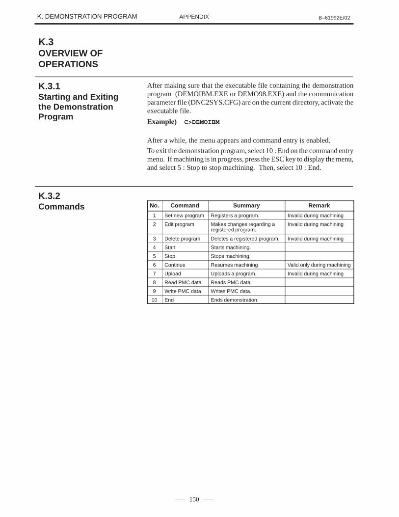
K. DEMONSTRATION PROGRAM B–61992E/02APPENDIX
150
After making sure that the executable file containing the demonstrationprogram (DEMOIBM.EXE or DEMO98.EXE) and the communicationparameter file (DNC2SYS.CFG) are on the current directory, activate theexecutable file.
Example) C>DEMOIBM
After a while, the menu appears and command entry is enabled.
To exit the demonstration program, select 10 : End on the command entrymenu. If machining is in progress, press the ESC key to display the menu,and select 5 : Stop to stop machining. Then, select 10 : End.
No. Command Summary Remark
1 Set new program Registers a program. Invalid during machining
2 Edit program Makes changes regarding aregistered program.
Invalid during machining
3 Delete program Deletes a registered program. Invalid during machining
4 Start Starts machining.
5 Stop Stops machining.
6 Continue Resumes machining Valid only during machining
7 Upload Uploads a program. Invalid during machining
8 Read PMC data Reads PMC data.
9 Write PMC data Writes PMC data.
10 End Ends demonstration.
K.3OVERVIEW OFOPERATIONS
K.3.1Starting and Exitingthe DemonstrationProgram
K.3.2Commands
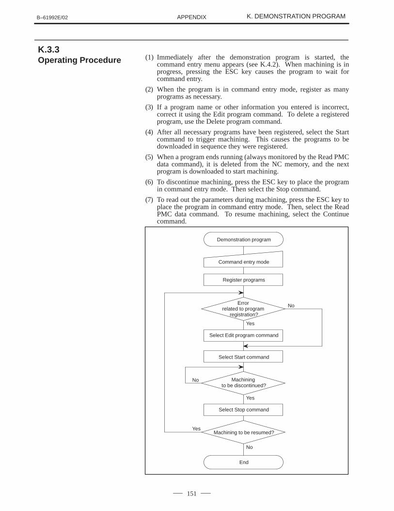
B–61992E/02 K. DEMONSTRATION PROGRAMAPPENDIX
151
(1) Immediately after the demonstration program is started, thecommand entry menu appears (see K.4.2). When machining is inprogress, pressing the ESC key causes the program to wait forcommand entry.
(2) When the program is in command entry mode, register as manyprograms as necessary.
(3) If a program name or other information you entered is incorrect,correct it using the Edit program command. To delete a registeredprogram, use the Delete program command.
(4) After all necessary programs have been registered, select the Startcommand to trigger machining. This causes the programs to bedownloaded in sequence they were registered.
(5) When a program ends running (always monitored by the Read PMCdata command), it is deleted from the NC memory, and the nextprogram is downloaded to start machining.
(6) To discontinue machining, press the ESC key to place the programin command entry mode. Then select the Stop command.
(7) To read out the parameters during machining, press the ESC key toplace the program in command entry mode. Then, select the ReadPMC data command. To resume machining, select the Continuecommand.
No
No
Yes
Yes
Demonstration program
Command entry mode
Register programs
Error related to program
registration?
Select Edit program command
Select Start command
No
Machining to be discontinued?
Select Stop command
YesMachining to be resumed?
End
K.3.3Operating Procedure
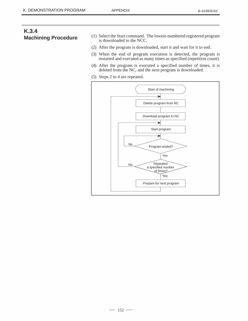
K. DEMONSTRATION PROGRAM B–61992E/02APPENDIX
152
(1) Select the Start command. The lowest-numbered registered programis downloaded to the NCC.
(2) After the program is downloaded, start it and wait for it to end.
(3) When the end of program execution is detected, the program isrestarted and executed as many times as specified (repetition count).
(4) After the program is executed a specified number of times, it isdeleted from the NC, and the next program is downloaded.
(5) Steps 2 to 4 are repeated.
Yes
No
Yes
Start of machining
Delete program from NC
Program ended?
Prepare for next program
Download program to NC
Start program
No Repeated a specified number
of times?
K.3.4Machining Procedure
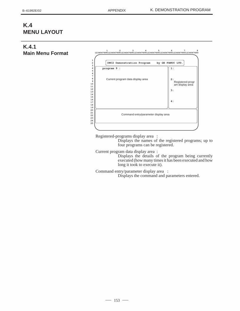
B–61992E/02 K. DEMONSTRATION PROGRAMAPPENDIX
153
1:
2:Registered-program display area
3:
4:
1 2 3 4 5 6 7 812345678901234567890123456789012345678901234567890123456789012345678901234567890
123456789
10111213141516171819202122232425
DNC2 Demonstration Program by GE FANUC LTD.
Command entry/parameter display area
program 9 :
Current program data display area
Registered-programs display area :Displays the names of the registered programs; up tofour programs can be registered.
Current program data display area :Displays the details of the program being currentlyexecuted (how many times it has been executed and howlong it took to execute it).
Command entry/parameter display area :Displays the command and parameters entered.
K.4MENU LAYOUT
K.4.1Main Menu Format
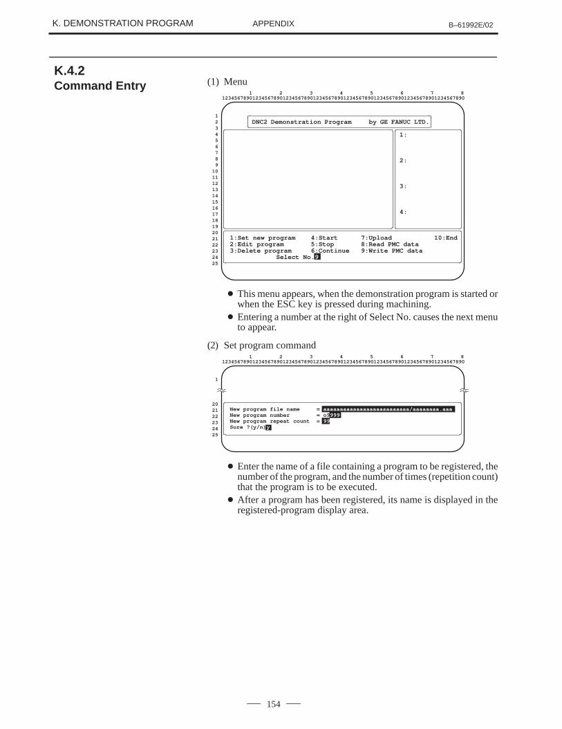
K. DEMONSTRATION PROGRAM B–61992E/02APPENDIX
154
(1) Menu
1:
2:
3:
4:
1 2 3 4 5 6 7 812345678901234567890123456789012345678901234567890123456789012345678901234567890
123456789
10111213141516171819202122232425
DNC2 Demonstration Program by GE FANUC LTD.
1:Set new program 4:Start 7:Upload 10:End2:Edit program 5:Stop 8:Read PMC data3:Delete program 6:Continue 9:Write PMC data
Select No. 9
� This menu appears, when the demonstration program is started orwhen the ESC key is pressed during machining.
� Entering a number at the right of Select No. causes the next menuto appear.
(2) Set program command1 2 3 4 5 6 7 8
12345678901234567890123456789012345678901234567890123456789012345678901234567890
1
202122232425
New program file name = aaaaaaaaaaaaaaaaaaaaaaaaaa/aaaaaaaa.aaaNew program number = o9 999New program repeat count = 99Sure ?(y/n) y
� Enter the name of a file containing a program to be registered, thenumber of the program, and the number of times (repetition count)that the program is to be executed.
� After a program has been registered, its name is displayed in theregistered-program display area.
K.4.2Command Entry
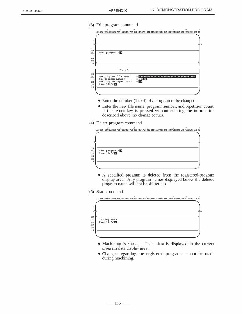
B–61992E/02 K. DEMONSTRATION PROGRAMAPPENDIX
155
(3) Edit program command1 2 3 4 5 6 7 8
12345678901234567890123456789012345678901234567890123456789012345678901234567890
1
202122232425
202122232425
New program file name = aaaaaaaaaaaaaaaaaaaaaaaaaa/aaaaaaaa.aaaNew program number = o9 999New program repeat count = 99Sure ?(y/n) y
Edit program ? 9
� Enter the number (1 to 4) of a program to be changed.� Enter the new file name, program number, and repetition count.
If the return key is pressed without entering the informationdescribed above, no change occurs.
(4) Delete program command1 2 3 4 5 6 7 8
12345678901234567890123456789012345678901234567890123456789012345678901234567890
1
202122232425
Edit program ? 9Sure ?(y/n) y
� A specified program is deleted from the registered-programdisplay area. Any program names displayed below the deletedprogram name will not be shifted up.
(5) Start command1 2 3 4 5 6 7 8
12345678901234567890123456789012345678901234567890123456789012345678901234567890
1
202122232425
Cutting startSure ?(y/n) y
� Machining is started. Then, data is displayed in the currentprogram data display area.
� Changes regarding the registered programs cannot be madeduring machining.
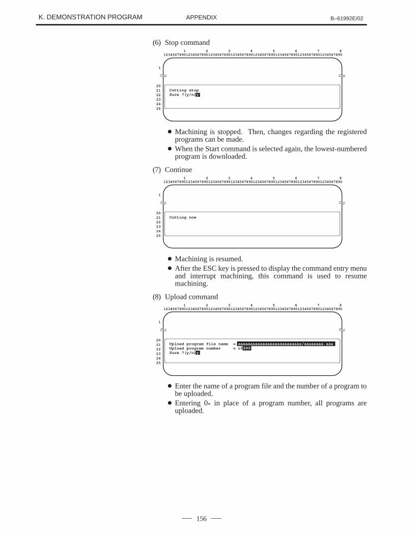
K. DEMONSTRATION PROGRAM B–61992E/02APPENDIX
156
(6) Stop command1 2 3 4 5 6 7 8
12345678901234567890123456789012345678901234567890123456789012345678901234567890
1
202122232425
Cutting stopSure ?(y/n) y
� Machining is stopped. Then, changes regarding the registeredprograms can be made.
� When the Start command is selected again, the lowest-numberedprogram is downloaded.
(7) Continue1 2 3 4 5 6 7 8
12345678901234567890123456789012345678901234567890123456789012345678901234567890
1
202122232425
Cutting now
� Machining is resumed.� After the ESC key is pressed to display the command entry menu
and interrupt machining, this command is used to resumemachining.
(8) Upload command1 2 3 4 5 6 7 8
12345678901234567890123456789012345678901234567890123456789012345678901234567890
1
202122232425
Upload program file name = aaaaaaaaaaaaaaaaaaaaaaaaaa/aaaaaaaa.aaaUpload program number = o9 999Sure ?(y/n) y
� Enter the name of a program file and the number of a program tobe uploaded.
� Entering 0* in place of a program number, all programs areuploaded.
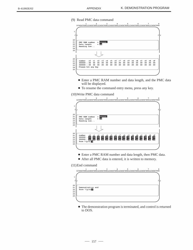
B–61992E/02 K. DEMONSTRATION PROGRAMAPPENDIX
157
(9) Read PMC data command1 2 3 4 5 6 7 8
12345678901234567890123456789012345678901234567890123456789012345678901234567890
1
202122232425
202122232425
number +0 +1 +2 +3 +4 +5 +6 +7 +8 +9 +A +B +C +D +E +F999999 : 99 99 99 99 99 99 99 99 99 99 99 99 99 99 99 99999999 : 99 99 99 99 99 99 99 99 99 99 99 99 99 99 99 99Please hit any key
PMC RAM number =999999Data length = 99Reading now...
� Enter a PMC RAM number and data length, and the PMC datawill be displayed.
� To resume the command entry menu, press any key.
(10)Write PMC data command1 2 3 4 5 6 7 8
12345678901234567890123456789012345678901234567890123456789012345678901234567890
1
202122232425
202122232425
PMC RAM number =999999Data length = 99Reading now...
number +0 +1 +2 +3 +4 +5 +6 +7 +8 +9 +A +B +C +D +E +F999999 : 99 99 99 99 99 99 99 99 99 99 99 99 99 99 99 99999999 : 99 99 99 99 99 99 99 99 99 99 99 99 99 99 99 99Sure ?(y/n) y
� Enter a PMC RAM number and data length, then PMC data.� After all PMC data is entered, it is written to memory.
(11)End command1 2 3 4 5 6 7 8
12345678901234567890123456789012345678901234567890123456789012345678901234567890
1
202122232425
Demonstration endSure ?(y/n) y
� The demonstration program is terminated, and control is returnedto DOS.
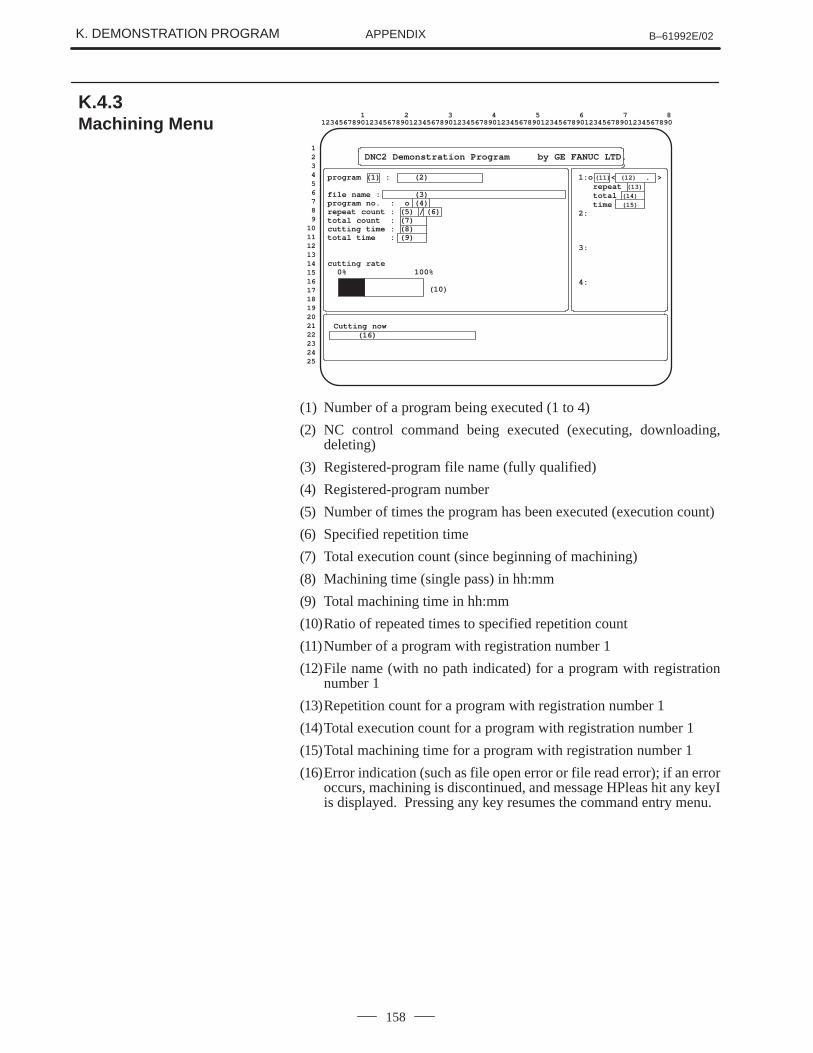
K. DEMONSTRATION PROGRAM B–61992E/02APPENDIX
158
program (1) : (2)
file name : (3)program no. : o (4)repeat count : (5) / (6)total count : (7)cutting time : (8)total time : (9)
cutting rate0% 100%
(10)
1:o (11) < (12) . >repeat (13)
total (14)
time (15)2:
3:
4:
Cutting now(16)
1 2 3 4 5 6 7 812345678901234567890123456789012345678901234567890123456789012345678901234567890
123456789
10111213141516171819202122232425
DNC2 Demonstration Program by GE FANUC LTD.
(1) Number of a program being executed (1 to 4)
(2) NC control command being executed (executing, downloading,deleting)
(3) Registered-program file name (fully qualified)
(4) Registered-program number
(5) Number of times the program has been executed (execution count)
(6) Specified repetition time
(7) Total execution count (since beginning of machining)
(8) Machining time (single pass) in hh:mm
(9) Total machining time in hh:mm
(10)Ratio of repeated times to specified repetition count
(11)Number of a program with registration number 1
(12)File name (with no path indicated) for a program with registrationnumber 1
(13)Repetition count for a program with registration number 1
(14)Total execution count for a program with registration number 1
(15)Total machining time for a program with registration number 1
(16)Error indication (such as file open error or file read error); if an erroroccurs, machining is discontinued, and message HPleas hit any keyIis displayed. Pressing any key resumes the command entry menu.
K.4.3Machining Menu
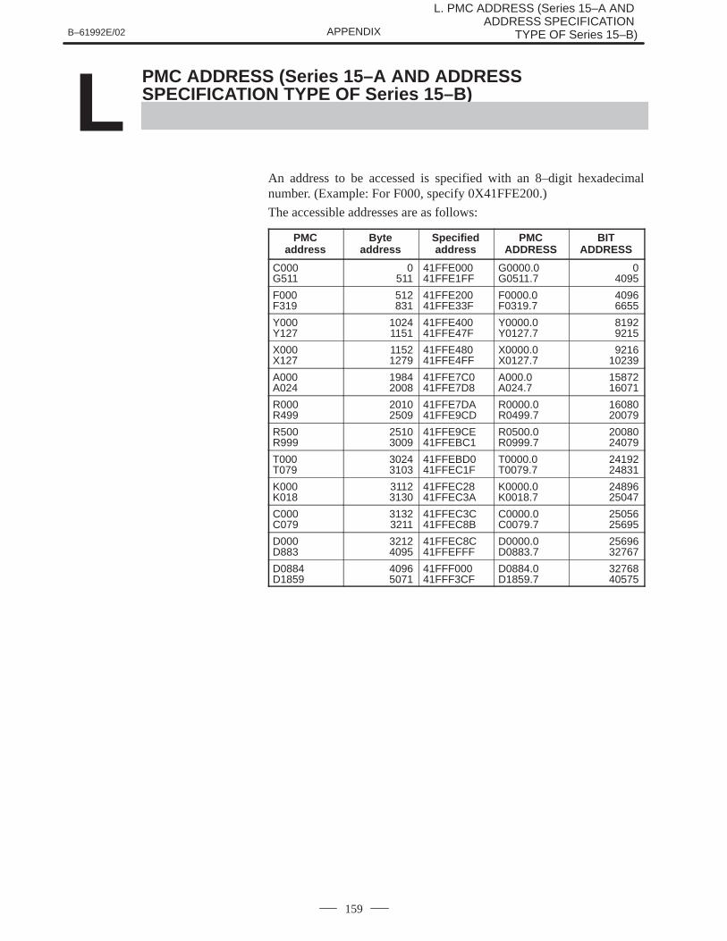
B–61992E/02
L. PMC ADDRESS (Series 15–A AND ADDRESS SPECIFICATION
TYPE OF Series 15–B)APPENDIX
159
L PMC ADDRESS (Series 15–A AND ADDRESSSPECIFICATION TYPE OF Series 15–B)
An address to be accessed is specified with an 8–digit hexadecimalnumber. (Example: For F000, specify 0X41FFE200.)
The accessible addresses are as follows:
PMCaddress
Byteaddress
Specifiedaddress
PMCADDRESS
BITADDRESS
C000G511
0511
41FFE00041FFE1FF
G0000.0G0511.7
04095
F000F319
512831
41FFE20041FFE33F
F0000.0F0319.7
40966655
Y000Y127
10241151
41FFE40041FFE47F
Y0000.0Y0127.7
81929215
X000X127
11521279
41FFE48041FFE4FF
X0000.0X0127.7
921610239
A000A024
19842008
41FFE7C041FFE7D8
A000.0A024.7
1587216071
R000R499
20102509
41FFE7DA41FFE9CD
R0000.0R0499.7
1608020079
R500R999
25103009
41FFE9CE41FFEBC1
R0500.0R0999.7
2008024079
T000T079
30243103
41FFEBD041FFEC1F
T0000.0T0079.7
2419224831
K000K018
31123130
41FFEC2841FFEC3A
K0000.0K0018.7
2489625047
C000C079
31323211
41FFEC3C41FFEC8B
C0000.0C0079.7
2505625695
D000D883
32124095
41FFEC8C41FFEFFF
D0000.0D0883.7
2569632767
D0884D1859
40965071
41FFF00041FFF3CF
D0884.0D1859.7
3276840575

M. DNC2 TOOL POST SELECTION M. (Series 15–TTB) B–61992E/02APPENDIX
160
MDNC2 TOOL POST SELECTION (Series 15–TTB)

B–61992E/02M. DNC2 TOOL POST SELECTION
(Series 15–TTB)APPENDIX
161
When tool–post–dependent data is input/output with the DNC2 functionof the Series 15–TTB, the target tool post can be selected.
This feature allows CNC data for tool posts 1 and 2 to be read and written.
M.1OUTLINE
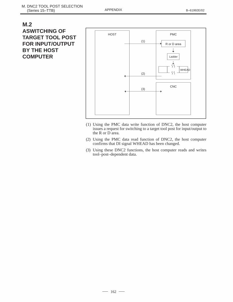
M. DNC2 TOOL POST SELECTION M. (Series 15–TTB) B–61992E/02APPENDIX
162
WHEAD
HOST PMC
CNC
(1)
(2)
(3)
R or D area
Ladder
(1) Using the PMC data write function of DNC2, the host computerissues a request for switching to a target tool post for input/output tothe R or D area.
(2) Using the PMC data read function of DNC2, the host computerconfirms that DI signal WHEAD has been changed.
(3) Using these DNC2 functions, the host computer reads and writestool–post–dependent data.
M.2ASWITCHING OFTARGET TOOL POSTFOR INPUT/OUTPUTBY THE HOSTCOMPUTER
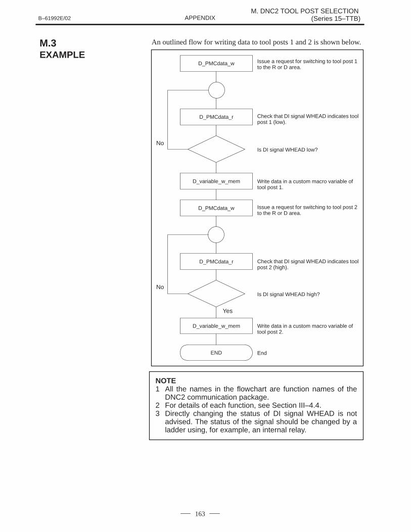
B–61992E/02M. DNC2 TOOL POST SELECTION
(Series 15–TTB)APPENDIX
163
An outlined flow for writing data to tool posts 1 and 2 is shown below.
D_PMCdata_r
D_PMCdata_w
D_variable_w_mem
D_PMCdata_w
D_PMCdata_r
D_variable_w_mem
END
No
No
Yes
Issue a request for switching to tool post 1to the R or D area.
Check that DI signal WHEAD indicates toolpost 1 (low).
Is DI signal WHEAD low?
Write data in a custom macro variable oftool post 1.
Issue a request for switching to tool post 2to the R or D area.
Check that DI signal WHEAD indicates toolpost 2 (high).
Is DI signal WHEAD high?
Write data in a custom macro variable oftool post 2.
End
NOTE1 All the names in the flowchart are function names of the
DNC2 communication package.2 For details of each function, see Section III–4.4.3 Directly changing the status of DI signal WHEAD is not
advised. The status of the signal should be changed by aladder using, for example, an internal relay.
M.3EXAMPLE
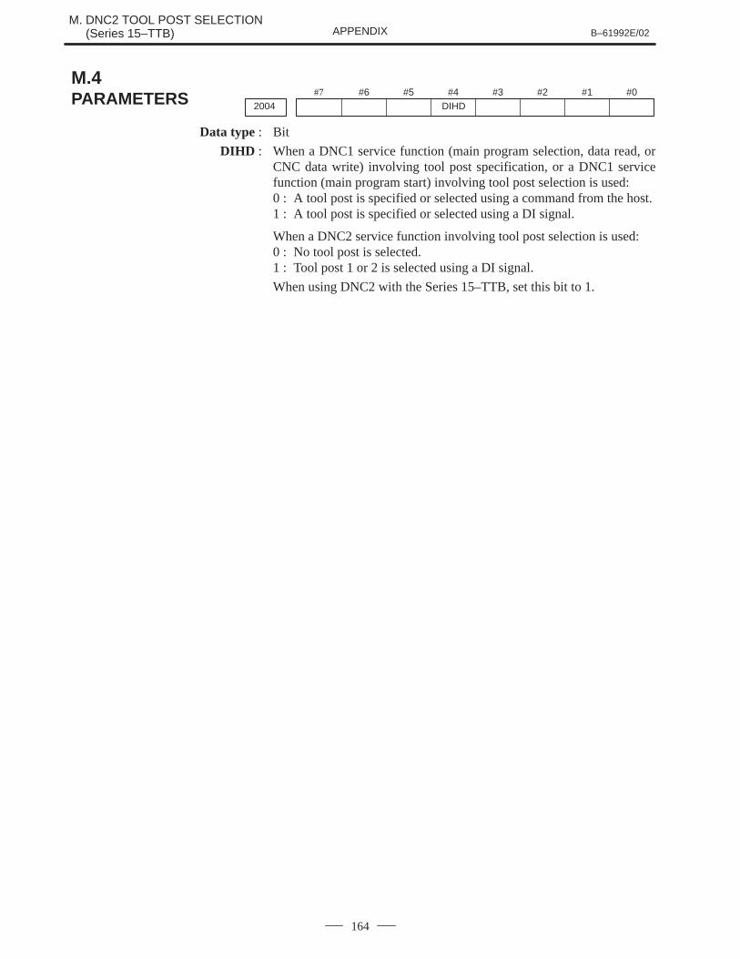
M. DNC2 TOOL POST SELECTION M. (Series 15–TTB) B–61992E/02APPENDIX
164
#7
2004#6 #5 #4
DIHD#3 #2 #1 #0
Data type : Bit
DIHD : When a DNC1 service function (main program selection, data read, orCNC data write) involving tool post specification, or a DNC1 servicefunction (main program start) involving tool post selection is used:0 : A tool post is specified or selected using a command from the host.1 : A tool post is specified or selected using a DI signal.
When a DNC2 service function involving tool post selection is used:0 : No tool post is selected.1 : Tool post 1 or 2 is selected using a DI signal.
When using DNC2 with the Series 15–TTB, set this bit to 1.
M.4PARAMETERS
B–61992E/02M. DNC2 TOOL POST SELECTION
(Series 15–TTB)APPENDIX
165
Tool post specification signal for NC window input/output WHEAD
[Type] Input signal
[Function] When a window function instruction or DNC2 functioninstruction is executed, this signal selects tool post 1 or 2.
[Operation] If this signal is low, executing a window function instructionor DNC2 function instruction causes input/output of the datarelated to tool post 1.
If this signal is high, executing a window functioninstruction or DNC2 function instruction causesinput/output of the data related to tool post 2.
It takes at least 8 ms for the WHEAD signal to be acceptedby the NC after the signal status is changed.
M.5CONNECTION

N. DNC2 SCREEN (Series 16/18) B–61992E/02APPENDIX
166
N DNC2 SCREEN (Series 16/18)
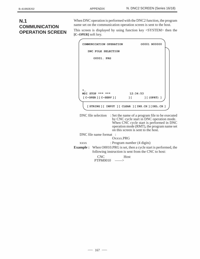
B–61992E/02 N. DNC2 SCREEN (Series 16/18)APPENDIX
167
When DNC operation is performed with the DNC2 function, the programname set on the communication operation screen is sent to the host.
This screen is displayed by using function key <SYSTEM> then the[C–OPER] soft key.
[ ][ ][ ][ ][ ]
[ ][ ][ ][ ][ ]
COMMUNICATION OPERATION O0001 N00000
DNC FOLE SELECTION
O0001. PRG
>_MDI STOP *** *** 12:34:53
C–OPER C–SERV (OPRT)
STRING INPUT CLEAR INS.CH DEL.CH
DNC file selection : Set the name of a program file to be executedby CNC cycle start in DNC operation mode.When CNC cycle start is performed in DNCoperation mode (RMT), the program name seton this screen is sent to the host.
DNC file name format :Oxxxx.PRG
xxxx : Program number (4 digits)Example : When O0010.PRG is set, then a cycle start is performed, the
following instruction is sent from the CNC to host:
CNC HostPTPM0010 ––––>
N.1COMMUNICATIONOPERATION SCREEN
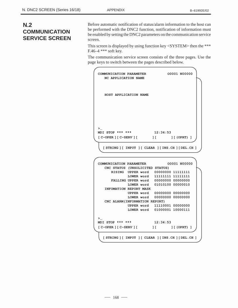
N. DNC2 SCREEN (Series 16/18) B–61992E/02APPENDIX
168
Before automatic notification of status/alarm information to the host canbe performed with the DNC2 function, notification of information mustbe enabled by setting the DNC2 parameters on the communication servicescreen.
This screen is displayed by using function key <SYSTEM> then the ***F.46–4 *** soft key.
The communication service screen consists of the three pages. Use thepage keys to switch between the pages described below.
COMMUNICATION PARAMETER O0001 N00000NC APPLICATION NAME
HOST APPLICATION NAME
>_MDI STOP *** *** 12:34:53
[ ][ ][ ][ ][ ]
[ ][ ][ ][ ][ ]C–OPER C–SERV (OPRT)
STRING INPUT CLEAR INS.CH DEL.CH
COMMUNICATION PARAMETER O0001 N00000CNC STATUS (UNSOLICITED STATUS)
RISING UPPER word 00000000 11111111LOWER word 11111111 11111111
FALLING UPPER word 00000000 00000000LOWER word 01010100 00000010
INFOMATION REPORT MASKUPPER word 00000000 00000000LOWER word 00000000 00000000
CNC ALARM(INFORMATION REPORT)UPPER word 11110001 00000000LOWER word 01000001 10000111
>_MDI STOP *** *** 12:34:53
[ ][ ][ ][ ][ ]
[ ][ ][ ][ ][ ]C–OPER C–SERV (OPRT)
STRING INPUT CLEAR INS.CH DEL.CH
N.2COMMUNICATIONSERVICE SCREEN
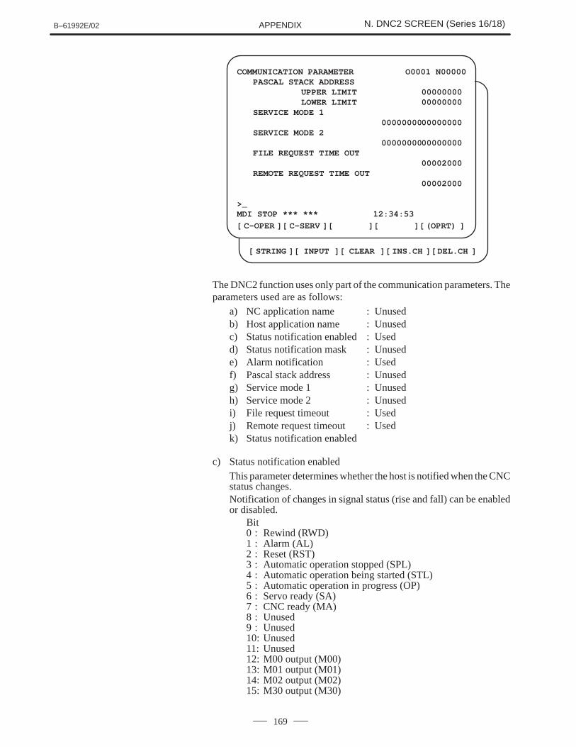
B–61992E/02 N. DNC2 SCREEN (Series 16/18)APPENDIX
169
COMMUNICATION PARAMETER O0001 N00000PASCAL STACK ADDRESS
UPPER LIMIT 00000000LOWER LIMIT 00000000
SERVICE MODE 10000000000000000
SERVICE MODE 20000000000000000
FILE REQUEST TIME OUT00002000
REMOTE REQUEST TIME OUT00002000
>_MDI STOP *** *** 12:34:53
[ ][ ][ ][ ][ ]
[ ][ ][ ][ ][ ]C–OPER C–SERV (OPRT)
STRING INPUT CLEAR INS.CH DEL.CH
The DNC2 function uses only part of the communication parameters. Theparameters used are as follows:
a) NC application name : Unusedb) Host application name : Unusedc) Status notification enabled : Usedd) Status notification mask : Unusede) Alarm notification : Usedf) Pascal stack address : Unusedg) Service mode 1 : Unusedh) Service mode 2 : Unusedi) File request timeout : Usedj) Remote request timeout : Usedk) Status notification enabled
c) Status notification enabledThis parameter determines whether the host is notified when the CNCstatus changes.Notification of changes in signal status (rise and fall) can be enabledor disabled.
Bit0 : Rewind (RWD)1 : Alarm (AL)2 : Reset (RST)3 : Automatic operation stopped (SPL)4 : Automatic operation being started (STL)5 : Automatic operation in progress (OP)6 : Servo ready (SA)7 : CNC ready (MA)8 : Unused9 : Unused10: Unused11: Unused12: M00 output (M00)13: M01 output (M01)14: M02 output (M02)15: M30 output (M30)
N. DNC2 SCREEN (Series 16/18) B–61992E/02APPENDIX
170
e) Alarm notification
This parameter sets whether to notify the host if an alarm is generatedin the CNC.
Bit0 : Foreground PS alarm1 : Background PS alarm2 : Overheat alarm3 : Undefined4 : Undefined5 : Parameter input enable alarm6 : Overtravel (OT) alarm7 : PMC error8 : External alarm9 : Undefined10: Severe PS alarm11: Undefined12: Servo alarm13: I/O alarm14: Undefined15: Battery alarm
i) File request timeout
This parameter sets the timeout value used for the time from when afile request is issued from the host to CNC until the CNC accepts therequest.If a timeout occurs, the CNC returns an error (M_NP 0XFDFF) to thehost.
NOTE1 A file request is a request for program downloading or
uploading.2 The parameter value is set as follows:
Unit : msRange : 16 ms to 9999.9984 s
(If 0 is set, 26 s is assumed.)
j) Remote request timeout
This parameter sets the timeout value used for the time from when aremote request is issued from the host to CNC until the CNC acceptsthe request.If a timeout occurs, the CNC returns an error (M_NP 0XFDFF) to thehost.
NOTE1 A remote request is a request from the host to the CNC
except program downloading and uploading requests.2 The parameter value is set as follows:
Unit : msRange : 16 ms to 9999.9984 s
(If 0 is set, 26 s is assumed.)
IndexB–61992E/02
i–1
[A]Acceleration/Deceleration Delay, 37
Alarm Messages, 129
Application Layer, 23
Application Layer Matrix, 127
[B]Blinking LED Indications, 134
[C]Code, 30
Command Entry, 154
Commands, 150
Communication Error Information, 103
Communication Mode, 13
Communication Operation Screen, 167
Communication Parameter Structure, 142
Communication Service Screen, 168
Communication Speed, 13
Compilation and Linking, 68
Compiling and Linking Programs, 147
Configuration, 7, 64
Configuration of Datagram Commands, 26
Connection, 165
Connector Specifications, 111
Continuation, 30
Current Program Number and Sequence Number, 38
[D]Data Link Layer, 18
Data Link Layer Matrix, 126
Data Link Protocol, 21
Data Type, 29
Datagram Protocol, 59
Datagram Syntax, 25
Deleting a Part Program, 33
Delimiter in the Data Section, 30
Demonstration Program, 145
Descriptions of Indication by LEDs (Series 15–A),134
Details, 73
Details of the Data Section, 31
Details of the Error Log File, 105
DNC2 screen (Series 16/18), 166
DNC2 Tool Post Selection (Series 15–TTB), 160
Downloading a Part Program, 31
[E]Error Codes, 102, 144
Error Codes Detailing Nefative Response, 131
Error Handling, 59
Error Log Information, 104
Establishing a Data Link, 21
Example, 163
Example of Using the Communication Program, 100
Executing a Program, 57
[F]FANUC Series 0 (A02B–0098–J055), 112
FANUC Series 0 (Upper Row: Series 0–TC, LowerRow: Series 0–MC), 117
FANUC Series 15–A, 113
FANUC Series 15–B and Series 16/18, 114
FANUC Series 16/18/21, 123
Files, 147
Format, 29
Free Area in Program Memory, 34
Function Specifications, 69
Functions, 24, 72
[I]Installation, 65
Installation Procedure, 67
Interrupt, 60
Interrupt Command, 59
Interrupt Procedure, 60
[L]Layers, 11
LED Indicators (Series 15–B), 137
Index B–61992E/02
i–2
Log Message Format, 139
Log Messages, 139
[M]Machine Interface Signals (For Series 15 only), 38
Machining Menu, 158
Machining Procedure, 152
Main Menu Format, 153
Maintenance, 133
MAP Log Messages, 139
Maximum Cable Length, 13
Menu Layout, 153
Message Format, 20
Modal Data and Corresponding Internal Codes, 141
[N]Negative Acknowledgment, 59
Nonblinking LED Indications, 135
Notation of the Datagram, 29
Notes, 71
[O]Operating Procedure, 151
Operator Messages, 53
Outline of Functions, 146
Overview of Operations, 150
[P]Parameters, 116, 164
Physical Interface, 13
Physical Layer, 12
PMC Address (Series 15–A and Address SpecificationType of Series 15–B), 159
Preparation, 147
[R]Reading a CNC Parameter, 39
Reading a System ID, 58
Reading a Tool Offset, 43
Reading a Tool Position, 35
Reading A/D Conversion Data, 49
Reading Alarm Information, 50
Reading an Actual Feedrate, 49
Reading Custom Macro Variables, 45
Reading Modal Information for Automatic Operation,48
Reading Pitch Error Compensation Data, 41
Reading PMC Data, 54
Reading Status Information, 51
Reading the Directory of Part Programs, 34
Reading Tool Life Management Data, 47
Receiving a Datagram, 22
Reset, 58
RS–232–C Interface, 14
RS–422 Interface, 16
[S]Selecting a Part Program, 57
Sending a Datagram, 21
Series 0, 130
Series 15, 120, 130
Service Functions Specified with Datagram Com-mands, 27
Servo Delay, 36
Setting the Communication Parameters, 148
Simple Error Log Browsing Function, 107
Starting and Exiting the Demonstration Program, 150
Supplied Programs, 66
Switching of Target Tool Post for Input/Output by theHost Computer, 162
Symbols, 29
Synchronous Method, 13
System Error Messages (Series 15–A), 136
System Error Messages (Series 15–B), 138
[T]Termination, 22
Transmission Characters, 20
Transmission Control Characters, 19
Troubleshooting, 139, 140

B–61992E/02 Index
i–3
[U]Uploading a Part Program, 32
Use, 70
[V]Values Returned by Functions, 103
[W]Writing a CNC Parameter, 40
Writing a Custom Macro Variable, 46
Writing a Tool Offset, 45
Writing Pitch Error Compensation, 42
Writing PMC Data, 55
Rev
isio
n R
ecor
d
FAN
UC ���
���������
��
(B
–619
92E
)
02O
ct.,
’97
�A
dditi
on o
f Ser
ies
16–A
/B/C
�A
dditi
on o
f Ser
ies
16i/1
8i/2
1i–A
01N
ov.,
’91
Edi
tion
Dat
eC
onte
nts
Edi
tion
Dat
eC
onte
nts

· No part of this manual may bereproduced in any form.
· All specifications and designsare subject to change withoutnotice.


