107
GE Fanuc Automation CIMPLICITY ® Monitoring and Control Products CIMPLICITY HMI Plant Edition Server Redundancy Operation Manual GFK-1353F July 2001 GE FANUC Parts
GE Fanuc Automation
CIMPLICITY® Monitoring and Control Products
CIMPLICITY HMI Plant Edition
Server RedundancyOperation Manual
GFK-1353F July 2001
GE FANUC Parts
ii CIMPLICITY HMI Server Redundancy Operation Manual–July 2001 GFK-1353F
GFL-005Following is a list of documentation icons:
Warning notices are used in this publication to emphasize that hazardous voltages, currents,temperatures, or other conditions that could cause personal injury exist in the equipment ormay be associated with its use.
In situations where inattention could cause either personal injury or damage to equipment, aWarning notice is used.
Caution provides information when careful attention must be taken in order to avoiddamaging results.
Important flags important information.
To do calls attention to a procedure.
Note calls attention to information that is especially significant to understanding andoperating the equipment.
Tip provides a suggestion.
Guide provides additional directions for selected topics.
This document is based on information available at the time of publication. While efforts have been made to be accurate,the information contained herein does not purport to cover all details or variations in hardware or software, nor to providefor every possible contingency in connection with installation, operation, or maintenance. Features may be describedherein which are not present in all hardware and software systems. GE Fanuc Automation assumes no obligation ofnotice to holders of this document with respect to changes subsequently made.
GE Fanuc Automation makes no representation of warranty, expressed, implied, or statutory with respect to, and assumesno responsibility for the accuracy, completeness, sufficiency, or usefulness of the information contained herein. Nowarranties of merchantability or fitness for purpose shall apply.
CIMPLICITY is a registered trademark of GE Fanuc Automation North America, Inc.Windows NT, Windows 2000 and Windows 98 are registered trademarks of Microsoft Corporation
This manual was produced using Doc-To-Help®, by WexTech Systems, Inc.Copyright 1998-2001 GE Fanuc Automation North America, Inc.
GFK-1353F iii
Preface
Content of this ManualChapter 1. Introducing Server Redundancy. Describes CIMPLICITY functionality and discusses
the various type of redundancy.
Chapter 2. Reviewing Server Redundancy. Reviews redundancy hardware requirements andprovides a redundancy operation overview.
Chapter 3. Configuring Server Redundancy. Describes the configuration procedures that supportCIMPLICITY Server Redundancy.
Chapter 4. Using the Redundancy Object. Describes the redundancy object.
Chapter 5. Recovery Procedures. Describes starting and stopping redundant projects and how toresett the primary server after recovery..
Chapter 6. Using Cabling Redundancy. Provides cabling redundancy configuration procedures.
Appendix A. Using Supported Communication Interfaces. Discusses the communication interfacessupported by CIMPLICITY Server Redundancy.
Appendix B. Configuration Parameters. Documents the configuration parameters needed forCIMPLICITY Server Redundancy.
Appendix C. Computer Cabling Redundancy Status Log Messages. Lists the Status Log messagesgenerated by the Computer Cabling Redundancy option.
Appendix D. Troubleshooting Database Merging. Lists issues and solutions for database merging.
GE FANUC Parts

iv CIMPLICITY HMI Server Redundancy Operation Manual–July 2001 GFK-1353F
Related PublicationsFor more information, refer to these publications:
CIMPLICITY HMI Plant Edition Base System User's Manual (GFK-1180). This book describes allthe basic features of the CIMPLICITY HMI product.
CIMPLICITY HMI Plant Edition Device Communications Manual (GFK-1181). This bookdocuments all the device communication enablers for the CIMPLICITY HMI product.
GFK-1353F Contents-v
Contents
Introducing Server Redundancy 1-1Welcome to CIMPLICITY Server Redundancy..................................................................... 1-1Levels of Redundancy ............................................................................................................ 1-2
PLC Redundancy ..................................................................................................... 1-3Cabling Redundancy ................................................................................................ 1-3Server Redundancy .................................................................................................. 1-4Computer Network Redundancy.............................................................................. 1-4
Redundancy Types Supported by CIMPLICITY ................................................................... 1-5Server Redundancy .................................................................................................. 1-5Computer Cabling Redundancy ............................................................................... 1-5
Reviewing Server Redundancy 2-1Before You Start .................................................................................................................... 2-1
Reviewing Hardware Requirements......................................................................... 2-1Reviewing Application Requirements...................................................................... 2-4
Server Redundancy Overview................................................................................................ 2-6Automatic Redundancy Operation Overview......................................................................... 2-7
Summarizing Server Redundancy Operation ........................................................... 2-7Understanding Automatic Server Redundancy Limitations ..................................... 2-8Reviewing Server Redundancy Data Collection ...................................................... 2-9Reviewing Setpoint Use in Server Redundancy..................................................... 2-12Reviewing Database Logging in Server Redundancy ............................................ 2-12Defining Alarm Management Behavior in Server Redundancy ............................. 2-14Defining User Registration in Server Redundancy ................................................ 2-14Defining CimView Behavior in Server Redundancy ............................................. 2-14Defining Failover Period in a Server ..................................................................... 2-14
Manual Redundancy Overview ............................................................................................ 2-15Adhering to Point Requirements for Manual Server Redundancy ......................... 2-17Transferring Point Management Manually (Including Data Collection)................ 2-17Forcing Manual Project Transfer ........................................................................... 2-19
Configuring Server Redundancy 3-1About Redundancy Configuration Procedures ....................................................................... 3-1Base System Configuration .................................................................................................... 3-1
1. Configure a Project for Server Redundancy......................................................... 3-22. Configure Networks for Server Redundancy ....................................................... 3-33. Configure Device Communications for Server Redundancy................................ 3-54. Configure Global Points for Server Redundancies .............................................. 3-5
Database Logging Configuration............................................................................................ 3-6Configuring Windows ODBC Data Source Administrator ...................................... 3-6Configuring the Logging Properties Dialog Box ................................................... 3-15
GE FANUC Parts
Contents-vi CIMPLICITY HMI Server Redundancy Operation Manual–July 2001 GFK-1353F
Using the Redundancy Object 4-1About the Redundancy Object................................................................................................ 4-1
Reviewing the Redundancy Object Components ..................................................... 4-2Redundancy Object Use ......................................................................................................... 4-4
Step 1. Display the Redundancy CimView Screen................................................... 4-4Step 2. Monitor the Servers through the Redundancy Screen .................................. 4-5Step 3. Switch the Master Role between Redundant Computers.............................. 4-6
Recovery Procedures 5-1Normal Operating Procedures ................................................................................................ 5-1
Starting and Stopping Redundant CIMPLICITY Projects ....................................... 5-1Starting the Project from the Secondary Server ....................................................... 5-3Configuring the Project to Start at Boot................................................................... 5-4
Primary Server Failure ........................................................................................................... 5-5Understanding System Operation during Failover ................................................... 5-5Detecting the Cause of Primary Server Failure ........................................................ 5-6Resetting the Primary Server after Recovery ........................................................... 5-7Re-synchronizing Database Logging Files ............................................................... 5-8
Failure Exceptions for Automatic Server Redundancy......................................................... 5-10
Using Cabling Redundancy 6-1About Computer Cabling Redundancy................................................................................... 6-1
Understanding Operation Rules ............................................................................... 6-2Reviewing Limitations of Computer Cabling Redundancy ...................................... 6-2Reviewing Hardware Requirements for Cabling Redundancy ................................. 6-3
Supported Network Configurations for Cabling Redundancy ................................................ 6-4Cabling Redundancy Configuration Procedures..................................................................... 6-4
Entering IP Addresses for Cabling Redundancy ...................................................... 6-4Configuring Failover Rate for Cabling Redundancy................................................ 6-5Generating Diagnostic Output for Cabling Redundancy.......................................... 6-5Using TCP/IP Port for Cabling Redundancy............................................................ 6-6
Monitoring Network and Socket Status 7-1Computer Cabling Redundancy Monitoring........................................................................... 7-1IP Status API .......................................................................................................................... 7-2IP Status API Functions.......................................................................................................... 7-3Socket Status API................................................................................................................... 7-6Socket Status API Functions .................................................................................................. 7-8
Appendix A - Using Supported Communication Interfaces A-1About Supported Communication Interfaces......................................................................... A-1Series 90 TCP/IP Communications ....................................................................................... A-2Series 90 TCP/IP Redundancy Communications .................................................................. A-2CCM2 Communications ........................................................................................................ A-3Genius Communications........................................................................................................ A-3SNPX Communications......................................................................................................... A-4Allen-Bradley Communications ............................................................................................ A-4Allen-Bradley Data Highway Plus Communications............................................................. A-5APPLICOM Communications............................................................................................... A-5DDE Client Communications ................................................................................................ A-5Modbus Plus Communications .............................................................................................. A-6
GFK-1353F Contents Contents-vii
Modbus RTU Communications............................................................................................. A-7Modbus TCP/IP .................................................................................................................... A-8OPC Client ............................................................................................................................ A-8Point Bridge .......................................................................................................................... A-8
Appendix B - Configuration Parameters B-1About Server Redundancy Configuration Parameters ............................................................B-1Failover Rate Configuration...................................................................................................B-1User Registration Synchronization.........................................................................................B-2Slave Startup ..........................................................................................................................B-2
Appendix C - Computer Cabling Redundancy Status Log Messages C-1Error Messages.......................................................................................................................C-1
Appendix D - Troubleshooting Database Merging D-1Problems and Solutions......................................................................................................... D-1
Index i
GE FANUC Parts

GFK-1353F 1-1
Introducing Server Redundancy
Welcome to CIMPLICITY Server RedundancyCongratulations, you’ve chosen to use CIMPLICTY Server Redundancy as part of yourMission Critical Application. You should completely review and understand this manualbefore getting started with your application.
The topics (chapters) in this manual include:
� Server redundancy overview, including.� Hardware requirements� Application requirements� Automatic and manual redundancy
� Redundancy configuration.� The Redundancy object.� Recovery procedures.� Cabling redundancy.� Network and socket status.� Supported communication interfaces.� Configuration parameters.� Status log messages.� Troubleshooting database merging.
GE FANUC Parts

1-2 CIMPLICITY HMI Server Redundancy Operation Manual–July 2001 GFK-1353F
Levels of RedundancyThe principle of redundancy in automated systems provides for switchover offunctionality to a backup component in case of failure of a primary component. Theswitchover is considered automatic if no operator intervention is required. Redundancyapplies to both hardware and software, and implies minimal loss of continuity during thetransfer of control between primary (active) and redundant (backup) components.Redundant systems reduce single points of failure, preventing loss of functionality.
For cell control systems, the major levels of redundancy include:
� PLC.� Cabling (PLC LAN or serial connections to server).� Computer server redundancy.� Computer networks.
Each level of redundancy provides a failover system that allows continuous systemactivity with minimal loss of data. The following sections briefly describe each level.
GFK-1353F Introducing Server Redundancy 1-3
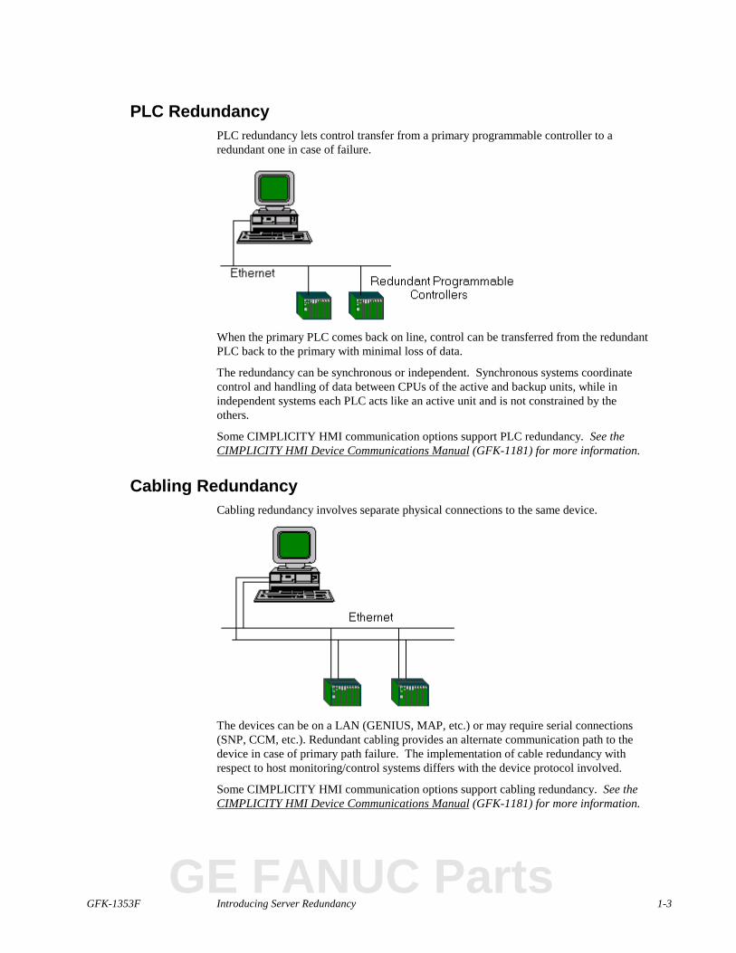
PLC RedundancyPLC redundancy lets control transfer from a primary programmable controller to aredundant one in case of failure.
When the primary PLC comes back on line, control can be transferred from the redundantPLC back to the primary with minimal loss of data.
The redundancy can be synchronous or independent. Synchronous systems coordinatecontrol and handling of data between CPUs of the active and backup units, while inindependent systems each PLC acts like an active unit and is not constrained by theothers.
Some CIMPLICITY HMI communication options support PLC redundancy. See theCIMPLICITY HMI Device Communications Manual (GFK-1181) for more information.
Cabling RedundancyCabling redundancy involves separate physical connections to the same device.
The devices can be on a LAN (GENIUS, MAP, etc.) or may require serial connections(SNP, CCM, etc.). Redundant cabling provides an alternate communication path to thedevice in case of primary path failure. The implementation of cable redundancy withrespect to host monitoring/control systems differs with the device protocol involved.
Some CIMPLICITY HMI communication options support cabling redundancy. See theCIMPLICITY HMI Device Communications Manual (GFK-1181) for more information.
GE FANUC Parts
1-4 CIMPLICITY HMI Server Redundancy Operation Manual–July 2001 GFK-1353F
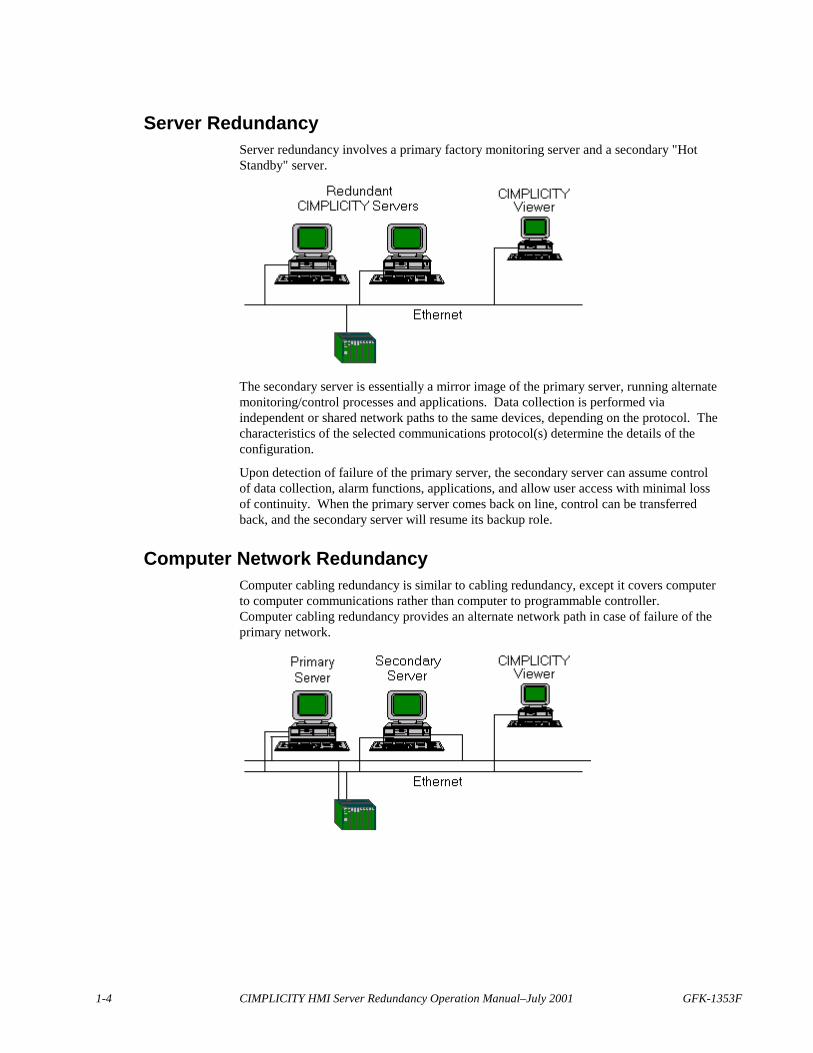
Server RedundancyServer redundancy involves a primary factory monitoring server and a secondary "HotStandby" server.
The secondary server is essentially a mirror image of the primary server, running alternatemonitoring/control processes and applications. Data collection is performed viaindependent or shared network paths to the same devices, depending on the protocol. Thecharacteristics of the selected communications protocol(s) determine the details of theconfiguration.
Upon detection of failure of the primary server, the secondary server can assume controlof data collection, alarm functions, applications, and allow user access with minimal lossof continuity. When the primary server comes back on line, control can be transferredback, and the secondary server will resume its backup role.
Computer Network RedundancyComputer cabling redundancy is similar to cabling redundancy, except it covers computerto computer communications rather than computer to programmable controller.Computer cabling redundancy provides an alternate network path in case of failure of theprimary network.

GFK-1353F Introducing Server Redundancy 1-5
Redundancy Types Supported by CIMPLICITYCIMPLICITY HMI software supports two types of redundancy:
� Server Redundancy� Computer Cabling Redundancy
Server RedundancyServer Redundancy is fully integrated with CIMPLICITY HMI software’s base systemfunctionality, enhancing its already powerful monitoring capability in a full range ofcomputer-integrated manufacturing environments.
Computer Cabling RedundancyCIMPLICITY Computer Cabling Redundancy provides network redundancy betweenCIMPLICITY Servers and Viewers. The CIMPLICITY Ethernet traffic travels overboth networks in parallel, thus the loss of a single network causes no loss ofcommunications.
GE FANUC Parts


GFK-1353F 2-1
Reviewing Server Redundancy
Before You StartSimply enabling server redundancy for your project provides you with a wealth ofredundancy features. However, server redundancy is only a part of your system. Theother key parts of your system are your Project, PLCs and the communications network.Combined together these pieces form a mission critical application. Therefore, theapplication is only as robust as its weakest link. While server redundancy provides manybuilt in features, it cannot repair a faulty network or fix incorrectly written logic. Serverredundancy depends on you, the Control Engineer to build a robust environment toenable server redundancy to perform its job.
This section provides an overview of the decisions you need to make while designingyour mission critical application.
Reviewing Hardware RequirementsBecause the secondary server in a redundant pair will be set up to run exactly the samefunctions (except for configuration functions) as the primary server, the secondary serverin a redundant pair must be identical to the primary server; that is, the disk, memory, andinput/output peripherals should be identical.
Cabling to devices may place the primary and redundant servers on the same or differentcables. The type of cabling used will depend on the requirements of the device.Communications interface software supported by CIMPLICITY Server Redundancyattempts to minimize network traffic to and from the secondary server.
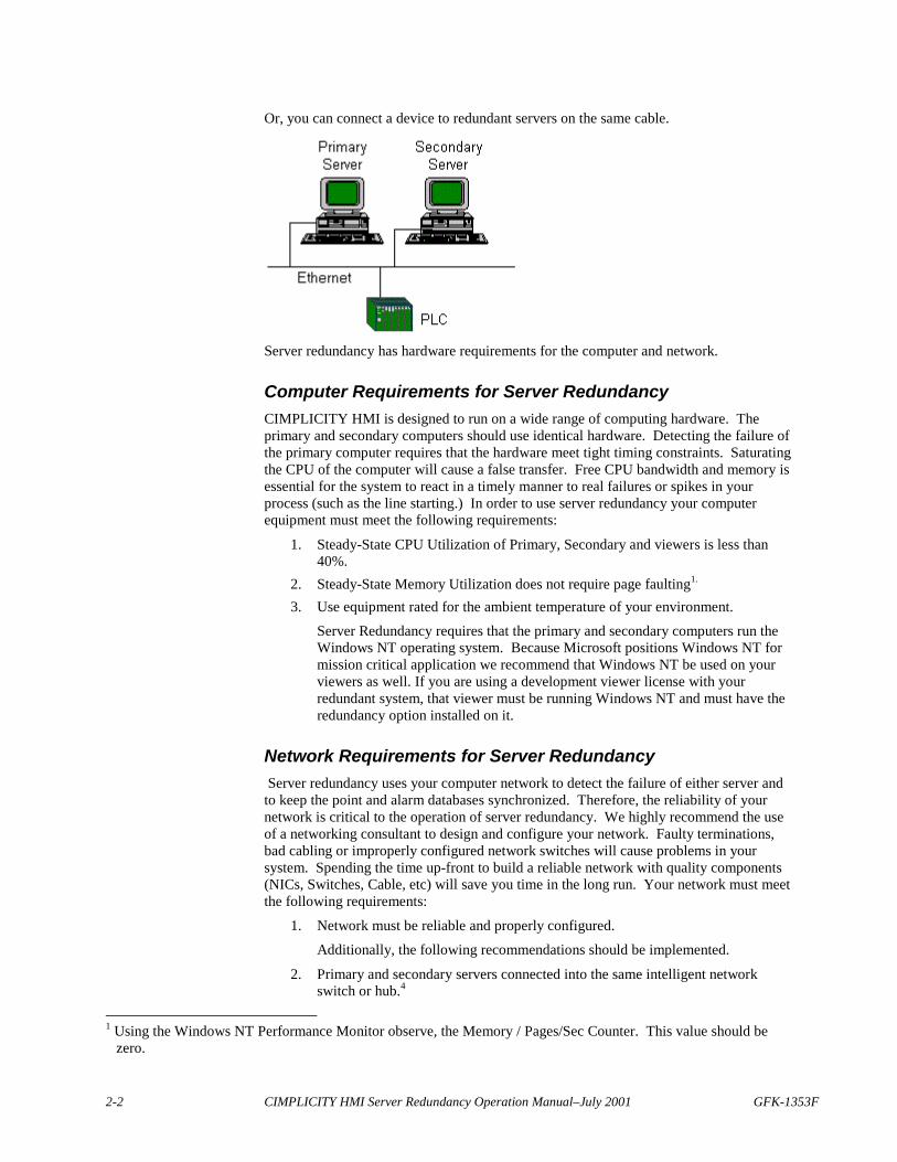
You can connect a device to redundant servers via different cables.
GE FANUC Parts
2-2 CIMPLICITY HMI Server Redundancy Operation Manual–July 2001 GFK-1353F
Or, you can connect a device to redundant servers on the same cable.
Server redundancy has hardware requirements for the computer and network.
Computer Requirements for Server RedundancyCIMPLICITY HMI is designed to run on a wide range of computing hardware. Theprimary and secondary computers should use identical hardware. Detecting the failure ofthe primary computer requires that the hardware meet tight timing constraints. Saturatingthe CPU of the computer will cause a false transfer. Free CPU bandwidth and memory isessential for the system to react in a timely manner to real failures or spikes in yourprocess (such as the line starting.) In order to use server redundancy your computerequipment must meet the following requirements:
1. Steady-State CPU Utilization of Primary, Secondary and viewers is less than40%.
2. Steady-State Memory Utilization does not require page faulting1.
3. Use equipment rated for the ambient temperature of your environment.
Server Redundancy requires that the primary and secondary computers run theWindows NT operating system. Because Microsoft positions Windows NT formission critical application we recommend that Windows NT be used on yourviewers as well. If you are using a development viewer license with yourredundant system, that viewer must be running Windows NT and must have theredundancy option installed on it.
Network Requirements for Server Redundancy Server redundancy uses your computer network to detect the failure of either server andto keep the point and alarm databases synchronized. Therefore, the reliability of yournetwork is critical to the operation of server redundancy. We highly recommend the useof a networking consultant to design and configure your network. Faulty terminations,bad cabling or improperly configured network switches will cause problems in yoursystem. Spending the time up-front to build a reliable network with quality components(NICs, Switches, Cable, etc) will save you time in the long run. Your network must meetthe following requirements:
1. Network must be reliable and properly configured.
Additionally, the following recommendations should be implemented.
2. Primary and secondary servers connected into the same intelligent networkswitch or hub.4
1 Using the Windows NT Performance Monitor observe, the Memory / Pages/Sec Counter. This value should be
zero.

GFK-1353F Reviewing Server Redundancy 2-3
.3. Steady-State Memory Utilization should be less than 10%.5
4. Ping times between primary and secondary servers must be less than 10ms,between viewers and servers less than 30ms.
5. Use equipment rated for the ambient temperature of your environment.6. The servers should not use DHCP unless the leases never expire.
Additionally, the following recommendations should be implemented.
1. Primary and secondary servers connected into the same intelligent networkswitch or hub.6
2. Consider using 100mbs Ethernet between the primary and secondary computers.3. Consider isolating Server to PLC Traffic on a private network segment.
Server redundancy requires a reliable network, if network reliability is an issue youshould consider implementing cabling redundancy between the servers and viewers.
4 A large volume of network traffic occurs between the primary and secondary computers. These two computers
should be plugged into a network switch that will isolate the inter-server communications from the rest of thenetwork.
5 Using the Windows NT Performance Monitor observe, the Memory / Pages/Sec Counter. This value should bezero.
6 A large volume of network traffic occurs between the primary and secondary computers. These two computersshould be plugged into a network switch that will isolate the inter-server communications from the rest of thenetwork.
GE FANUC Parts
2-4 CIMPLICITY HMI Server Redundancy Operation Manual–July 2001 GFK-1353F
Reviewing Application RequirementsServer redundancy provides automatic synchronization of Point and Alarm Databases.Server redundancy provides automatic switchover of CimView application using Pointsand Alarms. Before you start building your application you should review the section inthis manual entitled “Limitation of Server Redundancy”, to verify that the features ofCIMPLICITY that you intend on using are supported in server redundancy.:.
CIMPLICITY will run your application as you design it. CIMPLICITY cannotautomatically fix your project if you design it incorrectly. Therefore, it is important thatyou design your project to be mission critical from the ground up. Also, it is imperativethat you test your application in a server redundant environment with viewers during thedevelopment stage. Only with a properly configured project can you switch on serverredundancy and have it work flawlessly.
We at GE Fanuc have designed many redundant systems using CIMPLICITY. Weunderstand the methodology and design techniques needed to build a robust system.Therefore, we do recommend contacting your salesperson to obtain several days ofdesign consultation before you start your first project, and several days of on-site supportduring deployment.
Scripting Requirements for Server RedundancyThe single biggest issue in building a server redundancy system is youruser defined scripts. During failover, point values may be unavailable for a shorttime. Scripts must be written to properly handle these intermittent periods and to exitcleanly. Scripts that depend on cleanly exiting must be coded to trap the errors that canoccur when a point goes unavailable. You must test your scripts during fail over to verifythey operate correctly.
Use of Primary / Secondary ComputersThe purpose of your primary and secondary computers is to read and process data fromyour devices, distribute it to viewers, and to remain synchronized. They need availableCPU bandwidth to handle exception conditions in your process. If you have viewers inyour system, the primary and secondary servers should not run user interface applicationssuch as CimView. The secondary server is not a “spare” computer to be used to performother chores like word processing, etc. It is a hot backup, dedicated to providingredundancy for your mission critical application.
Important: The primary computer must have a mapped drive to the secondarycomputer. It is through this mapped drive that a qualified user (a user with administrativeprivileges) can start and stop the slave.
Database Logging RequirementsIf you are planning on using database logging, you should certainly read the informationin this document on how to use logging within a server redundancy project. Additionally,in a mission critical application, the use of Microsoft Access as a database is notsupported. Instead, Microsoft SQL Server, Oracle, or other supported database servermust be used. If you plan on logging a large volume of data you may want to considerlocating the database servers on separate computers within the same LAN / switch as theprimary and secondary. Remember the total CPU utilization, including the databaseserver, must be less than 40%.

GFK-1353F Reviewing Server Redundancy 2-5
Network Configuration RequirementsIn addition to having a solid physical network, server redundancy requires specificnetwork software configuration to be performed on every computer in the system. Sincespecific configuration is required on every computer you cannot just “plug” anotherviewer into the network and expect it to work. The network configuration must beupdated on the viewer and related computers.
Time Synchronization RequirementsThe times on the Primary and Secondary computer must be synchronized. Additionally,if using trending on viewer computers, the times on the viewers must be synchronizedwith the servers. It is your responsibility to ensure that the computer times aresynchronized. There are a variety of commercial products available to maintain timesynchronization between computers. If you choose to automatically synchronize yourclocks do so at any time other than midnight.
GE FANUC Parts
2-6 CIMPLICITY HMI Server Redundancy Operation Manual–July 2001 GFK-1353F
Server Redundancy OverviewCIMPLICITY HMI software’s Base System Functionality fully integrates AutomaticServer Redundancy. This functionality transfers control from a primary to a secondaryserver when the primary goes down and, as a result, the connection between the primaryand secondary is severed.
Redundant features are integrated into Point Management, Device Communications, UserRegistration and Alarm Management. The focus of redundancy in CIMPLICITY HMIsoftware centers on:
� Data collection� Applications driven by these data� Alarms� Users accessing these applications
CIMPLICITY HMI also offers the capability for manual redundancy. Manual ServerRedundancy lets control be transferred from a primary to a secondary server, even if theprimary is active and the two servers are connected. Transfer capability includes:
� Point management, including data collection� Entire project control
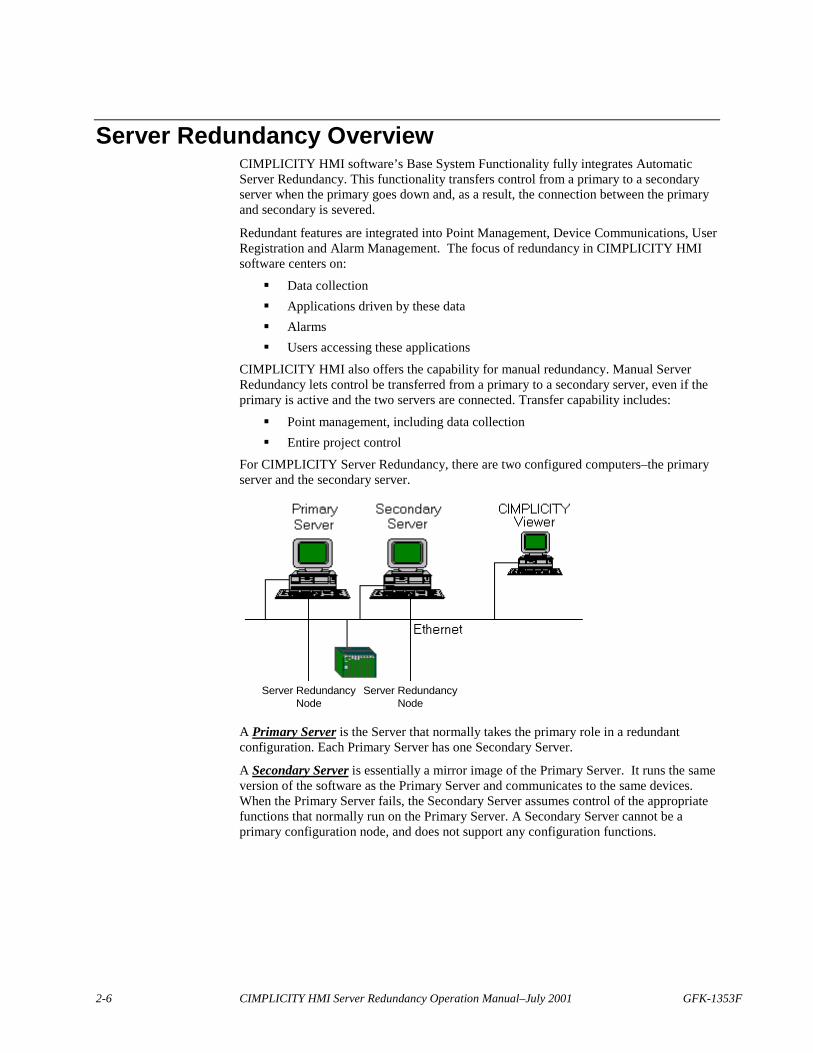
For CIMPLICITY Server Redundancy, there are two configured computers–the primaryserver and the secondary server.
Server RedundancyNode
Server RedundancyNode
A Primary Server is the Server that normally takes the primary role in a redundantconfiguration. Each Primary Server has one Secondary Server.
A Secondary Server is essentially a mirror image of the Primary Server. It runs the sameversion of the software as the Primary Server and communicates to the same devices.When the Primary Server fails, the Secondary Server assumes control of the appropriatefunctions that normally run on the Primary Server. A Secondary Server cannot be aprimary configuration node, and does not support any configuration functions.
GFK-1353F Reviewing Server Redundancy 2-7
Automatic Redundancy Operation OverviewThis section will provide a general overview of how server redundancy operates so youcan accurately design your mission critical application.
Server Redundancy is configured from within the Workbench on the primary computer.The primary computer has a mapped drive to a secondary computer. The Workbench willautomatically distribute the configuration data to the secondary and can control startup /shutdown of the pair.
Summarizing Server Redundancy Operation
Important: A user must be logged on with administrative privileges when mapping thedrive the slave will be running on. If the user does not have administrative privileges theproject will not start on the slave.
In a normal state:
� The primary is in control or is the active server.� The secondary is the standby server.� The primary keeps the secondary Alarm, Point and User information
synchronized.� Viewers collect data from the primary computer.
When the primary fails:
� The primary is off line.� The secondary becomes the active server.� Viewers collect data from the secondary computer.
When the project on the primary is restarted:
� The primary obtains Alarm and User information from the secondary andautomatically takes over these functions.
� The secondary continues to provide and collect point data for the viewers andthe primary for synchronization.
After a system manager resets the primary:
� The primary collects point data and takes over point management as well as allother project functions.
� The secondary returns to standby mode.
See “Resetting the Primary Server after Recovery” in the “Recovery Procedures”chapter of this manual for more information about restarting the primary server.
GE FANUC Parts
2-8 CIMPLICITY HMI Server Redundancy Operation Manual–July 2001 GFK-1353F
Understanding Automatic Server Redundancy LimitationsThere are some limitations to automatic server redundancy functionality and failure.Manual server redundancy is a solution for some of these limitations.
Limitations on Automatic Server Redundancy FunctionalityThe following limitations apply for automatic Server Redundancy:
1. You may not use the:� Multiple Projects feature on the redundant servers� Enterprise Server capability
2. The following are not supported:� Dynamic updates for the Event Manager� Recipes� SPC� Tracker
3. Viewers have the following limitations:� Fail over is not supported for Viewers in the following cases:
� BCEUI displays� CimView screens with embedded Recipe objects� CimView screens with embedded SPC objects� CimView screens with embedded Historical Data Analyzer objects� Computers that use a Remote Access Server (RAS) or a Wide Area
Network (WAN) connection� Show Users displays
� Viewers must have local copies of CimView screens to operate followingfail over.
4. The primary server in redundancy must be a development server. (This is alicensing requirement.)
5. If you are accessing at logged data when the primary server fails, you will haveto switch to the secondary data source to continue accessing the logged data for:� Trending� SPC� Historical Data Analyzer
6. For Trending, point-buffering information is lost on fail over.7. Configuration changes that cannot be made dynamically require the entire
project to be shut down on both computers then be updated and restarted.8. Dynamic configuration changes can only be made when both computers are
running.9. During fail over, device values are not read and setpoints are not written.
GFK-1353F Reviewing Server Redundancy 2-9
Limitations on Automatic Server Redundancy FailureRecoveryCIMPLICITY Server Redundancy will not cover the following failures. Applicationdevelopment for manual server redundancy can frequently circumvent these limitations:
� Loss of data due to failure of a single component involved in data collection.
If a cable or LAN interface fails, CIMPLICITY software detects the problem,but it will not automatically start collecting data on the secondary server. Underthese circumstances, a user may choose to shut down the primary server to allowthe secondary server to take over.
� Loss of the communications link between CIMPLICITY primary and secondaryservers while the primary server is still running.
If the link is lost, both servers will act as the primary server. The secondaryserver will need to be shut down, and the network repaired. CIMPLICITYsoftware can then be restarted on the secondary server.
Reviewing Server Redundancy Data CollectionA runtime Point Management database that holds current data values ismaintained on the primary server and duplicated on the secondary server.
The primary Point Manager:
1. Processes point updates from:� Device Communication and the Virtual Point Process on the primary server� All manual and automatic control functions
2. Sends updates to the secondary Point Manager.
If device communications processes are running on the primary server, the correspondingprocesses also run on the secondary server.
While the primary server is the master, the device communication modules on thesecondary server operate in standby mode to minimize the impact of redundant datacollection on the communications LAN or the programmable controller.
When the primary server terminates, the:
1. Secondary Point Manager automatically begins receiving its updates from� The Device Communications and Virtual Point Process on the secondary
server� All manual and automatic control functions.
2. Device Communications on the secondary server:� Establishes full communications with the devices and scans all point values.� Reports all point data to the Point Manager.
GE FANUC Parts
2-10 CIMPLICITY HMI Server Redundancy Operation Manual–July 2001 GFK-1353F
1
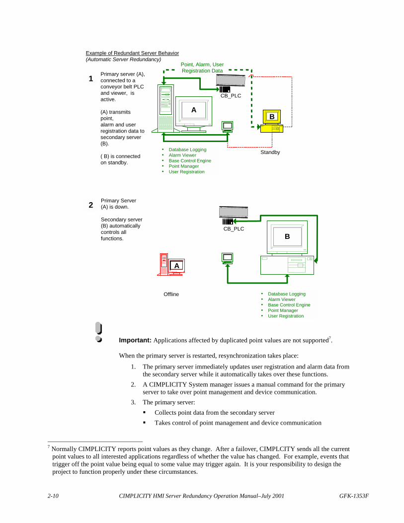
Example of Redundant Server Behavior(Automatic Server Redundancy)
Primary server (A),connected to aconveyor belt PLCand viewer, isactive.
(A) transmitspoint,alarm and userregistration data tosecondary server(B).
( B) is connectedon standby.
2 Primary Server(A) is down.
Secondary server(B) automaticallycontrols allfunctions.
� Database Logging� Alarm Viewer� Base Control Engine� Point Manager� User Registration
CB_PLCB
Offline
CB_PLC
� Database Logging� Alarm Viewer� Base Control Engine� Point Manager� User Registration
Standby
BA
Point, Alarm, UserRegistration Data
A
Important: Applications affected by duplicated point values are not supported7.
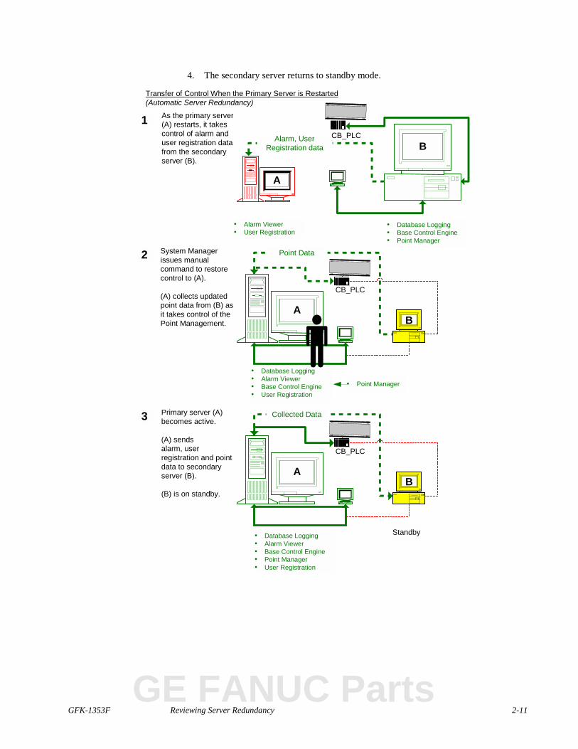
When the primary server is restarted, resynchronization takes place:
1. The primary server immediately updates user registration and alarm data fromthe secondary server while it automatically takes over these functions.
2. A CIMPLICITY System manager issues a manual command for the primaryserver to take over point management and device communication.
3. The primary server:� Collects point data from the secondary server� Takes control of point management and device communication
7 Normally CIMPLICITY reports point values as they change. After a failover, CIMPLCITY sends all the current
point values to all interested applications regardless of whether the value has changed. For example, events thattrigger off the point value being equal to some value may trigger again. It is your responsibility to design theproject to function properly under these circumstances.
GFK-1353F Reviewing Server Redundancy 2-11
4. The secondary server returns to standby mode.
1
Transfer of Control When the Primary Server is Restarted(Automatic Server Redundancy)
As the primary server(A) restarts, it takescontrol of alarm anduser registration datafrom the secondaryserver (B).
2 System Managerissues manualcommand to restorecontrol to (A).
(A) collects updatedpoint data from (B) asit takes control of thePoint Management.
� Database Logging� Base Control Engine� Point Manager
CB_PLCB
A
Alarm, UserRegistration data
� Alarm Viewer� User Registration
3 Primary server (A)becomes active.
(A) sendsalarm, userregistration and pointdata to secondaryserver (B).
(B) is on standby.
CB_PLC
Standby
BA
Collected Data
CB_PLC
� Database Logging� Alarm Viewer� Base Control Engine� User Registration
BA
Point Data
� Database Logging� Alarm Viewer� Base Control Engine� Point Manager� User Registration
� Point Manager
GE FANUC Parts
2-12 CIMPLICITY HMI Server Redundancy Operation Manual–July 2001 GFK-1353F
Reviewing Setpoint Use in Server RedundancyUsers can make setpoint requests on either the primary or secondary server via:
� Point Control Panel� CimView� Automatic Control Functions (Event Manager, Custom Programs)
While the primary server is running, all setpoints from the secondary server except thosefrom the Automatic Control Function will be routed to the primary computer. Allsetpoint originating from Automatic Control Functions on the secondary will bediscarded when the primary is in control.
Let’s consider the case of the Event Manager. The Event Manager runs on both theprimary and secondary computers. Events are triggered on both the primary andsecondary computers. All setpoint requests invoked from the action or script tied to theevent will be ignored on the slave computer. In other words, your scripts execute intandem on both computers, but the output to the points is processed only on the mastercomputer.
A Custom Program would be a PTMAP API program written by you that executes as aresident process within CIMPLICITY. Setpoints originating from this program will workthe same as the Event Manager.
Reviewing Database Logging in Server RedundancyWhen the primary server is in control, both the primary and the secondary server logalarm and point data into their separate databases. As a result, if the primary fails thesecondary computer can continue to log data without loss of information.
When you bring a server back on line after a failure, a datamerge.exe utility:
1. Executes a merge from the primary to the secondary server.2. Executes a merge from the secondary to the primary server.
See Recovery Procedures in this manual for more information.
The ability to conduct an accurate merge begins with your configuration.
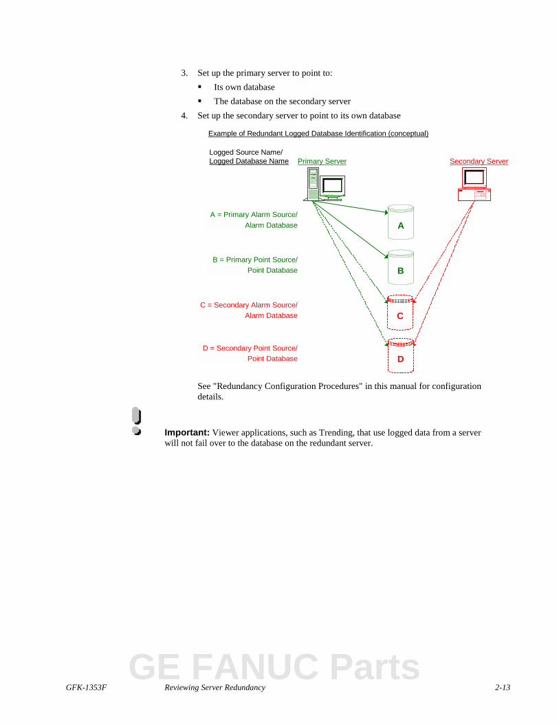
Guidelines for Redundant Logged Database IdentificationWhen you set up your redundant logged database configuration, you have to make surethat both the primary and secondary servers know where to log their own data. You alsohave to make sure that the primary server knows where the secondary server is loggingdata, in case it needs to access the secondary logged database after a failure.
When setting up redundant logged databases:
1. Set up the same database on the primary and secondary servers so you will havetwo actual databases that, under normal operation, will be identical.
2. Give the database on each redundant server:� The same name as the database on the other server� A different name Data Source Name (DSN) from the corresponding DSN
on the other server
GFK-1353F Reviewing Server Redundancy 2-13
3. Set up the primary server to point to:� Its own database� The database on the secondary server
4. Set up the secondary server to point to its own database
Primary Server Secondary Server
Example of Redundant Logged Database Identification (conceptual)
Logged Source Name/Logged Database Name
D = Secondary Point Source/Point Database
C = Secondary Alarm Source/Alarm Database
A = Primary Alarm Source/Alarm Database
B = Primary Point Source/Point Database
A
B
C
D
See "Redundancy Configuration Procedures" in this manual for configurationdetails.
Important: Viewer applications, such as Trending, that use logged data from a serverwill not fail over to the database on the redundant server.
GE FANUC Parts
2-14 CIMPLICITY HMI Server Redundancy Operation Manual–July 2001 GFK-1353F
Defining Alarm Management Behavior in Server RedundancyThe Alarm Manager on the primary server receives its updates fromCIMPLICITY services on both the primary and secondary servers.CIMPLICITY applications that generate alarms (Point Management, EventManager8 etc.) will not generate alarms when the corresponding application isrunning on the primary server.
Exceptions to this rule are:
� Device communications alarms.� Process down alarms.� Node lost alarms.
Defining User Registration in Server RedundancyA runtime database for users is maintained by User Registration on the primaryserver. This information is passed to User Registration on the secondary server.
Defining CimView Behavior in Server RedundancyCimView applications running on the primary server or viewers receive point updatesfrom the primary point manager. CimView applications running on secondary serverreceives updates from the point manager running on the secondary server. All setpointsare routed to the primary point manager. When the primary server is lost, CimViewapplications on viewers automatically begin receiving updates from the secondary pointmanager.
Important: Trend Controls on CimView screens that use logged data will not fail overto the database on the redundant server.
Defining Failover Period in a ServerCIMPLICITY Interprocess Communications has a built-in probing mechanism,independent of TCP/IP’s network probing mechanism. This was introduced so that youcan configure a smaller failover period than the TCP/IP default timeout period of 2 hours.This expedites detection of a failed node for Server Redundancy. The default time out is15 seconds.
8 From a Basic Script running in the Event Manager there is a way to force an alarm to be generated when executed
on the Slave Computer. Consult the documentation for AlarmGenerate in the Basic Control Engine LanguageReference Manual.
GFK-1353F Reviewing Server Redundancy 2-15
Manual Redundancy OverviewAlthough automatic server redundancy is an essential feature of CIMPLICITY HMI, itrequires total failure of the primary server for the secondary server to take over. There arespecific failures when you need the secondary server to take over a function or the entireproject, even when the primary server has not failed. Therefore server redundancyprovides an application interface to allow you to trigger a failover when a specific criteriais reached.
There may be a failure involving the primary server with the:
� Software, when for some reason, the:� Data collection stops� Project goes down, even though the server continues to function
� Device communication, when the:� Device connection to Point Management (PTM) is severed� All devices, Alarm Manger (AM), User Registration (UR) and Point
Management (PTM) applications lose contact with the processes
Functions to Address Specific FailuresCIMPLICITY HMI offers four functions to address these issues. They are:
For software failure:
1. Point management transfer, including data collection2. Entire project fail over
For device failure:
1. Point management transfer2. Entire project fail over
The functions reside in the Redundancy.dll and can be called by any programminglanguage, like the Basic Control Engine, that is capable of calling a DLL entry point.
The functions are:COR_BOOLEAN failover_project(COR_STATUS *retstat)
Causes the local project to shutdown.COR_BOOLEAN failover_data_collection(COR_STATUS *retstat)
Causes the current slave computer to become the current master computer.COR_BOOLEAN redundant_is_redundant()
Tells if this is a redundant project.int redundant_local_index()
Returns the index of the global point element that has the status of the local device.
Returns If on the0 Primary1 Secondary.
GE FANUC Parts

2-16 CIMPLICITY HMI Server Redundancy Operation Manual–July 2001 GFK-1353F
int redundant_remote_index()
Returns the index of the global point element that has the status of the remote device
Returns If on the0 Primary1 Secondary.
You, the system manager, will configure a specific global point and provide the logic todetermine when a changeover will occur. Basically the logic can be whatever you want,as long as it is running as part of the project.
Note: Aids that are in your CIMPLICITY HMI directory, if you installed the serverredundancy option include:
� Mon_failure.c, a sample program to review as a working example. It is locatedat:…\CIMPLICITY\Hmi\api\redundant_api\mon_failure.c
� Redundancy.h, a “C” header file that contains the prototypes for the function. Itis located at:…\CIMPLICITY\Hmi\include\inc_path\redundancy.h
Tools for Device FailureThe devcom toolkit provides the current status of a device connection to PointManagement (PTM). Whenever the status of the connection changes the devcom willsend a message to Point Management.
Point Management will set a global point based on the status of the device connection.
If there is a failure in the:
Devcom All the devices for the devcom are marked unavailableRemote PTM All of the remote devices are marked unavailableLocal PTM The application fails over to the remote PTM
The remote PTM marks the local devices as unavailable
A global BOOLEAN array point of two (2) elements indicates the status of the deviceconnection.
The value of: Indicates that the devcom:1 Is communicating with the device0 Is not communicating with the device

GFK-1353F Reviewing Server Redundancy 2-17
Adhering to Point Requirements for Manual Server RedundancyThe point you create to determine when either data collection or the entire project shouldbe transferred to the secondary server is very specific. It must meet four conditions. Itmust:
1. Have the same name as the name of the device.2. Be a Boolean point.3. Have two (2) elements (for example, the status of the device on the primary
server and the status of the device on the secondary server).4. Be a global point.
Transferring Point Management Manually (Including DataCollection)
In a normal state the primary server carries out several processes that can be classified aspoint management.
Point management includes:
� Data collection� Virtual point processing� Sending information to CimView screens
If the primary server stops collecting data from one device, but is still running andcommunicating with the secondary computer, there is no automatic fail over.
Under these circumstances or for whatever reasons you specify, you can manuallytransfer point management from the primary to the secondary server.
After the transfer the:
� Primary server maintains control of processes such as:Software� Database logging� Alarm viewer� Base control engine
Devcom
� Alarm Manager (AM)� User Registration (UR)� Point Management (PTM)
� Secondary server takes over point management
To manually transfer point management from the primary to secondaryserver:
1. Create a specific Boolean point with the same name as the device beingmonitored.
2. Call this function:failover_data_collection()
3. Specify what actions should occur if the point changes from 1 to 0 through aBasic script.
GE FANUC Parts
2-18 CIMPLICITY HMI Server Redundancy Operation Manual–July 2001 GFK-1353F
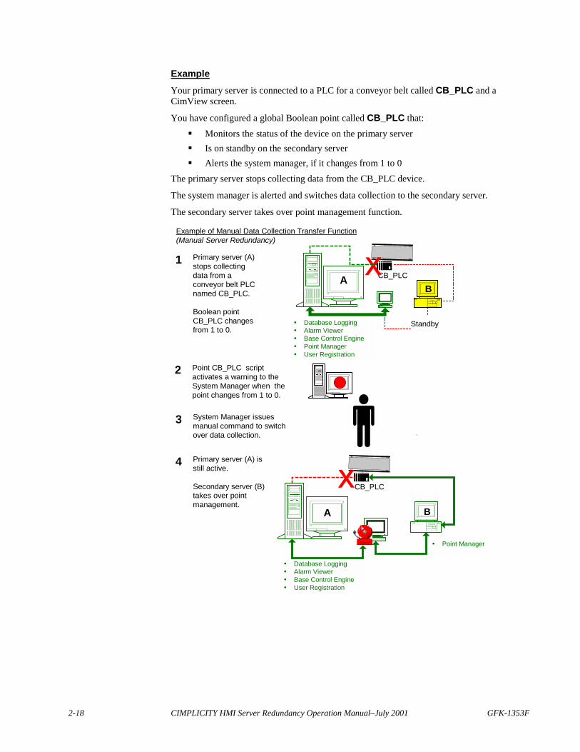
ExampleYour primary server is connected to a PLC for a conveyor belt called CB_PLC and aCimView screen.
You have configured a global Boolean point called CB_PLC that:
� Monitors the status of the device on the primary server� Is on standby on the secondary server� Alerts the system manager, if it changes from 1 to 0
The primary server stops collecting data from the CB_PLC device.
The system manager is alerted and switches data collection to the secondary server.
The secondary server takes over point management function.
3
2
1 Primary server (A)stops collectingdata from aconveyor belt PLCnamed CB_PLC.
Boolean pointCB_PLC changesfrom 1 to 0.
System Manager issuesmanual command to switchover data collection.
4
CB_PLC
Standby
Primary server (A) isstill active.
Secondary server (B)takes over pointmanagement.
A
Example of Manual Data Collection Transfer Function(Manual Server Redundancy)
CB_PLC
A
� Database Logging� Alarm Viewer� Base Control Engine� Point Manager� User Registration
� Database Logging� Alarm Viewer� Base Control Engine� User Registration
� Point Manager
B
Point CB_PLC scriptactivates a warning to theSystem Manager when thepoint changes from 1 to 0.
B

GFK-1353F Reviewing Server Redundancy 2-19
Forcing Manual Project TransferIn a normal state the primary server is the active server.
The active server controls all the processes in the project.
If the primary server loses contact with one device, but is still running andcommunicating with the secondary server, there is no automatic fail over.
Under these circumstances or, for whatever reasons you specify, you can manually forcea fail over from the primary to the secondary server.
To manually force a project transfer:1. Create a specific Boolean point with the same name as the device being
monitored.2. Call the function:
failover_project ()
3. Specify what actions should occur if the point changes from 1 to 0 through aBasic script.
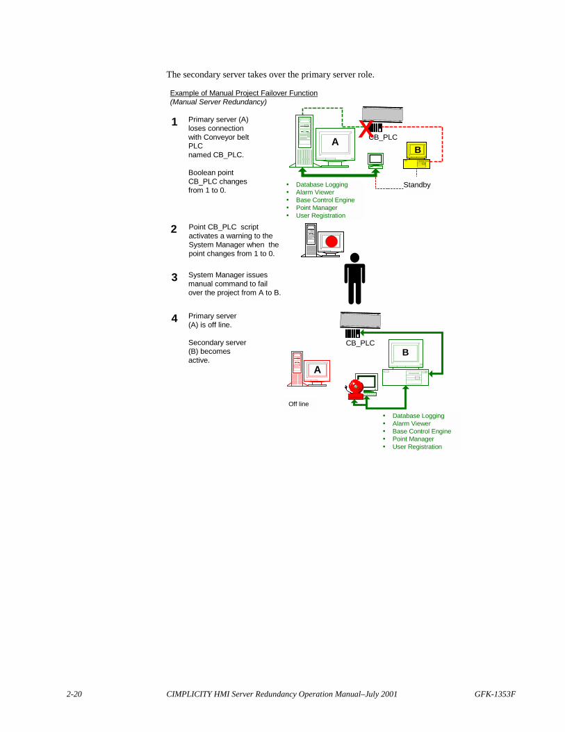
ExampleYour primary server is connected to a PLC for a conveyor belt called CB_PLC and aCimView screen.
You have configured a global Boolean point called CB_PLC that:
� Monitors the status of the device on the primary server� Is on standby on the secondary server� Alerts the system manager, if it changes from 1 to 0
The primary server loses connection with the CB_PLC device.
The system manager is alerted and fails over the entire project from the primary to thesecondary server.
GE FANUC Parts
2-20 CIMPLICITY HMI Server Redundancy Operation Manual–July 2001 GFK-1353F
The secondary server takes over the primary server role.
3
Point CB_PLC scriptactivates a warning to theSystem Manager when thepoint changes from 1 to 0.
2
1 Primary server (A)loses connectionwith Conveyor beltPLCnamed CB_PLC.
Boolean pointCB_PLC changesfrom 1 to 0.
System Manager issuesmanual command to failover the project from A to B.
4
CB_PLC
Standby
Primary server(A) is off line.
Secondary server(B) becomesactive.
A
Example of Manual Project Failover Function(Manual Server Redundancy)
CB_PLC
A
� Database Logging� Alarm Viewer� Base Control Engine� Point Manager� User Registration
B
B
� Database Logging� Alarm Viewer� Base Control Engine� Point Manager� User Registration
Off line
GFK-1353F 3-1
Configuring Server Redundancy
About Redundancy Configuration ProceduresThis chapter documents the configuration procedures needed to support ServerRedundancy for CIMPLICITY HMI for Windows NT.
Before you begin configuration, make sure that the same version of CIMPLICITYsoftware is installed and licensed on both servers of each redundant pair as described inthe CIMPLICITY Base System User Manual (GFK-1180). In addition, you must install allrequired application options, protocols and databases software on both computers.
Review:
� Base System configuration.� Database logging configuration.
Base System ConfigurationConfigure the base system in the following order. :
Configure:
1. A project.2. A network and verify configuration.3. Device communications.
Important: You need to install the redundancy option on all Viewers.
Note: Global points are obsolete in CIMPLICITY 5.0. Instead use the points that arecreated in the redundancy object. See the "Using the Redundancy Object" chapter in thismanual for details.
GE FANUC Parts
3-2 CIMPLICITY HMI Server Redundancy Operation Manual–July 2001 GFK-1353F
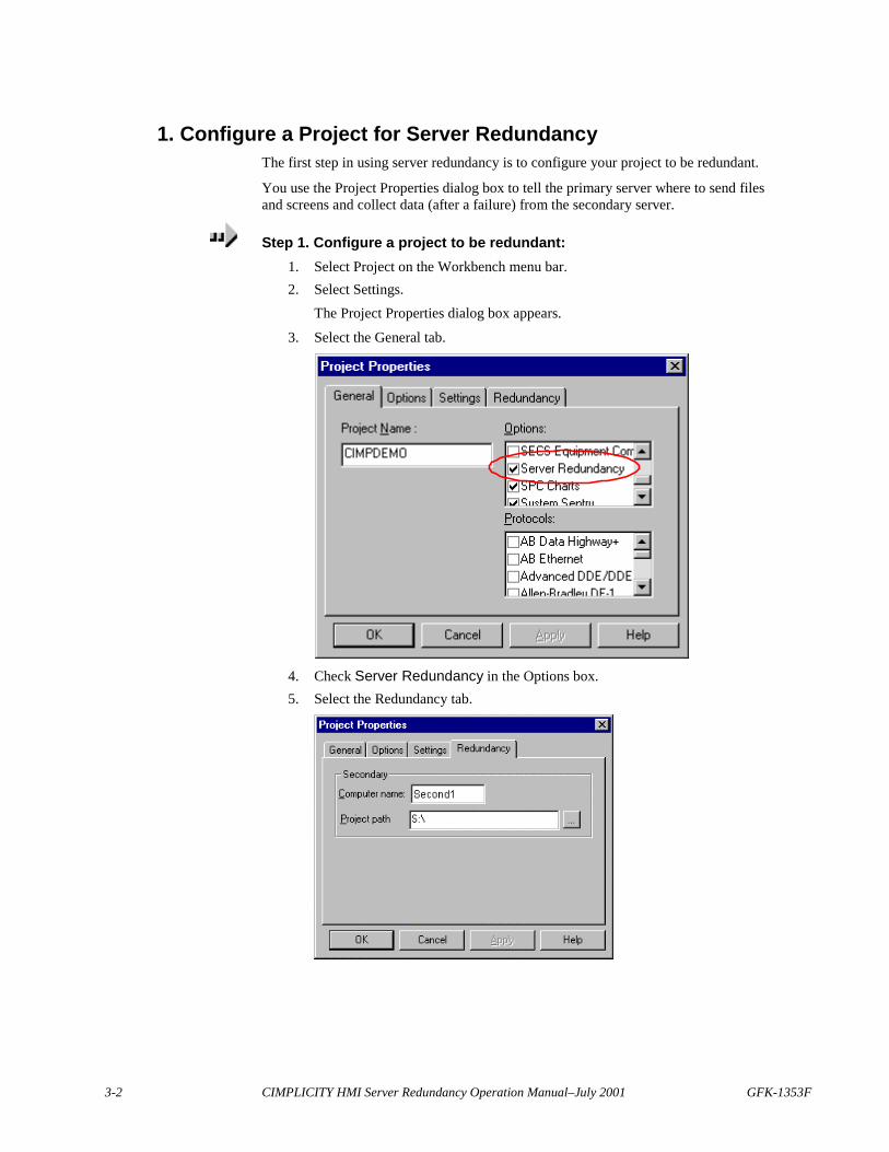
1. Configure a Project for Server RedundancyThe first step in using server redundancy is to configure your project to be redundant.
You use the Project Properties dialog box to tell the primary server where to send filesand screens and collect data (after a failure) from the secondary server.
Step 1. Configure a project to be redundant:1. Select Project on the Workbench menu bar.2. Select Settings.
The Project Properties dialog box appears.
3. Select the General tab.
4. Check Server Redundancy in the Options box.5. Select the Redundancy tab.
GFK-1353F Configuring Server Redundancy 3-3
6. Enter the following information in the Redundancy tab:Computer name Enter the name of the secondary Server.Project path Enter the directory on the secondary Server
where the CIMPLICITY project will be stored.
The drive must be a mapped drive on the primaryserver.
UNC filenames are not supported.
Configuration files and screens are copied from the primary server to the Projectpath whenever a Configuration Update is performed.
Important: Make sure you configure the logging setup on both the primary andsecondary server through the Database Logger in the CIMPLICITY HMI Workbench. See"Managing Database Logging" in the CIMPLICITY HMI Base System User's Manual.
2. Configure Networks for Server RedundancyThe second step when configuring a base system for server redundancy is to configureand verify the network.
Configuration includes host names.
Important: SR requires that all computers (primary, secondary and viewer) must havetheir names and IP addresses configured and these names must match the actual computernames. You may configure the host names in DNS, WINS or in the local host file oneach computer, depending on the networking resources available at your site. SR will notfunction correctly if this information is not configured. If you do not understand networkconfiguration you should obtain the services of someone that does.
Once the configuration is complete, the following tests should be run.
1. From the primary computer ping primary, secondary and all viewers by nameand by address.
2. From the secondary computer ping primary, secondary and all viewers by nameand by address.
3. From each viewer, ping primary and secondary by name and address.4. Verify computer names of each computer match.
Note: Keep alives are automatically configured on a:� Server when redundancy is installed and� Viewer when Viewer redundancy is installed.
The following example demonstrates how to ping by name, by address and determine thecomputer name.
GE FANUC Parts

3-4 CIMPLICITY HMI Server Redundancy Operation Manual–July 2001 GFK-1353F
C:\WINNT\system32>ping albsagp2
Pinging albsagp2 [3.26.4.215] with 32 bytes of data:
Reply from 3.26.4.215: bytes=32 time<10ms TTL=128
Reply from 3.26.4.215: bytes=32 time<10ms TTL=128
Reply from 3.26.4.215: bytes=32 time<10ms TTL=128
C:\WINNT\system32>ping -a 3.26.4.215
Pinging ALBSAGP2 [3.26.4.215] with 32 bytes of data:
Reply from 3.26.4.215: bytes=32 time<10ms TTL=128
Reply from 3.26.4.215: bytes=32 time<10ms TTL=128
Reply from 3.26.4.215: bytes=32 time<10ms TTL=128
C:\WINNT\system32>set computername
COMPUTERNAME=ALBSAGP2
C:\WINNT\system32>
To verify names using the above example as a reference.To Verify Names Referencing the Above ExamplePing by Name ping albsagp2 first translates albsagp2 to an IP
Address and then verifies communication to thecomputer.
albsagp2 has an IP address of 3.26.4.215.
The time required to Ping must be less than 10ms betweenprimary and secondary and less than 30ms betweenviewers.
This step verifies that the network software can convert ahostname to an IP Address.
Ping by Address Type ping –a 3.26.4.215.The output of ping albsagp2 provides the IP Address.
This step verifies that the network software can convertthe IP Address back to the same node name as entered inthe first step. If you obtain a different IP Address backthis may indicate that you have duplicate entries for the IPAddress in you network lookup tables. This must becorrected before continuing.
Continue Pinging In this example we just ping one computer.
You would continue to ping the other computers(secondary, viewers, etc)
Check Computer Names Type set computername to return the current setting.
This final step on each computer is determines if thesystem's computer name is the same as the computername configured in the network. This setting must matchthe name returned in the above two tests. If not this mustbe corrected by either changing your computername orchanging the network software configuration beforecontinuing.
GFK-1353F Configuring Server Redundancy 3-5
3. Configure Device Communications for Server RedundancySpecific Device Communications configuration such a driver or interface cardconfiguration will need to be configured and tested on the secondary before startingredundancy. Consult the appropriate device communications manual for additionaldetails.
Unsolicited DataThe Device Communications module receives and processes unsolicited data reportedfrom factory devices.
Unsolicited data must be directed to the to the secondary server in addition to the primaryserver, so it can be processed by the Device Communications/Point Manager on thesecondary server when the primary server fails.
4. Configure Global Points for Server RedundanciesThe next step is to configure virtual points to track redundant server status during systemoperation. The points have the following requirements:
� Naming convention is:� MASTER_PTM_RP for the primary server� SLAVE_PTM_RP for the secondary server
� Type is virtual� Class is Digital� Calculation for the point is None (default).
A point will take on a value of:
� 1 if the server it represents is currently operating as the primary server� 0 if the server is the secondary server
The current Primary Point Manager will only change the values. This implies that pointupdates to the global points will occur when:
� There is a redundant server failure� Redundant servers are synchronized at startup� An orderly transition from secondary to primary server occurs.
Important: If you are using point lines in Trending that automatically look for the datasource, you must configure MASTER_PTM_RP and SLAVE_PTM_RP. These are the pointsthat Trending needs to failover to the secondary server if the primary is down.
GE FANUC Parts
3-6 CIMPLICITY HMI Server Redundancy Operation Manual–July 2001 GFK-1353F
Database Logging ConfigurationWhen you set up the same database on the primary and secondary server (so you willhave two actual databases that, under normal operation, will be identical) you need toidentify them for data logging. You do this by making entries in the:
� Windows ODBC Data Source Administrator dialog box� CIMPLICITY HMI Logging Properties dialog box.
In logged database redundancy, you need to configure CIMPLICITY logging redundancyon both the primary and secondary server through Windows NTcontrol panels.
Configuring Windows ODBC Data Source Administrator
Important: Viewer applications, such as Trending, that use logged data from a primaryserver will not fail over to the database on the redundant server.
Caution: On the primary server, make sure you have specified the redundant server inthe CIMPLICITY HMI Workbench under Settings found on the Workbench menu bar.
Redundant Database Setup Using an SQL ServerFollow procedures for five basic steps to configure, in the ODBC Data SourceAdministrator, a redundant database setup using an SQL server. The steps are:
Step 1. Display the System DSN tab. See page 3-7.
Step 2. Select the driver for a new data source. See page 3-8.
Step 3. Configure the primary data source on the primary server. See page 3-8.
Step 4. Configure the secondary data source on the primary server. See page 3-12.
Step 5 Repeat Steps 1-4 on the secondary server.
When you complete this setup, go to the Logging Properties dialog box in theCIMPLICITY Workbench to identify the files you have set up. See page 3-15 for details.
GFK-1353F Configuring Server Redundancy 3-7
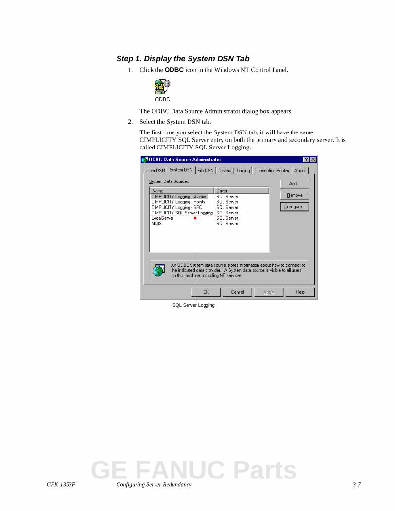
Step 1. Display the System DSN Tab1. Click the ODBC icon in the Windows NT Control Panel.
The ODBC Data Source Administrator dialog box appears.
2. Select the System DSN tab.
The first time you select the System DSN tab, it will have the sameCIMPLICITY SQL Server entry on both the primary and secondary server. It iscalled CIMPLICITY SQL Server Logging.
SQL Server Logging
GE FANUC Parts
3-8 CIMPLICITY HMI Server Redundancy Operation Manual–July 2001 GFK-1353F
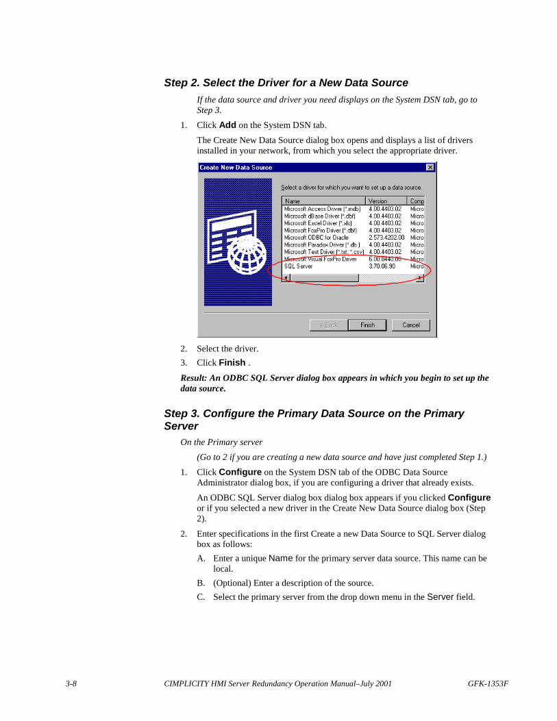
Step 2. Select the Driver for a New Data SourceIf the data source and driver you need displays on the System DSN tab, go toStep 3.
1. Click Add on the System DSN tab.
The Create New Data Source dialog box opens and displays a list of driversinstalled in your network, from which you select the appropriate driver.
2. Select the driver.3. Click Finish .Result: An ODBC SQL Server dialog box appears in which you begin to set up thedata source.
Step 3. Configure the Primary Data Source on the PrimaryServer
On the Primary server(Go to 2 if you are creating a new data source and have just completed Step 1.)
1. Click Configure on the System DSN tab of the ODBC Data SourceAdministrator dialog box, if you are configuring a driver that already exists.
An ODBC SQL Server dialog box dialog box appears if you clicked Configureor if you selected a new driver in the Create New Data Source dialog box (Step2).
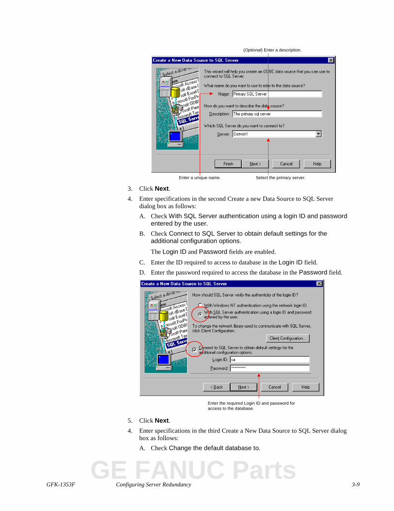
2. Enter specifications in the first Create a new Data Source to SQL Server dialogbox as follows:A. Enter a unique Name for the primary server data source. This name can be
local.B. (Optional) Enter a description of the source.C. Select the primary server from the drop down menu in the Server field.
GFK-1353F Configuring Server Redundancy 3-9
Enter a unique name.
(Optional) Enter a description.
Select the primary server.
3. Click Next.4. Enter specifications in the second Create a new Data Source to SQL Server
dialog box as follows:A. Check With SQL Server authentication using a login ID and password
entered by the user.B. Check Connect to SQL Server to obtain default settings for the
additional configuration options.
The Login ID and Password fields are enabled.C. Enter the ID required to access to database in the Login ID field.D. Enter the password required to access the database in the Password field.
Enter the required Login ID and password foraccess to the database.
5. Click Next.4. Enter specifications in the third Create a New Data Source to SQL Server dialog
box as follows:A. Check Change the default database to.
GE FANUC Parts
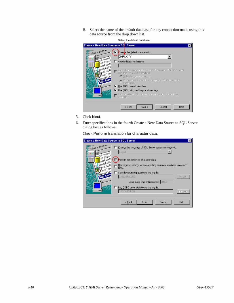
3-10 CIMPLICITY HMI Server Redundancy Operation Manual–July 2001 GFK-1353F
B. Select the name of the default database for any connection made using thisdata source from the drop down list.
Select the default database.
5. Click Next.6. Enter specifications in the fourth Create a New Data Source to SQL Server
dialog box as follows:
Check Perform translation for character data.
GFK-1353F Configuring Server Redundancy 3-11
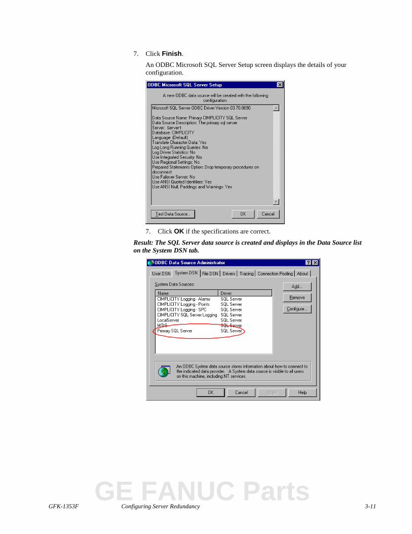
7. Click Finish.
An ODBC Microsoft SQL Server Setup screen displays the details of yourconfiguration.
7. Click OK if the specifications are correct.
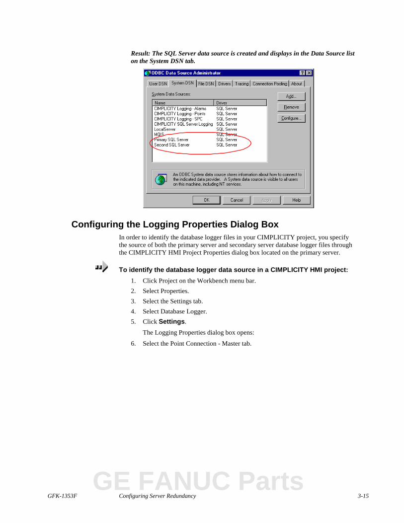
Result: The SQL Server data source is created and displays in the Data Source liston the System DSN tab.
GE FANUC Parts
3-12 CIMPLICITY HMI Server Redundancy Operation Manual–July 2001 GFK-1353F
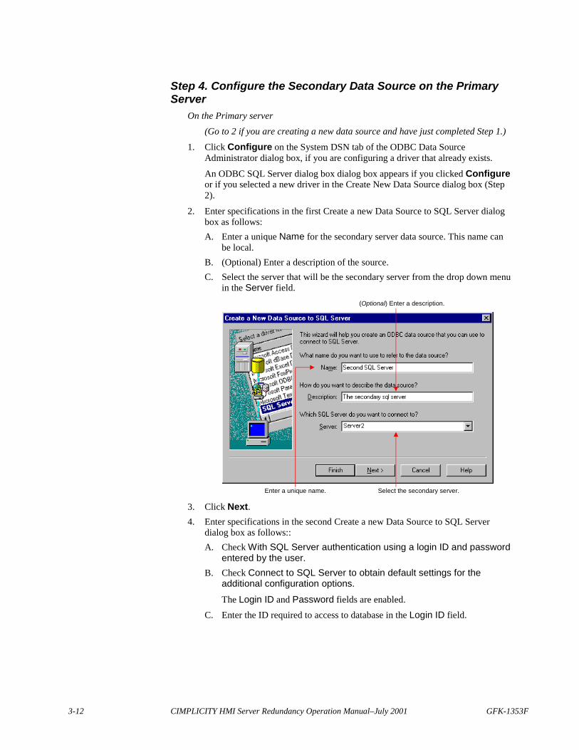
Step 4. Configure the Secondary Data Source on the PrimaryServer
On the Primary server(Go to 2 if you are creating a new data source and have just completed Step 1.)
1. Click Configure on the System DSN tab of the ODBC Data SourceAdministrator dialog box, if you are configuring a driver that already exists.
An ODBC SQL Server dialog box dialog box appears if you clicked Configureor if you selected a new driver in the Create New Data Source dialog box (Step2).
2. Enter specifications in the first Create a new Data Source to SQL Server dialogbox as follows:A. Enter a unique Name for the secondary server data source. This name can
be local.B. (Optional) Enter a description of the source.C. Select the server that will be the secondary server from the drop down menu
in the Server field.
Enter a unique name.
(Optional) Enter a description.
Select the secondary server.
3. Click Next.4. Enter specifications in the second Create a new Data Source to SQL Server
dialog box as follows::A. Check With SQL Server authentication using a login ID and password
entered by the user.B. Check Connect to SQL Server to obtain default settings for the
additional configuration options.
The Login ID and Password fields are enabled.C. Enter the ID required to access to database in the Login ID field.
GFK-1353F Configuring Server Redundancy 3-13
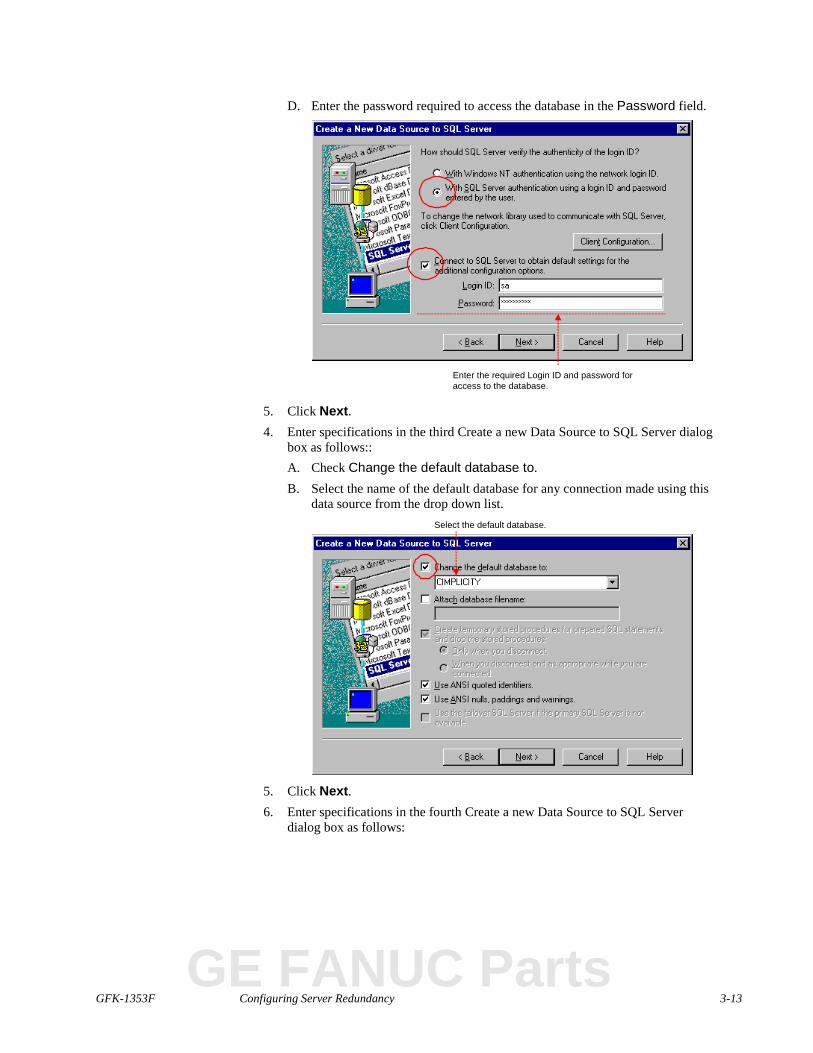
D. Enter the password required to access the database in the Password field.
Enter the required Login ID and password foraccess to the database.
5. Click Next.4. Enter specifications in the third Create a new Data Source to SQL Server dialog
box as follows::A. Check Change the default database to.B. Select the name of the default database for any connection made using this
data source from the drop down list.Select the default database.
5. Click Next.6. Enter specifications in the fourth Create a new Data Source to SQL Server
dialog box as follows:
GE FANUC Parts
3-14 CIMPLICITY HMI Server Redundancy Operation Manual–July 2001 GFK-1353F
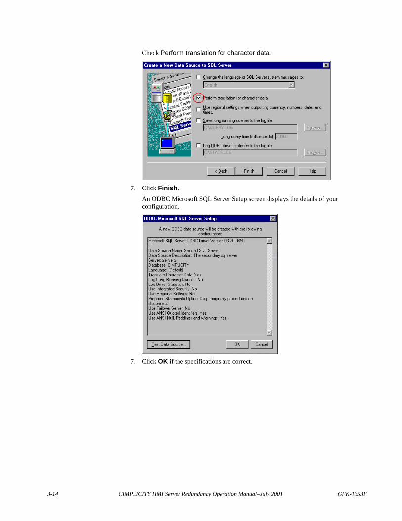
Check Perform translation for character data.
7. Click Finish.
An ODBC Microsoft SQL Server Setup screen displays the details of yourconfiguration.
7. Click OK if the specifications are correct.
GFK-1353F Configuring Server Redundancy 3-15
Result: The SQL Server data source is created and displays in the Data Source liston the System DSN tab.
Configuring the Logging Properties Dialog BoxIn order to identify the database logger files in your CIMPLICITY project, you specifythe source of both the primary server and secondary server database logger files throughthe CIMPLICITY HMI Project Properties dialog box located on the primary server.
To identify the database logger data source in a CIMPLICITY HMI project:1. Click Project on the Workbench menu bar.2. Select Properties.3. Select the Settings tab.4. Select Database Logger.5. Click Settings.
The Logging Properties dialog box opens:
6. Select the Point Connection - Master tab.
GE FANUC Parts
3-16 CIMPLICITY HMI Server Redundancy Operation Manual–July 2001 GFK-1353F
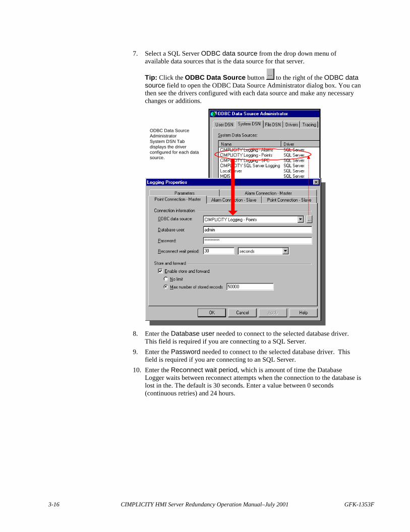
7. Select a SQL Server ODBC data source from the drop down menu ofavailable data sources that is the data source for that server.
Tip: Click the ODBC Data Source button to the right of the ODBC datasource field to open the ODBC Data Source Administrator dialog box. You canthen see the drivers configured with each data source and make any necessarychanges or additions.
ODBC Data SourceAdministratorSystem DSN Tabdisplays the driverconfigured for each datasource.
8. Enter the Database user needed to connect to the selected database driver.This field is required if you are connecting to a SQL Server.
9. Enter the Password needed to connect to the selected database driver. Thisfield is required if you are connecting to an SQL Server.
10. Enter the Reconnect wait period, which is amount of time the DatabaseLogger waits between reconnect attempts when the connection to the database islost in the. The default is 30 seconds. Enter a value between 0 seconds(continuous retries) and 24 hours.

GFK-1353F Configuring Server Redundancy 3-17
11. Check the Enable Store and Forward check box to enable Store and Forward.After you enable the feature, use the radio buttons to select between unlimited orlimited storage of database records.Unlimited Database Logger stores an unlimited number
of records while its connection to thedatabase is down. The number of recordsactually stored is determined by the amountof time the connection is lost and by theamount of free disk space you have.
Max number of stored records Database Logger stores a specified numberof records when its connection to thedatabase is down. Enter a number between 1and 4,294,967,295.
12. Repeat these steps for the other three tabs so you will have configured all fourtabs:Point Connection - Master Primary (master)Point Connection - Slave Second (slave)Alarm Connection - Master PrimaryAlarm Connection - Slave Second
13. Click OK or select the Parameters tab.
Result: CIMPLICITY validates your entries. If the Data Logger is unable toconnect to the selected database, validation fails.
Important: On each tab, make sure that you select the correct data source for thecomputer (master / slave) that the tab represents.
Guidelines and notes about specific data sources:1. CIMPLICITY SQL Server Logging
A Microsoft SQL Server data source that logs data to an on-node SQL Serverdatabase. You must install SQL Server (sold separately) to use this data source.
If you are connecting to a SQL Server, you may be prompted for a databasename during validation.
2. Oracle DatabaseYou may see the ODBC data source that you created for Oracle.
You may be prompted for a Server ID during validation. Enter the Alias Namefor the Oracle database in this field.
GE FANUC Parts


GFK-1353F 4-1
Using the Redundancy Object
About the Redundancy ObjectWhen you activate the server redundancy option in the Workbench, CIMPLICITYautomatically installs a Redundancy object, which is an object of the redundancy class.
The Redundancy object enables you to easily:
� View whether or not the primary and/or secondary server is running,� Switch the master role from one server to the other when you need to take the
current master offline,� Switch the master back when the original master is brought back on line and� Configures a set of point to use in your application.
This capability enables you to efficiently switch control back and forth while ensuringthat data is not lost.
CIMPLICITY Redundancy object
� Displays whichserver is thecurrent master.
� Enables you toswitch themaster rolefrom one serverto the other
GE FANUC Parts
4-2 CIMPLICITY HMI Server Redundancy Operation Manual–July 2001 GFK-1353F
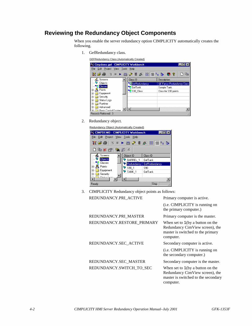
Reviewing the Redundancy Object ComponentsWhen you enable the server redundancy option CIMPLICITY automatically creates thefollowing.
1. GefRedundancy class.GEFRedundancy Class (Automatically Created)
2. Redundancy object.Redundancy Object (Automatically Created)
3. CIMPLICITY Redundancy object points as follows:REDUNDANCY.PRI_ACTIVE Primary computer is active.
(i.e. CIMPLICITY is running onthe primary computer.)
REDUNDANCY.PRI_MASTER Primary computer is the master.REDUNDANCY.RESTORE_PRIMARY When set to 1(by a button on the
Redundancy CimView screen), themaster is switched to the primarycomputer.
REDUNDANCY.SEC_ACTIVE Secondary computer is active.
(i.e. CIMPLICITY is running onthe secondary computer.)
REDUNDANCY.SEC_MASTER Secondary computer is the master.REDUNDANCY.SWITCH_TO_SEC When set to 1(by a button on the
Redundancy CimView screen), themaster is switched to the secondarycomputer.
GFK-1353F Using the Redundancy Object 4-3
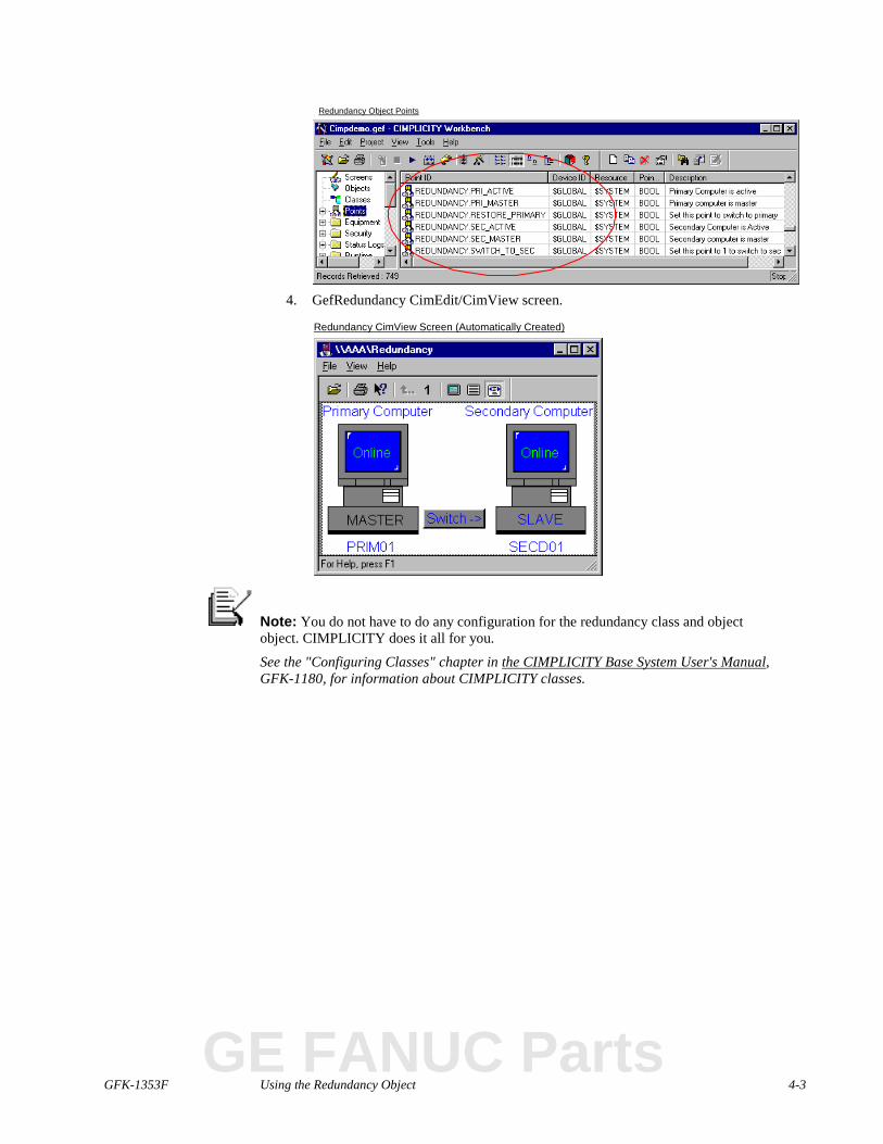
Redundancy Object Points
4. GefRedundancy CimEdit/CimView screen.
Redundancy CimView Screen (Automatically Created)
Note: You do not have to do any configuration for the redundancy class and objectobject. CIMPLICITY does it all for you.
See the "Configuring Classes" chapter in the CIMPLICITY Base System User's Manual,GFK-1180, for information about CIMPLICITY classes.
GE FANUC Parts
4-4 CIMPLICITY HMI Server Redundancy Operation Manual–July 2001 GFK-1353F
Redundancy Object UseThe Redundancy object is straightforward to use.
Steps to use the Redundancy object are:
Step 1. Display the Redundancy CimView screen.
Step 2. Monitor the servers through the Redundancy screen.
Step 3. Switch the master role between redundant computers.
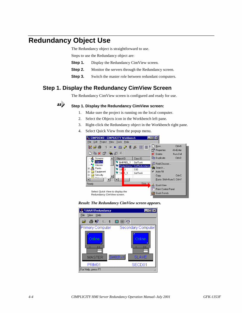
Step 1. Display the Redundancy CimView ScreenThe Redundancy CimView screen is configured and ready for use.
Step 1. Display the Redundancy CimView screen:1. Make sure the project is running on the local computer.2. Select the Objects icon in the Workbench left pane.3. Right-click the Redundancy object in the Workbench right pane.4. Select Quick View from the popup menu.
Select Quick View to display theRedundancy CimView screen.
Result: The Redundancy CimView screen appears.
GFK-1353F Using the Redundancy Object 4-5
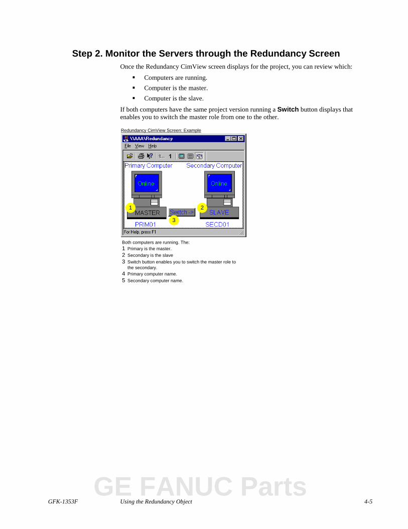
Step 2. Monitor the Servers through the Redundancy ScreenOnce the Redundancy CimView screen displays for the project, you can review which:
� Computers are running.� Computer is the master.� Computer is the slave.
If both computers have the same project version running a Switch button displays thatenables you to switch the master role from one to the other.
Redundancy CimView Screen: Example
Both computers are running. The:1 Primary is the master.2 Secondary is the slave3 Switch button enables you to switch the master role to
the secondary.4 Primary computer name.5 Secondary computer name.
1 2
3
GE FANUC Parts
4-6 CIMPLICITY HMI Server Redundancy Operation Manual–July 2001 GFK-1353F
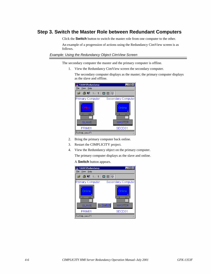
Step 3. Switch the Master Role between Redundant ComputersClick the Switch button to switch the master role from one computer to the other.
An example of a progression of actions using the Redundancy CimView screen is asfollows.
Example: Using the Redundancy Object CimView Screen
The secondary computer the master and the primary computer is offline.
1. View the Redundancy CimView screen the secondary computer.
The secondary computer displays as the master; the primary computer displaysas the slave and offline.
2. Bring the primary computer back online.3. Restart the CIMPLICITY project.4. View the Redundancy object on the primary computer.
The primary computer displays as the slave and online.
A Switch button appears.
GFK-1353F Using the Redundancy Object 4-7
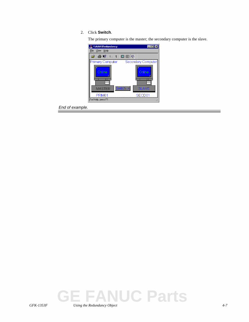
2. Click Switch.
The primary computer is the master; the secondary computer is the slave.
End of example.
GE FANUC Parts

GFK-1353F 5-1
Recovery Procedures
Normal Operating ProceduresNormal operating procedures in server redundancy involve:
� Run and stop redundant CIMPLICITY projects.� Starting a project from the secondary server.� Configuring the project to start on both the primary and secondary servers when
they power up.
This section describes how to insure that the operating procedures performsmoothly.
Starting and Stopping Redundant CIMPLICITY ProjectsWhen all hardware is working correctly, CIMPLICITY software can be started and shutdown using the Run and Stop tools in the CIMPLICITY Workbench on the primaryserver.
Important: Under most circumstances you should use the Workbench to start redundantprojects. This is because the Workbench:
1. Allows you to start up both systems in one coordinated action. (If you useCIMPLICITY Options to startup on the primary, you need to wait for theprimary to finish its startup and then start the secondary.)
2. Will update the slave node configuration as required before starting the project,making sure that the master and slave nodes are synchronized.
A rare exception to normal startup occurs if, there is a catastrophic event that forces bothcomputers to shut down, e.g. the power failed. In this situation, the last active master mustbe the first restarted to ensure data integrity in the following areas:
� Manual mode data and values.� Saved point values.
If, the secondary server was the only computer running before shutting down, it shouldstart first, as the master. Data that was collected before the shutdown can then be failedover to the primary server before it is reinstated as the master.
GE FANUC Parts
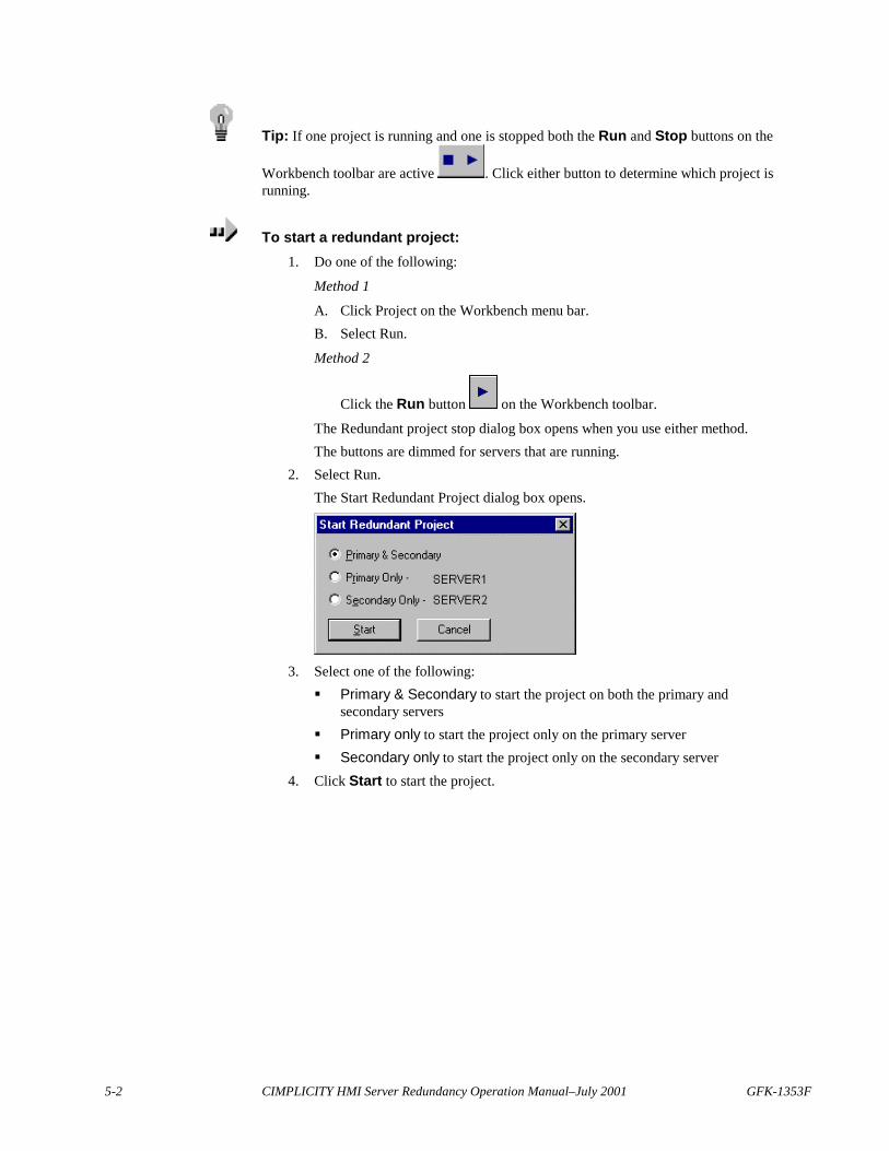
5-2 CIMPLICITY HMI Server Redundancy Operation Manual–July 2001 GFK-1353F
Tip: If one project is running and one is stopped both the Run and Stop buttons on the
Workbench toolbar are active . Click either button to determine which project isrunning.
To start a redundant project:1. Do one of the following:
Method 1
A. Click Project on the Workbench menu bar.B. Select Run.
Method 2
Click the Run button on the Workbench toolbar.
The Redundant project stop dialog box opens when you use either method.The buttons are dimmed for servers that are running.
2. Select Run.The Start Redundant Project dialog box opens.
3. Select one of the following:� Primary & Secondary to start the project on both the primary and
secondary servers� Primary only to start the project only on the primary server� Secondary only to start the project only on the secondary server
4. Click Start to start the project.
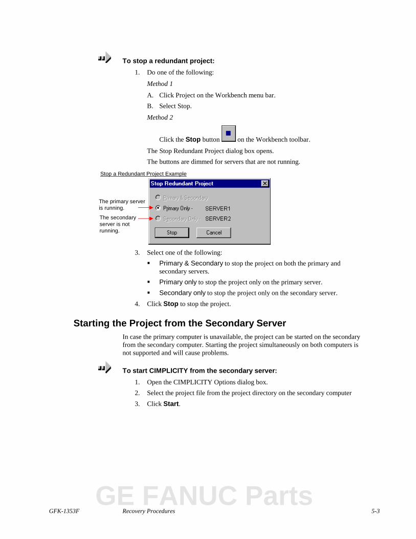
GFK-1353F Recovery Procedures 5-3
To stop a redundant project:1. Do one of the following:
Method 1
A. Click Project on the Workbench menu bar.B. Select Stop.
Method 2
Click the Stop button on the Workbench toolbar.
The Stop Redundant Project dialog box opens.The buttons are dimmed for servers that are not running.
Stop a Redundant Project Example
The primary serveris running.
The secondaryserver is notrunning.
3. Select one of the following:� Primary & Secondary to stop the project on both the primary and
secondary servers.� Primary only to stop the project only on the primary server.� Secondary only to stop the project only on the secondary server.
4. Click Stop to stop the project.
Starting the Project from the Secondary ServerIn case the primary computer is unavailable, the project can be started on the secondaryfrom the secondary computer. Starting the project simultaneously on both computers isnot supported and will cause problems.
To start CIMPLICITY from the secondary server:1. Open the CIMPLICITY Options dialog box.2. Select the project file from the project directory on the secondary computer3. Click Start.
GE FANUC Parts

5-4 CIMPLICITY HMI Server Redundancy Operation Manual–July 2001 GFK-1353F
Configuring the Project to Start at BootThe project can be configured to start on both the primary and secondary computers whenthey power up.
Important: Make sure that the projects do not start at the same time if they areconfigured to start on both the primary and secondary computers when they power up.Failure to ensure this can result in both computers considering themselves the master.
To provide a mechanism for dealing with a Power On situation where both computersboot at the same time you can configure a parameter to delay the secondary computer'sstartup until the primary is complete.
To delay the secondary computer's startup until the primary is running:Configure the following global parameter in the project.
SLAVE_STARTUP_TIMOUT|1|<TIME-MINUTES>
Where
Time-minutes Is the amount of time it takes for the project to start on the primarycomputer plus an additional minute.
This value you empirically determine by measuring the startup time onthe master.
See the appendix "Configuration Parameters" in this manual for more details aboutserver redundancy configuration parameters.
Note: It is recommended that you use the Workbench to start redundant projects.
GFK-1353F Recovery Procedures 5-5
Primary Server FailureWhen the server fails in automatic server redundancy, the secondary server automaticallytakes control. Then, you, the system manager, have to:
� Find the cause of the problem.� Reset the primary server after recovery.� Synchronize database logging files.
When you have finished, redundancy will return to normal.
Understanding System Operation during FailoverWhen the primary server of a redundant pair fails, the secondary server goes from standbyto active mode to insure that all essential areas in the project continue to operate.
Areas include:
� Device communications and point management.� Alarm management.� User logons.� Runtime interfaces.
Device Communications and Point ManagementDevice Communications on the secondary server begins actively polling for data andpasses point data to the Point Manager on the secondary server, which now becomes theprimary Point Manager. Any viewer process that was connected to the original primaryPoint Manager will automatically switch over to the new primary Point Manager, whichwill now assume all supervisory and control functions.
Note: Between the time that the primary server is lost and before the secondary servertakes over, users may notice an interruption in system performance. During this time,point values will not be updated, setpoints and alarm acknowledgments will not complete,and users will not be able to log on or off.
Alarm ManagementThe Alarm Manager on the secondary server becomes the primary Alarm Manager. Noalarm data is lost because the Alarm Manager on the primary server continually updatedthe alarm list for the Alarm Manager on the secondary server. The new primary AlarmManager will now process all alarm updates and provide alarm information to allinterested processes.
User LogonsThe User Registration process on the secondary server becomes the primary UserRegistration process. No user registration data is lost because User Registration on theprimary server continually updated the user list for User Registration on the secondaryserver. The new primary User Registration will now process all user logins and logoutsand provide information on user views.
GE FANUC Parts
5-6 CIMPLICITY HMI Server Redundancy Operation Manual–July 2001 GFK-1353F
Runtime InterfacesWhen the primary server fails, all CimView, Alarm Viewer and Point Control Panelsessions running on that server are lost.
� CIMPLICITY user interface accessed from console on the primary server.
When the primary server fails, this console is no longer usable. The user willhave to move to the console on the secondary server, log in, and access theCIMPLICITY user interface from there.
� CIMPLICITY user interface accessed from a Viewer.
The user interfaces will fail over to the new master.
Detecting the Cause of Primary Server FailureServer failure may be due to:
� CIMPLICITY software shutdown on either server� Network failure between the primary and secondary servers� Loss of server due to loss of power or equipment failure
Server failure is detected by the IPC Router, which is the communications process thatruns on each server.
1. The Router sets up links to each server in the system and sends messages to eachnode at a set interval.
The probe interval is defined in REDUND_PROBE_DELAY which is set to1000 milliseconds by default.
2. If no reply is received from the server for a set number of tries (defined inREDUND_PROBE_COUNT) the server is then declared to have failed.
3. The Router sends a "Partner Dead" message to any processes that haveoutstanding messages to processes on that server.
Server failure may be detected on a primary server, secondary server or Viewer.
� When a secondary server fails, functionality is not lost, because all functions arealso running on the primary server.
� When a primary server fails, the secondary server initiates procedures to takeover redundant CIMPLICITY functions.

GFK-1353F Recovery Procedures 5-7
Resetting the Primary Server after RecoveryAfter a primary server has failed and recovered, processes on the secondary server needto be told that the primary sever is now available. The Redundancy object provides astraightforward way to reset the primary server. CIMPLICITY automatically displays thisobject when the redundancy feature is activated.
To reset the primary server on CIMPLICITY:1. Make sure that CIMPLICITY software is running on the primary and secondary
servers.2. Start a project's Workbench on the primary server.3. Select the Objects icon in the Workbench left pane.4. Right-click the Redundancy object.5. Select Quick View from the popup menu.
Select Quick View to display theRedundancy CimView screen.
The Redundancy screen appears displaying the primary computer as the slaveand the secondary as the master.
GE FANUC Parts
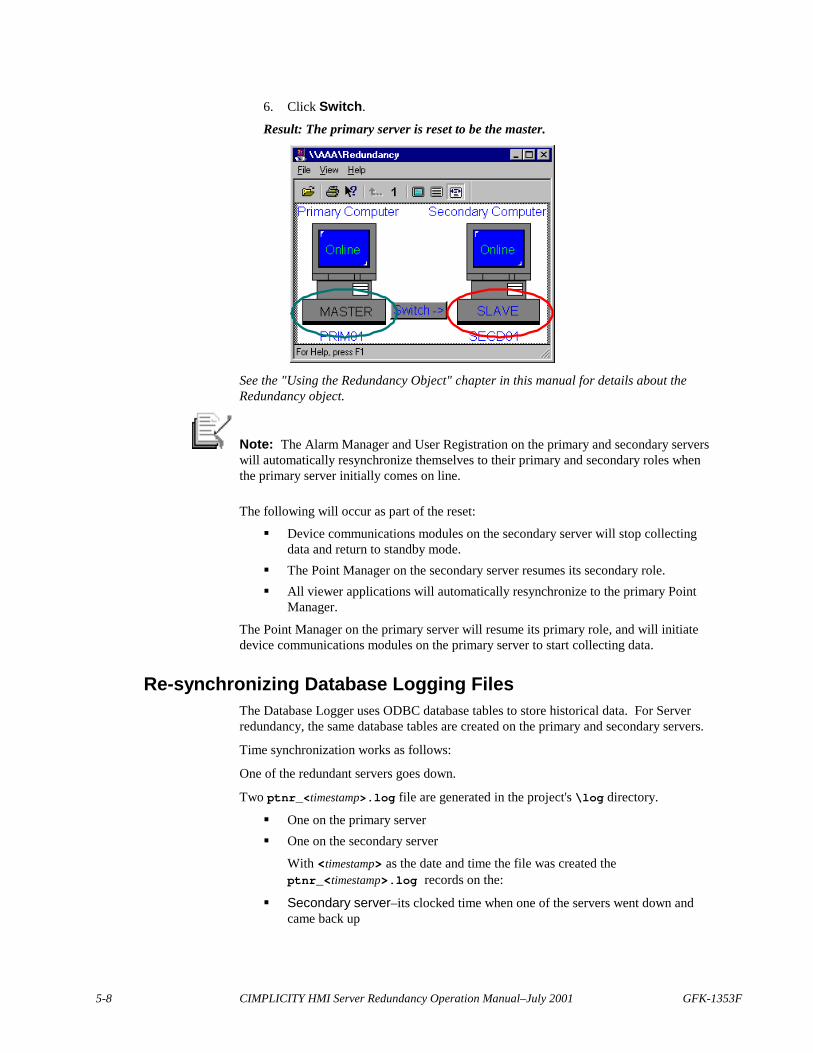
5-8 CIMPLICITY HMI Server Redundancy Operation Manual–July 2001 GFK-1353F
6. Click Switch.
Result: The primary server is reset to be the master.
See the "Using the Redundancy Object" chapter in this manual for details about theRedundancy object.
Note: The Alarm Manager and User Registration on the primary and secondary serverswill automatically resynchronize themselves to their primary and secondary roles whenthe primary server initially comes on line.
The following will occur as part of the reset:
� Device communications modules on the secondary server will stop collectingdata and return to standby mode.
� The Point Manager on the secondary server resumes its secondary role.� All viewer applications will automatically resynchronize to the primary Point
Manager.
The Point Manager on the primary server will resume its primary role, and will initiatedevice communications modules on the primary server to start collecting data.
Re-synchronizing Database Logging FilesThe Database Logger uses ODBC database tables to store historical data. For Serverredundancy, the same database tables are created on the primary and secondary servers.
Time synchronization works as follows:
One of the redundant servers goes down.
Two ptnr_<timestamp>.log file are generated in the project's \log directory.
� One on the primary server� One on the secondary server
With <timestamp> as the date and time the file was created theptnr_<timestamp>.log records on the:
� Secondary server–its clocked time when one of the servers went down andcame back up

GFK-1353F Recovery Procedures 5-9
� Primary server–its clocked time when one of the servers went down and cameback up
These files are then used to synchronize the databases.
To synchronize the databases on the primary and secondary nodes, on theprimary server:
1. Open the project's Workbench.2. Click the Tools menu.3. Select Command prompt.4. In the Command Prompt dialog box, type:
datamerge
5. (Optional) Run the datamerge.exe utility with optional parameters to mergespecific times. The command format is:datamerge.exe [[source] [dest] time1 time2]
where
the parameters are:
source Name of the source server
dest Name of the destination server
time1 Start time for merging data
time2 End time for merging data
Important: You can only run datamerge.exe on the primary server - that is, theserver that has all of the ODBC data sources defined. Therefore, the primary server has tobe running before you begin.
As it executes, the datamerge.exe utility:
1. Reads the ptnr_<timestamp>.log files on the primary and secondary servers.
2. Determines from the ptnr_<timestamp>.log files in the primary server's \logdirectory what data needs to be merged from the primary server's database to thesecondary server's database
3. Executes the merge from primary to secondary.4. Determines from the ptnr_<timestamp>.log files in the secondary server's
\log directory what data needs to be merged from the secondary server'sdatabase to the primary server's database
5. Executes the merge from secondary to primary.
A db_merge.log file is generated to report the success or failure of the merge.
Note: When you run the datamerge.exe utility with specific start and end times, theptnr_timestamp.log files on the secondary and primary servers are not used.
GE FANUC Parts
5-10 CIMPLICITY HMI Server Redundancy Operation Manual–July 2001 GFK-1353F
Failure Exceptions for Automatic Server RedundancyThere are two categories of failure exceptions that CIMPLICITY automatic ServerRedundancy will not handle:
� Process failures, and� Network failures.
Process FailuresA process failure occurs when a single process on a server fails. If this occurs on aprimary server, the recovery method depends on which process failed.
� If the Alarm Manager or User Registration on the primary server fails, controlautomatically passes the corresponding process on the secondary server. If theprocess on the primary server is restarted (via cpc), control will automaticallypass back to the process on the primary server.
� If a device communications process on the primary server fails, control will notpass to the corresponding process on the secondary server, and point data will belost.
� If the Point Manager on the primary server fails, control automatically passes tothe Point Manager on the secondary server.
To recover from process failure in automatic redundancy:1. Click Project on the Workbench menu bar.2. Select Stop to shut down the project on the primary server.3. Select Run to restart it.4. After the project is up and running, reset the primary server to be the master.
To circumvent limitations of process failure in automatic redundancy:Use either of two manual redundancy functions to anticipate and deal with this possibility.
See "CIMPLICITY Manual Server Redundancy" in this manual.

GFK-1353F Recovery Procedures 5-11
Network FailuresNetwork partition occurs when the computer network fails. Each CIMPLICITY servercontinues to perform its own functions, but there is no communications between theservers. Secondary servers will perform their automatic takeover procedures. In otherwords, both the primary and secondary servers act as master.
To make one server master when two are performing automatic takeover:1. On each secondary server, use Stop to shut down the CIMPLICITY HMI
project.2. Repair the network.3. After the network is restored, use Start to bring the project on the secondary
server back online.
Note: The above procedure assumes that the CIMPLICITY HMI project is still runningon the primary server. If the project has been shut down, then use the normal startupprocedures to restart the project on both the primary and secondary server.
GE FANUC Parts

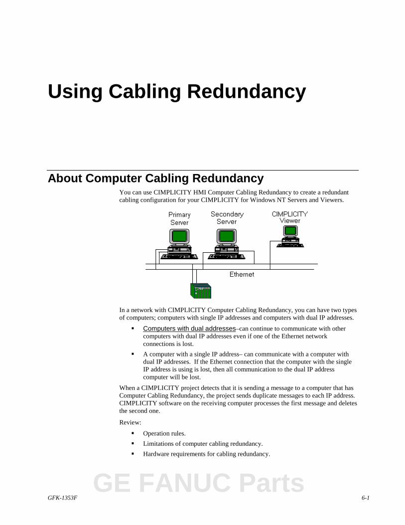
GFK-1353F 6-1
Using Cabling Redundancy
About Computer Cabling RedundancyYou can use CIMPLICITY HMI Computer Cabling Redundancy to create a redundantcabling configuration for your CIMPLICITY for Windows NT Servers and Viewers.
In a network with CIMPLICITY Computer Cabling Redundancy, you can have two typesof computers; computers with single IP addresses and computers with dual IP addresses.
� Computers with dual addresses–can continue to communicate with othercomputers with dual IP addresses even if one of the Ethernet networkconnections is lost.
� A computer with a single IP address– can communicate with a computer withdual IP addresses. If the Ethernet connection that the computer with the singleIP address is using is lost, then all communication to the dual IP addresscomputer will be lost.
When a CIMPLICITY project detects that it is sending a message to a computer that hasComputer Cabling Redundancy, the project sends duplicate messages to each IP address.CIMPLICITY software on the receiving computer processes the first message and deletesthe second one.
Review:
� Operation rules.� Limitations of computer cabling redundancy.� Hardware requirements for cabling redundancy.
GE FANUC Parts
6-2 CIMPLICITY HMI Server Redundancy Operation Manual–July 2001 GFK-1353F
Understanding Operation RulesThe following rules describe the overall operation of a computer with Computer CablingRedundancy:
� When a loss of a network is detected Ethernet traffic continues on the othernetwork.
� When the network is repaired the computers will re-establish communicationautomatically, within 45 seconds.
� If both networks are lost then CIMPLICITY HMI software acts as ifcommunication was lost to the project. CIMPLICITY HMI software will re-establish the connections to the other computer when the network is repaired.
Reviewing Limitations of Computer Cabling RedundancyThere are some limitations when using computer cabling redundancy that you need to beaware of bfore you implement it.
Functionality LimitsThe following functionality limitations apply for Computer Cabling Redundancy:
� If you are viewing logged data remotely with the Trend Control and the Ethernetcable that ODBC is currently using is lost then the Trend Control will stopupdating the logged data.
� If you are logging to a remote database and the Ethernet cable that ODBC iscurrently using is lost then some data may not be logged.
� Non-CIMPLICITY HMI applications might experience interruptions as they failover to the remaining Ethernet cable.
� It is not possible to have two Ethernet cards installed and only use one of themfor CIMPLICITY HMI software.
� The use of DHCP or DNS is not fully supported. You will need to add thenames and IP addresses of dual IP address computers into the cimhosts.txtfile.
Failure Recovery LimitationsCIMPLICITY Computer Cabling Redundancy will not cover the following failures:
� Loss of both network connections.� Rapid, alternating loss of both network connections, where the time period is
less than 45 seconds.
GFK-1353F Using Cabling Redundancy 6-3
Reviewing Hardware Requirements for Cabling RedundancyCIMPLICITY Computer Cabling Redundancy supports two network interface cards ineach computer.
Each card must be configured for a different
� IP network and� Physical Network
Different IP Networks for Cabling RedundancyThere are three different classes of IP Networks.
� A,� B and� C
If you configure one card for an A class IP network and the other for a C class, by defaultthey will be connected to different IP networks.
You can configure each card to the same class IP network. However, you have to makesure that they are, in fact, different IP networks.
ExampleYou have a Class C IP address 192.68.1.135.
Where
192.68.1 specifies the network that is a Class C status.
135 is a host (specific PC) in the network.
You can configure the second card with a Class C IP address by simply changing thenumber that is unique to the address.
The Class C IP address may now be 192.68.2.243.
Where
192.68.2 specifies a second network that is a Class C status.
243 is a host (specific PC) in the second network.
You now have two distinct IP networks.
Different Physical Networks for Cabling RedundancyEach of two network interface cards must be connected to its own physical network. Thisis needed to provide for a backup network in the case that one of the networks is lost.
GE FANUC Parts
6-4 CIMPLICITY HMI Server Redundancy Operation Manual–July 2001 GFK-1353F
Supported Network Configurations for CablingRedundancy
The supported network configurations are:
� Non-redundant server to non-redundant viewer.� Redundant server to non-redundant viewer.� Non-redundant server to redundant viewer.� Redundant server to redundant viewer.� Non-redundant server to non-redundant server.� Redundant server to redundant server.
Cabling Redundancy Configuration ProceduresOn each computer that will be using Computer Cabling Redundancy you will need to editthe cimhosts.txt file. This file resides in the etc directory below the HMI rootdirectory. There is a sample version of this file called cimhosts_sample.txt in theetc directory.
The cimhosts.txt file contains:
� The IP addresses of each computer that supports Computer CablingRedundancy.
� The failover period for detecting loss of connection.� The diagnostic output flag.� TCP/IP port use.
Use a text editor, such as Notepad, to edit the cimhosts.txt file.
Entering IP Addresses for Cabling RedundancyFor each computer that will be supporting CIMPLICITY HMI Computer CablingRedundancy you will need to enter all the IP addresses used by that computer.
The format for the cimhosts.txt file is:
<IP address> <hostname>
where
<IP address> is an IP address for a computer and <hostname> is the name of the computer.
ExampleA sample entry would be:3.26.5.5 alnt37
GFK-1353F Using Cabling Redundancy 6-5
Configuring Failover Rate for Cabling RedundancyThe default value for detecting that a network connection has been lost is 20 seconds.Due to the seamless nature of CIMPLICITY HMI Computer Cabling Redundancy, thisshould be a reasonable default. It can be modified, depending on the needs of theapplication. The loss detection rate should never be modified to less than 3 seconds.
The failover period is defined as:PING_INTERVAL * (PING_COUNT + 1)
The two parameters, PING_INTERVAL and PING_COUNT are defined in thecimhosts.txt file.
The formats for these parameters are:
#PING_INTERVAL <seconds>
#PING_COUNT <count>
where
<seconds> is the number of seconds between probe attempts and <count> is the number ofprobes to make.
ExampleSample entries for these parameters would be:#PING_INTERVAL 2
#PING_COUNT 10
A related parameter is CONNECT_TIMEOUT. This is the number of seconds to waitafter forming the TCP/IP connection for the initial data to arrive from the othercomputers. The default value is 10 seconds. There should be no reason to change thisvalue.
Generating Diagnostic Output for Cabling RedundancyThe CIMPLICITY HMI Computer Cabling Redundancy option can generate diagnosticoutput that you can use to track down problems with the functioning of the cablingredundancy system. To generate diagnostic output, enter a valid value for the DEBUGparameter in the cimhosts.txt file.
The format for this parameter is:
#DEBUG <flags>
where
<flags> is a value used to control what types of diagnostic output to generate.
You can add any of the following values together to form the <flags> value:
Value Output1 Print errors2 Print infrequent calls4 Print all Winsock calls8 Print all transactions
GE FANUC Parts

6-6 CIMPLICITY HMI Server Redundancy Operation Manual–July 2001 GFK-1353F
Using TCP/IP Port for Cabling RedundancyTo support CIMPLICITY HMI Computer Cabling Redundancy, you need to use a set ofTCP/IP ports in the range 5000 to 6000. Depending on other communication softwareyou are running you might have to alter this range. This is controlled by theSTART_PORT_RANGE and NUMBER_OF_PORTS parameters in the cimhosts.txt file.
The formats for these parameters are:
#START_PORT_RANGE <port>
#NUMBER_OF_PORTS <count>
where
<port> is the TCP/IP port to start with and <count> is the number of ports to use.
ExampleSample entries for these parameters would be:#START_PORT_RANGE 5000
#NUMBER_OF_PORTS 1000
GFK-1353F 7-1
Monitoring Network and SocketStatus
Computer Cabling Redundancy MonitoringThe Computer Cabling Redundancy Monitoring API allows you to determine how thenetwork connections at your site will be monitored. You can write BASIC scripts or Cprograms that can set points, generate alarms or pop up dialogs to inform the operatorthat a network connection has been lost. The following APIs are available: API
� The IP Status API can be used to monitor when a connection to an IP addresshas been lost or formed.
� The Socket Status API provides more detail about each of the connections in useby CIMPLICITY HMI.
Review:
� IP Status API.� IP Status API functions.
The APIs are callable from any programming language that can call exported C functionsfrom a DLL. This includes the CIMPLICITY BASIC Control Engine.
The functions reside in the redwinsock.dll DLL.
In the api\redundant_api directory under the CIMPLICITY HMI root directory aretwo samples programs that demonstrate the APIs.
� The BASIC script ip_status.bcl generates and resets alarms as IPconnections are lost or formed.
� The C program sock_status.cpp will print out the status information for allthe sockets currently in use.
In addition, a compiled version of the sock_status.cpp program is in the exedirectory.
Review:
� Socket Status API.� Socket Status API Functions.
GE FANUC Parts
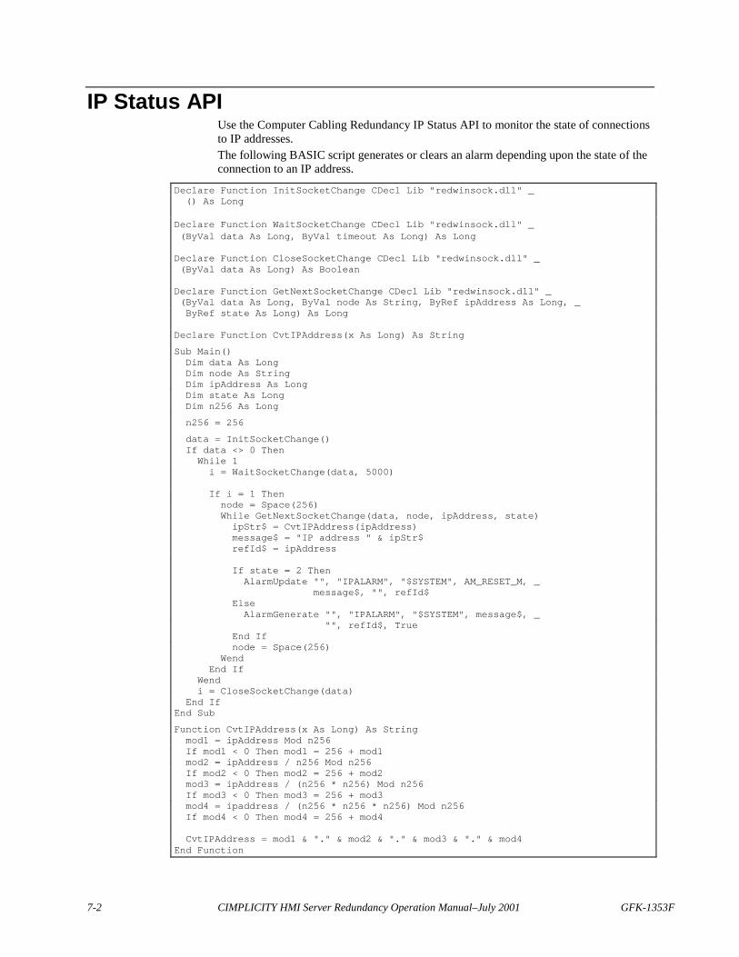
7-2 CIMPLICITY HMI Server Redundancy Operation Manual–July 2001 GFK-1353F
IP Status APIUse the Computer Cabling Redundancy IP Status API to monitor the state of connectionsto IP addresses.The following BASIC script generates or clears an alarm depending upon the state of theconnection to an IP address.
Declare Function InitSocketChange CDecl Lib "redwinsock.dll" _() As Long
Declare Function WaitSocketChange CDecl Lib "redwinsock.dll" _(ByVal data As Long, ByVal timeout As Long) As Long
Declare Function CloseSocketChange CDecl Lib "redwinsock.dll" _(ByVal data As Long) As Boolean
Declare Function GetNextSocketChange CDecl Lib "redwinsock.dll" _(ByVal data As Long, ByVal node As String, ByRef ipAddress As Long, _ByRef state As Long) As Long
Declare Function CvtIPAddress(x As Long) As String
Sub Main()Dim data As LongDim node As StringDim ipAddress As LongDim state As LongDim n256 As Long
n256 = 256
data = InitSocketChange()If data <> 0 ThenWhile 1i = WaitSocketChange(data, 5000)
If i = 1 Thennode = Space(256)While GetNextSocketChange(data, node, ipAddress, state)ipStr$ = CvtIPAddress(ipAddress)message$ = "IP address " & ipStr$refId$ = ipAddress
If state = 2 ThenAlarmUpdate "", "IPALARM", "$SYSTEM", AM_RESET_M, _
message$, "", refId$ElseAlarmGenerate "", "IPALARM", "$SYSTEM", message$, _
"", refId$, TrueEnd Ifnode = Space(256)
WendEnd If
Wendi = CloseSocketChange(data)
End IfEnd Sub
Function CvtIPAddress(x As Long) As Stringmod1 = ipAddress Mod n256If mod1 < 0 Then mod1 = 256 + mod1mod2 = ipAddress / n256 Mod n256If mod2 < 0 Then mod2 = 256 + mod2mod3 = ipAddress / (n256 * n256) Mod n256If mod3 < 0 Then mod3 = 256 + mod3mod4 = ipaddress / (n256 * n256 * n256) Mod n256If mod4 < 0 Then mod4 = 256 + mod4
CvtIPAddress = mod1 & "." & mod2 & "." & mod3 & "." & mod4End Function
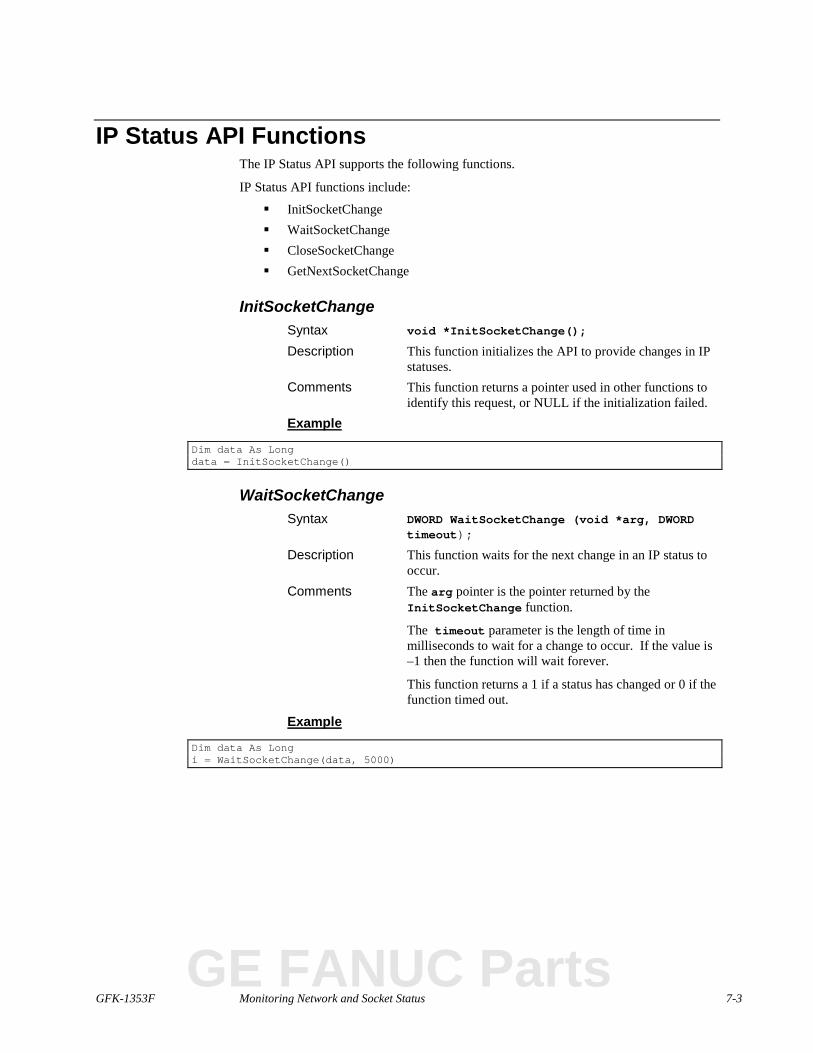
GFK-1353F Monitoring Network and Socket Status 7-3
IP Status API FunctionsThe IP Status API supports the following functions.
IP Status API functions include:
� InitSocketChange� WaitSocketChange� CloseSocketChange� GetNextSocketChange
InitSocketChangeSyntax void *InitSocketChange();
Description This function initializes the API to provide changes in IPstatuses.
Comments This function returns a pointer used in other functions toidentify this request, or NULL if the initialization failed.
Example
Dim data As Longdata = InitSocketChange()
WaitSocketChangeSyntax DWORD WaitSocketChange (void *arg, DWORD
timeout);
Description This function waits for the next change in an IP status tooccur.
Comments The arg pointer is the pointer returned by theInitSocketChange function.
The timeout parameter is the length of time inmilliseconds to wait for a change to occur. If the value is–1 then the function will wait forever.
This function returns a 1 if a status has changed or 0 if thefunction timed out.
Example
Dim data As Longi = WaitSocketChange(data, 5000)
GE FANUC Parts

7-4 CIMPLICITY HMI Server Redundancy Operation Manual–July 2001 GFK-1353F
CloseSocketChangeSyntax void CloseSocketChange (void *arg);
Description This function does a cleanup of the state changenotification.
Comments The arg pointer is the pointer returned by theInitSocketChange function.
This function does not have a return status.
Example
Dim data As Longi = CloseSocketChange(data)

GFK-1353F Monitoring Network and Socket Status 7-5
GetNextSocketChangeSyntax DWORD GetNextSocketChange (void *arg,
TCHAR *node,
DWORD *ipAddress,
DWORD *state);
Description This function gets the information about the next IP statuschange.
Comments The arg pointer is the pointer returned by theInitSocketChange function.
The node buffer is used to hold the name of the node forthis IP address. It should be 255 characters or larger.
The ipAddress is the IP address that has had a statuschange.
The state is the new state of the IP address. The statesare:
0 = Not connecting
1 = Connecting
2 = Connected
3 = Deleted
4 = Unknown
This function returns 1 if it is successful, or 0 if there areno more changes.
Example
Dim data As LongDim node As StringDim ipAddress As LongDim state As LongNode = Space(256)While GetNextSocketChange (data,node,ipAddress,state)Wend
GE FANUC Parts
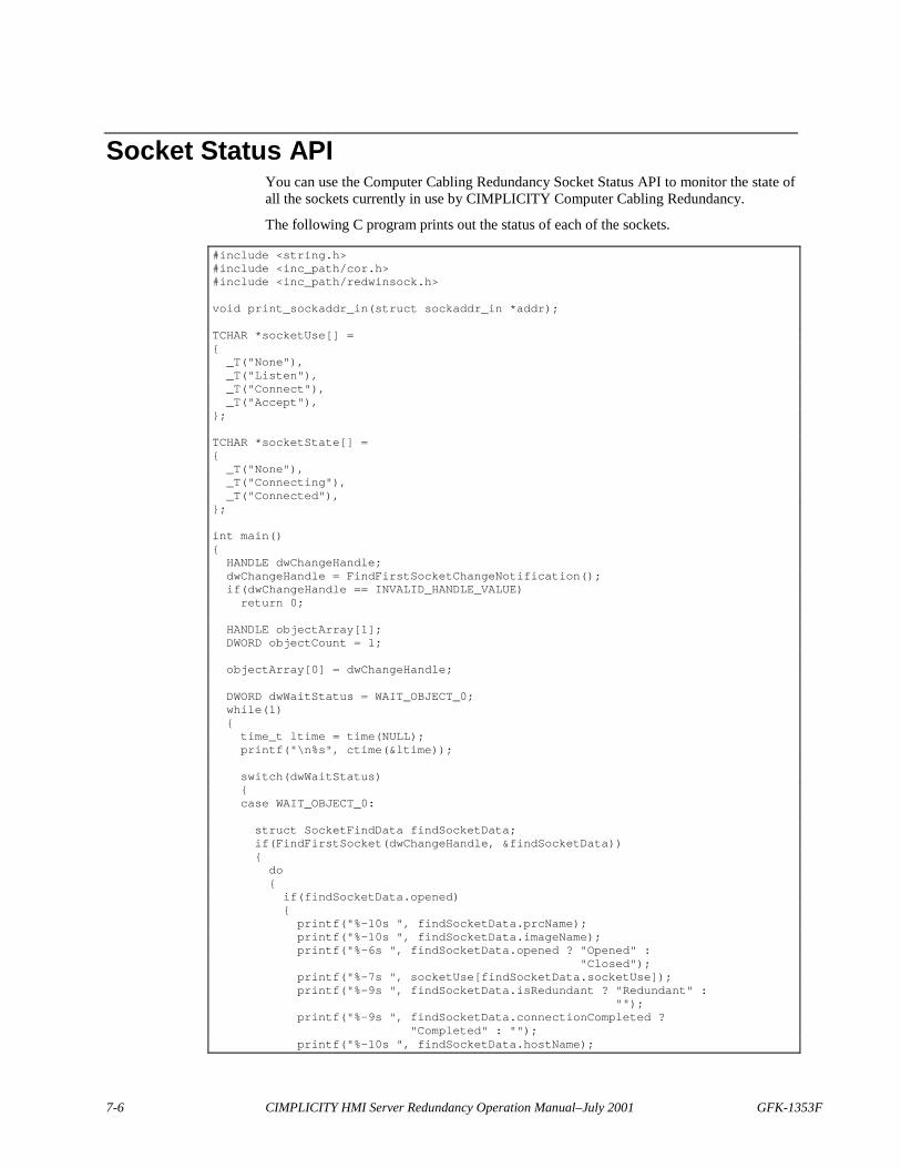
7-6 CIMPLICITY HMI Server Redundancy Operation Manual–July 2001 GFK-1353F
Socket Status APIYou can use the Computer Cabling Redundancy Socket Status API to monitor the state ofall the sockets currently in use by CIMPLICITY Computer Cabling Redundancy.
The following C program prints out the status of each of the sockets.
#include <string.h>#include <inc_path/cor.h>#include <inc_path/redwinsock.h>
void print_sockaddr_in(struct sockaddr_in *addr);
TCHAR *socketUse[] ={_T("None"),_T("Listen"),_T("Connect"),_T("Accept"),
};
TCHAR *socketState[] ={_T("None"),_T("Connecting"),_T("Connected"),
};
int main(){HANDLE dwChangeHandle;dwChangeHandle = FindFirstSocketChangeNotification();if(dwChangeHandle == INVALID_HANDLE_VALUE)return 0;
HANDLE objectArray[1];DWORD objectCount = 1;
objectArray[0] = dwChangeHandle;
DWORD dwWaitStatus = WAIT_OBJECT_0;while(1){time_t ltime = time(NULL);printf("\n%s", ctime(<ime));
switch(dwWaitStatus){case WAIT_OBJECT_0:
struct SocketFindData findSocketData;if(FindFirstSocket(dwChangeHandle, &findSocketData)){do{if(findSocketData.opened){printf("%-10s ", findSocketData.prcName);printf("%-10s ", findSocketData.imageName);printf("%-6s ", findSocketData.opened ? "Opened" :
"Closed");printf("%-7s ", socketUse[findSocketData.socketUse]);printf("%-9s ", findSocketData.isRedundant ? "Redundant" :
"");printf("%-9s ", findSocketData.connectionCompleted ?
"Completed" : "");printf("%-10s ", findSocketData.hostName);
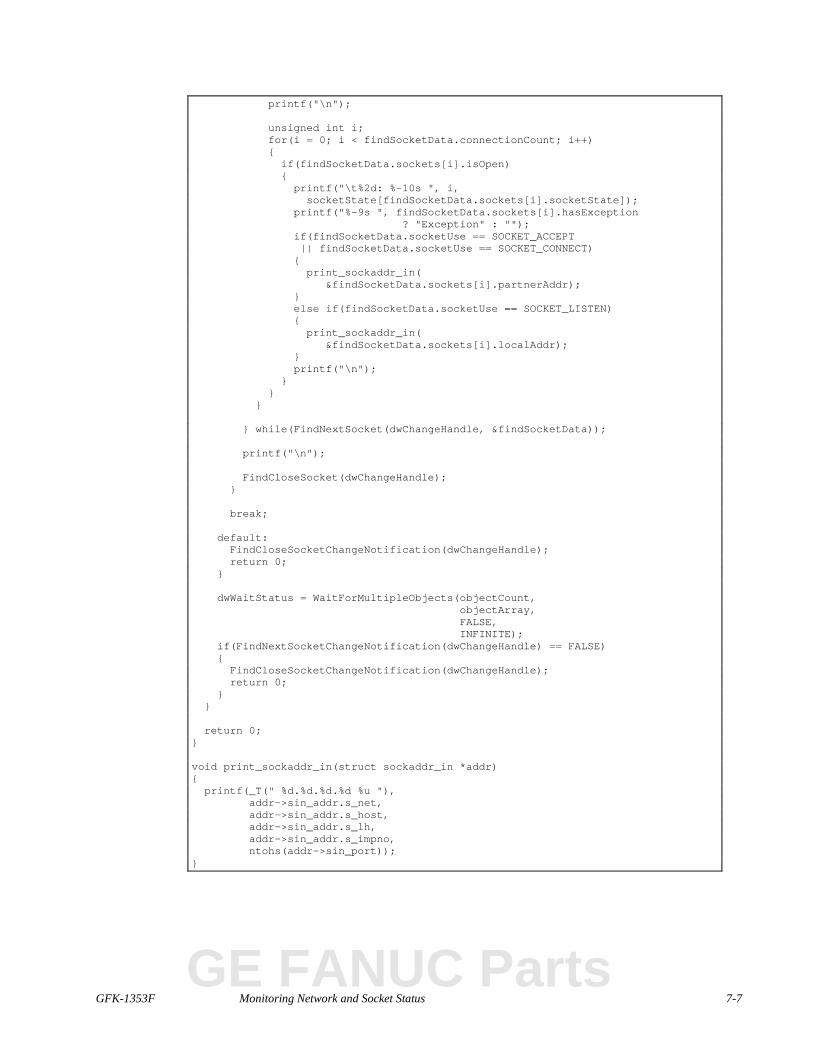
GFK-1353F Monitoring Network and Socket Status 7-7
printf("\n");
unsigned int i;for(i = 0; i < findSocketData.connectionCount; i++){if(findSocketData.sockets[i].isOpen){printf("\t%2d: %-10s ", i,socketState[findSocketData.sockets[i].socketState]);
printf("%-9s ", findSocketData.sockets[i].hasException? "Exception" : "");
if(findSocketData.socketUse == SOCKET_ACCEPT|| findSocketData.socketUse == SOCKET_CONNECT){print_sockaddr_in(
&findSocketData.sockets[i].partnerAddr);}else if(findSocketData.socketUse == SOCKET_LISTEN){print_sockaddr_in(
&findSocketData.sockets[i].localAddr);}printf("\n");
}}
}
} while(FindNextSocket(dwChangeHandle, &findSocketData));
printf("\n");
FindCloseSocket(dwChangeHandle);}
break;
default:FindCloseSocketChangeNotification(dwChangeHandle);return 0;
}
dwWaitStatus = WaitForMultipleObjects(objectCount,objectArray,FALSE,INFINITE);
if(FindNextSocketChangeNotification(dwChangeHandle) == FALSE){FindCloseSocketChangeNotification(dwChangeHandle);return 0;
}}
return 0;}
void print_sockaddr_in(struct sockaddr_in *addr){printf(_T(" %d.%d.%d.%d %u "),
addr->sin_addr.s_net,addr->sin_addr.s_host,addr->sin_addr.s_lh,addr->sin_addr.s_impno,ntohs(addr->sin_port));
}
GE FANUC Parts
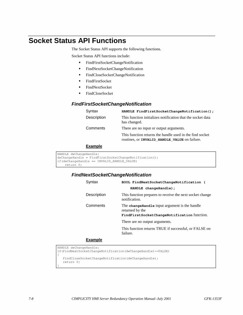
7-8 CIMPLICITY HMI Server Redundancy Operation Manual–July 2001 GFK-1353F
Socket Status API FunctionsThe Socket Status API supports the following functions.
Socket Status API functions include:
� FindFirstSocketChangeNotification� FindNextSocketChangeNotification� FindCloseSocketChangeNotification� FindFirstSocket� FindNextSocket� FindCloseSocket
FindFirstSocketChangeNotificationSyntax HANDLE FindFirstSocketChangeNotification();
Description This function initializes notification that the socket datahas changed.
Comments There are no input or output arguments.
This function returns the handle used in the find socketroutines, or INVALID_HANDLE_VALUE on failure.
Example
HANDLE dwChangeHandle;dwChangeHandle = FindFirstSocketChangeNotification();if(dwChangeHandle == INVALID_HANDLE_VALUE)
return 0;
FindNextSocketChangeNotificationSyntax BOOL FindNextSocketChangeNotification (
HANDLE changeHandle);
Description This function prepares to receive the next socket changenotification.
Comments The changeHandle input argument is the handlereturned by theFindFirstSocketChangeNotification function.
There are no output arguments.
This function returns TRUE if successful, or FALSE onfailure.
Example
HANDLE dwChangeHandle;if(FindNextSocketChangeNotification(dwChangeHandle)==FALSE){
FindCloseSocketChangeNotification(dwChangeHandle);return 0;
}
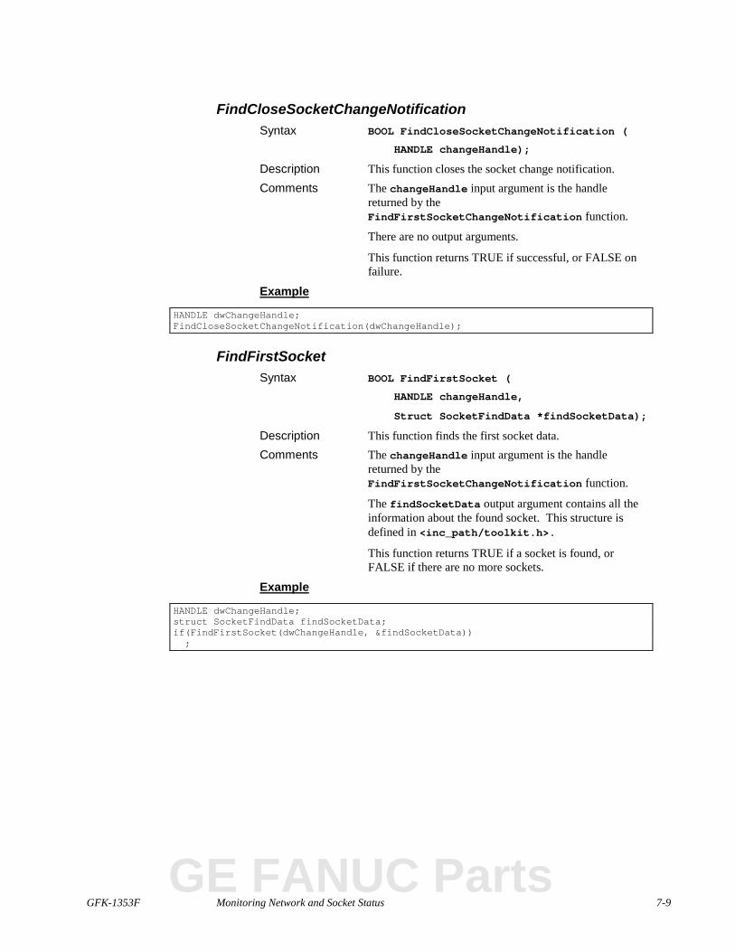
GFK-1353F Monitoring Network and Socket Status 7-9
FindCloseSocketChangeNotificationSyntax BOOL FindCloseSocketChangeNotification (
HANDLE changeHandle);
Description This function closes the socket change notification.Comments The changeHandle input argument is the handle
returned by theFindFirstSocketChangeNotification function.
There are no output arguments.
This function returns TRUE if successful, or FALSE onfailure.
Example
HANDLE dwChangeHandle;FindCloseSocketChangeNotification(dwChangeHandle);
FindFirstSocketSyntax BOOL FindFirstSocket (
HANDLE changeHandle,
Struct SocketFindData *findSocketData);
Description This function finds the first socket data.Comments The changeHandle input argument is the handle
returned by theFindFirstSocketChangeNotification function.
The findSocketData output argument contains all theinformation about the found socket. This structure isdefined in <inc_path/toolkit.h>.
This function returns TRUE if a socket is found, orFALSE if there are no more sockets.
Example
HANDLE dwChangeHandle;struct SocketFindData findSocketData;if(FindFirstSocket(dwChangeHandle, &findSocketData));
GE FANUC Parts
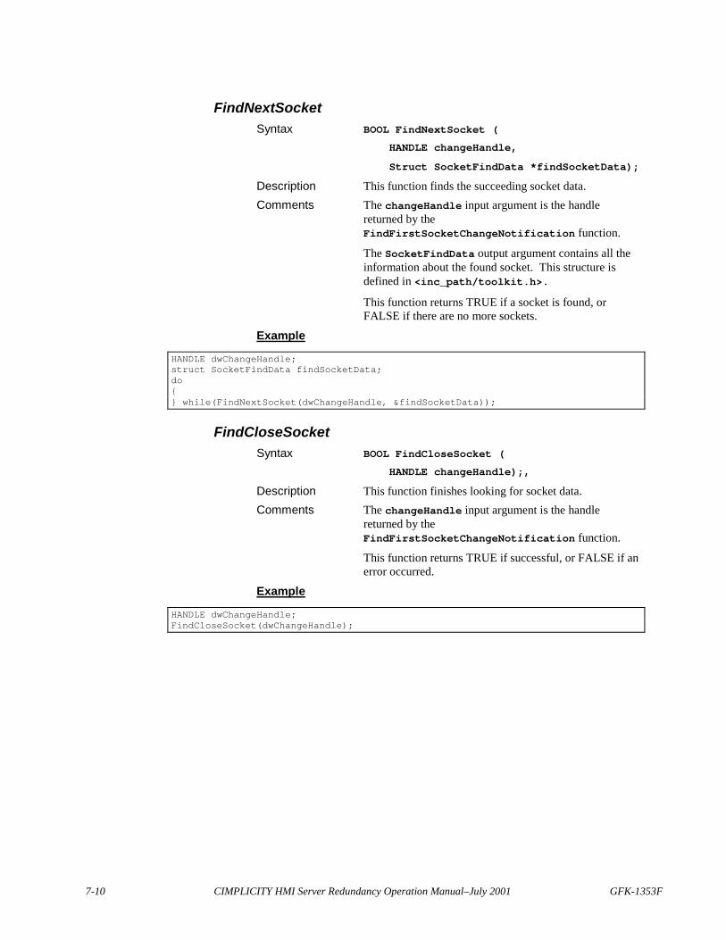
7-10 CIMPLICITY HMI Server Redundancy Operation Manual–July 2001 GFK-1353F
FindNextSocketSyntax BOOL FindNextSocket (
HANDLE changeHandle,
Struct SocketFindData *findSocketData);
Description This function finds the succeeding socket data.Comments The changeHandle input argument is the handle
returned by theFindFirstSocketChangeNotification function.
The SocketFindData output argument contains all theinformation about the found socket. This structure isdefined in <inc_path/toolkit.h>.
This function returns TRUE if a socket is found, orFALSE if there are no more sockets.
Example
HANDLE dwChangeHandle;struct SocketFindData findSocketData;do{} while(FindNextSocket(dwChangeHandle, &findSocketData));
FindCloseSocketSyntax BOOL FindCloseSocket (
HANDLE changeHandle);,
Description This function finishes looking for socket data.Comments The changeHandle input argument is the handle
returned by theFindFirstSocketChangeNotification function.
This function returns TRUE if successful, or FALSE if anerror occurred.
Example
HANDLE dwChangeHandle;FindCloseSocket(dwChangeHandle);
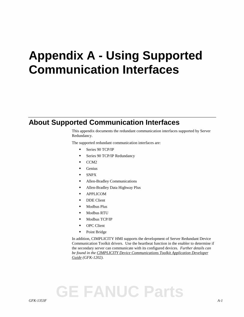
GFK-1353F A-1
Appendix A - Using SupportedCommunication Interfaces
About Supported Communication InterfacesThis appendix documents the redundant communication interfaces supported by ServerRedundancy.
The supported redundant communication interfaces are:
� Series 90 TCP/IP� Series 90 TCP/IP Redundancy� CCM2� Genius� SNPX� Allen-Bradley Communications� Allen-Bradley Data Highway Plus� APPLICOM� DDE Client� Modbus Plus� Modbus RTU� Modbus TCP/IP� OPC Client� Point Bridge
In addition, CIMPLICITY HMI supports the development of Server Redundant DeviceCommunication Toolkit drivers. Use the heartbeat function in the enabler to determine ifthe secondary server can communicate with its configured devices. Further details canbe found in the CIMPLICITY Device Communications Toolkit Application DeveloperGuide (GFK-1202).
GE FANUC Parts
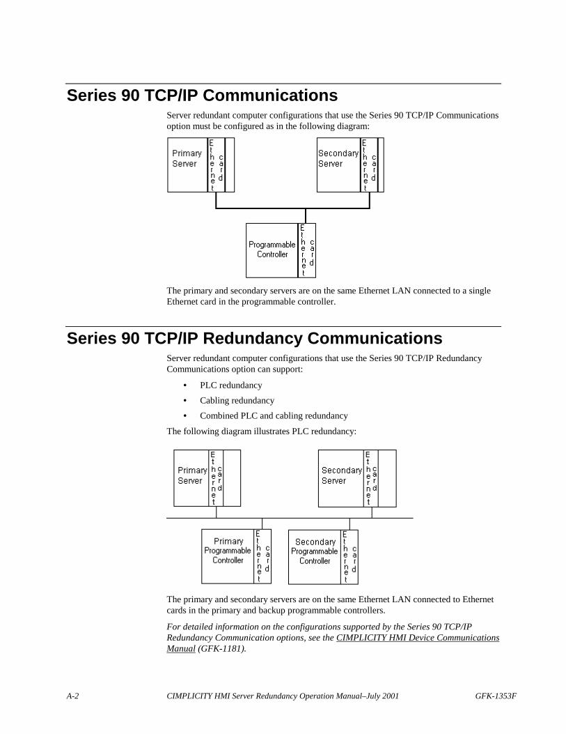
A-2 CIMPLICITY HMI Server Redundancy Operation Manual–July 2001 GFK-1353F
Series 90 TCP/IP CommunicationsServer redundant computer configurations that use the Series 90 TCP/IP Communicationsoption must be configured as in the following diagram:
The primary and secondary servers are on the same Ethernet LAN connected to a singleEthernet card in the programmable controller.
Series 90 TCP/IP Redundancy CommunicationsServer redundant computer configurations that use the Series 90 TCP/IP RedundancyCommunications option can support:
• PLC redundancy
• Cabling redundancy
• Combined PLC and cabling redundancy
The following diagram illustrates PLC redundancy:
The primary and secondary servers are on the same Ethernet LAN connected to Ethernetcards in the primary and backup programmable controllers.
For detailed information on the configurations supported by the Series 90 TCP/IPRedundancy Communication options, see the CIMPLICITY HMI Device CommunicationsManual (GFK-1181).
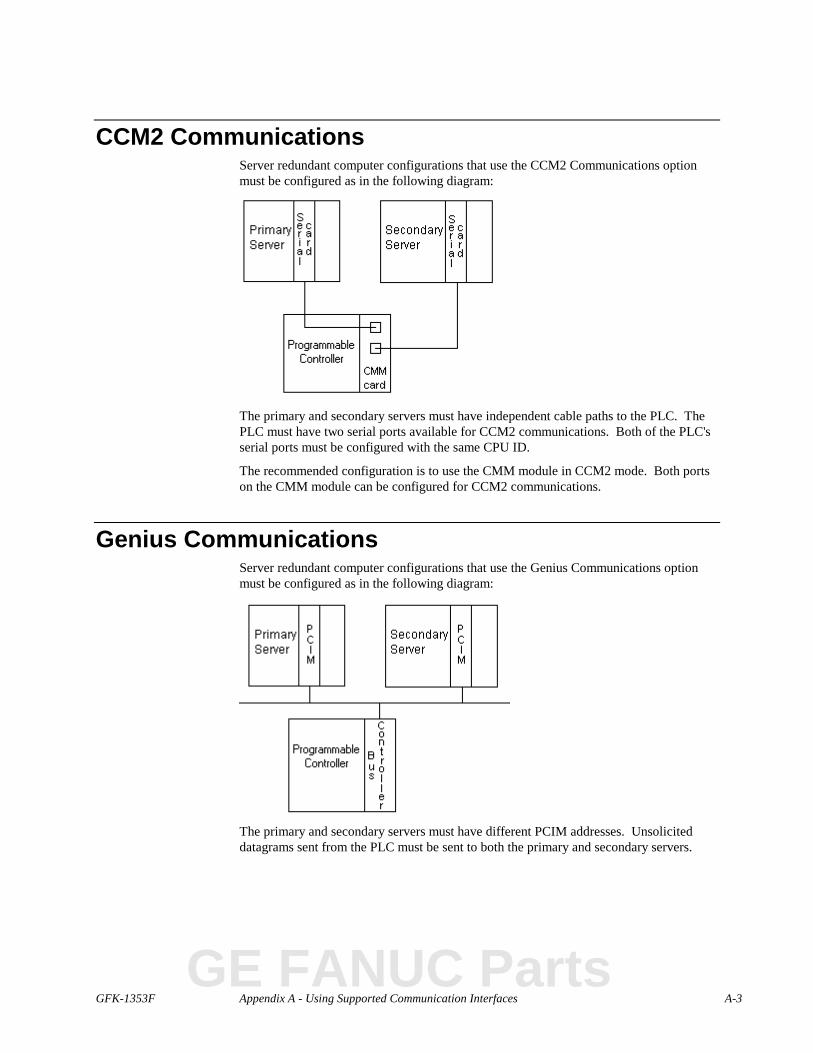
GFK-1353F Appendix A - Using Supported Communication Interfaces A-3
CCM2 CommunicationsServer redundant computer configurations that use the CCM2 Communications optionmust be configured as in the following diagram:
The primary and secondary servers must have independent cable paths to the PLC. ThePLC must have two serial ports available for CCM2 communications. Both of the PLC'sserial ports must be configured with the same CPU ID.
The recommended configuration is to use the CMM module in CCM2 mode. Both portson the CMM module can be configured for CCM2 communications.
Genius CommunicationsServer redundant computer configurations that use the Genius Communications optionmust be configured as in the following diagram:
The primary and secondary servers must have different PCIM addresses. Unsoliciteddatagrams sent from the PLC must be sent to both the primary and secondary servers.
GE FANUC Parts
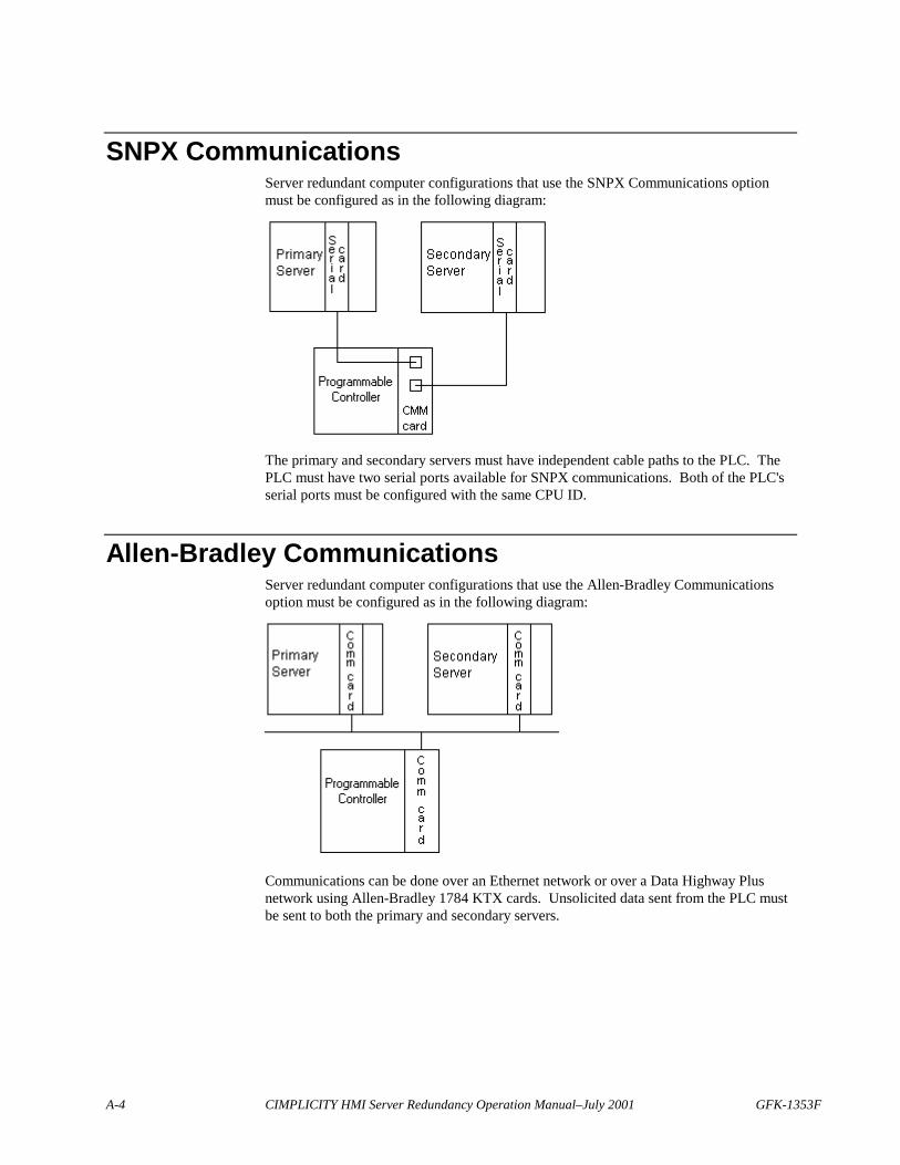
A-4 CIMPLICITY HMI Server Redundancy Operation Manual–July 2001 GFK-1353F
SNPX CommunicationsServer redundant computer configurations that use the SNPX Communications optionmust be configured as in the following diagram:
The primary and secondary servers must have independent cable paths to the PLC. ThePLC must have two serial ports available for SNPX communications. Both of the PLC'sserial ports must be configured with the same CPU ID.
Allen-Bradley CommunicationsServer redundant computer configurations that use the Allen-Bradley Communicationsoption must be configured as in the following diagram:
Communications can be done over an Ethernet network or over a Data Highway Plusnetwork using Allen-Bradley 1784 KTX cards. Unsolicited data sent from the PLC mustbe sent to both the primary and secondary servers.
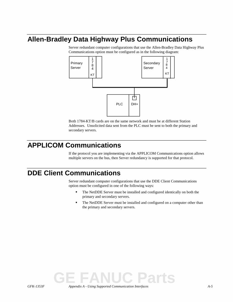
GFK-1353F Appendix A - Using Supported Communication Interfaces A-5
Allen-Bradley Data Highway Plus CommunicationsServer redundant computer configurations that use the Allen-Bradley Data Highway PlusCommunications option must be configured as in the following diagram:
Primary1784
PLC
KT
DH+
1784
KT
SecondaryServerServer
Both 1784-KT/B cards are on the same network and must be at different StationAddresses. Unsolicited data sent from the PLC must be sent to both the primary andsecondary servers.
APPLICOM CommunicationsIf the protocol you are implementing via the APPLICOM Communications option allowsmultiple servers on the bus, then Server redundancy is supported for that protocol.
DDE Client CommunicationsServer redundant computer configurations that use the DDE Client Communicationsoption must be configured in one of the following ways:
� The NetDDE Server must be installed and configured identically on both theprimary and secondary servers.
� The NetDDE Server must be installed and configured on a computer other thanthe primary and secondary servers.
GE FANUC Parts
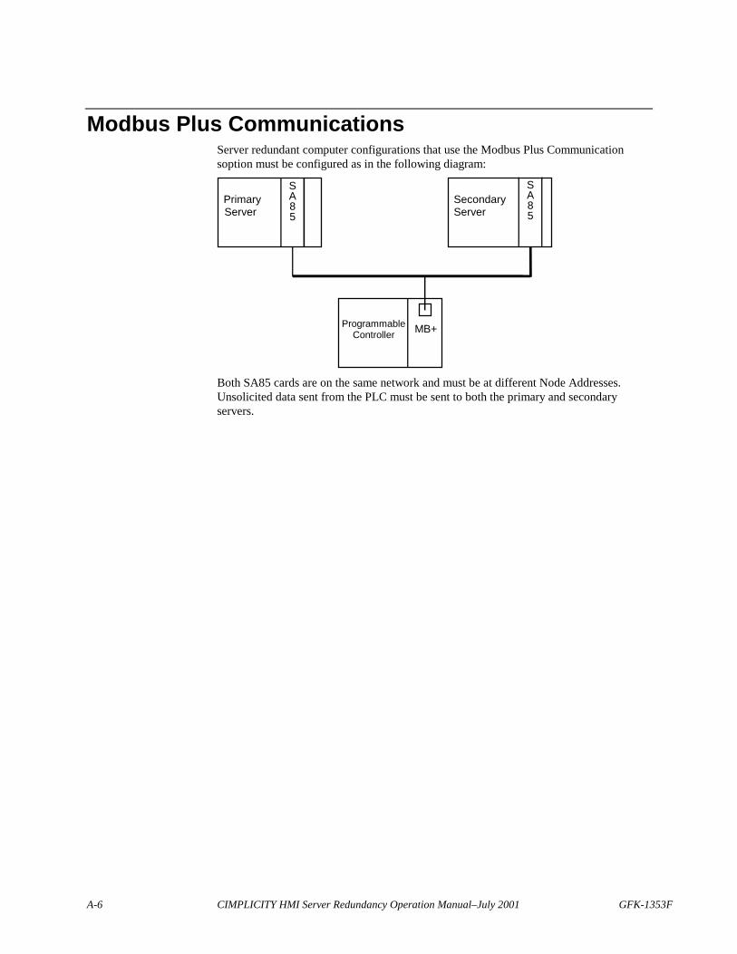
A-6 CIMPLICITY HMI Server Redundancy Operation Manual–July 2001 GFK-1353F
Modbus Plus CommunicationsServer redundant computer configurations that use the Modbus Plus Communicationsoption must be configured as in the following diagram:
PrimarySA85Server
SecondaryServer
ProgrammableController MB+
SA85
Both SA85 cards are on the same network and must be at different Node Addresses.Unsolicited data sent from the PLC must be sent to both the primary and secondaryservers.
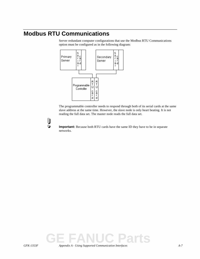
GFK-1353F Appendix A - Using Supported Communication Interfaces A-7
Modbus RTU CommunicationsServer redundant computer configurations that use the Modbus RTU Communicationsoption must be configured as in the following diagram:
The programmable controller needs to respond through both of its serial cards at the sameslave address at the same time. However, the slave node is only heart beating. It is notreading the full data set. The master node reads the full data set.
Important: Because both RTU cards have the same ID they have to be in separatenetworks.
GE FANUC Parts
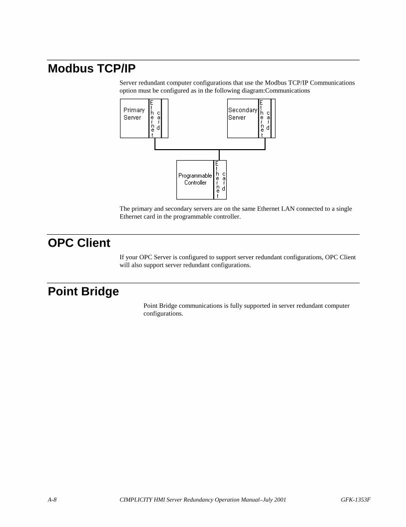
A-8 CIMPLICITY HMI Server Redundancy Operation Manual–July 2001 GFK-1353F
Modbus TCP/IPServer redundant computer configurations that use the Modbus TCP/IP Communicationsoption must be configured as in the following diagram:Communications
The primary and secondary servers are on the same Ethernet LAN connected to a singleEthernet card in the programmable controller.
OPC ClientIf your OPC Server is configured to support server redundant configurations, OPC Clientwill also support server redundant configurations.
Point BridgePoint Bridge communications is fully supported in server redundant computerconfigurations.
GFK-1353F B-1
Appendix B - ConfigurationParameters
About Server Redundancy Configuration ParametersServer redundancy configuration parameters cover:
� Failover rate configuration.� User registration synchronization.� Slave startup.
Failover Rate ConfigurationThe default value for the failover period is 15 seconds. It can be increased or decreased,depending on the needs of the application. The failover rate should never be modified toless than 3 seconds.
The failover period is defined as:REDUND_PROBE_DELAY * (REDUND_PROBE_COUNT + 1)
The two parameters, REDUND_PROBE_DELAY and REDUND_PROBE_COUNT are defined inthe global parameters file.
The formats for these parameters are:
REDUND_PROBE_DELAY|3|<millisec>
REDUND_PROBE_COUNT|3|<count>
where
<millisec> is the number of milliseconds for the probe delay and <count> is thenumber of probes to make.
Sample entries for these parameters would be:REDUND_PROBE_DELAY|3|1000
REDUND_PROBE_COUNT|3|3
A related parameter is REDUND_PROBE_PORT. This is the TCP/IP port number used toimplement the probing mechanism. The default value is 4000. Only change thisparameter if it conflicts with other software.
To make these changes go to the Workbench for the project and activate a commandprompt. Perform the following steps:
GE FANUC Parts
B-2 CIMPLICITY HMI Server Redundancy Operation Manual–July 2001 GFK-1353F
1. Type Cd master
2. Type Idtpop glb_parms
3. Type Notepad glb_parms.idt
4. Add or modify the above two parameters.5. Type Scpop glb_parms
6. Stop and Restart the project.
User Registration SynchronizationThe User Registration(UR) processes on the primary and secondary nodes need tosynchronize with each other at startup. This can normally occur within a 30-secondperiod. On slower computers this might not be enough time. The global parameterREDUND_LINK_SLEEP can be changed to provide more time for the UR process tosynchronize.
The format for this parameter is:REDUND_LINK_SLEEP|3|<time>
where
<time> is the sleep time in seconds.
For example, to set the sleep time to 30 seconds, enter the following in the globalparameters file:
REDUND_LINK_SLEEP|3|30
Slave StartupIf the project on both the primary (master) and secondary (slave) servers is configured tostart at boot, you can use the SLAVE_STARTUP_TIMEOUT global parameter to delaystarting the project on the secondary server until after the project on the primary serverstarts. This helps avoid race conditions between the two servers when they are trying todetermine which server is the master.Timeout.
If you do not define this global parameter, the default time is 0 (zero) minutes.
The format for this parameter is:SLAVE_STARTUP_TIMEOUT|1|<time>
where
<time> is the time in minutes to wait before starting the project on the secondaryserver.
For example, to delay the project startup on the secondary server by 2 minutes, enter thefollowing in the global parameters file:
SLAVE_STARTUP_TIMEOUT|1|2

GFK-1353F C-1
Appendix C - Computer CablingRedundancy Status LogMessages
Error MessagesThe following is a list of errors you may encounter in the CIMPLICITY Status Logrelating to Computer Cabling Redundancy.
Error messages cover:
� Binding failures.� Connection failures.� Socket failures.� Missed communications.
Binding FailuresThis error should only occur if a non-CIMPLICITY HMI communication program isusing IP ports in the same range as the Computer Cabling Redundancy option.
Failed to bind to port
CIMPLICITY HMI attempts to use the same IP port on both network interface cards(NIC). If this error occurs try changing the range of IP ports that Computer CablingRedundancy is using. See the section on TCP/IP Port Use in chapter 6.
GE FANUC Parts
C-2 CIMPLICITY HMI Server Redundancy Operation Manual–July 2001 GFK-1353F
Connection FailuresThese errors occur when the Computer Cabling Redundancy option starts a connectionwith another computer:
Failed to receive connection ID: invalid ID
Failed to complete connection: <IP Address>
Failed to receive connection ID: invalid ID
Failed to receive connection ID: timeout
Failed to receive connection ID: exception
Failed to receive connection ID: recv failed
When the option starts a connection with another computer it exchanges some identifyinginformation. If this information is not received, the connection will fail.
This is typically caused by an incorrect configuration. If the local computer believes thatthe remote computer is supporting Computer Cabling Redundancy but the remotecomputer is not configured for Computer Cabling Redundancy, then this error will occur.This error can also occur if the network is broken during the connection setup time.
Socket FailuresThis error occurs when the local socket is waiting for data:
Error performing select on socket
This error should never occur.
Missed CommunicationsThis error occurs when network traffic is not being received from the remote computer:
Missed hearing from partner: < IP Address>
If this error occurs and the network is functioning you should check the PING_INTERVALand PING_COUNT parameters in the cimhosts.txt file. You may need to increase themdepending on the load on your computers or network.
GFK-1353F D-1
Appendix D - TroubleshootingDatabase Merging
Problems and Solutions
Important: Check your db_merge.log file for error, after running a datamerge. In thetable below, you will find some solutions to common problems..
Following are some common problems that you can encounter while using DataMerge;the symptoms that alert you to them and solutions that you can use to correct them
Problem Not Running the DataMerge from Command Prompt windowcreated by Workbench
Symptoms WARNING:Unable to translateSITE_ROOT.dlrp_init_merge
Fri Apr 10 13:25:47 1998 failure 189 <No Prname>dlrp_init_table 93
Error 2 from fio file data_field: No such fileor directory
Error of type COR_SC_ERR:source 130 code 2COR_logstatus FATAL error resulting in exit
Solution Do the following:1. Open the project's Workbench.2. Click Tools on the menu bar.3. Select Command prompt…
Type datamerge.exe in the Command Prompt window.
GE FANUC Parts
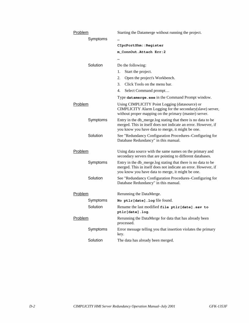
D-2 CIMPLICITY HMI Server Redundancy Operation Manual–July 2001 GFK-1353F
Problem Starting the Datamerge without running the project.Symptoms …
CIpcPortShm::Register
m_ConnOut.Attach Err:2
…
Solution Do the following:1. Start the project.2. Open the project's Workbench.3. Click Tools on the menu bar.4. Select Command prompt…
Type datamerge.exe in the Command Prompt window.
Problem Using CIMPLICITY Point Logging (datasource) orCIMPLICITY Alarm Logging for the secondary(slave) server,without proper mapping on the primary (master) server.
Symptoms Entry in the db_merge.log stating that there is no data to bemerged. This in itself does not indicate an error. However, ifyou know you have data to merge, it might be one.
Solution See "Redundancy Configuration Procedures–Configuring forDatabase Redundancy" in this manual.
Problem Using data source with the same names on the primary andsecondary servers that are pointing to different databases.
Symptoms Entry in the db_merge.log stating that there is no data to bemerged. This in itself does not indicate an error. However, ifyou know you have data to merge, it might be one.
Solution See "Redundancy Configuration Procedures–Configuring forDatabase Redundancy" in this manual.
Problem Rerunning the DataMerge.Symptoms No ptlr[date].log file found.Solution Rename the last modified file ptlr[date].sav to
ptlr[date].log.Problem Rerunning the DataMerge for data that has already been
processed.Symptoms Error message telling you that insertion violates the primary
key.Solution The data has already been merged.
GFK-1353F Index-i
Index
AAbout
Computer Cabling Redundancy 6-1Supported communication interfaces for Server
redundancy A-1
2-13Alarm Management
Operation during failover 5-5Redundant system behavior 2-14
Allen-Bradley CommunicationsRedundant configuration A-4
Allen-Bradley Data Highway PlusRedundant configuration A-5Scripting requirements for server redundancy 2-4
ApplicationsDatabase logging requirements for server
redundancy 2-4Network configuration requirements for server
redundancy 2-5Primary and secondary computer requirements for
server redundancy 2-4Time synchronization requirements for server
redundancy 2-5APPLICOM
Redundant configuration A-5Automatic Redundancy
Introduction 2-6Recover from process failure 5-10
BBase System
Order of configuration 3-1Boot
Configuring the project to start at 5-4
CCabling Redundancy 1-3Cause
Detecting for primary server failure 5-6CCM2
Redundant configuration A-3cimhosts.txt
Computer cabling redundancy 6-4IP addresses 6-4
Cimhosts.txtDEBUG flag 6-5Number_of_ports 6-6Start_port_range 6-6Redundant system behavior 2-14
CloseSocketChange 7-4Computer
Requirements for server redundancy 2-2Computer cabling redundancy
Error messages and missed communications C-2Monitoring API 7-1
Computer Cabling RedundancyAbout 6-1Configuration 6-4Definition for CIMPLICITY HMI 1-5Diagnostic output 6-5Error messages and connection failures C-2Error messages and socket failures C-2Failover rate configuration 6-5Failure recovery limitations 6-2Functionality Limitations 6-2Hardware requriements 6-3IP status API 7-2Rules of operation 6-2Socket status API 7-6Supported network configurations 6-4TCP/IP port use 6-6
Computer Network Redundancy 1-4Computers
In server redundancy 2-6Configuration
Computer cabling redundancy 6-4Database logging 3-6Order of in base system 3-1Server redundancy procedures 3-1
Connect_Timeout 6-5Connection Failures
Error messages and computer cabling redundancy C-2
GE FANUC Parts
Index-ii CIMPLICITY HMI Server Redundancy Operation Manual–July 2001 GFK-1353F
DData Collection
Redundant system behavior 2-9Database Logging
Configuration 3-6Requirements for server redundancy 2-4Resynchronizing files in server redundancy 5-8
Datamerge.exe 5-9DDE Client
Redundant configuration A-5Definition
Primary server 2-6Secondary Server 2-6
DetectCause for primary server failure 5-6
Devcom ConfigurationServer redundancy 3-5
Device CommunicationsOperation during failover 5-5
Diagnostic OutputComputer cabling redundancy 6-5
EError Messages
Computer cabling redundancy and Bindingfailures C-1
Computer cabling redundancy and connectionfailures C-2
Computer cabling redundancy and missedcommunications C-2
Computer cabling redundancy, Socket failures C-2
FFailover
Alarm management operation during 5-5Automatic-overview 2-7Device communications operation during 5-5Point management operation during 5-5Runtime interfaces during 5-6 2-14Server Redundancy 2-14System operation during 5-5User logons operation during 5-6
Failover Rate ConfigurationComputer cabling redundancy 6-5Server redundancy B-1
FailureDetecting cause on primary server 5-6Network failure exceptions 5-11Process failure exceptions 5-10
Failure ExceptionsServer redundancy 5-10
2-9Failure recovery Limitations
Server redundancy 2-9Failure Recovery Limitations
Computer cabling redundancy 6-2FindCloseSocket 7-10FindCloseSocketChangeNotification 7-9FindFirstSocket 7-9FindFirstSocketChangeNotification 7-8FindNextSocket 7-10FindNextSocketChangeNotification 7-8Functionality Limitations
Computer cabling redundancy 6-2Server redundancy 2-8
FunctionsIP status API 7-3Socket status API 7-8
GGenius
Redundant Configuration A-3GetNextSocketChange 7-5Global Point
Server redundancy configuration 3-5
HHardware
Computer requirements for server redundancy 2-2Network requirements for server redundancy 2-2
Hardware requirementsServer redundancy 2-1
Hardware RequirementsComputer cabling redundancy 6-3
IInitSocketChange 7-3Integration
Redundant features 2-6Introduction
Server redundancy 2-6IP Addresses
cimhosts.txt 6-4IP Status API 7-1, 7-2
CloseSocketChange 7-4Functions 7-3GetNextSocketChange 7-5InitSocketChange 7-3WaitSocketChange 7-3
GFK-1353F Index Index-iii
LLimitations
Circumvent in automatic redundancy 5-10Computer cabling redundancy functionality 6-2
Limitations Failure RecoveryComputer cabling redundancy 6-2
MManual Redundancy
Introduction 2-6Map Drive
Requirement for redundancy 2-4Missed Communications
Error messages and computer cabling redundancy C-2Modbus RTU
Redundant configuration A-7Modbus TCP/IP
Redundant configuration A-8Modubs Plus
Redundant configuration A-6Monitoring API
Computer cabling redundancy 7-1
NNetwork
Configuration requirements for server redundancy 2-5Requirements for server redundancy 2-2Server redundancy failures 5-11
Network ConfigurationServer redundancy 3-3
Normal operating proceduresServer redundancy 5-1
Normal Operating Procedures Startup and ShutdownServer redundancy 5-1
Number_of_Ports 6-6
OOverview
Before you start 2-1
PPing_Count 6-5Ping_Interval 6-5PLC Redundancy 1-3Point Bridge
Redundant configuration A-8Point Management
Operation during failover 5-5
PrimarySysnchronize databases on the primary and secondary
nodes 5-9Primary and Secondary Computers
Requirements for server redundancy 2-4Primary Computer
Mapped drive requirement in redundancy 2-4Primary Server
Automatic failover overview 2-7Definition 2-6Failover return overview 2-7Reset after recovery, Server redundancy 5-7
PrivilegesRequired for mapping a slave drive 2-7
ProblemsDatabase merging D-1
ProceduresServer redundancy 3-1
Process FailuresServer redundancy 5-10
ProjectConfiguration in server redundancy 3-2Configure project to start at boot 5-4Start a redundant project 5-2Start from a secondary server 5-3Stop a redundant project 5-3
Project FailoverAutomatic-overview 2-7
RREDUND_LINK_SLEEP B-2REDUND_PROBE_DELAY B-1REDUND_PROBE_INTERVAL B-1Redundancy
Cabling 1-3General definition 1-2Host Computer network 1-4PLC 1-3Server 1-4
Redundant configurationAllen-Bradley communications A-4Allen-Bradley Data Highway Plus A-5
GE FANUC Parts

Index-iv CIMPLICITY HMI Server Redundancy Operation Manual–July 2001 GFK-1353F
Redundant ConfigurationAPPLICOM A-5CCM2 A-3DDE client A-5Genius A-3Modbus Plus A-6Modbus RTU A-7Modbus TCP/IP A-8Point bridge A-8Series 90 TCP/IP A-2Series 90 TCP/IP redundancy A-2SNPX A-4
Redundant System BehaviorAlarm management 2-14CimView 2-14Data collection 2-9Setpoints 2-12
RequirementMapped drive in redundancy 2-4
RequirementsUser privileges for mapping a drive 2-7
Requirements for Server RedundancyApplication 2-4Computer 2-2Database logging 2-4Network 2-2Network configuration 2-5Scripting 2-4Time synchronization 2-5Use of primary/secondary computers 2-4
ResetAfter automatic failover 2-7Primary server after recovery 5-7
Re-synchronizeDatabase logging files 5-8
Rules of OperationComputer cabling redundancy 6-2
Runtime InterfacesOperation during failover 5-6
SScripting
Requirements for server redundancy 2-4Secondary
Synchronzie databases on the primary and secondarynodes 5-9
Secondary ComputerMapped drive requirement in redundancy 2-4
Secondary ServerAutomatic failover overview 2-7Definition 2-6Failover return overview 2-7Starting a project from 5-3
Series 90 TCP/IP
Redundant configuration A-2Series 90 TCP/IP redundancy
Redundant configuration A-2Server redundancy
Hardware requirements 2-1Server Redundancy 1-4
Allen-Bradley communications A-4Allen-Bradley Data Highway Plus A-5APPLICOM A-5CCM2 A-3Configuration procedures 3-1DDE client A-5Definition for CIMPLICITY HMI 1-5Devcom configuration 3-5Failover 2-14Failover rate configuration B-1Failure Recover Limitations 2-9Functionality limitations 2-8Genius A-3Global point configuration 3-5Modbus Plus A-6Modbus RTU A-7Modbus TCP/IP A-8Network configuration 3-3Network failures 5-11Normal operating procedures 5-1Point bridge A-8Process failures 5-10Resetting primary server after recovery 5-7Resynchronizing database logging files 5-8Series 90 TCP/IP A-2Series 90 TCP/IP redundancy A-2Slave startup timeout B-2SNPX A-4Supported communication interfaces, About A-1User registration synchronization B-2
Server Redundancy Failure Exceptions 5-10Server Redundancy System Operation During
Failover 5-5Server RedundancyNormal startup and shutdown 5-1
Redundant system behavior 2-12Slave Startup Timeout
Server redundancy B-2SLAVE_STARTUP_TIMEOUT B-2SNPX
Redundant configuration A-4Socket failures
Error Messages and computer cabling redundancy C-2

GFK-1353F Index Index-v
Socket Status API 7-1, 7-6FindCloseSocket 7-10FindCloseSocketChangeNotification 7-9FindFirstSocket 7-9FindFirstSocketChangeNotification 7-8FindNextSocket 7-10FindNextSocketChangeNotification 7-8Functions 7-8
SolutionsDatabase merging D-1
StartA project from a secondary server 5-3Redundant project 5-2
Start_Port_Range 6-6Stop
A redundant project 5-3Supported Network Configurations
Computer cabling redundancy 6-4System Operation During Failover
Server redundancy 5-5
TTCP/IP Port Use
Computer cabling redundancy 6-6Time Synchronization
Requirements for server redundancy 2-5
UUser
Requirements for mapping a drive 2-7User Logons
Operation during failover 5-6
Redundant system behavior 2-14 2-14
User Registration SynchronizationServer redundancy B-2
WWaitSocketChange 7-3
GE FANUC Parts


