23
GE imagination at work GE Industrial 40.5kV Vacuum Circuit Breaker & Medium Voltage Metal-Clad Switchgear
GE imagination at work
GEIndustrial
40.5kV Vacuum Circuit Breaker & Medium Voltage Metal-Clad Switchgear

More Than 80 Years of Interrupter Experience
GE pioneered experimental vacuum interrupters in the 1920's. Refined it and introduced the world's first vacuum interrupter distribution breaker in the 1960's. To date, this interrupter design has been the world leader in vacuum technology and has accumulated over 45 years of reliable field service.
World Class Quality
Manufactured, assembled and tested all in the same sophisticated facility, SecoVac is the product of state of the art manufacturing processes assured by ISO 9001:2000 and ISO14001 certification. Precision tooled parts, computer aided design and advanced production techniques, as well as the protection of the "E Coat" (cathodic electrocoating) paint process have resulted in a standard of excellence unmatched in the industry.
Universal Applications
SecoVac is designed, assembled and tested to meet or exceed applicable IEC, GB and DL standards. It is suitable for applications in all major industries including T & D, Oil & Gas, Automotive, Processing Plants, Iron and Steel mill, Mining, Commercial Buildings, etc.
It provides protection for all types of applications: cable, overhead lines, motors, capacitors, transformers, busbar sections, etc.
Environment Conscious
Selecting low environmental impact technologies has become increasingly important to engineers tasked with choosing equipment for an application. With commitment to environment protection, the solid insulation of epoxy resin is used for SecoVac series MV embedded pole vacuum circuit breaker instead of SF6 gas.
GE imagination at work
Predominant Vacuum Technology
1
Vacuum switching technology is nowadays the dominant switching principle in medium voltage. Innovative developments are leading to a continuously increasing market growth, based on the fundamental advantages such as reliability, availability, compactness and, last but not least, the environmental responsibility of the vacuum as a switching medium.
Vacuum Interrupter
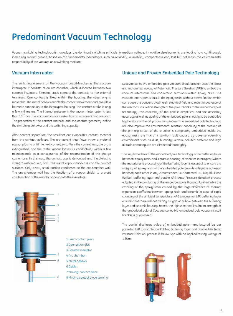
The switching element of the vacuum circuit-breaker is the vacuum interrupter. It consists of an arc chamber, which is located between two ceramic insulators. Terminal studs connect the contacts to the external terminals. One contact is fixed within the housing, the other one is moveable. The metal bellows enable the contact movement and provide a hermetic connection to the interrupter housing. The contact stroke is only a few millimeters. The internal pressure in the vacuum interrupter is less than 10-7 bar. The vacuum circuit-breaker has no arc-quenching medium. The properties of the contact material and the contact geometry define the switching behavior and the switching capacity.
After contact separation, the resultant arc evaporates contact material from the contact surfaces. The arc current thus flows throw a material vapour plasma until the next current zero. Near the current zero, the arc is extinguished, and the metal vapour looses its conductivity within a few microseconds as a consequence of the recombination of the charge carrier ions. In this way, the contact gap is de-ionized and the dielectric strength restored very fast. The metal vapour condenses on the contact surfaces. Only a very small portion condenses on the arc chamber wall. The arc chamber wall has the function of a vapour shield, to prevent condensation of the metallic vapour onto the insulators.
2
4
1
37
5
6
8
1 Fixed contact piece
2 Connection disc
3 Ceramic insulator
4 Arc chamber
5 Metal bellows
6 Guide
7 Moving contact piece
8 Moving contact piece terminal
Unique and Proven Embedded Pole Technology
SecoVac series MV embedded pole vacuum circuit breaker uses the latest and mature technology of Automatic Pressure Gelation (APG) to embed the vacuum interrupter and connection terminals within epoxy resin. The vacuum interrupter is cast in the epoxy resin, without screw fixation which can cause the concentrated harsh electrical field and result in decrease of the electrical insulation strength of the pole. Thanks to the embedded pole technology, the assembly of the pole is simplified, and the assembly accuracy as well as quality of the embedded pole is easily to be controlled by the state of the art production process. The embedded pole technology will also improve the environmental resistant capability of the breaker, as the primary circuit of the breaker is completely embedded inside the epoxy resin, the risk of insulation fault caused by adverse operating environment such as dust, humidity, vermin, polluted ambient and high altitude operating site are eliminated thoroughly.
The key know how of the embedded pole technology is the buffering layer between epoxy resin and ceramic housing of vacuum interrupter, where the material and processing of the buffering layer is essential to ensure the integrity of epoxy resin of the embedded pole provide adequate adhesion between each other in any circumstance. Our patented LSR (Liquid Silicon Rubber) buffering layer and double APG (Auto Pressure Gelation) process adopted in the producing of the embedded pole thoroughly eliminates the cracking of the epoxy resin caused by the large difference of thermal expansion coefficient between epoxy resin and ceramic in case of rapid changing of the ambient temperature. APG process for LSR buffering layer ensures that there will not be any air gap or bubble between the buffering layer and ceramic housing, hence, the high electrical insulation strength of the embedded pole of SecoVac series MV embedded pole vacuum circuit breaker is guaranteed.
The partial discharge value of embedded pole manufactured by our patented LSR (Liquid Silicon Rubber) buffering layer and double APG (Auto Pressure Gelation) process is below 5pc with an applied testing voltage of 1.2Um.
Modular Operation Mechanism
SecoVac series MV embedded pole vacuum circuit breaker is equipped with modularized, standardized and simplified operating mechanism, the mechanism consists of separated closing and opening modules, all the mechanical parts of the mechanism are integrated into these two modules . The closing and opening modules are universal to whole series of SecoVac embedded pole vacuum circuit breaker regardless of ratings. It means there is only one kind of closing and opening module for the whole SecoVac products family, thanks to such a design, the maintenance time and cost for the mechanism is low, and the replacement of modules can be easily carried out on site. There is no impact on the original dynamic characteristic of the breaker after the replacement of modules, so the retest of the breaker is not required after the replacement of modules.
Another feature of the operating mechanism of SecoVac series MV embedded pole vacuum circuit breaker is that the total number of parts of the mechanism is reduced compared with the traditionally designed mechanism, so that the reliability of the mechanism is enhanced significantly.
The opening damper of the mechanism plays a very important role to ensure reliable performance and high mechanical endurance of SecoVac series MV embedded pole vacuum circuit breaker. By adoption of the opening damper, the overtravel and re-bounce of moving contacts of vacuum interrupters during the opening of this VCB is reduced to a minimum. The lower overtravel of the moving contacts means lower mechanical stress to the bellow of the vacuum interrupter, so the designed mechanical endurance of the vacuum interrupter is guaranteed. The lower re-bounce of the contact ensures low arc re-striking probability during the breaking of capacitive current, so the occurrence rate of operating overvoltage is reduced.
The State of the Art Processing and Advanced Quality Control
The high quality of the embedded pole is achieved by using the latest APG (Auto Pressure Gelation) technology and advanced vacuum mixing and degassing technology that are carried out by the equipment. The Vogel clamping machine is an essential piece of equipment to ensure the mechanical and insulating strength of the embedded pole of SecoVac series MV embedded pole vacuum circuit breaker.
As well as the processing facilities, the testing facilities are also very important to the quality control of the breaker. In the manufacturing process of SecoVac VCB, from incoming material quality control to the final inspection and testing, every step is strictly calibrated and tested by means of testing facilities.
SecoGear is designed, assembled and tested to meet or exceed applicable IEC standard. It incorporates the compartment concept with grounded metal barriers that segregate primary functions so that no live parts are exposed. Safety interlocks are standard, as are closed door racking and storage, breaker position indicator, and positively actuated safety shutters. SecoGear reliability is based on the usage of proven components. All components including the advanced SecoVac embedded pole vacuum circuit breaker, insulating materials, disconnect bushings, inter-unit bushing and instrument transformers have been strictly selected and have been qualified for 40 years lifetime through accelerated thermal aging tests. Combining the time-honored advantages of General Electric metal-clad switchgear - flexibility, quality and economy - with vacuum interruption’s longer life, design simplicity, smaller size and weight, and reduced maintenance, SecoGear has built its own tradition of superiority.
Integrity, Flexibility and Reliability
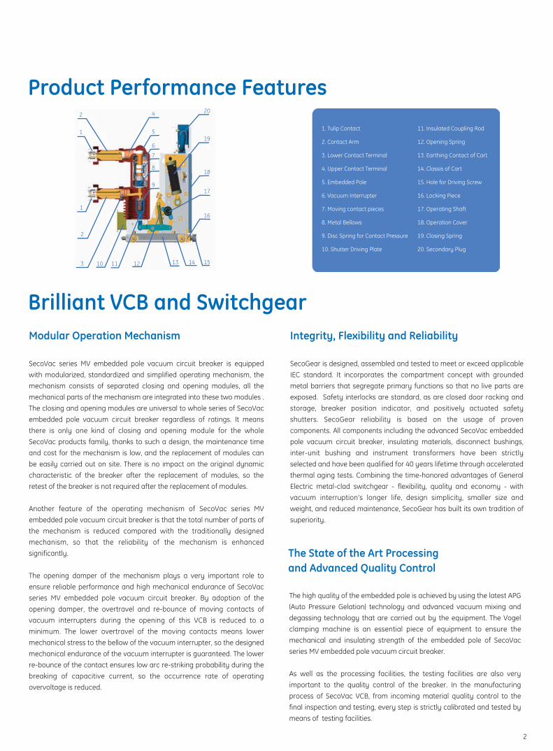
Product Performance Features
Brilliant VCB and Switchgear
1. Tulip Contact
2. Contact Arm
3. Lower Contact Terminal
4. Upper Contact Terminal
5. Embedded Pole
6. Vacuum Interrupter
7. Moving contact pieces
8. Metal Bellows
9. Disc Spring for Contact Pressure
10. Shutter Driving Plate
2
2
3
4
5
6
7
8
9
10 11 12 13 14 15
16
17
18
19
20
1
1
11. Insulated Coupling Rod
12. Opening Spring
13. Earthing Contact of Cart
14. Classis of Cart
15. Hole for Driving Screw
16. Locking Piece
17. Operating Shaft
18. Operation Cover
19. Closing Spring
20. Secondary Plug
2
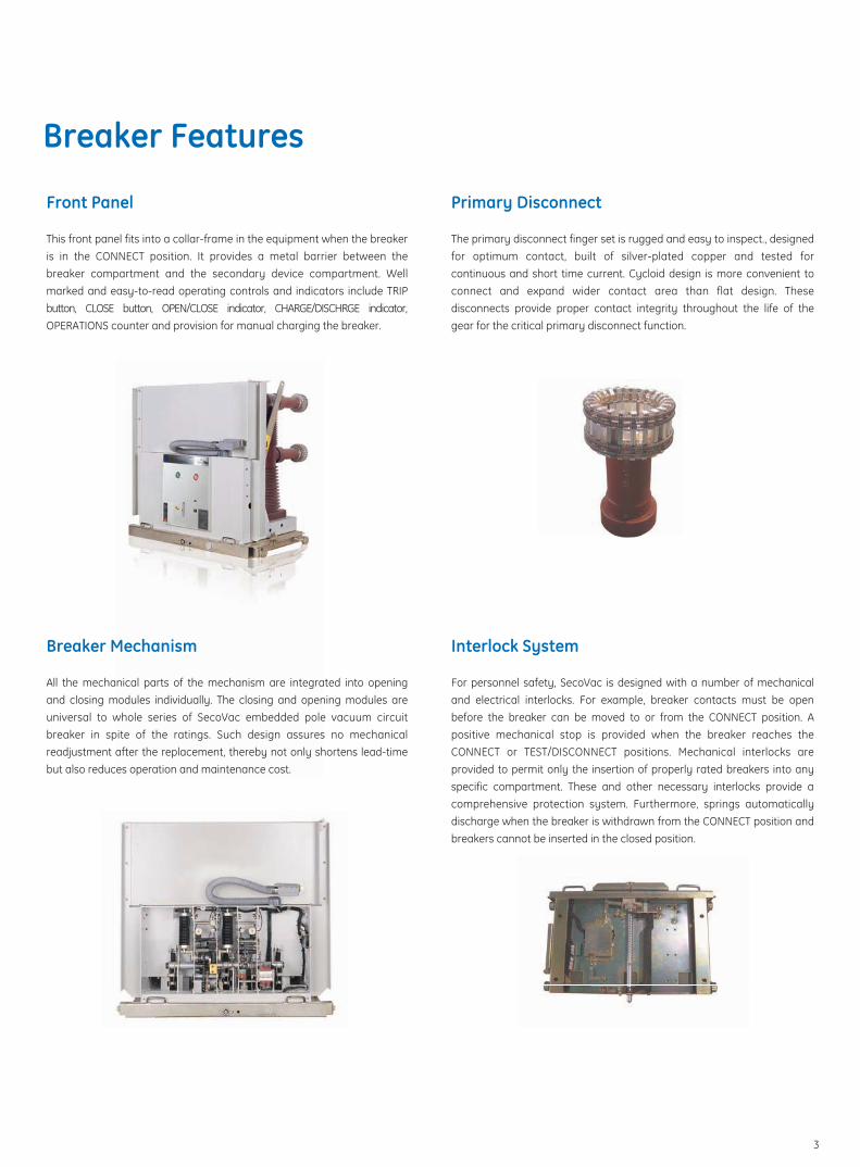
Front Panel
This front panel fits into a collar-frame in the equipment when the breaker is in the CONNECT position. It provides a metal barrier between the breaker compartment and the secondary device compartment. Well marked and easy-to-read operating controls and indicators include TRIP button, CLOSE button, OPEN/CLOSE indicator, CHARGE/DISCHRGE indicator, OPERATIONS counter and provision for manual charging the breaker.
Breaker Features
Primary Disconnect
The primary disconnect finger set is rugged and easy to inspect., designed for optimum contact, built of silver-plated copper and tested for continuous and short time current. Cycloid design is more convenient to connect and expand wider contact area than flat design. These disconnects provide proper contact integrity throughout the life of the gear for the critical primary disconnect function.
Breaker Mechanism
All the mechanical parts of the mechanism are integrated into opening and closing modules individually. The closing and opening modules are universal to whole series of SecoVac embedded pole vacuum circuit breaker in spite of the ratings. Such design assures no mechanical readjustment after the replacement, thereby not only shortens lead-time but also reduces operation and maintenance cost.
Interlock System
For personnel safety, SecoVac is designed with a number of mechanical and electrical interlocks. For example, breaker contacts must be open before the breaker can be moved to or from the CONNECT position. A positive mechanical stop is provided when the breaker reaches the CONNECT or TEST/DISCONNECT positions. Mechanical interlocks are provided to permit only the insertion of properly rated breakers into any specific compartment. These and other necessary interlocks provide a comprehensive protection system. Furthermore, springs automatically discharge when the breaker is withdrawn from the CONNECT position and breakers cannot be inserted in the closed position.
3
Panel Features
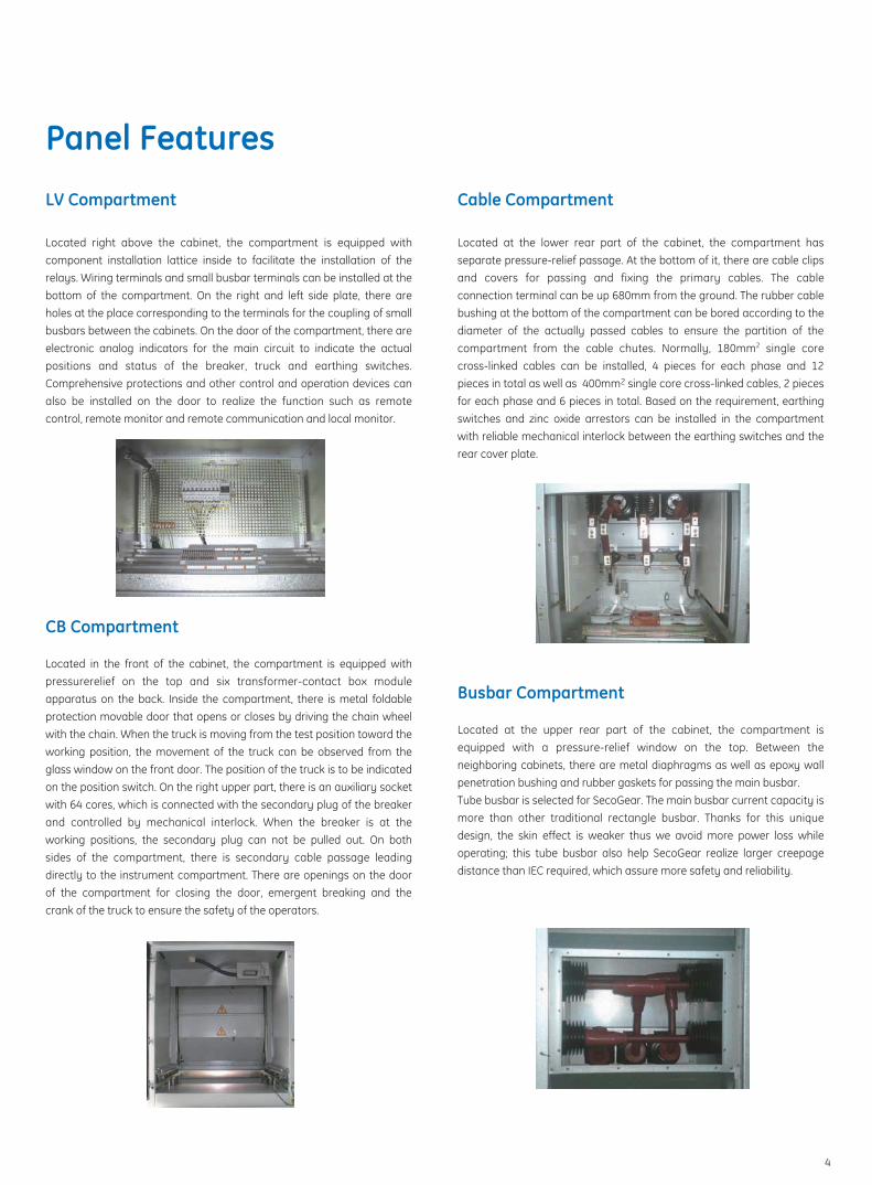
LV Compartment
Located right above the cabinet, the compartment is equipped with component installation lattice inside to facilitate the installation of the relays. Wiring terminals and small busbar terminals can be installed at the bottom of the compartment. On the right and left side plate, there are holes at the place corresponding to the terminals for the coupling of small busbars between the cabinets. On the door of the compartment, there are electronic analog indicators for the main circuit to indicate the actual positions and status of the breaker, truck and earthing switches. Comprehensive protections and other control and operation devices can also be installed on the door to realize the function such as remote control, remote monitor and remote communication and local monitor.
Cable Compartment
Located at the lower rear part of the cabinet, the compartment has separate pressure-relief passage. At the bottom of it, there are cable clips and covers for passing and fixing the primary cables. The cable connection terminal can be up 680mm from the ground. The rubber cable bushing at the bottom of the compartment can be bored according to the diameter of the actually passed cables to ensure the partition of the compartment from the cable chutes. Normally, 180mm2 single core cross-linked cables can be installed, 4 pieces for each phase and 12 pieces in total as well as 400mm2 single core cross-linked cables, 2 pieces for each phase and 6 pieces in total. Based on the requirement, earthing switches and zinc oxide arrestors can be installed in the compartment with reliable mechanical interlock between the earthing switches and the rear cover plate.
CB Compartment
Located in the front of the cabinet, the compartment is equipped with pressurerelief on the top and six transformer-contact box module apparatus on the back. Inside the compartment, there is metal foldable protection movable door that opens or closes by driving the chain wheel with the chain. When the truck is moving from the test position toward the working position, the movement of the truck can be observed from the glass window on the front door. The position of the truck is to be indicated on the position switch. On the right upper part, there is an auxiliary socket with 64 cores, which is connected with the secondary plug of the breaker and controlled by mechanical interlock. When the breaker is at the working positions, the secondary plug can not be pulled out. On both sides of the compartment, there is secondary cable passage leading directly to the instrument compartment. There are openings on the door of the compartment for closing the door, emergent breaking and the crank of the truck to ensure the safety of the operators.
Busbar Compartment
Located at the upper rear part of the cabinet, the compartment is equipped with a pressure-relief window on the top. Between the neighboring cabinets, there are metal diaphragms as well as epoxy wall penetration bushing and rubber gaskets for passing the main busbar. Tube busbar is selected for SecoGear. The main busbar current capacity is more than other traditional rectangle busbar. Thanks for this unique design, the skin effect is weaker thus we avoid more power loss while operating; this tube busbar also help SecoGear realize larger creepage distance than IEC required, which assure more safety and reliability.
4
Panel Features
Reliable Interlock System
For personnel safety, SecoGear is designed with a number of comprehensive electrical and mechanical interlocks, which is declared as but not limited to:a) When the earthing switch is under closing condition, the truck is unable to move from the off/test position toward the working position.b) Only when the truck is at the off/test position, can the earthing switch be closed.c) Only when the breaker is under opening condition, can the truck be moved in and out; when the truck is at the transition between the test and working positions inside the cabinet, the breaker is unable to be closed.d) When the truck is at the any position between the working position and the test position, the auxiliary circuit plug is unable to be pulled out. When the earthing switch is under opening condition, the cover plate on the back of the cabinet can’t be opened. If the cover plate is not completely in place, the earthing switch can’t be opened. When the cabinet door is closed, the truck can be moved in and out manually and the breaker as well the earthing switch can be opened and close.
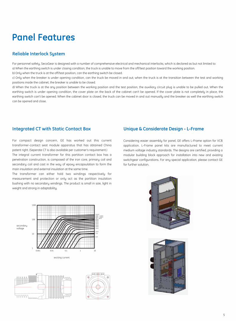
Integrated CT with Static Contact Box
For compact design concern, GE has worked out this current transformer-contact seat module apparatus that has obtained China patent right. (Seperate CT is also available per customer’s requirement.)The integral current transformer for this partition contact box has a penetration construction, is composed of the iron core, primary coil and secondary coil and cast in the way of epoxy encapsulation to form the main insulation and external insulation at the same time.The transformer can either hold two windings respectively for measurement and protection or only act as the partition insulation bushing with no secondary windings. The product is small in size, light in weight and strong in adaptability.
Considering easier assembly for panel, GE offers L-Frame option for VCB application. L-Frame panel kits are manufactured to meet current medium voltage industry standards. The designs are certified, providing a modular building block approach for installation into new and existing switchgear configurations. For any special application, please contact GE for further solution.
Unique & Considerate Design - L-Frame
secondaryvoltage
exciting current
10.001 0.01
10
100
1000
100/5
10.1 10
50/5
75/5
1000 1500/5
250/5
150/5200/5
750 800/5
500/5
300/5400/5
600/5
1200 1250/52000/5
5

Instrument Transformer
Current Transformer
The current transformer and voltage transformer are cast-resin type instrument transformers for measuring devices and protection devices of indoor application at the frequency of 50 or 60 Hz.The instrument transformers are molded in high quality epoxy resin to have a good performance at high polluted and humid area. The instrument transformer is designed to suite installation in tropical environment and it doesn’t need special maintenance.The instrument transformers can be mounted at any position. The light weight and small dimensions are the main features of its design.
The current transformer secondary terminals are located in recesses either in one or both sides of the transformer base, therefore giving two connection possibilities for installation flexibility.A ring type CT is also available for ground protection devices.
Voltage Transformer
The voltage transformers can be one or two poles type, with performances and accuracy classes suited to the functional requirements of the connected devices.When they are installed on a withdrawable truck they are fitted with primary fuses.The current and voltage transformers are designed to meet or exceed requirement of IEC60044-1 and IEC60044-2 standards respectively.
6
Technical Data
Description Unit Data
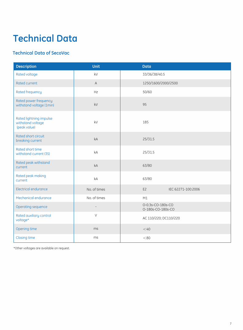
*Other voltages are available on request.
Rated voltage
Rated current
Rated frequency Rated power frequency withstand voltage (1min)
Rated lightning impulse withstand voltage (peak value)
Rated short circuit breaking current
Rated short time withstand current (3S)
Rated peak withstand current
Rated peak making current
Electrical endurance
Mechanical endurance
Operating sequence
Rated auxiliary control voltage* Opening time
Closing time
kV
A
Hz
kV
kV
kA
kA
kA
kA
No. of times
No. of times
-
V
ms
ms
33/36/38/40.5
1250/1600/2000/2500
50/60
95
185
25/31.5
25/31.5
63/80
63/80
E2 IEC 62271-100:2006
M1
O-0.3s-CO-180s-COO-180s-CO-180s-CO
AC 110/220; DC110/220
<40
<80
Technical Data of SecoVac
7
Unit
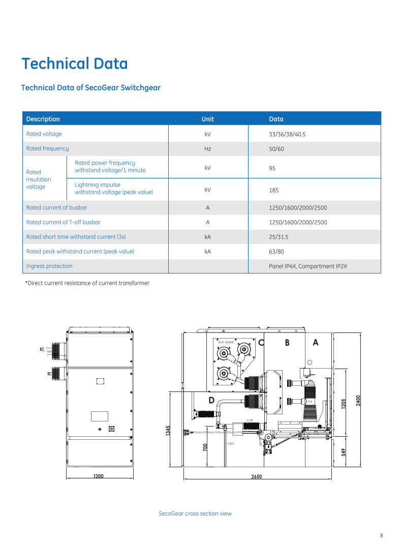
Technical Data of SecoGear Switchgear
Rated insulation voltage
Description Rated voltage
Rated frequency
Rated current of busbar
Rated current of T-off busbar
Rated short time withstand current (3s)
Rated peak withstand current (peak value)
Ingress protection
Rated power frequencywithstand voltage/1 minute
Lightning impulsewithstand voltage (peak value)
kV
Hz
Data
kV
kV
A
A
kA
kA
33/36/38/40.5
50/60
95
185
1250/1600/2000/2500
1250/1600/2000/2500
25/31.5
63/80
Panel IP4X, Compartment IP2X
SecoGear cross section view
*Direct current resistance of current transformer
MAIN BUSBAR
E-SW
VCB
CABIE
700
2650
549
1205
2400
1345
ABC
D
1200
Technical Data
8

Normal Service Conditions:
Ambient temperature: the temperature of the ambient air shall not be higher than +40oC and not lower than -15oC and the mean value measured within 24h shall not exceed +35oC.
Ambient humidity: The average of relative humidity measured in 24h shall not be more than 95% and the monthly average not more than 90%.
Height above the sea level shall not be more than 1000m.
Seismic intensity is not more than 8 degree.
The asperity under the operation condition free of flammable gas and fire, danger of explosion, condensation and dirt: in accordance with the specification in level 1 in IEC62271-200: 2003.
Note: when the relative humidity is above 70%, the heater shall be switched on to prevent condensation. When the normal service condition is different from the above mentioned, please consult the manufacturer.
9
�
�
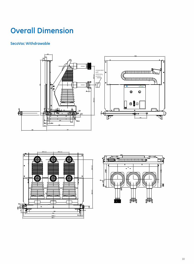
Overall DimensionSecoVac Withdrawable
�
10
cooperatedwithstationarycontact
839
547
Ø65160
460
537517
360 75
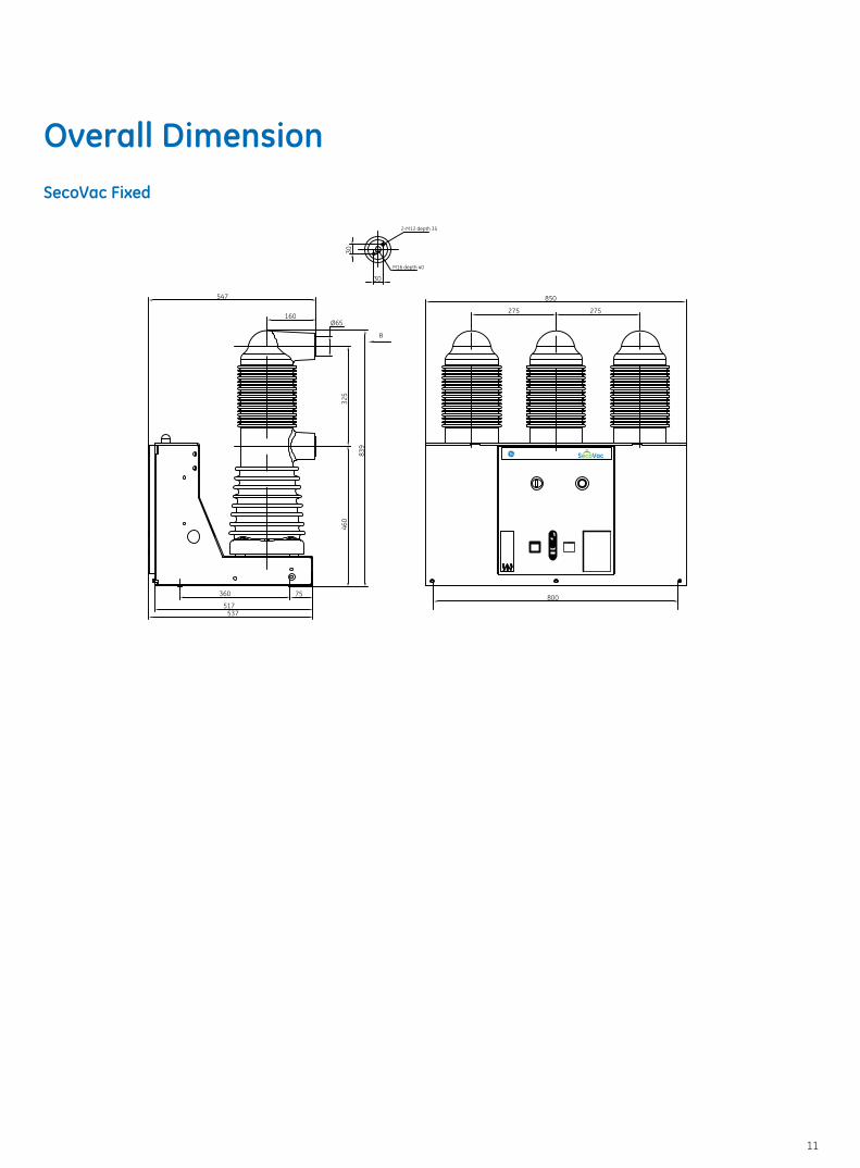
325
850
800
275275
M16 depth 40
30
30
2-M12 depth 35
B
SecoVac Fixed
Overall Dimension
11
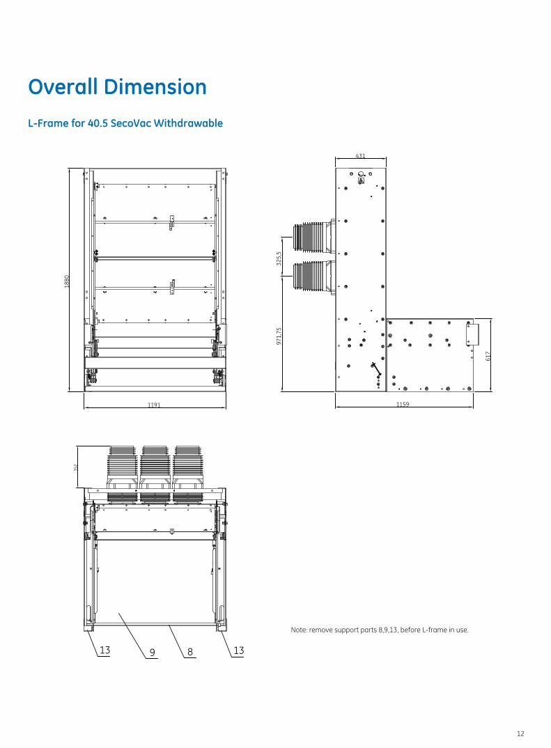
1159
971,
7532
5,5
431
617
1191
1880
1389
352
13
L-Frame for 40.5 SecoVac Withdrawable
Note: remove support parts 8,9,13, before L-frame in use.
Overall Dimension
12
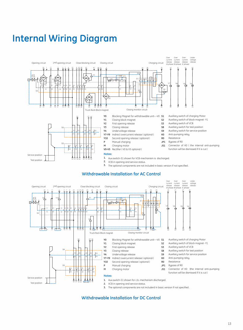
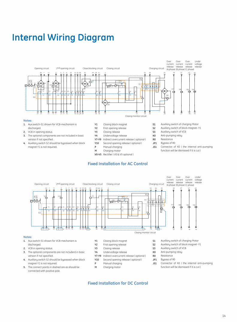
Internal Wiring Diagram
Closing circuitClose blocking circuit2nd opening circuitOpening circuit Charging circuit
Overcurrentrelease(A phase)
Overcurrentrelease(B phase)
Overcurrentrelease(C phase)
Undervoltagerelease
Closing monitor circuitTruck Rack Block magnet
Blocking Magnet for withdrawable unit---V0Closing block magnet First opening releaseClosing releaseUndervoltage releaseIndirect overcurrent release ( optional )Second opening release ( optional )Manual chargingCharging motorRectifier ( V0 & V5 optional )
Auxiliary switch of charging MotorAuxiliary switch of block magnet- Y1Auxiliary switch of VCBAuxiliary switch for test positionAuxiliary switch for service positionAnti-pumping relayResistanceBypass of R0Connector of K0 ( the internal anti-pumping function will be dismissed if it is cut )
Y0Y1Y2Y3Y4Y7-Y9Y10PMV0-V5
1.2.3.
S1S2S3S8S9K0R0JP1JS1
Aux.switch-S1 shown for VCB-mechanism is discharged.VCB in opening and service status.The optional components are not included in basic version if not specified .
Notes:
Closing circuitClose blocking circuit2nd opening circuitOpening circuit Charging circuit
Overcurrentrelease(A phase)
Overcurrentrelease(B phase)
Overcurrentrelease(C phase)
Undervoltagerelease
Closing monitor circuitTruck Rack Block magnet
Blocking Magnet for withdrawable unit---V0Closing block magnet First opening releaseClosing releaseUndervoltage releaseIndirect overcurrent release ( optional )Second opening release ( optional )Manual chargingCharging motor
Auxiliary switch of charging MotorAuxiliary switch of block magnet- Y1Auxiliary switch of VCBAuxiliary switch for test positionAuxiliary switch for service positionAnti-pumping relayResistanceBypass of R0Connector of K0 (the internal anti-pumping function will be dismissed if it is cut )
Y0Y1Y2Y3Y4Y7-Y9Y10PM
1.2.3.
S1S2S3S8S9K0R0JP1JS1
Aux.switch-S1 shown for c.b.-mechanism discharged.VCB in opening and service status.The optional components are not includerd in basic version if not specified .
Notes:
Withdrawable Installation for AC Control
Withdrawable Installation for DC Control
Service position
Test position
Service position
Test position
13
Closing circuitClose blocking circuit2nd opening circuitOpening circuit Charging circuit
Overcurrentrelease(A phase)
Overcurrentrelease(B phase)
Overcurrentrelease(C phase)
Undervoltagerelease
Closing circuitClose blocking circuit2nd opening circuitOpening circuit Charging circuit
Overcurrentrelease(A phase)
Overcurrentrelease(B phase)
Overcurrentrelease(C phase)
Undervoltagerelease
Closing monitor circuit
Aux.switch-S1 shown for VCB-mechanism is discharged.VCB in opening status.The optional components are not includerd in basic version if not specified .Auxiliary switch S2 should be bypassed when block magnet Y1 is not required.The connect points in dashed are as should be connected with positive pole.
Closing block magnet First opening release Closing releaseUndervoltage release Indirect overcurrent release ( optional )Second opening release ( optional )Manual chargingCharging motor
Auxiliary switch of charging MotorAuxiliary switch of block magnet- Y1Auxiliary switch of VCBAnti-pumping relayResistanceBypass of R0Connector of K0 ( the internal anti-pumping function will be dismissed if it is cut )
Y1Y2Y3Y4Y7-Y9Y10PM
S1S2S3K0R0JP1JS1
1.
2.3.
4.
5.
Notes:
Closing monitor circuit
Aux.switch-S1 shown for VCB-mechanism is discharged.VCB in opening status.The optional components are not included in basic version if not specified .Auxiliary switch S2 should be bypassed when block magnet Y1 is not required.
Closing block magnet First opening release Closing releaseUndervoltage release Indirect overcurrent release ( optional )Second opening release ( optional )Manual chargingCharging motorRectifier ( V0 & V5 optional )
Auxiliary switch of charging MotorAuxiliary switch of block magnet- Y1Auxiliary switch of VCBAnti-pumping relayResistanceBypass of R0Connector of K0 ( the internal anti-pumping function will be dismissed if it is cut )
Y1Y2Y3Y4Y7-Y9Y10PMV0-V5
S1S2S3K0R0JP1JS1
1.
2.3.
4.
Notes:
Fixed Installation for DC Control
Fixed Installation for AC Control
Internal Wiring Diagram
14
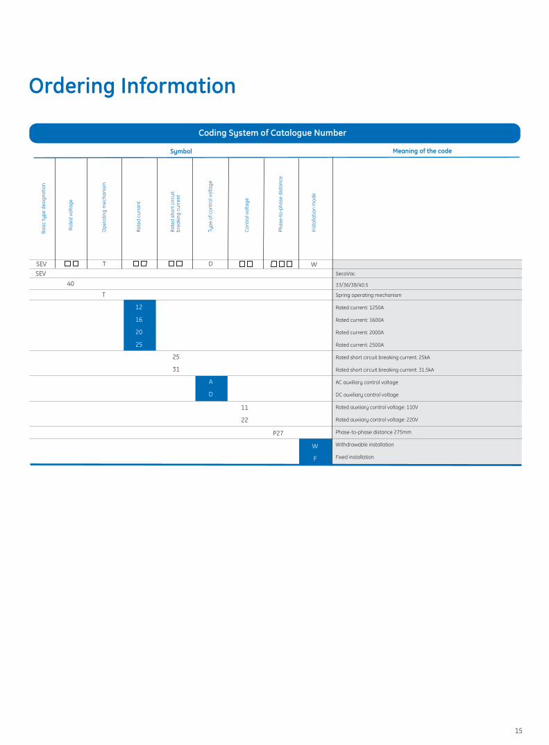
Ordering Information
Coding System of Catalogue Number
Symbol Meaning of the code
Basi
c ty
pe d
esig
natio
n
Rate
d vo
ltage
Ope
ratin
g m
echa
nism
Rate
d cu
rren
t
Rate
d sh
ort c
ircui
t br
eaki
ng c
urre
nt
Type
of c
ontr
ol v
olta
ge
Cont
rol v
olta
ge
Phas
e-to
-pha
se d
ista
nce
SEV T DSEV
40
11
22
Inst
alla
tion
mod
e
W
W
F
P27
T
A
D
12
16
20
25
25
31
SecoVac
33/36/38/40.5
Spring operating mechanism
Rated current: 1250A
Rated current: 1600A
Rated current: 2000A
Rated current: 2500A
Rated short circuit breaking current: 25kA
Rated short circuit breaking current: 31.5kA
AC auxiliary control voltage
DC auxiliary control voltage
Rated auxiiary control voltage: 110V
Rated auxiiary control voltage: 220V
Phase-to-phase distance 275mm
Withdrawable installation
Fixed installation
15
Breaker type
Rated voltage
Rated current
Rated short-circuit
breaking current
Distance of pole (P)
Motor-operated (M)
*Blocking electromagnet
Y1
Closing/ Opening
Module Y2、Y3
Over-current releases
Y7、Y8、Y9(optional)
Under-voltage release
Y4(optional)
Truck blocking
Y0(optional)
Auxiliary contactors
Anti-pump relay K0
(optional)
Secondary wiring
Withdrawable
(W type)
L-Frame (optional)
Fixed
(F type)
Other items
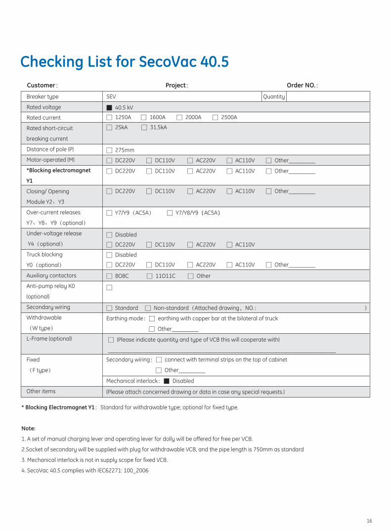
Customer: Project: Order NO.:
SEV Quantity
40.5 kV
1250A 1600A 2000A 2500A
25kA 31.5kA
Y7/Y9(AC5A) Y7/Y8/Y9 AC5A
Disabled
275mm
DC220V DC110V AC220V AC110V Other_________
DC220V DC110V AC220V AC110V Other_________
DC220V DC110V AC220V AC110V Other_________
DC220V DC110V AC220V AC110V
Disabled
DC220V DC110V AC220V AC110V Other_________
8O8C 11O11C Other
Standard Non-standard(Attached drawing,NO.: )
Earthing mode: earthing with copper bar at the bilateral of truck
Other_________
Secondary wiring: connect with terminal strips on the top of cabinet
Other_________
(Please indicate quantity and type of VCB this will cooperate with)
_____________________________________________________________________________
Mechanical interlock: Disabled
(Please attach concerned drawing or data in case any special requests.)
* Blocking Electromagnet Y1:Standard for withdrawable type; optional for fixed type.
Note:
1. A set of manual charging lever and operating lever for dolly will be offered for free per VCB.
2.Socket of secondary will be supplied with plug for withdrawable VCB, and the pipe length is 750mm as standard
3. Mechanical interlock is not in supply scope for fixed VCB.
4. SecoVac 40.5 complies with IEC62271: 100_2006
Checking List for SecoVac 40.5
16
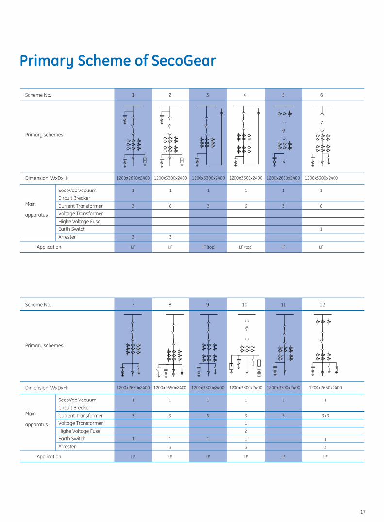
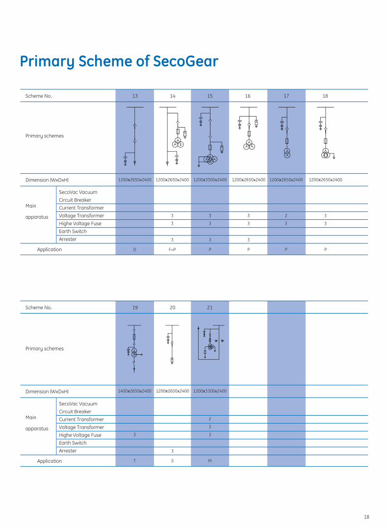
Primary Scheme of SecoGear
Scheme No.
Dimension (WxDxH)
Application
Primary schemes
Primary schemes
Main
apparatus
SecoVac VacuumCircuit BreakerCurrent TransformerVoltage TransformerHighe Voltage FuseEarth SwitchArrester
1 2 3 4 5 6
Scheme No.
Dimension (WxDxH)
Application
Main
apparatus
SecoVac VacuumCircuit BreakerCurrent TransformerVoltage TransformerHighe Voltage FuseEarth SwitchArrester
7 8 9 10 11 12
1200 2650 2400
1
3
3
I.F
1200 3300х2400
1
6
3
I.F
1200 3300х2400
1
3
I.F (top)
1200 3300х2400
1
6
I.F (top)
1200 2650х2400
1
3
I.F
1200 3300х2400
1
6
1
I.F
1200 2650х2400
1
3
1
I.F
1200 2650х2400
1
3
1
3
I.F
1200 3300х2400
1
6
1
I.F
1200 3300х2400
1
3
1
2
1
3
I.F
1200 3300х2400
1
5
I.F
1200 2650х2400
1
3+3
1
3
I.F
17
Scheme No.
Dimension (WxDxH)
Application
Main
apparatus
SecoVac VacuumCircuit BreakerCurrent TransformerVoltage TransformerHighe Voltage FuseEarth SwitchArrester
13 14 15 16 17 18
Dimension (WxDxH)
Application
Main
apparatus
SecoVac VacuumCircuit BreakerCurrent TransformerVoltage TransformerHighe Voltage FuseEarth SwitchArrester
19 20 21Scheme No.
V
1200 2650х2400
D
1200 2650х2400
3
3
3
F+P
1400 2650х2400
3
T
1200 2650х2400
3
S
1200 3300х2400
2
3
3
M
1200 3300х2400
3
3
3
P
1200 2650х2400
3
3
3
P
1200 2650х2400
2
3
P
1200 2650х2400
3
3
P
Primary schemes
Primary schemes
Primary Scheme of SecoGear
18
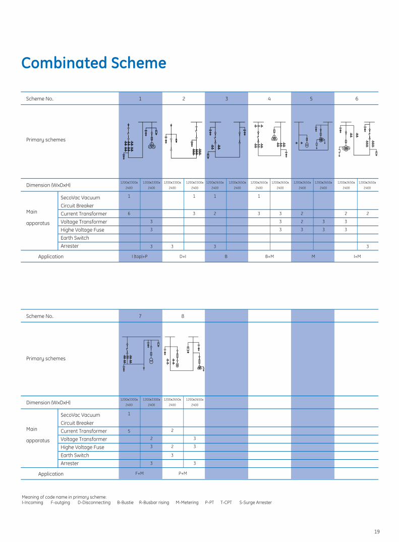
Combinated Scheme
Scheme No.
Dimension (WxDxH)
Application
Main
apparatus
SecoVac VacuumCircuit BreakerCurrent TransformerVoltage TransformerHighe Voltage FuseEarth SwitchArrester
1 2 3 4 5 6
V
V
Scheme No.
Dimension (WxDxH)
Application
Main
apparatus
SecoVac VacuumCircuit BreakerCurrent TransformerVoltage TransformerHighe Voltage FuseEarth SwitchArrester
7 8
3
3
3
3
3
3
2
2
3
1
6
1
2
3
1
3
1200 3300х
2400
1200 3300х
2400
I (top)+P
3
1200 3300х
2400
1200 3300х
2400
D+I
1
3
1200 2650х
2400
1200 2650х
2400
B+M
2
3
3
1
5
1200 3300х
2400
1200 3300х
2400
F+M
3
3
3
2
2
3
1200 2650х
2400
1200 2650х
2400
P+M
3
3
1200 2650х
2400
1200 2650х
2400
M
2
3
3
2
3
1200 2650х
2400
1200 2650х
2400
I+M
1200 2650х
2400
1200 2650х
2400
B
Meaning of code name in primary scheme: I-Incoming F-outging D-Disconnecting B-Bustie R-Busbar rising M-Metering P-PT T-CPT S-Surge Arrester
V
Primary schemes
Primary schemes
19
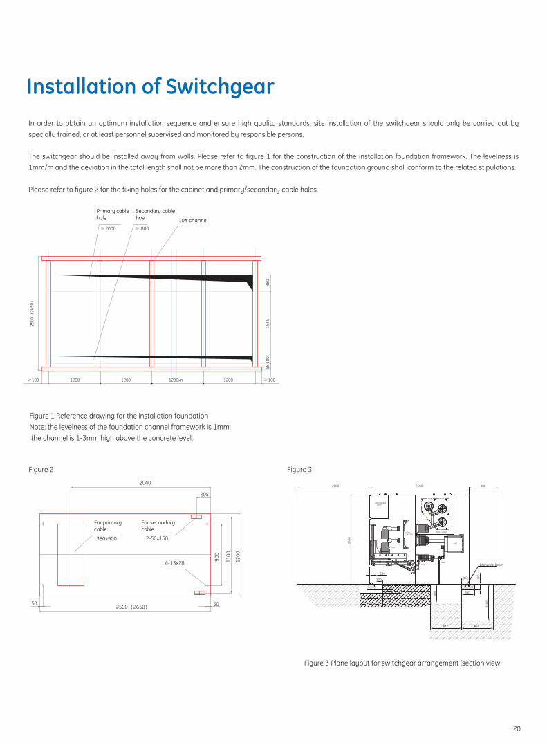
Installation of SwitchgearIn order to obtain an optimum installation sequence and ensure high quality standards, site installation of the switchgear should only be carried out by specially trained, or at least personnel supervised and monitored by responsible persons.
The switchgear should be installed away from walls. Please refer to figure 1 for the construction of the installation foundation framework. The levelness is 1mm/m and the deviation in the total length shall not be more than 2mm. The construction of the foundation ground shall conform to the related stipulations.
Please refer to figure 2 for the fixing holes for the cabinet and primary/secondary cable holes.
10# channel
Primary cablehole
Secondary cablehoe
Figure 1 Reference drawing for the installation foundationNote: the levelness of the foundation channel framework is 1mm; the channel is 1-3mm high above the concrete level.
Figure 2 Figure 3
2500(
2650)
≥1001200 1200 1200xn 1200≥100
6518
015
5538
0
≥2000 ≥ 800
380x900 2-50x150
4-13x28
2500 2650 5050
2040
205
900
1100
1200
Figure 3 Plane layout for switchgear arrangement (section view)
COMPTLOW VOLTAGE
MAIN BUSBAR
WCT
E-SW
VCB
METALSHUTTER
2000 2650 800
2400
630
230
200
130
100
250
350
150
500
1000
837 850
200
CABIE10#channel beam
For primarycable
For secondarycable
20

GE imagination at work
This company reserves the right to improvethe products according to the situation.
This publication describes the status of the products at the time of its issuing and may not reflect future condition of the product.
Publication NO.GE/SG40.5/CA/2009/001
GEIndustrial


