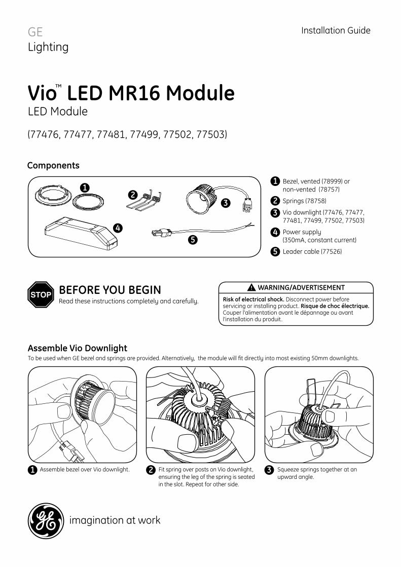
Assemble Vio Downlight imagination at work Vio TM LED MR16 Module LED Module (77476, 77477, 77481, 77499, 77502, 77503) GE Lighting Installation Guide 1 1 2 2 3 3 4 4 5 5 Bezel, vented (78999) or non-vented (78757) Springs (78758) Vio downlight (77476, 77477, 77481, 77499, 77502, 77503) Power supply (350mA, constant current) Leader cable (77526) Components Assemble bezel over Vio downlight. Fit spring over posts on Vio downlight, ensuring the leg of the spring is seated in the slot. Repeat for other side. 1 2 BEFORE YOU BEGIN Read these instructions completely and carefully. WARNING/ADVERTISEMENT Risk of electrical shock. Disconnect power before servicing or installing product. Risque de choc électrique. Couper l’alimentation avant le dépannage ou avant l’installation du produit. Squeeze springs together at an upward angle. 3 To be used when GE bezel and springs are provided. Alternatively, the module will fit directly into most existing 50mm downlights.
Assemble bezel over Vio downlight. Fit spring over posts on Vio downlight, ensuring the leg of the spring is seated in the slot. Repeat for other side.
1 2
BEFORE YOU BEGINRead these instructions completely and carefully.
WARNING/ADVERTISEMENT
Risk of electrical shock. Disconnect power before servicing or installing product. Risque de choc électrique. Couper l’alimentation avant le dépannage ou avant l’installation du produit.
Squeeze springs together at an upward angle.
3
To be used when GE bezel and springs are provided. Alternatively, the module will fit directly into most existing 50mm downlights.
Electrical Connections
SIGN083-R032510
RISK OF ELECTRIC SHOCK:• Turn power OFF before inspection, installation or removal.
RISK OF FIRE:• Follow all NEC and local codes.• Use only approved wire for input/output connections. Minimum size 18 AWG (0.82 mm2)
WARNING!
Conforms to the following standards:
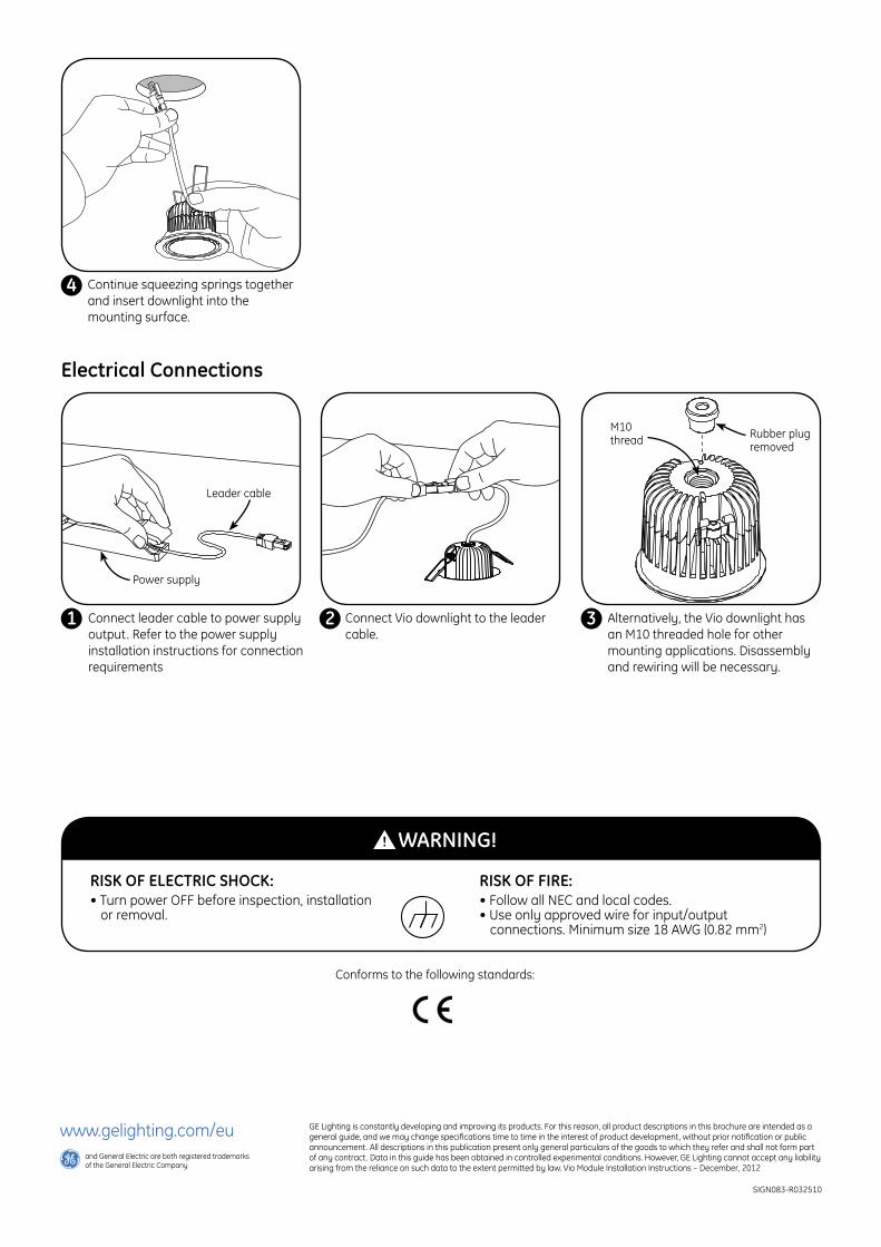
Continue squeezing springs together and insert downlight into the mounting surface.
Alternatively, the Vio downlight has an M10 threaded hole for other mounting applications. Disassembly and rewiring will be necessary.
4
3
M10 thread Rubber plug
removed
Power supply
Leader cable
Connect leader cable to power supply output. Refer to the power supply installation instructions for connection requirements
Connect Vio downlight to the leader cable.
1 2
GE Lighting is constantly developing and improving its products. For this reason, all product descriptions in this brochure are intended as a general guide, and we may change specifications time to time in the interest of product development, without prior notification or public announcement. All descriptions in this publication present only general particulars of the goods to which they refer and shall not form part of any contract. Data in this guide has been obtained in controlled experimental conditions. However, GE Lighting cannot accept any liability arising from the reliance on such data to the extent permitted by law. Vio Module Installation Instructions – December, 2012
www.gelighting.com/euand General Electric are both registered trademarks of the General Electric Company