39
1775 N. Lapeer Rd. Unit B Oxford, MI 48371 248-393-1621 Gen. II Ford 300 Install Property of American Airlines

1775 N. Lapeer Rd. Unit B
Oxford, MI 48371
248-393-1621
Gen. II Ford 300Install
Prope
rty o
f Am
erica
n Airli
nes

2
TABLE OF CONTENTS
1. Kit Contents……………………………………………………….…..….3
2. Installation Instructions…………………………….………….……4
3. Component Description……………………………..…….………..10
4. Final Checks……………………………………………………..………..12
5. Installation tips (helpful installation pictures)…………..13
6. Component Parts and Part Numbers………………………….19
7. Troubleshooting……………………………………………..………....20
8. Diagnostic Trouble Codes………………………………..………… 35
9. ECM Pin Out and Wire Coding…………………………………….38
10. Wiring Diagram……………………………………………………39
Prope
rty o
f Am
erica
n Airli
nes

3
Congratulations on the purchase of your Affordable Fuel Injection™ TBIsystem. We are confident that this purchase will give you the performanceand driveability you deserve from your GSE equipment. The followinginstructions are intended to provide you with thorough description forinstalling your TBI system. If you do not understand any part of theinstructions, need clarification or simply need more information, please e-mail us at: [email protected]. Please read throughthe instructions completely before beginning your installation. Many of yourquestions may be covered within this manual.
Verify that all of the components are included in your shipment.
1. Wiring Harness2. ECM3. Throttle Body (with IAC and TPS)4. ECT sensor (Engine Coolant Temp)5. IAT sensor (Installed in throttle body)6. MAP Sensor (Manifold Absolute Pressure)7. Heated O2 Sensor with exhaust ring for
installation8. Fuel Pump Relay9. Power Relay10.Check Engine Light11.Hall Effect distributor12.Distributor module13. Fuse protection link14. Fuel filter15. Inline Fuel Pump16.Fuel Pressure regulator17.Pre made fuel lines (optional)18.ECM bracket and mounting hardware19.ECM controlled start relay (optional)20. Low fuel shut off sensor (optional)21. Low fuel indicator light (optional)22.Electric Fan Relay (optional)
Prope
rty o
f Am
erica
n Airli
nes

4
INSTALLATION INSTRUCTIONS
NOTE: THIS IS A CUSTOM FUEL INJECTION SYSTEM BUILT FORYOUR GSE EQUIPMENT. AS WITH ALL CUSTOM PROJECTS SOMEFABRICATION MAY BE REQUIRED. YOU MAY ALSO REQUIRESOME SMALL PARTS THAT ARE NOT INCLUDED IN THE KIT.
ECMThe ECM is the central unit of the fuel injection system. This unit providesthe signals that trigger the injectors. The ECM is mounted in the samelocation as the mechanical fuel pump was located. An extra thick gasket issupplied to insure a secure seal at this location.
This is a state of the art ECM which is weatherproof, shockproof and heatproof.
WIRING HARNESSThe wiring harness included with this kit has been specially built for yourunique application. This harness only includes the connectors and leads thatare required to run your particular engine based upon the orderspecifications. Therefore, if there are leftover parts this indicates thatan error has been made during assembly and installation of thesystem. Each connector will be marked with a label to the correct sensorthat it is to be connected too. In the following section we will describeeach sensor and the connector that attaches to it. The wiring harness isfabricated to allow the proper sensor to be hooked up to the respectiveconnector. The “keying” of the connector will not allow for an improperconnection.
There is one fusible link required which is to be securely connected to the redbattery wire after this wire is cut to length. Fuses which also protect thesystem are located integral to the relays in some applications.
The PINK power wire needs to be attached to an Ignition 1 (IGN1,battery power only with key on or in the crank position) powersource. Ensure that this is an ignition 1 source. An ignition 1 sourceis 12volts available any time that the key is not in the off position.Also this PINK wire must have 12V while the vehicle is in thecranking mode (starting). This means the wire will have power whenthe key is on, or start, or back to on. Usually this wire can be takenfrom the proper terminal on the ignition switch, the power side of
Prope
rty o
f Am
erica
n Airli
nes

5
the coil (+), or from the fuse box. The system will not work if poweris not provided to the (PINK) ignition wire while cranking.
The red wire is to be connected to a direct battery lead which has12v always feeding it; a direct connection to the battery or starterrelay is optimal. It is important that these wires are connected to theindicated source or your fuel injection system will not operateproperly.
A main fuse link is provided which is the main fuse protection for theentire system. This link is to be installed at the battery source andsecured and sealed to the red battery wire. Two additional fuses areused for protection and located in the relays.
It is very important that the ECM and components be suppliedwith proper voltage at all times. Improper operation of thecharging system can result in system malfunctions anddrivability issues.
Included are two relays, a power relay and fuel pump relay. These relays areof the same design and can be used for either application. The power relayis used to ensure proper voltage is supplied to your system so as not to taxthe current wiring of the vehicle with undue voltage requirements. Thepower relay connects to Ign. 1 feed to power up the relay (pink wire youconnected above), and the input to the relay is battery powered. Thisbattery lead is labeled and can be attached directly to the battery, the startersolenoid, or any other appropriate full time 12-volt supply. We have includeda length of wire long enough to choose your own connection option. Insurethat the main fuse circuit protection is installed between the battery powersource and the red battery wire. A low temperature solder connector is alsoprovided to provide a secure and sealed connection. The fuel pump relay iscontrolled by the ECM and no connections are required except for the powerwire to the fuel pump itself.
An ALDL connector is another extension of the harness which is located inyour wiring harness at the back side of the engine.. This connector is a 4 pinweatherpak connector with a sealed connector installed to protect it from theelements. This connector allows the use of a C.A.N. based OBDII scan toolto read operational data of the unit as well as read and clear diagnosticcodes. An OBDII connector with the proper Weatherpak termination is usedwith this to gain access to the data stream of the ECM.
Two wires are also provided which connect to a check engine light. Thislight can be mounted in the dash, use an empty “idiot light” socket in theinstrument panel, or mounted in a small bracket under the dash. It shouldbe mounted in an area noticeable in case of any malfunctions. De-icerapplications typically choose to mount the ALDL connector and the checkengine light inside the control box. This allows for diagnostics and
Prope
rty o
f Am
erica
n Airli
nes

6
troubleshooting for the technicians only. The wire from the ECM is theground for the light. When a fault exists, or the system is in diagnosticmode, or the engine is not running with the key on, the light is illuminated.The other side of the light requires a 12v ignition feed that has been suppliedand marked for this purpose.
Several black wires with an eyelet on the end are to be bolted to anappropriate engine ground. Insure that you have cleaned the surface wherethis wire will mate to. Empty threaded holes in the intake manifold orcylinder head have been good locations for this wire. Two star washers havebeen provided to insure a good continuity to ground.
It is advisable to run a separate ground wire from the battery to the frame ofthe vehicle. It is also advisable to run another ground wire from the locationof the ground wire from the harness to the frame at the same mountinglocation as the wire from the battery.
FUEL PUMPAn external inline fuel pump has been included with your TBI system. Thispump delivers a variable fuel pressure to the throttle body through the fuelpressure regulator. This regulator regulates the fuel pressure between 42 –55 psi and returned to the fuel tank. This pump should be mounted to theframe of your GSE equipment. If necessary weatherproof the pump bymounting a cover over it.. A fuel filter is to be installed in the fuel linePRIOR to the fuel pump. Premature failure of the pump can be the result ofimproper fuel filter installation. Some aftermarket high density fuel filterscan cause a large drop in fuel pressure under load and are not recommendedfor use with your system. If you are using high density filters insure that youhave proper fuel pressure during all modes of operation.
If your equipment is fitted with an electric pusher or scavenger pump thesepumps may not provide enough fuel flow for the system to operate properly.To insure that proper pressure is being maintained, monitor fuelpressure over time if you are using one of these pumps. In previouscases these pumps have been removed.
A 12 or 16 Ga. pink wire labeled “Fuel Pump”, with sufficient length hasbeen included with the wiring harness for the pump power feed. This wirecomes from the fuel pump relay which can be mounted in a convenient underhood location. It may be desirable to enclose these relays in a plastic box orprovide suitable protection from any elements. The mounting and theground are very important for proper operation of the fuel pump. Aground wire is to be attached to a stable clean body ground or runback to a battery ground. An improper ground will result in insufficientfuel flow and/or premature pump failure. Mount the fuel pump in the bracketsupplied or similar, to keep the pump noise from radiating into the vehicle.
Prope
rty o
f Am
erica
n Airli
nes
7
You may want to “prime” the fuel feed line with gasoline to aid in the primingof the pump for proper operation.
FUEL LINES & PRESSURE REGULATORNOTE: Only use fuel line rated for fuel injection. If your kit wasordered with premade fuel line this line is already fuel injectionrated. Steel line or braided fuel line is the most desirable for thisapplication.
Your TBI fuel injection system only requires one fuel line to the throttle bodyfrom the fuel pressure regulator for proper operation. This fuel line begins atthe fuel pump, is “T’d” into the side of the fuel pressure regulator andattached to the throttle body. (See Picture next section) An additional fuelline attaches to the bottom of the fuel pressure regulator and is used toreturn the low pressure regulated fuel back to the fuel tank. The idealinstallation incorporates both the fuel feed and return lines attached to thefuel tank. Some fuel tanks are supplied with a tank vent for evaporativeemission purposes. These fittings usually have a restriction incorporatedinternally and are not sufficient for a fuel return. If the restriction can beremoved and the fitting is of sufficient size, this can be used for a return. Donot eliminate this fitting for evaporative emissions purposes if these itemsare still in use. Insure that any factory fittings that are on the fuel tank arefree flowing and do not restrict the flow of fuel back to the fuel tank.
On TUG brand units most fuel tanks have two fittings on the bottom of thetank that can be used. The one fitting that is currently used can be used forthe feed line to the fuel pump. The other plugged line can be used as areturn line. This second fitting has a tube internally in the fuel tank thatallows for a return of the fuel higher in the tank; insure that you do not usethis for the feed line. Some stations have chosen to install a shut off valve inthe feed line prior to the fuel filter for easier fuel filter service purposes.
THROTTLE BODYYour AFI throttle body is a direct replacement for your 1 bbl. carburetor. Theair cleaner stud mounting bar on your current carburetor is to be removedand installed onto your new throttle body. The throttle lever is positionedsimilar to your throttle lever on your carburetor. The throttle cable willattach to your new throttle body in the same manner as your carburetor. Ifyour current carburetor has an additional throttle return spring it is advisableto maintain this same return spring.
Ensure that smooth unrestricted movement can be obtained from theaccelerator pedal from idle to WOT (Wide Open Throttle). Connect the wiresto the injector, TPS (Throttle Position Sensor), IAT (Intake Air Temperature)and IAC (Idle Air Control) valve.
Prope
rty o
f Am
erica
n Airli
nes

8
Connect the fuel line to the side of the throttle body and direct to the backside of the engine. This is an AN type or barbed pipe thread fitting and issufficient for the pressures encountered with the fuel injection system.
ENGINE SENSORS
MAP SENSORThe MAP sensor is a very important part of the fuel injection system. Thissensor sends a voltage to the ECM in relation to the amount of vacuum(pressure) the engine is creating. This signal is used in conjunction with theengine speed to infer the amount of air that is being used by the engine.This is what is called a speed/density system. Because fuel control is verydependent upon this signal it is very important to install correctly. Thissensor is to be installed as close to the manifold vacuum source as possible.The port on the sensor is to face down with the vacuum line attached. Thisvacuum line should have no sags or dips and the length should be asshort as possible. Some people install this sensor in the center of thefirewall towards the cowl or even under the air cleaner at times. Attentionneeds to be given to the connection of the vacuum line ensuring no leaks.For the velocity governor application insure that the vacuum line is connectedto the manifold below the governor.
COOLANT SENSORThe coolant sensor is just like it sounds; it sends an electrical signal to theECM in proportion to the engine coolant temperature. This sensor is to beinstalled before the thermostat preferably or in the block itself. (See picturenext section) There is a plug in the rear of the block that can be used for theECT sensor or anywhere on the engine side of the thermostat. Connect thetwo-wire connector when installed. Ensure that there are no coolant leaksfrom the threads of the sensor. It is also important that a continuous flow ofcoolant is present at the tip of the sensor or a false reading and enginedamage can occur.
INTAKE AIR TEMPERATURE SENSORThe IAT is just like it sounds; it sends an electrical signal to the ECM inproportion to the air temperature in the throttle body. This sensor is alreadymounted in the side of the throttle body. Connect the two-wire connectorwhen installed. Ensure that there are no leaks from the threads of thesensor if replacing the sensor.
HEATED OXYGEN SENSORThe oxygen sensor is installed in the exhaust pipe and samples the exhaustto determine if the engine is running rich or lean of 14.7:1 air/fuel ratio. TheO2 sensor should be installed as close to the engine as possible. Manyreplacement manifolds have a boss already tapped that will accept an O2sensor. It is preferable to use this location or drill and tap that location onthe manifold. A threaded boss has been included with your kit that can bewelded into the exhaust pipe to hold the O2 sensor. (See Picture next
Prope
rty o
f Am
erica
n Airli
nes

9
section) Placement of this boss should always be in a position that issomewhere between horizontal to vertical. In no instance should the sensorwire be pointed in a position that would be considered facing down.
ENGINE GROUNDAn eye terminal with 1-3 black wires and labeled “engine ground” needs tobe properly attached to the engine block. It is very critical that a properground is used for this input to the ECM and that it is mounted to the engineitself. It is most critical that this is a connection going to a baregrounding surface and not a painted surface. It is good practice torun an extra ground wire from the negative (-) on the battery to theground wire coming from the ECM (from the wire harness Engineground). Make sure that the ground from the engine to the body ofthe vehicle is intact. An improper ground will not allow the system tooperate properly.
DISTRIBUTOR MODULEThis GEN II AFI fuel injection system includes full ECM control of the sparkadvance. A distributor module is mounted inside of a high temperatureplastic box and mounted to an aluminum base plate.
Two connectors are located on the side of the distributor module box. A 4pin connector from the wiring harness will attach to the appropriate place onthe module. An additional 2 pin connector is included with your kit and is thepower supply and trigger for the ignition coil. The pink wire labeled 12v ign.will connect to a 12 volt ign. 1 source as described above. The white wirewill connect to the negative terminal of the coil. (See Picture next section).The coil still requires a 12 volt connection to the “+” side of the ignition coil.
DISTRBUTORAFI’s GEN II EFI system for the I-6 Ford engine uses a Hall Effect distributorwhich has been supplied with your kit to deliver the appropriate sparkignition. This distributor has been modified to work with your AFI conversionkit. The distributor supplied with your kit is to replace your currentdistributor.
Insure that after your new distributor has been installed that the appropriatetiming mark is used to set the initial ignition timing. Bring #1 cylinder up toTDC with the spark plug removed and verify the timing you will use is linedup with this mark. Some engines that have been updated can have twodifferent timing mark locations. If not properly set the engine will notoperate correctly.
There is a 3 pin weatherpak® connector that will attach directly to the mating3 pin weatherpak® connector coming from the wire harness and marked
Prope
rty o
f Am
erica
n Airli
nes

10
distributor. After installing the distributor and running the engine set thebase ignition timing to 12 deg. BTDC.1
CRANK INPUT (For Smart Start only)A wire labeled “CRANK ENABLE” is to be installed on the crank terminal ofthe ignition switch. The vehicle wire attached to the ignition switch is to beremoved and connected to the “STARTER SOLENOID” wire from the ECM.This signal is used to engage the starter but also limit the starters use duringlow fuel or out of range engine running conditions.
LOW FUEL LEVEL SHUT DOWN (Option)This available option will shut the engine down and lock out the starter(comes with smart start above) if the fuel level reaches a critically low level.This protects the fuel pump from running dry and premature failure.
A single wire marked “FUEL LEVEL INDICATOR” attaches to the provided fueltank sending unit. For TUG Inc. vehicles simply remove the 4 screws holdingdown the current level indicator and replace with the provided sending unit.Some vehicles are already equipped with a fuel sending unit. In this case theappropriate wire from the fuel injection harness attaches to the fuel sendingunit.
It may be necessary to attach an additional ground wire to the fuel tank orfuel sending unit. Insure that this wire is located in an area that is remoteand attaches to a good ground.
Some fuel tanks will not work with a fuel tank sending unit and require thestainless steel tube type sender. This type unit will require additionalmodifications to the fuel tank to install. In many instances the sender isinstalled in place of the current sender. In either case insure no fuel leaksand a tight seal with the sending unit to the tank.
LOW OIL PRESSURE SHUT DOWN (Option)This available option will shut the engine down if the oil pressure drops below4 psi while running or after a start. Included is a block that will screw intothe current tapped block location for oil pressure. Screw this block into theengine using thread sealer to reduce the possibility of an oil leak from thethreads. Plug the 3 pin round connector labeled “Oil Pressure Sender” intothe appropriate connection on the sending unit.
An additional hole is included that will allow for the installation of an analogoil pressure sending unit. These are typically the stock unit or similar for adash mounted oil pressure gauge or light.
1 Weatherpak is a Registered Trademark of Delphi Corporation.
Prope
rty o
f Am
erica
n Airli
nes

11
FINAL CHECKS AND START UP
After you have finished the above installations you are ready to check thesystem for operation. Turn the ignition key to the “ON” position, but do notstart the engine. The fuel pump should turn on for about 2 seconds and thenturn off. If this does not happen see #7 below in troubleshooting. .Disconnect the connector from the injector and crank the engine for about 5seconds; reinstall the injector connector after this operation Leave theignition in the ”ON” position until the fuel pump has turned off. Turn theignition off for at least 10 seconds and repeat the ignition cycle. Perform thisoperation 2 or 3 times to allow fuel to fill the system preparing to start.Inspect all fuel lines and connections to ensure there are no fuel leaks. Itwould also be appropriate at this time to install a fuel pressure gauge toinsure that the proper fuel pressure of 42 -55 psi is being delivered.
Assuming no fuel leaks, you are ready to start the engine. Do not press onthe accelerator pedal to start the engine. The IAC valve will provide theproper amount of air for the vehicle to start and run. Start the engine andlet it idle; it may take a bit to run smoothly. At this point the control systemhas not “learned” the engine and the IAC valve has not learned it properposition. These are all functions of the fuel injection system that happenafter the engine has been running. It may be necessary to adjust theignition timing close to the final setting of 12 deg. BTDC.
Restart the engine and let it idle for a while. Insure that there are no fuel orvacuum leaks while running and that the idle appears to be controlled by theECM. The engine speed will be higher while cold and first started and willcome down to a base idle on its own. If the engine will not idle properlycheck for vacuum leaks, proper timing setting, or a check engine lightilluminated. When all of these checks have been made go to troubleshootingguide #10 to and set the base engine speed to 750 RPM in neutral or 1000RPM in neutral for de-icing applications. When you are confident that all isrunning properly, you may shut it down and complete the remainder of theinstallation.
Set ignition timing to 12 deg. BTDC with the engine fully warmed up and at800 RPM or less. Insure that the timing is in fact being set with the properTDC indicator. We have found on some engines that two different indicatorsare present and that the timing was set to the incorrect indicator. Thiscauses operational issues with the engine if the timing is not set correctly.
Secure any wires that you may choose, ensuring they are routed away fromexhaust manifolds, cables, etc.
Install the air cleaner and you should be ready for operation. If notcompleted in the earlier steps of installing the throttle body, the bar from the
Prope
rty o
f Am
erica
n Airli
nes

12
carburetor needs to be mounted to the top of the throttle body to hold downthe air cleaner.
A final check with a scan tool should be performed. Your OBDII enabled scantool can be used in Generic OBDII mode to access the sensor data. Yoursensors fully warmed up should read close to the following values.
ECT > 180IAT ambient temperature to 40 deg. or so above ambient.MAP 8 – 13 in. / 16 – 21 in. HG.TPS 0% .5 - .7 voltsOpen Loop at idle/ Closed loop at part throttleIdle speed 775 – 800 RPMSTFT steady at idle, dither about 0% at part throttleLTFT 0 to + or – 15% idle at times is offset more. Call tech support for anyfurther questions or clarification.
Once you have installed your Affordable Fuel Injection system you will enjoythe modern technology of fuel injection for years to come. You will benefitfrom a low maintenance system that provides good drivability and adjusts fortowing, altitude and other normal drive situations. The greatest advantage toEFI is dependability and drivability. EFI for the most part is relativelymaintenance free once installed and working properly. The sensors arerobust and provide for many hours of maintenance free operation. EFI alsoprovides seamless drivability. The system supports all of your enginefunctions whether it is –20 deg. Or 100 deg, at sea level or 5,000 ft.
Thank you from Affordable Fuel Injection.
FINAL INSTALLATION QUICK CHECK LIST1. Pink ignition wire connected to 12 volts during run and crank2. Check Engine Light connected to 12 volts not ground3. MAP sensor is installed with port down and to full manifold
vacuum source.4. All fuel lines are tight and no fuel leaks are present.5. Low Fuel Light connected to 12 volts not ground (if equipped)6. Distributor wires correctly terminated.7. Vacuum advance unit disabled and disable bar in place.8. Thermostat is 190-195 deg. and operational.9. Extra grounds supplied to the frame and the block.10. Insure no oil leaks from oil pressure sending unit (if
equipped)11. Timing set to 12 deg. BTDC.12. Idle speed in neutral is between 750-800 RPM.13. TPS is operating between .5 - .7 volts at closed throttle.
Prope
rty o
f Am
erica
n Airli
nes
13
Affordable Fuel Injection Gen 2 Harness/ECM InstallationInstructions
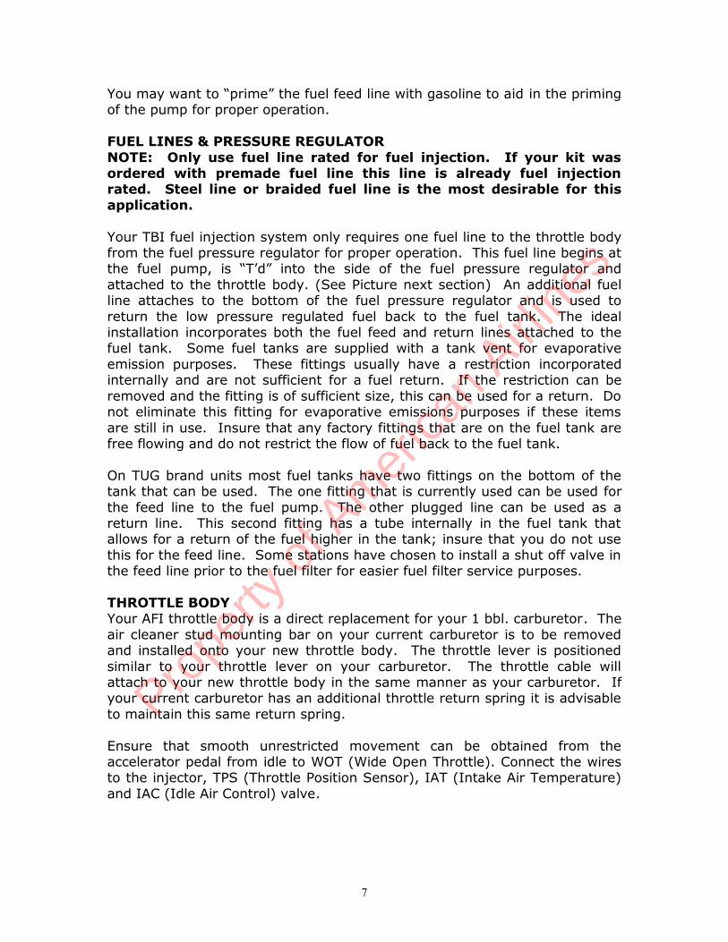
Mount the ECM Bracket in place of the mechanical fuel pump. Note: DO NOT forget gasket
Run the harness trunk along side of motor using cover bolts to bolt down harness as shown below.
Run the portion of harness that goes to the throttle body up using back valve cover bolt and run harness tooutside of intake manifold up towards the throttle body.
Note: Do NOT forget to bolt down the block ground eyelets using provided star washers- Fasten the eyeletsunder the provided clamp using both star washers on the TOP OUTSIDE CORNER of the INTAKE
Manifold.
Prope
rty o
f Am
erica
n Airli
nes
14
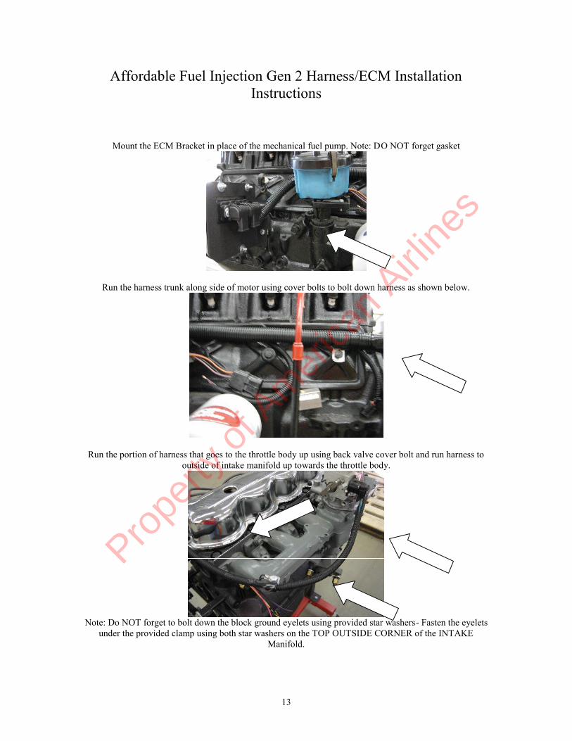
Fuel pump and fuel pressure regulator set up
Preferred MAP sensor orientation
Prope
rty o
f Am
erica
n Airli
nes
15
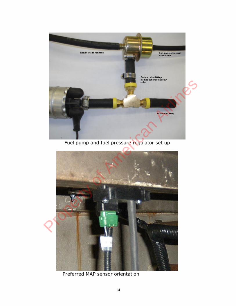
Typical O2 installation when tapped hole is not available in the exhaust manifold. An18mm hole can be drilled and tapped into the standard O2 location in the exhaustmanifold.
De-Icer O2 sensor installation
Prope
rty o
f Am
erica
n Airli
nes
16
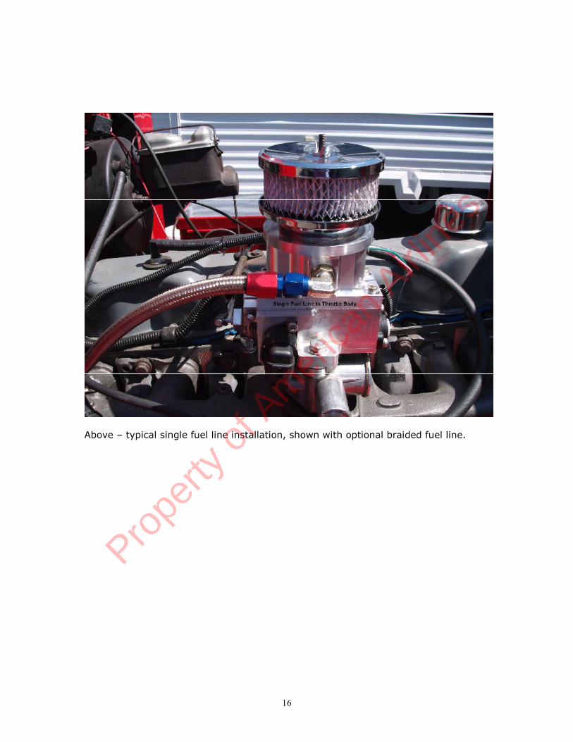
Above – typical single fuel line installation, shown with optional braided fuel line.
Prope
rty o
f Am
erica
n Airli
nes
17
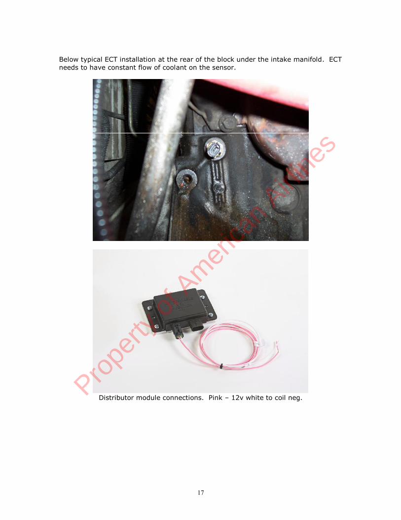
Below typical ECT installation at the rear of the block under the intake manifold. ECTneeds to have constant flow of coolant on the sensor.
Distributor module connections. Pink – 12v white to coil neg.Prope
rty o
f Am
erica
n Airli
nes

18
Component Parts and Part Numbers
Harness * 8510ECM 7203IAT 7303ECT 7302MAP 7300O2 (Heated) 7301H3TPS 7306IAC 7309Throttle body 7610Injector 7660Flange Gasket 7621Fuel Pressure Regulator 7615Fuel Pump 7703Fuel Pump Groundwire harness 8500gndFuel Pump HoldDown Clamp 7703-clRelay 7311hCE Light 7313Low Fuel Light 7315Fuse Link 7314Fuel Filter G7333Distributor 7815Distributor Cap 7815-capDistributor Rotor 7815-rotOil Pressure Sender 7312Fuel Level Sender 7316Distributor Module 7820OBDII Diagnostic Cable 8500OBDII
* Base system
Prope
rty o
f Am
erica
n Airli
nes

19
Troubleshooting your TBI Fuel InjectionSystemQuick Troubleshooting Guide
Connect Scan tool to the engine:Verify proper value of each sensor with Key on Engine Off. TPS 0% MAP 90 – 100 dependent on altitude, will be less at high altitude. ECT consistent with engine temperature whether cold or warm IAT ambient temperature or higher
If any of the above sensors are broadcasting default values work to that problemDefault values are as follows: TPS 10% MAP 40 IAT & ECT 77 deg. F or 25 deg. C.
If engine cranks and will not start unplug the connector from the TPS and attempt tostart. If engine starts repair TPS circuit.
If all the above checks are OK, install fuel pressure gauge. Turn key on and observe fuel pressure. Fuel pump should cycle on and then
off and pressure should be between 50 – 55 psi. If fuel pump does not turnon or pump does not provide full pressure repair fuel system
If pump cycles on and off, determine if pump comes back on when the engineis cranked. Fuel pump should come back on when engine is cranked.
Verify that fuel pressure registers between 42-48 with the engine running andthat the pressure rises with a rapid movement of the throttle. Repair fuelsystem if pressures are not in line or pressure drops on acceleration.
When all of these checks have been made continue to step by step guide to furtherdiagnose operational issues.
Troubleshooting guideMost of the problems encountered while installing your fuel injection system or aftera time of operation are very simple. If your check engine light is on you more thanlikely have a hard fault meaning something is grounded out, unplugged, operatingout of range or has gone bad. See below for how to determine what the fault maybe and code definitions.
With the addition of Fuel Injection to your engine it is important to remember thatthe basics are still there, necessary and have not changed. Batteries must be fullycharged, charging systems fully operational, the ignition system is fully operationaland the integrity of the engine is intact. All of these items are common to an engineand need to be in full operational condition regardless of the fuel system that hasbeen added to your engine.
Prope
rty o
f Am
erica
n Airli
nes
20
The ALDL connector allows for full diagnostics of your unit
If you have installed a Fuel Injection system in your vehicle and are having someinitial issues here is a quick checklist to work from to get you started.
1. Check to make sure your check engine light is not on, or that it is on with thekey on but the engine is not running.
2. Make sure that the red battery wire is connected to a battery source (It ishighly recommended that this wire is connected directly to the battery) andthe pink wire is connected to an ignition 1 source. If your ignition wire is notconnected to an ignition 1 source your ECM will not be powered whilecranking the engine.
3. Check that the ground wire is securely fastened to the block and that theinterface between the block and the terminal is clean.
4. Ensure that there are NO vacuum leaks.5. Ensure that your MAP sensor is connected to a full manifold vacuum source
and not a ported source.6. Set the ignition timing correctly making sure that you have the engine fully
warmed up and operating less than 800 RPM’s.7. Ensure that you have full manifold vacuum routed to your fuel pressure
regulator and there are no vacuum leaks with this connection.8. Check your fuel pressure to ensure that you are providing the proper pressure
to the system.Fuel Pressure is critical for proper operation. Fuel tank mustbe free from debris and fuel pressure needs to be constant andconsistent.Some aftermarket high density fuel filters can cause a large drop in fuel pressureunder load and are not recommended for use with your system. If you are using oneof these types of filters insure that you have proper fuel pressure during all modes ofoperation.
99% of all issues are usually taken care of with one or more of these 8 steps ofdiagnosis.
First and foremost the engine and fuel injection system must be free of vacuumleaks. Vacuum leaks are the leading cause of installation issues with your fuelinjection system. Check all sources of potential vacuum leaks including componentsnot related to the fuel injection system.
There are instances where the vacuum leak is coming from the governor to manifoldmating surface. There are two bolts which bolt the manifold together that in someinstances do not allow the governor to seal to the intake manifold. In some instancesit is necessary to seal these with silicone to provide a positive seal.
Another common issue is a lack of good grounding. Many issues have been resolvedsimply by making sure that the ground path is secure and clean.
Pink Ignition wire MUST be connected to 12 volt switchedignition that receives power during crank and key on.
Prope
rty o
f Am
erica
n Airli
nes

21
Fuel System Checks
Fuel Pressure is critical to the operation of a fuel injection system. Always check toinsure that you have the proper fuel pressure. Fuel pressure should vary betweenabout 42 – 55 PSI. At idle the fuel injection system is typically around 42 – 45 psi.Higher pressure than 55 psi indicates that there is an issue with the installation.Many times this is due to kinked fuel lines, improper routing of the return line and/orfuel line restrictions. (See Part 3 of Troubleshooting guide #3) Many fuel tanks havefittings on them which are used for a fuel tank vent. These fittings are not suitableto use as a return line because they have a restriction in them and restrict the flowof fuel back to the tank. If you have installed your return line to a “vent” line youwill need to route the return line in a different fashion.
Fuel pressure on your Gen II TBI unit should vary between 42 – 55 psi based on theamount of vacuum on the fuel pressure regulator and stay constant under all throttleconditions. There should be an increase in pressure from idle to WOT operation ofthe TBI unit. A pressure drop under this operation indicates a restriction or issuewith the fuel delivery system.
With retrofit fuel injection systems many times we are drawing fuel from gas tanksthat are many years old; hence many years have passed where contamination cansettle into the fuel tank. The electric fuel pump installed for a fuel injection systemwill drawing a greater volume of fuel from your tank than your old system did. Ifthere are any contaminants in the tank this many times will plug up or greatlyrestrict the flow of fuel to the system causing many issues.
Step by Step Troubleshooting guide.Your fuel injection system has been pre calibrated to your particular vehicle. As longas the information about your engine was correctly stated, the system as receivedwill provide many years of trouble free use. However from time to time problemsare encountered with your fuel injection system. Here are a few commonly askedquestions about fuel injection problems. Match the issue # with the chart below foran explanation of the issue and use the troubleshooting fault tree.
Use of this section may require a digital voltmeter, test light, fuel pressure gauge,timing light, tachometer and/or a diagnostic scan tool. If you are familiar withvehicles and how they are serviced you should be able to work through this sectionwith no issues. In many instances you may want to have a professional automotivetechnician familiar with fuel injection repair to help you.
1. My engine cranks but will not start.2. My engine is running to lean, or is backfiring on acceleration.3. My engine is running rich.4. I do not seem to have as much power as I should.5. I am getting a sag when I accelerate.6. My engine takes longer to start than I think it should.7. The fuel pump is not coming on when I first turn the key on.8. The RPM on my engine does not come down when I come to an idle.9. I am not getting as good of fuel economy as I think I should.10.The engine is revving up and down when I come down to an idle.
There is a large “sucking” sound coming from the throttle body when it
Prope
rty o
f Am
erica
n Airli
nes
22
is warmed up. My engine stalls or almost stalls when I come down toan idle.
11. The engine stalls coming to an idle.12. My fuel pump is real noisy.13. My check engine light does not come on when I turn the key on.14.My check engine light is on when the engine is running.15. Engine shuts down and sometimes restarts and sometimes it doesn’t.
1. Engine cranks but will not start.
There is an assumption that the battery is at a full state of charge, the fuel tank has fuelin it and that all sensors are correctly connected and there are no trouble codes in the ECM.
1. Does the injector spray fuel when cranking the engine?
Yes – Go to step 2.No – Disconnect the TPS sensor and determine if the vehicle starts, injector sprays.
If engine starts or injector sprays, repair TPS circuit.If injector does not spray move to the next “NO” step.
No - Remove the injector connector from the injector. With a voltmeter or test light measurethe voltage or validate power to the pink wire of the connector with the key on.
Yes – Pink wire has voltage, go to step 1a.No – There is no power getting to the system. Check for proper connection to the
battery, fuses are good, relays have been connected and seated properly. Correct the powerissue; if there is still no fuel spray when cranking the engine after this has been corrected go tostep 1a.
1a. With the voltmeter or test light still connected crank the engine and verify voltage tothe pink wire on the injector connector.Results:“0” volts or the light goes out when cranking the engine.
The primary (pink) ignition wire is incorrectly connected to thevehicle. This is to be an ignition 1 (ING1) source which is powerin both the key run and crank position. Correct the connection ofthis wire and verify voltage to the pink wire on the injectorconnector. Test again for fuel spray during crank. If the enginestill cranks, is spraying fuel, but will not start go to step 2.
“Low volts, < 8” This is an indication of either a battery in a state of verylow charge, a bad battery or too much resistance in the system.-record the battery voltage while cranking at the battery.-record the voltage at the pink wire of the injector connector while
cranking the engine.-compare these two voltages, they should be within .2 (2/10) volts
of each other. If these voltages are greater than .2 there is a badconnection or too much resistance in the wire feeding the ECM.
-Correct the issue with low voltage. If cranking voltage is above 9volts while cranking and there is still no fuel spraying the issue isin the fuel delivery system.
“9 volts or higher” this is normal cranking voltage. If there is no fuelspraying while cranking the issue is in the fuel delivery system orignition system Trouble shoot the fuel system for improper operation(See Fuel System checks at the beginning of this guide). Troubleshootignition system, go to 1b.
Prope
rty o
f Am
erica
n Airli
nes

23
1b. Your TBI fuel injection system fueling is “triggered” from the ignition system. It isassumed that the coil is operational, a 12 volt ignition 1 (IGN1) source is connected tothe positive terminal of the coil.
Remove plug wire and check for spark while cranking.No Spark – Repair ignition system.
Has spark – Insure wire continuity between the ECM and the distributor . If fuelis still not spraying go to fuel system troubleshooting before replacing any components.If all wires are in tact and routed correctly and all fuel system checks are correct, replacedistributor module.
2. Perform the fuel system checks found at the beginning of this troubleshootingGuide. If the fuel pressure and fuel system are operating as required Insure that thecheck engine light is on with the key on but the engine not running and there are nostored codes.If you have installed a new distributor, removed the distributor for any reason yourignition timing may be off too much to operate the engine properly. Disconnect theconnector from the injector and set the ignition timing to its proper setting whilecranking the engine. Assumption here also is that the timing mark on the balancer islined up with TDC of #1 cylinder and that the distributor is seated properly and not 180degrees off. If all of this checks OK go to step 3.
3. Measure the voltage on the throttle position sensor. If using a scan tool you can readTPS, if not measure the voltage. To measure the throttle position voltage check betweenthe brown wire and the black/white striped wire on the TPS with the TPS still connectedand the key on. DO NOT PUNCTURE THE WIRES to measure this voltage and only use adigital voltmeter. Voltage can be measured by back probing the TPS connector betweenthese wires either with a thin paper clip or appropriate tool used for this type ofmeasurement. Voltage should be between .5 volts and .7 volts.
If you have gone through all of the above procedures and the engine still willnot start you will need to call tech support. When you call tech support youwill need to have the following information available.
Fuel pressure at the inlet of the TBI unit________________________________Return line fuel pressure____________________________Voltage measured at the battery while cranking___________Voltage measured at the pink wire on the injector while cranking____________Voltage measured at the TPS sensor key on engine off_____________________Codes stored in the ECMAny information that you feel is important for diagnosing the issue at hand.
2. My engine is running to lean, or is backfiring onacceleration.
Assumption here is that all plug wires are installed properly, the secondary ignitionsystem (plug wires, coil, cap and rotor) is in good operating order and the engine isin good order.
Perform fuel system checks found at the beginning of this guide and make anycorrections as necessary.
Prope
rty o
f Am
erica
n Airli
nes
24
Check initial ignition timing again.
If the timing is OK check to insure that the timing is advancing as it should withthrottle lever actuation.
If the fuel system checks performed are OK and the initial ignition timing is OKyou will need to call tech support.
If you have gone through all of the above procedures and the engineis still running lean or is backfiring on acceleration you will need tocall tech support. In many cases the specifications of the engine aredifferent than what was originally discussed or assumed. When youcall tech support you will need to have the following informationavailable.
Fuel pressure at idle________________________________Fuel pressure while briefly accelerating the engine to WOT_____________Return line fuel pressure____________________________Voltage measured at the battery while running___________Engine operational temperature_______________________Initial ignition timing_____________________Timing at 2000 RPM_____________________Any information that you feel is important for diagnosing the issue at hand.
3. Engine runs too rich.
Check for vacuum leaks and insure that all vacuum leaks are corrected and sealed. If the engineis also running at a higher than expected idle this is a good indication of a vacuum leak as well.
1. Is the vacuum line to the MAP sensor securely fastened to both the MAPsensor port and a full manifold vacuum port on the intake manifold?
Yes, If engine is still running rich go to step 2.No – Repair leak, kink or routing, is engine still running rich? If yes go to step 2.
3. Is the MAP sensor connected to a full manifold vacuum port?
Yes – If engine is still running rich go to step 3.No – Correct the vacuum source issue, if the engine is still running rich go to step 3.
3. Is the fuel pressure measured at 42 - 55 psi while running?
Yes – If the engine is still running rich go to step 4.No – Is the return line connected to an unrestricted return port on the fuel tank?
Many fuel tanks have a port on the fuel tank that is for a fuel vent. These portsare not adequate for a fuel return. There is an orifice in these ports that willrestrict the flow of fuel. Check that you have not used a vent port for the fuelreturn line.
No – Go to step 3a.Yes – Fuel is being returned to a vent line. Re-route fuel return line to a non
Prope
rty o
f Am
erica
n Airli
nes
25
orificed port or fabricate a free flowing return line port to the fuel tank or fuelreturn. If still running rich go to step 3a.
3a. Measure return line fuel pressure. This pressure should be less than 3 psi, ifnot there is a restriction in the return fuel line. If return fuel line pressure is lessthan 3 psi and the engine is still running rich go to step 4.If return line pressure is not less than 3 psi there is a restriction in the fuel lineFind and repair the restriction until the fuel pressure on the return line is less than3psi. In some cases this requires a larger diameter fuel return line. Go to step 3bto help determine root cause of increased return line pressure.
3b. Remove the fuel return line and attach a length of rubber hose of sufficientlength to run into an approved gasoline container. Run engine and recheck fuelpressure on both the feed side and the return side. If both sides are within theabove ranges there is a restriction in the fuel delivery system that needs to berepaired.
4. Does the engine have a fully operational thermostat?
Yes – insure that the engine will reach 190 deg. in a reasonable time, go to step 5.No – Install new thermostat, proper size thermostat will be 190- 195. 160 or 180 degreethermostat is not acceptable for this application and will not comply with AFI warranty oremissions requirements. If still running rich go to step 5.
5. Is the coolant sensor installed in a portion of the engine or the cylinderblock which provides a constant flow of coolant over the tip of the sensor?
Yes –Go to step 6.No – Reinstall the coolant sensor in a different location to insure constant flow of coolant overthe sensor. If still running rich go to step 6.
6. Is the charging system operating properly and is the voltage measured atthe battery and the injector 13 volts or higher with the engine running?
Yes – Go to step 7.No – Repair charging system. Note the discussion about older style AC Delco single wirealternators. If still running rich after reparing go to step 7.
7. If you have gone through all of the above procedures and the engine is stillrunning rich you will need to call tech support. In many cases thespecifications of the engine are different than what was originallydiscussed or assumed. When you call tech support you will need to havethe following information available.
Fuel pressure at idle________________________________Return line fuel pressure____________________________Voltage measured at the battery while running___________Voltage measured at the pink wire on the injector while cranking.Engine RPM at start up idle on a cold start___________________________Engine RPM at idle with stabilized temperature_______________________Engine operational temperature_______________________Initial ignition timing_____________________Any information that you feel is important for diagnosing the issue at hand.
Prope
rty o
f Am
erica
n Airli
nes

26
4. I do not seem to have as much power as Ishould.
Verify that you have set your timing properly, timing should be set to 12 deg. BTDCwith the engine fully warmed up and RPM below 800.
Verify that the timing mark for TDC of #1 cylinder that is being used to set thetiming lines up properly with TDC of #1 cylinder (#1 piston at TDC with spark plugremoved).
Ensure that your plug wires are properly connected with the correct firing order.
Your fuel pressure may be insufficient; see fuel system checks at the beginning ofthis guide.
Verify that there are no vacuum leaks and that the MAP sensor is properlyconnected.
5. I am getting a sag when I accelerate.
Insure that the MAP sensor and TPS sensor are working properly with scan tool.Default values for MAP and TPS are a single value and can cause a sag if notoperating properly.
Timing is a critical issue with sags. Verify that your timing is correctly. see #4 also.
Fuel pressure is not adequate for proper operation, make sure that there is nocontamination in the tank or your fuel filter is plugged. (See Fuel System checkabove). A plugged fuel filter may be an indication of a contaminated tank.
Bad ground to the block, insure that the surface that you are making the connectionto on the block is clean and making a positive connection.
Your O2 sensor may be contaminated, bad or not properly installed in the exhaust.
You may have left out some of the important specifications for the proper calibrationchip to be made.
If you have gone through all of the above procedures and the engineis still sagging on acceleration you will need to call tech support. Inmany cases the specifications of the engine are different than whatwas originally discussed or assumed. When you call tech support youwill need to have the following information available.
Fuel pressure at idle________________________________Fuel pressure when throttle is blipped to WOT ______________________Return line fuel pressure____________________________Voltage measured at the battery while running___________Voltage measured at the pink wire on the injector while cranking.Engine RPM at start up idle on a cold start___________________________Engine RPM at idle with stabilized temperature_______________________Engine operational temperature_______________________
Prope
rty o
f Am
erica
n Airli
nes

27
Initial ignition timing_____________________Any information that you feel is important for diagnosing the issue at hand.
6. My engine takes longer to start than I think itshould.
Check for vacuum leaks, this is the most common cause.
Make sure that your timing is set correctly; see Troubleshooting point #4.Fuel pressure is not adequate for proper operation. See Fuel System Checks at thebeginning of this guide.
Fuel pump relay is not coming on or is faulty.
Check that the MAP sensor is properly connected to a full manifold vacuum source.Ensure that the vacuum source to your MAP sensor is free from restrictions and hasa secure connection.
Throttle plates are not adjusted properly not allowing an adequate amount of air forstarting the engine. Go to Troubleshooting guide #10 and verify the adjustment.
Throttle position sensor is out of adjustment or faulty. Throttle position voltage withthrottle fully closed with the key on should be .5 volts + .2 volts.
If you have gone through all of the above procedures and the engineis still sagging on acceleration you will need to call tech support. Inmany cases the specifications of the engine are different than whatwas originally discussed or assumed. When you call tech support youwill need to have the following information available.
Fuel pressure at idle________________________________Voltage measured at the battery while running___________Voltage measured at the pink wire on the injector while cranking_____________Voltage measured between the black wire and brown wire on the TPS with the keyon engine not running__________________Engine RPM at start up idle on a cold start___________________________Engine RPM at idle with stabilized temperature_______________________Engine RPM at idle with IAC fully blocked off.___________________IAC counts at stabilized idle in drive if using a scan tool____________________Engine operational temperature_______________________Initial ignition timing_____________________Any information that you feel is important for diagnosing the issue at hand.
7. The fuel pump is not coming on when I firstturn the key on.
Is the check engine light on with the key on engine off? (Assumes check engine lightis connected properly, see installation instructions to verify check engine lightinstallation)
Prope
rty o
f Am
erica
n Airli
nes

28
Yes - Go to step 1.No – Check for proper installation of check engine light.
a. Check fuses to insure that they are not blown. If fuses are OK go to b.b. Check voltage at check engine light, if 12 volt are not present the
check engine light is not connected properly. If 12 volts are presenteither the ECM is not powered properly or is defective.
1. Insure that the IGN1 wire is not connected to a battery feed.a. Check pink wire to the power relay and/or the pink wire powering up the
injector(s) to insure there is no voltage with the key off. If voltage is presentwith the key off the pink wire is not properly connected or the power relay isbad.
a. Check fuel pump relay for proper operation. Turn ignition off for at least 15 seconds. Connect an ohmmeter or test light to the blue wire at the fuel
pump relay. Turn ignition on, a ground signal should be present at this wire
for the first 2 or 3 seconds after turning on the ignition switch. If ground is not present either the ECM is not powered or
grounded properly or the ECM is faulty. If ground is present check for voltage at the fuel pump with the
same type of operation. If voltage is not present at the fuel pump check the wiring, if
wires appear to be OK replace the fuel pump relay. If voltage is present verify the ground for the fuel pump is
sufficient and securely fastened. If fuel pump ground is OK thefuel pump is defective.
If you have gone through all of the above procedures and the fuelpump is still not coming on when you turn the key on you will need tocall tech support. When you call tech support you will need to havethe following information available.
Voltage measured at the check engine light with key on engine off___________Voltage measured at the pink wire on the injector while cranking_____________Voltage measured at the pink wire on the injector with the key off_____________Ohms measured at the blue wire at the fuel pump relay at first 3 seconds of the keyon_____________Voltage measured at the pink wire to the fuel pump at the first 3 seconds of the keyon_____________Voltage measured with voltmeter between the black wire and pink wire on the fuelpump for the first 3 seconds of the key on_____________Any information that you feel is important for diagnosing the issue at hand.
8. The RPM on my engine does not come downwhen I come to an idle.
More than likely you have a large vacuum leak, verify that yoursystem is free from vacuum leaks.
Check that all non used vacuum ports are plugged. Your ignition wire is connected to a battery source and not an
ignition 1 source. The engine has not come to full operating temperature as of yet.
Prope
rty o
f Am
erica
n Airli
nes
29
Your thermostat is inoperable or opens at too low of atemperature. A 190o stat is required for this application.
Throttle cable or throttle on the throttle body is not coming to acomplete close. Throttle plate is binding in the throttle bores.
The throttle plates are adjusted too far out, see procedure #10 forproper adjustment sequence.
IAC is not working, either faulty or there is a wiring issue.i. Shut engine off and wait for 20 secondsii. Unplug IAC connector from IACiii. Start up engine, RPM should be significantly higher than the
base RPM. If the engine RPM did not increase the IAC isbad or the wiring is faulty to the IAC or the ECM is bad.
If you have gone through all of the above procedures and the engineis still idling too high you will need to call tech support. When youcall tech support you will need to have the following informationavailable.
Voltage measured between the black wire and brown wire on the TPS with the keyon engine not running__________________Engine RPM at start up idle on a cold start___________________________Engine RPM at idle with stabilized temperature_______________________Engine RPM at idle with IAC fully seated or blocked off.___________________IAC counts at stabilized idle in drive if using a scan tool____________________Engine operational temperature_______________________Initial ignition timing_____________________Any information that you feel is important for diagnosing the issue at hand.
9. I am not getting as good of fuel economy as Ithink I should.
If all is set up properly with the installation of your fuel injection system you areprobably getting as good of fuel economy as you are going to get.
1. Insure that your timing is set properly2. Your thermostat is in good working order and is 190 degree or above.3. Your fuel pressure is at the specified pressure (see fuel system check at
the beginning of this guide.4. You may have other factors such as tires, brake drag or other external
issue from the fuel injection system that is not working properly.5. Re-evaluate your driving habits and insure that you are driving in a
fashion that will provide you optimum fuel economy. If you are trying torace everyone from the light chances are you will not get the fueleconomy that you expect.
If you have gone through all of the above procedures and you stillfeel that you should be getting better fuel economy you will need tocall tech support. In many cases the specifications of the engine aredifferent than what was originally discussed or assumed. When youcall tech support you will need to have the following informationavailable.
Prope
rty o
f Am
erica
n Airli
nes
30
What is the Fuel Economy that you aregetting________________________________What is the Fuel Economy that you areexpecting________________________________Voltage measured at the battery while running___________Voltage measured between the black wire and brown wire on the TPS with the keyon engine not running__________________Engine RPM at idle with stabilized temperature_______________________Engine operational temperature_______________________Initial ignition timing_____________________Trouble Codes from the ECM (see #14)______________Any information that you feel is important for diagnosing the issue at hand.
10. The engine is revving up and down when Icome down to an idle. There is a large“sucking” sound coming from the throttle bodywhen it is warmed up. My engine stalls oralmost stalls when I come down to an idle.
This is usually an indication of a vacuum leak; again make sure that you have novacuum leaks.
This could also be an indication of the wrong base ignition timing. Verify that youhave set your ignition timing correctly (see #4).
Your engine may also require more air going through the throttle plates at idle thanit is currently set for. Here is a procedure to check this setting.
a. Make sure your engine temperature is at full operating temperature.b. Plug the IAC passage on the inside of the throttle body with a piece of tapeor you finger and unplug the IAC connector from the IAC.c. Check that the RPM is 775 – 800 in neutral with the engine fully warmedup. Adjust as necessary, re-install the IAC connector, remove the tape if youtaped over the IAC port and turn the engine off.d. Wait for 30 seconds with the key turned off and then restart the engine.e. If you have a fast idle after 1 minute of operation this did not work or youhave a vacuum leak that is not repaired, or the throttle plates are already toofar open. You may have to go through the procedure again.f. If you do not have a fast idle then it is OK and you can proceed todetermine if the plates are adjusted properly. Let the engine idle for a littlebit and then check your idle speed in drive. The speed should be about 625in drive. If it is lower than this you can raise the idle up or if it is above thisdetermine if you should bring the speed down.
If you have gone through all of the above procedures and the engineis still idling too high you will need to call tech support. When youcall tech support you will need to have the following informationavailable.
Voltage measured between the black wire and brown wire on the TPS with the keyon engine not running__________________Engine RPM at start up idle on a cold start___________________________
Prope
rty o
f Am
erica
n Airli
nes

31
Engine RPM at idle with stabilized temperature_______________________Engine RPM at idle with IAC fully seated or blocked off.___________________IAC counts at stabilized idle in drive if using a scan tool____________________Engine operational temperature_______________________Initial ignition timing_____________________Any information that you feel is important for diagnosing the issue at hand.
11. The engine stalls coming to an idle.
Verify all ignition system components are operating properly, including cap, rotor,secondary ignition wires and coil.
Verify that the IAC is operating properly. Shut engine off and wait for 20 seconds Unplug IAC connector from IAC
Start up engine, RPM should be significantly higher than the base RPM. If the engineRPM did not increase the IAC is bad or the wiring is faulty to the IAC or the ECM isbad. Repair as necessary.
Verify proper fuel pressure, perform above fuel system checks.
Verify timing is proper
Verify that the EGR is working properly and not sticking. (if equipped)Sticking EGR valve will cause a stall.
12. My fuel pump is real noisy.
If your fuel pump is real noisy you may not have isolated it from the body or theframe real well. Isolation brackets were provided with your fuel pump. If these areproperly installed it should isolate any radiated noise from the pump. If this isinsufficient you may need to isolate it more with some rubber grommets.
We have also diagnosed noisy fuel pumps with fuel return lines being too small. Bystepping up the size of the return line you may eliminate fuel pump noise after theother items have been addressed. Fuel pump noise also can radiate through the fuellines to the frame or body of the vehicle. Insure that the fuel lines are isolated aswell if need be to eliminate the noise.
A noisy fuel pump can also be an indication that it is starving for fuel. Insure that allfilters are in good order and that the fuel tank sock is clean. Prolonged fuelstarvation will damage the fuel pump and not allow proper flow; it may also radiate alot of noise.
13. My check engine light does not come on when Iturn the key on.
Your check engine light should illuminate when you turn the key to the on positionfor a bulb check.Check for proper installation of check engine light.
a. Check fuses to insure that they are not blown. If fuses are OK go to b.
Prope
rty o
f Am
erica
n Airli
nes
32
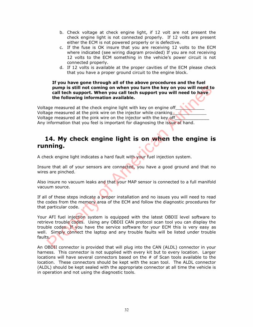
b. Check voltage at check engine light, if 12 volt are not present thecheck engine light is not connected properly. If 12 volts are presenteither the ECM is not powered properly or is defective.
c. If the fuse is OK insure that you are receiving 12 volts to the ECMwhere indicated (see wiring diagram provided) If you are not receiving12 volts to the ECM something in the vehicle’s power circuit is notconnected properly.
d. If 12 volts is available at the proper cavities of the ECM please checkthat you have a proper ground circuit to the engine block.
If you have gone through all of the above procedures and the fuelpump is still not coming on when you turn the key on you will need tocall tech support. When you call tech support you will need to havethe following information available.
Voltage measured at the check engine light with key on engine off___________Voltage measured at the pink wire on the injector while cranking_____________Voltage measured at the pink wire on the injector with the key off_____________Any information that you feel is important for diagnosing the issue at hand.
14. My check engine light is on when the engine isrunning.
A check engine light indicates a hard fault with your fuel injection system.
Insure that all of your sensors are connected, you have a good ground and that nowires are pinched.
Also insure no vacuum leaks and that your MAP sensor is connected to a full manifoldvacuum source.
If all of these steps indicate a proper installation and no issues you will need to readthe codes from the memory area of the ECM and follow the diagnostic procedures forthat particular code.
Your AFI fuel injection system is equipped with the latest OBDII level software toretrieve trouble codes. Using any OBDII CAN protocol scan tool you can display thetrouble codes. If you have the service software for your ECM this is very easy aswell. Simply connect the laptop and any trouble faults will be listed under troublefaults.
An OBDII connector is provided that will plug into the CAN (ALDL) connector in yourharness. This connector is not supplied with every kit but to every location. Largerlocations will have several connectors based on the # of Scan tools available to thelocation. These connectors should be kept with the scan tool. The ALDL connector(ALDL) should be kept sealed with the appropriate connector at all time the vehicle isin operation and not using the diagnostic tools.
Prope
rty o
f Am
erica
n Airli
nes

33
15. Engine shuts down and sometimes restarts andsometimes it doesn’t.
Your AFInjection system is equipped with several integrated automatic shutdownfeatures. Some are standard and others are optional. Each shut down will set a DTCand store the code in the ECM. Insure that you clear any code after diagnosing thatyour issue was an automatic shut down feature.The shut down features are as follows:
High engine coolant shut down. (standard)The ECM will cause the engine to shut down if the temperature reaches 238
deg F. It will not run until the temperature is below 234 deg F. A code P0217 will set under this condition. Insure that you clear the code if this code has been present. This same condition will be present if the ECT is defective. If your vehicle is continually setting this code and/or shutting down,
determine the cooling system issues which are causing it and repairaccordingly.
Engines need to be equipped with the proper size radiator, fan and a fanshroud to provide proper cooling.
Low Oil Pressure Shut Down (optional, standard with complete engines)The ECM will cause the engine to shut down if the oil pressure falls to a
dangerous level. A bypass switch is not required for this operation. The enginehowever will start and run for a few seconds when a low oil pressure condition exists.
A code P0521 will set under this condition. Determine the cause of the low oil pressure and repair as necessary. Insure that you clear the if this code has be present. An unplugged Oil Pressure Sensor will also cause this condition and set a code
P0522 will set.
Low Fuel Shut Down (optional)The ECM along with a fuel level sensor will shut the engine down and not
allow a re crank of the engine if the fuel falls below 10 - 15% fill. This feature isincorporated to reduce damage which can be caused to the electric fuel pump if thevehicle is run out of fuel.
A red light installed on the dash panel will illuminate when the fuel tankbegins to get below 25%. At first the light will flash on and off at irregular intervalsstaying off longer than it stays on and the staying on longer than it stays off if thevehicle is not refueled.
At one point the light will come on and stay on at which time a 30 minutetimer will begin to count up. Turning off the vehicle will not clear the timer. If after20 minutes of operation with the low fuel light on the vehicle is not refueled the lightwill begin to flash. At this point also the rev limiter on the engine may be reduced to2000 RPM. If the vehicle is still not serviced after 10 minutes of operation with thelow fuel light flashing the ECM will shut the engine down. When equipped with“Smart Start” the engine will not crank at this time either so that the operator doesnot damage the starter and the ring gear on the transmission from cranking with nostart.
The only way to correct this condition is to fill the tank up. Once the tank isfilled up you may have to wait 10 seconds or so with the ignition turned on to clearthe timer and allow for normal operation again.
Prope
rty o
f Am
erica
n Airli
nes
34
Low Fuel Level will set a code P1462 and store it in the ECM. Clear this code if youhave it stored in the ECM. This will also tell you how the operators are using theequipment.
Smart Start (optional)This feature controls the engine cranking through the ECM. Used with Low
Fuel Shut Down and other shut down features as a feature to not do damage to theengine or other components on the engine.
Smart start does not allow the engine to crank under the adverse conditionsand/or does not allow the engine to crank for more than 10 seconds if it does notstart.
Simply turning the key off and back on resets everything and allows theengine to crank unless it is in a protection mode.
Unattended Idle Shut Down (optional)This feature will shut the engine down if it is left running at idle for a
predetermined period of time. This will allow for compliance with regulatoryagencies for length of idle time or to increase the fuel economy of the vehicle. Thefeature is also temperature activated so that the engine will be allowed to fully warmup before this feature is activated.
Prope
rty o
f Am
erica
n Airli
nes
35
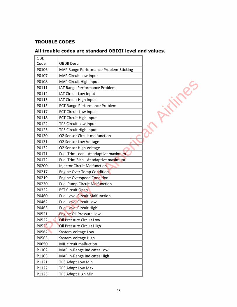
TROUBLE CODES
All trouble codes are standard OBDII level and values.OBDIICode OBDII Desc.P0106 MAP Range Performance Problem-StickingP0107 MAP Circuit Low InputP0108 MAP Circuit High InputP0111 IAT Range Performance ProblemP0112 IAT Circuit Low InputP0113 IAT Circuit High InputP0115 ECT Range Performance ProblemP0117 ECT Circuit Low InputP0118 ECT Circuit High InputP0122 TPS Circuit Low InputP0123 TPS Circuit High InputP0130 O2 Sensor Circuit malfunctionP0131 O2 Sensor Low VoltageP0132 O2 Sensor High VoltageP0171 Fuel Trim Lean - At adaptive maximumP0172 Fuel Trim Rich - At adaptive maximumP0200 Injector Circuit MalfunctionP0217 Engine Over Temp ConditionP0219 Engine Overspeed ConditionP0230 Fuel Pump Circuit MalfunctionP0322 EST Circuit OpenP0460 Fuel Level Circuit MalfunctionP0462 Fuel Level Circuit LowP0463 Fuel Level Circuit HighP0521 Engine Oil Pressure LowP0522 Oil Pressure Circuit LowP0523 Oil Pressure Circuit HighP0562 System Voltage LowP0563 System Voltage HighP0650 MIL circuit malfuctionP1102 MAP In-Range Indicates LowP1103 MAP In-Range Indicates HighP1121 TPS Adapt Low MinP1122 TPS Adapt Low MaxP1123 TPS Adapt High Min
Prope
rty o
f Am
erica
n Airli
nes

36
P1124 TPS Adapt High MaxP1131 O2 In-Range Indicates LowP1132 O2 In-Range Indicates HighP1201 Injector PW OverflowP1220 Medium engine overspeedP1241 Output Voltage Range LowP1242 Output Voltage Range HighP1350 EST Bypass Circuit OpenP1460 Fuel Level Is LowP1461 Fuel Level is nearing emptyP1462 Fuel Level is Empty-engine shut downP1478 Fan Circuit MalfunctionP1506 IAC FaultP1507 IAC FaultP1655 Smart Start circuit malfunction
P0106 MAP sticking, voltage not changing.P0107 Low voltage (high vacuum) at MAP sensor.P0108 High voltage (low vacuum) at MAP sensor.P1103 MAP in range error high.P1102 MAP in range error low.P0111 IAT in range error. IAT has failed but is not an open or shorted
circuit.P0112 IAT Low, Sensor could be unplugged Resistance will be high with
this issue.P0113 IAT High, Sensor could be grounded out. Resistance will be low
with an issue.P0115 ECT in range error. ECT has failed but is not an open or shorted
circuit. An ECT not installed in the proper location can cause thiscode also. A bad or weak thermostat can also cause this code.
P0117 ECT Low, sensor can be unplugged, engine will run very rich withthis issue. Resistance will be high or open circuit.
P0118 ECT High, sensor can be shorted or bad and engine will run lean withthis issue. Bad sensor will have low risistance.
P0217 ECT over temperature. Set when engine is over 248 deg. F (120deg. C). Overheating of the engine causes this code.
P0122 Low voltage at throttle positon sensorP0123 High voltage at throttle positon sensor. Sensor could be unplugged.P1121 TPS adjusted at too low of a voltage.P1122 TPS adjusted at too high of a voltage.P1123 TPS not reaching high enough voltage.P1124 TPS voltage too high at part throttle.P0130 Oxygen sensor signal stays lean during warm engine cruise, your O2
sensor could be unplugged.
Prope
rty o
f Am
erica
n Airli
nes
37
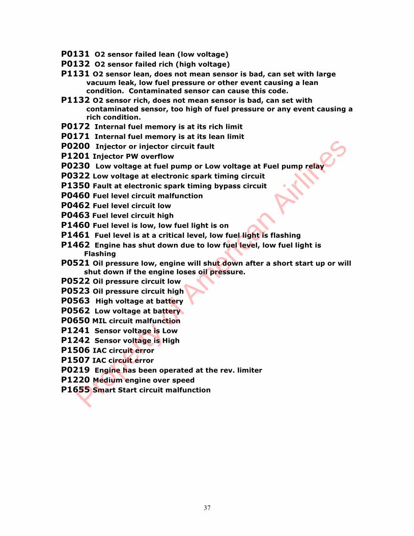
P0131 O2 sensor failed lean (low voltage)P0132 O2 sensor failed rich (high voltage)P1131 O2 sensor lean, does not mean sensor is bad, can set with large
vacuum leak, low fuel pressure or other event causing a leancondition. Contaminated sensor can cause this code.
P1132 O2 sensor rich, does not mean sensor is bad, can set withcontaminated sensor, too high of fuel pressure or any event causing arich condition.
P0172 Internal fuel memory is at its rich limitP0171 Internal fuel memory is at its lean limitP0200 Injector or injector circuit faultP1201 Injector PW overflowP0230 Low voltage at fuel pump or Low voltage at Fuel pump relayP0322 Low voltage at electronic spark timing circuitP1350 Fault at electronic spark timing bypass circuitP0460 Fuel level circuit malfunctionP0462 Fuel level circuit lowP0463 Fuel level circuit highP1460 Fuel level is low, low fuel light is onP1461 Fuel level is at a critical level, low fuel light is flashingP1462 Engine has shut down due to low fuel level, low fuel light is
FlashingP0521 Oil pressure low, engine will shut down after a short start up or will
shut down if the engine loses oil pressure.P0522 Oil pressure circuit lowP0523 Oil pressure circuit highP0563 High voltage at batteryP0562 Low voltage at batteryP0650 MIL circuit malfunctionP1241 Sensor voltage is LowP1242 Sensor voltage is HighP1506 IAC circuit errorP1507 IAC circuit errorP0219 Engine has been operated at the rev. limiterP1220 Medium engine over speedP1655 Smart Start circuit malfunction
Prope
rty o
f Am
erica
n Airli
nes
38
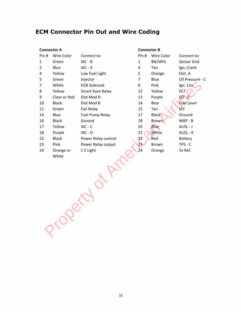
ECM Connector Pin Out and Wire Coding
Connector A Connector BPin # Wire Color Connect to: Pin # Wire Color Connect to:1 Green IAC - B 1 Blk/Wht Sensor Gnd2 Blue IAC - A 4 Tan Ign, Crank4 Yellow Low Fuel Light 5 Orange Dist. A5 Green Injector 7 Blue Oil Pressure - C7 White EGR Solenoid 8 Pink Ign. 12v8 Yellow Smart Start Relay 12 Yellow ECT9 Clear or Red Dist Mod D 13 Purple O2 - C10 Black Dist Mod B 14 Blue Fuel Level11 Green Fan Relay 15 Tan IAT14 Blue Fuel Pump Relay 17 Black Ground16 Black Ground 18 Brown MAP - B17 Yellow IAC - C 20 Blue ALDL - J18 Purple IAC - D 21 White ALDL - K22 Black Power Relay control 22 Red Battery23 Pink Power Relay output 23 Brown TPS - C24 Orange or C E Light 24 Orange 5v Ref.
White
Prope
rty o
f Am
erica
n Airli
nes

Start
Relay
B22BATT
B8KEY_SW
B5VR_DG1+
B6VR_DG1-
B10VR_DG2+
B11VR_DG2-
B24XDRP
B1XDRG
B18AN1 (51K1 GND)
B23AN2 (220K GND)
B4AN3 (220K GND)
B7AN4 (220K GND)
B16AN5 (220K GND)
B2AN6 (220K GND)
B3AN7 (220K GND)
B12AN8 (2K2 5V)
B15AN9 (2K2 5V)
B14AN10 (2K2 5V)
B13AN11
B19AN12
B9AN13
B20CAN1+
B21CAN2+
A22MRPD
A23DRVP
A5LSO/INJ-1
A8LSO/INJ-2
A4LSO/INJ-3
A7LSO/INJ-4
A13LSO5
A14LSO6
A20LSO7/ TACH_LINK
A11LSO8
A24LSO9
A17H-BRIDGE1A
A18H-BRIDGE1B
A1H-BRIDGE2A
A2H-BRIDGE2B
A9(5V) EST1
A10(5V) EST2
A3(5V) EST3
A6(5V) EST4
A19(5V) EST5
A21(5V) EST6
A12(5V) EST7
A15(5V) EST8
A16GND
B17GND
PowerRelay
BatterySaver
PowerRelay
BatterySaver
INJ Start
RelayNeutralSafetyStarterRelay
LowFuel
FUELPUMP
RELAY
Fan
Relay
CE
-
Coil
+
IgnitionSwitch
Crank
ECT
IAT
IAC
ABCD
MAPA
CB
TPSA
CB
OilPres
A
CB
Battery+ -
+12V
+12V
+12VFUELPUMP
FAN
DISTMOD
ABCD
BA
DISTA
CB
Fuel
Sender
O2A
CB
ALDLOBDIICon
16
54
614
Non-Certified 4.9L EngineWire Diagram
Prope
rty o
f Am
erica
n Airli
nes


