GS-FLANGE SYSTEM CLAMPS VALVES ADAPTORS OTHER COMPONENTS MACHINES BITE TYPE FITTINGS HOSES & COUPLINGS SAE J514 JIC PIPES & TUBES SWIVELS QUICK DISCONNECT TEST EQUIPMENT 483 GENERAL INFORMATION General information Process Design .......................................................................484 Mechanical Design ................................................................485 Attachments Pressure drop in pipes ...........................................................488 Pressure drop in bends, couplings, etc.................................489 Oil flow rates at recommended max. velocities ..................490 Recommended connection technology – 50 bar .................491 Recommended connection technology – 210 bar ...............492 Recommended connection technology – 280 bar ...............493 Recommended connection technology – 350 bar ...............494 Recommended connection technology – 420 bar ...............495 Hose size selection nomogram .............................................496 Pressure drop in hoses ..........................................................497 Bending radius theory for hoses ..........................................498 Spacing for clamps ................................................................499 Linear expansion of steel pipes ............................................500 Thread identification ............................................................501 Cleanliness..............................................................................502 This technical information is provided as general guidelines how to design hydraulic piping systems. In the design of a specific piping system the environment, the customers specifications as well as local rules, regulations and laws must be followed at all times.
Transcript
GS-
FLA
NG
ESY
STEM
CLA
MpS
VALV
ESA
dA
pTo
rSo
THEr
Co
Mpo
NEN
TSM
ACH
iNES
BiTE
TYp
E Fi
TTiN
GS
Ho
SES
&
Cou
pLiN
GS
SAE
J514
JiC
pi
pES
& T
uBE
SSW
iVEL
SQ
uiC
K
diS
CoN
NEC
TTE
ST
EQu
ipM
ENT
483
GEN
ErA
LiN
ForM
ATio
N
General information
Process Design .......................................................................484Mechanical Design ................................................................485AttachmentsPressure drop in pipes ...........................................................488Pressure drop in bends, couplings, etc. ................................489Oil flow rates at recommended max. velocities ..................490Recommended connection technology – 50 bar .................491Recommended connection technology – 210 bar ...............492Recommended connection technology – 280 bar ...............493Recommended connection technology – 350 bar ...............494Recommended connection technology – 420 bar ...............495Hose size selection nomogram .............................................496Pressure drop in hoses ..........................................................497Bending radius theory for hoses ..........................................498Spacing for clamps ................................................................499Linear expansion of steel pipes ............................................500Thread identification ............................................................501Cleanliness..............................................................................502
This technical information is provided as general guidelines how to design
hydraulic piping systems. In the design of a specific piping system the
environment, the customers specifications as well as local rules, regulations and
laws must be followed at all times.
GENERAL INFORMATIONGS-HYDRO PRODUCT CATALOGUE
484
Process Design
Viscosityν [mm2/s = cSt]
Maximum velocityv [m/s]
150 0.6
100 0.75
50 1.2
30 1.3
Pressurep [bar]
Maximum velocityoil flow < 10 l/min
v [m/s]
Maximum velocityoil flow > 10 l/min
v [m/s]
25 1—2 2.5—3
50 1—2 3.5—4
100 1—2 4.5—5
200 2—3 5—(6)
> 200 2—3 5—(6)
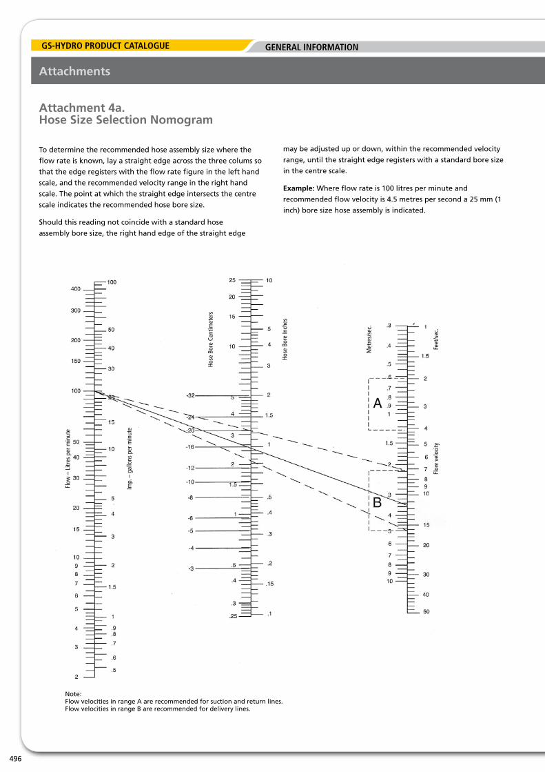
The pressure line is typically dimensioned so that the velocity does not exceed 5 m/s.
c) Return lines
The recommended return line velocity is 1...3 m/s. The return line is typically dimensioned so that the velocity does not exceed 3 m/s.
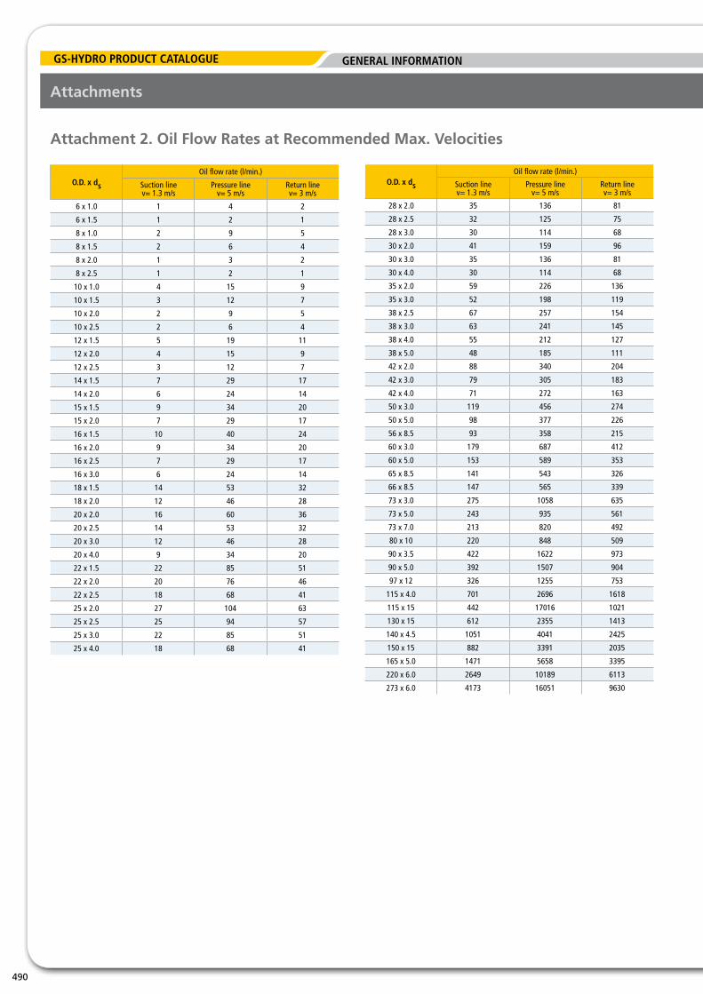
The oil flow rates at the recommended velocities are presented in attachment 2.
Fluid (oil) Velocities
GS-Hydro’s recommendation in regards to the oil velocities to be utilised for intial pipe sizing are as follows:
a) Suction lines
The suction line is typically dimensioned so that the velocity does not exceed 1.3 m/s.
b) Pressure lines
Introduction – Process Design
Hydraulic systems are designed for such a working pressure that
the required forces and torques are achieved. The machinery,
equipment and components of a hydraulic system are typically
designed so that a 15% increase in the working pressure is
possible. The components of the system have to be selected in
such a manner that the working parameters (pressure, flow rate
etc.) are not exceeded taking into account the possible increase
in the working pressure.
All design paramaters have to be selected specifically for each
case taking into account the customers requirements as well as
local rules, regulations and laws.
The pipes are dimensioned in such a manner that the pressure
loss in the system does not exceed the maximum allowable value
(pressure) at the maximum (or design) flow rate. The pressure
loss in a piping system is related to the square of the velocity of
the fluid ( p ~ v2). Therefore, the initial design is typically done
based on the velocity of the fluid. If required, the pressure loss in
the systems is then checked in order to verify that the maximum
acceptable pressure loss (and the maximum allowable working
pressure of the piping) is not exceeded.
The nomographic charts of pressure drops are shown in
attachment 1.
GS-
FLA
NG
ESY
STEM
CLA
MpS
VALV
ESA
dA
pTo
rSo
THEr
Co
Mpo
NEN
TSM
ACH
iNES
BiTE
TYp
E Fi
TTiN
GS
Ho
SES
&
Cou
pLiN
GS
SAE
J514
JiC
pi
pES
& T
uBE
SSW
iVEL
SQ
uiC
K
diS
CoN
NEC
TTE
ST
EQu
ipM
ENT
GENERAL INFORMATION
485
GEN
ErA
LiN
ForM
ATio
N
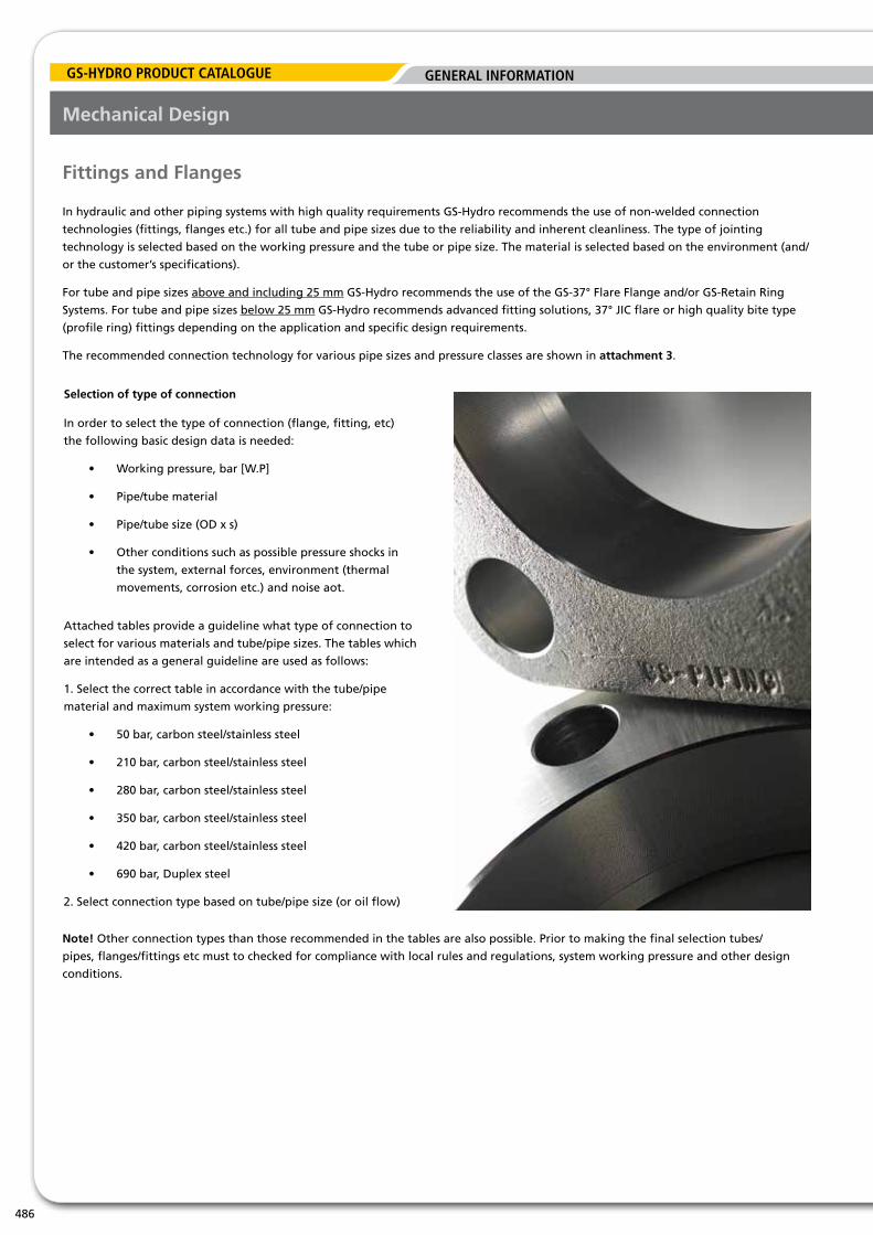
Mechanical Design
Introduction – Mechanical Design
When designing the piping system the following has to be taken
into account:
• pipe&tubematerial
• connectiontechnology:fittings,flanges,welding
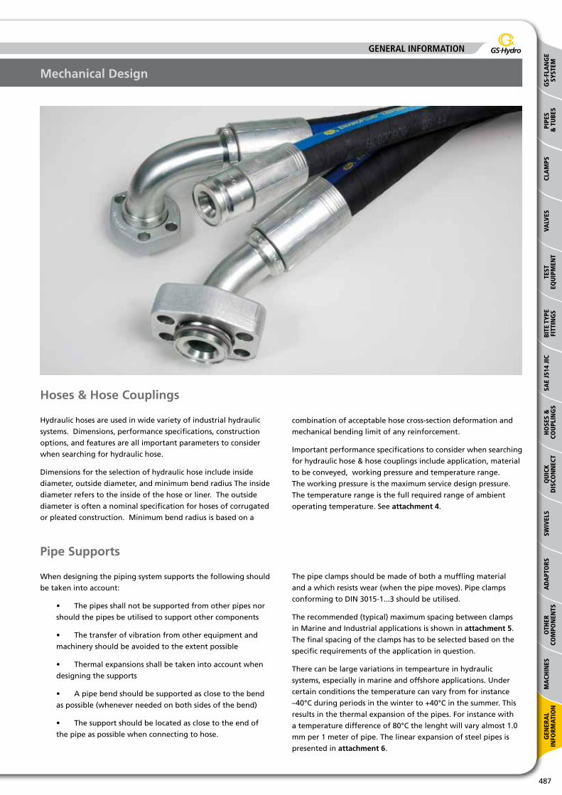
• hosesandhosecouplings
• pipesupports
Carbon Steel
Material Specification DIN 1630 –
Manufacturing Tolerances DIN 2391-1 EN 10305-4
Technical Terms of Delivery DIN 2391-2/C EN 10305-4
Stainless Steel (mm) Stainless Steel (sch)
Material Specification ASTM A269/A213 (A.W.) ASTM A312
Manufacturing Tolerances ASTM A269 ASTM A999
Pipe & Tube Materials
GS-Hydro recommends the use of cold-drawn, seamless precision
* = Vibration calculations are based on ships with max. propeller speed 2 rev/sec and max. number of propeller blades 6 (frequence 12 Hz)
Note! Detailed engineering performed by GS-Hydro is recommended in order to ensure proper clamp locations and spacing.
GS-Hydro’s engineering services can also include a FEM-analysis of the stresses in the piping system (the FEM analysis is
performed upon separate order).
Attachments
GENERAL INFORMATIONGS-HYDRO PRODUCT CATALOGUE
500
Attachment 6. Linear Expansion of Steel Pipes
100
80
63
50
40
31.5
25
20
16
12.5
10
8
6.3
5
4
3.15
2.5
2
1.6
1.25
1
160
100
63
40
27.5
16
10
6.3
4
2.5
1.6
1
0.63
0.4
0.25
0.16
0.1
125
100
80
63
50
40
31.5
25
20
16
12.5
10
8
Temperature difference, °C
Variation in lenght, mm
Pipe lenght, m
Attachments
GS-
FLA
NG
ESY
STEM
CLA
MpS
VALV
ESA
dA
pTo
rSo
THEr
Co
Mpo
NEN
TSM
ACH
iNES
BiTE
TYp
E Fi
TTiN
GS
Ho
SES
&
Cou
pLiN
GS
SAE
J514
JiC
pi
pES
& T
uBE
SSW
iVEL
SQ
uiC
K
diS
CoN
NEC
TTE
ST
EQu
ipM
ENT
GENERAL INFORMATION
501
GEN
ErA
LiN
ForM
ATio
N
Attachment 7. Thread identification
Attachments
Thread Identification JIC DIN
O.D. [mm] I.D. [mm] Type of thread Size Pitch Size Pitch
7.95 6.78 5/16”UNF
8.00 6.92 M8 04LL 1.0
9.73 8.57 1/8”BSP
10.00 8.92 M10 06LL 1.0
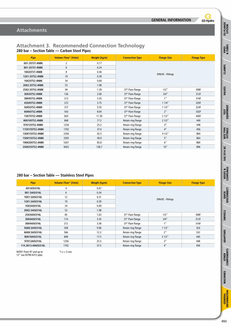
10.27 8.77 1/8”NPT
11.11 9.74 7/16”UNF -04 20
12.00 10.38 M12 08LL, 06L 1.0, 1.5
12.70 11.33 1/2”UNF -05 20
13.16 11.45 1/4”BSP
13.57 11.31 1/4”NPT
14.00 12.38 M14 08L, 06S 1.5
14.27 12.76 9/16”UNF -06 18
15.88 14.35 5/8”UNF
16.00 14.38 M16 10L, 08S 1.5
16.66 14.95 3/8”BSP
17.06 14.80 3/8”NPT
18.00 16.38 M18 12L, 10S 1.5
19.05 17.33 3/4”UNF -08 16
20.00 18.38 M20 12S 1.5
20.96 18.63 1/2”BSP
21.22 18.32 1/2”NPT
22.00 20.38 M22 15L, 14S 1.5
22.23 20.26 7/8”UNF -10 14
22.91 20.59 5/8”BSP
24.00 22.38 M24 16S 1.5
26.00 24.38 M26 18L 1.5
26.44 24.12 3/4”BSP
26.57 23.67 3/4”NPT
26.99 25.10 1 1/16”UN -12 12
27.00 24.83 M27 2.0
28.00 26.38 M28 2.0
30.00 27.83 M30 22L, 20S 2.0
30.16 28.20 1 3/16”UN
30.20 27.88 7/8”BSP
31.23 29.61 1”NPT
33.25 30.29 1”BSP
33.34 31.40 1 5/16”UN -16 12
36.00 33.83 M36 28L, 25S 2.0
41.28 39.30 1 5/8”UN -20 12
41.91 38.95 1 1/4”BSP
41.99 38.95 1 1/4”NPT
42.00 39.83 M42 30S 2.0
45.00 42.83 M45 35L 2.0
47.63 45.80 1 7/8”UN -24 12
47.80 44.85 1 1/2”BSP
48.05 44.52 1 1/2”NPT
52.00 49.83 M52 42L, 38S 2.0
59.60 56.66 2”BSP
60.09 56.56 2”NPT
63.50 60.80 2 1/2”UN
65.71 62.75 2 1/4”BSP
73.00 68.80 2 1/2”NPT
75.18 72.23 2 1/2”BSP
87.88 84.93 3”BSP
89.00 85.00 3”NPT
113.03 110.70 4”BSP
114.35 110.38 4”NPT
GENERAL INFORMATIONGS-HYDRO PRODUCT CATALOGUE
502
Cleanliness
Introduction – CleanlinessThe cleanliness of hydraulic piping systems is of utmost importance. Research shows that in average 80% of the operational problems of
hydraulic systems are related to impurities in the system. An important cause of the impurties are the welds in a welded piping system
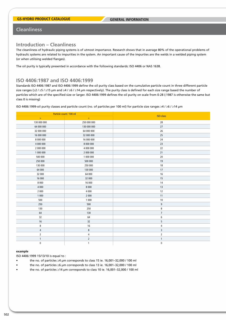
ISO 4406:1987 and ISO 4406:1999Standards ISO 4406:1987 and ISO 4406:1999 define the oil purity class based on the cumulative particle count in three different particle
size ranges (≥2 / ≥5 / ≥15 µm and ≥4 / ≥6 / ≥14 µm respectively). The purity class is defined for each size range based the number of
particles which are of the specified size or larger. ISO 4406:1999 defines the oil purity on scale from 0-28 (:1987 is otherwise the same but
class 0 is missing)
ISO 4406:1999-oil purity classes and particle count (no. of particles per 100 ml) for particle size ranges ≥4 / ≥6 / ≥14 µm


![Ch4[1]. General Piping Design](https://static.documents.pub/doc/80x56/577d35af1a28ab3a6b911c5a/ch41-general-piping-design.jpg)


