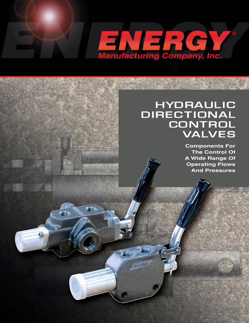
HYDRAULIC AULIC AULIC AULIC AULIC DIRECTIONAL DIRECTIONAL DIRECTIONAL DIRECTIONAL DIRECTIONAL CONTROL TROL TROL TROL TROL VALVES VES VES VES VES Components For The Control Of A Wide Range Of Operating Flows And Pressures ®
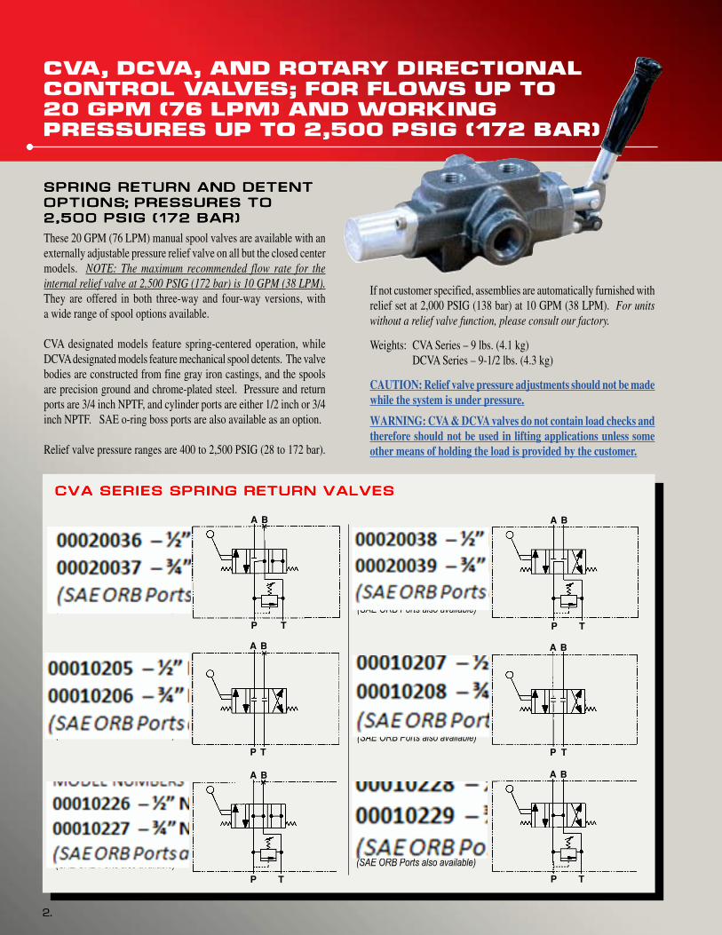
These 20 GPM (76 LPM) manual spool valves are available with anexternally adjustable pressure relief valve on all but the closed centermodels. NOTE: The maximum recommended flow rate for theinternal relief valve at 2,500 PSIG (172 bar) is 10 GPM (38 LPM).They are offered in both three-way and four-way versions, witha wide range of spool options available.
CVA designated models feature spring-centered operation, whileDCVA designated models feature mechanical spool detents. The valvebodies are constructed from fine gray iron castings, and the spoolsare precision ground and chrome-plated steel. Pressure and returnports are 3/4 inch NPTF, and cylinder ports are either 1/2 inch or 3/4inch NPTF. SAE o-ring boss ports are also available as an option.
Relief valve pressure ranges are 400 to 2,500 PSIG (28 to 172 bar).
Three-Way Tandem Center
with Relief Valve
MODEL NUMBERS
20036 – 1/2” NPTF Ports
20037 – 3/4” NPTF Ports
(SAE ORB Ports also available)
Three-Way Closed Center
No Relief Valve
MODEL NUMBERS
10205 – 1/2” NPTF Ports
10206 – 3/4” NPTF Ports
(SAE ORB Ports also available)
Three-Way Open Center
Spool with Relief Valve
MODEL NUMBERS
10226 – 1/2” NPTF Ports
10227 – 3/4” NPTF Ports
(SAE ORB Ports also available)
Four-Way Tandem Center
with Relief Valve
MODEL NUMBERS
20038 – 1/2” NPTF Ports
20039 – 3/4” NPTF Ports
(SAE ORB Ports also available)
Four-Way Closed Center
No Relief Valve
MODEL NUMBERS
10207 – 1/2” NPTF Ports
10208 – 3/4” NPTF Ports
(SAE ORB Ports also available)
Four-Way Open Center
Spool with Relief Valve
MODEL NUMBERS
10228 – 1/2” NPTF Ports
10229 – 3/4” NPTF Ports
(SAE ORB Ports also available)
CVA SERIES SPRING RETURN VALVESCVA SERIES SPRING RETURN VALVESCVA SERIES SPRING RETURN VALVESCVA SERIES SPRING RETURN VALVESCVA SERIES SPRING RETURN VALVES
A B
P T
A B
P T
A B
P T
A B
P T
A B
P T
A B
P T
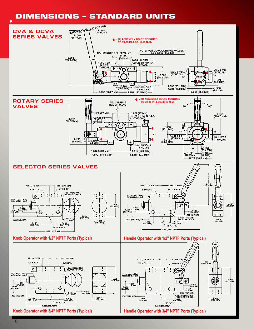
CVA, DCVA, AND ROTARY DIRECTIONAL
CONTROL VALVES; FOR FLOWS UP TO
20 GPM (76 LPM) AND WORKING
PRESSURES UP TO 2,500 PSIG (172 BAR)
If not customer specified, assemblies are automatically furnished withrelief set at 2,000 PSIG (138 bar) at 10 GPM (38 LPM). For unitswithout a relief valve function, please consult our factory.
Weights: CVA Series – 9 lbs. (4.1 kg)DCVA Series – 9-1/2 lbs. (4.3 kg)
CAUTION: Relief valve pressure adjustments should not be madewhile the system is under pressure.
WARNING: CVA & DCVA valves do not contain load checks andtherefore should not be used in lifting applications unless someother means of holding the load is provided by the customer.
ddunkel
Stamp
ddunkel
Stamp
ddunkel
Stamp
ddunkel
Stamp
ddunkel
Stamp
ddunkel
Rectangle
ddunkel
Rectangle
ddunkel
Rectangle
ddunkel
Rectangle
ddunkel
Rectangle
ddunkel
Rectangle
ddunkel
Rectangle
ddunkel
Stamp
ddunkel
Rectangle
ddunkel
Rectangle
CVA, DCVA, AND ROTARY DIRECTIONAL
CONTROL VALVES; FOR FLOWS UP TO
20 GPM (76 LPM) AND WORKING
PRESSURES UP TO 2,500 PSIG (172 BAR)
3.
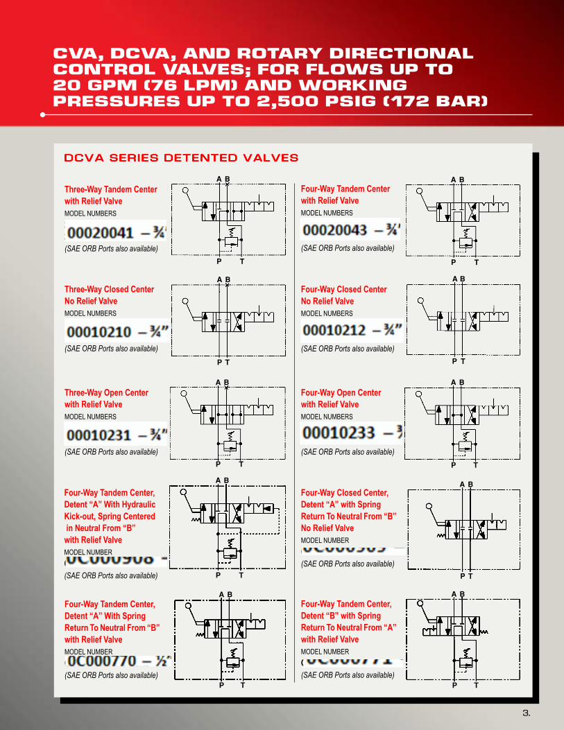
Three-Way Tandem Center
with Relief Valve
MODEL NUMBERS
20040 – 1/2” NPTF Ports
20041 – 3/4” NPTF Ports
(SAE ORB Ports also available)
Three-Way Closed Center
No Relief Valve
MODEL NUMBERS
10209 – 1/2” NPTF Ports
10210 – 3/4” NPTF Ports
(SAE ORB Ports also available)
Three-Way Open Center
with Relief Valve
MODEL NUMBERS
10230 – 1/2” NPTF Ports
10231 – 3/4” NPTF Ports
(SAE ORB Ports also available)
Four-Way Tandem Center
with Relief Valve
MODEL NUMBERS
20042 – 1/2” NPTF Ports
20043 – 3/4” NPTF Ports
(SAE ORB Ports also available)
Four-Way Closed Center
No Relief Valve
MODEL NUMBERS
10211 – 1/2” NPTF Ports
10212 – 3/4” NPTF Ports
(SAE ORB Ports also available)
Four-Way Open Center
with Relief Valve
MODEL NUMBERS
10232 – 1/2” NPTF Ports
10233 – 3/4” NPTF Ports
(SAE ORB Ports also available)
DCVA SERIES DETENTED VALVESDCVA SERIES DETENTED VALVESDCVA SERIES DETENTED VALVESDCVA SERIES DETENTED VALVESDCVA SERIES DETENTED VALVES
Four-Way Tandem Center,
Detent “A” With Hydraulic
Kick-out, Spring Centered
in Neutral From “B”
with Relief Valve
MODEL NUMBER
C-908 – 1/2” NPTF Ports
(SAE ORB Ports also available)
Four-Way Tandem Center,
Detent “A” With Spring
Return To Neutral From “B”
with Relief Valve
MODEL NUMBER
C-770 – 1/2” NPTF Ports
(SAE ORB Ports also available)
Four-Way Closed Center,
Detent “A” with Spring
Return To Neutral From “B”
No Relief Valve
MODEL NUMBER
C-909 – 1/2” NPTF Ports
(SAE ORB Ports also available)
Four-Way Tandem Center,
Detent “B” with Spring
Return To Neutral From “A”
with Relief Valve
MODEL NUMBER
C-771 – 1/2” NPTF Ports
(SAE ORB Ports also available)
A B
P T
A B
P T
A B
P T
A B
P T
A B
P T
A B
P T
A B
P T
A B
P T
A B
P T
A B
P T
ddunkel
Stamp
ddunkel
Stamp
ddunkel
Stamp
ddunkel
Stamp
ddunkel
Stamp
ddunkel
Stamp
ddunkel
Stamp
ddunkel
Stamp
ddunkel
Stamp
ddunkel
Stamp
ddunkel
Rectangle
ddunkel
Rectangle
ddunkel
Rectangle
ddunkel
Rectangle
ddunkel
Rectangle
ddunkel
Rectangle
ddunkel
Rectangle
ddunkel
Rectangle
4.
CVA, DCVA, AND ROTARY DIRECTIONAL
CONTROL VALVES; FOR FLOWS UP TO
20 GPM (76 LPM) AND WORKING
PRESSURES UP TO 2,500 PSIG (172 BAR)
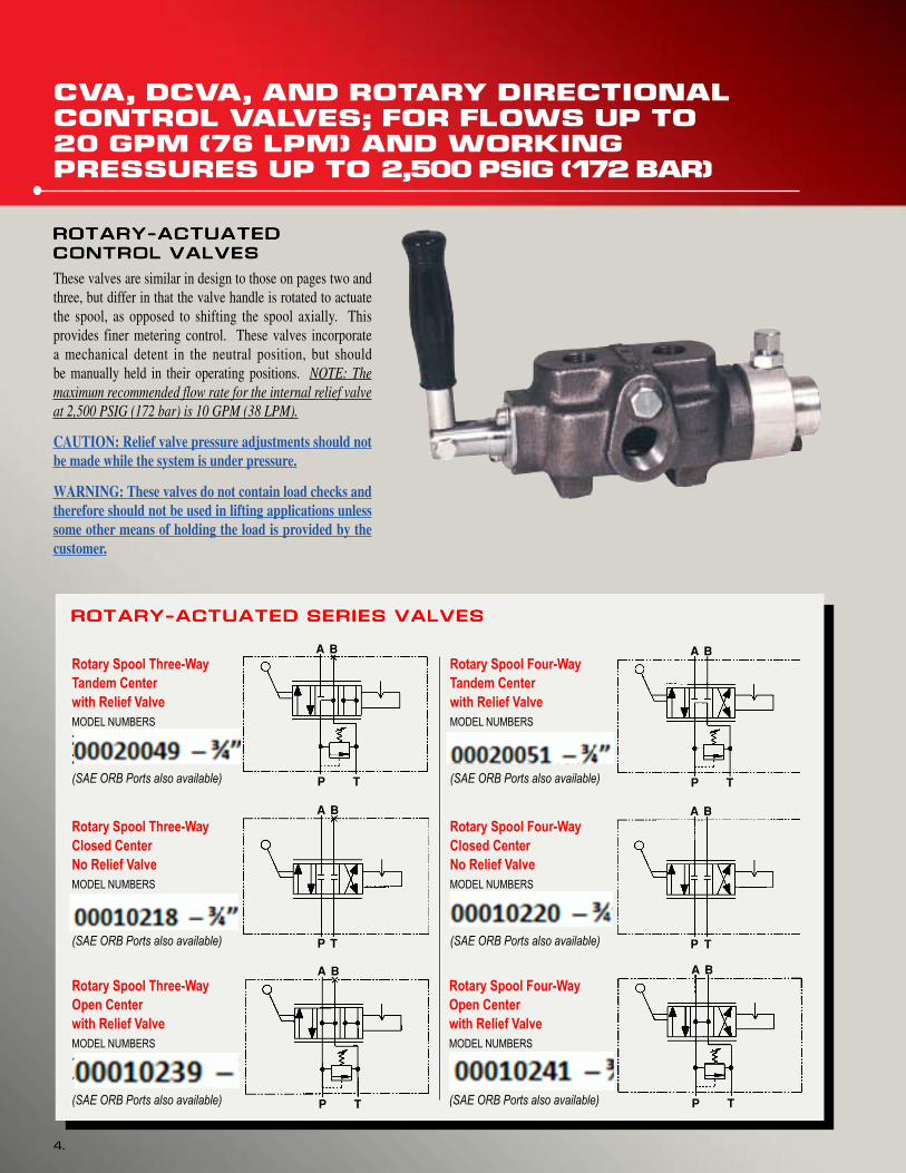
Rotary Spool Three-Way
Tandem Center
with Relief Valve
MODEL NUMBERS
20048 – 1/2” NPTF Ports
20049 – 3/4” NPTF Ports
(SAE ORB Ports also available)
Rotary Spool Three-Way
Closed Center
No Relief Valve
MODEL NUMBERS
10217 – 1/2” NPTF Ports
10218 – 3/4” NPTF Ports
(SAE ORB Ports also available)
Rotary Spool Three-Way
Open Center
with Relief Valve
MODEL NUMBERS
10238 – 1/2” NPTF Ports
10239 – 3/4” NPTF Ports
(SAE ORB Ports also available)
Rotary Spool Four-Way
Tandem Center
with Relief Valve
MODEL NUMBERS
20050 – 1/2” NPTF Ports
20051 – 3/4” NPTF Ports
(SAE ORB Ports also available)
Rotary Spool Four-Way
Closed Center
No Relief Valve
MODEL NUMBERS
10219 – 1/2” NPTF Ports
10220 – 3/4” NPTF Ports
(SAE ORB Ports also available)
Rotary Spool Four-Way
Open Center
with Relief Valve
MODEL NUMBERS
10240 – 1/2” NPTF Ports
10241 – 3/4” NPTF Ports
(SAE ORB Ports also available)
ROTARY-ACTUATED SERIES VALVESROTARY-ACTUATED SERIES VALVESROTARY-ACTUATED SERIES VALVESROTARY-ACTUATED SERIES VALVESROTARY-ACTUATED SERIES VALVES
CONTROL VALVESCONTROL VALVESCONTROL VALVESCONTROL VALVESCONTROL VALVES
These valves are similar in design to those on pages two andthree, but differ in that the valve handle is rotated to actuatethe spool, as opposed to shifting the spool axially. Thisprovides finer metering control. These valves incorporatea mechanical detent in the neutral position, but shouldbe manually held in their operating positions. NOTE: Themaximum recommended flow rate for the internal relief valveat 2,500 PSIG (172 bar) is 10 GPM (38 LPM).
CAUTION: Relief valve pressure adjustments should notbe made while the system is under pressure.
WARNING: These valves do not contain load checks andtherefore should not be used in lifting applications unlesssome other means of holding the load is provided by thecustomer.
ddunkel
Stamp
ddunkel
Stamp
ddunkel
Stamp
ddunkel
Stamp
ddunkel
Stamp
ddunkel
Stamp
ddunkel
Rectangle
ddunkel
Rectangle
ddunkel
Rectangle
ddunkel
Rectangle
ddunkel
Rectangle
ddunkel
Rectangle
ddunkel
Rectangle
5.
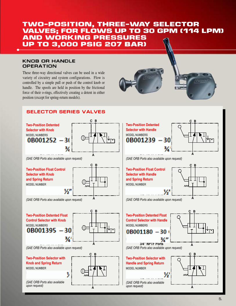
TWO-POSITION, THREE-WAY SELECTOR
VALVES; FOR FLOWS UP TO 30 GPM (114 LPM)
AND WORKING PRESSURES
UP TO 3,000 PSIG 207 BAR)
KNOB OR HANDLEKNOB OR HANDLEKNOB OR HANDLEKNOB OR HANDLEKNOB OR HANDLE
OPERATIONOPERATIONOPERATIONOPERATIONOPERATION
These three-way directional valves can be used in a widevariety of circuitry and system configurations. Flow iscontrolled by a simple pull or push of the control knob orhandle. The spools are held in position by the frictionalforce of their o-rings, effectively creating a detent in eitherposition (except for spring-return models).
Two-Position Detented
Selector with Knob
MODEL NUMBERS
B-1152 – 20 GPM (76 LPM)
1/2” NPTF Ports
B-1252 – 30 GPM (114 LPM)
3/4” NPTF Ports
(SAE ORB Ports also available upon request)
Two-Position Float Control
Selector with Knob
and Spring Return
MODEL NUMBER
B-1174 – 20 GPM (76 LPM)
1/2” NPTF Ports
(SAE ORB Ports also available upon request)
Two-Position Detented Float
Control Selector with Knob
MODEL NUMBERS
B-1138 – 20 GPM (76 LPM)
1/2” NPTF Ports
B-1395 – 30 GPM (114 LPM)
3/4” NPTF Ports
(SAE ORB Ports also available upon request)
Two-Position Selector with
Knob and Spring Return
MODEL NUMBER
B-1153 – 20 GPM (76 LPM)
1/2” NPTF Ports
(SAE ORB Ports also availableupon request)
Two-Position Detented
Selector with Handle
MODEL NUMBERS
B-1155 – 20 GPM (76 LPM)
1/2” NPTF Ports
B-1239 – 30 GPM (114 LPM)
3/4” NPTF Ports
(SAE ORB Ports also available upon request)
Two-Position Float Control
Selector with Handle
and Spring Return
MODEL NUMBER
B-1157 – 20 GPM (76 LPM)
1/2” NPTF Ports
(SAE ORB Ports also available upon request)
SELECTOR SERIES VALVESSELECTOR SERIES VALVESSELECTOR SERIES VALVESSELECTOR SERIES VALVESSELECTOR SERIES VALVES
CVA, DCVACVA, DCVACVA, DCVACVA, DCVACVA, DCVA,,,,, AND ROTARY SERIES VALVES AND ROTARY SERIES VALVES AND ROTARY SERIES VALVES AND ROTARY SERIES VALVES AND ROTARY SERIES VALVES
TYPICAL INTERNAL PRESSURE DROP; TYPICAL INTERNAL PRESSURE DROP; TYPICAL INTERNAL PRESSURE DROP; TYPICAL INTERNAL PRESSURE DROP; TYPICAL INTERNAL PRESSURE DROP; SELECTORSELECTORSELECTORSELECTORSELECTOR SERIES VALVES SERIES VALVES SERIES VALVES SERIES VALVES SERIES VALVES
NOTE: Measurements takenwith 164 SSU (35 cst).Hydraulic fluid at 100degrees F (38 degrees C).Values are the same forboth 1/2 inch NPTF and3/4 inch NPTF workports.
NOTE: Measurements takenwith 164 SSU (35 cst).Hydraulic fluid at 100degrees F (38 degrees C).Values are the same forboth 1/2 inch NPTF and3/4 inch NPTF workports.
WARNING: Pressure at “T” port in excess of 100 psig (7 bar) may interfere with the proper operation of some valve configurations.Please consult factory when using these valves in series, or when back pressure over 100 psig (7 bar) is present.
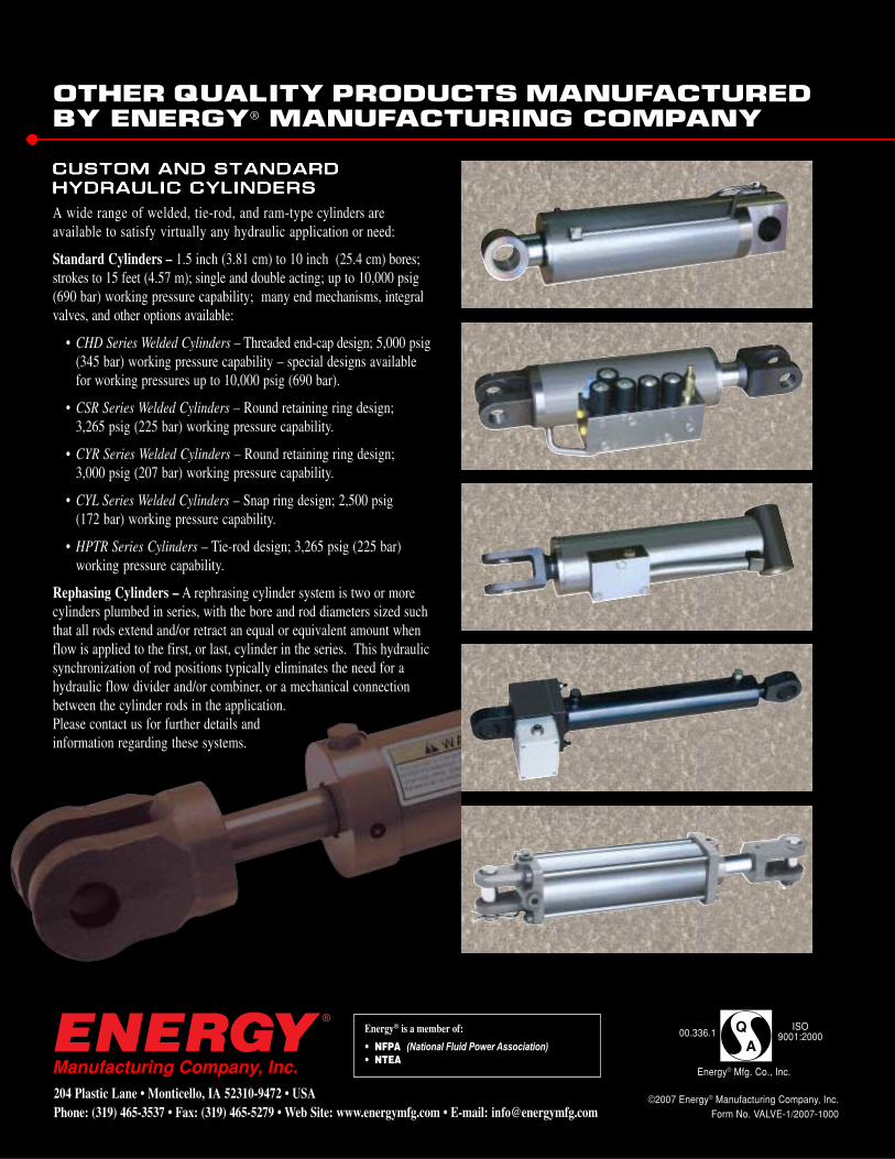
OTHER QUALITY PRODUCTS MANUFACTURED
BY ENERGY® MANUFACTURING COMPANY
CUSTOM AND STANDARDCUSTOM AND STANDARDCUSTOM AND STANDARDCUSTOM AND STANDARDCUSTOM AND STANDARD
A wide range of welded, tie-rod, and ram-type cylinders areavailable to satisfy virtually any hydraulic application or need:
Standard Cylinders – 1.5 inch (3.81 cm) to 10 inch (25.4 cm) bores;strokes to 15 feet (4.57 m); single and double acting; up to 10,000 psig(690 bar) working pressure capability; many end mechanisms, integralvalves, and other options available:
• CHD Series Welded Cylinders – Threaded end-cap design; 5,000 psig(345 bar) working pressure capability – special designs availablefor working pressures up to 10,000 psig (690 bar).
• CSR Series Welded Cylinders – Round retaining ring design;3,265 psig (225 bar) working pressure capability.
• CYR Series Welded Cylinders – Round retaining ring design;3,000 psig (207 bar) working pressure capability.
• CYL Series Welded Cylinders – Snap ring design; 2,500 psig(172 bar) working pressure capability.
Rephasing Cylinders – A rephrasing cylinder system is two or morecylinders plumbed in series, with the bore and rod diameters sized suchthat all rods extend and/or retract an equal or equivalent amount whenflow is applied to the first, or last, cylinder in the series. This hydraulicsynchronization of rod positions typically eliminates the need for ahydraulic flow divider and/or combiner, or a mechanical connectionbetween the cylinder rods in the application.Please contact us for further details andinformation regarding these systems.