CSM_Z_DS_E_3_1 1 General-purpose Basic Switch Z Best-selling Basic Switch Boasting High Precision and Wide Variety • A large switching capacity of 15 A with high repeat accuracy. • A wide range of variations in contact form for your selection: basic, split-contact, maintained-contact, and adjustable contact gap types. • A series of standard models for micro loads is available. • A series of molded terminal-type models incorporating safety terminal protective cover is available. Be sure to read Safety Precautions on page 22 and Safety Precautions for All Basic Switches. Model Number Structure Configuration • A variety of actuators is available for a wide range of application. • The contact mechanism of models for micro loads is a crossbar type with gold-alloy contacts, which ensures highly reliable operations for micro loads. • Contact Gap: H2: 0.20 mm (extra-high-sensitivity) H: 0.25 mm (high-sensitivity, micro voltage current load) G: 0.5 mm (standard) E: 1.8 mm (high-capacity) F: 1.0 mm (split-contact models) • These Switches use a rubber boot on the actuator and adhesive fill between the case and cover to increase resistance to drips. • Models with drip-proof terminal protective covers and molded terminals with resin filling are also available. • This type is identical in construction to the general-purpose basic switch except that it has two pairs of simultaneous acting contacts by splitting moving contacts. • Since the moving contacts are connected to a common terminal, either parallel or series connection is possible. • Highly reliable micro load switching is ensured if the model is used as a twin-contact switch. • The maintained-contact type has a reset button at the bottom of the switch case, in addition to the pushbutton (plunger) located on the opposite side of the reset button. Use these buttons alternately. • Since the Switch has greater pretravel than overtravel, it is suitable for use in reversible control circuits, manual reset circuits, safety limit circuits, and other circuits which are not preferable for automatic resetting. (For further details, refer to individual datasheets.) Basic models Split-contact models Maintained-contact models General-purpose Without terminal protective cover With terminal protective cover Molded terminal General-purpose Drip-proof General-purpose Refer to page 5. Refer to page 5. Refer to page 2. Refer to page 4. Refer to page 4. Refer to page 3. General-purpose Drip-proof Basic Models Split-contact Models Maintained-contact Models
Transcript
CSM_Z_DS_E_3_1
General-purpose Basic Switch
Z
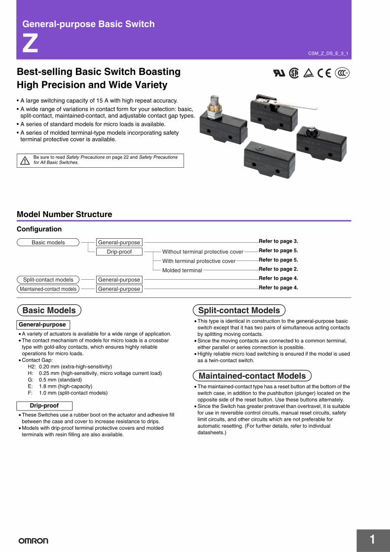
Best-selling Basic Switch Boasting High Precision and Wide Variety• A large switching capacity of 15 A with high repeat accuracy.
• A wide range of variations in contact form for your selection: basic, split-contact, maintained-contact, and adjustable contact gap types.
• A series of standard models for micro loads is available.
• A series of molded terminal-type models incorporating safety terminal protective cover is available.
Be sure to read Safety Precautions on page 22 and Safety Precautions for All Basic Switches.
Model Number Structure
Configuration
• A variety of actuators is available for a wide range of application.• The contact mechanism of models for micro loads is a crossbar
type with gold-alloy contacts, which ensures highly reliable operations for micro loads.
• Contact Gap:H2: 0.20 mm (extra-high-sensitivity)H: 0.25 mm (high-sensitivity, micro voltage current load)G: 0.5 mm (standard)E: 1.8 mm (high-capacity)F: 1.0 mm (split-contact models)
• These Switches use a rubber boot on the actuator and adhesive fill between the case and cover to increase resistance to drips.
• Models with drip-proof terminal protective covers and molded terminals with resin filling are also available.
• This type is identical in construction to the general-purpose basic switch except that it has two pairs of simultaneous acting contacts by splitting moving contacts.
• Since the moving contacts are connected to a common terminal, either parallel or series connection is possible.
• Highly reliable micro load switching is ensured if the model is used as a twin-contact switch.
• The maintained-contact type has a reset button at the bottom of the switch case, in addition to the pushbutton (plunger) located on the opposite side of the reset button. Use these buttons alternately.
• Since the Switch has greater pretravel than overtravel, it is suitable for use in reversible control circuits, manual reset circuits, safety limit circuits, and other circuits which are not preferable for automatic resetting. (For further details, refer to individual datasheets.)
Basic models
Split-contact models
Maintained-contact models
General-purpose
Without terminal protective cover
With terminal protective cover
Molded terminal
General-purpose
Drip-proof
General-purposeRefer to page 5.
Refer to page 5.
Refer to page 2.
Refer to page 4.
Refer to page 4.
Refer to page 3.
General-purpose
Drip-proof
Basic Models Split-contact Models
Maintained-contact Models
1
Z
Model Number LegendBasic Models
Z-@@@@-@(1)(2)(3)(4) (5)
(1) Ratings01 : 0.1 A (micro load)15 : 15 A
(2) Contact GapH2 : 0.20 (extra-high-sensitivity)H : 0.25 mm (high-sensitivity,
micro load)G : 0.5 mm (standard)E : 1.8 mm (high-capacity)
(3) ActuatorNone : Pin plungerS : Slim spring plungerD : Short spring plungerK : Spring plunger (medium OP)K3 : Spring plunger (high OP)Q3 : Panel mount plunger (medium
OP)Q : Panel mount plunger (medium
OP)Q8 : Panel mount plunger (high OP)Q22 : Panel mount roller plungerQ21 : Panel mount cross roller
plungerL : Leaf spring (high OF)L2 : Roller leaf springW21 : Short hinge leverW : Hinge lever (low OF)W3 : Hinge lever (medium OF)W32 : Hinge lever (high OF)W4 : Low-force hinge leverW44 : Long hinge leverW78 : Low-force wire hinge lever
(low OF)W52 : Low-force wire hinge lever
(high OF)W22 : Short hinge roller leverW2 : Hinge roller leverW25 : Hinge roller lever (large roller)W49 : Short hinge cross roller leverW54 : Hinge cross roller leverW2277 : Unidirectional short hinge
roller lever (low OF)M : Reverse hinge leverM22 : Reverse short hinge roller
leverM2 : Reverse hinge roller leverNJ : Flexible rod (high OF)NJS : Flexible rod (low OF)
(4) Degree of ProtectionNone : General-purpose55 : Drip-proof
(not include the terminals)A55 : Drip-proof
(including the terminals)(5) Terminals
None : Solder terminalB : Screw terminal
(with toothed washer)B5V : Screw terminal with terminal
cover (for Z-15G@A55 only)
Note: For combinations of models, Ordering Information on page 3 to 6.
Standard Models (Drip-proof Type/Molded Terminals)
Z-@55-M@@ @M(1) (2)(3) (4)
Split-contact Models
Z-10F@Y-B(1) (2)(3)(4) (5)
(1) Ratings10 : 10 A (split-contact models)
(2) Contact GapF : 1 mm (high-capacity)
(3) ActuatorNone : Pin plungerS : Slim spring plungerD : Short spring plungerQ : Panel mount plungerQ22 : Panel mount roller plungerW : Hinge leverW22 : Short hinge roller leverW2 : Hinge roller leverM22 : Reverse short hinge roller
lever(4) Construction
Y : Split-contact models(5) Terminals
B : Screw terminal (with toothed washer)
Maintained-contact Models
Z-15-E@R(1) (2)(3) (4)
(1) Ratings15 : 15 A
(2) Contact GapE : 1.8 mm (high capacity)
(3) ActuatorNone : Pin plungerS : Slim spring plungerW : Hinge lever
(4) StructureR : Maintained-contact models
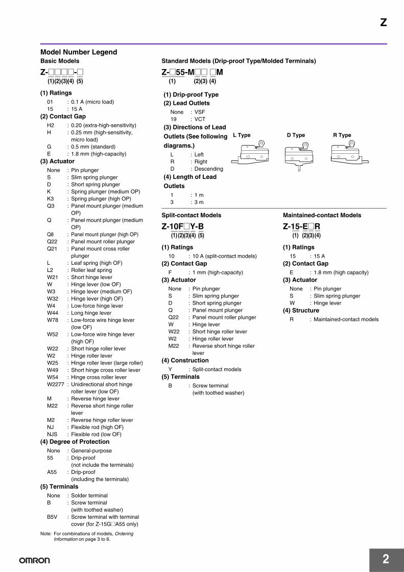
(1) Drip-proof Type(2) Lead Outlets
None : VSF19 : VCT
(3) Directions of Lead
Outlets (See following
diagrams.)L : LeftR : RightD : Descending
L Type D Type R Type
(4) Length of Lead
Outlets1 : 1 m3 : 3 m
2
Z
Ordering Information
Main UnitBasic Models (General-purpose)
*1. : Solder terminal : Screw terminal*2. The pin plungers of reverse-type models are continuously pressed by the actuator levers with compression coil springs and the pin plungers are freed by operating
the levers. Reverse-type models are highly vibration- and shock-resistive because the pin plungers are normally pressed.
ActuatorClassification Standard High-sensitivity Extra-high
sensitivity High-capacity Micro load
Contact gap G (0.5 mm) H (0.25 mm) H2 (0.20 mm) E (1.8 mm) H (0.25 mm)Terminal *1 Model Model Model Model Model
Pin plungerZ-15G Z-15H Z-15H2 Z-15E Z-01H
Z-15G-B Z-15H-B Z-15H2-B Z-15E-B Z-01H-B
Slim spring plungerZ-15GS Z-15HS
--- ---Z-01HS
Z-15GS-B Z-15HS-B Z-01HS-B
Short spring plunger
Z-15GD Z-15HD---
Z-15ED Z-01HD
Z-15GD-B Z-15HD-B Z-15ED-B Z-01HD-B
Panel mountplunger
Low OP
Z-15GQ3---
---
--- ---Z-15GQ3-B
Medium OP
Z-15GQ Z-15HQ Z-15EQ Z-01HQ
Z-15GQ-B Z-15HQ-B Z-15EQ-B Z-01HQ-B
High OP
Z-15GQ8--- --- ---
Z-15GQ8-B
Panel mount roller plunger
Z-15GQ22 Z-15HQ22---
Z-15EQ22---
Z-15GQ22-B Z-15HQ22-B Z-15EQ22-B
Panel mount cross roller plunger
Z-15GQ21 Z-15HQ21---
Z-15EQ21---
Z-15GQ21-B Z-15HQ21-B Z-15EQ21-B
Leaf springZ-15GL
--- --- --- ---Z-15GL-B
Roller leaf springZ-15GL2
--- --- --- ---Z-15GL2-B
Short hinge leverZ-15GW21
--- --- --- ---Z-15GW21-B
Hinge lever
Low OP
Z-15GW Z-15HW
--- --- ---
Z-15GW-B Z-15HW-B
Medium OP
Z-15GW3
---Z-15GW3-B
High OP
Z-15GW32
Z-15GW32-B
Low-force hinge lever
Z-15GW4 Z-15HW24--- --- ---
Z-15GW4-B Z-15HW24-B
Low- force wire hinge lever
Low OP
---
Z-15HW78
--- --- ---Z-15HW78-B
High OP
Z-15HW52
Z-15HW52-B
Short hinge roller lever
Z-15GW22 Z-15HW22---
Z-15EW22 Z-01HW22
Z-15GW22-B Z-15HW22-B Z-15EW22-B Z-01HW22-B
Short hinge cross roller lever
Z-15GW49--- --- --- ---
Z-15GW49-B
Hinge roller lever
Stan-dard
Z-15GW2 Z-15HW2
------ ---
Z-15GW2-B Z-15HW2-B
Large roller
Z-15GW25--- --- ---
Z-15GW25-B
Hinge cross roller lever
Z-15GW54--- --- --- ---
Z-15GW54-B
Unidirectional short hinge roller lever
ParallelZ-15GW2277
--- --- --- ---Z-15GW2277-B
Reverse hinge lever *2Z-15GM
--- --- --- ---Z-15GM-B
Reverse short hinge roller lever *2
Z-15GM22--- --- --- ---
Z-15GM22-B
Reverse hinge roller lever *2
Z-15GM2--- --- --- ---
Z-15GM2-B
Accessories (Terminal Covers, Actuators, and Separators): Refer to Z/A/X/DZ Common Accessories and Z/X/DZ Common Accessories.
3
Z
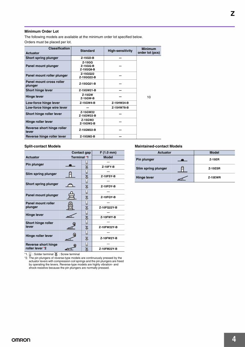
Minimum Order LotThe following models are available at the minimum order lot specified below.
Orders must be placed per lot.
Split-contact Models
*1. : Solder terminal : Screw terminal*2. The pin plungers of reverse-type models are continuously pressed by the
actuator levers with compression coil springs and the pin plungers are freed by operating the levers. Reverse-type models are highly vibration- and shock-resistive because the pin plungers are normally pressed.
Maintained-contact Models
ClassificationStandard High-sensitivity Minimum
order lot (pcs)ActuatorShort spring plunger Z-15GD-B ---
10
Panel mount plungerZ-15GQ
Z-15GQ-BZ-15GQ8-B
---
Panel mount roller plunger Z-15GQ22Z-15GQ22-B
---
Panel mount cross roller plunger Z-15GQ21-B ---
Short hinge lever Z-15GW21-B ---
Hinge lever Z-15GWZ-15GW-B
---
Low-force hinge lever Z-15GW4-B Z-15HW24-B
Low-force hinge wire lever --- Z-15HW78-B
Short hinge roller lever Z-15GW22Z-15GW22-B
---
Hinge roller lever Z-15GW2Z-15GW2-B
---
Reverse short hinge roller lever Z-15GM22-B ---
Reverse hinge roller lever Z-15GM2-B ---
Contact gap F (1.0 mm)Actuator Terminal *1 Model
Pin plunger---
Z-10FY-B
Slim spring plunger---
Z-10FSY-B
Short spring plunger---
Z-10FDY-B
Panel mount plunger---
Z-10FQY-B
Panel mount roller plunger
---
Z-10FQ22Y-B
Hinge lever---
Z-10FWY-B
Short hinge roller lever
---
Z-10FW22Y-B
Hinge roller lever---
Z-10FW2Y-B
Reverse short hinge roller lever *2
---
Z-10FM22Y-B
Actuator Model
Pin plunger Z-15ER
Slim spring plunger Z-15ESR
Hinge lever Z-15EWR
4
Z
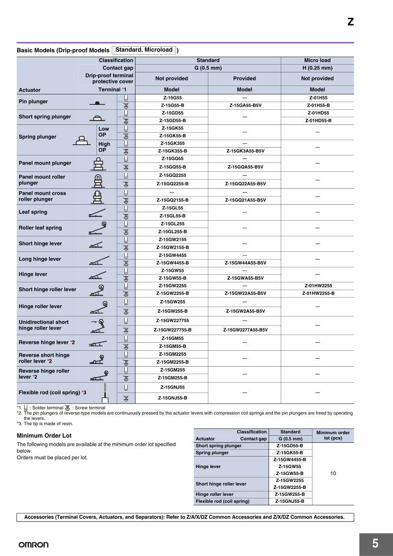
Basic Models (Drip-proof Models )
*1. : Solder terminal : Screw terminal*2. The pin plungers of reverse-type models are continuously pressed by the actuator levers with compression coil springs and the pin plungers are freed by operating
the levers.*3. The tip is made of resin.
Minimum Order LotThe following models are available at the minimum order lot specified below.Orders must be placed per lot.
Actuator
Classification Standard Micro loadContact gap G (0.5 mm) H (0.25 mm)
Drip-proof terminalprotective cover Not provided Provided Not provided
Terminal *1 Model Model Model
Pin plungerZ-15G55 --- Z-01H55
Z-15G55-B Z-15GA55-B5V Z-01H55-B
Short spring plungerZ-15GD55
---Z-01HD55
Z-15GD55-B Z-01HD55-B
Spring plunger
Low OP
Z-15GK55--- ---
Z-15GK55-B
High OP
Z-15GK355 ------
Z-15GK355-B Z-15GK3A55-B5V
Panel mount plungerZ-15GQ55 ---
---Z-15GQ55-B Z-15GQA55-B5V
Panel mount roller plunger
Z-15GQ2255 ------
Z-15GQ2255-B Z-15GQ22A55-B5V
Panel mount cross roller plunger
--- ------
Z-15GQ2155-B Z-15GQ21A55-B5V
Leaf springZ-15GL55
--- ---Z-15GL55-B
Roller leaf springZ-15GL255
--- ---Z-15GL255-B
Short hinge leverZ-15GW2155
--- ---Z-15GW2155-B
Long hinge leverZ-15GW4455 ---
---Z-15GW4455-B Z-15GW44A55-B5V
Hinge leverZ-15GW55 ---
---Z-15GW55-B Z-15GWA55-B5V
Short hinge roller leverZ-15GW2255 --- Z-01HW2255
Z-15GW2255-B Z-15GW22A55-B5V Z-01HW2255-B
Hinge roller leverZ-15GW255 ---
---Z-15GW255-B Z-15GW2A55-B5V
Unidirectional short hinge roller lever
Z-15GW227755 ------
Z-15GW227755-B Z-15GW2277A55-B5V
Reverse hinge lever *2Z-15GM55
--- ---Z-15GM55-B
Reverse short hinge roller lever *2
Z-15GM2255--- ---
Z-15GM2255-B
Reverse hinge roller lever *2
Z-15GM255--- ---
Z-15GM255-B
Flexible rod (coil spring) *3Z-15GNJ55
--- ---Z-15GNJ55-B
Standard, Microload
Classification Standard Minimum order lot (pcs)Actuator Contact gap G (0.5 mm)
Short spring plunger Z-15GD55-B
10
Spring plunger Z-15GK55-B
Hinge lever
Z-15GW4455-B
Z-15GW55
Z-15GW55-B
Short hinge roller leverZ-15GW2255
Z-15GW2255-B
Hinge roller lever Z-15GW255-B
Flexible rod (coil spring) Z-15GNJ55-B
Accessories (Terminal Covers, Actuators, and Separators): Refer to Z/A/X/DZ Common Accessories and Z/X/DZ Common Accessories.
5
Z
Basic Models (Drip-proof Models )
* : Solder terminal : Screw terminal
Minimum Order LotThe following models are available at the minimum order lot specified below.Orders must be placed per lot.
Specifications
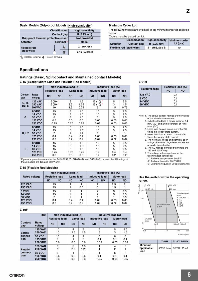
Ratings (Basic, Split-contact and Maintained contact Models)
Classification High-sensitivityContact gap H (0.25 mm)
Drip-proof terminal protective cover Not providedActuator Terminal * Model
Flexible rod(steel wire)
Z-15HNJS55
Z-15HNJS55-B
High-sensitivity
Classification High-sensitivity Minimum order lot (pcs)Actuator Contact gap H (0.25 mm)
Flexible rod (steel wire) Z-15HNJS55-B 10
Z-15 (Except Micro Load and Flexible Rod Models)
* Figures in parentheses are for the Z-15HW52, Z-15HW78(-B) and Z-15H2(-B) models, the AC ratings of these models are 125 and 250 V only.
Note: 1. The above current ratings are the values of the steady-state current.
2. Inductive load has a power factor of 0.4 min. (AC) and a time constant of 7 ms max. (DC).
3. Lamp load has an inrush current of 10 times the steady-state current.
4. Motor load has an inrush current of 6 times the steady-state current.
5. The normally closed and normally open ratings of reverse hinge lever models are opposite to each other.
6. The AC ratings of molded terminals are 125 and 250 V only.
7. The ratings values apply under the following test conditions:(1) Ambient temperature: 20±2°C(2) Ambient humidity: 65±5%RH(3) Operating frequency: 20 operations/min
Use the switch within the operating range.
Rated voltageResistive load (A)
NC NO125 VAC 0.18 VDC14 VDC30 VDC
0.10.10.1
Z-01H Z-15@, Z-10FY
Minimum applicable load
5 VDC 1 mA 5 VDC 160 mA
30
24
12
5
01 10 100 1,000
Current (mA)
0.1
1 mA
Standard loadareaZ-15H, H2Z-15GZ-15EZ-10FYZ-15ER
Micro load area Z-01H
26 mA0.16 mA
800 mW5 mW
100 mA 160 mA
Unusablerange
Vol
tage
(V
)
6
Z
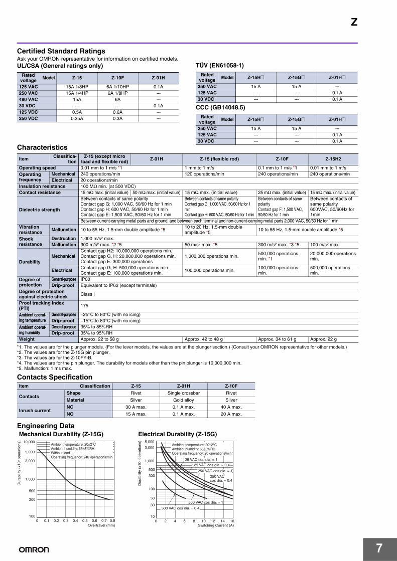
Certified Standard RatingsAsk your OMRON representative for information on certified models.UL/CSA (General ratings only) TÜV (EN61058-1)
CCC (GB14048.5)
Characteristics
*1. The values are for the plunger models. (For the lever models, the values are at the plunger section.) (Consult your OMRON representative for other models.)*2. The values are for the Z-15G pin plunger.*3. The values are for the Z-10FY-B.*4. The values are for the pin plunger. The durability for models other than the pin plunger is 10,000,000 min.*5. Malfunction: 1 ms max.
Between contacts of same polarityContact gap G: 1,000 VAC, 50/60 Hz for 1 minContact gap H: 600 VAC, 50/60 Hz for 1 minContact gap E: 1,500 VAC, 50/60 Hz for 1 min
Between contacts of same polarityContact gap G: 1,000 VAC, 50/60 Hz for 1 minContact gap H: 600 VAC, 50/60 Hz for 1 min
Between contacts of same polarityContact gap F: 1,500 VAC, 50/60 Hz for 1 min
Between contacts of same polarity600VAC, 50/60Hz for 1min
Between current-carrying metal parts and ground, and between each terminal and non-current-carrying metal parts 2,000 VAC, 50/60 Hz for 1 minVibration resistance Malfunction 10 to 55 Hz, 1.5-mm double amplitude *5 10 to 20 Hz, 1.5-mm double
amplitude *5 10 to 55 Hz, 1.5-mm double amplitude *5
Note: The Z-15GM is a reversible model and the NO and NC positions are reversed.
Molded Terminals
Note: The Z-15GM is a reversible model and the NO and NC positions are reversed.
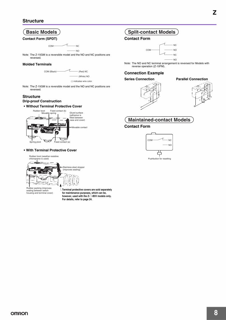
StructureDrip-proof Construction
• Without Terminal Protective Cover
• With Terminal Protective Cover
Contact Form
Note: The NO and NC terminal arrangement is reversed for Models with reverse operation (Z-10FM).
Connection Example
Contact Form
Basic Models
COM NC
NO
COM (Black) (Red) NC
(White) NO
( ) indicates wire color.
Rubber boot Fixed contact (b)Movable spring Glued surface
(adhesive isfilled betweencase and cover)
Movable contact
Fixed contact (a)Spring pivot
Rubber boot (weather-resistivechloroprene is used)
Stainless-steel stopper(improves sealing)
Rubber packing (improvessealing between switchhousing and terminal cover)
Terminal protective covers are sold separately for maintenance purposes, which can be, however, used with the Z-@-B5V models only.For details, refer to page 24.
Split-contact Models
NC
NOCOM
NC
NO
Series Connection Parallel Connection
Maintained-contact Models
Pushbutton for resetting
COM NC
NO
8
Z
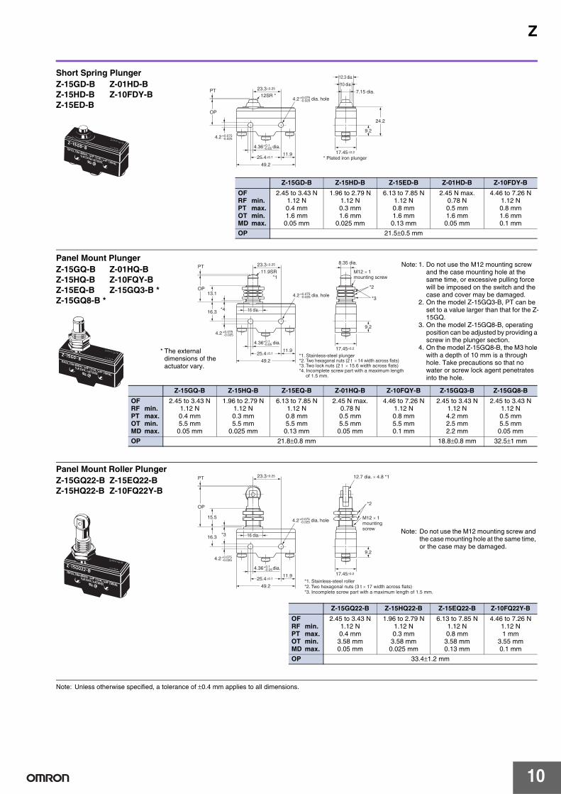
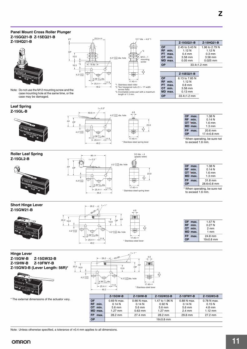
Dimensions (Unit: mm)
MountingUse M4 screws with plane washers and spring washers to mount the Switch. Tighten each mounting screw securely to a torque of 1.18 to 1.47 N·m.
When mounting the Switch to a panel, use a tightening torque of 2.94 to 4.9 N·m for the hexagonal nuts on the actuator.
Terminals
Dimensions and Operating CharacteristicsThe models, illustrations, and graphics are for screw-terminal models (-B). The “-A” at the end of the model number for solder terminal models has been omitted. For details of the terminals, see above.
Note: Unless otherwise specified, a tolerance of ±0.4 mm applies to all dimensions.
25.4±0.1
Two, 4.2 dia. mounting holes or M4 12.5 dia.+0.20
12.5 dia.+0.20
13+0.20
5+0.20
Panel Mount Roller PlungerPanel Mount Plunger
Basic Models Split-contact Models
Note: With reverse action models (Z-15GM), the positions of NO and NC terminals are reversed.
Basic Models and Split-contact ModelsGeneral-purpose
Operating Characteristics Model Z-15G-B Z-15H2-B Z-15H-B Z-15E-B Z-01H-B Z-10FY-B
Operating force OFRelease force RF min.Pretravel PT max.Overtravel OT min.Movement Differential MD max.
2.45 to 3.43 N1.12 N0.4 mm0.13 mm0.05 mm
1.96 to 2.5 N1.12 N0.3 mm
0.13 mm0.005 to 0.008 mm
1.96 to 2.75 N1.12 N0.3 mm0.13 mm0.025 mm
6.12 to 7.85 N1.12 N0.8 mm
0.13 mm0.13 mm
2.45 N max.0.78 N0.5 mm0.13 mm0.04 mm
4.46 to 7.26 N1.12 N0.8 mm0.13 mm0.1 mm
Operating Position OP 15.9±0.4 mm
49.2
11.925.4±0.1
23.3±0.25
24.2
17.45±0.2
OP
PT5.2 dia.
* Stainless-steel plunger (flat, 1R chamfered)
*4 dia.
9 dia.
9.2
4.36 dia.+0.1 -0.05
4.2+0.075-0.025
4.2 dia. hole+0.075 -0.025
Z-15GS-B Z-15HS-B Z-01HS Z-10FSY-B
OFRF min.PT max.OT min.MD max.
2.45 to 3.43 N1.12 N0.4 mm1.6 mm
0.05 mm
1.96 to 2.79 N1.12 N0.3 mm1.6 mm
0.025 mm
2.45 N max.0.78 N0.5 mm1.6 mm
0.05 mm
4.46 to 7.26 N1.12 N0.8 mm1.6 mm0.1 mm
OP 28.2±0.5 mm
Slim Spring PlungerZ-15GS-B Z-01HS-BZ-15HS-B Z-10FSY-B
9
Z
Note: Unless otherwise specified, a tolerance of ±0.4 mm applies to all dimensions.
49.2
11.925.4±0.1
23.3±0.25
24.2
17.45±0.2
OP
PT10 dia.
12.3 dia.
12SR *
* Plated iron plunger
7.15 dia.
9.2
4.36 dia.+0.1 -0.05
4.2+0.075-0.025
4.2 dia. hole+0.075 -0.025
Short Spring PlungerZ-15GD-B Z-01HD-BZ-15HD-B Z-10FDY-BZ-15ED-B
Z-15GD-B Z-15HD-B Z-15ED-B Z-01HD-B Z-10FDY-B
OFRF min.PT max.OT min.MD max.
2.45 to 3.43 N1.12 N0.4 mm1.6 mm
0.05 mm
1.96 to 2.79 N1.12 N0.3 mm1.6 mm
0.025 mm
6.13 to 7.85 N1.12 N0.8 mm1.6 mm
0.13 mm
2.45 N max.0.78 N0.5 mm1.6 mm
0.05 mm
4.46 to 7.26 N1.12 N0.8 mm1.6 mm0.1 mm
OP 21.5±0.5 mm
49.2
11.925.4±0.1
23.3±0.25
17.45±0.2
OP
PT8.35 dia.
11.9SR *1
*1. Stainless-steel plunger*2. Two hexagonal nuts (2 t × 14 width across flats)*3. Two lock nuts (2 t × 15.6 width across flats)*4. Incomplete screw part with a maximum length of 1.5 mm.
*416.3
13.1*2
*3
M12 × 1mounting screw
16 dia.
9.2
4.36 dia.+0.1 -0.05
4.2+0.075-0.025
4.2 dia. hole+0.075 -0.025
Panel Mount PlungerZ-15GQ-B Z-01HQ-BZ-15HQ-B Z-10FQY-BZ-15EQ-B Z-15GQ3-B *Z-15GQ8-B *
* The external dimensions of the actuator vary.
Note: 1. Do not use the M12 mounting screw and the case mounting hole at the same time, or excessive pulling force will be imposed on the switch and the case and cover may be damaged.
2. On the model Z-15GQ3-B, PT can be set to a value larger than that for the Z-15GQ.
3. On the model Z-15GQ8-B, operating position can be adjusted by providing a screw in the plunger section.
4. On the model Z-15GQ8-B, the M3 hole with a depth of 10 mm is a through hole. Take precautions so that no water or screw lock agent penetrates into the hole.
** The pin plungers of reverse-type models are continuously pressed by the actuator levers with compression coil springs and the pin plungers are freed by operating the levers. Reverse-type models are highly vibration- and shock-resistive because the pin plungers are normally pressed.
Note: Unless otherwise specified, a tolerance of ±0.4 mm applies to all dimensions.
49.2
11.925.4±0.1
26.2
OPFP
9.2
* Stainless-steel lever
t = 1 *
20.2 16.9 13.9
27.1
R
9.5 dia. × 4(plastic roller)
17.45±0.2
4.2+0.075-0.025 4.2 dia. hole+0.075
-0.025
4.36 dia.+0.1-0.05
Short Hinge Cross Roller LeverZ-15GW49-BZ-15GW54-B (Lever Length: 48.7R) *
Z-15GW49-B Z-15GW54-B
OF max.RF min.OT min.MD max.
1.67 N0.41 N2.4 mm
0.51 mm
0.98 N0.22 N4 mm1 mm
FP max.OP
33.3 mm31±0.4 mm
37.3 mm31±0.8 mm
* The external dimensions of the actuator vary.
17.45±0.2
4.2+0.075-0.025 4.2 dia. hole+0.075
-0.025
4.36 dia.+0.1-0.05
49.2
11.925.4±0.1
26.2
OPFP
* Stainless-steel lever
t = 1*
20.2 16.9 13.9
50R
20 dia. × 4(plastic roller)R2
9.2
Hinge Roller LeverZ-15GW25-B
OF max.RF min.OT min.MD max.
0.98 N0.21 N4 mm
1.6 mm
FP max.OP
47.5 mm41.2±0.8 mm
49.2
11.925.4±0.1
26.2
Operating direction
OP FP
* Stainless-steel lever
t = 1 *
20.2
34.1 max.
16.9 13.9
9.5 dia. × 4(plastic roller)
11.1R
31.9
R
9.2
17.45±0.2
4.2+0.075-0.025 4.2 dia. hole+0.075
-0.025
4.36 dia.+0.1-0.05
Unidirectional Short Hinge Roller LeverZ-15GW2277-B
OF max.RF min.OT min.MD max.
1.67 N0.41 N2.4 mm
0.51 mm
FP max.OP
43.6 mm41.3±0.8 mm
49.2
11.925.4±0.1
18.65 56R4.9
OP FP
* Stainless-steel lever
t = 1 *
20.2 17.4 13.9
9.2
17.45±0.2
4.2+0.075-0.025 4.2 dia. hole+0.075
-0.025
4.36 dia.+0.1-0.05
Reverse Hinge Lever **Z-15GM-B
OF max.RF min.OT min.MD max.
1.67 N0.27 N5.6 mm
0.89 mm
FP max.OP
23.8 mm19±0.8 mm
49.2
11.925.4±0.1
18.65
OP FP
* Stainless-steel lever
t = 1 *
20.2 17.4 13.9
18.5
R
9.5 dia. × 4(plastic roller)
9.2
17.45±0.2
4.2+0.075-0.025 4.2 dia. hole+0.075
-0.025
4.36 dia.+0.1-0.05
Reverse Short Hinge Roller Lever **Z-15GM22-BZ-10FM22Y-B
Z-15GM22-B Z-10FM22Y-B
OF max.RF min.OT min.MD max.
5.28 N1.67 N2 mm
0.28 mm
6.37 N1.67 N2 mm
0.56mm
FP max.OP
31.8 mm29.4±0.4 mm
33 mm29.4±0.4 mm
17.45±0.2
4.2+0.075-0.025 4.2 dia. hole+0.075
-0.025
4.36 dia.+0.1-0.05
49.2
11.925.4±0.1
18.65
OPFP
* Stainless-steel lever
t = 1*
20.2 17.4 13.9
9.5 dia. × 4(plastic roller)
40.6R
9.2
Reverse Hinge Roller Lever **Z-15GM2-B
OF max.RF min.OT min.MD max.
2.35 N0.55 N4 mm
0.64 mm
FP max.OP
35 mm30.2±0.8 mm
13
Z
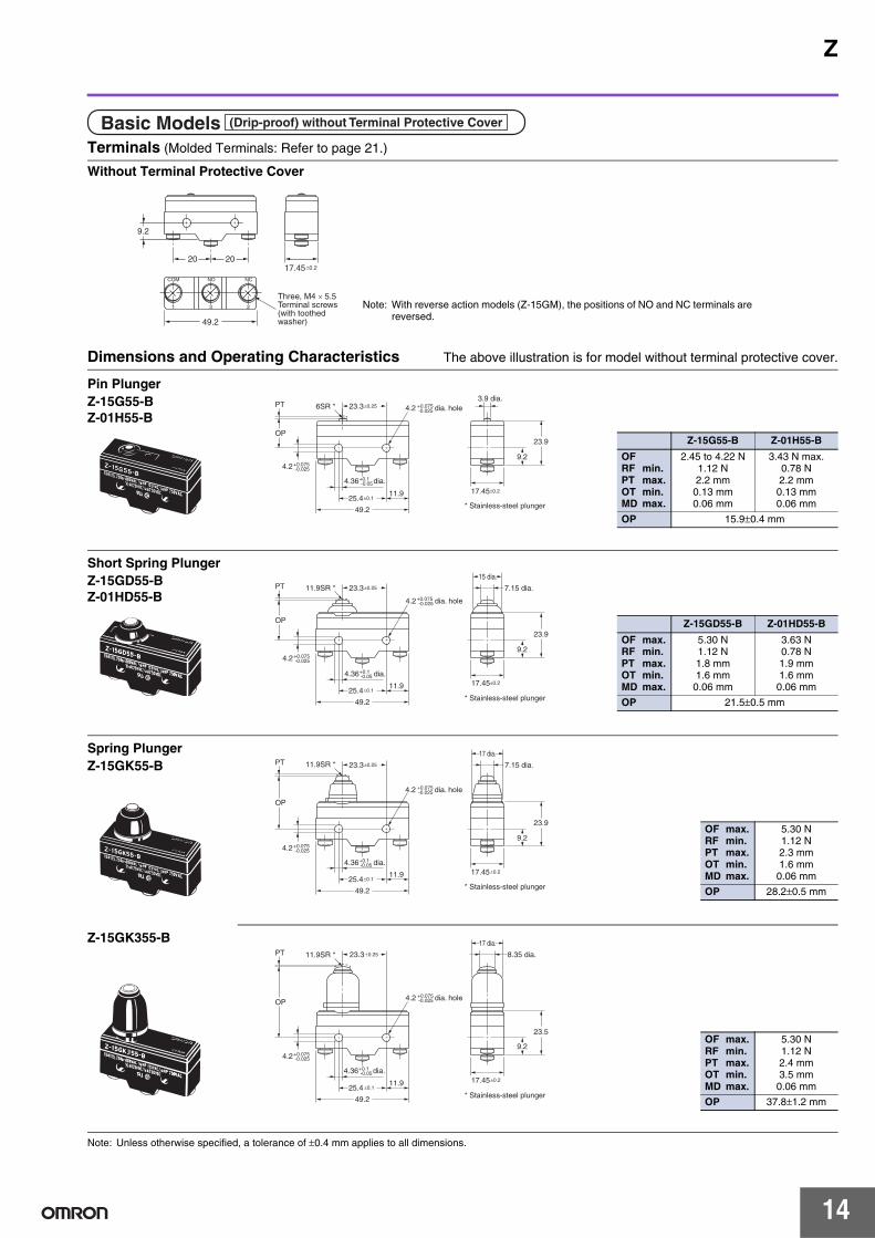
Terminals (Molded Terminals: Refer to page 21.)
Without Terminal Protective Cover
Dimensions and Operating Characteristics The above illustration is for model without terminal protective cover.
Note: Unless otherwise specified, a tolerance of ±0.4 mm applies to all dimensions.
Basic Models (Drip-proof) without Terminal Protective Cover
Note: With reverse action models (Z-15GM), the positions of NO and NC terminals are reversed.
17.45±0.2
4.2+0.075-0.025
4.2 dia. hole+0.075-0.025
4.36 dia.+0.1-0.05
49.2
11.925.4±0.1
23.3±0.25
23.9OP
PT3.9 dia.
6SR *
* Stainless-steel plunger
9.2
Pin PlungerZ-15G55-BZ-01H55-B
Z-15G55-B Z-01H55-B
OFRF min.PT max.OT min.MD max.
2.45 to 4.22 N1.12 N2.2 mm
0.13 mm0.06 mm
3.43 N max.0.78 N2.2 mm0.13 mm0.06 mm
OP 15.9±0.4 mm
49.2
11.925.4±0.1
23.3±0.25
23.9
OP
PT 7.15 dia.11.9SR *
* Stainless-steel plunger
15 dia.
9.2
17.45±0.2
4.2+0.075-0.025
4.2 dia. hole+0.075-0.025
4.36 dia.+0.1-0.05
Short Spring PlungerZ-15GD55-BZ-01HD55-B
Z-15GD55-B Z-01HD55-B
OF max.RF min.PT max.OT min.MD max.
5.30 N1.12 N1.8 mm1.6 mm
0.06 mm
3.63 N0.78 N1.9 mm1.6 mm0.06 mm
OP 21.5±0.5 mm
49.2
11.925.4±0.1
23.3±0.25
23.9
OP
PT 7.15 dia.11.9SR *
* Stainless-steel plunger
17 dia.
9.2
17.45±0.2
4.2+0.075-0.025
4.2 dia. hole+0.075-0.025
4.36 dia.+0.1-0.05
Spring PlungerZ-15GK55-B
OF max.RF min.PT max.OT min.MD max.
5.30 N1.12 N2.3 mm1.6 mm0.06 mm
OP 28.2±0.5 mm
49.2
11.925.4 ±0.1
23.3 ±0.25
23.5
OP
PT 8.35 dia.11.9SR *
* Stainless-steel plunger
17 dia.
9.2
17.45±0.2
4.2+0.075-0.025
4.2 dia. hole+0.075-0.025
4.36 dia.+0.1-0.05
Z-15GK355-B
OF max.RF min.PT max.OT min.MD max.
5.30 N1.12 N2.4 mm3.5 mm0.06 mm
OP 37.8±1.2 mm
14
Z
Note: Unless otherwise specified, a tolerance of ±0.4 mm applies to all dimensions.
49.2
11.925.4±0.1
23.3±0.25
OP
PT8.35 dia.
11.9SR *1
*1. Stainless-steel plunger*2. Two hexagonal nuts (2 t × 14 width across flats)*3. Two lock nuts (2 t × 15.6 width across flats)*4. Incomplete screw part with a maximum length of 1.5 mm.
*416.3
13.1*2
*3
M12 × 1Mountingscrew
9.2
17.45±0.2
4.2+0.075-0.025
4.2 dia. hole+0.075-0.025
4.36 dia.+0.1-0.05
16 dia.
Panel Mount PlungerZ-15GQ55-B
Note: Do not use the M12 mounting screw and the case mounting hole at the same time, or the case may be damaged.
OF max.RF min.PT max.OT min.MD max.
5.30 N1.12 N1.8 mm5.5 mm
0.06 mm
OP 21.8±0.8 mm
49.2
11.925.4±0.1
23.3±0.25
OP
PT
*1. Stainless-steel roller*2. Two hexagonal nuts (3 t × 17 width across flats)*3. Incomplete screw part with a maximum length of 1.5 mm.
*316.3
15.5
*2
12.7 dia. × 4.8 *1
M12 × 1mounting screw
9.2
17.45±0.2
4.2+0.075-0.025
4.2 dia. hole+0.075-0.025
4.36 dia.+0.1-0.05
16 dia.
Panel Mount Roller PlungerZ-15GQ2255-B
Note: Do not use the M12 mounting screw and the case mounting hole at the same time, or the case may be damaged.
OF max.RF min.PT max.OT min.MD max.
5.30 N1.12 N1.8 mm
3.58 mm0.06 mm
OP 33.4±1.2 mm
17.45±0.2
4.2+0.075-0.025
4.2 dia. hole+0.075-0.025
4.36 dia.+0.1-0.05
49.2
11.925.4 ±0.1
23.3±0.25
OP
PT
*1. Stainless-steel roller*2. Two hexagonal nuts (3 t × 17 width across flats)*3. Incomplete screw part with a maximum length of 1.5 mm.
*316.3
15.5
*2
12.7 dia. × 4.8 *1
16 dia.
M12 × 1mountingscrew
9.2
Panel Mount Cross Roller PlungerZ-15GQ2155-B
Note: Do not use the M12 mounting screw and the case mounting hole at the same time, or the case may be damaged.
OF max.RF min.PT max.OT min.MD max.
5.30 N1.12 N1.8 mm
3.58 mm0.06 mm
OP 33.4±1.2 mm
49.2
11.925.4±0.1
49.6±0.8
23.9OPFP
4.8
* Stainless-steel spring lever
t = 0.3 *
9.2
17.45±0.2
4.2+0.075-0.025
4.2 dia. hole+0.075-0.025
4.36 dia.+0.1-0.05
Leaf SpringZ-15GL55-B
* When operating, be sure not to exceed 1.6 mm.
OF max.RF min.OT *min.MD max.
1.96 N0.14 N1.6 mm1.3 mm
FP max.OP
20.6 mm17.5±0.8 mm
15
Z
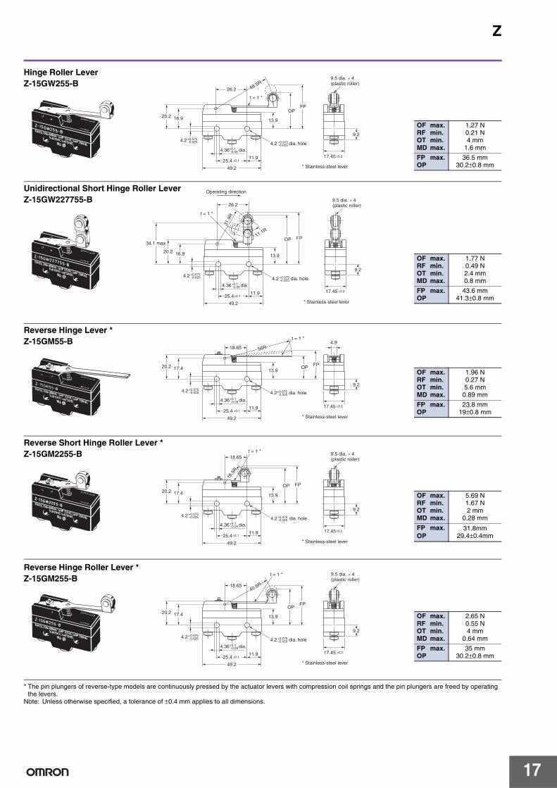
Note: Unless otherwise specified, a tolerance of ±0.4 mm applies to all dimensions.
* The pin plungers of reverse-type models are continuously pressed by the actuator levers with compression coil springs and the pin plungers are freed by operating the levers.
Note: Unless otherwise specified, a tolerance of ±0.4 mm applies to all dimensions.
49.2
11.925.4 ±0.1
26.2
OPFP
* Stainless-steel lever
t = 1 *
20.2 16.9 13.9
48.5R9.5 dia. × 4(plastic roller)
9.2
17.45±0.2
4.2+0.075-0.025 4.2 dia. hole+0.075
-0.025
4.36 dia.+0.1-0.05
Hinge Roller LeverZ-15GW255-B
OF max.RF min.OT min.MD max.
1.27 N0.21 N4 mm
1.6 mm
FP max.OP
36.5 mm30.2±0.8 mm
49.2
11.925.4±0.1
26.2
Operating direction
OP FP
* Stainless-steel lever
t = 1 *
20.2
34.1 max.
16.9 13.9
9.5 dia. × 4(plastic roller)
11.1R31
.9R
9.2
17.45 ±0.2
4.2+0.075-0.025 4.2 dia. hole+0.075
-0.025
4.36 dia.+0.1-0.05
Unidirectional Short Hinge Roller LeverZ-15GW227755-B
OF max.RF min.OT min.MD max.
1.77 N0.49 N2.4 mm0.8 mm
FP max.OP
43.6 mm41.3±0.8 mm
49.2
11.925.4 ±0.1
18.65 56R
17.45 ±0.2
4.9
OP FP
* Stainless-steel lever
t = 1 *
20.2 17.4 13.9
9.24.2+0.075
-0.025 4.2 dia. hole+0.075-0.025
4.36 dia.+0.1-0.05
Reverse Hinge Lever *Z-15GM55-B
OF max.RF min.OT min.MD max.
1.96 N0.27 N5.6 mm
0.89 mm
FP max.OP
23.8 mm19±0.8 mm
49.2
11.925.4±0.1
18.65
17.45±0.2
OP FP
* Stainless-steel lever
t = 1 *
20.2 17.4 13.9
18.5
R
9.5 dia. × 4(plastic roller)
9.24.2+0.075
-0.025 4.2 dia. hole+0.075-0.025
4.36 dia.+0.1-0.05
Reverse Short Hinge Roller Lever *Z-15GM2255-B
OF max.RF min.OT min.MD max.
5.69 N1.67 N2 mm
0.28 mm
FP max.OP
31.8mm29.4±0.4mm
17.45 ±0.2
9.5 dia. × 4(plastic roller)
49.2
11.925.4 ±0.1
18.65
OPFP
* Stainless-steel lever
t = 1 *
20.2 17.4 13.9
40.6R
9.24.2+0.075
-0.025 4.2 dia. hole+0.075-0.025
4.36 dia.+0.1-0.05
Reverse Hinge Roller Lever *Z-15GM255-B
OF max.RF min.OT min.MD max.
2.65 N0.55 N4 mm
0.64 mm
FP max.OP
35 mm30.2±0.8 mm
17
Z
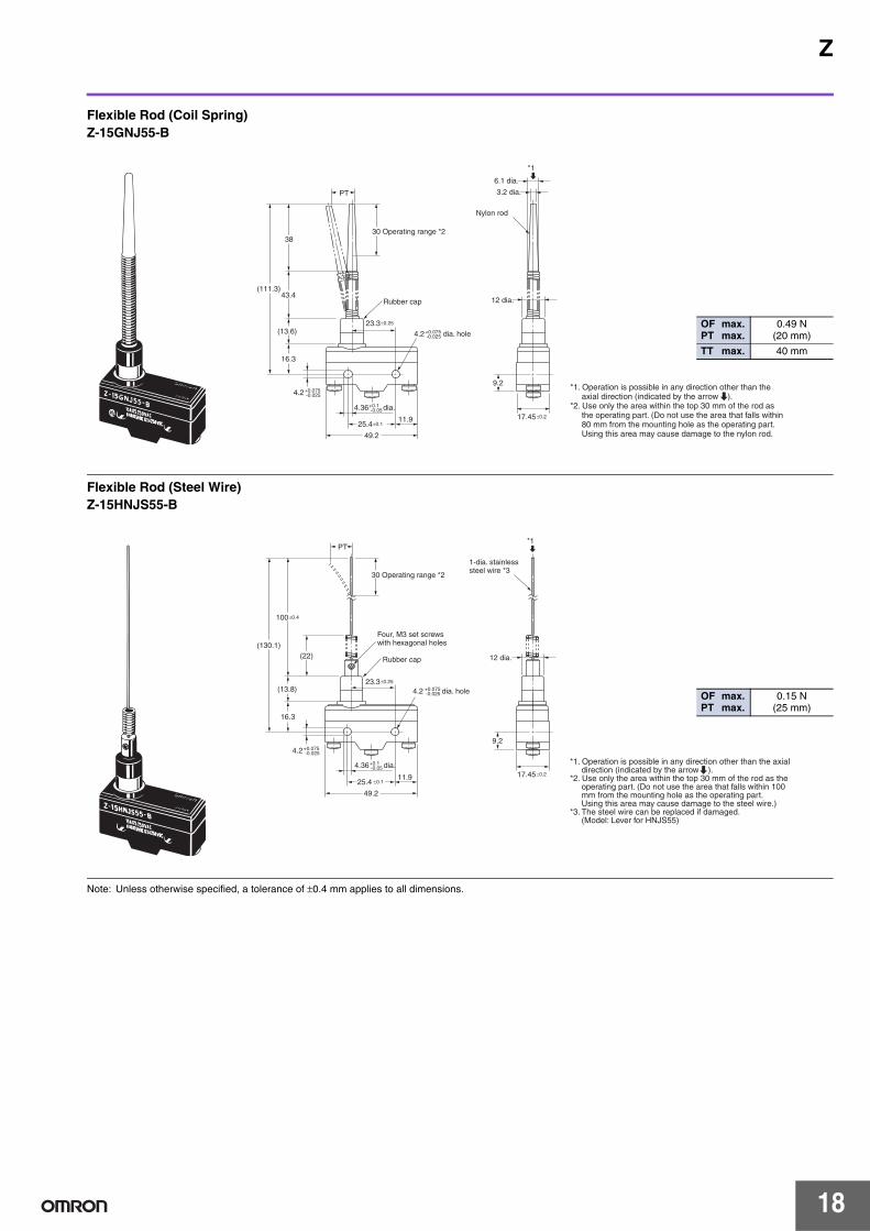
Note: Unless otherwise specified, a tolerance of ±0.4 mm applies to all dimensions.
17.45±0.2
12 dia.
49.2
11.925.4±0.1
23.3±0.25
PT
Rubber cap
30 Operating range *2
Nylon rod
3.2 dia.
6.1 dia.
38
43.4
(13.6)
16.3
(111.3)
*1
*1. Operation is possible in any direction other than the axial direction (indicated by the arrow ).*2. Use only the area within the top 30 mm of the rod as the operating part. (Do not use the area that falls within 80 mm from the mounting hole as the operating part. Using this area may cause damage to the nylon rod.
9.24.2+0.075
-0.025
4.2 dia. hole+0.075-0.025
4.36 dia.+0.1-0.05
Flexible Rod (Coil Spring)Z-15GNJ55-B
OF max.PT max.
0.49 N(20 mm)
TT max. 40 mm
49.2
11.925.4 ±0.1
23.3±0.25
17.45±0.2
PT
12 dia.Rubber cap
Four, M3 set screwswith hexagonal holes
30 Operating range *2
1-dia. stainlesssteel wire *3
100±0.4
(13.8)
(22)
16.3
(130.1)
*1
*1. Operation is possible in any direction other than the axial direction (indicated by the arrow ).*2. Use only the area within the top 30 mm of the rod as the operating part. (Do not use the area that falls within 100 mm from the mounting hole as the operating part. Using this area may cause damage to the steel wire.)*3. The steel wire can be replaced if damaged. (Model: Lever for HNJS55)
9.24.2+0.075
-0.025
4.36 dia.+0.1 -0.05
4.2 dia. hole+0.075-0.025
Flexible Rod (Steel Wire)Z-15HNJS55-B
OF max.PT max.
0.15 N(25 mm)
18
Z
Dimensions and Operating Characteristics
Note: Unless otherwise specified, a tolerance of ±0.4 mm applies to all dimensions.
Basic Models (Drip-proof) with Terminal Protective Cover
17.45 ±0.2
52.8
13.725.4 ±0.1
(11)
14.7
* Stainless-steel plunger
OP
(28.8)
PT 23.3 ±0.25 8.35 dia.11.9SR *
17 dia.
19.24.2+0.075
-0.025
4.2 dia. hole+0.075-0.025
4.36 dia.+0.1-0.05
Z-15GK3A55-B5V
OF max.RF min.PT max.OT min.MD max.
5.30 N1.12 N2.4 mm3.5 mm
0.06 mm
OP 37.8±1.2 mm
52.8
13.7
23.3±0.25
(11)
14.7
3.9 dia.
* Stainless-steel plunger
OP
6SR *
(28.8)
PT
19.2
17.45 ±0.2
4.2+0.075-0.025
4.2 dia. hole+0.075-0.025
4.36 dia.+0.1-0.05
25.4 ±0.1
Pin PlungerZ-15GA55-B5V
OF max.RF min.PT max.OT min.MD max.
2.45 to 4.22 N1.12 N2.2 mm
0.13 mm0.06 mm
OP 15.9±0.4 mm
16 dia.
17.45±0.2
52.8
13.725.4±0.1
(11)
OP
(28.8)
PT 23.3±0.25
8.35 dia.11.9SR *1
19.2
16.3
13.1
*1. Stainless-steel plunger*2. Two hexagonal nuts (2 t × 14 width across flat)*3. Two lock nuts (2 t × 15.6 width across flats)
*2
*3
M12 P = 1
4.2+0.075-0.025
4.2 dia. hole+0.075-0.025
4.36 dia.+0.1-0.05
Panel Mount PlungerZ-15GQA55-B5V
Note: Do not use the M12 mounting screw and the case mounting hole at the same time, or the case may be damaged.
OF max.RF min.PT max.OT min.MD max.
5.30 N1.12 N1.8 mm5.5 mm
0.06 mm
OP 21.8±0.8 mm
52.8
13.725.4 ±0.1
(11)
OP
(28.8)
PT 23.3±0.25
19.2
16.3
15.5
*1. Stainless-steel roller*2. Two hexagonal nuts (3 t × 17 width across flats)
16 dia.
*2
M12 P = 1
12.7 dia. × 4.8 *1
17.45±0.2
4.2+0.075-0.025
4.2 dia. hole+0.075-0.025
4.36 dia.+0.1-0.05
Panel Mount Roller PlungerZ-15GQ22A55-B5V
Note: Do not use the M12 mounting screw and the case mounting hole at the same time, or the case may be damaged.
OF max.RF min.PT max.OT min.MD max.
5.30 N1.12 N1.8 mm
3.58 mm0.06 mm
OP 33.4±1.2 mm
52.8
13.725.4 ±0.1
(11)
OP
(28.8)
PT 23.3 ±0.25
19.2
16.3
15.5
*1. Stainless-steel roller*2. Two hexagonal nuts (3 t × 17 width across flats)
16 dia.
*2
12.7 dia. × 4.8 *1
M12 P = 1
17.45 ±0.2
4.2+0.075-0.025
4.36 dia.+0.1 -0.05
4.2 dia. hole+0.075-0.025
Panel Mount Cross-roller PlungerZ-15GQ21A55-B5V
Note: Do not use the M12 mounting screw and the case mounting hole at the same time, or the case may be damaged.
OF max.RF min.PT max.OT min.MD max.
5.30 N1.12 N1.8 mm3.58mm0.06 mm
OP 33.4±1.2 mm
19
Z
Note: Unless otherwise specified, a tolerance of ±0.4 mm applies to all dimensions.
52.8
13.725.4±0.1
26.2
OPFP
(11)
4.9
* Stainless-steel lever
t = 1 *
20.2 16.9
19.2
13.9
100R
(28.8)
17.45±0.2
4.2+0.075-0.025
4.2 dia. hole+0.075-0.025
4.36 dia.+0.1 -0.05
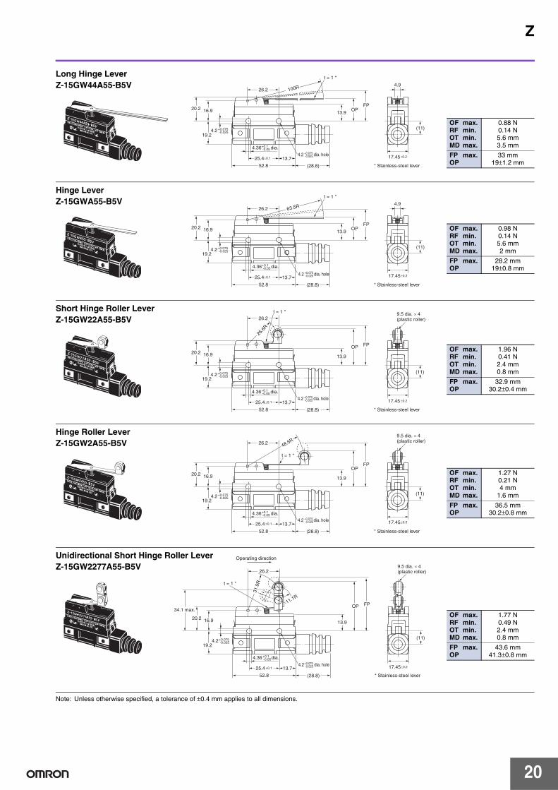
Long Hinge LeverZ-15GW44A55-B5V
OF max.RF min.OT min.MD max.
0.88 N0.14 N5.6 mm3.5 mm
FP max.OP
33 mm19±1.2 mm
52.8
13.7 25.4±0.1
26.2
OPFP
(11)
4.9
* Stainless-steel lever
t = 1 *
20.2 16.9
19.2
13.9
63.5R
(28.8)
17.45±0.2
4.2+0.075-0.025
4.2 dia. hole +0.075-0.025
4.36 dia.+0.1-0.05
Hinge LeverZ-15GWA55-B5V
OF max.RF min.OT min.MD max.
0.98 N0.14 N5.6 mm2 mm
FP max.OP
28.2 mm19±0.8 mm
52.8
13.725.4 ±0.1
26.2
17.45 ±0.2
OP FP
(11)
* Stainless-steel lever
t = 1 *
20.2 16.9
19.2
13.9
(28.8)
26.6
R
9.5 dia. × 4(plastic roller)
4.2+0.075-0.025
4.36 dia.+0.1 -0.05
4.2 dia. hole+0.075-0.025
Short Hinge Roller LeverZ-15GW22A55-B5V
OF max.RF min.OT min.MD max.
1.96 N0.41 N2.4 mm0.8 mm
FP max.OP
32.9 mm30.2±0.4 mm
52.8
13.725.4 ±0.1
26.2
17.45±0.2
OPFP
(11)
* Stainless-steel lever
20.2 16.9
19.2
13.9
(28.8)
9.5 dia. × 4(plastic roller)
t = 1 *
48.5R
4.2+0.075-0.025
4.36 dia.+0.1 -0.05
4.2 dia. hole+0.075-0.025
Hinge Roller LeverZ-15GW2A55-B5V
OF max.RF min.OT min.MD max.
1.27 N0.21 N4 mm
1.6 mm
FP max.OP
36.5 mm30.2±0.8 mm
52.8
13.725.4 ±0.1 17.45±0.2
OP FP
(11)
* Stainless-steel lever
20.2 16.9
19.2
13.9
(28.8)
9.5 dia. × 4(plastic roller)26.2
Operating direction
t = 1 *
11.1R
31.9
R
34.1 max.
4.2+0.075-0.025
4.2 dia. hole+0.075 -0.025
4.36 dia.+0.1 -0.05
Unidirectional Short Hinge Roller LeverZ-15GW2277A55-B5V
OF max.RF min.OT min.MD max.
1.77 N0.49 N2.4 mm0.8 mm
FP max.OP
43.6 mm41.3±0.8 mm
20
Z
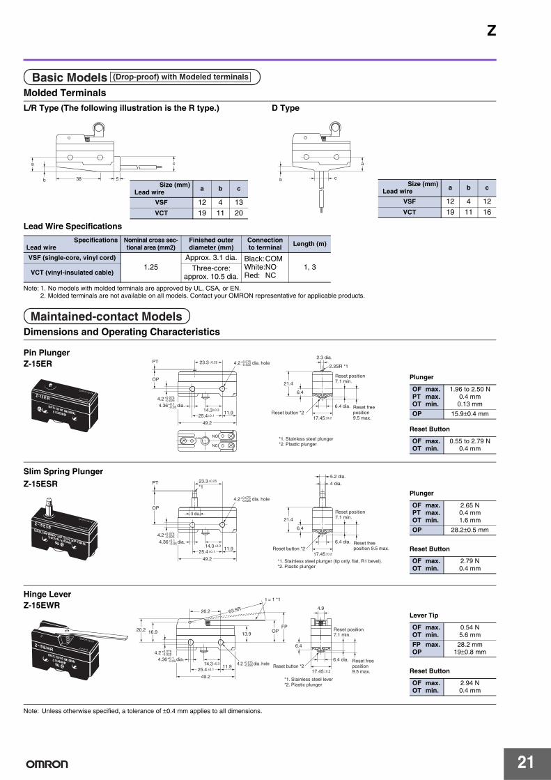
Molded Terminals
L/R Type (The following illustration is the R type.) D Type
Lead Wire Specifications
Note: 1. No models with molded terminals are approved by UL, CSA, or EN.2. Molded terminals are not available on all models. Contact your OMRON representative for applicable products.
Dimensions and Operating Characteristics
Note: Unless otherwise specified, a tolerance of ±0.4 mm applies to all dimensions.
Refer to Safety Precautions for All Basic Switches.
Terminal ConnectionWhen soldering lead wires to the Switch, make sure that the capacity of the soldering iron is 60 W maximum. Do not take more than 5 s to solder any part of the Switch. The characteristics of the Switch will deteriorate if a soldering iron with a capacity of more than 60 W is applied to any part of the Switch for 5 s or more.
Operation• Make sure that the switching frequency or speed is within the
specified range.1.If the switching speed is extremely slow, the contact may not be
switched smoothly, which may result in a contact failure or contact welding.
2.If the switching speed is extremely fast, switching shock may damage the Switch soon. If the switching frequency is too high, the contact may not catch up with the speed.
The rated permissible switching speed and frequency indicate the switching reliability of the Switch.The life of a Switch is determined at the specified switching speed. The life varies with the switching speed and frequency even when they are within the permissible ranges. In order to determine the life of a Switch model to be applied to a particular use, it is best to conduct an appropriate durability test on some samples of the model under actual conditions.
• Make sure that the actuator travel does not exceed the permissible OT position. The operating stroke must be set to 70% to 100% of the rated OT.
Mounting Location• Do not use the switch alone in atmospheres such as flammable or
explosive gases. Arcing and heat generation associated with switching may cause fires or explosions.
• Switches are generally not constructed with resistance against water. Use a protective cover to prevent direct spraying if the switch is used in locations subject to splashing or spurting oil or water, dust adhering.
• Install the switch in a location that is not directly subject to debris and dust from cutting. The actuator and the switch body must be protected from accumulated cutting debris and dirt.
• Do not use the switch in locations subject to hot water (greater than 60°C) or in water vapor.
• Do not use the switch outside the specified temperature and atmospheric conditions.The permissible ambient temperature depends on the model. (Refer to the specifications in this catalog.) Sudden thermal changes may cause thermal shock to distort the switch and result in faults.
• Mount a cover if the switch is to be installed in a location where worker inattention could result in incorrect operation or accidents.
• Subjecting the switch to continuous vibration or shock may result in contact failure or faulty operation due to abrasion powder and in reduced durability. Excessive vibration or shock will cause the contacts to operate malfunction or become damaged. Mount the switch in a location that is not subject to vibration or shock and in a direction that does not subject the switch to resonance.
• If silver contacts are used with relatively low frequency for a long time or are used with microloads, the sulfide coating produced on the contact surface will not be broken down and contact faults will result. Use a microload switch that uses gold contacts.
• Do not use the switch in atmospheres with high humidity or heat or in harmful gases, such as sulfide gas (H2S, SO2), ammonia gas (NH3), nitric acid gas (HNO3), or chlorine gas (Cl2). Doing so may impair functionality, such as with damage due to contacting faults or corrosion.
• The switch includes contacts. If the switch is used in an atmosphere with silicon gas, arc energy may cause silicon oxide (SiO2) to accumulate on the contacts and result in contact failure. If there is silicon oil, silicon filling, silicon wiring, or other silicon products in the vicinity of the switch, use a contact protection circuit to limit arcing and remove the source of the silicon gas.
MountingAlways make sure that the power is turned OFF before mounting, removing, or wiring the Switch, or performing maintenance.Electric shock or burning may occur.
Selecting ModelsWe recommend using Drip-proof Models (protection equivalent to IP62) in locations subject to floating dirt and dust. Other models do not have a protective structure.
WiringFor wiring, use a wire size that is appropriate for the applied voltage and the supplied current. When soldering the Switch, make sure that the capacity of the soldering iron is 60 W maximum. Do not take more than 5 s to solder any part of the Switch. Using the Switch with incomplete soldering may result in errors and heat, which may cause burning. The characteristics of the Switch will deteriorate if a soldering iron with a capacity of more than 60 W is used or if any part of the Switch is soldered for 6 s or longer.
Precautions for Safe Use
Precautions for Correct Use
Terminal box Terminal box
Incorrect Correct
Incorrect Correct
Incorrect Separate the installation lo-cation from heat sources.
Correct
Correct
(preventing malfunctions)
Incorrect
22
Z
TighteningThe suitable tightening torque for screw terminals is given below.
Screw terminals except for those on Split-contact Models (Z-10FY-B): 0.78 to 1.18 N·mScrew terminals on Split-contact Models (Z-10FY-B):0.49 to 1.18 N·m
Operation• Make sure that the switching speed and frequency are is within the
specified ranges.1. If the switching speed is extremely slow, the contacts may not be
switched smoothly, which may result in a contact failure or contact welding.
2. If the switching speed is extremely fast, switching shock may damage the Switch prematurely. If the switching frequency is too high, the contacts may not be able to keep up with the speed.The rated permissible switching speed and frequency indicate the switching reliability of the Switch.The life of a Switch is determined at the specified switching speed. The life varies with the switching speed and frequency even when they are within the permissible ranges. Always conduct appropriate durability tests under actual conditions before using a Switch.
• Make sure that the actuator travel does not exceed the permissible OT position. The operating stroke must be set to 70% to 100% of the rated OT.
Panel Mount Switch (Z-15@Q@, Z-01@Q@)• When mounting the panel mount plunger model with screws on a
side surface, be careful of the dog angle and operation speed. Excessive dog angle or operation speed may damage the Switch.
• When using the panel mount plunger model mounted with screws on a side surface, be careful not to apply a large shock. Applying a shock exceeding 1,000 m/s2 may damage the Switch.
• When using the panel mount plunger model mounted with screws on a side surface, remove the hexagonal nuts from the actuator.
High-sensitivity Switch (Z-15H)/
Extra-high-sensitivity Switch (Z-15H2)• When using the Switch in a DC circuit, be sure to provide an arc
suppressor as well because the small contact gap of the Switch may result in contact troubles.
• In an application where a high repeat accuracy is required, limit the current that flows through the Switch to within 0.1 A. Also, use a relay to control a high-capacity load if the Switch is connected to such a load. (In this case, the exciting current of the relay coil is the load of the Switch.)
• Do not apply a force of 19.6 N or higher to the pin plunger.• Exercise care that the environment conditions such as temperature
and humidity do not change abruptly.
Micro Load Applicable RangeUsing a model for ordinary loads to open or close the contact of a micro load circuit may result in faulty contact. Use models that operate in the following range. However, even when using micro load models within the operating range shown here, if inrush current occurs when the contact is opened or closed, it may increase contact wear and so decrease durability. Therefore, insert a contact protection circuit where necessary.The minimum applicable load is the N-level reference value. This value indicates the malfunction reference level for the reliability level of 60% (λ 60). The equation, λ 60 = 0.5×10⁻⁶/operations indicates that the estimated malfunction rate is less than 1/2,000,000 operations with a reliability level of 60%.
Models with Drip-proof Terminal Cover (Z-@A55-B5V)
Wiring• To attach the Protective Cover to the case, hold the cover in almost
parallel to the case and then push it to the case. If the cover is pushed diagonally, the rubber packing may slip off, degrading the sealability of the Switch.
• Use round solderless terminals having the following dimensions to connect leads to the terminals. Tighten the screws of terminals to a torque of 0.78 to 1.18 N·m. Use the terminal shown below.
• A cable 8.5 to 10.5 mm in diameter can be applicable to the sealing rubber of the lead outlet of the Switch. A two-core or three-core VCT cable having a cross-sectional area of 1.25 mm2 is especially suitable for this.
• Use M4 small screws with spring toothed washer are used as the terminal screws.
Z-01H Z-15@, Z-10FYMinimum applicableload 1 mA at 5 VDC 160 mA at 5 VDC
Drip-proof Switch (Z-@55)• The Switch is not perfectly oil-tight; so do not dip it in oil or water.• The rubber boots are made from weather-resistive chloroprene
rubber.• Do not use Basic Switches in places with radical changes in
temperature.• Rubber boots and rubber caps will tend to harden at lower ambient
temperatures. If an Actuator is used in a pressed state for an extended period of time at low temperatures, it may return slowly or it may not return at all. OMRON can provide special Actuators for use at low temperature with rubber boots or rubber caps made of silicon rubber, which has superior resistance to cold. Ask your OMRON representative for details.
Split-contact Switch (Z-10F@Y)The applicable current varies depending on how the contacts are used. If the Switch is connected in series, the Switch can endure a current 1.5 to 2 times higher than the current that can be applied in parallel connection.
Flexible Rod Switch (Z-15@NJ@55, Drip-proof)• When the rod is fully swung, the Switch may operate when the lever
returns, causing chattering. Use a circuit that compensates for chattering wherever possible.
• Do not switch the rod to the fullest extent when the Switch is to break a power circuit because such a practice may cause metal deposition to occur between the mating contacts of the Switch.
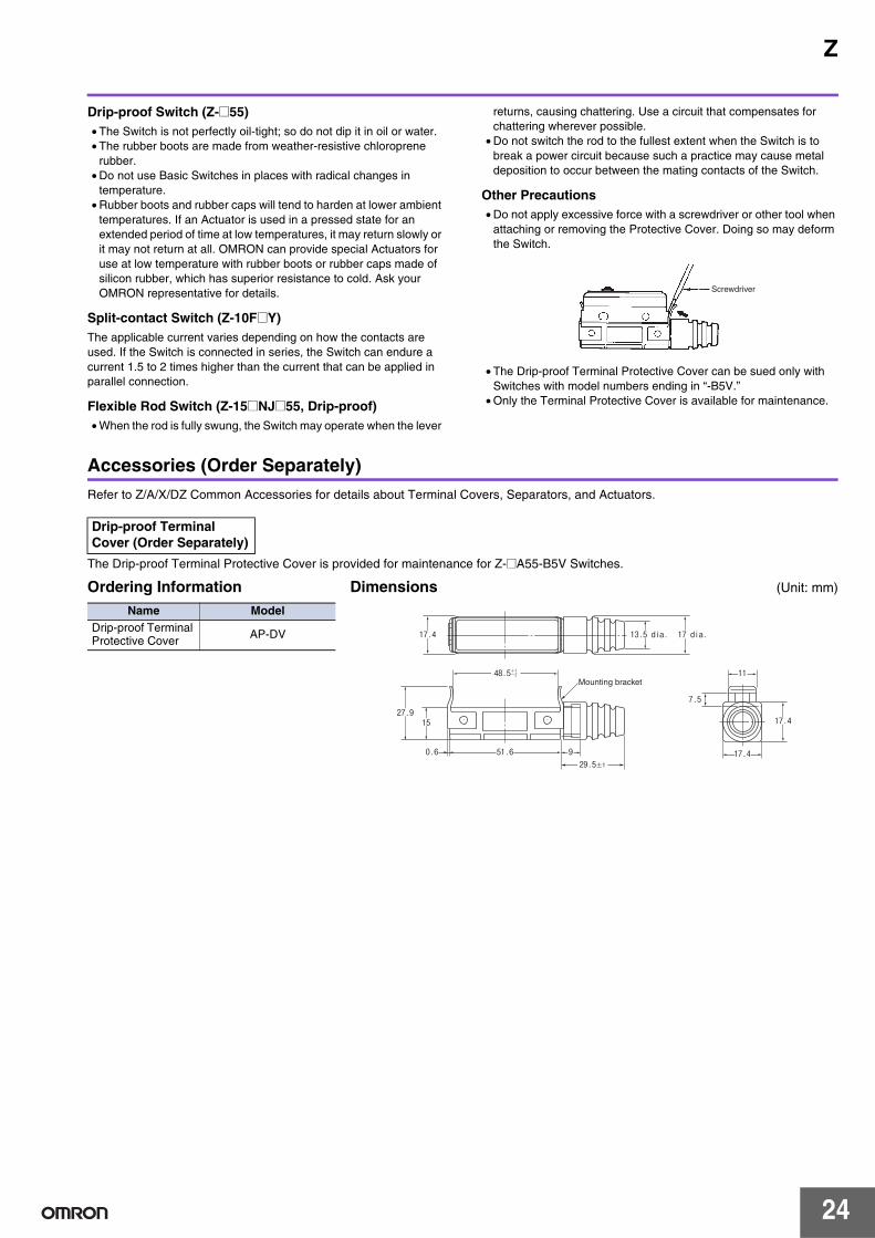
Other Precautions• Do not apply excessive force with a screwdriver or other tool when
attaching or removing the Protective Cover. Doing so may deform the Switch.
• The Drip-proof Terminal Protective Cover can be sued only with Switches with model numbers ending in “-B5V.”
• Only the Terminal Protective Cover is available for maintenance.
Accessories (Order Separately)Refer to Z/A/X/DZ Common Accessories for details about Terminal Covers, Separators, and Actuators.
The Drip-proof Terminal Protective Cover is provided for maintenance for Z-@A55-B5V Switches.
Screwdriver
Drip-proof Terminal Cover (Order Separately)
Ordering InformationName Model
Drip-proof Terminal Protective Cover AP-DV
Dimensions (Unit: mm)
48.5+1-2
51.60.6 929.5±1
15
7.5
11
17.4
17.4
27.9
Mounting bracket
17.4
17 dia.13.5 dia.
24
Read and Understand This Catalog Please read and understand this catalog before purchasing the products. Please consult your OMRON representative if you have any questions or comments.
Warranty and Limitations of Liability WARRANTY OMRON's exclusive warranty is that the products are free from defects in materials and workmanship for a period of one year (or other period if specified) from date of sale by OMRON. OMRON MAKES NO WARRANTY OR REPRESENTATION, EXPRESS OR IMPLIED, REGARDING NON-INFRINGEMENT, MERCHANTABILITY, OR FITNESS FOR PARTICULAR PURPOSE OF THE PRODUCTS. ANY BUYER OR USER ACKNOWLEDGES THAT THE BUYER OR USER ALONE HAS DETERMINED THAT THE PRODUCTS WILL SUITABLY MEET THE REQUIREMENTS OF THEIR INTENDED USE. OMRON DISCLAIMS ALL OTHER WARRANTIES, EXPRESS OR IMPLIED. LIMITATIONS OF LIABILITY OMRON SHALL NOT BE RESPONSIBLE FOR SPECIAL, INDIRECT, OR CONSEQUENTIAL DAMAGES, LOSS OF PROFITS OR COMMERCIAL LOSS IN ANY WAY CONNECTED WITH THE PRODUCTS, WHETHER SUCH CLAIM IS BASED ON CONTRACT, WARRANTY, NEGLIGENCE, OR STRICT LIABILITY. In no event shall the responsibility of OMRON for any act exceed the individual price of the product on which liability is asserted. IN NO EVENT SHALL OMRON BE RESPONSIBLE FOR WARRANTY, REPAIR, OR OTHER CLAIMS REGARDING THE PRODUCTS UNLESS OMRON'S ANALYSIS CONFIRMS THAT THE PRODUCTS WERE PROPERLY HANDLED, STORED, INSTALLED, AND MAINTAINED AND NOT SUBJECT TO CONTAMINATION, ABUSE, MISUSE, OR INAPPROPRIATE MODIFICATION OR REPAIR.
Application Considerations SUITABILITY FOR USE OMRON shall not be responsible for conformity with any standards, codes, or regulations that apply to the combination of products in the customer's application or use of the products. At the customer's request, OMRON will provide applicable third party certification documents identifying ratings and limitations of use that apply to the products. This information by itself is not sufficient for a complete determination of the suitability of the products in combination with the end product, machine, system, or other application or use. The following are some examples of applications for which particular attention must be given. This is not intended to be an exhaustive list of all possible uses of the products, nor is it intended to imply that the uses listed may be suitable for the products:
• Outdoor use, uses involving potential chemical contamination or electrical interference, or conditions or uses not described in this catalog. • Nuclear energy control systems, combustion systems, railroad systems, aviation systems, medical equipment, amusement machines, vehicles,
safety equipment, and installations subject to separate industry or government regulations. • Systems, machines, and equipment that could present a risk to life or property.
Please know and observe all prohibitions of use applicable to the products. NEVER USE THE PRODUCTS FOR AN APPLICATION INVOLVING SERIOUS RISK TO LIFE OR PROPERTY WITHOUT ENSURING THAT THE SYSTEM AS A WHOLE HAS BEEN DESIGNED TO ADDRESS THE RISKS, AND THAT THE OMRON PRODUCTS ARE PROPERLY RATED AND INSTALLED FOR THE INTENDED USE WITHIN THE OVERALL EQUIPMENT OR SYSTEM. PROGRAMMABLE PRODUCTS OMRON shall not be responsible for the user's programming of a programmable product, or any consequence thereof.
Disclaimers CHANGE IN SPECIFICATIONS Product specifications and accessories may be changed at any time based on improvements and other reasons. It is our practice to change model numbers when published ratings or features are changed, or when significant construction changes are made. However, some specifications of the products may be changed without any notice. When in doubt, special model numbers may be assigned to fix or establish key specifications for your application on your request. Please consult with your OMRON representative at any time to confirm actual specifications of purchased products. DIMENSIONS AND WEIGHTS Dimensions and weights are nominal and are not to be used for manufacturing purposes, even when tolerances are shown. PERFORMANCE DATA Performance data given in this catalog is provided as a guide for the user in determining suitability and does not constitute a warranty. It may represent the result of OMRON’s test conditions, and the users must correlate it to actual application requirements. Actual performance is subject to the OMRON Warranty and Limitations of Liability. ERRORS AND OMISSIONS The information in this document has been carefully checked and is believed to be accurate; however, no responsibility is assumed for clerical, typographical, or proofreading errors, or omissions.
2009.12
In the interest of product improvement, specifications are subject to change without notice.
OMRON Corporation Industrial Automation Company http://www.ia.omron.com/
(c)Copyright OMRON Corporation 2009 All Right Reserved.


![o u ^ W } µ Z } ] Ç Z µ ( } Y µ o ] ( ] ] } v Z&Y · W ^W ... · Automotive RO/RO Terminal. Ancillary Buildings Design-Build Package. Project Information Meeting. January 22,](https://static.documents.pub/doc/80x56/5f90e18a0dc106356c18b837/o-u-w-z-z-y-o-v-zy-w-w-automotive-roro.jpg)


![Main Terminal/Concourse Z Tenant Design Standards€¦ · IAD Vol. 2 - Main Terminal/Concourse Z Tenant Design Standards [THIS DOCUMENT] ... 5.2 General Criteria/Prohibitions.....](https://static.documents.pub/doc/80x56/5ead68e38af11c63ff5302d0/main-terminalconcourse-z-tenant-design-standards-iad-vol-2-main-terminalconcourse.jpg)


