Emanuele Stomeo, Student Member, IEEE, Tatiana Kalganova, and Cyrille Lambert
Abstract—Evolvable hardware (EHW) refers to self-reconfiguration hardware design, where the configuration isunder the control of an evolutionary algorithm (EA). One ofthe main difficulties in using EHW to solve real-world problemsis scalability, which limits the size of the circuit that may beevolved. This paper outlines a new type of decomposition strategyfor EHW, the “generalized disjunction decomposition” (GDD),which allows the evolution of large circuits. The proposed methodhas been extensively tested, not only with multipliers and paritybit problems traditionally used in the EHW community, butalso with logic circuits taken from the Microelectronics Centerof North Carolina (MCNC) benchmark library and randomlygenerated circuits. In order to achieve statistically relevantresults, each analyzed logic circuit has been evolved 100 times,and the average of these results is presented and compared withother EHW techniques. This approach is necessary because ofthe probabilistic nature of EA; the same logic circuit may notbe solved in the same way if tested several times. The proposedmethod has been examined in an extrinsic EHW system using the(1 + λ) evolution strategy. The results obtained demonstrate thatGDD significantly improves the evolution of logic circuits in termsof the number of generations, reduces computational time as it isable to reduce the required time for a single iteration of the EA,and enables the evolution of larger circuits never before evolved.In addition to the proposed method, a short overview of EHWsystems together with the most recent applications in electricalcircuit design is provided.
Index Terms—Adaptive system, evolutionary computation,evolvable hardware (EHW), problem decomposition.
I. INTRODUCTION
EVOLVABLE hardware (EHW) [1]–[12], also known asevolutionary electronics and hardware evolution, is a tech-
nique to automatically design circuits (digital [5], [9], [13] andanalog [5]–[7], [14], [15], antennas [16]–[18], and robots [1],[19], [20]) using methods inspired by natural evolution. Thecircuit configuration is carried out under the control of evolu-tionary algorithms (EAs) [21]–[25]. These techniques began tobe treated with increasing interest in the 1960s when Hollandintroduced the concept of genetic algorithms (GAs) [26], [27],which are the most general methods of solving search andoptimization problems. Research in this area has introducedother EAs, such as genetic programming (GP) [28]–[30], evo-lution strategy (ES) [24], grammatical evolution (GE) [31],
Manuscript received May 4, 2005; revised July 25, 2005 and December 27,2005. This work was supported in part by the Engineering and Physical Sci-ences Research Council under Grant GR/S17178. This paper was recommendedby Associate Editor H. Takagi.
The authors are with the School of Engineering and Design, BrunelUniversity, UB8 3PH Middlesex, U.K. (e-mail: [email protected]; [email protected]).
Digital Object Identifier 10.1109/TSMCB.2006.872259
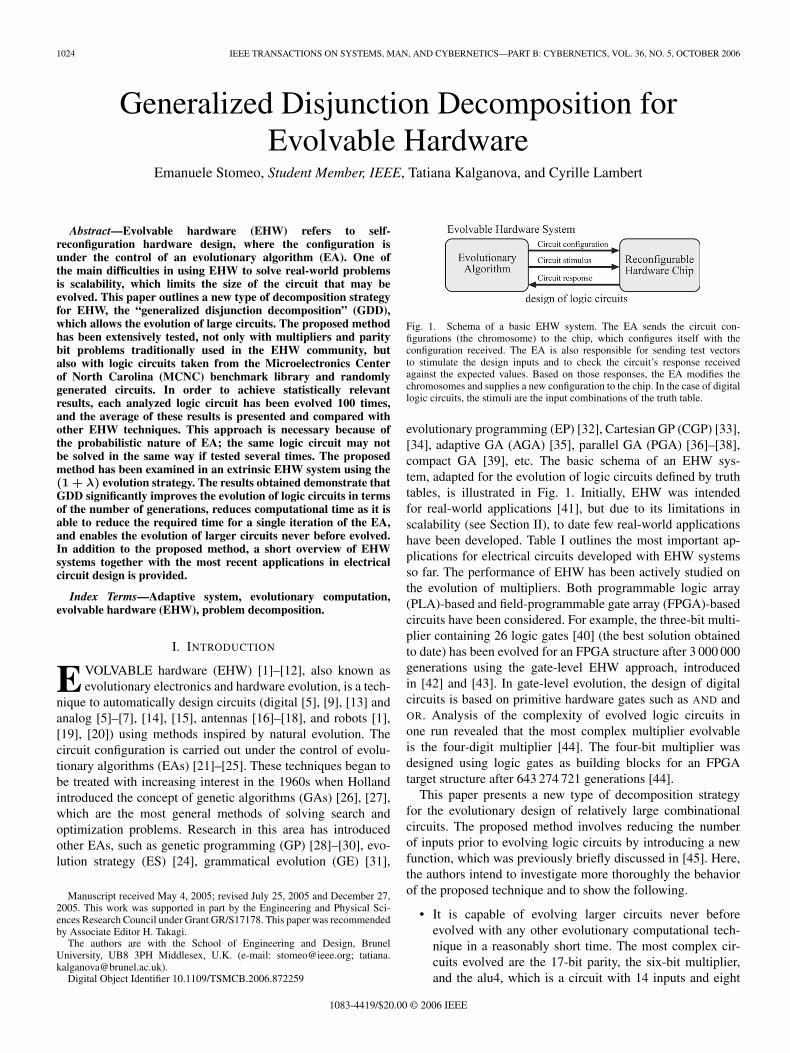
Fig. 1. Schema of a basic EHW system. The EA sends the circuit con-figurations (the chromosome) to the chip, which configures itself with theconfiguration received. The EA is also responsible for sending test vectorsto stimulate the design inputs and to check the circuit’s response receivedagainst the expected values. Based on those responses, the EA modifies thechromosomes and supplies a new configuration to the chip. In the case of digitallogic circuits, the stimuli are the input combinations of the truth table.
evolutionary programming (EP) [32], Cartesian GP (CGP) [33],[34], adaptive GA (AGA) [35], parallel GA (PGA) [36]–[38],compact GA [39], etc. The basic schema of an EHW sys-tem, adapted for the evolution of logic circuits defined by truthtables, is illustrated in Fig. 1. Initially, EHW was intendedfor real-world applications [41], but due to its limitations inscalability (see Section II), to date few real-world applicationshave been developed. Table I outlines the most important ap-plications for electrical circuits developed with EHW systemsso far. The performance of EHW has been actively studied onthe evolution of multipliers. Both programmable logic array(PLA)-based and field-programmable gate array (FPGA)-basedcircuits have been considered. For example, the three-bit multi-plier containing 26 logic gates [40] (the best solution obtainedto date) has been evolved for an FPGA structure after 3 000 000generations using the gate-level EHW approach, introducedin [42] and [43]. In gate-level evolution, the design of digitalcircuits is based on primitive hardware gates such as AND andOR. Analysis of the complexity of evolved logic circuits inone run revealed that the most complex multiplier evolvableis the four-digit multiplier [44]. The four-bit multiplier wasdesigned using logic gates as building blocks for an FPGAtarget structure after 643 274 721 generations [44].
This paper presents a new type of decomposition strategyfor the evolutionary design of relatively large combinationalcircuits. The proposed method involves reducing the numberof inputs prior to evolving logic circuits by introducing a newfunction, which was previously briefly discussed in [45]. Here,the authors intend to investigate more thoroughly the behaviorof the proposed technique and to show the following.
• It is capable of evolving larger circuits never beforeevolved with any other evolutionary computational tech-nique in a reasonably short time. The most complex cir-cuits evolved are the 17-bit parity, the six-bit multiplier,and the alu4, which is a circuit with 14 inputs and eight
STOMEO et al.: GENERALIZED DISJUNCTION DECOMPOSITION FOR EVOLVABLE HARDWARE 1025
TABLE IMAIN ELECTRICAL CIRCUITS DESIGNED WITH EHW SYSTEMS
outputs taken from the Microelectronics Center of NorthCarolina (MCNC) library [81].
• It is able to significantly reduce the number of generationsrequired to evolve digital logic circuits and to reach higherfitness values, which result in better optimized circuits,although the research presented in this paper concentratesonly on the evolution of fully functional circuits ratherthan on the optimization.
The method presented here therefore breaks through thescalability barrier and opens up new opportunities in the designand application of evolvable combinational electrical circuits.The significance of this paper lies in the potential for EHWto contribute to the design of electrical circuits by removinghuman intervention and associated costs. Not only electrical
circuits but also antennas and robot controllers could be auto-matically designed without the need for human inputs. Further-more, EHW, because of its basis in EAs, could adapt itself tochange task requirements and optimize its performance, whichwould be particularly desirable where human intervention isunfeasible or very expensive. Despite recent advancements inresearch and technology, a number of issues remain unresolved,including the following.
• Reducing the number of logic gates, which is quite high ifcompared with hand design circuits.
• Increasing the evolvability [46]–[49]. Evolvability, asdefined in [52] is the ability of the genetic opera-tor/representation scheme to produce offsprings that arefitter than their parents.
1026 IEEE TRANSACTIONS ON SYSTEMS, MAN, AND CYBERNETICS—PART B: CYBERNETICS, VOL. 36, NO. 5, OCTOBER 2006
• Fault tolerance [6], [13], [49]–[51].• Maintainability and comprehensibility of the evolved cir-
cuit [53]. Maintainability as in [54] is the system’s abil-ity to preserve and improve its performance and faulttolerance properties and to adjust them to the varyingenvironment.
This paper is organized as follows. The next section consid-ers the problems of scalability and stalling effect in the fitnessfunction. In Section III, a brief description of the benchmarksused to carry out the simulations is presented. Section IVillustrates the basis of an extrinsic EHW system (first intro-duced in [55]), together with the EA implemented, the chromo-some encoded, and the fitness function applied to the system.Furthermore, a short introduction on bidirectional incrementalevolution (BIE) is given. Section V outlines the limitations ofan EHW system by testing the evolution of several logic circuitsof different complexities. Section VI proposes the generalizeddisjunction decomposition (GDD) for EHW, together with astudy case. Section VII gives the parameter’s setting for theexperiments carried out with the proposed method. Section VIIIillustrates the experimental results of the proposed methodtogether with BIE. The proposed method is compared againstother techniques and the advantages and disadvantages are out-lined. Section IX concludes this paper and provides a summaryof key conclusions.
II. SCALABILITY PROBLEMS AND STALLING EFFECT
IN THE FITNESS FUNCTION
In this section, the problem of scalability [1], [49], [60],[85]–[87] and the stalling effect in the fitness function for anEHW system are outlined. The word scalable, or scalability, aswritten in [93], has been used to describe how the size of theproblem will influence the performance of algorithms. EHWsystems are not scalable because of the genotype length, whichincreases with problem size [61], and the time required forfitness evaluation, which increases rapidly with the size of thedesired evolvable circuits.
The length of the genotype increases with the number oflogic gates used during the evolution and the level of permit-ted connectivity between logic gates. The time necessary forfitness evaluation is not scalable because it is exponentiallydependent on the number of inputs of the system that should beevolved. If the number of inputs increases linearly, the numberof input–output combinations, which represent the descriptionof the digital logic circuits problem, increases by a power of2. Consequently, as the number of inputs increases, the systemneeds more time to produce new potential solutions, to evaluatethem, and to select new individuals. The time required for theevolutionary process is given by the time for a single iteration(µ) multiplied by the total number of iterations Ngen needed tosolve the problem, i.e.,
Ttot = µNgen. (1)
A possible method to reduce the total time for the evo-lutionary process is to introduce a new algorithm to reducethe number of generations needed or to reduce the time for a
single iteration. The method proposed in this paper is able toaccomplish both reductions.
Recently, the scalability problem has been investigatedmainly in the following areas.
• Developing multievolutionary processes using the princi-ples of problem decomposition [68], [79], [84].
• Improving the genotype–phenotype mapping on biolog-ical development [85], [86], [88], [89], [91], [92]. Thisapproach is achieving good results, for example, Gordon[86] was able to evolve a 12-bit parity function.
One approach to tackling scalability is the function-levelEHW proposed in [42], [43], [64], and [65]. In function-levelevolution, the synthesis of circuits is done based on higherfunctions as sin, adders, etc., instead of primitive gates such asAND and OR. Function-level evolution has proven to be success-ful in achieving the evolution of relatively complex tasks [64].However, one of the main weaknesses of this approach is that itstill requires human intervention to select the most appropriatefunctions for specific problems. Function-level evolution hasbeen further extended in [67]. Although the proposed approachsignificantly reduces the number of generations required toobtain a fully functional solution, the evolvability [46], [48],[49] of logic circuits with a higher number of inputs remainsthe central issue.
Using decomposition strategies, a number of approachesintended to overcome scalability have been introduced, such asdivide-and-conquer for EHW [79] and BIE [62], [84].
The divide-and-conquer method, also called increased com-plexity evolution [80], has been introduced to reduce the searchspace, which allows complete evolution of logic circuits withten inputs by introducing the training vector and partitionedtraining set [70]. However, a significant weakness is alsopresent, that is, the difficulties in defining the fitness func-tion for the initial stages of evolution, which makes it lesssuitable for completely automatic systems. Furthermore, thismethod creates an unconditional constraint on the system: thetop-down solving approach that does not allow the discoveryof new designs. BIE [62], [84] is a completely automaticdecomposition method that does not require any knowledgefrom the designer. However, it is not scalable to really largecircuits due to the limitations of EHW-oriented output andShannon decompositions (see Fig. 2). The first attempt to useBIE in EHW was achieved by the evolution of a seven-inputten-output logic function from MCNC benchmark [81]. BIEhas been further improved by the introduction of new assem-bling techniques [82]. Although BIE and increased complexityevolution have proven to be successful in the evolution oflogic circuits, the scalability problem remains to be one ofthe main issues in achieving the evolution of relatively largelogic circuits in a reasonably short time. This paper addressesthat issue.
The problem of stalling effect in fitness functions is re-lated to the nonimprovement of the fitness values during theevolutionary process. Fig. 3 shows the stalling effect of thefitness function during an evolutionary process for evolving a
STOMEO et al.: GENERALIZED DISJUNCTION DECOMPOSITION FOR EVOLVABLE HARDWARE 1027
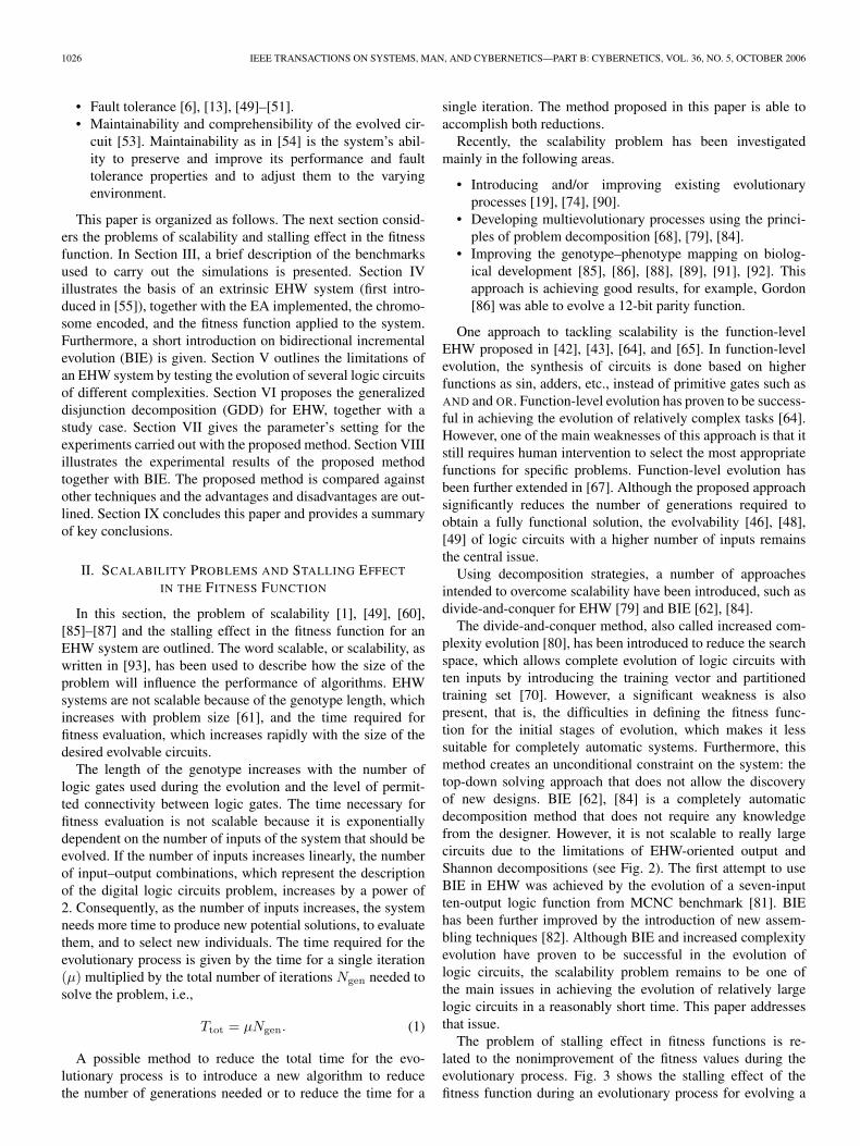
Fig. 2. Decomposition of logic circuits. (a) Initial system with n inputs and m outputs. (b) Output decomposition. (c) Shannon decomposition [62].
Fig. 3. Stalling effect in fitness function. Stalling effect in fitness function refers to a nonimprovement of the fitness value during the evolution process. In thisgraph, the stalling effect during an evolution of a seven-bit adder is shown.
seven-bit adder using (1 + λ) ES. It may be observed that whenthe fitness function reaches 82.8% the stalling effect occurs. Itmeans that the EA chosen and/or the initial configuration forsolving that particular problem are not suitable.
III. BENCHMARKS
In this paper, several combinational circuits have been con-sidered for use in simulations. First of all, the benchmarksusually used within the EHW community were considered, i.e.,multipliers, used in [13], [44], [49], [70], [88], [94], and [95],and parity circuits, used in [30], [85]–[87], and [108].
Then, the MCNC benchmark [81], usually used by the logicdesign community, was taken into account. Finally, simple logiccircuits with randomly generated truth tables were considered.The rationale for choosing several benchmarks is that it isbeneficial to be able to compare the method proposed here withother existing methods in order to establish its contribution.
IV. EXTRINSIC EHW
In this section, an explanation of the system used to evolvecombinational logic circuits is given. The EA that has been usedand the chromosome representations, fitness function, geneticoperators, and BIE are presented.
A. Description of the Algorithm
The EA used for the simulation is the well-known (1 + λ)ES already tested for its in performance in [24], [25], [33],and [83], where λ represents the population size (see Fig. 4).First, all the chromosomes are randomly initialized. Second, thefitness value of each individual is computed. Third, the fittestindividual is selected. Fourth, the previously selected individualis used to test if the conditions to stop the process have beenmet. These conditions are: the fitness value of the chromosomeis 100% or the number of generations has reached the maximumvalue set by the user for that particular experiment. If theconditions are not met, a new population will be generated bymutating the best chromosome (selected at the third step) λtimes in order to obtain other λ individuals. In the next cycle, allλ newly created chromosomes are evaluated, the fitness valueof each of them is compared with the fitness value of the bestchromosome of the previous generation, and the best of these(1 + λ) individuals is selected.
B. Chromosome Encoding
The chromosome defines the structure of the logic circuit andthe connectivity between logic gates. In our approach, the logiccircuit has been presented as a rectangular array of logic cells.The type of each logic cell is randomly chosen from the set of
1028 IEEE TRANSACTIONS ON SYSTEMS, MAN, AND CYBERNETICS—PART B: CYBERNETICS, VOL. 36, NO. 5, OCTOBER 2006
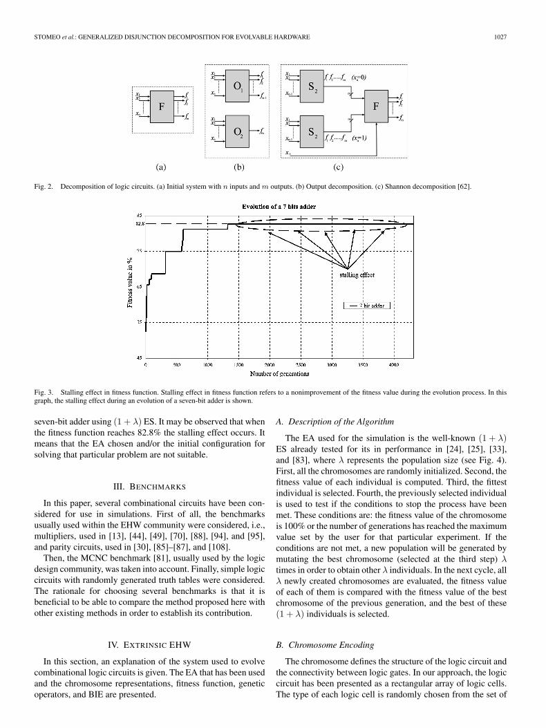
Fig. 4. Schema of (1 + λ) ES.
Fig. 5. Chromosome’s structure. (a) Geometry level. (b) Functional level. (c) Connection level. (d) Example of a chromosome at the connection level. In thisexample, the logic gate identified by the number 32 is considered. This logic gate has five inputs, which are taken from the outputs of the logic gates identified bythe numbers 3, 5, 11, 7, and 27.
AND, OR, XOR, NOT, and MUX, where MUX is a multiplexerwith two inputs and one control signal. The chromosome hasbeen represented by a three-level structure.
• Geometry level [see Fig. 5(a)] contains information aboutthe number of rows, the number of columns of the rectan-gular array, and the degree of internal connectivity, alsoreferred to as level-back parameter [34]. The level-backparameter defines how many columns of cells to the leftof the current column may have their outputs connected tothe inputs of the current cell.
• Functional level [see Fig. 5(b)] describes the array of cellsand determines the circuit’s outputs.
• Connection level [see Fig. 5(c)] represents the structure ofeach cell in the circuit and the connections between them.
In Fig. 6, an example of chromosome encoding for a circuitlayout with three inputs and two outputs is given. The circuitlayout is a circuit with two rows and three columns, and thelevel back is set to three; therefore, the chromosome at geome-try level is “2,” “3,” and “3.” The chromosome at functionallevel encodes the array of cells. For example, the logic gateidentified by the output “3” is an XOR gate. XOR is encoded with Fig. 6. Example of a chromosome encoding.
STOMEO et al.: GENERALIZED DISJUNCTION DECOMPOSITION FOR EVOLVABLE HARDWARE 1029
the number “9.” Thus, the first two cells of this chromosomeare “3” and “9.” The logic gate with output “4” is an AND gate(encoded with the number “7”); thus, the next two cells of thefunctional level’s chromosome are “4” and “7.” All the otherlogic gates are encoded in the same way. The last two cells ofthat chromosome contain the outputs of the circuit (in this case,the outputs of the circuit are taken from the output of the logicgates “4” and “5”).
The chromosome at connection level identifies the logicgates, its number of inputs, and from which gate’s outputthose inputs are taken. The chromosome of the first logic gate(first row, first column) contains “3” (which is the logic gateidentifier), then “2” (which means that that circuit has twoinputs), and then “0” and “1,” which means that one input istaken from X0 and the other from X1. All the other five logicgates are encoded in the same way.
C. Fitness Function
The fitness function evaluates the evolved circuits in termsof their functionality. The fitness function selected for theexperiments has two main criteria, namely; 1) design, and, oncethe circuit is fully functionally evolved, 2) optimization, whichleads to reduced numbers of active logic gates used in the circuitconfiguration.
The fitness function ftot is calculated as
ftot ={
f1, if ftot ≤ 100 designf1 + f2, if ftot > 100 optimization
(2)
where f1 is a design criterion that defines the percentageof correct output bits produced by the evolved circuit afterthe application of all possible input combinations. f2 is theoptimization criterion for the optimization stage.
The fitness function for the functionality of the evolvedcircuit f1, or the so-called design criterion, has been calcu-lated as
f1 = 100 − 100mp
2n−1∑fc=0
m−1∑i=0
|yi − di| (3)
where m and n are the number of outputs and inputs ofthe given logic function, respectively, p is the number ofinput–output combinations, yi is the ith digit of the outputcombination produced by the evaluation of the circuit, di isthe desired output for the fitness case fc, and |yi − di| is theabsolute difference between the actual and the required outputs.
The fitness function for the optimization stage has beencalculated below, where NLG is the number of total logic gatespresent in the chromosome and is equal to the number ofrows multiplied by the number of columns of the chromosome.Nmax
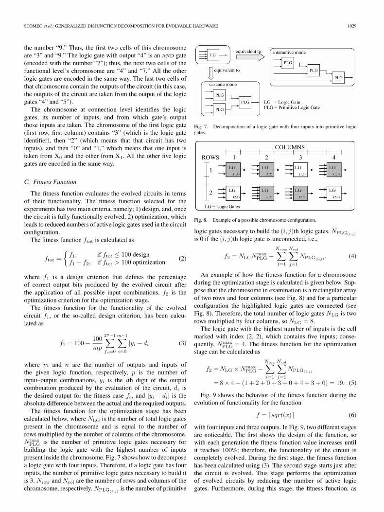
PLG is the number of primitive logic gates necessary forbuilding the logic gate with the highest number of inputspresent inside the chromosome. Fig. 7 shows how to decomposea logic gate with four inputs. Therefore, if a logic gate has fourinputs, the number of primitive logic gates necessary to build itis 3. Nrow and Ncol are the number of rows and columns of thechromosome, respectively. NPLG(i,j) is the number of primitive
Fig. 7. Decomposition of a logic gate with four inputs into primitive logicgates.
Fig. 8. Example of a possible chromosome configuration.
logic gates necessary to build the (i, j)th logic gates. NPLG(i,j)
is 0 if the (i, j)th logic gate is unconnected, i.e.,
f2 = NLGNmaxPLG −
Nrow∑1=1
Ncol∑j=1
NPLG(i,j) . (4)
An example of how the fitness function for a chromosomeduring the optimization stage is calculated is given below. Sup-pose that the chromosome in examination is a rectangular arrayof two rows and four columns (see Fig. 8) and for a particularconfiguration the highlighted logic gates are connected (seeFig. 8). Therefore, the total number of logic gates NLG is tworows multiplied by four columns, so NLG = 8.
The logic gate with the highest number of inputs is the cellmarked with index (2, 2), which contains five inputs; conse-quently, Nmax
PLG = 4. The fitness function for the optimizationstage can be calculated as
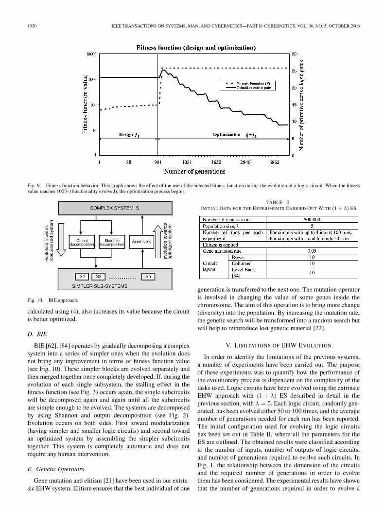
Fig. 9 shows the behavior of the fitness function during theevolution of functionality for the function
f = �sqrt(x)� (6)
with four inputs and three outputs. In Fig. 9, two different stagesare noticeable. The first shows the design of the function, sowith each generation the fitness function value increases untilit reaches 100%; therefore, the functionality of the circuit iscompletely evolved. During the first stage, the fitness functionhas been calculated using (3). The second stage starts just afterthe circuit is evolved. This stage performs the optimizationof evolved circuits by reducing the number of active logicgates. Furthermore, during this stage, the fitness function, as
1030 IEEE TRANSACTIONS ON SYSTEMS, MAN, AND CYBERNETICS—PART B: CYBERNETICS, VOL. 36, NO. 5, OCTOBER 2006
Fig. 9. Fitness function behavior. This graph shows the effect of the use of the selected fitness function during the evolution of a logic circuit. When the fitnessvalue reaches 100% (functionality evolved), the optimization process begins.
Fig. 10. BIE approach.
calculated using (4), also increases its value because the circuitis better optimized.
D. BIE
BIE [62], [84] operates by gradually decomposing a complexsystem into a series of simpler ones when the evolution doesnot bring any improvement in terms of fitness function value(see Fig. 10). These simpler blocks are evolved separately andthen merged together once completely developed. If, during theevolution of each single subsystem, the stalling effect in thefitness function (see Fig. 3) occurs again, the single subcircuitswill be decomposed again and again until all the subcircuitsare simple enough to be evolved. The systems are decomposedby using Shannon and output decomposition (see Fig. 2).Evolution occurs on both sides. First toward modularization(having simpler and smaller logic circuits) and second towardan optimized system by assembling the simpler subcircuitstogether. This system is completely automatic and does notrequire any human intervention.
E. Genetic Operators
Gene mutation and elitism [21] have been used in our extrin-sic EHW system. Elitism ensures that the best individual of one
TABLE IIINITIAL DATA FOR THE EXPERIMENTS CARRIED OUT WITH (1 + λ) ES
generation is transferred to the next one. The mutation operatoris involved in changing the value of some genes inside thechromosome. The aim of this operation is to bring more change(diversity) into the population. By increasing the mutation rate,the genetic search will be transformed into a random search butwill help to reintroduce lost genetic material [22].
V. LIMITATIONS OF EHW EVOLUTION
In order to identify the limitations of the previous systems,a number of experiments have been carried out. The purposeof these experiments was to quantify how the performance ofthe evolutionary process is dependent on the complexity of thetasks used. Logic circuits have been evolved using the extrinsicEHW approach with (1 + λ) ES described in detail in theprevious section, with λ = 5. Each logic circuit, randomly gen-erated, has been evolved either 50 or 100 times, and the averagenumber of generations needed for each run has been reported.The initial configuration used for evolving the logic circuitshas been set out in Table II, where all the parameters for theES are outlined. The obtained results were classified accordingto the number of inputs, number of outputs of logic circuits,and number of generations required to evolve such circuits. InFig. 1, the relationship between the dimension of the circuitsand the required number of generations in order to evolvethem has been considered. The experimental results have shownthat the number of generations required in order to evolve a
STOMEO et al.: GENERALIZED DISJUNCTION DECOMPOSITION FOR EVOLVABLE HARDWARE 1031
Fig. 11. Average number of generations required to evolve logic circuits withn inputs and m outputs using (1 + λ) ES.
logic circuit is mainly dependent on the number of inputs. Thesystem set-up together with the EHW algorithm used was ableto evolve only the circuit for which the results are given inFig. 11. The considered system has not been able to evolvemore complex logic circuits. Based on the obtained results, onemay conclude that there is a need for the development of amethod that would concentrate on the input decomposition forEHW systems. That method is proposed in the next section. Theexperimental results prove that such a method will tackle thescalability problem better than the methods focused on outputdecomposition. This paper is devoted to proposing that method.
Therefore, a new system that is capable of reducing thenumber of required generations and at the same time improvingthe fitness values and evolving larger logic circuits has beenintroduced.
VI. GENERALIZED DISJUNCTION DECOMPOSITION
In this section, the proposed method, GDD, which speedsup the evolutionary process and optimizes the logic circuit, isexplained. This method improves the scalability for evolvinglogic circuits. This method has been introduced as a result ofthe limitation of EHW evolution demonstrated in the previoussection: the number of generations required to evolve a circuitis mainly dependent on the number of inputs rather than on thenumber of outputs.
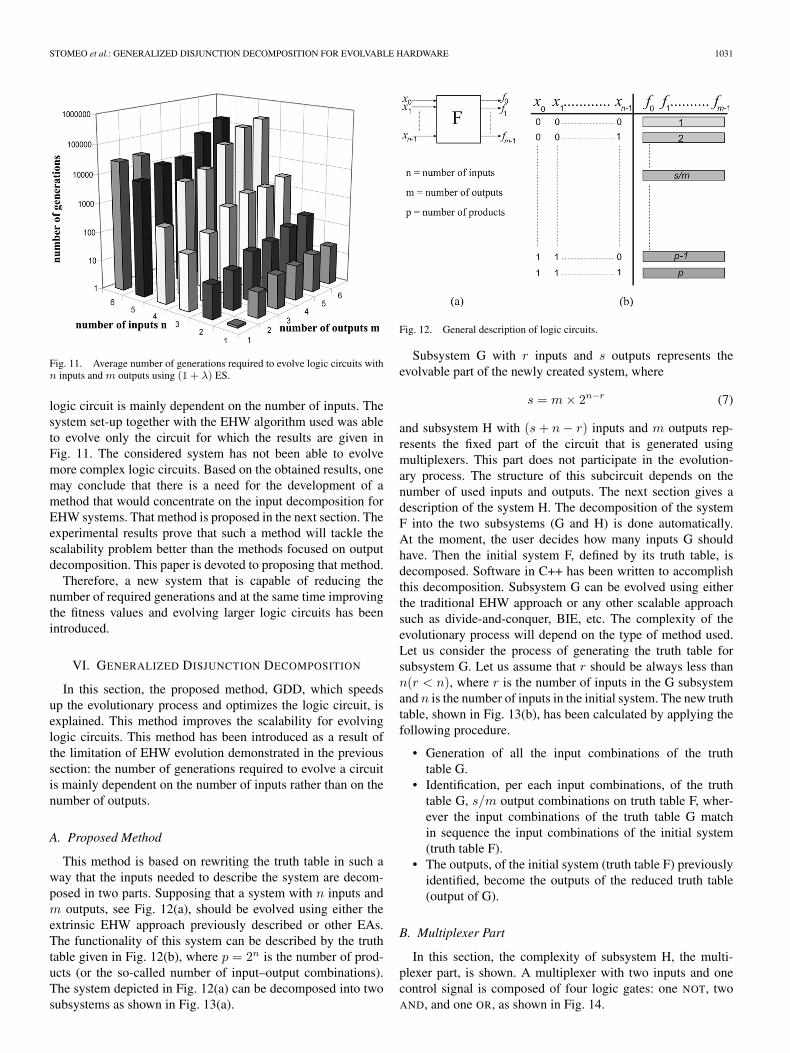
A. Proposed Method
This method is based on rewriting the truth table in such away that the inputs needed to describe the system are decom-posed in two parts. Supposing that a system with n inputs andm outputs, see Fig. 12(a), should be evolved using either theextrinsic EHW approach previously described or other EAs.The functionality of this system can be described by the truthtable given in Fig. 12(b), where p = 2n is the number of prod-ucts (or the so-called number of input–output combinations).The system depicted in Fig. 12(a) can be decomposed into twosubsystems as shown in Fig. 13(a).
Fig. 12. General description of logic circuits.
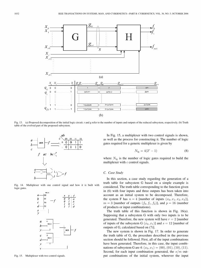
Subsystem G with r inputs and s outputs represents theevolvable part of the newly created system, where
s = m × 2n−r (7)
and subsystem H with (s + n − r) inputs and m outputs rep-resents the fixed part of the circuit that is generated usingmultiplexers. This part does not participate in the evolution-ary process. The structure of this subcircuit depends on thenumber of used inputs and outputs. The next section gives adescription of the system H. The decomposition of the systemF into the two subsystems (G and H) is done automatically.At the moment, the user decides how many inputs G shouldhave. Then the initial system F, defined by its truth table, isdecomposed. Software in C++ has been written to accomplishthis decomposition. Subsystem G can be evolved using eitherthe traditional EHW approach or any other scalable approachsuch as divide-and-conquer, BIE, etc. The complexity of theevolutionary process will depend on the type of method used.Let us consider the process of generating the truth table forsubsystem G. Let us assume that r should be always less thann(r < n), where r is the number of inputs in the G subsystemand n is the number of inputs in the initial system. The new truthtable, shown in Fig. 13(b), has been calculated by applying thefollowing procedure.
• Generation of all the input combinations of the truthtable G.
• Identification, per each input combinations, of the truthtable G, s/m output combinations on truth table F, wher-ever the input combinations of the truth table G matchin sequence the input combinations of the initial system(truth table F).
• The outputs, of the initial system (truth table F) previouslyidentified, become the outputs of the reduced truth table(output of G).
B. Multiplexer Part
In this section, the complexity of subsystem H, the multi-plexer part, is shown. A multiplexer with two inputs and onecontrol signal is composed of four logic gates: one NOT, twoAND, and one OR, as shown in Fig. 14.
1032 IEEE TRANSACTIONS ON SYSTEMS, MAN, AND CYBERNETICS—PART B: CYBERNETICS, VOL. 36, NO. 5, OCTOBER 2006
Fig. 13. (a) Proposed decomposition of the initial logic circuit. r and g refer to the number of inputs and outputs of the reduced subsystem, respectively. (b) Truthtable of the evolved part of the proposed subsystem.
Fig. 14. Multiplexer with one control signal and how it is built withlogic gates.
Fig. 15. Multiplexer with two control signals.
In Fig. 15, a multiplexer with two control signals is shown,as well as the process for constructing it. The number of logicgates required for a generic multiplexer is given by
Nlg = 4(2c − 1) (8)
where Nlg is the number of logic gates required to build themultiplexer with c control signals.
C. Case Study
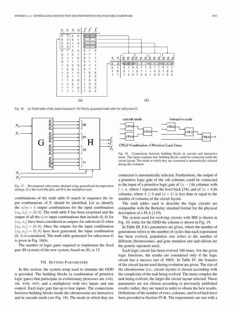
In this section, a case study regarding the generation of atruth table for subsystem G based on a simple example isconsidered. The truth table corresponding to the function givenin (6) with four inputs and three outputs has been taken intoaccount as an initial system to be decomposed. Therefore,the system F has n = 4 [number of inputs (x0, x1, x2, x3)],m = 3 [number of outputs (f0, f1, f2)], and p = 16 (numberof products or input combinations).
The truth table of this function is shown in Fig. 16(a).Supposing that a subsystem G with only two inputs is to begenerated. Therefore, the new system will have r = 2 [numberof inputs of the subsystem G (x0, x1)] and s = 12 [number ofoutputs of G, calculated based on (7)].
The new system is shown in Fig. 17. In order to generatethe truth table of G, the procedure described in the previoussection should be followed. First, all of the input combinationshave been generated. Therefore, in this case, the input combi-nations of subsystem G are 4: (x0, x1) = (00), (01), (10), (11).Second, for each input combination generated, the s/m out-put combinations of the initial system, wherever the input
STOMEO et al.: GENERALIZED DISJUNCTION DECOMPOSITION FOR EVOLVABLE HARDWARE 1033
Fig. 16. (a) Truth table of the initial function F. (b) Newly generated truth table for subsystem G.
Fig. 17. Decomposed subsystems obtained using generalized decompositionstrategy. G is the evolvable part, and H is the multiplexer part.
combinations of the truth table G match in sequence the in-put combinations of F, should be identified. Let us identifythe s/m = 4 output combinations for the input combination(x0, x1) = (0, 0). The truth table F has been examined and theoutput of all the s/m input combinations that include (0, 0) for(x0, x1) have been considered as outputs for subcircuit G when(x0, x1) = (0, 0). Once the outputs for the input combination(x0, x1) = (0, 0) have been generated, the input combination(0, 1) is considered. The truth table generated for subsystem Gis given in Fig. 16(b).
The number of logic gates required to implement the fixedpart (H-system) of the new system, based on (8), is 12.
VII. SETTING PARAMETERS
In this section, the system setup used to simulate the GDDis provided. The building blocks (a combination of primitivelogic gates) that participate in evolutionary processes are AND,OR, XOR, NOT, and a multiplexer with two inputs and onecontrol. Each logic gate has up to four inputs. The connectionsbetween building blocks inside the chromosome are interactiveand in cascade mode (see Fig. 18). The mode in which they are
Fig. 18. Connections between building blocks in cascade and interactivemode. This figure explains how building blocks could be connected inside thecircuit layout. The mode in which they are connected is automatically selectedduring the evolution.
connected is automatically selected. Furthermore, the output ofa primitive logic gate of the nth columns could be connectedto the input of a primitive logic gate of (n − l)th columns withl < n, where l represents the level back [34], and of (n + k)thcolumns, where k ≥ 0 and (n + k) is less than or equal to thenumber of columns of the circuit layout.
The truth tables used to describe the logic circuits arecompatible with the Berkeley standard format for the physicaldescription of a PLA [119].
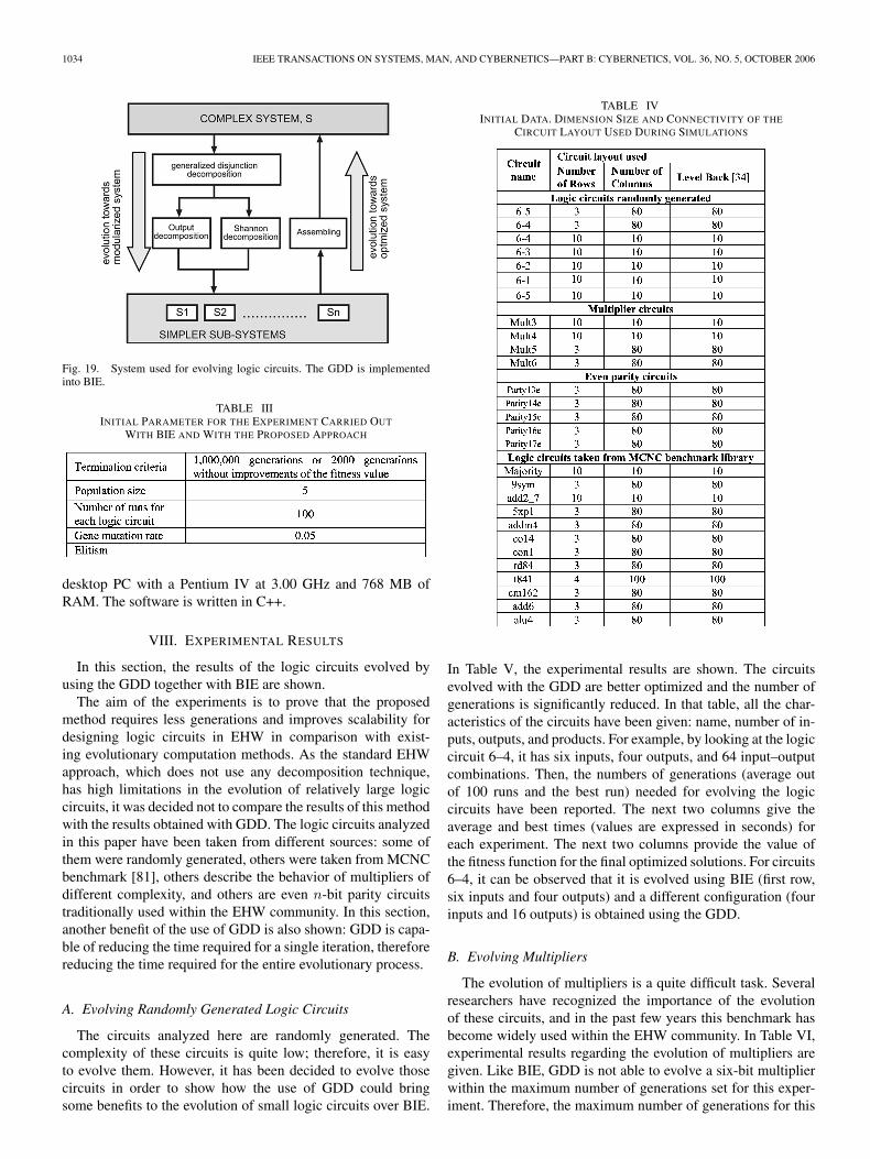
The system used for evolving circuits with BIE is shown inFig. 10, while for the GDD the schema is shown in Fig. 19.
In Table III, EA’s parameters are given, where the number ofgenerations refers to the number of cycles that each experimenthas been evolved, population size refers to the number ofdifferent chromosomes, and gene mutation rate and elitism arethe genetic operators used.
Each logic circuit has been evolved 100 times. For the givenlogic functions, the results are considered only if the logiccircuit has a success rate of 100%. In Table IV, the featuresof the circuit layout used during evolution are given. The size ofthe chromosome (i.e., circuit layout) is chosen according withthe complexity of the task being evolved. The more complex thetask being evolved, the larger the circuit layout selected. Thoseparameters are not chosen according to previously publishedresults; rather, they are tuned in order to obtain the best results.Definitions of the number of rows, columns, and level back havebeen provided in Section IV-B. The experiments are run with a
1034 IEEE TRANSACTIONS ON SYSTEMS, MAN, AND CYBERNETICS—PART B: CYBERNETICS, VOL. 36, NO. 5, OCTOBER 2006
Fig. 19. System used for evolving logic circuits. The GDD is implementedinto BIE.
TABLE IIIINITIAL PARAMETER FOR THE EXPERIMENT CARRIED OUT
WITH BIE AND WITH THE PROPOSED APPROACH
desktop PC with a Pentium IV at 3.00 GHz and 768 MB ofRAM. The software is written in C++.
VIII. EXPERIMENTAL RESULTS
In this section, the results of the logic circuits evolved byusing the GDD together with BIE are shown.
The aim of the experiments is to prove that the proposedmethod requires less generations and improves scalability fordesigning logic circuits in EHW in comparison with exist-ing evolutionary computation methods. As the standard EHWapproach, which does not use any decomposition technique,has high limitations in the evolution of relatively large logiccircuits, it was decided not to compare the results of this methodwith the results obtained with GDD. The logic circuits analyzedin this paper have been taken from different sources: some ofthem were randomly generated, others were taken from MCNCbenchmark [81], others describe the behavior of multipliers ofdifferent complexity, and others are even n-bit parity circuitstraditionally used within the EHW community. In this section,another benefit of the use of GDD is also shown: GDD is capa-ble of reducing the time required for a single iteration, thereforereducing the time required for the entire evolutionary process.
A. Evolving Randomly Generated Logic Circuits
The circuits analyzed here are randomly generated. Thecomplexity of these circuits is quite low; therefore, it is easyto evolve them. However, it has been decided to evolve thosecircuits in order to show how the use of GDD could bringsome benefits to the evolution of small logic circuits over BIE.
TABLE IVINITIAL DATA. DIMENSION SIZE AND CONNECTIVITY OF THE
CIRCUIT LAYOUT USED DURING SIMULATIONS
In Table V, the experimental results are shown. The circuitsevolved with the GDD are better optimized and the number ofgenerations is significantly reduced. In that table, all the char-acteristics of the circuits have been given: name, number of in-puts, outputs, and products. For example, by looking at the logiccircuit 6–4, it has six inputs, four outputs, and 64 input–outputcombinations. Then, the numbers of generations (average outof 100 runs and the best run) needed for evolving the logiccircuits have been reported. The next two columns give theaverage and best times (values are expressed in seconds) foreach experiment. The next two columns provide the value ofthe fitness function for the final optimized solutions. For circuits6–4, it can be observed that it is evolved using BIE (first row,six inputs and four outputs) and a different configuration (fourinputs and 16 outputs) is obtained using the GDD.
B. Evolving Multipliers
The evolution of multipliers is a quite difficult task. Severalresearchers have recognized the importance of the evolutionof these circuits, and in the past few years this benchmark hasbecome widely used within the EHW community. In Table VI,experimental results regarding the evolution of multipliers aregiven. Like BIE, GDD is not able to evolve a six-bit multiplierwithin the maximum number of generations set for this exper-iment. Therefore, the maximum number of generations for this
STOMEO et al.: GENERALIZED DISJUNCTION DECOMPOSITION FOR EVOLVABLE HARDWARE 1035
TABLE VEXPERIMENTAL RESULTS FROM BIE AND GDD, WHERE IN, OUT, AND P ARE THE NUMBER OF INPUTS, OUTPUTS, AND PRODUCTS IN THE
GIVEN LOGIC FUNCTION. EACH LOGIC CIRCUIT HAS BEEN EVOLVED 100 TIMES WITH A SUCCESS RATE OF 100%
TABLE VIEXPERIMENTAL RESULTS FROM BIE AND GDD. EACH LOGIC CIRCUIT HAS BEEN EVOLVED 100 TIMES WITH A SUCCESS RATE OF 100%. FOR THE
EVOLUTION OF THE SIX-BIT MULTIPLIER, THE MAXIMUM NUMBER OF GENERATIONS WAS SET TO 3 000 000 BECAUSE OF THE DIFFICULTIES TO
EVOLVE IT. ONLY THREE RUNS HAVE BEEN CARRIED OUT FOR THIS MULTIPLIER AS THE AVERAGE REQUIRED EVOLUTION TIME IS 48.48 h
circuit was increased to 3 000 000. In [117], it has already beenproven for one run that GDD is able to solve this multiplier,but only by using a higher number of generations. The six-bitmultiplier is also evolved using another configuration of GDD,with nine inputs and 96 outputs. Three experiments have beencarried out with this configuration, and the average numberof generations required is 2 536 135 while the average timeper experiment is 32.00 h; a bit less than the configurationwith ten inputs.
C. Evolving Even n-Bit Parity Function
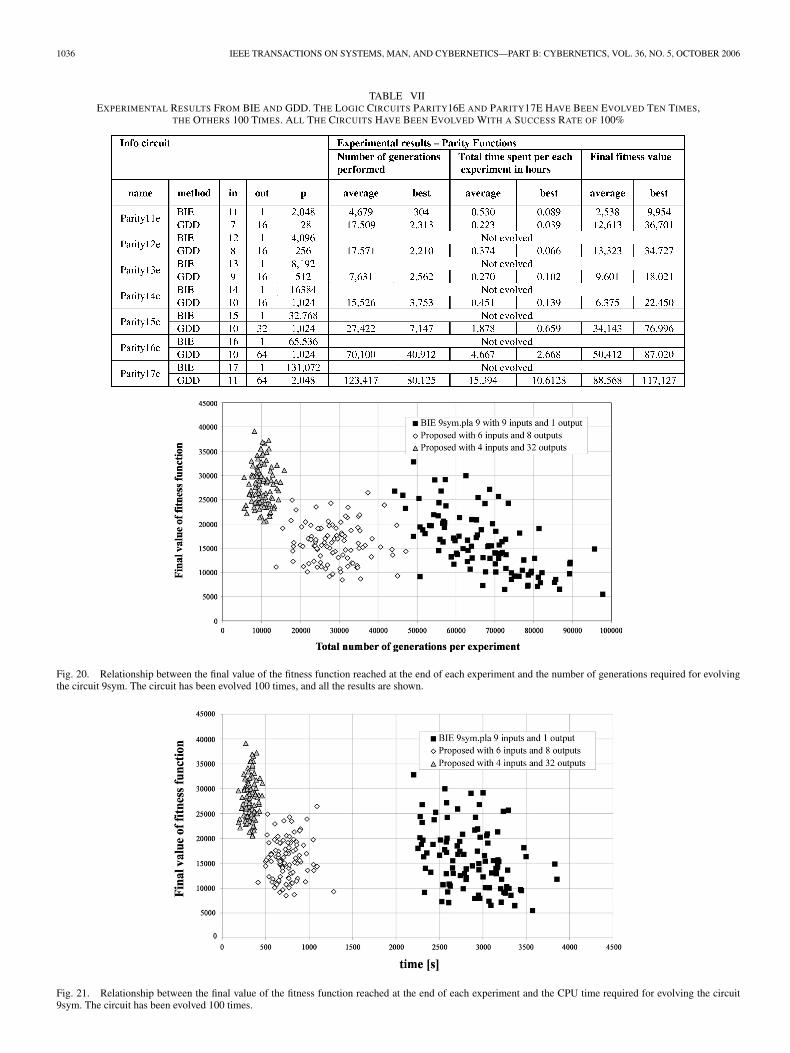
Parity functions are often used to check the accuracy ofstored or transmitted binary data in computers because a changein the value of any one of its arguments toggles the value ofthe function. As a result of this sensitivity to its inputs, theparity function is difficult to learn [29]. This benchmark, as withthe multipliers, is popular within the evolutionary computationcommunity. The even n-bit parity circuit produces a responseequal to the sum modulo 2 of its inputs. Table VII shows theexperimental results for the evolution of those circuits. Fromthat table, it can be observed that with the use of GDD theevolution of a large circuit is feasible. GDD is able to evolve
large even parity bit circuits never evolved before. The bestparity bit circuit successfully evolved previously was presentedin [86], and it was a 12-bit parity circuit. It was evolved usinga developmental model based on a biological map betweengenotype and phenotype.
D. Evolving Logic Circuits From MCNC Benchmark
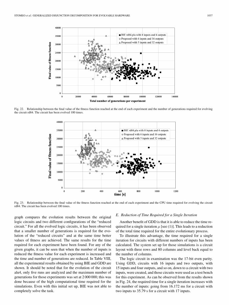
The experimental results reported in this section are thosein relation to the evolution of circuits taken from the MCNCbenchmark [81], [110]. This benchmark was first presentedat the 1990 International Workshop on Layout Synthesis.Since then, several researchers within the GA communityhave used it as a test bench for floor planning [111], cellplacement [112], [113], power consumption [114], etc. It isstill not popular within the EHW community because of thecomplexities of those circuits. However, here, it has been de-cided to evolve those circuits in order to show that GDD hasthe capability to cope with these circuits. Figs. 20–23 showthe relationships between the values of the fitness function, thenumber of generations, and the time spent for each experiment.“Reduced circuit” refers to a circuit that has been obtainedby applying the proposed method to the original circuit. Each
1036 IEEE TRANSACTIONS ON SYSTEMS, MAN, AND CYBERNETICS—PART B: CYBERNETICS, VOL. 36, NO. 5, OCTOBER 2006
TABLE VIIEXPERIMENTAL RESULTS FROM BIE AND GDD. THE LOGIC CIRCUITS PARITY16E AND PARITY17E HAVE BEEN EVOLVED TEN TIMES,
THE OTHERS 100 TIMES. ALL THE CIRCUITS HAVE BEEN EVOLVED WITH A SUCCESS RATE OF 100%
Fig. 20. Relationship between the final value of the fitness function reached at the end of each experiment and the number of generations required for evolvingthe circuit 9sym. The circuit has been evolved 100 times, and all the results are shown.
Fig. 21. Relationship between the final value of the fitness function reached at the end of each experiment and the CPU time required for evolving the circuit9sym. The circuit has been evolved 100 times.
STOMEO et al.: GENERALIZED DISJUNCTION DECOMPOSITION FOR EVOLVABLE HARDWARE 1037
Fig. 22. Relationship between the final value of the fitness function reached at the end of each experiment and the number of generations required for evolvingthe circuit rd84. The circuit has been evolved 100 times.
Fig. 23. Relationship between the final value of the fitness function reached at the end of each experiment and the CPU time required for evolving the circuitrd84. The circuit has been evolved 100 times.
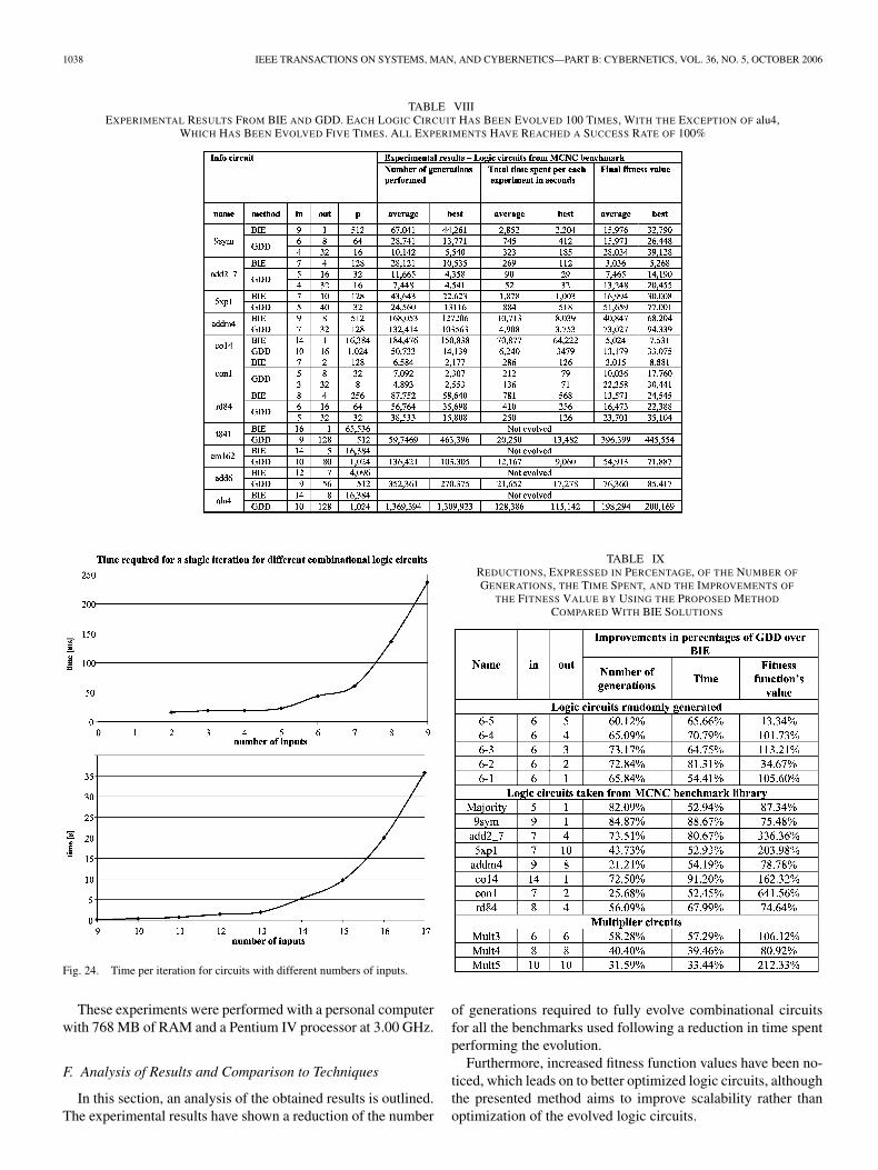
graph compares the evolution results between the originallogic circuits and two different configurations of the “reducedcircuit.” For all the evolved logic circuits, it has been observedthat a smaller number of generations is required for the evo-lution of the “reduced circuits” and at the same time bettervalues of fitness are achieved. The same results for the timerequired for each experiment have been found. For any of thegiven graphs, it can be seen that when the number of inputs isreduced the fitness value for each experiment is increased andthe time and number of generations are reduced. In Table VIII,all the experimental results obtained by using BIE and GDD areshown. It should be noted that for the evolution of the circuitalu4, only five runs are analyzed and the maximum number ofgenerations for those experiments was set at 2 000 000; this wasdone because of the high computational time required for thesimulations. Even with this initial set up, BIE was not able tocompletely solve the task.
E. Reduction of Time Required for a Single Iteration
Another benefit of GDD is that it is able to reduce the time re-quired for a single iteration µ [see (1)]. This leads to a reductionof the total time required for the entire evolutionary process.
To illustrate this advantage, the time required for a singleiteration for circuits with different numbers of inputs has beencalculated. The system set up for those simulations is a circuitlayout with three rows and 80 columns and level back equal tothe number of columns.
The logic circuit in examination was the 17-bit even parity.Using GDD, circuits with 16 inputs and two outputs, with15 inputs and four outputs, and so on, down to a circuit with twoinputs, were created, and those circuits were used as a test benchfor this experiment. As can be observed from the results shownin Fig. 24, the required time for a single iteration increases withthe number of inputs: going from 16.172 ms for a circuit withtwo inputs to 35.79 s for a circuit with 17 inputs.
1038 IEEE TRANSACTIONS ON SYSTEMS, MAN, AND CYBERNETICS—PART B: CYBERNETICS, VOL. 36, NO. 5, OCTOBER 2006
TABLE VIIIEXPERIMENTAL RESULTS FROM BIE AND GDD. EACH LOGIC CIRCUIT HAS BEEN EVOLVED 100 TIMES, WITH THE EXCEPTION OF alu4,
WHICH HAS BEEN EVOLVED FIVE TIMES. ALL EXPERIMENTS HAVE REACHED A SUCCESS RATE OF 100%
Fig. 24. Time per iteration for circuits with different numbers of inputs.
These experiments were performed with a personal computerwith 768 MB of RAM and a Pentium IV processor at 3.00 GHz.
F. Analysis of Results and Comparison to Techniques
In this section, an analysis of the obtained results is outlined.The experimental results have shown a reduction of the number
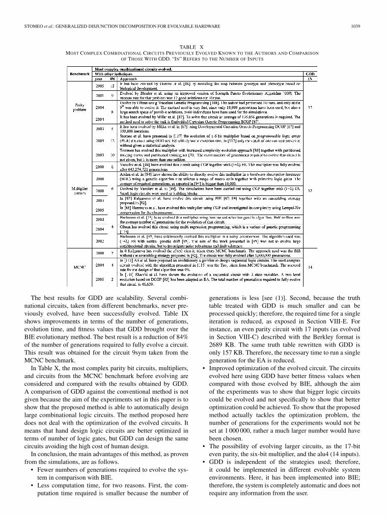
TABLE IXREDUCTIONS, EXPRESSED IN PERCENTAGE, OF THE NUMBER OF
GENERATIONS, THE TIME SPENT, AND THE IMPROVEMENTS OF
THE FITNESS VALUE BY USING THE PROPOSED METHOD
COMPARED WITH BIE SOLUTIONS
of generations required to fully evolve combinational circuitsfor all the benchmarks used following a reduction in time spentperforming the evolution.
Furthermore, increased fitness function values have been no-ticed, which leads on to better optimized logic circuits, althoughthe presented method aims to improve scalability rather thanoptimization of the evolved logic circuits.
STOMEO et al.: GENERALIZED DISJUNCTION DECOMPOSITION FOR EVOLVABLE HARDWARE 1039
TABLE XMOST COMPLEX COMBINATIONAL CIRCUITS PREVIOUSLY EVOLVED KNOWN TO THE AUTHORS AND COMPARISON
OF THOSE WITH GDD. “IN” REFERS TO THE NUMBER OF INPUTS
The best results for GDD are scalability. Several combi-national circuits, taken from different benchmarks, never pre-viously evolved, have been successfully evolved. Table IXshows improvements in terms of the number of generations,evolution time, and fitness values that GDD brought over theBIE evolutionary method. The best result is a reduction of 84%of the number of generations required to fully evolve a circuit.This result was obtained for the circuit 9sym taken from theMCNC benchmark.
In Table X, the most complex parity bit circuits, multipliers,and circuits from the MCNC benchmark before evolving areconsidered and compared with the results obtained by GDD.A comparison of GDD against the conventional method is notgiven because the aim of the experiments set in this paper is toshow that the proposed method is able to automatically designlarge combinational logic circuits. The method proposed heredoes not deal with the optimization of the evolved circuits. Itmeans that hand design logic circuits are better optimized interms of number of logic gates, but GDD can design the samecircuits avoiding the high cost of human design.
In conclusion, the main advantages of this method, as provenfrom the simulations, are as follows.
• Fewer numbers of generations required to evolve the sys-tem in comparison with BIE.
• Less computation time, for two reasons. First, the com-putation time required is smaller because the number of
generations is less [see (1)]. Second, because the truthtable treated with GDD is much smaller and can beprocessed quickly; therefore, the required time for a singleiteration is reduced, as exposed in Section VIII-E. Forinstance, an even parity circuit with 17 inputs (as evolvedin Section VIII-C) described with the Berkley format is2689 KB. The same truth table rewritten with GDD isonly 157 KB. Therefore, the necessary time to run a singlegeneration for the EA is reduced.
• Improved optimization of the evolved circuit. The circuitsevolved here using GDD have better fitness values whencompared with those evolved by BIE, although the aimof the experiments was to show that bigger logic circuitscould be evolved and not specifically to show that betteroptimization could be achieved. To show that the proposedmethod actually tackles the optimization problem, thenumber of generations for the experiments would not beset at 1 000 000, rather a much larger number would havebeen chosen.
• The possibility of evolving larger circuits, as the 17-biteven parity, the six-bit multiplier, and the alu4 (14 inputs).
• GDD is independent of the strategies used; therefore,it could be implemented in different evolvable systemenvironments. Here, it has been implemented into BIE;therefore, the system is completely automatic and does notrequire any information from the user.
1040 IEEE TRANSACTIONS ON SYSTEMS, MAN, AND CYBERNETICS—PART B: CYBERNETICS, VOL. 36, NO. 5, OCTOBER 2006
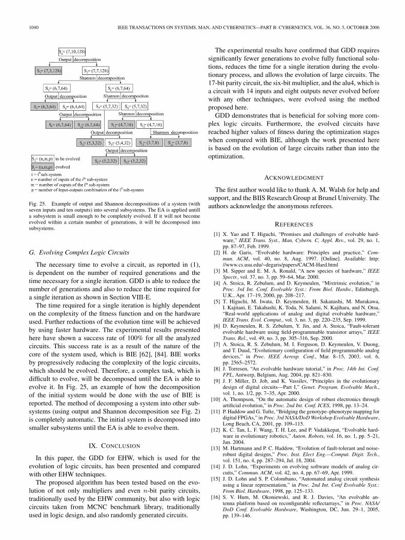
Fig. 25. Example of output and Shannon decompositions of a system (withseven inputs and ten outputs) into several subsystems. The EA is applied untilla subsystem is small enough to be completely evolved. If it will not becomeevolved within a certain number of generations, it will be decomposed intosubsystems.
G. Evolving Complex Logic Circuits
The necessary time to evolve a circuit, as reported in (1),is dependent on the number of required generations and thetime necessary for a single iteration. GDD is able to reduce thenumber of generations and also to reduce the time required fora single iteration as shown in Section VIII-E.
The time required for a single iteration is highly dependenton the complexity of the fitness function and on the hardwareused. Further reductions of the evolution time will be achievedby using faster hardware. The experimental results presentedhere have shown a success rate of 100% for all the analyzedcircuits. This success rate is as a result of the nature of thecore of the system used, which is BIE [62], [84]. BIE worksby progressively reducing the complexity of the logic circuits,which should be evolved. Therefore, a complex task, which isdifficult to evolve, will be decomposed until the EA is able toevolve it. In Fig. 25, an example of how the decompositionof the initial system would be done with the use of BIE isreported. The method of decomposing a system into other sub-systems (using output and Shannon decomposition see Fig. 2)is completely automatic. The initial system is decomposed intosmaller subsystems until the EA is able to evolve them.
IX. CONCLUSION
In this paper, the GDD for EHW, which is used for theevolution of logic circuits, has been presented and comparedwith other EHW techniques.
The proposed algorithm has been tested based on the evo-lution of not only multipliers and even n-bit parity circuits,traditionally used by the EHW community, but also with logiccircuits taken from MCNC benchmark library, traditionallyused in logic design, and also randomly generated circuits.
The experimental results have confirmed that GDD requiressignificantly fewer generations to evolve fully functional solu-tions, reduces the time for a single iteration during the evolu-tionary process, and allows the evolution of large circuits. The17-bit parity circuit, the six-bit multiplier, and the alu4, which isa circuit with 14 inputs and eight outputs never evolved beforewith any other techniques, were evolved using the methodproposed here.
GDD demonstrates that is beneficial for solving more com-plex logic circuits. Furthermore, the evolved circuits havereached higher values of fitness during the optimization stageswhen compared with BIE, although the work presented hereis based on the evolution of large circuits rather than into theoptimization.
ACKNOWLEDGMENT
The first author would like to thank A. M. Walsh for help andsupport, and the BIIS Research Group at Brunel University. Theauthors acknowledge the anonymous referees.
REFERENCES
[1] X. Yao and T. Higuchi, “Promises and challenges of evolvable hard-ware,” IEEE Trans. Syst., Man, Cybern. C, Appl. Rev., vol. 29, no. 1,pp. 87–97, Feb. 1999.
[2] H. de Garis, “Evolvable hardware: Principles and practice,” Com-mun. ACM, vol. 40, no. 8, Aug. 1997. [Online]. Available: http://www.cs.usu.edu/~degaris/papers/CACM-Hard.html
[3] M. Sipper and E. M. A. Ronald, “A new species of hardware,” IEEESpectr., vol. 37, no. 3, pp. 59–64, Mar. 2000.
[4] A. Stoica, R. Zebulum, and D. Keymeulen, “Mixtrinsic evolution,” inProc. 3rd Int. Conf. Evolvable Syst.: From Biol. Hardw., Edinburgh,U.K., Apr. 17–19, 2000, pp. 208–217.
[5] T. Higuchi, M. Iwata, D. Keymeulen, H. Sakanashi, M. Murakawa,I. Kajitani, E. Takahashi, K. Toda, N. Salami, N. Kajihara, and N. Otsu,“Real-world applications of analog and digital evolvable hardware,”IEEE Trans. Evol. Comput., vol. 3, no. 3, pp. 220–235, Sep. 1999.
[6] D. Keymeulen, R. S. Zebulum, Y. Jin, and A. Stoica, “Fault-tolerantevolvable hardware using field-programmable transistor arrays,” IEEETrans. Rel., vol. 49, no. 3, pp. 305–316, Sep. 2000.
[7] A. Stoica, R. S. Zebulum, M. I. Ferguson, D. Keymeulen, V. Duong,and T. Daud, “Evolutionary configuration of field programmable analogdevices,” in Proc. IEEE Aerosp. Conf., Mar. 8–15, 2003, vol. 6,pp. 2565–2572.
[8] J. Torresen, “An evolvable hardware tutorial,” in Proc. 14th Int. Conf.FPL, Antwerp, Belgium, Aug. 2004, pp. 821–830.
[9] J. F. Miller, D. Job, and K. Vassilev, “Principles in the evolutionarydesign of digital circuits—Part I,” Genet. Program. Evolvable Mach.,vol. 1, no. 1/2, pp. 7–35, Apr. 2000.
[10] A. Thompson, “On the automatic design of robust electronics throughartificial evolution,” in Proc. 2nd Int. Conf. ICES, 1998, pp. 13–24.
[11] P. Haddow and G. Tufte, “Bridging the genotype–phenotype mapping fordigital FPGAs,” in Proc. 3rd NASA/DoDWorkshop Evolvable Hardware,Long Beach, CA, 2001, pp. 109–115.
[12] K. C. Tan, L. F. Wang, T. H. Lee, and P. Vadakkepat, “Evolvable hard-ware in evolutionary robotics,” Auton. Robots, vol. 16, no. 1, pp. 5–21,Jan. 2004.
[13] M. Hartmann and P. C. Haddow, “Evolution of fault-tolerant and noise-robust digital designs,” Proc. Inst. Elect Eng.—Comput. Digit. Tech.,vol. 151, no. 4, pp. 287–294, Jul. 18, 2004.
[14] J. D. Lohn, “Experiments on evolving software models of analog cir-cuits,” Commun. ACM, vol. 42, no. 4, pp. 67–69, Apr. 1999.
[15] J. D. Lohn and S. P. Colombano, “Automated analog circuit synthesisusing a linear representation,” in Proc. 2nd Int. Conf Evolvable Syst.:From Biol. Hardware, 1998, pp. 125–133.
[16] S. V. Hum, M. Okoniewski, and R. J. Davies, “An evolvable an-tenna platform based on reconfigurable reflectarrays,” in Proc. NASA/DoD Conf. Evolvable Hardware, Washington, DC, Jun. 29–1, 2005,pp. 139–146.
STOMEO et al.: GENERALIZED DISJUNCTION DECOMPOSITION FOR EVOLVABLE HARDWARE 1041
[17] J. D. Lohn, D. S. Linden, G. S. Hornby, W. F. Kraus, A. Rodriguez, andS. Seufert, “Evolutionary design of an x-band antenna for NASA’s spacetechnology 5 mission,” in Proc. IEEE Antenna Propag. Soc. Int. Symp.USNC/URSI Natl. Radio Sci. Meeting, 2004, vol. 3, pp. 2313–2316.
[18] J. D. Lohn, G. S. Hornby, and D. S. Linden, “An evolved antennafor deployment on NASA’s space technology 5 mission,” in GeneticProgramming Theory and Practice II. Boston, MA: Kluwer, ch. 18.
[19] A. M. Tyrrell, R. A. Krohling, and Y. Zhou, “Evolutionary algorithm forthe promotion of evolvable hardware,” Proc. Inst. Elect. Eng.—Comput.Digit. Tech., vol. 151, no. 4, pp. 267–275, Jul. 18, 2004.
[20] R. J. Terrile, H. Aghazarian, M. I. Ferguson, W. Fink, T. L. Huntsberger,D. Keymeulen, G. Klimeck, M. A. Kordon, L. Seungwon, and P. vonAllmen, “Evolutionary computation technologies for the automated de-sign of space systems,” in Proc. NASA/DoD Conf. Evolvable Hardware,Washington, DC, Jun. 29–1, 2005, pp. 131–138.
[21] D. E. Goldberg,Genetic Algorithm in Search, Optimization and MachineLearning. Reading, MA: Addison-Wesley, 1989.
[22] M. Srinivas and L. M. Patnaik, “Genetic algorithms: A survey,” IEEEJNL Comput., vol. 27, no. 6, pp. 17–26, Jun. 1994.
[23] D. B. Fogel, “What is evolutionary computation? ”IEEE Spectr., vol. 37,no. 2, pp. 26–32, Feb. 2000.
[24] T. Bäck, F. Hoffmeister, and H. P. Schwefel, “A survey of evolutionarystrategies,” in Proc. 4th Int. Conf. Genetic Algorithms, R. Belew andL. Booker, Eds, San Francisco, CA, 1991, pp. 2–9.
[26] J. Holland, Adaptation in Natural and Artificial Systems. Ann Arbor,MI: Univ. of Michigan Press, 1975.
[27] M. D. Vose, The Simple Genetic Algorithm. Cambridge, MA: MITPress, 1999.
[28] J. R. Koza, Genetic Programming: On the Programming of Computersby Means of Natural Selection. Cambridge, MA: MIT Press, 1992.
[29] ——, Genetic Programming II: Automatic Discovery of Reusable Pro-grams. Cambridge, MA: MIT Press, 1994.
[30] R. Riolo and B. Worzel, Genetic Programming Theory and Practice(Genetic Programming), vol. 6. Norwell, MA: Kluwer, 2004, p. 336.
[31] C. Ryan, J. J. Collins, and M. O. Neill, “Grammatical evolution:Evolving programs for an arbitrary language,” in Proc. 1st Eur. Work-shop Genetic Program.. New York: Springer-Verlag, 1998, vol. 1391,pp. 83–95.
[32] L. J. Fogel, A. J. Owens, and M. J. Walsh, Artificial Intelligence ThroughSimulated Evolution. New York: Wiley, 1966.
[33] J. Miller, “An empirical study of the efficiency of learning Booleanfunctions using a Cartesian genetic programming approach,” inProc. Genetic Evol. Comput. Conf., Orlando, FL, Jul. 1999, vol. 1,pp. 1135–1142.
[34] J. F. Miller and P. Thomson, “Cartesian genetic programming,” in Proc.EuroGP, vol. 1802, R. Poli, W. Banzhaf, W. B. Langdon, J. F. Miller,P. Nordin, and T. C. Forgaty, Eds. Edinburgh, U.K., Apr. 16, 2000,pp. 121–132.
[35] M.-S. Ko, T.-W. Kang, and C.-S. Hwang, “Function optimisation usingan adaptive crossover operator based on locality,” Eng. Appl. Artif. In-tell., vol. 10, no. 6, pp. 519–524, Dec. 1997.
[36] E. Cantú-Paz, “A survey of parallel genetic algorithms,” CalculateursParalleles, Reseaux et Systems Repartis, vol. 10, no. 2, pp. 141–171,1998.
[37] E. Alba and M. Tomassini, “Parallelism and evolutionary algorithms,”IEEE Trans. Evol. Comput., vol. 6, no. 5, pp. 443–462, Oct. 2002.
[38] A. D. Bethke, “Comparison of genetic algorithms and gradient-based op-timizers on parallel processors: Efficiency of use of processing capacity,”Logic Comput. Group, Univ. Michigan, Ann Arbor, MI, Tech. Rep. 197,1976.
[39] G. Harik, F. Lobo, and D. Goldberg, “The compact genetic algo-rithm,” IEEE Trans. Evol. Comput., vol. 3, no. 4, pp. 287–297,Nov. 1999.
[40] C. A. Coello, A. D. Christiansen, and A. A. Hernández, “Use of evolu-tionary techniques to automate the design of combinational circuits,” Int.J. Smart Eng. Syst. Des., vol. 2, no. 4, pp. 299–314, Jun. 2000.
[41] J. Torresen, “Possibilities and limitations of applying evolvable hardwareto real-world applications,” in Proc. 10th Int. Conf. Field Program. LogicAppl., Villach, Austria, 2000, pp. 230–239.
[42] T. Higuchi, M. Iwata, I. Kaijitani, M. Murakawa, S. Yoshizawa, andT. Furuya, “Hardware evolution at gate and function level,” in Proc.Int. Conf. Biologically Inspired Auton. Syst.: Comput. Cogn. Action,Durham, NC, Mar. 1996, pp. 4–5.
[43] T. Higuchi, M. Iwata, I. Kajitani, H. Yamada, B. Manderick, Y. Hirao,M. Murakawa, S. Yoshizawa, and T. Furuya, “Evolvable hardware with
genetic learning,” in Proc. IEEE ISCAS, May 12–15, 1996, vol. 4,pp. 29–32.
[44] D. Job, V. K. Vassilev, and J. Miller, “Towards the automatic designof more efficient digital circuits,” in Proc. 2nd NASA/DoD WorkshopEvolvable Hardware, Jul. 13–15, 2000, pp. 151–160.
[45] E. Stomeo and T. Kalganova, “Improving EHW performance introducinga new decomposition strategy,” in Proc. IEEE Conf. Cybern. Intell. Syst.,Singapore, Dec. 1–3, 2004, pp. 439–444.
[46] C. C. Santini, J. F. M. Amaral, M. A. C. Pacheco, and R. Tanscheit,“Evolvability and reconfigurability,” in Proc. IEEE Int. Conf. Field-Program. Technol., 2004, pp. 105–112.
[47] S. Verel, P. Collard, and M. Clergue, “Scuba search: When selectionmeets innovation,” in Proc. CEC, Jun. 19–23, 2004, vol. 1, pp. 924–931.
[48] J. F. Miller and P. Thomson, “Aspects of digital evolution: Evolvabilityand architecture,” in Proc. Parallel Probl. Solving Nature V, A. E. Eiben,T. Bäck, M. Schoenauer, and H. P. Schwefel, Eds., Lecture Notes inComputer Science, vol. 1498, Berlin, Germany, Springer-Verlag 1998,pp. 927–936.
[49] V. K. Vassilev and J. F. Miller, “Scalability problems of digital circuitevolution evolvability and efficient designs,” in Proc. 2nd NASA/DoDWorkshop Evolvable Hardware, Jul. 13–15, 2000, pp. 55–64.
[50] H. Hemmi, J. Mizoguchi, and K. Shimohara, “Development and evo-lution of hardware behaviours,” in Toward Evolvable Hardware: TheEvolutionary Engineering Approach, vol. 1062, E. Sanchez and M.Tomassini, Eds. Berlin, Germany: Springer-Verlag, 1996, pp. 250–265.
[51] G. W. Greenwood, “On the practicality of using intrinsic reconfigurationfor fault recovery,” IEEE Trans. Evol. Comput., vol. 9, no. 4, pp. 398–405, Aug. 2005.
[52] L. Altenberg, “The evolution of evolvability in genetic programming,” inAdvances in Genetic Programming, K. Kinnear, Ed. Cambridge, MA:MIT Press, 1994, ch. 3, pp. 47–74.
[53] A. Thompson, “An evolved circuit, intrinsic in silicon, entwined withphysics,” in Proc. 1st ICES, 1996, pp. 390–405.
[54] I.-L. Yen and R. Paul, “Key applications for high-assurance systems,”IEEE J. Comput., vol. 31, no. 4, pp. 35–36, Apr. 1998.
[55] H. de Garis, “An artificial brain: ATR’s CAM-brain project aims tobuild/evolve an artificial brain with a million neural net modules inside atrillion cell cellular automata machine,” New Gener. Comput. J., vol. 12,no. 2, pp. 215–221, Jul. 1994.
[56] P. Andersen, “Evolvable hardware: Artificial evolution of hardware cir-cuits in simulation and reality,” M.S. thesis, Dept. Comput. Sci., Univ.Aarhus, Aarhus, Denmark, 1998.
[57] T. G. W. Gordon and P. J. Bentley, “On evolvable hardware,” in SoftComputing in Industrial Electronics, S. Ovaska and L. Sztandera, Eds.Heidelberg, Germany: Physica-Verlag, 2002, pp. 279–323.
[58] A. J. Hirst, “Notes on the evolution of adaptive hardware,” in Proc.Adapt. Comput. Eng. Des. Control, Plymouth, U.K., 1996, pp. 212–219.
[59] G. Tufte and P. Haddow, “Prototyping a GA pipeline for complete hard-ware evolution,” in Proc. 1st NASA/DoDWorkshop Evolvable Hardware,Jul. 19–21, 1999, pp. 18–25.
[60] C. A. Coello, A. D. Christiansen, and A. A. Hernández, “Towards au-tomated evolutionary design of combinational circuits,” Comput. Electr.Eng., vol. 27, no. 1, pp. 1–28, Jan. 2001.
[61] A. Thompson, I. Harvey, and P. Husbands, “Unconstrained evolution andhard consequences,” in Toward Evolvable Hardware: The EvolutionaryEngineering Approach, vol. 1062, E. Sanchez and M. Tomassini, Eds.Berlin, Germany: Springer-Verlag, 1996, pp. 136–165.
[62] T. Kalganova, “Bidirectional incremental evolution in evolvable hard-ware,” in Proc. 2nd NASA/DoD Workshop Evolvable Hardware,Jul. 13–15, 2000, pp. 65–74.
[63] D. J. Xu and M. L. Daley, “Design of optimal digital filter using a parallelgenetic algorithm,” IEEE Trans. Circuits Syst. II, Analog Digit. SignalProcess., vol. 42, no. 10, pp. 673–675, Oct. 1995.
[64] T. Higuchi, M. Murakawa, M. Iwata, I. Kajitani, W. Liu, and M. Salami,“Evolvable hardware at function-level,” in Proc. IEEE Int. Conf. Evol.Comput., Apr. 1997, pp. 187–192.
[65] M. Murakawa, S. Yoshizawa, I. Kajitani, T. Furuya, M. Iwata, andT. Higuchi, “Hardware evolution at function-level,” in Proc. ParallelProbl. Solving Nature IV, M. Voigt, W. Ebeling, I. Rechenberg, andH. P. Schwefel, Eds., Berlin, Germany, 1996, vol. 1141, pp. 62–71.
[66] A. Thompson, P. Layzell, and R. S. Zebulum, “Explorations in de-sign space: Unconventional electronics design through artificial evo-lution,” IEEE Trans. Evol. Comput., vol. 3, no. 3, pp. 167–196,Sep. 1999.
[67] T. Kalganova, “An extrinsic function-level evolvable hardware ap-proach,” in Proc. 3rd EuroGP, R. Poli and W. Banzhaf, Eds, Edinburgh,U.K., Apr. 2000, pp. 60–75.
1042 IEEE TRANSACTIONS ON SYSTEMS, MAN, AND CYBERNETICS—PART B: CYBERNETICS, VOL. 36, NO. 5, OCTOBER 2006
[68] H.-S. Seok, K.-J. Lee, B.-T. Zhang, D.-W. Lee, and K.-B. Sim, “Ge-netic programming of process decomposition strategies for evolvablehardware,” in Proc. 2nd NASA/DoD Workshop Evolvable Hardware,Jul. 13–15, 2000, pp. 25–34.
[69] K. A. Vinger and J. Torresen, “Implementing evolution of FIR-filtersefficiently in an FPGA,” in Proc. NASA/DoD Conf. Evolvable Hardware,Chicago, IL, Jul. 2003, pp. 26–29.
[70] J. Torresen, “Evolving multiplier circuits by training set and trainingvector partitioning,” in Proc. 5th ICES. New York: Springer-Verlag,Mar. 2003, vol. 2606, pp. 228–237.
[71] ——, “Exploring knowledge schemes for efficient evolution of hard-ware,” in Proc. NASA/DoD Conf. Evolvable Hardware, Seattle, WA,Jun. 24–26, 2004, pp. 209–216.
[72] J. Torresen, J. W. Bakke, and L. Sekanina, “Recognizing speed limitsign numbers by evolvable hardware,” in Proc. 8th Int. Conf. PPSN VIII,Birmingham, U.K., Sep. 2004, vol. 3242, pp. 682–691.
[73] Y. Zhang, S. L. Smith, and A. M. Tyrrell, “Digital circuit design us-ing intrinsic evolvable hardware,” in Proc. NASA/DoD Conf. EvolvableHardware, Seattle, WA, Jun. 24–26, 2004, pp. 55–62.
[74] J. C. Gallagher, S. Vigraham, and G. Kramer, “A family of compactgenetic algorithms for intrinsic evolvable hardware,” IEEE Trans. Evol.Comput., vol. 8, no. 2, pp. 111–126, Apr. 2004.
[75] L. Sekanina and R. Ruzicka, “Easily testable image operators: The classof circuits where evolution beats engineers,” in Proc. Conf. EvolvableHardware NASA/DoD, Jul. 9–11, 2003, pp. 135–144.
[76] K. A. De Jong, “An analysis of the behavior of a class of genetic adap-tive systems,” Ph.D. dissertation, Dept. Comput. Commun. Sci., Univ.Michigan, Ann Arbor, MI, 1975.
[77] L. Sekanina, “Design methods for polymorphic digital circuits,” inProc. 8th IEEE Des. Diagn. Electron. Circuits Syst. Workshop, Sopron,Hungary, 2005, pp. 145–150.
[78] ——, “Evolutionary design of gate-level polymorphic digital circuits,”in Proc. Appl. Evol. Comput., 2005, pp. 185–194.
[79] J. Torresen, “A divide-and-conquer approach to evolvable hardware,” inProc. 2nd Int. Conf Evolvable Syst.: Biol. Hardware, 1998, pp. 57–65.
[80] ——, “Increased complexity evolution applied to evolvable hardware,”in Proc. ANNIE, St. Louis, MO, Nov. 1999, pp. 429–436.
[81] S. Yang, Logic Synthesis and Optimisation Benchmark User Guide Ver-sion 3.0, Microelectronics Center of North Carolina, Research TrianglePark, NC, 1991.
[82] I. Baradavka and T. Kalganova, “Assembling strategies in extrinsicevolvable hardware with bi-directional incremental evolution,” in Proc.6th EuroGP, Essex, U.K.: Springer-Verlag, vol. 2610, pp. 276–285.
[83] T. Kalganova and J. Miller, “Evolving more efficient digital circuitsby allowing circuit layout evolution and multi-objective fitness,” inProc. 1st NASA/DoD Workshop Evolvable Hardware, Jul. 1999,pp. 54–63.
[84] T. Kalganova and M. Wilson, “Bi-directional incremental evolution:An approach for evolving relatively large combinational logic circuits,”J. Evol. Comput., submitted for publication.
[85] J. F. Miller and P. Thomson, “A developmental method for growinggraphs and circuits,” Proc. 5th Int. Conf. Evolvable Syst.: Biol. Hard-ware, Trondheim, Norway, Mar. 17–20, 2003, pp. 93–104.
[86] T. G. W. Gordon and P. J. Bentley, “Development brings scalability tohardware evolution,” in Proc. NASA/DoD Conf. Evolvable Hardware,Washington, DC, Jun. 29–01, 2005, pp. 272–279.
[87] A. J. Walker and J. F. Miller, “Evolution and acquisition of modulesin Cartesian genetic programming,” in Proc. EuroGp, 2004, vol. 3003,pp. 187–197.
[88] M. Hartmann, P. K. Lehre, and P. C. Haddow, “Evolved digital circuitsand genome complexity,” in Proc. NASA/DoD Conf. Evolvable Hard-ware, Washington, DC, Jun. 29–01, 2005, pp. 79–86.
[89] J. Koza, F. H. Bennett, D. Andre, and M. A. Keane, Genetic Program-ming III. Darwinian Invention and Problem Solving. San Mateo, CA:Morgan Kaufmann, 1999.
[90] D. Levi, “HereBoy: A fast evolutionary algorithm,” in Proc. 2nd NASA/DoD Workshop Evolvable Hardware, Jul. 13–15, 2000, pp. 17–24.
[91] T. G. W. Gordon and P. J. Bentley, “Bias and scalability in evolutionarydevelopment,” in Proc. Genetic Evol. Comput. Conf., Jun. 29–Jul. 1,2005, pp. 83–90.
[92] P. van Remortel, B. Manderick, and T. Lenaerts, “Gene interaction andmodularisation in a model for gene-regulated development,” in Proc.NASA/DoD Conf. Evolvable Hardware, Seattle, WA, Jun. 24–26, 2004,pp. 253–260.
[93] S. Xian-He and D. T. Rover, “Scalability of parallel algorithm–machine combinations,” IEEE Trans. Parallel Distrib. Syst., vol. 5, no. 6,pp. 599–613, Jun. 1994.
[94] T. Arslan and B. I. Hounsell, “A novel genetic algorithm for the auto-mated design of performance driven digital circuits,” in Proc. Congr.Evol. Comput., Jul. 6–19, 2000, vol. 1, pp. 601–608.
[95] M. Hartmann, P. Haddow, and F. Eskelund, “Evolving robust digitaldesigns,” in Proc. Conf. Evolvable Hardware NASA/DoD, Jul. 15–18,2002, pp. 36–45.
[96] D. Keymeulen, A. Stoica, R. Zebulum, Y. Jin, and V. Duong, “Fault-tolerant approaches based on evolvable hardware and using a reconfig-urable electronic devices,” in Proc. IEEE Int. Integr. Rel. Workshop FinalRep., Oct. 23–26, 2000, pp. 32–39.
[97] J. Langeheine, K. Meier, J. Schemmel, and M. Trefzer, “Intrinsic evolu-tion of digital-to-analog converters using a CMOS FPTA chip,” in Proc.NASA/DoD Conf. Evolvable Hardware, Seattle, WA, pp. 18–25.
[98] A. Stoica, “Toward evolvable hardware chips: Experiments with aprogrammable transistor array,” in Proc. 7th Int. Conf. Microelec-tron. Neural Fuzzy Bio-Inspired Syst., Granada, Spain, Apr. 7–9, 1999,pp. 156–162.
[99] A. Stoica, R. Zebulum, and D. Keymeulen, “Progress and challengesin building evolvable devices,” in Proc. 3rd NASA/DoD WorkshopEvolvable Hardware, Jul. 12–14, 2001, pp. 33–35.
[100] Xilinx, Inc., XC6200 Field Programmable Gate Arrays, Apr. 1997. DataSheet, Version 1.10.
[101] ——, Virtex 2.5V Field Programmable Gate Arrays, 2000, Xilinx.[102] ——, XC400XLA/XV Field Programmable Gate Arrays, Oct. 1999,
Xilinx.[103] ——, Virtex-II Platform FPGA User Guide, Mar. 2005, Xilinx UG002
(v2.0).[104] B. L. Miller and D. E. Goldberg, “Genetic algorithms, tournament selec-
tion, and the effects of noise,” Complex Syst., vol. 9, no. 3, pp. 193–212,Jun. 1995.
[105] D. E. Goldberg and K. Deb, “A comparative analysis of selectionschemes used in genetic algorithms,” in Foundations of Genetic Algo-rithms, G. J. E. Rawlins, Ed., 1991, pp. 69–93.
[106] J. R. Koza, S. H. Al-Sakran, and L. W. Jones, “Cross-domainfeatures of runs of genetic programming used to evolve designsfor analog circuits, optical lens systems, controllers, antennas, me-chanical systems, and quantum computing circuits,” in Proc. NASA/DoD Conf. Evolvable Hardware, Washington, DC, Jun. 29–01, 2005,pp. 205–214.
[107] J. R. Koza, M. A. Keane, and M. J. Streeter, “Routine high-return human-competitive evolvable hardware,” in Proc. NASA/DoD Conf. EvolvableHardware, Seattle, WA, Jun. 24–26, 2004, pp. 3–17.
[108] M. Oltean, “Solving even-parity problems using traceless genetic pro-gramming,” in Proc. CEC, vol. 2, Jun. 19–23, 2004, pp. 1813–1819.
[109] S. Bleuler, M. Brack, L. Thiele, and E. Zitzler, “Multiobjective geneticprogramming: Reducing bloat using SPEA2,” in Proc. Congr. Evol.Comput., May 27–30, 2001, vol. 1, pp. 536–543.
[110] K. Kozminski, “Benchmarks for layout synthesis—Evolution and cur-rent status,” in Proc. 28th ACM/IEEE Des. Autom. Conf., Jun. 17–21,1991, pp. 265–270.
[111] L. Chang-Tzu, C. De-Sheng, and W. Yi-Wen, “An efficient genetic al-gorithm for slicing floorplan area optimization,” in Proc. IEEE ISCAS,May 26–29, 2002, vol. 2, pp. 879–882.
[112] H. Esbensen, “A genetic algorithm for macro cell placement,” in Proc.EURO-VHDL/EURO-DAC, Sep. 7–10, 1992, pp. 52–57.
[113] G. Holt and A. Tyagi, “GEEP: A low power genetic algorithm layoutsystem,” in Proc. 39th IEEE Midwest Symp. Circuits Syst., Aug. 18–21,1996, vol. 3, pp. 1337–1340.
[114] S. Roy and B. K. Sikdar, “Power conscious BIST design for sequen-tial circuits using ghost-FSM,” in Proc. 12th ATS, Nov. 16–19, 2003,pp. 190–195.
[115] B. Ali, A. E. A. Almaini, and T. Kalganova, “Evolutionary algorithmsand their use in the design of sequential logic circuits,” in GeneticProgram. Evolvable Mach., Mar. 2004, vol. 5, pp. 11–29.
[116] A. P. Shanthi, L. K. Singaram, and R. Parthasarathi, “Evolution ofasynchronous sequential circuits,” in Proc. NASA/DoD Conf. EvolvableHardware, Washington, DC, Jun. 29–Jul.1 2005, pp. 93–96.
[117] E. Stomeo, T. Kalganova, C. Lambert, N. Lipnitsakya, and Y. Yatskevich,“On evolution of relatively large combinational logic circuits,” in Proc.NASA/DoD Conf. Evolvable Hardware, Washington, DC, Jun. 29–Jul. 1,2005, pp. 59–66.
[118] M. Oltean and C. Grosan, “Evolving digital circuits using multi expres-sion programming,” in Proc. NASA/DoD Conf. Evolvable Hardware,Seattle, WA, pp. 87–94.
[119] E. Stomeo, T. Kalganova, and C. Lambert, “Analysis of genotype size foran evolvable hardware system,” in Proc. ICCI, Prague, Czech Republic,Aug. 26–28, 2005, pp. 74–79.
STOMEO et al.: GENERALIZED DISJUNCTION DECOMPOSITION FOR EVOLVABLE HARDWARE 1043
Emanuele Stomeo (S’06) received the Laurea de-gree in electronic engineering from Politecnico diTorino, Turin, Italy, in 2003. From 2000 to 2003,he studied image processing and digital design atRWTH Aachen University, Aachen, Germany. He iscurrently working toward the Ph.D. degree in com-puter science and engineering at Brunel University,West London, U.K. He carried out his Master’s thesiswork at Philips Research Laboratories, Aachen, in2002–2003.
He is currently a member of the Bio-InspiredIntelligent Systems Research Group at Brunel University. His research interestsare in evolvable hardware, evolutionary computation, design of digital circuits,and bioengineering applications.
Tatiana Kalganova received M.Sc. degree fromthe Belarusian State University of Informatics andRadioelectronics, Minsk, Belarus, in 1994 and thePh.D. degree from Napier University, Edinburgh,U.K., in 2000.
In August 2000, she joined the Electronic andComputer Engineering Department, Brunel Univer-sity, Middlesex, U.K. Her research interests areevolvable hardware, ant colony algorithms, and scal-ability in AI systems.
Dr. Kalganova was awarded a grant from the In-ternational Soros Science Education Program (ISSEP) for distinctive achieve-ments in the field of exact sciences in 1996, and a personal grant by theEducation Ministry of the Republic of Belarus for distinctive achievements inthe field of exact sciences in 1997.
Cyrille Lambert received the diplôme d’éducationsupérieure spécialisée degree in microelectronic en-gineering from Pierre et Marie Currie University,Paris, France, in 2000, and is currently workingtoward the Ph.D. degree at Brunel University, Mid-dlesex, U.K. He carried out his thesis work at theSwiss Centre for Electronics and Microtechnology,Inc., Neuchâtel, Switzerland in 1999–2000.
After spending three years in the industry as a Dig-ital Design Engineer, he joined, in 2003, the Com-puter Science and Engineering Department, Brunel
University, and is currently a member of Bio-Inspired Intelligent Systems atBrunel University.


![Proper Generalized Decomposition for Stochastic Navier ......Proper Generalized Decomposition for Stochastic Navier{Stokes Equations Lorenzo Tamellini];y Olivier Le Maitre[, Anthony](https://static.documents.pub/doc/80x56/5f623c06fc25173e6a254c4b/proper-generalized-decomposition-for-stochastic-navier-proper-generalized.jpg)


