EATM – DAP/SPR LINK 2000+ PROGRAMME Generic Requirements for a LINK 2000+ Air/Ground Communications Service Provider (ACSP) Abstract The Link 2000+ Programme has established a number of principles governing the provision of ATN/VDL2 service to ANSPs and participating aircraft. These principles are intended to preserve the necessary freedom for participating aircraft to choose an ACSP in accordance with their policy for use of AOC communication. This document provides the generic requirements specification for the provision of VDL Mode 2 Service supporting ATC data link services in the context of the Eurocontrol Link2000+ Programme. File Ref. : LINK 2000+/ACSP/GEN Version No. : 1.6 Date of Issue: 09 Dec 2009
Transcript
EATM – DAP/SPR
LINK 2000+ PROGRAMME
Generic Requirements for a LINK 2000+ Air/Ground Communications Service Provider (ACSP)
Abstract
The Link 2000+ Programme has established a number of principles governing the provision of ATN/VDL2 service to ANSPs and participating aircraft. These principles are intended to preserve the necessary freedom for participating aircraft to choose an ACSP in accordance with their policy for use of AOC communication.
This document provides the generic requirements specification for the provision of VDL Mode 2 Service supporting ATC data link services in the context of the Eurocontrol Link2000+ Programme.
File Ref. : LINK 2000+/ACSP/GEN
Version No. : 1.6
Date of Issue : 09 Dec 2009
LINK 2000+ Generic Requirements for an ACSP
Version 1.6 Date: 09/12/2009 Page: i
Revision History
Date Version Description
04-May-07 1.3 Incorporation of mutually agreed LIT comments
16-Jun-08 1.4 Incorporation of requirements relating to
Compliance with ARINC 631-5
VDL multi-freq
Integrity of IDRP routes
Non-AOC operators.
24-Jun-08 1.4.1 Incorporation of comments following internal LINK review.
Content of former Annexes A & B moved to supporting documentation.
27-Jun-08 1.4.2 Incorporation of further comments following internal LINK review.
05-Aug-08 1.4.3 Incorporation of all mutually agreed comments following review in readiness by LINK team for UAC Maastricht Call for Tender.
14-Aug-08 1.5 Document updated and released for Maastricht Communication Service Call for Tender, after the LIT internal team review
09-Dec-09 1.6 Incorporation of mutually agreed comments following LIT review.
C.2 Test Descriptions.................................................................................................................... 19
LINK 2000+ Generic Requirements for an ACSP
Version 1.6 Date: 09/12/2009 Page: 1
1. INTRODUCTION
Note: The purpose of this document is to provide a reference for use by ANSPs to form the basis of a contract or agreement with an ACSP for the provision of ATN/VDL Mode 2 service in support of the LINK 2000+ programme. It takes into account analysis performed by EUROCONTROL to establish the appropriate requirements together with experience gained during the Pioneer Phase. The document aims to specify the minimum requirements to be satisfied by an ACSP, although ANSPs may add additional requirements or adjust those in this document to reflect local circumstances (such as network architectures). The scope of the Evaluation Tests defined in the Annexes reflects for completeness the tests required by EUROCONTROL, but may be amended by ANSPs to conform with their local procedures. This document makes reference to the following ANSP Specific Requirements that should be provided in complimentary documentation:
ANSP Specified Service Volume – throughout which the ACSP is required to provide the service. In addition it also specifies the minimum number of flights within that volume that the ACSP is required to support.
ANSP Specified Capacity – stating the minimum number of uplink and downlink ATC application messages per hour that the ACSP is required to support.
ANSP Specified Neighbouring ANSPs – stating the neighbouring ANSPs to which the ACSP is required to provide connectivity.
ANSP Specified Connection to the Primary ACSP – describing the connection and protocol to be implemented at Interface ‘A’.
1.1 Scope
1.1.1 This document provides the generic requirements specification for the provision of VDL Mode 2 Service supporting ATC data link services in the context of the EUROCONTROL Link2000+ Programme. This comprises the requirements for the provision of ATN/VDL Mode 2 services to airlines and aircraft that use the data link ATC services provided by a participating Air Navigation Service Provider (ANSP).
1.2 Definitions
1.2.1 In this document:
An “ACSP” refers to any Air/Ground Communications Service Provider (either Primary or Alternative).
ANSP refers to an Air Navigation Service Provider providing ATC data link services in accordance with the requirements of the Link 2000+ programme.
The “Primary ACSP” refers to the ACSP contracted to provide ATN/VDL2 services to a given ANSP.
Note 1: It is expected that only one ACSP will be contracted by an ANSP, but it is not excluded that an ANSP may contract with more than one ACSP.
Note 2: An ANSP may itself act as the Primary ACSP. In such cases the requirements applicable to the Primary ACSP are also applicable to the ANSP.
An “Alternative ACSP” refers to an ACSP which provides ATN/VDL2 service to participating aircraft under the jurisdiction of a given ANSP, under an agreement that specifies that it is connected via the Primary ACSP to the ANSP.
LINK 2000+ Generic Requirements for an ACSP
Version 1.6 Date: 09/12/2009 Page: 2
“Participating aircraft” refers to an aircraft operated by an Airline participating in the Link2000+ Programme.
The “Service” refers to the ATN/VDL Mode 2 Communications Service provided by an ACSP, operating in compliance with this specification, and for the purpose of providing ATC Data Link Services offered by an ANSP to participating aircraft.
1.3 Semantics
1.3.1 Throughout this document the following words shall have the meanings prescribed:
“shall” denotes a mandatory requirement
“will” denotes a statement of intent
“should” denotes a preference.
1.4 References
[1] Link 2000+ Network Planning Document V 3.4 EUROCONTROL May 2007
[2] EUROCONTROL SPECIFICATION on Data Link Services EUROCONTROL-SPEC-0116 V 2.1 EUROCONTROL January 2009
[3] Inputs, Assumptions and Target Performances for VDL 2 Traffic Simulations. V1.4 EUROCONTROL Feb 2005
[4] Interpretation of EUROCAE ED-120/RTCA DO-290 Performance Requirements. V1.3 EUROCONTROL May 2007
[5] Supplement 5 to ARINC Specification 631: VHF Digital Link (VDL) Mode 2 Implementation Provisions. ARINC 631-5 ARINC Inc. December 2008
Note: ETSI Standards EN 301 841-1 (V1.2.1) and EN 301 841-2 (V1.1.1) are applicable to the Physical/MAC layers and higher layers respectively of ground based VDL Mode 2 equipment. At the time of writing, EUROCONTROL is aware of Proposals for Amendment of these Standards, and accordingly it cannot reference them formally. Future versions of this document may reference the said ETSI ENs once the updated versions have been issued.
2. THE ATN/VDL MODE 2 OPERATIONAL COMMUNICATIONS SERVICE
2.1 Preamble
2.1.1 The Link 2000+ Programme has established a number of principles governing the provision of ATN/VDL2 service to ANSPs and participating aircraft. These principles are intended to preserve the necessary freedom for participating aircraft to choose an ACSP in accordance with their policy for use of AOC communication.
Note: There are technical obstacles preventing an aircraft to use one VDL2 service provider for its AOC communications and another for its ATC Communications.
LINK 2000+ Generic Requirements for an ACSP
Version 1.6 Date: 09/12/2009 Page: 3
2.1.2 A full explanation of the principles and their impact can be found in the Link 2000+ Network Planning Document [1].
2.1.3 In accordance with these principles an ANSP will select a Primary ACSP to provide ATN/VDL2 service to participating aircraft in the airspace under the jurisdiction of the ANSP. The ANSP will connect directly to the Primary ACSP. Any participating aircraft may choose to use the ATN/VDL2 service available from the Primary ACSP to support ATC Data Link Services offered by the ANSP.
2.1.4 However, some airlines may choose to use the ATN/VDL2 service offered by an Alternative ACSP (e.g. in order to maintain AOC communication with their existing provider). Such Alternative ACSPs will not connect directly to the ANSP, but will interconnect either directly or indirectly with the Primary ACSP to provide an ATN communication path to the ANSP.
Note: The terms Primary ACSP and Alternative ACSP are applicable only in the context of a specified ANSP. The Primary ACSP to a particular ANSP may also act as the Alternative ACSP to a neighbouring ANSP. Further explanation is available in the Link 2000+ Network Planning Document [1].
2.1.5 This specification identifies the minimum ATN/VDL2 service requirements that an ACSP must comply with, in order to offer connectivity to support ATC Data Link Services to participating aircraft.
2.2 Provision of the Service
2.2.1 An ACSP shall offer connectivity to support ATC Data Link Services from an ANSP only when written authorization has been issued by that ANSP.
Note: ANSPs may further specify the participating aircraft to which the connectivity will be offered.
2.2.2 Such authorization will not be given until the ACSP has demonstrated compliance with this specification by successful completion of the Validation Procedures specified in Section 3 of this document as well as compliance with any additional requirements specified by the ANSP.
2.2.3 An ACSP shall provide a written undertaking to the ANSP to maintain compliance with the requirements of this document during operational service.
Note: In the case of the Primary ACSP, such an undertaking should form part of the contract with the ANSP. In the case of an Alternative ACSP, the undertaking may take the form of a contract, but other forms of agreement are not excluded.
2.2.4 Authorization to offer connectivity to support ATC Data Link services to participating aircraft may be withdrawn from an ACSP in the event that non-compliance during operational service on the part of an ACSP with any requirement specified by this document has not been corrected by the procedure described in section 2.6.
2.2.5 The Primary ACSP shall offer connectivity to support ATC Data Link Services to any participating aircraft (including non-AOC aircraft) operating under the jurisdiction of the ANSP.
2.3 Service Volume
2.3.1 An ACSP shall provide service within the ANSP Specified Service Volume.
2.4 Functional Requirements
2.4.1 An ACSP shall comply with all applicable requirements specified by the EUROCONTROL Specification on Data Link Services [2].
Note: The EUROCONTROL Specification on Data Link Services defines detailed requirements, explanatory materials and conformity assessment material providing means of compliance (MOC)
LINK 2000+ Generic Requirements for an ACSP
associated with the Single European Sky Implementing Rule on Data Link Services. The EUROCONTROL Specification includes requirements for compliance with ICAO Annex 10 and Supplement 5 of ARINC 631 [5].
2.4.2 Service Boundaries
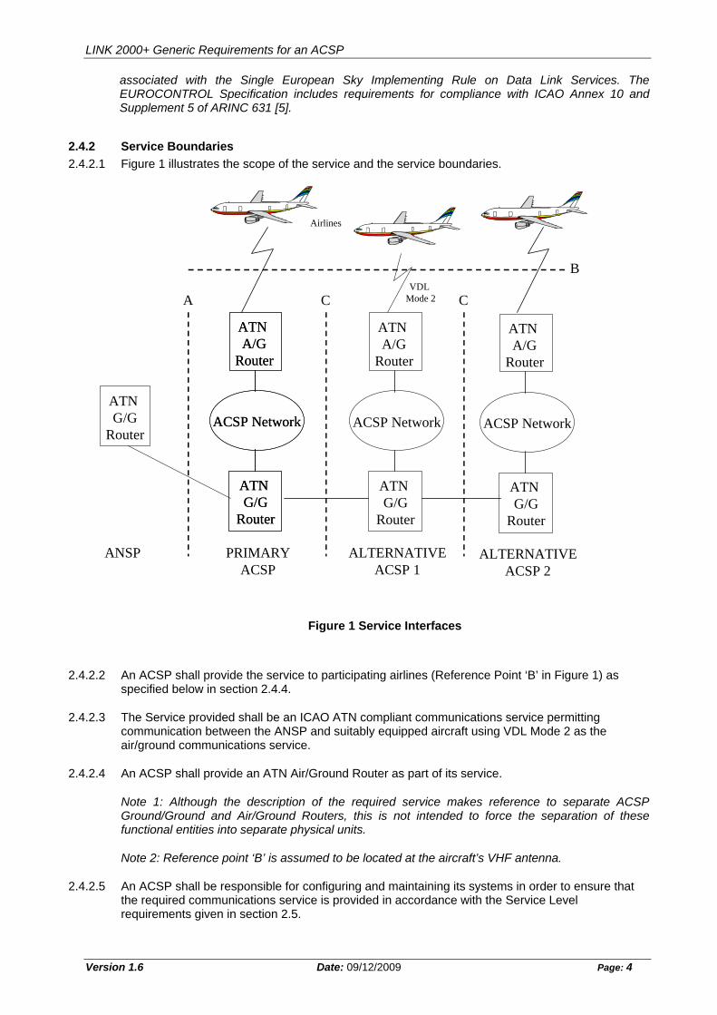
2.4.2.1 Figure 1 illustrates the scope of the service and the service boundaries.
Figure 1 Service Interfaces
ATN G/G
RouterACSP Network
Airlines
ATN A/G
Router
VDL Mode 2A
B
ATN G/G
Router
C
ACSP Network
ATN A/G
Router
ATN G/G
Router
ACSP Network
ATN A/G
Router
ATN G/G
Router
ANSP PRIMARYACSP
ALTERNATIVEACSP 1
ACSP Network
ATN A/G
Router
ATN G/G
Router
ALTERNATIVEACSP 2
C
2.4.2.2 An ACSP shall provide the service to participating airlines (Reference Point ‘B’ in Figure 1) as specified below in section 2.4.4.
2.4.2.3 The Service provided shall be an ICAO ATN compliant communications service permitting communication between the ANSP and suitably equipped aircraft using VDL Mode 2 as the air/ground communications service.
2.4.2.4 An ACSP shall provide an ATN Air/Ground Router as part of its service.
Note 1: Although the description of the required service makes reference to separate ACSP Ground/Ground and Air/Ground Routers, this is not intended to force the separation of these functional entities into separate physical units.
Note 2: Reference point ‘B’ is assumed to be located at the aircraft’s VHF antenna.
2.4.2.5 An ACSP shall be responsible for configuring and maintaining its systems in order to ensure that the required communications service is provided in accordance with the Service Level requirements given in section 2.5.
Version 1.6 Date: 09/12/2009 Page: 4
LINK 2000+ Generic Requirements for an ACSP
Version 1.6 Date: 09/12/2009 Page: 5
2.4.3 Reference Point ‘A’ Connection to ANSP
2.4.3.1 The service interface at Reference Point ‘A’ shall comply with the requirements of the ANSP Specified Connection to the Primary ACSP.
2.4.4 Reference Point ‘B’ Service Provision to Participating Aircraft
2.4.4.1 Any ACSP providing ATN/VDL2 service to participating aircraft under the jurisdiction of a given ANSP shall provide an interface at Reference Point ‘B’ in accordance with the following requirements.
2.4.4.2 The VDL Mode 2 Service provided shall be compliant with ARINC Specification 631 “VHF Digital Link Implementation Provisions” [5]. The ACSP shall support all functionality specified by ARINC 631 [5] PICS as Mandatory for a Ground provider, and shall not implement functionality prohibited by these PICS.
2.4.4.3 The ACSP shall support VDL Mode 2 operation on the number of frequencies necessary to ensure that the Service Level Requirements specified by Section 2.5 are maintained, subject to the allocation of VHF frequencies to VDL Mode 2 by the appropriate regulatory authorities.
Note: EUROCONTROL simulations indicate that at least three frequencies will be required to support VDL Mode 2 operation following the LINK 2000+ Mandate.
2.4.4.4 The ACSP shall implement the Autotune procedure specified in ARINC 631 [5] to maintain the Service Level Requirements of Section 2.5 for communication with airborne aircraft, whenever this cannot be achieved on a single frequency. When so required, the ACSP shall be capable of sending an Autotune command in an uplinked Ground Requested Air Initiated Handoff command, as well as in the uplink response to both a Link Establishment request or Air Initiated Handoff request.
2.4.4.5 The ACSP shall implement the Autotune procedures in advance of the preceding requirements, if required by the ANSP or appropriate regulatory authority.
Note: The ANSP may require earlier implementation of Autotune, for example, to reduce the risk of disruption to the VDL service arising from a rapid growth in traffic, that would occur if Autotune was not implemented in sufficient time. Autotune may also be required by frequency regulatory authorities to enforce efficient use of the available spectrum.
2.4.4.6 Subject to the availability of appropriate frequencies, the ACSP may also support dedicated ground frequencies, by means of the Frequency Support List, in accordance with ARINC 631 [5].
2.4.4.7 When multi-frequency operation is in use, the ACSP shall support the Frequency Recovery procedure wherever dedicated ground frequencies are not in use, by inclusion of en-route frequencies in a Frequency Support List, in accordance with ARINC 631 [5].
2.4.4.8 When multi-frequency operation is in use, the ACSP shall take all practicable measures to avoid degradation of VDL Mode 2 performance and/or capacity arising from co-site effects between VDL Ground Stations operating on different frequencies.
2.4.4.9 When multi-frequency operation is in use, the ACSP shall implement a frequency management strategy to ensure that continuous VDL connectivity is maintained when an aircraft leaves the coverage of its current frequency while remaining in the ACSP’s CSC coverage.
Note: In the event that an aircraft loses VDL connectivity due to flying out of coverage of its current frequency, the aircraft will perform Frequency Recovery by reference to an airborne FSL, or else will return to the CSC. Either of these actions will generally lead to an interruption in VDL connectivity. If the aircraft reverts to the CSC, restoration of connectivity will be delayed due to the time taken to acquire the PECT. The ACSP is required to avoid any such interruption, for example by autotuning the aircraft to another frequency before loss of connectivity occurs.
LINK 2000+ Generic Requirements for an ACSP
Version 1.6 Date: 09/12/2009 Page: 6
2.4.4.10 The VDL Mode 2 Service shall provide access to an ICAO ATN compliant communications service provided by the ACSP via an ACSP operated Air/Ground Router in accordance with the requirements of the EUROCONTROL Specification [2].
2.4.4.11 The service offered by the ACSP’s ATN Ground/Ground Router shall be compliant with ICAO ATN standards for a Class 4 Router in accordance with the requirements of the EUROCONTROL Specification [2].
2.4.4.12 The ACSP’s ATN Ground/Ground Router should implement the agreed resolution of PDR M2110003 (“IDRP Connection Recovery Problem”).
Note: The above PDR is mandatory for Aircraft and Air/Ground Routers.
2.4.4.13 The ACSP shall propagate IDRP routes to aircraft over the air-ground link using the generic prefixes ‘All AINSC’ fixed (47002701) and ‘All ATSC’ fixed (47002781), with route aggregation applied in both cases.
Note: The above requirement is not intended to prohibit temporary advertisement of non-aggregated routes for testing or troubleshooting purposes, provided that any such temporary condition avoids any significant effect on the performance of the operational network.
2.4.4.14 It is recommended that routes using the generic prefixes ‘All AINSC’ and ‘All ATSC’ should be statically configured in the ACSP’s Air/Ground router(s), to avoid the reduction process and ensure that only one advertisement of the routes occurs after IDRP connectivity has been established between air and ground.
2.4.4.15 The ACSP’s Air/Ground router(s) shall never propagate to an aircraft (AINSC or ATSC mobile) any route prefixes received from an aircraft in IDRP UPDATE PDUs.
Note: This requirement is aimed at ensuring robustness of the ATN Routing environment. It prevents erroneous propagation of both ground routes (i.e. with ground route in the NLRI and airborne RDI in the RD Path attributes) and airborne routes (i.e. with airborne route in the NLRI and airborne RDI in the RD Path attributes).
2.4.4.16 The ACSP’s Air/Ground router(s) shall never propagate to a ground adjacency (AINSC or ATSC fixed) any route prefixes received from an aircraft in IDRP UPDATE PDUs, except for those carrying the aircraft’s own RDI route prefix.
Note: This requirement is also aimed at ensuring robustness of the ATN Routing environment. It prevents erroneous propagation of both ground routes (i.e. with ground route in the NLRI - airborne in the RD Path attributes), and airborne routes unrelated to the connected aircraft RDI (i.e. with a different RDI prefix in the NLRI and RD PATH attributes).
2.4.4.17 The ACSP’s VDL Mode 2 Service and ATN Air/Ground Router shall provide a communications path between participating aircraft and the ANSP’s ATN Ground/Ground Router. The ACSP’s ATN Air/Ground Router(s) shall advertise to each aircraft, using IDRP, a route capable of reaching the ANSP’s Routing Domain.
2.4.4.18 The ACSP’s Air/Ground Router(s) shall provide a communications path between participating aircraft and the ATN Ground/Ground Routers of all neighbouring ANSPs nominated by the contracting ANSP. The ACSP’s ATN Air/Ground Router(s) shall advertise to each aircraft, using IDRP, a route capable of reaching the nominated ANSP Routing Domains. In addition, IDRP routes to all participating aircraft shall be advertised to the nominated neighbouring ANSPs. The end-to-end communication service between participating aircraft and the nominated neighbouring ANSP shall satisfy the same Service Level Requirements as for the contracting ANSP, as specified by Section 2.5.
Note 1: The above requirements are specified to allow transfer of communications to take place by means of the ACM service specified by the EUROCONTROL Specification [2].
LINK 2000+ Generic Requirements for an ACSP
Version 1.6 Date: 09/12/2009 Page: 7
Note 2: It is anticipated that connectivity with neighbouring ANSPs will be supported either directly by the Primary ACSP or else via an interconnection with one or more Alternative ACSPs. However, other solutions are not excluded.
2.4.4.19 The ACSP shall undertake to implement a solution, mutually agreed with the ANSP (either by institutional or technical means), to ensure that aircraft of non-AOC Operators can establish ATN connectivity, and maintain that connectivity when crossing an ANSP boundary that also involves a change of Primary ACSP.
Note: The LINK 2000+ Mandate will require Non-AOC Operators to equip with LINK 2000+ avionics. Such aircraft can be expected to appear in LINK 2000+ airspace from 2011.
2.4.4.20 If the ACSP operates more than one A/G Router, then following a VDL handoff between VGSs connected to different A/G Routers, the ACSP shall take measures to minimize the time during which an obsolete air-ground IDRP route is maintained via an A/G Router through which an aircraft is no longer reachable.
Note: When an aircraft performs a handoff from one VGS to another, the old link is maintained for the value of TG5, with a default value of 60s on the ground. If the new VGS is connected to a different A/G router, then in the worst case, an obsolete IDRP route via the old A/G Router could be advertised to adjacent G/G Routers during this period. If this route has equal merit to the IDRP route via the new A/G Router, then uplink traffic may continue to be routed via the old A/G Router. Since the old link may no longer be functional (the default value of TG5 on the aircraft is only 20s) this is likely to lead to undesirable delays and/or TP4 re-transmissions.
2.4.5 Reference Point ‘C’ ACSP Inter-Connection
2.4.5.1 The service interface at Reference Point ‘C’ will be subject to commercial and technical agreement between the two applicable ACSPs.
2.4.5.2 The Primary ACSP shall:
a) shall implement a technical means to allow Alternative ACSPs to interconnect with it, so as to provide a communications path to the ANSP
b) shall use its best efforts to facilitate the establishment of interconnections to Alternative ACSPs with which the ANSP has established agreements
c) shall not take any action which may obstruct the interconnection of Alternative ACSPs.
2.4.5.3 Interconnected ACSPs shall establish Service Level Agreements and Operating Procedures between them to ensure that overall service level requirements of section 2.5 are satisfied when the end-to-end path traverses the network of more than one ACSP.
2.4.5.4 An ACSP providing an interconnection at Reference Point ‘C’ shall design and maintain their system so as to route communication traffic bi-directionally via that interface without imposition of any deficit in performance or quality of service compared to communication traffic to/from its own network, except when such a deficit arises from external factors outside the ACSP’s control.
2.5 Service Level Requirements
2.5.1 The level of service provided shall conform to the applicable parts of the EUROCONTROL Specification [2], and to the specific requirements listed below.
2.5.2 Capacity
2.5.2.1 The service provided shall be capable of maintaining the service level requirements while carrying the minimum number of uplink and downlink application level messages (inc. LACK) specified by the ANSP per aircraft per unit of time in support of the ATC Data link Service.
LINK 2000+ Generic Requirements for an ACSP
Version 1.6 Date: 09/12/2009 Page: 8
Note: A requirement of 60 uplink and downlink application messages per flight hour is consistent with the Link 2000+ CPDLC message load assumed for the conduct VDL Mode 2 capacity simulations [3].
2.5.2.2 The Primary ACSP shall be capable of supporting the number of flights simultaneously logged-on to the ATC Data Link Service within the Service Volume, as specified by the ANSP.
Note 1: The Primary ACSP is required to make ATC Data link Services accessible to aircraft which are not customers of the ACSP’s AOC service.
Note 2: It is the ACSP’s responsibility to ensure that its service has sufficient capacity to meet these requirements, for all the aircraft customers to which it offers a service, and irrespective of the level of demand for AOC services.
2.5.3 Performance
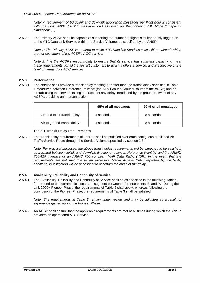
2.5.3.1 The service shall provide a transit delay meeting or better than the transit delay specified in Table 1 measured between Reference Point ‘A’ (the ATN Ground/Ground Router of the ANSP) and an aircraft using the service, taking into account any delay introduced by the ground network of any ACSPs providing an interconnection.
95% of all messages 99 % of all messages
Ground to air transit delay 4 seconds 8 seconds
Air to ground transit delay 4 seconds 8 seconds
Table 1 Transit Delay Requirements
2.5.3.2 The transit delay requirements of Table 1 shall be satisfied over each contiguous published Air Traffic Service Route through the Service Volume specified by section 2.3.
Note: For practical purposes, the above transit delay requirements will be expected to be satisfied, aggregated between uplink and downlink directions, between Reference Point ‘A’ and the ARINC 750/429 interface of an ARINC 750 compliant VHF Data Radio (VDR). In the event that the requirements are not met due to an excessive Media Access Delay reported by the VDR, additional investigation will be necessary to ascertain the origin of the delay.
2.5.4 Availability, Reliability and Continuity of Service
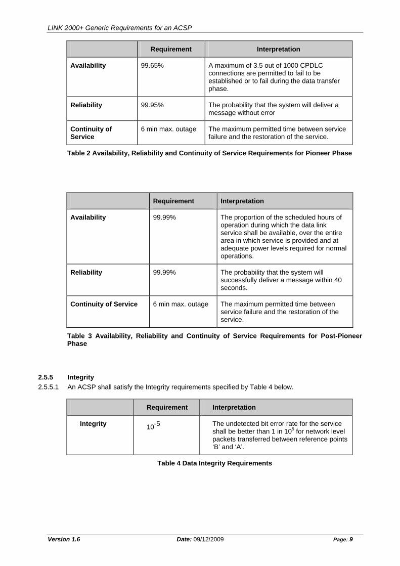
2.5.4.1 The Availability, Reliability and Continuity of Service shall be as specified in the following Tables for the end-to-end communications path segment between reference points ‘B’ and ‘A’. During the Link 2000+ Pioneer Phase, the requirements of Table 2 shall apply, whereas following the conclusion of the Pioneer Phase, the requirements of Table 3 shall be satisfied.
Note: The requirements in Table 3 remain under review and may be adjusted as a result of experience gained during the Pioneer Phase.
2.5.4.2 An ACSP shall ensure that the applicable requirements are met at all times during which the ANSP provides an operational ATC Service.
LINK 2000+ Generic Requirements for an ACSP
Version 1.6 Date: 09/12/2009 Page: 9
Requirement Interpretation
Availability 99.65% A maximum of 3.5 out of 1000 CPDLC connections are permitted to fail to be established or to fail during the data transfer phase.
Reliability 99.95% The probability that the system will deliver a message without error
Continuity of Service
6 min max. outage The maximum permitted time between service failure and the restoration of the service.
Table 2 Availability, Reliability and Continuity of Service Requirements for Pioneer Phase
Requirement Interpretation
Availability 99.99% The proportion of the scheduled hours of operation during which the data link service shall be available, over the entire area in which service is provided and at adequate power levels required for normal operations.
Reliability 99.99% The probability that the system will successfully deliver a message within 40 seconds.
Continuity of Service 6 min max. outage The maximum permitted time between service failure and the restoration of the service.
Table 3 Availability, Reliability and Continuity of Service Requirements for Post-Pioneer Phase
2.5.5 Integrity
2.5.5.1 An ACSP shall satisfy the Integrity requirements specified by Table 4 below.
Requirement Interpretation
Integrity 10-5 The undetected bit error rate for the service shall be better than 1 in 105 for network level packets transferred between reference points ‘B’ and ‘A’.
Table 4 Data Integrity Requirements
LINK 2000+ Generic Requirements for an ACSP
Version 1.6 Date: 09/12/2009 Page: 10
2.5.6 Priority
2.5.6.1 An ACSP’s ATN Routers shall enforce CLNP packet priority.
2.5.6.2 Higher priority packets shall be forwarded before lower priority packets in the same outgoing queue.
2.5.6.3 If an ATN Router discards packets due to congestion then lower priority packets shall be discarded before higher priority packets are discarded.
2.5.6.4 The VDL Mode 2 Ground Station should uplink any ATC messages queued for uplink before uplinking other messages.
Note: This desirable requirement is intended to differentiate between ATN and e.g. AOA messages. It is not intended to require that the VGS references or even has access to CLNP priority.
2.5.7 Safety and Security
2.5.7.1 An ACSP shall ensure that only authorised users have access to their part of the Aeronautical Telecommunication Network.
2.5.7.2 The ANSP shall determine who is an “authorised user”.
Note 1: The term “authorised users” embraces both ground systems and participating aircraft.
Note 2: A potential threat exists from unauthorised access to the ATN permitting a ground user to masquerade as a valid airborne user.
2.5.7.3 In consultation with the ANSP, an ACSP shall establish procedures and rules for users that want to use the ATN/VDL Mode-2 network for test purposes, which have potential to impact on the operational service provided by the ANSP.
2.5.7.4 An ACSP shall ensure that test users do not interfere with the operational network users.
2.5.8 Maintenance
2.5.8.1 An ACSP shall monitor and maintain the communications service and the systems used to provide the service in order to ensure that the specified service levels are achieved.
2.5.8.2 An ACSP shall undertake to correct in a timely fashion any significant non-compliance with applicable Standards (including any subsidiary normative standard) discovered during provision of the Service.
2.6 Performance Monitoring and Network Management
2.6.1 An ACSP shall monitor all system functions within the scope of the service level requirements.
2.6.2 An ACSP shall identify to the ANSP all recording and data logging mechanisms currently supported by their ATN/VDL Mode 2 network.
2.6.3 In addition:
a) The ACSP shall nominate a Manager who is personally accountable for the delivery and maintenance of the ATN/VDL service in accordance with the requirements of this document.
b) An ACSP shall develop and agree with the ANSP or its nominated Agent prior to commencing the service a manual of fault reporting procedures and practices and escalation procedures to define, communicate and remedy faults and deficiencies.
LINK 2000+ Generic Requirements for an ACSP
Version 1.6 Date: 09/12/2009 Page: 11
c) An ACSP shall install data recording and logging functions at critical points of observation in the network to support fault and performance analysis. Logging of network activity shall be performed against UTC time to facilitate correlation with other sources of information. The ACSP shall agree with the ANSP or its nominated Agent which points of observation will be subject to logging, but as a minimum, it is expected that they will include the VGS, the A/G Router, and where implemented, Reference Point ‘C’.
d) An ACSP shall provide upon user request (i.e. the ANSP or its nominated Agent and Airline customer) all necessary technical assistance, normally within one working day, including (but not limited to) provision of logs of ATN and VDL traffic against UTC time, to facilitate technical investigations into performance of the Service.
e) An ACSP providing an interconnection with an Alternative ACSP shall co-operate fully with the ANSP or its nominated Agent and interconnected ACSPs to achieve a timely resolution of any technical problems identified in the service level of data traffic carried through the interconnection.
f) An ACSP shall develop and agree with the ANSP or its nominated Agent a problem reporting procedure to notify the users (i.e. the ANSP and Airline customer) of detected problems, including any degradation in the service, the impact on the service and the progress of the solution. The ACSP shall respond to reasonable requests from the ANSP to minimise the operational impact of any problem or degradation.
g) An ACSP shall provide a clearly identified “Point of Contact” that can be contacted whenever the ANSP or its nominated Agent experiences technical problems with the services provided by the ACSP.
h) An ACSP shall analyse and attempt to resolve the reported problems and, if appropriate, take the required corrective actions needed to maintain the service.
i) The identified “Point of Contact” shall be available at all times during which the ANSP is providing an operational ATC Service
j) An ACSP shall provide a monthly Performance Level Report showing the service level achieved for the service provided. The required content of the Report will be established by the ANSP or its nominated Agent; it should contain as much as practicable the information specified in Annex A.
k) This report shall be sent to the ANSP or its nominated Agent electronically within 10 (ten) calendar days from the end of the subject month.
l) An ACSP shall give at least 1 day advanced notice of scheduled network maintenance activities and the type of activity. The ACSP shall highlight any degradation in service expected from the activity, and shall respond to reasonable requests from the ANSP or its nominated Agent to minimise the operational impact of such degradation.
m) An ACSP shall provide to the ANSP or its nominated Agent not less than 14 days notice of any changes to the architecture, configuration or software versions of any component of the ATN/VDL network involved in provision of the Service. The ACSP shall highlight any degradation in service expected from the activity, and shall respond to reasonable requests from the ANSP or its nominated Agent to minimise the operational impact of such degradation.
LINK 2000+ Generic Requirements for an ACSP
Version 1.6 Date: 09/12/2009 Page: 12
3. EVALUATION OF THE COMMUNICATION SERVICE
3.1 Evaluation Process
3.1.1 Prior to offering any operational ATN VDL Mode 2 Service, an ACSP shall complete a process of evaluation to the satisfaction of the ANSP. The evaluation process shall consist of the following steps:
a) Delivery of documentary evidence to the ANSP
b) Completion of laboratory acceptance tests
c) Completion of flight tests demonstrating fitness-for-purpose
3.2 Delivery of Documentary Evidence
3.2.1 The ACSP shall deliver to the ANSP documentation providing evidence of the ability of the ACSP’s ATN and VDL Mode 2 system to satisfy the end-to-end functional and service level requirements specified by this document. The documentation delivered shall include (but not be limited to) the items listed in Annex B.
3.2.2 The ANSP will review this documentation to verify that it includes the necessary evidence of conformance with the end-to-end requirements.
3.2.3 The ACSP shall provide any additional evidence of conformance with requirements specified by this document reasonably required by the ANSP.
3.3 Laboratory Acceptance Tests
3.3.1 The ACSP shall perform a series of Laboratory Acceptance Tests to demonstrate end-to-end ATN connectivity with the ANSPs systems, together with performance and robustness of the VDL Mode 2 Service. The expected configuration and scope of these Acceptance Tests is described in Annex C.
3.3.2 Prior to conduct of the Acceptance Tests, the ACSP shall prepare an Acceptance Test Specification detailing the configuration and conduct of all tests to be performed. The Acceptance Test Specification shall include (but not be limited to) the tests described in Annex C.
3.3.3 The Acceptance Test Specification shall be subject to review by the ANSP. Any additional tests reasonably required by the ANSP to demonstrate interoperability with the ANSP’s system shall be included.
3.3.4 The ANSP may require its representatives to witness the conduct of Acceptance Tests by the ACSP.
3.3.5 Following completion of the Acceptance Tests, the ACSP shall deliver an Acceptance Test Report to the ANSP, detailing all results. The ACSP shall also make available all logs and records collected during the conduct of the tests.
3.3.6 The ANSP may elect, at its sole discretion, to accept documentary evidence of satisfactory completion of certain Acceptance Tests by the ACSP on a previous occasion, without requiring further conduct of such Tests.
Note: Specific tests described in Annex C are intended to demonstrate functionality of the interface to the ANSP, and such tests will normally be required by each ANSP.
LINK 2000+ Generic Requirements for an ACSP
Version 1.6 Date: 09/12/2009 Page: 13
3.4 Flight Tests
3.4.1 The ACSP shall co-operate with the ANSP in arranging the conduct of flight tests to demonstrate that the ATN/VDL Mode 2 Service is fit for the intended purpose. The flight testing shall be performed over routes specified by the ANSP.
Note 1: Flight testing is intended to demonstrate that adequate coverage is provided by the ACSP’s VGSs along major ATS routes through airspace under the jurisdiction of the ANSP. In addition it seeks to give confidence that functionality such as VDL handoffs are robust under real world conditions. The ANSP will take into account the size and architecture of the airspace when specifying the duration and routes over which flight trials are required.
Note 2: The arrangements for flight testing, including commercial considerations, will be the subject of agreement between the ANSP and the ACSP. Either a dedicated flight test or else conduct of tests with an airline customer’s aircraft on revenue earning flights will be considered suitable to meet the requirements.
3.4.2 Throughout every flight test, a continuous exchange of uplink and downlink CPDLC messages shall be maintained, at a nominal rate of not less than one message every 10 seconds in each direction.
Note: The requirement for a continuous exchange of CPDLC messages may be achieved by a ‘tuning test’ involving an uplink of an erroneous CPDLC message, soliciting a downlink CPDLC ERROR response, without involvement of the CDU or the aircrew.
3.4.3 Prior to conduct of the flight test, a Flight Test Specification shall be prepared detailing the configuration, and conduct of the proposed flight tests, including the aircraft and the routes to be flown. The Flight Test Specification shall be subject to review of the ANSP and all reasonable requests for change shall be incorporated.
3.4.4 The pass criteria for the flight tests shall be that while the aircraft remains in airspace within which the ACSP is required to provide coverage:
a) An IDRP adjacency shall be maintained with the aircraft
b) No interruption shall occur to the continuous exchange of CPDLC messages
c) No CPDLC message shall fail to be delivered
d) The Transit Delay requirements specified by this document shall be satisfied over each individual ATS route along which the test aircraft has flown.
3.4.5 Following completion of the Flight Tests, a Flight Test Report shall be prepared, detailing all results. The ACSP shall also make available all logs and records collected during the conduct of the tests.
3.4.6 The ANSP may elect, at its sole discretion, to accept documentary evidence of satisfactory completion of certain Flight Tests by the ACSP on a previous occasion, without requiring further conduct of such Tests.
4. OBSERVATION PERIOD OF OPERATIONAL SERVICE
4.1 Observation Process
4.1.1 Following successful completion of the evaluation process in accordance with Section 3 above, the ACSP will be permitted to offer an operational service for a limited period constituting the Observation Period. The Observation Period shall last for a period specified by the ANSP.
Note: Typically the Observation Period will last for a period of 3 months.
LINK 2000+ Generic Requirements for an ACSP
Version 1.6 Date: 09/12/2009 Page: 14
4.1.2 During the observation period, the ANSP will monitor the functionality and performance of the Service provided by the ACSP, and also the compliance of the ACSP with the performance monitoring and network management requirements (Section 2.6 refers).
4.1.3 The ANSP may impose certain constraints on the service to be offered during the observation period (e.g. limits to the airlines permitted to use the Service) in order to facilitate the monitoring of the service.
4.1.4 Any shortcomings detected in the Service during the observation period will be addressed by means of the procedures outlined in Section 2.6 of this document.
4.1.5 Once all outstanding issues have been resolved to the satisfaction of the ANSP, the ACSP’s ATN/VDL Mode 2 Service will be declared fully operational, and any remaining constraints will be withdrawn.
LINK 2000+ Generic Requirements for an ACSP
Version 1.6 Date: 09/12/2009 Page: 15
ANNEX A – CONTENT OF ACSP’s MONTHLY PERFORMANCE REPORT
A.1 Overall Report on Quality of Service
Availability of VGSs ( percentage, failure)
Availability of AGR routers (percentage, failure)
Availability of Network Infrastructure
Explanations of failures (if any).
A.2 Statistics
A.2.1 Statistics on Aircraft
Number of aircraft connected and handled
Graphical representation of the trend for aircraft.
A.2.2 Statistics on VGSs
A.2.2.1 At AVLC layer
Per VGS, number of Link Establishments (Received, Rejected, Accepted)
Per VGS, number of Handoffs (Received, Rejected, Accepted)
Per VGS, statistics per frame type exchanged with aircraft : INFO (sent, received) - SREJ (sent, received) - FRMR (sent, received)
Graphical representation of the trend for AVLC frames (INFO, SREJ, FRMR).
A.2.2.2 At 8208 layer
Per VGS, number of 8208 PDUs sent to/received from aircraft
Per VGS, number of 8208 PDUs sent to/received from AGR routers
Graphical representation of the trend for 8208 PDUs.
A.2.3 Statistics on AGRs
Per AGR, number of 8208 PDUs sent to/received from VGSs
Graphical representation of the trend for 8208 PDUs
Per AGR, number of CLNP DT and ER NPDUs (sent,received)
Graphical representation of the trend for CLNP DT and ER NPDUs .
A.2.5 Report of executed and planned changes to the network
LINK 2000+ Generic Requirements for an ACSP
Version 1.6 Date: 09/12/2009 Page: 16
ANNEX B – DOCUMENTATION REQUIREMENTS
B.1 Introduction
The ACSP is required to provide the ANSP with documentary evidence that the ACSP’s ATN and VDL Mode 2 systems are capable of satisfying the end-to-end functional and service level requirements specified by this document.
Where necessary, the ACSP will be expected to make an appropriate allocation of service level requirements (e.g. performance, availability, reliability and continuity) between the different components of the system, and to provide evidence that each component is capable of meeting the relevant allocation.
B.1.1 Functional Requirements
CLNP and IDRP PICS for both ACSP Air/Ground and ground routers
X.25 PICS for the ground router
Reference Documentation of the ACSP Air/Ground Router
Reference Documentation of the ACSP Ground Router
VDL Mode 2 PICS for the VGS
Reference Documentation of the VGS
The above documentations shall specify the implemented values of all configurable timers, counters and other parameters defined by ICAO and/or other applicable normative standards.
B.1.2 Capacity
A report showing the ACSP has performed testing while simulating establishment of multiple aircraft mobile links and IDRP adjacencies on their Air/Ground router, demonstrating compliance with the Capacity Requirements stated in this document.
A report showing the ACSP has performed testing with multiple simulated aircraft IDRP routes received on their ground router, including a repetitive exercise consisting of adding IDRP routes, checking IDRP routes prefixes and removing IDRP routes, demonstrating compliance with the Capacity Requirements stated in this document.
A report showing the ACSP has performed testing while simulating establishment of multiple mobile links, traffic exchanges and clear of connectivity on one VGS, demonstrating compliance with the Capacity Requirements stated in this document.
B.1.3 Performance
A report on performance tests done by the ACSP on their Air/Ground ATN Router, demonstrating consistency with the Performance Requirements stated in this document.
A report on performance tests done by the ACSP on their Ground ATN Router, demonstrating consistency with the Performance Requirements stated in this document.
A report on performance tests performed by the ACSP on their VGSs, demonstrating consistency with the Performance Requirements specified by this document.
LINK 2000+ Generic Requirements for an ACSP
Version 1.6 Date: 09/12/2009 Page: 17
B.1.4 Priority
A functional description of the ACSP’s ATN priority management mechanism.
A/G and Ground Routers logs from simulations performed in the ACSP’s Laboratory illustrating the action of the priority management mechanism.
A functional description of the implementation of priority management within the ACSP’s VDL Mode 2 system.
VGS traces illustrating the action of priority management with both ATC and AOC traffic involved.
B.1.5 Safety and Security Policy
IDRP policy rules put in place on both Air/Ground and Ground routers.
RIF Known BIS attributes defined by the ACSP in the Air/Ground router configuration.
Mechanisms / rules put in place at VSGs to satisfy safety and security requirements.
B.1.6 ATN Availability, Reliability and Continuity
An overall description of the ACSP’s technical measures to satisfy the Availability, Reliability and Continuity requirements.
Results on Endurance Tests performed by the ACSP in their laboratory on Air/Ground and Ground ATN systems, supplemented by operational experience where possible.
A description of redundancy systems/mechanisms which are put in place for both Air/Ground and Ground ATN systems.
A description of the recovery procedure for both Air/Ground and Ground ATN systems in case of software and hardware failures.
Results on Endurance Tests performed by the ACSP in their laboratory on VDL Mode 2 VGSs and other components, supplemented by operational experience where possible.
A description of redundancy systems/mechanisms which are put in place for VDL Mode 2 VGS sand other components.
A description of the recovery procedure for VDL Mode 2 VGSs and other components in case of software and hardware failures.
B.1.7 VDL Coverage
Expected geographical coverage from the ACSP’s individual VDL Ground Stations providing the service within the volume of airspace in which the ANSP requires ATN/VDL Service, taking into account line-of-sight considerations and ground topography. It is expected that the coverage will be given at a range of altitudes, including (but not limited to) the minimum and maximum altitudes of the relevant airspace.
LINK 2000+ Generic Requirements for an ACSP
ANNEX C – LABORATORY ACCEPTANCE TEST PROCEDURES
C.1 Configuration
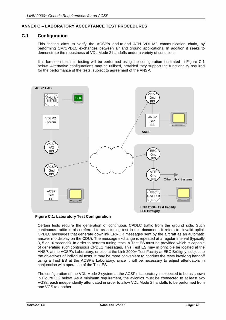
This testing aims to verify the ACSP’s end-to-end ATN VDL-M2 communication chain, by performing CM/CPDLC exchanges between air and ground applications. In addition it seeks to demonstrate the robustness of VDL Mode 2 handoffs under a variety of conditions.
It is foreseen that this testing will be performed using the configuration illustrated in Figure C.1 below. Alternative configurations may be utilised, provided they support the functionality required for the performance of the tests, subject to agreement of the ANSP.
ACSP LAB
EEC, Bretigny
eecg
CDU
a ardman_g
Other LINK systems
atifr
A
air lab
acsp G
VDL - M2
system
UAC Maastricht
maases
maasg
G Tool
ACSP LAB
CDU
X25X25
VDLM2System
Avionic
MADAPMADAPANSPGndES
BIS/ES
ACSPA/GBIS
ACSPGndBIS
ACSPTestES
MADAPMADAP
ANSPGndBIS
ANSP
EECGndBIS
ATIFGndBIS Other LINK Systems
LINK 2000+ Test FacilityEEC Brétigny
EECGnd Test
ES
Figure C.1: Laboratory Test Configuration
Certain tests require the generation of continuous CPDLC traffic from the ground side. Such continuous traffic is also referred to as a tuning test in this document. It refers to invalid uplink CPDLC messages that generate downlink ERROR messages sent by the aircraft as an automatic answer (no display on the CDU). The message exchange is repeated at a regular interval (typically 3, 5 or 10 seconds). In order to perform tuning tests, a Test ES must be provided which is capable of generating such continuous CPDLC messages. This Test ES may in principle be located at the ANSP, at the ACSP’s Laboratory, or else at the Link 2000+ Test Facility at EEC Brétigny, subject to the objectives of individual tests. It may be more convenient to conduct the tests involving handoff using a Test ES at the ACSP’s Laboratory, since it will be necessary to adjust attenuators in conjunction with operation of the Test ES.
The configuration of the VDL Mode 2 system at the ACSP’s Laboratory is expected to be as shown in Figure C.2 below. As a minimum requirement, the avionics must be connected to at least two VGSs, each independently attenuated in order to allow VDL Mode 2 handoffs to be performed from one VGS to another.
Version 1.6 Date: 09/12/2009 Page: 18
LINK 2000+ Generic Requirements for an ACSP
VGS 1
VGS 2
MONITORINGTOOL
= RF
= Fixed RF attenuator
= Variable RFattenuator
= Co-axial cable
VDR
VDR
VDR
VDRC
MU
VGS 1
VGS 2
ATT 1ATT 1ATT 1ATT 1
MONITORINGTOOL
= RF Splitter/Combiner
= Fixed RF attenuator
= Variable RFattenuator
= Co-axial cable
VDR
VDR
VDR
VDR
AVIONICS TEST RIG
CM
U
ATT 2ATT 2ATT 2ATT 2
Figure C.2: VDL Mode 2 System at ACSP’s Laboratory
C.2 Test Descriptions
C.2.1 ACSP Air/Ground System Connectivity
Test Reference TST_LAB_AGS_CONNECT
Objective This test aims at checking the connectivity events that occur on the ground side once the “Air/Ground ACSP system” is started up.
(The air side is not started yet)
Preamble ANSP ground router is up and running
Related Requirements
Functional Requirements
Configuration As in Section E.1. The ANSP BIS is located at the ANSP’s premises connected via the operational interface to the ACSP.
Description Power up the Air/Ground ACSP system
Once ground-ground IDRP adjacency is established between ANSP and ACSP ground routers, issue Echo Requests with Security (ATSC Class A, ATSC No Pref) from EEC ground router to ACSP ground router.
Observation Points Check connectivity is established between the ACSP Air/Ground system and ANSP ground router
Check IDRP connectivity is established between both ANSP and ACSP ground ATN routers
Check ACSP routes are propagated by the ACSP ground router
Version 1.6 Date: 09/12/2009 Page: 19
LINK 2000+ Generic Requirements for an ACSP
Version 1.6 Date: 09/12/2009 Page: 20
to the ANSP ground adjacency
Check that routes propagated by ANSP router are present on the ACSP system side.
Check that Echo replies are received as answers to the Echo Requests sent by ANSP ground router
PASS Criteria Ground/Ground IDRP adjacency established between ACSP and ANSP ground routers
Routing Domain prefix routes with security to the remote system available on both routers
Echo replies from ACSP ground router received at ANSP router
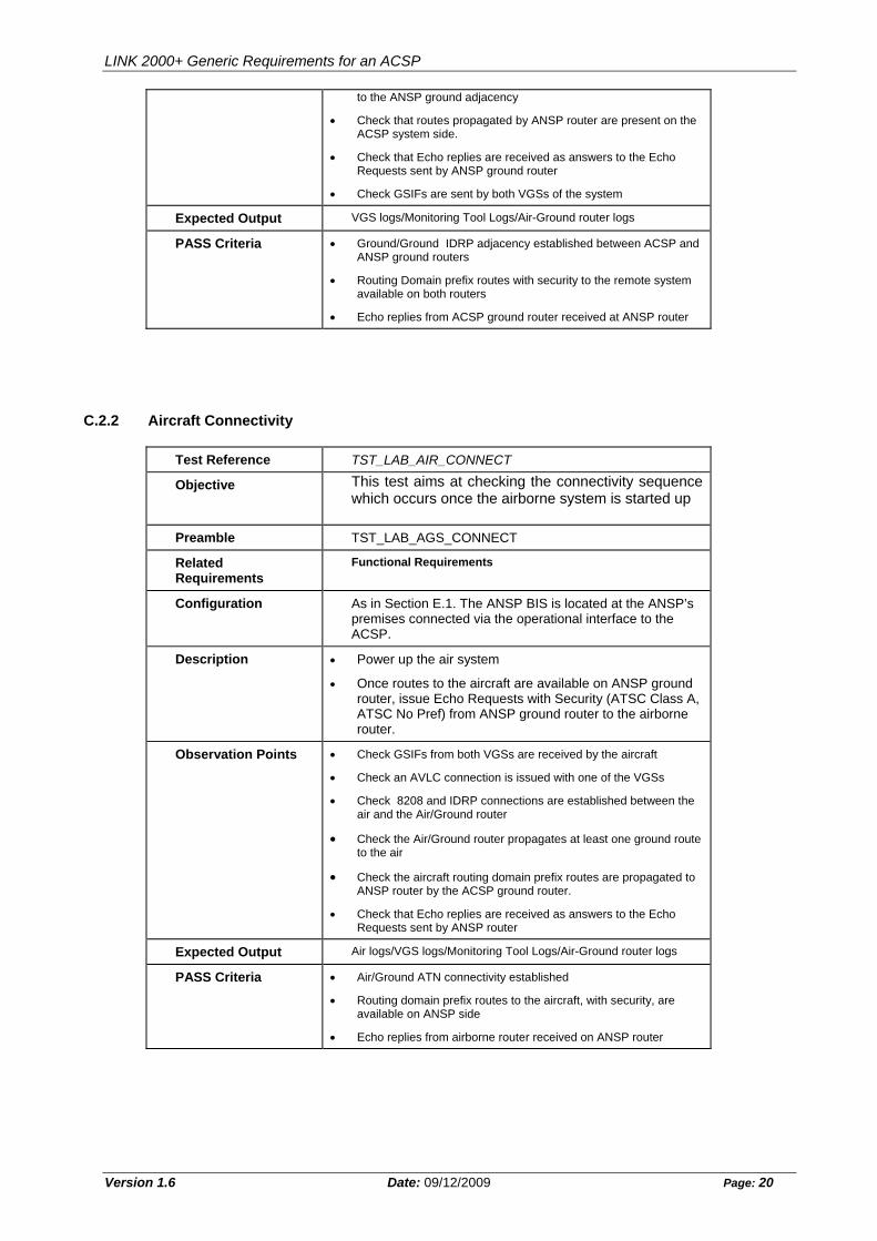
C.2.2 Aircraft Connectivity
Test Reference TST_LAB_AIR_CONNECT
Objective This test aims at checking the connectivity sequence which occurs once the airborne system is started up
Preamble TST_LAB_AGS_CONNECT
Related Requirements
Functional Requirements
Configuration As in Section E.1. The ANSP BIS is located at the ANSP’s premises connected via the operational interface to the ACSP.
Description Power up the air system
Once routes to the aircraft are available on ANSP ground router, issue Echo Requests with Security (ATSC Class A, ATSC No Pref) from ANSP ground router to the airborne router.
Observation Points Check GSIFs from both VGSs are received by the aircraft
Check an AVLC connection is issued with one of the VGSs
Check 8208 and IDRP connections are established between the air and the Air/Ground router
Check the Air/Ground router propagates at least one ground route to the air
Check the aircraft routing domain prefix routes are propagated to ANSP router by the ACSP ground router.
Check that Echo replies are received as answers to the Echo Requests sent by ANSP router
Expected Output Air logs/VGS logs/Monitoring Tool Logs/Air-Ground router logs
PASS Criteria Air/Ground ATN connectivity established
Routing domain prefix routes to the aircraft, with security, are available on ANSP side
Echo replies from airborne router received on ANSP router
LINK 2000+ Generic Requirements for an ACSP
Version 1.6 Date: 09/12/2009 Page: 21
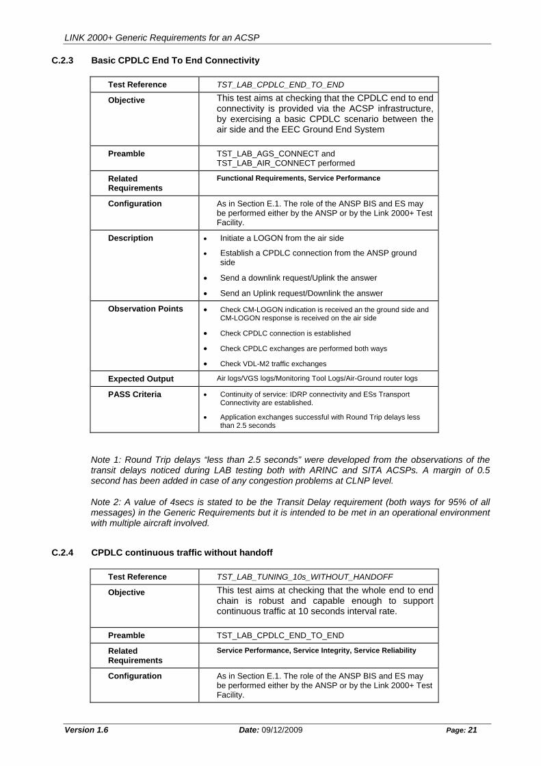
C.2.3 Basic CPDLC End To End Connectivity
Test Reference TST_LAB_CPDLC_END_TO_END
Objective This test aims at checking that the CPDLC end to end connectivity is provided via the ACSP infrastructure, by exercising a basic CPDLC scenario between the air side and the EEC Ground End System
Preamble TST_LAB_AGS_CONNECT and TST_LAB_AIR_CONNECT performed
Related Requirements
Functional Requirements, Service Performance
Configuration As in Section E.1. The role of the ANSP BIS and ES may be performed either by the ANSP or by the Link 2000+ Test Facility.
Description Initiate a LOGON from the air side
Establish a CPDLC connection from the ANSP ground side
Send a downlink request/Uplink the answer
Send an Uplink request/Downlink the answer
Observation Points Check CM-LOGON indication is received an the ground side and CM-LOGON response is received on the air side
Check CPDLC connection is established
Check CPDLC exchanges are performed both ways
Check VDL-M2 traffic exchanges
Expected Output Air logs/VGS logs/Monitoring Tool Logs/Air-Ground router logs
PASS Criteria Continuity of service: IDRP connectivity and ESs Transport Connectivity are established.
Application exchanges successful with Round Trip delays less than 2.5 seconds
Note 1: Round Trip delays “less than 2.5 seconds” were developed from the observations of the transit delays noticed during LAB testing both with ARINC and SITA ACSPs. A margin of 0.5 second has been added in case of any congestion problems at CLNP level.
Note 2: A value of 4secs is stated to be the Transit Delay requirement (both ways for 95% of all messages) in the Generic Requirements but it is intended to be met in an operational environment with multiple aircraft involved.
C.2.4 CPDLC continuous traffic without handoff
Test Reference TST_LAB_TUNING_10s_WITHOUT_HANDOFF
Objective This test aims at checking that the whole end to end chain is robust and capable enough to support continuous traffic at 10 seconds interval rate.
Preamble TST_LAB_CPDLC_END_TO_END
Related Requirements
Service Performance, Service Integrity, Service Reliability
Configuration As in Section E.1. The role of the ANSP BIS and ES may be performed either by the ANSP or by the Link 2000+ Test Facility.
LINK 2000+ Generic Requirements for an ACSP
Version 1.6 Date: 09/12/2009 Page: 22
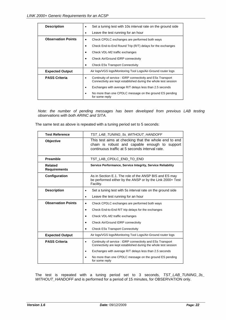
Description Set a tuning test with 10s interval rate on the ground side
Leave the test running for an hour
Observation Points Check CPDLC exchanges are performed both ways
Check End-to-End Round Trip (R/T) delays for the exchanges
Check VDL-M2 traffic exchanges
Check Air/Ground IDRP connectivity
Check ESs Transport Connectivity
Expected Output Air logs/VGS logs/Monitoring Tool Logs/Air-Ground router logs
PASS Criteria Continuity of service : IDRP connectivity and ESs Transport Connectivity are kept established during the whole test session
Exchanges with average R/T delays less than 2.5 seconds
No more than one CPDLC message on the ground ES pending for some reply
Note: the number of pending messages has been developed from previous LAB testing observations with both ARINC and SITA.
The same test as above is repeated with a tuning period set to 5 seconds:
Test Reference TST_LAB_TUNING_5s_WITHOUT_HANDOFF
Objective This test aims at checking that the whole end to end chain is robust and capable enough to support continuous traffic at 5 seconds interval rate.
Preamble TST_LAB_CPDLC_END_TO_END
Related Requirements
Service Performance, Service Integrity, Service Reliability
Configuration As in Section E.1. The role of the ANSP BIS and ES may be performed either by the ANSP or by the Link 2000+ Test Facility.
Description Set a tuning test with 5s interval rate on the ground side
Leave the test running for an hour
Observation Points Check CPDLC exchanges are performed both ways
Check End-to-End R/T trip delays for the exchanges
Check VDL-M2 traffic exchanges
Check Air/Ground IDRP connectivity
Check ESs Transport Connectivity
Expected Output Air logs/VGS logs/Monitoring Tool Logs/Air-Ground router logs
PASS Criteria Continuity of service : IDRP connectivity and ESs Transport Connectivity are kept established during the whole test session
Exchanges with average R/T delays less than 2.5 seconds
No more than one CPDLC message on the ground ES pending for some reply
The test is repeated with a tuning period set to 3 seconds, TST_LAB_TUNING_3s_ WITHOUT_HANDOFF and is performed for a period of 15 minutes, for OBSERVATION only.
LINK 2000+ Generic Requirements for an ACSP
Version 1.6 Date: 09/12/2009 Page: 23
C.2.5 Tuning tests with handoffs based on SQP dropping
Test Reference TST_LAB_TUNING_10s _HANDOFF_SQP
Objective This test aims at checking that the ACSP Air/Ground system is robust and capable enough to support continuous traffic at 10 seconds interval rate while handoffs between both VGSs of the Air/Ground system are exercised.
Preamble TST_LAB_CPDLC_END_TO_END,
Establishment of attenuators settings: set the attenuators of both VGSs to give a reported SQP of 2 at the CMU. For the VGS not currently connected, this can be achieved by monitoring the GSIF frames received by the CMU. This is referred to as the 'normal' setting.
Related Requirements
Functional Requirements, Service Performance, Service Integrity, Service Reliability
Configuration As in Section E.1. The role of the ANSP BIS and ES may be performed by the ACSP Laboratory.
Description Set a tuning test with 10s interval rate on the ground side
Handoff sequence:
Progressively reduce the setting of the attenuator for the VGS with a current AVLC connection to the CMU (ATT 1) in 1 dB steps. Wait for 20 seconds between each step.
Verify that handoff due to SQP dropping occurs
Wait 5 minutes
Return attenuator ATT 1 to the normal setting giving SQP 2
Wait 3 minutes
Progressively reduce the setting of the attenuator ATT 2 in 1 dB steps. Wait for 20 seconds between each step.
Verify that handoff due to SQP dropping occurs
Wait 5 minutes
Return attenuator ATT 2 to the normal setting giving SQP 2
Wait 3 minutes
Repeat the Handoff sequence 10 times
Observation points Check exchanges are performed both ways
Check VDL-M2 traffic exchanges
Check VDL8208 connectivity establishment/release on the Air/Ground router
Check Air/Ground IDRP Connectivity
Check ESs TP4 Connectivity
Expected Output Air logs/VGS logs/Monitoring Tool Logs/Air-Ground router logs
LINK 2000+ Generic Requirements for an ACSP
Version 1.6 Date: 09/12/2009 Page: 24
PASS Criteria Continuity of service : Air/Ground IDRP connectivity and ESs Transport Connectivity are kept established during the whole test session
Uplink messages are received on the air side
Downlink replies are received on the ground side
No more than three messages pending for some reply on the ground
The same test as above is repeated with a tuning period set to 5 seconds:
Test Reference TST_LAB_TUNING_5s _HANDOFF_SQP
Objective This test aims at checking that the ACSP Air/Ground system is robust and capable enough to support continuous traffic at 5 seconds interval rate while handoffs between both VGSs of the Air/Ground system are exercised.
Preamble TST_LAB_CPDLC_END_TO_END,
Establishment of attenuators settings: set the attenuators of both VGSs to give a reported SQP of 2 at the CMU. For the VGS not currently connected, this can be achieved by monitoring the GSIF frames received by the CMU. This is referred to as the 'normal' setting.
Related Requirements
Functional Requirements, Service Performance, Service Integrity, Service Reliability
Configuration As in Section E.1. The role of the ANSP BIS and ES may be performed by the ACSP Laboratory.
Description Set a tuning test with 5s interval rate on the ground side
Handoff sequence:
Progressively reduce the setting of the attenuator for the VGS with a current AVLC connection to the CMU (ATT 1) in 1 dB steps. Wait for 20 seconds between each step.
Verify that handoff due to SQP dropping occurs
Wait 5 minutes
Return attenuator ATT 1 to the normal setting giving SQP 2
Wait 3 minutes
Progressively reduce the setting of the attenuator ATT 2 in 1 dB steps. Wait for 20 seconds between each step.
Verify that handoff due to SQP dropping occurs
Wait 5 minutes
Return attenuator ATT 2 to the normal setting giving SQP 2
Wait 3 minutes
Repeat the Handoff sequence 10 times
LINK 2000+ Generic Requirements for an ACSP
Version 1.6 Date: 09/12/2009 Page: 25
Observation points Check exchanges are performed both ways
Check VDL-M2 traffic exchanges
Check VDL8208 connectivity establishment/release on the Air/Ground router
Check Air/Ground IDRP Connectivity
Check ESs TP4 Connectivity
Expected Output Air logs/VGS logs/Monitoring Tool Logs/Air-Ground router logs
PASS Criteria Continuity of service : Air/Ground IDRP connectivity and ESs Transport Connectivity are kept established during the whole test session
Uplink messages are received on the air side
Downlink replies are received on the ground side
No more than five messages pending for some reply on the ground
The test is repeated with a tuning period set to 3 seconds, TST_LAB_TUNING_3s _HANDOFF_SQP, for OBSERVATION only. Handoffs are performed twice in both directions.
C.2.6 CPDLC tests with handoffs triggered by failed downlinks
Separate tests are performed for the situations where re-transmissions occur initially on the air side, TST_LAB _HANDOFF_AIR_RETRANS, and when they occur initially on the ground side, TST_LAB _HANDOFF_GROUND_RETRANS.
Test Reference TST_LAB _HANDOFF_AIR_RETRANS
Objective This test aims at checking that the ACSP air ground system is able to support sequences of handoffs based on retransmissions when detected by the air side first.
Preamble TST_LAB_CPDLC_END_TO_END,
Establish attenuators in both VGSs to settings giving SQP 2, and establish AVLC with VGS 1.
Related Requirements
Functional Requirements, Service Performance, Service Integrity, Service Reliability
Configuration As in Section E.1. The role of the ANSP BIS and ES may be performed by the ACSP Laboratory.
Description Handoff sequence:
Wait until exchange of IDRP KEEPALIVE PDUs is successfully achieved.
Insert additional 30dB of attenuation in attenuator of VGS
with current AVLC link to CMU (ATT 1).
Send a downlink request from MCDU pages.
Verify from CMU log that downlink transmission fails on N2 re-tries, handoff to alternative VGS is achieved, IDRP is maintained, and downlink message is delivered successfully via new VGS.
Wait 5 minutes
Restore ATT 1 to previous setting giving SQP 2.
Wait until some GSIF is received from VGS1
LINK 2000+ Generic Requirements for an ACSP
Version 1.6 Date: 09/12/2009 Page: 26
Wait until exchange of IDRP KEEPALIVE PDUs is successfully achieved.
Introduce additional 30dB attenuation into VGS with
current AVLC link to CMU (ATT 2).
Send a downlink request from MCDU pages.
Verify from CMU log that downlink transmission fails on N2 re-tries, handoff to alternative VGS is achieved, IDRP is maintained, and downlink message is delivered successfully via new VGS.
Wait 5 minutes
Restore ATT 2 to previous setting giving SQP 2
Wait until some GSIF is received from VGS2
Repeat above sequence 3 times
Observation points Check exchanges are performed both ways
Check VDL-M2 traffic exchanges
Check VDL8208 connectivity establishment/release on the Air/Ground router
Check Air/Ground IDRP connectivity
Check ESs TP4 Connectivity
Expected Output Air logs/VGS logs/Monitoring Tool Logs/Air-Ground router logs
PASS Criteria Continuity of service : Air/Ground IDRP connectivity and ESs Transport Connectivity are kept established during the whole test session
The downlink messages reach the ground ES.
Test Reference TST_LAB _HANDOFF_GROUND_RETRANS
Objective This test aims at checking that the ACSP air ground system is able to support sequences of handoffs based on retransmissions when detected by the ground side first.
Preamble TST_LAB_CPDLC_END_TO_END
Establish attenuators in both VGSs to settings giving SQP 2, and establish AVLC with VGS 1.
Related Requirements
Functional Requirements, Service Performance, Service Integrity, Service Reliability
Configuration As in Section E.1. The role of the ANSP BIS and ES may be performed by the ACSP Laboratory.
Description Handoff sequence:
Wait until exchange of IDRP KEEPALIVE PDUs is successfully achieved.
Insert additional 30dB of attenuation in attenuator of VGS
with current AVLC link to CMU (ATT 1)
Send an uplink request from ground system.
Wait 10 seconds
Send a downlink request from MCDU pages from a different dialogue type to the uplink.
LINK 2000+ Generic Requirements for an ACSP
Version 1.6 Date: 09/12/2009 Page: 27
Verify from CMU log that downlink transmission fails on N2
re-tries, handoff to alternative VGS is achieved,
Verify IDRP is maintained, uplink message is delivered successfully via new VGS, and downlink message is delivered successfully via new VGS.
Wait 5 minutes
Restore ATT 1 to previous setting giving SQP 2.
Wait until some GSIF is received from VGS1
Wait until exchange of IDRP KEEPALIVE PDUs is
successfully achieved.
Introduce additional 30dB attenuation into VGS with current AVLC link to CMU (ATT 2).
Send an uplink request from ground system.
Wait 10 seconds
Send a downlink request from MCDU pages from a
different dialogue type to the uplink.
Verify from CMU log that downlink transmission fails on N2 re-tries, handoff to alternative VGS is achieved
Verify IDRP is maintained, uplink message is delivered
successfully via new VGS, and downlink message is delivered successfully via new VGS.
Wait 5 minutes
Restore ATT 2 to previous setting giving SQP 2
Wait until some GSIF is received from VGS2
Repeat above sequence 3 times
Observation points Check exchanges are performed both ways
Check VDL-M2 traffic exchanges
Check VDL8208 connectivity establishment/release on the Air/Ground router
Check Air/Ground IDRP connectivity
Check ESs TP4 Connectivity
Expected Output Air logs/VGS logs/Monitoring Tool Logs/Air-Ground router logs
PASS Criteria Continuity of service : Air/Ground IDRP connectivity and ESs Transport Connectivity are kept established during the whole test session