1 MINISTRY OF MINES AND ENERGY GEOLOGY, MINING AND MINERAL TRANSFORMATION SECRETARY GEOLOGICAL SURVEY OF BRAZIL – CPRM GEOLOGICAL GEOMECHANICAL MODELS AND ASSOCIATED RISKS ALONG THE TAV (HIGH SPEED TRAIN) TRACING PHASE III AUGUST 2009 CPRM – GEOLOGICAL SURVEY OF BRAZIL
Transcript
1
MINISTRY OF MINES AND ENERGY
GEOLOGY, MINING AND MINERAL TRANSFORMATION SECRETARY GEOLOGICAL SURVEY OF BRAZIL – CPRM
GEOLOGICAL GEOMECHANICAL MODELS
AND ASSOCIATED RISKS
ALONG THE
TAV (HIGH SPEED TRAIN)
TRACING
PHASE III
AUGUST 2009
CPRM – GEOLOGICAL SURVEY OF BRAZIL
2
CASA CIVIL (CIVIL HOUSE)
Minister of State Dilma Vana Roussef
MINISTRY OF MINES AND ENERGY
Minister of State Edison Lobão
Executive Secretary
Márcio Pereira Zimmermann Geology, Mining and Mineral
Transformation Secretary Claudio Scliar
MINERAL RESOURCES RESEARCH COMPANY /
GEOLOGICAL SURVEY OF BRAZIL (CPRM / SGB)
ADMINISTRATIVE BOARD
Chairman Gilles Carriconde Azevedo
Vice President
Agamenon Sergio Lucas Dantas
Counselors
Benjamin Blay de Brito Neves Claudio Scliar
Luiz Gonzaga Baião Jarbas Raimundo de Aldano Matos
BOARD OF DIRECTORS
Chairman Agamenon Sergio Lucas Dantas
Director of Hydrology and Land Management
José Ribeiro Mendes
Director of Geology and Mineral Resources Manoel Barretto da Rocha Neto
Director of Institutional Relations and Development
Fernando Pereira de Carvalho
Director of Administration and Finances Eduardo Santa Helena Da Silva
3
TECHNICAL RESPONSIBILITY CREDITS
MINERAL RESOURCES RESEARCH COMPANY
Geological Survey of Brazil - CPRM
Geologist José Ribeiro Mendes Director of Hydrology and Land Management - DHT
Geologist Cassio Roberto da Silva
Land Management Department - DEGET
Geographer Regina Célia Gimenez Armesto Land Management Division – DIGATE
STAFF
Civil Engineer André Pacheco de Assis
Geologist Noris Costa Diniz
Geologist Adalberto Aurélio Azevedo
Geologist Carlos Eduardo Osorio Ferreira
Agronomist Edgar Shinzato
Geologist Pedro Augusto dos Santos Pfaltzgraff
Geologist Jorge Pimentel
Cartographer Daniel Medeiros Moreira
4
TABLE OF CONTENTS I. INTRODUCTION ................................................. .........................................05 II. OBJECTIVES ................................................. ............................................. 07 III. EXECUTIVE INFRASTRUCTURE, STAFF AND UNDERTAKEN WORK ........... 07 III.1. Accomplished Work in Phase 1 .............................................. ............... 08 III.2. Accomplished Work in Phase 2 ............................................. ... …………09 III.3. Accomplished Work in Phase 3 ............................................. .. ……… 11 IV. METHODOLOGY ................................................. ......................................11 IV.1. Data Consolidation Phases 1 and 2………...............................................12 IV.2. Identification of Associated Risks Events ………............ …………………15 V. MAIN RESULTS OF PHASE 3 ……………………………….....................….16 V.1. Conceptual geological geomechanical Models ....................................... 16 V.2. Identification of Risk Events ............................................. ……………….. 41 VI. CONCLUSIONS AND RECOMMENDATIONS ...........................................58 VII. REFERENCES ................................................. ....................................... .59
5
I. INTRODUCTION This report presents the results of the 3rd. Phase of the geological and geotechnical studies, related to geological and geomechanical models and associated risks, carried out by the Geological Survey of Brazil (CPRM), along the tracing of the High Speed Train (TAV- “Trem de Alta Velocidade”), which will be deployed to link the cities of Campinas, Sao Paulo State and Rio de Janeiro-RJ, totaling 511 km long. The geological and geotechnical studies of the 3rd. Phase have been developed based on the results of Phase 1 (geological and geotechnical map composite in geographical information systems, GIS) - developed by CPRM (2009). Also based on data from drillings carried out during Phase 2 (Geodata, 2009) and on the TAV tracing defined in July 2009 (Halcrow & Synergy, 2009), including its vertical and horizontal alignments, and the respective types or infrastructure works that are planned to be set up along the way (cuts, cut and fill, bridges or viaducts, and tunnels). It is worth noting that to ensure the understanding of this report, concerning the 3rd. Phase of the geological and geotechnical studies, part of the information contained in previous studies will be repeated here or even cited. This 3rd. Phase had a view (subsidies and experience) of geomechanical aspects applied to infrastructure works of high-speed railways. Throughout the implementation of the geological and geotechnical studies, the consortium Halcrow & Synergy (responsible for the TAV tracing) has received several preliminary subsidies referred to the terrains difficulties and types of potential risk events by sections (allowing tracing adjustments in different situations). However, at any time of these studies, to CPRM was given the responsibility of validating the proposed tracing, which has only served as the basic framework to guide the geological and geotechnical studies. The integration of these three sets of information allowed the definition of conceptual geological and geomechanical models for each typical section of the geological and geotechnical environment. These, when associated with the provided infrastructure works types, for the respective sections, lead to the identification of potential risk events along the tracing and any recommendation as mitigations. It should be enhanced in this report that the information derived from interpretation of geological data based on models were obtained in the “light” of good practice of engineering-geology techniques, considering the quality of the raw data obtained from the geological and geotechnical mapping of Phase 1 (CPRM, 2009), but subjected to the scale of base maps available. Therefore, the responsibility for the confirmation and validation of all information depend on the user’s interpretation. On the contrary, different thoughts on the local geologic context may also be acceptable along the TAV tracing.
6
The analysis of geological and geotechnical risks can and should be performed at all stages of a project with the dimensions of the TAV. For these studies of the 3rd. Phase the identification of potential risk events is compatible with the planning phase (feasibility). The identification of risks and respective qualitative analysis regarding civil structures of the TAV railway infrastructure allow subsidizing the engineering aspects of geometry and suitability of the type of works (engineering land works, art works, retaining structures, tunnels etc.). The adoption of preventive measures based on general risk assessment and the respective permissible levels are important to decision makers or those involved in the establishment of tolerability and acceptability tracks in terms of cost and time for the subsequent stages of development. Thus, a program of risk management, essential for this type of development, demand specific risks analysis for all stages of the project, which must indicate interference and treatment by sections and for civil structures of the railway, compatible with its respective stages of the ongoing project.
7
II. OBJECTIVES The main objective of these studies is to collect data about geological and geotechnical land characterization along the TAV Tracing, aiming to support the preliminary costs, as well as studies related to future stages of the project. The specific target of the 3rd. Phase of the geological and geotechnical studies is the consolidation of the data and study results of Phase 1 and data from drilling surveys performed in Phase 2. From these results, potential risk events are identified for each typical geological and geo-mechanical feature along the TAV tracing, according to the projected infrastructure work types. In addition, recommendations are made to mitigate such risks, aiming the better knowledge of their occurrence (vulnerability) or by minimizing their impacts and consequences.
III. EXECUTIVE INFRASTRUCTURE, STAFF AND UNDERTAKEN WORK The Geological Survey of Brazil (CPRM) performed the TAV project under the responsibility of the Directory of Hydrology and Land Management (DHT), and its Land Management Department (DEGET) with important contribution of the Regional Offices . In order to accomplish geotechnical-geological mapping along the TAV tracing and implementation of the entire set of related activities of the projects, including the identification of the associated risks events, hand- labour and financial resources were made available apart from the specific physical area. The works were coordinated by technicians located at the Land Management Department Rio de Janeiro Office in whose technical team was composed of eleven geologists, an agronomist, a cartographer, a geographer, a cartography expert and five geologist trainees (students of the Geology School at UERJ), besides secretaries, cartography and mining technicians and other support staff. This team also relied on the specialist support from consultants.
8
III.1. Accomplished Work in Phase 1 The work done in Phase 1 of the geological and geotechnical studies along the TAV tracing, which were under the responsibility of CPRM, started in December 2008 and were completed in May 2009. The activities of this phase included photo-interpretation of orbital images, orthophotos and data processing, field mapping with 466 outcrops visited in terms of geological, geotechnical, soil and geomorphological characteristics of the terrain, texts preparation and data integration in GIS platform. During this phase, it was sought to characterize, apart from geology, hydrogeology, structural features and earthquakes, the physical environment processes and geotechnical conditions that show quite relevant significance in regions of tropical soils as substrate for rail infrastructure. This approach allowed the improvement of the geological mapping, appropriated to the requirements of a railway work, considering the characteristics of the massifs of the studied region. The products of this phase of the studies are summarized in the Geological-Geotechnical Mapping report and delimitation of Geological Hazard Areas along the TAV Tracing, issued in July 2009 in its latest version (CPRM, 2009). It is also possible to obtain more information on the websites of TAV (www.tavbrasil.gov.br) and CPRM (www.cprm.gov.br). It is worth noting the existence of a large amount of data integrated in GIS (Geographic Information System), which allows opportunities for viewing one or more items, such as geological and geotechnical maps, digital land model and topography (contour and slope maps), research and drilling surveys, geological and structural features (fractures, faults, etc..) and their densities, areas with accidents or geologic events (erosions, landslides, rocks falls, karst topography, seismic movements etc..) potentially risky geotechnical areas (soft ground, peat, pits, quarries, etc..), interferences with drainages and water bodies, urban areas, mining concessions, business areas or environmental protection, and existing infrastructure (airports, roads, dams, pipelines etc..), and finally, the TAV tracing and respective types of foreseen engineering works. It is up to the interested ones to manage the tools of the GIS and explore the best and the widest as possible the various combinations of typical geological and geotechnical characteristics of the sections along the TAV tracing, interferences and limitations of the project, the events and associated risks.
9
III.2. Accomplished Work in Phase 2 One of the activities of Phase 1 of the geological and geotechnical studies was the definition of the Reference Term to conduct direct and indirect surveys along TAV tracing, as well as likely sources of loan material. These services are procured directly by the Inter-American Development Bank (IADB) and executed by the Geodata Company (Italy), between April and June 2009. In short, the following items were undertaken: • 40 drilling percussion (SP), a total of 569 m; • 44 mixed drilling surveys (SM), totaling 1306 m (926 m on the ground and 380 m in the sound rock); • 12 rotary drilling survey (SR), totaling 869 m; • 301 vertical electrical sounding (VES); • 22 Electric transects (CA), a total of 54,408 m; • 100 drilling holes by auger (ST), totaling 480 m; • 139 test points in the probable reserves, including full characterization tests (grain size tests, Atterberg limits and grain density), moisture, compaction and California index support. The drilling logs and test results will be presented by CPRM on its website (www.cprm.gov.br) and on the TAV Project website (www.tavbrasil.gov.br). The logs are also available in digital / numerical archives in order to facilitate the use of their information in any programs of geological and geotechnical interpretations bi or tridimensional, or integrated into a GIS platform.
10
Finally, considering that logs have descriptions that may be considered to some extent, much interpretive, it is worth mentioning that drilling cores are available for public inspection at the CPRM research center in Araraquara (SP) where people are able to schedule visits to check or make their own descriptions and classifications. Also as part of the scope of the work of the Geodata company (within the contract signed with the IADB), there are studies of Phase 2, which will perform risk analysis involving a wide range of variables. These could affect the TAV schedule and costs of the infrastructure works, following the DAT (Decision Aids in Tunneling) methodology developed by the Massachusetts Institute of Technology - MIT (USA). This aid tool to strategic decision making for infrastructure projects is based on two information modules: variables of engineering geology and constructive variables. The results of this analysis types allow to: • Optimize the degree of details about geological and geotechnical investigations, necessary to reduce uncertainties and associated risks; • Compare alternatives of engineering solutions (tracing, construction methods etc.). • Estimate construction time and costs, and their likely variations; • Simulate critical scenarios and their impacts; • Identify the optimal division of construction lots in terms of project management project and of the contract depending on the distribution and associated risk levels, and respective budgeted cash flow and planning for contingency funds. The main purpose of the 3rd. Phase (Geological-Geotechnical Studies report along TAV tracing is to provide subsidiaries in terms of variables of engineering geology for the above risk analysis carried out by Geodata.
11
III.3. Accomplished Work in the Phase 3 The activities of the 3o.Phase of the geological and geotechnical studies, also in charge of CPRM have been developed over the past eight months, since January 2009. Firstly, there was only sporadic participation, aiming the knowledge, the interaction between teams and the definition of necessary requirements for this stage of the studies. In a second phase of more intense activities, over the past two months, it was sought to study the products of the previous phases and define geological and geomechanical conceptual models. These results, when associated with provided infrastructure works types provided along the TAV tracing, allowed to identify potential risk events based on geological and geotechnical environment and the type of work, still inserted in the urban environment or any other interferences. IV. METHODOLOGY The methodology of the works of the 3rd. Phase of geological and geotechnical studies of the TAV tracing, done by CPRM, can be summarized as follows: • Follow-up phase of the work of the Phases 1 and 2 to ensure the staff´s integration and the respective activities and also guarantee the necessary requirements to achieve the 3rd Phase. • Knowledge phase of the generated products in Phases 1 and 2, which aimed to study the data and available results by geological and geotechnical mapping surveys and by drillings; • Consolidation phase of the geological and geotechnical data from the studies of the Phases 1 and 2, and their integration along the TAV tracing (in its last version as of July 2009). • Identification phase of potential risk events along the TAV tracing, based on various geological and geotechnical environments and on the types of infrastructure works proposed. Depending on the types of associated risks events, recommendations were sought for risk mitigations, which can range from the need of more detailed field work, suitability of construction methods, alignment adjustments, change of the work type etc. The phases of monitoring and knowledge of the products of Steps 1 and 2 require further explanation in methodological terms. So, the following are devoted to the latter two phases of the geological and geotechnical studies of the 3rd. Phase of the TAV project (consolidation and potential risk events).
12
IV.1. Data Consolidation Phases 1 and 2 All base maps, thematic data, interest points and data from field mapping were organized and structured in a GIS platform called SIG_CPRM_TAV using the ArcGIS software, 9.3 version, in order to enable the visualization, search, recovery, export and plotting of the various themes on the Geological-Geotechnical Mapping along the referential theoretical TAV tracing. The main items that make up the SIG_CPRM_TAV are: maps and cartographic parameters (contour and slope maps), digital terrain model (shaded relief and aspect map with oriented cliffs) and hypsometric map, geological maps, soil maps, domains and geological and geotechnical units, erosional features and landslides, geological structures and their densities, field mapping outcrops and geological and geotechnical risks, elements and features of geotechnical interest (peats, quarries, sand pits etc..) location of the geotechnical investigations , seismic events, wells, hydrography, resources and mining leases, and existing infrastructure. One of the byproducts of this methodology is the regional domains related to geological-geotechnical and morphological characteristics of the terrains. The domains occur in large areas 20 km wide, along the axis of the TAV tracing reference (version of April 2009). Then geological and geotechnical field mapping followed and by the end of this phase, geological and geotechnical units were identified along the TAV tracing (1:10.000). A description of the geotechnical characteristics, weaknesses and susceptibilities was done, which might affect the work are described as follows: • Rock types and litho-stratigraphic units grouped into geological and geotechnical units; • Types of material of the unconsolidated cover were grouped into geological and geotechnical units; • Geomorphological features (shape, slope, aspect); • Soil-types under the engineering geology point of view; • Approximate thickness of the transported soil profiles (colluviums, floods) and residual soils; • Description of the geotechnical characteristics of soils and rocks (texture, granulometry, mineralogy, plasticity, anisotropy, foliation strike, etc.). • Geological-structural features (regional lineaments, faults, fractures, etc.) and respective attitudes;
13
• Rock fracturing; • Alteration degree of rock massifs; • Compressible soils occurrences; • Collapse soil occurrences; • Expanded soil beds occurrences; • Sinkholes, caves and other karstic features; • Estimative of soil and rock excavation categories; • Overburden capacity of soils and rocks; • Soil erosion capacity; •Susceptibility to mass movements; • Peat; • Water table; • Floods. The mapping result from the works of Phase 1 consists of geological and geotechnical characterization of the terrains, covering a full width of 2 km, 1 km in both sides of the TAV tracing axis (version of April 2009). This survey has take into account a preliminary map generated by GIS, from previous mapping surveys at various scales, and compiled at the scale of 1:50,000, which was included in the SIG_CPRM_TAV system. All geological and geotechnical data has been taken as the base for this mapping and overlaying it (in a GIS platform) the TAV tracing has been integrated according to the latest version (July 2009), as well as the location of the investigations carried out in Step 2.
14
It is worth noting that the planned and implemented drillings in Phase 2 of the geological and geotechnical studies of the TAV project had the objective to confirm the lithologies that make up the geological and geotechnical units identified along the TAV tracing, as well as - even on a preliminary and regional way - characterize the terrains, correspondent thicknesses, water levels, depth of bedrock, and other relevant aspects for the construction of the project. It should be also emphasized that the schedules of these geological and geotechnical investigations were conducted according to the required level for the current step of the venture, including the land recognition of the track to subsidize the previous studies of technical and economic feasibility. To elaborate the basic project of the venture, further investigations must be carried out at an appropriate detailed level for this purpose, which is essential to adapt the engineering project (which features various foreseen civil structures, in terms of land works and art works) to the diversity of terrains and identified geological and geotechnical limitations. Once integrated with the surveys data and updated tracing in the SIG_CPRM_TAV system, a process of “virtual walk” along the progressive path of the TAV, from Rio de Janeiro towards Campinas has began. For each geological and geomechanical section, detailed geological and geotechnical units level, the data from the surveys were interpreted according to the mapping information by a group of professional experts (geologists, engineering geologists, geophysicists and infrastructure engineers). From this consolidation and interpretation of the mapping and surveys data, it has originated the conceptual geological and geomechanical models for each section. The conceptual geological and geomechanical models conceptual sections were represented by geological and geomechanical schematic along the TAV tracing. It is worth to emphasize that these sections are schematic because they bring the most relevant information, but without quantitative attribute of progressive and depth.
15
IV.2. Identification of Associated Risks Events For the identification of potential risk events associated with the TAV works, the match of the conceptual geological and geo-mechanical models was done with the infrastructure types provided along the tracing, and also the geological risk factors, geotechnical constraints, any type of interferences etc. Again, the “virtual walk” along the TAV tracing, from Rio de Janeiro was done. This time, however, with the participation of professional experts of CPRM and advisers, seeking to identify potential risk events and a qualitative assessment of associated risks. For each section and type of infrastructure type the following aspects have been taken into account: • Prevailing lithology of the massif - that is, the one around the influence area depending on the type of planned work; • Groundwater conditions - in soils, water level depth and in bedrock, an estimation of the water presence and pressure in massif or discontinuities; • Geotechnical behavior of the massif - identification of the characteristics of the massif, such as excessive compressibility, collapse and expansion capacity..; • Bedrock Top - depth of bedrock top and its expected morphology (irregular, undulated, concave, "egg box" etc.). • Geological-structural features - regional lineaments, faults, fractures, shear zones and any other unfavorable discontinuities; • Indicative features of geological risk - erosional areas, landslides, seismic movements, karst, expanded soils, capable to collapse or subjected to spontaneous combustion etc.. • Interferences - urban areas, protected environmental areas, active mining areas or leases, historical heritage, indian reservations etc.. • Work Types – cut and fill, cuts, retaining walls, bridges, viaducts and tunnels, with their most relevant dimensions (e.g. height, foundations depth, tunnels covers etc.) According to these aspects, the experts have identified potential risks, associated events, as well as recommendations for any necessary remediation measures.
16
V. MAIN RESULTS OF PHASE 3 V.1. Conceptual Geological Geomechanical models Thirteen geomorphological sections and seven geological-geotechnical domains are indicated in the report of the CPRM (2009) on the mapping along the TAV tracing, which were detailed in 27 geological and geotechnical units. Table 1 presents a simple comparison between the geomorphological sections (“CMF”) and the geological and geotechnical domains (“DGG”), as well as their approximated intervals (km).
17
Table 1. Simplified geomorphological sections (CMF) versus geological-geotechnical domains (DGG).
Chainage (km) Geomorphological Sections (CMF)
Geological-Geotechnical Domain (DGG)
000-027
CMF-01 Baixada Guanabara
(Plain)
027-072
CMF-02 Baixada Fluminense
(Plain)
DGG-1 River- Marine and
lagoon sediments
DGG-6 Alluvial Sediments
DGG-2 Baixada Fluminense (Hills)
DGG-4 Rugged terrains
and Hills
072-102
CMF-03 Serra das Araras Escarpment)
DGG-3 Serra das Araras
(Hills)
102-144
CMF-04 Medium Paraíba do Sul River Valley -
Rio de Janeiro State
DGG-4 Rugged terrains
and hills
144-177
CMF-05 Resende Basin
DGG-5 Sedimentary Basins DGG-6 Alluvial Sediments
177-202
CMF-06 Queluz Structural High
DGG-4 Rugged terrains
and hills
202-218
CMF-07 Medium
Paraíba do Sul River Valley -São Paulo State
DGG-4 Rugged terrains
and hills
218-334
CMF-08 Taubaté Basin
DGG-5 Sedimentary Basins DGG-6 Alluvial Sediments
334-374
CMF-09 High Structural Arujá
DGG-4 Rugged terrains
and hills
374-385
CMF-10 São Paulo City
Plateau
DGG-4 Rugged terrains
and Hills
385-414
CMF-11 São Paulo Basin
DGG-5 Sedimentary Basins DGG-6 Alluvial Sediments
414-481
CMF-12 Jundiaí Plateau
DGG-4 Rugged terrains
and hills
481-511
CMF-13 São Paulo State Peripheral Depression
DGG-7 Paraná Basin
18
Considering the geomorphological sections, the geological and geotechnical domains and local geological bedrocks, ten sections of different geomechanical behavior (CGM) have been defined, as presented in Table 2, together with the respective approximated intervals, which are also illustrated in Figure 1. Annex 1 presents a video of a virtual 3D flyover along the TAV tracing, showing several CGMs. This video was obtained by the overlapping of high definition aerial photographs and the digital terrain model, aiming to complement the display of different types of land, thus facilitating the understanding of the geomechanical behavior of the sections. Table 2. Sections with differentiated geomechanical behavior (CGM) and approximated intervals.
Chainage (km)
Geomechanical behavior sections (CGM)
000-072 CGM-01 Baixada Fluminense
(Rio de Janeiro Plain) 072-102 CGM-02 Serra das Araras
Escarpment
102-144 CGM-03 Paraiba do Sul river Hilly Terrain (Rio de Janeiro State)
144-177 CGM-04 Resende Valley
177-218 CGM-05 Queluz Hilly Terrain
218-334 CGM-06 Taubaté Basin
334-385 CGM-07 Arujá
Structural High
385-414 CGM-08 Sao Paulo Basin,
414-481 CGM-09 Jundiaí Hilly Terrain
481-511 CGM-10 Campinas Depression
19
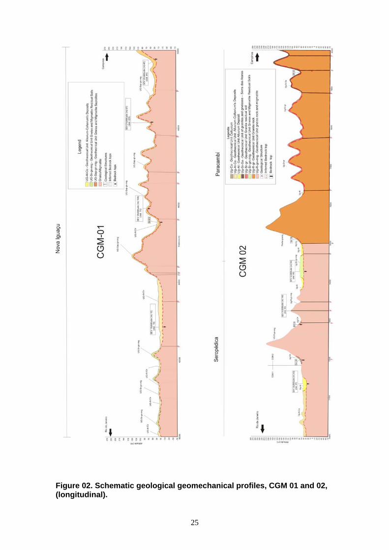
For each section with different geomechanical behavior, a table is presented containing the following information: lithology, groundwater conditions, depth and bedrock characteristics, geological-structural features, geotechnical condition, indicative features of geological risk, identification of local drilling grid and, finally, a geological and geomechanical description. This information of each section is standardized into classification groups according to the type or variation range, as shown in Table 3. The Tables 4 to 13 contain these data and descriptive summaries of these sections with differentiated geomechanical behavior (CGM), and the figures 02 to 06 show the respective schematic geological geomechanical profiles (longitudinal).
20
-1000
100
200
300
400
500
600
700
800
900
010
020
030
040
050
060
0
Prog
ress
iva
(km
)
Cota (m)
CG
M01
- (0
00 -
075
km)
CG
M02
- (0
75 -
102
km)
CG
M03
- (1
02 -
144
km)
CG
M04
- (1
44 -
177
km)
CG
M05
- (1
77 -
218
km)
CG
M06
- (2
18 -
334
km)
CG
M07
- (3
34 -
385
km)
CG
M08
- (3
85 -
414
km)
CG
M09
- (4
14 -
481
km)
CG
M10
- (4
81 -
511
km)
CG
M -
01
CG
M -
02C
GM
- 03
CG
M -
04
CG
M -
05C
GM
- 06
CG
M -
07
CG
M -
08
CG
M -
09
CG
M -
10
Figure 1. Geomechanical behavior sections along the TAV tracing (chainage in km).
Altitude (m)
Cha
inag
e (k
m)
21
Table 3. Classification of the main parameters for description of the geomechanical behavior sections.
Feature Description
L1
Transported soil(cut and fill, colluvium, alluvium and fluvial-marine sediments, in layers with variable thickness and interlayered thickness).
L2
Colluvium-Alluvium deposit
L3
Residual soil of crystalline rock
L4
Residual soil of sedimentary rock
Lithology
L5
Residual soil of metasedimentary rock
W1
Dry Massif
W2
Seepage or shallow NA up to 3 m depth
W3
NA from 3 to 10 m depth
W4
NA from 10 to 20 m depth
Water
Conditions (Water Table Depth - NA)
W5
Deep NA (over 20 m) or following the nearness of the contact soil-rock
T1
Flat bedrock Top
T2
Slightly Undulated Bedrock Top
T3
Undulated Bedrock Top
T4
Abrupt strike change of bedrock top
Bedrock Top
T5
Abrupt change of bedrock Top in two directions ( "egg box")
G1
Soil subjected to liquefaction (non-cohesive, soft, and saturated)
G2
Soft Soil (low resistance and very compressible)
G3
Soil too permeable (excessive percolation)
G4
Collapse soil (excessive and sharp sediment)
Geotechnical characteristic
G5
Expanded Soil
E1
Area with low density of discontinuities
E2
Area with medium density of discontinuities
E3
Area with high density of discontinuities
E4
Pressure release joints that follows the hills morphology (spheroidal weathering - "dome-shaped form ")
Geological-structural
features
E5
Density ranges of shear zones, faults or excessive fracturing
22
P1 Soil subjected to liquefaction P2 Soft soils P3 Very permeable soil P4 Collapse soils P5 Expanded soils P6 Alteration weathering horizon at great depths,
following discontinuities areas, with possible water flow
P7 Surface cover subjected to gravitational mass movements and erosion
P8 Boulders field (loose rock blocks and embedded in soils)
P9 Valleys filled in colluvial-alluvial sediments P10 Large thickness talus subject to instability P11 Sand Pits (some covered with water bodies)
P12 Peat layers, with possible lignite occurrence
(spontaneous combustion)
Geological Risk features
P13 Karst
Table 4. Data and summary of the Baixada Fluminense Plain CGM-01 (km 000-072).
Feature Description
Lithology
L1 Transported soil (cut and fill, colluvium, alluvium and fluvial-marine sediments, in beds with variable interlayered thickness).
Water
Conditions
W2 Seepage or shallow NA, up to 3 m depth (ranging from 1 to 20 m).
Bedrock Top
T3 Undulated bedrock top over crystalline rocks, with abrupt changes in depth (range: 4 to 56 m) in any direction.
Geological-structural features
E1 Low density of discontinuities (predominantly sub vertical), except in some areas (026-028 km interval, 036-037, 043-051, 073-075). It is worth noting that in emerged areas covered by sediments, this evaluation is not precise.
Geotechnical characteristic
G2 Soft soil (low resistance and / or highly compressible).
Geological Risk features
-x-
-x-
Drill Holes
SP-01 to 04 - SM-01 to 04, SM-100 to 101 - SR-01
Geophysical Surveys SEV-001-032
23
Geomechanical Description
Sediments deposited on a Hilly Terrain paleosurface (crystalline rocks), conditioned by the Guanabara graben bounded by faults of the Serra das Araras (strike NE). Sediments with variable thickness, with intercalation of soft soil (thickness of 1 to 10 m), which cause problems of cuts stability or excessive settlements and differential of cut and fills, or even lack of burden capacity. Some of these sediments are sandy, soft, and saturated, therefore subjected to liquefaction due to cyclic loading. The transition from Baixada to Serra das Araras is characterized by a succession of hills, with typical profile of weathering (residual soils on crystalline rocks). The foundations of bridges and viaducts should be supported by the bedrock top. However, because of the bedrock depth irregularity, its foundations elements can undergo rapid changes in height. Regarding the tunnels successive contacts intervals should be expected, relatively sharp, between low resistance soils and highly hard rocks, including fronts of mixed excavations, which will occur in greater numbers if the tunnels are more superficial.
Table 5. Data and summary of the CGM-02 of Serra das Araras Escarpment (km 072-102).
Feature Description
Lithology
L3 Residual soil of crystalline rocks, predominantly thick (10 to 40 m).
Water
Conditions
W5
NA following the nearness contact of soil and bedrock.
Bedrock Top
T5 Outcrop of the bedrock top or when in depth (0 to 40 m), irregular, following the hills morphology of the hills escarpment, but also structurally controlled by geological features.
Geological-structural features
E3 E4 E5
Areas of high density of discontinuities (faults, fractures and shear zones), predominantly sub vertical, with strike towards northeast (perpendicular to the longitudinal axis of the TAV tracing) and secondarily a second family with NW strike (sub parallel to the TAV tracing axis). The NE discontinuities follow the foliation and the NW are tension features and water store. NE faults dipping moderately are also expected.
24
Pressure release joints that follow the hills morphology (spheroidal weathering, dome-shaped-form.) Density ranges of shear zones and faults.
Geotechnical
Condition
-x-
Geological Risk features
P6 P7
Alteration of weathering crust at great depths, following discontinuities areas in any directions (NE and NW), with possible water flow. Surface covers, subjected to gravitational mass movements and erosion.
Drill Holes
SP-05 - SM-05 to 10, SM-102 - SR-02 to 06
Geophysical Surveys
SEV-033-045
Geomechanical Description
The Serra das Araras escarpment is a successive sequence of granitic and gneissic rocks intercalations, which contacts follow the direction of the main structure (NE). Such rocks are quartz-rich and have high hardness and resistance when unaltered. It has a typical weathering profile, with thick soil levels (10 to 40 m), followed by fractured and weathered rocks (5 to 10 m) until reaching the sound bedrock of high resistance. The soils derived from this type of rock usually have sandy-silt matrix, which makes these soils subject to surface erosion and slope instability. On the other hand, the burden capacity for cuts and fills is good. The contact between soil and weathered and fractured rock usually concentrate water and form a belt with an unfavorable geomechanical characteristic to cuts, where also can appear tension joints. The presence of biotite levels concentrated in gneiss, when altered, can generate discontinuities of low resistance along the foliation. Because of the large thickness of the residual and weathered soils, the tunnel openings can be extensive and subject to instabilities. Once on the rock, it is a self-supporting massif, but subject to the discontinuities presence (shear zones, faults and fractures), more severe in depth by weathering and water flow.
Table 6. Data and summary of the CGM-03 of the Paraiba do Sul River Valley Hilly Terrain – State of Rio de Janeiro (km 102-144).
Feature Description
Lithology
L3
Residual soil of crystalline rocks, predominantly shallow.
Water
Conditions (NA)
W1 W5
Dry Mass or NA following the nearness of the soil- rock contact
Bedrock Top
T3 Outcrop of the bedrock top or when in depth (0 to 15 m), undulated following the hills morphology. Greater depths are found near discontinuities areas due to the alteration weathering horizon.
Geological-structural features
E2
E4
E5
Areas with medium density of discontinuities, predominantly sub vertical, with strike to NE and NW. The NE discontinuities follow the foliation and NW features are tension zones with water flow. The NW features become more important, as demonstrated by the Paraíba do Sul river lineament, which follows the same trend to a great extent, as well as bounds the western boundary of the Resende sedimentary basin. These NW structures should be viewed carefully because they clearly control the drainage, the boundaries of the Resende basin, and also the presence of an alkaline rock, which indicate that these structures in this region may be subjected to much more tension than the surrounding areas. Pressure release joints that follow the hills morphology (spheroidal weathering - dome-shaped form). There is a concentration of NE shear zones and faults.
Geotechnical
Condition
-x-
Geological Risk features
P6
P7
P8
P9
Alteration weathering horizon at great depths, following the fault zones and fractures in any directions (NE and NW), with possible water flow. Surface covers subjected to gravitational mass movements and erosion. Boulders fields (released rock blocks embedded in soil).
27
Filled in valleys with colluvium-alluvium sediments, out of the present channel of the Paraíba do Sul river.
Drill Holes
SP- 06 to 08 - SM-11 to 14 – SR - 103
Geophysical Surveys
SEV- 046 to 075
Geomechanical Description
The Paraiba do Sul Hilly Terrain – Rio de Janeiro state - is also a successive sequence of granitic and gneissic rocks intercalations, which contacts follow the strike of the main structure (NE). It has a typical weathering profile of change due to, with residual shallow soil layers, followed by fractured and altered rocks (5 to 10 m) until reaching the sound bedrock of high resistance. The soils derived from this type of rock often have sandy-silt matrix, derived from unaltered granites, of sandy clay, when originated from gneissic rocks, which make them subjected to surface erosion and increasing slope instability. On the other hand, the burden capacity for cuts and fills is good. The contact between soil and altered and fractured rock usually stores water and form a band with a geomechanical characteristic unfavorable to cuts, where might also appear pressure release tension joints. The presence of biotite in gneissic rock, when altered, can generate discontinuities with low resistance. Once on the sound rock, it is a self-supporting massif, but subjected to the presence of discontinuities (shear zones, faults and fractures), which become more severe in depth by weathering and water percolation.
28
Table 7. Data and summary of the CGM-04 Resende Valley (km 144-177).
Feature Description
Lithology
L3 L4 L2
Residual soil from crystalline rocks, with residual soil occurrences from sedimentary rocks. Colluvium-Aluvium deposits predominantly thick (10 to 50 m), as well.
Water Conditions
W1 W5
W2/3
Dry massif or NA following the proximities of the contact of soil-rock in the hills that make up the slopes of the shallow valley NA up to 10 m in the sediments.
Bedrock Top
T3 T4
Very irregular bedrock top depending on the lithological variations, with depths of up to 15 m, following the morphology of the hill slopes and far greater depths in the valleys filled in with sediments (10 to 50 m).
Geological-structural features
E ½
E4
Areas of low to medium density of discontinuities, predominantly sub vertical, with NE and NW directions (NE discontinuities follow the foliation and NW are tension features and water stores). The Paraíba do Sul river plain has its direction controlled by these NE and NW features. Pressure release joints that follow the hills morphology of the hills (spheroidal weathering –“dome-shaped” form).
Geotechnical
Condition
-x-
Geological Risk features
P6
P7
P8
P9
P10
Alteration weathering horizon at great depths, following the fault zones and fractures in all directions (NE and NW), with possible water flow. Surface cover subjected to gravitational mass movements and erosion. Field boulders (released rock blocks embedded in soil). Filled-in valleys with colluvium-alluvium sediments, in the current of the graben of the Paraíba do Sul river and tributary river valleys. Very thick talus in its bottom portion, subjected to instability.
29
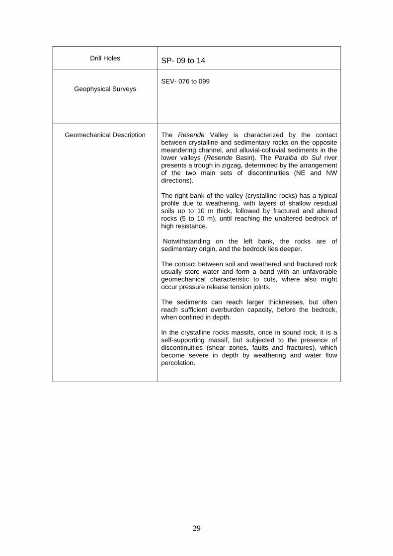
Drill Holes
SP- 09 to 14
Geophysical Surveys
SEV- 076 to 099
Geomechanical Description
The Resende Valley is characterized by the contact between crystalline and sedimentary rocks on the opposite meandering channel, and alluvial-colluvial sediments in the lower valleys (Resende Basin). The Paraiba do Sul river presents a trough in zigzag, determined by the arrangement of the two main sets of discontinuities (NE and NW directions). The right bank of the valley (crystalline rocks) has a typical profile due to weathering, with layers of shallow residual soils up to 10 m thick, followed by fractured and altered rocks (5 to 10 m), until reaching the unaltered bedrock of high resistance. Notwithstanding on the left bank, the rocks are of sedimentary origin, and the bedrock lies deeper. The contact between soil and weathered and fractured rock usually store water and form a band with an unfavorable geomechanical characteristic to cuts, where also might occur pressure release tension joints. The sediments can reach larger thicknesses, but often reach sufficient overburden capacity, before the bedrock, when confined in depth. In the crystalline rocks massifs, once in sound rock, it is a self-supporting massif, but subjected to the presence of discontinuities (shear zones, faults and fractures), which become severe in depth by weathering and water flow percolation.
Table 8. Data and summary of the CGM-05 Queluz Hilly Terrain (km 177-218).
Feature Description
Lithology
L3
Residual soil of crystalline rocks, with thickness from 5 to 50 m.
Water Conditions
(NA)
W1 W5
W2/3
The hills, dry massif or NA following the nearness of the contact soil and rock. In the filled-in valleys (filled in with sediments), NA between 2-10 m depth.
Bedrock Top
T3
Outcrop of bedrock top or when in depth (0 to 50 m), following the hills morphology. The greatest depths are found close to alteration weathering change horizon.
Geological-structural features
E 2
E4
Medium density areas of discontinuities, predominantly sub vertical, with in NE and NW directions. The NE discontinuities follow the foliation and NW are tension features where water percolates. The NE features are predominant along the lineament of the Paraíba do Sul river, although there are also sudden changes of direction due to the NW structures. A third set of discontinuities appear, with less frequency, striking N, which is perpendicular to the longitudinal axis of the TAV tracing. Pressure release tension joints that follow the morphology of the hills (weathering exfoliation – “dome-shaped form”).
Geotechnical
Condition
-x-
Geological Risk features
P6
P7
P9
Alteration weathering horizon at great depths, following the fault and fractures zones in any directions (NE and NW), with possible water occurrence. Surface covers subject to gravitational mass movements and erosion. Valleys filled in with colluvium-alluvium sediments, out of the current chute of the Paraíba do Sul river.
Drill Holes
SP- 15 to 23 – SM- 15 to 20
Geophysical Surveys SEV- 100 to 123
32
Geomechanical Description
The hills of the Alto de Queluz belong to a paragneissic unit (biotite gneiss), along all the intervals (occurrence of alkaline rocks to the north). A typical weathering profile consists of residual soils and saprolite, fairly thick (5 to 40 m), followed by altered and fractured rocks (5 to 10 m), until reaching the unaltered bedrock of high resistance. The soils derived from this rock generate slopes subjected to superficial erosion and slopes instability. On the other hand, the burden capacity to cuts and fills are good. Significant presence of talus occurs, composed ofheterogeneous material, unfavorable for foundations embankments and cuttings. The sediments that cover the filled-in valleys can reach large thicknesses, but often offer sufficient burden capacity, below the bedrock top, when confined at depth. The contact between soil and weathered and fractured rock usually store water and form a zone with geo-mechanical characteristic unfavorable to cuts, where also tension joints might occur. The presence of biotite in gneiss rock, when altered, can generate discontinuities of low resistance. Once on sound rock, it is a self-supporting massif, but subjected to the presence of discontinuities (shear zones, faults and fractures), which become more intense in depth by weathering and water percolation.
33
Table 9. Data and summary of the CGM-06 Taubaté Basin (km 218-334)
Feature Description
Lithology
L2 L4
Alluvium-colluvium deposits, with thickness ranging from 5 m to tens of meters, interlayered of residual soil of sedimentary rocks with thickness of 5 to 20 m
Water
Conditions (NA)
W2 to
W5
In the alluvium-colluvium deposits, the NA varies from superficial to very deep, depending on the proximity of water bodies. Uphill, the NA follows the proximities of the contact soil and rock.
Bedrock Top
T5
Irregular bedrock top of sedimentary rocks, which can be unconsolidated in the first 20 m, with sudden changes in thickness (5 to 70 m) according to such unconsolidated material and the existence of many paleochannels of the river.
Geological-structural
features
E1
Low density zones of discontinuities (sub vertical), with predominance of NE features along the valley lineament, although there are also sudden changes of the river direction due to NW structures.
Geotechnical
Condition
G2
Excessive and differential settlements due to interlayered soft soil layers in the sediments and sudden changes of the bedrock top.
Geological Risk features
P1
P2
P5
P9
P11
P12
Liquefaction potential in soft sandy saturated soil layers and saturated due to cyclic loads. Erratic presence of interlayered soft soil beds in sandy and gravel sediments. Occurrence of expanded soils in the valley bottoms and slopes of the sedimentary basins. Filled-in valleys with colluvium-alluvium sediments, out of the present channel of the Paraíba do Sul river. Sand pits, with varied depths from 5 to 50 m, some covered with water bodies. Some continuous layers, laterally and in depth, with occurrence and peat exploration, with significant thicknesses.
34
(5 to15 m), with possible occurrence of lignite (spontaneous combustion).
Drill Holes
SP- 24 to 29 – SM-21
Geophysical Surveys
SEV- 123 to 174
Geomechanical Description
The Taubaté Basin is characterized by colluvium-alluvium thick deposits (up to tens of meters) lying on sedimentary rocks. The Paraiba do Sul river runs predominantly in the NE direction, forming many meanders and paleochannels, which contribute to the sudden variations of the bedrock top, which is also controlled by the tectonic that gave rise to the graben of the Paraíba do Sul river. The base rocks are of sedimentary origin and havevariable resistance according to their origins, ages and depths. Among the transported soil, prevail the non-cohesive soils (sands and gravels), but that may be interlayered with soft soil layers, including thick seams of peat. It is expected that within the meanders, clay sediments occur. Usually, the sand sediments and gravel can offer satisfactory load capacity, before the bedrock top, when confined in depth. The erratic occurrence of soft soil layers and the sudden changes of bedrock indicate the need for investigations to define the appropriate profile of overburden capacity. This depends on the type of engineering solution (type of work). This irregularity of the bedrock is crucial when the TAV tracing goes to the north, near to the contact between basin and the crystalline basement, due to the occurrence of tectonic moving areas. Finally, it should be highlighted the potential for instability of the sand pit walls and liquefaction of soft and saturated sandy soil layers caused by cyclic loads.
35
Figure 04. Geological and geomechanical profiles, CGM 05 and 06, schematic (longitudinal).
36
Table 10. Data and summary of the CGM-07 Arujá Structural High (km 334-385).
Feature Description
Lithology
L3 L4
Residual soil of crystalline and sedimentary rocks, with thickness from 5 to 50 m.
Water
Conditions (NA)
W1 W5
W2/3
Up hills, dry massif or NA following the nearness of the soil-rock contact.In the filled-in valleys (sediments), NA between 2-10 m depth.
Bedrock Top
T5
Outcrop of the bedrock top or when in-depth (5 to 50 m) following the hills morphology. The greatest depths are found close to the alteration weathering horizon.
Geological-structural
features
E2 E4
In the massif of crystalline rocks (gneiss and granitic rocks), zones with medium density of discontinuities, predominantly sub vertical, with strikes NE and NW. NE discontinuities follow the foliation and NW are tension features and water bearing terrains. Pressure release joints that follow the morphology of the hills (weathering exfoliation – “dome-shaped form”).
Geotechnical
Condition
-x-
Geological Risk features
P6
P7 P8
P9
Alteration weathering horizon at great depths, following the fault and fractures zones in any directions (NE and NW), with possible water occurrence. Ground areas subjected to erosion. Occurrence of loose granite blocks (superficial boulders embedded in soils). Valleys filled-in with colluvial-alluvial sediments, with significant thickness and presence of more superficial NA.
Drill Holes
SP- 30 to 32 – SM-22 to 24
37
Geophysical Surveys
SEV- 175 to 214
Geomechanical Description
The Arujá Structural High is characterized by a structural high that separates the sedimentary basins of Taubaté and São Paulo, and is composed of bodies of granitic and gneissic rocks on the high itself, which contacts follow the NE direction. Usually, the rock massif has two typical profiles, one due to weathering, with layers of very thick residual soils (5 to 50 m), and another with sound bedrock outcrops, showing high resistance. The overburden capacity of the terrains seems to be good, but small scars indicate slope instability and erosions on the steeper slopes. The contact between soil and weathered and fractured rock usually store water and form a zone with a geo-mechanical characteristic unfavorable to cuts, where also pressure release tension joints might occur. There are few valleys filled in with colluvium-alluvium sediments, which thickness can reach the order of meters or tens of meters. In massif of crystalline rock, once in a sound rock, it is a self-supporting massif, but subjected to the presence of discontinuities (shear zones, faults and fractures), which become more intense by deep weathering due to water percolation.
Table 11. Data and summary of the CGM-08 São Paulo Basin (km 385-414).
Feature Description
Lithology
L2 L4
Alluvium-colluvium deposits, with thickness ranging from 5 m to tens of meters, with residual soil originated from sedimentary rock, with thickness from 10 to 20 m
Water
Conditions (NA)
W2/3
In the alluvium-colluvium deposits, the water level (NA) varies from superficial to moderately deep, depending on the nearness of water bodies.
Bedrock Top
T5
Irregular bedrock top with sedimentary rock, thickness from 5 to 50 m lying on crystalline rocks, as paleosurface of the São Paulo Basin (some intercalations of
38
crystalline rocks have, side by side, high-resistance rock bodies, unconsolidated sediments and residual soils).
Geological-structural
features
-x-
Geotechnical
Condition
-x-
Geological Risk features
P2
P4
Erratic presence of soft soil layers interbedded with sandy sediments and gravels. Occurrence of collapse soils on tops of hills or ridges.
Drill Holes
SP- 33 – SM-25 to 30
Geophysical Surveys
SEV- 215 to 230
Geomechanical Description
The São Paulo Basin is characterized by thick colluvium-alluvium deposits (up to tens of meters) lying on sedimentary rocks, and irregular crystalline rocks. The northern border of the basin, near the contact with the basement, through which the TAV tracing runs is a tectonic moving region, subjected to variation in the depth of bedrock ("mini-grabens with great depth, occurrence of Tertiary sediments and basement). Near the Guarulhos airport appears one of these "mini grabens, which characterizes an important factor of this project. The rocks of the basin are of sedimentary origin and have variable resistance depending on their origins, ages and depths. Among the transported soil, the non-cohesive soils (sands and gravels) predominate, but that can be interlayered by beds of soft soil. Usually, only offer satisfactory burden capacity before the bedrock, when confined in depth. Some layers of sedimentary soils are placed upon residual soils and altered from sedimentary or crystalline rocks, which contribute to sudden changes in geomechanical characteristics.
Table 12. Data and summary of the CGM-9 Jundiaí Hilly Terrain (km 414-481).
Feature Description
Lithology
L3 L5
Residual soil of crystalline rocks and metasedimentary rocks, predominantly thick (5 to 60 m).
Water
Conditions (NA)
W1 W5
Dry massif or deep NA following the nearness of the of soil-rock contact.
Bedrock Top
T3
Irregular bedrock top with depths between 5 and 40 m. at much greater depths are found close to discontinuities zones due to the alteration weathering change horizon. Also in the karstic areas, the bedrock may present sudden change due to the presence of caverns.
Geological-structural
features
E 2/3
E4
E5
Medium to high concentration zones of discontinuities, predominantly sub vertical, with NE and NW strikes. The NE discontinuities follow the foliation and the NW are tension features and water bearing terrains. The NE features bounds the contacts between the different rock types along this interval. The contacts between different rock types can be sheared or very fractured. Pressure release tension joints that follow the morphology of the hills (weathering exfoliation – “dome-shaped form”). In the NE direction there are concentration of shear zones and faults.
Geotechnical
Condition
-x-
Geological Risk features
P6
P7
Alteration weathering horizon at great depths, following the fault and fractures zones in any directions (NE and NW), with possible water occurrence.
41
P8
P9
P13
Superficial cover subject to gravitational mass movements and erosion. Erratic boulders (released blocks embebbed in soil) in granitic rocks regions. Valleys filled-in with colluvium-alluvium sediments. Zones showing karstic features (Pirituba and Caieiras), elongated in the NE direction, usually under covered valleys.
Drill Holes
SP- 34 to 37 – SM-31 to 37, SM-104
Geophysical Surveys
SEV- 231 to 279
Geomechanical Description
This stretch is the most heterogeneous in terms of rock types and is characterized by an interlayered sequence of crystalline rocks bodies, schists and metasedimentary, whose contacts follow the main structure direction (NE). It has a typical profile of change due to weathering, with thick residual soils levels (5 to 60 m) followed by fractured and altered rocks (5 to 10 m) until reaching the bedrock, which has geo-mechanical characteristics differentiated depending on lithology. Usually, the burden capacity for cuts and fills is good, as well as to resistance to cut slopes, with the exception that the the slope stability may be affected by discontinuities. The contact between soil and weathered and fractured rock usually store water and form a zone with a geo-mechanical characteristic unfavorable to cuts, where pressure relief tension joints also may occur. Once on crystalline rock, it is a self-supporting massif, but subject to the presence of discontinuities (shear zones, faults and fractures), which can become worse by surrounding deep change due to water percolation. On the other hand, the metasedimentary rocks are very fractured even at great depths. It is worth noting that part of the TAV tracing passes through the TAV zone subject to the occurrence of karstic features (karstic limestones).
42
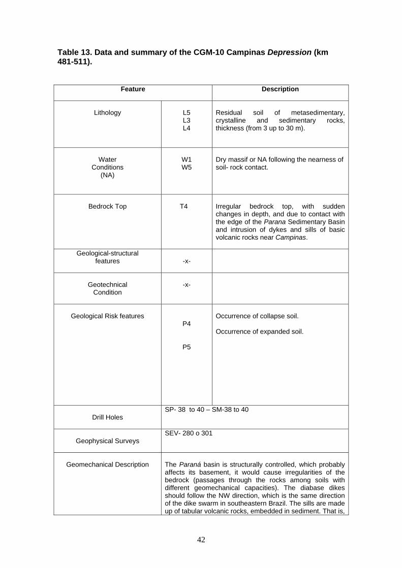
Table 13. Data and summary of the CGM-10 Campinas Depression (km 481-511).
Feature Description
Lithology
L5 L3 L4
Residual soil of metasedimentary, crystalline and sedimentary rocks, thickness (from 3 up to 30 m).
Water
Conditions (NA)
W1 W5
Dry massif or NA following the nearness of soil- rock contact.
Bedrock Top
T4
Irregular bedrock top, with sudden changes in depth, and due to contact with the edge of the Parana Sedimentary Basin and intrusion of dykes and sills of basic volcanic rocks near Campinas.
Geological-structural features
-x-
Geotechnical
Condition
-x-
Geological Risk features
P4
P5
Occurrence of collapse soil. Occurrence of expanded soil.
Drill Holes
SP- 38 to 40 – SM-38 to 40
Geophysical Surveys
SEV- 280 o 301
Geomechanical Description
The Paraná basin is structurally controlled, which probably affects its basement, it would cause irregularities of the bedrock (passages through the rocks among soils with different geomechanical capacities). The diabase dikes should follow the NW direction, which is the same direction of the dike swarm in southeastern Brazil. The sills are made up of tabular volcanic rocks, embedded in sediment. That is,
43
the Campinas Depression is an area covered by thick residual soils, interlayered sediments with different burden capacity on metasedimentary rocks, and some dykes intrusion and sills of basic rocks with high strength. The soils derived from these rocks offer good resistance and burden capacity. However, there are expanded soils in the sediment below and collapse soils on the tops of hills. There are valleys filled in with alluvial deposits, where the water levels are more shallow (3-10 m). Once on the rock, both crystalline and metasedimentary and sedimentary rocks, it is a self-supporting massif, but subjected to the presence of discontinuities (shear zones, faults and fractures, beddings and contacts), which become more severe by deep weathering due to water percolation.
44
Figura 06. Schematic geological geomechanical profiles, CGM 09 and 10, (longitudinal).
45
V.2. Identification of Risk Events Since the conceptual geological and geomechanical models have been conceived for the different geomechanical behavior sections (CGM), an association with the engineering types of works proposed for each interval and respective most relevant interferences were done, and the results of the identification of potential risks events are here discussed. It is not the purpose of this report to carry on a risk analysis (qualitative or quantitative), assessing the probabilities of occurrences and respective impacts (consequences), but only identify the events that may cause risks. Finally, some recommendations for risk mitigation measures are also given, ie those with potential to eliminate risk sources or minimize them. Tables 14 to 23 show the results of this identification analysis of potential risk events for each CGM. Table 14. Identification of potential risk events and mitigation measures for the CGM-01 Baixada Fluminense (Rio de Janeiro Plain) (km 000-072). Description
Type of Work
PV TU
The predominant work for this section will be tunnels (TU), bridges and viaducts (PV), with great dimensions, supplemented by cuts and fills (AT) and cuts (CT).
Interferences
AU ER IT
Urban Area Buildings of great importance ( Manguinhos oil refinery and UFRJ-Federal University of Rio de Janeiro buildings) Transport infrastructure (roads and Antônio Carlos Jobim airport runway)
Potential Risk Events
General
Intercalations of sediments layers of low support capacity and very compressible (soft soil), with outcropping or shallow NA: � AT - excessive and differential settlements; which become more severe by irregular bedrock, or even lack of overburden capacity; � CT - instability of slopes and inflow of water.
Local
Manguinhos Oil Refinery – possible occurrence of soils contaminated with hydrocarbons, which areas require special care, as well as an excavation system and careful transports.
46
UFRJ Buildings - possible judicial litigation regarding its expropriation (depending on the building purpose, new installations must be built before its demolishment). Galeão (Antônio Carlos Jobim) airport Runway - tunnel with low cover, with great impact in case of accidents. Urban Area: � TU - control of settlements and stabilities of the front mining; � CT and TU - probable judicial litigation regarding the expropriation. Serra das Araras escarpment - crystalline rocks with a weathering profile and with soils subjected to slope instability and erosion: � CT and TU - short tunnels sequence with cuts and openings of great height, with instability risk of the slopes and opening, as well as difficult conditions for the tunnels (mixed front and roof diggings in more unfavorable materials).
Mitigation measures
General
More detailed geological and geotechnical investigations, interpreted in the light of the engineering geology techniques in order to improve the local geological and geomechanical model, minimizing the uncertainties and contributing to a more appropriate program of risk management. It is essential to get the precise definition of the bedrock for the PV foundations and anticipate the front changes in the TU excavation. The TU excavation method must provide equipment capable of dealing with sudden changes of geomechanical characteristics, the mixed excavated front and the presence of water. With the quartz content of some crystalline rocks, this magnitude should be measured, as it affects the definition of digging tools. Because it is an urban area, sensitive to subsidence, the method should provide effective control of repression and NA, such as pressurizing of the excavated front.
47
To minimize the number of mixed fronts and abrupt changes of materials, it is possible to seek alternative routes that will favor deeper tunnels. Avoid platform infrastructure (cuts and embankments) or implement engineering measures (improving and upgrading) for additional engineering control settlements and increased support capacity of the terrains.
Local
Change the tracing to avoid the interval below the Manguinhos oil refinery, or check if there is contamination of the surroundings by hydrocarbons. Change the tracing or the type of work for tunnel or viaduct to avoid confrontation with the UFRJ buildings. Anticipate the tunnel opening to increase the tunnel cover under the Galeão airport runway, or discontinue the runway access, if possible. Change the path in the interval corresponding to Serra das Araras escarpment, in order to minimize the cuts height and the number of openings, i.e. making a deeper tracing.
Table 15. Identification of potential risk events and mitigation measures for the CGM-02 Serra das Araras Slope (km 072-102).
Description
Type of Work
TU
The predominant works of this section are tunnels (TU) with large dimensions, supplemented with bridges and viaducts (PV) and cuts (CT).
Interferences
RB
Existence of a reservoir of the Ribeirão das Lajes dam (not too close to the TAV tracing).
Potential Risk Events
General
Very irregular undulated bedrock top in both directions due to high concentration areas of discontinuities (faults, fractures and shear zones), predominantly sub vertical, with strike
48
towards northeast (right angle to the longitudinal TAV tracing axis) and a second set with NW trend (sub parallel to the TAV tracing axis). The NE discontinuities follow the foliation and NW are tension features and water bearing rocks. Faults in the NE direction and dipping sub vertically are also expected. The alteration weathering horizon is very deep following the concentration ranges of discontinuities: � TU - abrupt changes of the geo-mechanical characteristics of the dug materials, occurrence of mixed excavated front (soil, weathered rock and sound rock) and water presence, which will occur in the passages through shear zones and faults; � PV - foundation elements with varied depths, some very deep. Superficial soils subject to erosion and gravitational mass movements, aggravated by high rainfall of the region: � PV - movements over the pillars and foundation elements; � CT - Instability of cuts slopes and opening, with very negative impacts for the Project.
Local
Interference of the works of the dam and its reservoir.
Mitigation measures
General
More detailed geological and geotechnical investigations, interpreted in the light of the engineering geology techniques in order to improve the geological and geomechanical model site, minimizing the uncertainties and contributing to a more appropriate risk management program. It is essential to get the precise definition of the bedrock for the foundations of PV and anticipate changes in the TU excavation fronts. The TU excavation method must provide equipment capable of dealing with sudden changes of geomechanical characteristics, the mixed excavation fronts and water seepage. Because of the quartz content of some crystalline rocks this magnitude should be measured, as it affects the definition of digging tools. Due to the presence of NA at located points (shear zones and faults), the method must provide its effective control, such as pressurization, injections and
49
excavation fronts investigations. To minimize the number of mixed fronts and abrupt changes of materials in tunnels and cut heights and openings, it is possible to seek alternative paths to dig favorable deeper tunnels. Alternative routes must be sought that will minimize the work surface, since the slope of the mountain has a large inherent instability. In cases where cuts and openings are necessary use additional engineering measures (hillside – slope - protection, massif treatment and drainage) to ensure its stabilization in acceptable risk levels as well as to protect the pillars and foundation elements of the PV regarding the events of gravitational mass movements.
Local
Studies and hydrogeological investigations to estimate the works influence of tunnels in the dam and its reservoir.
Table 16. Identification of potential risk events and mitigation measures for the CGM-03 Paraiba do Sul Hilly Terrain (Rio de Janeiro state) (km 102-144). Description
Type of Work
PV TU
The predominant works of this section are bridges and viaducts (PV), followed by tunnels (TU), supplemented by cuts (CT) and cuts and fills (AT).
Interference
IT
Large highways, but without serious impact.
Potential Risk Events
General
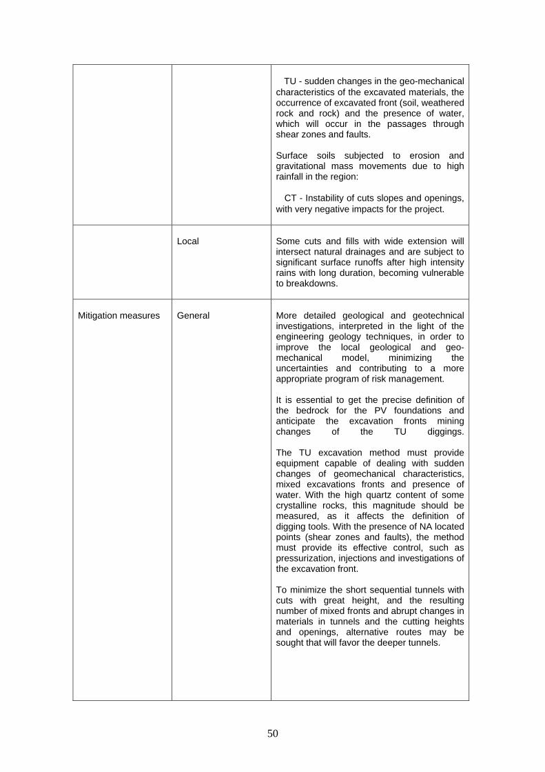
Undulated bedrock top, more shallow (0 to 15 m), following the hills morphology Deeper variations occur close to concentrations of discontinuities (faults, fractures and shear zones). Although less critical, this variation of the bedrock and the consequent changes of high strength rocks with low areas (soils and altered rocks), more severe with filled-in valleys, remains the main local constraint: � PV - foundation elements with varied depths, very deep. Attention should be paid to the presence of boulders, which may distort the identification of the bedrock top;
50
� TU - sudden changes in the geo-mechanical characteristics of the excavated materials, the occurrence of excavated front (soil, weathered rock and rock) and the presence of water, which will occur in the passages through shear zones and faults. Surface soils subjected to erosion and gravitational mass movements due to high rainfall in the region: � CT - Instability of cuts slopes and openings, with very negative impacts for the project.
Local
Some cuts and fills with wide extension will intersect natural drainages and are subject to significant surface runoffs after high intensity rains with long duration, becoming vulnerable to breakdowns.
Mitigation measures
General
More detailed geological and geotechnical investigations, interpreted in the light of the engineering geology techniques, in order to improve the local geological and geo-mechanical model, minimizing the uncertainties and contributing to a more appropriate program of risk management. It is essential to get the precise definition of the bedrock for the PV foundations and anticipate the excavation fronts mining changes of the TU diggings. The TU excavation method must provide equipment capable of dealing with sudden changes of geomechanical characteristics, mixed excavations fronts and presence of water. With the high quartz content of some crystalline rocks, this magnitude should be measured, as it affects the definition of digging tools. With the presence of NA located points (shear zones and faults), the method must provide its effective control, such as pressurization, injections and investigations of the excavation front. To minimize the short sequential tunnels with cuts with great height, and the resulting number of mixed fronts and abrupt changes in materials in tunnels and the cutting heights and openings, alternative routes may be sought that will favor the deeper tunnels.
51
Considering the operational risk of the project caused by any slope instability, in cases where cuts and opening are needed, use additional engineering measures (hillside -slope- protection, massif treatment and drainage) to ensure its stabilization at acceptable risk levels.
Local
Deal with the drainage measures of the cuts and fills (size of drainpipe and infiltration gallery), considering the rainfall intensity of the region and its position in relation to natural drainage basins and correspondent infiltration basin.
Table 17. Identification of potential risk events and mitigation measures for the CGM-04 Resende Valley (km 144-177). Description
Type of Work
PV
This section is characterized by some viaducts, bridges (PV) of great extension, near Resende and then cuts sequence (CT), cut and fill (AT) and short tunnels (TU).
Interferences
IT RB
Highways, but without further interactions. Reservoir of Funil dam, but in a favorable position in relation to the proposed tracing.
Potential Risk Events
General
Undulated bedrock top following the hills morphology, but subjected to abrupt change of depth due to the valleys filled in with sediments. This change of the bedrock and the consequent changes of high resistance rocks with low areas (soils and altered rocks), which are more severe with valleys filled in maintain the same local condition: � PV - foundation elements with varied depths, some much deeper. Attention should be paid to the presence of boulders, which may distort the determination of the bedrock top; � TU - variations of the geomechanical characteristics of the excavated materials, occurrence of mixed excavation fronts (soils, altered rock and rock) and the presence of water, which may occur in the passages
52
through shear zones and faults. Surface soils subject to erosion and gravitational mass movements: � CT - Slopes instability and openings, with very negative impacts for the project operation.
Local Occurrence of foothills talus, which can be unstable.
Mitigation measures
General
More detailed geological and geotechnical investigations, interpreted in the light of the engineering geology techniques in order to improve the local geological and geo-mechanical model, minimizing the uncertainties and contributing to a more appropriate risk management program. It is essential to get the precise definition of the bedrock for the PV foundations and anticipate the front changes in the TU excavation. The TU excavation method must provide equipment capable of dealing with sudden changes in geomechanical characteristics, mixed excavation fronts and water presence. Because of the NA presence at located points (shear zones and faults), the method must provide its effective control, such as pressurization, injections and excavation fronts investigations. To minimize the short sequential tunnels with high cuts, and the resulting number of mixed fronts and sudden changes of materials in the tunnels and the cutting heights and openings it is possible to seek alternative tracings that may favor the deeper tunnels excavation. Considering the operational risk of the project caused by any instability of slopes, in cases where cuts and openings are needed, it is recommended to use additional engineering measures (hillside –slope - protection, massif treatment and drainage) to ensure its stabilization at acceptable risk levels.
Local Change tracing to avoid talus areas, or investigate better its stabilizing characteristics.
53
Table 18. Identification of potential risk events and mitigation measures for the CGM-5 Queluz Hilly Terrain (177-218 km). Description
Type of Work
TU PV
This section is characterized by a tunnels sequence (TU) and viaducts bridges (PV), supplemented by cuts (CT), some with great heights.
Interferences
IT
Roads and railways, but without further interactions.
Potential Risk Events
General
The bedrock top varies from outcrop up to 50 m deep, which, combined with valleys filled in with sediments, again constitutes an important determinant of the project: � TU - variations in geomechanical characteristics of the excavated materials, the occurrence of mixed excavation front (soils, weathered rock and rock) and water presence, which may occur in the passages by shear zones and faults; � PV - foundation elements with varying depths, some very deeper. Surface soils subject to erosion and gravitational mass movements: � CT - Slopes instability and openings, with very negative impacts for the project operation.
Local
Occurrence of foothills talus, which may be unstable.
Mitigation measures
General
Detailed geological and geotechnical investigations, interpreted in the light of the engineering geology techniques in order to improve the local geological and geo-mechanical model, minimizing the uncertainties and contributing to a more appropriate risk management program. It is essential to get the precise definition of the bedrock top for the PV foundations purposes and anticipate changes of the TU excavation fronts.
54
The TU excavation method must provide equipment capable of dealing with sudden changes in geo-mechanical characteristics, mixed excavation fronts and water presence. Because of the NA presence locally (shear zones and faults), the method must provide its effective control, such as pressurization, injections and excavation fronts investigations. To minimize the short sequential tunnels with great high cuts and the resulting number of mixed faces and sudden changes in materials in the tunnels and cutting heights and openings, it is possible to seek alternative routes that may favor the excavation of deeper tunnels. Considering the operational risk to the project caused by any slopes instability, in cases where cuts and openings are needed, it is recommended to use additional engineering measures (containment, massif treatment and drainage) to ensure its stabilization at acceptable risk levels.
Local
Change tracing to avoid talus areas, or investigate better the characteristics of stabilization.
Table 19. Identification of potential risk events and mitigation measures for the CGM-06 Taubaté Basin (km 218-334). Description
Type of Work
PV
Interval characterized by extensive bridges and viaducts (PV), supplemented by small cuts (CT), cuts and fills (AT) and tunnels (TU).
Interferences
AU AR MA
Urban Area Rural Area (crops in lowland) Business area of environmental protection
Potential Risk Events
General
Very irregular bedrock top, covered by colluvium-alluvium sediments, with interbedded layers or pockets of soft soil,
55
including peat, filling in paleochannels of the river; and outcrop or shallow NA: � PV - depth of the foundation elements of the bridges and viaducts vary widely and need to determine precisely the bedrock for the foundation purposes.
Local
Tunnel in urban area requires effective control of settlements and NA. Some cuts and cuts and fills in urban areas can generate legal disputes, as well as the interferences with interest areas or environmental protection. Sand pits, with depths ranging from 5 to 50 m, which slopes can become unstable subjected to cyclic loads.
Mitigation measures
General
More detailed geological and geotechnical investigations, interpreted in the light of engineering geology techniques in order to improve the local geological and geomechanical model, minimizing the uncertainties and contributing to a more appropriate risk management program. It is essential to get the precise definition of the bedrock top for the PV foundations purposes.
Local
In the case of tunnels in urban areas, the chosen excavation method must have effective control of settlements and NA, such as pressurization and injections of excavation fronts. Avoid cuts and cuts and fills in urban areas leading to expropriation or urban segregation, by changing the tracing or type of work (consider tunnels or viaducts). Change tracing to avoid the sand pits region, as well as business or environmental protection areas.
56
Table 20. Identification of potential risk events and mitigation measures for the CGM-07 Arujá Structural High (km 334-385). Description
Type of Work
CT AT PV TU
This section is characterized by a cuts sequence (CT), cuts and fills (AT), viaducts bridges (PV) and tunnels (TU).
Interferences
AU IT MA RM RB
Urban Area Highways, but without further interactions. Business or environmental protection areas. Exploitation areas of mineral resources (sand pits and quarries) Reservoir of the Igaratá dam but without further interaction with the proposed tracing.
Potential Risk Events
General
The bedrock top varies from outcrop up to 50 m in depth, with abrupt changes in both directions due to the regional geological structure (NE and NW features), which constitutes an important determinant of the project: � TU – variations of the geomechanical characteristics of the excavated materials, the occurrence of mixed excavation fronts (soils, weathered rock and rock) and presence of water, which may occur in the passages through shear zones and faults; � PV - foundation elements with varying depths, some very deep, and still subjected to the presence of boulders.
Local Some cuts and cuts and fills in urban areas can generate judicial litigations, as well as the interferences with business or environmental protection areas. Sand pits, with varied depths ranging from 5 to 50 m, which slopes can become unstable subject to cyclic loads. Superficial soils, especially those derived from sedimentary rocks, are subject to expansion, which leads to instability problems of the cuts slopes (CT) and openings .
Mitigation measures
General
More detailed geological and geotechnical investigations, interpreted in the light of the engineering geology techniques in order to improve the geological and geomechanical
57
model, minimizing uncertainties and contributing to a more suitable risk management program. It is essential to get the precise definition of the bedrock top for the PV foundations and anticipate the changes of the TU excavation fronts. The TU excavation method must provide equipment capable of dealing with sudden changes of geo-mechanical characteristics, mixed excavation fronts and the presence of water. Due to the fact of the NA presence locally (shear zones and faults), the method must provide for its effective control, such as pressurization, injections and investigations of the mining front. To minimize the short sequential tunnels with high cuts, and the resulting number of mixed excavation fronts and abrupt changes of materials in tunnels and cuts and openings, it is possible to look for alternative routes that may favor the excavation of deeper tunnels.
Local Avoid cuts and cuts and fills in urban areas leading to expropriation or urban segregation, changing route or type of work (consider tunnels or bridges). Change layout to avoid the sand pits region as well as the business or environmental protection areas. Considering the operational risk to the enterprise caused by any instability of slopes, in cases where it is necessary cuts and opening, use additional engineering measures (containment, massif treatments and drainage) to ensure stabilization of acceptable risk levels.
Table 21. Identification of potential risk events and mitigation measures for the CGM-08 São Paulo Basin (km 385-414). Description
Type of Work
TU
This section is characterized by long tunnels (TU) in urban areas, complemented by cuts (CT) and cuts and fills (AT)
58
Interferences
AU IT
Urban Area (Guarulhos and São Paulo) Roads, runways and buildings from the Guarulhos airport
Potential Risk Events
General
Colluvium-alluvium deposits on residual soil of sedimentary rock, on crystalline rocks in tectonically moved environment, which have, side by side, intercalations of high-stress rock bodies, unconsolidated sediments, residual soils and altered rocks. Such situation refers to the tunnels, sudden changes of geomechanical characteristics, mixed excavation fronts and water presence.
Local
Tunnel above runway and buildings from Guarulhos airport, with significant impacts in case of accident. Cuts and cuts and fills in urban areas may require noble space for the present and future urban use.
Mitigation measures
General
More detailed geological and geotechnical investigations, interpreted in the light of the engineering geology techniques in order to improve the local geological and geo-mechanical model, minimizing the uncertainties and contributing to a more appropriate risk management program. It is essential to get the precise definition of the bedrock to anticipate the changes in the TU excavation fronts. The TU excavation method must provide equipment capable of dealing with sudden changes in geomechanical characteristics, mixed excavation fronts and presence of water. Due to the fact of being urban tunnels, effective control of settlements and NA should exist, using measures such as pressurization, injections and investigations of the excavation front.
Local
Use similar methodology to tunnels in urban areas, with effective control of settlements and of the NA, with pressurization, injections and investigations of the excavation front. Minimize cuts and cuts and fills in urban areas, changing the tracing or the type of work (consider tunnels or viaducts).
59
Table 22. Identification of potential risk events and mitigation measures for the CGM-09 Jundiaí Hilly Terrain (km 414-481). Description
Type of Work
TU PV CT
This section is characterized by tunnels (TU) and bridges and viaducts (PV) of significant size, supplemented by cuts (CT), some with great heights.
Interferences
AU IT RM
Urban area Highways Quarries
Potential Risk Events
General
Again, the irregular bedrock top constitutes an important determinant of the project, aggravated by the presence of filled in valleys (alluvium-colluvium sediments) and by the contacts between the different types of crystalline rocks and metasedimentary, also emphasizing that many of these contacts may be sheared or very fractured: � TU - variations of the geomechanical characteristics of the excavated materials, occurrence of mixed excavation front (soils, weathered rock and rock) and presence of water, which may occur in the passages through shear zones and faults; � PV - foundation elements with varying depths, some very deep, and still subjected to the presence of boulders.
Local Tunnels in urban areas - settlements and control of any instability as well as the NA control. Cuts and landfills in urban areas - possibility of judicial litigation. Cuts and cuts and fills in excavation fronts areas (quarries) - interferences in the construction material supply of the region and the work with possible litigation. Cuts excessive high with direct interference with the Bandeirantes highway- impacts due to unacceptable instability to the development and to the road system Anhanguera-Bandeirantes. Occurrence of karst areas between Pirituba and Caieiras - a risk factor for any type of
60
works, particularly tunnels, bridges and viaducts.
Mitigation measures
General
Detailed geological and geotechnical investigations, interpreted in the light of the techniques of engineering geology in order to improve the local geological and geomechanical model, minimizing the uncertainties and contributing to a more appropriate risk management program. It is essential to get the precise definition of the bedrock top in order to anticipate the changes of TU excavation fronts and positions of the foundation elements of the bridges and viaducts. The TU excavation method must provide equipment capable of dealing with sudden changes in geomechanical characteristics, mixed mining fronts and presence of water.
Local
In the case of urban tunnels, apart from the requirements mentioned above, it must have an effective control of the settlements and NA, using measures such as pressurization, injections and investigations of the mining front. Avoid cuts and cuts and fills in urban areas leading to expropriation or urban segregation, by changing TAV tracing or type of work (consider tunnels or bridges). Change tracing to avoid the regional quarries, as well as business or environmental protection areas. Considering the operational risk of the project caused by any instability of slopes, in cases where cuts and openings are necessary, use additional engineering measures (containment, massif treatments and drainage) to ensure stabilization at acceptable risk levels. Specific geological - geotechnical investigations to map the carbonate rock structures and karstic features. In the case of tunnels, implement systematic investigation in the excavation front.
61
Tabela 23. Identification of potential risk events and mitigation measures for the CGM-10 Campinas Depression (km 481-511).
Description
Type of Work
CT AT
This section begins with a long tunnel (TU) in the Viracopos airport region, and then characterized by a succession of cuts (CT) and cuts and fills (AT), complemented with bridges and viaducts (PV).
Interferences
AU IT
Urban area Highways and airport, but without further interactions.
Potential Risk Events
General
Irregular bedrock top and intrusions of dykes and sills of volcanic rock, which constitutes an obstacle to the project: � TU - abrupt changes of the geomechanical characteristics of the excavated materials, occurrence of mixed excavation fronts (soils and rock); � PV - foundation elements with varied depths, some very deep.
Local
Occurrence of collapse soil can cause abrupt and excessive settlements in cuts and fills. Occurrence of expanded soils can cause instability problems on slopes. Cuts and cuts and fills in urban areas - the possibility of judicial litigation. Tunnel in the influence area of the Viracopos airport, without direct confrontation with runways, access roads and buildings, but even so, any instability can generate significant impacts.
Mitigation measures
General
Detailed geological and geotechnical investigations, interpreted in the light of the engineering geology techniques in order to improve the geological and geomechanical model, minimizing the uncertainties and contributing to a more appropriate program of risk management.
62
It is essential to check the precise definition of the bedrock top to anticipate the changes in the TU excavation fronts and the positions of the foundation elements of bridges and viaducts. The TU excavation method must provide equipment capable of dealing with sudden changes in geomechanical characteristics and mixed excavation fronts.
Local Specific geological and geotechnical investigations to characterize the occurrence of collapse and expanded soils. Once located within the TAV tracing require dedicated engineering measures, such as settlements acceleration and heavy compression for collapse soils and superficial protection measures of the slope and sometimes to protect expanded soils. Avoid cuts and landfills in urban areas that would lead to expropriation or urban segregation, changing TAV tracing or type of work (consider tunnels or bridges). In the case of the tunnel in the influence area of the Viracopos airport, although there is no direct confrontation, measures to control settlements and NA must be adopted, such as in urban tunnels, minimizing any negative impacts in case of accidents.
VI. CONCLUSIONS AND RECOMMENDATIONS This report of the 3rd. Stage of the geological and geotechnical studies, carried out by the CPRM, after the data consolidation and results of the studies of the Stages 1 and 2, presented ten compartments of different geomechanical behavior (CGM) along the TAV tracing and its outstanding features, as well as the identification of potential risk events and respective mitigation measures. According to the results of this 3rd. Stage, it is possible to make the following considerations and recommendations: • The geological and geotechnical data available in Steps 1 and 2 and the identification analysis of the types of risks carried out in Step 3 are compatible with the planning phase (or feasibility) of a venture of similar design of the TAV project. • The proposed TAV tracing and respective types of infrastructure works for each section are those under the responsibility of the Halcrow & Synergy consortium, and at no time such responsibility of lying on studies undertaken by CPRM any forms of validation, only an identification review of risks types according to the geological and geomechanical compartments, of the infrastructure works types, of its urban and environmental interferences etc.. • It is worth noting that, whatever is the tracing proposed for the TAV, there is always the possibility of identification of risks types, but what changes from one alternative to another, is the final quantification of the associated risks, that is, the best alternative is the one technically and economically feasible and which can minimize potential risks.
63
• According to the geological and geotechnical data already available (Steps 1 and 2) the types of engineering works provided along the TAV tracing was possible to identify several potential risk events (Step 3), some applicants in all other sections and others more specific. • The most recurring source of risk events is the irregularity of the bedrock top, with large and abrupt changes in depth, which directly affects the method choice for tunnels and the elements dimensions of foundation art works (bridges and viaducts). • This irregularity of the bedrock top is more severe in the presence of shear zones and faults, deep weathering, filled in valleys, tectonically moved regions, paleochannels intrusion rocks (dykes and sills), but the sum of these factors generates alternating geomechanical characteristics along mapping, and occurrence of water in altered areas or in the contact soil-rock. • The escarpment regions of the mountains and hilly terrains are subjected to slope instability due to high slopes, intense rainfall, terrains characteristics and plans or areas of discontinuities that follow the hills morphology (eg, relief joints due to (weathering exfoliation). • Other sources of risk events that are worth mentioning: the presence of interbedded soft soil layers in more competent sediments, the occurrence of expanded soils and collapse soils layers and peat pockets. • In all these situations, the most efficient way to mitigate geological origin risk is to conduct more detailed investigations of geological and geotechnical programs compatible with the various phases of the venture project, which data can be interpreted in the light of good geological geo-mechanical engineering techniques, in order to improve the geological and geomechanical current model for each site, minimizing the uncertainties and contributing to a more appropriate risk management program. • As said before, once it is impossible to surround all the geological and geotechnical variability, a program of risk management must be implemented at all development stages, integrating the various actors (owners, designers, builders and operators), but led by independent and competent institution. • Considering the identified potential risk events in these studies, it is recommended to continue the evaluation and risk analysis, both qualitatively and quantitatively, adding apart from the geological and geomechanical variables, the hydrological, those related to construction methods, social, environmental etc. That is, a consistent risk analysis with the size, importance and impacts of the venture. • More specifically for the various types of engineering works the recommendation is that: - Tunnels – further investigation programs must include targeted surveys and necessary parameters for characterization and geomechanical classification of the different types of surrounding massifs, as well as resistance data and rocks abrasion. The tunnels methods must be used for sudden changes in geomechanical characteristics, the occurrence of mixed excavation fronts, NA presence and effective control of settlements when in urban environments; - Bridges and viaducts – due to the sudden change of the bedrock top for the burden capacity purposes, these will require specific investigations for each element of the foundation, which will have very different depths, and some very deep; - Cuts - usually will require additional engineering measures, regarding massif treatments and hillside or slope protection, since any instability can generate huge impacts in the Project operation.
64
- Cuts and Fills - in areas where sediments are prevailing, it should be considered all sources of excessive and differential settlements, otherwise such events will affect the TAV operation (schedule). • Finally, it is worth highlighting the importance of a central institution to be the depository for all the geological and geotechnical data generated in all stages of the venture, manage specifications and standards of the Project so as to control all monitoring forms and safety measurements. VII. REFERENCES CPRM (2009). Geological-Geotechnical Mapping and Geological Hazard Areas Delimitation along the tracing of the High Speed Train - TAV: SIG_CPRM -TAV. Report of the First Step, Geological Survey of Brazil, CPRM, Rio de Janeiro, 192 p. or www.tavbrasil.gov.br Geodata (2009). Brazilian High-Speed Train Project: Geotechnical Studies. Geodata, Turin, Italy, www.tavbrasil.gov.br. Halcrow & Synergy (2009). Brazil TAV Project. Halcrow & Synergy Consortium, www.tavbrasil.gov.br.