00 toO S- •ARmY RESEARCH LABORATORY Gerber Format to CNC Punch Translator Kenneth J. Keyes ARL-TR-418 August 1994 OCT 2 5 1994 G DTIC QUALITY L.2PECTED 2 94-33193 APPROVED FOR PUBLIC RELEASE; DISTRIBUTION IS UNLVIMTED. 9410 25 127'
Transcript
00toO
S- •ARmY RESEARCH LABORATORY
Gerber Format to CNCPunch Translator
Kenneth J. Keyes
ARL-TR-418 August 1994
OCT 2 5 1994G
DTIC QUALITY L.2PECTED 2
94-33193
APPROVED FOR PUBLIC RELEASE; DISTRIBUTION IS UNLVIMTED.
9410 25 127'
NOTICES
Disclaimers
The findings in this report are not to be construed as anofficial Department of the Army position, unless so desig-nated by other authorized documents.
The citation of trade names and names of manufacturers inthis report is not to be construed as official Governmentendorsement or approval of commercial products or servicesreferenced heroin.
I | I I I r "
REPORT DOCUMENTATION PAGE 1 t, A::'ad
I I IIMa ofi Vmuses is mm a aw 6 &* SI
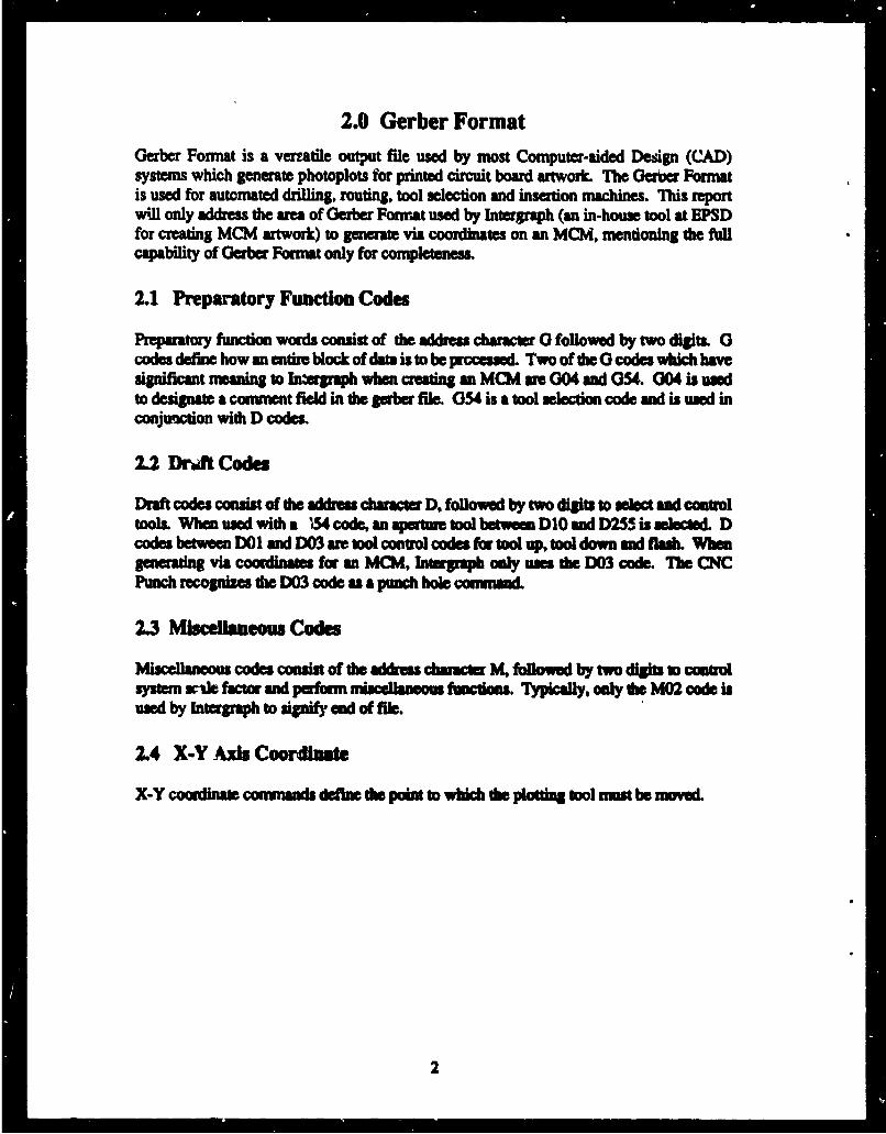
1. A i•LYu ,, .v 2. REPORT DATE 3. ;APORT TYPE AND DATES MOVEREDAugust 1994 Technical Report
4. TITLE AND SuITlI S. FUNDING NUMBERSGERBER FORMAT TO CNC PUNCH TRANSLATOR C: DAAL01-92-C-0226
IL AUTMOF49
Kenneth J. Keyes*
7.PIOMGORGANIZATIO =AM(S) AND ADDRISS(IS) L. PUPORMIG ORGANIZATIOUS Army Research Laboratory (ARL) REPORT NUUiR
Electronics and Power Sources Directorate (EPSD) ARL-TR-418ATTN: AMSRL-EP-IFort Monmouth, NJ 07703-5601
L spsOTOAMrMG AWN NAMIEs) AND ADM•SOES) 10. S SORINGoMOWITONG"AIGNCY REPONT NUMWR
11. SUPPLEMENTARY NOTES
*Kenneth J. Keyes (Vitronics, Inc., 15 Meridian Rd. Eatontown, NJ 07724) performedthis study at the Army Research Laboratory for the project coordinator, Dr. MichaelDukes, of the Electronics and Power Sources Directorate.-
Approved for public release; distribution is unlimited.
I L ASSI1UCT (Maxkwm 200 wo d4
Application specific translators provide an efficient means of converting the outputof an engineering software package to match the input of another engineering softwarepackage; thus, enabling an automated conversion between engineering software pack-ages. In this report, one such'application of a translator which ýrovides a vehicleto program a CNC Punch Machine (an automated hole punching machine) from a GerberFormat File (a standard format for PCB artwork photoplottlng) is presented. Sucha translator, called the Gerber Format to CNC Punch Machine Translator, aids in thedesign of low temperature co-fired (LTCC) Multi-Chip Modules (MCIs). The GerberFormat to CNC Punch Machine Translator enables the MCM designer to program the CNCPunch Machine to punch via holes, using the same Gerber file which is used to photo-plot the MCM signal traces. In doing so, a mechanical engineering package whichwould normally be used to program the CNC Punch Machine is completely eliminatedfrom the f4CM design process.
14. suSuXC TIMs 15. NWIUER Of PAWComputer automated engineering; multichip module; automated 23micropunch; translator; Gerber format I M OR
17. SEICIIRY CASSWICATION UL 5ECUMTV CLAUSSIAT• 15. SECUI' CASSMICA1OU 2L0. UMITATIONO ABSTRACIOF REPORT OF TsIS PAGE OF AUTRACTUnclassified Unclassified Unclassified UL
4.0 Trhnsla-dng Ouber Fw.ma to CNC Punh INUmt...............................
4.1 The Gaber to CNC Pwobh Tlasw P .-nnnnnnnnnnn-...... ....... . ..5
5.0 Example of an M Deaig ........n...... ...............--------ee-...... .135.1 "raasating to tie IDlemiditS Form. ---.. --.-.........--..... . ..... .135.2 CQeadng the CNC Pnech Ple ........................................
1.0 IntroductionThe Electronics and Power Sources Directomie (EPSD) of the Army Research Laboratoryhas in-house capability of prototyping miniaturized systems based on Multi-chip Modules(MCMs) using a low temperature co-fired ceramic (L.TCC) process. A machine used in theProcess of makcing LTCC MCMs is the CNC Punch Machine (an automated hole punchingmachine). The CNC Punch is used to puznch holes for the vias (a feed-thru which connectssignal traces on different layers) in the MCM4. Previousy, the CNC Punch Machine hadto be programnmed manually. The X and Y coordinates for each via hole to be punched hadto be entered by hand from the keyboard. This proved to be rather tedious for larg MCMdesigns with several vins anid multiple holesis
In this Odchical, report, a vehicle which autmates the geeraimon of X and Y coordinatesfor holes punched by the CNC Punch Machine hi presented. Such n vehidcl is a miaslatorfrom Ger~ Word Format to CNC Punch Machinie File fomat (developed at theEle~'tonics and Powe Source Directorate of die Army Resarch Laboratory). The Gerberto 04C Punch Trinailaar reads a gerber file (a standard format for PCB artwork
poolouins) and seuieraes; files of X and Y coordinafts which ame used to program theCNC Punch Machine. Mw smuantc of the Gere= ForMt and dhe CNC Punch MachineFile format will be discussed. Second, the supa involved in translating a gertber file to aCNC Punch Machine file will be discussed. Finally an exanple of an MCM desig ispruented, frm bejainnlg to and.
2.0 Gerber FormatGerber Format is a verratile, output fie used by most Computer-aided Design (CAD)systems which generate photoplots, for printed circuit board artwork. The Gerber Formatis used for automated drilling, routing, tool selection and insertion machines. This reportwill only address the are of GebrFormat used by Intergraph (an in-house tool at EPSDfor creating MCM artwork) to generate via coordinates on an MCM, mentioning the fullcapability of erber Format only forcopens.
2.1 Preparatory Function Codes
Prepartory function words consist of the address character 0 followed by two digits. 0codes define how an entire block of data is to be processed. Two of the 0 codes which havesignificant meaning to In=ergaph when creating an MCM wre 004 and 054. 004 is uwedto designate a comment field in the gerber file. 054 is a tool selcton code and is used inconjuniction with D codes.
2.2 Druft Codes
Draft codes consis of the address character D, followed by two digits to select: and conudltools. When used with a 154 code, an aperture tool between DID mad D255 is selecled. Dcodes between DOI and D03 are tool contro codes for tool up, tool down and flash. Whengenerating via coondinates for ma MCM, Intergiraph only use the D03 code. The CNCPunch recognize the D03 code as a punch hole comnmand.
2.3 Miscellaneous Codes
Miselaneuscodes consist of the address chawmcer KMflowed by two digits to canbusystem unle factor and perform miscellaneous functions. Typically, only die MM2 code isused by Intergraph to signify end f file.
2.4 X..Y Axis Coordinate
X-Y coordinate conunands deine the point to which die plotting tool must be moved.
2
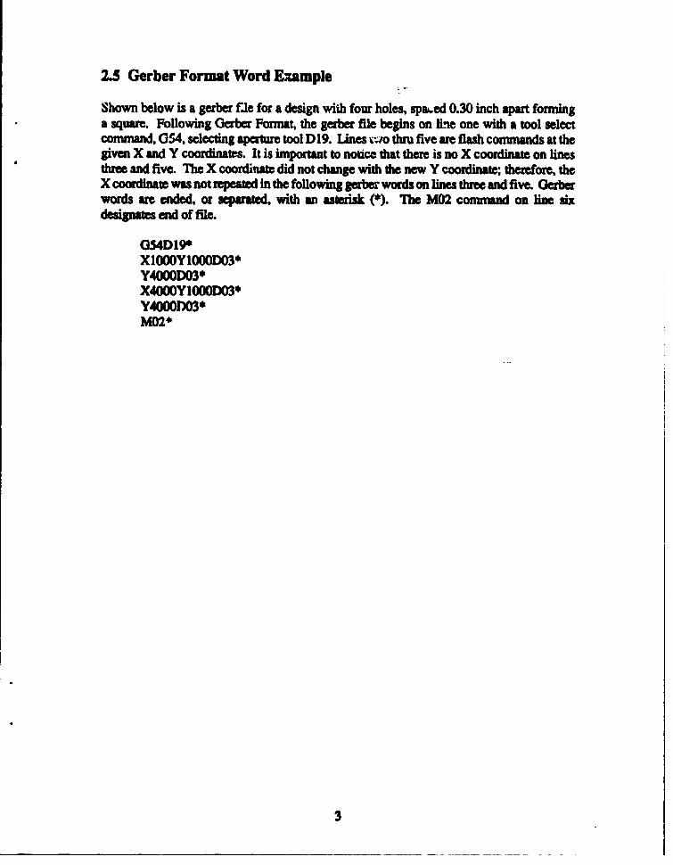
2.5 Gerber Format Word Example
Shown below is a gerber fle for a design with four holes, spa6ed 0.30 inch apart forminga square. Following Gerber Format, the gerber file begins on Ime one with a tool selectcommand, 054, selecting aperture tool D19. Lines two thru five are flash commands at thegiven X and Y coordinates. It is important to notice that theme is no X coordinate on linesthree and five. The X coordinate did not change with the new Y coordinate; th•rdefore, theX coordinate was not repeated in the following gerbea words on lines three and five. Gerberwords are ended, or separated, with an asterisk (*). The M02 command on line sixdesignates end of file.
3.0 CNC Punch Machine FormatThe CNC Punch is an automated machine for punching holes in a piece of material. Up tofour differnt sized punch tools can be loaded at a time, requiring four sets of X and Ycoordinates, before having to retool the machine with new sized punches. Hole punchingis done in blocks, the punch machine completes punching all of the coordinates of a blockbefore selecting the next punch tool. A block of X and Y coordinates can be eithermanually entered in at the keyboard or loaded from ASCII files which are grouped by holesize. Based from a progrmmable orig, the CNC punch machine punches holes atcoordinates given in absolute mode and in inches. There ar tree options for entering apattern definition: as an X-Y coordinate, as a line, and as an area. This report will onlyaddress the X-Y coordinate definition, since this is the mode used at EPSD.
3.1 X-Y Coordinate Pattern
The X-Y coordinat method is the simplest way to program a pat for the CNC Punch,achint. A block of X ad Y coordinates is created in the format shown below. Thepattern is lliH e to 3800 hole for each Wock Finally, den nmust be a pamat block ofX and Y coornaes for wc s hle o be pacmd.
x Y
+0.0000 -0.0000 Wnn vakcs in inchs+9.9999-9.9999 1hbbnwm values tn -che
The firstcbm acter in ch coum must be cd + r - slit
The secood daacr can be my ule beIween 0 md 9.
Thle third character as always a dechimal point.
Th four dig o dorl of do decimal up m be anynumber to 0000 to 9999. The auftn equlus that all towdiits be F Md, VMf fth u all wo'a
The"X" coordinat is always followed by a spe, then the"Y" coordinate i.prsen in the sarne u af s doth
4
4.0 Translating Gerber Format to CNC Punch FormatA rule-based language, Prolog, is used to completely write the Gerber to CNC PunchTranslator. Based on the first character of each control word in the gerber file, a series ofProlog rules arm executed to map the control word into a Prolog intermnediate form. Uponcompletion of reading the gerber file, the intermediate file is then parsed. As such, Prologmapping rules are constructed to transform the intermediate form into a series of files inCNC Punch format. The files created are files of X and Y coordinates representing blocksof via holes to be punched.
4.1 The Gerber to CNC Punch Translator Program
A runtime entry point is provided. This is done so that a stand-alone program can becreated. The definition of a stand-alone program is a Prolog program that can be executedindependent of the Prolog Development System. In essence, a run time system is createdwhich can be distributed to a system that does not host the Prolog Development System.
runtlmeoentry(start) :- st.
The Gerber to CNC Punch Machine Translator program starts with the rule stM. The useris prompted to enter in the name of the gerber file. Note that single quotations must be putaround the entered file name. When Prolog reads an entry from the keyboard, it treats thetext input as a Prolog atom. File names with an extension (.ext) can potentially causeproblems for Prolog because of the significance of the period. In Prolog the period is usedto designate the end of a rule, or series of rules, or the end of input. By placing single quotesaround the filename, it will force Prolog to recognize file names, with ".ext", as an atom,thus enabling Prolog to open the gerber file for reading. This section also opens a Prologintermediate file which aids in the translation of Gerber to CNC Punch format.
st:-write('[ Enter the gerber file with extension to be tramslated 1'),Di,write(s[ surrounded by single quotatiohs followed by a "." ]'),Bi,wrilte('[ example "file.at". ]'),hi,read(Flena-me),uee(Fllmane),tell(gerberint),tranmjrber(O).
These following two Prolog rules signal the translator to either continue on or to close thegerber input file and to jump down to the next phase of the translator. If continuing on, thetranmator reads the Sesemr file character by character and uses the rule lnterpt..char/1 to
5
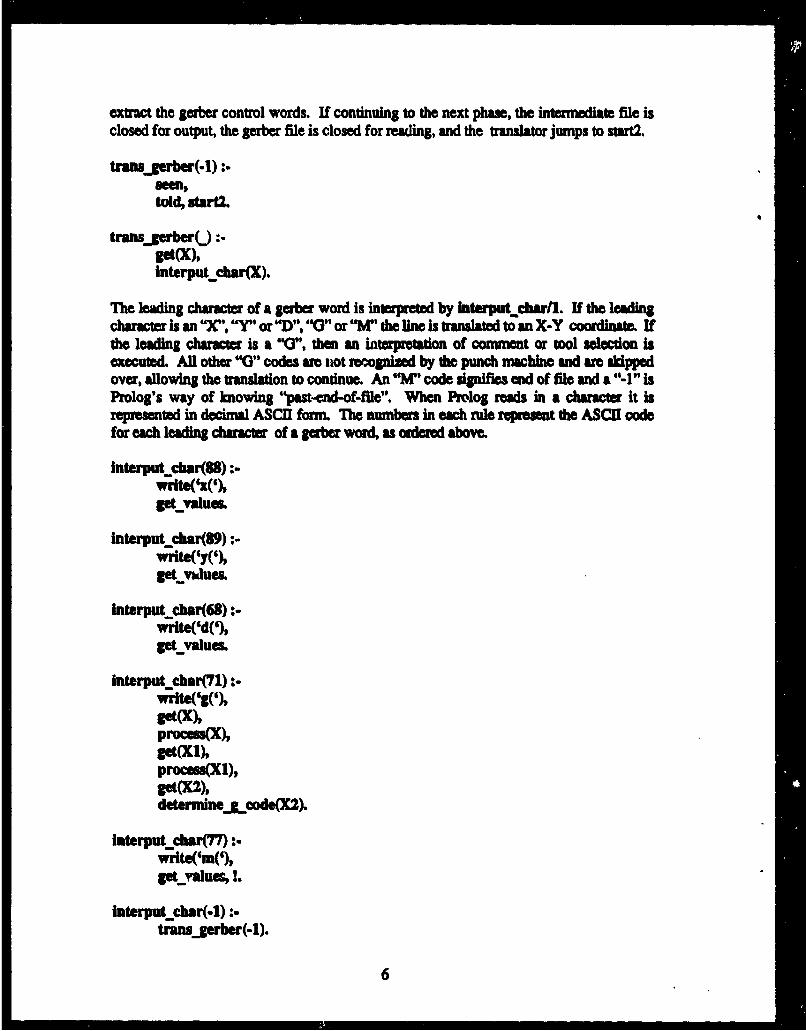
extract the gerber control words. If continuing to the next phase, the intermedae file isclosed for output, the gerber file is closed for readling, and the tranlator jumps to start2.
transgerber(.1) :
told. utarti.
trans.JerberU :-
interputchar(X.
The leading character of a gerber word is interpreted by interpu~tcbarl. If the leadingchaacter is an 'X", "Y"or'"D,V'O"or "M" the lminIs translated to an X-Y coordinate. Ifthe leading character is a 'V", then an interprstation of comnment or tool selection isexecuted. All other "0"codes amc not recognized by the punch machin and ame ikppedover, allowing the translation to continue An 'M'code signifies end of file and &'"-1" isProlog's way of knowing "pas-end-of-file". When Prolog reads in a characte it isrepresented in decimal ASCII form. The numbers In each rule reprsent the ASCII codefor each leading character of a gerber word, as ordered above.
The Prolog rule determlnej~code/1 is called by interputchr/l to continue extractingthe "'a" code from fth gerber file. Based on the rules below, the current character in thegerber word is determined to be either a "D" or an asterisk (*). If the current charater is a"D", 1D" code being representative of an aperture tool selection, a cour~a is written to theintermnediate file. Thm translator then moves on to extract the aperture tool from the gerberfile. If the current character is an asterlsk, representing end of gerber word, the translatorendL mapping the gerber word in the intermediate form and moves on to extract the nextgSaber word from the gerber file.
If the "0" code was determined to be a commnent (004), then the characters in the commventfield are read until the end of gerber word charater (*) is detected. All characters in acomment field are disregarded, for commnents arn not transltatd. The following ruleenables the translator to continue on when comment fields exist in a gerber Mie,
determlnej~code( X) :
determunlegjcode(X).
After a determination of the leading character of a new gerber word (e.g., XYD,0 )isdone, the remaining characters of the gerber word are read in and tanslated to theintermediate file in Prolog format. A Ptolog structure is created for each gSaber word.
get values:.get(X)process(X)ge values.
The following Prolog rules, proeeua/1. recognize the ASCII code in decimal for thenumbers 0 thru 9 and the letters 'W", -Y", "DU' and -0". When Prolog perfdrms ageicharacter, get(X), the character is represented in its ASCII decimal form.
write('x(').
process(89) :-
7
write(
proces(45) :--
procu(48) :-
procm(49) :-write(G1').
promn(SO) :-write('2').
procua(51) :-writeC13').
procus(1) :-'write('49).
promWS(3) :-wrlte('5'l).
procu.(S4) :-writteC6').
procsas() :-wriIte7').
procuu(56):-wrlte('8').
procm(87) :-write('r9).
ASCII code in decimal for & "D".
procmu(68):-
ASCII Code in decimal for "
procmu(42) :-
tranajeber(O).
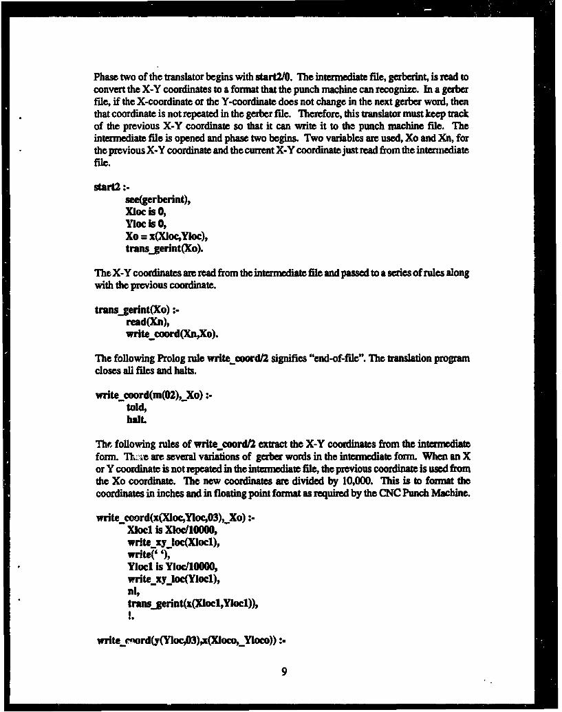
Phase two of th e translator begins with start2/O. The intermnediate file, gerberint is read toconvert the X-Y coordinates to a format that the punch machine can recognize. In a gerberfile, if the X-coordinate or the Y-coordinate does not change in the next gerber word, thenthat coordinate is not repeated in the gerber file. Therefore, this translator must keep taukof the previous X-Y coordinate so that it can write it to the punch machine file. Theintermediate file is opened and phase two begins. Two variables arm used, Xo and Xn, forthe previous X-Y coordinate and the current X-Y coordinate just read from the intemedilatefile.
The X-Y coordinates are read from the intermediate file and passed to a series of rules alongwith the previous coordinate.
trans..gerint(Xo) :read(Xn),write coord(XnXo).
The following Prolog rule write cord/2 signifies "end-of-file". The translation programcloses all fies and halts.
write coord(m(O2),_Xo) :toldhaiL
11r. following rules of write coord/2 extract the X-Y coordinates from the intemdiateform. Th. .%-Iare several variations of gerber words in the intermediate form. When an Xor Y coordinate is not repeated in the intennediate Mie, the previous coordinate is used fromthe Xo coordinate. The new coordinates are divided by 10,000. This is to formnat thecoordinates in inches and in floating point format as required by the CNC Punch Machine.
write coord(x(Xloc,,Yloc.03),_Xo) :X~ocl hs Xloc/10000,write xyjoc(XIocl),write(' '),YloCl Is YIoc/lOOOO,wnite-xyylocYIoc),ni,tra=_gerint(x(XIocl,,YIocl)),
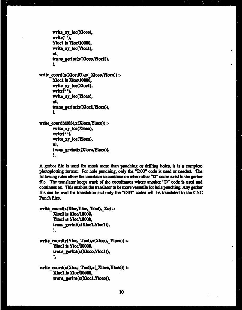
.wriedor(xO3)~xcpO)x(ocoYloco)) :XIOCl is Xmoc/10000write yloc(XOCl)wnite(' '1),wrlteýXyloc(Yoco),niptrans~gernt(x(XIocl,Yloco))p
write coord(d(03)gx(Xloco,Ylow)) :
WrlteyLocXl-0COCO),write( '),WrltGexyloc(YOc),
tramsjerint(x(XlocopYkoco))p
A gerber file is used for much nmor than punching or drillng holes, it is a completephotoplotting format. For hole punching, only the "D03" code is used or needed. Thefollowing rules allow the transator to continue on when other TD" codes efit in the gerberfile. The translator keeps track of the coordinates wvhere another "D)" code is used andcontinues on. This enables the translatorý to be more versatile for hole punching. Any gerberfile can be read for transation and only the "DOT' codes will be translted to the CNCPunch files.
write-coord(x(Xloc,,YlocooI), Xo) :X1o01 bs Xloc/1000W,Y1ocl is YlOC/100U,0transjgerint(x(XIoc1,YIoc1)),
v~teuiord(x(X~o.,TooI),xC XfoeopYkoo)) :XIOCl h. XIOC/100000tramhgeln*~(XboCl,YIoc))p
10
!.
write coord(d(Tool),Xo) :.transgerint(Xo),
write coord(x(XlocYnoc),_Xo) :.XIocl is XIoc/10000,Ylocl is YIoc/10000,tramnjerint(x(XIocl,Ylocl)),
write coord(x(Xloc),(_XCloYYoco)) :.Xlocl is XIoc/10000,transgerint(x(Xlocl,Yloco)),I.
write coord(Ay1oc),x(lom,_Y0co)) :.Yioci is YIoc/lOM)O,trann gerint(x(Xkoos,Yiocl)),0I
A select tool command 054 is detected he The ranslator closes the previous file of X-Y coordinates and opens a new file for the next block ofcoordinates. Th user is promptedfor file names and how the filename should be entered. Single quotes around the file nameare necessary because of the significance of the period to Prolog. Piolog uses the, period toend a rule or series of rules. A filename with an ".ext" violates Prolog's use of the period.Putting single quotes around the fileame turns the filenane into an atom which Prolog canuse.
write coord(g(54,Tool),Xo) :-told, tell(tuer),write('[ Enter the file name for the tool d'),write(ToOl),write(', "file.at". ]'),nl,
When a "G" code other than 054 is encountered, the translator skips over the "O"code inthe inteminediate file and continues on. A 054 code is the only "0" code that hassignificac to the CNC Punch Machine.
III
write coord(gzXo) :-trans_gerint(Xo),
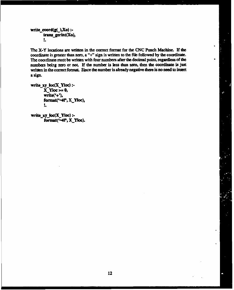
The X-Y locations are written in the correct format for the CNC Punch Machine. If thecoordinate i3 greater than zero, a "+" sign is written to the file followed by the coordinate.The cooidinate must be written with four numbers after the decimal point, regardless of thenumbers behag zero ox not. If the number is less than zero, then the coordinate is justwritten in the correct format. Since the number is ahready negative there is no need to inserta sign.
5.0 Example of an MCM DesignPresented here is an example of the Gerber Format to CNC Punch Translator being used toaid in the making of an MC. Shown in Figure lA is an MCM design with four vias,spaced 0.30 inch apart from each other in a square fashion. The origin of this particularMCM is in the lower left comer, with the X-Y coordinate (0,0). Shown in Figure 1B is thegerber file which was generated, by Intergraph, to photoplot the MCM artwork Typicallyhere at EPSD, the Intergraph CAD system is used as the first step in making an MCM. Thesignal rae and vias are drawn in Intergraph and a gerber file is generated forphotoploning the artwork.
5.1 Translating to the Intermediate Form
Translation from Gerber Format to a CNC Punch Machine file is begun by executing thetranslator with the command "gerberdtrans". Upon execution, the user is prompted for thename of the gerber file and as to how the filename should be entered. Upon entering thefilename, the translator begins mapping the gerber file into a Prolog intermediate form.Each gerber word in the gerber file is represented in the intermediate form as a Prologstructure which is used by phale two of the translator. Shown in Figure 1C is theintermediate file for the MCM design.
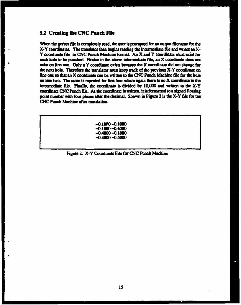
When the gerber file is completely mad, the user is rompte for an output file nam for theX-Y coordinates. The uuaator then begins reading the inmedia fEde and writes an X-Y coordinaft file In CNC Punch M hine forma An X and Y coordinat must ist foreach hole to be punched. Notice in the above inamedia fllm an X coordinate does notexist on line two. Only a Y coordinate exists becaus the X coordinate did not change forthe n•t hole Therefore th translator must keep rack of the previous X-Y omdimnt onlin one so that an X coordinate can be written to the CNC Punch Machine file for the holeon lie two. The same is repeated for line four whe again them is no X coordiam in the
tmedi file. Fuafly, die cooinaft is divided by 10,000 and mitten to the X-Ycoordinate CNC Pmch file. As the coordina is write ft is fonnatted to a signed floatingpoint number with four places afr dtheo dmL Shown in Figure 2 is the X-Y file for theCNC Punch Machine after translation.
In designing the Gerber to CNC Punch Translato, the process of pog die CNCPunch Machine is now fully automnated. Previously, a user had to progam the X and Ycomrdinats for each hole to be punched by hand. Now a gerber file, which is a smtnardforma for photplotft and used by most CAD ystem, is easily used to prosam dtCNC Punch Machine. Given that the translator is designed to read any gerber file,formatmd in absolute mode and in inches, it is not necessal strip out the gober controlwords, from the garber fi which do not pertain to hole punching. The Geabe Format toCNC Punch Translatm simply extracts the via coordinams from the geVrbe file andgaenet an X-Y coordinate file. Thus, a gerber file which was created to photoplot anMCM deWsn including signal "m as well as via locations, is readily usable to progrnthe CNC Punch Machin
ARMY RESEARCH LABORATORYELECTRONICS MID POWER SOURCES DIRECTORATE June 1994
CONTRACT OR IN-HOUSE TECHNICAL REPORT Page 1 of 2MANDATORY DISTRIBUTION LIST
Defense Technical Information Center* Commander, CECOMATTN: DTIC-OCC R&D Technical LibraryCameron Station (Bldg S) Fort Monmouth, NJ 07703-5703 .Alexandria, VA 22304-6145 1) ASEL-IM-BN-I-L-R (Tech Library)(*Note: Two copies will be sent from 3 ANSEL-IN-B-I-L-R (STINFO ofc)
TI O office, Fort Nomouth, NJ)
DirectorUS Arm Material Systems Analysis ActvATTN: DRXSY-NP
(1) Aberdeen Proving Ground, 141 21005
Comander, AMCATTN: ANMC-SCS001 Eisenhower Ave.
(1) Alexandria, VA 22333-0001
DirectorArw Research LaboratoryATTN: AMSRL-D (John W. Lyons)2800 Powder Nill Road
(1) Adelphit PO 207M3-1145
DirectorArn Research LaboratoryATTN: MISRL-00 (COL William J. MIller)2300 Powder Nill Road
(1) Adelphi, ND 207I3-1145
DirectorArmy Research Laboratory2800 Powder Il I BuadAdelphi, NO 20783-1145Iii •ISRL-OP-CI-AD (Tech Pubs)