Getting ready to make that first flight? Making sure you are ready. Here are a few things which may be helpful. This page is definitely a work in progress and more will be added as time goes on. I'm looking for related information from guys that have built and are now flying their Q-craft. If you have comments you would like to pass on, please e-mail me. Are you getting ready to fly? Maybe you're in the the taxi stage? Use all the resources available to you to make your first flight(s) safe and successful. I don't suppose I have to tell you that YOU are going to become a test pilot. • Use other builders/flyers as a resource. Probably a hundred Quickie variations have flown by now and chances are there's a builder/flyer somewhere near you. Find out who those people are, through the Quickie Builders Association , and invite them out to look at your project. ( It wouldn't hurt to buy them lunch and some gas). A person who has built and flown their own Quickie plane should be able to help guide you as to what is good and what might need to be changed in your aircraft. It would also be good to have this person taxi your aircraft, looking for any unusual characteristics. • Look at other aircraft, both experimental and certified. As we all know, the Quickie Aircraft Company plans left much to be desired. It would be worth your while to see a Cessna C-150 engine installation. It will give you a better look at the proper way to hook up the throttle, mixture, fuel lines, and cooling baffles.
Transcript
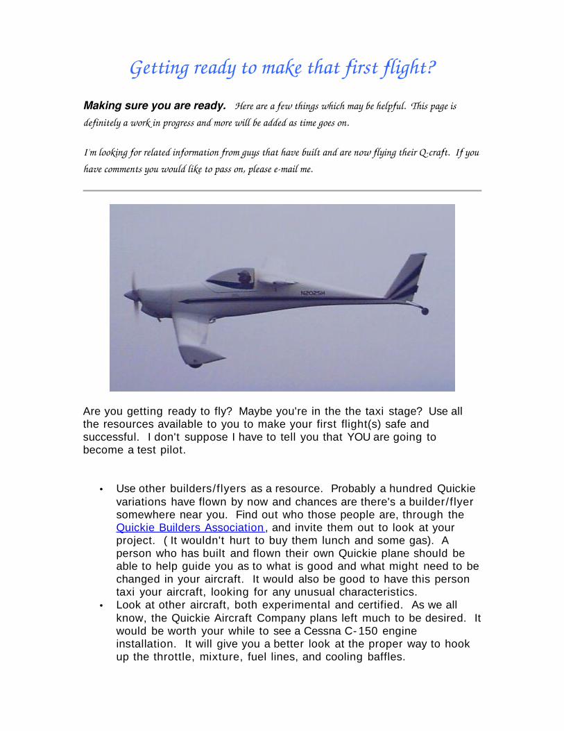
Getting ready to make that first flight?
Making sure you are ready. Here are a few things which may be helpful. This page is definitely a work in progress and more will be added as time goes on.
I'm looking for related information from guys that have built and are now flying their Qcraft. If you have comments you would like to pass on, please email me.
Are you getting ready to fly? Maybe you're in the the taxi stage? Use all the resources available to you to make your first flight(s) safe and successful. I don't suppose I have to tell you that YOU are going to become a test pilot.
• Use other builders/flyers as a resource. Probably a hundred Quickie variations have flown by now and chances are there's a builder/f lyer somewhere near you. Find out who those people are, through the Quickie Builders Association , and invite them out to look at your project. ( It wouldn't hurt to buy them lunch and some gas). A person who has built and flown their own Quickie plane should be able to help guide you as to what is good and what might need to be changed in your aircraft. It would also be good to have this person taxi your aircraft, looking for any unusual characteristics.
• Look at other aircraft, both experimental and certified. As we all know, the Quickie Aircraft Company plans left much to be desired. It would be worth your while to see a Cessna C- 150 engine installation. It will give you a better look at the proper way to hook up the throttle, mixture, fuel lines, and cooling baffles.
• Use checklists. I have developed a comprehensive inspection checklist which may be used to ensure that you haven't overlooked anything. Develop you own flight checklist too and use it.
• Don't be in a hurry.
Is everything in place to make your first flight a safe one? What are the performance numbers for your particular aircraft? Do you know what your minimum level flight speed is? How about your best glide speed? Best speed for minimum decent rate? Best climb? The FAA has an excellent, plain language guide to making that all important first flight and subsequent testing of your aircraft. Advisory Circular AC90- 89a is a 100 page PDF file, so give it time to load.
Another excellent article to determine these numbers is the Bootstrap Approach to Performance
Take a look here how NASA develops their performance numbers.
Want your plane to taxi and nice land straight? Here is the David Gall essay on wheel alignment" .
Better yet, want your plane to stop??!!?? Check out the Larue Brake Mod., complete with drawings.
Are you going to use a Continental O- 200? Here is a nice web site about the engine and some key areas to watch out for. O- 200 goodies.
Here is a Q- 200 Flight Test Evaluation report by Brian Martinez. Shows you how an Air Force test pilot would prepare for his flights. Scott Horowitz published his flight testing work in 1994. It's also filled with "expect the unexpected" tales.
While you're at it, EAA chapter 1000 at Edwards Air Force Base has a bunch of flight test reports . Very interesting reading.
Speaking of test flying, read my friend's account of how he broke the sound barrier in a Luscombe .
The Early YearsThe Quickie Q- 200 is a blast to fly! Here is the story (so far) of my Q-2, N202SH. My kit was serial number 2614 and was purchased in 1981. At the time I felt construction proceeded slowly but in retrospect five years to build now seems fast. This article was originally published in the November 1987 issue of Q- Talk - the mouthpiece of the Quickie Builder's Association. I thought it was worth repeating to describe some of the anxiety that many builders have faced. When the Q- 200 upgrade was announced I decided that it was what I really needed since I wanted to cruise at the advertised 200 mph!
The project was started in Wisconsin and about half way I relocated to the Minneapolis area and moved into Marvin Getten's hanger at Flying Cloud airport. Marv provided a lot of support, help, and guidance, and really helped.
My Q- 200 was equipped with a newly majored engine, vacuum pump, artificial horizon, DG, wing tip strobes, belly board, reflexer, Warnke prop, and originally weighed in at 599 lb. using very accurate scales. I have not yet installed a starter, upholstery, or radios. I estimate total cost to date (1987) of about $22,000.
My previous flight experience consisted of about 500 hours in Cessnas, so before test flying my Q- 200, I got about 10 hours of dual instruction in Citabrias and an hour riding with Marv in his Q- 2 while he shot landings.
Finally, in the Air
After about three hours of taxi testing, the first flight was made on June 9, 1986, with Marv coaching and former Quickie dealer Elliott Youngberg videotaping the happy event!! Over the next couple of weeks I made several flights and did have handling problems resulting in a few ground loops. Also, two of my subsequent flights were made with no airspeed indicator!! It checked out in the shop but in the air it wouldn't work.
Early on it was obvious to see that there was some type of rigging problem, because in order to maintain level flight, I had to fly with my elevators down about 8 degrees. I called Scott Swing, and he said that the angle of incident of my canard was wrong and that I should raise it up!! Well, I could see that there was no other way out, and so I bit the bullet and went to work. I cut the canard free of the fuselage on the two sides and the front, cutting out a wedge- shaped piece. I pulled the engine just far enough to make the cut across the firewall. The front of the canard was raised about 1.25" and repaired. The entire cut- out and repair, including the fillets, moving the rudder pedals, and repainting took one week.
After modifying, in level flight the elevator trimmed at about 1- 2 degrees down. An improvement but I didn't gain any of the airspeed that I'd been hoping for (I was getting about 160 mph).
On one of my flights after this, I landed with the parking brake on and skidded off the runway. It is was my practice to have the parking brake on in flight to prevent wheel spin and the accompanying vibration. I have now added "Parking brake- Off" to my landing checklist and made a change to my in- flight brake system.
Despair
During all of these flights I was constantly tinkering and trimming and adjusting everything, but I just didn't feel that my proficiency was coming up to speed and always felt that I was on the verge of another ground loop. Then, on my 15th flight, on the 29th of July as I was just touching down, the rudder pedal attachment points tore loose, and I was left without any rudder or tail wheel directional control. I was able to keep the wings level, but I was off the runway moving at a high rate of speed. I saw buildings and aircraft coming towards me and I vigorously applied the hand brake. The tail rose up and the prop tore up the rain- soaked ground and the aircraft pole vaulted over using the spinner as the pole!
My beautiful plane came to rest upside down (you can picture this, can't you, Jim?). Besides the spinner and prop being destroyed, the lower cowl was severely damaged, the canopy smashed, and there were compression fractures of the left wing and tail cone and vertical fin. Except for some scratches, the canard was okay. The harness system held, and I was uninjured. I believe that when I repositioned the rudder pedals while changing the angle of incidence of the canard, I didn't have enough of a glass- to- phenolic bond, resulting in failure.
Doubt and Transfiguration
Rebuilding started soon. Even though the wing was only fractured on the bottom just outboard of the aileron pivot and didn't look all that bad, I took the cue from Bob McFarland's accident and resolved to build a new wing. It only took about two hours to remove it from the aircraft. At Oshkosh I was able to pick up a new canopy for only $150, and although I was still heartsick from the accident, things started looking brighter.
After Oshkosh I knew that I had one hell of a lot of preparation in order to even begin repairs, but I had a terrific resource in our local composite chapter 587. I mailed a postcard to each member requesting help, and they came through gangbusters! More than 10 people showed up and in one day we removed the broken canopy and prepared the frame for the new one, sanded the fuselage inside and out to prepare for the wing installation, removed the tail cone fillets and completely removed all paint
and filler from the tail cone, removed paint from the upper and lower cowling, and hot- wired a new set of wing cores and a new vertical fin!! On one Saturday those guys saved me at least a month's work!!
I was able to salvage several parts from the old wing including the ailerons. (Our accomplished crew can now do a wing or canard lay- up in 2.5 hours!) The second time around was easier because I had accomplished all of the tasks before and knew what to do, but it really wasn't very much fun. I only made one significant change in the rebuild. I changed the ground angle of attack of the aircraft to 7.5 degrees by lowering the tail wheel as described by Scott Swing in Quicktalk #29, and this was quite easy to do. Aircraft aesthetics were forgone in order to have the plane back in the air as soon as possible. Ed Schwitzer of New Prauge, MN, let me have a slightly damaged prop that I was able to have repaired to reasonable performance. Paint was only applied as necessary so it doesn't all match right now. However, I was pleased to find that the plane gained only 9 lbs. in the rebuild, and I suspect most of that was from the heavier canopy.
During this time I spent a lot of time thinking about the accident and really questioning my own ability to handle this hot little airplane. When I ordered the kit, I wanted a fairly reliable craft that would be useful for me and not just something to buzz around in on Sunday evenings. I decided as much as I loved the looks of the taildragger, if I didn't feel comfortable with the ground handling problems, I'd convert to Tri- gear, or maybe just sell the whole thing to someone more qualified than I.
After getting another few hours of dual in a Champ, I made my second "first flight" on May 3, 1987, just short of 10 months after the accident. I freely admit that I was more scared now than the "first" first flight. I could feel improvements in the aircraft right away! My takeoff roll increased slightly, but the ground handling was very much improved, which I attribute to the change in the ground angle of attack. This is going to be okay!
Now, five weeks after my second "first flight," I love my airplane. It is a real joy to fly! I have put on 50 hours in the last month and have made over 40 landings and no ground loops! I am getting quite comfortable with crosswind landings and have even landed on a 25' wide runway with
crosswinds. This plane is going to remain a taildragger. The fuel economy is good although I'm still cruising at "only" 160 mph. I've made several cross country flights, and it really eats up the sectional charts.
The plane, like a house, is never finished. I'm still having problems with engine cooling on the 80 degree days and have a lot of experimenting with baffling to do. The whole thing needs to be repainted and upholstery installed, and I have a new Warnke prop ordered. I'm still using a handheld radio (which the tower controllers hate) and navigate using landmarks only. All this is just as well, for it if was finished, I might wind up doing something silly like ordering a new kit of some sort and building something else instead of continuing to improve mine.
My general advice to builders has mostly been said before in Quicktalk, and Jim Masal gave some of the most realistic advice in Q- Talk #3 and #4. First, this is one hot little airplane. It is not docile (at least mine isn't). You must be on top of it at all times, and don't expect anything else. If you feel that you may not be capable of handling it, get some dual with an instructor in something tricky and see how he feels. This is often a hard thing to call, but please be realistic with yourself. You can fool yourself and you can fool your friends, but you can't fool Mother Nature.
On building an airplane.... The most important single thing that a builder must do is to keep his hands on the project. Sound obvious? There were many, many times where I was discouraged and felt, What's the use? Keep at it. Do something, no matter how small, all the time. Also, when you have a seemingly major modification or repair to make, just jump in and get started. Don't waste time worrying about the size of the task ahead. You'll often find that it wasn't as hard or time consuming as you thought once you finally get started. A guy that needs to change his ground angle of attack could have most of the work done in a single day!
Again, as Jim has said, don't build or fly in isolation. By now there are lots of people that may be able to help you. Use the people resources available and have other people help and often. The chances are that by now someone else has had your problem and came up with some sort of solution. Stay in touch with other builders. I had some non- flying buddies help with finish sanding, and they helped save weeks of time.
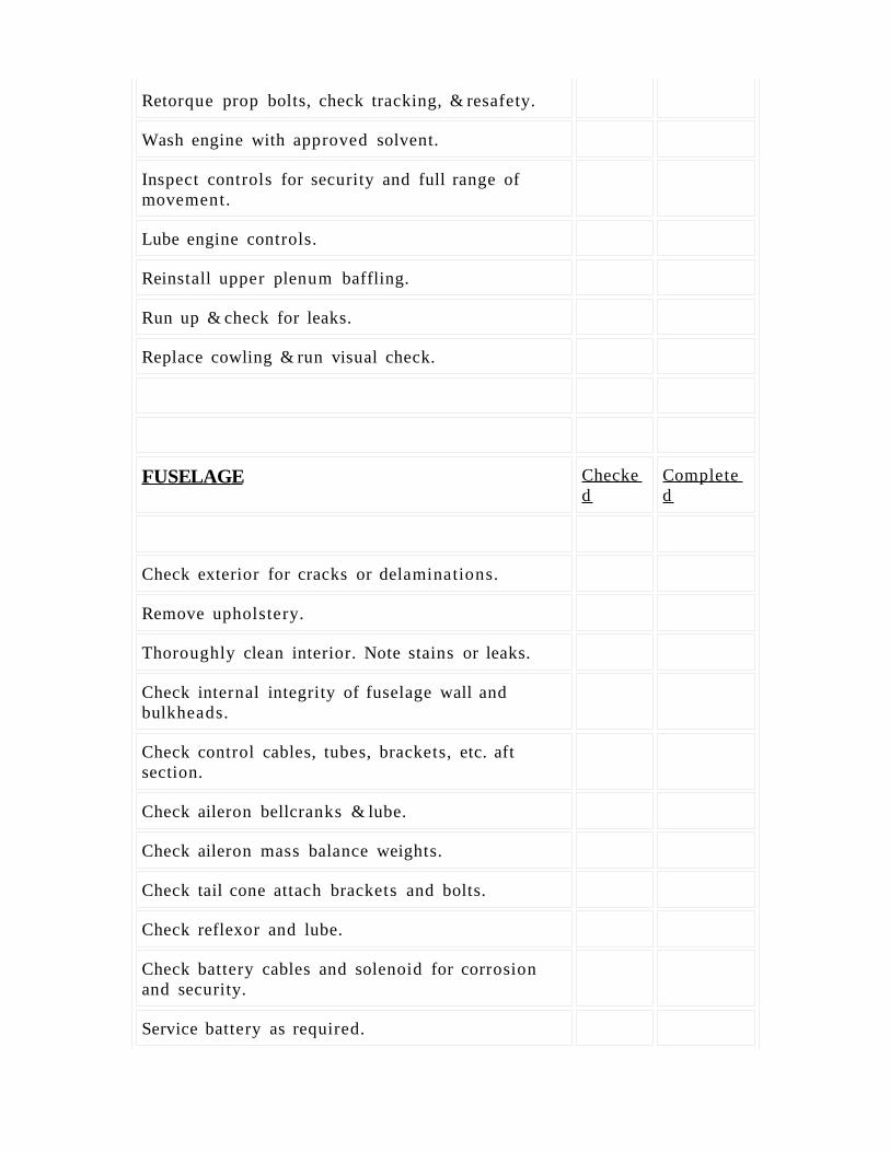
Inspection Checklist
This checklist may be used to perform a final inspection prior to a first flight, and for your annual condition inspection. It is designed for a Q- 200 with conventional gear, one Light Speed Engineering electronic ignition module, and plenum baffling, but may be easily adapted for other Quickies. Plenty of room is available for additional entries to suit your aircraft. This list does not tell you how to qualify a component for safe flight. It is simply designed to ensure that you inspect everything on your aircraft. HOW TO USE THIS CHECKLIST Print out this copy take it out to the airport. Notice there are two columns after each item. When you begin to inspect any certain item, place your initials (or date) in the first column. This establishes what has been inspected, but not necessarily corrected. Generally, you should try to complete the inspection prior to correcting squawks. If there is a discrepancy that needs to be corrected, make a note of it on a separate sheet of paper. When all discrepancies for that particular item have been corrected, and you are completely confident that the component is ready to go and completely airworthy, then place your initials in the second box. This will help you sort out what needs to be inspected, what needs to be corrected, and what is ready to go. Any suggested improvements to this checklist would be welcome.
Home
Q- 200 Annual Inspection / Condition Inspection
N# _____________________ Model ___________________________
The following presents a series of related thoughts on a topic. It is not sufficiently well organized to constitute an article, nor is it even structured adequately to be called an essay. It is not crafted so as to persuade or inform, merely to record my thoughts and convey the basis for that thinking. I have no training or background as an engineer, formal or informal, and no experience with the designs I discuss except that I have read every issue of QuickTalk/Q-Talk, every issue of the QAC newsletter, the complete Quickie and Q-2 plans, and various other articles that have appeared in Sport Aviation and
elsewhere. I have not built an airplane, but I own a Quickie kit that has almost no work done yet. Anyone who incorporates ideas presented herein or in any way alters their intentions or behavior as a result of the ideas presented herein does so at their own risk and by continuing to read beyond this paragraph does implicitly absolve me of any liability or responsibility for any outcome of such actions, desirable or otherwise. I intend to incorporate such ideas as are presented here in my own efforts to build airplanes, therefore this constitutes nothing more than my own personal notes, shared with others for the sole purpose of informing them of my intentions and reasoning. None of the ideas presented here are new or proprietary; rather, the exposure to this particular audience may be new. No attempt is made to overcome the inertia this group has developed as a result of their indoctrination in certain other techniques claimed to benefit in the same manner as these ideas. In other words: don't argue with me, I'm not trying to persuade you; and don't sue me, my net worth is negative!
That said, . . .
BACKGROUND QUOTES
From Nov./Dec. 1985 QuickTalk issue #24, p. 10:
"From Mike Dwyer #2841
"My new canard was measured for flex mounted in a complete airframe, no engine or fuel. Placing 130 lbs. on the wing flexed it 0.6" and 250 lbs. flexed it 1.2". I estimate that with fuel, people, engine etc. it will flex 3" downward. Tires accounted for about 29% of the flex."
From Nov./Dec. 1987 Q-Talk issue #6, p. 7:
"Q-2 TIPS
"Bob Malechek here in Dallas has been exercising his analytical mind and tinkering ability to try to figure out and overcome some of his Q-200's mysterious handling qualities. He's beginning to feel his plane handles now more like a trike than a taildragger (and it's not a Tri-gear). Some thoughts on tires: Bob built his pants to fit the McCreary 5.00x5's but switched to Lamb's saving 3" diameter and 4 lbs. He noticed the McCreary's have a rounded tread contact with the ground whereas the Lamb was flatter. More stable? He found the Lamb was balanced better than the McC. With the diameter decrease, he moved his axles 1.25" forward of the LS-1 plans callout. While he was at it, he put a normal load in the cockpit and then set his wheel to contact the ground vertically (no camber) and straight down the runway (no toe). After 12 landings, he believes something among these changes was significantly better. With his soft tailwheel and 70+ hrs. in the bird now, he may need to install a small TV to keep from falling asleep after touchdown. More from Malechek as testing continues."
From Mar./Apr. 1988 Q-Talk issue #8, p. 10:
"Dear Jim:"My Q-200 taxied squirrley [sic]. Ran off the runway twice slowly uncontrolled. When I changed the axles to steel I noticed that with full weight on the wheels that you no longer were looking 2" forward of the opposite axle IAW QAC plans. I was looking at the ground due to the
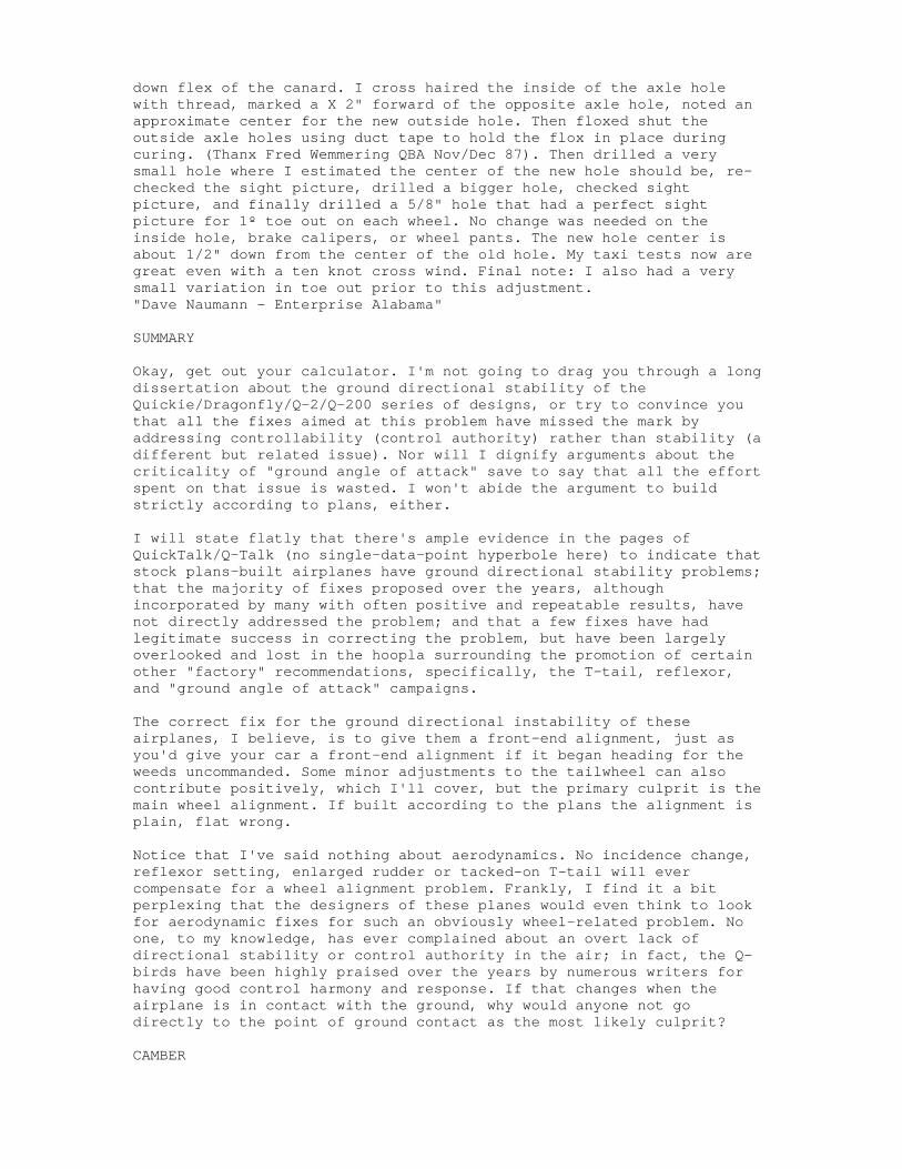
down flex of the canard. I cross haired the inside of the axle hole with thread, marked a X 2" forward of the opposite axle hole, noted an approximate center for the new outside hole. Then floxed shut the outside axle holes using duct tape to hold the flox in place during curing. (Thanx Fred Wemmering QBA Nov/Dec 87). Then drilled a very small hole where I estimated the center of the new hole should be, re-checked the sight picture, drilled a bigger hole, checked sight picture, and finally drilled a 5/8" hole that had a perfect sight picture for 1º toe out on each wheel. No change was needed on the inside hole, brake calipers, or wheel pants. The new hole center is about 1/2" down from the center of the old hole. My taxi tests now are great even with a ten knot cross wind. Final note: I also had a very small variation in toe out prior to this adjustment."Dave Naumann - Enterprise Alabama"
SUMMARY
Okay, get out your calculator. I'm not going to drag you through a long dissertation about the ground directional stability of the Quickie/Dragonfly/Q-2/Q-200 series of designs, or try to convince you that all the fixes aimed at this problem have missed the mark by addressing controllability (control authority) rather than stability (a different but related issue). Nor will I dignify arguments about the criticality of "ground angle of attack" save to say that all the effort spent on that issue is wasted. I won't abide the argument to build strictly according to plans, either.
I will state flatly that there's ample evidence in the pages of QuickTalk/Q-Talk (no single-data-point hyperbole here) to indicate that stock plans-built airplanes have ground directional stability problems; that the majority of fixes proposed over the years, although incorporated by many with often positive and repeatable results, have not directly addressed the problem; and that a few fixes have had legitimate success in correcting the problem, but have been largely overlooked and lost in the hoopla surrounding the promotion of certain other "factory" recommendations, specifically, the T-tail, reflexor, and "ground angle of attack" campaigns.
The correct fix for the ground directional instability of these airplanes, I believe, is to give them a front-end alignment, just as you'd give your car a front-end alignment if it began heading for the weeds uncommanded. Some minor adjustments to the tailwheel can also contribute positively, which I'll cover, but the primary culprit is the main wheel alignment. If built according to the plans the alignment is plain, flat wrong.
Notice that I've said nothing about aerodynamics. No incidence change, reflexor setting, enlarged rudder or tacked-on T-tail will ever compensate for a wheel alignment problem. Frankly, I find it a bit perplexing that the designers of these planes would even think to look for aerodynamic fixes for such an obviously wheel-related problem. No one, to my knowledge, has ever complained about an overt lack of directional stability or control authority in the air; in fact, the Q-birds have been highly praised over the years by numerous writers for having good control harmony and response. If that changes when the airplane is in contact with the ground, why would anyone not go directly to the point of ground contact as the most likely culprit?
CAMBER
Granted, there's been much discussion over the years about wheel alignment on Q-birds. For the most part it has centered on toe-in vs. toe-out, with toe-out emerging as the apparent winner. However, there's more to wheel alignment than just toe. Equally important is camber, a tiny little word you'll find mentioned in the second quotation above about Bob Malechek's airplane. Unfortunately, Bob has at least two more reports in subsequent issues wherein he correctly credits his toe-out and tailwheel mods as significant contributors to his improved handling, but he fails to also mention camber. Perhaps he did not recognize the significance of this factor in correcting his airplane's directional instability.
On the subject of camber, from "Race Car Vehicle Dynamics" by Milliken and Milliken, published by SAE International, p. 46:
"In accordance with SAE terminology.... The camber is positive if the wheel leans outward at the top relative to the vehicle, or negative if it leans inward.
"In racing circles, tilt of a wheel is universally referred to as 'camber', with the sign conventions following SAE as above. The effect of camber on the tire forces and moments actually depends on the angle between the tire and a perpendicular to the ground—as opposed to the angle between the tire and a chassis reference....
"In general, a cambered rolling pneumatic-tired wheel produces a lateral force in the direction of the tilt. When this force occurs at zero slip angle, it is referred to as 'camber thrust'."
Under the heading of 'Alignment' on page 726 of the same book appears the following:
"Camber angle to the road surface is one of the fundamental variables that determine tire performance....
"Camber also works like steer: When a tire is cambered it tends to pull the car in the same direction in which the top of the tire is leaning. A simple way to think about this is camber-steer force equivalence.... For bias-ply tires... 1.0º of camber is equivalent to about 0.2º of steer (5:1). From this simple rule of thumb, it can be seen that static negative camber will require toe-out to keep the wheels from fighting each other."
Keep that last reference firmly in mind as you build your Q-bird, and as you consider the remainder of this treatise.
ALIGNMENT
Also appearing under 'Alignment':
"The amount of static toe on the front will depend on other suspension parameters such as... ride and roll steer, compliance steer..., and camber (both static and dynamic with ride and roll motion). Minimum static toe is desirable to reduce rolling resistance and unnecessary tire heating/wear that will be caused by the tires working against each other."
Wait a minute: what's this "ride and roll steer, compliance steer"
stuff? Well that's the change in steering angle, camber, and toe as a result of the geometry of the axle as the suspension moves through its range of travel. Of note to us is the fact that the camber and toe can be affected absent the steering links of a steerable axle. On the Q-birds the flexibility of the canard in both bending and twist conspire to aggravate the built-in inboard (negative) camber (of a plans-built plane) and to initiate inboard toe as the load on each wheel increases. What does all this mean? Consider for a moment....
FORCE ANALYSIS - INSTABILITY
Our baseline airplane will be a stock, plans-built Q-200. When this plane rolls down the runway, the built-in inboard camber and almost neutral toe allow the main gear tires to generate forces, each inboard toward the center of the airplane, that oppose one another. Another tire characteristic described in the literature is that of generated forces being generally proportional to the load on the tire, so the forces on the left and right gears balance.
Now consider a crosswind gust from the left: the airplane is "heeled" over to the right slightly due to the new side forces on it. This increases the load on the right main tire and decreases the load on the left main tire. The changed loads allow the canard to flex differently, bending and twisting more on the right and relaxing on the left. The right main tire generates more inboard force due to the increased load on it, but more, the inboard camber and toe are increased due to canard flex, amplifying the effect. At the left canard tip the opposite conditions prevail, and the reduced inboard forces of the left main tire are further attenuated by the geometry moving toward a more 0-0 camber-toe setting. The additive resultant of the two front tires' forces is a strong force to the left, just as though the airplane had been equipped with steering and the driver had turned the wheel to the left.
But wait, there's more! This force to the left acts just like steering, so the plane starts to head for the weeds to the left. This is called a turn, and, as any turn, it generates centrifugal force. Since the turn is to the left, the centrifugal force acts to the right, but more importantly, it acts through the Center of Gravity (CG) of the airplane which is somewhere above the surface of the runway. The tires' resultant force acts at the runway surface to the left and the centrifugal force acts at the CG to the right; the resultant rolling couple tends to roll or "heel" the airplane to the right -- in this case, further to the right than the initiating crosswind had already heeled it. So the airplane's response to the initial disturbance is such as to amplify the initial disturbance; this is a textbook definition of instability.
CONTROL RESPONSE - REVERSAL
Hold on, now, we're almost done with this part, but first we've got to consider the pilot's role in all this. After all, it's not the machine but the man/machine entity which must be stable to be useful. When the crosswind first hits, the plane veers to the left. What is the pilot's reaction? How about a good bootful of right rudder, that ought to do it. The Q-bird's tailwheel swings to the right -- wait! Which way does the Q-bird's >tail< go when this happens? To the left, of course. We can go out to the hangar and see this without even opening the canopy. Good.
After the tailwheel is displaced to the right, the tailwheel, impotent though its reputation may be, does generate some force to the left... acting at the surface of the runway... below the CG... creating a rolling couple to the right... ARRGHH!! Our tiny tailwheel, in attempting to alleviate the veer to the left, has actually exacerbated the situation and further propelled us to certain doom! (If you don't see that, re-read the two preceding paragraphs.) Naturally, being pilots, we're going to apply even more right rudder with even more deleterious results. It's no wonder the tailwheel has a reputation for being ineffective and "skidding" just when we need it most.
As a side note, consider the effect of the ailerons on the front-end geometry of these planes as I've described here and you'll have an understanding of how the mysterious "reverse aileron steering" works. By all accounts, this phenomenon is quite positive and reliable, if initially slightly awkward, but, oddly, Mike Dwyer and others with corrected front-end geometry report that the effect is not nearly as pronounced as others would have them believe. Hmmm. Class project: explain why that is.
EXAMPLES
Okay. I think that's enough analysis.
Quoted above are three QBA reports which should not be ignored. At the Sun-N-Fun QBA forum this year (1997) Mike Dwyer stood and announced proudly and convincingly that his Q-bird is probably built closer to the plans than anybody's, even Gene Sheehan's, which I do not dispute. He reported over 870 hours of operation, and strongly advocated following the plans. With his quote from 1985 (above) in mind, I asked him about the stance of his landing gear at gross weight. He confirmed that he had adjusted his main gear for zero camber at gross weight. I think from now on I'll consider Mr. Dwyer's airplane to be the baseline against which all others should be measured, pending his consent, as there is no factory standard against which to compare.
Between Dwyer, Malechek, and Naumann, we have three Q-birds reporting significantly better than stock ground handling. No mention of "ground angle-of-attack," reflexors, T-tails, or bigger rudders. Malechek says he moved his axles forward 1.25 inches and has a "soft" tailwheel; in other reports to Q-Talk he also mentions tailwheel centering springs. These, too, contribute to directional stability and control authority, but the meager control authority of the tailwheel will never rival the power of the destabilizing forces that the main wheels can generate when misaligned as they are if built in accordance with the plans.
CRITICAL SPEED
Page 174 of "Race Car Vehicle Dynamics" introduces Significant Speeds:
"...Maurice Olley was the first to discover the critical speed beyond which some vehicles become divergently unstable."
Continuing on page 177:
"At the 'critical speed' the car becomes divergent, that is, a small steering input results in very large (theoretically infinite) responses in terms of path curvature, yawing velocity, lateral acceleration, or
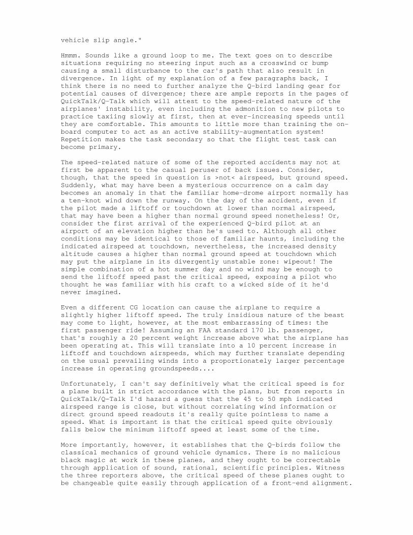
vehicle slip angle."
Hmmm. Sounds like a ground loop to me. The text goes on to describe situations requiring no steering input such as a crosswind or bump causing a small disturbance to the car's path that also result in divergence. In light of my explanation of a few paragraphs back, I think there is no need to further analyze the Q-bird landing gear for potential causes of divergence; there are ample reports in the pages of QuickTalk/Q-Talk which will attest to the speed-related nature of the airplanes' instability, even including the admonition to new pilots to practice taxiing slowly at first, then at ever-increasing speeds until they are comfortable. This amounts to little more than training the on-board computer to act as an active stability-augmentation system! Repetition makes the task secondary so that the flight test task can become primary.
The speed-related nature of some of the reported accidents may not at first be apparent to the casual peruser of back issues. Consider, though, that the speed in question is >not< airspeed, but ground speed. Suddenly, what may have been a mysterious occurrence on a calm day becomes an anomaly in that the familiar home-drome airport normally has a ten-knot wind down the runway. On the day of the accident, even if the pilot made a liftoff or touchdown at lower than normal airspeed, that may have been a higher than normal ground speed nonetheless! Or, consider the first arrival of the experienced Q-bird pilot at an airport of an elevation higher than he's used to. Although all other conditions may be identical to those of familiar haunts, including the indicated airspeed at touchdown, nevertheless, the increased density altitude causes a higher than normal ground speed at touchdown which may put the airplane in its divergently unstable zone: wipeout! The simple combination of a hot summer day and no wind may be enough to send the liftoff speed past the critical speed, exposing a pilot who thought he was familiar with his craft to a wicked side of it he'd never imagined.
Even a different CG location can cause the airplane to require a slightly higher liftoff speed. The truly insidious nature of the beast may come to light, however, at the most embarrassing of times: the first passenger ride! Assuming an FAA standard 170 lb. passenger, that's roughly a 20 percent weight increase above what the airplane has been operating at. This will translate into a 10 percent increase in liftoff and touchdown airspeeds, which may further translate depending on the usual prevailing winds into a proportionately larger percentage increase in operating groundspeeds....
Unfortunately, I can't say definitively what the critical speed is for a plane built in strict accordance with the plans, but from reports in QuickTalk/Q-Talk I'd hazard a guess that the 45 to 50 mph indicated airspeed range is close, but without correlating wind information or direct ground speed readouts it's really quite pointless to name a speed. What is important is that the critical speed quite obviously falls below the minimum liftoff speed at least some of the time.
More importantly, however, it establishes that the Q-birds follow the classical mechanics of ground vehicle dynamics. There is no malicious black magic at work in these planes, and they ought to be correctable through application of sound, rational, scientific principles. Witness the three reporters above, the critical speed of these planes ought to be changeable quite easily through application of a front-end alignment.
APPLICATION
"Race Car Vehicle Dynamics," page 24:
"The peak of the [tire lateral thrust] curve may remain at a constant value or fall off slowly as indicated [chart]. In dry conditions, race tires generally reach their peak lateral force at slip angles in the vicinity of 3º-7º. On a wet surface the peak will in general be lower, and the fall-off in lateral force after the peak will be more rapid."
What does this tell us? It tells us that those who advocate 2º of toe out to tame the Q-birds are using up the available tire lateral force range to a significant degree just to make the airplane reasonably docile, indicating that the tiger whose tail they've grabbed is a strong one, indeed. It also tells us that, since peak tire lateral thrust is similar to the load carried by that tire, the lateral forces are large causing great heat and wear on the tires. A quick estimate for a 1000 lb. Q-200 might be that each main tire is carrying 450 lbs. while the tailwheel carries 100 lb. Extrapolating, the tire lateral forces during straight rolling at speed may be as much as 300 lbs. But wait, that 300 lbs. is not occurring on those airplanes with toe out for the toe out somewhat alleviates the inboard loads built in to those airplanes when they were stock; rather, the stock airplanes built strictly to the plans without camber or toe out mods are experiencing high inboard lateral thrust loads on the main gear.
Significantly, the main gear lateral thrust loads substantially exceed the thrust that the tailwheel can generate, and, as has already been shown, brisk application of steering inputs to the tailwheel can actually adversely increase the lateral thrust of the main tires. Is it any wonder, then, that the tailwheel gets described as ineffective?
NUMBERS
Okay, back to the calculator. Using Mr. Dwyer's numbers from the quote at the opening of this harangue, it becomes readily apparent that the spring rate of the canard is about one-half inch per hundred pounds. Pretty convenient! So, with a 1000 lb. gross weight we can estimate that 900 lbs. are carried by the canard resulting in about four-and-a-half inches of canard sag. Since the span is 200 inches and both wing tips respond equally to the loading, we can figure the angle of deflection using the sag over the semispan: Arctan(4.5" / 100") = 2.58º. So the wing bends under gross weight load in such a way that the anhedral is reduced by 2 x 2.58º = 5.16º or about five degrees. Structures texts tell us that a uniform beam loaded at its ends will exhibit a tip deflection twice the overall deflection, in other words, our main gear tires will lean inboard about five degrees each, maybe a little more since the canard is a tapered beam, not uniform.
As a check, Mr. Naumann (quoted above) reports that his "new hole center is about 1/2" down from the center of the old hole." Given the stock axle length of 7.25 inches, the hole offset for 5º of tip deflection works out to 7.25" x sin 5º = .63 inches, within tolerance, I believe, of the referenced 'about 1/2"'. Further, note that Mr. Naumann retained 1º of toe out (under load) which compensates for insufficient camber of about 1/5º ("camber-steer force equivalence" quoted above from Race Car Vehicle Dynamics) yielding 7.25" x sin 4.8º
= .60 inch. Finally, Mr. Naumann does not relate the weight he used other than to say "full weight" and there's always the inevitable builder tolerances to consider. Using his 1/2 inch number and the axle length of 7.25 inches gives arctan(.5" / 7.25") = 3.95º, so we agree within one degree as to the amount of built in "bad" camber that the plans give us if we follow them.
I'm going to continue using the 5º number for several reasons, not least of which is that many builders are now flying using a 1100 lb. gross weight. Also, my goal is not to just reduce the instability inherently built into these planes, but to go past neutral and into the positive stability area. I want a plane that doesn't just accept benignly, but one that counteracts actively the effects of bumps and gusts and such. I want a no-workload ride. Too, there are dynamic effects encountered in crosswinds and tailwheel steering inputs and bumps and aileron inputs, etc., which will serve to flex the canard more than just the gross weight condition; I want a camber margin on the "good" side of neutral that can absorb these small excursions. And, to reduce tire wear, I want this all without having to resort to outboard camber as Mr. Naumann did. (Did I mention that 'crowning' of the runway also has a negative effect on the angular relationship between the tire and the pavement surface?)
Using 5º as the final tip deflection and the amount of inboard camber that a stock, plans built Q-bird needs to have removed, there are things that can be done in construction of the airplane to effectively "pre-load" this spring that is the canard. Working backward, again, with Mr. Naumann's numbers, and using the technique called for in the plans of sighting across to the other wheel pant to establish the toe and camber, we find that the aiming point for the sight picture must be 192" x sin 3.95º = 13.2 inches(!) up from the opposite wheel pant's axle hole. Using the 5º that I advocate yields 192" x sin 5º = 16.75 inches. Wow. That's a bit more than the 5.5 inches I've seen advocated elsewhere, but I have always questioned the genesis of that number as nothing more than a number pulled from a hat. However, 16.75 inches up from the axle hole would be a challenging place on which to sight, so perhaps during construction a stick could be bondo'd to the wing center section and a point about 9 inches up from the plane of the axles used as the aiming point. Be careful, too, that in construction 'up' is closer to the surface of the earth since the canard is built inverted.
Just for fun let's see what Mr. Naumann's "looking 2" forward of the opposite axle IAW QAC plans" gives for a built in toe out preload. Arctan(2" / 192") = .6º. The geometry of the canard under load allows some of this toe out to be lost, though I don't have data on how much twist deflection the tip experiences. Assuming that .5º of toe out remains under load and applying the 5:1 camber-steer equivalence gives about 2.5º of camber that may have been compensated for by the factory. Well, it's a start.
So, what can be done for new construction airplanes? Mount the wheel pants with 5º outboard camber and retain the plans-specified toe out setting, I say. For existing planes there may not be enough room in the wheel pant to adjust camber sufficiently; For these, I recommend either cutting away and remounting the wheel pants or choosing a smaller replacement tire (and wheel?) to permit the necessary camber adjustment.
At the very least, follow a procedure similar to that described by Mr.
Naumann to re-align the main gear axles. Be sure to do the procedure at gross weight and to allow the main gear to spread laterally under load so that the full extent of the canard sag may be developed before any new axle holes are drilled.
It's that simple.
TAILWHEEL
I also promised to address some tailwheel considerations. Unfortunately, the data available on tailwheels is not nearly so robust as that available on groundloops. Let me explain.
Certain individuals will rightly advise making no changes to the airplane until having flown it as a "factory stock" item, else where is your baseline for measuring change? Well, I only know of two airplanes that are otherwise stock yet have the front-end alignment correct: Dwyer's and Naumann's (and I'm not really sure that Naumann's qualifies as otherwise stock). However, I can't abide the argument to build stock first, especially when that argument is coupled with the inevitable comment about having only a single data point as a basis on which to initiate modifications. I believe that the names Gene Sheehan and Gary LeGare constitute single data points, yet when they advocated T-tails and Reflexors and "Ground-angle-of-attack" tweaking, everybody jumped on those bandwagons. So, there aren't that many airplanes out there to look at that don't also have a reflexor or such, thus muddying the database on which to judge the effectiveness of tailwheel mods.
Now, there are also those who will argue that I base my front-end alignment argument on a 'single' data point, that of the three builders reports quoted at the head of this diatribe and especially Mr. Dwyer's airplane. Not so. I have myriad data points telling me what does NOT work scattered throughout the pages of QuickTalk/Q-Talk, namely, all the accident reports of stock airplanes that just don't behave, and all the back-and-forth tweaking of the T-tails, reflexor settings, and ever more precise callouts for the bogus "Ground-angle-of-attack" setting that never seems to have been right, in retrospect, after the accident. In short, although I may only have one or two data points on which to stake my claim, I have an entire herd of dead lemmings at the bottom of the "cliff of truth" to attest to the inadequacy or outright failure of all those other single-data-point fixes.
Also, not one external reference has ever been presented (to my knowledge) to lend either theoretical or experimental support to the arguments in favor of the current crop of mods; in fact, there are no arguments in support of increasing the load on the tailwheel, only the contention that 1) it skids, and 2) there isn't much load on it. I believe that I've adequately described above the dynamics of the tailwheel "skid" and it is worth noting that in the above-described scenario any increase in load on the tailwheel only increases the force with which the tailwheel can generate the roll moment that exacerbates the already diverging behavior of the airplane. In short, increasing the load on the tailwheel makes the tailwheel more prone to "skid" and decreases the range of usable rudder pedal force and rate of application that can be used before rudder application becomes the precipitating event that initiates a ground loop. So long as such behavior persists it is moot to try to qualify the differences between tailwheel setups. Also note that the behavior attributed to tailwheel "skid" actually requires an effective tailwheel, whereas if the
tailwheel were truly skidding it would be unable to generate the forces that ultimately put the airplane into the weeds.
This is not to say that certain tailwheel changes can't be said to be helpful. Indeed, the addition of centering springs (as opposed to the in-circuit springs normally used on tail wheel installations to absorb shock) can be shown to be beneficial in both the directionally unstable stock configuration and in the corrected front-end alignment situation that I advocate. In the stock situation the centering springs, as would a locking tailwheel, oppose the rapid yawing of the airplane necessary to ground loop (within the traction limits of the tailwheel), while not generating the adverse roll moment that a rapid or forceful corrective pilot input generates. The springs also oppose pilot inputs, giving more control feel while attenuating the force or speed of control inputs that may otherwise have caused or amplified divergence. Finally, centering springs respond immediately to any deviation of the airplane's heading from its track whereas pilots have reaction times; the centering springs can apply a smaller corrective force sooner than a pilot can, further reducing the risk of creating adverse rolling moments. All of these effects are also beneficial to airplanes with corrected front end geometry. The question then becomes one of necessity: are centering springs necessary once the front end geometry is corrected?
Similar arguments could be made regarding the solid rubber tailwheel supplied in the kit vs. pneumatic tires, but I'll withhold judgment until I've examined a Q-bird built according to "corrected" plans, with adequate precompensation built into the canard to assure that the toe out and, particularly, the camber are both positive when the airplane is loaded to gross weight. I believe, without any justifiable evidence, that the stock tailwheel is adequate to the task, but I may learn otherwise (I hope not the hard way).
SUMMARY
Well, I've probably lost and/or angered somebody with these words. That is not my intent, but is, perhaps, inevitable. I've not edited or rewritten to convince or persuade, only to record. I've shared this with the intent of reporting my own, personal conclusions on this topic, and am open to reasoned, thoughtful rebuttal, but I'm pretty well convinced that I'm not exactly preaching to the choir, either. This is not an exhaustive analysis nor is it a flight test report so is subject to revision, but I believe that it is essentially grounded in the theories of ground vehicle dynamics as presented in the referenced text, which is more than I can say for any 'analysis' presented so far in advocacy of T-tails, reflexors, or "ground angle-of-attack." I recognize that my writing style leaves much to be desired, and to those for whom this became just so much gobbledygook, I apologize.
Just make sure your camber and toe are both positive at gross weight, and enjoy your Q-bird for what it should be!
David J. GallP.O. Box 2624Vero Beach, FL 32961-2624561-569-5885email: [email protected]
It's more than just a "Quickie"!
Mods That I Have MadeIt's a nice design, but... The Q200 is a great little plane, but of course you can hardly build a plane without making some changes. One thing is for certain, the Quickie Aircraft Company (QAC) didn't last too long and their design never had a chance to mature. After flying, it immediately became
apparent there was a need to make some modifications. Other problems demanded attention after flying lots of hours. I am listing some of the more important changes I made and why I made them.
Please keep in mind that these are my opinions only. Other builders may have something that works better. Maybe QAC had a reason for their design that is not readily apparent to me. Anyway, if you do any of these and something goes wrong, don't sue me. They just worked for me.
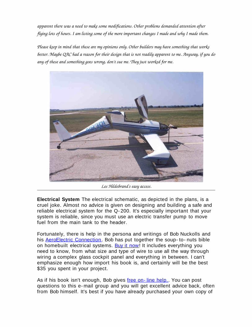
Les Hildebrand's easy access.
Electrical System The electrical schematic, as depicted in the plans, is a cruel joke. Almost no advice is given on designing and building a safe and reliable electrical system for the Q- 200. It's especially important that your system is reliable, since you must use an electric transfer pump to move fuel from the main tank to the header.
Fortunately, there is help in the persona and writings of Bob Nuckolls and his AeroElectric Connection . Bob has put together the soup- to- nuts bible on homebuilt electrical systems. Buy it now! It includes everything you need to know, from what size and type of wire to use all the way through wiring a complex glass cockpit panel and everything in between. I can't emphasize enough how import his book is, and certainly will be the best $35 you spent in your project.
As if his book isn't enough, Bob gives free on- line help. . You can post questions to this e- mail group and you will get excellent advice back, often from Bob himself. It's best if you have already purchased your own copy of
the AeroElectric Connection before posting questions, since many replies will refer you to sections of the book.
Q- 200 Engine Mount Bolt Plates. The plans call for aluminium. Aluminium is too soft and the first ones I had deformed. The thrust of the engine tries to pull the bolt heads through the plate. Make them out of steel.
Fuel Capacity For a cross country aircraft to be useful you need lots of fuel. I have a 16- 1/2 gallon main and a 6- 1/5 gallon header tank. This gives me three hours of flying time, plus an hour in reserve. The Q- 200 plans call for a reduced size header tank so you can have access to the engine mount bolts on the aft side of the firewall. By getting a little creative with the shape of the header tank I was able to retain a larger fuel capacity. This translates to more reserve fuel and more peace of mind.
Fuel Cap Do not use the plastic bottle cap, as supplied by QAC, for a fuel filler cap! The area on the fuselage outside the fuel filler door is low pressure. If the fuel filler cap leaks air, that low pressure enters the mail fuel tank and starves the engine of fuel. This has happened to a couple of guys and it introduced a large pucker factor about 300 feet off the runway. Make a more positive sealing system and make sure it won't break. Here is a photo of mine, which I copied from Jim Doyle. It is simple, cheap, reliable, proven, and parts are avilable at any hardware store. Fuel filler cap.
In general, the QAC fuel system plumbing is amateurish. I reccomend embedding threaded aluminium hard points in the tanks and doing away the floxed- in aluminium tubing. You are better off going to aircraft quality fittings. Use 3/8" fittings, instead of the 1/4" as called out in the plans.
Landing gear axles. Again, the plans called for aluminium. Make a couple of hard landings and they are bent. Make them out of steel, using the same wall thickness.
LaRue Brakes. Acutally, it is a modification to the brake mounting system. Named after Bob Larue, the guy that first installed them on his Q- bird. called for aluminium. The origional mounts were cantankerous and led to uneven braking and severe chattering. This system works a lot better. See it here LaRue brake mount .
Tailspring As soon as guys started completing airplanes, back in the 80's, guys started breaking tailsprings. (Comment from Gene Sheehan: "If guys wouldn't prang their airplanes on landings, they wouldn't break tail springs) I heard about this problem through the grapevine and beefed mine up. I added a couple of extra wraps of BID and UNI. Since this increased the outside diameter of the spring, I also enlarged the tail wheel fitting. This worked well for over an estimated 1,000 landings.
Finally, it broke (which led to making the next two mods). The replacement spring was designed by John tenHave and made by an Australian sailboat spar maker. I think it is quite good. Some post mortems have been performed on the origional QAC fiberglass springs and there is much left to be desired. The Aussies have done a better job of engineering and I am quite pleased with it. If you want one of these, send me an e- mail and I'll get you in touch with them.
Differential Braking . Original plans called for a single master cylinder driving the brakes. A couple of the guys installed differential braking in their Q- 200s and it looked to me like a "nice to have" mod. Sure, it was easy to install (just add a second brake cylinder and lever) and was nice for turning tight corners, but I didn't really think I needed it. That is, until my tail spring finally broke. You see, when you lose tail steering you have no directional control, an undesirable contition. If I had differential braking I might have been able to keep the aircraft on the runway. This leads us to the next mod.
Rudder/tailspring isolation If you build to QAC plans, and you break the tail spring, you lose rudder control. I thought is wouldn't happen to me, but it finally did.
The modification was pretty simple. There is a coupling on the rudder cables where the fuselage splits (origional plans). I simply made a new fitting and added a second cable which now connects to the rudder bellcrank as well as the tail wheel bellcrank. Now, even if the tail spring should break I will still have rudder control. This can also be done using an intermediate bellcrank, as part of the Jim- Bob 6- pack.
Gall Wheel Alignment . The wheel alignment is established by the axle hole through the wheel pants. In the plans, QAC has you install the wheel pants on to the canard, before the canard is mounting on the aircraft. This aircraft has a gross weight of 1,100 lbs. When all that weight is placed on the canard, the wheels splay out and the aligment changes. Drilling the holes should really be accomplished AFTER everything is together. Here is a link to David Gall's extensive essay on the matter. David Gall essay on wheel alignment
The Continental 0- 200 . The 0- 200 isn't really a mod, but since it is not the original Revmaster equipped Q- 2, I just wanted to express my opinion. Keep in mind this is what has worked for me.
I do a lot of cross country flying. I regularly fly over the Ozarks, I've flown over the Rockies a couple of times, and the Appalachians. Landing speed on my aircraft is somewhere around 80 mph so an off- field landing would be very bad news. Reliability is the most important feature of any engine. I see a variety of engines going into Q- craft and all of them are touted to be
greatest thing since sliced bread. That may well be, but I'm sticking with the 0- 200, thank you.
Sure, the Continental costs more, but it is a proven design and parts are available for it all over the country. It is also easy to find mechanics that know a lot about it.
Are you going to use a Continental O- 200? Here is a nice web site about the engine and some key areas to watch out for. O- 200 goodies.
Speed Brake. QAC option. I think it's nice to have.
Reflexor . An aerodynamic trim device that raises or lowers the ailerons. I wouldn't fly without it.
Roll Trim . The roll trim changes throught the flight regime. I added an in-light adjustable turnbuckle to the left elevator torque tube. It works great.
2- into- 1 Exhaust The 4- into- 1 system is a real maintenance pain in the arse. This system makes it a lot easier to change a leaky exhaust gasket.
Aluminium Instrument Panel This simplified return electrical grounds. I didn't like the idea of a wood/glass panel to begin with. Then, I saw QAC's aircraft and noticed THEY had an aluminium one. Mine is .055".