www.cypress.com Document No. 001-77759 Rev. *C 1 AN77759 Getting Started with PSoC ® 5LP Author: Ross M. Fosler Associated Project: Yes Associated Part Family: All PSoC 5LP parts Software Version: PSoC ® Creator™ 3.0 SP2 and higher Related Application Notes: For a complete list of the application notes, click here. To get the latest version of this application note, or the associated code example, please visit http://www.cypress.com/go/AN77759. AN77759 introduces you to PSoC ® 5LP, an ARM ® Cortex ® -M3-based programmable system-on-chip. It helps you explore the PSoC 5LP architecture and development tools and shows you how to create your first project using PSoC Creator™, the development tool for PSoC 5LP. This application note also guides you to more resources to accelerate in-depth learning about PSoC 5LP. Contents Introduction .......................................................................1 PSoC Resources ...............................................................2 PSoC Creator ...............................................................2 Code Examples ............................................................3 PSoC Creator Help.......................................................4 Technical Support ........................................................4 PSoC 5LP Feature Set ......................................................5 PSoC is More Than an MCU .............................................7 My First PSoC 5LP Design................................................8 About The Design.........................................................8 Part 1: Create the Design .............................................8 Part 2: Program the Device ........................................ 15 Summary ......................................................................... 16 Document History............................................................ 17 Worldwide Sales and Design Support ............................. 18 Introduction PSoC 5LP is a true programmable embedded system-on- chip, integrating custom analog and digital peripheral functions, memory, and an ARM Cortex-M3 microcontroller on a single chip. This type of system is different from most mixed-signal embedded systems, which use a combination of a microcontroller unit (MCU) and external analog and digital peripherals, such as opamps, ADCs, and application- specific integrated circuits (ASICs). PSoC 5LP provides a cost-effective alternative to the combination of MCU and external ICs. The PSoC 5LP architecture boosts performance through: 32-bit ARM Cortex-M3 core plus DMA controller and digital filter processor, at up to 80 MHz Ultra-low power with industry's widest voltage range Programmable digital and analog peripherals enable custom functions Flexible routing of any analog or digital peripheral function to any pin PSoC devices employ a highly configurable system-on- chip architecture for embedded control design. They integrate configurable analog and digital circuits, controlled by an on-chip microcontroller. A single PSoC device can integrate as many as 100 digital and analog peripheral functions, reducing design time, board space, power consumption, and system cost while improving system quality.
Transcript
www.cypress.com Document No. 001-77759 Rev. *C 1
AN77759 Getting Started with PSoC® 5LP
Author: Ross M. Fosler Associated Project: Yes Associated Part Family: All PSoC 5LP parts Software Version: PSoC® Creator™ 3.0 SP2 and higher
Related Application Notes: For a complete list of the application notes, click here. To get the latest version of this application note, or the associated code example, please visit http://www.cypress.com/go/AN77759.
AN77759 introduces you to PSoC® 5LP, an ARM® Cortex®-M3-based programmable system-on-chip. It helps you explore the PSoC 5LP architecture and development tools and shows you how to create your first project using PSoC Creator™, the development tool for PSoC 5LP. This application note also guides you to more resources to accelerate in-depth learning about PSoC 5LP.
PSoC Creator ............................................................... 2 Code Examples ............................................................ 3 PSoC Creator Help ....................................................... 4 Technical Support ........................................................ 4
PSoC 5LP Feature Set ...................................................... 5 PSoC is More Than an MCU ............................................. 7 My First PSoC 5LP Design ................................................ 8
About The Design ......................................................... 8 Part 1: Create the Design ............................................. 8 Part 2: Program the Device ........................................ 15
Summary ......................................................................... 16 Document History ............................................................ 17 Worldwide Sales and Design Support ............................. 18
Introduction PSoC 5LP is a true programmable embedded system-on-chip, integrating custom analog and digital peripheral functions, memory, and an ARM Cortex-M3 microcontroller on a single chip.
This type of system is different from most mixed-signal embedded systems, which use a combination of a microcontroller unit (MCU) and external analog and digital peripherals, such as opamps, ADCs, and application-specific integrated circuits (ASICs).
PSoC 5LP provides a cost-effective alternative to the combination of MCU and external ICs. The PSoC 5LP architecture boosts performance through:
32-bit ARM Cortex-M3 core plus DMA controller and digital filter processor, at up to 80 MHz
Ultra-low power with industry's widest voltage range
Programmable digital and analog peripherals enable custom functions
Flexible routing of any analog or digital peripheral function to any pin
PSoC devices employ a highly configurable system-on-chip architecture for embedded control design. They integrate configurable analog and digital circuits, controlled by an on-chip microcontroller. A single PSoC device can integrate as many as 100 digital and analog peripheral functions, reducing design time, board space, power consumption, and system cost while improving system quality.
PSoC Resources Cypress provides a wealth of data at www.cypress.com to help you to select the right PSoC device for your design, and quickly and effectively integrate the device into your design. For a comprehensive list of resources, see KBA86521, How to Design with PSoC 3, PSoC 4, and PSoC 5LP. The following is an abbreviated list for PSoC 5LP:
PSoC 5LP. In addition, PSoC Creator includes a device selection tool.
• Datasheets: Describe and provide electrical specifications for the PSoC 5LP device families
• Application Notes and Code Examples: Cover a broad range of topics, from basic to advanced level. Many of the application notes include code examples. PSoC Creator provides additional code examples – see Code Examples. Recommended application notes for getting started with PSoC 5LP are: • AN61290, Hardware Design Considerations • AN57821, Mixed Signal Circuit Board Layout • AN81623, Digital Design Best Practices • AN73854, Introduction To Bootloaders
• Technical Reference Manuals (TRM): Provide detailed descriptions of the architecture and registers in the PSoC 5LP device family.
• Development Kits: • CY8CKIT-001 provides a common development platform for
any one of the PSoC 1, PSoC 3, PSoC 4, or PSoC 5LP families of devices.
• CY8CKIT-050 is designed for analog performance. It enables you to evaluate, develop and prototype high precision analog, low-power and low-voltage applications powered by PSoC 5LP.
Both kits support the PSoC Expansion Board Kit ecosystem. Expansion kits are available for a number of applications including CapSense, precision temperature measurement, and power supervision.
The MiniProg3 device provides an interface for flash programming and debug.
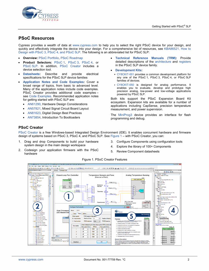
PSoC Creator PSoC Creator is a free Windows-based Integrated Design Environment (IDE). It enables concurrent hardware and firmware design of systems based on PSoC 3, PSoC 4, and PSoC 5LP. See Figure 1 – with PSoC Creator, you can:
1. Drag and drop Components to build your hardware system design in the main design workspace
2. Codesign your application firmware with the PSoC hardware
3. Configure Components using configuration tools 4. Explore the library of 100+ Components 5. Review Component datasheets
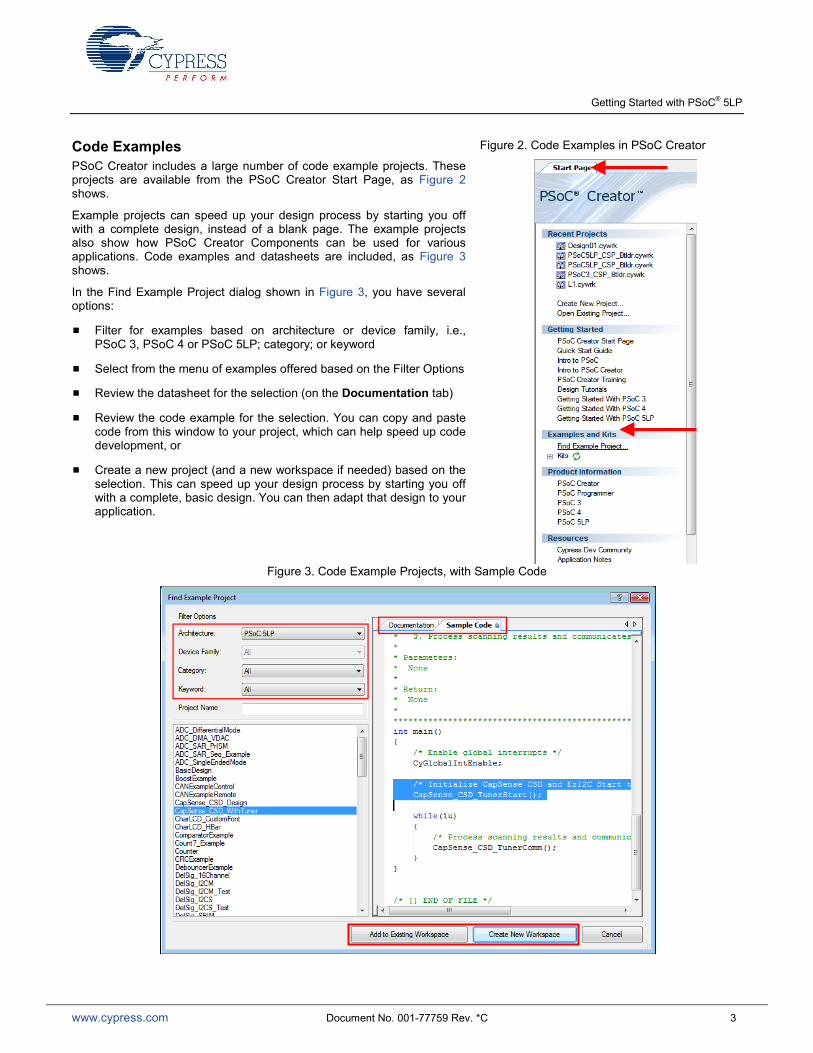
Code Examples PSoC Creator includes a large number of code example projects. These projects are available from the PSoC Creator Start Page, as Figure 2 shows.
Example projects can speed up your design process by starting you off with a complete design, instead of a blank page. The example projects also show how PSoC Creator Components can be used for various applications. Code examples and datasheets are included, as Figure 3 shows.
In the Find Example Project dialog shown in Figure 3, you have several options:
Filter for examples based on architecture or device family, i.e., PSoC 3, PSoC 4 or PSoC 5LP; category; or keyword
Select from the menu of examples offered based on the Filter Options
Review the datasheet for the selection (on the Documentation tab)
Review the code example for the selection. You can copy and paste code from this window to your project, which can help speed up code development, or
Create a new project (and a new workspace if needed) based on the selection. This can speed up your design process by starting you off with a complete, basic design. You can then adapt that design to your application.
PSoC Creator Help Visit the PSoC Creator home page to download the latest version of PSoC Creator. Then, launch PSoC Creator and navigate to the following items:
Quick Start Guide: Choose Help > Documentation > Quick Start Guide. This guide gives you the basics for developing PSoC Creator projects.
Simple Component example projects: Choose File > Open > Example projects. These example projects demonstrate how to configure and use PSoC Creator Components.
Starter designs: Choose File > New > Project > PSoC 5LP Starter Designs. These starter designs demonstrate the unique features of PSoC 5LP.
System Reference Guide: Choose Help > System Reference > System Reference Guide. This guide lists and describes the system functions provided by PSoC Creator.
Component datasheets: Right-click a Component and select “Open Datasheet.” Visit the PSoC 5LP Component Datasheets page for a list of all PSoC 5LP Component datasheets.
Document Manager: PSoC Creator provides a document manager to help you to easily find and review document resources. To open the document manager, choose the menu item Help > Document Manager.
Technical Support If you have any questions, our technical support team is happy to assist you. You can create a support request on the Cypress Technical Support page.
If you are in the United States, you can talk to our technical support team by calling our toll-free number: +1-800-541-4736. Select option 8 at the prompt.
You can also use the following support resources if you need quick assistance.
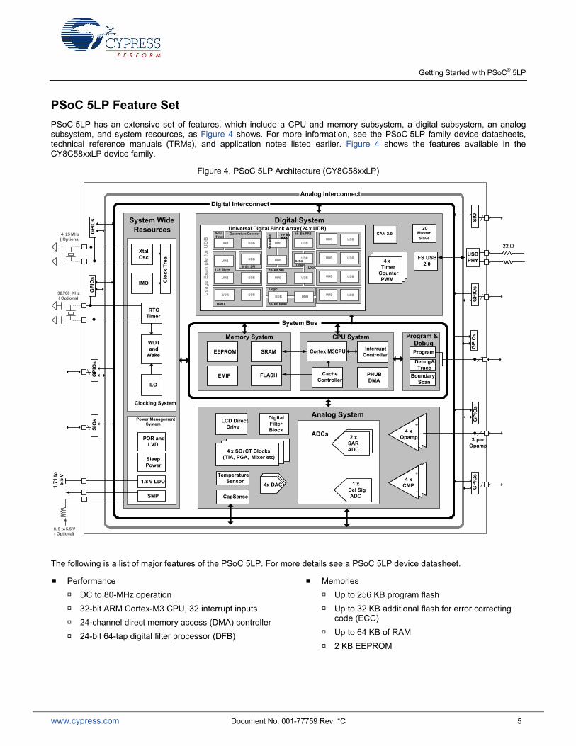
PSoC 5LP Feature Set PSoC 5LP has an extensive set of features, which include a CPU and memory subsystem, a digital subsystem, an analog subsystem, and system resources, as Figure 4 shows. For more information, see the PSoC 5LP family device datasheets, technical reference manuals (TRMs), and application notes listed earlier. Figure 4 shows the features available in the CY8C58xxLP device family.
Figure 4. PSoC 5LP Architecture (CY8C58xxLP)
DigitalFilterBlock
LCD Direct Drive
CapSense
Temperature Sensor
4 x Opamp
+
-
ADCs
4 x DAC 1 x Del Sig ADC
4 x SC/ CT Blocks (TIA, PGA, Mixer etc)
4 x CMP
+
-
Program
Debug & Trace
Boundary Scan
Program & Debug
Cortex M3 CPU Interrupt Controller
PHUBDMA
Cache Controller
SRAM
FLASH
EEPROM
EMIF
Digital InterconnectAnalog Interconnect
1.71
to5.
5V
0. 5 to 5.5 V( Optional)
4- 25 MHz( Optional)
XtalOsc
32.768 KHz( Optional)
RTC Timer
IMO Cloc
k Tr
ee
WDT and
Wake
ILO
Clocking System
1.8 V LDO
SMP
POR andLVD
SleepPower
Power Management System
USB PHY
3 per Opamp
GPI
Os
GPI
Os
GPI
Os
GPI
Os
GPI
Os
GPI
Os
SIO
GPI
Os
SIO
s
2 x SARADC
I2C Master/Slave
Universal Digital Block Array (24 x UDB)
4 xTimer
Counter PWM
FS USB 2.0
UDB
UDB
UDB
UDB
UDB
UDB
UDB UDB UDB
UDB
UDB
UDBUDB UDB UDB
UART
Logic
12- Bit PWM
I 2C Slave8- Bit SPI
12- Bit SPILogic
8- Bit Timer
16- Bit PRS
UDB
8- Bit Timer
Quadrature Decoder 16- Bit PWM
Sequ
ence
r
Usa
ge E
xam
ple
for U
DB UDBUDB
UDBUDB
UDBUDB
UDBUDB
22 Ω
Memory System CPU System
Analog System
System Bus
Digital SystemSystem Wide Resources
CAN 2.0
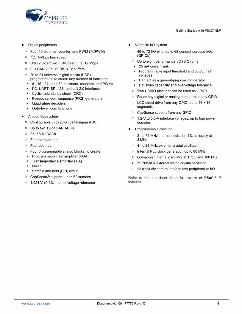
The following is a list of major features of the PSoC 5LP. For more details see a PSoC 5LP device datasheet.
Performance
DC to 80-MHz operation
32-bit ARM Cortex-M3 CPU, 32 interrupt inputs
24-channel direct memory access (DMA) controller
24-bit 64-tap digital filter processor (DFB)
Memories
Up to 256 KB program flash
Up to 32 KB additional flash for error correcting code (ECC)
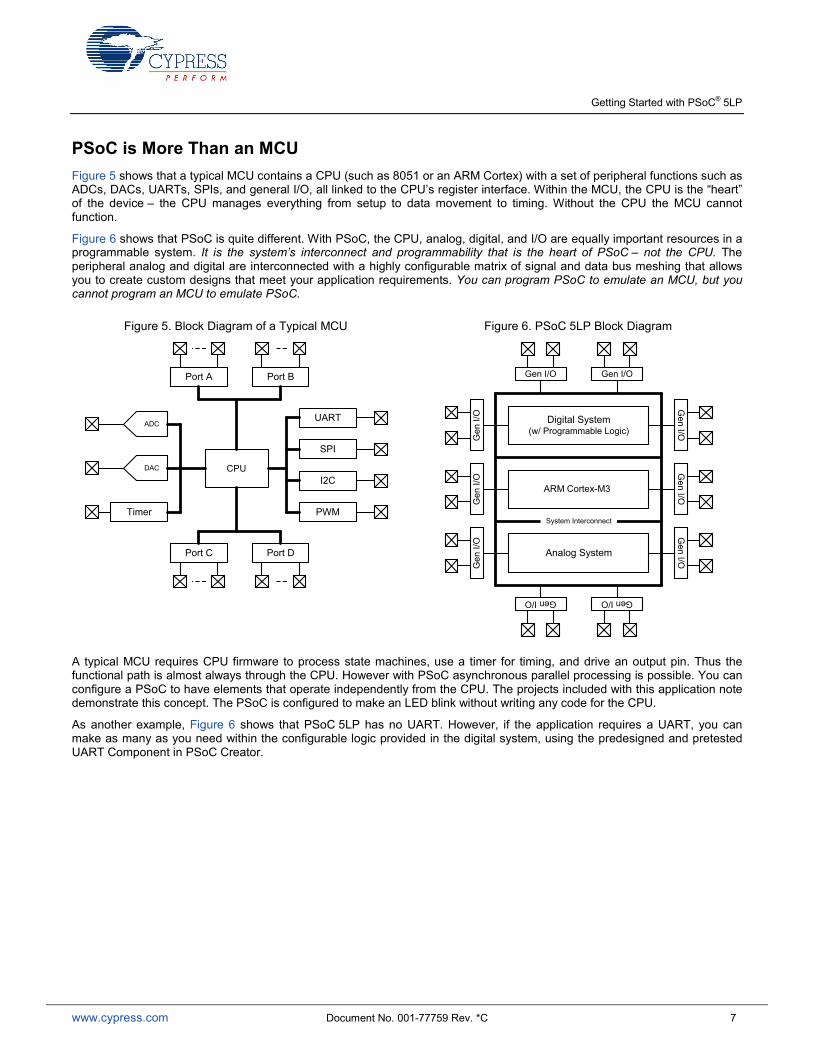
PSoC is More Than an MCU Figure 5 shows that a typical MCU contains a CPU (such as 8051 or an ARM Cortex) with a set of peripheral functions such as ADCs, DACs, UARTs, SPIs, and general I/O, all linked to the CPU’s register interface. Within the MCU, the CPU is the “heart” of the device – the CPU manages everything from setup to data movement to timing. Without the CPU the MCU cannot function.
Figure 6 shows that PSoC is quite different. With PSoC, the CPU, analog, digital, and I/O are equally important resources in a programmable system. It is the system’s interconnect and programmability that is the heart of PSoC – not the CPU. The peripheral analog and digital are interconnected with a highly configurable matrix of signal and data bus meshing that allows you to create custom designs that meet your application requirements. You can program PSoC to emulate an MCU, but you cannot program an MCU to emulate PSoC.
Figure 5. Block Diagram of a Typical MCU
Figure 6. PSoC 5LP Block Diagram
A typical MCU requires CPU firmware to process state machines, use a timer for timing, and drive an output pin. Thus the functional path is almost always through the CPU. However with PSoC asynchronous parallel processing is possible. You can configure a PSoC to have elements that operate independently from the CPU. The projects included with this application note demonstrate this concept. The PSoC is configured to make an LED blink without writing any code for the CPU.
As another example, Figure 6 shows that PSoC 5LP has no UART. However, if the application requires a UART, you can make as many as you need within the configurable logic provided in the digital system, using the predesigned and pretested UART Component in PSoC Creator.
My First PSoC 5LP Design This section does the following:
Demonstrates how PSoC can be programmed to do more than a traditional MCU
Shows how to build a simple PSoC design and install it in a development kit
Provides detailed steps that make it easy to learn PSoC design techniques and how to use the PSoC Creator IDE
Note If you don’t want to go through the design process, you can get the completed PSoC Creator project at http://www.cypress.com/go/AN77759. You can then jump to the Build and Program steps.
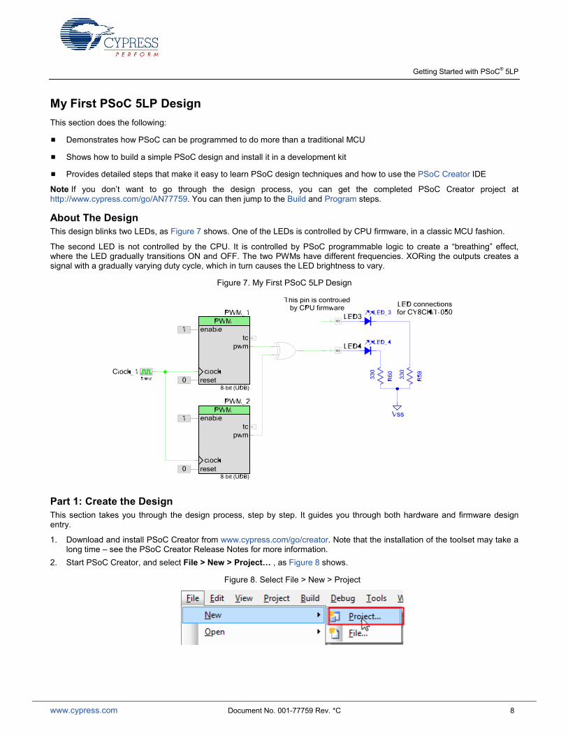
About The Design This design blinks two LEDs, as Figure 7 shows. One of the LEDs is controlled by CPU firmware, in a classic MCU fashion.
The second LED is not controlled by the CPU. It is controlled by PSoC programmable logic to create a “breathing” effect, where the LED gradually transitions ON and OFF. The two PWMs have different frequencies. XORing the outputs creates a signal with a gradually varying duty cycle, which in turn causes the LED brightness to vary.
Figure 7. My First PSoC 5LP Design
Part 1: Create the Design This section takes you through the design process, step by step. It guides you through both hardware and firmware design entry.
1. Download and install PSoC Creator from www.cypress.com/go/creator. Note that the installation of the toolset may take a long time – see the PSoC Creator Release Notes for more information.
2. Start PSoC Creator, and select File > New > Project… , as Figure 8 shows.
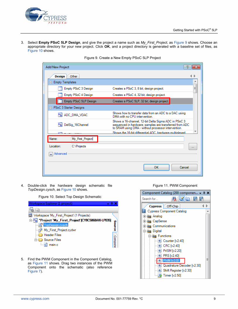
3. Select Empty PSoC 5LP Design, and give the project a name such as My_First_Project, as Figure 9 shows. Choose an appropriate directory for your new project. Click OK, and a project directory is generated with a baseline set of files, as Figure 10 shows.
Figure 9. Create a New Empty PSoC 5LP Project
4. Double-click the hardware design schematic file TopDesign.cysch, as Figure 10 shows.
Figure 10. Select Top Design Schematic
5. Find the PWM Component in the Component Catalog, as Figure 11 shows. Drag two instances of the PWM Component onto the schematic (also reference Figure 7).
6. Double-click each PWM Component to configure it, as Figure 12 shows. Set PWM_1 Period to 254 and CMP Value 1 to 127. Set PWM_2 Period to 252 and CMP Value 1 to 126. This creates a square wave for both PWMs, but with slightly different frequencies. The difference in frequencies results in a beat frequency that can be modulated on the LED.
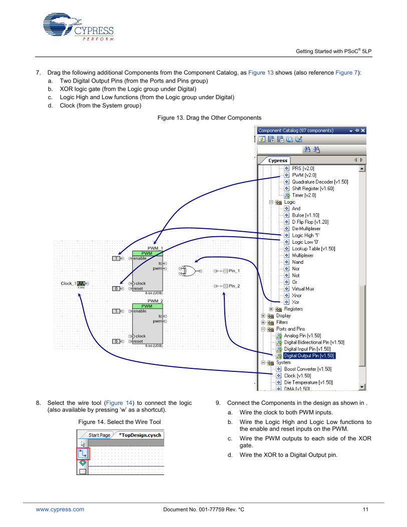
7. Drag the following additional Components from the Component Catalog, as Figure 13 shows (also reference Figure 7): a. Two Digital Output Pins (from the Ports and Pins group) b. XOR logic gate (from the Logic group under Digital) c. Logic High and Low functions (from the Logic group under Digital) d. Clock (from the System group)
Figure 13. Drag the Other Components
8. Select the wire tool (Figure 14) to connect the logic (also available by pressing ‘w’ as a shortcut).
Figure 14. Select the Wire Tool
9. Connect the Components in the design as shown in . a. Wire the clock to both PWM inputs. b. Wire the Logic High and Logic Low functions to
the enable and reset inputs on the PWM. c. Wire the PWM outputs to each side of the XOR
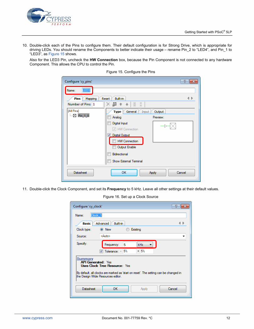
10. Double-click each of the Pins to configure them. Their default configuration is for Strong Drive, which is appropriate for driving LEDs. You should rename the Components to better indicate their usage – rename Pin_2 to “LED4”, and Pin_1 to “LED3”, as Figure 15 shows. Also for the LED3 Pin, uncheck the HW Connection box, because the Pin Component is not connected to any hardware Component. This allows the CPU to control the Pin.
Figure 15. Configure the Pins
11. Double-click the Clock Component, and set its Frequency to 5 kHz. Leave all other settings at their default values.
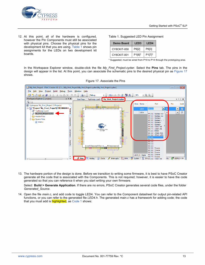
12. At this point, all of the hardware is configured, however the Pin Components must still be associated with physical pins. Choose the physical pins for the development kit that you are using. Table 1 shows pin assignments for the LEDs on two development kit boards.
Table 1. Suggested LED Pin Assignment
Demo Board LED3 LED4
CY8CKIT-050 P6[2] P6[3]
CY8CKIT-001 P1[6]* P1[7]*
* Suggested; must be wired from P19 to P14 through the prototyping area.
In the Workspace Explorer window, double-click the file My_First_Project.cydwr. Select the Pins tab. The pins in the design will appear in the list. At this point, you can associate the schematic pins to the desired physical pin as Figure 17 shows.
Figure 17. Associate the Pins
13. The hardware portion of the design is done. Before we transition to writing some firmware, it is best to have PSoC Creator generate all the code that is associated with the Components. This is not required; however, it is easier to have the code generated so that you can reference it when you start writing your own firmware. Select Build > Generate Application. If there are no errors, PSoC Creator generates several code files, under the folder Generated_Source.
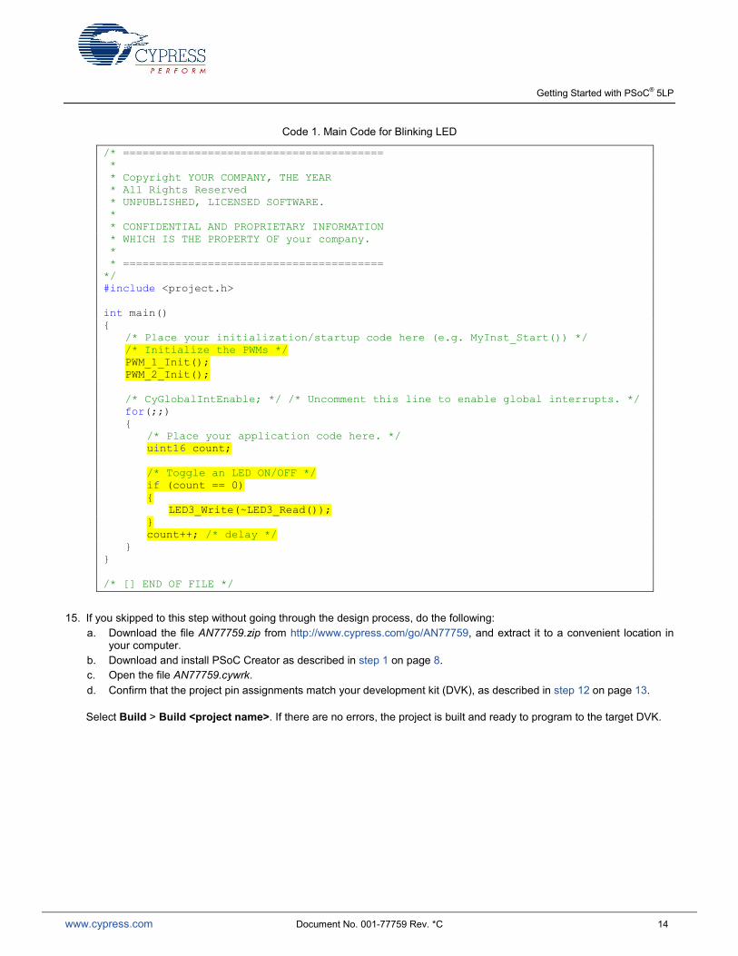
14. Open the file main.c, and add code to toggle LED4. You can refer to the Component datasheet for output pin-related API functions, or you can refer to the generated file LED4.h. The generated main.c has a framework for adding code; the code that you must add is highlighted, as Code 1 shows:
/* ======================================== * * Copyright YOUR COMPANY, THE YEAR * All Rights Reserved * UNPUBLISHED, LICENSED SOFTWARE. * * CONFIDENTIAL AND PROPRIETARY INFORMATION * WHICH IS THE PROPERTY OF your company. * * ======================================== */ #include <project.h> int main() /* Place your initialization/startup code here (e.g. MyInst_Start()) */ /* Initialize the PWMs */ PWM_1_Init(); PWM_2_Init(); /* CyGlobalIntEnable; */ /* Uncomment this line to enable global interrupts. */ for(;;) /* Place your application code here. */ uint16 count; /* Toggle an LED ON/OFF */ if (count == 0) LED3_Write(~LED3_Read()); count++; /* delay */ /* [] END OF FILE */
15. If you skipped to this step without going through the design process, do the following: a. Download the file AN77759.zip from http://www.cypress.com/go/AN77759, and extract it to a convenient location in
your computer. b. Download and install PSoC Creator as described in step 1 on page 8. c. Open the file AN77759.cywrk. d. Confirm that the project pin assignments match your development kit (DVK), as described in step 12 on page 13.
Select Build > Build <project name>. If there are no errors, the project is built and ready to program to the target DVK.
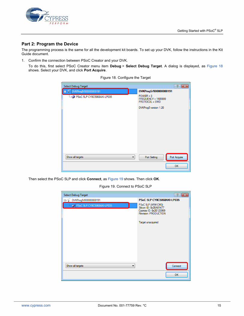
Part 2: Program the Device The programming process is the same for all the development kit boards. To set up your DVK, follow the instructions in the Kit Guide document.
1. Confirm the connection between PSoC Creator and your DVK. To do this, first select PSoC Creator menu item Debug > Select Debug Target. A dialog is displayed, as Figure 18 shows. Select your DVK, and click Port Acquire.
Figure 18. Configure the Target
Then select the PSoC 5LP and click Connect, as Figure 19 shows. Then click OK.
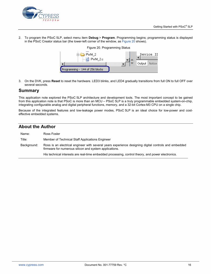
2. To program the PSoC 5LP, select menu item Debug > Program. Programming begins; programming status is displayed in the PSoC Creator status bar (the lower-left corner of the window, as Figure 20 shows).
Figure 20. Programming Status
3. On the DVK, press Reset to reset the hardware. LED3 blinks, and LED4 gradually transitions from full ON to full OFF over several seconds.
Summary This application note explored the PSoC 5LP architecture and development tools. The most important concept to be gained from this application note is that PSoC is more than an MCU – PSoC 5LP is a truly programmable embedded system-on-chip, integrating configurable analog and digital peripheral functions, memory, and a 32-bit Cortex-M3 CPU on a single chip.
Because of the integrated features and low-leakage power modes, PSoC 5LP is an ideal choice for low-power and cost- effective embedded systems.
About the Author Name: Ross Fosler
Title: Member of Technical Staff Applications Engineer
Background: Ross is an electrical engineer with several years experience designing digital controls and embedded firmware for numerous silicon and system applications.
His technical interests are real-time embedded processing, control theory, and power electronics.
Worldwide Sales and Design Support Cypress maintains a worldwide network of offices, solution centers, manufacturer’s representatives, and distributors. To find the office closest to you, visit us at Cypress Locations.
Products Automotive cypress.com/go/automotive
Clocks & Buffers cypress.com/go/clocks
Interface cypress.com/go/interface
Lighting & Power Control cypress.com/go/powerpsoc cypress.com/go/plc
Memory cypress.com/go/memory
PSoC cypress.com/go/psoc
Touch Sensing cypress.com/go/touch
USB Controllers cypress.com/go/usb
Wireless/RF cypress.com/go/wireless
PSoC® Solutions psoc.cypress.com/solutions
PSoC 1 | PSoC 3 |PSoC 5LP
Cypress Developer Community Community | Forums | Blogs | Video | Training
Technical Support
cypress.com/go/support
QDR is a registered trademark of Cypress Semiconductor Corp. All other trademarks or registered trademarks referenced herein are the property of their respective owners.
Cypress Semiconductor 198 Champion Court San Jose, CA 95134-1709