68
Getting to the Bottom of CHIRP Technology Jen Matsis Vice President - Sales & Marketing AIRMAR Technology
Getting to the Bottom of CHIRP Technology Jen Matsis Vice President - Sales & Marketing AIRMAR Technology
Seminar Agenda
• Understanding CHIRP technology • Learning the difference between CHIRP vs. NON-CHIRP
transducers • AIRMAR’s CHIRP-ready transducer product line • Getting the answers to your CHIRP questions
What is CHIRP?
• CHIRP has been used by the military, geologists and oceanographers since the 1950’s
• This is the first time the technology has been
available to the recreational, sport fishing and light commercial industry… and at an affordable price
CHIRP Starts with the Transducer
• AIRMAR transducers are the enabling technology for manufacturers designing CHIRP sounders.
• Only echosounders using AIRMAR CHIRP
transducers can operate as a CHIRP system. – Furuno’s DFF1-UHD – Garmin’s GSD 26 – Simrad’s BSM-2 – Raymarine’s ClearPulse 450C
How Does CHIRP Work?
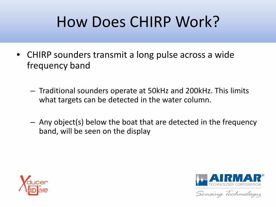
• CHIRP sounders transmit a long pulse across a wide frequency band
– Traditional sounders operate at 50kHz and 200kHz. This limits
what targets can be detected in the water column.
– Any object(s) below the boat that are detected in the frequency band, will be seen on the display
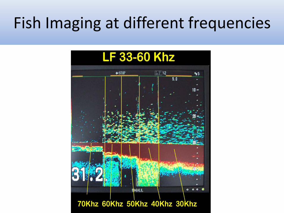
Fish Imaging at different frequencies
CHIRP Starts with the Transducer
• AIRMAR’s new CHIRP transducers are engineered with ceramics designed to operate over a broad range of frequencies (28kHz – 210kHz) with no sensitivity loss.
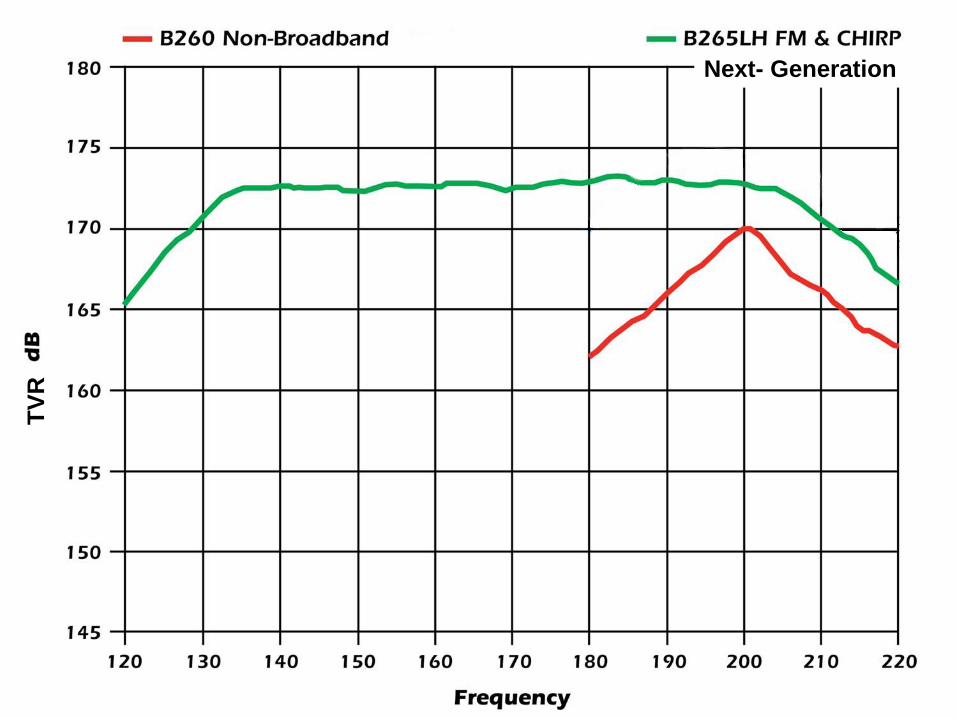
TVR
Next- Generation
CHIRP vs NON-CHIRP: What’s the difference?
CHIRP vs NON-CHIRP Fishfinders
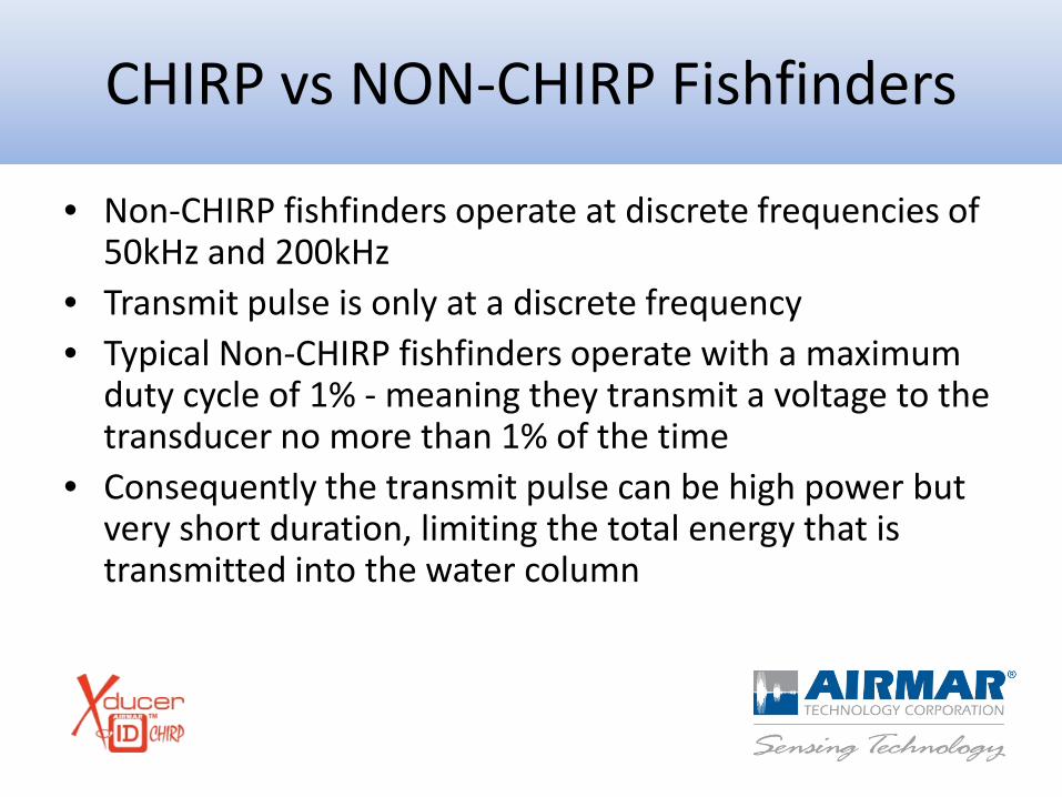
• Non-CHIRP fishfinders operate at discrete frequencies of 50kHz and 200kHz
• Transmit pulse is only at a discrete frequency • Typical Non-CHIRP fishfinders operate with a maximum
duty cycle of 1% - meaning they transmit a voltage to the transducer no more than 1% of the time
• Consequently the transmit pulse can be high power but very short duration, limiting the total energy that is transmitted into the water column
CHIRP vs NON-CHIRP Fishfinders
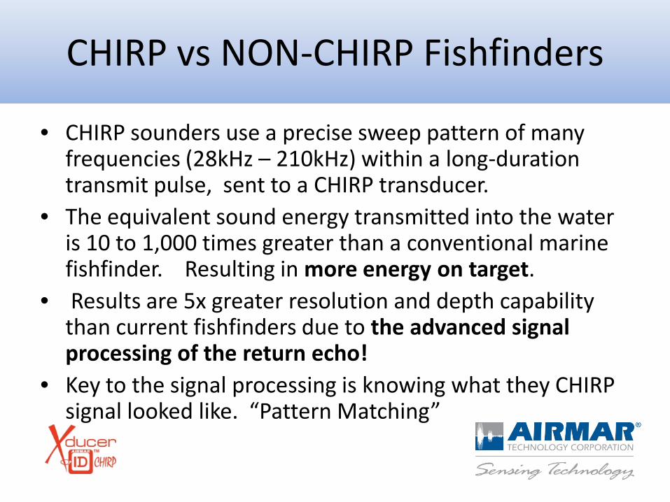
• CHIRP sounders use a precise sweep pattern of many frequencies (28kHz – 210kHz) within a long-duration transmit pulse, sent to a CHIRP transducer.
• The equivalent sound energy transmitted into the water is 10 to 1,000 times greater than a conventional marine fishfinder. Resulting in more energy on target.
• Results are 5x greater resolution and depth capability than current fishfinders due to the advanced signal processing of the return echo!
• Key to the signal processing is knowing what they CHIRP signal looked like. “Pattern Matching”
CHIRP vs NON-CHIRP Fishfinders
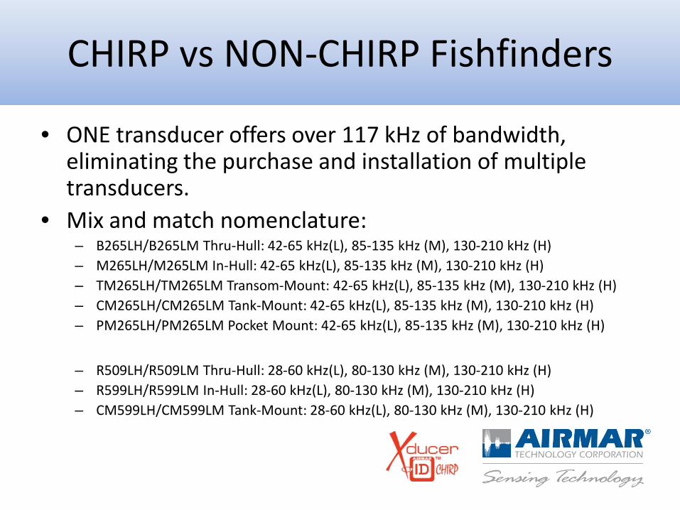
• ONE transducer offers over 117 kHz of bandwidth, eliminating the purchase and installation of multiple transducers.
• Mix and match nomenclature: – B265LH/B265LM Thru-Hull: 42-65 kHz(L), 85-135 kHz (M), 130-210 kHz (H) – M265LH/M265LM In-Hull: 42-65 kHz(L), 85-135 kHz (M), 130-210 kHz (H) – TM265LH/TM265LM Transom-Mount: 42-65 kHz(L), 85-135 kHz (M), 130-210 kHz (H) – CM265LH/CM265LM Tank-Mount: 42-65 kHz(L), 85-135 kHz (M), 130-210 kHz (H) – PM265LH/PM265LM Pocket Mount: 42-65 kHz(L), 85-135 kHz (M), 130-210 kHz (H)
– R509LH/R509LM Thru-Hull: 28-60 kHz(L), 80-130 kHz (M), 130-210 kHz (H) – R599LH/R599LM In-Hull: 28-60 kHz(L), 80-130 kHz (M), 130-210 kHz (H) – CM599LH/CM599LM Tank-Mount: 28-60 kHz(L), 80-130 kHz (M), 130-210 kHz (H)
Understanding “Q”
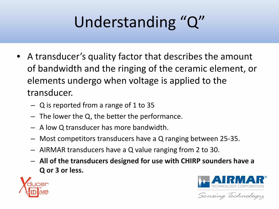
• A transducer’s quality factor that describes the amount of bandwidth and the ringing of the ceramic element, or elements undergo when voltage is applied to the transducer. – Q is reported from a range of 1 to 35 – The lower the Q, the better the performance. – A low Q transducer has more bandwidth. – Most competitors transducers have a Q ranging between 25-35. – AIRMAR transducers have a Q value ranging from 2 to 30. – All of the transducers designed for use with CHIRP sounders have a
Q or 3 or less.
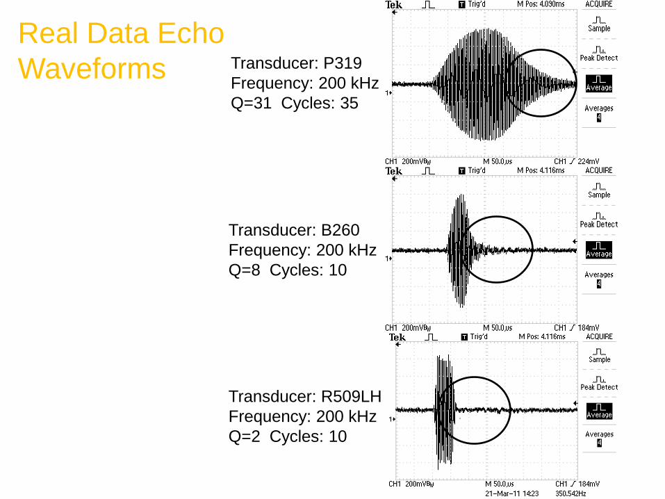
Real Data Echo Waveforms Transducer: P319
Frequency: 200 kHz Q=31 Cycles: 35
Transducer: B260 Frequency: 200 kHz Q=8 Cycles: 10
Transducer: R509LH Frequency: 200 kHz Q=2 Cycles: 10
Understanding “Q”
• A high Q means the transmitted acoustic pulse is extensively elongated
• A low Q means the acoustic pulse has minimal elongation, and closely resembles the drive waveform
• Q values range from 2 to 35 • With a high Q transducer, two close targets will blend
together, and will not be displayed as individual targets
Understanding “Q” (Con’t.)
• With a low Q transducer, two close targets can be distinguished, and each target will be resolved on the display
• Transducers that are termed “Broadband” have Q’s of 2 or 3, and can also be used for CHIRP
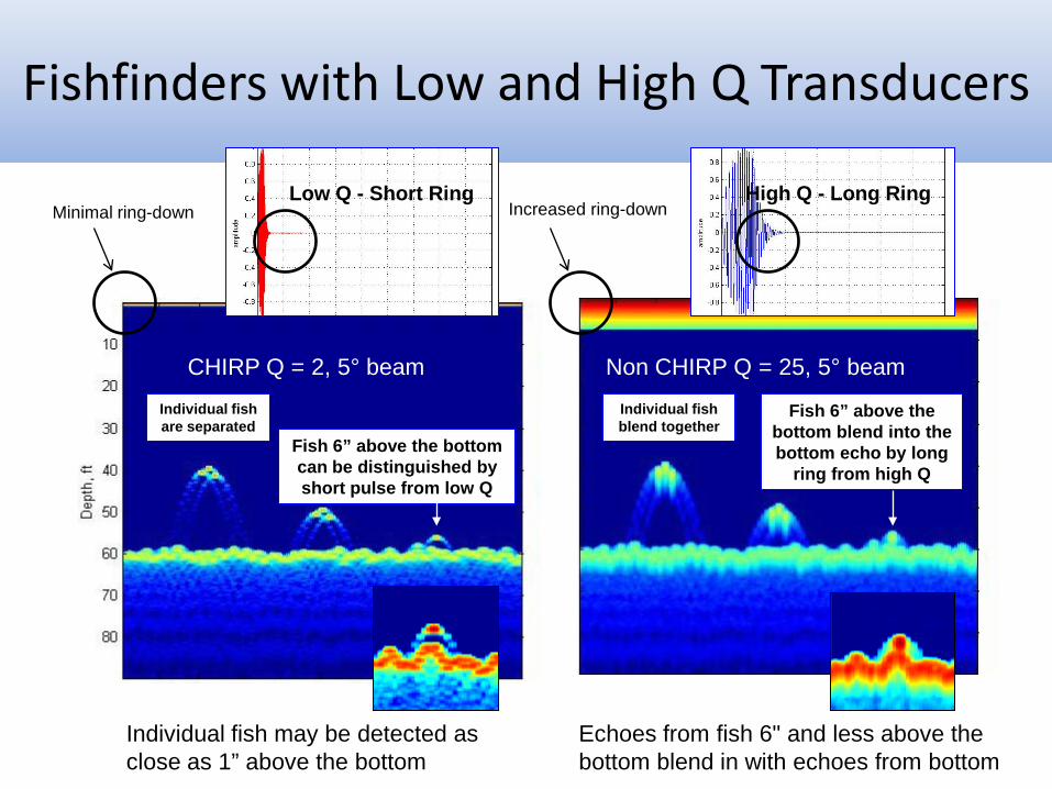
Fishfinders with Low and High Q Transducers
Fish 6” above the bottom blend into the bottom echo by long
ring from high Q
Echoes from fish 6" and less above the bottom blend in with echoes from bottom
Individual fish may be detected as close as 1” above the bottom
Fish 6” above the bottom can be distinguished by short pulse from low Q
Individual fish blend together
Individual fish are separated
High Q - Long Ring
CHIRP Q = 2, 5° beam Non CHIRP Q = 25, 5° beam
Low Q - Short Ring Minimal ring-down Increased ring-down
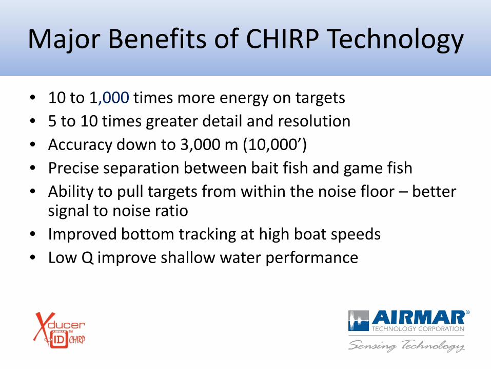
Major Benefits of CHIRP Technology
• 10 to 1,000 times more energy on targets • 5 to 10 times greater detail and resolution • Accuracy down to 3,000 m (10,000’) • Precise separation between bait fish and game fish • Ability to pull targets from within the noise floor – better
signal to noise ratio • Improved bottom tracking at high boat speeds • Low Q improve shallow water performance
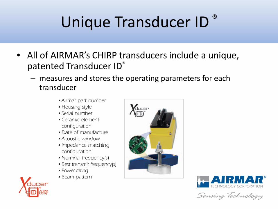
Unique Transducer ID ®
• All of AIRMAR’s CHIRP transducers include a unique, patented Transducer ID® – measures and stores the operating parameters for each
transducer
Unique Transducer ID ®
• All of AIRMAR’s CHIRP transducers include a unique, patented Transducer ID® – measures and stores the operating parameters for each
transducer – enables the fishfinder to automatically configure itself to the
transducer being used – minimal set up or customization is needed – transmitting across
the bandwidth is done automatically by the sounder • Stored data also assists with troubleshooting, warranty
or required information about the transducer
Example Screenshots: Courtesy of Furuno, Garmin,
Raymarine & Simrad
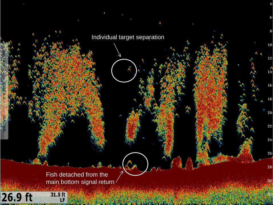
Individual target separation
Fish detached from the main bottom signal return
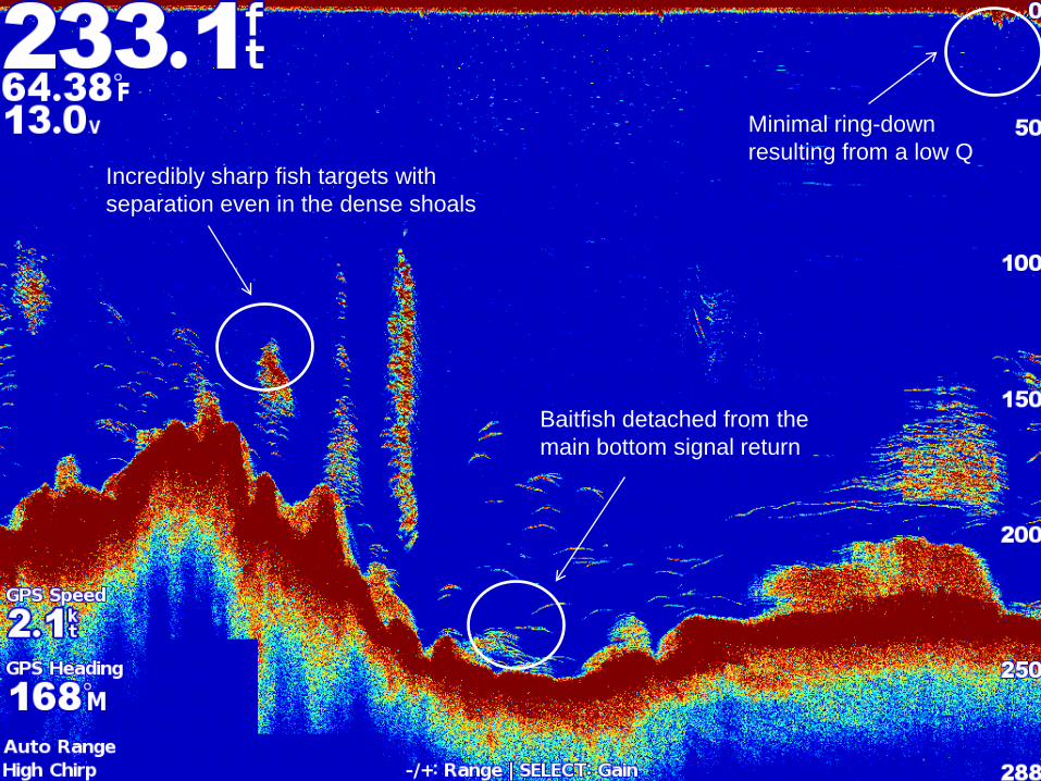
Incredibly sharp fish targets with separation even in the dense shoals
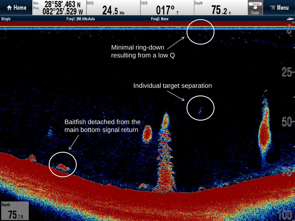
Baitfish detached from the main bottom signal return
Minimal ring-down resulting from a low Q
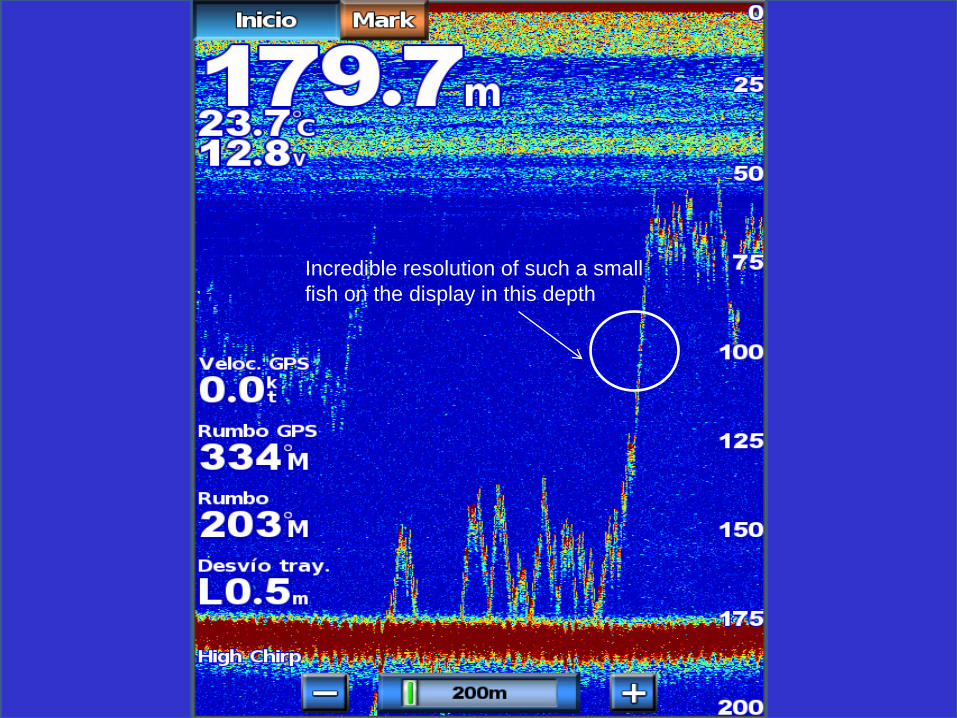
Incredible resolution of such a small fish on the display in this depth
Baitfish detached from the main bottom signal return
Individual target separation
Minimal ring-down resulting from a low Q
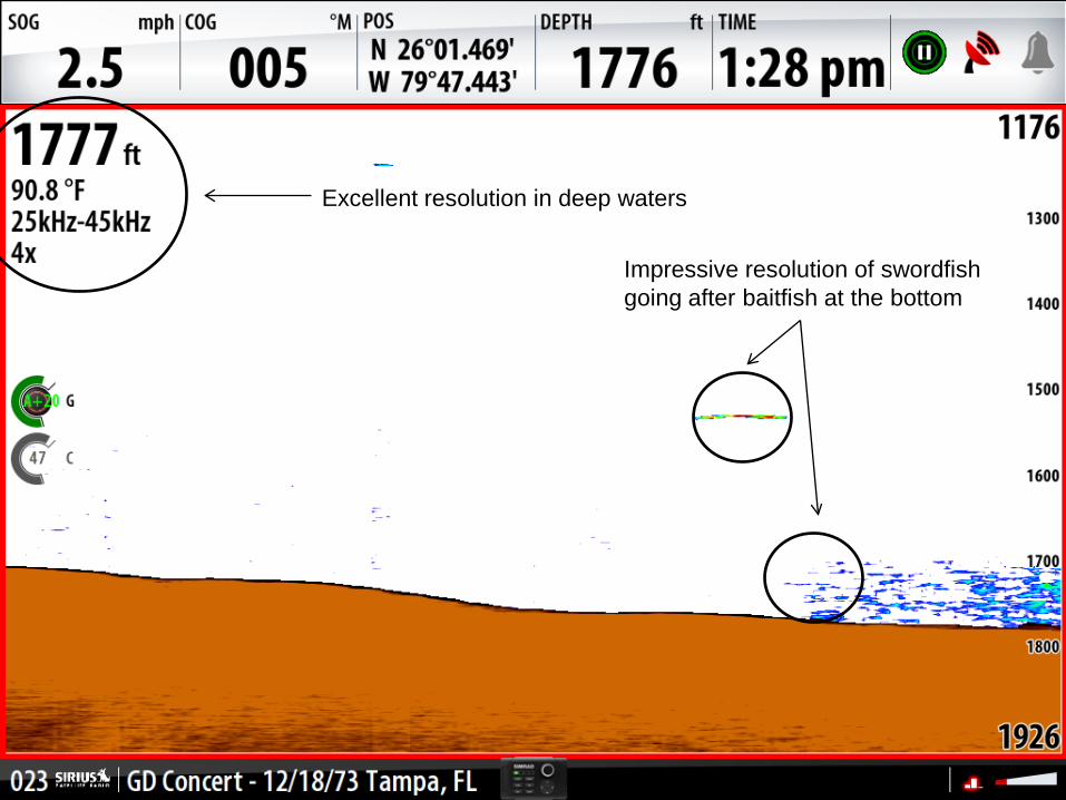
Impressive resolution of swordfish going after baitfish at the bottom
Excellent resolution in deep waters
The CHIRP Product Line
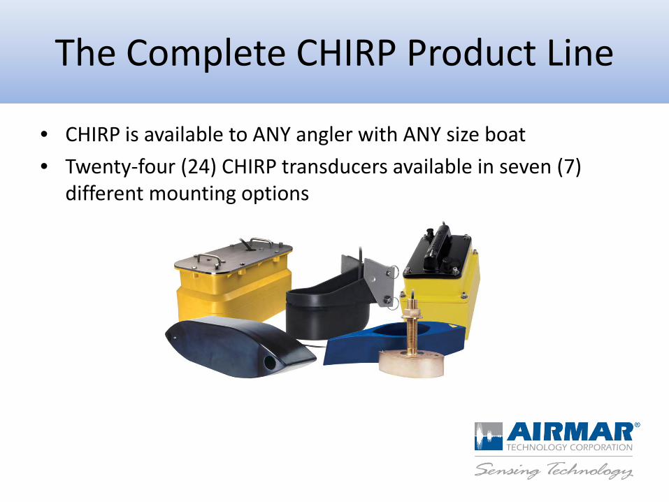
• CHIRP is available to ANY angler with ANY size boat • Twenty-four (24) CHIRP transducers available in seven (7)
different mounting options
The Complete CHIRP Product Line
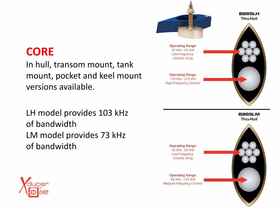
CORE In hull, transom mount, tank mount, pocket and keel mount versions available. LH model provides 103 kHz of bandwidth LM model provides 73 kHz of bandwidth
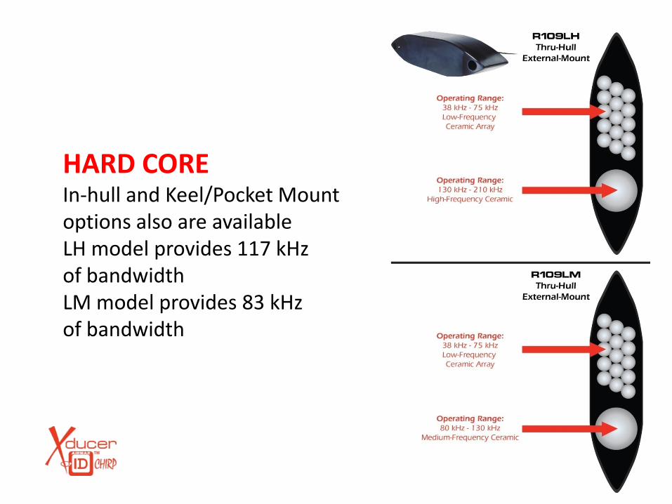
HARD CORE In-hull and Keel/Pocket Mount options also are available LH model provides 117 kHz of bandwidth LM model provides 83 kHz of bandwidth
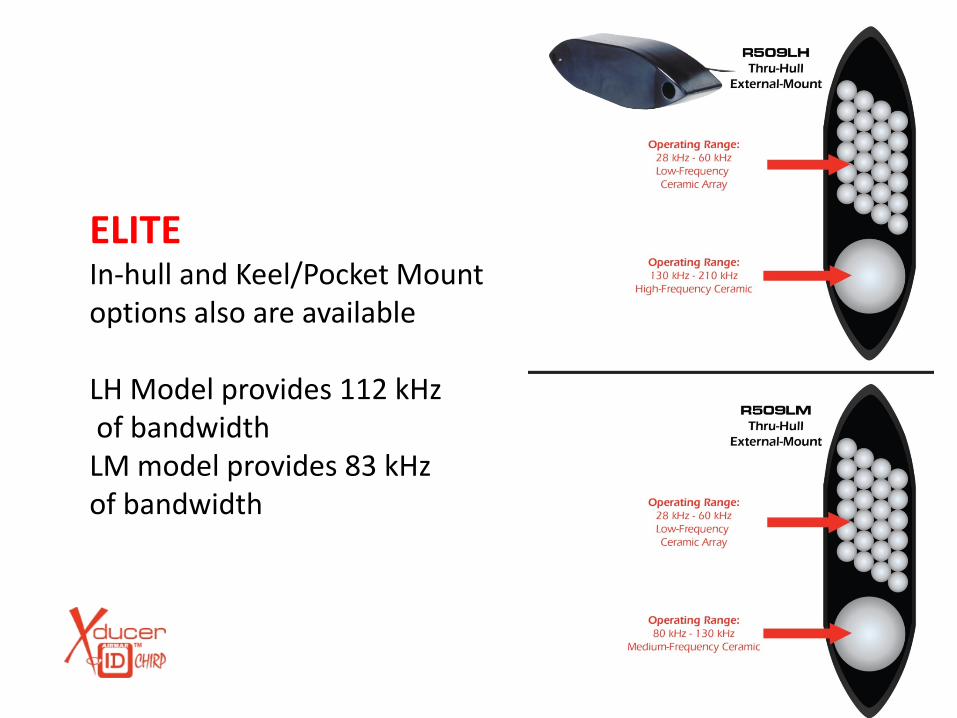
ELITE In-hull and Keel/Pocket Mount options also are available LH Model provides 112 kHz of bandwidth LM model provides 83 kHz of bandwidth
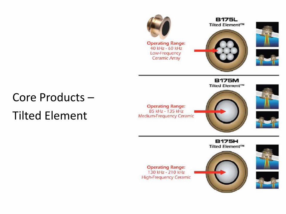
Core Products – Tilted Element
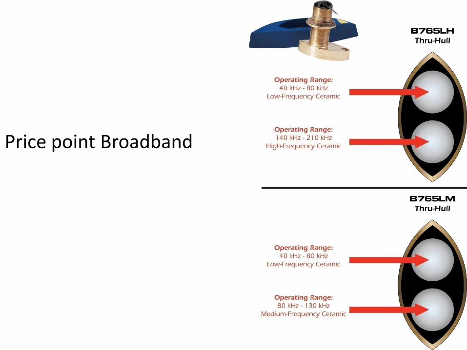
Price point Broadband
• 80 kHz – 130 kHz or 85 kHz – 135 kHz • Better target resolution than low frequency band • Ability to sound deeper than the high frequency band • Covers popular fishing frequencies of 88 kHz & 107 kHz
Advantages of the Middle Frequency
Variations in Beamwidth
• Low – 28 kHz to 60 kHz provides 23° to 9° beamwidth • Low – 38 kHz to 75 kHz provides 19° to 10° beamwidth • Low – 40 kHz to 60 kHz provides 32° to 21° beamwidth • Low – 40 kHz to 75 kHz provides 32° to 21° beamwidth • Low – 42 kHz to 65 kHz provides 25° to 16° beamwidth
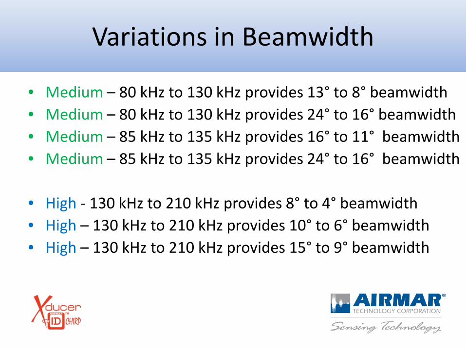
Variations in Beamwidth
• Medium – 80 kHz to 130 kHz provides 13° to 8° beamwidth • Medium – 80 kHz to 130 kHz provides 24° to 16° beamwidth • Medium – 85 kHz to 135 kHz provides 16° to 11° beamwidth • Medium – 85 kHz to 135 kHz provides 24° to 16° beamwidth • High - 130 kHz to 210 kHz provides 8° to 4° beamwidth • High – 130 kHz to 210 kHz provides 10° to 6° beamwidth • High – 130 kHz to 210 kHz provides 15° to 9° beamwidth
• CHIRP transmits across a wide frequency band • The combination of a CHIRP sounder, a broadband transducer and the
fishfinder’s DSP can transmit over 10x’s more energy in the water – Able to detect bottom >3000 meters and fish or objects in the water column in more difficult
conditions that ever before
• Dramatically better signal to noise ratios resulting in better performance in noisy environments and tracking at high speeds
• One transducer covers all the popular fishing frequencies • Transducer ID feature optimizes the system
Summary

• Entire system is much more sophisticated • New Transducer ID features • Addition of heat sinks for thermal dissipation • Common impedance requires transformers
and inductors
Why Do They Cost More?
• A single transmission line sounder has one transceiver for both the high and low frequency signal – ie: BSM1, DSM300, GSD24, FCV585
• A dual transmission line sounder has two transceivers – ie: DSM400, FCV1100, FCV295
Single vs Dual Transmission Line
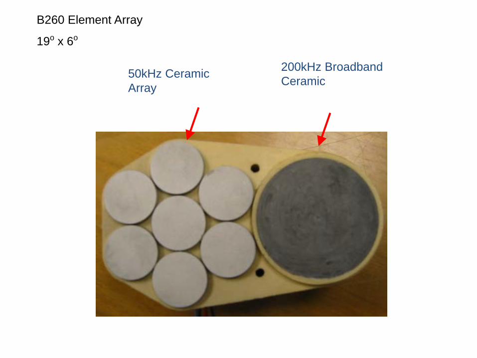
B260 Element Array
19o x 6o
200kHz Broadband Ceramic 50kHz Ceramic
Array
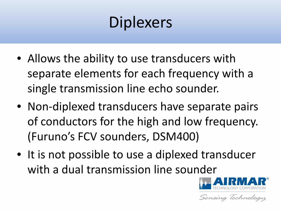
• Allows the ability to use transducers with separate elements for each frequency with a single transmission line echo sounder.
• Non-diplexed transducers have separate pairs of conductors for the high and low frequency. (Furuno’s FCV sounders, DSM400)
• It is not possible to use a diplexed transducer with a dual transmission line sounder
Diplexers
Dual vs. Single Transmission Line Transducers
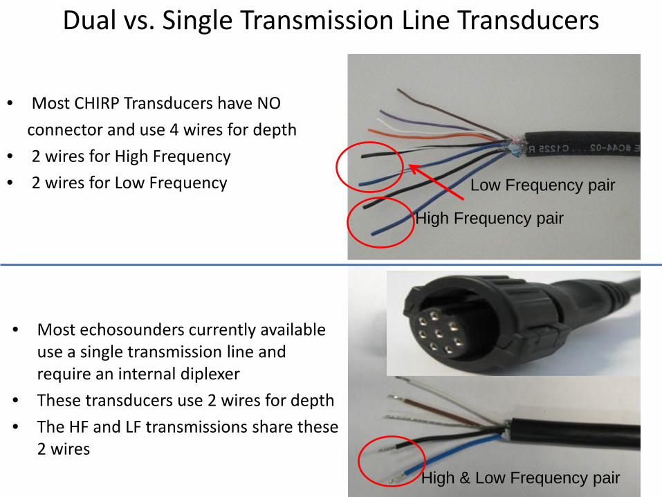
• Most CHIRP Transducers have NO connector and use 4 wires for depth • 2 wires for High Frequency • 2 wires for Low Frequency
• Most echosounders currently available use a single transmission line and require an internal diplexer
• These transducers use 2 wires for depth • The HF and LF transmissions share these
2 wires
High Frequency pair
Low Frequency pair
High & Low Frequency pair
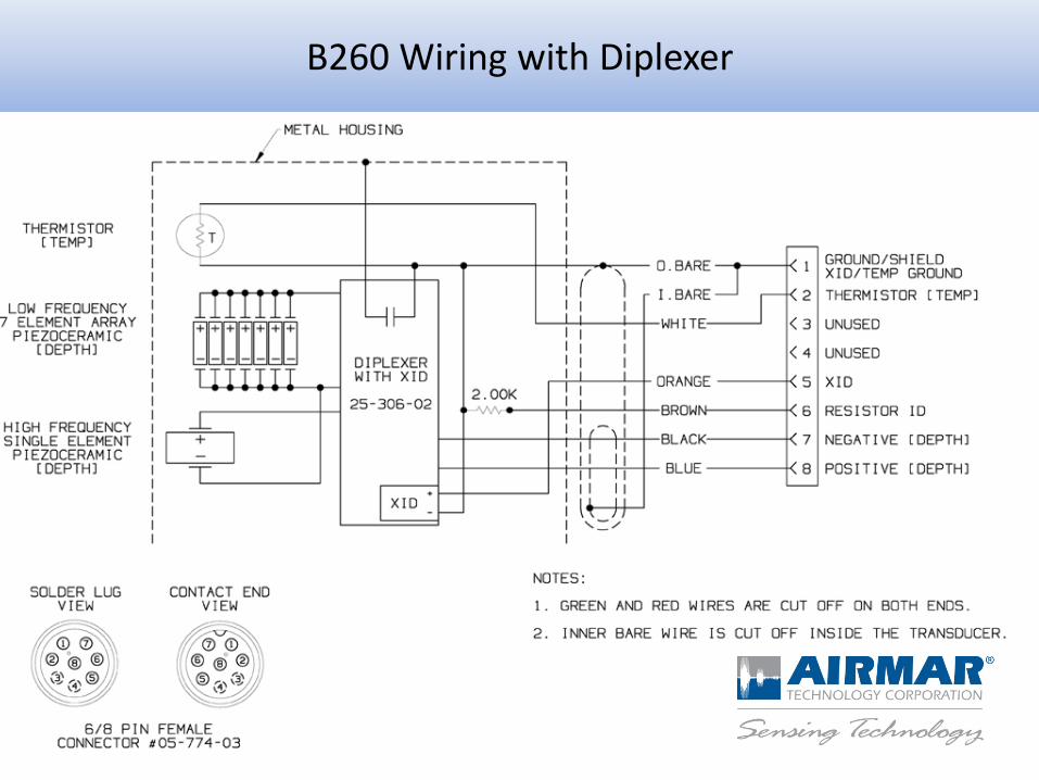
B260 Wiring with Diplexer
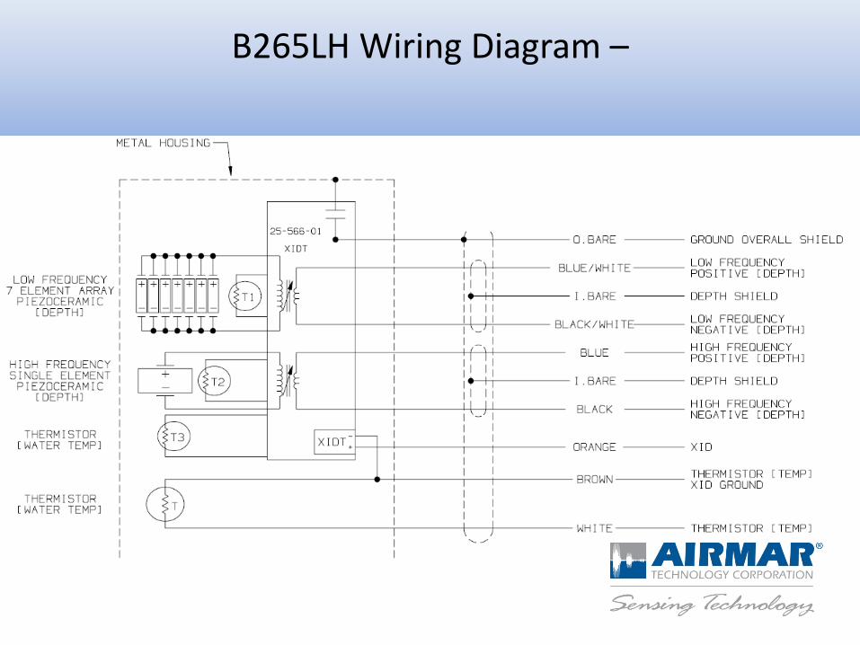
B265LH Wiring Diagram –
Transducer Installation & Placement
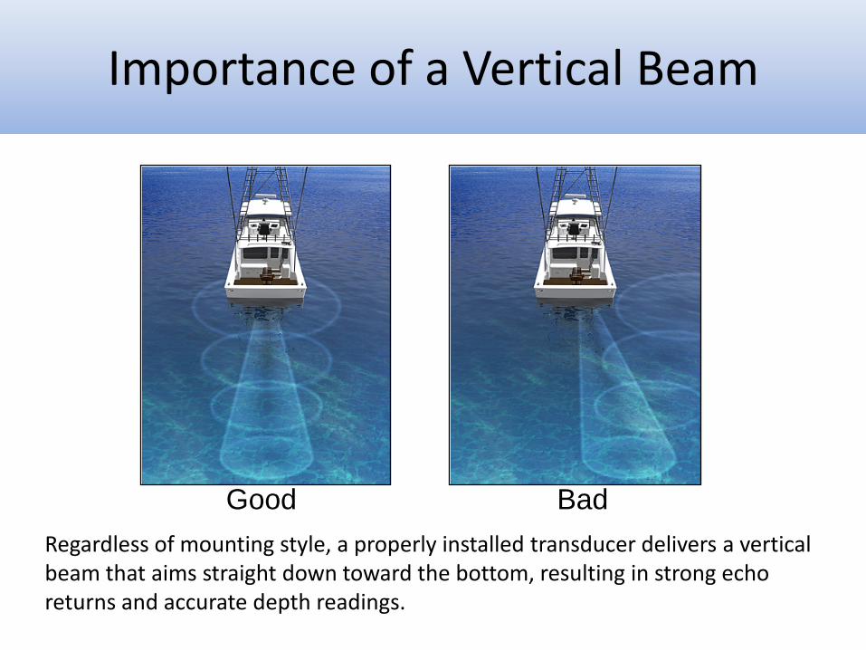
Regardless of mounting style, a properly installed transducer delivers a vertical beam that aims straight down toward the bottom, resulting in strong echo returns and accurate depth readings.
Good Bad
Importance of a Vertical Beam
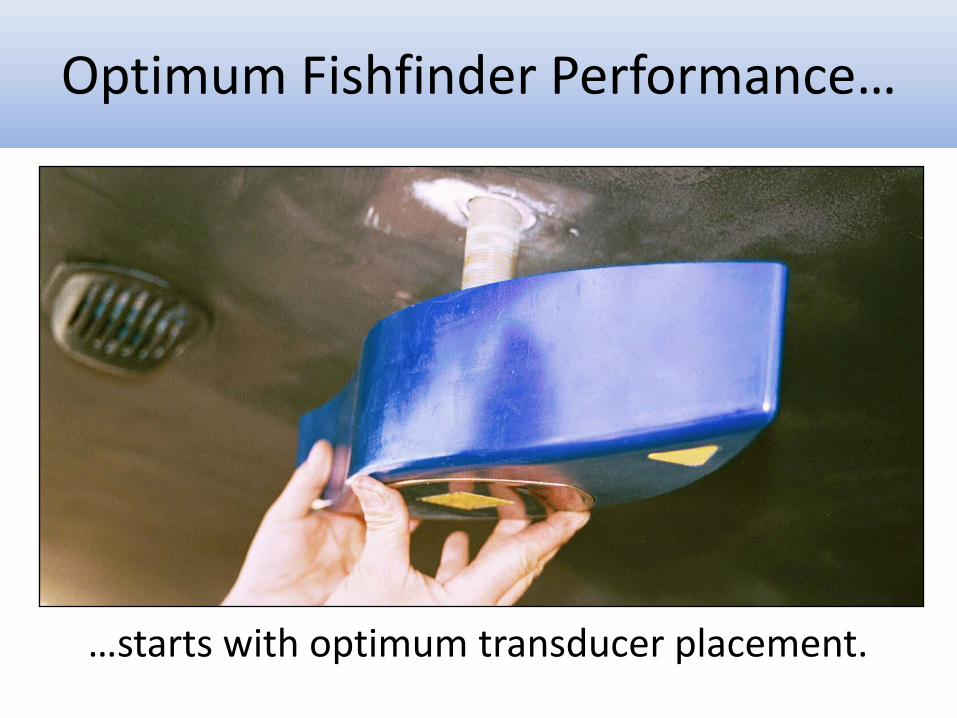
…starts with optimum transducer placement.
Optimum Fishfinder Performance…
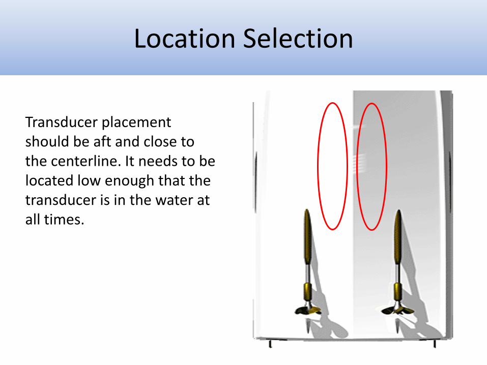
Transducer placement should be aft and close to the centerline. It needs to be located low enough that the transducer is in the water at all times.
Location Selection
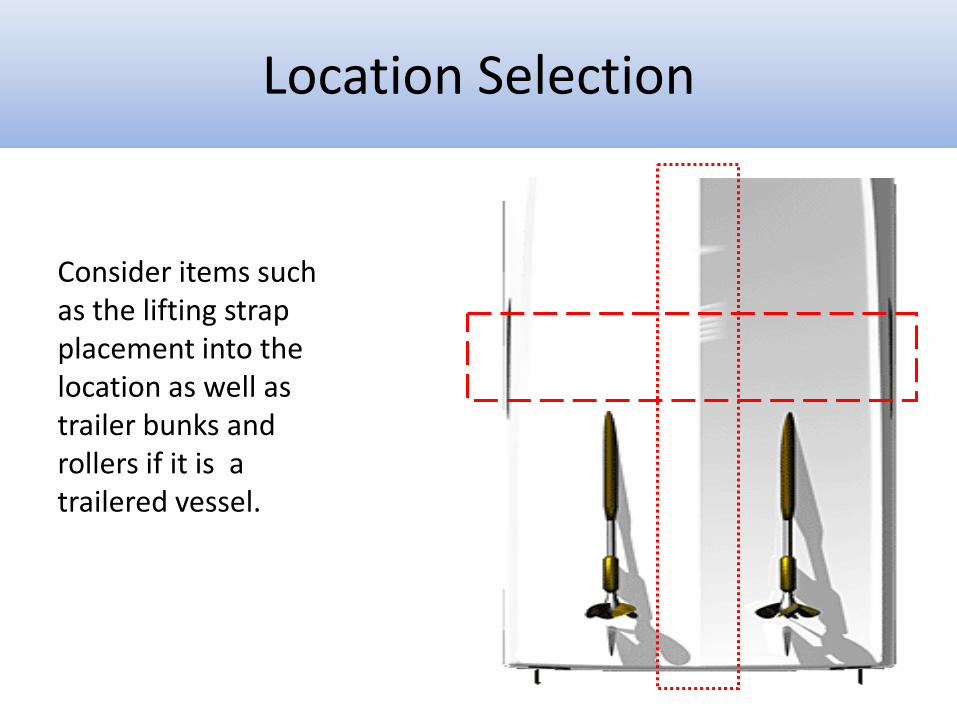
Consider items such as the lifting strap placement into the location as well as trailer bunks and rollers if it is a trailered vessel.
Location Selection
BOW
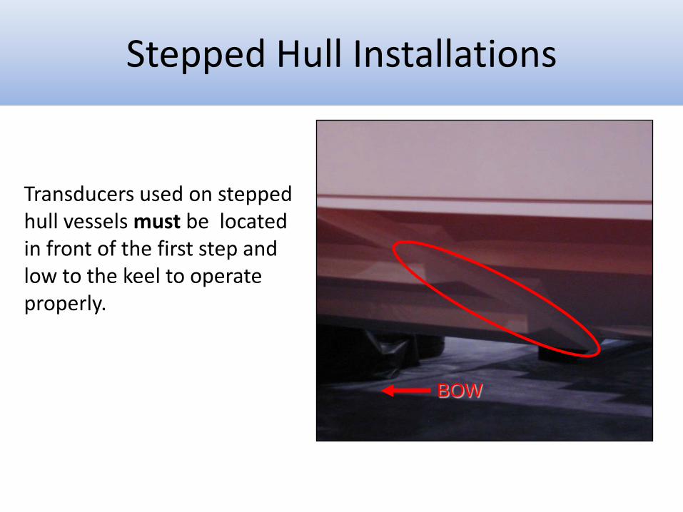
Transducers used on stepped hull vessels must be located in front of the first step and low to the keel to operate properly.
Stepped Hull Installations
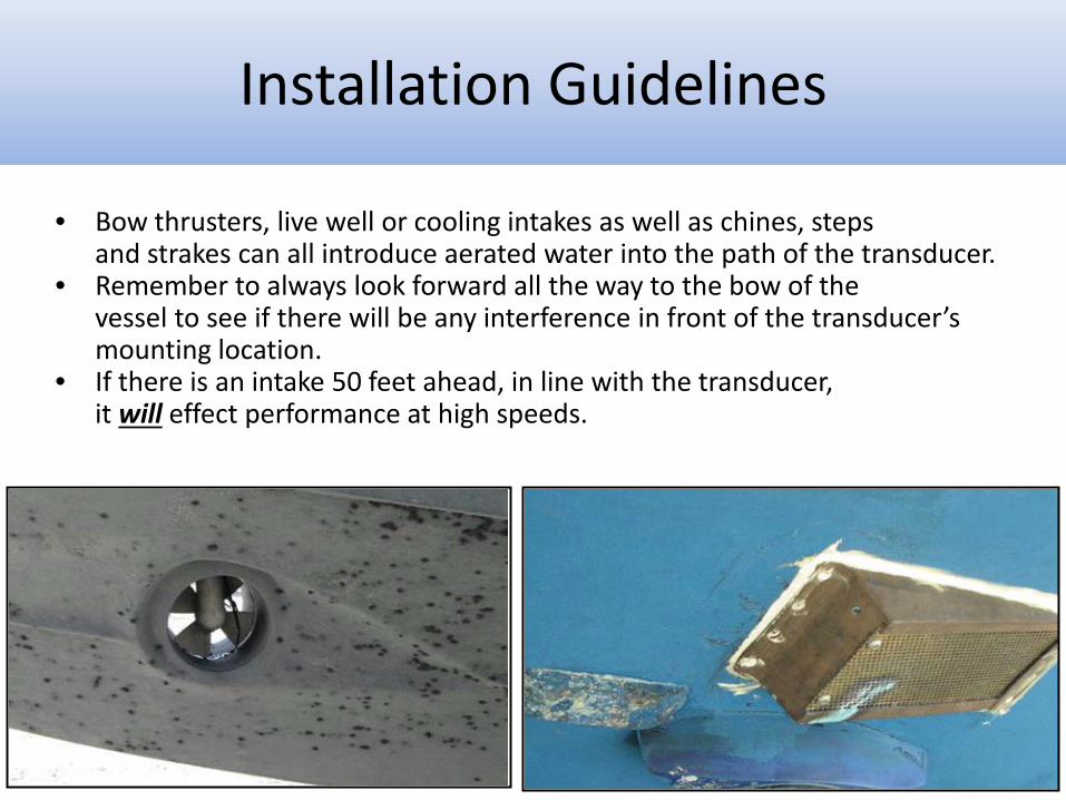
• Bow thrusters, live well or cooling intakes as well as chines, steps and strakes can all introduce aerated water into the path of the transducer. • Remember to always look forward all the way to the bow of the vessel to see if there will be any interference in front of the transducer’s
mounting location. • If there is an intake 50 feet ahead, in line with the transducer, it will effect performance at high speeds.
Installation Guidelines
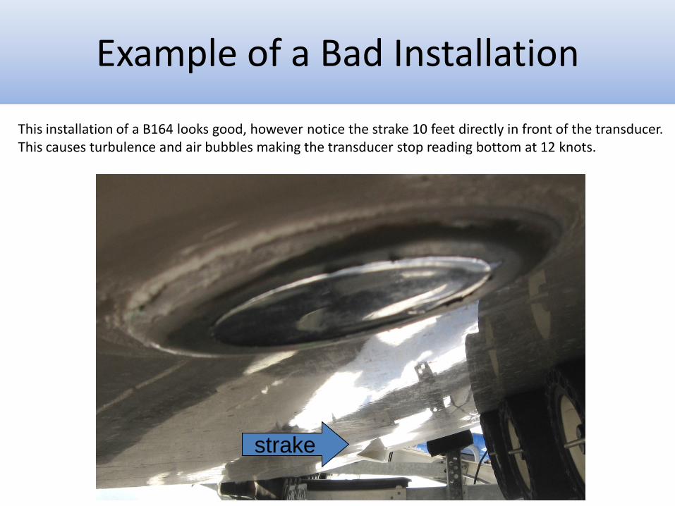
This installation of a B164 looks good, however notice the strake 10 feet directly in front of the transducer. This causes turbulence and air bubbles making the transducer stop reading bottom at 12 knots.
strake
Bad Installation Example of a Bad Installation
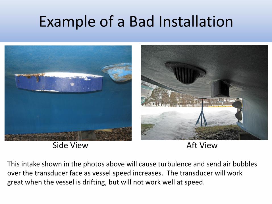
Side View Aft View
This intake shown in the photos above will cause turbulence and send air bubbles over the transducer face as vessel speed increases. The transducer will work great when the vessel is drifting, but will not work well at speed.
Example of a Bad Installation
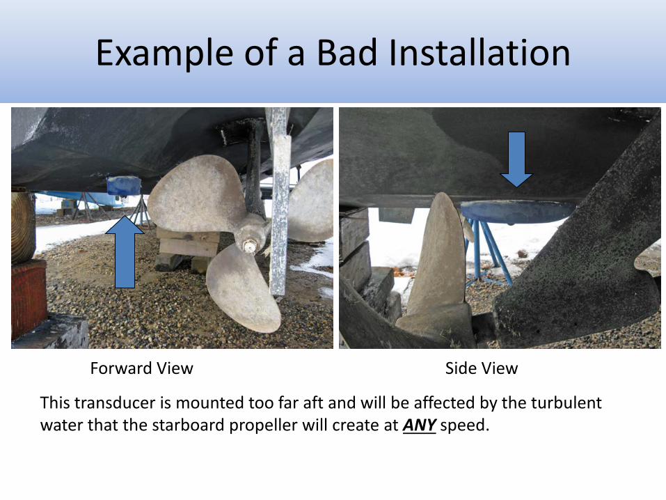
Forward View Side View
This transducer is mounted too far aft and will be affected by the turbulent water that the starboard propeller will create at ANY speed.
Example of a Bad Installation
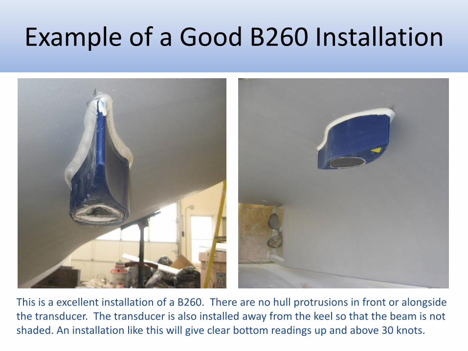
This is a excellent installation of a B260. There are no hull protrusions in front or alongside the transducer. The transducer is also installed away from the keel so that the beam is not shaded. An installation like this will give clear bottom readings up and above 30 knots.
Example of a Good B260 Installation
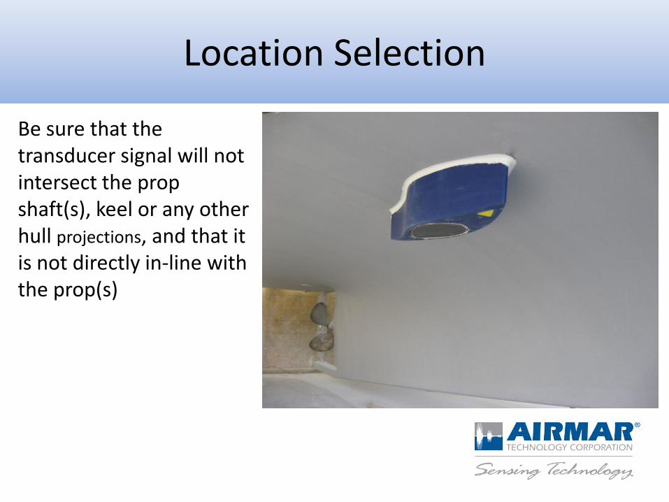
Be sure that the transducer signal will not intersect the prop shaft(s), keel or any other hull projections, and that it is not directly in-line with the prop(s)
Location Selection
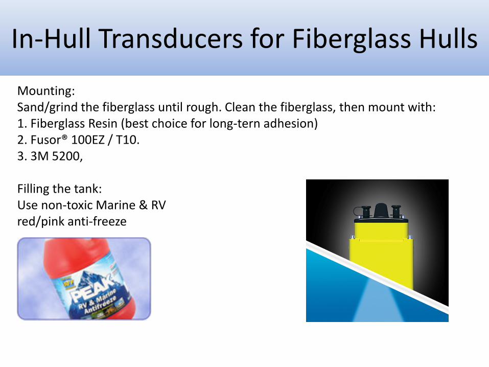
Mounting: Sand/grind the fiberglass until rough. Clean the fiberglass, then mount with: 1. Fiberglass Resin (best choice for long-tern adhesion) 2. Fusor® 100EZ / T10. 3. 3M 5200, Filling the tank: Use non-toxic Marine & RV red/pink anti-freeze
In-Hull Transducers for Fiberglass Hulls
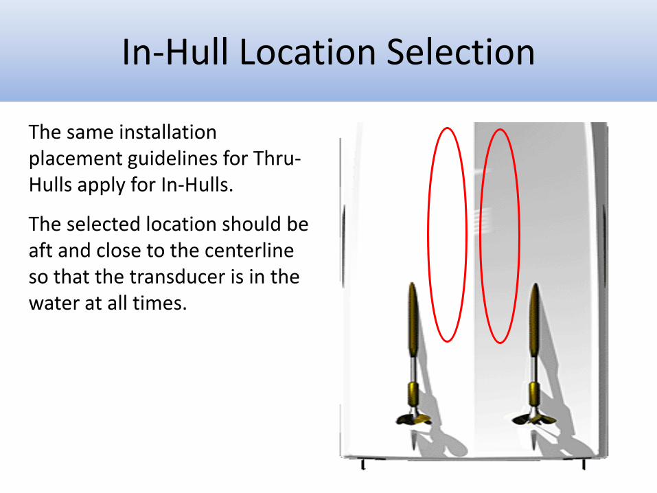
The same installation placement guidelines for Thru-Hulls apply for In-Hulls.
The selected location should be aft and close to the centerline so that the transducer is in the water at all times.
In-Hull Location Selection
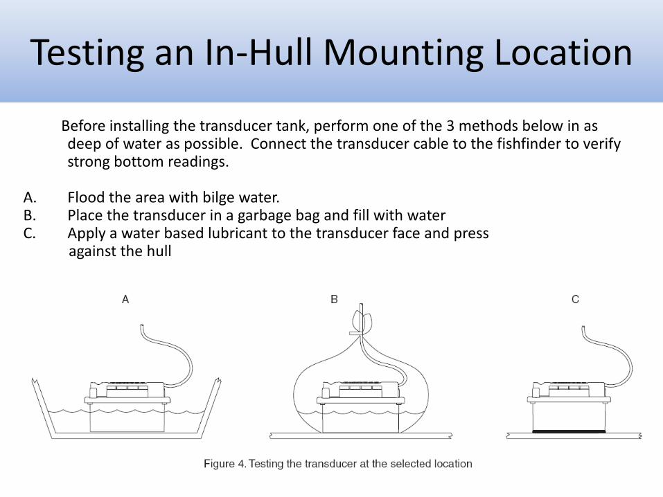
Before installing the transducer tank, perform one of the 3 methods below in as deep of water as possible. Connect the transducer cable to the fishfinder to verify strong bottom readings.
A. Flood the area with bilge water. B. Place the transducer in a garbage bag and fill with water C. Apply a water based lubricant to the transducer face and press against the hull
Testing an In-Hull Mounting Location
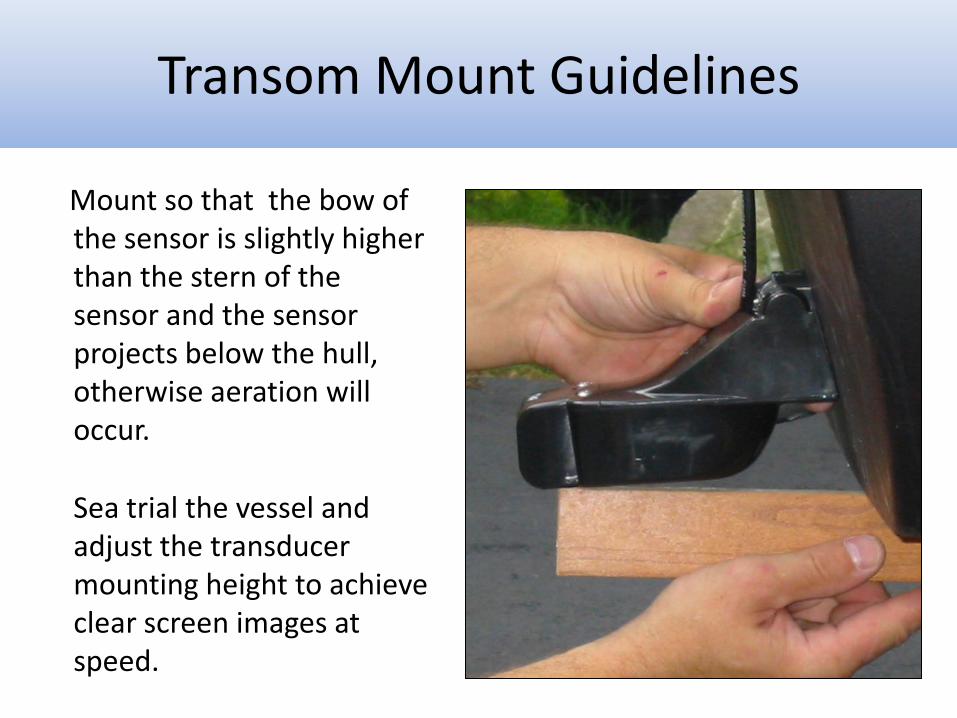
Mount so that the bow of the sensor is slightly higher than the stern of the sensor and the sensor projects below the hull, otherwise aeration will occur.
Sea trial the vessel and adjust the transducer mounting height to achieve clear screen images at speed.
Transom Mount Guidelines
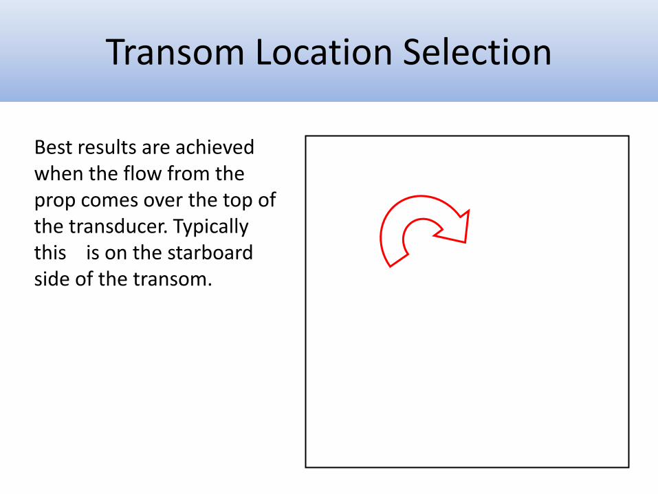
Best results are achieved when the flow from the prop comes over the top of the transducer. Typically this is on the starboard side of the transom.
Transom Location Selection
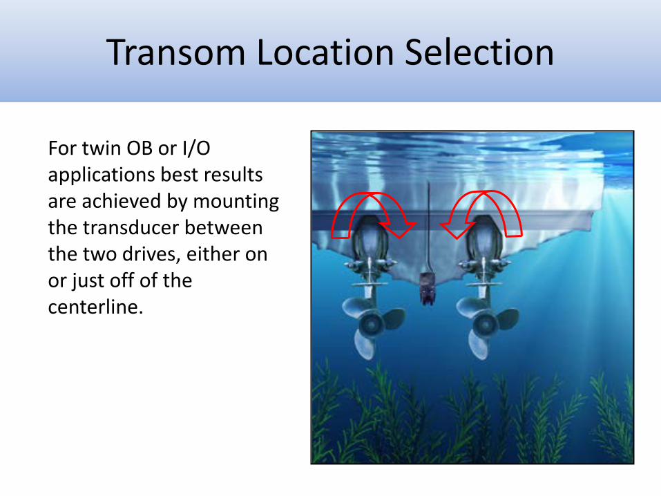
For twin OB or I/O applications best results are achieved by mounting the transducer between the two drives, either on or just off of the centerline.
Transom Location Selection
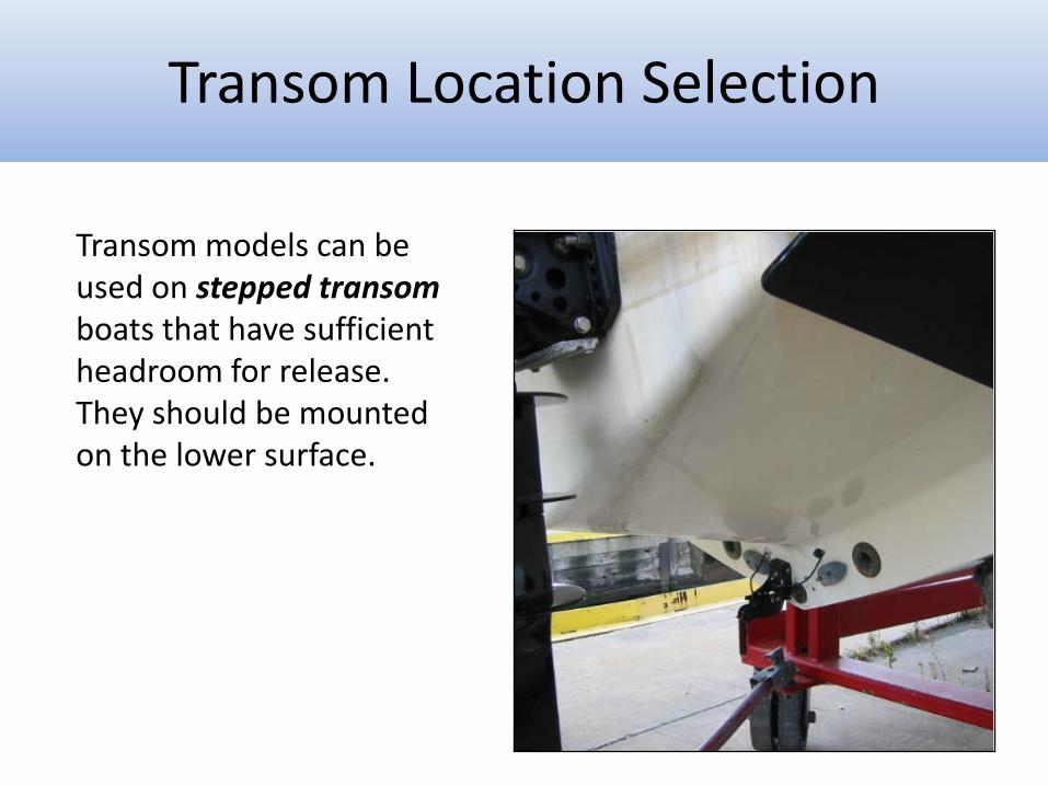
Transom models can be used on stepped transom boats that have sufficient headroom for release. They should be mounted on the lower surface.
Transom Location Selection
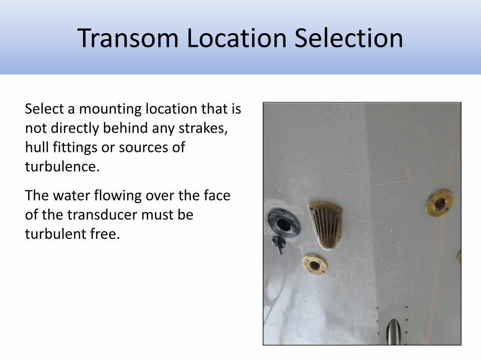
Select a mounting location that is not directly behind any strakes, hull fittings or sources of turbulence.
The water flowing over the face of the transducer must be turbulent free.
Transom Location Selection
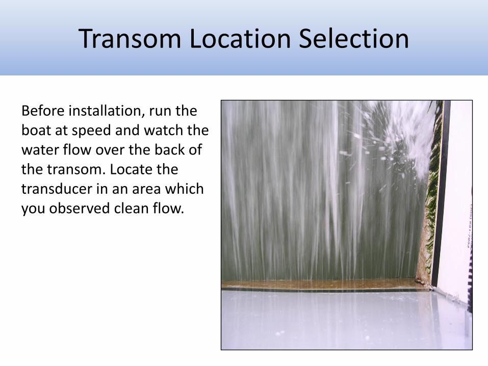
Before installation, run the boat at speed and watch the water flow over the back of the transom. Locate the transducer in an area which you observed clean flow.
Transom Location Selection
• If experiencing interference with a transom mounted transducer you must test drive the vessel to determine what speed the image is lost at.
• Move the transducer to it’s lowest position and retest. • If screen image is improved repeat until you are satisfied with
results. • If screen image gets worse, move transducer up and re-test until
improvement is seen.
Transom Mount Flow Noise
• Perform a slow but constant turn to the side of the hull that the transom transducer is mounted. Gradually increase rate of turn. If screen image improves the transducer needs to be mounted lower in the water.
• If screen image is worse when turning to the same side as the
transducer try turning the opposite direction. This would indicate the transducer needs to be mounted higher in the water.
Transom Mount Flow Noise


