340
L Manual Global Drive Drive PLC Developer Studio Global Drive PLC Developer Studio

L
Manual
Global DriveDrive PLC Developer Studio
Global DrivePLC Developer Studio

This Manual is valid for the Drive PLC Developer Studio V02.00.
Important note:
The software is supplied to the user as described in this document. Any risks resulting from its quality or use remain the responsibility of theuser. The user must provide all safety measures protecting against possible maloperation.
We do not take any liability for direct or indirect damage, e.g. profit loss, order loss or any loss regarding business.
� 2005 Lenze Drive Systems GmbH
No part of this documentation may be copied or made available to third parties without the explicit written approval of Lenze Drive SystemsGmbH.
All information given in this online documentation has been carefully selected and tested for compliance with the hardware and softwaredescribed. Nevertheless, discrepancies cannot be ruled out. We do not accept any responsibility or liability for any damage that may occur.Any corrections required will be implemented in subsequent editions.
Windows, Windows NT and MS-DOS are either registered trademarks or trademarks of Microsoft Corporation in the U.S.A and/or other coun-tries.IBM and VGA are registered trademarks of International Business Machines, Inc.All other product names are trademarks of the corresponding owners.
Version 2.3 01/2005

Drive PLC Developer StudioContents
il DDS EN 2.3
1 Preface and general information 1-1. . . . . . . . . . . . . . . . . . . . . . . . . . . . . . . . . . . . . . . . . . .
1.1 About this manual 1-1. . . . . . . . . . . . . . . . . . . . . . . . . . . . . . . . . . . . . . . . . . . . . . . . . . . . . . . . . . . . . . . .1.1.1 Terminology used 1-1. . . . . . . . . . . . . . . . . . . . . . . . . . . . . . . . . . . . . . . . . . . . . . . . . . . . . . . . .
1.2 Applied conventions 1-1. . . . . . . . . . . . . . . . . . . . . . . . . . . . . . . . . . . . . . . . . . . . . . . . . . . . . . . . . . . . . . .
2 Introduction 2-1. . . . . . . . . . . . . . . . . . . . . . . . . . . . . . . . . . . . . . . . . . . . . . . . . . . . . . . . . . .
2.1 Function overview 2-1. . . . . . . . . . . . . . . . . . . . . . . . . . . . . . . . . . . . . . . . . . . . . . . . . . . . . . . . . . . . . . . .
2.2 Project components 2-2. . . . . . . . . . . . . . . . . . . . . . . . . . . . . . . . . . . . . . . . . . . . . . . . . . . . . . . . . . . . . . .2.2.1 Project 2-2. . . . . . . . . . . . . . . . . . . . . . . . . . . . . . . . . . . . . . . . . . . . . . . . . . . . . . . . . . . . . . . . .2.2.2 Organization unit (POU) 2-2. . . . . . . . . . . . . . . . . . . . . . . . . . . . . . . . . . . . . . . . . . . . . . . . . . . . .2.2.3 Function 2-2. . . . . . . . . . . . . . . . . . . . . . . . . . . . . . . . . . . . . . . . . . . . . . . . . . . . . . . . . . . . . . . .2.2.4 Function block 2-4. . . . . . . . . . . . . . . . . . . . . . . . . . . . . . . . . . . . . . . . . . . . . . . . . . . . . . . . . . . .2.2.5 Program 2-6. . . . . . . . . . . . . . . . . . . . . . . . . . . . . . . . . . . . . . . . . . . . . . . . . . . . . . . . . . . . . . . .2.2.6 PLC_PRG 2-7. . . . . . . . . . . . . . . . . . . . . . . . . . . . . . . . . . . . . . . . . . . . . . . . . . . . . . . . . . . . . . .2.2.7 System POUs 2-7. . . . . . . . . . . . . . . . . . . . . . . . . . . . . . . . . . . . . . . . . . . . . . . . . . . . . . . . . . . .2.2.8 Resources 2-8. . . . . . . . . . . . . . . . . . . . . . . . . . . . . . . . . . . . . . . . . . . . . . . . . . . . . . . . . . . . . . .2.2.9 Libraries 2-8. . . . . . . . . . . . . . . . . . . . . . . . . . . . . . . . . . . . . . . . . . . . . . . . . . . . . . . . . . . . . . . .2.2.10 Data types 2-8. . . . . . . . . . . . . . . . . . . . . . . . . . . . . . . . . . . . . . . . . . . . . . . . . . . . . . . . . . . . . .2.2.11 Visualization 2-8. . . . . . . . . . . . . . . . . . . . . . . . . . . . . . . . . . . . . . . . . . . . . . . . . . . . . . . . . . . . .
2.3 Debugging, online functionality 2-9. . . . . . . . . . . . . . . . . . . . . . . . . . . . . . . . . . . . . . . . . . . . . . . . . . . . . . .2.3.1 Debugging 2-9. . . . . . . . . . . . . . . . . . . . . . . . . . . . . . . . . . . . . . . . . . . . . . . . . . . . . . . . . . . . . . .2.3.2 Breakpoint 2-9. . . . . . . . . . . . . . . . . . . . . . . . . . . . . . . . . . . . . . . . . . . . . . . . . . . . . . . . . . . . . .2.3.3 Single step 2-9. . . . . . . . . . . . . . . . . . . . . . . . . . . . . . . . . . . . . . . . . . . . . . . . . . . . . . . . . . . . . .2.3.4 Single cycle 2-9. . . . . . . . . . . . . . . . . . . . . . . . . . . . . . . . . . . . . . . . . . . . . . . . . . . . . . . . . . . . . .2.3.5 Changing values online 2-10. . . . . . . . . . . . . . . . . . . . . . . . . . . . . . . . . . . . . . . . . . . . . . . . . . . . .2.3.6 Monitoring 2-10. . . . . . . . . . . . . . . . . . . . . . . . . . . . . . . . . . . . . . . . . . . . . . . . . . . . . . . . . . . . . .2.3.7 Simulation 2-10. . . . . . . . . . . . . . . . . . . . . . . . . . . . . . . . . . . . . . . . . . . . . . . . . . . . . . . . . . . . . . .2.3.8 Log 2-10. . . . . . . . . . . . . . . . . . . . . . . . . . . . . . . . . . . . . . . . . . . . . . . . . . . . . . . . . . . . . . . . . . . .
3 Program example “Traffic light” 3-1. . . . . . . . . . . . . . . . . . . . . . . . . . . . . . . . . . . . . . . . . . .
3.1 Introduction 3-1. . . . . . . . . . . . . . . . . . . . . . . . . . . . . . . . . . . . . . . . . . . . . . . . . . . . . . . . . . . . . . . . . . . . .
3.2 Programming 3-2. . . . . . . . . . . . . . . . . . . . . . . . . . . . . . . . . . . . . . . . . . . . . . . . . . . . . . . . . . . . . . . . . . . .3.2.1 Starting the DDS 3-2. . . . . . . . . . . . . . . . . . . . . . . . . . . . . . . . . . . . . . . . . . . . . . . . . . . . . . . . . .3.2.2 Creating a new project 3-2. . . . . . . . . . . . . . . . . . . . . . . . . . . . . . . . . . . . . . . . . . . . . . . . . . . . . .3.2.3 Selecting PLC 3-2. . . . . . . . . . . . . . . . . . . . . . . . . . . . . . . . . . . . . . . . . . . . . . . . . . . . . . . . . . . .3.2.4 Creating organization units 3-2. . . . . . . . . . . . . . . . . . . . . . . . . . . . . . . . . . . . . . . . . . . . . . . . . . .3.2.5 The organization unit TRAFFICLIGHT 3-3. . . . . . . . . . . . . . . . . . . . . . . . . . . . . . . . . . . . . . . . . . . .3.2.6 The organization unit WAIT 3-6. . . . . . . . . . . . . . . . . . . . . . . . . . . . . . . . . . . . . . . . . . . . . . . . . . .3.2.7 The main program PLC_PRG 3-8. . . . . . . . . . . . . . . . . . . . . . . . . . . . . . . . . . . . . . . . . . . . . . . . .3.2.8 Extending the program with an alternative branch 3-11. . . . . . . . . . . . . . . . . . . . . . . . . . . . . . . . . .
3.3 Simulation 3-14. . . . . . . . . . . . . . . . . . . . . . . . . . . . . . . . . . . . . . . . . . . . . . . . . . . . . . . . . . . . . . . . . . . . . .
3.4 Visualization 3-15. . . . . . . . . . . . . . . . . . . . . . . . . . . . . . . . . . . . . . . . . . . . . . . . . . . . . . . . . . . . . . . . . . . .3.4.1 Creating a new visualization 3-15. . . . . . . . . . . . . . . . . . . . . . . . . . . . . . . . . . . . . . . . . . . . . . . . .3.4.2 Inserting and configuring elements in the visualization 3-15. . . . . . . . . . . . . . . . . . . . . . . . . . . . . .3.4.3 Visualization in online mode 3-16. . . . . . . . . . . . . . . . . . . . . . . . . . . . . . . . . . . . . . . . . . . . . . . . . .
Drive PLC Developer StudioContents
ii lDDS EN 2.3
4 Programming languages 4-1. . . . . . . . . . . . . . . . . . . . . . . . . . . . . . . . . . . . . . . . . . . . . . . . .4.1 The standard IEC 61131-3 4-1. . . . . . . . . . . . . . . . . . . . . . . . . . . . . . . . . . . . . . . . . . . . . . . . . . . . . . . . . .
4.2 Instruction list (IL) 4-2. . . . . . . . . . . . . . . . . . . . . . . . . . . . . . . . . . . . . . . . . . . . . . . . . . . . . . . . . . . . . . . .4.2.1 Operators and modifiers 4-2. . . . . . . . . . . . . . . . . . . . . . . . . . . . . . . . . . . . . . . . . . . . . . . . . . . . .
4.3 Structured text (ST) 4-4. . . . . . . . . . . . . . . . . . . . . . . . . . . . . . . . . . . . . . . . . . . . . . . . . . . . . . . . . . . . . . .4.3.1 Expressions 4-4. . . . . . . . . . . . . . . . . . . . . . . . . . . . . . . . . . . . . . . . . . . . . . . . . . . . . . . . . . . . . .4.3.2 Evaluating expressions 4-4. . . . . . . . . . . . . . . . . . . . . . . . . . . . . . . . . . . . . . . . . . . . . . . . . . . . .4.3.3 Instructions (overview) 4-5. . . . . . . . . . . . . . . . . . . . . . . . . . . . . . . . . . . . . . . . . . . . . . . . . . . . . .4.3.4 Assignment operator 4-5. . . . . . . . . . . . . . . . . . . . . . . . . . . . . . . . . . . . . . . . . . . . . . . . . . . . . . .4.3.5 Calling a function block in ST 4-6. . . . . . . . . . . . . . . . . . . . . . . . . . . . . . . . . . . . . . . . . . . . . . . . .4.3.6 RETURN instruction 4-6. . . . . . . . . . . . . . . . . . . . . . . . . . . . . . . . . . . . . . . . . . . . . . . . . . . . . . . .4.3.7 IF instruction 4-6. . . . . . . . . . . . . . . . . . . . . . . . . . . . . . . . . . . . . . . . . . . . . . . . . . . . . . . . . . . . .4.3.8 CASE instruction 4-7. . . . . . . . . . . . . . . . . . . . . . . . . . . . . . . . . . . . . . . . . . . . . . . . . . . . . . . . . .4.3.9 FOR loop 4-8. . . . . . . . . . . . . . . . . . . . . . . . . . . . . . . . . . . . . . . . . . . . . . . . . . . . . . . . . . . . . . . .4.3.10 WHILE loop 4-9. . . . . . . . . . . . . . . . . . . . . . . . . . . . . . . . . . . . . . . . . . . . . . . . . . . . . . . . . . . . . .4.3.11 REPEAT loop 4-10. . . . . . . . . . . . . . . . . . . . . . . . . . . . . . . . . . . . . . . . . . . . . . . . . . . . . . . . . . . . .4.3.12 EXIT instruction 4-10. . . . . . . . . . . . . . . . . . . . . . . . . . . . . . . . . . . . . . . . . . . . . . . . . . . . . . . . . . .
4.4 Sequential Function Chart (SFC) 4-11. . . . . . . . . . . . . . . . . . . . . . . . . . . . . . . . . . . . . . . . . . . . . . . . . . . . . .4.4.1 Step 4-11. . . . . . . . . . . . . . . . . . . . . . . . . . . . . . . . . . . . . . . . . . . . . . . . . . . . . . . . . . . . . . . . . . .4.4.2 Action 4-11. . . . . . . . . . . . . . . . . . . . . . . . . . . . . . . . . . . . . . . . . . . . . . . . . . . . . . . . . . . . . . . . . .4.4.3 Entry and exit action 4-12. . . . . . . . . . . . . . . . . . . . . . . . . . . . . . . . . . . . . . . . . . . . . . . . . . . . . . .4.4.4 Transition/transition condition 4-12. . . . . . . . . . . . . . . . . . . . . . . . . . . . . . . . . . . . . . . . . . . . . . . .4.4.5 Active step 4-12. . . . . . . . . . . . . . . . . . . . . . . . . . . . . . . . . . . . . . . . . . . . . . . . . . . . . . . . . . . . . .4.4.6 IEC step 4-13. . . . . . . . . . . . . . . . . . . . . . . . . . . . . . . . . . . . . . . . . . . . . . . . . . . . . . . . . . . . . . . .4.4.7 Qualifiers 4-14. . . . . . . . . . . . . . . . . . . . . . . . . . . . . . . . . . . . . . . . . . . . . . . . . . . . . . . . . . . . . . .4.4.8 Implicit SFC variables 4-15. . . . . . . . . . . . . . . . . . . . . . . . . . . . . . . . . . . . . . . . . . . . . . . . . . . . . .4.4.9 SFC flags 4-15. . . . . . . . . . . . . . . . . . . . . . . . . . . . . . . . . . . . . . . . . . . . . . . . . . . . . . . . . . . . . . .4.4.10 Alternative branch 4-17. . . . . . . . . . . . . . . . . . . . . . . . . . . . . . . . . . . . . . . . . . . . . . . . . . . . . . . . .4.4.11 Parallel branch 4-17. . . . . . . . . . . . . . . . . . . . . . . . . . . . . . . . . . . . . . . . . . . . . . . . . . . . . . . . . . .4.4.12 Jump 4-17. . . . . . . . . . . . . . . . . . . . . . . . . . . . . . . . . . . . . . . . . . . . . . . . . . . . . . . . . . . . . . . . . .
4.5 Function block diagram (FBD) 4-18. . . . . . . . . . . . . . . . . . . . . . . . . . . . . . . . . . . . . . . . . . . . . . . . . . . . . . . .
4.6 The Continuous Function Chart editor (CFC) 4-19. . . . . . . . . . . . . . . . . . . . . . . . . . . . . . . . . . . . . . . . . . . . . .
4.7 Ladder diagram (LD) 4-20. . . . . . . . . . . . . . . . . . . . . . . . . . . . . . . . . . . . . . . . . . . . . . . . . . . . . . . . . . . . . . .4.7.1 Contact 4-20. . . . . . . . . . . . . . . . . . . . . . . . . . . . . . . . . . . . . . . . . . . . . . . . . . . . . . . . . . . . . . . . .4.7.2 Coil 4-20. . . . . . . . . . . . . . . . . . . . . . . . . . . . . . . . . . . . . . . . . . . . . . . . . . . . . . . . . . . . . . . . . . . .4.7.3 Set/Reset coil 4-21. . . . . . . . . . . . . . . . . . . . . . . . . . . . . . . . . . . . . . . . . . . . . . . . . . . . . . . . . . . .4.7.4 Function blocks in LD 4-21. . . . . . . . . . . . . . . . . . . . . . . . . . . . . . . . . . . . . . . . . . . . . . . . . . . . . .4.7.5 LD as FBD 4-21. . . . . . . . . . . . . . . . . . . . . . . . . . . . . . . . . . . . . . . . . . . . . . . . . . . . . . . . . . . . . . .
5 Desktop 5-1. . . . . . . . . . . . . . . . . . . . . . . . . . . . . . . . . . . . . . . . . . . . . . . . . . . . . . . . . . . . . .5.1 User interface 5-1. . . . . . . . . . . . . . . . . . . . . . . . . . . . . . . . . . . . . . . . . . . . . . . . . . . . . . . . . . . . . . . . . . .
5.1.1 Menu bar 5-1. . . . . . . . . . . . . . . . . . . . . . . . . . . . . . . . . . . . . . . . . . . . . . . . . . . . . . . . . . . . . . .5.1.2 Tool bar 5-2. . . . . . . . . . . . . . . . . . . . . . . . . . . . . . . . . . . . . . . . . . . . . . . . . . . . . . . . . . . . . . . .5.1.3 Object Organizer 5-2. . . . . . . . . . . . . . . . . . . . . . . . . . . . . . . . . . . . . . . . . . . . . . . . . . . . . . . . . .5.1.4 Vertical screen divider 5-3. . . . . . . . . . . . . . . . . . . . . . . . . . . . . . . . . . . . . . . . . . . . . . . . . . . . . .5.1.5 Desktop 5-3. . . . . . . . . . . . . . . . . . . . . . . . . . . . . . . . . . . . . . . . . . . . . . . . . . . . . . . . . . . . . . . .5.1.6 Message window 5-3. . . . . . . . . . . . . . . . . . . . . . . . . . . . . . . . . . . . . . . . . . . . . . . . . . . . . . . . .5.1.7 Status bar 5-4. . . . . . . . . . . . . . . . . . . . . . . . . . . . . . . . . . . . . . . . . . . . . . . . . . . . . . . . . . . . . . .5.1.8 Shortcut menu 5-4. . . . . . . . . . . . . . . . . . . . . . . . . . . . . . . . . . . . . . . . . . . . . . . . . . . . . . . . . . . .

Drive PLC Developer StudioContents
iiil DDS EN 2.3
5.2 Arrange windows 5-5. . . . . . . . . . . . . . . . . . . . . . . . . . . . . . . . . . . . . . . . . . . . . . . . . . . . . . . . . . . . . . . . .5.2.1 Commands in the “Window” menu 5-5. . . . . . . . . . . . . . . . . . . . . . . . . . . . . . . . . . . . . . . . . . . . .
5.3 Basic settings 5-6. . . . . . . . . . . . . . . . . . . . . . . . . . . . . . . . . . . . . . . . . . . . . . . . . . . . . . . . . . . . . . . . . . .5.3.1 DDS options 5-6. . . . . . . . . . . . . . . . . . . . . . . . . . . . . . . . . . . . . . . . . . . . . . . . . . . . . . . . . . . . .
6 Working with projects and objects 6-1. . . . . . . . . . . . . . . . . . . . . . . . . . . . . . . . . . . . . . . . .6.1 Managing projects 6-1. . . . . . . . . . . . . . . . . . . . . . . . . . . . . . . . . . . . . . . . . . . . . . . . . . . . . . . . . . . . . . . .
6.1.1 Commands in the “File” menu 6-1. . . . . . . . . . . . . . . . . . . . . . . . . . . . . . . . . . . . . . . . . . . . . . . .6.1.2 Commands in the “Project” menu 6-8. . . . . . . . . . . . . . . . . . . . . . . . . . . . . . . . . . . . . . . . . . . . .6.1.3 User groups 6-21. . . . . . . . . . . . . . . . . . . . . . . . . . . . . . . . . . . . . . . . . . . . . . . . . . . . . . . . . . . . . .
6.2 Working with objects 6-24. . . . . . . . . . . . . . . . . . . . . . . . . . . . . . . . . . . . . . . . . . . . . . . . . . . . . . . . . . . . . .6.2.1 Object 6-24. . . . . . . . . . . . . . . . . . . . . . . . . . . . . . . . . . . . . . . . . . . . . . . . . . . . . . . . . . . . . . . . . .6.2.2 Folders 6-25. . . . . . . . . . . . . . . . . . . . . . . . . . . . . . . . . . . . . . . . . . . . . . . . . . . . . . . . . . . . . . . . .6.2.3 Commands in the shortcut menu 6-25. . . . . . . . . . . . . . . . . . . . . . . . . . . . . . . . . . . . . . . . . . . . . .6.2.4 Commands in the “Project” menu 6-26. . . . . . . . . . . . . . . . . . . . . . . . . . . . . . . . . . . . . . . . . . . . .
6.3 Working in online mode 6-32. . . . . . . . . . . . . . . . . . . . . . . . . . . . . . . . . . . . . . . . . . . . . . . . . . . . . . . . . . . .6.3.1 Commands in the “Online” menu 6-32. . . . . . . . . . . . . . . . . . . . . . . . . . . . . . . . . . . . . . . . . . . . . .
6.4 Log 6-42. . . . . . . . . . . . . . . . . . . . . . . . . . . . . . . . . . . . . . . . . . . . . . . . . . . . . . . . . . . . . . . . . . . . . . . . . . .6.4.1 Log characteristics 6-42. . . . . . . . . . . . . . . . . . . . . . . . . . . . . . . . . . . . . . . . . . . . . . . . . . . . . . . .
7 Editors 7-1. . . . . . . . . . . . . . . . . . . . . . . . . . . . . . . . . . . . . . . . . . . . . . . . . . . . . . . . . . . . . . .7.1 General edit functions 7-1. . . . . . . . . . . . . . . . . . . . . . . . . . . . . . . . . . . . . . . . . . . . . . . . . . . . . . . . . . . . .
7.1.1 Commands in the “Edit” menu 7-1. . . . . . . . . . . . . . . . . . . . . . . . . . . . . . . . . . . . . . . . . . . . . . . .
7.2 Declaration editor 7-10. . . . . . . . . . . . . . . . . . . . . . . . . . . . . . . . . . . . . . . . . . . . . . . . . . . . . . . . . . . . . . . . .7.2.1 Declaration part 7-11. . . . . . . . . . . . . . . . . . . . . . . . . . . . . . . . . . . . . . . . . . . . . . . . . . . . . . . . . . .7.2.2 Input variables 7-11. . . . . . . . . . . . . . . . . . . . . . . . . . . . . . . . . . . . . . . . . . . . . . . . . . . . . . . . . . . .7.2.3 Output variables 7-11. . . . . . . . . . . . . . . . . . . . . . . . . . . . . . . . . . . . . . . . . . . . . . . . . . . . . . . . . .7.2.4 Input / output variables 7-12. . . . . . . . . . . . . . . . . . . . . . . . . . . . . . . . . . . . . . . . . . . . . . . . . . . . .7.2.5 Local variables 7-12. . . . . . . . . . . . . . . . . . . . . . . . . . . . . . . . . . . . . . . . . . . . . . . . . . . . . . . . . . .7.2.6 Retentive variables 7-12. . . . . . . . . . . . . . . . . . . . . . . . . . . . . . . . . . . . . . . . . . . . . . . . . . . . . . . .7.2.7 Constants, typed literals 7-13. . . . . . . . . . . . . . . . . . . . . . . . . . . . . . . . . . . . . . . . . . . . . . . . . . . .7.2.8 Retentive constants 7-13. . . . . . . . . . . . . . . . . . . . . . . . . . . . . . . . . . . . . . . . . . . . . . . . . . . . . . . .7.2.9 Keywords 7-13. . . . . . . . . . . . . . . . . . . . . . . . . . . . . . . . . . . . . . . . . . . . . . . . . . . . . . . . . . . . . . .7.2.10 Identifiers 7-14. . . . . . . . . . . . . . . . . . . . . . . . . . . . . . . . . . . . . . . . . . . . . . . . . . . . . . . . . . . . . . .7.2.11 Variable declaration 7-14. . . . . . . . . . . . . . . . . . . . . . . . . . . . . . . . . . . . . . . . . . . . . . . . . . . . . . . .7.2.12 AT declaration 7-15. . . . . . . . . . . . . . . . . . . . . . . . . . . . . . . . . . . . . . . . . . . . . . . . . . . . . . . . . . . .7.2.13 Syntax colouring 7-15. . . . . . . . . . . . . . . . . . . . . . . . . . . . . . . . . . . . . . . . . . . . . . . . . . . . . . . . . .7.2.14 Short mode 7-16. . . . . . . . . . . . . . . . . . . . . . . . . . . . . . . . . . . . . . . . . . . . . . . . . . . . . . . . . . . . . .7.2.15 Auto declaration 7-16. . . . . . . . . . . . . . . . . . . . . . . . . . . . . . . . . . . . . . . . . . . . . . . . . . . . . . . . . .7.2.16 Line numbers in the declaration editor 7-18. . . . . . . . . . . . . . . . . . . . . . . . . . . . . . . . . . . . . . . . . .7.2.17 Declarations as tables 7-18. . . . . . . . . . . . . . . . . . . . . . . . . . . . . . . . . . . . . . . . . . . . . . . . . . . . . .7.2.18 Declaration editor in online mode 7-19. . . . . . . . . . . . . . . . . . . . . . . . . . . . . . . . . . . . . . . . . . . . . .7.2.19 Comment 7-19. . . . . . . . . . . . . . . . . . . . . . . . . . . . . . . . . . . . . . . . . . . . . . . . . . . . . . . . . . . . . . .
7.3 Text editors 7-22. . . . . . . . . . . . . . . . . . . . . . . . . . . . . . . . . . . . . . . . . . . . . . . . . . . . . . . . . . . . . . . . . . . . .7.3.1 Commands in the “Insert” menu 7-22. . . . . . . . . . . . . . . . . . . . . . . . . . . . . . . . . . . . . . . . . . . . . .7.3.2 Text editors in online mode 7-23. . . . . . . . . . . . . . . . . . . . . . . . . . . . . . . . . . . . . . . . . . . . . . . . . .7.3.3 Breakpoint positions 7-24. . . . . . . . . . . . . . . . . . . . . . . . . . . . . . . . . . . . . . . . . . . . . . . . . . . . . . .7.3.4 What happens at a breakpoint? 7-25. . . . . . . . . . . . . . . . . . . . . . . . . . . . . . . . . . . . . . . . . . . . . . .7.3.5 Line numbers of the text editor 7-25. . . . . . . . . . . . . . . . . . . . . . . . . . . . . . . . . . . . . . . . . . . . . . .

Drive PLC Developer StudioContents
iv lDDS EN 2.3
7.4 Network editors (general) 7-26. . . . . . . . . . . . . . . . . . . . . . . . . . . . . . . . . . . . . . . . . . . . . . . . . . . . . . . . . . .7.4.1 Jump labels 7-26. . . . . . . . . . . . . . . . . . . . . . . . . . . . . . . . . . . . . . . . . . . . . . . . . . . . . . . . . . . . .7.4.2 Network comments 7-26. . . . . . . . . . . . . . . . . . . . . . . . . . . . . . . . . . . . . . . . . . . . . . . . . . . . . . . .7.4.3 Inserting a new network 7-26. . . . . . . . . . . . . . . . . . . . . . . . . . . . . . . . . . . . . . . . . . . . . . . . . . . .7.4.4 Inputs/Outputs on the fly 7-27. . . . . . . . . . . . . . . . . . . . . . . . . . . . . . . . . . . . . . . . . . . . . . . . . . . .7.4.5 Network editors in online mode 7-28. . . . . . . . . . . . . . . . . . . . . . . . . . . . . . . . . . . . . . . . . . . . . . .
7.5 Function block diagram editor 7-29. . . . . . . . . . . . . . . . . . . . . . . . . . . . . . . . . . . . . . . . . . . . . . . . . . . . . . .7.5.1 Cursor positions in FBD 7-29. . . . . . . . . . . . . . . . . . . . . . . . . . . . . . . . . . . . . . . . . . . . . . . . . . . . .7.5.2 Placing the cursor 7-30. . . . . . . . . . . . . . . . . . . . . . . . . . . . . . . . . . . . . . . . . . . . . . . . . . . . . . . . .7.5.3 Commands in the “Insert” menu 7-30. . . . . . . . . . . . . . . . . . . . . . . . . . . . . . . . . . . . . . . . . . . . . .7.5.4 Commands in the “Extras” menu 7-33. . . . . . . . . . . . . . . . . . . . . . . . . . . . . . . . . . . . . . . . . . . . . .7.5.5 Commands in the “Edit” menu 7-34. . . . . . . . . . . . . . . . . . . . . . . . . . . . . . . . . . . . . . . . . . . . . . . .7.5.6 The FBD editor in online mode 7-35. . . . . . . . . . . . . . . . . . . . . . . . . . . . . . . . . . . . . . . . . . . . . . . .
7.6 Ladder diagram editor 7-36. . . . . . . . . . . . . . . . . . . . . . . . . . . . . . . . . . . . . . . . . . . . . . . . . . . . . . . . . . . . .7.6.1 Cursor positions in LD 7-36. . . . . . . . . . . . . . . . . . . . . . . . . . . . . . . . . . . . . . . . . . . . . . . . . . . . . .7.6.2 Commands in the “Insert” menu 7-37. . . . . . . . . . . . . . . . . . . . . . . . . . . . . . . . . . . . . . . . . . . . . .7.6.3 Organization units with EN inputs 7-38. . . . . . . . . . . . . . . . . . . . . . . . . . . . . . . . . . . . . . . . . . . . . .7.6.4 Commands in the “Extras” menu 7-39. . . . . . . . . . . . . . . . . . . . . . . . . . . . . . . . . . . . . . . . . . . . . .7.6.5 The LD in online mode 7-41. . . . . . . . . . . . . . . . . . . . . . . . . . . . . . . . . . . . . . . . . . . . . . . . . . . . . .
7.7 CFC editor 7-42. . . . . . . . . . . . . . . . . . . . . . . . . . . . . . . . . . . . . . . . . . . . . . . . . . . . . . . . . . . . . . . . . . . . . .7.7.1 Cursor positions in CFC 7-43. . . . . . . . . . . . . . . . . . . . . . . . . . . . . . . . . . . . . . . . . . . . . . . . . . . . .7.7.2 Selecting elements 7-43. . . . . . . . . . . . . . . . . . . . . . . . . . . . . . . . . . . . . . . . . . . . . . . . . . . . . . . .7.7.3 Copying and deleting elements 7-43. . . . . . . . . . . . . . . . . . . . . . . . . . . . . . . . . . . . . . . . . . . . . . .7.7.4 Moving elements 7-44. . . . . . . . . . . . . . . . . . . . . . . . . . . . . . . . . . . . . . . . . . . . . . . . . . . . . . . . . .7.7.5 Commands in the “Insert” menu 7-44. . . . . . . . . . . . . . . . . . . . . . . . . . . . . . . . . . . . . . . . . . . . . .7.7.6 Commands in the “Extras” menu 7-46. . . . . . . . . . . . . . . . . . . . . . . . . . . . . . . . . . . . . . . . . . . . . .7.7.7 Creating connections 7-48. . . . . . . . . . . . . . . . . . . . . . . . . . . . . . . . . . . . . . . . . . . . . . . . . . . . . . .7.7.8 Changing connections 7-49. . . . . . . . . . . . . . . . . . . . . . . . . . . . . . . . . . . . . . . . . . . . . . . . . . . . . .7.7.9 Deleting connections 7-49. . . . . . . . . . . . . . . . . . . . . . . . . . . . . . . . . . . . . . . . . . . . . . . . . . . . . . .7.7.10 Feedbacks 7-50. . . . . . . . . . . . . . . . . . . . . . . . . . . . . . . . . . . . . . . . . . . . . . . . . . . . . . . . . . . . . .7.7.11 Processing sequence 7-50. . . . . . . . . . . . . . . . . . . . . . . . . . . . . . . . . . . . . . . . . . . . . . . . . . . . . . .7.7.12 Commands in the “Extras” menu, submenu “Order” 7-51. . . . . . . . . . . . . . . . . . . . . . . . . . . . . . . .7.7.13 CFC in online mode 7-55. . . . . . . . . . . . . . . . . . . . . . . . . . . . . . . . . . . . . . . . . . . . . . . . . . . . . . . .
7.8 SFC editor 7-56. . . . . . . . . . . . . . . . . . . . . . . . . . . . . . . . . . . . . . . . . . . . . . . . . . . . . . . . . . . . . . . . . . . . . .7.8.1 Selecting blocks 7-56. . . . . . . . . . . . . . . . . . . . . . . . . . . . . . . . . . . . . . . . . . . . . . . . . . . . . . . . . .7.8.2 Commands in the “Insert” menu 7-57. . . . . . . . . . . . . . . . . . . . . . . . . . . . . . . . . . . . . . . . . . . . . .7.8.3 Commands in the “Extras” menu 7-59. . . . . . . . . . . . . . . . . . . . . . . . . . . . . . . . . . . . . . . . . . . . . .7.8.4 Commands in the “Project” menu 7-63. . . . . . . . . . . . . . . . . . . . . . . . . . . . . . . . . . . . . . . . . . . . .7.8.5 SFC flags 7-63. . . . . . . . . . . . . . . . . . . . . . . . . . . . . . . . . . . . . . . . . . . . . . . . . . . . . . . . . . . . . . .7.8.6 Sequential function chart in online mode 7-65. . . . . . . . . . . . . . . . . . . . . . . . . . . . . . . . . . . . . . . .
8 Resources 8-1. . . . . . . . . . . . . . . . . . . . . . . . . . . . . . . . . . . . . . . . . . . . . . . . . . . . . . . . . . . .8.1 Global variables 8-2. . . . . . . . . . . . . . . . . . . . . . . . . . . . . . . . . . . . . . . . . . . . . . . . . . . . . . . . . . . . . . . . . .
8.1.1 Several variable lists 8-2. . . . . . . . . . . . . . . . . . . . . . . . . . . . . . . . . . . . . . . . . . . . . . . . . . . . . . .8.1.2 Document template 8-3. . . . . . . . . . . . . . . . . . . . . . . . . . . . . . . . . . . . . . . . . . . . . . . . . . . . . . . .
8.2 Code initialization values 8-4. . . . . . . . . . . . . . . . . . . . . . . . . . . . . . . . . . . . . . . . . . . . . . . . . . . . . . . . . . .
8.3 Parameter monitor 8-6. . . . . . . . . . . . . . . . . . . . . . . . . . . . . . . . . . . . . . . . . . . . . . . . . . . . . . . . . . . . . . . .8.3.1 System codes/User codes 8-7. . . . . . . . . . . . . . . . . . . . . . . . . . . . . . . . . . . . . . . . . . . . . . . . . . .8.3.2 Parameterizing codes 8-7. . . . . . . . . . . . . . . . . . . . . . . . . . . . . . . . . . . . . . . . . . . . . . . . . . . . . .8.3.3 Differentiating between online and offline mode 8-7. . . . . . . . . . . . . . . . . . . . . . . . . . . . . . . . . . .

Drive PLC Developer StudioContents
vl DDS EN 2.3
8.4 Parameter Manager 8-8. . . . . . . . . . . . . . . . . . . . . . . . . . . . . . . . . . . . . . . . . . . . . . . . . . . . . . . . . . . . . . .8.4.2 Terminology used by the Parameter Manager 8-10. . . . . . . . . . . . . . . . . . . . . . . . . . . . . . . . . . . . .8.4.3 Instance Parameter Manager 8-11. . . . . . . . . . . . . . . . . . . . . . . . . . . . . . . . . . . . . . . . . . . . . . . . .8.4.4 Type Parameter Manager 8-18. . . . . . . . . . . . . . . . . . . . . . . . . . . . . . . . . . . . . . . . . . . . . . . . . . . .8.4.5 Scale functions 8-18. . . . . . . . . . . . . . . . . . . . . . . . . . . . . . . . . . . . . . . . . . . . . . . . . . . . . . . . . . .
8.5 Process image 8-20. . . . . . . . . . . . . . . . . . . . . . . . . . . . . . . . . . . . . . . . . . . . . . . . . . . . . . . . . . . . . . . . . . .8.5.1 Generating the process image 8-21. . . . . . . . . . . . . . . . . . . . . . . . . . . . . . . . . . . . . . . . . . . . . . . .
8.6 PLC configuration 8-23. . . . . . . . . . . . . . . . . . . . . . . . . . . . . . . . . . . . . . . . . . . . . . . . . . . . . . . . . . . . . . . . .8.6.1 Working in the PLC configuration 8-24. . . . . . . . . . . . . . . . . . . . . . . . . . . . . . . . . . . . . . . . . . . . . .8.6.2 Touch probe interface 8-26. . . . . . . . . . . . . . . . . . . . . . . . . . . . . . . . . . . . . . . . . . . . . . . . . . . . . .8.6.3 Configuring an I/O module 8-26. . . . . . . . . . . . . . . . . . . . . . . . . . . . . . . . . . . . . . . . . . . . . . . . . . .8.6.4 Configuring a channel 8-26. . . . . . . . . . . . . . . . . . . . . . . . . . . . . . . . . . . . . . . . . . . . . . . . . . . . . .
8.7 Task monitor 8-28. . . . . . . . . . . . . . . . . . . . . . . . . . . . . . . . . . . . . . . . . . . . . . . . . . . . . . . . . . . . . . . . . . . .
8.8 Task configuration 8-29. . . . . . . . . . . . . . . . . . . . . . . . . . . . . . . . . . . . . . . . . . . . . . . . . . . . . . . . . . . . . . . .8.8.1 Task definition 8-29. . . . . . . . . . . . . . . . . . . . . . . . . . . . . . . . . . . . . . . . . . . . . . . . . . . . . . . . . . . .8.8.2 Data consistency 8-30. . . . . . . . . . . . . . . . . . . . . . . . . . . . . . . . . . . . . . . . . . . . . . . . . . . . . . . . . .8.8.3 Normal data processing/IPO principle 8-30. . . . . . . . . . . . . . . . . . . . . . . . . . . . . . . . . . . . . . . . . . .8.8.4 If a task overflow leads to a system error 8-31. . . . . . . . . . . . . . . . . . . . . . . . . . . . . . . . . . . . . . . .8.8.5 Task declaration 8-31. . . . . . . . . . . . . . . . . . . . . . . . . . . . . . . . . . . . . . . . . . . . . . . . . . . . . . . . . .8.8.6 Working in the task configuration 8-32. . . . . . . . . . . . . . . . . . . . . . . . . . . . . . . . . . . . . . . . . . . . . .
8.9 Watch and Receipt Manager 8-35. . . . . . . . . . . . . . . . . . . . . . . . . . . . . . . . . . . . . . . . . . . . . . . . . . . . . . . . .8.9.1 Watch and Receipt Manager in offline mode 8-35. . . . . . . . . . . . . . . . . . . . . . . . . . . . . . . . . . . . . .8.9.2 Watch and Receipt Manager in online mode 8-36. . . . . . . . . . . . . . . . . . . . . . . . . . . . . . . . . . . . . .8.9.3 Command overview 8-36. . . . . . . . . . . . . . . . . . . . . . . . . . . . . . . . . . . . . . . . . . . . . . . . . . . . . . . .
8.10 Target Settings 8-38. . . . . . . . . . . . . . . . . . . . . . . . . . . . . . . . . . . . . . . . . . . . . . . . . . . . . . . . . . . . . . . . . . .
8.11 Library Manager 8-41. . . . . . . . . . . . . . . . . . . . . . . . . . . . . . . . . . . . . . . . . . . . . . . . . . . . . . . . . . . . . . . . .8.11.1 Library Manager window 8-41. . . . . . . . . . . . . . . . . . . . . . . . . . . . . . . . . . . . . . . . . . . . . . . . . . . .8.11.2 Included libraries 8-43. . . . . . . . . . . . . . . . . . . . . . . . . . . . . . . . . . . . . . . . . . . . . . . . . . . . . . . . . .8.11.3 User-defined libraries 8-43. . . . . . . . . . . . . . . . . . . . . . . . . . . . . . . . . . . . . . . . . . . . . . . . . . . . . .
9 Visualization 9-1. . . . . . . . . . . . . . . . . . . . . . . . . . . . . . . . . . . . . . . . . . . . . . . . . . . . . . . . . . .
9.1 Inserting visualization elements 9-2. . . . . . . . . . . . . . . . . . . . . . . . . . . . . . . . . . . . . . . . . . . . . . . . . . . . . .9.1.1 Commands in the “Insert” menu 9-2. . . . . . . . . . . . . . . . . . . . . . . . . . . . . . . . . . . . . . . . . . . . . .
9.2 Editing visualization elements 9-5. . . . . . . . . . . . . . . . . . . . . . . . . . . . . . . . . . . . . . . . . . . . . . . . . . . . . . . .9.2.1 Information in the status bar 9-5. . . . . . . . . . . . . . . . . . . . . . . . . . . . . . . . . . . . . . . . . . . . . . . . .9.2.2 Expressions 9-5. . . . . . . . . . . . . . . . . . . . . . . . . . . . . . . . . . . . . . . . . . . . . . . . . . . . . . . . . . . . . .9.2.3 Selecting visualization elements 9-6. . . . . . . . . . . . . . . . . . . . . . . . . . . . . . . . . . . . . . . . . . . . . . .9.2.4 Changing size and shape of visualization elements 9-7. . . . . . . . . . . . . . . . . . . . . . . . . . . . . . . . .9.2.5 Moving visualization elements 9-7. . . . . . . . . . . . . . . . . . . . . . . . . . . . . . . . . . . . . . . . . . . . . . . .9.2.6 Copying, cutting, inserting visualization elements 9-7. . . . . . . . . . . . . . . . . . . . . . . . . . . . . . . . . .9.2.7 Deleting visualization elements 9-7. . . . . . . . . . . . . . . . . . . . . . . . . . . . . . . . . . . . . . . . . . . . . . .9.2.8 Commands in the “Extras” menu 9-8. . . . . . . . . . . . . . . . . . . . . . . . . . . . . . . . . . . . . . . . . . . . . .
9.3 Configuring visualization elements 9-10. . . . . . . . . . . . . . . . . . . . . . . . . . . . . . . . . . . . . . . . . . . . . . . . . . . .9.3.1 Commands in the “Extras” menu 9-10. . . . . . . . . . . . . . . . . . . . . . . . . . . . . . . . . . . . . . . . . . . . . .9.3.2 Formatted text display 9-14. . . . . . . . . . . . . . . . . . . . . . . . . . . . . . . . . . . . . . . . . . . . . . . . . . . . . .
9.4 Visualization in libraries 9-21. . . . . . . . . . . . . . . . . . . . . . . . . . . . . . . . . . . . . . . . . . . . . . . . . . . . . . . . . . . .

Drive PLC Developer StudioContents
vi lDDS EN 2.3
10 IEC 61131-3 data types 10-1. . . . . . . . . . . . . . . . . . . . . . . . . . . . . . . . . . . . . . . . . . . . . . . . . .
10.1 Standard data types 10-1. . . . . . . . . . . . . . . . . . . . . . . . . . . . . . . . . . . . . . . . . . . . . . . . . . . . . . . . . . . . . . .10.1.1 BOOL 10-1. . . . . . . . . . . . . . . . . . . . . . . . . . . . . . . . . . . . . . . . . . . . . . . . . . . . . . . . . . . . . . . . . .10.1.2 Integer data types 10-1. . . . . . . . . . . . . . . . . . . . . . . . . . . . . . . . . . . . . . . . . . . . . . . . . . . . . . . . .10.1.3 REAL and LREAL 10-1. . . . . . . . . . . . . . . . . . . . . . . . . . . . . . . . . . . . . . . . . . . . . . . . . . . . . . . . . .10.1.4 String 10-2. . . . . . . . . . . . . . . . . . . . . . . . . . . . . . . . . . . . . . . . . . . . . . . . . . . . . . . . . . . . . . . . . .10.1.5 Time data types 10-2. . . . . . . . . . . . . . . . . . . . . . . . . . . . . . . . . . . . . . . . . . . . . . . . . . . . . . . . . . .
10.2 Defined data types: 10-2. . . . . . . . . . . . . . . . . . . . . . . . . . . . . . . . . . . . . . . . . . . . . . . . . . . . . . . . . . . . . . .10.2.1 Array 10-2. . . . . . . . . . . . . . . . . . . . . . . . . . . . . . . . . . . . . . . . . . . . . . . . . . . . . . . . . . . . . . . . . . .10.2.2 Pointers 10-4. . . . . . . . . . . . . . . . . . . . . . . . . . . . . . . . . . . . . . . . . . . . . . . . . . . . . . . . . . . . . . . .10.2.3 Enumeration type 10-5. . . . . . . . . . . . . . . . . . . . . . . . . . . . . . . . . . . . . . . . . . . . . . . . . . . . . . . . .10.2.4 Structures 10-6. . . . . . . . . . . . . . . . . . . . . . . . . . . . . . . . . . . . . . . . . . . . . . . . . . . . . . . . . . . . . . .10.2.5 References 10-7. . . . . . . . . . . . . . . . . . . . . . . . . . . . . . . . . . . . . . . . . . . . . . . . . . . . . . . . . . . . . .10.2.6 Subrange types 10-7. . . . . . . . . . . . . . . . . . . . . . . . . . . . . . . . . . . . . . . . . . . . . . . . . . . . . . . . . . .
11 Operator list 11-1. . . . . . . . . . . . . . . . . . . . . . . . . . . . . . . . . . . . . . . . . . . . . . . . . . . . . . . . . . .
11.1 DDS-integrated IEC operators 11-1. . . . . . . . . . . . . . . . . . . . . . . . . . . . . . . . . . . . . . . . . . . . . . . . . . . . . . . .
11.2 Standard.lib-integrated IEC operators 11-3. . . . . . . . . . . . . . . . . . . . . . . . . . . . . . . . . . . . . . . . . . . . . . . . . .
12 IEC 61131-3 operators 12-1. . . . . . . . . . . . . . . . . . . . . . . . . . . . . . . . . . . . . . . . . . . . . . . . . . .
12.1 Arithmetic operators 12-1. . . . . . . . . . . . . . . . . . . . . . . . . . . . . . . . . . . . . . . . . . . . . . . . . . . . . . . . . . . . . . .12.1.1 ADD 12-1. . . . . . . . . . . . . . . . . . . . . . . . . . . . . . . . . . . . . . . . . . . . . . . . . . . . . . . . . . . . . . . . . . .12.1.2 MUL 12-1. . . . . . . . . . . . . . . . . . . . . . . . . . . . . . . . . . . . . . . . . . . . . . . . . . . . . . . . . . . . . . . . . . .12.1.3 SUB 12-1. . . . . . . . . . . . . . . . . . . . . . . . . . . . . . . . . . . . . . . . . . . . . . . . . . . . . . . . . . . . . . . . . . .12.1.4 DIV 12-1. . . . . . . . . . . . . . . . . . . . . . . . . . . . . . . . . . . . . . . . . . . . . . . . . . . . . . . . . . . . . . . . . . . .12.1.5 MOD 12-3. . . . . . . . . . . . . . . . . . . . . . . . . . . . . . . . . . . . . . . . . . . . . . . . . . . . . . . . . . . . . . . . . . .12.1.6 INDEXOF 12-3. . . . . . . . . . . . . . . . . . . . . . . . . . . . . . . . . . . . . . . . . . . . . . . . . . . . . . . . . . . . . . . .12.1.7 SIZEOF 12-4. . . . . . . . . . . . . . . . . . . . . . . . . . . . . . . . . . . . . . . . . . . . . . . . . . . . . . . . . . . . . . . . .
12.2 Bit-string operators 12-4. . . . . . . . . . . . . . . . . . . . . . . . . . . . . . . . . . . . . . . . . . . . . . . . . . . . . . . . . . . . . . .12.2.1 AND 12-4. . . . . . . . . . . . . . . . . . . . . . . . . . . . . . . . . . . . . . . . . . . . . . . . . . . . . . . . . . . . . . . . . . .12.2.2 OR 12-5. . . . . . . . . . . . . . . . . . . . . . . . . . . . . . . . . . . . . . . . . . . . . . . . . . . . . . . . . . . . . . . . . . . .12.2.3 XOR 12-5. . . . . . . . . . . . . . . . . . . . . . . . . . . . . . . . . . . . . . . . . . . . . . . . . . . . . . . . . . . . . . . . . . .12.2.4 NOT 12-5. . . . . . . . . . . . . . . . . . . . . . . . . . . . . . . . . . . . . . . . . . . . . . . . . . . . . . . . . . . . . . . . . . .
12.3 Bit-shift operators 12-6. . . . . . . . . . . . . . . . . . . . . . . . . . . . . . . . . . . . . . . . . . . . . . . . . . . . . . . . . . . . . . . .12.3.1 SHL 12-6. . . . . . . . . . . . . . . . . . . . . . . . . . . . . . . . . . . . . . . . . . . . . . . . . . . . . . . . . . . . . . . . . . .12.3.2 SHR 12-6. . . . . . . . . . . . . . . . . . . . . . . . . . . . . . . . . . . . . . . . . . . . . . . . . . . . . . . . . . . . . . . . . . .12.3.3 ROL 12-6. . . . . . . . . . . . . . . . . . . . . . . . . . . . . . . . . . . . . . . . . . . . . . . . . . . . . . . . . . . . . . . . . . .12.3.4 ROR 12-7. . . . . . . . . . . . . . . . . . . . . . . . . . . . . . . . . . . . . . . . . . . . . . . . . . . . . . . . . . . . . . . . . . .
12.4 Selection operators 12-8. . . . . . . . . . . . . . . . . . . . . . . . . . . . . . . . . . . . . . . . . . . . . . . . . . . . . . . . . . . . . . .12.4.1 SEL 12-8. . . . . . . . . . . . . . . . . . . . . . . . . . . . . . . . . . . . . . . . . . . . . . . . . . . . . . . . . . . . . . . . . . . .12.4.2 MAX 12-8. . . . . . . . . . . . . . . . . . . . . . . . . . . . . . . . . . . . . . . . . . . . . . . . . . . . . . . . . . . . . . . . . . .12.4.3 MIN 12-9. . . . . . . . . . . . . . . . . . . . . . . . . . . . . . . . . . . . . . . . . . . . . . . . . . . . . . . . . . . . . . . . . . .12.4.4 LIMIT 12-9. . . . . . . . . . . . . . . . . . . . . . . . . . . . . . . . . . . . . . . . . . . . . . . . . . . . . . . . . . . . . . . . . .12.4.5 MUX 12-10. . . . . . . . . . . . . . . . . . . . . . . . . . . . . . . . . . . . . . . . . . . . . . . . . . . . . . . . . . . . . . . . . . .
12.5 Comparison operators 12-10. . . . . . . . . . . . . . . . . . . . . . . . . . . . . . . . . . . . . . . . . . . . . . . . . . . . . . . . . . . . .12.5.1 GT 12-10. . . . . . . . . . . . . . . . . . . . . . . . . . . . . . . . . . . . . . . . . . . . . . . . . . . . . . . . . . . . . . . . . . . .12.5.2 LT 12-11. . . . . . . . . . . . . . . . . . . . . . . . . . . . . . . . . . . . . . . . . . . . . . . . . . . . . . . . . . . . . . . . . . . . .

Drive PLC Developer StudioContents
viil DDS EN 2.3
12.5.3 LE 12-11. . . . . . . . . . . . . . . . . . . . . . . . . . . . . . . . . . . . . . . . . . . . . . . . . . . . . . . . . . . . . . . . . . . . .12.5.4 GE 12-11. . . . . . . . . . . . . . . . . . . . . . . . . . . . . . . . . . . . . . . . . . . . . . . . . . . . . . . . . . . . . . . . . . . .12.5.5 EQ 12-11. . . . . . . . . . . . . . . . . . . . . . . . . . . . . . . . . . . . . . . . . . . . . . . . . . . . . . . . . . . . . . . . . . . .12.5.6 NE 12-11. . . . . . . . . . . . . . . . . . . . . . . . . . . . . . . . . . . . . . . . . . . . . . . . . . . . . . . . . . . . . . . . . . . .
12.6 Addressing operators 12-12. . . . . . . . . . . . . . . . . . . . . . . . . . . . . . . . . . . . . . . . . . . . . . . . . . . . . . . . . . . . . .12.6.1 ADR 12-12. . . . . . . . . . . . . . . . . . . . . . . . . . . . . . . . . . . . . . . . . . . . . . . . . . . . . . . . . . . . . . . . . . .12.6.2 Contents operator 12-12. . . . . . . . . . . . . . . . . . . . . . . . . . . . . . . . . . . . . . . . . . . . . . . . . . . . . . . . .
12.7 Call operator 12-12. . . . . . . . . . . . . . . . . . . . . . . . . . . . . . . . . . . . . . . . . . . . . . . . . . . . . . . . . . . . . . . . . . . .12.7.1 CAL 12-12. . . . . . . . . . . . . . . . . . . . . . . . . . . . . . . . . . . . . . . . . . . . . . . . . . . . . . . . . . . . . . . . . . .
12.8 Assignment operator 12-13. . . . . . . . . . . . . . . . . . . . . . . . . . . . . . . . . . . . . . . . . . . . . . . . . . . . . . . . . . . . . .12.8.1 MOVE 12-13. . . . . . . . . . . . . . . . . . . . . . . . . . . . . . . . . . . . . . . . . . . . . . . . . . . . . . . . . . . . . . . . . .
13 IEC 61131-3 operands 13-1. . . . . . . . . . . . . . . . . . . . . . . . . . . . . . . . . . . . . . . . . . . . . . . . . . .13.1 Constants 13-1. . . . . . . . . . . . . . . . . . . . . . . . . . . . . . . . . . . . . . . . . . . . . . . . . . . . . . . . . . . . . . . . . . . . . .
13.1.1 Number constants 13-1. . . . . . . . . . . . . . . . . . . . . . . . . . . . . . . . . . . . . . . . . . . . . . . . . . . . . . . . .13.1.2 BOOL constants 13-1. . . . . . . . . . . . . . . . . . . . . . . . . . . . . . . . . . . . . . . . . . . . . . . . . . . . . . . . . . .13.1.3 TIME constants 13-1. . . . . . . . . . . . . . . . . . . . . . . . . . . . . . . . . . . . . . . . . . . . . . . . . . . . . . . . . . .13.1.4 DATE constants 13-2. . . . . . . . . . . . . . . . . . . . . . . . . . . . . . . . . . . . . . . . . . . . . . . . . . . . . . . . . . .13.1.5 TIME_OF_DAY constants 13-2. . . . . . . . . . . . . . . . . . . . . . . . . . . . . . . . . . . . . . . . . . . . . . . . . . . .13.1.6 DATE_AND_TIME-Konstanten 13-2. . . . . . . . . . . . . . . . . . . . . . . . . . . . . . . . . . . . . . . . . . . . . . . .13.1.7 REAL and LREAL constants 13-3. . . . . . . . . . . . . . . . . . . . . . . . . . . . . . . . . . . . . . . . . . . . . . . . . .13.1.8 STRING constants 13-3. . . . . . . . . . . . . . . . . . . . . . . . . . . . . . . . . . . . . . . . . . . . . . . . . . . . . . . . .13.1.9 Type constants (Typed Literals) 13-3. . . . . . . . . . . . . . . . . . . . . . . . . . . . . . . . . . . . . . . . . . . . . . .
13.2 Variables 13-4. . . . . . . . . . . . . . . . . . . . . . . . . . . . . . . . . . . . . . . . . . . . . . . . . . . . . . . . . . . . . . . . . . . . . . .13.2.1 System variable 13-4. . . . . . . . . . . . . . . . . . . . . . . . . . . . . . . . . . . . . . . . . . . . . . . . . . . . . . . . . . .13.2.2 Access to variables of arrays, structures and organization units 13-4. . . . . . . . . . . . . . . . . . . . . . . .13.2.3 Addressing bits in variables 13-4. . . . . . . . . . . . . . . . . . . . . . . . . . . . . . . . . . . . . . . . . . . . . . . . . .13.2.4 Identifiers 13-4. . . . . . . . . . . . . . . . . . . . . . . . . . . . . . . . . . . . . . . . . . . . . . . . . . . . . . . . . . . . . . .
13.3 Addresses 13-5. . . . . . . . . . . . . . . . . . . . . . . . . . . . . . . . . . . . . . . . . . . . . . . . . . . . . . . . . . . . . . . . . . . . . .13.3.1 Address 13-5. . . . . . . . . . . . . . . . . . . . . . . . . . . . . . . . . . . . . . . . . . . . . . . . . . . . . . . . . . . . . . . .13.3.2 Flags 13-6. . . . . . . . . . . . . . . . . . . . . . . . . . . . . . . . . . . . . . . . . . . . . . . . . . . . . . . . . . . . . . . . . .
13.4 Function calls 13-7. . . . . . . . . . . . . . . . . . . . . . . . . . . . . . . . . . . . . . . . . . . . . . . . . . . . . . . . . . . . . . . . . . .
14 IEC 61131-3 standard functions 14-1. . . . . . . . . . . . . . . . . . . . . . . . . . . . . . . . . . . . . . . . . . .14.1 Type conversion functions 14-2. . . . . . . . . . . . . . . . . . . . . . . . . . . . . . . . . . . . . . . . . . . . . . . . . . . . . . . . . .
14.1.1 Converting between integer number types 14-2. . . . . . . . . . . . . . . . . . . . . . . . . . . . . . . . . . . . . . .14.1.2 BOOL_TO 14-2. . . . . . . . . . . . . . . . . . . . . . . . . . . . . . . . . . . . . . . . . . . . . . . . . . . . . . . . . . . . . . .14.1.3 TO_BOOL 14-3. . . . . . . . . . . . . . . . . . . . . . . . . . . . . . . . . . . . . . . . . . . . . . . . . . . . . . . . . . . . . . .14.1.4 TIME_TO / TIME_OF_DAY 14-3. . . . . . . . . . . . . . . . . . . . . . . . . . . . . . . . . . . . . . . . . . . . . . . . . . . .14.1.5 DATE_TO / DT_TO 14-4. . . . . . . . . . . . . . . . . . . . . . . . . . . . . . . . . . . . . . . . . . . . . . . . . . . . . . . . .14.1.6 STRING_TO 14-4. . . . . . . . . . . . . . . . . . . . . . . . . . . . . . . . . . . . . . . . . . . . . . . . . . . . . . . . . . . . . .14.1.7 TRUNC 14-4. . . . . . . . . . . . . . . . . . . . . . . . . . . . . . . . . . . . . . . . . . . . . . . . . . . . . . . . . . . . . . . . .
14.2 Numerical functions 14-5. . . . . . . . . . . . . . . . . . . . . . . . . . . . . . . . . . . . . . . . . . . . . . . . . . . . . . . . . . . . . . .14.2.1 ABS 14-5. . . . . . . . . . . . . . . . . . . . . . . . . . . . . . . . . . . . . . . . . . . . . . . . . . . . . . . . . . . . . . . . . . .14.2.2 SQRT 14-5. . . . . . . . . . . . . . . . . . . . . . . . . . . . . . . . . . . . . . . . . . . . . . . . . . . . . . . . . . . . . . . . . .14.2.3 LN 14-5. . . . . . . . . . . . . . . . . . . . . . . . . . . . . . . . . . . . . . . . . . . . . . . . . . . . . . . . . . . . . . . . . . . .14.2.4 LOG 14-5. . . . . . . . . . . . . . . . . . . . . . . . . . . . . . . . . . . . . . . . . . . . . . . . . . . . . . . . . . . . . . . . . . .14.2.5 EXP 14-5. . . . . . . . . . . . . . . . . . . . . . . . . . . . . . . . . . . . . . . . . . . . . . . . . . . . . . . . . . . . . . . . . . . .

Drive PLC Developer StudioContents
viii lDDS EN 2.3
14.2.6 SIN 14-6. . . . . . . . . . . . . . . . . . . . . . . . . . . . . . . . . . . . . . . . . . . . . . . . . . . . . . . . . . . . . . . . . . . .14.2.7 COS 14-6. . . . . . . . . . . . . . . . . . . . . . . . . . . . . . . . . . . . . . . . . . . . . . . . . . . . . . . . . . . . . . . . . . .14.2.8 TAN 14-6. . . . . . . . . . . . . . . . . . . . . . . . . . . . . . . . . . . . . . . . . . . . . . . . . . . . . . . . . . . . . . . . . . .14.2.9 ASIN 14-6. . . . . . . . . . . . . . . . . . . . . . . . . . . . . . . . . . . . . . . . . . . . . . . . . . . . . . . . . . . . . . . . . . .14.2.10 ACOS 14-6. . . . . . . . . . . . . . . . . . . . . . . . . . . . . . . . . . . . . . . . . . . . . . . . . . . . . . . . . . . . . . . . . .14.2.11 ATAN 14-7. . . . . . . . . . . . . . . . . . . . . . . . . . . . . . . . . . . . . . . . . . . . . . . . . . . . . . . . . . . . . . . . . . .14.2.12 EXPT 14-7. . . . . . . . . . . . . . . . . . . . . . . . . . . . . . . . . . . . . . . . . . . . . . . . . . . . . . . . . . . . . . . . . . .
14.3 STRING functions 14-7. . . . . . . . . . . . . . . . . . . . . . . . . . . . . . . . . . . . . . . . . . . . . . . . . . . . . . . . . . . . . . . . .14.3.1 LEN 14-7. . . . . . . . . . . . . . . . . . . . . . . . . . . . . . . . . . . . . . . . . . . . . . . . . . . . . . . . . . . . . . . . . . .14.3.2 LEFT 14-7. . . . . . . . . . . . . . . . . . . . . . . . . . . . . . . . . . . . . . . . . . . . . . . . . . . . . . . . . . . . . . . . . . .14.3.3 RIGHT 14-8. . . . . . . . . . . . . . . . . . . . . . . . . . . . . . . . . . . . . . . . . . . . . . . . . . . . . . . . . . . . . . . . . .14.3.4 MID 14-8. . . . . . . . . . . . . . . . . . . . . . . . . . . . . . . . . . . . . . . . . . . . . . . . . . . . . . . . . . . . . . . . . . .14.3.5 CONCAT 14-8. . . . . . . . . . . . . . . . . . . . . . . . . . . . . . . . . . . . . . . . . . . . . . . . . . . . . . . . . . . . . . . .14.3.6 INSERT 14-8. . . . . . . . . . . . . . . . . . . . . . . . . . . . . . . . . . . . . . . . . . . . . . . . . . . . . . . . . . . . . . . . .14.3.7 DELETE 14-9. . . . . . . . . . . . . . . . . . . . . . . . . . . . . . . . . . . . . . . . . . . . . . . . . . . . . . . . . . . . . . . . .14.3.8 REPLACE 14-9. . . . . . . . . . . . . . . . . . . . . . . . . . . . . . . . . . . . . . . . . . . . . . . . . . . . . . . . . . . . . . . .14.3.9 FIND 14-9. . . . . . . . . . . . . . . . . . . . . . . . . . . . . . . . . . . . . . . . . . . . . . . . . . . . . . . . . . . . . . . . . . .
14.4 Bistable function blocks 14-10. . . . . . . . . . . . . . . . . . . . . . . . . . . . . . . . . . . . . . . . . . . . . . . . . . . . . . . . . . . .14.4.1 SR 14-10. . . . . . . . . . . . . . . . . . . . . . . . . . . . . . . . . . . . . . . . . . . . . . . . . . . . . . . . . . . . . . . . . . . .14.4.2 RS 14-10. . . . . . . . . . . . . . . . . . . . . . . . . . . . . . . . . . . . . . . . . . . . . . . . . . . . . . . . . . . . . . . . . . . .14.4.3 SEMA 14-11. . . . . . . . . . . . . . . . . . . . . . . . . . . . . . . . . . . . . . . . . . . . . . . . . . . . . . . . . . . . . . . . . .
14.5 Edge detection 14-12. . . . . . . . . . . . . . . . . . . . . . . . . . . . . . . . . . . . . . . . . . . . . . . . . . . . . . . . . . . . . . . . . . .14.5.1 R_TRIG 14-12. . . . . . . . . . . . . . . . . . . . . . . . . . . . . . . . . . . . . . . . . . . . . . . . . . . . . . . . . . . . . . . . .14.5.2 F_TRIG 14-13. . . . . . . . . . . . . . . . . . . . . . . . . . . . . . . . . . . . . . . . . . . . . . . . . . . . . . . . . . . . . . . . .
14.6 Counters 14-14. . . . . . . . . . . . . . . . . . . . . . . . . . . . . . . . . . . . . . . . . . . . . . . . . . . . . . . . . . . . . . . . . . . . . . .14.6.1 CTU 14-14. . . . . . . . . . . . . . . . . . . . . . . . . . . . . . . . . . . . . . . . . . . . . . . . . . . . . . . . . . . . . . . . . . .14.6.2 CTD 14-14. . . . . . . . . . . . . . . . . . . . . . . . . . . . . . . . . . . . . . . . . . . . . . . . . . . . . . . . . . . . . . . . . . .14.6.3 CTUD 14-15. . . . . . . . . . . . . . . . . . . . . . . . . . . . . . . . . . . . . . . . . . . . . . . . . . . . . . . . . . . . . . . . . .
14.7 Timers 14-16. . . . . . . . . . . . . . . . . . . . . . . . . . . . . . . . . . . . . . . . . . . . . . . . . . . . . . . . . . . . . . . . . . . . . . . . .14.7.1 TP 14-16. . . . . . . . . . . . . . . . . . . . . . . . . . . . . . . . . . . . . . . . . . . . . . . . . . . . . . . . . . . . . . . . . . . . .14.7.2 TON 14-17. . . . . . . . . . . . . . . . . . . . . . . . . . . . . . . . . . . . . . . . . . . . . . . . . . . . . . . . . . . . . . . . . . .14.7.3 TOF 14-18. . . . . . . . . . . . . . . . . . . . . . . . . . . . . . . . . . . . . . . . . . . . . . . . . . . . . . . . . . . . . . . . . . .
15 Appendix 15-1. . . . . . . . . . . . . . . . . . . . . . . . . . . . . . . . . . . . . . . . . . . . . . . . . . . . . . . . . . . . .
15.1 Command line commands 15-1. . . . . . . . . . . . . . . . . . . . . . . . . . . . . . . . . . . . . . . . . . . . . . . . . . . . . . . . . .
15.2 Command file (Cmdfile) commands 15-2. . . . . . . . . . . . . . . . . . . . . . . . . . . . . . . . . . . . . . . . . . . . . . . . . . . .
15.3 IEC keywords 15-5. . . . . . . . . . . . . . . . . . . . . . . . . . . . . . . . . . . . . . . . . . . . . . . . . . . . . . . . . . . . . . . . . . . .
15.4 Key combinations and function keys 15-7. . . . . . . . . . . . . . . . . . . . . . . . . . . . . . . . . . . . . . . . . . . . . . . . . . .
15.5 Error messages 15-10. . . . . . . . . . . . . . . . . . . . . . . . . . . . . . . . . . . . . . . . . . . . . . . . . . . . . . . . . . . . . . . . . .15.5.1 Warnings 15-10. . . . . . . . . . . . . . . . . . . . . . . . . . . . . . . . . . . . . . . . . . . . . . . . . . . . . . . . . . . . . . . .15.5.2 Compile errors 15-11. . . . . . . . . . . . . . . . . . . . . . . . . . . . . . . . . . . . . . . . . . . . . . . . . . . . . . . . . . .15.5.3 Communication errors 15-20. . . . . . . . . . . . . . . . . . . . . . . . . . . . . . . . . . . . . . . . . . . . . . . . . . . . . .15.5.4 System-oriented communication error 15-22. . . . . . . . . . . . . . . . . . . . . . . . . . . . . . . . . . . . . . . . . .
15.6 Glossary 15-23. . . . . . . . . . . . . . . . . . . . . . . . . . . . . . . . . . . . . . . . . . . . . . . . . . . . . . . . . . . . . . . . . . . . . . .
16 Index 16-1. . . . . . . . . . . . . . . . . . . . . . . . . . . . . . . . . . . . . . . . . . . . . . . . . . . . . . . . . . . . . . . .

Drive PLC Developer StudioPreface and general information
1-1l DDS EN 2.3
1 Preface and general information
1.1 About this manual
This Manual offers detailed information on the Drive PLC Developer Studio (DDS).
The Drive PLC Developer Studio is a powerful development environment for your PLC programs onLenze IEC 61131 systems.
The Drive PLC Developer Studio utilizes the powerful IEC language tools, offering individual editorsfor the six IEC 61131-3 languages as well as commissioning support through monitoring anddebugging functions. The Drive PLC Developer Studio provides all the comfort and ease of fullymatured development environments offered by higher-level programming languages underWindows.
1.1.1 Terminology used
Term In the following text used for
DDS Drive PLC Developer Studio
GDC Global Drive Control(parameter setting program for Lenze PLCs/Lenze automation systems)
GDO Global Drive Oscilloscope (for servo PLC devices)
SB System block
FB Function block
Parameter codes Codes for setting the functionality of function blocks
1.2 Applied conventions
This Manual applies the following conventions to distinguish between different types of information:
Type of information Print Example
Names of dialog boxes, inputfields and selection lists
italics The dialog box Options
Buttons bold Click OK to...
Menu commands bold Use the command Messages to ...
If the execution of a function requires several commands, the individual commands areseparated by an arrow:Select File�Open to...
Keyboard commands <fett> Use <F2> to open the Help Manager.
If a command requires a combination of keys, a ”+” is placed between the key symbols:Use <Shift>+<ESC> to ...
Program listings Courier IF var1 < var2 THEN...
Keywords Courier bold ...starts with FUNCTION and ends with END FUNCTION.
Important note Caution!Do not use the command Online�Controller inhibit for an emergency stop through thePC since this command reaches the controller with a time delay.
Tip TIP!Positioning the mouse pointer briefly over an icon in the tool bar will display a ”tool tip”with the associated command.

Drive PLC Developer StudioPreface and general information
1-2 LDDS EN 2.3

Drive PLC Developer StudioIntroduction
2-1l DDS EN 2.3
2 Introduction
2.1 Function overview
Project structure
The project is saved in a file that is named after the project.
The first organization unit created in the new project is automatically called PLC_PRG. Otherorganization units (programs, function blocks and functions) can be called from here.
The DDS uses the Object Organizer to differentiate between the different object types within aproject:
• Organization units
• Data types
• Visualization elements (visualization)
• Resources.
The Object Organizer allows fast access to all objects of your project. Resource structuring uses thefollowing objects, among others:
• Libraries
• Codes
• Task configurations
• etc.
Project generation
Addresses not included in the PLC configuration cannot be used.
First configure the control to facilitate access to the system organization units during programming.
Then generate the organization units required for your application, or copy them from existingprojects. Program the required organization units in the desired language.
On completion of the programming process, compile the project and eliminate any reported errors.
Simulation with the DDS
Once all errors have been eliminated, activate thesimulation, log in to the simulated control and startthe project. The DDS is now in online mode.
The window with the PLC configuration can now be opened, and the project can be checked forcorrect operation. For this purpose, assign the inputs manually and check that the outputs are setas required. The organization units also allow a monitoring of local variable current values. Use theWatch and Receipt Manager to configure the data records to be monitored.
Note!Lenze function blocks are not simulated.
Simulation is generally restricted. (� 6-37)
Debugging with the DDS
In the event of a programming error, breakpoints can be set. If program execution stops at abreakpoint, the values of all project variables as at that time can be inspected. Logical correctnessof the program can be checked by step-by-step processing (single-stepping).
Program variables and inputs / outputs can be set to specific values.
Project documentation using the DDS
The entire project can be documented or exported to a text file at any time.

Drive PLC Developer StudioIntroduction
2-2 lDDS EN 2.3
2.2 Project components
2.2.1 Project
A project includes all objects of a control program. Links with the libraries are saved in a file bearingthe project name.
A project includes the following objects that can be accessed via the Object Organizer:
• Organization units
• Data types
• Visualizations
• Resources– Libraries– Codes
2.2.2 Organization unit (POU)
Functions, function blocks and programs are organization units of a project and referred to asprogram organization units (POU) in theIEC 61131 programming language.
Every organization unit consists of a declaration part and a body. The body is written in one of theIEC programming languages (IL, ST, SFC, FBD, LD or CFC).
The DDS supports all IEC standard organization units as well as Lenze-specific organization units.Use of these organization units in your project requires the associated function library to be linkedto your project with the help of the Library Manager.
Organization units can call other organization units. Recursions cause a compiler error and must beavoided.
2.2.3 Function
A function is asoftware organizationunit that returns exactly one dataelement (that may also consistof severalelements suchas fields or structures, for example)on executionand whosecall may occurin textual languages as an operator in expressions.
Note when declaring a function that a type must be assigned to the function, i.e. the function namemust be followed by a colon plus type.
The names of function and function output are identical.
Example of a correct function declaration:
FUNCTION Fct: INT
• A function declaration starts with the keyword FUNCTION.
• A result must be assigned to the function, i.e. the function name is used like an outputvariable.
• In ST, a function call may occur as an operand in expressions.
• Functions cannot save their internal statuses. Function calls using the same input parametersalways return the same value.
• No functions can be programmed in SFC.

Drive PLC Developer StudioIntroduction
2-3l DDS EN 2.3
Function CheckBounds
Tip!Definition of a function with the name CheckBounds in your project will automatically checkwhether the boundaries have been exceeded on access to an array in your project! (refer examplebelow).Also refer the Checkbound library (Checkbound.lib).
The function name is defined and must not be changed.
The following program example to test the CheckBounds function corrects access outside definedarray boundaries.
The function CheckBounds ensures that the value TRUE is not assigned to position A[10], but tothe upper permissible range limit A[7].
Use the function CheckBounds to correct accesses outside array boundaries.
2.2.3.1 Example of a function
Example of a function in IL: Example of the function call of the function shown on the left:
IL LD 7Fct 4,2ST result
ST result := Fct(7, 4, 2);
FBD

Drive PLC Developer StudioIntroduction
2-4 lDDS EN 2.3
2.2.4 Function block
A function block is a software organization unit whose execution returns one or several values.
• Unlike a function, a function block does not supply a return value.
• A function block declaration starts with the keyword FUNCTION_BLOCK.
• The creation of instances (data records) of a function block is a prerequisite.
2.2.4.1 Function block instances
• Every instance has its own identifier (instance name) and a data structure which includes itsinputs, outputs and internal variables.
• Instances are locally or globally declared like variables by giving the function block name asidentifier type.
Example of an instance named INSTANZ of function block FUB:
INSTANZ: FUB;
• The instances described above are always used to call function blocks.
• Only input and output parameters can be accessed from outside an instance of a functionblock, not its internal variables.
Example with the help of a data model:
Instances L_ABS1 ... L_ABSn are instances of the function block type L_ABS. Instance as manyinstances as required.

Drive PLC Developer StudioIntroduction
2-5l DDS EN 2.3
Example of access to an input variable:
(* The function block fb has an input variable in1 of type int. *)PROGRAM progVARinst1:fb;END_VARLD 17ST inst1.in1CAL inst1END_PROGRAM
• The declaration parts of function blocks and programs may contain instance declarations.Instance declarations are not allowed in functions. A function cannot call a function block.
• Access to the instance of a function block is restricted to the organization unit in which it wasinstanced, unless it was globally declared. Function blocks should never be globally declaredas this would lead to logical errors.
• The instance name of a function block may be used as input for a function or a functionblock.
L_IOParCounterModule
byAnalogModuleNr
byFunction_CH1
bExecute
byNodeAdr
nState
byFunction_CH2
CTRL
EPM-T110
Ixxxh
Counter
PROGRAM CounterVARCounter: DINT;END_VAR
Counter is the instance name of function block L_IOParCounterModule and can beused as input in the code.
Note!All values remain the same from one execution of the function block to the next. Therefore functionblock calls with the same arguments do not necessarily return the same output values!
Should the function block include at least one Retain variable, the whole instance is stored in theRetain area.
2.2.4.2 Calling a function blockThe input and output variables of a function block can be approached by another organization unit.For this purpose, a function block instance must be generated and the desired variable specifiedwith the help of the following syntax:
<Instance name>.<Variable name>
Input writes only
Input and output reads
• To set the input parameters on call in the IL and ST text languages, assign values to theparameters in brackets after the function block instance name (assignment via := as for theinitialization of variables at the point of declaration).
Tip!SFC allows function block calls in steps only.

Drive PLC Developer StudioIntroduction
2-6 lDDS EN 2.3
Declaration part: Instruction part:
PROGRAM testVARquad: BOOL;instanz: fub;value: INT:=0;
IL CAL instanz(par1:=5,par2:=5)LD instanz.varout2ST quadLD instanz.varout1ST value
END_VARST instanz(par1:=5,par2:=5);
quad:=instanz.varout2;value:=instanz.varout1;
FBD
2.2.5 Program
A program is an organization unit that returns one or several values on execution.
• A program declaration starts with the keyword PROGRAM.
• Programs are known globally throughout the entire project.
• Programs can be called by programs and function blocks. Program calls in a function are notallowed. Programs do not have instances.
• If an organization unit calls a program, thus changing program values, these changes remainactive for the next program call, even if the program is called by another organization unit.
Tip!Only the values in the associated instance of a function block are changed on function block call.
These changes are significant only if the same instance is called.
2.2.5.1 Program example
Example of a program in IL: Examples of calling the program shown on the left:
IL CAL PRGexampleLD PRGexample.parST result
ST PRGexample;result:=PRGexample.par;
FBD
Example of a possible call sequence from a main program:LD 0ST PRGexample.par (* par is preset with 0 *)CAL AWLexample (* result in AWLexample = 1 *)CAL STexample (* result in STexample = 2 *)CAL FUPexample (* result in FUPexample = 3 *)
• If the variable par of the program PRGexample is initialized with 0 from the main program, and programs are then called successivelyby means of the above program calls, the result will have the values 1, 2, and 3 in the programs.
• Changing the call sequence will also change the values of the associated result parameters.
Note!The string length is limited by the applied automation system.

Drive PLC Developer StudioIntroduction
2-7l DDS EN 2.3
Restrictions occur through limited lengths in the string routines. Only 20 characters can beprocessed before the string is cut.
The example below illustrates the restriction in online mode.
2.2.6 PLC_PRG
PLC_PRG is a special predefined organization unit for a cyclical task. This organization unit is calledexactly once per control cycle.
• If Project����Insert object is run for the first time after a new project has been created, thedialog box Organization unit is pre-assigned with an organization unit called PLC_PRG of typeProgram. This pre-assignment should not be changed!
Caution!Do not delete or rename the organization unit PLC_PRG if you do not use a task configuration. Donot attach PLC_PRG to an already created task as PLC_PRG will then be called several times,leading to logical errors.
PLC_PRG is generally the main program in a single task program.
2.2.7 System POUs
System POUs are hardware-dependent POUs (program organization units) with special functionswhich are provided by the associated PLC (e.g. 9300 Servo PLC, Drive PLC). (Also refer associatedPLC manual)
Drive PLC Developer StudioIntroduction
2-8 lDDS EN 2.3
2.2.8 ResourcesResources are required to configure and organize your project and to trace variable values:• Global variables to be used throughout the entire project.• PLC configuration to configure your hardware.• Task configuration to control your program through tasks.• Task monitoring to monitor the task runtimes.
• Watch and Receipt Manager to display and pre-assign variable values• Automation system settings for selection and, if appropriate, for final configuration of the
automation system
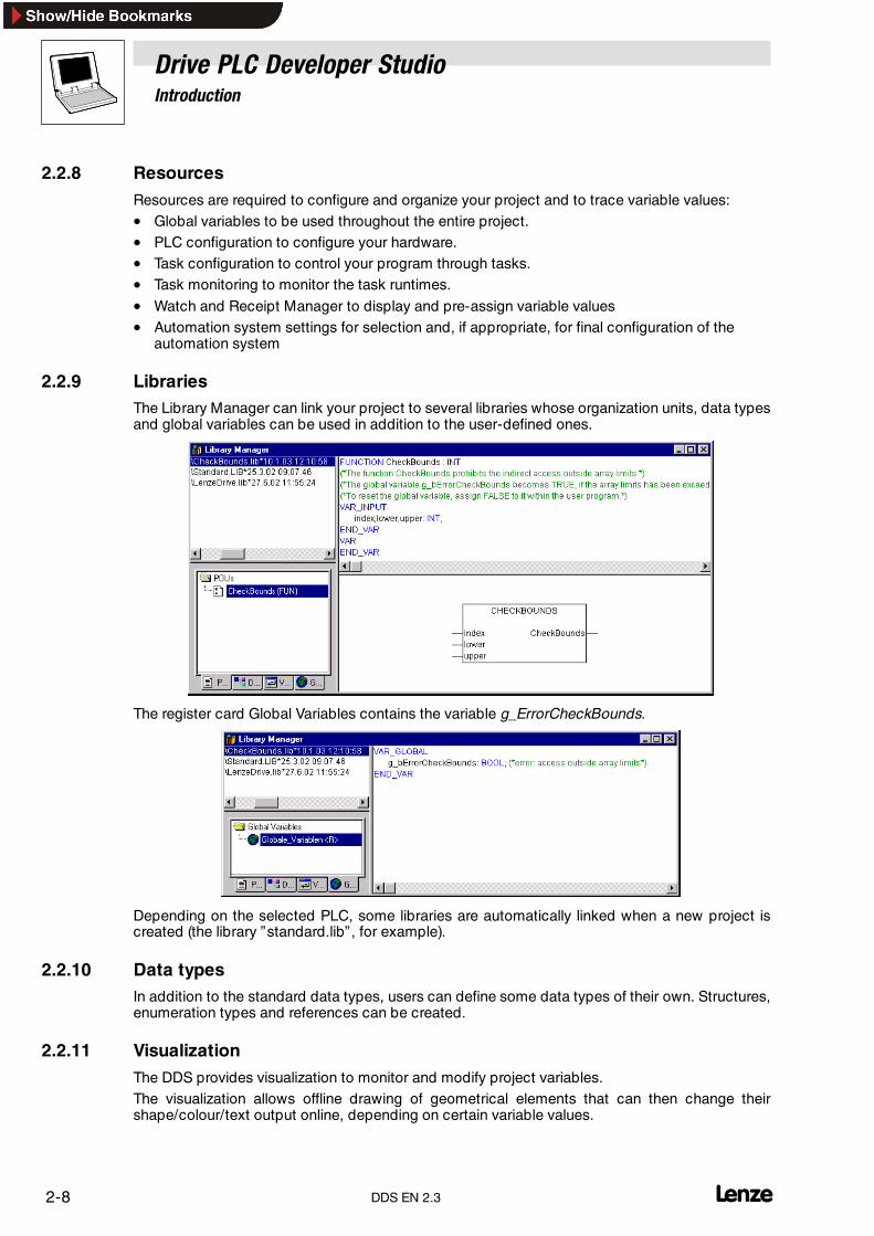
2.2.9 LibrariesThe Library Manager can link your project to several libraries whose organization units, data typesand global variables can be used in addition to the user-defined ones.
The register card Global Variables contains the variable g_ErrorCheckBounds.
Depending on the selected PLC, some libraries are automatically linked when a new project iscreated (the library ”standard.lib” , for example).
2.2.10 Data typesIn addition to the standard data types, users can define some data types of their own. Structures,enumeration types and references can be created.
2.2.11 VisualizationThe DDS provides visualization to monitor and modify project variables.The visualization allows offline drawing of geometrical elements that can then change theirshape/colour/text output online, depending on certain variable values.

Drive PLC Developer StudioIntroduction
2-9l DDS EN 2.3
2.3 Debugging, online functionality
2.3.1 Debugging
The DDS debugging functions assist troubleshooting.
• To allow debugging, go to dialog box Options, category Build options and tick check boxDebugging.
Note!The check box Debugging should be ticked for debugging only.
Breakpoint on, Single step or Single cycle are possible only if Debugging is active.
2.3.2 Breakpoint
A breakpoint is a point in the program where processing stops.
• Breakpoints enable the user to look at variable values at a certain program location.
• Breakpoints can be set in all editors. In the text editors, breakpoints are set to line numbers,in FBD and LD to network numbers, in CFC to organization units, and in SFC to steps.
• Breakpoints may be set in the implementation of an initialized function block. No breakpointsmay be set in function block instances.
2.3.3 Single step
Single step means in:
• IL: Execute program to next CAL, LD or JMP command.
• ST: Execute next instruction.
• FBD, LD: Execute next network.
• SFC: Execute action to next step.
• CFC: Execute next organization unit (box) in the CFC program.
The logical correctness of a program can be checked by step-by-step processing.
2.3.4 Single cycle
Selection of Single cycle will stop processing after every cycle.
Caution!If abreakpoint is set, theuseof tasks will lose the real-time response. A1ms-cycle task will no longerbe started every millisecond.If breakpoints are set, all tasks will be started one after the other after the main program PLC_PRGhas been processed. Event-controlled tasks will be started upon a valid start event only.This, among other aspects, influences the functionality of the generated overall project.
Drive PLC Developer StudioIntroduction
2-10 lDDS EN 2.3
2.3.5 Changing values online
Variables can be set once-only to a specific value during operation after the command Write valueswas transmitted to the control. The value of a variable can also be changed online by simplydouble-clicking it. Boolean variables thus change from TRUE to FALSE and viceversa. For the othervariables, the system will display a dialog box Write variable xy to edit the variable value.
2.3.6 Monitoring
In online mode, the current values for all variables displayed on screenwill becontinuously read fromthe control and displayed. Refer declaration and program editor for this display.
Current variable values may be output in the Watch and Receipt Manager and in a visualization.
The display and monitoring of variables from function block instances requires the associatedinstance to be opened.
The implementations show the pointer value. The dereferenced value is shown for dereferencedvariables.
Monitoring VAR_IN_OUT variables
When monitoring VAR_IN_OUT variables, the de-referenced value is output in the declaration partand the program part.
Monitoring Pointers
Warning!Monitoring of de-referenced pointer values is not supported by all Lenze target systems.
In online mode, it depends on the target system which de-referenced pointer values (pointervariable^ ) are indicated.
Some Lenze target systems indicate the pointer value itself.
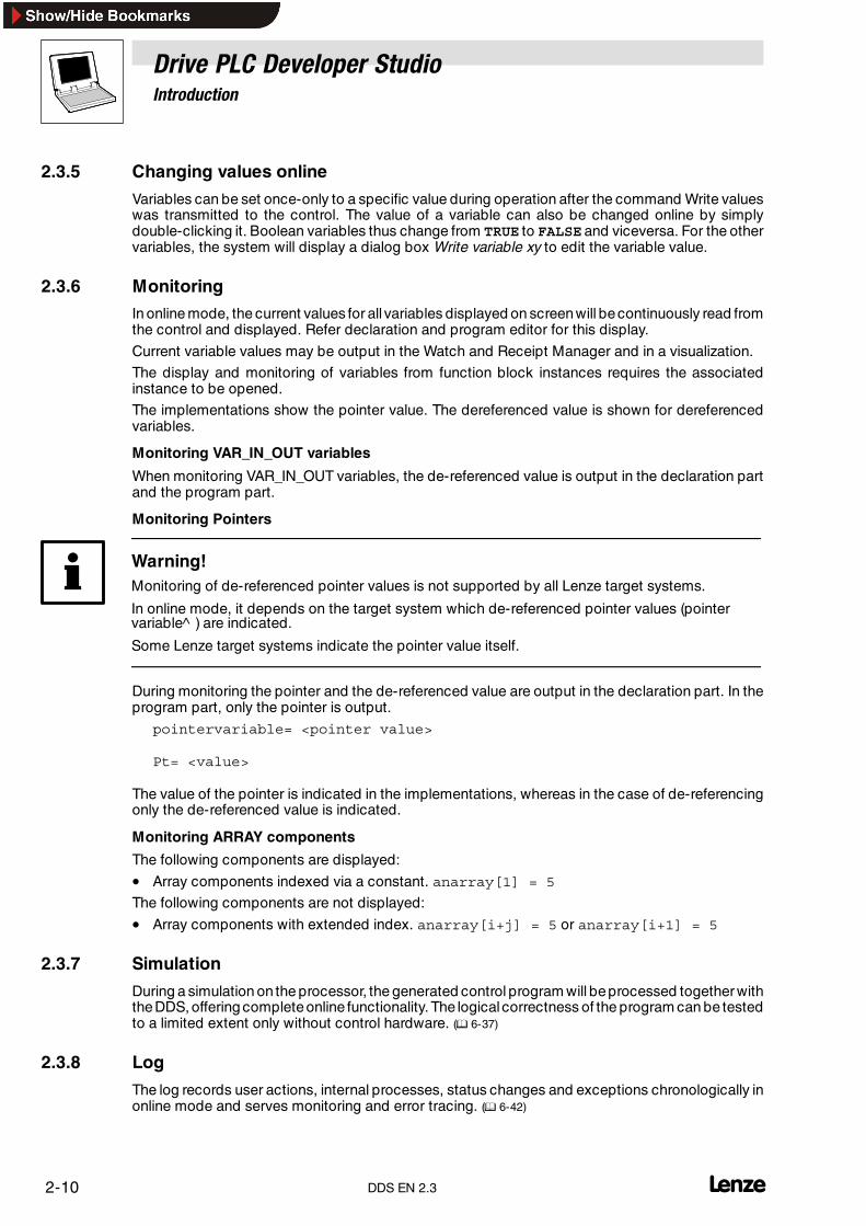
During monitoring the pointer and the de-referenced value are output in the declaration part. In theprogram part, only the pointer is output.
pointervariable= <pointer value>
Pt= <value>
The value of the pointer is indicated in the implementations, whereas in the case of de-referencingonly the de-referenced value is indicated.
Monitoring ARRAY components
The following components are displayed:
• Array components indexed via a constant. anarray[1] = 5
The following components are not displayed:
• Array components with extended index. anarray[i+j] = 5 or anarray[i+1] = 5
2.3.7 Simulation
During a simulation on the processor, the generated control program will beprocessed together withtheDDS, offering completeonline functionality. The logical correctness of the program can be testedto a limited extent only without control hardware. (� 6-37)
2.3.8 Log
The log records user actions, internal processes, status changes and exceptions chronologically inonline mode and serves monitoring and error tracing. (� 6-42)

Drive PLC Developer StudioProgram example
3-1l DDS EN 2.3
3 Program example “Traffic light”
3.1 Introduction
This chapter includes a program tutorial for an easier start with the DDS.
The setup calls for the programming of a mini traffic control system for two traffic lights at anintersection.
• Both traffic lights will alternate their red/green phases.
• To avoid accidents, the traffic lights will also include amber and amber/red between the redand green phases, with the amber/red phase being shorter than the amber phase.
This example illustrates
• how to implement time-controlled programs using IEC 61131-3 language tools.
• how to edit the various standard languages using the DDS.
• how to link the different languages.
• how to simulate a program in the DDS and visualize it on screen.
Drive PLC Developer StudioProgram example
3-2 lDDS EN 2.3
3.2 Programming
3.2.1 Starting the DDS
1. In the Windows Start menu, select submenuPrograms����Lenze�Drive PLC Developer Studio and click Drive PLC Developer Studio tostart the DDS.
Tip!If under Project����Options, category Load & Save, the check box Automatic loading is selected,the project last edited is opened automatically on DDS start.
3.2.2 Creating a new project
2. Select File����New to create a new project.
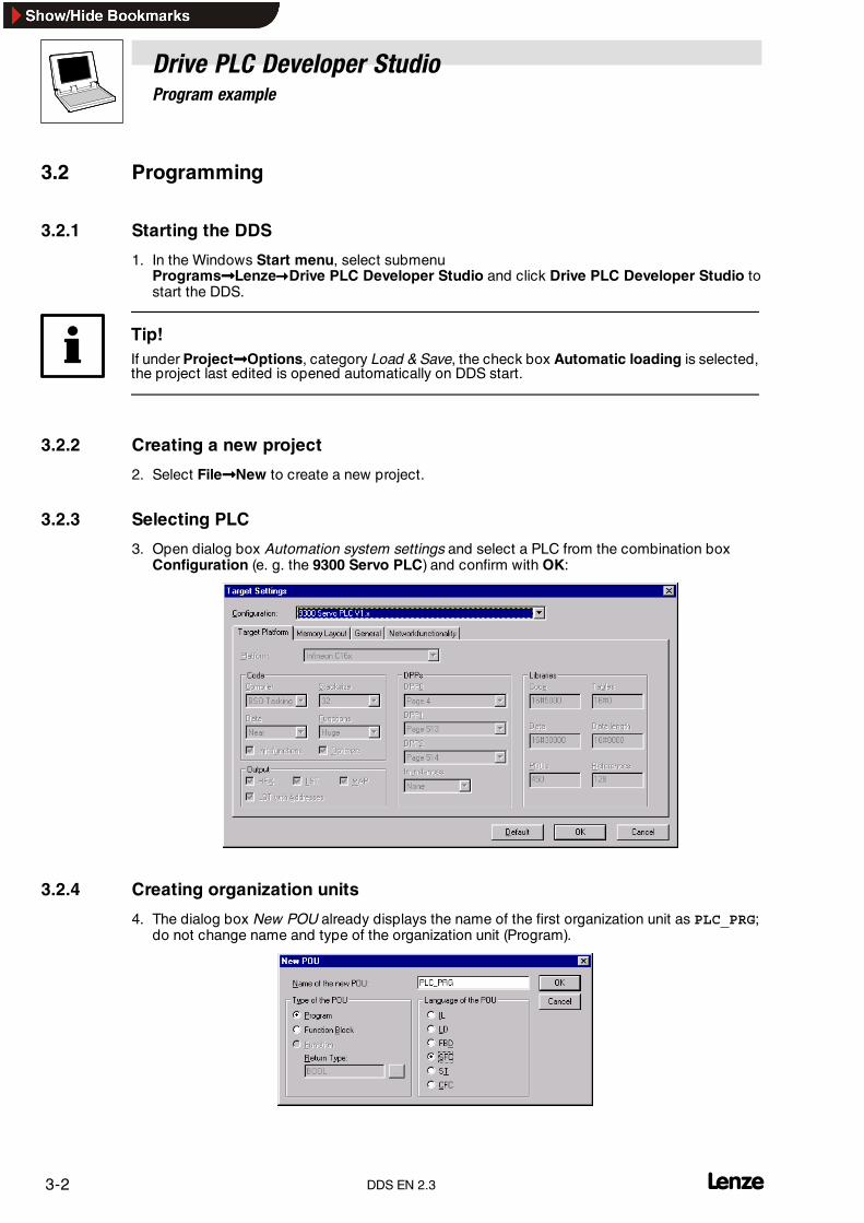
3.2.3 Selecting PLC
3. Open dialog box Automation system settings and select a PLC from the combination boxConfiguration (e. g. the 9300 Servo PLC) and confirm with OK:
3.2.4 Creating organization units
4. The dialog box New POU already displays the name of the first organization unit as PLC_PRG;do not change name and type of the organization unit (Program).

Drive PLC Developer StudioProgram example
3-3l DDS EN 2.3
Tip!Only the organization unit named PLC_PRGof type “Program” will beprocessed by the cyclical task.The cyclical task does not need to be explicitly created.
5. Select Sequential function chart (SFC) as the language for this organization unit andconfirm with OK.
6. Now create two further objects in the Object Organizer on tab Organization units with the helpof Project����Object�Insert:– TRAFFICLIGHT type Function block in the language Function block diagram (FBD)– WAIT type Function block in the language Instruction list (IL)
TRAFFICLIGHT
In the organization unit TRAFFICLIGHT, the individual light phases will be assigned to the trafficlights, i. e., the red light will be on during the red and amber/red phases, the amber light will be onduring the amber and amber/red phases, etc.
WAIT
In the organization unit WAIT, a simple timer will be programmed to receive as input the phaseduration in milliseconds and to return an output TRUE as soon as the time has expired.
PLC_PRG
The organization unit PLC_PRG links the organization units with each other so that the traffic lightemits the correct colour at the correct time and for the specified time. It processes the entire projectduring the cyclical task.
3.2.5 The organization unit TRAFFICLIGHT
7. To edit the organization unit TRAFFICLIGHT, activate its editor window by selectingObject Organizer, tab Organization units and double-clicking TRAFFICLIGHT.
3.2.5.1 Declaration
8. In the declaration editor, declare– as input variable (between the keywords VAR_INPUT and END_VAR) a variable namedSTATE of type INT.
– as output variables (between the keywords VAR_OUTPUT and END_VAR) the variables RED,AMBER, GREEN and OFF of type BOOL.

Drive PLC Developer StudioProgram example
3-4 lDDS EN 2.3
Thestatus of thevariableSTATE is used to switch theoutput variables for theassociated light colour:
Traffic light phase Input variable Output variables
STATE RED AMBER GREEN OFF
Green 1 FALSE FALSE TRUE FALSE
Amber 2 FALSE TRUE FALSE FALSE
Red 3 TRUE FALSE FALSE FALSE
Amber/red 4 TRUE TRUE FALSE FALSE
Off 5 FALSE FALSE FALSE TRUE
The declaration part of the function block TRAFFICLIGHT now looks as follows:
3.2.5.2 Function block diagram
Now use the input variable STATE of the organization unit to determine the values of the outputvariables.
9. In the lower half of the editor window for the organization unit TRAFFICLIGHT, click the fieldto the left of the first network (grey field with number 1) to select the network.
10.Select Insert����Operator.
A box with the operator AND and two inputs is inserted in the first network:
11.Click “AND” and change the text to “EQ” .
12.Select the text “???” of the upper input and enter the variable STATE .
13.Select the three bottom question marks and name the input 1.
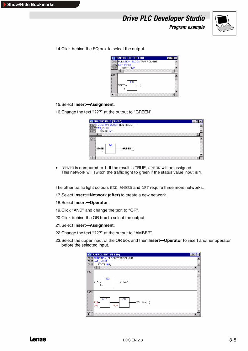
Drive PLC Developer StudioProgram example
3-5l DDS EN 2.3
14.Click behind the EQ box to select the output.
15.Select Insert����Assignment.
16.Change the text “???” at the output to “GREEN” .
• STATE is compared to 1. If the result is TRUE, GREEN will be assigned.This network will switch the traffic light to green if the status value input is 1.
The other traffic light colours RED, AMBER and OFF require three more networks.
17.Select Insert����Network (after) to create a new network.
18.Select Insert����Operator.
19.Click “AND” and change the text to “OR” .
20.Click behind the OR box to select the output.
21.Select Insert����Assignment.
22.Change the text “???” at the output to “AMBER” .
23.Select the upper input of the OR box and then Insert����Operator to insert another operatorbefore the selected input.

Drive PLC Developer StudioProgram example
3-6 lDDS EN 2.3
24.Use the above procedures and commands to complete the organization unit as follows:
The first organization unit is complete. TRAFFICLIGHT controls the traffic light colours dependingon the input of value STATE.
3.2.6 The organization unit WAIT
The organization unit WAIT is to be a timer to control the duration of the different traffic light phases.
25.To edit the organization unit WAIT, activate its editor window by selecting Object Organizer,tab Organization units and double-clicking WAIT.
3.2.6.1 Declaration
26.In the declaration editor, declare– as input variable (between the keywords VAR_INPUT and END_VAR) a variable namedSETTIME of type TIME.
– as output variable (between the keywords VAR_OUTPUT and END_VAR) a variable namedOK of type BOOL.
27.Pre-assign the output variable OK with FALSE by inserting “ :=FALSE” at the end of thedeclaration (but before the ;).
The output variable OK is to output the value TRUE as soon as the time specified with SETTIME hasexpired. For this function use the organization unit TP, a pulse encoder.

Drive PLC Developer StudioProgram example
3-7l DDS EN 2.3
Pulse encoder TP
The pulse encoder TP has two inputs ( IN, PT) and two outputs ( Q, ET).
• If at the input IN TRUE is applied, the output Q , for the time PT (in milliseconds) will return thevalue TRUE.
• ET outputs the time already expired in milliseconds.
Input variable Status Output variables Status/valueIN FALSE Q FALSE
ET 0IN TRUE Q TRUE(ET < PT) ET 0 � PT*IN Q FALSE(ET = PT) ET PT
* The output ET counts the time in milliseconds.
To use the pulse encoder TP in the organization unit WAIT we must create a local instance of TP:
28.Use the declaration editor to declare as local variable (between the keywords VAR andEND_VAR) a variable named DELAY of type TP.
3.2.6.2 Instruction list
To implement the timer, the instruction list for the organization unit WAIT must be as follows:

Drive PLC Developer StudioProgram example
3-8 lDDS EN 2.3
Process
The first interrogation establishes whether Q is already set to TRUE ( TRUE: timer running). [ Line 1]
• If Q is TRUE, we will not change the assignment of DELAY but instead call function blockDELAY without input (to check whether the time has already expired). [ Line 10]
• If Q is FALSE, we will set the variable IN in DELAY to FALSE and thus at the same time ETto 0 and Q to FALSE. [ Line 4]All variables are now set to the desired initial status.– Now save the time required from variable SETTIME in variable PT [ Line 5/6], and call DELAY
with IN:= TRUE. [ Line 7]– In the function block DELAY , the variable ET will now be counted up until it reaches the
value SETTIME ; then Q will be switched to FALSE .
• The negated value of Q will be saved after every WAIT cycle in OK [ Line 14/15]
• As soon as Q becomes FALSE, OK becomes TRUE.
The timer is complete.
3.2.7 The main program PLC_PRG
The organization unit PLC_PRG is the main program for calling the two function blocks WAIT andTRAFFICLIGHT .
29.To edit the organization unit PLC_PRG, activate its editor window by selectingObject Organizer, tab Organization units and double-clicking PLC_PRG .
3.2.7.1 DeclarationTo ensure that the function blocks created before can be used inPLC_PRG , it is necessary to declareinstances of these function blocks. The traffic light example requires two instances of the functionblock TRAFFICLIGHT ( LIGHT1, LIGHT2) and one instance of the function block WAIT ( WAIT1).
30.Use the declaration editor to declare as local variable (between the keywords VAR andEND_VAR) the variables for the required instances.
3.2.7.2 Sequential function chartThe start-up diagram of an organization unit in SFC always consists of an action Init, a subsequenttransition Trans0 and a jump back to Init.

Drive PLC Developer StudioProgram example
3-9l DDS EN 2.3
The traffic light example requires a step for every traffic light phase.
31.Select the transition Trans0 (click the horizontal line to the left of Trans0 ) to frame it with adotted line.
32.Select Insert����Step transition (after) to insert a step transition after Trans0.
33.Repeat the above step seven times to create the following sequential function chart:– To delete a step or transition, select the step and the associated transition, otherwise they
cannot be deleted.– First click the step, press <Shift>, then click the transition.
• Clicking the name of a transition or step directly will invert the text for editing.
34.Change the name of the first transition after Init to TRUE.
35.Change the names of all subsequent transitions to ”WAIT1.OK” .
• The first transition switches all the time, all other transitions when WAIT1 in OK becomesTRUE , i.e. when the specified time has expired.
36.Change the names of the steps as described below (from top to bottom):– Init (remains unchanged)– CHANGE1– GREEN1– CHANGE2– RED1– CHANGE3– GREEN2– CHANGE4– RED2
• ”CHANGEx” stands for a amber phase each time, “GREEN1” means that traffic light 1 will begreen and “GREEN2” applies for traffic light 2, “RED1” means that traffic light 1 will be redand “RED2” applies for traffic light 2.
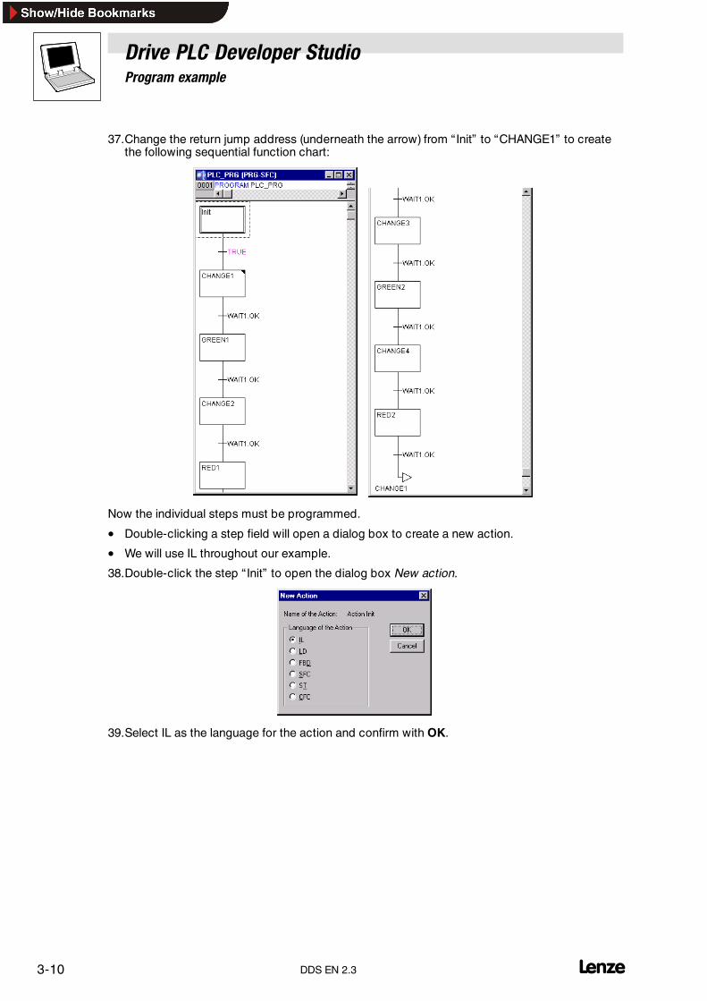
Drive PLC Developer StudioProgram example
3-10 lDDS EN 2.3
37.Change the return jump address (underneath the arrow) from “ Init” to “CHANGE1” to createthe following sequential function chart:
Now the individual steps must be programmed.
• Double-clicking a step field will open a dialog box to create a new action.
• We will use IL throughout our example.
38.Double-click the step “ Init” to open the dialog box New action.
39.Select IL as the language for the action and confirm with OK.

Drive PLC Developer StudioProgram example
3-11l DDS EN 2.3
40.Enter the following actions for the step “ Init” into the editor window and define the actions forthe other steps in the same way.
Step Actions Status Light1/Light2
Init CAL LIGHT1(STATE:=3)CAL LIGHT2(STATE:=3)
CHANGE1 CAL LIGHT1(STATE:=4)CAL LIGHT2(STATE:=3)CAL WAIT1(SETTIME:=t#2s)
GREEN1 CAL LIGHT1(STATE:=1)CAL LIGHT2(STATE:=3)CAL WAIT1(SETTIME:=t#5s)
CHANGE2 CAL LIGHT1(STATE:=2)CAL LIGHT2(STATE:=3)CAL WAIT1(SETTIME:=t#2s)
RED1 CAL LIGHT1(STATE:=3)CAL LIGHT2(STATE:=3)CAL WAIT1(SETTIME:=t#1s)
CHANGE3 CAL LIGHT1(STATE:=3)CAL LIGHT2(STATE:=4)CAL WAIT1(SETTIME:=t#2s)
GREEN2 CAL LIGHT1(STATE:=3)CAL LIGHT2(STATE:=1)CAL WAIT1(SETTIME:=t#5s)
CHANGE4 CAL LIGHT1(STATE:=3)CAL LIGHT2(STATE:=2)CAL WAIT1(SETTIME:=t#2s)
RED2 CAL LIGHT1(STATE:=3)CAL LIGHT2(STATE:=3)CAL WAIT1(SETTIME:=t#1s)
This completes the first phase of our program. You can now compile the program and test it in asimulation.
3.2.8 Extending the program with an alternative branch
To include at least one alternative branch in our chart so that we can turn the traffic lights off overnight, we will include a counter to deactivate thesystem after a specific number of traffic light cycles.
Firstly, we will need a new variable COUNTER of type INT.
41.To edit the organization unit PLC_PRG, activate its editor window by selecting ObjectOrganizer, tab Organization units and double-clicking PLC_PRG .
42.Use the declaration editor to declare as local variable (between the keywords VAR andEND_VAR) the variable COUNTER of type INT.
43.Initialize the variable COUNTER in the step “ Init” with 0:
Step Actions Status Light1/Light2
Init CAL LIGHT1(STATE:=3)CAL LIGHT2(STATE:=3)
LD 0ST COUNTER

Drive PLC Developer StudioProgram example
3-12 lDDS EN 2.3
44.Select the transition after “CHANGE1“ and then Insert����Step transition (after) to insert astep transition.
45.Select the newly new created transition and then Insert����Alternative branch left to insert analternative branch to the left of it.
46.Select the left transition and then Insert����Step transition (after) to insert a step transition.
47.Select the newly new created transition and then Insert����Jump to insert a jump.
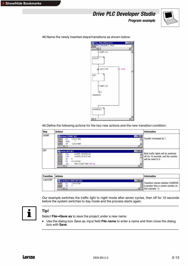
Drive PLC Developer StudioProgram example
3-13l DDS EN 2.3
48.Name the newly inserted steps/transitions as shown below:
49.Define the following actions for the two new actions and the new transition condition:
Step Actions Information
COUNTCounter increased by 1.
OFFBoth traffic lights will be switchedoff for 10 seconds, and the counterwill be reset to 0.
Transition Actions Information
LIGHTOFFTransition checks whether COUNTERis greater than a certain number (inthis example: 7).
Our example switches the traffic light to night mode after seven cycles, then off for 10 secondsbefore the system switches to day mode and the process starts again.
Tip!Select File����Save as to save the project under a new name.
• Use the dialog box Save as, input field File name to enter a name and then close the dialogbox with Save.
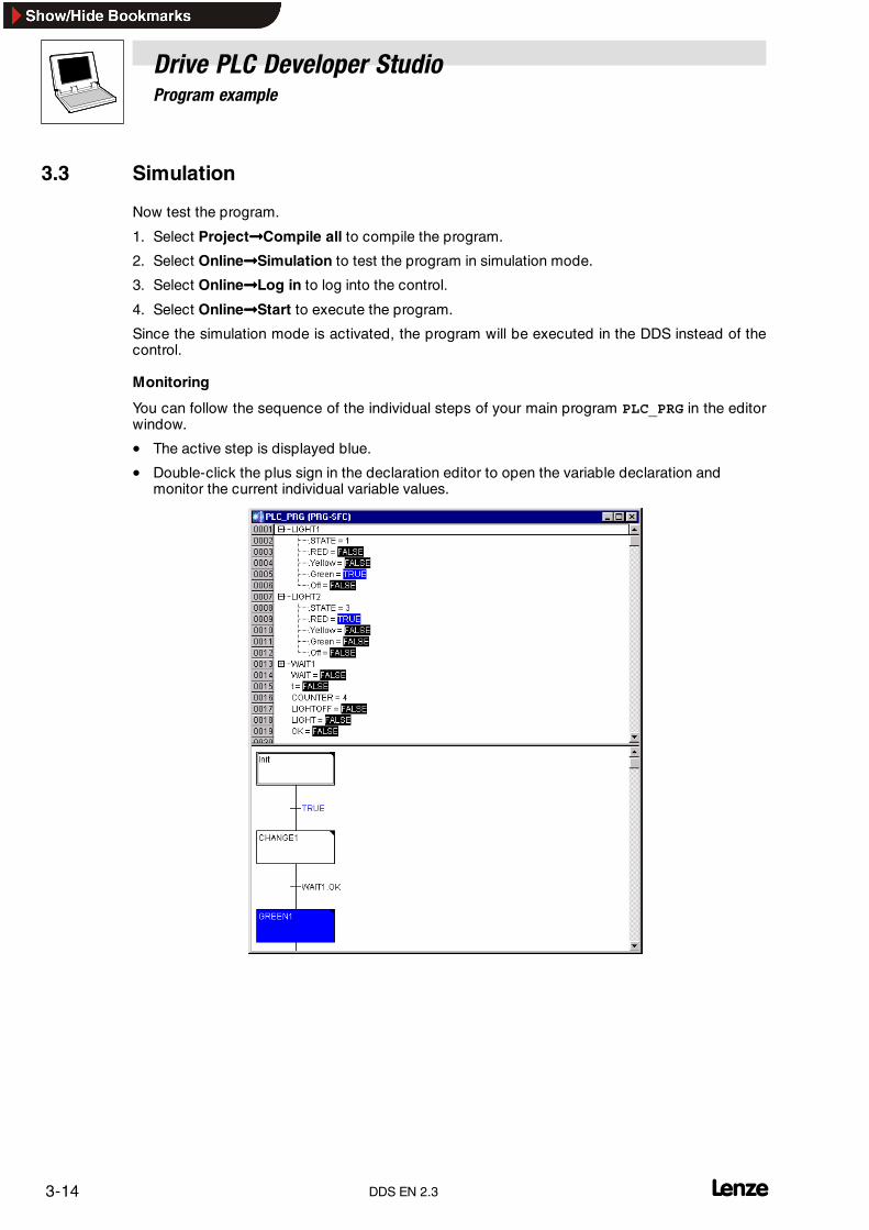
Drive PLC Developer StudioProgram example
3-14 lDDS EN 2.3
3.3 Simulation
Now test the program.
1. Select Project����Compile all to compile the program.
2. Select Online����Simulation to test the program in simulation mode.
3. Select Online����Log in to log into the control.
4. Select Online����Start to execute the program.
Since the simulation mode is activated, the program will be executed in the DDS instead of thecontrol.
Monitoring
You can follow the sequence of the individual steps of your main program PLC_PRG in the editorwindow.
• The active step is displayed blue.
• Double-click the plus sign in the declaration editor to open the variable declaration andmonitor the current individual variable values.
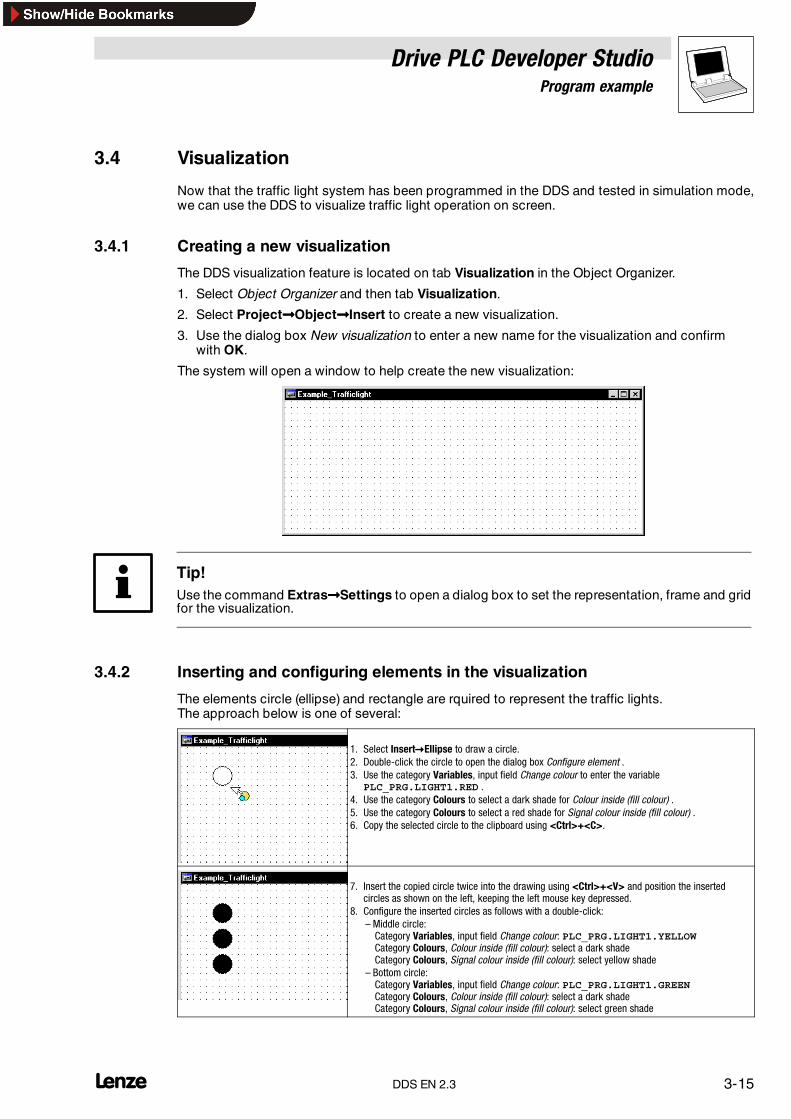
Drive PLC Developer StudioProgram example
3-15l DDS EN 2.3
3.4 Visualization
Now that the traffic light system has been programmed in the DDS and tested in simulation mode,we can use the DDS to visualize traffic light operation on screen.
3.4.1 Creating a new visualization
The DDS visualization feature is located on tab Visualization in the Object Organizer.
1. Select Object Organizer and then tab Visualization.
2. Select Project����Object����Insert to create a new visualization.
3. Use the dialog box New visualization to enter a new name for the visualization and confirmwith OK.
The system will open a window to help create the new visualization:
Tip!Use the command Extras����Settings to open a dialog box to set the representation, frame and gridfor the visualization.
3.4.2 Inserting and configuring elements in the visualization
The elements circle (ellipse) and rectangle are rquired to represent the traffic lights.The approach below is one of several:
1. Select Insert�Ellipse to draw a circle.2. Double-click the circle to open the dialog box Configure element .3. Use the category Variables, input field Change colour to enter the variable
PLC_PRG.LIGHT1.RED .4. Use the category Colours to select a dark shade for Colour inside (fill colour) .5. Use the category Colours to select a red shade for Signal colour inside (fill colour) .6. Copy the selected circle to the clipboard using <Ctrl>+<C>.
7. Insert the copied circle twice into the drawing using <Ctrl>+<V> and position the insertedcircles as shown on the left, keeping the left mouse key depressed.
8. Configure the inserted circles as follows with a double-click:– Middle circle:Category Variables, input field Change colour: PLC_PRG.LIGHT1.YELLOWCategory Colours, Colour inside (fill colour): select a dark shadeCategory Colours, Signal colour inside (fill colour): select yellow shade
– Bottom circle:Category Variables, input field Change colour: PLC_PRG.LIGHT1.GREENCategory Colours, Colour inside (fill colour): select a dark shadeCategory Colours, Signal colour inside (fill colour): select green shade

Drive PLC Developer StudioProgram example
3-16 lDDS EN 2.3
9. Select Insert�Rectangle to draw a rectangle over the three circles.10.Double-click the rectangle to open the dialog box Configure element .11.Use the category Colours to select a dark grey shade for Colour inside (fill colour).12.Select Extras�To the background to put the rectangle behind the circles.
13.Use the mouse pointer to draw a frame around the elements to select all elements within theframe.
14.Copy the selected elements to the clipboard using <Ctrl>+<C>.
15.Insert the copied elements into the drawing using <Ctrl>+<V> and position the insertedelements as shown on the left, keeping the left mouse key depressed.
16.Configure the three circles of the traffic light on the right as follows with a double-click:– Upper circle:Category Variables, input field Change colour: PLC_PRG.LIGHT2.RED
– Middle circle:Category Variables, input field Change colour: PLC_PRG.LIGHT2.YELLOW
– Bottom circle:Category Variables, input field Change colour: PLC_PRG.LIGHT2.GREEN
17.Select Insert�Rectangle to draw a rectangle underneath each traffic light.18.Configure the rectangles as follows with a double-click:
– Use the category Colours to select No frame colour.– Use the category Text to enter a text for each traffic light(example: “LIGHT1” and “LIGHT2”).
3.4.3 Visualization in online mode
Restart the program, and the traffic lights will be ”on” in the visualization for the specified times,and correct functioning of the traffic control system can be very simply tested.
Tip!For a detailed description of the visualization process refer chapter (� 9-1)

Drive PLC Developer StudioProgramming languages
4-1l DDS EN 2.3
4 Programming languages
4.1 The standard IEC 61131-3
The standard IEC 61131-3 is an international standard for PLC programming languages.
The programming languages implemented in the DDS are in conformity with therequirements of this standard.
According to this standard, a program consists of the following elements:
• Structures
• Organization units
• Global variables
• Local variables
• Configuration
• etc.

Drive PLC Developer StudioProgramming languages
4-2 lDDS EN 2.3
4.2 Instruction list (IL)
An instruction list (IL) consists of a sequence of instructions.
• Each instruction starts with a new line, contains an operator and - depending on the type ofoperation - one or several comma-separated operands.
• An instruction may be preceded by a jump label followed by a colon (;).
• Additional comments can be entered.
• Blank lines may be inserted between instructions.
• All commands are saved in an accumulator where intermediate results and the result of thelast command are stored.
Example:
LD 17ST lint (* comment *)GE 5JMPC nextLD idwordEQ istruct.sdwordSTN testnext:
4.2.1 Operators and modifiers
The following operators and modifiers can be used in IL.
Modifiers
• C: conditional for JMP, CAL, RET:The instruction will only be carried out if the result of the preceding expression is TRUE.
• N for JMPC, CALC, RETC:The instruction will only be carried out if the result of the preceding expression is FALSE.
• N otherwiseNegation of the operand (not of the accumulator).

Drive PLC Developer StudioProgramming languages
4-3l DDS EN 2.3
The table lists some IL operators along with possible modifiers and their respective meaning:
Operator Modifiers Meaning
LD N (=”NOT”) Load Load instruction
ST N Store Save the current result in the operand location
S Set Set Boolean operand to TRUE exactly if the current result is TRUE.
R Reset Set Boolean operand to FALSE exactly if the current result is TRUE.
AND N,( Bit-by-bit AND
OR N,( Bit-by-bit OR
XOR N,( Bit-by-bit exclusive OR
ADD ( Addition
SUB ( Subtraction
MUL ( Multiplication
DIV ( Division
GT ( > Greater than
GE ( >= Greater than or equal to
EQ ( = Equal to
NE ( <> Not equal to
LE ( <= Less than or equal to
LT ( < Less than
JMP/JMPC N Jump Jump to label
CAL/CALC N Call Call program or function block
RET/RETC N Return Return from calling a function block
) Evaluate operation that has been deferred
For a more comprehensive IEC operator list refer chapter 12.
Example
IL program using several modifiers
LD TRUE (* Load TRUE to the accumulator *)ANDN BOOL1 (* Execute AND with the negated valueof the variable BOOL1 *)JMPC label (* If the result was TRUEjump to the label “label” *)LDN BOOL2 (* save the negated value of *)ST ERG (* BOOL2 in ERG *)
Label:LD BOOL2 (* save the value of *)ST ERG (* BOOL2 in ERG *)
IL also allows the setting of parentheses after an operation. The value in parentheses is taken asoperand.
Example 1 Example 2
LD 2 LD 2MUL 2 MUL (2ADD 3 ADD 3
)ST Result ST
• In example 1, the value of Result is 7.
• In example 2 with parentheses the value for Result is 10, because the operation MUL willonly be evaluated on reaching ”)” ; the operand for MUL is 5.

Drive PLC Developer StudioProgramming languages
4-4 lDDS EN 2.3
4.3 Structured text (ST)
Structured text consists of a series of instructions that can be executed as conditioned in veryhigh-level languages (IF..THEN..ELSE)or in loops (WHILE..DO). An instruction is completed witha semicolon;.
Example:
IF value < 7 THENWHILE value < 8 DOvalue := value + 1;END_WHILE;END_IF;
4.3.1 Expressions
An expression returns a value on evaluation and consists of operators and operands.
An operand can be
• a constant,
• a variable,
• a function call
• or another expression.
4.3.2 Evaluating expressions
Expressions are evaluated by processing operators following certain priorities. Operators with thehighest priority are processed first followed by operators with the second highest priority and so on,until all operators are processed. Same-priority operators are processed from left to right.
The following table lists ST operators in the order of their priority.
Operation Symbol Priority (ranking)
Parentheses (Expression) Highest priorityFunction call Function name (parameter list)
Exponentiation EXPT
Negation -
Complementation NOT
Multiplication *
Division /
Modulo MOD
Addition +
Subtraction -
Compare <, >, <=, >=
Equal to =
Not equal to <>
Bool AND AND
Bool XOR XOR
Bool OR OR Lowest priority

Drive PLC Developer StudioProgramming languages
4-5l DDS EN 2.3
4.3.3 Instructions (overview)
The following instructions are available in ST:
Instruction type Example
Assignment by assignment operator A:=B;CV:=CV + 1;C:=SIN(X);
Function block calluse of the FB output
CMD_TMR(IN:=%IX1.0.1, PT:=T#300ms);A:=CMD_TMR.Q
RETURN RETURN;
IF condition D:=B*B;IF D<0.0 THENC:=A;
ELSIF D=0.0 THENC:=B;
ELSEC:=D;
END_IF;
CASE s election CASE INT1 OF1: BOOL1:=TRUE;2: BOOL2:=TRUE;
ELSEBOOL1:=FALSE;BOOL2:=FALSE;END_CASE;
FOR loop J:=101;FOR I:=1 TO 100 BY 2 DOIF ARR[I]=70 THENJ:=I;EXIT;
END_IF;END_FOR;
WHILE loop J:=1;WHILE J<=100 AND ARR[J]<>70 DOJ:=J+2;
END_WHILE;
REPEAT loop J:=-1;REPEATJ:=J+2;UNTIL J= 101 OR ARR[J]=70END_REPEAT;
EXIT EXIT;
Dummy instruction ;
4.3.4 Assignment operator
The value of the expression on the right-hand side of an assignment is assigned to an operand(variable, address) on the left-hand side of an assignment by using the assignment operator :=.
Example:
Var1 := Var2 * 10;
After this line has been executed Var1 is ten times the value of Var2.

Drive PLC Developer StudioProgramming languages
4-6 lDDS EN 2.3
4.3.5 Calling a function block in ST
A function block in ST is called by using the name of the function block instance followed byparentheses in which the parameters are assigned the required values.
Example
• A timer is called with assignments for parameters IN and PT:
CMD_TMR(IN := %IX1.0.1, PT := T#300);
• The result variable Q is then assigned to variable A:
A:=CMD_TMR.Q
• As in IL, the result variable is addressed using the function block name followed by a periodand the variable name.
4.3.6 RETURN instruction
The RETURN instruction is used to complete the processing of the organization unit and to return tothe calling organization unit, depending on a condition, for instance.
4.3.7 IF instruction
Use the IF instruction to check a condition. Instructions can be executed depending on thiscondition.
Syntax:
IF <Boolean_expression1> THEN<IF_instructions>{ELSIF <Boolean_expression2> THEN<ELSIF_instructions1>...ELSIF <Boolean_expression n> THEN<ELSIF_instructions n-1>ELSE<ELSE_instructions>}END_IF;
• The part in curly brackets {} is optional.
• If <Boolean_expression1> returns TRUE, only <IF_instructions> will beexecuted.
• Otherwise the Boolean expressions starting with <Boolean_expression2> will be evaluatedone after the other until one of the expressions returns TRUE. Then only the instructions afterthis Boolean expression and before the next ELSE or ELSIF will be evaluated.
• If none of the Boolean expressions is TRUE, only the <ELSE_instructions> will beevaluated.
Drive PLC Developer StudioProgramming languages
4-7l DDS EN 2.3
Example:
IF temp < 17 THENheating_on:=TRUE;ELSEheating_on:=FALSE;END_IF;
In this example the heating is switched on only if the temperature falls below 17 degrees Centigrade,otherwise the heating will remain off.
4.3.8 CASE instruction
Use the CASE instruction to aggregate several conditional instructions with the same conditionalvariable.
Syntax:
CASE <Var1> OF<Value 1>:<instruction 1><Value 2>:<instruction 2>...<Value n>:<instruction n>ELSE<ELSE instruction>END_CASE;
A CASE instruction is processed as described below:
• If the variable in <Var1> is set to <Value i>, the instruction <instruction i> will beexecuted.
• If <Var 1> does not equal one of the specified values, the <ELSE instruction> will beexecuted.
• If the same instruction is to be executed for several variable values, these values can becomma-separated to indicate that they are linked to the same instruction.
• If the same instruction is to be executed for a value aggregate of the variable, the start andend values can be separated by two successive periods to indicate that they are linked to thesame instruction.
Example:
CASE INT1 OF1,5:BOOL1:=TRUE;BOOL3:=FALSE;2:BOOL2:=FALSE;BOOL3:=TRUE;10..20:BOOL1:=TRUE;BOOL3:=TRUE;ELSEBOOL1:=NOT BOOL1;BOOL2:=BOOL1 OR BOOL2;END_CASE;

Drive PLC Developer StudioProgramming languages
4-8 lDDS EN 2.3
4.3.9 FOR loop
Use the FOR loop to program repetitive procedures.
Syntax:
INT_Var :INT;
FOR <INT_Var>:=<INIT_VALUE> TO <END_VALUE> {BY <step size>} DO<instructions>END_FOR;
• The part in curly brackets {} is optional.
• The <instructions> are executed as long as the counter<INT_Var> is not greater thanthe<END_VALUE>.
• A check is performed before the <instructions> are executed so that the<instructions> will never be executed if <INIT_VALUE> is greater than <END_VALUE>.
• Whenever the section <instructions> has been executed, <INT_Var> will be increasedby <step size>.
• The step size can have any integer value. If no other step size is specified, step size 1 will beused. The loop must terminate because <INT_Var> will only become greater.
• If <INIT_VALUE> is greater than <END_VALUE> and <step size> is negative, the FORloop is counted in opposite direction.
• If <INIT_VALUE> is less than <END_VALUE> and <step size> is negative, the FOR loopwill not be executed.
Example:
FOR Counter:=1 TO 5 BY 1 DOVar1:=Var1*2;END_FOR;Res:=Var1;
Assuming that the variable Var1 has been pre-assigned value 1, it will be 32 after the FOR loop.
Caution!<END_VALUE> must not be the limit value of the counter <INT_VAR>.
If, for instance, the variable Counter is of type SINT, <END_VALUE> must not be 127 sinceotherwise the loop would be endless.
After completion of the FOR loop, Counter has a value 6.
Drive PLC Developer StudioProgramming languages
4-9l DDS EN 2.3
4.3.10 WHILE loop
The WHILE loop can be used like a FOR loop, the only difference being that the cancel condition canbe any Boolean expression.
Syntax:
WHILE <Boolean expression> DO<instructions>END_WHILE;
• The <instructions> will be executed again and again until the<Boolean_expression> returns TRUE.
• If <Boolean_expression> is FALSE on first evaluation already, the <instructions> willnever be executed.
• If <Boolean_expression> is never FALSE the <instructions> will be repeatedendlessly, forcing a runtime error.
Note!The programmer himself must ensure that endless loops do not occur by changing the conditionin the instruction part of the loop, for instance change the counter settings. Otherwise the task withthe endless loop would overflow.
Example:
WHILE Counter<>0 DOVar1:=Var1*2;Counter:=Counter-1;END_WHILE
The WHILE and the REPEAT loops are more powerful in a way than the FOR loop since the numberof loop cycles does not need to be known prior to loop execution.
In some cases, these two loop types will have to be sufficient.
If the number of loop cycles is known, however, a FOR loop should be preferred.
Task overflows can also occur in FOR loops. (� 4-8)

Drive PLC Developer StudioProgramming languages
4-10 lDDS EN 2.3
4.3.11 REPEAT loop
The REPEAT loop differs from the WHILE loop in that the cancel condition will only be checked afterthe loop has been carried out. This means that the loop must be executed at least once no matterwhat the cancel condition is.
Syntax:
REPEAT<instructions>UNTIL <Boolean expression>END_REPEAT;
• The <instructions> are executed until <Boolean expression> returns TRUE.
• If <Boolean expression> returns TRUE on first evaluation already, the<instructions> will be executed exactly once.
• If <Boolean_expression> is never TRUE, the <instructions> will be repeatedendlessly, forcing a runtime error.
Example:
REPEATVar1:=Var1*2;Counter:=Counter-1;UNTILCounter=0END_REPEAT;
4.3.12 EXIT instruction
If the EXIT instruction is part of a FOR-, WHILE or REPEAT loop, the loop will be terminatedirrespective of the cancel condition.
In nested loops, EXIT terminates the innermost loop.

Drive PLC Developer StudioProgramming languages
4-11l DDS EN 2.3
4.4 Sequential Function Chart (SFC)
Sequential Function Chart is a graphically oriented language that enables the user to describe thechronological sequence of different actions within a program.
Example of a network in SFC
4.4.1 Step
An organization unit written in SFC consists of a sequence of steps that are interconnected throughtransitions.
There are two different step types:
• The simplified step consist of an action and a flag to indicate whether the step is active ornot. A small triangle appears in the top right-hand corner of the step to indicate that theaction for a step has been implemented.
• An IEC step consists of a flag and one or more assigned actions or Boolean variables. Theassociated actions appear to the right of the step.
4.4.2 Action
An action may contain a sequence of instructions in IL, CFC or ST, a number of networks in FBD orLD or another sequence structure (SFC).
• Simplified steps always have an action linked to the step.
• Actions can be edited by double-clicking the step linked to the action or selecting the stepbefore executing menu command Extras����Zoom action/transition. Furthermore, theconfiguration allows one entry and / or one exit action per step.
• In the Object Organizer, actions of IEC steps are grouped directly underneath their SFCorganization unit and can be loaded into the editor with a double-click or pressing the<Enter> key. New actions can be generated with Project����Add action.

Drive PLC Developer StudioProgramming languages
4-12 lDDS EN 2.3
4.4.3 Entry and exit actionIn addition to the step action, a step may be added an entry action and an exit action.• An entry action is executed once-only immediately after the step has been activated.• An exit action is executed once-only before the step is deactivated.• Entry and exit actions can be implemented in any language.A step with entry action is identified with an ’E’ in the bottom left-hand corner, the exit action withan ’X’ in the bottom right-hand corner.• Double-click the respective corner in the step to edit an entry or exit action.
Example of a step with entry and exit actions:
Note!Any exit action contained in the active step will be executed during the next cycle only, providedthe subsequent transition is TRUE.
4.4.4 Transition/transition conditionThere are so-called transitions between the steps.A transition condition must have a value TRUE or FALSE and can therefore consist of• a Boolean variable• a de-referenced address to Boolean variable (poTo_bTest)• a Boolean constant (TRUE)• a sequence of instructions with a Boolean result in ST syntax
(e.g. (i<=100) AND b)• a sequence of instructions programmed in any languageA transition must not contain any programs, function blocks or assignments.
Tip!The next step can be reached both via transitions and the single step mode.(SFCtip and SFCtipmode)
4.4.5 Active stepThe initial SFC editor call always executes the action pertaining to the initial step.
• A step whose action is being executed is referred to as the active step.• In online mode, active steps are displayed in blue.

Drive PLC Developer StudioProgramming languages
4-13l DDS EN 2.3
In a control cycle, all actions belonging to active steps are being executed. The subsequenttransition condition is checked once an active step has been executed. If the transition conditionis met (TRUE), the subsequent step will be executed during the next control cycle.
Step flag
Each step has a flag to save the step status.
Note!A step flag bears the step’s name.
A step and a Boolean variable must not bear the same name as logical errors may otherwise occur.
• The flag does not need to be explicitly declared.
• The step flag (active or inactive step status) is represented by the logical value of a Booleanvariable <StepName>.
• This Boolean variable has a value TRUE if the associated step is active, and FALSE if it is not.This variable is implicitly declared and can be used in any action and transition of the SFCorganization unit.
Time flag
The active time of a step can be interrogated via flag _time <StepName>.
• The flag does not need to be explicitly declared.
• Interrogation works only if a minimum time was set in the step attributes for the step to beinterrogated, for example t#0ms.
4.4.6 IEC step
SFC also offers standard-compliant IEC steps in addition to the simplified steps.
Include the SFC library iecsfc.lib into your project to use IEC steps.
An IEC step can be assigned any number of actions.
• Unlike simplified steps, IEC actions are not firmly assigned to a step as an entry or exit action,but are available separately from the steps and can be applied more than once within theirorganization unit. For this purpose, IEC actions must be linked with the desired steps with thehelp of command Extras����Associate action.
Not only actions but also Boolean variables can be assigned to steps.
• So-called qualifiers control activation and deactivation of actions and Boolean variables, alsopermitting time delays.
• Concurrences may occur since an action may still be active even if the next step may alreadybe processed, via qualifier S (Set), for example.
Associated Boolean variables are set or reset on each SFC organization unit call, i. e. it is reassignedeither the value TRUE or FALSE each time.
The actions associated with an IEC step are displayed in a split box to the right of the step. Theleft-hand field contains the qualifier (if necessary with time constants), the right-hand field the nameof the action or the Boolean variable.

Drive PLC Developer StudioProgramming languages
4-14 lDDS EN 2.3
Example of a two-action IEC step:
• For easier monitoring of the processes, all active actions, like active steps, are displayed inblue in online mode. Which actions are active, is checked after every cycle.
• Whether a newly inserted step is an IEC step is dependent on whether menu commandExtras����Use IEC steps has been selected.
Note!Note restriction on the use of time qualifiers for actions used more than once within the same cycle.
Following a call, the deactivated actions are processed first before all active actions, both inalphabetical sequence.
In the Object Organizer, the actions are attached directly under the associated SFC organizationunit:
• New actions can be generated with Project����Add action.
4.4.7 Qualifiers
The following qualifiers are available to associate actions to IEC steps:
N Non-stored The action is active as long as the step is active.
R overriding Reset The action is deactivated.
S Set (Stored) The action is activated and remains active until reset.
L time Limited The action is active for a certain period of time but no longer than the step is active.
D time Delayed The action will become active after a certain period of time, as long as the step is still active, andthen as long as the step remains active.
P Pulse The action is executed exactly once-only when the step becomes active.
SD Stored and time Delayed The action is activated after a certain period of time and remains active until reset.
DS Delayed and Stored The action is activated after a certain period of time as long as the step is still active, and remainsactive until reset.
SL Stored and time Limited The action is active for a certain period of time.
• The qualifiers L, D, SD, DS and SL require a time specification in TIME constant format,e.g. L T#5s.
Drive PLC Developer StudioProgramming languages
4-15l DDS EN 2.3
Note!When an action is deactivated, it will be executed once again. This means that every action isexecuted at least twice (even actions with qualifier P).
If the same action is applied in two directly successive steps with time-affecting qualifiers, the timequalifier will not be effective on second use. To avoid this behaviour, insert an intermediate step toallow re-initialization of the action status in the additional cycle that must then be run.
4.4.8 Implicit SFC variables
SFC provides implicitly declared variables for use.
• The step flag (active or inactive step status) is called <StepName>.x for IEC steps.
• This Boolean variable has a value TRUE if the associated step is active, and FALSE if it is not.This variable is implicitly declared and can be used in any action and transition of the SFCorganization unit.
• Whether an IEC action is active or not can be interrogated with the help of variable<ActionName>.x. During the IEC action deactivation run, this variable already holds a valueFALSE.
• With IEC steps, the implicit variable <StepName>.t can be used to interrogate the activetime of a step.Interrogation works only if a minimum time was set in the step attributes for the step to beinterrogated, for example t#0ms.
4.4.9 SFC flags
SFC flags are for step control and must be globally or locally declared.
Flag variables and their properties
SFCEnableLimit
This specific variable is a BOOL-type variable. If TRUE, the process registers step timeouts inSFCErrorand otherwise ignores them. This applicationmay beuseful for commissioning or manualoperation, for example.
SFCInit
If this variable is TRUE, the SFC and the other flags are reset to the init step (initialization). As longas the variable is TRUE, the init step remains set without being executed. If SFCInit is reset toFALSE, the organization unit will be processed further.
SFCReset
This BOOL-type variable behaves similarly to SFCInit. Although the init step is processed furtherfollowing initialization. This behaviour may be used to set the SFCReset flag in the init stepimmediately back to FALSE.
Note!SFCInit and SFCReset cannot be used simultaneously in one organization unit. SFCInit willalways have priority.

Drive PLC Developer StudioProgramming languages
4-16 lDDS EN 2.3
Example of a declaration
PROGRAM flagsVARSFCEnableLinit:BOOL;SFCError:BOOL;SFCErrorStep:STRING;SFCReset AT %IX1.0.2: BOOL;SFCInit AT %IX1.0.3:BOOL;END_VAR
SFCQuitError
Processing of the SFC diagram will be suspended for as long as this Booleanvariable remainsTRUE.Timeouts invariablesSFCErrorwill be reset. All previous times in the activesteps will be reset whenthe variable is reset to FALSE.
SFCPause
Processing of the SFC diagram will be suspended for as long as this Booleanvariable remainsTRUE.
SFCError
This Boolean variable becomesTRUE if a timeout occurred in an SFC diagram. If variableSFCErroris not reset again, and the first timeout is then followed by a second one in the program, the secondone will not be registered.
SFCTrans
This Boolean variable becomes TRUE when a transition switches.
SFCErrorStep
This variable is aSTRING-type variable that, ifSFCError registers a timeout, stores the name of thestep that causes the timeout.
SFCErrorPOU
This STRING-type variable, after a timeout, contains the name of the organization unit in which thetimeout occurred.
SFCCurrentStep
This variable is a STRING-type variable that saves the name of the active step independently of thewatchdog function. In parallel branching, the step is saved in the branch at the extreme right.
SFCTip, SFCTipMode
These BOOL-type variables permit the SFC tip mode. If that is activated viaSFCTipMode = TRUE, the next step can be reached only if SFCTip is set to TRUE. As long asSFCTipMode is set to TRUE, the transitions may also be used for switching.
SFCErrorAnalyzation
This variable is a STRING-type variable. If the SFC flag SFCError registers a timeout,SFCErrorAnalyzation outputs the responsible variables or transition expressions.This function requires the library Analyzation.lib to be integrated into the DDS project.
Note!On some target systems, the length of the output of variables or transition expressions can belimited.
In some cases the string routines can only process 20 characters.

Drive PLC Developer StudioProgramming languages
4-17l DDS EN 2.3
4.4.10 Alternative branch
Two or more branches in SFC may be defined as alternative branches.
• Every alternative branch must start and end with a transition.
• Alternative branches may include parallel branches and further alternative branches.
• An alternative branch starts with a horizontal line (alternative start) and ends with a horizontalline (alternative end) or a jump.
• If the step before the alternative start line is active, the first transition of every alternativebranch will be evaluated from left to right. The first transition from the left, whose transitioncondition is TRUE, is opened and the subsequent steps are activated.
4.4.11 Parallel branch
Two or more branches in SFC may be defined as parallel branches.
• Every parallel branch must start and end with a step.
• Parallel branches may include alternative branches or further parallel branches.
• A parallel branch starts with a double line (parallel start) and ends with a double line(parallel end) or a jump and can be assigned a jump label.
• If the step before the parallel start line is active, and the transition condition after this step isTRUE, the first steps of all parallel branches will become active. These branches will then allbe processed in parallel.
• The step after the parallel end line will become active if all preceding steps are active and thetransition condition before this step is TRUE.
4.4.12 Jump
A jump is a connection to the step whose name appears underneath the jump icon.
Jumps are necessary because upward or intersecting connections are not allowed.

Drive PLC Developer StudioProgramming languages
4-18 lDDS EN 2.3
4.5 Function block diagram (FBD)
The function block diagram is a graphically oriented programming language.
It uses a list of networks, each of which contains a structure that represents a logical or arithmeticexpression, a function block call, a jump, or a Return instruction each.
Example of a network in FBD:

Drive PLC Developer StudioProgramming languages
4-19l DDS EN 2.3
4.6 The Continuous Function Chart editor (CFC)
The Continuous Function Chart editor (CFC) operates with freely placeable elements that allowfeedbacks, for example.
Example of a network in the Continuous Function Chart editor.
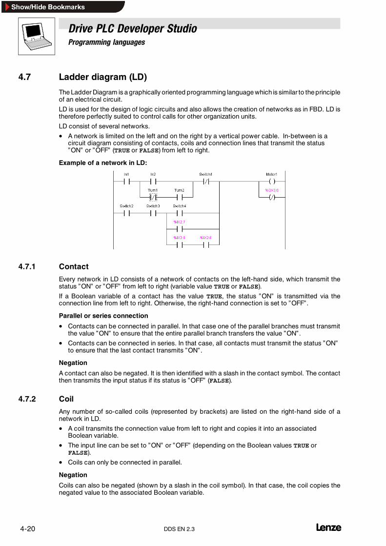
Drive PLC Developer StudioProgramming languages
4-20 lDDS EN 2.3
4.7 Ladder diagram (LD)
The Ladder Diagram is a graphically oriented programming language which is similar to theprincipleof an electrical circuit.
LD is used for the design of logic circuits and also allows the creation of networks as in FBD. LD istherefore perfectly suited to control calls for other organization units.
LD consist of several networks.
• A network is limited on the left and on the right by a vertical power cable. In-between is acircuit diagram consisting of contacts, coils and connection lines that transmit the status”ON” or ”OFF” (TRUE or FALSE) from left to right.
Example of a network in LD:
4.7.1 Contact
Every network in LD consists of a network of contacts on the left-hand side, which transmit thestatus ”ON” or ”OFF” from left to right (variable value TRUE or FALSE).
If a Boolean variable of a contact has the value TRUE, the status ”ON” is transmitted via theconnection line from left to right. Otherwise, the right-hand connection is set to ”OFF” .
Parallel or series connection
• Contacts can be connected in parallel. In that case one of the parallel branches must transmitthe value ”ON” to ensure that the entire parallel branch transfers the value ”ON” .
• Contacts can be connected in series. In that case, all contacts must transmit the status ”ON”to ensure that the last contact transmits ”ON” .
Negation
A contact can also be negated. It is then identified with a slash in the contact symbol. The contactthen transmits the input status if its status is ”OFF” (FALSE).
4.7.2 Coil
Any number of so-called coils (represented by brackets) are listed on the right-hand side of anetwork in LD.
• A coil transmits the connection value from left to right and copies it into an associatedBoolean variable.
• The input line can be set to ”ON” or ”OFF” (depending on the Boolean values TRUE orFALSE).
• Coils can only be connected in parallel.
Negation
Coils can also be negated (shown by a slash in the coil symbol). In that case, the coil copies thenegated value to the associated Boolean variable.

Drive PLC Developer StudioProgramming languages
4-21l DDS EN 2.3
4.7.3 Set/Reset coil
A coil can also be defined as set or reset coil.
• A variable of a set coil becomes TRUE if the network result is TRUE.
• A variable of a reset coil becomes FALSE if the network result is FALSE.
• If the conditions are not fulfilled, the variable does not change.
A set coil (”S” in the coil symbol)can assume ”ON” status, but can then no longer be reset to ”OFF” .
A Reset coil (”R” in the coil symbol) can assume ”OFF” status, but can then no longer be reset to”ON” .
4.7.4 Function blocks in LD
In addition to contacts and coils, LD allows the input of function blocks and programs.
In the network, function blocks and programs must have an input and output with Boolean valuesand can be used at the same locations as contacts, i.e. on the left-hand side of the LD network.
4.7.5 LD as FBD
Use global variables or direct calls if the result of a circuit in LD is to be used to control otherorganization units.
Global variable
The result of a circuit can be saved with the help of the coils in a global variable that is then furtherused otherwise.
Direct call
The call can be directly installed into your LD network. For this purpose, insert an EN organizationunit (”EN” stands for ”Enable”).
• EN organization units are normal operators, functions, programs or function blocks that havean additional input labelled EN. This input is a BOOL-type input.
• An EN organization unit will only be evaluated if its EN input is TRUE.
• An EN organization unit is switched in parallel to the coils, with the EN input being linked tothe connection line between the contacts and the coils. If the status ”ON” is transmitted viathis line, the organization unit will be evaluated normally.
• Based on such an EN organization unit, networks can be generated as in FBD.

Drive PLC Developer StudioProgramming languages
4-22 LDDS EN 2.3
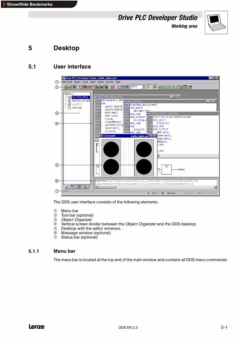
Drive PLC Developer StudioWorking area
5-1l DDS EN 2.3
5 Desktop
5.1 User interface
�
�
�
�
�
�
�
The DDS user interface consists of the following elements:
� Menu bar� Tool bar (optional)� Object Organizer� Vertical screen divider between the Object Organizer and the DDS desktop.� Desktop with the editor windows.� Message window (optional)� Status bar (optional)
5.1.1 Menu bar
The menu bar is located at the top end of the main window and contains all DDS menu commands.

Drive PLC Developer StudioWorking area
5-2 lDDS EN 2.3
5.1.2 Tool bar
The tool bar provides for quick access to frequently used menu commands.
• Click on an icon to execute the underlying command.
Tip!Positioning the mouse pointer briefly over a tool bar icon will display a tooltip with the icon name.
Use the FIND function in the Online Help to display more detailed information on the associated iconand its functionality.
• The selection of available functions is dependent on the active window.
• Tool bar display is optional.Project�Options category Desktop
5.1.2.1 Zoom
This zoom function in the tool bar allows zooming within all graphic editors and the visualization.Zoom is effective in the active window only.
The organization units of editors and visualization can be edited more efficiently.
5.1.3 Object Organizer
The Object Organizer is located at the left-hand sideof theDDS mainwindow and allows fast accessto the four object types:
• Organization units
• Data types
• Visualizations
• Resources
Click the associated tab in the Object Organizer to change between the object types, or use the leftor right arrow key.
Drive PLC Developer StudioWorking area
5-3l DDS EN 2.3
5.1.4 Vertical screen divider
The screen divider is the boundary between two non-overlapping windows.
The DDS offers screen dividers between
• the Object Organizer and the desktop of the main window
• the interface (declaration part) and the implementation (instruction part) of organization units
• the desktop and the message window.
Position the mouse pointer over the screen divider to move it. For this purpose, keep the left mousekey depressed and move the mouse.
Tip!Note that the screen divider will always remain at its absolute position even if the window size ischanged. Enlarge the window if the screen divider seems to have disappeared.
5.1.5 Desktop
The desktop is on the right-hand side of the DDS main window. All object editors and the LibraryManager are opened in this pane. The window title bar displays the associated object name.Organization units are identified with an abbreviated organization unit type and the appliedprogramming language.
Tip!Menu command Window in the main menu lists all window management commands.
5.1.6 Message window
The message window appears below the desktop in the main window, separated by a horizontalscreen divider.
It contains all messages from the last compile, check or compare. Search results and crossreferences can also be output here.
• Double-click a message in the message window or press <Enter> to open the editor with theassociated object. The relevant line of the object will be highlighted.Use the commands Edit����Next fault and Edit����Previous fault to jump from one errormessage to the next.
• The message window can be shown or hidden by pressing <Shift>+<ESC>.
Drive PLC Developer StudioWorking area
5-4 lDDS EN 2.3
5.1.7 Status bar
The status bar at the bottom of the DDS main window displays information about the current projectand menu commands.
• If a status applies, the associated expression appears in black at the right-hand end of thestatus bar, otherwise it is greyed out.
• Status bar display is optional.Project�Options category Desktop
Online mode
In online mode, the word Online is displayed in black; in offline mode, it is greyed out.
The status bar shows the following statuses in online mode.
• SIM: DDS is in simulation mode
• RUNNING: the program is being processed
• BP: a breakpoint is set
Other status bar displays
• Text editors display the line and column number of the current cursor position. The lettersOVR appear in the status bar in overtype mode.
• If the mouse pointer is in a visualization, the current X and Y position of the cursor will begiven in pixels relative to the top left-hand corner of the image.
• If the mouse pointer is positioned over an element, or if an element is being edited, thenumber of the element will be displayed.
• If an element has been selected for insertion, this element will also be displayed (e.g.rectangle).
• If a menu command has been selected but not confirmed, a short description will be given inthe status bar.
• The status bar displays the word READ if a project is opened with read access only.
5.1.8 Shortcut menu
Keyboard: <Umschalt>+<F10>
Use the right mouse key to display a shortcut menu.
• The shortcut menu contains the commands most frequently used for a selected object or theactive editor.
• The selection of available commands is dependent on the active window.

Drive PLC Developer StudioWorking area
5-5l DDS EN 2.3
5.2 Arrange windowsThe menu Window lists all window management commands.These are commands for automatic window arrangement, opening the Library Manager and the logand to change between active windows.The menu Window also lists all open windows at the bottom in the sequence they were activated.• Click an entry to change to the associated window. The active window is identified with a tick
(�) in front of the menu entry.
5.2.1 Commands in the “Window” menu
5.2.1.1 Tile horizontallyIcon: - Menu: Window�Tile horizontally Keyboard: -
Use this command to tile all windows on the desktop horizontally so that they will not overlap butfill the whole desktop.
5.2.1.2 Tile verticallyIcon: - Menu: Window�Tile vertically Keyboard: -
Use this command to tile all windows on the desktop vertically so that they will not overlap but fillthe whole desktop.
5.2.1.3 CascadeIcon: - Menu: Window�Cascade Keyboard: -
Use this command to cascade all windows on the desktop.
5.2.1.4 Arrange iconsIcon: - Menu: Window�Arrange icons Keyboard: -
Use this command to arrange all windows minimized on the desktop in a row at the bottom of thedesktop.
5.2.1.5 Close allIcon: - Menu: Window�Close all Keyboard: -
Use this command to close all windows open on the desktop.
5.2.1.6 MessagesIcon: - Menu: Window�Messages Keyboard: <Umschalt>+<Esc>
Use this command to open or close the message window displaying the messages from the lastcompile, check or compare.• If the message window is open, a tick (�) appears in front of the command in the menu.
5.2.1.7 Library ManagerIcon: - Menu: Window�Library Manager Keyboard: -
Use this command to open the dialog box Library Manager (� 8-41)
5.2.1.8 logIcon: - Menu: Window�log Keyboard: -
Use this command to open the log window. The menu command log is available for the open logwindow. (� 6-42)

Drive PLC Developer StudioWorking area
5-6 lDDS EN 2.3
5.3 Basic settings
5.3.1 DDS options
Use the menu command Project����Options in the main menu to configure the display of your mainwindow. There are other setting options for DDS customization.
Unless otherwise defined, the settings made here will be stored in the DDS ini file and restored onnext start.
5.3.1.1 OptionsIcon: - Menu: Project�Options... Keyboard: -
Use this command to open the dialog box Options.
The options are divided into several categories. Select the required category from the left-hand sideof the field Category with a mouse click, or use the arrow keys to do so, and set the required optionson the right-hand side.
Options�Load & save
If an option is active, a tick appears in front of the option. (�)
Creating a backup
If check box Create backup is activated, the DDS saves the old file to a backup file with theextension ” .bak” on each save to allow for the version before the last save to be restored.
Autosave
If check box Autosave is activated, your project, while being edited, will be constantly saved to atemporary file with an ” .asd” extension in accordance with the specified time interval (save interval).This file will be deleted when the program completes normally.
Should the DDS terminate ”abnormally” for some reason (mains failure, for example), the file will notbe deleted and the system will display a message on project re-launch to advise that a backup filehas been created. It is now up to the user to decide which file to open (original or backup file).
Autosave interval (min)
Enter a time interval in minutes for temporary backup.
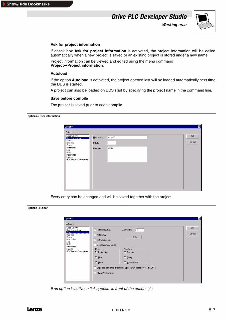
Drive PLC Developer StudioWorking area
5-7l DDS EN 2.3
Ask for project information
If check box Ask for project information is activated, the project information will be calledautomatically when a new project is saved or an existing project is stored under a new name.
Project information can be viewed and edited using the menu commandProject����Project information.
Autoload
If the option Autoload is activated, the project opened last will be loaded automatically next timethe DDS is started.
A project can also be loaded on DDS start by specifying the project name in the command line.
Save before compile
The project is saved prior to each compile.
Options�User information
Every entry can be changed and will be saved together with the project.
Options �Editor
If an option is active, a tick appears in front of the option. (�)

Drive PLC Developer StudioWorking area
5-8 lDDS EN 2.3
Auto declaration
If the option Auto declaration is activated, a dialog box will appear in all editors when entering avariable that has not been declared yet. This dialog box is called Variable declaration.
Autoformat
If the option Autoformat is activated, the DDS carries out automatic formatting in the instruction listeditor and the declaration editor.
After a line has been exited, the following will be formatted:
• Lowercase operators will be displayed in uppercase.
• Tabs will be inserted for uniform column arrangement.
Declarations as tables
If the option Declarations as tables is activated, variables can be edited as table instead of usingthe declaration editor.
• This table is arranged as a card index box with tab cards for input, output, local andinput/output variables.
• Fields for name, address, type, initial value and comment are available for each variable.
Tab width
Use the field Tab width to specify the tabulator width for the editors.
• The default setting is four characters, with the character width being dependent on theselected font.
Font
Click Font to open the dialog box Font and select the font for the editors.
• The font size is a basic unit for all drawing operations. A larger font size therefore does notonly result in a larger image but also a larger printout for each DDS editor.
Mark
Use the group box Mark to choose from three different marking formats for the graphic editors.
• Dotted line: The mark is a dotted rectangle.
• Line:The mark is a rectangle consisting of a continuous line.
• Filled: The mark is a filled rectangle (inverse).
A dot identifies the active selection.

Drive PLC Developer StudioWorking area
5-9l DDS EN 2.3
Bit values
Use the group box Bit values to choose between three different representation formats for binarydata (types BYTE, WORD, DWORD) for monitoring:
• Decimal• Hexadecimal• BinaryA dot identifies the active selection.
Monitoring of complex types
Show POU symbols
If chec box Show POU symbols is selected, Lenze organization unit signal propagation charts areshown as bitmaps.
Options �Desktop
If an option is active, a tick appears in front of the option. (�)
Tool bar
If the option Tool bar is activated, the tool bar will be displayed below themenu bar for faster accessto menu commands.
Status bar
If the option Status bar is activated, the status bar will be displayed at the bottom edge of the DDSmain window.
Online in security mode
If the option Online in security mode is activated, online mode displays a dialog box for thecommands Start, Stop, Reset, Breakpoint on, Single cycle and Write values offering anadditional security prompt as to whether the command is indeed to be executed. This option issaved together with the project.
Language
DDS dialog and menu languages are German and English.
Note!Languages can be selected under Windows NT and Windows 2000 only.

Drive PLC Developer StudioWorking area
5-10 lDDS EN 2.3
Printer borders
In every editor window, the printer borders are outlined by red dashed lines. The printer borders aredependent on printer properties and the size of the content area of the set templateFile����Documentation setup.
F4 ignores warnings
Pressing F4 after the compile will return the focus only to those lines with error messages in themessage window, ignoring the warning outputs.
Options �Colours
DDS colour settings can be changed for the following elements:
• Line numbers (light grey*)
• Breakpoint position (dark grey*)
• Set breakpoint (light blue*)
• Current position (red*)
• Reached position (green*)
• Monitoring of BOOL (blue*)
Click one of the buttons to open the dialog box Colours and select the required colour for theelement.
*DDS default

Drive PLC Developer StudioWorking area
5-11l DDS EN 2.3
Options�Directories
Project
The DDS is looking for libraries and configuration files in directories entered in a project. It is alsopossible to enter directories that are to be used to store compile files.
Click (...) behind an input field to open a dialog box for the selection of directories within yourdirectory structure (Browse). For library and configuration files, the system allows the input of severalpaths each, separated by a semicolon “ ;” . The information is saved together with the project.
Common
This is where those directories can be entered that the DDS will search for libraries and configurationfiles. It is also possible to enter directories that are to be used to store compile files.
Click (...) behind an input field to open a dialog box for the selection of directories within yourdirectory structure (Browse).For library and configuration files, the system allows the input of severalpaths each, separated by a semicolon “ ;” . The information will be written to the program system inifile and apply for all projects.
Automation system
This is where the directories for libraries and configuration files are shown that are set in theautomation system, through specification in the target file, for example. These windows cannot beedited. An entry can be selected and copied.
DDS searches follow a sequence of project, automation system and common. Where identicallynamed files exist, that in the previously searched directory will be applied.

Drive PLC Developer StudioWorking area
5-12 lDDS EN 2.3
Options�log
This dialog box allows configuration of a file that chronologically logs all user actions and internalprocesses in online mode as project log.
The system will open a suitable dialog box if an existing project is opened for which no log has asyet been created. This dialog advises that a log is being created. First input will be made during thenext log-in process.
The log is automatically stored as a binary file when the project is saved.Option Directory for project logs offers the option of saving the log in a different directory.
The log is automatically given the name of the project and an extension .log.Use Maximum project log size to define the maximum number of online sessions to be logged.If this number is exceeded during logging, the latest input will delete the earliest one.
The log function can be switched on and off in the check box Activate logging.
Use the group field Filter to select the actions to be logged.
• User action
• Internal action
• Status change
• Exception
Only the actions of the selected categories will be displayed in the log window or written to the log.(� 6-42)

Drive PLC Developer StudioWorking area
5-13l DDS EN 2.3
Options�Build
Debugging
If the option Debugging is activated, the code may become noticeably longer since additionaldebugging code is generated. This is necessary to use the DDS debugging functions. The optionis saved together with the project.• Only if check box Debugging is active can breakpoints be set and single stepping is
possible.• If the option Debugging is deactivated, the code will be shorter and execution faster.
Replace constants
This option loads the value directly for each constant. In online mode, constants are displayed ingreen. A constant can then no longer be forced, written or monitored. While the option isdeactivated, the value is loaded via variable access to a memory location. Although this allowswriting of the variable value, it also means a longer processing time.
Nested comments
This option allows the input of nested comments.(*a:=inst.out;(*to be checked*)b:=b+1;*)
The comment beginning with the first parenthesis is the outer one and completed with the lastparenthesis.
Create binary file of the application
Selection of this option means that a binary image of the generated code(boot project) will be created in the project directory during a compile. File name: projectname.bin.
Macro before compile
This option influences the compile process - the macro is run prior to the compile.
Macro after compile
This option influences the compile process - the macro is run after the compile.
Macro commands
The appendix includes a list of all macros.Command line commands (� 15-1)
Command file commands (� 15-2)

Drive PLC Developer StudioWorking area
5-14 lDDS EN 2.3
The following macro commands cannot be executed.
file new, file open, file close, file save as, file quit, online,project compile, project check, project build, debug, watchlist
For a more detailed description as to how to create macros referOptions�MacrosAll settings defined in the dialog box Build options are saved together with the project.
Options�Passwords
The DDS offers password protection for your files against unauthorized access, opening or editing.
Defining a password for opening a file:
1. Enter the required password in text field Password.Every letter is represented by an asterisk (*).
2. Repeat the password entry in the text field Confirm password.3. Click OK to close the dialog box.If the message ”Password and its acknowledgement do not match” appears, one of the two inputscontains a typing error. Retype both entries to ensure that the dialog box closes without any errormessages.
When the file is saved and re-opened, a dialog will be displayed for password entry.The project will only be opened if the password is correct, otherwise the message ”The passwordis not correct” will appear.
Defining a password for editing a file:
Passwords can protect a file from being opened and/or edited:1. Enter the required password in text field Write Protection Password.
Every letter is represented by an asterisk (*).2. Repeat the password entry in the text field Confirm write protection password.3. Click OK to close the dialog box.If the message ”Password and its acknowledgement do not match” appears, one of the two inputscontains a typing error. Retype both entries to ensure that the dialog box closes without any errormessages.Write protected projects can also be opened without the password.• To do so, click Cancel when the DDS prompts for the write protection password on opening
the file. It is now possible to compile the project, load it into the control, simulate it, etc., but itcannot be edited.
• The status bar now includes the display READ.

Drive PLC Developer StudioWorking area
5-15l DDS EN 2.3
Note!Make sure to remember the passwords. Contact Lenze if you do forget one of the passwords.
• The passwords are saved together with the project.
• Create user groups to assign more specific access rights.
Options�Symbol configuration
Select the category Symbol configuration to open the following dialog box.
The dialog box assists symbol file configuration (text file*.sym or binary file*.sdb)These are requiredfor data exchange with the control via the symbol interface and are used by Global DriveOscilloscope for this purpose, for example.
Dump symbol entries
If the check box is activated, every project compile automatically creates symbol entries for theproject variables in the file.
Configure symbol file
Use this button to open the dialog box Set object attribute.
Select the required project organization units from the tree structure, and tick the required checkbox.

Drive PLC Developer StudioWorking area
5-16 lDDS EN 2.3
Export variable of object
The variables of the selected object are output to the symbol file. The other options take effect onlyif this check box is ticked.
Export data entries
For structures and arrays of the object, entries are generated for access to the overall variables.
Export structure components
For object structures, a separate entry is generated for each variable component.
Export array entries
For object arrays, a separate entry is generated for each variable component.
Write access
The object variables may be modified via the OPC server.
Once the setting is effected for the current organization unit selection, another organization unit canbe selected and given different options.
OK
Using this button to close the dialog box means that all changes will be saved.
Options�Macros
Select the category Macros to open the following dialog box.
Name
Enter the name for the macro in this text box.
New
Press the button New to record the created macro.
Macro
This field lists all created macros. Highlighted macros can be deleted with the <Del> key.
Rename
Once an existing macro has been selected in the macro list, it can be renamed via dialog box Name.Press the button Rename to rename the macro.

Drive PLC Developer StudioWorking area
5-17l DDS EN 2.3
Commands
This dialog box defines or edits commands for the macro. A new command line is inserted bypressing <Ctrl>+<Enter>.The right mouse key displays the shortcut menu with standard editorfunctions. Components of a command that belong together can be concatenated with the help ofquotes.
Macro commands - commands
The appendix includes a list of all macros.
Command line commands (� 15-1)
Command file commands (� 15-2)
Menu
This dialog box defines the menu entry to insert the macro underEdit�Macros.Place an & in front of a letter to turn it into a shortcut. The name Ma&cro 1 generates menu entryMacro 1.
OK
Exits the dialog box and saves the input in the project.A macro check will be performed only at the time the menu command is executed.
Options�GDC Device Description
Use this dialog box to select whether a project-specific device description file (PDB) is to be createdfor Global Drive Control (GDC) and, if so, for which languages.
Tip!A PDB will be created only if a directory has been specified under Path and the check boxBuild GDC Device Description has been activated. The PDB is built/updated on project compileif PDB-relevant data have changed.
The file name of the PDB consists of the project name followed by an index (”_S” , ”_1” , ”_2”) for theassociated language and the extension ” .pdb” .
Example:
• Name of the project: ”Example”
• Language selection: Standard language and Language Two
• � PDB file names: ”Example_S.pdb” and ”Example_2.pdb”

Drive PLC Developer StudioWorking area
5-18 lDDS EN 2.3
Directory
Use the input field Path to determine the directory path for the device description files (PDBs) to becreated by the DDS for Global Drive Control.
• Click ... behind the input field to open a dialog box for the selection of directories within yourdirectory structure (Browse).
Language selection
Select the languages for which to create a PDB.
• Up to three country-specific PDBs can be created per project.
• The associated GDC display texts for the relevant code are defined in the Instance ParameterManager in the dialog box More details and information (call via Extended in the ParameterManager).
• The selected language is identified with a tick. (�)
Basic language
The pdb file will be generated in the selected language.
Build GDC Device Description
If check box Build GDC Device Description is activated, a PDB for GDC will be built/updated forevery language selected under Language selection in the directory specified under Path duringevery project compile.
• This project-specific PDB contains the basic codes for the associated PLC (based on itsbasic PDB) and the project-specific codes defined in the Parameter Manager.
• It is generated only if PDB-relevant data have changed.
• The device description is also saved into the project directory for easier handling of theGlobal Drive Loader software.
• If the Lenze OPC server is installed, the device description will also be copied into its PDBdirectory.

Drive PLC Developer StudioWorking with projects and objects
6-1l DDS EN 2.3
6 Working with projects and objects
6.1 Managing projects
Those DDS commands that refer to the entire project are available in the main menu under File andProject.
The menu Project also contains commands that refer to objects. A detailed description of thesecommands is included in the chapter ”Working with objects” .(� 6-24)
Note!Write protection on *.bin file
For each changed or translate project, the corresponding *.bin will be overwritten. This file is savedin the same directory as the project. If this file is write-protected, the project cannot be translated.You have to remove the write protection.
6.1.1 Commands in the “File” menu
6.1.1.1 NewIcon: Menu: File�New Keyboard: -
Use this command to a create a blank project called ”Untitled” . Change the name when saving theproject.
6.1.1.2 New, with templateIcon: - Menu: File�New, with template Keyboard: -
Use this command to create a blank project named ”Untitled” including an optional template.
The template has the extension *.lpc and contains a fixed Lenze configuration.
The Lenze configuration includes:
• Program POUOrganization units with technology function.
• Required libraries
• Global variables
• Entries in the PLC configuration
• Entries in the task configuration
• Predefined user codes
• Visualization and Receipt Manager (as required)
Open the dialog box Open and select a template file with the extension ”*.lpc” .
If the template is protected by Passwords or defined with User groups, the system will prompt fora password.

Drive PLC Developer StudioWorking with projects and objects
6-2 lDDS EN 2.3
6.1.1.3 OpenIcon: Menu: File�Open Keyboard: <Ctrl>+<O>
Use this command to open an existing project.
• If a project has been opened and changed before, the user will be prompted as to whether thisproject is to be saved or not.
Open the dialog box Open and select a project file with the extension ”*.pro” or a library file with theextension ”*.lib” . This file must exist already. The command Open does not allow the creation of anew project.
• The menu File lists the last-opened projects at the very bottom. Selecting one of thoseprojects will open it.
• If passwords or user groups have been defined for the project, the system will prompt for apassword.
6.1.1.4 CloseIcon: - Menu: File�Close Keyboard: -
Use this command to close the currently open project.
• If the project was changed, the user will be prompted as to whether these changes are to besaved or not.
• If the name of the project to be saved is ”Untitled” , enter a new name.
6.1.1.5 SaveIcon: Menu: File�Save Keyboard: <Ctrl>+<S>
Use this command to save the project if it was changed.
• If the name of the project to be saved is ”Untitled” , enter a new name.
6.1.1.6 Save asIcon: - Menu: File�Save as Keyboard: -
Use this command to save the current project under a new name or as library. The original projectfile remains unchanged.
Selection of the command opens the dialog box Save as.
• Select either an existing file name to overwrite an existing project or enter a new file name.
• Select the required file type.
Saving the project under a new name
If the project is to be saved under a new name only, select file type ”DDS Project (*.pro)” .
Then click OK.
• The current project will be saved to the selected file. If the new file name already exists, theuser will be prompted as to whether this file is to be overwritten or not.
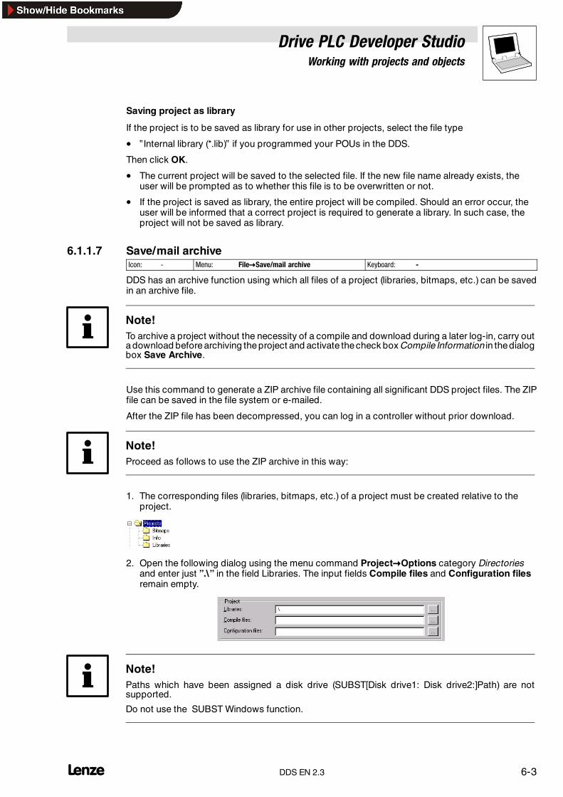
Drive PLC Developer StudioWorking with projects and objects
6-3l DDS EN 2.3
Saving project as library
If the project is to be saved as library for use in other projects, select the file type
• ” Internal library (*.lib)” if you programmed your POUs in the DDS.
Then click OK.
• The current project will be saved to the selected file. If the new file name already exists, theuser will be prompted as to whether this file is to be overwritten or not.
• If the project is saved as library, the entire project will be compiled. Should an error occur, theuser will be informed that a correct project is required to generate a library. In such case, theproject will not be saved as library.
6.1.1.7 Save/mail archiveIcon: - Menu: File�Save/mail archive Keyboard: -
DDS has an archive function using which all files of a project (libraries, bitmaps, etc.) can be savedin an archive file.
Note!To archive a project without the necessity of a compile and download during a later log-in, carry outa download before archiving the project and activate thecheck box Compile Information in thedialogbox Save Archive.
Use this command to generate a ZIP archive file containing all significant DDS project files. The ZIPfile can be saved in the file system or e-mailed.
After the ZIP file has been decompressed, you can log in a controller without prior download.
Note!Proceed as follows to use the ZIP archive in this way:
1. The corresponding files (libraries, bitmaps, etc.) of a project must be created relative to theproject.
2. Open the following dialog using the menu command Project�Options category Directoriesand enter just ”.\” in the field Libraries. The input fields Compile files and Configuration filesremain empty.
Note!Paths which have been assigned a disk drive (SUBST[Disk drive1: Disk drive2:]Path) are notsupported.
Do not use the SUBST Windows function.
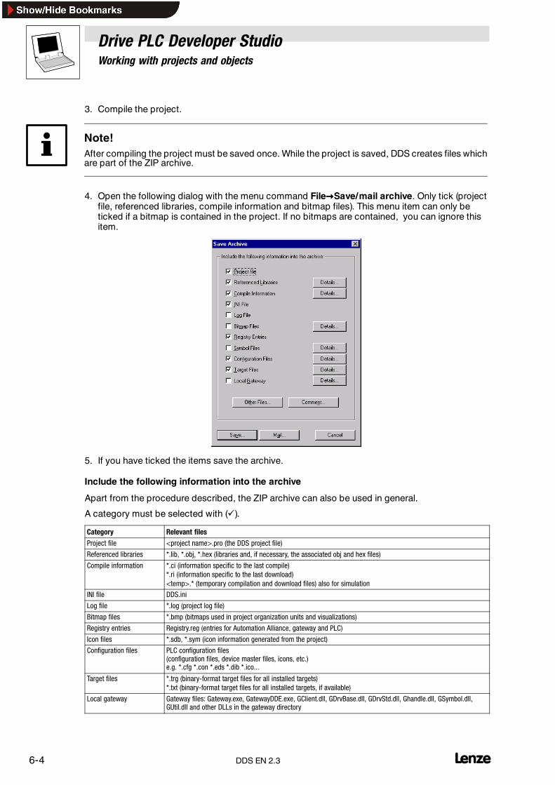
Drive PLC Developer StudioWorking with projects and objects
6-4 lDDS EN 2.3
3. Compile the project.
Note!After compiling the project must be saved once. While the project is saved, DDS creates files whichare part of the ZIP archive.
4. Open the following dialog with the menu command File�Save/mail archive. Only tick (projectfile, referenced libraries, compile information and bitmap files). This menu item can only beticked if a bitmap is contained in the project. If no bitmaps are contained, you can ignore thisitem.
5. If you have ticked the items save the archive.
Include the following information into the archive
Apart from the procedure described, the ZIP archive can also be used in general.
A category must be selected with (�).
Category Relevant files
Project file <project name>.pro (the DDS project file)
Referenced libraries *.lib, *.obj, *.hex (libraries and, if necessary, the associated obj and hex files)
Compile information *.ci (information specific to the last compile)*.ri (information specific to the last download)<temp>.* (temporary compilation and download files) also for simulation
INI file DDS.ini
Log file *.log (project log file)
Bitmap files *.bmp (bitmaps used in project organization units and visualizations)
Registry entries Registry.reg (entries for Automation Alliance, gateway and PLC)
Icon files *.sdb, *.sym (icon information generated from the project)
Configuration files PLC configuration files(configuration files, device master files, icons, etc.)e.g. *.cfg *.con *.eds *.dib *.ico...
Target files *.trg (binary-format target files for all installed targets)*.txt (binary-format target files for all installed targets, if available)
Local gateway Gateway files: Gateway.exe, GatewayDDE.exe, GClient.dll, GDrvBase.dll, GDrvStd.dll, Ghandle.dll, GSymbol.dll,GUtil.dll and other DLLs in the gateway directory

Drive PLC Developer StudioWorking with projects and objects
6-5l DDS EN 2.3
Details
Use the button Details to request a dialog box for the direct selection of information on the respectivecategory.
The dialog box Details is explained on the basis of Details: Local gateway.
The dialog box shows the local gateway details that can be selected directly with (�). Use the buttonSelect all to select everything. Select none removes the ticks. Confirm with OK.
Other files
Use the button Other files to open a dialog box to transfer user-defined files into the archive.
Comment
The button opens a text editor to generate a README.TXT file that contains the specified text whichis automatically extended by the generation date and the version number of the currently used DDSversion.
Generating the ZIP archive
The ZIP archive can be generated once all settings have been made and checked.
Save
A ZIP file is generated and saved and can be stored at the desired location with the help of theWindows dialog. The file default name is projectname.zip. Pressing the button Save starts archivegeneration where the process is logged in the message window along with a progress bar display.
A blank e-mail is generated with the project attached as a ZIP file. This function requires correct MAPI(Messaging Application Programming Interface) installation.
Cancel
The process is cancelled. No settings are saved.

Drive PLC Developer StudioWorking with projects and objects
6-6 lDDS EN 2.3
6.1.1.8 PrintIcon: - Menu: File�Print Keyboard: <Ctrl>+<P>
Use this command to print the contents of the active window.
Selection of the command opens the dialog box Print.
• Select the required option and click OK. The active window will be printed. Every editor can becolour-printed.
• Use the button Properties to open the dialog box Printer setup.
• The layout of your printout can be defined under File����Documentation setup.
• During the printout, the number of pages already printed will be displayed in a dialog box. Theprintout will be stopped after the next page if this dialog box is closed.
• To document your entire project, use the command Project����Document project.
• To generate a document template for your project to specify the comments for all variablesused within the project, open a global variable list and use the command Extras����Createdocument template. (� 8-3)
6.1.1.9 Documentation setupIcon: - Menu: File�Documentation setup Keyboard: -
Use this command to specify the layout of the pages to be printed.
File
Use text field File to enter the name of the file with the extension ” .dfr” to save the page layout to.
• By default, the template is saved in the file ”DEFAULT.DFR” .
• To change an existing layout, click Browse to find the required file in your directory structure.
Edit
Select Edit to display the page layout template. Arrange the placeholders for page numbers, date,names for files and organization units as well as on-page graphics and define the text zone to printthe documentation in.
Tip!Use the button Printer setup to open the dialog box Printer setup to effect documentation settings.

Drive PLC Developer StudioWorking with projects and objects
6-7l DDS EN 2.3
Use the command Insert����Placeholder to select one of the five placeholders to be inserted into thelayout by simply drawing a rectangle and move it to the desired position, if necessary.
Placeholders will be substituted as follows in the printout:
Command Placeholder Effect
Page {Page} The current number of pages is printed.
POU name {POUName} The name of the current organization unit.
File name {FileName} The name of the project.
Date {Date} Current date.
Content {Content} The contents of the organization unit.
Use Insert����Bitmap to insert a bitmap (e.g. a company logo)into the page. Select a bitmap and drawa rectangle in the layout with the mouse. Further visualization elements may be inserted as well.
New page for each object/New page for each subobject
Select whether a new page is to be started for each object and subobject.
Printer setup
Use the button Printer setup to open the dialog box Printer setup to specify printer, paper format,etc.
OK/Cancel
Click OK to accept the changes or Cancel if you do not want to save them.
If the template has been changed, the user will be prompted on closing the window as to whetherthe changes are to be saved or not.
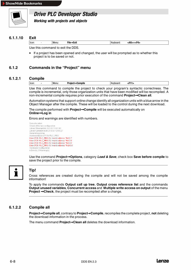
Drive PLC Developer StudioWorking with projects and objects
6-8 lDDS EN 2.3
6.1.1.10 ExitIcon: - Menu: File�Exit Keyboard: <Alt>+<F4>
Use this command to exit the DDS.
• If a project has been opened and changed, the user will be prompted as to whether thisproject is to be saved or not.
6.1.2 Commands in the “Project” menu
6.1.2.1 CompileIcon: - Menu: Project�Compile Keyboard: <F11>
Use this command to compile the project to check your program’s syntactic correctness. Thecompile is incremental, only those organization units that have been modified will be recompiled. Anon-incremental compile requires prior execution of the command Project����Clean all.
Automation systems that support online change identify all organization units with a blue arrow in theObject Manager after the compile. These will be loaded to the control during the next download.
The compile performed with Project����Compile will be executed automatically onOnline����Log in
Errors and warnings are identified with numbers.
Use the command Project����Options, category Load & Save, check box Save before compile tosave the project prior to the compile.
Tip!Cross references are created during the compile and will not be saved among the compileinformation!
To apply the commands Output call up tree, Output cross reference list and the commandsOutput unused variables, Concurrent access and Multiple write access on output of the menuProject ����Check, the project must be recompiled after a change.
6.1.2.2 Compile all
Project�Compile all, contrary to Project�Compile, recompiles the complete project, not deletingthe download information in the process.
The menu command Project�Clean all deletes the download information.

Drive PLC Developer StudioWorking with projects and objects
6-9l DDS EN 2.3
6.1.2.3 Clean all
Note!A log-in without another project download is possible only if the file *.ri containing the projectinformation of the last download was explicitly stored outside the project directory before and canbe reloaded prior to log-in.
Execute the menu command Project�Load download information.
Icon: - Menu: Project�Clean all Keyboard: -
This command clears the information of the last download and the last compile. Once the commandhas been executed, the system displays a dialog to advise that no log-in is possible without anotherdownload. You can continue or cancel the process at this point.
6.1.2.4 Load download informationIcon: - Menu: Project�Load download information... Keyboard: -
Use this command to directly reload the associated download information as long as the informationwas not stored in the project directory. The standard dialogFile����Open allows the direct loading of stored information.
• On each download, the download information is automatically put into a fileproject name Targetidentifier.ri. Example: LD_FillingPlants00000000r.riand included in the project directory.
• It will be reloaded automatically every time the project is opened and allows the control toperform an ID check to establish whetherthe project on the control matches the open project.
• A check is made to find those organization units whose generated code has changed. Onlythese organization units are reloaded during downloads for systems supporting online change.
If the *.ri file was deleted from the project directory via the menu command Project����Clean all, thedownload information can be explicitly loaded from another directory with Project����Loaddownload information....
6.1.2.5 Translate into other languagesIcon: - Menu: Project�Translate into other languages Keyboard: -
This menu item translates the current project file into a different national language by reading atranslation file generated from the project. The translation file will then be updated with translatedtexts in the desired national language with the help of a text editor.
For this purpose, the menu offers two subitems.
• Project����Translate into other languages����Create translation file
• Project����Translate into other languages����Translate project into another language

Drive PLC Developer StudioWorking with projects and objects
6-10 lDDS EN 2.3
Creating a translation file
• Enter a path in the field Translation file to store the file at the desired location. The standardfile extension is *.tlt (text file).
• To edit an existing translation file, select and open it with the Windows dialog Search.
• Optionally, the following information can be included with the generated or modifiedtranslation file:– Name, titles in the Object Organizer– Identifiers– Strings, comments, visualization– Position information
If the relevant options are ticked (�), the information will be included as linguistic symbols from thecurrent project into a translation file that either already exists or needs to be created, or updated inan existing one. If the relevant option is not selected, all information of the individual category, nomatter from which project, will be removed from the translation file.
The visualization texts in this case are the elements Text and Tool tip text of the visualizationelements.
Tip!Note for the visualization texts Text and Tool tip text of the visualization elements that they must beframed by two # characters in the configuration dialog of the visualization element #text# to beincluded in the translation file. (� 9-1)
Position information
This uses the data of file path, organization unit and line to describe the position of the linguisticsymbol provided for translation.
Three options are available:
• None No position formatting is generated.
• First occurrence The position at which the element to be translated first occurs, will beincluded in the translation file.
• All All positions at which the relevant element occurs in the project are specified.
Where an older translation file is edited that already contains more position information than selectedhere, this information will be reduced accordingly or deleted in full, independent of the project inwhich it was generated.

Drive PLC Developer StudioWorking with projects and objects
6-11l DDS EN 2.3
Tip!A maximum of 64 position information items will be generated for each element (linguistic symbol),even if the dialog box Create translation file, combination box Position information, specifies All.
Overwrite existing
All existing position information in the translation file being edited is overwritten, independent of theproject in which it was generated.This list contains identifiers for all languages in the translation file and that are to be included onexiting the dialog Create translation file.
Exclude
The button Exclude opens the dialog box Exclude libraries.
Here those project libraries can be selected whose user information is not to be accepted into thetranslation file.Use the buttons Add and Remove to determine which libraries to exclude and which to include.Confirm with OK. The dialog box closes.
Target languages
The button Add in the group box Target languages opens the dialog box Add target languages.
This is where you can add other languages. Enter English(USA), for example, and confirm with OK.The entered language must not have any white spaces or umlauts at the beginning and the end. Thebutton OK will be greyed out if the input is not acceptable or incomplete.
The button Remove in the group box Target languages deletes a language from the list, removingonly the selected language.
Creating a translation file
Press OK in the dialog box Create translation file to generate a translation file. The system will firstcheck whether there already exists another translation file with the same name.
Select No to return to the dialog box Create translation file.Select Yes to generate a copy of the existing translation file with the file nameBackup_of_translation file.tlt.
A translation file is generated as follows:• A placeholder ##TODO is generated for each new target language for each linguistic symbol
to be output.
• If an already existing translation file is being processed, any data entries of languages listed inthe translation file, but not in the target language list, will be removed, independent of theproject in which they were generated.
Editing a translation file
Open and save the translation file as a text file. Characters ## identify keywords. The ##TODOplaceholders in the file may be substituted with the applicable translated texts. A section delimitedby ##NAME_ITEM and ##END_NAME_ITEM is created for each linguistic symbol (comments:##COMMENT_ITEM etc.).

Drive PLC Developer StudioWorking with projects and objects
6-12 lDDS EN 2.3
Find below a sample section in the translation file for the name of the organization unit ST_Visu.Target languages are English(USA) and French. The position information for the project element tobe translated was also included in this example.
Prior to the translation
##NAME_ITEM[D:\DDS\projects\Bspdt_22.pro::ST_Visualisierung::0]ST_Visualisierung##English :: ##TODO##French :: ##TODO##END_NAME_ITEM
After the translation
##TODO was substituted with the English and French expressions.
##NAME_ITEM[D:\DDS\projects\Bspdt_22.pro::ST_Visualisierung::0]ST_Visualisierung##English :: ST_Visualization##French :: ST_Visu##END_NAME_ITEM
Make sure that translated identifiers and names remain valid under the standard and that strings andcomments are placed within the relevant brackets.
Note!The following blocks of the translation file should not be modified without detailed knowledge.
Language block, flag block, position information, original texts
6.1.2.6 Translate this projectIcon: - Menu: Project�Translate this project Keyboard: -
This menu command offers subitems
• Create translation file
• Translate project into another language
Tip!The translate cannot be undone. Save a project copy under a different name before translating.
Creating a translation file
Translating a project into another language
The current project can be translated into a different language, using a valid translation file.

Drive PLC Developer StudioWorking with projects and objects
6-13l DDS EN 2.3
Translation file
Specify the translation file path in this text field.
Search
This button takes you to the Windows file selection dialog.
Target language
This combination box offers the language identifiers to select the target language.
OK
The button starts the translate of the current project with the help of the specified translation file intothe selected target language. Progress and any error messages will be displayed during the translate.After the translate, the dialog box and all other open dialog windows will be closed.
Cancel
The button closes the dialog box without saving changes.
Should there be incorrect entries in the translation file, pressing OK will output an error message withfile path and incorrect line.[C:\Program files\DDS\projects\visu.tlt(78)]; expect translated text.
6.1.2.7 Document projectIcon: - Menu: Project�Document project... Keyboard: -
Use this command to print the documentation for an entire project.
Complete documentation comprises:
• Contents of the documentation
• Organization units
• Data types
• Call trees of organization units and data types
• Visualizations
• Resources (global variables, variable configuration, PLC configuration, task configuration,Watch and Receipt Manager)
• Cross reference list
• Table listing the codes assigned via the Parameter Manager
Documentation of ”Call up trees” and ”Cross reference list” requires an error-free projectcompile.

Drive PLC Developer StudioWorking with projects and objects
6-14 lDDS EN 2.3
Command selection opens a dialog box to select the objects to be printed:
• Make your selection and click OK.
• The dialog box Print is opened.
• The layout of the pages to be printed can be defined under File����Documentation setup.
6.1.2.8 ExportIcon: - Menu: Project�Export... Keyboard: -
The DDS offers the option of exporting and importing projects so that programs can be exchangedbetween different IEC programming systems.
• There is so far one standardized exchange format for organization units in IL, ST and SFC (IEC61131-3 Common Elements Format).
• The DDS offers a separate save format for organization units in LD and FBD and the otherobjects as IEC 61131-3 does not provide any appropriate textual format. The selected objectsare written to an ASCII file.
• Organization units, data types, visualizations and resources can be exported.
• In addition to that the entries in the Library Manager, i. e., the library linking information, canalso be exported. The libraries themselves are not exported.
Command selection opens a dialog box to select the objects to be exported.
• Make your selection and click OK.
• The dialog box Save is opened. Enter a file name with the extension ” .exp” .

Drive PLC Developer StudioWorking with projects and objects
6-15l DDS EN 2.3
6.1.2.9 ImportIcon: - Menu: Project�Import... Keyboard: -
Select the required export file from the dialog box.
The data are imported into the current project. If an identically-named object already exists in theproject, the dialog box ”Do you want to replace?” appears.
• Confirm with Yes to replace the object in the project with the object from the import file.
• Confirm with No to import the object from the import file with a name extension (underscoreand consecutive number ”_0” , ”_1” , ...).
• Confirm with Yes, all or No, none to apply the actions described before to all objects.
The message window logs the import.
Note!The following resource elements will be exported incompletely or not at all.
• Code initialization values
• Instance Parameter Manager
• Type Parameter Manager
• Task configuration
6.1.2.10 CompareIcon: - Menu: Project�Compare... Keyboard: -
Use this command to compare– two projects– an open project with the one last saved. Do not save to allow the changes to be displayed.
Tip!If the compare mode is active (status bar: Compare), the project cannot be edited.
Conventions
Designation Meaning
Current project The project currently edited
Project to compare The project called for the compare
Compare mode If Project�Compare was selected, the project is in compare mode
Unit The smallest compare unit
In compare mode, the current and the compare objects will be displayed in a split window. The editororganization units offer the possibility of a directly-aligned content compare. Filters can be activatedprior to the compare.
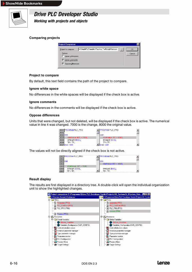
Drive PLC Developer StudioWorking with projects and objects
6-16 lDDS EN 2.3
Comparing projects
Project to compare
By default, this text field contains the path of the project to compare.
Ignore white space
No differences in the white spaces will be displayed if the check box is active.
Ignore comments
No differences in the comments will be displayed if the check box is active.
Oppose differences
Units that were changed, but not deleted, will be displayed if the check box is active. The numericalvalue in line 4 was changed. 7000 is the change, 8000 the original value.
The values will not be directly aligned if the check box is not active.
Result display
The results are first displayed in a directory tree. A double-click will open the individual organizationunit to show the highlighted changes.

Drive PLC Developer StudioWorking with projects and objects
6-17l DDS EN 2.3
Colours
Any differences are marked by coloured text.
RedUnit was modified and is displayed in red in both window panes.
BlueUnit exists only in the project to compare. The current project contains a space.
GreenUnit exists only in the current project. A space is inserted in the project to compare.
BlackNo differences in unit.
The following text can appear after the organization units of the current project:
• (Properties modified)This text appears after a name of an organization unit if the properties of the organizations unitdiffer.
• (Access authorizations modified)This text appears after an organization unit if the access authorizations differ.
6.1.2.11 CopyIcon: - Menu: Project�Copy Keyboard: -
Use this command to copy objects (organization units, data types, visualizations and resources)andlinks to libraries from other projects into the current project.
Selection of the command opens the dialog box Copy project.
1. Find the project from which you want to copy objects to the current project.
2. Click Open to open the project.
This will open a dialog box for object selection.
• If there already exists an object with the same name within the project, the name of the newobject will be entered with an underscore and a number (”_1” , ”_2” , ...) as the last characters.

Drive PLC Developer StudioWorking with projects and objects
6-18 lDDS EN 2.3
6.1.2.12 Project informationIcon: - Menu: Project�Project information Keyboard: -
Use this command to save information about the project.
Statistics
Click the button Statistics for statistical information about your project.
The statistics contain project information, number of POUs, data types, local and global variables assaved on the last compile.
• Select the dialog box Option, category Load & Save and there Ask for project information toobtain project information automatically when a new project is stored or an already existingproject is saved under a new name.
6.1.2.13 Global searchIcon: Menu: Project�Global search Keyboard: -
Use this command to find text in organization units, data types or objects of the global variables.
Command selection opens a dialog box to select the required objects.
Confirm the selection with OK to open the dialog box Find.
• If a text is found in an object, the object will be loaded into the associated editor and itsoccurrence displayed.
• Display of the found text, Find and Find next are analogous to the menu command Edit����Find.

Drive PLC Developer StudioWorking with projects and objects
6-19l DDS EN 2.3
Find what
Enter the required character sequence. If a text is found in an object, the object will be loaded intothe associated editor or Library Manager and its occurrence displayed.
Message window
Pressing this button lists all occurrences of the character sequence in question within the selectedobjects line-by-line in the message window and displays an occurrence total.
The following information is displayed.
• Object name
• Occurrence in the declaration part or implementation part of an organization unit
• Line or network number
• Complete line for text editors
• Complete text unit for graphic editors
The message window can display the following information for a requested character sequence”bottom” .
Global searchST-EXAMPLE (PRG-ST)(declaration) #5 bottom: INT:= -250;ST-EXAMPLE (PRG-ST)(implementation) #14 bottom :=yVal + offset;ST-EXAMPLE (PRG-ST)(implementation) #19 IF (bottom >-250) THENST-EXAMPLE (PRG-ST)(implementation) #20 bottom := Bottom -offset;The character sequence ’bottom’ was found 4 times.
A double-click on one of the lines opens the associated editor and highlights the line with thecharacter sequence. Function keys <F4> and <Shift>+<F4> allow toggling between the output lines.
Note!Not implemented for Parameter Manager and code initialization.
6.1.2.14 Global replaceIcon: - Menu: Project�Global replace Keyboard: -
Use this command to find text in organization units, data types or objects of global variables andreplace it with another text.
The libraries are not available for selection, and no output is possible into the message window.
Command selection opens a dialog box to select the required objects.
Confirm the selection with OK to open the dialog box Global replace.
Find next
• The occurrence is displayed if the text in the combination box Find what is found in one of theobjects to be searched.
Replace
• The current occurrence of the text in the combination box Find what found in the objects tobe searched is replaced with the text in the combination box Replace with.
• The highlight will jump to the next occurrence after the replace.
Replace all
• All occurrences of the text in the combination box Find what found in the objects to besearched are replaced with the text in the combination box Replace with.

Drive PLC Developer StudioWorking with projects and objects
6-20 lDDS EN 2.3
Cancel
• Closes the ”Find and replace” function.
Note!Not implemented for Parameter Manager and code initialization.
6.1.2.15 Project checkIcon: - Menu: Project�Check Keyboard: -
This menu command offers four separate subitems:
• Unused variables
• Overlapping memory areas
• Concurrent access
• Multiple save on output
The results are output in the message window.
Each of these four functions checks the status of the last compile. In other words, a project must havebeen compiled correctly at least once. The menu items will not be active if that is not the case.
Unused variables
This function looks for declared variables that are not used in the program. They are output withorganization unit name and organization unit line.Example: PLC_PRG (4) - var1Variables in libraries will not be considered.
Overlapping memory areas
This function checks overlapping of specific memory areas during variable assignment with the helpof the AT declaration.
Example:Assignment of variables
var1 AT %QB21: INTvar2 AT %QD5: DWORD
causes an overlap as they occupy byte 21 at the same time. Output is then as follows:
%QB21 is referenced by the following variables:
PLC_PRG (3): var1 AT %QB21PLC_PRG (7): var2 AT %QD5
Concurring access
This function looks for memory areas that are referenced in more than one task. No differencebetween read and write access. Output is then as follows:
%MB28 is referenced in the following tasks:
Task1 - PLC_PRG (6): %MB28 [read-only access]Task2 - POU1.ACTION (1) %MB28 [write access]

Drive PLC Developer StudioWorking with projects and objects
6-21l DDS EN 2.3
Multiple save on output
This function looks for memory areas that are accessed at several locations within a project. Outputis then as follows:%QB24 is described at the following locations:
PLC_PRG (3): %QB24PLC_PRG.POU1 (8): %QB24
6.1.3 User groupsThe DDS allows up to eight groups to be set up with different access rights to organization units, datatypes, visualizations and resources.Access rights can be defined for individual or all objects.• All projects are opened by a member of a specific user group.• The member must authenticate himself with a password.The user groups are numbered from 0 to 7, with group 0 having administrator rights, i. e., only group0 members must define passwords and access rights for all groups or objects.• New projects are initially not password-protected.• As long as no password has been set up for user group 0, everybody who opens the project is
a member of user group 0.• If a password has been set up within a project for user group 0, all groups are prompted for a
password when opening the project.1. Use the combination box User group to select the group you belong to.2. Use the text field Password to enter the password.3. Click OK to accept the input.If the password does not match the saved password, the message “The password is not correct.”will be displayed.• Only correct password entry will open the project.
Caution!A project may be opened via a user group that was not assigned a password.
• Use the menu item Project�User group passwords to assign passwords.
• Use the menu item Project�Objects�Access rights to assign rights for individual or allobjects.
6.1.3.1 User group passwordsIcon: - Menu: Project�User group passwords Keyboard: -
Use this command to open the dialog box User group passwords.
Note!This command can only be executed by members of group 0 (administrators).
Dialog box ”User group passwords”

Drive PLC Developer StudioWorking with projects and objects
6-22 lDDS EN 2.3
1. Use the combination box User group to select the group to assign a password to.
2. Use the text field Password to enter the password. Every letter is represented by an asterisk(*).
3. Repeat the entry in text field Confirm password.
4. Click OK to accept the input.
If the message “Password and its acknowledgement do not match.” appears, one of the two inputscontains a typing error.
• Retype both entries to ensure that the dialog box closes without any error messages.
If necessary, assign a password for the next group only then by requesting the command again.
Tip!Use the command Object����Access rights to assign rights for individual or all objects.
6.1.3.2 Exception handlingIcon: - Menu: Project�Exception handling Keyboard: -
Use this command to open the dialog box Exception handling where the watchdog time for thecyclical task and the general response of the selected automation system during a task overflow canbe defined. (� 8-31)
The layout of the dialog box Exception handling depends on the settings of the automation system.(� 8-38)
Servo PLC
Automation system with drive function
Note!The configuration of the digital outputs
– gets lost with the extension modules.– remains unchanged with the Servo PLC.

Drive PLC Developer StudioWorking with projects and objects
6-23l DDS EN 2.3
QSP Trip/CINH Warning
Event duringprogram processing Response of the automation system
PLC stop, breakpoint • Fail QSP is activated• Code C168, subcode 1
Error entry: none
• CINH is activated• Code C168, subcode 1
Error entry: none
• Motor continues running• Code C168, subcode 1
Error entry: none
Task overflow • Fail QSP is activated• Code C168, subcode 1
Error entry: Task overflow
• CINH is activated• Code C168, subcode 1
Error entry: Task overflow
• Motor continues running• Code C168, subcode 1
Error entry: none
Drive PLC
Automation system without drive function
Note!The configuration of the digital outputs
– remains unchanged with the extension modules.– remains unchanged with the Drive PLC.
QSP Trip/CINH Warning
Event duringprogram processing Response of the automation system
PLC stop, breakpoint • CINH is activated• Code C168, subcode 1
Error entry: none
• Motor continues running• Code C168, subcode 1
Error entry: none
Task overflow • CINH is activated• Code C168, subcode 1
Error entry: Task overflow
• Motor continues running• Code C168, subcode 1
Error entry: none
Drive PLC Developer StudioWorking with projects and objects
6-24 lDDS EN 2.3
6.2 Working with objects
This chapter describes how to work with objects and the help functions available to keep anoverview of a project (folders, call tree, cross reference list, etc.).
6.2.1 Object
”Objects” are organization units, data types, visualizations and resources, global variables, PLCconfiguration, task configuration and Watch and Receipt manager etc.
• Some of the folders inserted for project structuring are included in the project.An example of these is the organization unit folder with the action PLC_PRG.
• All objects of a project are saved in the Object Organizer.
Tip!Positioning the mouse pointer briefly over an organization unit in the Object Organizer will displaya tool tip with the type of the organization unit (program, function or function block).
Objects and folders can be moved within their object type with Drag & Drop. Use this Windowsfunction to select objects and to move them while keeping the left mouse key depressed. Shouldthe move result in a name collision, an error message is displayed and the process ignored.However, it is possible to generate an identically named subfolder within a folder.
6.2.1.1 Selecting objects
Selected objects are highlighted in blue.
Selecting the entire project
To select the entire project, select the project name in the first line.
Selecting individual objects
To select individual objects, click the associated object or move the dotted rectangleover theobjectwith the help of the arrow keys.
Objects with a plus sign in front of their icon are organization objects that contain further objects.
Click a plus sign to open the organization object, and click the minus sign to close it again.
Selection of an organization object also selects all associated objects.
Selecting an object range
Keep the <Umschalt> key depressed to select a range of objects.
Selecting several individual objects
Keep the <Ctrl> key depressed to select several individual objects.
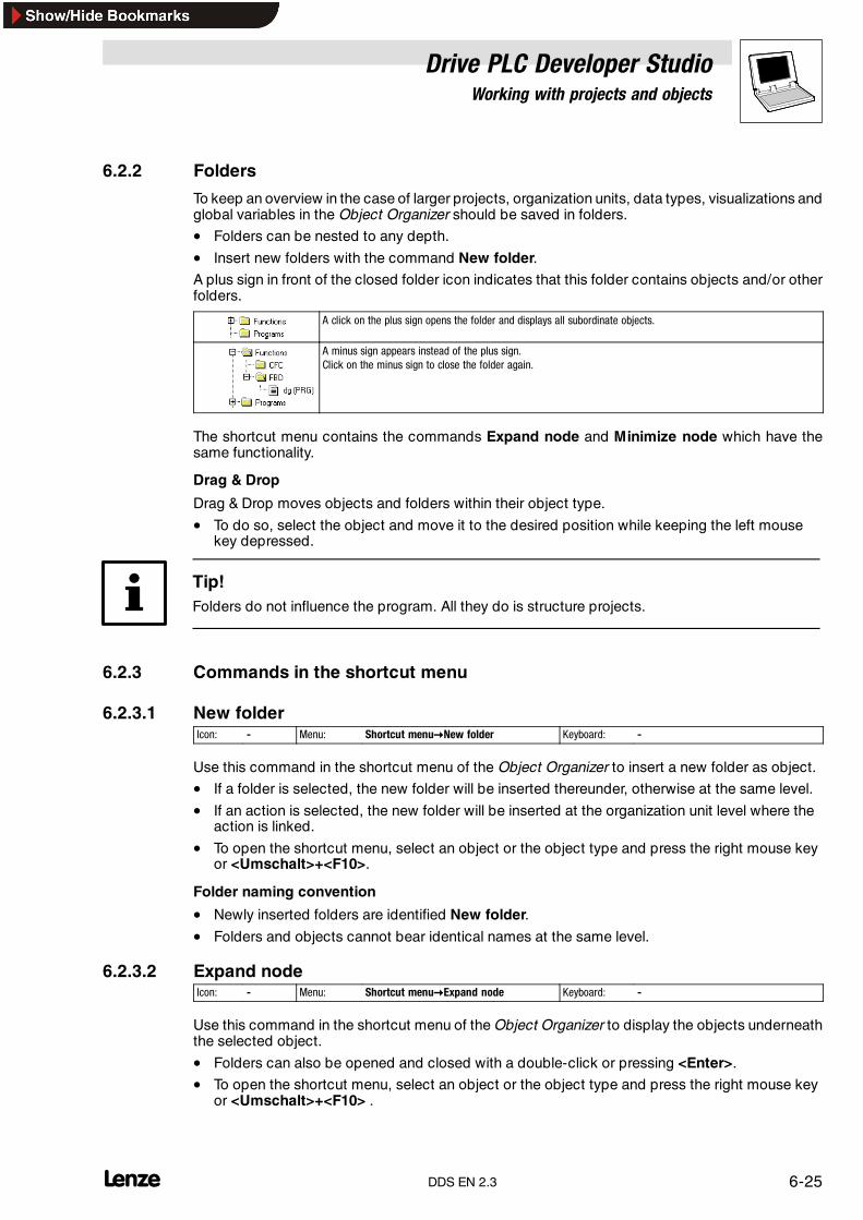
Drive PLC Developer StudioWorking with projects and objects
6-25l DDS EN 2.3
6.2.2 Folders
To keep an overview in the case of larger projects, organization units, data types, visualizations andglobal variables in the Object Organizer should be saved in folders.
• Folders can be nested to any depth.
• Insert new folders with the command New folder.A plus sign in front of the closed folder icon indicates that this folder contains objects and/or otherfolders.
A click on the plus sign opens the folder and displays all subordinate objects.
A minus sign appears instead of the plus sign.Click on the minus sign to close the folder again.
The shortcut menu contains the commands Expand node and Minimize node which have thesame functionality.
Drag & Drop
Drag & Drop moves objects and folders within their object type.
• To do so, select the object and move it to the desired position while keeping the left mousekey depressed.
Tip!Folders do not influence the program. All they do is structure projects.
6.2.3 Commands in the shortcut menu
6.2.3.1 New folderIcon: - Menu: Shortcut menu�New folder Keyboard: -
Use this command in the shortcut menu of the Object Organizer to insert a new folder as object.
• If a folder is selected, the new folder will be inserted thereunder, otherwise at the same level.
• If an action is selected, the new folder will be inserted at the organization unit level where theaction is linked.
• To open the shortcut menu, select an object or the object type and press the right mouse keyor <Umschalt>+<F10>.
Folder naming convention
• Newly inserted folders are identified New folder.
• Folders and objects cannot bear identical names at the same level.
6.2.3.2 Expand nodeIcon: - Menu: Shortcut menu�Expand node Keyboard: -
Use this command in the shortcut menu of the Object Organizer to display the objects underneaththe selected object.
• Folders can also be opened and closed with a double-click or pressing <Enter>.
• To open the shortcut menu, select an object or the object type and press the right mouse keyor <Umschalt>+<F10> .

Drive PLC Developer StudioWorking with projects and objects
6-26 lDDS EN 2.3
6.2.3.3 Minimize nodeIcon: - Menu: Shortcut menu�Minimize node Keyboard: -
Use this command in the shortcut menu of the Object Organizer to hide the objects listedunderneath the selected object.
• Folders can also be opened and closed with a double-click or pressing <Enter>.
• To open the shortcut menu, select an object or the object type and press the right mouse keyor <Umschalt>+<F10>.
6.2.4 Commands in the “Project” menu
6.2.4.1 Delete objectIcon: - Menu: Project�Delete object Keyboard: <Del>
Use this command to delete the currently selected object or folder with its objects from the ObjectOrganizer and thus the project.
• The user will be asked to confirm the delete.
• If the editor window of the object was open, it will be closed automatically.
• If the menu command Edit����Cut is used to delete an object, the object will be saved to theclipboard.
6.2.4.2 Insert objectIcon: - Menu: Project�Insert object Keyboard: <Insert>
Use this command to create a new object. The object type will depend on the tab selected in theObject Organizer.
Enter the name of the new object in the dialog box.
Note the following restrictions
• The organization unit names must not contain white spaces.
• Organization units and data types must not bear identical names.
• Global variable lists must not bear identical names.
• Actions within the same organization unit must not bear identical names.
• Visualizations must not bear identical names.
In all other cases, identical names are permitted. The actions of various different organization unitscan have identical names. Visualizations can have the same name as organization units.
Dialog for the creation of a new organization unit
The dialog must be fully completed. If the input is not in breach of the specified naming convention,press OK to create the new object in the Object Organizer and to display the associated inputwindow.
The menu command Edit�Insert inserts the object from the clipboard. No dialog is displayed in thiscase. If the name is inbreach of the naming convention, it will beextended witha continuous numberlade_1, lade_2...
• Make sure that the object name is not already in use.
• If the object is an organization unit, the organization unit type (program, function or functionblock) and the language to be used for programming must also be selected.
Confirming the input will display the associated input window.
Drive PLC Developer StudioWorking with projects and objects
6-27l DDS EN 2.3
6.2.4.3 Rename objectIcon: - Menu: Project�Rename object Keyboard: <Space bar>
Use this command to rename the currently selected object or folder.
• Make sure that the object name has not been used before.
• If the object edit window is open, the rename will automatically change its title.
6.2.4.4 Convert objectIcon: - Menu: Project�Convert object Keyboard: -
This command can only be used for organization units. Use this command to convert organizationunits written in CFC, ST, FBD, LD and IL into IL, FBD or LD.
Note!This command can only be used for organization units and requires a project compile for itsexecution.
1. Enter the name of the new organization unit in the dialog box. Make sure that the name of theorganization unit is not used for another organization unit.
2. Select the language into which to convert.
3. Click OK to add the new organization unit to your organization unit list.
6.2.4.5 Copy objectIcon: - Menu: Project�Copy object Keyboard: -
Use this command to copy a selected object and save it under a new name.
Enter the name of the new object in the dialog box. Make sure that the object name has not beenused before.
Click OK to copy the selected object.
• Use menu command Edit����Copy to copy the object to the clipboard. No dialog box isdisplayed in this case.
6.2.4.6 Edit objectIcon: - Menu: Project�Edit object Keyboard: <Enter>
Use this command to load an object selected in the Object Organizer into the associated editor.
If a window with this object is already open, it will be brought to the front for editing.
Also open an object for editing by
• double-clicking the associated object or
• by clicking the Object Organizer and inserting the first letter of the object name into theObject Organizer.

Drive PLC Developer StudioWorking with projects and objects
6-28 lDDS EN 2.3
Entering the first letter of the object name in the Object Organizer will open a dialog box displayingall objects of the set object type and starting with this letter.
• Select the required object and click Open to load the object to its editing window.
• The object type Resources supports this option for global variables only.
• This function is especially helpful for projects comprising a multitude of objects.
6.2.4.7 Access rightsIcon: - Menu: Project�Object access rights Keyboard: -
Use this command to open the dialog box to assign access rights to the different user groups.
Members of user group 0 (administrators) can now assign access rights individually to each usergroup.
The following settings are possible:
• No access: No member of the user group can open this object.
• Read access: A member of the user group can open this object in read-only mode.
• Full access: A member of the user group can open and modify this object.
The settings refer either to the object currently selected in the Object Organizer or, if the check boxApply to all is activated, to all organization units, data types, visualizations and resources of theproject.
As long as a password was set for user group 0, assignment to a user group happens through apassword prompt when opening a project.
6.2.4.8 PropertiesIcon: - Menu: Project�Object properties Keyboard: -
This command is available only if a global variable list has been selected in the Object Organizer.On generating a new global variable list, this dialog is opened with the menu commandObject�Insert.The folder Global variables must be selected in the Object Organizer.

Drive PLC Developer StudioWorking with projects and objects
6-29l DDS EN 2.3
6.2.4.9 Open instanceIcon: - Menu: Project�Open instance Keyboard: -
Use this command to open and display instances of function blocks in online mode. Double-clickingthe function block in the Object Organizer opens a selection dialog listing the instances of thefunction block and the implementation. Select the required instance or implementation and clickOK to display the list.
Note!Before this command can be executed, first select the function block whose instance is to beopened in the Object Organizer!
Then use the Help Manager to select the required instance of this function block.
Tip!Instances can be opened after log-in only! (Project has been compiled correctly and transferred tothe control with Online����Log in).
6.2.4.10 Output call treeIcon: - Menu: Project�Output call up tree Keyboard: -
Use this command to open a window to display the call tree of the object selected in theObject Organizer.
Example: Call tree for object PLC_PRG of the traffic light system.
The command requires the project to be compiled. See Project����Compile all. (� 6-8)
• The call tree contains calls of organization units and references to applied data types.
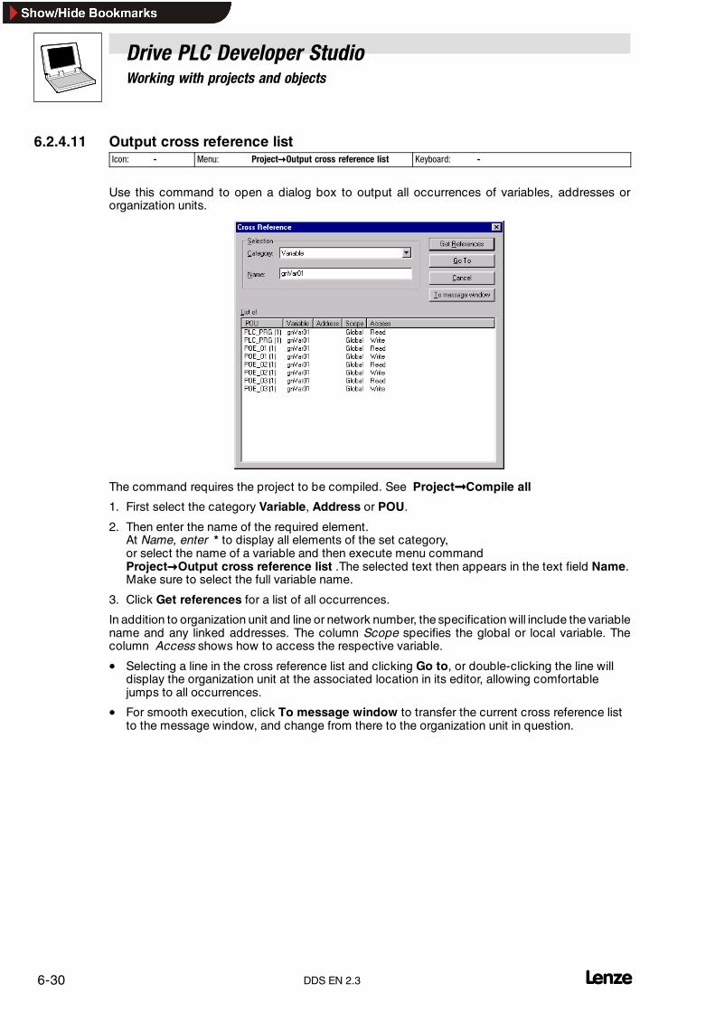
Drive PLC Developer StudioWorking with projects and objects
6-30 lDDS EN 2.3
6.2.4.11 Output cross reference listIcon: - Menu: Project�Output cross reference list Keyboard: -
Use this command to open a dialog box to output all occurrences of variables, addresses ororganization units.
The command requires the project to be compiled. See Project����Compile all
1. First select the category Variable, Address or POU.
2. Then enter the name of the required element.At Name, enter * to display all elements of the set category,or select the name of a variable and then execute menu commandProject�Output cross reference list .The selected text then appears in the text field Name.Make sure to select the full variable name.
3. Click Get references for a list of all occurrences.
In addition to organization unit and line or network number, the specification will include the variablename and any linked addresses. The column Scope specifies the global or local variable. Thecolumn Access shows how to access the respective variable.
• Selecting a line in the cross reference list and clicking Go to, or double-clicking the line willdisplay the organization unit at the associated location in its editor, allowing comfortablejumps to all occurrences.
• For smooth execution, click To message window to transfer the current cross reference listto the message window, and change from there to the organization unit in question.

Drive PLC Developer StudioWorking with projects and objects
6-31l DDS EN 2.3
6.2.4.12 Output unused variablesIcon: - Menu: Project�Output unused variables Keyboard: -
Use this command to output a list of all variables declared, but not used, in the project.
The command requires the project to be compiled. See Project����Compile all
• Select a variable and click Go to, or double-click the variable, to go to the object in which thevariable was declared.
• A message will be displayed if there are no unused variables within the project.

Drive PLC Developer StudioWorking with projects and objects
6-32 lDDS EN 2.3
6.3 Working in online mode
The commands described in this chapter are available in the menu Online after log-in. Execution ofsome commands is dependent on the active editor and the selected automation system.
6.3.1 Commands in the “Online” menu
6.3.1.1 Log inIcon: Menu: Online�Log in Keyboard: <Alt>+<F8>
Use this command to combine the programming system with the control (or start the simulationprogram) and change into online mode.
• If the current project has not been compiled since it was opened or since the last change, itwill be compiled now (in accordance with Project����Compile all). Compile errors will preventthe DDS from going into online mode.
Log-in error messages
If the error message ”No connection with the control...” is displayed
• check that the automation system set in the automation system settings (Resources) matchesthe parameter set in Online����Communication parameters.
• check the connection between PC and automation system.
• After a correct log-in, the status line display will be Online.
If the error message ”The program has been changed! Do you want to load the new program?”appears, thecurrent project in theeditor does not match the program currently loaded into thecontrol(or the launched simulation program).
• Monitoring and debugging are not possible in this case.
• Select No to log into the control. This will not load the project into the control.
• Select Yes to load the current project into the control.
6.3.1.2 Log outIcon: Menu: Online�Log out Keyboard: <Ctrl>+<F8>
Use this command to disconnect the link with the control or the simulation program and to changeinto offline mode.
6.3.1.3 LoadIcon: - Menu: Online�Download Keyboard: -
Use this command to download the program into the PLC.
• Note that a log-in will not launch a program download if the project in the DDS is identical tothe project in the PLC.

Drive PLC Developer StudioWorking with projects and objects
6-33l DDS EN 2.3
6.3.1.4 StartIcon: Menu: Online�Start Keyboard: <F5>
Use this command to start processing of the user program in the PLC or simulation.
The status line displays RUNNING after correct log-in and start.
The command can be executed under the following circumstances:
• After the user program was stopped in the control with the command Online����Stop.
• If the user program has hit a breakpoint.
• If the menu command Online�Single cycle was executed.
6.3.1.5 StopIcon: Menu: Online�Stop Keyboard: <Shift>+<F8>
Use this command to stop processing of the user program in the PLC or simulation between twocycles.
• If the program is stopped, the PLC sets quick stop (QSP).
• Use the command Online�Start to continue program processing.
6.3.1.6 ResetIcon: Menu: Online�Reset Keyboard: -
Use this command to reset variables initialized with a certain value to this value.
• All other variables are reset to a standard value (e.g. integers to 0).
• The user will be asked to confirm the variable reset.
Differences between the command Online����Reset and mains disconnection/control power-off/-on:
• Code variables will only be reset to their initialization value in case of a Reset. In case of amains disconnection, they will keep the value saved with C0003.
• From Servo PLC and Drive PLC operating system 6.0, RETAIN variables will not bere-initialized in case of a Reset or mains disconnection.In the previous version, they were re-initialized in case of a Reset.
Caution!RETAIN variables will not be initialized from Servo PLC and Drive PLC operating system 6.0.
Use the command Online����Start to restart program processing.
6.3.1.7 Reset (cold)Icon: - Menu: Online�Reset (cold) Keyboard: -
Use this command to reset all variables including the RETAIN variables to the initialization value. Onlythe persistent variables retain the value they had prior to the Reset (cold).
6.3.1.8 Reset (bootstrap)Icon: - Menu: Online�Reset (bootstrap) Keyboard: -
Use this command to reset all variables, including RETAIN and PERSISTENT, to the initializationvalue. The user program in the PLC is cleared and the PLC is returned to its original status. FromServo PLC and Drive PLC operating system 6.0.

Drive PLC Developer StudioWorking with projects and objects
6-34 lDDS EN 2.3
6.3.1.9 Breakpoint on/offIcon: Menu: Online�Breakpoint on/off Keyboard: <F9>
Use this command to set a breakpoint at the current position in the active window.
• Breakpoints can also be set by clicking the line number field.
• If the current position is already occupied by a breakpoint, this breakpoint will be removed.
• A set breakpoint is identified with a line number/network number field or step with a light bluebackground colour.
• If a breakpoint is reached during program processing, the program stops and the associatedfield is displayed with a red background colour.
• Use the following commands to continue the program Online����Start, Online����Single step inor Online����Single step over.
• Breakpoints can also be set and removed with the menu command Online����Breakpointdialog.
Warning!If program processing is stopped as a consequence of a breakpoint, the behaviour defined underProject�Exception handling will take effect for the control.
The positions where a breakpoint can be set depend on the editor:
IL, ST
In the text editors (IL, ST), breakpoints will be set to the line with the cursor if this line is a breakpointposition (indicated by the dark grey line number field).
• Another option to set or remove a breakpoint is to click the line number field.
FBD, LD
In the FBD and LD editors, breakpoints will be set to the currently selected network.
• Another option to set or remove a breakpoint is to click the network number field.
SFC
In the SFC editor, the breakpoint will be set to the currently selected step.
• To set or remove a breakpoint, double-click while keeping the <Shift> key depressed.
Note!The setting of breakpoints will affect the operating system’s processing schedule.
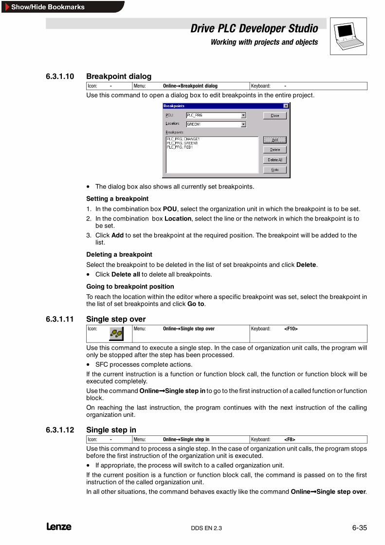
Drive PLC Developer StudioWorking with projects and objects
6-35l DDS EN 2.3
6.3.1.10 Breakpoint dialogIcon: - Menu: Online�Breakpoint dialog Keyboard: -
Use this command to open a dialog box to edit breakpoints in the entire project.
• The dialog box also shows all currently set breakpoints.
Setting a breakpoint
1. In the combination box POU, select the organization unit in which the breakpoint is to be set.
2. In the combination box Location, select the line or the network in which the breakpoint is tobe set.
3. Click Add to set the breakpoint at the required position. The breakpoint will be added to thelist.
Deleting a breakpoint
Select the breakpoint to be deleted in the list of set breakpoints and click Delete.
• Click Delete all to delete all breakpoints.
Going to breakpoint position
To reach the location within the editor where a specific breakpoint was set, select the breakpoint inthe list of set breakpoints and click Go to.
6.3.1.11 Single step overIcon: Menu: Online�Single step over Keyboard: <F10>
Use this command to execute a single step. In the case of organization unit calls, the program willonly be stopped after the step has been processed.
• SFC processes complete actions.
If the current instruction is a function or function block call, the function or function block will beexecuted completely.
Use the command Online����Single step in to go to the first instruction of a called function or functionblock.
On reaching the last instruction, the program continues with the next instruction of the callingorganization unit.
6.3.1.12 Single step inIcon: - Menu: Online�Single step in Keyboard: <F8>
Use this command to process a single step. In the case of organization unit calls, the program stopsbefore the first instruction of the organization unit is executed.
• If appropriate, the process will switch to a called organization unit.
If the current position is a function or function block call, the command is passed on to the firstinstruction of the called organization unit.
In all other situations, the command behaves exactly like the command Online����Single step over.

Drive PLC Developer StudioWorking with projects and objects
6-36 lDDS EN 2.3
6.3.1.13 Single cycleIcon: - Menu: Online�Single cycle Keyboard: <Ctrl>+<F5>
Use this command to execute a single control cycle and stop after this cycle.
• Online����Single cycle works for cyclical tasks only and will not consider the EVENT/INTERVALtasks.
• Online����Single cycle can be repeated continuously to proceed in single cycles.
• Single cycle ends if the menu command Online����Start is executed.
6.3.1.14 Write valuesIcon: - Menu: Online�Write values Keyboard: <Ctrl>+<F7>
Use this command to change the value of single-element variables.
Double-click the line in which the variable is declared, or select the line and press <Enter>.
• This will display a dialog box to specify a new value for the variable. In the case of Booleanvariables, the value will be toggled without dialog box display.
The new value (now light blue) will not be written to the control immediately.
• Change as many variables as necessary and transfer them to the PLC in one go(cycle-consistent).
1. Defining the values– In the case of non-Boolean variables, double-click the line in which the variable is declared
to open a dialog box Write variable ’Counter’(counter as example) to enter the value to bewritten to the variable.
– In the case of Boolean variables, double-click the line in which the variable is declared totoggle the value (between TRUE, FALSE and no new value) without a dialog display.
The new value to be written will be displayed in angular brackets and light blue colour behind the olddeclaration value.
Tip!The following exception applies for the display of values to be written.FBD and LD editors display a value without angular brackets and in turquoise colour next to thevariable name.
• Value definition may be performed for any number of variables.
• The values may be entered for writing, modified and deleted.
• The values to be written will be stored in a write list (watch list) until written or deleted.
2. Writing values– Menu command Online�Write values– Dialog box Edit write list and force list button Write values
Execution of Write values will write all values in the write list once-only to the associated variablesin the control at the beginning of the cycle, thus deleting the variables from the write list.
Tip!In SFC, the individual values that make up a transition expression cannot be modified with Writevalues.

Drive PLC Developer StudioWorking with projects and objects
6-37l DDS EN 2.3
Monitoring displays the overall value of the expression, not the values of the individual variables.Example:a AND b will only then be displayed as TRUE if both variables are TRUE.
In FBD, only the first variable of an expression, that may be used as input of a function block, forexample, becomes visible (monitor). Write values is possible for this variable only.
Write values writes changed values to the control once-only where they can be overwritten againimmediately.
6.3.1.15 Call hierarchyIcon: - Menu: Online�Show Call Stack Keyboard: -
If simulation stops at a breakpoint, use this command to open a dialog box that lists the organizationunits currently in the call stack.
• The first organization unit is always PLC_PRG as this is where processing starts.
• The last organization unit is always the organization unit that is currently being processed.
Select an organization unit and click Go to to load the selected organization unit into a window andto display the line or network that is currently processed.
6.3.1.16 SimulationIcon: - Menu: Online�Simulation Keyboard: -
Selection of Simulation puts a tick � in front of the menu item.
In simulation mode, the user program will run under Windows on the same PC. Simulation tests theproject. Communication between PC and simulation uses the Windows Message Mechanism.
If the program is not in simulation mode, it will run on the control. Communication between PC andcontrol uses a gateway. The status of this flag is stored with the project.
Restrictions for simulation
If all tasks are to be considered during simulation, adapt the interval times accordingly.The following projects are restricted during simulation or cannot be simulated.
• Lenze function blocks
• System organization units
6.3.1.17 Communication parametersIcon: - Menu: Online�Communication parameters Keyboard: -
Use this command to create and manage communication channels to the automation system.
Note!Use of the OPC or DDEserver requires the same communication parameters to be set in that server’sconfiguration.

Drive PLC Developer StudioWorking with projects and objects
6-38 lDDS EN 2.3
The following channels to the automation system are currently available for practical use:
• Local gateway• Remote gateway
Via a TCP/IP network to a remote gateway PC with parallel port and dongle.
PC_lokal
PC_x
PC_GatewayTCP/IP /‘local (shared memory)'
PC_PLC1
PC_PLC2
PC_PLC3
PC_PLC4
TPC/IP,Pipe,etc.
The dialog box Communication parameters is divided into four panes:
1. Channels
This is where the communication channels from the local host are displayed and those to be editedare selected.
2. Communication driver display
The currently loaded communication driver (e. g. “CAN 8220 | JumpingLEDs.pro”).
3. Communication parameters
The parameters set for the currently loaded communication driver.
4. Buttons
OK Quit and accept parameters
Cancel Quit and reject parameters
New... Create a new communication channel, via the parallel port/system bus dongle, for example
Remove Remove a channel selected in pane ChannelsGateway Create a new communication channel to a remote gateway PC
Update Check parameters or update the display
Creating a communication channel via the system bus dongle
The most commonly used communication option is via the system bus dongle connected to a localPC via the parallel port.
Two parameters must be known to establish a connection to a certain automation system (e. g. 9300Servo PLC) within a CAN bus network:
• The device address on the bus (CAN bus node address). The device address is stored in codeC0350 of the automation system and must match the setting of the communication channel.
• The baud rate set on the bus (CAN bus baud rate). The device address is stored in codeC0351 of the automation system and must match the setting of the communication channel.

Drive PLC Developer StudioWorking with projects and objects
6-39l DDS EN 2.3
Note!The Lenze default setting for DDS and automation system is a baud rate of 500 KBaud.
Creating a channel with default parameters
Select Communication parameters and click localhost����Lenze standard and then OK.
Creating a communication channel with the Lenze CAN driver
1. Click New to configure a new localhost channel.
2. Select Communication parameters: New channel and click CAN 8220:
3. Click OK.
4. Select the new channel and enter the defined /required parameters in Communicationparameters by clicking the relevant entry and select the parameters using the arrow keys.
5. Accept the settings with OK.(This parameterizes and starts the communication driver GATEWAY.EXE.)
Creating a communication channel with the OPC system bus driver
1. Click New to configure a new channel.
2. Select Communication parameters: New channel, list field Device and click SystembusServer Driver.
3. Click OK.
4. Use the entry Hardware Number to select a specific port. If 0 is entered, the standard portwill be used.Use the communication tool System bus configurator to determine:– how many active ports are available– the individual port numbers– the standard port

Drive PLC Developer StudioWorking with projects and objects
6-40 lDDS EN 2.3
5. Use the entry Can bus node address to select a device address.The device address is stored in code C0530 of the automation system and must match thedevice address of the communication channel.
6. Accept the settings with OK. This parameterizes and starts the communication driverGATEWAY.EXE.
Creating a communication channel via a TCP/IP network to a remote gateway PC
Access to a remote PC (remote gateway PC) with system bus dongle is possible from the DDS viaa TCP/IP network.
Thus all functions under a direct CAN bus access (such as program download, monitoring, etc.)canbe executed via the network.
For this purpose, the communication channel from the gateway PC to the automation system mustbe set up properly at the gateway PC, and the communication driver GATEWAY.EXE must run on theremote gateway PC (see “Creating a communication channel via the system bus dongle”).
• A remote change of the communication parameters on the gateway PC via the TCP/IPnetwork is currently not possible.
• The IP address of the remote PC in the network must be known to create a connection to agateway PC.
Finding out the IP address of the gateway PC
Contact your network administrator for the IP address (or open the program “ IPCONFIG” in a DOSwindow on the gateway PC).
Creating a channel to the gateway PC via a TCP/IP network
1. Select Communication parameters and click local.2. Click Gateway to open the dialog box Communication parameters: Gateway:
3. Enter the IP address of the gateway PC and click OK.
Channels displays the IP address of the gateway PC and Communication parameters theparameters set on the PC.
• If “(Not connected)” is displayed behind the IP address, the communication driverGATEWAY.EXE is not running on the gateway PC. Start the driver from the DDS on thegateway PC.
Removing a communication channel via a TCP/IP network to a remote gateway PC
Proceed as follows to remove a connection to a remote gateway PC and return to the local gateway:
1. Select the IP address in Communication parameters under Communication parameters.
2. Click Gateway to open the dialog box Communication parameters: Gateway.3. Use the input field Address to enter” localhost” and click OK.
Unsuccessful communication setup
An unsuccessful attempt to set up communication with the gateway server on a different PC. Thefollowing aspects must be met for correct communication setup.
• The tri-colour icon in the lower menu bar shows the active gateway server.
• Was the correct IP address entered in the dialog box Communication parameters: Gateway?
• The local TCP/IP connection must work.

Drive PLC Developer StudioWorking with projects and objects
6-41l DDS EN 2.3
6.3.1.18 Controller enableIcon: - Menu: Online�Controller enable Keyboard: -
Use this command to enable the controller.
The menu item will be deactivated for automation systems without controller inhibit.
• In GDC, this function corresponds to the key Start.
Warning!Do not use the commands Controller enable/Controller inhibit for an emergency stop via the PCas these commands reach the controller with a delay.
In the DDS, these commands are added to the end of a message queue so that they will reach thecontroller with a delay of several seconds in a worst-case scenario.
6.3.1.19 Controller inhibitIcon: - Menu: Online�Controller inhibit Keyboard: -
Use this command to inhibit the controller.
The menu item will be deactivated for automation systems without controller inhibit.
• In GDC, this function corresponds to the key ”Stop” .
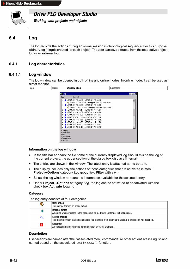
Drive PLC Developer StudioWorking with projects and objects
6-42 lDDS EN 2.3
6.4 Log
The log records the actions during an online session in chronological sequence. For this purpose,a binary log (*.log) is created for each project. The user can save extracts from the respective projectlog in an external log.
6.4.1 Log characteristics
6.4.1.1 Log window
The log window can be opened in both offline and online modes. In online mode, it can be used asdirect monitor.Icon: - Menu: Window�Log Keyboard: -
Information on the log window
• In the title bar appears the file name of the currently displayed log.Should this be the log ofthe current project, the upper section of the dialog box displays [Internal].
• The entries are shown in the window. The latest entry is attached at the bottom.
• The display includes only the actions of those categories that are activated in menuProject�Options category Log group field Filter with a (�).
• Below the log window appears the information available for the selected entry.
• Under Project�Options category Log, the log can be activated or deactivated with thecheck box Activate logging.
Category
The log entry consists of four categories.User actionThe user performed an online action.
Internal actionAn action was performed in the online shift (e. g., Delete Buffers or Init Debugging).
Status changeThe runtime system status has changed (for example, from Running to Break if a breakpoint was reached).
ExceptionAn exception has occurred (a communication error, for example).
Description
User actions are named after their associated menu commands. All other actions are in English andnamed based on the associated OnlineXXX() function.

Drive PLC Developer StudioWorking with projects and objects
6-43l DDS EN 2.3
Information
This field describes errors that occur during an action. The field remains blank if no errors occur.
System time
The current system time on action start.
Relative time
The relative time at online session start.
Duration
The duration of the action in milliseconds.
6.4.1.2 Log menu
If the input focus is on the log window, the menu commandLog is shown in the menu bar instead of Insert. Extras remains preserved but blank.
6.4.1.3 LoadIcon: - Menu: Log �Load Keyboard: -
An external log (*.log) can be loaded and displayed via the standard Windows file opening dialog.
• The log within the project will not be overwritten by the command.
• The loaded version will be replaced with the project log if– the log window is closed and re-opened.– a new online session is started.
6.4.1.4 SaveIcon: - Menu: Log�Save Keyboard: -
This command can be selected only if the project log is displayed and can be used to save a projectlog extract into an external file. The sessions must be selected to be saved.
Pressing OK returns the standard Windows file save dialog.
6.4.1.5 Display project logIcon: - Menu: Log�Display project log Keyboard: -
This command can be selected only if an external log is currently displayed and switches thedisplayback to the project log.
6.4.1.6 Saving the project log
The project log is automatically saved in a binary file projectname.log independently of a logsave to an external file.
Use menu command Project�Options category Log to specify a save path. If no path is specified,the log will be saved in the same directory that already stores the project.
Use menu command Project�Options category Log to specify the number of online sessions viatext field Maximum project log size. If the number is exceeded, the earlier ones will be removedin favour of the later ones in accordance with the first-in-first-out principle.

Drive PLC Developer StudioWorking with projects and objects
6-44 LDDS EN 2.3

Drive PLC Developer StudioEditors
7-1l DDS EN 2.3
7 Editors
7.1 General edit functions
The commands described in this chapter are available in all editors under menu Edit and in somecases also via the shortcut menu in the Object Organizer.
Printer borders
Menu command Project�Options, category Desktop includes the check box Printer borders.This feature allows the printable area of the individual editors to be outlined in red, subject to thespecifications of the set printer and the template size selected in the menu commandFile�Documentation setup .
Default settings will apply where no printer or documentation size is set (default.DFR and standardprinter).
The horizontal printer borders are drawn as if, in the dialog box Documentation Setup, the checkbox New page for each object or New page for each subobject were selected. The bottommargin is not displayed.
Tip!Set the zoom factor to 100 % to ensure exact printer border display.
7.1.1 Commands in the “Edit” menu
7.1.1.1 UndoIcon: - Menu: Edit �Undo Keyboard: <Ctrl>+<Z>
Use this command to undo the last action in the currently open editor window or in the ObjectOrganizer .
All actions executed since the window was opened can be undone by repeating execution of thiscommand.
• This applies to all actions in the editors for organization units, data types, visualizations andglobal variables and in the Object Organizer.
Use Edit����Redo to redo an undone action.
Tip!The commands Undo and Redo always act on the currently open window.
Each window has its own action list. Activate the associated window to undo actions in severalwindows.
Undo’s or redo’s in the Object Organizer require the Object Organizer to be the active window.
7.1.1.2 RedoIcon: - Menu: Edit �Redo Keyboard: <Ctrl>+<Y>
Use this command to redo an action undone with Edit����Undo in the currently open editor windowor in the Object Organizer.
• The command Redo can be executed as often as the command Undo before.

Drive PLC Developer StudioEditors
7-2 lDDS EN 2.3
7.1.1.3 CutIcon: Menu: Edit �Cut Keyboard: <Ctrl>+<X>
<Umschalt>+<Del>
Use this command to remove the current selection from the editor and save it to the clipboard.
• In the case of the Object Organizer , this applies analogously to selected objects, althoughsome objects cannot be cut (such as the PLC configuration, for example).
Note!Note that not all editors support the cut function, and that the functionality may be limited in someeditors.
The selection format depends on the editor:
• In text editors (IL, ST, declaration), the selection is a sequence of characters.
• In the FBD, LD and CFC editors, the selection is a number of networks identified by a dottedrectangle in the network number field or a box with all lines, boxes and operands.
• In the SFC editor, the selection is part of a step sequence surrounded by a dotted rectangle.
The contents of the clipboard can be inserted by using the command Edit����Insert.
• The SFC editor also allows use of the commands Extras����Insert parallel branch (right) orExtras����Insert after.
7.1.1.4 CopyIcon: Menu: Edit �Copy Keyboard: <Ctrl>+<C>
<Ctrl>+<Insert>
Use this command to copy the current selection from the editor to the clipboard. The contents ofthe editor window will not be changed.
• In the case of the Object Organizer , this applies analogously for selected objects, althoughsome objects cannot be copied (such as the PLC configuration, for example).
Tip!Note that not all editors support the copy function, and that the functionality may be limited in someeditors.
The selection format depends on the editor:
• In text editors (IL, ST, declaration), the selection is a sequence of characters.
• In the FBD, LD and CFC editors, the selection is a number of networks identified by a dottedrectangle in the network number field or a box with all lines, boxes and operands.
• In the SFC editor, the selection is part of a step sequence surrounded by a dotted rectangle.
The contents of the clipboard can be inserted by using the command Edit����Insert.
• The SFC editor also allows use of the commands Extras����Insert parallel branch (right) orExtras ����Insert after.

Drive PLC Developer StudioEditors
7-3l DDS EN 2.3
7.1.1.5 InsertIcon: Menu: Edit �Insert Keyboard: <Ctrl>+<V>
<Umschalt>+<Insert>
Use this command to insert the contents of the clipboard at the current position in the editor window.
• With graphically oriented editors, this command can be used only if insertion produces acorrect structure.
• In the case of the Object Organizer, the object is inserted from the clipboard.
Tip!Note that not all editors support the insert function, and that the functionality may be limited in someeditors.
Clipboard contents may be inserted at different locations, insertion being dependent on theassociated editor.
• In the case of text editors (IL, ST, declaration), the current location is the position of theflashing cursor (a small vertical line that can be positioned with the mouse).
• In the case of FBD, LD and CFC editors, the current position is the first network with a dottedrectangle in the network number range. The contents of the clipboard are inserted in front ofthis network. Any part of a structure, that was copied, will be inserted in front of the selectedelement.
• With the SFC editor, the current position is determined by the selection surrounded by adotted rectangle. Dependent on the selection and the clipboard contents, the clipboardcontents will be inserted in front of this selection or in a new branch (parallel or alternative) tothe left of the selection.
• The SFC editor also allows use of the commands Extras����Insert parallel branch (right) orExtras����Insert after.
7.1.1.6 DeleteIcon: - Menu: Edit �Delete Keyboard: <Del>
Use this command to delete the selected range from the editor window. The contents of theclipboard will not be changed.
• In the case of the Object Organizer , this applies analogously to selected objects, althoughsome objects can not be deleted (such as the PLC configuration, for example).
The selection format depends on the editor:
• In text editors (IL, ST, declaration), the selection is a sequence of characters.
• In the FBD, LD and CFC editors, the selection is a number of networks identified by a dottedrectangle in the network number field.
• In the SFC editor, the selection is part of a step sequence surrounded by a dotted rectangle.
• In the Library Manager, the selection is the currently selected library name.

Drive PLC Developer StudioEditors
7-4 lDDS EN 2.3
7.1.1.7 FindIcon: Menu: Edit�Find Keyboard: <Ctrl>+<F>
Use this command to find a character sequence in the current editor window.
Selection of the command opens the dialog box Find.
• The dialog box Find remains open until Cancel is clicked.
Find what
Use the input field Find what to enter the character sequence to be found.
Match whole word only
Select whether the text to be found is a whole word or also part of a word.
Match case
Select whether the search is to be case-sensitive or not.
Direction
Select whether the search is to be up or down from the current cursor position.
Start search
Click Find next to start the search.
Search starts at the selected position and is performed in the selected direction.
• Any found text occurrence will be highlighted.
• Unsuccessful searches will be notified.
Tip!The search can be repeated by clicking Find next again and will stop on reaching the beginningor end of the editor window contents.
Note that the text found may be hidden behind the dialog box Find .
7.1.1.8 Find nextIcon: Menu: Edit �Find next Keyboard: <F3>
Use this command to search the text using the same parameters as before with the commandEdit����Find.

Drive PLC Developer StudioEditors
7-5l DDS EN 2.3
7.1.1.9 ReplaceIcon: - Menu: Edit �Replace Keyboard: <Ctrl>+<H>
Use this command to find a character sequence in the current editor window and replace it withanother sequence.
Selection of the command opens the dialog box Replace.
• The dialog box Replace remains open until Cancel is clicked.
Find what
Use the input field Find what to enter the character sequence to be found.
Replace with
Use the input field Replace with to enter the character sequence which is to replace the text to befound.
Match whole word only
Select whether the text to be found is a whole word or also part of a word.
Match case
Select whether the search is to be case-sensitive or not.
Start search
Click Find next to start the search.
The search starts at the current position.
• Any found text occurrence will be highlighted.
• Unsuccessful searches will be notified.
Replace
Click Replace to replace the currently selected text with the text in Replace with.
Replace all
Click Replace all to replace all text occurrences found behind the current location with the text inReplace with.

Drive PLC Developer StudioEditors
7-6 lDDS EN 2.3
7.1.1.10 Help ManagerIcon: - Menu: Edit�Help Manager Keyboard: <F2>
Use this command to open the dialog box Help Manager for a display of possible inputs at thecurrent cursor position in the editor window.
1. Select the input category from the column on the left.
2. Select the required entry in the column on the right.
3. Click OK to confirm the selection.
The selection will be inserted at the current cursor position.
• The Help Manager is context-sensitive, i.e. the categories available depend on the currenteditor window and the current cursor position.
• With arguments
• In the case of this option, the arguments to be transferred are also specified on insertion ofthe selected element.
Examples:
Selection of function block fu1 with defined input variable var_in:fu1(var_in:=);Insertion of function func1 that requires var1 and var2 as transfer parameters:func1(var1, var2);
Toggling between structured and non-structured representation of the available elements ispossible on principle by activating/deactivating the option Structured.
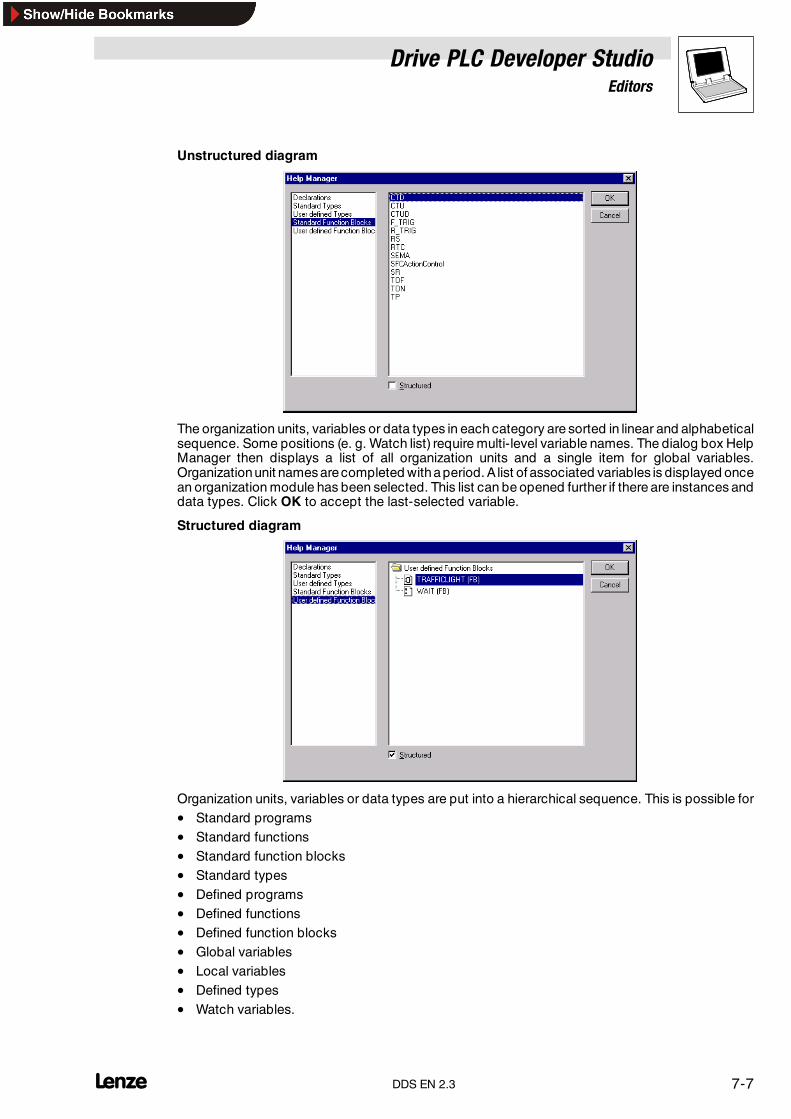
Drive PLC Developer StudioEditors
7-7l DDS EN 2.3
Unstructured diagram
The organization units, variables or data types in each category are sorted in linear and alphabeticalsequence. Some positions (e. g. Watch list) require multi-level variable names. The dialog box HelpManager then displays a list of all organization units and a single item for global variables.Organizationunit names arecompleted withaperiod. A list of associated variables is displayed oncean organization module has been selected. This list can be opened further if there are instances anddata types. Click OK to accept the last-selected variable.
Structured diagram
Organization units, variables or data types are put into a hierarchical sequence. This is possible for• Standard programs• Standard functions• Standard function blocks• Standard types• Defined programs• Defined functions• Defined function blocks• Global variables• Local variables• Defined types• Watch variables.

Drive PLC Developer StudioEditors
7-8 lDDS EN 2.3
Visual and hierarchical representation is in unison with that of the Object Organizer. Any elementswithin libraries are inserted alphabetically at the top, and the respective hierarchy is displayed asin the Library Manager.
The input and output variables of function blocks that are declared as local or global variables, arelocated in the form of a list underneath the instance name in the Local variable or Global variablecategory.
• Inst_TP.ET
• Inst_TP.IN
Inst_TP can be expanded like an Explorer directory.
With arguments
If the check box is selected, the instance name and the input parameters of the function block willbe inserted for the ST and IL text languages and in task configuration.Selection of Inst (DeclarationInst:TON;) insertsInst(IN:=, PT:=, Q=>, ET=>);.
:= Assign function block inputs
=> Assign function block outputs
If the check box is not selected, only the instance name will be inserted. In general, only the instancename will be inserted in the case of graphic languages or in the Watch window.
Components of structures are represented analogously to the function block instances.
Enumerations list the individual values underneath the respective type, adhering to the followingsequence:Enumerations from libraries, from data types, local enumerations from organization units.
Note!Some entries (e. g. global variables) will only be updated in the Help Manager after a compile.
7.1.1.11 Next faultIcon: - Menu: Edit�Next fault Keyboard: <F4>
Use this command to display the next error after a project compiled with errors.
• The associated editor window is activated and the error location highlighted.
• The associated error message will be displayed in the message window at the same time.
• Warnings may be ignored on single-stepping with F4.Project�Options category Desktop check box F4 ignores warnings.
7.1.1.12 Previous faultIcon: - Menu: Edit�Previous fault Keyboard: <Umschalt>+<F4>
Use this command to display the previous error after a project compiled with errors.
• The associated editor window is activated and the error location highlighted.
• The associated error message will be displayed in the message window at the same time.
• Warnings may be ignored on single-stepping with <Umschalt>+<F4>.Project�Options category Desktop check box F4 ignores warnings.

Drive PLC Developer StudioEditors
7-9l DDS EN 2.3
7.1.1.13 MacrosIcon: - Menu: Edit�Macros Keyboard: -
This menu item lists all macros agreed for the current project. New macros can be created underProject�Options category Macros. Selection of an executable macro opens dialog box Processmacro. Macro name and current command line are displayed. Use Cancel to stop the macro. Thecurrent command line will still be processed.
The message window will show a message that will be logged in online mode.Macro canceled.
Macros may be processed both online and offline. Only the commands available in the respectivemode will be executed.

Drive PLC Developer StudioEditors
7-10 lDDS EN 2.3
7.2 Declaration editor
The declaration editor is used to declare variables of organization units and global variables, for datatype declaration and in the Watch and Receipt Manager. It offers Windows and IntelliMousefunctionalities, but requires the associated driver to do so.
The overtype mode is displayed in the status bar with OVR. Press <Insert> to toggle betweenoverwrite and insert modes.
• Variable declaration is supported by the use of various colours. Keywords are written in blueletters.
• In all editors for organization units, a horizontal screen divider separates declaration part frombody on screen. This divider can be moved as required by keeping the left mouse keydepressed.
Tip!The most essential declaration editor commands are also available in the shortcut menu(right mouse key or <Umschalt>+<F10>).
Declarations as tables
Instead of the declaration editor, use menu item Project�Options, category Editor to edit variablesas a table with the help of selecting check box Declarations as tables. (� 7-18)
• This table is arranged as a card index box with tab cards for input variables (VAR_INPUT),output variables VAR_OUTPUT, local variables VAR and input / output variables VAR_INPUT.
• Fields for name, address, type, initial value and comment are available for each variable.

Drive PLC Developer StudioEditors
7-11l DDS EN 2.3
7.2.1 Declaration part
The declaration part of an organization unit declares all variables locally.
These may be
• input variables,
• output variables,
• input / output variables,
• local variables,
• retentive variables,
• constants
• and retentive constants.
The declaration syntax is based on the IEC 61131-3 standard.
7.2.1.1 Declaration keywordsIcon: - Menu: Insert�Declaration keywords Keyboard: -
Use this command to open a list of all keywords available for use in the declaration part of anorganization unit.
• The keyword will be inserted at the current cursor position once it has been selected andconfirmed.
• The list will also be displayed when calling the Help Manager and selecting the categoryDeclarations.
7.2.2 Input variables
Between the keywords VAR_INPUT and END_VAR, all variables are declared that are used as inputvariables for an organization unit.
• The values of these variables can be transferred from the calling unit.
Example:
VAR_INPUTin1:INT; (* 1. input variable *)END_VAR
Input variables can be used to transfer data from the calling to the called organization unit.
7.2.3 Output variables
Between the keywords VAR_OUTPUT and END_VAR, all variables are declared that are used asoutput variables for an organization unit.
• The values of these variables are returned to the calling organization unit for further use.
Example:
VAR_OUTPUTout1:INT; (* 1. output variable *)END_VAR

Drive PLC Developer StudioEditors
7-12 lDDS EN 2.3
7.2.4 Input / output variables
Between the keywordsVAR_IN_OUTand END_VAR, all variables are declared that are used as inputand output variables for an organization unit.
Note!In the case of these variables, the value of the transferred variables is changed directly (”Transferas pointer” , call-by-reference). Therefore, the input value for these variables must not be aconstant.For this reason, VAR_IN_OUT variables of a function block can not be read directly from outside viaFunction block instance, Input / output variable.
Example:
VAR_IN_OUTinout1:INT; (* 1. input / output variable *)END_VAR
7.2.5 Local variables
Between the keywords VAR and END_VAR, all local variables of an organization unit are declared.
• Local variables have no connection to the outside, i. e., they cannot be written from outside.
Example:
VARloc1:INT; (* 1. local variable *)END_VAR
7.2.6 Retentive variables
Retentive variables may retain their value beyond the standard program runtime. Retentivevariables include Retain variables and persistent variables.
Retain variables
All retain variables of an organization unit are declared between the keywords VAR Retain andEND_VAR.
• Retain variables retain their values after a control disconnect or after a reset. When theprogram is restarted, the stored values are used for further processing.
• In two cases the retain variables are reset to their initialization values.– With a program download.– In online mode with the menu commands Online Reset (cold) and Online Reset (bootstrap).
Persistent variables
Persistent variables are stored in the persistent memory and retain their values. The persistentmemory can only be cleared in online mode via the menu command Online Reset (bootstrap).
The persistent memory can be accessed via the system organization unit Var_Persistent.
In the Object Organizer, tab Resources you can open the PLC configuration. Use the menucommand Insert Add subelement Var_Persistent... to add the system organization unit as asubelement.

Drive PLC Developer StudioEditors
7-13l DDS EN 2.3
Application example
An operating hour meter that is to continue counting after a mains failure.
• All other variables will be re-initialized either with the standard initial values (0 or FALSE) orwith the defined initial values.
Example:
VAR RETAINrem1:INT; (* 1. retentive variable *)END_VAR
7.2.7 Constants, typed literals
Between the keywords VAR CONSTANT and END_VAR, all constants are declared.
• Constants can be declared locally or globally.
Syntax:
VAR CONSTANT<Identifier>:<Type> := <Initialization>;END_VAR
Example:
VAR CONSTANTcon1:INT:=12; (* 1. constant *)END_VAR
For a list of permitted constants refer chapter on Operands. (� 13-1)
7.2.8 Retentive constants
Between the keywords VAR CONSTANT RETAIN and END_VAR, all retentive constants aredeclared.
• Retentive constants can be declared locally or globally.
Syntax:
VAR CONSTANT RETAIN<Identifier>:<Type> := <Initialization>;END_VAR
Example:
VAR CONSTANT RETAINAcceleration: DINT:=10000; (* acceleration time *)END_VAR
7.2.9 Keywords
• All editors require keywords to be written in capitals.
• Keywords must not be used as variable names.
Drive PLC Developer StudioEditors
7-14 lDDS EN 2.3
7.2.10 Identifiers
Note!Only the first 32 characters are of any significance!
Identifiers are a sequence of letters, digits and underscores starting with a letter or an underscore.
Variable identifiers must not:
• contain white spaces and umlauts,
• be declared twice
• be identical to keywords.
Furthermore:
• Case sensitivity is not an option for variables.(Example: VAR1, Var1 and var1 are not different variables)
• Underscores in an identifier are significant.(Example: A_BCD and AB_CD are interpreted as different identifiers.)
• Multiple successive underscores at the beginning of or within an identifier are not allowed.
7.2.11 Variable declaration
Syntax:
<Identifier> {AT <Address>}:<Type> {:= <Initialization>};
The parts in curly brackets {} are optional.
All variable declarations and data type elements may contain initializations.
• Initializations are effected with assignment operator ” :=” .
• Initializations are constants for variables of elementary types.
• The default initialization for all declarations is 0 or FALSE.
Example:
var1: INT:=12; (* integer variable with initial value 12*)
• If the variable is to be directly linked to a certain address, the variable must be declared withthe keyword AT.
• Use the short form mode for quick entry of declarations.
• In function blocks, variables may also be specified with incomplete address details. Use ofsuch variables in local instances requires respective entries in the variable configuration.
Note the automatic declaration option.
Tip!Observe the information given in chapter IEC 61131-3 Operands for variable identifiers. (� 13-4)
Drive PLC Developer StudioEditors
7-15l DDS EN 2.3
7.2.11.1 Types for variable declarationIcon: - Menu: Insert�Types Keyboard: -
Use this command to display a selection of types available for variable declaration.
• Use of the Help Manager will also display this list.
The types are divided into the following categories:
• Standard types ( BOOL, BYTE, etc.)
• Defined types (structures, enumeration types, etc.)
• Standard function blocks (for the declaration of instances)
• Defined function blocks (for the declaration of instances)
The DDS supports all IEC 61131-3 standard types.
7.2.12 AT declaration
If the variable is to be directly linked to a certain address, the variable must be declared with thekeyword AT.
The advantage of such an approach is that an address may be assigned a more explicit name, andthat any changes to an input or output signal need be made at one location only (in the declaration).
Tip!Note that no write access is possible to variables assigned to an input.
Furthermore, AT declarations can be made for local and global variables only, not for the input andoutput variables of organization units.
Examples:
bTrip_b AT %QX1.0.0: BOOL;bRight_b AT %IX1.0.1: BOOL;bReverse_b AT %MX2.2: BOOL;
Tip!Boolean variables assigned to a byte, word or DWORD address subject a whole byte to TRUE orFALSE. not just the first bit after the offset.
7.2.13 Syntax colouring
All editors provide visual assistance for implementation and variable declaration.
• Coloured text helps to avoid errors or detect errors faster. (Unfinished comments will bedetected immediately, keywords will be written correctly, etc.)
The following colour code is applied:
Blue Keywords
Green Comments in text editors
Pink Boolean values (TRUE, FALSE)
Red Incorrect input (e. g. invalid time constant, keyword written in lower case ...)
Black Variables, constants, assignment operators ...

Drive PLC Developer StudioEditors
7-16 lDDS EN 2.3
7.2.14 Short mode
The declaration editor provides the possibility to use the short form mode.
• The short form mode is activated by completing a line with <Ctrl>+<Enter>.
The following short forms are supported:
• All identifiers except the last one in a line become variable identifiers in the declaration.
• The declaration type is determined by the last identifier in the line, where:
B or BOOL is BOOLI or INT is INTR or REAL is REALS or STRING is STRING
• If these rules did not help to define a type, the type will be BOOL and the last identifier is notused as a type (�).
• Each constant becomes an initialization or a string length depending on the declaration type(�, �).
• An address (as in %MD12) is extended by the AT attribute (�).
• A text behind a semicolon (;) becomes a comment (�).
• All other characters in the line are ignored (such as the exclamation mark in in �, forexample).
Examples:
Short form Declaration
� A A: BOOL;� A B I 2 A, B: INT := 2;
� ST S 2; String ST: STRING(2); (* String *)
� X %MD12 R 5; Number X AT %MD12:REAL := 5.0; (* Number *)
� B! B: BOOL;
7.2.15 Auto declaration
If the option Auto declaration in the dialog box Option, category Editor is activated, the followingdialog box will appear in all editors on entry of a not-yet-declared variable.
• Use combination box Class to select the variable class.
• Enter the variable name in text field Name (the input field is pre-assigned with the variablename entered in the editor).
• Enter the variable type in text field Type (the input field is pre-assigned with type BOOL).
• Use the button ... to call the Help Manager for a selection of all available types.
• Use text field Initial value to assign a value to the variable, otherwise the standard initialvalue will be used.
• Use check boxes CONSTANT (constant) and RETAIN (battery support) to define whether thequantity is a constant or a retentive Retain variable.

Drive PLC Developer StudioEditors
7-17l DDS EN 2.3
If dialog box Type is used to select variable ARRAY, a dialog is displayed for array boundarydefinition. The illustration below shows a two-dimensional UDINT-type (unsigned double integer)array.
This organization unit can beused to generate a three-dimensional array. Use Start andEnd to definethe boundaries of each dimension.
Use the button ... to define the array data type. If the dialog is exited with OK, the system generatesan IEC-format variable declaration.
Example: ARRAY[0..5, 0..2] OF INT
The variable declaration dialog offers dialog box Initial value to enter an initial value for the variableto be declared. If this is an array or a structure, button ... or <F2> (cursor must be in dialog boxInitial value) can be used to open a special initialization dialog. Other types (INT, BYTE) respond toopening the Help Manager dialog.
The initialization dialog for an array lists the array elements. A mouse click behind the := opens anedit box to enter the initial value.
The initialization dialog for a structure displays the individual components in a tree diagram wherethe variable name is followed by component type and default initial value in brackets, and an :=.Clicking behind here opens an edit box where the desired initial value may be entered. If thecomponent is an ARRAY, the initialization dialog can be opened by clicking on the plus sign to enterinitial values.
If the initialization dialog is exited with OK, the box Initial value displays the initialization of array orstructure in IEC format.
Example: x:=5,field:=2,3,struct2:=(a:=2,b:=3)
Use field Address to bind the variable to be declared to an IEC address (AT declaration). Use inputfield Comment to enter information, such as changes, for example. Use <Ctrl> +<Enter> for linebreaks.
Use OK to close the declaration dialog and to accept the entry to the variable (in accordance withIEC syntax) in the associated declaration editor.
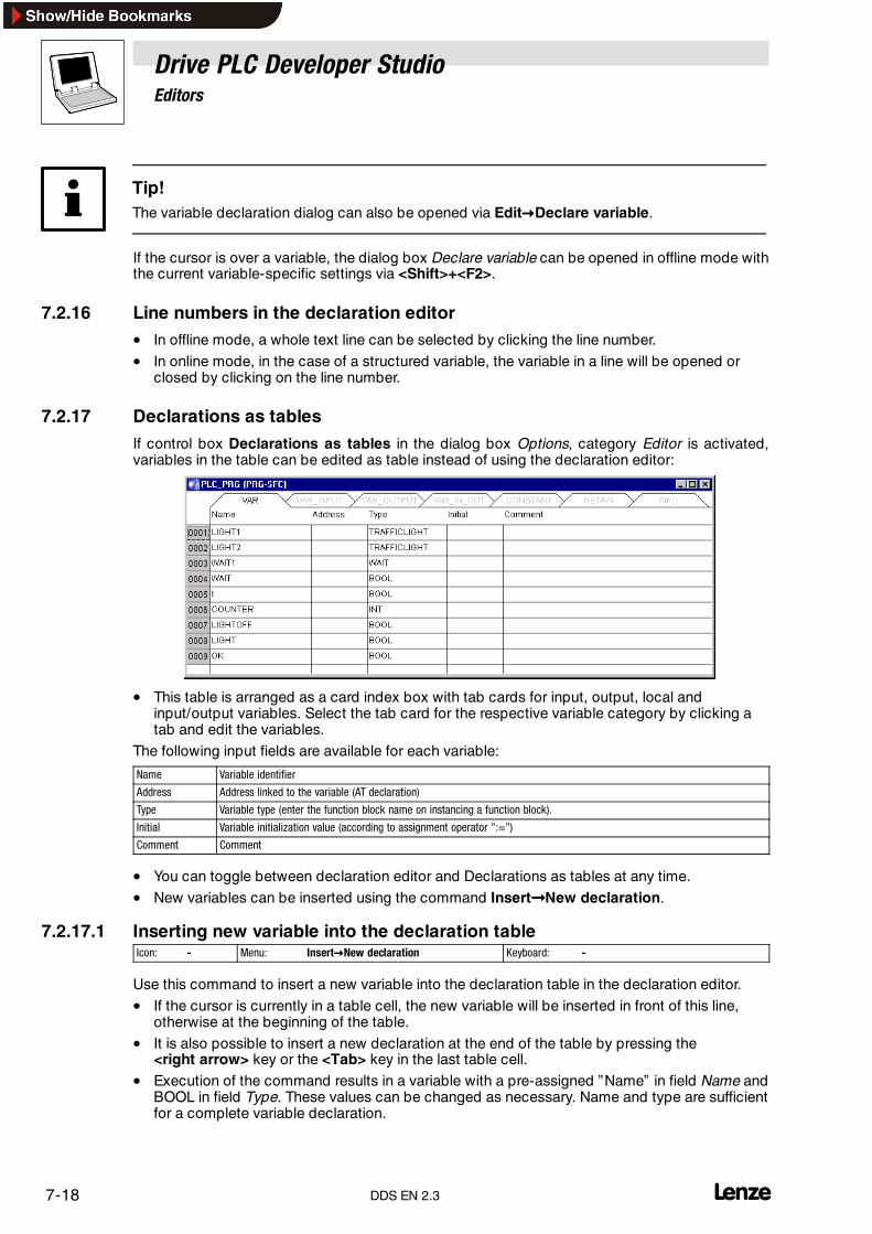
Drive PLC Developer StudioEditors
7-18 lDDS EN 2.3
Tip!The variable declaration dialog can also be opened via Edit�Declare variable.
If the cursor is over a variable, the dialog box Declare variable can be opened in offline mode withthe current variable-specific settings via <Shift>+<F2>.
7.2.16 Line numbers in the declaration editor• In offline mode, a whole text line can be selected by clicking the line number.
• In online mode, in the case of a structured variable, the variable in a line will be opened orclosed by clicking on the line number.
7.2.17 Declarations as tables
If control box Declarations as tables in the dialog box Options, category Editor is activated,variables in the table can be edited as table instead of using the declaration editor:
• This table is arranged as a card index box with tab cards for input, output, local andinput/output variables. Select the tab card for the respective variable category by clicking atab and edit the variables.
The following input fields are available for each variable:
Name Variable identifier
Address Address linked to the variable (AT declaration)
Type Variable type (enter the function block name on instancing a function block).
Initial Variable initialization value (according to assignment operator ”:=”)
Comment Comment
• You can toggle between declaration editor and Declarations as tables at any time.
• New variables can be inserted using the command Insert����New declaration.
7.2.17.1 Inserting new variable into the declaration tableIcon: - Menu: Insert�New declaration Keyboard: -
Use this command to insert a new variable into the declaration table in the declaration editor.
• If the cursor is currently in a table cell, the new variable will be inserted in front of this line,otherwise at the beginning of the table.
• It is also possible to insert a new declaration at the end of the table by pressing the<right arrow> key or the <Tab> key in the last table cell.
• Execution of the command results in a variable with a pre-assigned ”Name” in field Name andBOOL in field Type. These values can be changed as necessary. Name and type are sufficientfor a complete variable declaration.

Drive PLC Developer StudioEditors
7-19l DDS EN 2.3
7.2.18 Declaration editor in online mode
In online mode, the declaration editor is a monitor window.
Every line contains a variable followed by an equal sign (=) and the variable value.
• Three question marks (???) will appear if the variable has not been defined yet.
Multi-element variables
Multi-element variables are identified with a plus sign.
• Press <Enter> or double-click the variable to open it and to list all components. The variablewill then be identified with a minus sign.
• Double-click or press <Enter> again to hide the components and to return the plus sign.
Single-element variables
Press <Enter> or double-click asingle-element variable to open the dialog box for writing avariable.The current variable value can be changed by entering a new value. In the caseof Booleanvariables,the value will be toggled without dialog box display.
The new value (now represented in a different colour) will not be written to the control immediately.
• Thus any number of variables can be modified and then written to the control in one go(cycle-consistent).
7.2.19 Comment
User comments must start and end with the special character sequences (* and *).
Comments are allowed in all text editors and there at any location, such as declarations, IL and STand user-defined data types.
Use Project�Options Category Build options to activate or deactivate nested comments.
FBD, LD and CFC allow comments to be entered for every network.
• Find the network to be commented and select the command Insert����Comment.
In SFC, comments for the step can be entered under Edit step attributes.
Tip!Positioning the mouse pointer briefly over a variable in online mode will display a tool tip with thevariable’s type and any comments.
Only the variable type is displayed in offline mode.
Drive PLC Developer StudioEditors
7-20 lDDS EN 2.3
7.2.19.1 Pragma instruction
• The pragma instruction controls the compile process and is always written with additionaltext in a program line or in a separate declaration editor line.
• This instruction is given in curly brackets and is case-insensitive.{<Instruction>}
• Should the compiler be unable to interpret the instruction text, the complete pragma istreated as a comment and ignored, while a warning is given for this process.Ignore compiler directive <instruction text>
• The pragma instruction affects the line in which it occurs or the subsequent ones until it isrevoked by another pragma instruction or the same pragma instruction is executed withdifferent parameters. The pragma instruction also ends at the end of an implementation, aglobal variable list or a type declaration.
• The opening bracket may directly follow a variable name. Brackets that belong together mustbe in the same line.
Pragma instructions must be written in the following syntax:
{flag[<flags>][off�on]}
This pragma may influence the properties of a variable declaration.<flags> may be a combination of the following flags.
The following pragma is currently available:
noinit Variable is not initialized
nowatch Vaiable not displayed (no monitor).
nowrite Vaiable exported into the icon file without write access.
noread Vaiable exported into the icon file without read access.
noread, nowrite Vaiable not exported into the icon file.
Modifier on makes the pragma effective for all subsequent variable declarations until revoked bypragma {flag off}. The pragma may also be overwritten by another {flag<flags>on} pragma.
Without modifier on or off, the pragma will affect only the current variable declaration.
Examples
Variable a is not initialized and not displayed. (Monitor)Variable b is not initialized.
VARa:INT{flag noinit, nowatch};b:INT{flag noinit};
END VAR
VAR{flag noinit, nowatch on}a:INT;{flag noinit on}b:INT;{flag off}
END VAR
Neither variable is initialized.
{flag noinit on}VAR
a:INT;b:INT;
END VAR{flag off}
VAR{flag noinit on}a:INT;b:INT;{flag off}
END VAR
The noread and nowrite flags may be used to assign restricted access rights to individual variables.By default, the variable has the same setting as the organization unit. Should it have no read andwrite access, it will not be exported into the icon file.

Drive PLC Developer StudioEditors
7-21l DDS EN 2.3
If the organization unit is given read and write access, the following pragma allows variable a to beexported with write access only and variable b not at all.
VARa:INT {flag noread};b:INT {flag noread,nowrite};
END_VAR
VAR{flag noread on}a:INT;{flag noread,nowrite on}b:INT;{flag off}
END_VAR
Variables a and b are not exported into the icon file.
{flag noread, nowrite on}VAR
a:INT;b:INT;
END_VAR{flag off}
VAR{flag noread, nowrite on}a:INT;b:INT;{flag off}
END_VAR
The pragma is inherited by the subordinate variable declarations.
a:afb;...FUNKTION_BLOCK afBVAR
b:bfb{flag nowrite};c:INT;
END_VAR...FUNKTION_BLOCK bfBVAR
d:INT{flag noread};e:INT{flag nowrite};
END_VAR
a.b.d is not exported.a.b.e is exported with read access only.a.c is exported with read and write access.

Drive PLC Developer StudioEditors
7-22 lDDS EN 2.3
7.3 Text editors
The DDS text editors used for the implementation component (Instruction list editor andStructured text editor offer the standard functionality of Windows text editors and support syntaxcolouring.
7.3.1 Commands in the “Insert” menu
7.3.1.1 OperatorIcon: - Menu: Insert�Operator Keyboard: -
Use this command to display all operators available in the current language in a dialog box.
• Select one of the operators and click OK to insert the highlighted operator at the currentcursor position.
7.3.1.2 OperandIcon: - Menu: Insert�Operand Keyboard: -
Use this command to display all variables in a dialog box.
Select between lists of global, local or system variables.
• Select one of the operands and click OK to insert the highlighted operand at the currentcursor position.
7.3.1.3 FunctionIcon: - Menu: Insert�Function Keyboard: -
Use this command to display all functions in a dialog box.
Select between a list of user-defined or standard functions.
• Select one of the functions and click OK to insert the highlighted function at the currentcursor position.
• If the check box With arguments was activated in the dialog box, the input variablesrequired for the function will be inserted as well.
Drive PLC Developer StudioEditors
7-23l DDS EN 2.3
7.3.1.4 Function blockIcon: - Menu: Insert�Function block Keyboard: -
Use this command to display all function blocks in a dialog box.
Select between a list of user-defined or standard function blocks.
• Select one of the function blocks and click OK to insert the highlighted function block at thecurrent cursor position.
• If the option With arguments was activated in the dialog box, the in/output variables requiredfor the function block will be inserted as well.
Organization unit call with output parameters
The output parameters of a called organization unit can be assigned directly in the call in the textlanguages IL and ST.Example: Output parameter out1 of afbinst is assigned to variable a.IL: CAL afbinst(in1:=1, out1=>a)ST: afbinst(in1:=1, out1=>a);
A multi-line organization unit call is possible.
CAL CTU_inst(CU:=%IX1.0.0,PV:=(LD AADD 5))
7.3.2 Text editors in online mode
In online mode, breakpoints can be set and single steps can be processed in text editors. Thiscombines with monitoring into the debugging function of a state-of-the-art Windows very high-levellanguage debugger.
In online mode, the text editor window is vertically split in two.
• Normal program text is shown on the left.
• Variables and their respective values are shown on the right.
Tip!The current variable values are displayed (monitoring) while the control is running.
Observe the following when monitoring expressions or bit-addressed variables.
The value displayed for bit-addressed variables is always the addressed bit value (monitor)
Positioning the mouse pointer briefly over a variable in online mode will display a tool tip with thevariable’s type and any comments.
Only the variable type is displayed in offline mode.
Multi-element variables
Multi-element variables (arrays, structures and instances of function blocks)are identifed with aplussign in front of the identifier.
• Press <Enter> or double-click the variable to open it and to list all its components. Thevariable will then be identified with a minus sign.
• Double-click again or press <Enter> to hide the components and to return the plus sign.

Drive PLC Developer StudioEditors
7-24 lDDS EN 2.3
7.3.2.1 Configuring the monitoring windowIcon: - Menu: Extras�Monitoring options Keyboard: -
Use this command to configure the monitoring window.
In online mode, the text editor window is vertically split in two.
• Normal program text is shown on the left.
• Variables and their respective values are shown on the right.
Open the dialog box Monitoring options to effect the following settings:
• Width of monitor window (in percent).
• Distance between two monitoring variables in a line.
Distance 1 corresponds to one pixel in the selected resolution.
7.3.3 Breakpoint positions
Breakpoint positions are all program locations where variable values can change or program flowbranches.
• As the DDS internally combines several IL lines into one C code line, it is not possible to setbreakpoints in every line.
• Exception: Function calls:Breakpoints must be set in the functions as necessary.
Possible breakpoint positions are identified with a dark grey line number field:
�
�
�
�
�
�
�
Instruction list editor
The following breakpoint positions are possible in the instruction list editor:
• At the beginning of an organization unit
• On every LD, LDN (or if an LD is set directly behind a label, on this label)
• At every JMP, JMPC, JMPCN
• At every label
• At every CAL, CALC, CALCN
• At every RET, RETC, RETCN
• At the end of the organization unit

Drive PLC Developer StudioEditors
7-25l DDS EN 2.3
Structured text editor
The following breakpoint positions are possible in the Structured text editor:
• At every assignment
• At every RETURN and EXIT instruction
• In lines where conditions are evaluated (WHILE, IF, REPEAT)
• At the end of the organization unit
7.3.4 What happens at a breakpoint?
If a breakpoint is reached in the control, the section containing the associated line will be displayedon screen.
• The line number field of the line where processing has stopped is shown in red.
• User program processing is stopped in the control.
Click Online����Start to continue the program after a stop caused by a breakpoint.
Click Online����Single step over or Online����Single step in to continue the program to the nextbreakpoint position.
• If the instruction where the program stopped is a CAL command or if the lines before the nextbreakpoint position contain a function call, click Online����Single step over to skip thisfunction call, and Online����Single step in to branch into the called organization unit.
• A program stop at a breakpoint will freeze all tasks. Once a breakpoint has been attended to,the program will continue from the location where it stopped.
Note!Breakpoints should be set very carefully to avoid unexpected problems during the running process.
Setting a breakpoint changes the automation system’s processing schedule.
If the program is stopped at a breakpoint, the drive will respond as defined inProject�Exception handling. (�LEERER MERKER)
7.3.5 Line numbers of the text editor
The line numbers of the text editor specify the number of each text line for an implementation of anorganization unit.
Offline mode
A whole text line can be highlighted in offline mode by clicking the line number.
Online mode
In online mode, the background colour of the line number signals the breakpoint status of every line.
• Dark grey:This line is a possible position for a breakpoint.
• Light blue:This line contains a breakpoint.
• Red: Current program processing location.
In online mode, the breakpoint status of this line can be changed with a mouse click.
Drive PLC Developer StudioEditors
7-26 lDDS EN 2.3
7.4 Network editors (general)
The DDS network editors can be used for programming in the graphically oriented languages FBD,LD and CFC.
Both network editors allow jump labels, network commands and the commands Insert����Network(after)/Insert����Network (before).
7.4.1 Jump labels
Each network has a jump label that may also be blank.
This label can be edited by clicking next to the network number in the first line of the network. It isnow possible to enter a label followed by a colon.
7.4.2 Network comments
Every network can be commented in several lines. To distinguish them from program text,comments are shown in grey.
7.4.2.1 Options for network commentsIcon: - Menu: Extras�Options Keyboard: -
Use this command to define the following options for network comments:
Maximum comment size
Use the field Maximum comment size to define the maximum number of lines to be available for anetwork comment (preset: 4).
Minimum comment size
Use the field Minimum comment size to define the number of lines to be generally available forcomments (preset: 0).
• If this field specifies 2, for example, every network will start with two blank comment linesafter the label line. The lower the value, the more networks can be displayed on screen.
• If the minimum comment size is greater than 0, click the associated comment line to enter acomment.
• If the minimum comment size is 0, first select the network to be commented and then clickInsert����Comment to insert a comment line.
7.4.3 Inserting a new network
7.4.3.1 Network (after)/Network (before)Icon: - Menu: Insert�Network (after)
Insert�Network (before)Keyboard: <Ctrl>+<T>
-
Use this command to insert a new network in front of or behind the current network in the FBD orLD editor.
• Change the current network (dotted rectangle and network number) by clicking the networknumber.
• Click keeping the <Umschalt> key depressed to select all networks between the current andthe clicked network.

Drive PLC Developer StudioEditors
7-27l DDS EN 2.3
7.4.4 Inputs/Outputs on the fly
This function serves to create inputs and outputs whether via keyboard entry or by means of aselection field.
Tip!This function saves you from drawing and connecting inputs, outputs, and function blocks in theCFC editor.
Select, for example, an input or output in the CFC editor.
Enter the variable name directly via the keyboard. If the variables are already available the namemust be written correctly. If the variable is not available, it must be set in the variable declaration.
If the name or the instance name of a function block or structure is entered with a point, a list of allvariables is displayed.

Drive PLC Developer StudioEditors
7-28 lDDS EN 2.3
7.4.5 Network editors in online mode
Breakpoints
FBD and LD editors allow breakpoints to be set to networks only.
• The network number field of a network with a breakpoint is displayed in blue.
• Processing stops before the network with the breakpoint. In this case the network numberfield is displayed in red.
• In single-stepping, the process jumps from network to network.
Monitoring
All values are monitored at the inputs and outputs of network organization units.
Writing values in FBD
Double-click a variable to open a dialog box where the current variable value can be changed(Boolean variables are toggled, and no dialog box will be displayed).
• The new value is displayed in red.
• Online����Write values sets all changed variables to the new value and displays them in black.
Tip!Positioning the mouse pointer briefly over a variable in online mode will display a tool tip with thevariable’s type and any comments.
Only the variable type is displayed in offline mode.

Drive PLC Developer StudioEditors
7-29l DDS EN 2.3
7.5 Function block diagram editor
The function block diagram editor is a graphic editor that uses a list of networks.
Each network contains a structure that each represents a logicalor arithmetic expression, a functionblock call, a function, a program, a jump or a Return instruction.
Tip!The most essential FBD editor commands are also available in the shortcut menu(right mouse key or <Ctrl>+<F10>)
7.5.1 Cursor positions in FBD
Every piece of text represents a possible cursor position. The selected text is highlighted in blue andcan now be changed.
Otherwise the current cursor position is identified with a dotted rectangle. All the possible cursorpositions are listed below together with an example:
Every text box (possible cursor positions identified with a frame)
Every input
Every organization unit
Outputs if followed by an assignment or jump
The intersection upon an assignment, jump or Return instruction
The intersection directly before an assignment
Behind the last (right-hand) object of a network (”last cursor position”)

Drive PLC Developer StudioEditors
7-30 lDDS EN 2.3
7.5.2 Placing the cursor
The cursor can be set to a certain position with a mouse click or the keyboard.
• Use the arrow keys to jump to the next cursor position in the selected direction. This willreach all cursor positions including the text fields.
• If the last cursor position is selected, use the arrow keys <up> or <down> to select the lastcursor position of the preceding or subsequent network.
• An empty network contains nothing but three question marks (???). Click behind these toselect the last cursor position.
7.5.3 Commands in the “Insert” menu
7.5.3.1 AssignmentIcon: Menu: Insert�Assignment Keyboard: <Ctrl>+<A>
Use this command to insert an assignment.
Insertion is made, dependent on the selected position
• directly before the selected input,
• directly behind the selected output,
• directly before the selected intersectionor
• at the end of the network.
Then the text ”???” can be selected and substituted with the variable. Alternatively, use the HelpManager to do so.
To add another assignment to an existing one, use the command Insert����Output.
Note!This command is also available in the ladder diagram editor.
7.5.3.2 JumpIcon: Menu: Insert�Jump Keyboard: <Ctrl>+<L>
Use this command to insert a jump.
Insertion is made, dependent on the selected position
• directly before the selected input,
• directly behind the selected output,
• directly before the selected intersectionor
• at the end of the network.
Then the text ”???” can be selected and substituted with the jump label to be jumped to.

Drive PLC Developer StudioEditors
7-31l DDS EN 2.3
7.5.3.3 ReturnIcon: Menu: Insert�Return Keyboard: <Ctrl>+<R>
Use this command to insert a RETURN instruction.
Insertion is made, dependent on the selected position
• directly before the selected input,
• directly behind the selected output,
• directly before the selected intersectionor
• at the end of the network.
7.5.3.4 OperatorIcon: Menu: Insert�Operator Keyboard: <Ctrl>+<B>
Use this command to insert operators, functions, function blocks and programs.
• It first adds an AND operator.
• It can be converted by overwriting the organization unit type, e. g. AND by OR.
• Use the Help Manager <F2> to select the required organization unit.
• The formal names of inputs and outputs are displayed for functions and function blocks.
• There is a variable instance field above the box for function blocks. If the organization unittype is changed and thus an unknown function block called, the system displays an operatorbox with two inputs and the specified type.
• If the instance field is selected,<F2> can be used to call the Help Manager with thecategories for variable selection.
• A new organization unit is inserted depending on the selected position.
Example:
The current cursor position is identified by a small rectangular box in the example behind theassignment YELLOW.
• If the new organization unit has a different minimum number of inputs, they will be attached.
• If the new organization unit has a lower maximum number of inputs, the last inputs includingthe preceding branches will be deleted.
All organization unit inputs that could not be connected, are identified ”???” . .
• Click this text to change it to the required constant or variable.
Insertion is made dependent on the selected position.
Input selected
If selecting an input, the operator will be inserted in front of this input.
• The first input of this operator will be connected to the branch to the left of the selected input.
• The output of the new operator will be connected to the selected input.

Drive PLC Developer StudioEditors
7-32 lDDS EN 2.3
Output selected
If selecting an output, the operator will be inserted behind this output.
• The first input of the operator will be connected to the selected output.
• The output of the new operator will be connected to the branch the selected output wasconnected to.
Organization unit, function or function block selected
If selecting an organization unit, function or a function block, the new operator will replace the oldelement.
• As far as possible, the branches will be connected as before the replacement.
• If the old element had more inputs than the new element, the branches that cannot beconnected will be deleted. The same applies to the outputs.
Jump or Return selected
If selecting a jump or a Return, the organization unit will be inserted in front of this jump or Return.
• The first input of the operator will be connected to the branch to the left of the selectedelement.
• The operator output will be connected to the branch to the right of the selected element.
Last cursor position in network selected
• If selecting the last cursor position of a network, the organization unit will be inserted behindthe last element.
• The first input of the organization unit will be connected to the branch to the left of theselected position.
7.5.3.5 InputIcon: Menu: Insert�Input Keyboard: <Ctrl>+<U>
Use this command to insert an operator input.
The number of inputs is variable for many operators (e. g. ADD may have two or more inputs).
Such an operator can be extended by an input as long as the input in front of which the new inputis to be inserted - or the operator itself if a bottom-most input is to be added - is selected.
The inserted input is pre-assigned with ”???” .
• Click this text to change it to the required constant or variable. Alternatively, use the HelpManager (<F2>) to do so.
Note!This command is also available in the ladder diagram editor.

Drive PLC Developer StudioEditors
7-33l DDS EN 2.3
7.5.3.6 OutputIcon: Menu: Insert�Output Keyboard: -
Use this command to add an additional assignment to an already existing assignment.
This function assists the generation of so-called assignment combs, i.e. the assignment of the valuecurrently assigned to the line to several variables.
• If the selected intersection is over an assignment or the directly preceding output, anotherassignment will be added behind those already in existence.
• If the selected intersection is directly in front an assignment, an assignment will be inserted infront of this assignment.
The inserted output is pre-assigned with ”???” .
• Click this text to change it to the required variable. Alternatively, use the Help Manager (<F2>)to do so.
Note!This command is also available in the ladder diagram editor.
7.5.4 Commands in the “Extras” menu
7.5.4.1 NegationIcon: Menu: Extras�Negate Keyboard: <Ctrl>+<N>
Use this command to negate inputs, outputs, jumps or RETURN instructions.
The symbol for the negation is a small circle on a connection.
• Selected inputs will be negated.
• Selected outputs will be negated.
• Selected jumps or RETURNs will have the input of this jump or RETURN negated.
A negation can be deleted by another negation.
7.5.4.2 Set/ResetIcon: Menu: Extras �Set/Reset Keyboard: -
Use this command to define outputs as Set or Reset outputs.
A gate with Set output is represented with an [S] and a gate with Reset output with an [R]:
• A Set output is set to TRUE if the associated gate returnTRUE. The output now retains thisvalue even if the gate jumps back to FALSE.

Drive PLC Developer StudioEditors
7-34 lDDS EN 2.3
• A Reset output is set to FALSE if the associated gate returnsTRUE. The output now retainsthis value even if the gate jumps back to FALSE.
If the command is executed more than once, the output toggles between Set, Reset and normaloutput.
7.5.4.3 ZoomIcon: - Menu: Extras�Zoom Keyboard: <Alt>+<Enter>
Use this command to load a selected organization unit into its editor.
• If the organization unit is from a library, the Library Manager will be called on commandexecution.
7.5.4.4 Open instanceIcon: - Menu: Extras�Open instance Keyboard: -
This command corresponds to the command Project�Open instance.
7.5.5 Commands in the “Edit” menu
7.5.5.1 Cut, Insert, Copy andDeleteIcon: - Menu: Edit�Cut
Edit�InsertEdit�CopyEdit �Delete
Keyboard: <Ctrl>+<X><Ctrl>+<V><Ctrl>+<C><Del>
Cut, Copy, Delete
• Selecting an intersection cuts, copies or deletes the underlying assignments, jumps orRETURN instructions.
• Once selected, an organization unit will be cut, copied or deleted along with all branchesconnected to the inputs, with the exception of the first branch.
• Otherwise, the whole branch before the cursor position will be cut, copied or deleted.
Insert
After a Copy or Cut, the copied or cut section is saved to the clipboard and can be inserted as oftenas required.
• To do so, first select the insertion position. Inputs and outputs are valid insertion positions.
• If an organization unit was loaded into the clipboard (in this case, all connected branches withthe exception of the first have also been transferred to the clipboard), the first input will beconnected to the branch before the insertion position.
• Otherwise, the whole branch before the insertion position will be replaced with the contentsof the clipboard.
• In every case, the last-inserted element will be connected to the branch to the right of theinsertion position.
Tip!Cut and Insert solve the following problem:
A new operator is inserted in the middle of a network. The branch to the right of the operator is nowconnected to the first input, but should be connected to the second input.
Select the first input and then Edit����Cut. Then select the second input and click Edit����Insert.
The branch is now connected to the second input.

Drive PLC Developer StudioEditors
7-35l DDS EN 2.3
7.5.6 The FBD editor in online mode
In the FBD, breakpoints can only be set to networks. Where a breakpoint was set to a network, thenetwork number field is shown in blue. Processing stops in front of the network with the breakpoint,and the network number field turns red. In single-stepping, the process jumps to every singlenetwork.
Each variable is displayed with its current value.
Tip!Only the first variable of the expression will be monitored (visible) if the input of a function block isan expression.
• Double-click the variable to open the write variable dialog.
• The current value of the variable can then be changed.
• No dialog appears for Boolean variables; these are toggled.
• The new value is cyan and remains as-is.
• Execution of menu command Online�Write values sets all variables to the selected valuesand displays them in black.
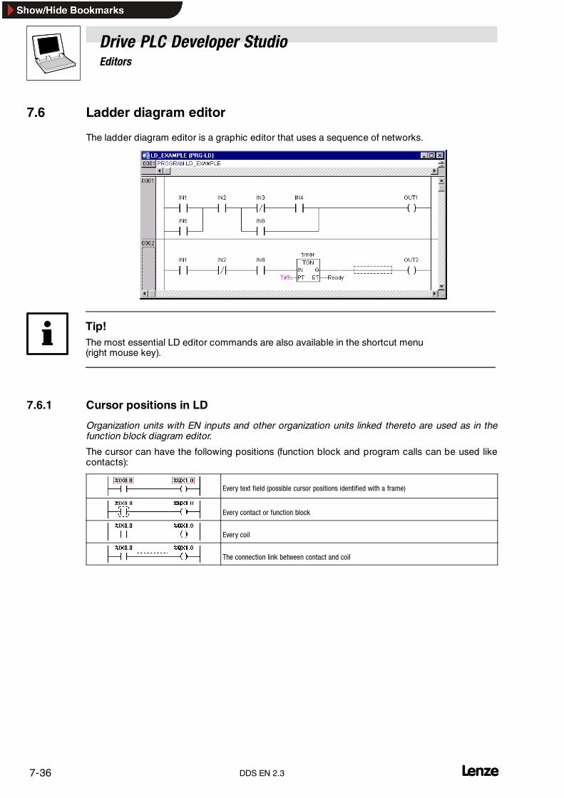
Drive PLC Developer StudioEditors
7-36 lDDS EN 2.3
7.6 Ladder diagram editor
The ladder diagram editor is a graphic editor that uses a sequence of networks.
Tip!The most essential LD editor commands are also available in the shortcut menu(right mouse key).
7.6.1 Cursor positions in LD
Organization units with EN inputs and other organization units linked thereto are used as in thefunction block diagram editor.
The cursor can have the following positions (function block and program calls can be used likecontacts):
Every text field (possible cursor positions identified with a frame)
Every contact or function block
Every coil
The connection link between contact and coil

Drive PLC Developer StudioEditors
7-37l DDS EN 2.3
7.6.2 Commands in the “Insert” menu
7.6.2.1 ContactIcon: Menu: Insert�Contact Keyboard: <Ctrl>+<K>
Use this command to insert a contact in front of the position selected in the network.
• If the selected position is a coil or a connection link between contacts and coil, the newcontact is connected in series to the previous contacts.
The inserted contact is pre-assigned ”???” .
• Click this text to change it to the required constant or variable. Alternatively, use the HelpManager (<F2>) to do so.
7.6.2.2 Parallel contactIcon: Menu: Insert�Parallel contact Keyboard: <Ctrl>+<R>
Use this command to insert a contact in parallel to the position selected in the network.
• If the selected position is a coil or a connection link between contact and coil, the newcontact is connected parallel to the previous contacts.
The inserted contact is pre-assigned ”???” .
• Click this text to change it to the required constant or variable. Alternatively, use the HelpManager ( <F2> ) to do so.
7.6.2.3 CoilIcon: Menu: Insert�Coil Keyboard: <Ctrl>+<L>
Use this command to insert a coil parallel to the already existing coils.
• If the selected position is a connection between contacts and coils, the new coil will be thelast coil.
• If the selected position is a coil, the new coil will be inserted directly above it.
The coil is pre-assigned ”???” .
• Click the text to change it to the required variable. Alternatively, use the Help Manager (<F2>)to do so.
7.6.2.4 Insert at organization unitIcon: - Menu: Insert�Insert at organization unit
�Input�Output�Box�Assignment
Keyboard:<Ctrl>+<U>
<Ctrl>+<A>
This submenu to the Insert menu contains commands to add further elements to an alreadyinserted organization unit with EN input.

Drive PLC Developer StudioEditors
7-38 lDDS EN 2.3
An organization unit with EN may be given the name of a function block so that Insert�Insert atorganization unit can be executed.
In this example, AND was overwritten with the name of timer TP .
• The commands in this submenu can be executed at the same cursor positions as theassociated commands in the FBD.
Input Use Input to add a new input to the organization unit.
Output Use Output to add another assignment to an organization unit output.
Box Use Box to add a new organization unit to the selected one. The output of the new organization unit is connected to theselected input. The organization unit is pre-assigned AND.
Assignment Use Assignment to add an assignment to a variable.
7.6.2.5 JumpIcon: - Menu: Insert�Jump Keyboard: -
Use this command to insert a jump in parallel to the end of the existing coils.
• If the incoming line has a value ”ON” , the jump to the selected label will be carried out.
• The selected position must be the connection between contacts and coils or a coil.
The jump is pre-assigned ”???” .
• Click the text to change it to the required jump label.
7.6.2.6 ReturnIcon: - Menu: Insert �Return Keyboard: -
Use this command to insert a RETURN instruction in parallel to the end of the existing coils.
• If the incoming line has a value ”ON” , processing of the organization unit in this network willbe terminated.
• The selected position must be the connection between contacts and coils or a coil.
7.6.3 Organization units with EN inputs
Should the LD network need to be used to control other organization unit calls, it is necessary toinsert an organization unit with an EN input or an organization unit with a Boolean input.
• An organization unit with EN inputs is connected in parallel to the coils.
• Based on one EN organization unit, the network can be further developed as in FBD.
• The commands for inserting elements at already inserted EN organization units are availablein menu Insert , submenu Insert at organization unit .
Operators, function blocks, programs or a function with EN input respond like the associatedorganization unit in the FBD with the exception that its execution is controlled via the EN input. Thisinput is connected to the connection line between coils and contacts. If this connection transfersthe information ”ON” , the organization unit will be evaluated.
LD as FBD
Once an organization unit with EN input has been created, it will be possible to build up a networkas in FBD. An EN organization unit can receive data from operators, functions and function blocksand also transfer data to such organization units.
Drive PLC Developer StudioEditors
7-39l DDS EN 2.3
In other words, programming of a network in the LD editor as in FBD merely requires prior insertionof an EN operator into a new network before further-developing it as in the FBD editor. A networkdeveloped like this acts like the associated network in FBD.
7.6.3.1 Operator with ENIcon: - Menu: Insert�Operator with EN Keyboard: -
Use this command to insert an operator with EN input.
• The selected position must be the connection between contacts and coils or a coil.
The new operator is inserted in parallel to the coils below the selected one and is always an AND.
• This can be changed to any other operator by selecting and overwriting the text.
• Use the Help Manager ( <F2>) to select the required operator from the list of supportedoperators.
7.6.4 Commands in the “Extras” menu
7.6.4.1 Paste afterIcon: - Menu: Extras�Paste after Keyboard: -
Use this command to paste the contents of the clipboard as serial contact behind the selectedposition.
• This command can only be used if the contents of the clipboard and the selected position arecontact networks.
7.6.4.2 Paste belowIcon: - Menu: Extras�Paste below Keyboard: <Ctrl>+<U>
Use this command to paste the contents of the clipboard as parallel contact below the selectedposition.
• This command can only be used if the contents of the clipboard and the selected position arecontact networks.
7.6.4.3 Paste aboveIcon: - Menu: Extras�Paste above Keyboard: -
Use this command to paste the contents of the clipboard as parallel contact above the selectedposition.
• This command can only be used if the contents of the clipboard and the selected position arecontact networks.
7.6.4.4 NegationIcon: Menu: Extras �Negation Keyboard: <Ctrl>+<N>
Use this command to negate a contact, coil, jump/RETURN instruction or an input or output of an ENorganization unit at the current cursor position.
• A slash appears between the parentheses of a coil or the straight lines of a contact: (/) or |/|
• As in the FBD editor, jumps, returns, inputs and outputs of EN organization units are identifiedwith a small circle in the connection.
The coil now writes the negated value of the input connection to the associated Boolean variable.
• A negated contact switches the status of the input to the output exactly when the associatedBoolean variable returns the value FALSE .
• If a jump or return is highlighted, the input of the jump or return will be negated.
A negation can be deleted by another negation.

Drive PLC Developer StudioEditors
7-40 lDDS EN 2.3
7.6.4.5 Set/ResetIcon: - Menu: Extras �Set/Reset Keyboard: -
Use this command to define coils as Set or Reset coils.
A Set coil is identified with an ”S” in the coil symbol.
If the network result is TRUE , the Boolean variable, as a consequence of the Set coil, will be setto TRUE . Otherwise, the variable will remain as it is.
If the network result is TRUE , the Boolean variable, as a consequence of the Set coil, will be setto TRUE . Otherwise, the variable will remain as it is.
A Reset coil never overwrites the value FALSE in the associated Boolean variable.
• A Reset coil is identified with an ”R” in the coil symbol.
If the network result is TRUE , the Boolean variable, as a consequence of the Reset coil, will be setto FALSE. . Otherwise, the variable will remain as it is.
If the command is executed more than once, the coil toggles between Set, Reset and normal coil.
7.6.4.6 Open instance
This command corresponds to the command Project�Open instance.
7.6.4.7 OptionsIcon: - Menu: Extras �Options Keyboard: -
Use this command to open the dialog box Function block and ladder diagram options .
Completing the input fields as illustrated will update the associated contact with the followingcomment field.
Use the input fields Minimum comment size and Maximum comment size to enter a commenton the current contact or the current coil.
If check box Comments per contact is active, the input fields Lines for variable comment canbe used to input a variable-specific comment, and Lines for variable text to specify a variablename.
If check box Networks with line breaks is active, the network will break depending on the windowsize.

Drive PLC Developer StudioEditors
7-41l DDS EN 2.3
7.6.5 The LD in online mode
• In online mode, all contacts and coils in ON status (TRUE) are marked blue in the LD.
• In online mode, all lines in TRUE status are marked blue in the LD.
• The values of the associated variables are displayed at function block inputs and outputs.
• Breakpoints can only be set to networks. In single-stepping mode, the process jumps toevery single network one after the other.
• On active flow control, the number fields of the processed networks will be marked green.
Tip!Positioning themouse pointer briefly over a variablewill display a tool tip with the variable’s address,type and any comments.

Drive PLC Developer StudioEditors
7-42 lDDS EN 2.3
7.7 CFC editor
Note!If the error message
Internal error...: A CFC in this project is corrupted, and got restored. Please check its logics
should occur when the project is stored please proceed as follows:
• Do not delete the error message.
• Save an existing backup copy (automatic saving, last version) under another name.The automatically saved backup copy has the suffix *.asd and is saved in the same folder asthe *.pro file.
• After that, confirm the error messageDDS tries to correct the error automatically.
• Check the logic of the CFC editor.
• If errors are found use the backup copy. Delete the *.pro file and change the *.asd file into*.pro.
This measure ensures that you always have a reliable and up-to-date project version.
The CFC editor (Continuous Function Chart editor) does not use any networks. Instead, elementsmay be placed freely.
Note!If you work with the CFC editor, the automatic backup should be active.
Project�Option Category Load & Save.
After extensions or changes the operations should be saved.
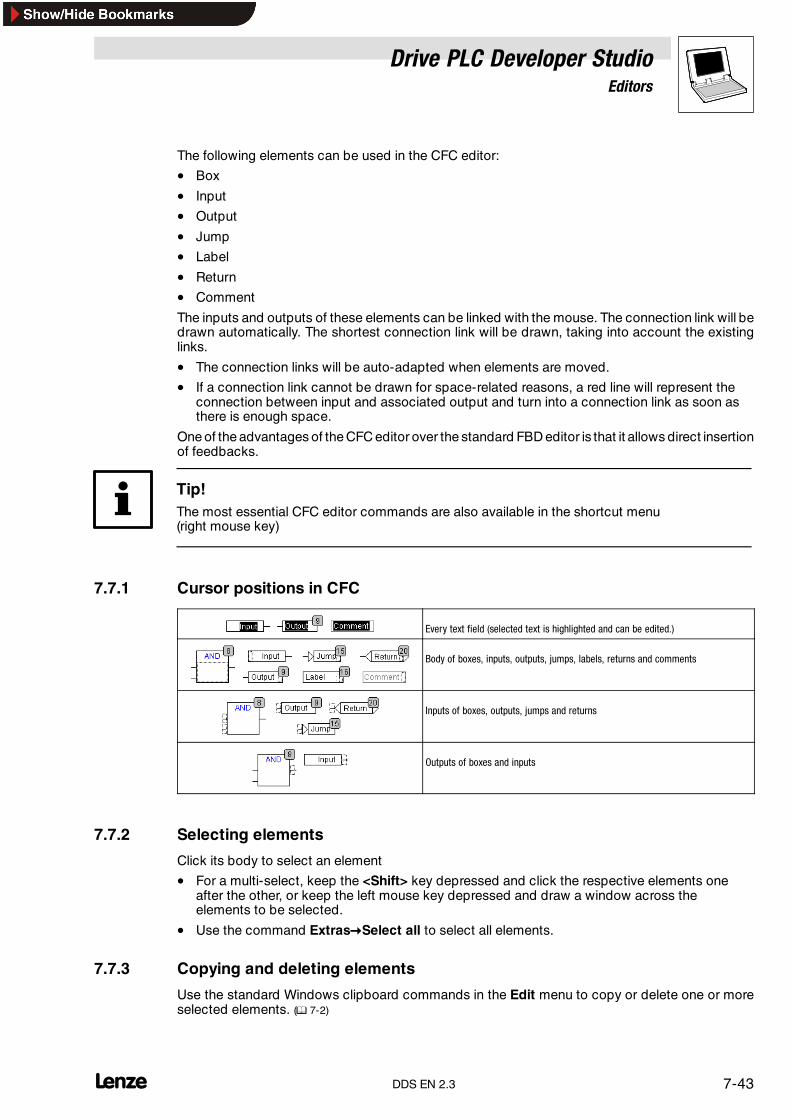
Drive PLC Developer StudioEditors
7-43l DDS EN 2.3
The following elements can be used in the CFC editor:
• Box
• Input
• Output
• Jump
• Label
• Return
• Comment
The inputs and outputs of these elements can be linked with the mouse. The connection link will bedrawn automatically. The shortest connection link will be drawn, taking into account the existinglinks.
• The connection links will be auto-adapted when elements are moved.
• If a connection link cannot be drawn for space-related reasons, a red line will represent theconnection between input and associated output and turn into a connection link as soon asthere is enough space.
One of the advantages of the CFC editor over the standard FBD editor is that it allows direct insertionof feedbacks.
Tip!The most essential CFC editor commands are also available in the shortcut menu(right mouse key)
7.7.1 Cursor positions in CFC
Every text field (selected text is highlighted and can be edited.)
Body of boxes, inputs, outputs, jumps, labels, returns and comments
Inputs of boxes, outputs, jumps and returns
Outputs of boxes and inputs
7.7.2 Selecting elements
Click its body to select an element
• For a multi-select, keep the <Shift> key depressed and click the respective elements oneafter the other, or keep the left mouse key depressed and draw a window across theelements to be selected.
• Use the command Extras�Select all to select all elements.
7.7.3 Copying and deleting elements
Use the standard Windows clipboard commands in the Edit menu to copy or delete one or moreselected elements. (� 7-2)
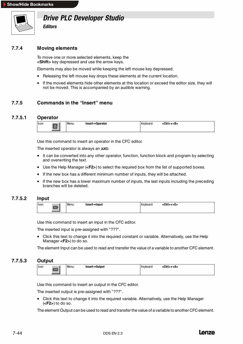
Drive PLC Developer StudioEditors
7-44 lDDS EN 2.3
7.7.4 Moving elements
To move one or more selected elements, keep the<Shift> key depressed and use the arrow keys.
Elements may also be moved while keeping the left mouse key depressed.
• Releasing the left mouse key drops these elements at the current location.
• If the moved elements hide other elements at this location or exceed the editor size, they willnot be moved. This is accompanied by an audible warning.
7.7.5 Commands in the “Insert” menu
7.7.5.1 OperatorIcon: Menu: Insert�Operator Keyboard: <Ctrl>+<B>
Use this command to insert an operator in the CFC editor.
The inserted operator is always an AND.
• It can be converted into any other operator, function, function block and program by selectingand overwriting the text.
• Use the Help Manager (<F2>) to select the required box from the list of supported boxes.
• If the new box has a different minimum number of inputs, they will be attached.
• If the new box has a lower maximum number of inputs, the last inputs including the precedingbranches will be deleted.
7.7.5.2 InputIcon: Menu: Insert�Input Keyboard: <Ctrl>+<E>
Use this command to insert an input in the CFC editor.
The inserted input is pre-assigned with ”???” .
• Click this text to change it into the required constant or variable. Alternatively, use the HelpManager <F2>) to do so.
The element Input can be used to read and transfer the value of a variable to another CFC element.
7.7.5.3 OutputIcon: Menu: Insert�Output Keyboard: <Ctrl>+<A>
Use this command to insert an output in the CFC editor.
The inserted output is pre-assigned with ”???” .
• Click this text to change it into the required variable. Alternatively, use the Help Manager(<F2>) to do so.
The element Output can be used to read and transfer the value of a variable to another CFCelement.

Drive PLC Developer StudioEditors
7-45l DDS EN 2.3
7.7.5.4 JumpIcon: Menu: Insert�Jump Keyboard: <Ctrl>+<J>
Use this command to insert a jump in the CFC editor.
The inserted jump is pre-assigned with the text ”???” .
• Click this text to change it into the required jump label to be jumped to.
• Insert a jump label with Insert�Label.
7.7.5.5 LabelIcon: Menu: Insert�Label Keyboard: <Ctrl>+<L>
Use this command to insert a jump label in the CFC editor.
• Click this text to change it into the required jump label.
• Insert a jump to this label using Insert�Jump.
7.7.5.6 ReturnIcon: Menu: Insert�Return Keyboard: <Ctrl>+<R>
Use this command to insert a RETURN instruction in the CFC editor.
7.7.5.7 CommentIcon: Menu: Insert�Comment Keyboard: <Ctrl>+<K>
Use this command to insert a comment in the CFC editor.
• Use <Ctrl>+<Enter> to add a line break in a comment.
7.7.5.8 Box inputIcon: - Menu: Insert�Box input Keyboard: <Ctrl>+<U>
Use this command to insert a box input in the CFC editor.
Withmany operators thenumber of inputs may vary (e. g. the box ADD may have two or more inputs).
• In order to extend such an operator by one input, the operator itself must be selected first.
7.7.5.9 In pin / out pinIcon: Menu: Insert�In pin Keyboard: -
Icon: Menu: Insert�Out pin Keyboard: -
These commands are available only while a macro is open and
• support the insertion of in or out pins as the inputs and outputs of a macro.
• receive no position index.
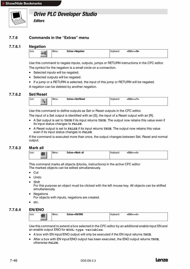
Drive PLC Developer StudioEditors
7-46 lDDS EN 2.3
7.7.6 Commands in the “Extras” menu
7.7.6.1 NegationIcon: Menu: Extras�Negation Keyboard: <Ctrl>+<N>
Use this command to negate inputs, outputs, jumps or RETURN instructions in the CFC editor.
The symbol for the negation is a small circle on a connection.
• Selected inputs will be negated.
• Selected outputs will be negated.
• If a jump or a RETURN is selected, the input of this jump or RETURN will be negated.
A negation can be deleted by another negation.
7.7.6.2 Set/ResetIcon: Menu: Extras�Set/Reset Keyboard: <Ctrl>+<T>
Use this command to define outputs as Set or Reset outputs in the CFC editor.
The input of a Set output is identified with an [S], the input of a Reset output with an [R].
• A Set output is set to TRUE if its input returns TRUE. The output now retains this value even ifits input status changes to FALSE.
• A Reset output is set to FALSE if its input returns TRUE. The output now retains this valueeven if its input status changes to FALSE.
If the command is executed more than once, the output changes between Set, Reset and normaloutput.
7.7.6.3 Mark allIcon: Menu: Extras�Mark all Keyboard: <Ctrl>+<I>
This command marks all objects (blocks, instructions) in the active CFC editorThe marked objects can be edited simultaneously.
• Cut
• Undo
• ShiftFor this purpose an object must be clicked with the left mouse key. All objects can be shiftedsimultaneously.
• NegationsFor objects with inputs, negations are created.
• etc.
7.7.6.4 EN/ENOIcon: Menu: Extras�EN/ENO Keyboard: <Ctrl>+<I>
Use this command to extend a box selected in the CFC editor by an additional enable input EN andan enable output ENO for BOOL-type variables.
• A box with EN input/ENO output will only be executed if the EN input returns TRUE.
• After a box with EN input/ENO output has been executed, the ENO output returns TRUE,otherwise FALSE.
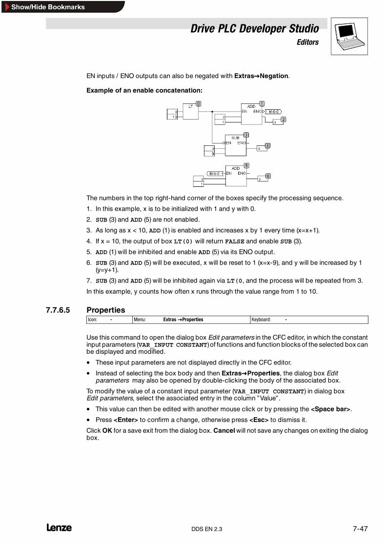
Drive PLC Developer StudioEditors
7-47l DDS EN 2.3
EN inputs / ENO outputs can also be negated with Extras�Negation.
Example of an enable concatenation:
The numbers in the top right-hand corner of the boxes specify the processing sequence.
1. In this example, x is to be initialized with 1 and y with 0.
2. SUB (3) and ADD (5) are not enabled.
3. As long as x < 10, ADD (1) is enabled and increases x by 1 every time (x=x+1).
4. If x = 10, the output of box LT(0) will return FALSE and enable SUB (3).
5. ADD (1) will be inhibited and enable ADD (5) via its ENO output.
6. SUB (3) and ADD (5) will be executed, x will be reset to 1 (x=x-9), and y will be increased by 1(y=y+1).
7. SUB (3) and ADD (5) will be inhibited again via LT(0, and the process will be repeated from 3.
In this example, y counts how often x runs through the value range from 1 to 10.
7.7.6.5 PropertiesIcon: - Menu: Extras �Properties Keyboard: -
Use this command to open the dialog box Edit parameters in the CFC editor, in which the constantinput parameters (VAR_INPUT CONSTANT)of functions and function blocks of the selected box canbe displayed and modified.
• These input parameters are not displayed directly in the CFC editor.
• Instead of selecting the box body and then Extras�Properties, the dialog box Editparameters may also be opened by double-clicking the body of the associated box.
To modify the value of a constant input parameter (VAR_INPUT CONSTANT) in dialog boxEdit parameters, select the associated entry in the column ”Value” .
• This value can then be edited with another mouse click or by pressing the <Space bar>.
• Press <Enter> to confirm a change, otherwise press <Esc> to dismiss it.
Click OK for a save exit from the dialog box. Cancel will not save any changes on exiting the dialogbox.

Drive PLC Developer StudioEditors
7-48 lDDS EN 2.3
7.7.6.6 ConnectorIcon: - Menu: Extras �Connector Keyboard: -
Use this command to connect elements viaconnectors in the CFCeditor instead of connection links.
• Output and associated input are identified with a uniquely named connector.
• The name of the connector is automatically assigned by the program, but can be changed.
Where two elements are already linked by a connection that is now to be changed into a link withconnectors, first select the output where the connection starts and then Extras�Connector.
Before command execution: After command execution:
Tip!Connections via connectors can be changed back into normal links by selecting the output of theconnection and executing the command Extras�Connector again.
Changing the name of a connector
Note that the name of the connector is a feature of the output of a connection and will be savedtogether with it.
Editing a connector at an input:
• If the text in the connector is changed, the new name will be accepted for all associatedconnectors at inputs.
• The text cannot be changed into a name that already belongs to another connector. Thename must be unique.
Editing a connector at an output:
• A change to the text in the connector will also be reflected in the associated connector at theother box.
7.7.7 Creating connections
Inputs and outputs of elements can be connected by drawing a connection established throughkeeping the left mouse key depressed.
• An element input can be connected to exactly one element output.
• An element output can be connected to several element inputs.
There are several possibilities to connect the input of element E2 to the output of element E1:
1. Left-click the output of element E1, keep the left mouse key depressed, drag the mouse pointer tothe input of element E2, and then release the left mouse key.– Dragging the mouse creates a connection between the output of element E1 and the mousepointer.
2. Left-click the input of element E2, keep the left mouse key depressed, drag the mouse pointer to theoutput of element E1, and release the left mouse key.

Drive PLC Developer StudioEditors
7-49l DDS EN 2.3
3. Move either E1 or E2 until the output of element E1 touches the input of element E2.
4. If element E2 is a box with an unassigned input, the mouse pointer can also create a connectionbetween an output of E1 and the body of E2.– Releasing the left mouse key automatically creates a connection with the topmost unassigned inputof E2.
– If the box E2 has no unassigned input but is an operator that can be extended by one input, a newinput will be created automatically.
Use method 1, 2 or 4 to connect the output and input of a box (feedback).
Connecting two pins
– Left-click a pin and keep the key depressed.– Drag the mouse to the required pin, and release the mouse key.
Tip!Make sure not to accidentally leave the editor window during dragging as this will lead to screenscrolling.
Simple data types are type-checked during connection. Incompatible types cannot be connected.
7.7.8 Changing connections
A connection between the output of E1 and the input of E2 can be easily changed into aconnection between the output of E1 and the input of E3.
Click on the E2 input and keep the left mouse key depressed while moving the mouse pointer from inputE2 towards input E3.
7.7.9 Deleting connections
There are several possibilities to deletea connectionbetween theoutput of element E1and the inputof element E2.
• Select the output of E1 and press <Del>, or execute command Edit�Delete. If the E1 outputis connected to several inputs, several connections will be deleted.
• Select the input of E2 and press <Del>, or execute command Edit�Delete.
• Select the E2 input, keep the left mouse key depressed and follow the connection away frominput E2. Release the mouse key in a free area to delete the connection.

Drive PLC Developer StudioEditors
7-50 lDDS EN 2.3
7.7.10 Feedbacks
Contrary to the standard function block diagram editor, the CFC editor can display feedbacksdirectly.
Note that an internal intermediate variable will be generally created for the output of a box.
• With operators the data type of the intermediate variable depends on the highest-order datatype of the inputs.
• With constants the data type depends on the lowest possible data type, i.e. data type SINTis assumed for constant ’1’.
If an addition is carried out with feedback and constant ’1’, the first input returns data type SINT,whereas the second input remains undefined as a consequence of the feedback. Thus also theintermediate variable is SINT-type. Only then will the value of the intermediate variable beassigned to the output variable.
The illustration below shows an addition with feedback and an addition directly with a variable.Variables x and y are to be INT-type in this case:
Addition with feedback: Addition directly with a variable:
The two additions differ as follows:
• Variable y can be initialized with a nonzero value, whereas the intermediate variable of anaddition with feedback needs a zero.
• The intermediate variable of the addition with feedback is SINT-type, that of the additionwith variable y of INT-type.
• Variables x and y have different values from call 128. Although INT-type, variable x isassigned value –128 as the intermediate variable has overflown. Variable y is assigned value128.
7.7.11 Processing sequence
The CFC editor assigns a processing number to boxes, outputs, jumps, returns and labels andprocesses the individual elements in this sequence at runtime.
• On element insertion, this number will be automatically assigned in a topological sequence(from left to right and from top to bottom).
• If the sequence has already been changed, the new element will be assigned the number ofits topological descendant, and all higher numbers will be increased by one.
• Moving an element will not affect the number.
• The sequence influences the result and must therefore be changed under certaincircumstances.
• If sequence display is activated, the element’s processing number is displayed in a grey fieldin the top right-hand corner.
Processing sequence display on: Processing sequence display off:

Drive PLC Developer StudioEditors
7-51l DDS EN 2.3
7.7.12 Commands in the “Extras” menu, submenu “Order”
7.7.12.1 DisplayIcon: - Menu: Extras�Order�Display Keyboard: -
Use this command to switch the processing sequence display on and off in the CFC editor.
• The default is ON.
• A tick in front of the menu command indicates that the display is on.
7.7.12.2 Arrange topologicallyIcon: - Menu: Extras �Order
�Arrange topologicallyKeyboard: -
Use this command to arrange the selected elements in topological sequence in the CFC editor.
Elements are arranged in topological sequence if they are processed from left to right and from topto bottom, i.e. with topologically arranged elements, the number increases from left to right and fromtop to bottom. Only the element position is relevant in this case, not the connections.
Procedure
1. All selected elements are taken out of the sequential function chart.
2. The residual sequential function chart is updated to reflect consistent numbering.
3. The selected elements are then reinserted individually into the residual sequential functionchart from bottom right to top left.
4. Every selected element is inserted into the sequential function chart with the sequencenumber of the topological descendant, increasing the sequence numbers of all topologicaldescendants by one.
Program example
Elements E1, E2 and E3 are to be arranged topologically.
All selected elements are removed from the sequential function chart. The residual sequentialfunction chart is then updated to reflect consistent numbering.
The selected elements are then reinserted into the residual sequential function chart individuallyfrom bottom right to top left.
Element E3 will be inserted first with the sequence number of the topological descendant (E5),increasing the sequence numbers of all topological descendants (E5, E6) by 1.
Element E2 will be inserted with the sequence number of the topological descendant (E6),increasing the sequence numbers of all topological descendants (E6) by 1.

Drive PLC Developer StudioEditors
7-52 lDDS EN 2.3
Element E1 will be inserted with the sequence number of the topological descendant (E2),increasing the sequence numbers of all topological descendants (E2, E6) by 1.
After command execution, the sample sequential function chart will look like this.
7.7.12.3 Arrange in accordance with the data flowIcon: - Menu: Extras �Order
�Arrange in accordance with the dataflow
Keyboard: -
Use this command to arrange all elements in accordance with their data flow in the CFC editor.
• This command is applied to all elements.
• The processing sequence is determined by the data flow of the elements, not by theirposition.
Before command execution: After command execution:
7.7.12.4 Bring forward by oneIcon: - Menu: Extras�Order�Bring forward by one Keyboard: -
Use this command to bring all selected elements forward by one position within the sequentialfunction chart in the CFC editor.
• This does not apply for the elements at the beginning of the sequential function chart.
7.7.12.5 Send back by oneIcon: - Menu: Extras�Order�Send back by one Keyboard: -
Use this command to send all selected elements back by one position within the sequential functionchart in the CFC editor.
• This does not apply for the elements at the end of the sequential function chart.

Drive PLC Developer StudioEditors
7-53l DDS EN 2.3
7.7.12.6 To the beginningIcon: - Menu: Extras�Order�To the beginning Keyboard: -
Use this command to bring all selected elements to the beginning of the sequential function chartin the CFC editor.
• The sequence among the selected elements remains unchanged.
• The sequence among the other elements also remains unchanged.
7.7.12.7 To the endIcon: - Menu: Extras�Order�To the end Keyboard: -
Use this command to send all selected elements to the end of the sequential function chart in theCFC editor.
• The sequence among the selected elements remains unchanged.
• The sequence among the other elements also remains unchanged.
7.7.12.8 Create macroIcon: Menu: Extras�Create Macro Keyboard: <Ctrl>+<I>
Use this command to group several boxes into one block that can then be named as a macro.
• Macros are duplicated with Copy and Insert. Each copy represents a separate macro thatcan be freely named. Macros are no references.
• Connections separated by macros create in or out pins at the macro. Connections to inputscreate an in pin, for example. The default name appears in the format In-<n> next to thecreated in pin, and as Out-<n> for outputs.
• Any connections affected that featured connectors prior to macro creation, are assigned theconnector the macro PIN.
• Initially, any macro is given the default name MACRO. That can be changed.
Three boxes and one input have been selected for the example.
The following macro is created withmenu command Extras�Create macro. The unit can beshownmore efficiently by moving the boxes.

Drive PLC Developer StudioEditors
7-54 lDDS EN 2.3
7.7.12.9 Step into macroIcon: - Menu: Extras�Step into macro Keyboard: -
Use this menu command or double-click the macro body to open the macro for processing in theeditor window.
• The created pin boxes can be edited like normal boxes, differing in the representation andcontaining no position index.
• Pin boxes have rounded edges. The pin box text matches the name of the pin in the macrorepresentation.
• The sequence of pins at the macro box is dependent on the macro element processingsequence.– Low-before-high sequence index– Top-before-bottom pin
• The processing sequence in the macro is a self-contained procedure. In its higher-level box,the macro is treated as a block. Commands are effective in the macro only.
7.7.12.10 Expand macroIcon: - Menu: Extras�Expand macro Keyboard: -
Use this menu command to re-expand the selected macro into its individual elements.
• Connections to in / out pins are represented by element inputs / outputs.
• The unit is moved automatically in cases where the editor does not offer sufficient space forexpansion.
• The elements can be returned to efficient positions following expansion.
Note!All macros are expanded if the project is converted into another language.
7.7.12.11 One Macro Level BackIcon: Menu: Extras�One Makro Level Back Keyboard: -
This command is active when jumping to a macro or the macro is open for processing.
With interleaved macros it is possible to jump back one macrolevel.

Drive PLC Developer StudioEditors
7-55l DDS EN 2.3
7.7.12.12 All Macro Levels BackIcon: Menu: Extras�All Makro Levels Back Keyboard: -
This command is active when jumping to a macro or the macro is open for processing.
With interleaved macros it is possible to jump back all macrolevels.
7.7.12.13 Open instanceIcon: - Menu: Extras�Open instance Keyboard: -
This command is identical to menu item Project�Open instance.
7.7.12.14 ZoomIcon: - Menu: Extras�Zoom Keyboard: <Alt>+<Enter>
Use this command to open the implementation of a selected box.
7.7.13 CFC in online mode
Monitoring
The values for inputs and outputs are displayed within the input or output boxes. Constants are notmonitored (visible). For non-Boolean variables, the boxes will be enlarged in accordance with thedisplayed values. If the value is TRUE, variable names and connection in Boolean connections arehighlighted in blue.
Internal Boolean connections are also highlighted in blue in online mode.
Breakpoints
Breakpoints may be set to all elements with a sequential function chart index. Program processingwill be halted prior to execution of the respective element. The element’s sequential function chartindex will be used as the breakpoint position during the breakpoint dialog.
Set breakpoints to a selected element via– F9– Online�Breakpoint on/off– the CFC editor shortcut menu
Following repeated execution of menucommand Online�Breakpoint on/off thebreakpoint will bedeleted again. The breakpoint can be toggled by double-clicking the element.
Breakpoints are represented under Project�Options Category Colours.
Return label
In online mode, a jump labelwith the identifier RETURNis automatically generated in the first columnand after the last element in the CFC editor. This label marks the box end and is jumped to duringsingle-stepping prior to exiting the box. No RETURN labels are inserted in macros.
Single-stepping
If the menu command Online�Single step over is active, the process will always jump to theelement with the higher sequential function chart index.
If the menu command Online�Single step in is active, the process will branch into theimplementation in the case of a macro or an organization unit.

Drive PLC Developer StudioEditors
7-56 lDDS EN 2.3
7.8 SFC editor
The graphic Sequential Function Chart editor describes the chronological sequence of variousactions within a program.
Tip!The most essential commands for the SFC editor are also available in the shortcut menu(right mouse key)Tool tips display the full names of transitions, actions, etc.
7.8.1 Selecting blocks
A selected block is a set of SFC elements surrounded by a dotted rectangle.
• Elements (steps, transitions, jumps) can be selected with a click or the arrow keys.
• To select a set of several elements, select one and press the <Shift> key before selecting theelement in the left- or right-hand bottom corner of the set. The resulting set is the smallestcontiguous set of elements containing these two elements.
Tip!Note that all commands must comply with the language conventions to be executed.

Drive PLC Developer StudioEditors
7-57l DDS EN 2.3
7.8.2 Commands in the “Insert” menu
7.8.2.1 Step transition (before)Icon: Menu: Insert�Step transition (before) Keyboard: <Ctrl>+<T>
Use this command to insert a step followed by a transition before the block selected in the SFCeditor.
Tip!A step followed by a transition can be deleted by selecting step and transition and pressing the<Del> key.(Keep the <Ctrl> key depressed to select several objects.)
7.8.2.2 Step transition (after)Icon: Menu: Insert�Step transition (after) Keyboard: <Ctrl>+<E>
Use this command to insert a step followed by a transition after the first transition in the blockselected in the SFC editor.
Tip!A step followed by a transition can be deleted by selecting step and transition and pressing the<Del> key.(Keep the <Ctrl> key depressed to select several objects.)
7.8.2.3 Alternative branch (right)Icon: Menu: Insert�Alternative branch (right) Keyboard: <Ctrl>+<A>
Use this command to insert an alternative branch as right-oriented branch to the block selected inthe SFC editor.
• For this purpose, the selected block must start and end with a transition. The new branchthen consists of a transition.
7.8.2.4 Alternative branch (left)Icon: Menu: Insert�Alternative branch (left) Keyboard: -
Use this command to insert an alternative branch as left-oriented branch to the block selected inthe SFC editor.
• For this purpose, the selected block must start and end with a transition. The new branchthen consists of a transition.

Drive PLC Developer StudioEditors
7-58 lDDS EN 2.3
7.8.2.5 Parallel branch (right)Icon: Menu: Insert�Parallel branch (right) Keyboard: <Ctrl>+<L>
Use this command to insert a parallel branch as right-oriented branch to the block selected in theSFC editor.
• For this purpose, the selected block must start and end with a step. The new branch thenconsists of a step.
• To enable jumps to the created parallel branch it must have a jump label.
7.8.2.6 Parallel branch (left)Icon: Menu: Insert�Parallel branch (left) Keyboard: -
Use this command to insert a parallel branch as left-oriented branch to theblock selected in theSFCeditor.
• For this purpose, the selected block must start and end with a step. The new branch thenconsists of a step.
• To enable jumps to the created parallel branch it must have a jump label.
7.8.2.7 JumpIcon: Menu: Insert�Jump Keyboard: <Ctrl>+<U>
Use this command to insert a jump at the end of the branch of the block selected in the SFC editor.
• For this purpose, the branch must be an alternative branch.
• The jump label Step must be substituted with the name of the destination step.
7.8.2.8 Transition jumpIcon: Menu: Insert�Transition jump Keyboard: -
Use this command to insert a transition followed by a jump at the end of the branch selected in theSFC editor.
• For this purpose, the branch must be a parallel branch.
• The jump label Step must be substituted with the name of the destination step.
7.8.2.9 Add entry actionIcon: - Menu: Insert�Add entry action Keyboard: -
Use this command to add an entry action to a step.
• An entry action is executed once-only immediately after the step has been activated.
• The entry action can be implemented in any language.
• A step with entry action is identified with an ”E” in the bottom left-hand corner.

Drive PLC Developer StudioEditors
7-59l DDS EN 2.3
7.8.2.10 Add exit actionIcon: - Menu: Insert�Add exit action Keyboard: -
Use this command to add an exit action to a step.
• An exit action is executed once-only before the step is deactivated.
• The exit action can be implemented in any language.
• A step with exit action is identified with an ”X” in the bottom right-hand corner.
7.8.3 Commands in the “Extras” menu
7.8.3.1 Insert parallel branch (right)Icon: - Menu: Extras�Insert parallel branch (right) Keyboard: -
Use this command to insert the contents of the clipboard as right-oriented parallel branch of theselected block.
• For this purpose, the selected block must start and end with a step.
• The contents of the clipboard must also be an SFC block starting and ending with a step.
7.8.3.2 Add label to parallel branchIcon: - Menu: Extras�Add label to parallel branch Keyboard: -
Where an inserted parallel branch is to be given a jump label, the transition directly before theinserted parallel branch must be selected.
• Execute menu command Extras�Add label to parallel branch .
• The name Parallel 1, 2 etc. is assigned and can be edited. In the example the name isGR_1_2.
• Delete a jump label by deleting the jump label text.
7.8.3.3 Insert afterIcon: - Menu: Extras�Insert after Keyboard: -
Use this command to insert the SFC block in the clipboard after the first step or the first transitionof the selected block (a normal ”Copy” inserts it in front of the selected block).
• The command will be executed only if the resulting SFC structure complies with the languageconventions.

Drive PLC Developer StudioEditors
7-60 lDDS EN 2.3
7.8.3.4 Zoom action/transitionIcon: - Menu: Extras�Zoom action/transition Keyboard: <Alt>+<Enter>
Shortcut: <Alt>+<Enter>
The action of the first step of the selected block or the transition body of the first transition of theselected block will be loaded into the editor in the language it was written in.
• If the action or the transition body is empty, select the language it is to be written in.
7.8.3.5 Delete action/transitionIcon: - Menu: Extras�Delete action/transition Keyboard: -
Use this command to delete the actions of the first step of the selected block or the transition bodyof the first transition of the selected block.
• If either the action, entry action or exit action of a step is implemented, it will be deleted withthis command. Otherwise, a dialog box will appear to select the action or actions to bedeleted.
• If the cursor is in an IEC step action, only this association will be deleted.
• If an IEC step with an associated action has been selected, the association will be deleted. IFthe IEC step has several actions, select an action from the dialog box.
7.8.3.6 Step attributesIcon: - Menu: Extras�Step attributes Keyboard: -
Use this command to open a dialog box for the editing of attributes for the selected step.
Three different entries are possible:
• Use the input field Minimum time to specify the minimum time for processing this step. (TypeTIME)Note: Even if the subsequent transition is TRUE , the step will remain active for this time.
• Use the input field Maximum time to enter the maximum time for processing this step. (TypeTIME)
• Use the input field Comment to enter a comment for the step.
Use Extras����Options to set the SFC editor to display comments or time settings for your steps. Thecomment or time setting will then be displayed to the right of the step.
Tip!SFC flags will be set to signal that the maximum time has been exceeded. These flags can beinterrogated by the user.
The time the step has already been active is displayed in online mode.

Drive PLC Developer StudioEditors
7-61l DDS EN 2.3
The following example shows a step whose processing is to take a minimum of two and a maximumof ten seconds.
7.8.3.7 Time limit overviewIcon: - Menu: Extras�Time limit overview Keyboard: -
Use this command to open the dialog box Time limit overview to edit the time settings for your SFCsteps.
The dialog box Time limit overview displays all steps of your SFC organization unit.
If a time limit has been entered for a step, it will be shown to the right of the step (minimum limit first,then maximum limit).
Edit time limits
Time limits can be edited:
1. Click the required step in the overview. The step name is displayed at the bottom of thewindow.
2. Use input fields Minimal time / Maximal time to specify the required time limit (constant orvariable of type TIME), e. g. T#3s.
3. Click OK to close the dialog box and save the changes.
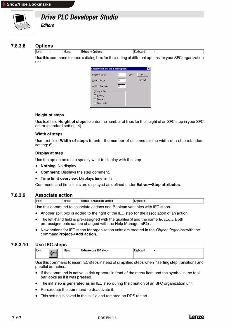
Drive PLC Developer StudioEditors
7-62 lDDS EN 2.3
7.8.3.8 OptionsIcon: - Menu: Extras �Options Keyboard: -
Use this command to open a dialog box for the setting of different options for your SFC organizationunit.
Height of steps
Use text field Height of steps to enter the number of lines for the height of an SFC step in your SFCeditor (standard setting: 4).
Width of steps
Use text field Width of steps to enter the number of columns for the width of a step (standardsetting: 6)
Display at step
Use the option boxes to specify what to display with the step.
• Nothing: No display.
• Comment: Displays the step comment.
• Time limit overview: Displays time limits.
Comments and time limits are displayed as defined under Extras����Step attributes.
7.8.3.9 Associate actionIcon: - Menu: Extras �Associate action Keyboard: -
Use this command to associate actions and Boolean variables with IEC steps.
• Another split box is added to the right of the IEC step for the association of an action.
• The left-hand field is pre-assigned with the qualifier N and the name Action. Bothpre-assignments can be changed with the Help Manager <F2>.
• New actions for IEC steps for organization units are created in the Object Organizer with thecommandProject����Add action.
7.8.3.10 Use IEC stepsIcon: Menu: Extras�Use IEC steps Keyboard: -
Use this command to insert IEC steps instead of simplified steps when inserting step transitions andparallel branches.
• If the command is active, a tick appears in front of the menu item and the symbol in the toolbar looks as if it was pressed.
• The init step is generated as an IEC step during the creation of an SFC organization unit.
• Re-execute the command to deactivate it.
• This setting is saved in the ini file and restored on DDS restart.

Drive PLC Developer StudioEditors
7-63l DDS EN 2.3
7.8.4 Commands in the “Project” menu
7.8.4.1 Add actionIcon: - Menu: Project �Add action Keyboard: -
Use this command to generate an action for the selected SFC organization unit in theObjectOrganizer, that can be used for the IEC steps of this organization unit.
• Select the action name and the language to be used to implement the action from the dialogbox displayed after command selection.
The new action will be added under its SFC organization unit in theObject Organizer,. and a plus signwill appear in front of the SFC organization unit.
• Click the plus sign to display all action objects. A minus sign will appear in front of theorganization unit.
• Click the minus sign to hide the actions again and to return the plus sign.
Tip!The shortcut menu commandsExpand node and Minimize node can also be used to display orhide the objects.
Double-clicking the action or pressing <Enter> loads the action into the editor.
7.8.5 SFC flags
So called SFC flags will be set if a step in SFC is active longer than specified in its attributes.
The user can define more variables to control the sequential function chart.
Before SFC flags can be used they must be declared. The declaration may be global or local, asoutput or input variable.
SFCEnableLimit
• Variable is of type BOOL.
• If this variable is TRUE , step timeouts will be registered inSFCError. Otherwise, timeouts willbe ignored.
SFCInit
• Variable of type BOOL.
• If this variable is TRUE , the SFC will be reset to the init step and the other SFC flags will bereset, too. The init step remains active but will not be executed as long as the variable isTRUE . Only if SFCInit is reset to FALSE will the organization unit be processed normallyagain.
SFCReset
This BOOL -type variable behaves similarly to SFCInit. Here, however, init step processing iscontinued after initialization. This aspect can be used to reset the SFCReset flag in the init stepimmediately to FALSE.
Tip!SFCInit and SFCReset cannot be used simultaneously in one organization unit. SFCInit willalways have priority.

Drive PLC Developer StudioEditors
7-64 lDDS EN 2.3
Example of a declaration
PROGRAM flagsVARSFCEnableLinit:BOOL;SFCError:BOOL;SFCErrorStep:STRING;SFCReset AT %IX1.0.2: BOOL;SFCInit AT %IX1.0.3:BOOL;END_VAR
SFCQuitError
Variable of type BOOL.
Processing of the SFC diagram will be suspended as long as this variable is TRUE , resetting apotential timeout in variable SFCError . Resetting the variable to FALSEwill reset all previous timesin the active steps.
SFCPause
• Variable of type BOOL.
• Processing of the SFC diagram will be suspended as long as this variable is TRUE .
SFCTrans
• Variable of type BOOL.
• This variable is set to TRUE if a transition becomes TRUE.
SFCError
• Variable of type BOOL.
• This variable will be set if a timeout has occurred in an SFC diagram.
SFCErrorStep
• Variable of type String.
• In the event of timeout, this variable saves the name of the step that caused the timeout.
SFCErrorPOU
• Variable of type String.
• In the event of a timeout, this variable saves the name of the organization unit in which thetimeout occurred.
SFCCurrentStep
• Variable of type String.
• This variable saves the name of the active step independently of the time limits.
• In the case of parallel branching, the step will be saved in the branch on the extreme right.
SFCTip, SFCTipMode
These variables of type BOOL allow the tip area of SFC. If that is activated bySFCTipMode= TRUE , advance to the next step is possible only by setting SFCTip to TRUE. As longas SFCTipMode is set to TRUE , advance is also possible via the transitions.
SFCErrorAnalyzation
This variable is of type STRING. If the SFC flag SFCError registers a timeout,SFCErrorAnalyzation will output the responsible variables or transition expressions.This function requires the library Analyzation.lib to be integrated into the DDS project.

Drive PLC Developer StudioEditors
7-65l DDS EN 2.3
Tip!If a timeout has occurred and the variable SFCError has not been reset, no subsequent timeoutswill be registered.
7.8.6 Sequential function chart in online mode
Monitoring
• The SFC editor displays the currently active steps in blue in online mode.
• If several steps are active in a parallel branch, the active step with the action to be processednext is displayed in red.
• With IEC steps, all active actions will be displayed in blue in online mode.
• Select Extras����Options and option box Time limit overview to display time limits next tothe steps.
• A third time is displayed below the minimum and maximum time limits to indicate how longthe step has so far been active:
In the above illustration, thestep has already beenactive for 8 seconds and 410milliseconds. It mustbe active for at least 7 minutes before the step is exited, however.
Tip!Monitoring of expressions (e.g. A AND B) in transitions will display the overall transition value only.
Breakpoints
Use Online����Breakpoint on/off to set a breakpoint to a step. In an action, the breakpoint can beset to the positions permitted for the applied language.
• Processing will then stop before this step or position is executed.
• Steps or positions to which a breakpoint is set are displayed in light blue.
Single step processing
SFC supports single step processing ( Online����Single step over). The program always advancesto the next step with an action to be processed.
If the current position is:
• a step in a linear sequence of an organization unit or a step in the parallel branch at theextreme right of an organization unit, the process exits the SFC organization unit and returnsto the invoking unit, starting the next cycle if that is the main program.
• a step in a parallel branch not at the extreme right, the process jumps to the active step in thenext parallel branch.
• the last breakpoint position within an action, the process jumps to the unit that called theSFC.
• the last breakpoint position within an IEC action, the process jumps to the unit that called theSFC.
• the last breakpoint position within an entry action or exit action, the process jumps to the firstactive step.

Drive PLC Developer StudioEditors
7-66 lDDS EN 2.3
Use Online����Single step in to step into actions. Any entry, exit or IEC action to which a jump is tobe effected, must include a breakpoint. All debugging functions of the associated editor areavailable inside transitions or actions.
Processing sequence of elements in a sequencer.
Tip!The steps in a sequencer are processed from top to bottom and from left to right.
1. First, all Action Control Block Flags of IEC actions used in this sequencer are reset. The flagsof IEC actions that are called within actions remain set.
2. All steps in the sequencer are checked in their sequence in the sequencer as to whether thecondition to execute the exit action is fulfilled, and executed if so.
3. All steps are subject to the following procedure:
– The expired time is copied into the associated step variable.
– A timeout is checked, and SFC error flags are set accordingly.
– Only the associated action will be executed if the current step is not an IEC step.
4. The IEC actions of the sequencer are executed in alphabetical order. The list of actions isprocessed twice, the first run executing all IEC actions deactivated in the current cycle, andthe second one executing all IEC actions active in the current cycle.
5. The transitions are evaluated, and the next step is activated, if the following conditions arefulfilled.
– The step in the current cycle was active.
– The subsequent transaction is TRUE.
– The minimum active time has expired.

Drive PLC Developer StudioEditors
7-67l DDS EN 2.3
Implementing actions
• If an action is associated in several sequencers, it can be executed several times in a cycle.
• Undesirable effects may occur through the above-described processing sequence if thesame IEC action is used simultaneously at different SFC levels.
• In such case an error message is output.
• This may occur when processing projects generated with older versions.
Tool tipPositioning the mouse pointer briefly over a variable in online mode will display a tool tip with thevariables’s type and any comments.

Drive PLC Developer StudioEditors
7-68 LDDS EN 2.3

Drive PLC Developer StudioResources
8-1l DDS EN 2.3
8 ResourcesThe tab Resources of the Object Organizer provides objects for the configuration and organizationof your project and for the monitoring of variable values:
Included libraries linked to the project by means of the Library Manager. (� 8-41)
Global variables of the project and linked libraries. (� 8-2)
Code initialization values for the initialization of codes with an initial value. (� 8-4)
Parameter monitor for the parameterization and monitoring of code values. (� 8-6)
Instance Parameter Manager (� 8-11)andandType Parameter Manager (� 8-18) for access to variables via codes.
Process image for the display of process images of system organization units. (� 8-20)
PLC configuration for the configuration of your hardware. (� 8-23)
Task monitor for monitoring the task runtimes. (� 8-28)
Task configuration for the control of your program via tasks. (� 8-29)
Watch and Receipt manager for the display and pre-assignment of variable values. (� 8-35)
Automation system settings for automation system selection and parameterization. (� 8-38)
Note!Which of the shown objects are displayed is dependent on the automation system.

Drive PLC Developer StudioResources
8-2 lDDS EN 2.3
8.1 Global variables
The tab card Resources in the Object Organizer contains the global variable list (Global_Variables)in the folder Global variables.
• All variables defined in this object are known throughout the entire project.
• Double-click the object Global_Variables to open and edit the variable list.
Global variables
Normalglobal variables are defined in anobject between the keywordsVAR_GLOBALand END_VAR:
VAR_GLOBAL(* Variable declarations *)END_VAR
Retentive global variables
Retentive global variables are assigned the additional keyword RETAIN:
VAR_GLOBAL RETAIN(* Variable declarations *)END_VAR
Global constants
Global constants are assigned the additional keyword CONSTANT:
VAR_GLOBAL CONSTANT(* Variable declarations *)END_VAR
Retentive global constants
Retentive global constants are assigned the additional keyword CONSTANT RETAIN:
VAR_GLOBAL CONSTANT RETAIN(* Variable declarations *)END_VAR
8.1.1 Several variable lists
If a large number of global variables has been declared, and theglobal variable list is to bestructuredbetter, the setup supports the generation of additional variable lists.
1. Open the Object Organizer and select the folder Global variables or one of the existingobjects with global variables.
2. Execute menu command Project����Insert object.
3. Name the object in the dialog box.
This will create a new object with the keyword VAR_GLOBAL.

Drive PLC Developer StudioResources
8-3l DDS EN 2.3
8.1.1.1 All instance pathsIcon: - Menu: insert�All instance paths Keyboard: -
If the dialog box Variable configuration is open, the following instruction block is created whenexecuting this command:
VAR_CONFIGEND_VAR
This instruction block includes all instance paths that exist in the project.In order to obtain existing addresses , declarations available will not be reinserted.If the project is compiled, the menu item is available again in the window of the variableconfiguration.
8.1.2 Document template
If a project needs to be documented more than once - with comments in German and English, forexample - or to document several similar projects using the same variable names, generate adocument template with the help of the menu command Extras����Create document template.
Edit document template
The template is an ASCII file that can be loaded into and edited in any text editor.
The template starts with the line DOKUFILE followed by a list of project variables.
Every project variable has three lines:
• The first line contains the keyword VAR to indicate that a variable starts.
• The second line contains the name of the variable.
• The third line is blank for comments.
Simply delete variables not to be documented from the text. You can create any number oftemplates for your project.
Use document template
To use a document template, execute menu command Extras����Select document template.
• When documenting the entire project or printing parts of it, the comment entered in thetemplate will be inserted in the program text for all variables. This comment is print-only!
8.1.2.1 Create document templateIcon: - Menu: Extras�Create document template Keyboard: -
Use this command to create a document template.
• The command is available if an object Global variables has been selected in theObject Organizer on the Resources tab.
Selection of the command opens the dialog box Save as.
• Enter a new file name in text field File name.
• Text field Save as type already includes the extension ”*.txt” .
The now-generated text file lists all variables used within your project.
8.1.2.2 Select document templateIcon: - Menu: Extras�Select document template Keyboard: -
Use this command to open the dialog box for template selection.
• Select the required document template and click OK.
When documenting the entire project or printing parts of it, the comment entered in the template willbe inserted in the program text for all variables. This comment is print-only !
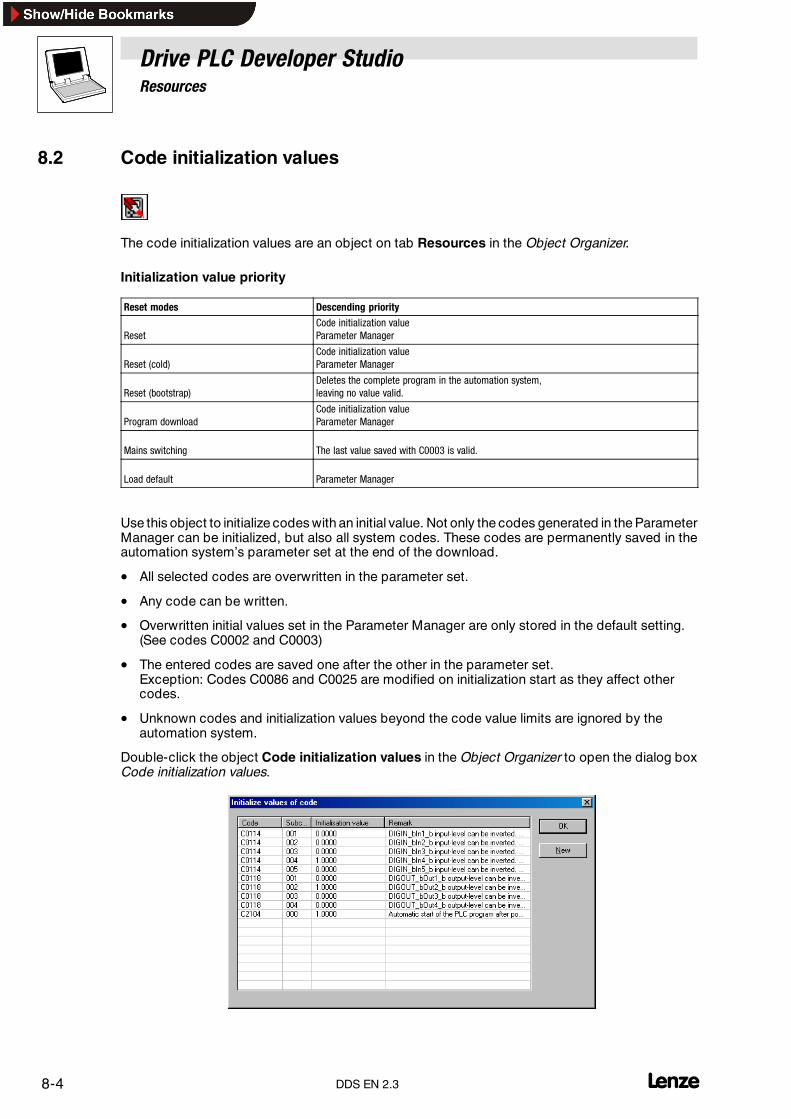
Drive PLC Developer StudioResources
8-4 lDDS EN 2.3
8.2 Code initialization values
The code initialization values are an object on tab Resources in the Object Organizer.
Initialization value priority
Reset modes Descending priority
ResetCode initialization valueParameter Manager
Reset (cold)Code initialization valueParameter Manager
Reset (bootstrap)Deletes the complete program in the automation system,leaving no value valid.
Program downloadCode initialization valueParameter Manager
Mains switching The last value saved with C0003 is valid.
Load default Parameter Manager
Use this object to initialize codes with an initial value. Not only the codes generated in the ParameterManager can be initialized, but also all system codes. These codes are permanently saved in theautomation system’s parameter set at the end of the download.
• All selected codes are overwritten in the parameter set.
• Any code can be written.
• Overwritten initial values set in the Parameter Manager are only stored in the default setting.(See codes C0002 and C0003)
• The entered codes are saved one after the other in the parameter set.Exception: Codes C0086 and C0025 are modified on initialization start as they affect othercodes.
• Unknown codes and initialization values beyond the code value limits are ignored by theautomation system.
Double-click the object Code initialization values in the Object Organizer to open the dialog boxCode initialization values.
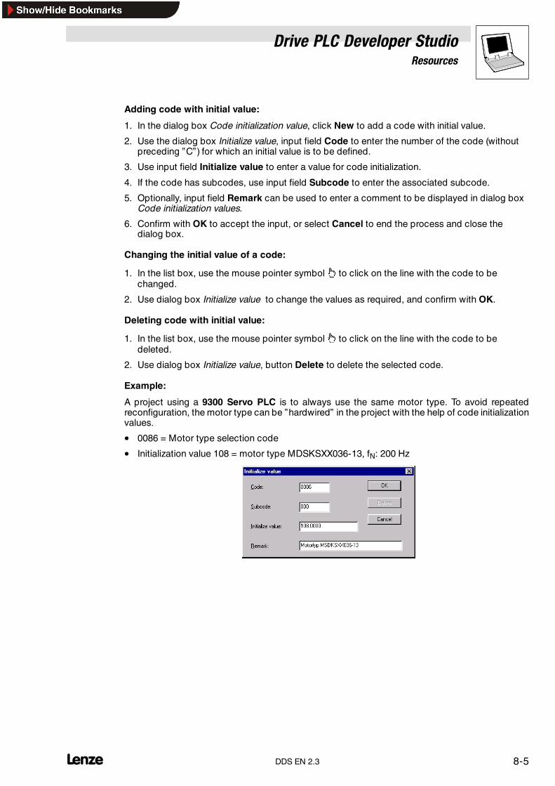
Drive PLC Developer StudioResources
8-5l DDS EN 2.3
Adding code with initial value:
1. In the dialog box Code initialization value, click New to add a code with initial value.
2. Use the dialog box Initialize value, input field Code to enter the number of the code (withoutpreceding ”C”) for which an initial value is to be defined.
3. Use input field Initialize value to enter a value for code initialization.
4. If the code has subcodes, use input field Subcode to enter the associated subcode.
5. Optionally, input field Remark can be used to enter a comment to be displayed in dialog boxCode initialization values.
6. Confirm with OK to accept the input, or select Cancel to end the process and close thedialog box.
Changing the initial value of a code:
1. In the list box, use the mouse pointer symbol to click on the line with the code to bechanged.
2. Use dialog box Initialize value to change the values as required, and confirm with OK.
Deleting code with initial value:
1. In the list box, use the mouse pointer symbol to click on the line with the code to bedeleted.
2. Use dialog box Initialize value, button Delete to delete the selected code.
Example:
A project using a 9300 Servo PLC is to always use the same motor type. To avoid repeatedreconfiguration, the motor type can be ”hardwired” in the project with the help of code initializationvalues.
• 0086 = Motor type selection code
• Initialization value 108 = motor type MDSKSXX036-13, fN: 200 Hz

Drive PLC Developer StudioResources
8-6 lDDS EN 2.3
8.3 Parameter monitor
The parameter monitor is an object on tab Resources in theObject Organizer.
Use the parameter monitor to parameterize codes online on the PLC. Parameterizable codes includecodes created via the Parameter Manager and those of the selected PC (e. g. 9300 Servo PLC, DrivePLC).
Tip!No modified code values will be saved in the project after log-out!
To save changes to code values, choose one of the following options.
Open the Object Organizer and double-click the object Parameter monitor to open the parametermonitor.
• Save the changes in the parameter set of the PLC (C0003=1).
• Save the changes in the project by entering the new values into the object Code initializationvalues in the Object Organizer. (� 8-4)
• Save the changes using the software tool Global Drive Control (GDC).
On its left, the parameter monitor shows a menu tree with folders assigned with codes or furthersubfolders.
• Folders identified with a plus sign contain subfolders.– Click on the plus sign to open the folder and to show the subordinate folders. A minus sign
now replaces the plus sign.– Click on the minus sign to hide the subfolders.
• Folders without a plus or minus sign do not contain subfolders, but codes.– Selecting such a folder will display the codes assigned to the folder on the right-hand side.– Read-only codes are shown in grey.– Codes whose values have not been read from the PLC yet are shown in green.
Drive PLC Developer StudioResources
8-7l DDS EN 2.3
8.3.1 System codes/User codes
There are system codes and user codes.
System codes
System codes are default codes ”hard-wired” into the PLC and can thus be used to parameterize thePLC with the help of parameterization tools such as GDC or keypad.
• These codes help set the monitor type, the constant of the speed controller, the feedbacksystem, the field bus, the terminal polarity, etc. for the 9300 Servo PLC, for example.
• The parameters for these codes can be set online on the PLC with the parameter monitor andsaved with C0003=1 in the parameter set of the PLC.
User codes
User codes are created in the Instance Parameter Manager and have a fixed link with a programvariable.
• These codes can be used to access variables in the PLC program via field bus profiles,parameterization programs and display and operating tools.
Grouping of codes
• The folder Code list contains all codes: The system codes of the selected PLC and the usercodes created in the project.
• The folder Individual IEC 61131 codes only contains the user codes created in the project.
• All other folders contain system codes of the selected PLC for the parameterization of aspecific functionality. The folder Multitasking contains all codes that can be used toparameterize the multitasking behaviour of the PLC.
8.3.2 Parameterizing codes
Tip!For code parameterization via the parameter monitor, the DDS must be connected online with thePLC.
• Click the code to be changed to open a dialog box for the modification of the selected code.
8.3.3 Differentiating between online and offline mode
Offline mode
• displays those write code values that were written last by the DDS.
• displays the preset read code values (in general 0).
Online mode
• reads the code values visible in the parameter monitor permanently from the PLC and displaysthem. Codes whose values have not been read from the PLC yet are shown in green.
• will not save any value changes to write-accessible codes made during a mains off. Only with“Save parameter set” (C0003=1) will the changed values be saved in the PLC’s parameter setand made available after mains switching.
The monitoring of variables is restricted while the parameter monitor is open.Variables may only be updated slowly or not at all.

Drive PLC Developer StudioResources
8-8 lDDS EN 2.3
8.4 Parameter Manager
IEC 61131-3 uses variables to initialize, process and buffer user data. These variables are declaredin the declaration part of every POU, i.e. the assignment to a specific data type (byte or integer) isadvised. This declaration can be used to define variable properties such as resistance to mainsfailure, defined initial values or assignments to fixed physical addresses.
Usually, variables are not used in controllers. Controller operation is based on codes. Field busprofiles, parameterization programs, operation and display tools use these codes to process thedata stored in the controller.
The Parameter Manager of the Drive PLC Developer Studio is a tool for linking codes and variablesand accessing variables via codes. User codes and codes of the Lenze function blocks can bemanaged by means of the Parameter Manager.
Parameter Manager
The user writes his IEC 61131-3 program using the Drive PLC Developer Studio and assigns a codeto specific variables to parameterize the program, for diagnostics or to exchange data viafieldbus/system bus in online operation.
• Variables of type VAR_IN_OUT and variables within a type VAR function block cannot beassigned codes.
Example: Lenze function block L_PT1_:
nDelayTime
nOut_a
L_PT1_
nIn_a
VariableName DataType SignalType VariableType
nIn_a Integer analog VAR_INPUT
nOut_a Integer analog VAR_OUTPUT
nDelayTime - - VAR CONSTANT RETAIN
Tip!Only codes assigned through the Parameter Manager can be displayed and parameterized viaGDC, Keypad or parameter monitor in the Drive PLC Developer Studio.
The remaining program structure (variables without code connection) cannot be accessed via theknown field bus profiles, parameterization programs, operating and display tools.
If, for example, the user assigns code C6000 to the variable nDelayTime, the parameterization anddiagnostics for the variable nDelayTime can be performed via this code. Only the codes assignedby the user can be diagnosed/parameterized using the parameterization environment.

Drive PLC Developer StudioResources
8-9l DDS EN 2.3
8.4.1 Add new objectIcon: - Menu: Insert�Add new object Keyboard: -
When a new object is created, the name of the organization unit, the variable, the variable type andthe variable class are displayed.

Drive PLC Developer StudioResources
8-10 lDDS EN 2.3
8.4.2 Terminology used by the Parameter Manager
Term Description
User codes User-specific codes (user codes) can be assigned for variables applied in the user’s IEC 61131-3 program.The user codes depend on the automation system and range between C3000 and C7999.
Code properties Code properties (read only, read/write, direct acceptance or direct acceptance when confirmed, forexample) can be defined for each assigned code.
Code value The code value is the value displayed or entered via the code (using GDC, Keypad or the parametermonitor).This variable corresponds to the physical value known as variable value in the user program(scaling).
Display text User-specified texts are displayed for parameterization/diagnostics using the Keypad. The text can have upto 13 characters and is displayed for the code.
Input window with yellowbackground colour
If the user changes a standard setting, the background colour of the field changes to yellow.In such cases, no changes in the Type Parameter Manager for this field will be considered.
Units Numerical values can also be assigned physical or defined units, such as rpm, Nm, bottles/min, etc.
First instances When using Lenze function blocks, the instances of these FBs (e.g. of 9300 Servo V2.0) can be assignedall Lenze parameter codes standard for FBs using the function First instance .Post-editing of the parameter codes is then not possible.The parameter code assignment can be revoked completely.Lenze function blocks can be linked with any codes.Lenze supplies code-parameterized function blocks for standard tasks.For PLC devices, the function blocks are used through linking a library (e.g. LenzeDrive.lib).If the function block (e. g. L_NSET) is to be assigned standard parameterization codes, the function blockwill be instanced as L_NSET1 of type L_NSET.First instancingThe codes, including scaling, for this function block can be created in the Parameter Manager.
Parameterization programlanguages
GDC or the parameter monitor display every code together with a max. 35 character long text forparameterization/diagnostics. This text can be defined in several languages (standardlanguage/language1/language2) in the Parameter Manager.The language can be selected when the GDC description file is created so that the user decides thelanguage to be used for text displays.
Initialization An initial value can be assigned to the code to be accepted as initial value in the code’s default setting(C0002).
Instance Parameter Manager Assignment of codes for variables used by the created program POUs or for the global variables of aproject.
Scale factor/scale function Internal variables can be shown more transparently using scale factors.The IEC 61131-3 program uses a 16-bit value (e.g. integer) for example, while the scale function allows avalue between �200% to be set in the GDC. The 16-bit value is simply scaled from �32767 to �200.The user can define the limits of the value range in the code, so that the integer value of the code can onlybe set between �16384 � �100%, for exampleScale functions allow complex scaling operations. Scale functions are small IEC 61131-3 programs andcan be programmed by the user. The program may contain internal conversion scaling operations, limitvalue calculations, etc.
Subcodes Subcodes are assigned automatically if the variable is an Array data type.Example:var1:ARRAY[0..4] OF INT(up to 5 subcodes assigned)All subcodes are given the same initialization value in the Parameter Manager.
Type Parameter Manager Definition of a standard settingPredefinition of variables of created function block POUs
Variable types Variables of type VAR_IN_OUT and variables within a type VAR function block cannot be assignedcodes.
Variable value The variable value is the value processed in the IEC 61131-3 program (e. g. integer value of 16384).

Drive PLC Developer StudioResources
8-11l DDS EN 2.3
8.4.3 Instance Parameter Manager
The Instance Parameter Manager is an object on the tab Resources in theObject Organizer. It allows the user to assign codes to the variables declared in the project.
• The variables can be declared globally or locally in Program-type POUs.
• Once the Instance Parameter Manager has been started, codes can be assigned for theentire project.
Tip!The available first instances of a function block are described in the relevant manual for the functionlibrary and in the online help, chapter ”Lenze function libraries” .
8.4.3.1 Opening the Instance Parameter ManagerIn theObject Organizer, double-click theobject Instance Parameter Manager to open the InstanceParameter Manager.
• The Instance Parameter Manager displays information on already assigned codes.
• Frequently required commands are also available via the shortcut menu (right mouse key):
Tip!Use the buttons Code number and Program organization unit in the top line of the list to definethe sorting order for entry display:
• Click Code number to sort the entries by ascending code numbers.
• Click Program organization unit to sort the entries alphabetically and in ascending order byprogram organization unit and variable names.
8.4.3.2 Editing codesSettings for already assigned codes can be edited by
• double-clicking the associated line- or -
• selecting the associated line and clicking Insert�Process the object....
This will open the dialog box Instance Parameter Manager where the settings for a code can beedited. (� 8-12)

Drive PLC Developer StudioResources
8-12 lDDS EN 2.3
8.4.3.3 Adding codes
Select Insert�Add new object to add a new code.
Note!It is not permissible to create codes on system variables.
No codes can be created for REAL variables.
• Open the dialog box Enter the new object to select the variable to be linked to the code.
• Selection of the variable and confirmation with OK will open the dialog box InstanceParameter Manager where the settings for a code can be made.
The Instance Parameter Manager supports the following data types.
• BOOL
• BYTE
• SINT
• USINT
• INT
• UINT
• DINT
• UDINT
• WORD
• DWORD
Note!Copy and insert actions on objects will completely replace the contents.
8.4.3.4 Dialog box Instance Parameter Manager
Open the dialog box Instance Parameter Manager to edit the settings for an existing or specify thesettings for a new code.
Note!System variables must not be linked with write/read codes.
Code/index
• The code range from C3000 to C7999 is available. Code numbers are entered without theleading ’C’.
• Clicking the button First instance inserts the known parameter code in the input field Code.The input fields Code max./Code min. and Int. max./Int. min. are greyed out.
• Selecting an existing code will return an error message on clicking OK.

Drive PLC Developer StudioResources
8-13l DDS EN 2.3
Code max./ Int. max. and Code min./ Int. min.
These four input fields are used to define input limits and to scale the code value.
Use the input fields Code max./Code min. to enter the limits the code value will be checked forwhen written. If the limits are not adhered to during writing, the code value will be rejected by theruntime system.
Together with the values entered in Int. max./Int. min., an assignment is made between code valueand scaled variable value used in the program. Scaling uses a lineequation whosegradient and zeropoint are determined by the specified four factors.
The line equation is:
m = int. Max.− int. Min.Codest. Max.− Codest. Min
Variable value= m(Code value− Code. Max.)+ Int. Max.
Example:
• The code limits are to be between �100%
• The variable limits are to be between �16384 (integer)
• Calculate the variable value at a set code value of 50%.
m = 16384− (− 16384)100%− (-100%)
Variable value= m(50%− 100%)+ 16384= 8192
At a code value of 50% the variable value is 8192. This calculation shows that it is possible to enteran external code value of 50% while calculating internally with the variable value 8192. Thus thevalue was scaled by 50% to 8192.
Scale function
Scale functions can be inserted for POUs as optional subprograms (IEC 61131-3 program). Sucha program can be used to program a complex scaling of a variable with an assigned code. ReferType Parameter Manager: “Scale functions” (� 8-18)
Access
Use the group field Access to define whether the code can be read and written or read only.
Initialization
Use the input field Initialization to enter the code value to be used to initialize thevariable by loading”C0002 = Default setting” . The initialization value (code value)is the scaled value, i. e. the initial valueis scaled by means of the scale factors before it can be used as variable value in the IEC 61131-3program.
• The initial value of the Parameter Manager has priority if a variable was initialized with a valuein both the declaration editor and the Parameter Manager.
Tip!Initialization is also possible when no code is assigned.
A variable can be initialized with a scaled value that is transferred on launching the PLC program.The advantage of this is that physical values are used as initial values, for example.
Unit
Use the list field Unit to assign a physical or fictitious unit to the code. Use the button New to definenew application-specific units (e. g. bottles/minute).

Drive PLC Developer StudioResources
8-14 lDDS EN 2.3
Ext. data type
Use the field Ext. data type to assign one of the following special data types to a code:
Data type Decimal code Length Polarity
Fixed point* four fixed decimal positions 32 bit with
8 bit with polarity none 8 bit with
16 bit with polarity none 16 bit with
32 bit with polarity none 32 bit with
8 bit without polarity none 8 bit without
16 bit without polarity none 16 bit without
32 bit without polarity none 32 bit without
* 1.0000 corresponds to an external specification of 10000, for example. The last four digits are the decimals.
Display
Use the group field Display to define parameterization settings via Keypad.
• Use the input field Text to enter display text for the code that will be displayed on theKeypad. The text is limited to 13 characters.
• If the box Confirmation is activated, the SHIFT and the PRG key on the Keypad must bepressed at the same time to accept the code value of the respective code. This setting willnot be considered for read-only codes.– RSP
Code can only be changed when the controller is inhibited.– PLC Stop
Code can only be changed when the PLC is stopped.
Parameterization program
Use the group field Parameterization program to enter code texts for display in GDC and theparameter monitor.
• One of three text options can be selected when generating the device description for GDC.
• These entries are important for the generation of GDC description files in different nationallanguages.
Selection list
Select option Selection list to assign freely definable text to code values in theassociated text inputfield:
• These settings will not be considered for read-only codes.
• Complete selection lists are available for the first instances of Lenze function blocks fromlibraries. These lists can be accepted, extended or modified.
• Selection lists to be accepted by the Instance Parameter Manager can be predefined via theType Parameter Manager.
• Any predefined lists used will be updated automatically if the original files (libraries, functionblock POUs) were changed.
• Changes to a predefined list will change its background colour from grey to yellow. Automaticupdates will no longer be carried out.
• Only code values defined in the selection list can be addressed via the parameterizationenvironment.

Drive PLC Developer StudioResources
8-15l DDS EN 2.3
Button “First instance”
Clicking the button First instance inserts the known parameter code in the input field Code. Theinput fields Code max./Code min. and Int. max./Int. min. are greyed out.
Button ”Standard”
Use the button Standard to accept the standard settings of the variables.This means:• The settings will be accepted for variables set in the Type Parameter Manager, leaving only
the code to be assigned.• The limits of the data type set in the declaration editor will be accepted for variables that are
not yet known at this point.If the user makes any retrospect changes, the background colour of the associated input fieldchanges to yellow to show it is different from the type definition.Retrospect changes made in the Type Parameter Manager or data type changes in the declarationeditor are automatically updated for the associated code.
8.4.3.5 Handling Lenze function blocksIf you use Lenze function blocks in POUs of type Program, VAR CONSTANT RETAIN variables ofthese FBs can be assigned all known parameter codes (e.g. 9300 servo inverter V2.0) using theParameter Manager. These assignments can of course be revoked again.Use the correct instance name in the declaration editor of the Program-type POU for thisassignment:• The instance name is the name of the function block followed by a number (1, 2, 3, ...)• This syntax is valid for all Lenze function blocks.• If the syntax is changed, only user codes (C3000 - C7999) can be assigned to the instances.
Example of the exact declaration based on function block L_DIGDELfor the 9300 Servo PLC:
If the function block L_DIGDEL from the Lenze library LenzeDrive.lib is used in a Program-typePOU, for example, the FB instance name must be exactly L_DIGDEL1 (L_DIGDEL1 of functionblock type L_DIGDEL):
• Only with the correct selection of the FB instance name can the known parameter codes (seetable below) of the 9300 Servo PLC be assigned to the function block by clicking Firstinstance.
• Further instances are then named L_DIGDEL2, L_DIGDEL3, etc.Note that only L_DIGDEL1 andL_DIGDEL2 can be assigned the parameter codes of the 9300Servo PLC because this PLC has only two instances of this function block. Further instances (e. g.L_DIGDEL3) can only be assigned user codes.
Tip!The available instances of a function block are described in the online help, chapter “Lenze functionlibraries” .
If variables from Lenze function blocks are linked with codes, setting ranges and scaling operationsmust be set in accordance with the documentation.

Drive PLC Developer StudioResources
8-16 lDDS EN 2.3
Example: Instances of the function block L_DIGDEL of the 9300 Servo PLC
Variable name L_DIGDEL1 L_DIGDEL2 Setting range Lenze
byFunction C0720 0 ... 2 2y
C0725 0
wDelayTime C0721 C0726 0.001 ... 60.000 s 1.000
Tip!Parameter variables can only be read in the PLC program, not written.
Example:
LD L_DIGDEL1.byFunctionST variable_x
The VAR CONSTANT RETAIN variable can only be accessed via the assigned code.
• Use the FB L_ParWrite from the function library ”LenzeDrive.lib” to write codes in PLCprograms.
Accepting all Lenze codes of a function block
Open the dialog box Instance Parameter Manager and click the button First instance to assign theassociated code only to the selected variable.
To accept all Lenze codes of the function block instance, select a variable of the associated functionblock in the Instance Parameter Manager and click Insert�Adapt Lenze initial codes.
• This command is also available in the shortcut menu:
Command execution creates all codes of the function block instance in the Instance ParameterManager (in this example: L_DIGDEL1.wDelayTime):
8.4.3.6 Accessing arrays via subcodesAccess to individual array fields by means of codes (e. g. using the Keypad, for example) is viaso-called subcodes.
Subcodes are a code subset of a master code.
Example:
C6000 Master codeC6000/1 Subcode 1C6000/2 Subcode 2... ...C6000/n Subcode n

Drive PLC Developer StudioResources
8-17l DDS EN 2.3
Generating subcodes
The Parameter Manager can only assign subcodes to variables of the type ARRAY OFObserve thefollowing:
• Only the master code need be defined. The subcodes are generated automatically accordingto the array length.
• Subcode 1 is always the first element of the array.
• Subcodes are set globally through the master code, i. e. each subcode has the sameconfiguration as the master code. As this also applies to display texts, select a general text torule out misunderstandings.
• Use the parameter monitor for individual subcode settings. (� 8-6)
Example: Relationship between field variables and subcodes
Variable in PLC program: Assigned code:
X: ARRAY [0..4] OF INT C6000
Array fields: Automatically generated subcodes:
X[0] C6000/1
X[1] C6000/2
X[2] C6000/3
X[3] C6000/4
X[4] C6000/5
8.4.3.7 Data exportIcon: - Menu: Extras�CSV export Keyboard: -
If the instance parameter manager is active, this menu command can beused to export thecontentsof the instance parameter manager.
The export file with the name *.csv is saved in the same file folder as the DDS project file with thename *.pro. CSV (comma sequented values) saves the data of the instance parameter managerusing the same column pattern. For future processing the file can e.g. be opened with Excel.
Tip!Do not open the file directly in the Explorer via adouble-click, but via themenu command file�openin Excel in order to improve configuring of the export file.
Drive PLC Developer StudioResources
8-18 lDDS EN 2.3
8.4.4 Type Parameter Manager
The Type Parameter Manager is an object on the tab Resources in theObject Organizer.
For the use of libraries or POUs of type Function block in a project, the limits/scaling operations ofthe variables, among other things, can be predefined using the Type Parameter Manager.
If a function block created in the Type Parameter Manager is called in a Program-type POU, thesettings defined in the Type Parameter Manager will be accepted in the Instance ParameterManager by pressing the button Standard.
Tip!The Type Parameter Manager handles analogously to the Instance Parameter Manager, the onlydifference being the selection of a function block type instead of a function block instance. For moreinformation on how to use the Type Parameter Manager, refer to the chapters on the InstanceParameter Manager. (� 8-11)
8.4.5 Scale functions
Codes can be linked with a scale function.
• A scale function is an IEC 61131 program written by the user for the scaling of theseparameters/variables.
Scale function for codes with write access
If a code value changes, the value of the linked variable will change too. (Every) code write canlaunch a user-generated scale function.
• If processing of the associated scale function is to be rejected on write access to a code as aconsequence of a condition, the value of variable g_bScaleFunctionError in the scalefunction must be set to TRUE.The global variable g_bScaleFunctionError of type BOOL is included in Standard.lib
Scale function for codes with read access
Read access to a code with a parameterization tool (e. g. GDC, Keypad or HMI) may launch auser-generated scale function.
• For this purpose, a write must be performed to the associated scaling variable in the scalefunction.
• The value of the scaling variable is output via the code after linear scaling.
• The scaling variable is a global variable of Standard.lib and must be selected according tothe data type:
g_fScaleFunctionReal : REAL;g_fScaleFunctionByte : BYTE;g_fScaleFunctionSint : SINT;g_fScaleFunctionInt : INT;g_fScaleFunctionWord : WORD;g_fScaleFunctionDint : DINT;g_fScaleFunctionDword: DWORD;g_fScaleFunctionBool : BOOL;
Example:
• If the display code is assigned to a variable of type BYTE, a write must be performed tog_fScaleFunctionByte in the associated scale function.

Drive PLC Developer StudioResources
8-19l DDS EN 2.3
Generating a scale function
1. Open the Object Organizer, tab Organization units and select the function block you want toassign a scale function to.
2. Select Project�Add scale function to open the dialog box Add scale function.
3. Open the dialog box Add scale function to select the programming language and theassociated variable. The name of the scale function will be assigned automatically (”SCAL_”+ variable name).
4. Use the button Add to add the scale function or Close to cancel the process and close thedialog box.
The scale function is inserted underneath the associated FB in the Object Organizer. Double-clickthe scale function in the editor to open and program it.
Using system organization units in scale functions
If a system organization unit is used in a scale function, it must be used in at least one other POU.Otherwise no process image is crea ted for the system organization unit. PLC_PRG or another POUcalled by a task can be used as a POU, for example.
If system organization units are only used in scale functions or system POUs, no process image iscreated for them as these organization units are not assigned to any task.Problems may occur if a system organization unit is used in other tasks, thus leading to the creationof a process image (on PLC_Coldstart, for example).A warning is given from DDS version 2.0 if system organization units are used in scale functions andsystem POUs.
Use of scale functions in global function block instances results in a PI trip in the automation system.A compiler error is output from DDS version 2.0 if a scale function is used in a global function blockinstance.
Note!Check in the process image monitor that a process image is created for the system organizationunit used in the scale function.
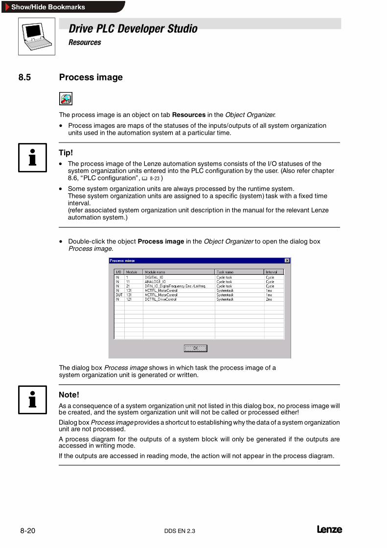
Drive PLC Developer StudioResources
8-20 lDDS EN 2.3
8.5 Process image
The process image is an object on tab Resources in the Object Organizer.
• Process images are maps of the statuses of the inputs/outputs of all system organizationunits used in the automation system at a particular time.
Tip!• The process image of the Lenze automation systems consists of the I/O statuses of the
system organization units entered into the PLC configuration by the user. (Also refer chapter8.6, “PLC configuration” , � 8-23 )
• Some system organization units are always processed by the runtime system.These system organization units are assigned to a specific (system) task with a fixed timeinterval.(refer associated system organization unit description in the manual for the relevant Lenzeautomation system.)
• Double-click the object Process image in the Object Organizer to open the dialog boxProcess image.
The dialog box Process image shows in which task the process image of asystem organization unit is generated or written.
Note!As a consequence of a system organization unit not listed in this dialog box, no process image willbe created, and the system organization unit will not be called or processed either!
Dialog box Process image provides a shortcut to establishing why the data of a system organizationunit are not processed.
A process diagram for the outputs of a system block will only be generated if the outputs areaccessed in writing mode.
If the outputs are accessed in reading mode, the action will not appear in the process diagram.

Drive PLC Developer StudioResources
8-21l DDS EN 2.3
I/O Display whether inputs (IN) or outputs (OUT) of the system block are concerned.
Module no. Module number of the associated system organization unit(for module numbers refer associated manual for the automation system or online help, chapter“Lenze automation systems”)
Module name Name of the system organization unit
Task name Name of the task where the associated process image of a system organization unit is generated or written.• Either the task name selected in the task configuration or the cyclical task or system task
(certain system organization units are assigned to the system task).• The system automatically determines the optimized time cycle for the system organization unit.
Interval This column specifies the time cycle for process image updates.
Tip!Check before the download whether all applied system organization blocks are listed in the dialogbox Process image to detect errors quickly.
8.5.1 Generating the process image
The process image consists of
• Process input image = Status of all system organization unit inputs
• Process output image = Status of all system organization unit outputs
Cyclical task (PLC_PRG)
If only one cyclical task is used, the process input image of the system organization units used forthis task will be read at the beginning of the cyclical task, and the process output image will berestored at the end of the cyclical task.
• During processing of the automation system program, the status information of the processinput image will remain constant, and data consistency is ensured.
• Process image updates depend on the processing time of the cyclical task, in other words,program length and complexity.
Time-controlled task (INTERVAL)
If INTERVAL tasks are used, the process input image of the system organization blocks used for thistask will be read at the beginning of the INTERVAL task and the process output image be restoredat the end of the INTERVALtask.
• If a certain system organization unit is used in several INTERVAL tasks, the associatedprocess image will be generated in the faster INTERVAL task (independent of whether thissystem organization unit is also used in the cyclical task).
Tip!Note that the INTERVAL task may be slower than the cyclical task.
It may be necessary to install a fast task for the process image to ensure that only the process imageis updated in time.
Example:
Analog input 1 is used in the cyclical task (runtime: 40 ms) and in an INTERVAL task(runtime: 3 ms).
• The process image for analog input 1 is now updated every 3 ms. The cyclical task receivesan updated value every 3 ms during processing (40 ms).

Drive PLC Developer StudioResources
8-22 lDDS EN 2.3
Tip!Note that data inconsistencies may occur if analog input 1 is used several times within the cyclicaltask.
• As the process image is updated every 3 ms within the 40 ms of cyclical task processing,there may be different input values for analog input 1.
Event-controlled task (EVENT)
• If system organization units are used in one event-controlled task only, their process imagewill be generated in the event-controlled task.
• If the same system organization units (that are not also used in a time-controlled task) areused in two event-controlled tasks, their process image will be generated in the cyclical task.
Tip!For further information about tasks, refer chapter 8.8, “Task configuration” . (� 8-29)
Interrupt-controlled task
• If system organization units are used in one event-controlled task only, their process imagewill be generated in the event-controlled task.
• If the same system organization units (that are not also used in a time-controlled task) areused in an event-controlled and an interrupt-controlled task, their process image will becreated in the cyclical task.

Drive PLC Developer StudioResources
8-23l DDS EN 2.3
8.6 PLC configuration
The PLC configuration is an object on tab Resources in the Object Organizer and combines theresources of the automation system.
The dialog box PLC Configuration describes the selected automation system for the project.
The resources of theautomationsystem aredescribed by theapplied system organization units. Theavailable system organization units are dependent on the selected automation system.
• The editor displays the configuration as a tree structure that can be edited via menucommands and dialogs.
• In the PLC configuration, the system organization units are attached to the automationsystem as subordinate elements.
• The editor displays inputs and outputs with an IEC address for input and output access. Instandard cases, a symbolic name may be assigned for each input and output foridentification, that will then be placed in front of the IEC address.
• Any projects opened that were generated with an older DDS version and containing a PLCconfiguration, can be transferred into the new Uniform Control Configuration format.(� 8-25)
• It is important for program generation to insert the required system organization units of theselected Lenze automation system.
System organization units
System organization units are interfaces/organization units permanently integrated into the device(quasi hardware interfaces)that cannot be programmed using the DDS(e. g. MCTRL_MotorControl,DIGITAL_IO, DCTRL_DriveControl, AIF_IO, ANALOG1_IO, ...)
• The DDS checks on the basis of the relevant system organization unit description whether theIEC addresses applied in the program do indeed exist in the automation system.
The system organization units in the PLC configuration consist of several elements that are eitherinputs or outputs.
• Every input/output has a symbolic name (identifier) that can be changed if necessary and isassigned an IEC address. Thus every input/output can be addressed directly (e. g. %IX1.0.1)or via system variables (DIGIN_bIn1_b) in the program.

Drive PLC Developer StudioResources
8-24 lDDS EN 2.3
8.6.1 Working in the PLC configuration
The configuration editor consists of two window panes.
The left-hand window pane provides a structured representation of the module inputs and outputs.If an organization unit is selected, the data are shown in the right-hand window pane under basicparameters.
The top level of the dialog box PLC configuration includes the name of the selected automationsystem.
Elements identified with a plus sign are organization elements and contain subelements.
• Click the plus sign to show the subelements. Click the minus sign to hide the subelementsagain.
• Double-click an element to change the input/output variable names.
The variables/direct addresses of the system organization unit inputs/outputs can now be called assystem variables in the POUs for programming.
Tip!Themost essential commands for the dialog box PLC configuration arealso available in theshortcutmenu (right mouse key) or via <Umschalt>�<F10>.
PLC configuration in online mode
Note!Only if the automation system is operating does the PLC configuration display the statuses of thecontrol inputs and outputs in online mode.
• If a Boolean input or output has a value TRUE, the small box in front of the input or output willbe shown in blue.
• Variable values will be displayed with their current value.
Boolean inputs can be toggled by mouse click, other inputs are displayed a dialog box where a newvalue can be entered. The new value will be set in the control immediately after its confirmation withOK.
8.6.1.1 PropertiesIcon: - Menu: Extras �Properties Keyboard: -
Use this command to open a dialog box to save more information (such as a comment, for example)with the input/output module selected in the PLC configuration.
8.6.1.2 Insert elementIcon: - Menu: Insert�Insert element Keyboard: -
Use this command to insert theselected element into thePLC configuration in front of thehighlightedelement.
8.6.1.3 Add subelementIcon: - Menu: Insert�Add subelement Keyboard: -
Use this command to insert the selected element into the PLC configuration as the last subelementto the highlighted element.

Drive PLC Developer StudioResources
8-25l DDS EN 2.3
8.6.1.4 Replace elementIcon: - Menu: Extras�Replace element Keyboard: -
A correctly defined configuration file allows an element selected in the configuration tree to bereplaced with another. This also includes the switching of channels so that they can be used withthe configuration as input or output.
8.6.1.5 Calculate addressesIcon: - Menu: Extras�Calculate addresses Keyboard: -
Note!Not all automation systems support this function.
Execution of this menu item requires the check box Calculate addresses to be selected in thegeneral PLC configuration settings.
Calculate addresses applies from the selected module and includes all of the elements below.
8.6.1.6 Default configurationIcon: - Menu: Extras�Default configuration Keyboard: -
Use this command to delete the set configuration and to return to the original configuration.
8.6.1.7 Convert old PLC configurationsIcon: - Menu: Extras�Convert Keyboard: -
Use this command to convert any project opened that includes a PLC configuration generated withan older DDS version into the format of the current PLC configuration.
Convert the older project only if you require, and want to use, the functions of DDS 2.x.
Note!The old configuration cannot be restored.

Drive PLC Developer StudioResources
8-26 lDDS EN 2.3
8.6.2 Touch probe interface
Some automation systems allow the use of digital inputs optionally as touch probe input or simpledigital input.
Inputs are configured via the PLC configuration in the DDS.
Note!The source for the last scan value can be configured via the field Registerparameter.
Observe the following when using digital inputs as touch probe.
• If a digital input is used as a touch probe it can not be used to start a task.
• Every touch probe input is assigned a task to reduce the number of interrupt tasks availablefor the application.
8.6.3 Configuring an I/O module
Once an I/O module has been selected in the configuration tree, the system displays the dialog boxBasic parameters with the following options:
Module ID
This is an unequivocal module identifier within the entire configuration environment, taken from theconfiguration file and cannot be edited.
Node number
The node number results from an entry in the configuration file. If there is no entry there, it is sourcedfrom the position within the configuration tree.
8.6.4 Configuring a channel
Basic parameters of a channel
Once a channel has been selected in the configuration tree, the system displays the dialog boxBasic parameters.
Comment
Additional channel-specific information. The text field allows a comment to be edited or a new oneto be entered.
Channel ID
Globally unique channel ID.

Drive PLC Developer StudioResources
8-27l DDS EN 2.3
Class
Information on channel application
I Input
Q Output
I&Q Input and output
I|Q Input or output (can be toggled)
Size
Channel range size
Default identifier
Symbolic channel name assigned in the configuration file. The channel name is assigned into theconfiguration file and can be edited in the configuration tree.
Channel parameters
This dialog box, analogous to the dialog box Module parameters, allows the channel parametervalues to be displayed and modified.
As for the modules, it may be substituted with an application-specific dialog box Customparameters .
Bit channels
The basic parameters of bit channels only feature the input field Comment.

Drive PLC Developer StudioResources
8-28 lDDS EN 2.3
8.7 Task monitor
The task monitor is an object on the tab Resources in the Object Organizer.
If the PC is connected online with an automation system, the runtime of the individual tasks can bediagnosed via the task monitor. In offline mode, the task monitor displays the last online task status.
• Open the Object Organizer and double-click the object Task monitor to open the taskmonitor:
The tasks are displayed in lines along with the following information:
Column Display
Id Id of the task (0 ... 9) as well as the status of the task:� = Task is ready or runningST = Task is blocked or inhibited
Name Task name
Last runtime Runtime of the last task processing run.
Maximum runtime Maximum runtime during program operation
Load Bar graphs with the currently detected task time of an interval task• Green bars: The current task time is less than 80 % of the interval time.• Red bars: The current task time is greater than 80 % of the interval time.• The column width represents 100 % of the interval time.• The black line indicates the maximum task runtime (peak hold) during program operation.• In offline mode, this time is displayed as a figure in percent of the interval time.
Status Task status (running, inhibited or interrupted).
Error “Overflow”: The task needs more time than the set watchdog time.“No error”: The task is processed within the specified watchdog time.
Priority Task priority
Type Task type (interval, cyclical, event or interrupt).
Interval Interval time of an interval task.
Event Event of an event or interrupt task
Watchdog time Task watchdog time
Tip!The displayed task runtimes are not the net times but the real runtimes including all taskinterruptions at a 25.6 µs resolution.
Cyclical task/system task
• The system task processes any necessary internal system tasks in the background.
• The cyclical task does not only contain the task PLC_PRG, but also the task of communicatingwith the PC.
• System and cyclical tasks apply the time slicing principle to share the low-priority cyclicallyprocessing task.

Drive PLC Developer StudioResources
8-29l DDS EN 2.3
8.8 Task configuration
The task configuration is an object on the tab Resources in theObject Organizer.
8.8.1 Task definition
IEC 61131-3 refers to a group of PROGRAM-type POUs as a ”task”. POUs are software units usedto organize the project (POU = Program Organization Unit).
The task is executed by the runtime system and the program/s included in it ensure the requiredfunctionality of the runtime system.
Task types
Lenze automation systems, for example 9300 Servo PLC, Drive PLC, support four different tasktypes:
• Cyclical task (PLC_PRG)PLC_PRG is the main loop of the user program (number: 1).It is always active, has the lowest priority and cannot be switched off.PLC_PRG can be created in the required programming language, and other program POUscan be called from PLC_PRGThe use of PLC_PRG is not absolutely necessary for a control program.The runtime of PLC_PRG is not equidistant, i.e. it depends on the program size and thecurrent processor load.
• Time-controlled task (INTERVAL)Set up time-controlled tasks that can be started periodically.The period duration can be set in 1 ms steps between 1 ms and 16 s.
• Event-controlled task (EVENT)Set up event-controlled tasks to be started through a “Boolean change” of a definablevariable or a hardware input of the PLC. The variable can be a global variable or a systemvariable.Response time = 1 ms.
• Interrupt taskThis task can be started through a real hardware interrupt (digital input). This interrupt is nottriggered via the IEC 61131-3 program, but via the processor. The advantage is that the taskcan be started very quickly.Typical response time = 100 µs; “Worst case” response time = 250 µs.
The number of tasks (time-controlled, event-controlled or interrupt) is dependent on the selectedautomation system.
Note!The runtime system monitors the processing time of all tasks.
If processing takes too long or is interrupted frequently by higher-priority tasks, thus extending theprocessing time beyond the cycle time of a task, for example, a system error will occur and crashthe runtime system.
Task properties are set through the DDS in adherence to the following conditions:
Event-controlled task (Interrupt/EVENT)
With an event-controlled task, the Boolean status of the associated variable or the hardwareinterrupt must change from FALSE to TRUE) to start this task.
• The initial status TRUE of the variable does not start the task!

Drive PLC Developer StudioResources
8-30 lDDS EN 2.3
Saving a start event
If an EVENT-type task is called again during processing, the new call is saved and restartedimmediately after the task cycle of the event-controlled task is complete. Only one call can bebuffered.
PRIORITY
Every user task (not the Cyclical task) has a defined priority between 0 and n(0 = task never starts; 1 = highest priority ...n-1 = second-lowest priority ...n = lowest priority).
• A priority cannot be assigned twice. It is thus not possible to have two tasks with the samepriority.
• The priority of a task can not be changed while the automation system runs in online mode.
• The priority of a task decides whether another currently processed task will be interrupted ornot. If a lower-priority task is started while a task is running, the lower-priority task will waitand not interrupt the running task.
8.8.2 Data consistency
Multitasking operating systems or, in general, all software structures featuring “concurrent”processes running at different cycle times, have a problem with data inconsistency, which we willbriefly look into at this point.
When do data inconsistencies occur?
• Variable A is used in different places within routine 1. At routine 1 runtime, variable A ischanged by a routine 2.
• A data record consists of 4 variables that must be checked out from the memory for reading.An Interrupt-Service-Routine 2 changes this data record during the read access.
8.8.3 Normal data processing/IPO principle
Normal data processing for simple PLC systems, for example, always follows the IPO principle(input/processing/output) where the data inconsistency problem does not occur!
The IPO principle deals with only one data processing branch:
• All data required are read at the beginning of the loop.
• In the middle of the loop, the data are processed and the output values calculated.
• The data are output at the end of the loop (just before the ” loopback”).
INPUT
PROCESS
OUTPUT
With this method, the input data are the same and constant during the entire processing time untilthe new read at the beginning of the loop. Since there are no further processes that interrupt the IPOprocess during the runtime of the loop and may access data of the running process, there is noreason for data to become inconsistent !

Drive PLC Developer StudioResources
8-31l DDS EN 2.3
8.8.4 If a task overflow leads to a system error
If, for instance, a continuous loop or too much program content has been programmed for a taskand the task cannot process the program within the specified interval time, a system error will occurin the automation system.
System errors can also occur when a running task is interrupted so frequently by other tasks thatthe program cannot be processed within the specified task runtime.
A system error trips the automation system.
• The response of motor control and digital outputs can be set underProject����Exception handling.(also refer associated system organization unit description in the manual for the respectiveLenze automation system.)
• The program can only be restarted after a TRIP reset or mains switching.
A TRIP reset (Keypad: STOPRUN key; GDC: Code C0043) resets the Lenze automation systemafter a task overflow, and the error message “Task overflow” is acknowledged.The automationsystem must be corrected to prevent further task overflows.
The watchdog time is set as follows:
• Use the task dialog box Properties, input field Watchdog time to enter the maximum runtimefor the task.
• Interval: The watchdog time is between 0-100 % of the interval time (default=90 %) and canbe set between 1 ms and 300 ms.(With a 1 ms task, the watchdog time is 1 ms = 100 % fixed.)
• Event/Interrupt: The watchdog time can only be set less than 300 ms (default=100 ms).
• Use the dialog box Exception handling (Project�Exception handling), input fieldWatchdog time to enter the maximum runtime for the cyclical task (PLC_PRG).
Tripping the watchdog time
• Tripping the watchdog time activates an error message in the PLC.
• This error message is displayed on the Keypad/in GDC in code C0168.
• After TRIP reset, error message and PLC program will be reset. Use the DDS start commandor C2108=1 to restart the program.
8.8.5 Task declaration
A task declaration consists of the task name, the entry for task priority and the condition for itsexecution.
The condition can be a time interval (1 ms to 16 s) after which the task is to be executed, an event(rising edge at the digital input or FALSE/TRUE change of a global variable) or a hardware interrupt.
Every task can now be assigned a list of programs (Program-type POUs) to be called by the task.These programs are processed in the listed order.
Tip!The task settings (properties) cannot be changed in online mode!
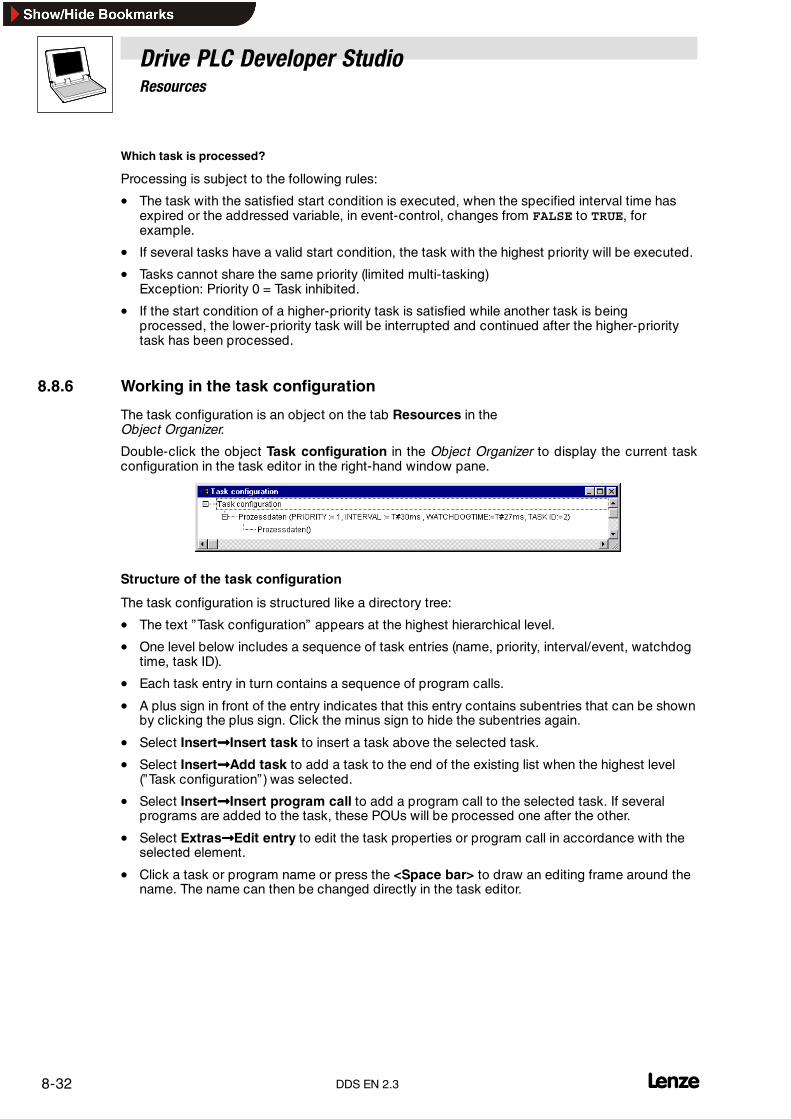
Drive PLC Developer StudioResources
8-32 lDDS EN 2.3
Which task is processed?
Processing is subject to the following rules:
• The task with the satisfied start condition is executed, when the specified interval time hasexpired or the addressed variable, in event-control, changes from FALSE to TRUE, forexample.
• If several tasks have a valid start condition, the task with the highest priority will be executed.
• Tasks cannot share the same priority (limited multi-tasking)Exception: Priority 0 = Task inhibited.
• If the start condition of a higher-priority task is satisfied while another task is beingprocessed, the lower-priority task will be interrupted and continued after the higher-prioritytask has been processed.
8.8.6 Working in the task configuration
The task configuration is an object on the tab Resources in theObject Organizer.
Double-click the object Task configuration in the Object Organizer to display the current taskconfiguration in the task editor in the right-hand window pane.
Structure of the task configuration
The task configuration is structured like a directory tree:
• The text ”Task configuration” appears at the highest hierarchical level.
• One level below includes a sequence of task entries (name, priority, interval/event, watchdogtime, task ID).
• Each task entry in turn contains a sequence of program calls.
• A plus sign in front of the entry indicates that this entry contains subentries that can be shownby clicking the plus sign. Click the minus sign to hide the subentries again.
• Select Insert����Insert task to insert a task above the selected task.
• Select Insert����Add task to add a task to the end of the existing list when the highest level(”Task configuration”) was selected.
• Select Insert����Insert program call to add a program call to the selected task. If severalprograms are added to the task, these POUs will be processed one after the other.
• Select Extras����Edit entry to edit the task properties or program call in accordance with theselected element.
• Click a task or program name or press the <Space bar> to draw an editing frame around thename. The name can then be changed directly in the task editor.
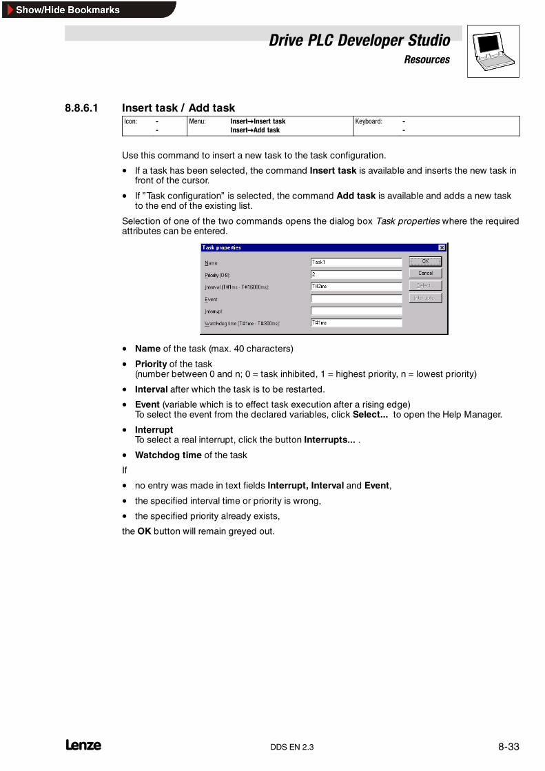
Drive PLC Developer StudioResources
8-33l DDS EN 2.3
8.8.6.1 Insert task / Add taskIcon: -
-Menu: Insert�Insert task
Insert�Add taskKeyboard: -
-
Use this command to insert a new task to the task configuration.
• If a task has been selected, the command Insert task is available and inserts the new task infront of the cursor.
• If ”Task configuration” is selected, the command Add task is available and adds a new taskto the end of the existing list.
Selection of one of the two commands opens the dialog box Task properties where the requiredattributes can be entered.
• Name of the task (max. 40 characters)
• Priority of the task(number between 0 and n; 0 = task inhibited, 1 = highest priority, n = lowest priority)
• Interval after which the task is to be restarted.
• Event (variable which is to effect task execution after a rising edge)To select the event from the declared variables, click Select... to open the Help Manager.
• InterruptTo select a real interrupt, click the button Interrupts... .
• Watchdog time of the task
If
• no entry was made in text fields Interrupt, Interval and Event,
• the specified interval time or priority is wrong,
• the specified priority already exists,
the OK button will remain greyed out.
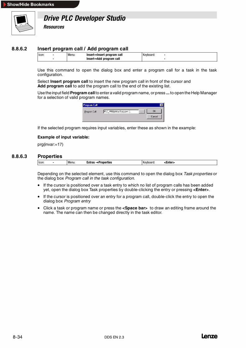
Drive PLC Developer StudioResources
8-34 lDDS EN 2.3
8.8.6.2 Insert program call / Add program callIcon: -
-Menu: Insert�Insert program call
Insert�Add program callKeyboard: -
-
Use this command to open the dialog box and enter a program call for a task in the taskconfiguration.
Select Insert program call to insert the new program call in front of the cursor andAdd program call to add the program call to the end of the existing list.
Use the input field Program call to enter avalid program name, or press ... to open the Help Managerfor a selection of valid program names.
If the selected program requires input variables, enter these as shown in the example:
Example of input variable:
prg(invar:=17)
8.8.6.3 PropertiesIcon: - Menu: Extras �Properties Keyboard: <Enter>
Depending on the selected element, use this command to open the dialog box Task properties orthe dialog box Program call in the task configuration.
• If the cursor is positioned over a task entry to which no list of program calls has been addedyet, open the dialog box Task properties by double-clicking the entry or pressing <Enter>.
• If the cursor is positioned over an entry for a program call, double-click the entry to open thedialog box Program entry
• Click a task or program name or press the <Space bar> to draw an editing frame around thename. The name can then be changed directly in the task editor.

Drive PLC Developer StudioResources
8-35l DDS EN 2.3
8.9 Watch and Receipt Manager
The Watch and Receipt Manager is an object on the tab Resources in theObject Organizer.
Use the Watch and Receipt Manager to
• display values of certain variables.
• pre-assign variables with certain values and transfer them to the control in one go.
• read and save current control values as pre-assignment in the Watch and Receipt Manager.
These functions assist in the generation and logging of control parameters, for example.
• The left-hand panel of the Watch and Receipt Manager displays all generated watch lists thatcan be selected with a click or using the arrow keys.
• The right-hand pane of the Watch and Receipt Manager displays the associated variables.
8.9.1 Watch and Receipt Manager in offline mode
In offline mode, it is possible to create several watch lists in the Watch and Receipt Manager usingInsert� New watch list .
The variables to be watched can be selected from a list of all variables called with the Help Manageror entered via the keyboard in accordance with the following notation:
<Organization unit name>.<Variable name>
• Global variables do not have an organization unit name, but start with a period.The variable name can be multi-level.
• Addresses can be entered directly.
Example of a multi-level variable:
PLC_PRG.Instance1.Instance2.Structure.Component name
Example of a global variable:
.global1.component1
Variables in the watch list can be pre-assigned constant values, i.e. in online mode, these values canbe written to the variables using the menu command Extras�Write receipt. For this purpose, theconstant value must be assigned to the variable with :=.
Example:
PLC_PRG.TIMER:=50

Drive PLC Developer StudioResources
8-36 lDDS EN 2.3
8.9.2 Watch and Receipt Manager in online mode
In online mode, the Watch and Receipt Manager displays the values of the entered variables.
• Structured values (arrays, structures and instances of function blocks) are identified with aplus sign in front of the identifier.Click on the plus sign to open the variable. A minus sign appears instead of the plus sign.Click on the minus sign to close the variable again.
• If a function block variable is selected in the watch list, the associated shortcut menu isextended by the two menu items Open function block and Open instance .
• To enter new variables, switch the display off using the commandExtras�Monitoring active. After the variables have been entered, the display can beactivated again with the same command.
• If constant values were assigned to variables in offline mode, these values can be written tothe variables using the command Extras�Write receipt.
• Extras�Read receipt replaces the pre-assignment of a variable with the current variablevalue.
8.9.3 Command overview
8.9.3.1 New watch listIcon: - Menu: Insert�New watch list Keyboard: -
Use this command to insert a new watch list in the Watch and Receipt Manager.
• Enter the required name of the watch list into the dialog box.
8.9.3.2 Rename watch listIcon: - Menu: Extras�Rename watch list Keyboard: -
Use this command to change the name of a watch list in the Watch and Receipt Manager.
• Enter the new name of the watch list into the dialog box.
8.9.3.3 Save watch listIcon: - Menu: Extras�Save watch list Keyboard: -
Use this command to save a watch list.
Selection of the command opens the dialog box Save as.
• Use the input field File name to enter a new file name.
• The extension ”*.wtc” is already specified in the input field Save as type.
The saved watch list can be reloaded with Extras����Load watch list

Drive PLC Developer StudioResources
8-37l DDS EN 2.3
8.9.3.4 Load watch listIcon: - Menu: Extras�Load watch list Keyboard: -
Use this command to load a saved watch list.
Selection of the command opens the dialog box Open.
• Select the required file with the extension ”*.wtc” and click OK.
Enter the new watch list name in the dialog box.
• The input field already displays the file name without extension.
Click Extras����Save watch list to save a watch list.
8.9.3.5 Monitoring activeIcon: - Menu: Extras�Monitoring active Keyboard: -
Use this command to switch the display of the Watch and Receipt Manager on and off in onlinemode.
• If the display is activated, a tick appears in front of the menu item.
The display must be switched off with this command to enter a new variable or to pre-assign a value.The display can be switched on again after the variable has been entered, executing the commandagain.
8.9.3.6 Write receiptIcon: - Menu: Extras�Write Receipt Keyboard: -
Use this command to write the pre-assigned values to the variables in the Watch and ReceiptManager’s online mode.
8.9.3.7 Read ReceiptIcon: - Menu: Extras�Read Receipt Keyboard: -
Use this command to replace the pre-assignment of the variables with the current values in theWatch and Receipt Manager’s online mode.
Example:
PLC_PRG.counter [:= <current value>] = <current value>
Tip!Only the values in the watch list selected in the Watch and Receipt Manager will be loaded!

Drive PLC Developer StudioResources
8-38 lDDS EN 2.3
8.10 Target Settings
The Target Settings are located as an object in the Resources index and
• define the target system on which the project is to run,
• define the project settings,
• require a target system to be selected after the menu command Project�New has beenexecuted.
The dialog box Target Settings opens automatically when a new project is generated and can alsobe requested from Resources�Target Settings.
Select a target system from the Configuration pull-down menu.
Tip!The Default button resets all entries in this dialog box to the initial state.
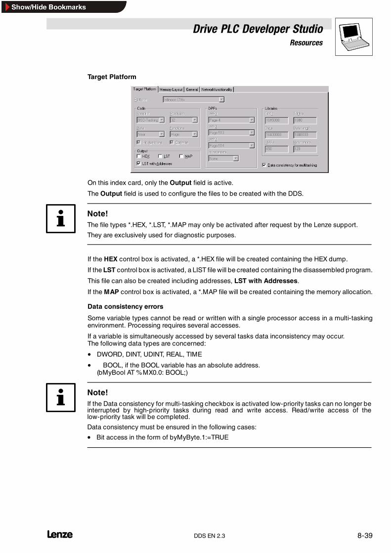
Drive PLC Developer StudioResources
8-39l DDS EN 2.3
Target Platform
On this index card, only the Output field is active.
The Output field is used to configure the files to be created with the DDS.
Note!The file types *.HEX, *.LST, *.MAP may only be activated after request by the Lenze support.
They are exclusively used for diagnostic purposes.
If the HEX control box is activated, a *.HEX file will be created containing the HEX dump.
If the LST control box is activated, a LIST file will be created containing the disassembled program.
This file can also be created including addresses, LST with Addresses.
If the MAP control box is activated, a *.MAP file will be created containing the memory allocation.
Data consistency errors
Some variable types cannot be read or written with a single processor access in a multi-taskingenvironment. Processing requires several accesses.
If a variable is simultaneously accessed by several tasks data inconsistency may occur.The following data types are concerned:
• DWORD, DINT, UDINT, REAL, TIME
• � BOOL, if the BOOL variable has an absolute address.(bMyBool AT %MX0.0: BOOL;)
Note!If the Data consistency for multi-tasking checkbox is activated low-priority tasks can no longer beinterrupted by high-priority tasks during read and write access. Read/write access of thelow-priority task will be completed.
Data consistency must be ensured in the following cases:
• Bit access in the form of byMyByte.1:=TRUE

Drive PLC Developer StudioResources
8-40 lDDS EN 2.3
Use of older versions
Note!The following restrictions or behaviour can occur when older program versions or projects areused.
• If DDS 2.2 is used for the compilation of projects that were created with DDS 2.1 or 2.0 theruntime may change and a task overflow may occur when the Data consistency formulti-tasking checkbox is activated.
• If projects that were created with DDS 2.2 are opened with DDS 2.1 or 2.0 data consistencyfor multi-tasking is not supported. Data consistency and runtime errors may occur during thecompilation with DDS 2.1 or 2.0.
Memory Layout
The index card is not editable.
General
Address checking is active by default so that the project can only use absolute addresses that havebeen entered in the PLC configuration.
The control box No address checking deactivates the address checking. When compiling theproject, the IEC addresses will not be checked.
Network functionality
The index card is not active.

Drive PLC Developer StudioResources
8-41l DDS EN 2.3
8.11 Library Manager
In the DDS, libraries are managed with the Library Manager that can be activated with the commandWindow����Library Manager.
• Information about the linked libraries is stored with the project.
• The Library Manager shows all libraries available for the current project.
• Organization units, data types, visualizations and global variables of the libraries can be usedlike user-defined organization units, data types, visualizations and global variables.
8.11.1 Library Manager window
The Library Manager window is split into three or four panes.
Libraries
The upper left-hand pane shows the libraries available for the project.
Organization units/data types/visualizations/global variables
Depending on the selected tab, the lower left-hand pane lists the organization units, data types,visualizations or global variables of the library selected in the upper pane.
• Folders are opened or closed with a double-click or by pressing <Enter>.
• A plus sign in front of the closed folder icon indicates that this folder contains objects and/orother folders.
A click on the plus sign opens the folder and shows all subordinate objects.A minus sign now replaces the plus sign.
A click on the minus sign closes the folder again.
Declaration / graphic representation of an organization unit
If an organization unit is selected by mouse click or arrow keys, the upper right-hand pane of theLibrary Manager will display the declaration of the organization unit, and the lower right-hand panethe graphic representation as black box with inputs and outputs.

Drive PLC Developer StudioResources
8-42 lDDS EN 2.3
Declaration of data types/global variables
The declaration of data types and global variables is displayed in the right-hand pane of the LibraryManager.
Declaration of visualizations
For visualizations, the right-hand pane shows the used placeholders and the visualization.
8.11.1.1 Insert libraryIcon: - Menu: Insert�Additional Libraries Keyboard: <insert>
Use this command to link another library to your project.
Selection of the command opens the dialog box Open.
• Select the required file (extension ”*.lib”) and click OK.
The library is now listed in the Library Manager, and the objects of the library can be used likeuser-defined objects.
Tip!This command is also available via the shortcut menu (right mouse key) in the top left-hand paneof the Library Manager.
8.11.1.2 PropertiesIcon: - Menu: Extras �Properties Keyboard: <Alt>+<Enter>
Use this command to obtain information on the selected library.

Drive PLC Developer StudioResources
8-43l DDS EN 2.3
8.11.2 Included libraries
The DDS comes with the following libraries, among others:
Tip!For a detailed description of the function blocks refer to the manual for the associated functionlibrary and the Online Help.
IEC 61131-3 standard library ”Standard.lib”
The library Standard.lib contains all functions and function blocks required by IEC 61131-3 asstandard organization blocks for an IEC programming system.
The difference between a standard function and an operator is that the operator is implicitly knownto the programming system whereas the standard organization units must be linked to the projectas library (standard.lib).
Library ”LenzeDrive.lib”
The library LenzeDrive.lib includes function blocks to implement standard drive tasks for 9300Servo PLC, Drive PLC and Servo Axis Module ECSxA.
• Multiple instancing of these function blocks as per IEC 61131-3 is possible.
Library ”LenzeElectricalShaft.lib”
The library LenzeElectricalShaft.lib contains special function blocks for the ”electrical shaft” .
Library ”Lenze9300Servo.lib”
The library Lenze9300Servo.lib contains special function blocks for the 9300 Servo PLC and ServoAxis Module ECSxA.
Library ”lecsfc.lib” for IEC steps in SFC
The library lecsfc.lib contains IEC steps to be used in the Sequential Function Chart.
8.11.3 User-defined libraries
A complete and correctly compiled project can be saved under File����Save as as internal library(*.lib), external library (*.lib) or as project (*.pro).
• The project itself will not be changed.
• After the save, it will be available as the standard library under the specified name.
Saving the library removes the organization unit PLC-PRG from the project.
Note!Saving the library removes the organization unit PLC-PRG from the project.

Drive PLC Developer StudioResources
8-44 LDDS EN 2.3

Drive PLC Developer StudioVisualization
9-1l DDS EN 2.3
9 VisualizationVisualization is located on the tab Visualization in the Object Organizer .
Use visualization to draw geometrical elements in offline mode to change their shape or colour inonline mode depending on certain variable values.
Tip!Use the menu command Project ����Insert object to create a new visualization object.
Placeholders allow a visualization object to be used more than once. A visualization object can beinserted into other visualizationobjects. Replacing the placeholders assigns different configurationsto the visualization object.Visualization objects inserted into other visualizations are called references. There are two optionsto configure a visualization object.
Depending on the configuration, a reference responds differently to actions in online mode.
• The individual elements of the reference respond like the original visualization.
• The individual elements of the reference remain unconsidered. The reference responds toinputs as an overall object.
Application examples:
• Have the behaviour of a variable displayed during growth in a bar graph.
• Program entries via mouse and keyboard.
If an appropriate translation file is available, texts can be displayed in a different language duringonline visualization.Project �Translate into other languages (� 6-12)

Drive PLC Developer StudioVisualization
9-2 lDDS EN 2.3
9.1 Inserting visualization elements
Insertion mode
If the visualization level is active, the menu command Insert lists the various different visualizationobjects.
• The mouse pointer in the editor window turns to the icon of the element to be inserted.
• The status bar displays the name of the element to be inserted in black.
• After an element has been inserted, the process automatically changes to selection mode.
Selection mode
In selection mode, one or several elements can be selected for editing.
• To insert another element, change back to insertion mode with the right mouse button whilekeeping the <Ctrl> key depressed, or reselecting the associated insert command.
Tip!Toggle between insertion and selection modes with the right mouse key while keeping the <Ctrl>key depressed.
9.1.1 Commands in the “Insert” menu
9.1.1.1 RectangleIcon: Menu: Insert �Rectangle Keyboard: -
Use this command to insert a rectangle as an element into your current visualization.
Command selection turns the mouse pointer into the associated icon in the editor window.
• Use the depressed left mouse key to size the element as required in the editor window.
9.1.1.2 Rounded rectangleIcon: Menu: Insert �Rounded rectangle Keyboard: -
Use this command to insert a rounded-corner rectangle as an element into your currentvisualization.
Command selection turns the mouse pointer into the associated icon in the editor window.
• Use the depressed left mouse key to size the element as required in the editor window.
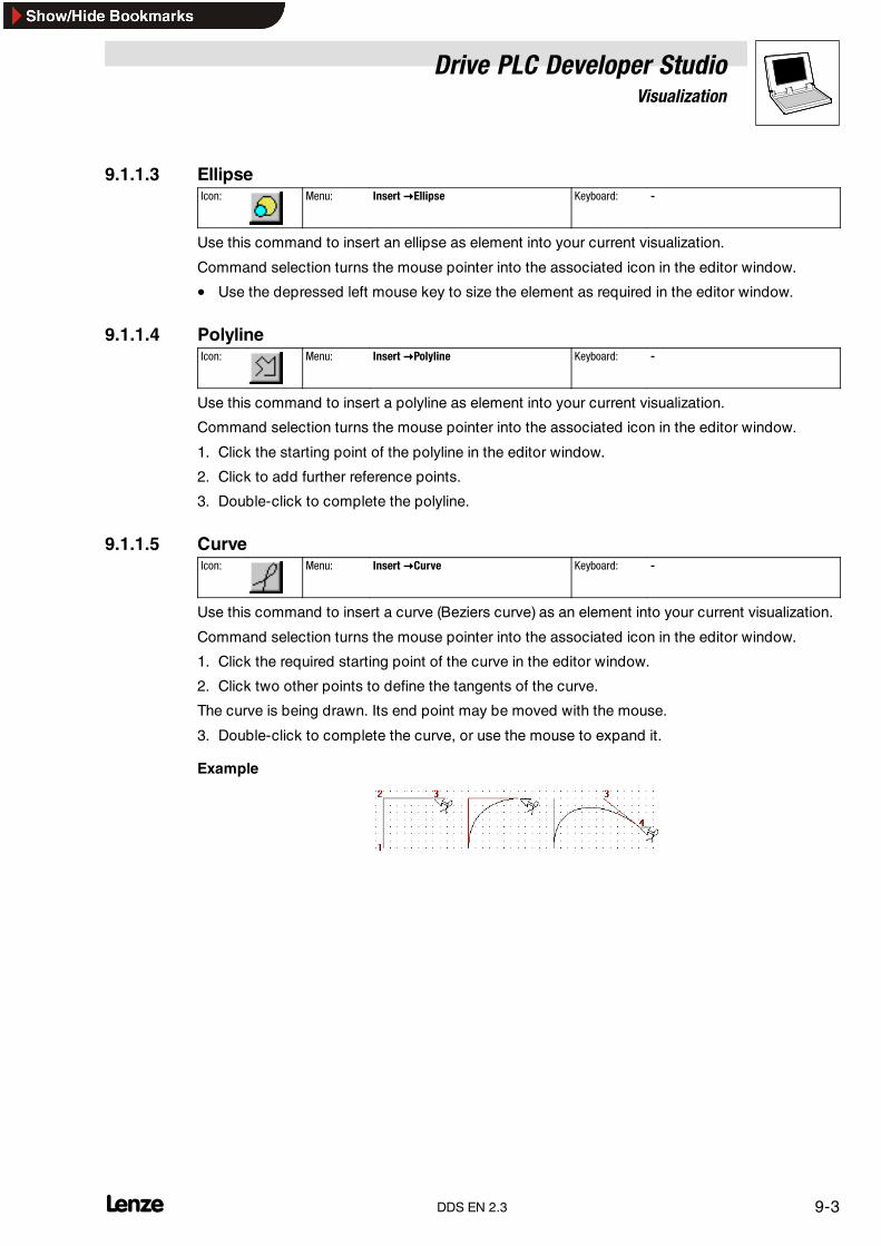
Drive PLC Developer StudioVisualization
9-3l DDS EN 2.3
9.1.1.3 EllipseIcon: Menu: Insert �Ellipse Keyboard: -
Use this command to insert an ellipse as element into your current visualization.
Command selection turns the mouse pointer into the associated icon in the editor window.
• Use the depressed left mouse key to size the element as required in the editor window.
9.1.1.4 PolylineIcon: Menu: Insert �Polyline Keyboard: -
Use this command to insert a polyline as element into your current visualization.
Command selection turns the mouse pointer into the associated icon in the editor window.
1. Click the starting point of the polyline in the editor window.
2. Click to add further reference points.
3. Double-click to complete the polyline.
9.1.1.5 CurveIcon: Menu: Insert �Curve Keyboard: -
Use this command to insert a curve (Beziers curve) as an element into your current visualization.
Command selection turns the mouse pointer into the associated icon in the editor window.
1. Click the required starting point of the curve in the editor window.
2. Click two other points to define the tangents of the curve.
The curve is being drawn. Its end point may be moved with the mouse.
3. Double-click to complete the curve, or use the mouse to expand it.
Example

Drive PLC Developer StudioVisualization
9-4 lDDS EN 2.3
9.1.1.6 PolygonIcon: Menu: Insert �Polygon Keyboard: -
Use this command to insert a polygon as an element into your current visualization.
Command selection turns the mouse pointer into the associated icon in the editor window.
1. Click the required starting point of the polygon in the editor window.
2. Click to add further reference points.
3. Double-click to complete the polygon.
9.1.1.7 BitmapIcon: Menu: Insert �Bitmap Keyboard: -
Use this command to insert a graphic that must be in a bitmap (.bmp) or tagged image file format(.tif) as an element into your current visualization.
Command selection turns the mouse pointer into the associated icon in the editor window.
1. In the editor window, mark the area for the graphic, keeping the left mouse key depressed.
2. Select the graphic file to be inserted from the dialog box Open .
9.1.1.8 VisualizationIcon: Menu: Insert �Visualization Keyboard: -
Use this command to insert an existing visualization into your current visualization.
Command selection turns the mouse pointer into the associated icon in the editor window. Aninserted visualization is called a reference.
1. In the editor window, mark the area for the visualization, keeping the left mouse keydepressed.
2. In the dialog box Select visualization , select the visualization to be inserted.
9.1.1.9 Button
Icon: Menu: Insert �Button Keyboard: -
Use this command to insert a blank button into your current visualization.The button will visualize any toggle variables configured for a button.
1. Size the element as required, keeping the left mouse key depressed.
2. The generated button can later be formatted with the menu command Extras -> Configure .
Drive PLC Developer StudioVisualization
9-5l DDS EN 2.3
9.2 Editing visualization elements
9.2.1 Information in the status bar
The status bar contains the following information for visualization:
X /Y position
The current X and Y position of the mouse pointer is displayed in pixels relative to the top left-handcorner of the image.
Element number
If the mouse pointer is positioned over an element or if an element is edited, the number of theelement will be displayed.
Insertion mode
If the insertion mode is active, the name of the element to be inserted will be displayed.
9.2.2 Expressions
The following inputs are possible if PLC variables are effective in the configuration of a visualizationobject.
• Variable name with Help Manager
• Composite expressions consisting of– component accesses (e. g. STRUCT)– field accesses ( ARRAYaccess) with constant index– variables and direct addresses
• Operators and addresses that can be combined with the named expressions.
Examples of permissible expressions
x+y
100*PLC_PRG.a
TRUE
NOT PLC_PRG.b
q*sin(x+100)+cos(y+100)
The following inputs are not possible.
• Function callsImpermissible expressions lead to an error message during log-in(incorrect Watch expression)

Drive PLC Developer StudioVisualization
9-6 lDDS EN 2.3
Examples of impermissible expressions
fun(88)
a:=9
RETURN
Global variables can be written in two ways.
.globvar (not possible within a composite expression
globvar
9.2.3 Selecting visualization elements
Tip!The commands for editing elements always refer to the element(s) currently selected.
Selecting one element
• Click the element to be selected.
• Pressing the <Tab>key also causes a jump to the first element in the element list. Press thekey again to jump to the next element. Using the <Tab>key while keeping the<Umschalt>key depressed causes the system to jump in the opposite direction in theelement list.
Selecting several elements
• Keep the <Umschalt> key depressed and click the associated elements one after the other.
or
• keep the left mouse key depressed to draw a window across the elements to be selected.
Selecting all elements
• Use the command Extras����Select all to select all elements of the visualization.
Processing from element list
• Use the command Extras����Element list to open the element list.
• This list includes the type and location of all generated elements. Use the button Edit to editany selected element.
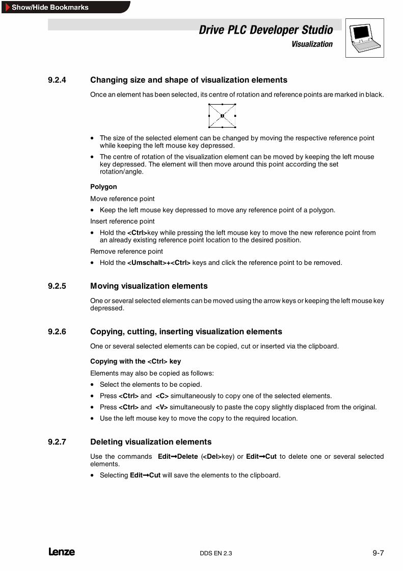
Drive PLC Developer StudioVisualization
9-7l DDS EN 2.3
9.2.4 Changing size and shape of visualization elements
Once an element has been selected, its centre of rotation and reference points are marked in black.
• The size of the selected element can be changed by moving the respective reference pointwhile keeping the left mouse key depressed.
• The centre of rotation of the visualization element can be moved by keeping the left mousekey depressed. The element will then move around this point according the setrotation/angle.
Polygon
Move reference point
• Keep the left mouse key depressed to move any reference point of a polygon.
Insert reference point
• Hold the <Ctrl>key while pressing the left mouse key to move the new reference point froman already existing reference point location to the desired position.
Remove reference point
• Hold the <Umschalt>+<Ctrl> keys and click the reference point to be removed.
9.2.5 Moving visualization elements
One or several selected elements can be moved using the arrow keys or keeping the left mouse keydepressed.
9.2.6 Copying, cutting, inserting visualization elements
One or several selected elements can be copied, cut or inserted via the clipboard.
Copying with the <Ctrl> key
Elements may also be copied as follows:
• Select the elements to be copied.
• Press <Ctrl> and <C> simultaneously to copy one of the selected elements.
• Press <Ctrl> and <V> simultaneously to paste the copy slightly displaced from the original.
• Use the left mouse key to move the copy to the required location.
9.2.7 Deleting visualization elements
Use the commands Edit����Delete (<Del>key) or Edit����Cut to delete one or several selectedelements.
• Selecting Edit����Cut will save the elements to the clipboard.

Drive PLC Developer StudioVisualization
9-8 lDDS EN 2.3
9.2.8 Commands in the “Extras” menu
9.2.8.1 Element listIcon: - Menu: Extras �Element list Keyboard: -
Use this command to open the dialog box Element list that lists all visualization elements with theirnumber, type and position.
• The position refers to the X and Y position of the top left- and bottom right-hand corner of theelement.
• Once one or several elements has/have been selected, the respective elements will behighlighted in the visualization for a visual check, and the display may scroll to the sectionwith the selected elements as required.
Buttons
• Use To the foreground to display the selected visualization elements in the foreground.
• Use To the background to move the selected visualization elements to the background.
• Use Delete to delete the selected visualization elements.
• Use Undo and Redo to undo and redo actions carried out before. These commands areanalogous to Edit����Undo and Edit����Redo. The editor window will display any changes.
• Click OK to confirm the changes and close the dialog box.
9.2.8.2 To the foregroundIcon: - Menu: Extras �To the foreground Keyboard: -
Use this command to bring the selected visualization elements to the front.
9.2.8.3 To the backgroundIcon: - Menu: Extras �To the background Keyboard: -
Use this command to send the selected visualization elements to the back.
9.2.8.4 AlignIcon: - Menu: Extras �Align Keyboard: -
Use this command to align several selected visualization elements.
The following alignment options are available:
Left All elements are aligned with their left-hand edge with the element on the extreme left.
Right / top / bottom Alignment analogous to Left.
Horizontal middle All elements are aligned by their horizontal centre within the centre of all elements.
Vertical middle All elements are aligned by their vertical centre within the centre of all elements.
9.2.8.5 Select allIcon: - Menu: Extras �Select all Keyboard: -
Use this command to select all visualization elements of the current visualization object.

Drive PLC Developer StudioVisualization
9-9l DDS EN 2.3
9.2.8.6 Placeholder list
Icon: - Menu: Extras �Placeholder list Keyboard: -
Every point of the configuration dialog Extras�Configurethat allows variables or text to be input,also offers the possibility of entering a placeholder instead of the variables or the text.
This is appropriate if the visualization object is to be integrated into other visualization objects as areference. On calling the respective reference, the placeholder can then be substituted accordinglywith the variable or text.
The dialog shows the placeholders used in the current visualization object and allows a preliminarydefinition. The input focus must be on the visualization object.
On reference configuration, each placeholder can be substituted with the associated values.
Placeholders
This column lists the placeholders available for visualization.
Element numbers
Displays the number of the element for which the placeholder was generated. Also compare theelement list numbers.
Replacements
This option allows the input of a selection of strings which the placeholder substitutes. Theplaceholder is the reference to the string. The strings must be comma-separated. Where no entryexists, the placeholder can be substituted with any text during reference configuration.
Possible replacements
Placeholder Element number Replacements
text 0 box_a, box_b
Change colour 0 pic_prg.var, var_changecolour1, pic_prg.var_changecolour2
text2 1 a, b, c, d
togglevar 0

Drive PLC Developer StudioVisualization
9-10 lDDS EN 2.3
9.3 Configuring visualization elements
9.3.1 Commands in the “Extras” menu
9.3.1.1 SettingsIcon: - Menu: Extras �Settings Keyboard: -
Use this command to open the dialog box Visualization settings for the following settings:
Category View
• Text field Zoom permits a zoom factor from 10 to 500 %.
• If check box Element numbers is activated, the element number will be displayed for everyelement in offline mode.
Category Frame
• If check box Auto scrolling is activated, the visible area of the visualization window will bemoved automatically when drawing or moving a visualization element when the window” frame” is reached.
• If check box Automatic adaptation online is activated, the visualization is adapted to thewindow size (all elements visible) in online mode.
• If check box Include background bitmap is activated, a ticked check box Automaticadaptation online means that the size of the bitmap is also considered when adapting thevisualization to the window; otherwise only the elements will be considered.
Category Grid
• If check box Visible is activated, the pixels will be displayed in offline mode.
• If check box Active is activated, elements can only be positioned onto pixels during drawingand moving processes.
• Text field Size defines the spacing between pixels.
Tip!The spacing between visible pixels is at least 10 pixels, even if the text field Size specifies less.
At a lower-than-10 spacing, the pixels will still appear at a 10-pixel spacing.
Category Language
• If check box Language file is active, a special language file *.vis can be generated.
• Use the button ... to open a dialog to save the language file.
• The combination box Language allows language selection.
• The button Save stores the language file at the selected location.
• Use the button OK to save the dialog box settings.

Drive PLC Developer StudioVisualization
9-11l DDS EN 2.3
Creating a language file
• Tick check box Language file. The group box Language is active.
• In the combination box Language enter ”en” , for example (English).
• Enter a path or use ... to look for the directory in which the language file is to be saved. Thefile name, English.vis, for example, must be specified at the end.
• Press Save once the dialog box fields have all been completed. In the example, the fileEnglish.vis will be generated in the specified target path.
The created language file can be opened with a text editor.
9.3.1.2 Select background bitmapIcon: - Menu: Extras�Select background bitmap Keyboard: -
Use this command to load a bitmap as background for the visualization.
Selection of the command opens the dialog box Open file.
• Select the required file with the extension (”*.bmp”) and click OK.
The selected bitmap appears in the background of the visualization.
9.3.1.3 Delete background bitmapIcon: - Menu: Extras�Delete background bitmap Keyboard: -
Use this command to delete the background bitmap of the current visualization.
9.3.1.4 ConfigureIcon: - Menu: Extras�Configure Keyboard: -
Use this command to open the dialog box Configure element to configure the selected visualizationelement.
Tip!The dialog box can also be opened by double-clicking an element.
Configure�Form available for: rectangle, rounded rectangle, ellipse
Use Extras����Configure, category Form to assign the shape Rectangle, Rounded rectangle orEllipse to the selected element.
• The defined size remains unaffected.
Configure�Text available for: all
Use Extras����Configure, category Text to assign a text to the selected element. This text will beentered directly or substituted by a placeholder.
Contents
Use the input field Contents for text entry.<Ctrl>+<Return> generates a line break<Ctrl>+<Tab> generates tab stops
• An entry of ”%s” means that this text is substituted in online mode by the value of the variablefrom text field Text output in the category Variables.

Drive PLC Developer StudioVisualization
9-12 lDDS EN 2.3
Caution!If a translation file is to allow a switch into another national language in online mode, the specific textmust be framed by #Text#.
#Pump 1# or #Pump# 1If the text Pump (Pump1, Pump2 etc.) occurs several times, the second case will save severaloccurrences in the translation.
Horizontal/vertical
Selecting the respective check box defines the layout of the configured text within the element.
Font
Click Font to open the dialog box Font and select the font for the text.
Standard font
Click Standard font to use the font selected under Project����Options.
• If the font is changed under Project����Options, this change will affect all elements that werenot explicitly assigned another font via button Font.
Configure�Line width available for: all
Use Extras����Configure, category Line width to modify the line widths of the selected objects.
Configure�Colours available for: rectangle, rounded rectangle, ellipse
Use Extras����Configure, category Colours to assign original colours and signal colours for fill andframe to the selected element.
• If a Boolean variable is entered under category Variables, field Change colour, the elementwill be displayed in the set colour as long as the variable is FALSE. If the variable is TRUE, theelement will be displayed in signal colour.
Tip!The Change colour function is active only if the control is in online mode or simulation!
• Click Inside or Frame to open the dialog box Colours and select the associated colour.
Configure�Motion absolute available for: all
Use Extras����Configure, category Motion absolute to define amotion dependent on variablevaluesfor the selected element.
Tip!To enter variables, use the Help Manager <F2>
X offset/Y offset
Use the input fields X offset/Y offset to enter variables whose values effect motion of the elementin X or Y direction.

Drive PLC Developer StudioVisualization
9-13l DDS EN 2.3
Scaling
Use the input field Scaling to enter a variable to define the size of the element.
Input and effect
Magnification
1000 1:1 no change
100 x 0.1
10000 x 10
Angle
Use the input field Angle to enter a variable whose value causes element rotation (positive value =mathematically positive = CW rotation).
• The value is evaluated in degrees.
• The centre of rotation of a selected element can be moved, keeping the left mouse keydepressed.
A variable in field Angle causes the current element to rotate. The rotation is brought about bypositive values and follows a CW direction.
Configure�Motion relative available for: all except polygon
Use Extras����Configure, category Motion relative to assign variables to the edges of the selectedelement. The respective element edges move according to the variable values.
Tip!To enter variables, use the Help Manager <F2>.
Every side of the element has its own input field.
• The normal edge position is zero, a new variable value in the associated column moves theborder by this value in pixels. The entered variables should be variables of type INT.
• Positive values move the horizontal edges downward or the vertical edges to the right!
Configure�Variables available for: all
Use Extras����Configure, category Variables to define variables to describe the status of theselected element.
Tip!To enter variables, use the Help Manager <F2>.
Invisible
If the variable in the input field Invisible is set to FALSE, the visualization element will be visible. Ifthe variable is TRUE, the element will be invisible.
Change colour
If the variable in the input field Change colour is set to FALSE, the visualization element will bedisplayed in its original colour. If the variable isTRUE, the element will bedisplayed in its signal colour.
Text display
Use the input field Text display to enter a variable whose value will be output if the field Contentin the category Text contains ”%s” in addition to the text.

Drive PLC Developer StudioVisualization
9-14 lDDS EN 2.3
9.3.2 Formatted text display
The following tables provide a general formatted text display.
Char format
Element Meaning
% Formatted text display starts with %. If the character is to be included in the display for specific reasons, the first charactersmust be %%.
- Display is left-aligned.
b Display field minimum width
c For Char variables
String format
Element Meaning
% Formatted text display starts with %. If the character is to be included in the display for specific reasons, the first charactersmust be %%.
- Display is left-aligned.
b Display field minimum width
.n Width of the field section written by the string
s For Char arrays
Integer format
Element Meaning
% Formatted text display starts with %. If the character is to be included in the display for specific reasons, the first charactersmust be %%.
- Display is left-aligned.
+ Positive polarity
b Display field minimum width
.n Minimum number of display digits
Only one of the characters listed below appears at the end of the formatted text
d For Int variables
ld For long Int variables
Format for polarity-free integers
Element Meaning
% Formatted text display starts with %. If the character is to be included in the display for specific reasons, the first charactersmust be %%.
- Display is left-aligned.
# Leading zero for hexadecimal and octal representation
b Display field minimum width
.n Minimum number of display digits
Only one of the characters listed below appears at the end of the formatted text
d Number in decimal 0-9
x Number in hexadecimal 0-9 and a-f
X Number in hexadecimal 0-9 and A-F
o Octal 0-7 for polarity-free variables

Drive PLC Developer StudioVisualization
9-15l DDS EN 2.3
Format for floating-point numbers
Element Meaning
% Formatted text display starts with %. If the character is to be included in the display for specific reasons, the first charactersmust be %%.
- Display is left-aligned.
+ Positive polarity
# Leading zero for hexadecimal and octal representation
b Display field minimum width
.n Digits after the point, preset: 6
Only one of the characters listed below appears at the end of the formatted text
lf For double variables ddd.dddddd
f For float variables ddd.dddddd
e d.ddddddefdd
E d.ddddddE±dd
g Like f or e in shorter representation
G Like F or E in shorter representation
Program example
The following program example illustrates how a Formatted number output is represented in theDDS.
• Variables are declared and instructions written in the first step.
• Then visualization is established with the help of two rectangles. Element 0 is to be configuredas follows. For element 1, the only input needs to be made in category Variables in Textdisplay: text.ftext2.
• The input in category Text, input field Content consists of the Formatted number display..The preset inputs should be accepted first.

Drive PLC Developer StudioVisualization
9-16 lDDS EN 2.3
• The display then is as follows in online mode. The previously made inputs return therepresentation below.
To test the effect of the Formatted number display, enter other formats as well with %.
• ”%s” will be substituted in online mode with the value of the variable entered in the input fieldText display.
Configure�Input available for: all
Use Extras����Configure, category Input to define whether the online mode should allow mouse andkeyboard inputs or not.
Toggle variable
If check box Toggle variable is activated, every mouse click will toggle the value of the Booleanvariable entered in the input field behind.
• Every mouse click on the visualization element will toggle the value of the Boolean variablefrom TRUE to FALSE or from FALSE to TRUE.
Tip variable
If check box Tip variable is activated, the value of the Boolean variable specified in the input fieldbehind will be changed by pressing the left mouse key and keeping it depressed.
• The value of the Boolean variable will change from TRUE to FALSE or fromFALSE toTRUEwhen positioning the mouse pointer over the visualization element, then pressing the leftmouse key and keeping it depressed.
• The value of the Boolean variable will return to its original status on releasing the left mousekey.
• If check box Tip FALSE is active, the value - on clicking OK - will change from TRUE toFALSE.
Caution!This function cannot always be guaranteed to be reliable. Do not use Tip variable for safety-relevantdrive control functions (such as positioning, for example).

Drive PLC Developer StudioVisualization
9-17l DDS EN 2.3
Zoom to Vis
If check box Zoom to Vis is activated, a mouse click on the visualization element will take you tothe window of the visualization selected in the input field.
• Activating check box Toggle variable as well will toggle the variable specified in text fieldToggle variable.
• If a STRING-type program variable (e. g. PLC_PRG.xxx) is specified in the text fieldinstead of the visualization, this variable may be used to preset the name of the visualization(e. g. xxx:=’visu1’).
• If the text field Zoom to Vis is used to enter command ZOOMTOCALLER, the online modeprovides for a return to the calling visualization by clicking the element, if such a constellationhas been configured.
If a jump is to be executed to a visualization reference with placeholders, these may be substituteddirectly on call with variable names or texts.
Observe the following syntax.
<Visuname>(<Placeholder1>:=<Text1>,<Placeholder2>:=<Text2>,...,<Placeholdern>:=<Textn>)
Call for visualization visu1, where the placeholders used in visu1$var_ref1$and$var_ref2$ are substituted with variables PLC_PRG.var1 or PROG.var1.
visu1(var_ref1:=PLC_PRG.var1, var_ref2:=PROG.var1)
Execute program
If check box Execute program is activated, the executable program specified in the input field willbe launched on clicking the visualization element.
Example
notepad C:/help.txt (the program Notepad will be started and the file help.txt opened).
Text input of variable ’Text display’
If check box Text input of variable ’Text display’ is activated, a value can be assigned to avariableby clicking the visualization element.
• The value is assigned to the variable selected in category Variables in the text field Textdisplay.
• Clicking the visualization element will display an input field for the new variable value. Press<Enter> to accept the value.
Configure�Text for tool tip available for: all
Use Extras����Configure, category Text for tool tip to enter a text for the selected element. This textis displayed when the mouse pointer is positioned briefly over the element.
• Line breaks in the text can be entered by pressing <Ctrl>+<Enter>.

Drive PLC Developer StudioVisualization
9-18 lDDS EN 2.3
Configure�Bitmap available for: Bitmap
Use Extras����Configure, category Bitmap to effect settings for the selected bitmap.
Bitmap
Use the input field Bitmap to enter the bitmap file and its path.
• Click ... to open the standard dialog for browsing through the file structure to select therequired file.
• Use check box Transparent background to define a colour contained in the bitmap astransparent. Use the button Transparent colour to define the colour.
Frame
• If check box Anisotropic is activated, the bitmap fills its frame and its size can be changed.
• If check box Isotropic is activated, the proportions of the bitmap always remain the sameeven if the size changes, i.e. the ratio between length and width remains the same.
• If check box Fixed is activated, the bitmap will be displayed in its original size, independentof its frame.
• If check box Cut off is activated, the setting Fixed only displays the framed part of thebitmap.
• If check box Draw is activated, the frame will be displayed in the colour selected underColour and Signal colour. The signal colour will only be displayed if the variable entered inthe category Variables, field Change colour is TRUE.
Configure�Visualization available for: visualization
Use Extras����Configure, category Visualization to effect the settings for a visualization inserted intothe current visualization as an element. After insertion, this one is referred to as the Reference ofthe original one.
Visualization
Use the input field Visualization to enter the object name of the visualization.
• All visualizations except the current visualization and a reference to the current one can bespecified.
• Click ... to open the dialog box Select visualization to see a list of all visualizations availablefor this project.
Frame
• If check box Draw is activated, the frame will be displayed in the colour selected underColour and Signal colour . The signal colour will only be displayed if the variable entered inthe category Variables , field Change colour is TRUE.
• If check box Isotropic is activated, the proportions of the visualization always remain thesame even if the size changes, i.e. the ratio between length and width remains the same.
• If check box Cut off is activated, only the original section of the visualization will be displayedin online mode. If an object reaches beyond the original display, for example, this object willbe cut off and may not be visible any more.

Drive PLC Developer StudioVisualization
9-19l DDS EN 2.3
• Button Replace placeholder opens dialog box Replace placeholder. All placeholders used inthe inserted visualization organization unit will be listed. Column Replacements offers theoption of replacing these with a specific value.The available substitutes are dependent on whether dialog box Placeholder list predefines avalue set. The selection is displayed in a combination box. Where no predefinition has beenmade, a double-click on the associated field in the column Substitutes will open theplaceholder in an edit field where it can be completed as required.
• Another option to substitute placeholders in references is directly on a visualization call via anentry in text field Zoom to Vis:, category Input of the configuration dialog for a visualizationelement.
Caution!The chronological substitution sequence can not be influenced! No placeholders should besubstituted with texts that include placeholders themselves!
The use of placeholders makes it impossible to check any invalid entries in the configuration of thevisualization elements at the time of project compilation, so that any relevant error messages willbe output in online mode only (” ...incorrect Watch expression...”).
Placeholder concept
Example for using the placeholder concept
Function block instances can be easily displayed with references of the same visualisation.
When configuring visualisation elements, placeholders enable the visualisation objects to be usedseveral times.
If a visualisation object created with placeholders is inserted into another visualisation, theplacehol-ders are replaced by variables or strings.
Besides organisation units and global variables visualisation objects can also be stored in libraries.The use of placeholders enable the instances of the organisation unit to be referenced within the li-brary.
Caution!If after a visualization has been inserted, this reference is selected and configured, it will beconsidered object and respond as such to inputs in online mode in accordance with itsconfiguration. If no configuration input is made for the referenceat thepoint of insertion, its individualelements will respond like those of the original visualization in online mode.
Visualisation object with placeholders
• Declare the following function block in ST.
PROGRAM PLC_PRG
VAR
nVar10:INT:=10;
nVar20:INT:=20;
END_VAR

Drive PLC Developer StudioVisualization
9-20 lDDS EN 2.3
• A semicolon ” ;” must be entered into the instruction part.
• Create a new visualisation with the name Screen1 and insert a rectangle withInsert�Rectangle.
• Mark the rectangle and open the configuration dialog with Extras�Configure.In the category Text, input field content, enter the ”variable value” . The other options remainunchanged.
• In the category Variables, input field Textdisplay, enter ”$Ref$” . Placeholders are enclosedby the $ signs. The signs must be represented.
• Confirm the dialog with OK.
• Re-mark the rectangle. Open the dialog box Placeholder: set possible replacements withExtras�List of Placeholders complete the dialog box, and confirm with OK.
Placeholder Elementnumber Replacements
Ref 0 PLC_PRG.nVar10,PLC_PRG.nVar20
• Create another visualisation with the name Screen2.
• The visualisation Screen2 must be active. Insert a visualisation reference. Execute the menucommand Insert�Visualisation and draw a rectangle in the visualisation Screen2. The dialogbox Select Visualization is displayed Select Screen1 and confirm with OK.
• Mark the entire reference and open the configuration dialog. In the category Visualization(Screen1) press the button Placeholder. Select PLC_PRG.nVar20. from the replacementsand confirm with OK.
• In the category Visualization (Screen1) only mark the control boxes Isotropic and Clip andconfirm with OK.
• Store the program with a suitable name and log in.
9.3.2.1 GroupIcon: - Menu: Extras�Group Keyboard: -
Tip!Group allows several elements to be moved simultaneously without affecting the distancesin-between.
How to group
• Select the elements to be grouped.
• Select Extras�Group.
• Edit group (move, delete).
• Once the elements have been edited completely, the conglomerate can be ungrouped withExtras�Break up group.

Drive PLC Developer StudioVisualization
9-21l DDS EN 2.3
9.4 Visualization in libraries
Visualizations can also be saved in libraries and thus be made available as library organization unitsin projects.
• Like the visualizations available in the project directly, they can be inserted as references.
• Use the command Zoom to Vis to open another visualization.
Tip!The visualizations within a project must be uniquely named. Referenced and existing visualizationsmust bear uniquely different names.
Program execution first processes the visualizations within the project, and then thoseof the loadedlibraries.

Drive PLC Developer StudioVisualization
9-22 LDDS EN 2.3

Drive PLC Developer StudioIEC 61131-3 Data types
10-1l DDS EN 2.3
10 IEC 61131-3 data types
10.1 Standard data types
Standard or user-defined data types may be used for programming. Each identifier is assigned toa data type to define how much memory is to be reserved and which values correspond to thememory contents.
Standard data types are:
• BOOL
• Integer data types(BYTE, WORD, DWORD, SINT, USINT, INT, UINT, DINT, UDINT)
• REAL
• STRING
• Time data types(TIME, TIME_OF_DAY, DATE, DATE_AND_TIME)
10.1.1 BOOL
Variables of type BOOL can be TRUE or FALSE and are subject to an 8-bit memory reservation.
10.1.2 Integer data types
Integer data types include BYTE, WORD, DWORD, SINT, USINT, INT, UINT, DINT, UDINT.
Different data types cover different numerical ranges. The following range limits apply to integer datatypes:
Type Lower limit Upper limit Memory
Byte 0 255 8 bits
Word 0 65535 16 bits
DWORD 0 4294967295 32 bits
SINT -128 127 8 bits
USINT 0 255 8 bits
INT -32768 32767 16 bits
UINT 0 65535 16 bits
DINT -2147483648 2147483647 32 bits
UDINT 0 4294967295 32 bits
As a result, information may be lost when converting higher-order types to lower-order types.
10.1.3 REAL and LREAL
REAL and LREAL are so-called floating-point types required for the use of rational numbers. Thereserved memory capacity amounts to 32 bits or 64 bits.
Note!LREAL is not supported by the Lenze target systems.
Process REAL data types only in the PLC_PRG context. System errors may occur.

Drive PLC Developer StudioIEC 61131-3 Data types
10-2 lDDS EN 2.3
10.1.4 String
A variable of type STRING can hold variable-length sequences of characters. The size specified formemory reservation in the declaration is character-based and may be given in round or squarebrackets. Where no value has been specified (1 to 255), the default is assumed as 20 characters.
Example of a 20-character string declaration:
str:STRING(20):=’This is a string’;
10.1.5 Time data types
The data types TIME, TIME_OF_DAY (in short TOD), DATE and DATE_AND_TIME (in short DT) areprocessed internally like DWORD.
• TIME and TIME_OF_DAY specify time in milliseconds, with the count starting at TOD 00:00o’clock.
• DATE and DT specify time in milliseconds, starting with the 1st of January 1970 at 00:00o’clock.
• In the time specification, h = hours, m = minutes, s = seconds and ms = milliseconds.
Example
TIME#2h4m12s123ms
10.2 Defined data types:
10.2.1 Array
One, two, and three-dimensional arrays of elementary data types are supported. Arrays can bedefined in the declaration part of an organization unit or in a global variable list. Structures may alsoform arrays.
Syntax:
<Field_name>:ARRAY [<ll1>..<ul1>,<ll2>..<ul2>] OF <elem. type>.
• <ll1>, <ll2> specify the lower field range limit.
• <ul1>, <ul2> specify the upper field range limit.
• Limit values must be integers.
The following syntax is used to access components of arrays in the case of a two-dimensional field:
<Field_name>[Index1,Index2]
Example:
Declaration
Card game : ARRAY [1..13, 1..4] OF INT;
Implementation
Card game[9,2]

Drive PLC Developer StudioIEC 61131-3 Data types
10-3l DDS EN 2.3
Initializing arrays:
Either all elements of an array are initialized, or none.
Examples of array initializations:
arr1 : ARRAY [1..5] OF INT := 1,2,3,4,5;
arr2 : ARRAY [1..2,3..4] OF INT := 1,3(7);(* short for 1,7,7,7 *)
arr3 : ARRAY [1..2,2..3,3..4] OF INT := 2(0),4(4),2,3;(* short for 0,0,4,4,4,4,2,3 *)
Example for the initialization of an array within a structure:
TYPE STRUCT1STRUCTp1:INT;p2:INT;p3:DWORD;END_STRUCT
ARRAY[1..3]OF STRUCT1:=(p1:=1,p2:=10,p3:=4723),(p1:=2,p2:=0,p3:=299),(p1:=14,p2:=5,p3:=112);
Elements without pre-assigned values are initialized with the basic type’s default initial value. In theabove example, the elements anarray[6] to anarray[10] are therefore initialized with 0.
Tip!The functionCheckBounds in library CheckBounds.lib may beused to automatically check whetheran array exceeds its limits.Also note CheckBounds.lib.
Library CheckBounds.lib
The library CheckBounds contains the global variable g_bErrorCheckBounds.
• Open the library management with Window�Library Manager.
• Insert the library from the library folder. Via the menu command Insert�Additional Library,you can select the library and insert it into the actual project.
• Select the library in the library management. On the index card Global Variables, thevariable and additional information are listed.
Note!The global variable g_bErrorCheckBounds monitors accesses to an array that is not within thedefined limits.
The function CheckBounds of the library recognizes that the target system uses an array outsideits defined limits.
• The global variable g_bErrorCheckBounds is set to TRUE.
• The status TRUE is not set back during runtime. If the status = TRUE, at least once an arrayhas been accessed outside its defined limits.

Drive PLC Developer StudioIEC 61131-3 Data types
10-4 lDDS EN 2.3
If an integral project component, the function CheckBounds is called up automatically. A separatecall for the function in the implementation is not required.
If the function CheckBounds is not an integral project component, an array is not prevented fromexceeding its limits.
Where indirect accesses made to an array outside its limits, CheckBounds forces access to the firstor last array element.
Implementation
Declaration part
FUNCTION Checkbounds : INTVAR_INPUT
index,lower,upper:INT;END_VAR
Instruction part
IF index < lower THENCheckBounds := lower;
ELSEIF index > upper THENCheckbBounds := upper;
ELSECheckBounds := index;
END_IF
The following program example for testing the CheckBounds function accesses outside the limitsof a defined array. The function CheckBounds ensures that the value TRUE is not assigned to A[10],but to the still-valid upper range limit A[7]. The CheckBounds function can thus be used to interceptany access beyond the array limits.
Declaration part
PROGRAM PLC_PRGVAR
A:ARRAY[0..7] OF BOOL;B:INT:=10;
Instruction part
A[B]:=TRUE;
10.2.2 Pointers
Pointers are used to save addresses of variables or function blocks at program runtime.
Warning!Applied wrongly, pointers may crash the target system. For this reason, do not use pointers.
If you use pointers, do so with great care. Writing of WORD data types on odd addresses oraccessing system memory areas can cause errors.

Drive PLC Developer StudioIEC 61131-3 Data types
10-5l DDS EN 2.3
Pointer declarations have the following syntax:
<Identifier>: POINTER TO <Data type/Function block>;
A pointer can point to any data type or function block, including user-defined function blocks.
Use address operator ADR to assign a variable or function block address to the pointer.
Pointers are de-referenced via the contents operator ^ behind the pointer identifier.
Example:
Declaration
pt:POINTER TO INT;var_int1:INT := 5;var_int2:INT;
Implementation
pt := ADR(var_int1);var_int2:= pt^; (* var_int2 is now 5 *)
10.2.3 Enumeration type
An enumeration type is a user-defined data type that consists of several string constants. Theseconstants are referred to as enumeration values.
Enumeration values are known throughout the entire project even if they were locally declared in anorganization unit. They are best created as objects in the Object Organizer on the index card Datatypes. They start with the keyword TYPE and end with END_TYPE.
Syntax:
TYPE <Identifier>:(<Enum_0> ,<Enum_1>, ...,<Enum_n>);END_TYPE
The values are compatible with integers, i.e. operations can be carried out as with INT. A numberx may be assigned to the <Identifier>. This applies to variables only. If the enumeration values arenot initialized, counting starts at 0. Each enumeration takes up 1 byte of memory.
Ensure when initializing that the initial values are in ascending order. The validity of the number ischecked at runtime.
Example:
TYPETRAFFICLIGHT: (red, yellow, green:=10);(* red has the initial value 0, yellow 1, green 10 *)
END_TYPE
Declaration
TRAFFICLIGHT1:TRAFFICLIGHT:=0; (* TRAFFICLIGHT1 has the value red *)
Implementation
IF TRAFFICLIGHT = red THENTRAFFICLIGHT := GREEN;
END_IF

Drive PLC Developer StudioIEC 61131-3 Data types
10-6 lDDS EN 2.3
No enumeration value must be used twice.
Example:
TRAFFICLIHTS: (red, yellow, green);COLOUR: (blue, white, red);
Error: red must not be used for TRAFFICLIGHTS and COLOUR.
10.2.4 Structures
Structures are saved as objects in the Object Organizer on the index card Data types, start with thekeywords TYPE and STRUCT and end with END_STRUCT and END_TYPE.
Structure declarations have the following syntax:
TYPE <Structure name>:STRUCT<Variable declaration 1>..<Variable declaration n>
END_STRUCTEND_TYPE
<Structure name> is now a type known throughout theentire project and canbe used like astandarddata type.
Nested structures are permitted, the only restriction being that variables cannot beset to addresses.An AT declaration is not permitted!
Structure components are accessed with the following syntax:
<Structure_name>.<Component name>
For instance, the structure ”Week” including the component ”Monday” can be accessed as follows:
Week.Monday
Example:
Structure definition for a polygon
TYPE Polygon:STRUCTStart: ARRAY [1..2] OF INT;Point1:ARRAY [1..2] OF INT;Point2:ARRAY [1..2] OF INT;Point3:ARRAY [1..2] OF INT;Point4:ARRAY [1..2] OF INT;End: ARRAY [1..2] OF INT;
END_STRUCTEND_TYPE

Drive PLC Developer StudioIEC 61131-3 Data types
10-7l DDS EN 2.3
10.2.5 References
The user-defined data type “Reference” generates an alternative name for a variable, constant orfunction block.
Organize your references as objects in the Object Organizer on the index card Data types. Theystart with the keyword TYPE and end with END_TYPE.
Syntax:
TYPE <Identifier>: <Assignment expression>;END_TYPE
Example:
TYPE message:STRING[20];END_TYPE;
10.2.6 Subrange types
The value range of a subrange type merely comprises a basic type subset. Declaration may be onthe Data types index card. A variable can also be declared directly with a subrange type.
Syntax for declaration on the Data types index card
TYPE<Name>:<Inttype>(<ll>..<ul>):=Initial value;END_TYPE
<NAME> Must be a valid IEC identifier.
<Inttype> One of the data types SINT, USINT, INT, UINT, DINT, UDINT, BYTE, WORD, DWORD
<ll> Is a constant that must be compatible with the basic type and defines the range type lower limit. The lower limit pertains tothis range.
<ul> Is a constant that must be compatible with the basic type and defines the range type upper limit. The upper limit pertains tothis basic type.
TYPESubInt : INT (-4095..4095);
END_TYPE
• Direct declaration of a variable with a subrange type.
• Correct specification of an initial value if the subrange does not include 0.
VARi1 : INT (-4095..4095);i2: INT (5..10):=5;ui : UINT (0..10000);
END_VAR
Error message
The assigned constant of a subrange type (declaration or implementation)must be within the valuerange as otherwise an error message will be output.

Drive PLC Developer StudioIEC 61131-3 Data types
10-8 lDDS EN 2.3
Library CheckRange.lib
The library CheckBounds contains the global variable g_bErrorCheckRange.
• Open the library management with Window�Library Manager.
• Insert the library from the library folder. Via the menu command Insert�Additional Library,you can select the library and insert it into the actual project.
• Select the library in the library management. On the index card Global Variables, thevariable and additional information are listed.
Note!The global variable g_bErrorCheckRange monitors critical and not to be processed value ranges.
The library function CheckRange recognizes that the target system has reached a critical valuerange.
• The global variable g_bErrorCheckBounds is set to TRUE.
• The status TRUE is not set back during runtime. If the status = TRUE, at least once a criticalvalue range has been reached.
CheckRangeSigned and CheckRangeUnsigned
In order to use these function, the library CheckRange.lib must be linked.
The function CheckRangeSigned and CheckRangeUnsigned must be added to enable runtimerange limit checks and to prevent range infringements (by clipping the value or error flag).CheckRangeSigned and CheckRangeUnsigned are called up implicitly if avariable is written to. Thisvariable is of a subrange type generated from a signed or unsigned type.
In the case of a variable of a signed subrange type (var:i1 or i2 listing above), the process calls upthe function CheckRangeSigned. Programming might look as follows to clip the value to thepermitted range.
FUNCTION CheckRangeSigned : DINTVAR_INPUTvalue, lower, upper: DINT;
END_VAR
IF (value < lower) THENCheckRangeSigned := lower;
ELSIF(value > upper) THENCheckRangeSigned := upper;
ELSECheckRangeSigned := value;
END_IF
Caution!If the two functions CheckRangeSigned and CheckRangeUnsigned do not exist, the subrangetypes will not be type-checked at runtime! Variables i1 or i2 could then assume any value between-32768 and 32767!

Drive PLC Developer StudioIEC 61131-3 Data types
10-9l DDS EN 2.3
Parameterizing the function
value Is given the value to be assigned to the range type.
lower The lower range limit.
upper The upper range limit.
return value The actually assigned value for the range type.
In this example, the following assignment is implicitly generated from an assignment i := 10*y;:i := CheckRangeSigned(10*y, -4095, 4095);
If y has e.g. the value 1000, i will only have the value 4095 in accordance with this assignment.
Function CheckrangeUnsigned requires function name and interface to be correct.
FUNCTION CheckRangeUnsigned : UDINTVAR_INPUTvalue, lower, upper: UDINT;
END_VAR
Functions CheckRangeSigned and CheckRangeUnsigned are available in library CheckRange.lib.Use the Library Manager Insert�Additional Library to insert the library into the project.
Tip!If a function CheckRangeSigned or CheckRangeUnsigned is implemented as shown above, use ofthe subrange type in a FOR loop may result in an endless loop. This occurs if the range specifiedfor the FOR loop is equal to or greater than that of the subrange.
VARui : UINT (0..10000);
END_VAR
FOR ui:=0 TO 10000 DO...END_FOR
The FOR loop is not exited as ui cannot exceed 10000.
Observe the content of the CheckRange functions when using incrementation values in the FORloop!

Drive PLC Developer StudioIEC 61131-3 Data types
10-10 lDDS EN 2.3

Drive PLC Developer StudioIEC 61131-3 Operators
11-1l DDS EN 2.3
11 Operator listThe table below lists the operators in ST and IL with the modifiers available in IL.
Column Operator IL displays only the line, using the operator.
Prerequisite:The first required operator must have been loaded in the preceding line (e. g. LD in)
Column Mod.IL lists the modifiers available in IL.
C The instruction will be carried out only if the result of the preceding expression is TRUE.
N For JMPC, CALC, RETC The instruction will be carried out only if the result of the preceding expression is FALSE.
N Otherwise Negation of the operand (not of the accumulator).
( Parentheses frame operator; the operation in front will be executed only after the right parenthesis has been reached.
11.1 DDS-integrated IEC operators
Operator ST Operator IL Mod.IL Meaning
’ String frame (e.g. ’string1’)
..[ ]
Array: Representation of the array range (e.g. ARRAY[0..3] OFINT)
: Separator between operand and type in the declaration (e.g.var1 : INT;)
; Closing instruction (e.g. a:=var1;)
^ Dereference pointer (e.g. pointer1^)
LD var1 N Load value of var1 into the accumulator
:= ST var1 N Save current result at operand position var1
S boolvar Set Boolean operand boolvar to TRUE exactly if the currentresult is TRUE
R boolvar Set Boolean operand to FALSE exactly if the current result isTRUE
JMP label CN Jump to label
<Program name> CAL prog1 CN Call program prog1
<Instance name> CAL inst1 CN Call function block instance inst1
<Fktname>(vx, vy,..) <Fktname> vx, vy CN Call function and transfer variables vx, vy
RETURN RET CN Exit organization unit and, if necessary, return to calling unit.
( Value following the parenthesis is taken as the operand, thepreceding operation is put on hold until the right parenthesis isreached
) Evaluate operation on hold
AND AND N,( Bit-by-bit AND
OR OR N,( Bit-by-bit OR
XOR XOR N,( Bit-by-bit exclusive OR
NOT NOT Bit-by-bit NOT
+ ADD ( Addition
- SUB ( Subtraction
* MUL ( Multiplication
/ DIV ( Division
> GT ( Greater than
>= GE ( Greater than/equal to
= EQ ( Equal to
<> NE ( Not equal to
<= LE ( Less than/equal to

Drive PLC Developer StudioIEC 61131-3 Operators
11-2 lDDS EN 2.3
Operator ST MeaningMod.ILOperator IL
< LT ( Less than
MOD(in) MOD Modulo division
INDEXOF(in) INDEXOF Internal index of an organization unit in1; [INT]
SIZEOF(in) SIZEOF Required number of bytes for data type specified for in
SHL(K,in) SHL K Shift bits left by K within an operand
SHR(K,in) SHR K Shift bits right by K within an operand
ROL(K,in) ROL K Rotate bits left by K within an operand
ROR(K,in) ROR K Rotate bits right by K within an operand
SEL(G,in0,in1) SEL in 0, in 1 Binary selection between two operands in0 (G is FALSE) and in1(G is TRUE)
MAX(in0,in1) MAX in 1 Return the greater of 2 values
MIN(in0,in1) MIN in1 Return the lesser of 2 values
LIMIT(MIN,in,Max) LIMIT MIN, MAX Limit the value range (will be reset to Min. or Max. if exceeded)
MUX(K,in0,...in_n) MUX in0,...,in_1 Select the Kth value from a number of values (in0 to In_n)
ADR(in) ADR Address of the operand in [DWORD]
BOOL_TO_<type>(in) BOOL_TO_<type> Type conversion of the Boolean operand into a differentelementary type
BYTE_TO_<type>(in) INT_TO_<type> Type conversion of the BYTE operand into a different elementarytype
WORD_TO_<type>(in) INT_TO_<type> Type conversion of the WORD operand into a differentelementary type
<type>_TO_BOOL(in) <type>_TO_BOOL Type conversion of the operand to BOOL
INT_TO_<type>(in) INT_TO_<type> Type conversion of the INT operand into a different elementarytype
DINT_TO_<type>(in) DINT_TO_<type> Type conversion of the DINT operand into a different elementarytype
REAL_TO_<type>(in) REAL_TO_<type> Type conversion of the REAL operand into a different elementarytype
LREAL_TO_<type>(in) LREAL_TO_<type> Type conversion of the LREAL operand into a differentelementary type
TIME_TO_<type>(in) TIME_TO_<type> Type conversion of the TIME operand into a different elementarytype
TOD_TO_<type>(in) TOD_TO__<type> Type conversion of the TOD operand into a different elementarytype
DATE_TO_<type>(in) DATE_TO_<type> Type conversion of the operand into a different elementary type
DT_TO_<type>(in) DT_TO_<type> Type conversion of the operand into a different elementary type
STRING_TO_<type>(in) STRING_TO_<type> Type conversion of the operand into a different elementary type,in must contain valid value of the target type
TRUNC(in) TRUNC Conversion from REAL to INT
ABS(in) ABS Absolute value of the operand
SQRT(in) SQRT Square root of the operand
LN(in) LN Natural logarithm of the operand
LOG(in) LOG Logarithm of the operand to the base of 10
EXP(in) EXP Exponential function of the operand
SIN(in) SIN Sine of the operand
COS(in) COS Cosine of the operand
TAN(in) TAN Tangent of the operand
ASIN(in) ASIN Arc sine of the operand
ACOS(in) ACOS Arc cosine of the operand
ATAN(in) ATAN Arc tangent of the operand
EXPT(in,expt) EXPT expt Exponentiation of the operand by expt

Drive PLC Developer StudioIEC 61131-3 Operators
11-3l DDS EN 2.3
11.2 Standard.lib-integrated IEC operators
Operator ST Operator IL Mod.IL Meaning
LEN(in) LEN String length of the operand
LEFT(str,size) LEFT size Left-hand start string (size) of string str
RIGHT(str,size) RIGHT size Right-hand start string (size) of string str
MID(str,size) MID size Segment of size from string str
CONCAT(’str1’,’str2’) CONCAT ’str2’ Concatenation of two strings
INSERT(’str1’,’str2’,pos) INSERT ’str2’,pos Insert string str1 in string str2 at position pos
DELETE(’str1’,len,pos) DELETE len,pos Delete segment of length len, starting at position pos of str1
REPLACE(’str1’,’str2’,len,pos)
REPLACE’str2’,len,pos
Replace segment of length len, starting at position pos of str1with str2
FIND(’str1’,’str2’) FIND ’str2’ Find a segment str2 in str1
SR SR Set bistabile function block to dominant set
RS RS Reset bistable function block
SEMA SEMA FB: Software semaphore (interruptible)
R_TRIG R_TRIG FB: Rising edge detected
F_TRIG F_TRIG FB: Falling edge detected
CTU CTU FB: Up counter
CTD CTD FB: Down counter
CTUD CTUD FB: Up and down counter
TP TP FB: Pulse encoder
TON TON FB: On delay
TOF TOF FB: Off delay
RTC RTC FB: Runtime clock
For a detailed description refer associated libraries.

Drive PLC Developer StudioIEC 61131-3 Operators
11-4 lDDS EN 2.3
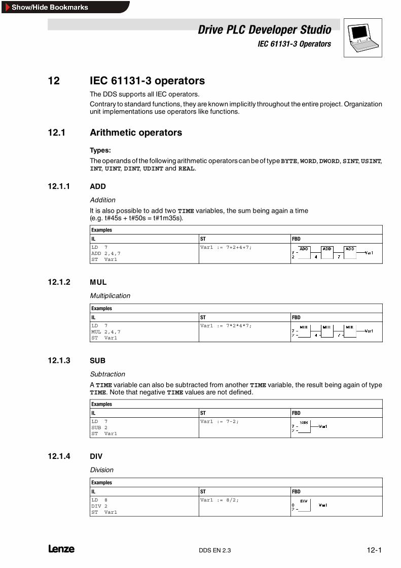
Drive PLC Developer StudioIEC 61131-3 Operators
12-1l DDS EN 2.3
12 IEC 61131-3 operatorsThe DDS supports all IEC operators.
Contrary to standard functions, they are known implicitly throughout the entire project. Organizationunit implementations use operators like functions.
12.1 Arithmetic operators
Types:
Theoperands of the following arithmetic operators can beof typeBYTE,WORD,DWORD,SINT,USINT,INT, UINT, DINT, UDINT and REAL.
12.1.1 ADD
Addition
It is also possible to add two TIME variables, the sum being again a time(e.g. t#45s + t#50s = t#1m35s).
Examples
IL ST FBD
LD 7ADD 2,4,7ST Var1
Var1 := 7+2+4+7;
12.1.2 MUL
Multiplication
Examples
IL ST FBD
LD 7MUL 2,4,7ST Var1
Var1 := 7*2*4*7;
12.1.3 SUB
Subtraction
A TIME variable can also be subtracted from another TIME variable, the result being again of typeTIME. Note that negative TIME values are not defined.
Examples
IL ST FBD
LD 7SUB 2ST Var1
Var1 := 7-2;
12.1.4 DIV
Division
Examples
IL ST FBD
LD 8DIV 2ST Var1
Var1 := 8/2;

Drive PLC Developer StudioIEC 61131-3 Operators
12-2 lDDS EN 2.3
Library CheckDiv.lib
The library CheckDiv contains the global variable g_bErrorCheckDiv
• Open the library management with Window�Library Manager.
• Insert the library from the library folder. Via the menu command Insert�Additional Library,you can select the library and insert it into the actual project.
• Select the library in the library management. On the index card Global Variables, thevariable and additional information are listed.
Note!The global variable g_bErrorCheckDiv checks for divisions by zero.
The library function CheckDiv recognizes that the target system has executed a division by zero.
• The global variable g_bErrorCheckDiv is set to TRUE.
• The status TRUE is not set back during runtime. If the status = TRUE, at least once a divisionby zero has been executed.
Note!Use of CheckDiv functions.
CheckDiv functions do not allow divisions by zero. The divisor zero is replaced by one.
The following functions are available in CheckDiv.lib.
CheckDivByte
CheckDivDint
CheckDivDWord
CheckDivInt
CheckDivReal
CheckDivSInt
CheckDivUDint
CheckDivUInt
CheckDivUSInt
CheckDivWord
If a DIV operator is used, the value of the divisor can be checked. The respective function must haveexactly the shown syntax. In the case of a division by zero(100/0), the divisor is replaced by one(100/1). At the same time the variable g_bErrorCheckdiv is set to TRUE.

Drive PLC Developer StudioIEC 61131-3 Operators
12-3l DDS EN 2.3
Implementing CheckDivReal
Declaration part
FUNCTION CheckDivReal:REALVAR_INPUTdivisor:REAL;
END_VAR
Instruction part
IF divisor = 0 THENCheckDivReal:=1;
ELSECheckDivReal:=divisor;
END_IF;
The operator DIV uses the result of function CheckDivReal as divisor. In the program exampleillustrated below, this prevents a division by 0 by setting the divisor (d) from 0 to 1. The result erg ofthe division is therefore 799.
12.1.5 MOD
Modulo division
Modulo divisionof avariable of typeBYTE;WORD;DWORD;SINT;USINT;INT;UINT;DINT;UDINTwithanother variable of one of these types. The result of this function is an integer remainder of thedivision.
Examples
IL ST FBD
LD 9MOD 2ST Var1 (* Var1 = 1 *)
Var1 := 9 MOD 2;
12.1.6 INDEXOF
The result of this function is the internal index of an organization unit.
Examples
IL ST FBD
Var1 :=INDEXOF(organizationunit2);

Drive PLC Developer StudioIEC 61131-3 Operators
12-4 lDDS EN 2.3
12.1.7 SIZEOF
The result of this function is the number of bytes required by the specified data type.
Examples
ILDeclaration
STDeclaration
FBD
arr1:ARRAY[0..4] OF INT;Var1:=INT;ImplementationLD arr1SIZEOFST Var1 (* Var1 = 10 *)
arr:ARRAY[0...4]OF INT;Var1:INT;ImplementationVar1=SIZE OF (arr1);
12.2 Bit-string operators
Types:
The operands of the following bit-string operators should be of type BOOL, BYTE, WORD or DWORD.
12.2.1 AND
Bit-by-bit AND of bit operands
Examples
IL Var1 : BYTE;LD 2#1001_0011AND 2#1000_1010ST Var1 (* Var1 = 2#1000_0010 *)
FBD
ST var1 := 2#1001_0011 AND 2#1000_1010
Note!Make sure to observe the following when using 68xxx or C-code generators in the FBD for theillustrated program sequence.
As soon as the input variable a assumes the value FALSE, the assignment of the value of the secondinput variable at the AND operator organization unit to the variable z will no longer be performed asa consequence of the optimized processing procedure within the FBD.
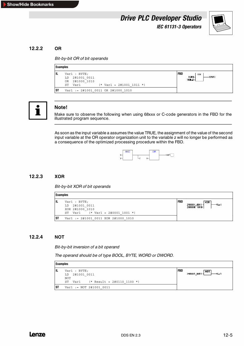
Drive PLC Developer StudioIEC 61131-3 Operators
12-5l DDS EN 2.3
12.2.2 OR
Bit-by-bit OR of bit operands
Examples
IL Var1 : BYTE;LD 2#1001_0011OR 2#1000_1010ST Var1 (* Var1 = 2#1001_1011 *)
FBD
ST Var1 := 2#1001_0011 OR 2#1000_1010
Note!Make sure to observe the following when using 68xxx or C-code generators in the FBD for theillustrated program sequence.
As soon as the input variable a assumes the value TRUE, the assignment of the value of the secondinput variable at the OR operator organization unit to the variable z will no longer be performed asa consequence of the optimized processing procedure within the FBD.
12.2.3 XOR
Bit-by-bit XOR of bit operands
Examples
IL Var1 : BYTE;LD 2#1001_0011XOR 2#1000_1010ST Var1 (* Var1 = 2#0001_1001 *)
FBD
ST Var1 := 2#1001_0011 XOR 2#1000_1010
12.2.4 NOT
Bit-by-bit inversion of a bit operand
The operand should be of type BOOL, BYTE, WORD or DWORD.
Examples
IL Var1 : BYTE;LD 2#1001_0011NOTST Var1 (* Result = 2#0110_1100 *)
FBD
ST Var1 := NOT 2#1001_0011

Drive PLC Developer StudioIEC 61131-3 Operators
12-6 lDDS EN 2.3
12.3 Bit-shift operators
Types:
The operands of the following bit shift operators should be of type BYTE, WORD or DWORD.
12.3.1 SHL
Shifting the bits of an operand to the left
Example IL:LD 1SHL 1ST Var1 (* Var1 = 2 *)
A:= SHL (IN, N)ST Var1 (* Var1 = 2 *)
IN is shifted to the left by N bits, and padded with zeros from the right.
12.3.2 SHR
Shifting the bits of an operand to the right
Example IL:LD 32SHL 2ST Var1 (* Var1 = 8 *)
A:= SHR (IN, N)ST Var1 (* Var1 = 8 *)
IN is shifted to the right by N bits, and padded with zeros from the left.
12.3.3 ROL
Rotating the bits of an operand to the left
Example IL:LD 2#1001_0011ROL 3ST Var1
A:= ROL (IN, N)ST Var1(* Var1 = 2#1001_1100 *
IN is rotated by one bit position to the left N times, with the bit on the extreme left being reinsertedfrom the right.
Tip!The number of bits for the arithmetic operation is specified by the data type of input variable IN. Aconstant is considered as the lowest-order data type. The data type of the output variable has noeffect on the arithmetic operation.

Drive PLC Developer StudioIEC 61131-3 Operators
12-7l DDS EN 2.3
12.3.4 ROR
Rotating the bits of an operand to the right
Example IL:LD 2#1001_0011ROR 3ST Var1
A:= ROR (IN, N)ST Var1(* Var1 = #0111_0010 *)
IN is rotated by one bit position to the right N times, with the bit being on the extreme right beingreinserted from the left.
Tip!The number of bits for the arithmetic operation is specified by the data type of input variable IN. Aconstant is considered as the lowest-order data type. The data type of the output variable has noeffect on the arithmetic operation.

Drive PLC Developer StudioIEC 61131-3 Operators
12-8 lDDS EN 2.3
12.4 Selection operators
All selection operations can also be carried out on variables.
For better understanding, the examples below use constants as operands.
12.4.1 SEL
Binary selection
OUT := SEL(G, IN0, IN1)
means:
IF G THENOUT:=IN1;
ELSEOUT:=IN0;
END_IF
IN0, IN1 and OUT can be of any type, G must be of type BOOL.
The result of the selection is
• IN0 if G is FALSE,
• IN1 if G is TRUE.
Examples
IL ST FBD
LD TRUESEL 3,4 (*IN0=3, IN1=4*)ST Var1 (*Result=4 *)
LD FALSESEL 3,4ST Var1 (*Result=3*)
Var1:=SEL(TRUE,3,4);(*Result Var1=4*)
Tip!Processing is as follows for runtime optimization.
An expression attached to the input side of IN0 will be computed only if G = FALSE.
An expression attached to the input side of IN1 will be computed only if G = TRUE.
Simulation will compute all branches.
12.4.2 MAX
Maximum function
Returns the greater of two values.
OUT := MAX(IN0, IN1)
IN0, IN1 and OUT can be of any type.
Examples
IL ST FBD
LD 90MAX 30MAX 40MAX 77ST Var1 (* Var1 = 90 *)
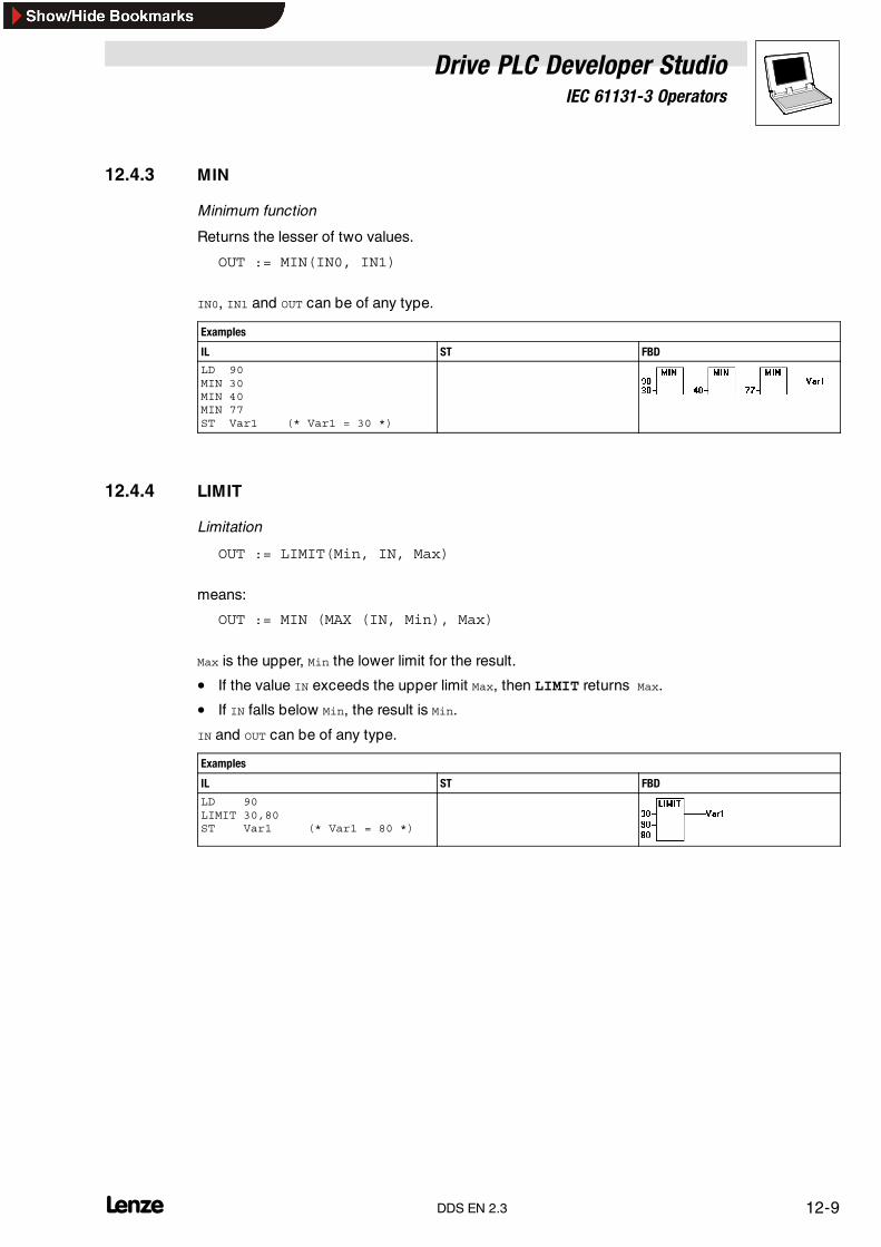
Drive PLC Developer StudioIEC 61131-3 Operators
12-9l DDS EN 2.3
12.4.3 MIN
Minimum function
Returns the lesser of two values.
OUT := MIN(IN0, IN1)
IN0, IN1 and OUT can be of any type.
Examples
IL ST FBD
LD 90MIN 30MIN 40MIN 77ST Var1 (* Var1 = 30 *)
12.4.4 LIMIT
Limitation
OUT := LIMIT(Min, IN, Max)
means:
OUT := MIN (MAX (IN, Min), Max)
Max is the upper, Min the lower limit for the result.
• If the value IN exceeds the upper limit Max, then LIMIT returns Max.
• If IN falls below Min, the result is Min.
IN and OUT can be of any type.
Examples
IL ST FBD
LD 90LIMIT 30,80ST Var1 (* Var1 = 80 *)
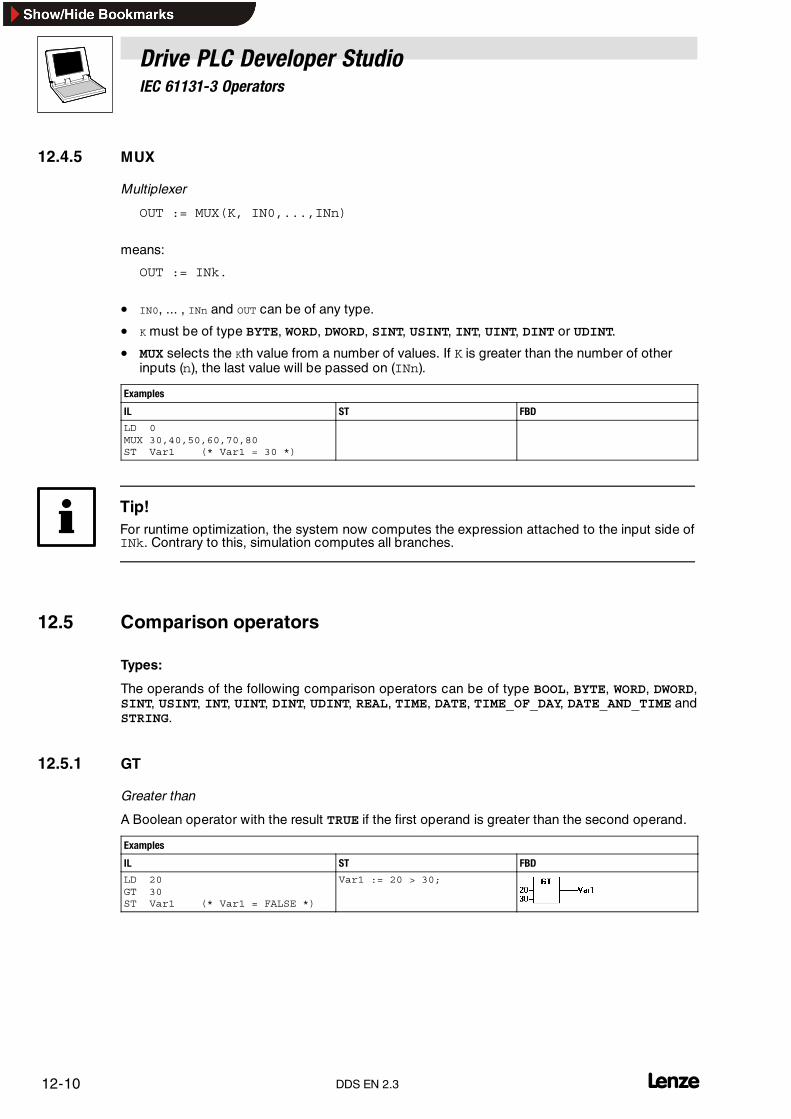
Drive PLC Developer StudioIEC 61131-3 Operators
12-10 lDDS EN 2.3
12.4.5 MUX
Multiplexer
OUT := MUX(K, IN0,...,INn)
means:
OUT := INk.
• IN0, ... , INn and OUT can be of any type.
• K must be of type BYTE, WORD, DWORD, SINT, USINT, INT, UINT, DINT or UDINT.
• MUX selects the Kth value from a number of values. If K is greater than the number of otherinputs (n), the last value will be passed on (INn).
Examples
IL ST FBD
LD 0MUX 30,40,50,60,70,80ST Var1 (* Var1 = 30 *)
Tip!For runtime optimization, the system now computes the expression attached to the input side ofINk. Contrary to this, simulation computes all branches.
12.5 Comparison operators
Types:
The operands of the following comparison operators can be of type BOOL, BYTE, WORD, DWORD,SINT, USINT, INT, UINT, DINT, UDINT, REAL, TIME, DATE, TIME_OF_DAY, DATE_AND_TIME andSTRING.
12.5.1 GT
Greater than
A Boolean operator with the result TRUE if the first operand is greater than the second operand.
Examples
IL ST FBD
LD 20GT 30ST Var1 (* Var1 = FALSE *)
Var1 := 20 > 30;
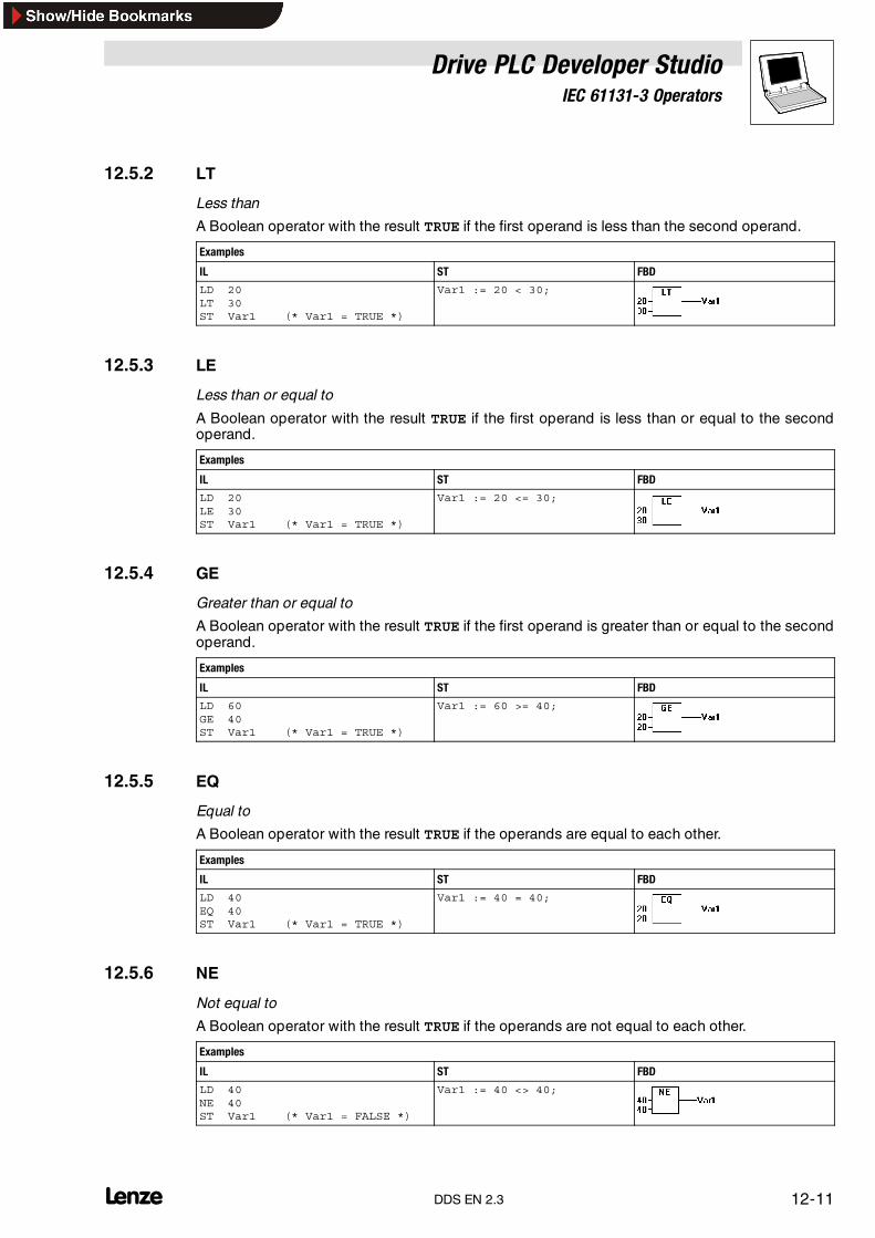
Drive PLC Developer StudioIEC 61131-3 Operators
12-11l DDS EN 2.3
12.5.2 LT
Less than
A Boolean operator with the result TRUE if the first operand is less than the second operand.
Examples
IL ST FBD
LD 20LT 30ST Var1 (* Var1 = TRUE *)
Var1 := 20 < 30;
12.5.3 LE
Less than or equal to
A Boolean operator with the result TRUE if the first operand is less than or equal to the secondoperand.
Examples
IL ST FBD
LD 20LE 30ST Var1 (* Var1 = TRUE *)
Var1 := 20 <= 30;
12.5.4 GE
Greater than or equal to
A Boolean operator with the result TRUE if the first operand is greater than or equal to the secondoperand.
Examples
IL ST FBD
LD 60GE 40ST Var1 (* Var1 = TRUE *)
Var1 := 60 >= 40;
12.5.5 EQ
Equal to
A Boolean operator with the result TRUE if the operands are equal to each other.
Examples
IL ST FBD
LD 40EQ 40ST Var1 (* Var1 = TRUE *)
Var1 := 40 = 40;
12.5.6 NE
Not equal to
A Boolean operator with the result TRUE if the operands are not equal to each other.
Examples
IL ST FBD
LD 40NE 40ST Var1 (* Var1 = FALSE *)
Var1 := 40 <> 40;
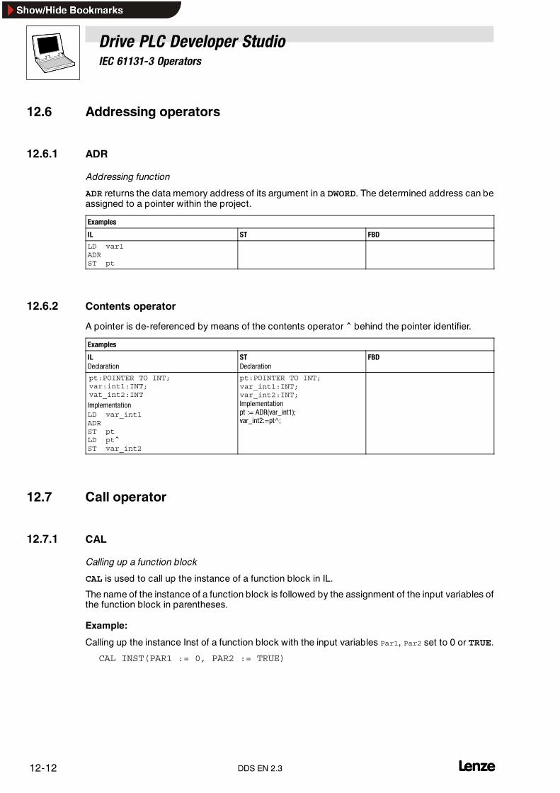
Drive PLC Developer StudioIEC 61131-3 Operators
12-12 lDDS EN 2.3
12.6 Addressing operators
12.6.1 ADR
Addressing function
ADR returns the data memory address of its argument in a DWORD. The determined address can beassigned to a pointer within the project.
Examples
IL ST FBD
LD var1ADRST pt
12.6.2 Contents operator
A pointer is de-referenced by means of the contents operator ^ behind the pointer identifier.
Examples
ILDeclaration
STDeclaration
FBD
pt:POINTER TO INT;var:int1:INT;vat_int2:INT
ImplementationLD var_int1ADRST ptLD pt^ST var_int2
pt:POINTER TO INT;var_int1:INT;var_int2:INT;Implementationpt := ADR(var_int1);var_int2:=pt^;
12.7 Call operator
12.7.1 CAL
Calling up a function block
CAL is used to call up the instance of a function block in IL.
The name of the instance of a function block is followed by the assignment of the input variables ofthe function block in parentheses.
Example:
Calling up the instance Inst of a function block with the input variables Par1, Par2 set to 0 or TRUE.
CAL INST(PAR1 := 0, PAR2 := TRUE)

Drive PLC Developer StudioIEC 61131-3 Operators
12-13l DDS EN 2.3
12.8 Assignment operator
12.8.1 MOVE
Assignment operator
The MOVE command is useful only in the LD editor.
If EN is TRUE, the content of variable a is transferred to variable b.
Examples
IL ST LD

Drive PLC Developer StudioIEC 61131-3 Operators
12-14 LDDS EN 2.3

Drive PLC Developer StudioIEC 61131-3 Operands
13-1l DDS EN 2.3
13 IEC 61131-3 operandsIn the DDS, operands can be constants, variables, addresses and function calls.
13.1 Constants
Note!Not all automation systems support the various different data types.
13.1.1 Number constants
Numerical values can be binary numbers, octal numbers, decimal numbers and hexadecimalnumbers.
• If an integer is not a decimal number, its base followed by a hash # must be written in front ofthe integer constant.
• In the case of hexadecimal numbers, the numerical values for numbers 10 to 15 are specifiedwith the letters A-F as is common practice.
• Underscores are not allowed in numerical values with the exception of binary numbers.
Examples:
14 (* Decimal number *)2#1001_0011 (* Binary number *)8#67 (* Octal number *)16#A (* Hexadecimal number *)
• The type of these numerical values can be: BYTE, WORD, DWORD, SINT, USINT, INT, UINT,DINT, UDINT, REAL or LREAL.
• Implicit conversions from ”higher-” to ” lower-order” types are not allowed.A DINT variable cannot that easily be used as INT variable.In such cases, use the type conversion functions of the standard library.
13.1.2 BOOL constants
BOOL constants are TRUE and FALSE. They take up 1 Byte memory.
13.1.3 TIME constants
The DDS allows the declaration of TIME constants.
These are specifically used for the timers of the standard library. A TIME constant always consistsof a leading t or T (or time or TIME in full text) and a hash #.
This is followed by the actual time declaration that may consist of days (d), hours (h), minutes (m),seconds (s) and milliseconds (ms).
Note that time specifications must be sorted by size (d before h before m before s before ms), whilenot all specifications must occur.
Examples of correct TIME constants in an ST assignment:
TIME1 := T#14ms;TIME1 := T#100s12ms (*Overflow in the highest-order componentallowed*)TIME1 := t#12h34m15s;
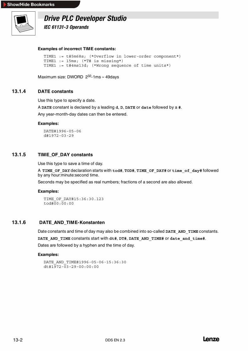
Drive PLC Developer StudioIEC 61131-3 Operands
13-2 lDDS EN 2.3
Examples of incorrect TIME constants:
TIME1 := t#5m68s; (*Overflow in lower-order component*)TIME1 := 15ms; (*T# is missing*)TIME1 := t#4ms13d; (*Wrong sequence of time units*)
Maximum size: DWORD 232-1ms ≈ 49days
13.1.4 DATE constants
Use this type to specify a date.
A DATE constant is declared by a leading d, D, DATE or date followed by a #.
Any year-month-day dates can then be entered.
Examples:
DATE#1996-05-06d#1972-03-29
13.1.5 TIME_OF_DAY constants
Use this type to save a time of day.
A TIME_OF_DAY declaration starts with tod#, TOD#, TIME_OF_DAY# or time_of_day# followedby any hour:minute:second time.
Seconds may be specified as real numbers; fractions of a second are also allowed.
Examples:
TIME_OF_DAY#15:36:30.123tod#00:00:00
13.1.6 DATE_AND_TIME-Konstanten
Date constants and time of day may also be combined into so-called DATE_AND_TIME constants.
DATE_AND_TIME constants start with dt#, DT#, DATE_AND_TIME# or date_and_time#.
Dates are followed by a hyphen and the time of day.
Examples:
DATE_AND_TIME#1996-05-06-15:36:30dt#1972-03-29-00:00:00

Drive PLC Developer StudioIEC 61131-3 Operands
13-3l DDS EN 2.3
13.1.7 REAL and LREAL constants
REAL constants may be decimal fractions and exponents
using the American way of decimal points.
Examples:
7.4 (* instead of 7,4 *)1.64e+009 (* instead of 1,64e+009 *)
13.1.8 STRING constants
A string can be any character sequence.
STRING constants start and end with single quotes. Umlauts and white spaces are also allowed andprocessed like any other character.
In character sequences, the combination of the dollar sign $ followed by two hexadecimal numberswill be interpreted as hexadecimal representation of the 8 bit character code.
Occurrences in a character sequence of combinations of two characters starting with the dollar signwill be interpreted as follows:
$$ Dollar sign$’ Single quote$L or $l Line feed$N or $n New line$P or $p Page feed$R or $r Line break$T or $t Tabulator
Examples:
’Hello’’Susi and Claus’’:-)’
13.1.9 Type constants (Typed Literals)
As a rule, IEC constants use the lowest possible data type. If a different data type is to be applied,use Typed Literals without the need of having to explicitly declare the constant.
The constant is given a type-defining prefix.Notation <Type>#<Literal>
• <Type> specifies the required data type. The type must be written in uppercase.
BOOL, SINT, USINT, BYTE, INT, UINT, WORD, DINT, UDINT, DWORD, REAL,LREAL
• <Literal> specifies the constant. The input must be compatible with the data type specifiedunder <type>.
var1:=DINT#34;
An error message appears if the constant cannot be transferred into the target type without dataloss. Typed literals can be used where normal constants are applied.

Drive PLC Developer StudioIEC 61131-3 Operands
13-4 lDDS EN 2.3
13.2 Variables
Variables are declared either locally in the declaration part of an organization unit or in the globalvariable lists.
• Variables can be used wherever where the declared type allows it.
• The available variables can be called via the Help Manager.
13.2.1 System variable
System variables are implicitly declared variables that depend on the selected automation systemand were added to the automation system’s PLC configuration.
To find out the automation system’s system variable, select the commandInsert����Operand. In the dialog box Help Manager then select category System variable.
13.2.2 Access to variables of arrays, structures and organization units
Two-dimensional array components are accessed with the following syntax:
<Feldname>[Index1, Index2]
Variables of structures are accessed with the following syntax:
<Structure name>.<Variable name>
Variables of function blocks and programs are accessed with the following syntax:
<Organization unit name>.<Variable name>
13.2.3 Addressing bits in variables
Integer variables allow individual bits to be addressed. For this purpose, the variable is given anindex of the bit to be addressed. The bit index may be given through any constant. Indexing is0-based.
a : INT;b : BOOL;...a.2 := b;
The third bit of variable a is set to the value of variable b. The following error message is output if theindex is greater than the variable’s bit width:Index ’<n>’ outside the range valid for variable ’<var>’!
The following variable types allow bit addressing.
SINT, INT, DINT, USINT, UINT, UDINT, BYTE, WORD, DWORD
The following error message is output if the variable type is not permitted.Bit access must not be assigned to a VAR_IN_OUT variable!
13.2.4 Identifiers
An identifier is a sequence of letters, numbers and underscores starting with a letter or anunderscore.
Variable identifiers must not:
• contain white spaces and umlauts,
• be declared twice,
• be identical to keywords.

Drive PLC Developer StudioIEC 61131-3 Operands
13-5l DDS EN 2.3
Furthermore:
• Case sensitivity is not an option for variables.(Example: VAR1, Var1 and var1 are not different variables)
• Underscores in an identifier are significant.(Example: A_BCD and AB_CD are interpreted as different identifiers.)
• Multiple successive underscores at the beginning of or within an identifier are not allowed.
• The first 32 characters are significant.
13.3 Addresses
13.3.1 Address
For a declaration, variables can be assigned to a physical memory location (PLC address)by meansof the keyword AT.
The address specification structure is established with the help of special character lines.
The character sequence starts with a ”%” followed by a range prefix and a prefix (data type) for thesize. It ends with a sequence of numbers that specify the direct memory location.
The following range prefixes are supported:
I InputQ OutputM Flag (internal memory)
The following size prefixes are supported:
X Single bitNone OptionalB Byte (8 bits)W Word (16 bits)D Double word (32 bits)
Inputs/outputs:
%IX0.0.0Character for physical address
Range prefixData type
Module numberWord address
Bit address
Module number
The module number specifies the automation system module (system organization unit) to beapproached.
Examples:
%QX0.0.2 Output bit 2%IW0.0.1 Input bit 1%MB7 Flag byte 7%MW1 Flag word 1%MD3 Flag double word 3%MX1.2 Third flag bit in flag word 1

Drive PLC Developer StudioIEC 61131-3 Operands
13-6 lDDS EN 2.3
Memory/Address ManagerThe memory is divided into words, with a word being made up of 16 bits (bit0 to bit15).The table below illustrates the memory data structure:
Note!Boolean values are assigned byte-by-byte unless a single bit address is explicitly specified. A valuechange of varbool1 AT%MW0 affects the range from %MX0.0 to %MX0.7
13.3.2 Flags
Tip!The flag range size is dependent on the selected automation system.
Example1:
%MD48
%MD48
%MW96%MW97
%MB192%MB193%MB194%MB195
addresses bytes nos. 192, 193, 194 and 195 (48 * 4 = 192) in the flag range.The first byte is byte no. 0.
Example2:
%MX5.0
addresses the first bit in the fifth word in the flag range.(Bits are generally saved word by word.)

Drive PLC Developer StudioIEC 61131-3 Operands
13-7l DDS EN 2.3
13.4 Function calls
In ST, a function call can also be an operand.
Example:
Result := Fct(7) + 3;

Drive PLC Developer StudioIEC 61131-3 Operands
13-8 LDDS EN 2.3

Drive PLC Developer StudioIEC 61131-3 Standard functions
14-1l DDS EN 2.3
14 IEC 61131-3 standard functionsType conversion functions
Conversions between integer number types.
BOOL_TO BOOL � type X
TO_BOOL Type X � BOOL
TIME_TO / TIME_OF_DAY TIME / TIME_OF_DAY � type X
DATE_TO / DT_TO DATE / DATE_AND_TIME � type X
STRING_TO STRING � type X
TRUNC REAL � INT
Numerical functions
ABS Absolute value
SQRT Square root
LN Natural logarithm
LOG Logarithm to the base of 10
EXP Exponential function
SIN Sine calculation in radians
COS Cosine calculation in radians
TAN Tangent calculation in radians
ASIN Arc sine calculation in radians
ACOS Arc cosine calculation in radians
ATAN Arc tangent calculation in radians
EXPT Exponentiation of one variable to another
STRING functions
LEN Returns the length of a string
LEFT Returns a left start string of a string
RIGHT Returns a right start string of a string
MID Returns a segment of a string
CONCAT Concatenates two strings
INSERT Inserts a string into another string from a specific position
DELETE Deletes a segment from a string from a specific position
REPLACE Replaces a segment within a string with another string
FIND Looks for a segment within a string
Bistable function blocks
SR Bistable function block (dominant set)
RS Bistable function block (dominant reset)
SEMA Software semaphore (interruptible)
Edge detection
R_TRIG Rising edge detector
F_TRIG Falling edge detector
Counters
CTU Up counter
CTD Down counter
CTUD Up and down counter
Timers
TP Pulse encoder
TON Timer on-delay
TOF Timer off-delay
RTC* Runtime clock*
* Not supported
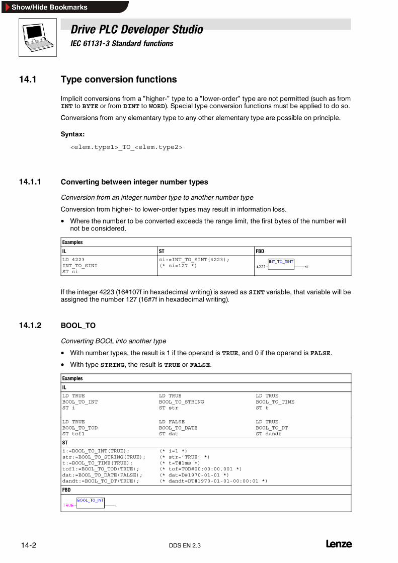
Drive PLC Developer StudioIEC 61131-3 Standard functions
14-2 lDDS EN 2.3
14.1 Type conversion functions
Implicit conversions from a ”higher-” type to a ” lower-order” type are not permitted (such as fromINT to BYTE or from DINT to WORD). Special type conversion functions must be applied to do so.
Conversions from any elementary type to any other elementary type are possible on principle.
Syntax:
<elem.type1>_TO_<elem.type2>
14.1.1 Converting between integer number types
Conversion from an integer number type to another number type
Conversion from higher- to lower-order types may result in information loss.
• Where the number to be converted exceeds the range limit, the first bytes of the number willnot be considered.
Examples
IL ST FBD
LD 4223INT_TO_SINIST si
si:=INT_TO_SINT(4223);(* si=127 *)
If the integer 4223 (16#107f in hexadecimal writing) is saved as SINT variable, that variable will beassigned the number 127 (16#7f in hexadecimal writing).
14.1.2 BOOL_TO
Converting BOOL into another type
• With number types, the result is 1 if the operand is TRUE, and 0 if the operand is FALSE.
• With type STRING, the result is TRUE or FALSE.
Examples
IL
LD TRUEBOOL_TO_INTST i
LD TRUEBOOL_TO_STRINGST str
LD TRUEBOOL_TO_TIMEST t
LD TRUEBOOL_TO_TODST tof1
LD FALSEBOOL_TO_DATEST dat
LD TRUEBOOL_TO_DTST dandt
ST
i:=BOOL_TO_INT(TRUE);str:=BOOL_TO_STRING(TRUE);t:=BOOL_TO_TIME(TRUE);tof1:=BOOL_TO_TOD(TRUE);dat:=BOOL_TO_DATE(FALSE);dandt:=BOOL_TO_DT(TRUE);
(* i=1 *)(* str=’TRUE’ *)(* t=T#1ms *)(* tof=TOD#00:00:00.001 *)(* dat=D#1970-01-01 *)(* dandt=DT#1970-01-01-00:00:01 *)
FBD

Drive PLC Developer StudioIEC 61131-3 Standard functions
14-3l DDS EN 2.3
14.1.3 TO_BOOL
Converting from any type to BOOL
• The result is TRUE if the operand is not 0 and FALSE if the operand is 0.
• With type STRING the result is TRUE if the operand is TRUE, otherwise the result is FALSE.
Examples
IL
LD 213BYTE_TO_BOOLST b (* b=TRUE *)
LD 0INT_TO_BOOLST b (* b=FALSE *)
LD T#5msTIME_TO_BOOLST b (* b=TRUE *)
LD ’TRUE’STRING_TO_BOOLST b (* b=TRUE *)
ST
b:=BYTE_TO_BOOL(2#11010101);b:=INT_TO_BOOL(0);b:=TIME_TO_BOOL(T#5ms);b:=STRING_TO_BOOL(’TRUE’);
(* b=TRUE *)(* b=FALSE *)(* b=TRUE *)(* b=TRUE *)
FBD
14.1.4 TIME_TO / TIME_OF_DAY
Converting from TIME or TIME_OF_DAY to another type
Internally, the time is saved as aDWORD inmilliseconds (withTIME_OF_DAY from 00:00 o’clock). Thisvalue is converted.
• With type STRING, the result is the time constant.
• Conversion from higher- to lower-order types may result in information loss.
Examples
IL
LD T#12msTIME_TO_STRINGST str
LD T#300000msTIME_TO_DWORDST dw
LD TOD#00:00:00.012TOD_TO_SINTST si
ST
str:=TIME_TO_STRING(T#12ms);dw:=TIME_TO_DWORD(T#5m);si:=TOD_TO_SINT(TOD#00:00:00.012);
(* str=’T#12ms’ *)(* dw=300000 *)(* si=12 *)
FBD

Drive PLC Developer StudioIEC 61131-3 Standard functions
14-4 lDDS EN 2.3
14.1.5 DATE_TO / DT_TO
Converting from type DATE or DATE_AND_TIME to another type
Internally, the date is saved in a DWORD in seconds since the 1st of January 1970. This value isconverted.
• With type STRING, the result is a date constant.
• Conversion from higher- to lower-order types may result in information loss.
Examples
IL
LD D#1970-01-01DATE_TO_BOOLST b
LD D#1970-01-15DATE_TO_INTST i
LD DT#1970-01-15-05:05:05DT_TO_BYTEST byt
LD DT#1998-02-13-14:20DT_TO_STRINGST str
ST
b:=DATE_TO_BOOL(D#1970-01-01);i:=DATE_TO_INT(D#1970-01-15);byt:=DT_TO_BYTE(DT#1970-01-15-05:05:05);str:=DT_TO_STRING(DT#1998-02-13-14:20);
(* b=FALSE *)(* i=29952 *)(* byt=129 *)(* str=’DT#1998-02-13-14:20’ *)
FBD
14.1.6 STRING_TO
Converting STRING into another type
The operand of type STRING must have a valid target type value as otherwisethe result will be 0.
Examples
IL
LD ’TRUE’STRING_TO_BOOLST b
LD ’123’STRING_TO_WORDST w
LD ’t#127ms’STRING_TO_TIMEST t
ST
b:=STRING_TO_BOOL(’TRUE’);w:=STRING_TO_WORD(’123’);t:=STRING_TO_TIME(’T#127ms’);
(* b=TRUE *)(* w=123 *)(* t=T#127ms *)
14.1.7 TRUNC
Converting from REAL to type INT
• Conversion uses the integer component of the floating-point number.
• Conversion from higher- to lower-order types may result in information loss.
Examples
IL ST
LD 1.9TRUNCST i (* i=1 *)
LD -1.4TRUNCST i (* i=-1 *)
i:=TRUNC(1.9);i:=TRUNC(-1.4);

Drive PLC Developer StudioIEC 61131-3 Standard functions
14-5l DDS EN 2.3
14.2 Numerical functions
14.2.1 ABS
Returns the absolute value of a number
Examples
IL ST FBD
LD -2ABSST i (* i=2 *)
i:=ABS(-2);
14.2.2 SQRT
Returns the square root of a number
Examples
IL ST FBD
LD 16SQRTST q (* q=4 *)
q:=SQRT(16);
14.2.3 LN
Returns the natural logarithm of a number
Examples
IL ST FBD
LD 45LNST q (* q=3.806663 *)
q:=LN(45);
14.2.4 LOG
Returns the logarithm to the base of 10 of a number
Examples
IL ST FBD
LD 314.5LOGST q (* q=2.497621 *)
q:=LOG(314.5);
14.2.5 EXP
Returns the exponential function
Examples
IL ST FBD
LD 23EXPST q (* q=9.744791e+009 *)
q:=EXP(23);

Drive PLC Developer StudioIEC 61131-3 Standard functions
14-6 lDDS EN 2.3
14.2.6 SIN
Returns the sine of a number in radians
Examples
IL ST FBD
LD 0.5SINST q (* q=0.4794255 *)
q:=SIN(0.5);
14.2.7 COS
Returns the cosine of a number in radians
Examples
IL ST FBD
LD 0.5COSST q (* q=0.8775826 *)
q:=COS(0.5);
14.2.8 TAN
Returns the tangent of a number in radians
Examples
IL ST FBD
LD 0.5TANST q (* q=0.5463024 *)
q:=TAN(0.5);
14.2.9 ASIN
Returns the arc sine (inversion of sine) of a number in radians
Examples
IL ST FBD
LD 0.5ASINST q (* q=0.5235988 *)
q:=ASIN(0.5);
14.2.10 ACOS
Returns the arc cosine (inversion of cosine) of a number in radians
Examples
IL ST FBD
LD 0.5ACOSST q (* q=1.047198 *)
q:=ACOS(0.5);

Drive PLC Developer StudioIEC 61131-3 Standard functions
14-7l DDS EN 2.3
14.2.11 ATAN
Returns the arc tangent (inversion of tangent) of a number in radians
Examples
IL ST FBD
LD 0.5ATANST q (* q=0.4636476 *)
q:=ATAN(0.5);
14.2.12 EXPT
Exponentiation of one variable with another:
OUT = IN1IN2
• OUT is of type REAL.
• IN1 and IN2 can be of type BYTE, WORD, DWORD, INT, DINT, REAL.
Examples
IL ST FBD
LD 7EXPT 2ST var1 (* var1=49 *)
var1:=EXPT(7,2);
14.3 STRING functions
Note!The permissible string length is dependent on the applied automation system.If the length is exceeded, an error message will be displayed in online mode.
14.3.1 LEN
Returns the length of a string• STR is of type STRING, the return value of the function type INT.
Examples
IL ST FBD
LD ’SUSI’LENST Var1 (* Var1=4 *)
Var1:=LEN(’SUSI’);
14.3.2 LEFT
Returns a left start string of a string• STR is of type STRING, SIZE of type INT, the return value of the function type STRING.
• LEFT(STR,SIZE) means: Take the first SIZE characters from the left in the string STR.
Examples
IL ST FBD
LD ’SUSI’LEFT 3ST Var1 (* Var1=’SUS’ *)
Var1:=LEFT(’SUSI’,3);

Drive PLC Developer StudioIEC 61131-3 Standard functions
14-8 lDDS EN 2.3
14.3.3 RIGHT
Returns a right start string of a string
• STR is of type STRING, SIZE of type INT, the return value of the function type STRING.
• RIGHT (STR, SIZE) means: Take the first SIZE characters from the right in the string STR.
Examples
IL ST FBD
LD ’SUSI’RIGHT 3ST Var1 (* Var1=’USI’ *)
Var1:=RIGHT(’SUSI’,3);
14.3.4 MID
Returns a segment of a string
• STR is of type STRING, LEN and POS of type INT, the return value of the function typeSTRING.
• MID (STR, LEN, POS) means: Get LEN characters from the string STR starting with thecharacter at POS.
Examples
IL ST FBD
LD ’SUSI’MID 2,2ST Var1 (* Var1=’US’ *)
Var1:=MID(’SUSI’,2,2);
14.3.5 CONCAT
Concatenation
Concatenating two strings
• STR1, STR2 and the return value of the function are of type STRING.
Examples
IL ST FBD
LD ’SUSI’CONCAT ’WILLI’ST Var1(* Var1=’SUSIWILLI’ *)
Var1:=CONCAT(’SUSI’,’WILLI’);
14.3.6 INSERT
Inserts a string into another string from a specific position
• STR1 and STR2 are of type STRING, POS of type INT, the return value of the function typeSTRING.
• INSERT(STR1, STR2, POS) means: Insert STR2 into STR1 after the POS-th position.
Examples
IL ST FBD
LD ’SUSI’INSERT ’XY’,2ST Var1(* Var1=’SUXYSI’ *)
Var1 := INSERT(’SUSI’,’XY’,2);

Drive PLC Developer StudioIEC 61131-3 Standard functions
14-9l DDS EN 2.3
14.3.7 DELETE
Deletes a segment from a string from a specific position
• STR1 is of type STRING, LEN and POS of type INT, the return value of the function typeSTRING.
• DELETE(STR, L, P) means: Delete L characters from STR, starting with the P th.
Examples
IL ST FBD
LD ’SUXYSI’DELETE 2,2ST Var1(* Var1=’SUSI’ *)
Var1:=DELETE(’SUXYSI’,2,2);
14.3.8 REPLACE
Replaces a segment within a string with another string
• STR1 and STR2 are of type STRING, LEN and POS of type INT, the return value of thefunction type STRING.
• REPLACE(STR1, STR2, L, P) means: Replace L characters from STR1 with STR2starting with the P-th character.
Examples
IL ST FBD
LD ’SUXYSI’REPLACE ’K’,2,2ST Var1(* Var1=’SKYSI’ *)
Var1:=REPLACE(’SUXYSI’,’K’,2,2);
14.3.9 FIND
Looks for a segment within a string
• STR1 and STR2 are of type STRING, the return value of the function type INT.
• FIND (STR1, STR2) means: Find the position of the first character of the first occurrenceof STR2 in STR1.
• If STR2 does not occur in STR1 , the return value will be :=0.
Examples
IL ST FBD
LD ’SUXYSI’FIND ’XY’ST Var1 (* Var1=3 *)
Var1:=FIND(’SUXYSI’,’XY’);
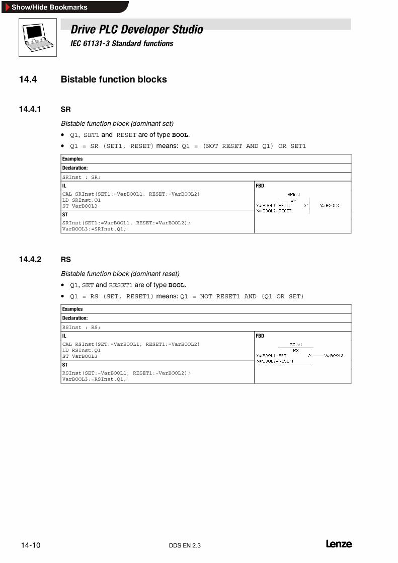
Drive PLC Developer StudioIEC 61131-3 Standard functions
14-10 lDDS EN 2.3
14.4 Bistable function blocks
14.4.1 SR
Bistable function block (dominant set)
• Q1, SET1 and RESET are of type BOOL.
• Q1 = SR (SET1, RESET) means: Q1 = (NOT RESET AND Q1) OR SET1
Examples
Declaration:
SRInst : SR;
IL FBD
CAL SRInst(SET1:=VarBOOL1, RESET:=VarBOOL2)LD SRInst.Q1ST VarBOOL3
ST
SRInst(SET1:=VarBOOL1, RESET:=VarBOOL2);VarBOOL3:=SRInst.Q1;
14.4.2 RS
Bistable function block (dominant reset)
• Q1, SET and RESET1 are of type BOOL.
• Q1 = RS (SET, RESET1) means: Q1 = NOT RESET1 AND (Q1 OR SET)
Examples
Declaration:
RSInst : RS;
IL FBD
CAL RSInst(SET:=VarBOOL1, RESET1:=VarBOOL2)LD RSInst.Q1ST VarBOOL3
ST
RSInst(SET:=VarBOOL1, RESET1:=VarBOOL2);VarBOOL3:=RSInst.Q1;

Drive PLC Developer StudioIEC 61131-3 Standard functions
14-11l DDS EN 2.3
14.4.3 SEMA
Software semaphore (interruptible)
X is an internal BOOL variable initialized with FALSE .
BUSY, CLAIM and RELEASE are of type BOOL.
• If SEMA is called and BUSY is TRUE, SEMA has already been assigned(SEMA was called using CLAIM = TRUE).
• If BUSY is FALSE, SEMA has either not been called yet or been enabled(call with RELEASE = TRUE).
BUSY = SEMA(CLAIM, RELEASE) means:
BUSY:=X;IF CLAIM THEN X:=TRUE;ELSIF RELEASE THEN BUSY:=FALSE; X:=FALSE;END_IF
Examples
Declaration:
SEMAInst : SEMA;
IL FBD
CAL SEMAInst(CLAIM:=VarBOOL1, RELEASE:=VarBOOL2)LD SEMAInst.BUSYST VarBOOL3
ST
SEMAInst(CLAIM:=VarBOOL1, RELEASE:=VarBOOL2);VarBOOL3:=SEMAInst.BUSY;

Drive PLC Developer StudioIEC 61131-3 Standard functions
14-12 lDDS EN 2.3
14.5 Edge detection
14.5.1 R_TRIG
Rising edge detector
FUNCTION_BLOCK R_TRIGVAR_INPUTCLK : BOOL;END_VARVAR_OUTPUTQ : BOOL;END_VARVARM : BOOL := FALSE;END_VARQ := CLK AND NOT M;M := CLK1;END_FUNCTION_BLOCK
As long as the input variable CLK is FALSE,the output Q and the auxiliary variable M will be FALSE .
As soon as CLK returns TRUE,Q will first return TRUE and then M will be switched to TRUE .
I.e.: with every subsequent function call, Qwill returnFALSE untilCLK has a falling and another risingedge.
Examples
Declaration:
RTRIGInst : R_TRIG;
IL FBD
CAL RTRIGInst(CLK:=VarBOOL1)LD RTRIGInst.QST VarBOOL2
ST
RTRIGInst(CLK:=VarBOOL1);VarBOOL2:=RTRIGInst.Q;

Drive PLC Developer StudioIEC 61131-3 Standard functions
14-13l DDS EN 2.3
14.5.2 F_TRIG
Falling edge detector
FUNCTION_BLOCK F_TRIGVAR_INPUTCLK : BOOL;END_VARVAR_OUTPUTQ : BOOL;END_VARVARM : BOOL := TRUE;END_VARQ := NOT CLK AND NOT M;M := NOT CLK;END_FUNCTION_BLOCK
As long as the input variable CLK returns TRUE,the output Q and the auxiliary variable M will be FALSE.
As soon as S1 is FALSE, Q will first return TRUE and then M will be switched to TRUE.
I.e.: with every subsequent function call,Q will return FALSE until CLK has a rising and another falling edge.
Examples
Declaration:
FTRIGInst : F_TRIG;
IL FBD
CAL FTRIGInst(CLK:=VarBOOL1)LD FTRIGInst.QST VarBOOL2
ST
FTRIGInst(CLK:=VarBOOL1);VarBOOL2:=FTRIGInst.Q;

Drive PLC Developer StudioIEC 61131-3 Standard functions
14-14 lDDS EN 2.3
14.6 Counters
14.6.1 CTU
Up counter
CU, RESET and Q are of type BOOL, PV and CV are of type INT.
• If RESET is TRUE, the counter variable CV is set to 0.
• Every positive edge at input CU increases CV by 1.As long as CV is less than PV max (i.e. no overflow).
• Q returns TRUE if CV is greater than or equal to the upper limit PV .
CTU(CU, RESET, PV, Q, CV) means:
• If RESET is TRUE, the counter variable CV will be initialized with 0.
• If CU has a rising edge, CV will be increased by 1.
Examples
Declaration:
CTUInst : CTU;
IL FBD
CAL CTUInst(CU:=VarBOOL1, RESET:=VarBOOL2, PV:=VarINT1)LD CTUInst.QST VarBOOL3LD CTUInst.CVST VarINT2
ST
CTUInst(CU:=VarBOOL1, RESET:=VarBOOL2, PV:=VarINT1);VarBOOL3:=CTUInst.Q;VarINT2:=CTUInst.CV;
14.6.2 CTD
Down counter
CD, LOAD and Q are of type BOOL, PV and CV are of type INT.
• If LOAD is TRUE, the counter variable CV will be set equal to the upper limit PV.
• If LOAD is FALSE, every function block call will decrease CV by 1.
• Q returns TRUE if CV is less than or equal to 0.
CTD(CD, LOAD, PV, Q, CV)
Examples
Declaration:
CTDInst : CTD;
IL FBD
CAL CTDInst(CD:=VarBOOL1, LOAD:=VarBOOL2, PV:=VarINT1)LD CTDInst.QST VarBOOL3LD CTDInst.CVST VarINT2
ST
CTUInst(CD:=VarBOOL1, LOAD:=VarBOOL2, PV:=VarINT1);VarBOOL3:=CTDInst.Q;VarINT2:=CTDInst.CV;

Drive PLC Developer StudioIEC 61131-3 Standard functions
14-15l DDS EN 2.3
14.6.3 CTUD
Up and down counter
CU, CD, RESET, LOAD, QU and QD are of type BOOL, PV and CV are of type INT.
• If RESET is valid, the counter variable CV will be initialized with 0.
• If LOAD is valid, CV will be initialized with PV .
• If positive edge CU is valid, CV will be increased by 1 as long as CV does not cause anoverflow.
• If positive edge CD is valid, CV will be decreased by 1 as long as CV does not cause anunderflow.
• QU returns TRUE if CV has become greater than or equal to PV.
• QD returns TRUEif CV has become less than or equal to 0.
CTUD(CU, CD, RESET, LOAD, PV, QU, QD, CV)
Examples
Declaration:
CTUDInst : CTUD;
IL FBD
CAL CTUDInst(CU:=VarBOOL2, RESET:=VarBOOL32,LOAD:=VarBOOL4; PV:=VarINT1)
LD CTUDInst.QUST VarBOOL5LD CTUDInst.QDST VarBOOL6LD CTUDInst.CVST VarINT2
ST
CTUDInst(CU:=VarBOOL2, RESET:=VarBOOL32, LOAD:=VarBOOL4; PV:=VarINT1);VarBOOL5:=CTUDInst.QU;VarBOOL6:=CTUDInst.QD;VarINT2:=CTUDInst.CV;

Drive PLC Developer StudioIEC 61131-3 Standard functions
14-16 lDDS EN 2.3
14.7 Timers
14.7.1 TP
Pulse encoder
TP(IN, PT, Q, ET) means:
• IN and PT are input variables of type BOOL or TIME.
• Q and ET are output variables of type BOOL or TIME.
• After a positive edge at input IN, output Q becomes TRUE for the time specified at PTThen Q will be FALSE again.
• As soon as IN returns TRUE, ET will count the time in milliseconds until the value equalsthat in PT and then remain the same.
• Q thus returns a signal for the time specified at PT .
Graphic representation of TP’s time sequence:
Examples
Declaration:
TPInst : TP;
IL FBD
CAL TPInst(IN:=VarBOOL1, PT:=T#5s)LD TPInst.QST VarBOOL2
ST
TPInst(IN:=VarBOOL1, PT:=T#5s);VarBOOL2:=TPInst.Q;

Drive PLC Developer StudioIEC 61131-3 Standard functions
14-17l DDS EN 2.3
14.7.2 TON
Timer on-delay
TON(IN, PT, Q, ET) means:
• IN and PT are input variables of type BOOL or TIME.
• Q and ET are output variables of type BOOL or TIME.
• If IN is FALSE, the returns are FALSE or 0.
• As soon as IN returns TRUE, ET will count the time in milliseconds until the value equalsthat in PT and then remain the same.
• Q is TRUE if IN returns TRUE and ET equals PT. Otherwise Q will be FALSE.
Q thus has a rising edge when the time set in milliseconds in PT has expired.
Graphic representation of TON’s time sequence:
Examples
Declaration:
TONInst : TON;
IL FBD
CAL TONInst(IN:=VarBOOL1, PT:=T#5s)LD TONInst.QST VarBOOL2
ST
TONInst(IN:=VarBOOL1, PT:=T#5s);VarBOOL2:=TONInst.Q;
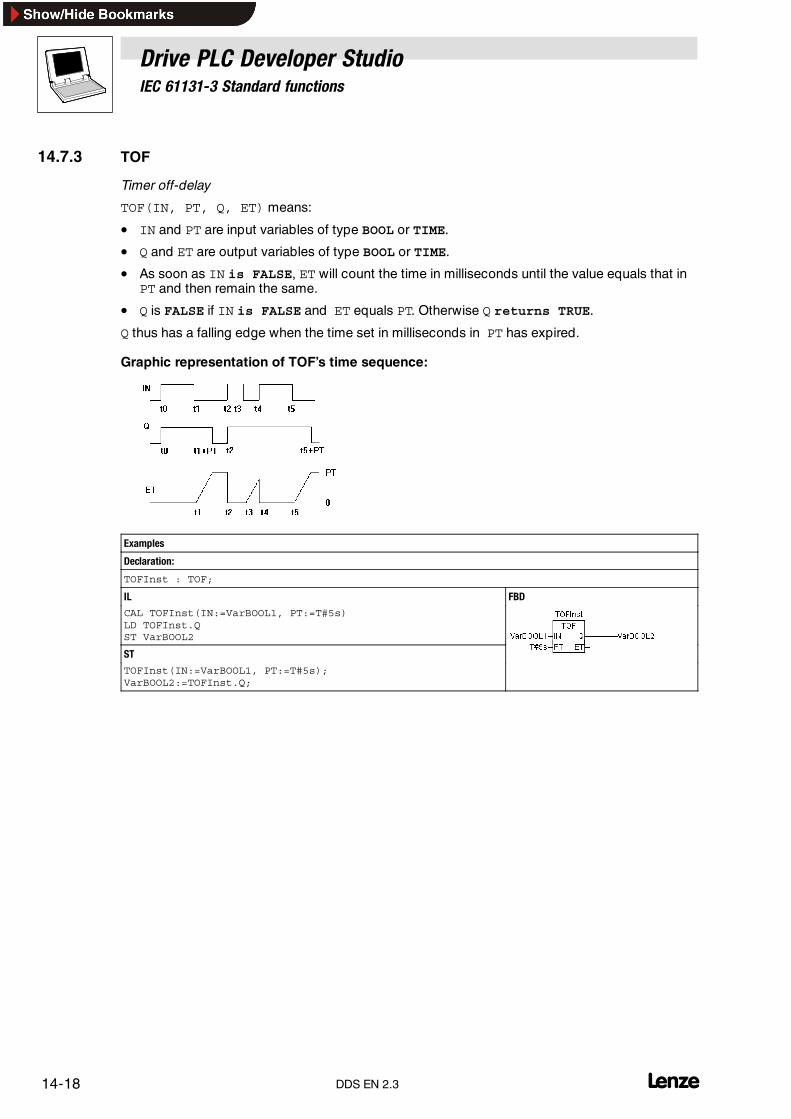
Drive PLC Developer StudioIEC 61131-3 Standard functions
14-18 lDDS EN 2.3
14.7.3 TOF
Timer off-delay
TOF(IN, PT, Q, ET) means:
• IN and PT are input variables of type BOOL or TIME.
• Q and ET are output variables of type BOOL or TIME.
• As soon as IN is FALSE, ET will count the time in milliseconds until the value equals that inPT and then remain the same.
• Q is FALSE if IN is FALSE and ET equals PT. Otherwise Q returns TRUE.
Q thus has a falling edge when the time set in milliseconds in PT has expired.
Graphic representation of TOF’s time sequence:
Examples
Declaration:
TOFInst : TOF;
IL FBD
CAL TOFInst(IN:=VarBOOL1, PT:=T#5s)LD TOFInst.QST VarBOOL2
ST
TOFInst(IN:=VarBOOL1, PT:=T#5s);VarBOOL2:=TOFInst.Q;

Drive PLC Developer StudioAppendix
15-1l DDS EN 2.3
15 Appendix
15.1 Command line commands
The DDS can be assigned certain commands on startup that will become effective on programexecution. These command line commands start with ” /” and are case-insensitive. Processing issequential from left to right.
/online DDS attempts to go online with the current project after startup.
/run DDS starts the user program after log-in.Valid in combination with /online only.
/show/show hide/show icon/show max/show normal
The DDS frame window display can be set.The window is not displayed and does not show in the task bar.The window is minimized.The window is maximized.The window is shown in the status applicable on last exit.
/out <outfile> All messages are output into the message window and the file <outfile>.
/cmd <cmdfile> After startup, the commands in command file <cmdfile> will be executed.
A command line input is structured as follows:”<DDS EXE file path>” ”<Project path>” / <Command 1> / <Command 2> ...
DDS file *.pro is opened, the window is not displayed. The content of command file (cmdfile)command.cmd is processed.

Drive PLC Developer StudioAppendix
15-2 lDDS EN 2.3
15.2 Command file (Cmdfile) commands
The commands that may be used within a command file <cmdfile> are listed as follows. The file canthen be called via the command line (see above). Input is case-insensitive.The command line isoutput as a message in the message window in the message file (see below), preceded, in additionto the command, by an ”@” . All characters behind a semicolon (;)are ignored (comment). Any whitespaces in parameters require the respective parameters to be put in quotes.
Online menu commands
online login Log in with the loaded project Online�Log in
online logout Log out Online�Log out
online run Start the user program Online�Log in
online sim Activate simulation (�) Online �Log in
online sim off Deactivate simulation Online�Simulation
Menu File commands
file new Create a new project File�New
file open <projectfile> Load the specified project File�Open
file close Close the loaded project. File �Close
file save Save the loaded project File�Save
file saveas <projectfile> Save the loaded project under the specified name File�Save as
file quit Exit DDS File �Exit
Menu Project commands
project compile orproject build Incrementally compile the loaded project Project�Compile
project rebuild Completely compile the loaded project Project�Compile all
project clean Deletes compile and download information in the current projectProject �Clean all
project import<file 1>...<file n>
Import the specified files <file1> ... <file n> into the loaded project Project�Import
project export <expfile> Export the loaded project into the specified file <expfile> Project�Export
project expmul <dir> Export every object of the loaded project into the directory <dir> into a separate file, each bearing the object’sname.
Manage message file
out open <msgfile> Open the specified file for message output. New messages will be attached
out close Close the currently open message file
out clear Clear all messages from the currently open message file
Manage message output
echo on Also output command lines as message
echo off Do not output command lines as message
echo <text> Output the <text> as message
Manage the replacement of objects or files during Import, Export, Replace
replace okreplace yes Replace
replace no Do not replace
replace yesall Replace all
replace noall Replace none

Drive PLC Developer StudioAppendix
15-3l DDS EN 2.3
Manage the default behaviour of DDS dialogs
query on Display dialogs expecting user input
query of ok All dialogs behave in accordance with a click on OK
query off no All dialogs behave in accordance with a click on No
query off cancel All dialogs behave in accordance with a click on Cancel
Command to call command files as subroutines
call <parameter 1>...<parameter 10>
Call command files as subroutines. Up to 10 parameters may be transferred. In the called file, $0 - $9 may beused to access the parameters.
Set used DDS directories
dir lib <libdir> Set <libdir> as the library directory
dir compile <compiledir> Set <compiledir> as compilation file directory
Delay CMDFILE processing
delay 5000 Wait 5 seconds (accuracy of execution in 100ms steps)
Manage the Watch and Receipt Manager
watchlist load <file> Loads the Watch list saved under <file> and opens the associated window Extras�Load Watch list
watchlist save <file> Saves the current Watch list under<file> Extras�Save Watch list
watchlist set <text> Assign the name <text> to a previously loaded Watch list Extras�Rename Watch list
watchlist read Update the Watch variable values Extras�Read Receipt
watchlist write Assign the Watch variables with the values in the Watch list Extras�Write Receipt
Integrate libraries
library add<libraryfile 1><libraryfile 2>...<libraryfile n>
Attach the specified library files to the library list of the currently open project. If the file path is relative, the librarydirectory set in the project will be set as the path root.
library delete[<library 1><library 2>...<library n>]
Delete all libraries or the specified one from the library list of the currently open project.
Copy objects
object copy<Source project file><Source path><Target path>
Copy objects from the specified path of the source project file into the target path of the currently open project.If the source path is the name of an object, that object will be copied. If it is a folder, all objects under this folderwill be copied. In this case, the folder structure under the source folder will be accepted.If the target path does not yet exist, it will be generated.
Set the communication parameters (gateway, device)
gateway local Set the gateway of the local processor as the current gateway
gateway tcpip<Address><Port>
Set the gateway set in the specified remote processor as the current gateway<Address>: TCP/IP address or host name of the remote processor<Port>: TCP/IP port of the remote gatewayCaution:Only those gateways without a set password can be accessed!
device guid<guid>
Set the device with the specified GUID as the current device.The GUID must correspond to the following format:{01234567-0123-0123-0123-0123456789ABC}The curly brackets and hyphens must be located at the specified positions.
device name<devicename>
Set the device with the specified name as the current device.

Drive PLC Developer StudioAppendix
15-4 lDDS EN 2.3
Set the communication parameters (gateway, device)
device instance<Instance name> Set the instance name for the current device to the specified name.
device parameter<Id>|<paramtername><value>
Assign the parameter with the specified ID, or optionally the specified parameter name, the specified value thatwill then be interpreted by the device.
System call
system <Command> Execute the specified operating system command.
Select automation system
target <Id>|<name> Set the target platform for the current project. Specification of target ID or optionally the target name, as specifiedin the target file.
Command file command.cmd
file open C:\projects\DDS_test\ampel.proquery off okwatchlist load c:\work\w.wtconline loginonline rundelay 1000watchlist readwatchlist save c:\work\watch.wtconline logoutfile close
This command file
• opens the project file ampel.pro
• loads a Watch list loaded under w.wtc
• starts the user program
• after one second writes the variable values into the Watch list watch.wtc that is saved
• and then closes the project again.
The command file is called as follows in the command line:
”<Path DDS file>” ”<Path cmd file>”
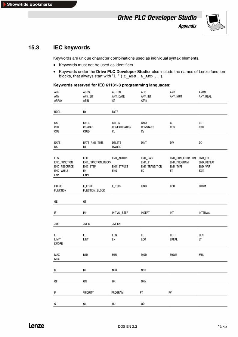
Drive PLC Developer StudioAppendix
15-5l DDS EN 2.3
15.3 IEC keywords
Keywords are unique character combinations used as individual syntax elements.
• Keywords must not be used as identifiers.
• Keywords under the Drive PLC Developer Studio also include the names of Lenze functionblocks, that always start with ”L_” ( L_ABS , L_ADD , ...).
Keywords reserved for IEC 61131-3 programming languages:
ABS ACOS ACTION ADD AND ANDNANY ANY_BIT ANY_DATE ANY_INT ANY_NUM ANY_REALARRAY ASIN AT ATAN
BOOL BY BYTE
CAL CALC CALCN CASE CD CDTCLK CONCAT CONFIGURATION CONSTANT COS CTDCTU CTUD CU CV
DATE DATE_AND_TIME DELETE DINT DIV DODS DT DWORD
ELSE ESIF END_ACTION END_CASE END_CONFIGURATION END_FOREND_FUNCTION END_FUNCTION_BLOCK END_IF END_PROGRAM END_REPEATEND_RESOURCE END_STEP END_STRUCT END_TRANSITION END_TYPE END_VAREND_WHILE EN ENO EQ ET EXITEXP EXPT
FALSE F_EDGE F_TRIG FIND FOR FROMFUNCTION FUNCTION_BLOCK
GE GT
IF IN INITIAL_STEP INSERT INT INTERVAL
JMP JMPC JMPCN
L LD LDN LE LEFT LENLIMIT LINT LN LOG LREAL LTLWORD
MAX MID MIN MOD MOVE MULMUX
N NE NEG NOT
OF ON OR ORN
P PRIORITY PROGRAM PT PV
Q Q1 QU QD

Drive PLC Developer StudioAppendix
15-6 lDDS EN 2.3
R R1 R_TRIG READ_ONLY READ_WRITE REALRELEASE REPEAT REPLACE RESOURCE RET RETAINRETC RETCN RETURN RIGHT ROL RORRS RTC R_EDGE
S S1 SD SEL SEMA SHLSHR SIN SINGLE SINT SL SQRTSR ST STEP STN STRING STRUCTSUB
TAN TASK THEN TIME TIME_OF_DAY TOTOD TOF TON TP TRANS TRUETYPE
UDINT UINT ULINT UNTIL USINT
VAR VAR_ACCESS VAR_EXTERNAL VAR_GLOBAL VAR_INPUT VAR_IN_OUTVAR_OUTPUT
WHILE WITH WORD
XOR XORN

Drive PLC Developer StudioAppendix
15-7l DDS EN 2.3
15.4 Key combinations and function keys
The available key combinations and function keys are listed as follows:
General operation
Function Keyboard command
Toggle between declaration and instruction parts of an organization unit <F6>
Toggle between Object Organizer , object and message window <Alt>+<F6>
Shortcut menu <Umschalt>+<F10>
Short form mode for declarations <Ctrl>+<Enter>
Open and close multi-level variables <Enter key>
Open and close folders <Enter key>
Move among tab cards in the Object Organizer and Library Manager <Arrow keys>
Jump in dialogs <Tab>
Context-sensitive help <F1>
General commands
Menu command Keyboard command
File � Save <Ctrl>+<S>
File � Print <Ctrl>+<P>
File � Exit <Alt>+<F4>
Project � Delete object <Del>
Project � Insert object <Ins>
Project � Rename object <Space bar>
Project � Edit object <Enter key>
Project � Check all <Ctrl>+<F11>
Project � Compile all <F11>
Edit � Undo <Ctrl>+<Z>
Edit � Redo <Ctrl>+<Y>
Edit � Cut <Ctrl>+<X> or <Umschalt>+<Del>
Edit � Copy <Ctrl>+<C>
Edit � Insert <Ctrl>+<V>
Edit � Delete <Del>
Edit � Find next <F3>
Edit � Help Manager <F2>
Edit � Next fault <F4>
Edit � Previous fault <Umschalt>+<F4>
Online � Log-in <Alt>+<F8>
Online � Log-out <Ctrl>+<F8>
Online � Start <F5>
Online � Stop <Umschalt>+<F8>
Online � Breakpoint on/off <F9>
Online � Single step over <F10>
Online � Single step in <F8>
Online � Single cycle <Ctrl>+<F5>
Online � Write values <Ctrl>+<F7>
Window � Messages <Umschalt>+<Esc>

Drive PLC Developer StudioAppendix
15-8 lDDS EN 2.3
FBD editor commands
Menu command Keyboard command
Insert � Network (after) <Ctrl>+<T>
Insert � Assignment <Ctrl>+<A>
Insert � Jump <Ctrl>+<L>
Insert � Return <Ctrl>+<R>
Insert � Operator <Ctrl>+<O>
Insert � Function <Ctrl>+<F>
Insert � Function block <Ctrl>+<B>
Insert � Input <Ctrl>+<U>
Extras � Negation <Ctrl>+<N>
Extras � Zoom <Alt>+<Enter>
LD editor commands
Menu command Keyboard command
Insert � Network (after) <Ctrl>+<T>
Insert � Contact <Ctrl>+<O>
Insert � Parallel contact <Ctrl>+<R>
Insert � Function block <Ctrl>+<B>
Insert � Coil <Ctrl>+<L>
Extras � Paste below <Ctrl>+<U>
Extras � Negation <Ctrl>+<N>
SFC editor commands
Menu command Keyboard command
Insert � Step transition (before) <Ctrl>+<T>
Insert � Step transition (after) <Ctrl>+<E>
Insert � Alternative branch (right) <Ctrl>+<A>
Insert � Parallel branch (right) <Ctrl>+<L>
Insert� Jump <Ctrl>+<U>
Extras � Zoom action/transition <Alt>+<Enter>
Change from SFC overview back to editor <Enter>
CFC editor commands
Menu command Keyboard command
Insert � Box <Ctrl>+<B>
Insert � Input <Ctrl>+<E>
Insert � Output <Ctrl>+<A>
Insert � Jump <Ctrl>+<J>
Insert � Label <Ctrl>+<L>
Insert � Return <Ctrl>+<R>
Insert � Comment <Ctrl>+<K>
Insert � Box input <Ctrl>+<U>
Extras � Negation <Ctrl>+<N>
Extras � Set/Reset <Ctrl>+<T>
Extras � EN/ENO <Ctrl>+<O>

Drive PLC Developer StudioAppendix
15-9l DDS EN 2.3
Operation of PLC configuration
Function Keyboard command
Open and close organization elements <Enter>
Draw edit frame around the name <Space bar>
Operation of task configuration
Function Keyboard command
Draw edit frame around task or program name <Space bar>

Drive PLC Developer StudioAppendix
15-10 lDDS EN 2.3
15.5 Error messages
The DDS will display the following error messages in alphabetical sequence in the message windowafter a log-in or compile.
Note!Contact your Lenze representative for any error message not described in this chapter.
15.5.1 Warnings
No. Cause Possible remedy1100 Unknown function <Name> in library. You are using an external library. Check that all functions in the .hex file are also defined in
the .lib file.1101 Unresolved icon <Icon>. The code generator expects an organization unit named <Icon> that has not been defined in
the project. Define a function / program with the relevant name.1102 Incorrect interface for icon <Icon>. The code generator expects a function named <Icon> and with a scalar input or a program
named <Icon> without input or output.1103 The constant %s at code address <%04X %04X> is above
a 16K page limit!A string constant is above the 16K page limit.The system cannot handle this. Depending onthe runtime system, there may be an option to avoid this from happening by making an inputin the target file. Contact the control manufacturer.
1200 Task %s: Call of %s access variables in the parameter listnot updated.
Variables that are used only for a function block call in the task configuration are notincluded in the cross reference list.
1300 File <Name> not found The file referenced by the global variable object does not exist. Check the path.1301 Analysis library not found.
Analysis code not generated.You are using the Analyze function although the library analyzation.lib is missing.Insert the library into the Library Manager.
1302 New externally referenced functions inserted.Online change is no longer possible!
Since the last download, you have integrated a library with functions that have not beenreferenced yet in the runtime system so that the whole project must be downloaded.
1400 Unknown compiler directive <Name> is ignored! The compiler does not support this pragma.Refer index word Pragma for supported directives.
1401 The structure <Name> contains no elements. The structure contains no elements, although variables of this type take up 1 Byte memory.1500 This expression contains no assignment.
No code generated.The result of this expression is not used so that no code is generated for the completeexpression.
1501 String constant transferred as VAR_IN_OUT:<Name> must not be overwritten!
The constant must not be written in the body of the organization unit as no size check ispossible there.
1502 Variable <Name> bears the same name as an organizationunit.The organization unit is not called!
You are using a variable that bears the same name as an organization unit.PROGRAM aVAR_GLOBAL
a: INT;END_VAR...a; (* The process does not call organization unit a, but loads variable a.*)
1503 The organization unit has no outputs, connection continuedwith TRUE.
You are connecting the output pin of an organization unit without outputs further in FBD orLD. The connection is automatically assigned the value TRUE.
1504 Instruction not executed, possibly dependent on logicalexpression.
It is possible that not all branches of the logical expression are executed.IF a AND funct(TRUE) THEN...If a = FALSE, funct will no longer be called.
1505 Side effect in <Name>! Branch will possibly not becomputed
The first input of the organization unit is FALSE, so that the side branch entering at thesecond input is possibly no longer computed.
1506 Variable %s bears the same name as a local action.The action is not called.
Rename the variable or the action to avoid identical names.
1600 Open DB unclear (generated code may be incorrect). The original Siemens program does not reveal which data block is open.1700 Input not connected. You are using an input box in the CFC that is not connected further.
No code will be generated for this.1800 <Name>(Element #<Element number>): Incorrect Watch
expression <Name>The visualization element contains an expression that cannot be monitored. Check variablename and placeholder substitutes.
1801 No entry possible to expression. You are using a composite expression as the target of an entry action in the visualizationobject configuration.Replace this with a single variable.
1900 The POU <Name> (entry function) is not available in thelibrary.
The entry organization unit (e. g. PLC_PRG) will not be available during library use.

Drive PLC Developer StudioAppendix
15-11l DDS EN 2.3
No. Possible remedyCause1901 Access variables and configuration variables are not saved
in a library!Access variables and variable configurations are not saved in the library.
1902 <Name>: Library not suitable for the current machine type! The .obj file of the library was generated for a different machine type.1903 <Name>: Incorrect library The file does not correspond to the file format required by the automation system.2900 A system organization unit was used in a scale function. It
is possible that no process image will be generated for thissystem organization unit.Chapter on Scale functions (� 8-18).
Ensure with the help of the process image monitor that a process image is generated for theapplied system organization unit. � 8-20
2901 A system organization unit was used in a system POU. It ispossible that no process image will be generated for thissystem organization unit.Chapter System POUs in the automation systemdocumentation (� 2-7)
Ensure with the help of the process image monitor that a process image is generated for theapplied system organization unit.Caution!Even if a process image is generated, some system POUs may cause problems if the data donot exist yet at the time of processing.
2902 Invalid target path for the GDC device description.An error occurred during generation of the GDC devicedescription. For the error cause refer to the transmittederror code:100: No valid name for the device description200: Basic device description could not be opened300: Error in basic device description
100:Use Project�Options category Device description to specify a different path.
200, 300:Deinstall the DDS and correctly reinstall it.If the error still occurs, please contact your Lenze representative.
2903 A user code is using an unknown unit. Define the applied unit in the Instance Parameter Manager. � 8-112904 The code reference to an organization unit could not be
resolved.The organization unit was deleted.
2905 The binary file project name.bin (*.bin) could not becreated.
The *.bin file may be write-protected. Remove the write protection.
15.5.2 Compile errors
No. Cause Possible remedy3100 Program too large.
Maximum size: <Number> byte (<Number>K)Maximum program size exceeded.Reduce program size.
3101 Data area too large.Maximum size: <Number> byte (<Number>K)
The data memory is full.Reduce your applications data requirement.
3110 Error in library file <Name>. The .hex file does not correspond to the INTEL hex format.3111 Library <Name> is too big. Maximum size: 64K The .hex file exceeds the maximum possible size.3112 Irrelocatable instruction in library. The .hex file contains an irrelocatable instruction.
The library code can not be linked.3113 Library code overwriting function tables. The code and information table sections overlap.3114 Library uses more than one segment. The tables and code in the .hex file use more than one segment.3115 Constant cannot be assigned to VAR_IN_OUT. Incompatible
data types.The internal pointer format for string constants cannot be converted into the internal pointerformat of VAR_IN_OUT as the data are defined as near and the string constants as huge orfar.Change these automation system settings if possible
3120 Current code segment in excess of 64K. The system code just generated is in excess of 64K.The system possibly requires too much initialization code.
3121 Organization unit too big. An organization unit must not exceed 64K.3122 Initialization too large. Maximum size: 64K The initialization code for a function block or a structure must not exceed 64K.3130 Application stack too small:
<Number> DWORD required<Number> DWORD available.
The organization unit calls are nested too deeply. Enlarge the stack size in the automationsystem settings, or compile the program without the project compile option Debug.
3131 User stack too small:<Number> WORD required, <Number> WORD available.
Contact the control manufacturer.
3132 System stack too small:<Number> WORD required, <Number> WORD available.
Contact the control manufacturer.
3150 Parameter %d of function <Name>:The result of an IEC function cannot be transferred to a Cfunction as string parameter.
Use an intermediate variable.Transfer the result of an IEC function to the variable.
3160 Cannot open library file <Name>. The file <Name> required for a library cannot be found.3161 Library <Name> contains no code segment An .obj file of a library must contain at least one C function.
Insert a dummy function into the .obj file, that is not defined in the .lib file.3162 Cannot resolve reference in library <Name> (Icon
<Name>, Class <Name>, Type <Name>)The .obj file contains an irresolvable reference to another icon.Check the C compiler settings.

Drive PLC Developer StudioAppendix
15-12 lDDS EN 2.3
No. Possible remedyCause3163 Unknown reference type in library <Name>
(Icon <Name>, Class <Name>, Type <Name>)The .obj file contains a reference type the code generator cannot resolve.Check the C compiler settings.
3200 <Name> (%d): Logical expression too complex. The temporary memory of the automation system is insufficient to cope with the size of theexpression.Divide the expression into several part expressions with assignments to intermediatevariables.
3201 <Name> (<Network>): A network may return a maximumof 512 byte code.
Internal jumps cannot be resolved.Activate the option Use 16 bit jump offsets in the 68k target settings.
3202 Stack overflow on nested string/array/structure functioncalls.
You are using a nested form CONCAT(x, f(i)) function call. This may lead to data loss. Split thecall into two expressions.
3203 Assignment too complex (too many address registersrequired)
Split the assignment.
3204 A jump is in excess of 32k bytes. Jump distances must not exceed 32767 bytes.3205 Internal error: Too many constant strings A maximum of 3000 string constants may be used within one organization unit.3206 Function block too large A function block may return a maximum of 32767 bytes code.3207 Array optimization
Unsuccessful array access optimization.A function was called within the index computation.
3208 Conversion not implemented You are using a conversion function that is not implemented for the current code generator.3209 Operator not implemented You are using an operator that is not implemented for this data type in the current code
generator: MIN(string1,string2).3210 Function <Name> not found You are calling a function that does not exist within the project.3211 String variable used too often A string-type variable must only be used ten times in an expression with the 68K code
generator.3250 Real not supported on 8 bit controller. The automation system is currently not supported.3251 Date-of-day types not supported on 8 bit controller. The automation system is currently not supported.3252 Stack size in excess of %ld bytes. The automation system is currently not supported.3253 Hex file not found: <Name> The automation system is currently not supported.3254 Call of an external library function could not be resolved. The automation system is currently not supported.3400 Error on access variable import. The .exp file contains an incorrect access variable section.3401 Error on Configuration variable import. The .exp file contains an incorrect configuration variable section.3402 Error on global variable import. The .exp file contains an incorrect global variable section.3403 <Name> could not be imported. The section in the .exp file for the specified object is incorrect.3404 Error on Configuration Task import. The section in the .exp file for the Configuration Task is incorrect.3405 Error on PLC configuration import. The section in the .exp file for the PLC configuration is incorrect.3406 Two steps named <Name>.
The second step was not imported.The SFC organization unit section contained in the .exp file includes two steps with identicalnames. Rename one of the steps in the export file.
3407 Input step <Name> not found The named step is missing in the .exp file.3408 Subsequent step <Name> not found The named step is missing in the .exp file.3409 No subsequent transition for step <Name> A transition requiring the named step as the entry step, is missing in the .exp file.3410 No subsequent step for transition <Name> A step requiring the named transition is missing in the .exp file.3411 Step <Name> cannot be accessed from Init Step The link between the named step and the Init Step is missing in the .exp file.3450 PDO<Name>: <Module name> <Configuration dialog
name> <PDO Name> COB-Id missing!Click the button Properties in the configuration dialog <Configuration dialog name> ofmodule <Module name> and enter a COB ID for PDO <PDO Name>.
3451 Loading error: EDS file <Name> could not be found, but isused in the configuration!
The device file required for CAN configuration may possibly not be available in the correctdirectory. Check the directory entry for configuration files in Project�Options categoryDirectories.
3452 The module <Name> could not be generated! The device file for module <Name> no longer suits the current configuration. It may havebeen changed since the original configuration, or be corrupted.
3453 Channel <Name> could not be generated! The device file for channel <Name> no longer suits the current configuration. It may havebeen changed since the original configuration, or be corrupted.
3454 The address <Name> references an assigned memorylocation!
You have activated the option Check for overlapping addresses in dialog Settings of thePLC configuration, and an overlap was found. Note that the range check is based on the sizeresulting from the module data type, and not the value in the entry Size in the configurationfile!
3455 Loading error: GSD file <Name> could not be found, but isused in the configuration!
The device file required for Profibus configuration may possibly not be available in thecorrect directory. Refer entry for configuration files in Project�Options categoryDirectories.
3456 The Profibus device <Name> could not be generated! The device file for device <Name> no longer suits the current configuration. It may havebeen changed since the original configuration, or be corrupted.
3457 Incorrect module description: <Name>! Check the device file pertaining to the module.3500 No VAR_CONFIG for <Name> Insert a declaration for the named variable in the global variable list with
Variable_Configuration. Resources�Global_Variables � 8-2

Drive PLC Developer StudioAppendix
15-13l DDS EN 2.3
No. Possible remedyCause3501 No address in VAR_CONFIG for <Name> Insert an address for the named variable in the global variable list with
Variable_Configuration. Ressourcen�Global_Variables � 8-23502 Wrong data type of <Name> in VAR_CONFIG The named variable was declared in the global variable list (with Variable configuration) with
a different data type than in the function block.3503 Wrong address type of <Name> in VAR_CONFIG The named variable was declared in the global variable list (with Variable configuration) with
a different address type than in the function block.3504 Initial values for VAR_CONFIG variables are not supported A Variable Configuration variable has been declared with address and initial value. However,
an initial value can be defined only for input variables without address assignment.3505 <Name> is no valid instance path A non-existent variable was specified in the variable configuration.3506 Access path expected A correct access path is missing for one variable in the global variable list for access
variables:<Identifier>:’<Access path>’:<Type> <Access type>
3507 No address specification permitted for VAR_ACCESS An address assignment exists for one variable in the global variable list for access variables.Correct definition:<Identifier>:’<Access path>’:<Type> <Access type>
3550 The task name <Name> was used twice You have defined two tasks with the same name.Rename one of them.
3551 The task <Name> must contain at least one program call Insert a program call, or delete the task.3552 Event variable <Name> in task <Name> not defined You have used an event variable in the configuration of the named task, that is not globally
declared in the project.Use a different variable or define the entered variable globally.
3553 Event variable <Name> in task <Name> must beBOOL-type
Use a BOOL-type variable as event variable.
3554 Task entry <Name> must be a program or a globalfunction block instance.
You have entered a function or an undefined organization block in the field Program call.
3555 The task entry <Name> is parameterized incorrectly You have specified parameters in the field Program call that do not correspond to thedeclaration of the organization block.
3600 Implicit variable not found. First use the command Compile all. Contact the control manufacturer if the error messagereappears.
3601 <Name> is a reserved variable name. You have declared a variable in the project that is already reserved for the code generator.Rename this variable.
3610 <Name> not supported The named feature is not supported by this version.3611 The compile directory <Name> is incorrect. You have entered an incorrect directory for the compile files in the Project�Options
Category Directories.3612 Maximum number of organization units (<Number>)
exceeded! Compile will be aborted.You are using too many organization units and data types in the project.Change the maximum number of organization units in dialog box Automation system settingstab Memory layout.Note!The tab memory layout cannot be edited at the moment.
3613 Compile terminated The user terminated the compile.3614 The project contains no organization unit <Name> (entry
function) or task configurationA project requires a Program-type entry function (e.g. PLC_PRG) or a task configuration.
3615 <Name> (entry function) must be Program-type. You are using an entry function (e. g. PLC_PRG) other than Program-type.3616 Programs in external libraries are not supported The library to be saved contains a program that will not be available during library use.3617 Insufficient memory Increase the virtual memory capacity of your processor.3618 The current code generator does not support bit access The code generator for the currently set automation system does not support bit access to
variables.3700 An organization unit named <Name> already exists in
library <Name>You are using an organization unit name that has already been assigned for a libraryorganization unit. Rename the organization unit.
3701 The organization unit name in the declaration name doesnot match the name in the object list.
Rename your organization unit using the menu commands Project�Rename object orchange the name of the organization unit in its declaration part. The name must appeardirectly after the keywords Program, Function or Function block.
3702 Too many identifiers A maximum of 100 identifiers may be specified per variable declaration.3703 Several declarations with the same identifier <name> Several identically named identifiers exist in the object’s declaration part.3705 Data recursion: <Organization unit 0> �
<Organization unit 1> � ... � <Organization unit 0>An FB instance was used that requires itself to function.
3720 AT must be followed by an address. Insert a valid address after the keyword AT or change the keyword AT.3721 Only VAR and VAR_GLOBAL can be assigned to addresses. Copy the declaration to a VAR or VAR_GLOBAL section.3722 Only simple Boolean variables may be located at the
specified address.Change the address or the variable type stated in the declaration.
3722 Only simple Boolean variables may be located at thespecified address.
Change the address or the variable type stated in the declaration.
3728 PLC_PRG(): Impermissible address %IX141.58.0. Specify a correct address.

Drive PLC Developer StudioAppendix
15-14 lDDS EN 2.3
No. Possible remedyCause3740 Unknown type: <Name> You are using an incorrect type for variable declaration.3741 Type identifier expected You are using a keyword or an operator instead of a correct type identifier.3742 Enumeration value expected An identifier is missing behind the left parenthesis, or behind a comma within the area in
parentheses, in the definition of the enumeration type.3743 Integer expected Enumeration values can only be initialized with INT-type integers.3744 Enumeration constant <Name> already defined Check that you have observed the following rules while assigning enumeration values.
• All values must be unique within one enumeration definition.• All values must be unique within all global enumeration definitions.• All values must be unique within all local enumeration definitions of an organization unit.
3745 Range delimiters are permitted for integer data types only! Subrange types may be defined based on integer data types only.3746 Range delimiter <Name> incompatible with data type
<Name>A limit for the range specified for the subrange type is outside the limits permitted for thebasic type.
3747 Unknown string length: <Name> You are using an unknown constant to define the string length.3748 More than 3 dimensions are impermissible for one array You are using in excess of the permissible 3 dimensions for an array.
Use an ARRAY OF ARRAY as required.3749 Lower range limit <Name> unknown You are using an undefined constant as the lower range limit of a subrange or array type.3750 Upper range limit <Name> unknown You are using an undefined constant as the upper range limit of a subrange or array type.3760 Incorrect initial value
bzw. Initialisierung von Pointernpt:POINTER TO<typ>:= ADR(variable); nicht möglich
Use an initial value that corresponds to the type definition.Use the variable declaration dialog for assistance.Shift+F2 or Edit�Variable configurationGrundsätzlich sollten Pointer vermieden werden.Beachten Sie auch im Kapitel Datentypen den Abschnitt Pointer. � 10-4
3761 VAR_IN_OUT variables must have no initial value. Remove the initialization in the variable declaration.3780 VAR, VAR_INPUT, VAR_OUTPUT or VAR_IN_OUT expected The first line after an organization unit name must contain one of these keywords.3781 END_VAR or identifier expected Insert a valid identifier or END_VAR at the beginning of the declaration line.3782 Unexpected end Declaration part:
Insert the key word END_VAR at the end of the declaration part.Text editor:Insert instructions that end the last instruction sequence (END_IF, for example).
3783 END_STRUCT or identifier expected Ensure that the type declaration is completed properly3800 The global variables require too much memory. Increase
the available memory in the project optionsIncrease the number of segments set in the build options in the project options.
3801 Variable <Name> is too big. (<Size> byte) The variable is using a type larger than 1 data segment. Dependent on the automationsystem, the segment size can be defined in dialog box Automation system settings tabMemory layout. Contact the control manufacturer if you find no entry option there.
3802 Memory for Retain variables used up.Variable <Name>, %u byte.
The available memory area for Retain variables is exhausted. Dependent on the automationsystem, the memory area can be defined in dialog box Automation system settings tabMemory layout. Contact the control manufacturer if you find no entry option there.Note!Also that in the case of instances of function blocks in which a Retain variable is used, theRetain memory manages the complete instance.
3803 Memory area for global variables exhausted. Variable<Name>, <Number> byte.
The memory area available for global variables is exhausted.• The available memory area depends on the target system.• Information about the memory area available for the target system is given in the dialog
box Target settings, tab Memory layout.3820 VAR_OUTPUT and VAR_IN_OUT not allowed in functions. You must not define any output / reference parameters in a function.3821 At least one input required for a function Insert at least one input parameter for the function.3840 Unknown global variable <Name>. You are using a VAR_EXTERNAL variable in the organization unit, for which no associated
global variable has been declared.3841 Declaration of <Name> does not match global declaration! The type specified in the declaration of the VAR_EXTERNAL variable does not match that in
the global declaration.3900 Multiple underscores in the identifier. Remove multiple underscores in the identifier name.3901 Max. 4 address fields allowed. You are using a direct address assignment to an address that contains in excess of four
levels (e. g %QB0.1.1.0.1).3902 Keywords must be written in uppercase Write the keyword in uppercase or activate the option Autoformat.3903 Incorrect time constant The constant is not specified in accordance with the IEC 61131-3 format.3904 Time constant overflow You are using a value for the time constant that can no longer be represented within the
internal format. The maximum representable value is t#49d17h2m47s295ms.3905 Incorrect date constant The constant is not specified in accordance with the IEC 61131-3 format.3906 Incorrect time-of-day constant The constant is not specified in accordance with the IEC 61131-3 format.3907 Incorrect date/time constant The constant is not specified in accordance with the IEC 61131-3 format.3908 Incorrect string constant The string constant includes an incorrect character.4000 Identifier expected Enter a correct identifier here.

Drive PLC Developer StudioAppendix
15-15l DDS EN 2.3
No. Possible remedyCause4001 Variable <Name> not declared Declare the variable locally or globally.4010 Incompatible types: Cannot convert <Name> into <Name>. Check the required operator types and change the type of the variable that caused the error
into a permissible type, or select a different variable.4011 Impermissible type in parameter <Parameter> of <Name>:
Cannot convert <Name> into <Name>.The actual parameter type cannot be converted into the formal parameter type. Use a typeconversion or a suitable variable type.
4012 Impermissible type for input <Name> of <Name>:Cannot convert <Name> into <Name>.
The variable <Name> is assigned a value of an impermissible type <Type2>. Change thevariable or the constant into a variable or constant of type <Type1> or use a type conversionor a constant with a type prefix.
4013 Impermissible type for output <Name> of <Name>:Cannot convert <Name> into <Name>.
The variable <Name> is assigned to a value of an impermissible type <Type2>. Change thevariable or the constant into a variable or constant with type <Type1> or use a typeconversion or a constant with a type prefix.
4014 Constant with type prefix: <Name> cannot be converted to<Name>.
The constant type is incompatible with the prefix type. Example: SINT#255
4015 Impermissible data type <Name> for direct bit access Direct bit addressing is permitted for integer and bitstring data types only. You are using atype REAL/LREAL variable var1 in bit access <var1>.<bit> or a constant.
4016 Bit index <%d> outside the valid range for <Name>-typevariables
You are attempting access to a bit that is not defined for the variable’s data type.
4017 MOD is not defined for REAL The operator MOD can be used for integer and bitstring data types only.4020 ST, STN, S, R operands must be write-access variables Replace the first operand with a variable with write access.4021 No write access to <Name> Replace the variable with one with write access.4022 Operand expected Add an operand behind the existing command.4023 Number expected after ”+” or ”-”. Enter a number.4024 Expect <Operator 0> or <Operator 1> or ... in front of
<Name>Enter a correct operator at the named position.
4025 Expect := or => in front of <Name> Enter one of the two operators at the named position.4026 BITADR expects a bit address or a variable at a bit address Use a correct bit address (for example %IX0.1).4027 Integer or symbolic constant expected Insert an integer or the identifier of a correct constant.4028 INI operator requires a function block instance or a
structure variableCheck the type of the variable to which you apply the INI operator.
4029 Internested calls of the same function are not possible. In non-reentrant automation systems and in simulation mode, a function call must notcontain a call for itself as parameter.Example: fun1(a,fun1(b,c,d),e);Use an intermediate variable.
4030 No constants and expressions are allowed as ADR operands Replace the constant or the expression with a variable or a direct address.4031 The address operator is not permitted on bits ! Use BITADR.
BITADR returns no physical memory address.4032 <Number> operands insufficient for <Name>. At least
<number> are required.Check how many operands are required by the operator <Name> and insert the missingoperands.
4033 <Number> operands too high for <Name>. Exactly<number> are required.
Check how many operands are required by the operator <Name> and remove thesuperfluous operands.
4034 Division by 0 You are using a division by 0 in a constant expression. If necessary, use a value-0 variable toforce a runtime error.
4035 ADR must not be applied on VAR CONSTANT if Replaceconstants is active.
No address access is possible to constants for which the direct values are used. If required,deactivate the option Substitute constants in the project options, category Compilationoptions.
4040 Jump label <LabelName> is not defined Define a label named <LabelName> or change <LabelName> into a defined label.4041 Jump label <Name> defined more than once The label <Name> is defined more than once within the organization unit.
Rename it, or remove one definition.4042 The number of successive jump labels must be max.
<Number>The number of jump labels per instruction is limited to <Number>.Insert a dummy instruction.
4043 Incorrect label format:A label must be an identifier that may be followed by acolon.
The name used for the label is either no valid identifier, or the colon is missing in thedefinition.
4050 Organization unit <Name> does not exist in the project Define an organization unit named <Name> using the menu commandsProject�Insert object, or change <Name> to the name of a defined organization unit.
4051 <Name> is not a function. Use a function name defined in the project or in the libraries for <Name>.4052 <Instance name> must be a declared instance of function
block <Name>Use a type <Name> instance defined in the project for <Instance name>, or change the typefrom <Instance name> to <Name>.
4053 <Name> is no valid organization unit or operator Replace <Name> with the name of an organization unit or an operator defined in theproject.
4054 Organization unit name expected as parameter of INDEXOF The specified parameter is no valid organization unit name4060 VAR_IN_OUT parameter <Name> of <Name> requires
write-accessible variable as input.Write-accessible variables must be transferred to VAR_IN_OUT parameters as these can bemodified within the organization unit.

Drive PLC Developer StudioAppendix
15-16 lDDS EN 2.3
No. Possible remedyCause4061 VAR_IN_OUT parameter <Name> of <Name> must be
assigned.Write-accessible variables must be assigned to VAR_IN_OUT parameters as these can bemodified within the organization unit.
4062 No external access to VAR_IN_OUT parameter <Name> of<Name>.
VAR_IN_OUT parameters must only be written or read within the organization unit (referencetransfer).
4063 VAR_IN_OUT parameter <Name> of <Name> cannot beassigned bit addresses.
A bit address is no valid physical address.Transfer a variable or a direct non-bit address.
4064 VAR_IN_OUT must not be overwritten in local action call ! Delete the assignment of the VAR_IN_OUT variables for the local action call.4070 Too deeply nested expression in organization unit. Reduce the nesting depth by distributing the expression across several expressions with the
help of assignments to intermediate variables.4071 Network too large Divide the network into several networks.4100 ^ requires a pointer type You are attempting to dereference a variable that has not been declared as POINTER TO.4110 [<index>] only allowed for array variables You are using [<index>] for a variable that has not been declared as ARRAY OF.4111 The expression in the index of an array must have an
INT-type result.Use an expression of the respective type, or a type conversion.
4112 Too many array indices Check the number of indices (1, 2, or 3) for which the array has been declared, and removethe superfluous indices.
4113 Insufficient array indices Check the number of indices (1, 2, or 3) for which the array has been declared, and add themissing indices.
4114 Constant index outside array boundaries Ensure that the applied indices range within the array boundaries.4120 A ”.” must be preceded by a structure variable. The identifier to the left of the period must be a STRUCT or FUNCTION_BLOCK-type variable
or the name of a FUNCTION or a PROGRAM.4121 <Name> is no component of <Object name>. The component <Name> is not included in the definition of object <Object name>.4122 <Name> is not an input parameter of the called function
block.Check the input variables of the called function block, and change <Name> into one of thesevariables.
4200 LD expected Add at least one LD instruction in the editor window of the IL organization unit or behind thejump label.
4201 IL operator expected Every IL instruction must start with an operator or a jump label.4202 Unexpected end of the subexpression Insert the right parenthesis.4203 <Name> in parentheses not allowed The specified operator is not permitted within an IL subexpression.
(impermissible are: JMP, RET, CAL, LDN, LD, TIME)4204 Right parenthesis without left parenthesis. Insert left parenthesis, or delete right parenthesis.4205 No comma permitted after ) Remove the comma behind the right parenthesis.4206 No jump labels in subexpressions. Move the jump label outside the subexpression.4207 N modifier requires a BOOL, BYTE, WORD or DWORD-type
operand.The N modifier requires a data type for which a Boolean negation can be performed.
4208 The expression in front of a conditional command mustreturn a BOOL-type result
Ensure that the expression returns a Boolean result, or use a type conversion.
4209 Function names are not allowed here. Replace the function call with a variable or constant.4210 CAL, CALC and CALN require a function block instance as
an operandDeclare an instance of the function block to be called.
4211 Comments in IL at the end of the line only. Move the comment to the end of the line or into a separate line.4212 Accumulator invalid before conditional instruction The accumulator content is not defined.
This is the case after instructions that do not return any result (CAL, for example).4213 S and R require a BOOL-type operand Use a Boolean variable at this position.4250 No correct start for an ST instruction The line does not start with a correct ST instruction.4251 Function <name> has too many parameters. More parameters were specified than were declared in the function definition.4252 Function <name> has insufficient parameters. Fewer parameters were specified than were declared in the function definition.4253 IF and ELSIF require a Boolean expression as condition Ensure that the condition following an IF and ELSIF is a Boolean expression.4254 WHILE requires a Boolean expression as condition Ensure that the condition following a WHILE is a Boolean expression.4255 UNTIL requires a Boolean expression as condition Ensure that the condition following an UNTIL is a Boolean expression.4256 NOT requires a Boolean operand. Ensure that the condition following a NOT is a Boolean expression.4257 The counter of the FOR instruction must be INT-type Ensure that the counter variable is an integer or bitstring data type (DINT, DWORD, for
example).4258 The counter in the FOR instruction is no write-accessible
variableReplace the counter variable with a write-accessible variable.
4259 The start value of the FOR instruction must be INT-type. The start value of the FOR instruction must be compatible with the counter variable type.4260 The end value of the FOR instruction must be INT-type. The end value of the FOR instruction must be compatible with the counter variable type.4261 The incrementation value of the FOR instruction must be
INT-type.The incrementation value of the FOR instruction must be compatible with the countervariable type.
4262 EXIT is permitted only within a loop. Use EXIT only within FOR, WHILE or UNTIL instructions.4263 Number, ELSE or END_CASE expected Only a number or an ELSE instruction, or the end instruction END_CASE, can be specified
within a CASE.

Drive PLC Developer StudioAppendix
15-17l DDS EN 2.3
No. Possible remedyCause4264 The selector of the CASE instruction must be INT-type. Ensure that the selector is an integer or bitstring data type (DINT, DWORD, for example).4265 Number expected after, In the CASE selector list, another selector must be specified after a comma.4266 At least 1 instruction required. Enter an instruction, at least a semicolon.4267 A function block call must start with an instance name. The identifier in the function block call is no instance. Declare an instance of the required
function block, or use the name of an instance that has already been declared.4268 Expression expected Enter an expression at this position.4269 END_CASE expected after ELSE branch Complete the CASE instruction with an END_CASE after the ELSE branch.4270 CASE constant %ld already in use A CASE selector must be used once only within a CASE instruction.4271 The lower limit of the specified range is greater than the
upper limit.Correct the selector range limits so that the lower limit is not greater than the upper limit.
4272 Parameter <Name> expected at <Position> in <Name>call!
If the function parameters within the function call are specified with parameter names, theposition of the parameters (sequence) must match that in the function definition.
4273 CASE range <range limits> overlaps with already usedrange <range limits>
Ensure that the selector ranges specified in the CASE instruction do not overlap.
4274 Multiple ELSE branch in CASE instruction A CASE instruction must not contain in excess of one ELSE branch.4300 Jump or Return require a Boolean input Ensure that the input for the jump or the Return instruction is a Boolean expression.4301 Organization unit <Name> requires exactly <number>
inputsThe number of inputs does not match the number of VAR_INPUT and VAR_IN_OUT variablesspecified in the organization unit definition.
4302 Organization unit <name> requires exactly <number>outputs
The number of outputs does not match the number of VAR_OUTPUT variables specified in theorganization unit definition.
4303 <Name> is not an operator Replace <name> with a valid operator.4320 Non-Boolean expression <name> used for contact The switching signal for a contact must be a Boolean expression.4321 Non-Boolean expression <name> used for coil The output variable of a coil must be BOOL-type.4330 Expression expected at input EN of organization unit
<name>Assign the input EN of organization unit <name> with an input or an expression.
4331 Expression expected at input <number> %d of organizationunit <name>
The input of the operator organization unit is not assigned.
4332 Expression expected at input <name> of organization unit<name>
The input of the organization unit is VAR_IN_OUT-type and not assigned.
4333 Identifier expected in jump The specified jump target is no valid identifier.4334 Expression expected at jump input Assign the jump input with a Boolean expression. If that is TRUE, the jump is executed.4335 Expression expected at Return input Assign the input of the Return instruction with a Boolean expression. If that is TRUE, the
return is executed.4336 Expression expected at output input Link the output with the expression that can be assigned to this output.4337 Identifier expected for input Insert a valid expression or identifier in the input box.4338 Organization unit <name> has no real inputs None of the inputs of operator organization unit <name> is assigned with a valid expression.4339 Incompatible types at output: Cannot convert <name> into
<name>.The expression in the output box is not type-compatible with the expression it is to beassigned.
4340 Jump requires a Boolean input Ensure that the input for the jump is a Boolean expression.4341 Return requires a Boolean input Ensure that the input for the Return instruction is a Boolean expression.4342 Input EN of the box requires a Boolean input Link the EN input of the organization unit with a valid Boolean expression.4343 Constant assignment: Impermissible type for parameter
<name> of <name>: Cannot convert <type> into <type>.You declared input <name> of organization unit <name> as VAR_INPUT CONSTANT, whileassigning it an expression in the dialog Parameters that is not type-compatible.
4344 S and R require Boolean operands Insert a valid Boolean expression behind the Set or Reset instruction.4345 Impermissible type for parameter <name> of <name>:
Cannot convert <type> into <type>.You assigned an expression to input <name> of organization unit <name>, that is nottype-compatible.
4346 An output must not be a constant The target of an assignment must be a variable or direct address with write access.4347 VAR_IN_OUT parameter requires write-accessible variable Write-accessible variables must be transferred to VAR_IN_OUT parameters as these can be
modified within the organization unit.4350 An SFC action cannot be called from outside SFC actions can be called only within the SFC organization unit within which they have been
defined.4351 Step name is no permissible identifier: <name>. Rename the step, and select a valid identifier for the name.4352 Permissible step name : <name> followed by invalid
charactersDelete the impermissible characters in the step name.
4353 Step names used twice: <name> Rename one of the steps.4354 Jump to undefined step: <name> Select an existing step name as the jump target, or insert a step with the as-yet undefined
name.4355 A transition must not have any side effects (assignments,
FB calls etc.)A transition must only contain a Boolean expression.
4356 Jump without valid step names: <name> Use a valid identifier as jump target.4357 IEC library not found Check whether the library iecsfc.lib was integrated into the Library Manager, and whether
the library paths specified in the project options are correct.
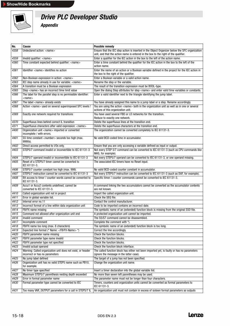
Drive PLC Developer StudioAppendix
15-18 lDDS EN 2.3
No. Possible remedyCause4358 Undeclared action: <name> Ensure that the IEC step action is inserted in the Object Organizer below the SFC organization
unit, and that the action name is entered in the box to the right of the qualifier.4359 Invalid qualifier: <name> Enter a qualifier for the IEC action in the box to the left of the action name.4360 Time constant expected behind qualifier: <name> Enter a time constant behind the qualifier for the IEC action in the box to the left of the
action name.4361 Identifier <name> identifies no action Enter the name of an action or a Boolean variable defined in the project for the IEC action in
the box to the right of the qualifier.4362 Non-Boolean expression in action: <name> Enter a Boolean variable or a valid action name.4363 IEC step name already in use for variable: <name> Rename the step or the variable.4364 A transition must be a Boolean expression The result of the transition expression must be BOOL-type.4365 Step <name> has an incorrect time limit value Open the dialog Step attributes for step <name> and enter valid time variables or constants.4366 The label for the parallel step is no permissible identifier:
<name>Enter a valid identifier next to the triangle identifying the jump label.
4367 The label <name> already exists You have already assigned this name to a jump label or a step. Rename accordingly.4368 Action <name> used on several superimposed SFC levels ! You are using the action <name> both in the organization unit as well as in one or several
actions of this organization unit.4369 Exactly one network required for transitions You have used several FBD or LD networks for the transition.
Reduce to exactly one network.4370 Superfluous lines behind correct IL transition Delete the superfluous lines at the transition end.4371 Superfluous characters after valid expression: <name> Delete the superfluous characters at the transition end.4400 Organization unit <name> imported or converted
incomplete / with errors.The organization cannot be converted completely to IEC 61131-3.
4401 S5 time constant <number> seconds too high (max.9990s).
No valid BCD-coded time in accumulator.
4402 Direct access permitted to I/Os only. Ensure that you are only accessing a variable defined as input or output.4403 STEP5/7 command invalid or inconvertible to IEC 61131-3 Not every STEP 5/7 command can be converted to IEC 61131-3 (such as CPU commands like
MAS, for example).4404 STEP5/7 operand invalid or inconvertible to IEC 61131-3 Not every STEP5/7 operand can be converted to IEC 61131-3, or one operand missing.4405 Reset of a STEP5/7 timer cannot be converted to
IEC 61131-3.The associated IEC timers have no Reset input.
4406 STEP5/7 counter constant too high (max. 999). No valid BCD-coded counter constant in accumulator.4407 STEP5/7 instruction cannot be converted to IEC 61131-3 Not every STEP5/7 instruction can be converted to IEC 61131-3 (such as DUF, for example).4408 Bit access to timer / counter words cannot be converted to
IEC 61131-3.Specific timer / counter commands cannot be converted to IEC 61131-3.
4409 Accu1 or Accu2 contents undefined, cannot beconverted to IEC 61131-3.
A command linking the two accumulators cannot be converted as the accumulator contentsare not known.
4410 Called organization unit not in project Import the called organization unit.4411 Error in global variable list. Check the SEQ file.4412 Internal error no.11 Contact the control manufacturer.4413 Incorrect format of a line within data organization unit Code to be imported contains an incorrect date.4414 FB/FX name missing The symbolic name of an (extended) function block is missing from the original S5D file.4415 Command not allowed after organization unit end A protected organization unit cannot be imported.4416 Invalid command The S5/S7 command cannot be disassembled.4417 Incomplete comment Complete the comment with *).4418 FB/FX name too long (max. 8 characters) The symbolic name of an (extended) function block is too long.4419 Expected line format (* Name: <FB/FX-Name> *) Correct the line accordingly.4420 FB/FX parameter name missing Check the function blocks.4421 FB/FX parameter type name invalid Check the function blocks.4422 FB/FX parameter type not specified Check the function blocks.4423 Invalid actual operand Check the function block interface.4424 Warning: Called organization unit does not exist, or header
incorrect or has no parametersThe called function block has either not been imported yet, is faulty or has no parameters(ignore the message in the latter case).
4425 No jump label defined The target of a jump has not been specified.4426 Organization unit has no valid STEP5 name such as PB10,
for example.Change the organization unit name.
4427 No timer type specified Insert a timer declaration into the global variable list.4428 Maximum STEP5/7 parenthesis nesting depth exceeded No more than seven left parentheses may be used.4429 Error in formal parameter name The parameter name must not be longer than four characters.4430 Formal parameter type cannot be converted to IEC Timers, counters and organization units cannot be converted as formal parameters to
IEC 61131-3.4431 Too many VAR_OUTPUT parameters for a call in STEP5/7 IL An organization unit must not contain in excess of sixteen formal parameters as outputs

Drive PLC Developer StudioAppendix
15-19l DDS EN 2.3
No. Possible remedyCause4432 Jump labels in the middle of an expression are not allowed IEC 61131-3 specifies exact jump label positions.4434 Too many labels An organization unit must not contain in excess of 100 labels.4435 No further connection after jump / call A jump or call must be followed by a load command.4436 VKE contents undefined, cannot be converted to
IEC 61131-3.A command using VKE cannot be converted as the VKE value is not known.
4437 The types of command and operand do not match A bit command was applied to a Word operand, or viceversa.4438 No data organization unit open (insert an A DB) Insert an A DB.4500 Unknown variable or address This Watch variable is not declared in the project. Use the Help Manager <F2> for declared
variables.4501 A valid Watch expression is followed by invalid characters. Remove the invalid characters.4520 Error in compiler directive: Flag expected before <name>! Pragma entered incorrectly. Check whether <name> is a valid flag.4521 Error in compiler directive:
Unexpected element <name>!Check the pragma for correct composition.
4522 Flag off directive expected ! There is no flag off instruction.Add a flag off instruction.4550 Index outside permitted range: Variable OD <number>, line
<line number>.Ensure that the index is within the range defined in dialog box Automation system settingstab Network functions.
4551 Subindex outside permitted range: Variable OD <number>,line <line number>.
Ensure that the subindex is within the range defined in dialog box Automation systemsettings tab Network functions.
4552 Index outside permitted range: Parameter OD <number>,line <line number>.
Ensure that the index is within the range defined in dialog box Automation system settingstab Network functions.
4553 Subindex outside permitted range: Parameter OD<number>, line <line number>.
Ensure that the subindex is within the range defined in dialog box Automation systemsettings tab Network functions.
4554 Invalid variable name: Variable OD <number>, line <linenumber>.
Enter a valid project variable in the field Variable. Use the notation <organization unitname>.<variable name> or, for global variables, <variable name>
4555 Table cell empty, input mandatory:Parameter OD %d, line %d
This field requires an input.
4556 Table cell empty, input mandatory: Variable OD %d, line %d This field requires an input.4800 The maximum number of tasks was exceeded. (Any touch
probe inputs also count as task).Delete a task, or remove a touch probe input.
4801 A hardware interrupt to start a task is used more thanonce.
Check all applied hardware interrupts.
4802 A task identifier is used more than once. Check all task identifiers.4803 A task priority has been assigned more than once.
Priority 0, Task not active, may be assigned more thanonce.
Check all assigned priorities.
4804 A digital input is used to start a task (hardware interrupt)and as touch-probe input. An input can be used either tostart a task or as TP, not both.
Either delete the TP input, or use a different input to start a task.
4805 Incorrect watchdog time.The watchdog time for a task is 0.
Check the task watchdog times.
4810 The codes stored in the Instance Parameter Managerrequire too much memory.
Delete some codes.
4811 Several initialization values were assigned to one code.Code initialization must be unique.
Check all initialization values.
4812 Error in the Parameter Manager. Refer message text for the cause.4813 A scale function was used in a global function block
instance.Instance function blocks with scale functions locally only.
4820 Error during code initialization value processing. The device description of the applied automation system was not found.4850 The applied version of the Drive PLC Developer Studio does
not allow the generation of an external library.Contact Lenze.

Drive PLC Developer StudioAppendix
15-20 lDDS EN 2.3
15.5.3 Communication errors
No. Cause Possible remedy1(0001)
Transmit buffer in the controller is full.CAN_ERR_XMTFULL
System-oriented communication error � 15-22
2(0002)
CAN controller was read too late.CAN_ERR_OVERRUN
4(0004)
Bus error: An error counter has reached the limit. Limit.CAN_ERR_BUSLIGHT
8(0008)
Bus error: An error counter has reached the limit.CAN_ERR_BUSHEAVY
16(0010)
Bus error: CAN controller assumed CANopen status bus off.CAN_ERR_BUSOFF
32(0020)
Rcv queue has been read out.CAN_ERR_QRCVEMPTY
64(0040)
Rcv queue was read out too late.CAN_ERR_QOVERRUN
128(0080)
Transmit queue is full.CAN_ERR_QXMTFULL
256(0100)
Register test of 82C200 failed.CAN_ERR_REGTEST
512(0200)
Problem with VxD localization.CAN_ERR_NOVXD
1024(0400)
Hardware occupied by the network.CAN_ERR_HWINUSE
2048(0800)
Network occupied by client.CAN_ERR_NETINUSE
5120(1400)
Hardware handle was invalid.CAN_ERR_ILLHW
6144(1800)
Network handle was invalid.CAN_ERR_ILLNET
7168(1C00)
Client handle was invalid.CAN_ERR_ILLCLIENT
8192(2000)
Resource (FIFO, client, timeout) cannot be generated.CAN_ERR_RESOURCE
40960(A000)
General error Contact Lenze
40961(A001)
This system bus adapter does not allow the selectedfunction.
Use a suitable system bus adapter.Contact Lenze.
40962(A002)
No system bus adapter active. Activate a system bus adapter.
41217(A101)
Internal program error (NULL pointer). Restart the application.If the error still occurs, contact Lenze.
41218(A102)
Bus device read timed out. Increase the value of parameter Communication timeout for the selected system bus adapteron the Settings tab.
41219(A103)
Internal program error (invalid network) Install the CAN driver update.If the error still occurs, contact Lenze.
41220(A104)
Internal program error (invalid data) Install the CAN driver update.If the error still occurs, contact Lenze.
41221(A105)
Internal program error (invalid operation) Install the CAN driver update.If the error still occurs, contact Lenze.
41222(A106)
Internal program errorError when reading a data block.
Restart the application.If the error still occurs, contact Lenze.
41223(A107)
Internal program error (invalid size) Restart the application.If the error still occurs, contact Lenze.
41224(A108)
Error when initializing the data download. Restart the application.Use the system bus configurator to check if the target system responds.
41225(A109)
Error when initializing the data upload. Restart the application.Use the system bus configurator to check if the target system responds.
41226(A10A)
Error during data transfer. Restart the application.Use the system bus configurator to check if the target system responds.
41227(A10B)
Incorrect I/O address Set a valid I/O address for the selected system bus adapter on the Settings tab.

Drive PLC Developer StudioAppendix
15-21l DDS EN 2.3
No. Possible remedyCause41228(A10C)
Incorrect interrupt Set a valid interrupt for the selected system bus adapter on the Settings tab.
41229(A10D)
Incorrect baud rate Set a valid baud rate for the selected system bus adapter on the Settings tab.
41230(A10E)
The drivers required for the selected system bus adapterwere not found.
Reinstall the drivers for the selected system bus adapter.
41231(A10F)
The system bus adapter is already used by anotherapplication in an incompatible mode.
Close all applications and try again.
41232(A110)
Error when loading the resources. Install the CAN driver update.If the error still occurs, contact Lenze.
41233(A111)
The configuration file could not be loaded. Reinstall the system bus default configuration.
41234(A112)
Automation system read error. Reset the automation system (mains switching) and try again.
41235(A113)
Error when reading from target system. Reset the target system (mains disconnection) and try again.
41236(A114)
The maximum number of supported communicationmodules (e. g., CAN USB adapters) was exceeded.
Remove one communication module.
41237(A115)
The installed drivers do not support the selected systembus adapter.
Install a driver update for the selected system bus adapter.
41238(A116)
A system bus adapter unknown to the system has beenselected.
Install a driver update for the system bus adapter to be used.
41239(A117)
System bus adapter initialization error. Check that the selected system bus adapter is connected properly to the PC.
41240(A118)
Error when writing the configuration file. Reinstall the CAN driver.
41241(A119)
The format of the configuration file is invalid. Reinstall the CAN driver.
41242(A11A)
Several PC system bus adapters 2177 connected to the PCat the same time.
Connect only the PC system bus adapter 2177 to be configured to the PC.
41243(A11B)
Error during USB device number write to PC system busadapter 2177.
Check that the system bus adapter is the only PC system bus adapter 2177 and properlyconnected to the PC.
41244(A11C)
Error during USB device number read from PC system busadapter 2177.
Check that the system bus adapter is the only PC system bus adapter 2177 and properlyconnected to the PC.
41245(A11D)
The file LSystembusL1.DLL could not be loaded. Reinstall the CAN driver.
41246(A11E)
he file LSystembusL1.DLL could not be loaded. Install the CAN driver update.If the error still occurs, contact Lenze
41247(A11F)
The system bus adapter could not be initialized.No free handles available..
Install the CAN driver update.If the error still occurs, contact Lenze
41248(A120)
The baud rate set for the selected system bus adapter doesnot match the baud rate of the devices connected to thebus.
Set the baud rate set for the bus devices for the selected system bus adapter on theSettings tab.
41249(A121)
The baud rate set for the selected system bus adapter doesnot match the baud rate of the devices connected to thebus.
Set the baud rate set for the bus devices for the selected system bus adapter on theSettings tab.
41250(A122)
Internal program errorInvalid filter setting.
Install the CAN driver update.If the error still occurs, contact Lenze.
41251(A123)
The parameter channel to be used is already used byanother bus station or by another PC program.
Set another parameter channel for the selected system bus adapter in the Settings index ofthe system bus configurator or ensure that the selected parameter channel is not occupiedby another bus station or another PC program.
41252(A124)
The LSystembusL2.DLL file could not be loaded. Reinstall the CAN driver update.
41253(A125)
Error when starting the download mode. Restart the application.
41254(A126)
Error during program download. Restart the application.
41255(A127)
- -
41256(A128)
Too many invalid telegrams have been detected on thesystem bus.
Check the installation of the system bus (terminating resistor, shielding) for the baud ratesused.
41728(A300)
Internal program errorOPC item could not be created.
Restart the application.
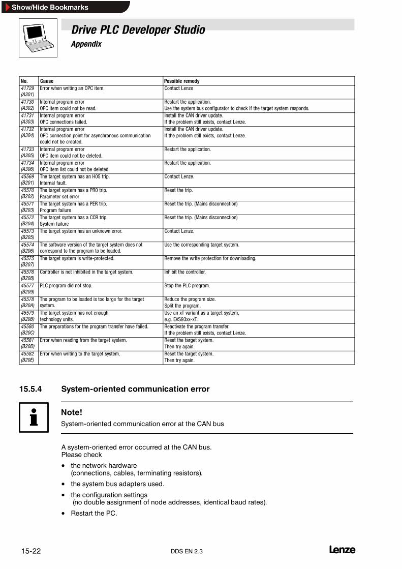
Drive PLC Developer StudioAppendix
15-22 lDDS EN 2.3
No. Possible remedyCause41729(A301)
Error when writing an OPC item. Contact Lenze
41730(A302)
Internal program errorOPC item could not be read.
Restart the application.Use the system bus configurator to check if the target system responds.
41731(A303)
Internal program errorOPC connections failed.
Install the CAN driver update.If the problem still exists, contact Lenze.
41732(A304)
Internal program errorOPC connection point for asynchronous communicationcould not be created.
Install the CAN driver update.If the problem still exists, contact Lenze.
41733(A305)
Internal program errorOPC item could not be deleted.
Restart the application.
41734(A306)
Internal program errorOPC item list could not be deleted.
Restart the application.
45569(B201)
The target system has an H05 trip.Internal fault.
Contact Lenze.
45570(B202)
The target system has a PR0 trip.Parameter set error
Reset the trip.
45571(B203)
The target system has a PER trip.Program failure
Reset the trip. (Mains disconnection)
45572(B204)
The target system has a CCR trip.System failure
Reset the trip. (Mains disconnection)
45573(B205)
The target system has an unknown error. Contact Lenze.
45574(B206)
The software version of the target system does notcorrespond to the program to be loaded.
Use the corresponding target system.
45575(B207)
The target system is write-protected. Remove the write protection for downloading.
45576(B208)
Controller is not inhibited in the target system. Inhibit the controller.
45577(B209)
PLC program did not stop. Stop the PLC program.
45578(B20A)
The program to be loaded is too large for the targetsystem.
Reduce the program size.Split the program.
45579(B20B)
The target system has not enoughtechnology units.
Use an xT variant as a target system,e.g. EVS93xx-xT.
45580(B20C)
The preparations for the program transfer have failed. Reactivate the program transfer.If the problem still exists, contact Lenze.
45581(B20D)
Error when reading from the target system. Reset the target system.Then try again.
45582(B20E)
Error when writing to the target system. Reset the target system.Then try again.
15.5.4 System-oriented communication error
Note!System-oriented communication error at the CAN bus
A system-oriented error occurred at the CAN bus.Please check
• the network hardware(connections, cables, terminating resistors).
• the system bus adapters used.
• the configuration settings(no double assignment of node addresses, identical baud rates).
• Restart the PC.

Drive PLC Developer StudioAppendix
15-23l DDS EN 2.3
15.6 Glossary
Sequential Function Chart Sequential Function Chart SFC (Sequential Function Chart - SFC) is a programming language to describesequential and parallel control processes with time and event control.
Action Boolean variable or instructions which can be controlled through an action block (in SFC).
Action block Activation description of actions in SFC.
Current event Intermediate result in IL of any data type.
Instruction List Instruction List (Instruction List - IL) is a common programming language for PLC systems similar toAssembler.
SFC Abbreviation for Sequential Function Chart
IL Abbreviation for Instruction List
Organization unit (Sub-)program unit which is part of a PLC program. Often organization units can be loaded into the PLCindependently of each other. Compare POU.
CPU Central processing unit (Central Processing Unit) of, e.g., a PLC.
Declaration Indication of variables and FB instances in a declaration block by also indicating the identifier, data typeand FB type as well as initial values, ranges and field features.
Declaration block Summary of declarations for a variable type at the beginning of a POU.
Elementary data type A standard data type predefined by IEC 61131-3.
Function extensions A function can have a variable number of inputs.
FB Abbreviation for Function Block (Function Block), often, function blocks are also called ”Functionorganization units”.
FB instance See Instance
FB type Name of a function block with request interface.
FBD Function Block Diagram, see Function Block Diagram
Function A POU of type Function
Function organization unit See Function block
Function block A POU of type Function_Block
Function Block Diagram The Function Block Diagram (Function Block Diagram) consists of a list of networks which enable theuser to create graphics that show any program process by means of connection elements.
FBD See Function Block Diagram
IL Instruction List, see Instruction List
Indirect FB call Call of an FB instance whose name has been transferred to a POU as VAR_IN_OUT parameter.
Instance Structured data set of an FB by declaration of a function block plus indication of the FB type.
LD Abbreviation for Ladder Diagram
Configuration The configuration (Configuration) defines the PLC structure and represents the highest level in theIEC 61131-3 software model.
Ladder Diagram Ladder Diagram (Ladder Diagram - LD) is a programming language to describe networks withsimultaneously operating Boolean and electromechanical elements such as contacts and coils.
LD Ladder Diagram, see Ladder Diagram
POU Abbreviation for Program Organization Unit (Program Organization Unit - POU)
POU Program Organization Unit, see Program Organization Unit
Program Organization Unit The Program Organization Unit is an organization unit in IEC 61131-3 of type function, function block orprogram. It builds up user programs hierarchically.
Resource A resource (Resource) is a central unit (CPU) of a configuration.
Step Status node in an SFC program. Actions referring to a step are started here.
SFC Sequential Function Chart, see Sequential Function Chart
PLC Programmable Logic Controller (Programmable Controller).

Drive PLC Developer StudioAppendix
15-24 lDDS EN 2.3
ST Abbreviation for Structured Text.
Standard functions All functions predefined by IEC 61131-3 to implement PLC typical functionality.
Standard organization units See Standard function blocks
Standard function blocks All function blocks (Function Blocks) predefined by IEC 61131-3 to implement PLC typical functionality.
Structured Text Structured Text (Structured Text) is a programming language to describe algorithms and execution controlby means of the latest high languages.
Task Definition of run time features of a program.
Transition Transition from one SFC step to the next by evaluation of the transition condition.
Type definition Definition of a user-specific data type based on already existing data types.
Variable Name of a data memory which can contain values determined by the data type or variable declaration.
Cycle The cycle of a (periodically called) user program.
Cycle time The cycle time is the time needed by the user progam for a cycle.

Drive PLC Developer StudioIndex
16-1l DDS EN 2.3
16 Index
AAbsolute value, 14-5
Access rights, 5-15, 6-21, 6-28
Add action, 7-63
Add entry action, 7-58
Add exit action, 7-59
Add label to parallel branch, 7-59
Add program call, 8-34
Add subelement, 8-24
Add task, 8-33
Addition, 12-1
Addressing function, 12-12
Administrator rights, 6-21
Align, 9-8
Alternative branch (left), 7-57
Alternative branch (right), 7-57
Angle, 9-13
Anisotropic, 9-18
Arc cosine, 14-6
Arc sine, 14-6
Arc tangent, 14-7
Archive, 6-3
Arrange icons, 5-5
Arrange in accordance with the data flow, 7-52
Arrange topologically, 7-51
Ask for project information, 5-7
Assignment, 7-30
Assignment operator, 4-5, 12-13
Associate action, 7-62
Auto declaration , 5-8
Autoformat, 5-8
Autoload, 5-7
Autosave, 5-6
Autosave interval, 5-6
BBasic language, 5-18
Basic parameters, 8-26
Binary file, 5-13
Binary selection, 12-8
Bistable function blocks, 14-10
Bit channels, 8-27
Bit values, 5-9
Bitmap, 9-4, 9-18
Box input, 7-45
Breakpoint, 2-9
Breakpoint dialog, 6-35
Breakpoint on/off, 6-34
Breakpoint, 7-28, 7-65
Bring forward by one, 7-52
Build, 5-13
Button, 9-4
CCalculate addresses , 8-25
Call hierarchy, 6-37
Calling a function block, 2-5
Calling up a function block, 12-12
Cascade, 5-5
CFC, 4-19
Change colour, 9-13
Changing values online, 2-10
Channel parameters, 8-27
CheckBounds, 2-3
CheckDiv, 12-2
CheckRange, 10-8
Clean all, 6-9
Close, 6-2
Close all, 5-5
Code list, 8-7
Codes, 8-8
Coil, 7-37
Colours, 5-10, 9-12
Comment, 7-45
Comments, 5-13
Communication driver, 6-38
Communication parameters, 6-37, 6-38
Compare, 6-15
Compile, 6-8

Drive PLC Developer StudioIndex
16-2 lDDS EN 2.3
Compile all, 6-8
Compiler error messages, 15-11
Concatenation, 14-8
Configure, 9-11
Configuring the monitoring window, 7-24
Connector, 7-48
Constants, 5-13, 7-11
Contact, 7-37
Continuous function chart editor, 4-19
Controller enable, 6-41
Controller inhibit, 6-41
Convert object, 6-27
Convert PLC configurations, 8-25
Copy, 6-17, 7-2, 7-34
Copy object, 6-27
Copying with the Ctrl key, 9-7
Cosine, 14-6
Create backup, 5-6
Create document template, 8-3
Create new project, 3-2
Create organization units, 3-2
Create translation file, 6-12
Creating a channel to the gateway PC, 6-40
Curve, 9-3
Cut, 7-2, 7-34
Cyclical task, 8-29
DData consistency, 8-30
Data types, 2-8
Debugging, 2-1, 2-9, 5-13
Declaration keywords, 7-11
Declarations as tables, 5-8, 7-10, 7-18
Default configuration, 8-25
DEFAULT.DFR, 6-6
Definitions, 1-1
Delete, 7-3, 7-34
Delete action/transition, 7-60
Delete background bitmap, 9-11
Delete object, 6-26
Deleting a breakpoint, 6-35
Desktop, 5-9
Directories, 5-11
Display, 7-51
Display at step, 7-62
Display project log , 6-43
Division, 12-1
Document project, 6-13
Documentation setup, 6-6
Down counter, 14-14
Download information, 6-9
Drag & Drop, 6-25
EEdit object, 6-27
Editing time limits, 7-61
Editor, 5-7
Element list, 9-8
Element number, 9-5
Ellipse, 9-3
EN/ENO, 7-46
Equal to, 12-11
Evaluating expressions, 4-4
EVENT, 8-29
Event-controlled task, 8-29
Exception handling, 6-22
Exclude, 6-11
Execute program, 9-17
Exit, 6-8
Expand macro, 7-54
Expand node, 6-25
Exponential function, 14-5
Exponentiation, 14-7
Export, 6-14
Expressions, 4-4
FFalling edge detector, 14-13
File, 6-1
Find, 7-4
Find next, 7-4
Font, 5-8
Form, 9-11
Frame, 9-10
Function, 2-2, 7-22
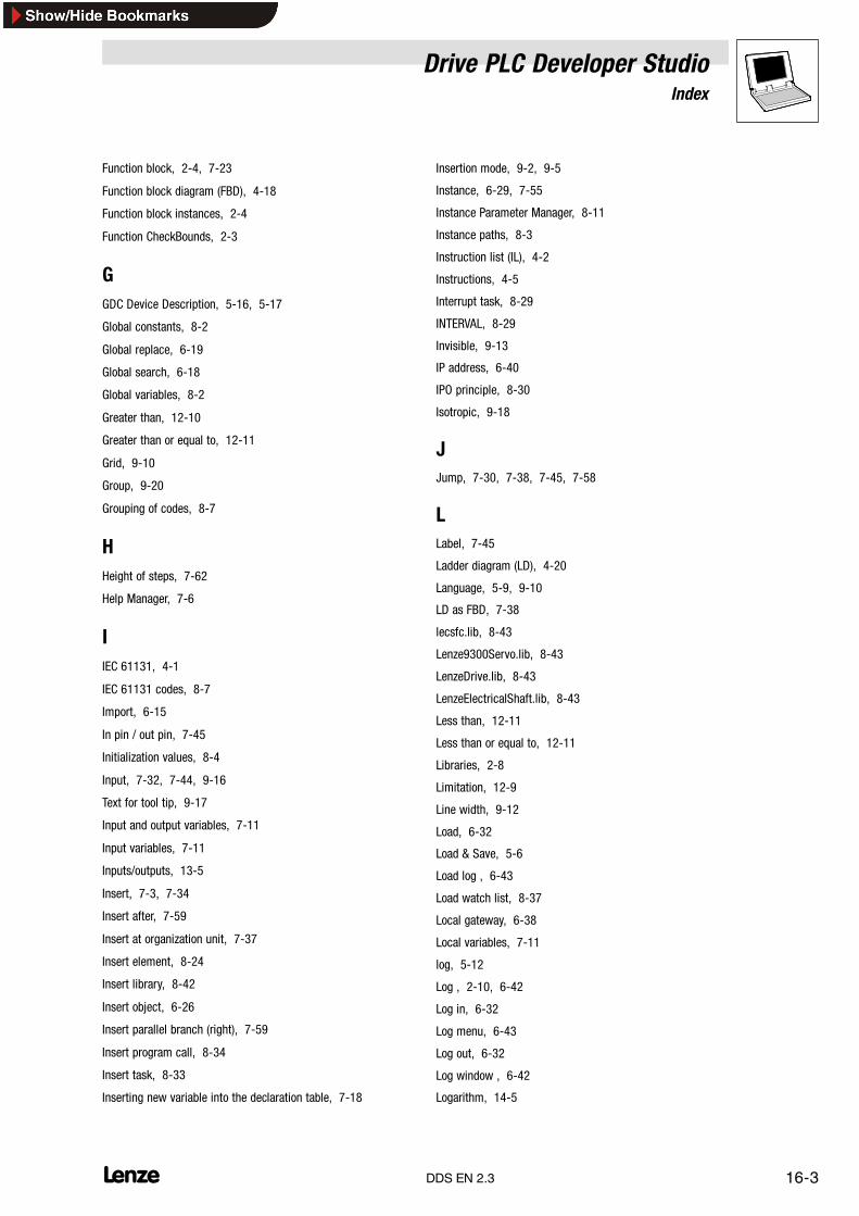
Drive PLC Developer StudioIndex
16-3l DDS EN 2.3
Function block, 2-4, 7-23
Function block diagram (FBD), 4-18
Function block instances, 2-4
Function CheckBounds, 2-3
GGDC Device Description, 5-16, 5-17
Global constants, 8-2
Global replace, 6-19
Global search, 6-18
Global variables, 8-2
Greater than, 12-10
Greater than or equal to, 12-11
Grid, 9-10
Group, 9-20
Grouping of codes, 8-7
HHeight of steps, 7-62
Help Manager, 7-6
IIEC 61131, 4-1
IEC 61131 codes, 8-7
Import, 6-15
In pin / out pin, 7-45
Initialization values, 8-4
Input, 7-32, 7-44, 9-16
Text for tool tip, 9-17
Input and output variables, 7-11
Input variables, 7-11
Inputs/outputs, 13-5
Insert, 7-3, 7-34
Insert after, 7-59
Insert at organization unit, 7-37
Insert element, 8-24
Insert library, 8-42
Insert object, 6-26
Insert parallel branch (right), 7-59
Insert program call, 8-34
Insert task, 8-33
Inserting new variable into the declaration table, 7-18
Insertion mode, 9-2, 9-5
Instance, 6-29, 7-55
Instance Parameter Manager, 8-11
Instance paths, 8-3
Instruction list (IL), 4-2
Instructions, 4-5
Interrupt task, 8-29
INTERVAL, 8-29
Invisible, 9-13
IP address, 6-40
IPO principle, 8-30
Isotropic, 9-18
JJump, 7-30, 7-38, 7-45, 7-58
LLabel, 7-45
Ladder diagram (LD), 4-20
Language, 5-9, 9-10
LD as FBD, 7-38
lecsfc.lib, 8-43
Lenze9300Servo.lib, 8-43
LenzeDrive.lib, 8-43
LenzeElectricalShaft.lib, 8-43
Less than, 12-11
Less than or equal to, 12-11
Libraries, 2-8
Limitation, 12-9
Line width, 9-12
Load, 6-32
Load & Save, 5-6
Load log , 6-43
Load watch list, 8-37
Local gateway, 6-38
Local variables, 7-11
log, 5-12
Log , 2-10, 6-42
Log in, 6-32
Log menu, 6-43
Log out, 6-32
Log window , 6-42
Logarithm, 14-5

Drive PLC Developer StudioIndex
16-4 lDDS EN 2.3
MMacro, 7-9
Macro, 7-53
Mark, 5-8
Mark all, 7-46
Maximum comment size, 7-26
Maximum function, 12-8
Memory/Address Manager, 13-6
Messages, 5-5
Minimize node, 6-25
Minimum comment size, 7-26
Minimum function, 12-9
Modifiers, 4-2, 11-1
Module number, 13-5
Modulo division, 12-3
Monitoring, 2-10, 3-14, 7-28, 7-65
Monitoring active, 8-37
Motion absolute, 9-12
Motion relative, 9-13
Multi-element variables, 7-19
Multiplexer, 12-10
Multiplication, 12-1
NNegation, 4-20, 7-33, 7-39, 7-46
Network (after), 7-26
Network (before), 7-26
New, 6-1
New folder, 6-25
New watch list, 8-36
New, with template, 6-1
Next fault, 7-8
Normal data processing, 8-30
Not equal to, 12-11
OObject Organizer, 8-1
Online in security mode, 5-9
Online mode, 5-4
Open, 6-2
Open instance, 7-34, 7-40
Operand, 7-22
Operator, 7-22, 7-31, 7-39, 7-44
Operators, 4-2, 11-1
Options, 7-62
Options for network comments, 7-26
Organization unit, 2-2
Output, 7-33, 7-44
Output call tree, 6-29
Output cross reference list, 6-30
Output unused variables, 6-31
Output variables, 7-11
PParallel branch (left), 7-58
Parallel branch (right), 7-58
Parallel contact, 7-37
Parallel or series connection, 4-20
Parameter Manager, 8-8Terminology, 8-10
Parameter monitor, 8-6
Parameterizing codes, 8-7
Passwords, 5-14
Paste above, 7-39
Paste after, 7-39
Paste below, 7-39
Placeholder, 6-7
Placeholder concept , 9-19
Placeholders, 9-9
PLC configuration in online mode, 8-24
PLC_PRG, 2-7, 8-29
Polygon, 9-4
Polyline, 9-3
Position information, 6-11
Pragma, 7-20
Previous fault, 7-8
Print, 6-6
Printer borders, 5-10
PRIORITY, 8-30
Process image, 8-20, 8-21
Program, 2-6
Program example, 2-6
Program tutorial, 3-1
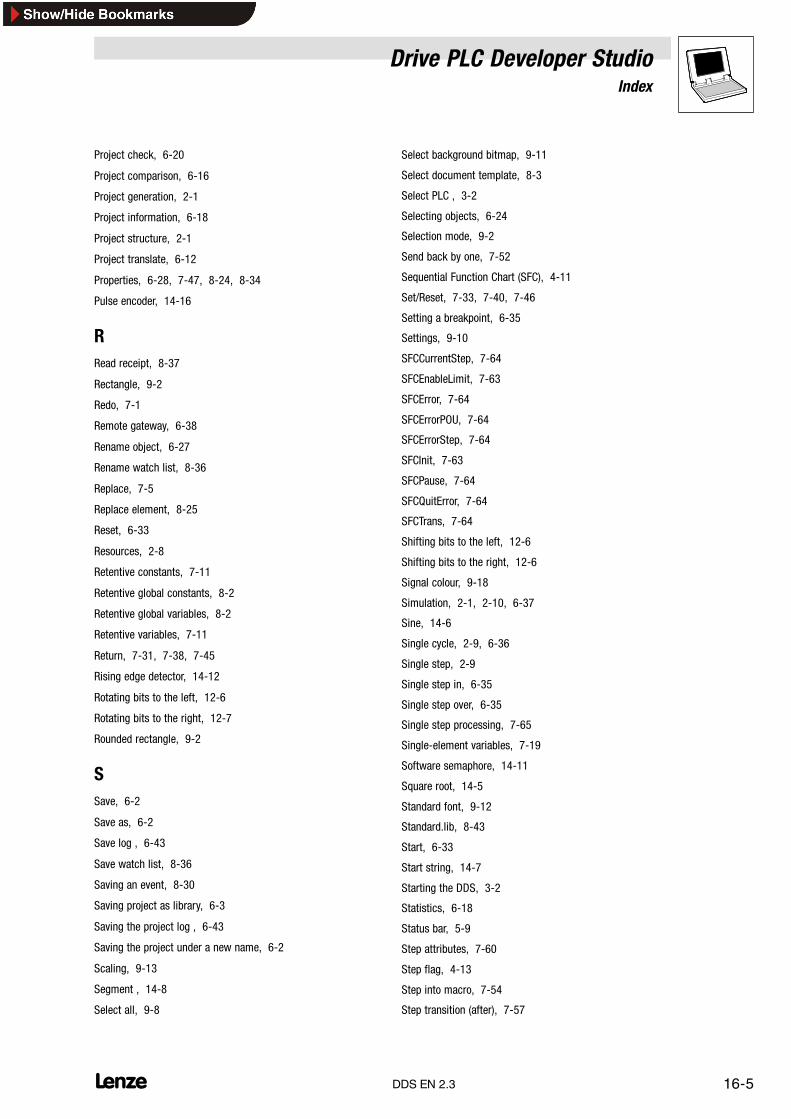
Drive PLC Developer StudioIndex
16-5l DDS EN 2.3
Project check, 6-20
Project comparison, 6-16
Project generation, 2-1
Project information, 6-18
Project structure, 2-1
Project translate, 6-12
Properties, 6-28, 7-47, 8-24, 8-34
Pulse encoder, 14-16
RRead receipt, 8-37
Rectangle, 9-2
Redo, 7-1
Remote gateway, 6-38
Rename object, 6-27
Rename watch list, 8-36
Replace, 7-5
Replace element, 8-25
Reset, 6-33
Resources, 2-8
Retentive constants, 7-11
Retentive global constants, 8-2
Retentive global variables, 8-2
Retentive variables, 7-11
Return, 7-31, 7-38, 7-45
Rising edge detector, 14-12
Rotating bits to the left, 12-6
Rotating bits to the right, 12-7
Rounded rectangle, 9-2
SSave, 6-2
Save as, 6-2
Save log , 6-43
Save watch list, 8-36
Saving an event, 8-30
Saving project as library, 6-3
Saving the project log , 6-43
Saving the project under a new name, 6-2
Scaling, 9-13
Segment , 14-8
Select all, 9-8
Select background bitmap, 9-11
Select document template, 8-3
Select PLC , 3-2
Selecting objects, 6-24
Selection mode, 9-2
Send back by one, 7-52
Sequential Function Chart (SFC), 4-11
Set/Reset, 7-33, 7-40, 7-46
Setting a breakpoint, 6-35
Settings, 9-10
SFCCurrentStep, 7-64
SFCEnableLimit, 7-63
SFCError, 7-64
SFCErrorPOU, 7-64
SFCErrorStep, 7-64
SFCInit, 7-63
SFCPause, 7-64
SFCQuitError, 7-64
SFCTrans, 7-64
Shifting bits to the left, 12-6
Shifting bits to the right, 12-6
Signal colour, 9-18
Simulation, 2-1, 2-10, 6-37
Sine, 14-6
Single cycle, 2-9, 6-36
Single step, 2-9
Single step in, 6-35
Single step over, 6-35
Single step processing, 7-65
Single-element variables, 7-19
Software semaphore, 14-11
Square root, 14-5
Standard font, 9-12
Standard.lib, 8-43
Start, 6-33
Start string, 14-7
Starting the DDS, 3-2
Statistics, 6-18
Status bar, 5-9
Step attributes, 7-60
Step flag, 4-13
Step into macro, 7-54
Step transition (after), 7-57

Drive PLC Developer StudioIndex
16-6 lDDS EN 2.3
Step transition (before), 7-57
Stop, 6-33
String length, 14-7
Structured text (ST), 4-4
Subcodes, 8-16
Subtraction, 12-1
System codes, 8-7
System error, 8-31
System organization units, 8-23
System POU, 2-7
TTab, 8-1
Tabs, 5-2
Tab width, 5-8
Tangent, 14-6
Target languages, 6-11
Task monitor, 8-28
Task overflow, 8-31
Task types, 8-29
TasksCyclical task, 8-28, 8-29
Event-controlled task, 8-29
Interrupt task, 8-29
PLC_PRG, 8-29
System task, 8-28
Time-controlled task, 8-29
TCP/IP network, 6-40
Text, 9-11
Text display, 9-13
Tile horizontally, 5-5
Tile vertically, 5-5
Time flag, 4-13
Time limit overview, 7-61
Time-controlled task, 8-29
Timer off-delay, 14-18
Timer on-delay, 14-17
Tip variable, 9-16
To the background, 9-8
To the beginning, 7-53
To the end, 7-53
To the foreground, 9-8
Toggle variable, 9-16
Tool bar, 5-9
Tool tip, 5-2, 7-19
Transition jump, 7-58
Translate, 6-9
Translate project into another language, 6-12
Translation file, 6-11, 6-12
Types for variable declaration, 7-15
UUndo, 7-1
Up and down counter, 14-15
Up counter , 14-14
Use IEC steps, 7-62
User codes, 8-7
User group passwords, 6-21
User groups, 6-21
User information, 5-7
VVariables, 9-13
View, 9-10
Visualization, 2-8, 9-1, 9-4
WWarnings, 5-10
Watchdog time, 8-31
Width of steps, 7-62
Write receipt, 8-37
Write values, 6-36
Writing values in FBD, 7-28
XX /Y position, 9-5
X offset/Y offset, 9-12
ZZoom, 7-34, 7-55
Zoom action/transition, 7-60
Zoom to Vis, 9-17


