52
Thursday, May 25, 2006 GNU Tools Manual Issue: 1.26 Date:May 25, 2006 GettingStartedManual.odt 1

Thursday, May 25, 2006
GNU Tools Manual
Issue: 1.26Date:May 25, 2006
GettingStartedManual.odt1

Thursday, May 25, 2006
Contents1. Installing the tools
1.1. Windows installation1.2. Linux installation
2. Tools operation2.1 RedBoot getting started the “simple steps”.2.2 Ethernet Ping from a host to the Viper2.3 Ethernet Ping from Viper to host2.4 Running GDB with the test programs using the serial port2.5 Running GDB with the test programs using the Ethernet port2.6 Running the example hello2.7 Programming the helloviper program into flash reboot prompt loading2.8 Programming the Viper to Boot to.2.9 ReBuilding and Reinstalling RedBoot
3. Setting up the Viper/860 to run Linux3.1 Building and testing code on the Viper
4. Linux and the Adder MPC8xx
5. Linux and the Rattler MPC82xx
6. ptx file system
7. Linux Commands
8. Redboot commands
9. Altering the FPGA
Appendices
Appendix A: ReferencesAppendix B: Example programsAppendix C: Web Links, Discussion groups etc.Appendix D: Linux configuration information dhcpd.conf etcAppendix E: Programming Redboot to a blank FlashAppendix F: Modifying the default boot bash_profile under linuxAppendix G: Further notes on Linux compiling.Appendix H: eCos and the MPC866T on the Viper II (current viper board in production)Appendix I: Booting a board with Linux NFS from your host Linux PC
GettingStartedManual.odt2

Thursday, May 25, 2006Appendix J: Static IP Addressing using Windows and a cross over cableAppendix K: Checking for Board types in the ecos.db file
Appendix X: Contacting Analogue & Micro Ltd
GettingStartedManual.odt3

Thursday, May 25, 2006
1. Installing the tools
Items supplied:-PSU note this can be an optionBoardSerial CableDocumentaion CD ROMLinux Tools CD ROM Windows eCosTools CD ROM
Firstly locate the CD ROM disk eCostools and the Documentation CD ROM then please follow the following simple steps.
i. Decide what embedded operating system you will use eCos or Linux or both.ii. PLEASE REMEMBER THAT the embedded Linux tools only operate under
Linux NOT WINDOWS.
iii. If you are to use eCos under windows install using the setup.exe program from the eCostools CD ROM and follow the setup instructions to create a cygwin install.
iv. If you are a serious user or would like to try out both systems then it is recommended that you install all the tools into a PC running RH9 Linux or Fedora Core (please see notes to install into RH9 Linux ). Installation is via rpm files installed from the directory eCos_Linux_<BoardGroup>/RPM and amltd_tools/RPM directorys on the documentation CD ROM.
1.1. Windows installation
i. If you have a previous installation delete the registry entry Cygnus Solutions under HKEY_LOCAL_MACHINE >SOFTWARE
ii. Then place the CD in the drive and run Setup.exe from the CD drive. The following dialog appears
GettingStartedManual.odt4

Thursday, May 25, 2006
press next
Now leave the install from local directory as this will install from your CDROM as you have started setup from this location. Press Next
GettingStartedManual.odt5

Thursday, May 25, 2006
We suggest you leave the default directory to C:\cygwin. Press next
This should be the drive location of the CDROM. In this case drive D: is the CDROM containing the installation disk. Press next and checking all of the MD5 check sums starts - this may take a while. The following should then appear.
GettingStartedManual.odt6
Thursday, May 25, 2006
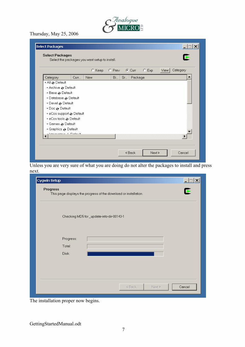
Unless you are very sure of what you are doing do not alter the packages to install and press next.
The installation proper now begins.
GettingStartedManual.odt7
Thursday, May 25, 2006
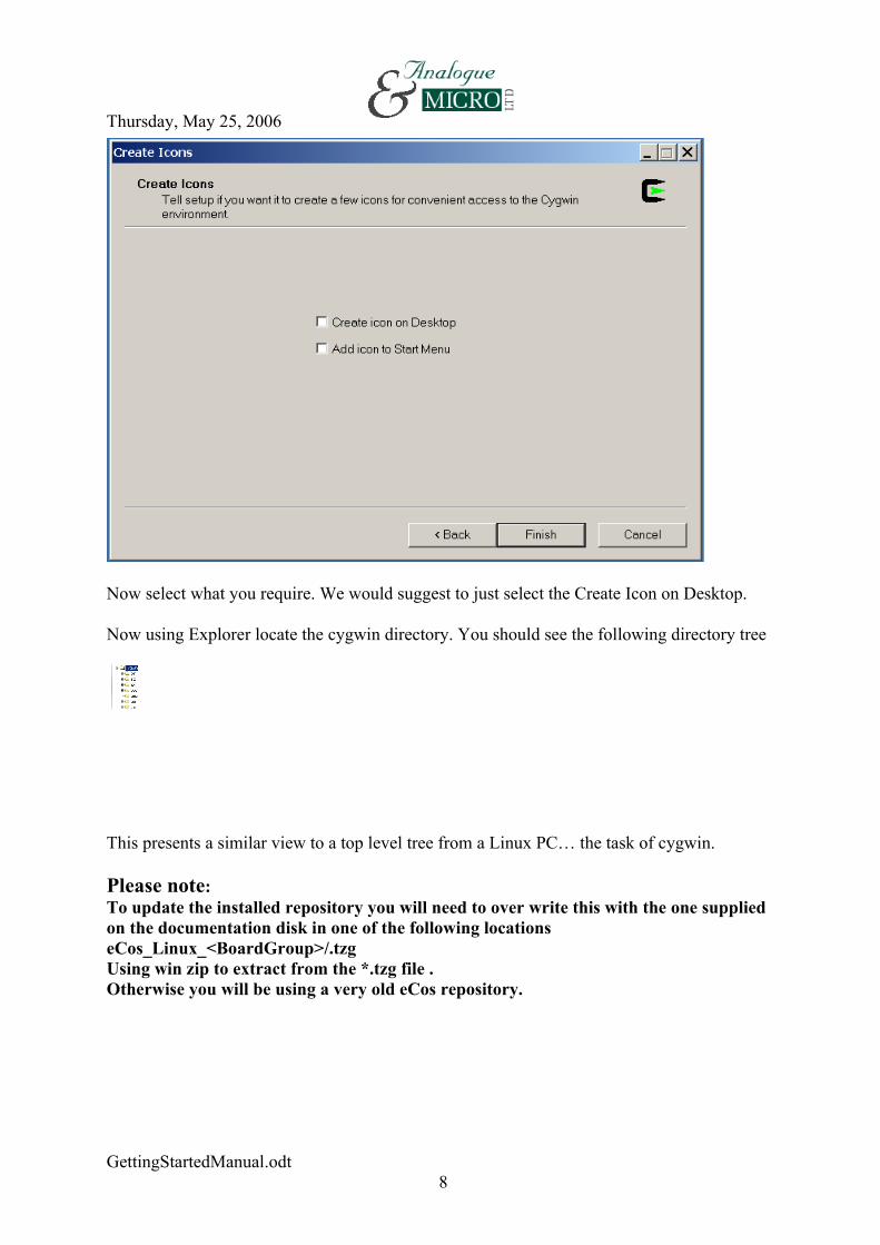
Now select what you require. We would suggest to just select the Create Icon on Desktop.
Now using Explorer locate the cygwin directory. You should see the following directory tree
This presents a similar view to a top level tree from a Linux PC… the task of cygwin.
Please note:To update the installed repository you will need to over write this with the one supplied on the documentation disk in one of the following locationseCos_Linux_<BoardGroup>/.tzgUsing win zip to extract from the *.tzg file .Otherwise you will be using a very old eCos repository.
GettingStartedManual.odt8

Thursday, May 25, 20061.2. Linux installation
Note:1. The Tool RPMS are on the Linux Tools CD ROM2. The OS RPMS (eCos and Linux) are on the documentation CD ROM
All tools and OS RPMS are installed under /opt/amltd directoryThe following steps are for RH9 to install the tools
# mount /mnt/cdromFor the OS installs# cd /mnt/cdrom/eCos_Linux_<boardtype>/RPMSTool installs# cd /mnt/cdrom/amltd_tools/RPMS/noarch# rpm –ivh *.rpm# cd /mnt/cdrom/amltd_tools/RPMS/RH9# rpm –ivh *.rpm
Now you also may need to add a soft link as a tcl link has changed libtcl.so.0 is missing
# ln -s /usr/lib/libtcl.so /usr/lib/libtcl.so.0
The following steps are for Fedora Core to install the tools
# mount /mnt/cdromFor the OS installs# cd /mnt/cdrom/eCos_Linux_<boardtype>/RPMSTool installs# cd /mnt/cdrom/amltd_tools/RPMS/noarch# rpm –ivh *.rpm# cd /mnt/cdrom/amltd_tools/RPMS/FC3# rpm –ivh *.rpm
Where for a rattler <boardtype>= rattler8250_8250pci_8280pci
ALSO READ THE README FILE ON THE CD FOR MORE COMPLETE UP TO DATE INFORMATION.
Finally for updating RPMS the following sequence is recommended.
Firstly remove all of the above rpms by first searching for them as follows
# rpm –qa | grep amltd_tools# rpm –qa | grep jffs# rpm –qa | grep ppc
Or for older versions of RPMS# rpm –qa | grep mlb_tools# rpm –qa | grep jffs# rpm –qa | grep ppc
GettingStartedManual.odt9

Thursday, May 25, 2006
Then removing the listed rpm names do this for all the rpms, ppc, jffs etc.
# rpm –e <rpm name>
You may also need to initialise the rpm database by the following commands
# rpm -–initdb# rpm --rebuilddb
For Fedora core installation follow the steps for RH9 also read the readme files on the CDROM for complete up to date information.
Finally read APPENDIX F to set the boot up defaults for the tool paths
Notes:3. Due to some dependency changes in RedHat it is necessary force some of the
packages with -–nodeps option some times.Tools operation
The following instructions are referenced to installations under both Windows and Linux. It is assumed at all times the commands entered via Windows are through the cygwin shell, which provides a mini Linux look alike structure to run Linux commands on Windows OS as can be seen from the structure created on the previous pages. So if Windows is being used make sure you are running the cygwin shell.In Linux all commands are entered via a xterm shell.
Please note in the following text the AdderII and the Viper platforms are referenced only. These commands in general also apply to other platforms produced by Analogue & Micro Ltd.
Note: Always use the SMC serial port for debugging not SCC check your board documentationBOARD TIMEOUT :
On initial turn on the board will carry out the following proceedure 1. The board boots up using the ROM version of redboot ( At this point you can
either press <Esc> into the terminal then type A&M: to recover to the minimal RedBoot., or wait for the time out as in 2 or press <space> to ignore the time out going straight to the ROMRAM Redboot).
2. It then times out and will run the ROMRAM version of redboot.3. In the event you do not want to run the ROMRAM version Type the following
via your serial terminal (e.g. minicom) <ESC>to give back >>then type
A&M:This then enters the ROM RedBoot
GettingStartedManual.odt10

Thursday, May 25, 2006or press <Space> not <Esc> to just enter the main reboot
2.1 RedBoot getting started the “simple steps”.
The Basics
You will now need the following itemsi. Null modem cable.ii. Ethernet hub connection or a switch-over cable.iii. Ethernet Patch cable to your Ethernet hub port.iv. TFTP server running on your network somewhere ?
If you do not intend to use Ethernet or TFTP file down load to the Viper you will not need items ii to iv.
i. Now connect :
a. A null modem cable between your PC and the viper board connecting SK7 Viper to COM1 PC.
b. The Ethernet cable between SK1 and the Hub connection port.(omit this if you do not which to use Ethernet). Do not directly connect this to the PC Ethernet card - it will need to be connected via a hub.
ii. Now start up your terminal program in Windows HyperTerminal or Minicom in Linux. The settings should be as follows a. Baud 38400 b. No Bits 8c. Parity Noned. Flow control None.
iii. Now switch on the board. The following response should happen in your terminal window.
+FLASH configuration checksum error or invalid keyEthernet eth0: MAC address 00:00:00:00:00:02IP: 192.168.1.42, Default server: 192.168.1.1
RedBoot(tm) bootstrap and debug environment [ROMRAM]
GettingStartedManual.odt11

Thursday, May 25, 2006Non-certified release, version 1.5.16fc - built 17:44:59, Apr 30 2002
Platform: A&M VIPER (PowerPC 860)Copyright (C) 2000, 2001, 2002, Red Hat, Inc.
RAM: 0x00000000-0x00800000, 0x0002fbb8-0x007e1000 availableFLASH: 0xfe000000 - 0xfe100000, 16 blocks of 0x00010000 bytes each.RedBoot>
Do not worry about the “checksum error or invalid key” at this point.
iv. The first item to do is to initialize the flash file system type
RedBoot> fis initAt the RedBoot prompt the Viper will then respond with
About to initialize [format] FLASH image system - are you sure (y/n)? yType ‘y’. It will then respond with
*** Initialize FLASH Image System Warning: device contents not erased, some blocks may not be usable... Erase from 0xfe0f0000-0xfe100000: .... Program from 0x007ef000-0x007ef300 at 0xfe0f0000: .RedBoot>
Then if you type
RedBoot> fis listThe Viper should then respond with
Name FLASH addr Mem addr Length Entry pointRedBoot 0xFE000000 0xFE000000 0x00030000 0x00000000RedBoot config 0xFE0E0000 0xFE0E0000 0x00001000 0x00000000FIS directory 0xFE0F0000 0xFE0F0000 0x00010000 0x00000000RedBoot>
v. To configure the Ethernet Mac addressIf you now type
RedBoot>fconfigThe Viper will respond with the followingRun script at boot: falseAccept - press carriage return
Use BOOTP for network configuration: trueAccept - press carriage returnDNS server IP address:Accept - press carriage returnNetwork hardware address [MAC]: 0x00:0x00:0x00:0x00:0x00:0x02Alter and then press carriage returnGDB connection port: 9000Accept - press carriage returnForce console for special debug messages: falseAccept - press carriage return
GettingStartedManual.odt12

Thursday, May 25, 2006
Network debug at boot time: falseAccept - press carriage returnUpdate RedBoot non-volatile configuration - are you sure (y/n)?yI you are happy type “y” then carriage return.
At this stage the board is basically configured with no applications running. You should now switch the board off for a few moments before continuing and then switch on to resume further operations.
+Ethernet eth0: MAC address 00:00:00:00:00:02IP: 192.168.1.42, Default server: 192.168.1.1
RedBoot(tm) bootstrap and debug environment [ROMRAM]Non-certified release, version 1.5.16fc - built 17:44:59, Apr 30 2002
Platform: A&M VIPER (PowerPC 860)Copyright (C) 2000, 2001, 2002, Red Hat, Inc.
RAM: 0x00000000-0x00800000, 0x0002fbb8-0x007e1000 availableFLASH: 0xfe000000 - 0xfe100000, 16 blocks of 0x00010000 bytes each.RedBoot>
The above is displayed showing an IP address of IP: 192.168.1.42
GettingStartedManual.odt13

Thursday, May 25, 2006
2.2 Ethernet Ping from a host to the Viper
The board should be switched on at the RedBoot promptRedBoot>
It can now be seen earlier that the Viper has been assigned an IP address of IP: 192.168.1.42
+Ethernet eth0: MAC address 00:00:00:00:00:02IP: 192.168.1.42, Default server: 192.168.1.1
So if you now type C:\>ping 192.168.1.42 from windowsOr # ping 192.168.1.42 from Linuxfrom your host PC command line the following response should be:Pinging 192.168.1.42 with 32 bytes of data:
Reply from 192.168.1.42: bytes=32 time<10ms TTL=64Reply from 192.168.1.42: bytes=32 time<10ms TTL=64Reply from 192.168.1.42: bytes=32 time<10ms TTL=64Reply from 192.168.1.42: bytes=32 time<10ms TTL=64
2.3 Ethernet Ping from Viper to host
You need to know the IP address you wish to Ping first, so we will use the host PC using Windows NT. Type
C:\>ipconfigIn a command window
Windows NT IP Configuration
Ethernet adapter PCINT8:
IP Address. . . . . . . . . : 192.168.1.19 Subnet Mask . . . . . . . . : 255.255.255.0 Default Gateway . . . . . . : 192.168.1.1
We now know the host IP address is IP Address. . . . . . . . . : 192.168.1.19
Or Using Linux[root@localhost root]# ifconfigeth0 Link encap:Ethernet HWaddr 00:30:F1:11:81:13 inet addr:10.0.0.1 Bcast:10.0.255.255 Mask:255.255.0.0 UP BROADCAST RUNNING MULTICAST MTU:1500 Metric:1 RX packets:0 errors:0 dropped:0 overruns:0 frame:0 TX packets:71 errors:0 dropped:0 overruns:0 carrier:0 collisions:0 txqueuelen:100 RX bytes:0 (0.0 b) TX bytes:12596 (12.3 Kb) Interrupt:11 Base address:0x4000
eth1 Link encap:Ethernet HWaddr 00:04:5A:90:9A:DE inet addr:192.168.12.245 Bcast:192.168.12.255 Mask:255.255.255.0 UP BROADCAST RUNNING MULTICAST MTU:1500 Metric:1 RX packets:2657 errors:0 dropped:0 overruns:0 frame:0 TX packets:1970 errors:0 dropped:0 overruns:0 carrier:0 collisions:0 txqueuelen:100 RX bytes:343510 (335.4 Kb) TX bytes:1191459 (1.1 Mb) Interrupt:3 Base address:0x300
GettingStartedManual.odt14

Thursday, May 25, 2006lo Link encap:Local Loopback inet addr:127.0.0.1 Mask:255.0.0.0 UP LOOPBACK RUNNING MTU:16436 Metric:1 RX packets:70 errors:0 dropped:0 overruns:0 frame:0 TX packets:70 errors:0 dropped:0 overruns:0 carrier:0 collisions:0 txqueuelen:0 RX bytes:4820 (4.7 Kb) TX bytes:4820 (4.7 Kb)
[root@localhost root]#
The board should be switched on at the RedBoot promptRedBoot>
Now typeRedBoot> ping -h 192.168.1.19
To ping the host machine you are using the response should be
Network PING - from 192.168.1.42 to 192.168.1.19PING - received 10 of 10 expectedRedBoot>
2.4 Running GDB with the test programs using the serial port
The board should be connected with at least the serial null modem cable connected between host PC and the Viper board.Note: Always use the SMC serial port for debugging not SCC check your board documentation
Important:- no terminal program should be running.
Using Windows NT the “Cygwin window ” should be running.Using Linux an xterm shell should be running
Now copy the file ‘helloviper’ or ‘helloadderII’ to your local directoryWindows/cygwin/home/yourloginname/helloviper Linux/home/yourloginname/helloviper
Then run the “powerpc-eabi-gdb” program.
# powerpc-eabi-gdb -nw helloadderII
The response is
GNU gdb 5.0-gnupro-00r1Copyright 2000 Free Software Foundation, Inc.GDB is free software, covered by the GNU General Public License, and youwelcome to change it and/or distribute copies of it under certain conditiType "show copying" to see the conditions. This version of GDB is suppor
GettingStartedManual.odt15

Thursday, May 25, 2006for customers of Cygnus Solutions. Type "show warranty" for details.This GDB was configured as "--host=i686-pc-cygwin --target=powerpc-eabi".
Then type at the GDB prompt(gdb) set remotebaud 38400
Then type at the GDB promptWindows(gdb) target remote com1Remote debugging using com1
Linux(gdb) target remote /dev/ttyS0Remote debugging using /dev/ttyS0
The following is a normal response which can be ignored for now0xc6e4 in ?? ()
Then type at the GDB prompt ‘load’ to load the program in to memory(gdb) loadLoading section .text, size 0x2fc9c lma 0x40000Loading section .rodata, size 0x1adc lma 0x6fca0Loading section .data, size 0xdb0 lma 0x71780Start address 0x40000 , load size 206120Transfer rate: 27948 bits/sec, 510 bytes/write.
Then do a continue to run the simple test program(gdb) continue
The following output is sent from the AdderII board running helloAdderII. This is a similar output to the helloviper program. Check the source on your board documentation disk.Continuing.
Start Hello testAdder CallingeCos world alive!The LED's Will Flash cycle now1 Testing LED OutData= 0002 2 Testing LED OutData= 0004 3 Testing LED OutData= 0001 4 Testing LED OutData= 0002 5 Testing LED OutData= 0004 6 Testing LED OutData= 0001 7 Testing LED OutData= 0002 8 Testing LED OutData= 0004 9 Testing LED OutData= 0001 10 Testing LED OutData= 0002 11 Testing LED OutData= 0004 12 Testing LED OutData= 0001 13 Testing LED OutData= 0002 14 Testing LED OutData= 0004 15 Testing LED OutData= 0001 16 Testing LED OutData= 0002 17 Testing LED OutData= 0004 18 Testing LED OutData= 0001 19 Testing LED OutData= 0002 20 Testing LED OutData= 0004 21 Testing LED OutData= 0001 22 Testing LED OutData= 0002 23 Testing LED OutData= 0004
At this point the Viper/AdderII board is sitting in an endless loop so to exit type <ctrl> C to exit.
GettingStartedManual.odt16
Thursday, May 25, 2006The following is a probable responsegdb-internal-error: longest_local_hex_string_custom: insufficient space to store resultAn internal GDB error was detected. This may make make furtherdebugging unreliable. Continue this debugging session? (y or n) n
Create a core file containing the current state of GDB? (y or n) n#
At this point the test program has been run within the Viper/AdderII SDRAM, if the board is switched off the program will disappear. As before it is recommended to cycle the power or reset the board before any modifications are carried out and the code down loaded again
2.5 Running GDB with the test programs using the Ethernet port
The board should be connected with at least an Ethernet cable connected between the Viper board and the Ethernet hub, also the Host PC connected to the Ethernet HUB.
A terminal program can be running at this point.
Using Windows NT the “Cygwin window ” should be running.Using Linux an xterm shell should be running
Now copy the file helloviper or helloadderII to your local directoryWindows/cygwin/home/yourloginname/helloviper
Linux/home/yourloginname/helloviper
Then run the “powerpc-eabi-gdb” program.# powerpc-eabi-gdb -nw helloviper
GNU gdb 5.0-gnupro-00r1Copyright 2000 Free Software Foundation, Inc.GDB is free software, covered by the GNU General Public License, and you arewelcome to change it and/or distribute copies of it under certain conditions.Type "show copying" to see the conditions. This version of GDB is supportedfor customers of Cygnus Solutions. Type "show warranty" for details.This GDB was configured as "--host=i686-pc-cygwin --target=powerpc-eabi"...
Then type
(gdb) target remote 192.168.1.42:9000Remote debugging using 192.168.1.42:90000xc6e4 in ?? ()
Then type (gdb) load
Loading section .text, size 0x2fc9c lma 0x40000Loading section .rodata, size 0x1adc lma 0x6fca0Loading section .data, size 0xdb0 lma 0x71780
GettingStartedManual.odt17

Thursday, May 25, 2006Start address 0x40000 , load size 206120Transfer rate: 206120 bits/sec, 510 bytes/write.
Then type (gdb) continue
Continuing.
Start Hello testAdder CallingeCos world alive!The LED's Will Flash cycle now1 Testing LED OutData= 00022 Testing LED OutData= 00043 Testing LED OutData= 0001etc …Wait for the results then type <ctrl> C
Interrupted while waiting for the program.Give up (and stop debugging it)? (y or n) y(gdb)quit
At this point the test program has been loaded via the Ethernet link and run within the Viper SDRAM. As before it is recommended to cycle the power or reset the board before any modifications are carried out and the code down loaded again.
2.6 Running the example hello
This program can be found on the viper cd under ECosexamples/helloviper
This program arrives as an un built file and needs to be compiled with a corresponding OS port. So the following steps need to carried out.
1. Create a new eCos installation using the configuration tool.2. Modify the makefile for the example programs hello.c etc.3. Run the make to compile the hello.c program to an elf format.4. Run the hello program via GDB
Step 1: Creating a new eCos kernel installation.To allow the process to be straight forward a new default installation will be created.
A. Using the configuration tooli. Type the following
# configtool ii. leave the current setup for now.iii. now select the
Build>Templates Menu
Once the dialog appears ensure:1. The A&M Viper PPC860 board is selected as hardware.2. Packages is set to default
GettingStartedManual.odt18
Thursday, May 25, 2006Then press ok
Now we will create the installationSelect Build>Library Menu
The dialog menu appears to write the configuration set up. At this point create a directory under your
Viperkernel
then name the
Untitled.ecc to Viper
And press OK
Two things now happen. The configuration is now saved and a build process is begun to create the installation for
Viper
Once this process is complete the build is finished and the configuration tool can be shut down.
B. Not using the configuration tool
Follow these steps.
# mkdir Viperkernel# cd Viperkernel# ecosconfig new viper net# ecosconfig tree# make
Step 2: Modify the makefile for the example programs hello.c etc.
# mkdir helloviper
And copy the complete contents of
ECosexamples/helloViper from the Viper CD in to this directory.
The following line will create a make file Configtool generation use the following
# SRCS=hello.c DST=hello ./build_configtoolMakefile ~/Viperkernel/viper_
eCosconfig generation use the following
# SRCS=hello.c DST=hello ./build_Makefile ~/ViperkernelGettingStartedManual.odt
19

Thursday, May 25, 2006
The need for the difference is there is a different directory structure created with each tool.
Note : ~/ is your current home directory …..however you are logged on.
STEP 3: Run the make to compile the hello.c program to an elf format.
# make
you will now have a file called
helloviper
We will only concentrate on helloviper, the elf output from gcc.
Step 4:Run the helloviper program via GDB
Locate to where the hello program lives i.e.# cd helloviper
i. GDB via the serial port.
# powerpc-eabi-gdb -nw helloviperGNU gdb 5.0-gnupro-00r1Copyright 2000 Free Software Foundation, Inc.GDB is free software, covered by the GNU General Public License, and you arewelcome to change it and/or distribute copies of it under certain conditions.Type "show copying" to see the conditions. This version of GDB is supportedfor customers of Cygnus Solutions. Type "show warranty" for details.This GDB was configured as "--host=i686-pc-cygwin --target=powerpc-eabi"...
Then type(gdb) set remotebaud 38400
Then type(gdb) target remote com1Remote debugging using com1Then type (gdb) loadLoading section .text, size 0xc9f8 lma 0x40000Loading section .rodata, size 0xef0 lma 0x4c9f8Loading section .data, size 0x554 lma 0x4d8e8Start address 0x40000 , load size 56892Transfer rate: 28446 bits/sec, 507 bytes/write.Then type(gdb) continueContinuing.
Then the Viper will output the followingViper CallingeCos world alive!The LED's should be Flash cycling now hopefully?1 Testing LED OutData= 00022 Testing LED OutData= 0004 etc …
If you now look at the board you should see the LEDS racing from D5 to D12.
GettingStartedManual.odt20

Thursday, May 25, 2006Cntrl C and then Quit will exit the program and Gdb.
ii. GDB via the Ethernet port
You will need to know the Viper IP address first. Check what the Viper board believes it has at startup or enter one using the fconfig command.
Assuming an IP Address of 192.168.1.42
Locate the “Cygwin” prompt to where the helloviper program lives i.e.helloviper
# powerpc-eabi-gdb -nw helloviper GNU gdb 5.0-gnupro-00r1Copyright 2000 Free Software Foundation, Inc.GDB is free software, covered by the GNU General Public License, and you arewelcome to change it and/or distribute copies of it under certain conditions.Type "show copying" to see the conditions. This version of GDB is supportedfor customers of Cygnus Solutions. Type "show warranty" for details.This GDB was configured as "--host=i686-pc-cygwin --target=powerpc-eabi"...
Then Type(gdb) target remote 192.168.1.42:9000Remote debugging using 192.168.1.42:9000
Then Type(gdb) loadLoading section .text, size 0xc9f8 lma 0x40000Loading section .rodata, size 0xef0 lma 0x4c9f8Loading section .data, size 0x554 lma 0x4d8e8Start address 0x40000 , load size 56892Transfer rate: 151712 bits/sec, 507 bytes/write.
Then Type(gdb) continueContinuing.Viper CallingeCos world alive!The LED's should be Flash cycling now hopefully?1 Testing LED OutData= 00022 Testing LED OutData= 0004etc …
If you now look at the board you should see the LEDS racing from D5 to D12.
Cntrl C and then Quit will exit the program and Gdb.
2.7 Programming the helloviper program into flash reboot prompt loading
Currently the helloviper program has only been running out of RAM. Clearly this is ok for debugging but not so good for final product applications. If the power is removed the helloviper program disappears and only appears again if it is down loaded with Gdb.
So we will now down load the helloviper program to the viper ram. Then enable the Viper to programme this image into flash and then run the helloviper program using the redBoot “fis” command.GettingStartedManual.odt
21

Thursday, May 25, 2006
This can be done by two methods
1. By Y modem via the Serial port2. By TFTP via a TFTP server on your Ethernet network.
Note: Always use the SMC serial port for debugging not SCC check your board documentation.
Which can then be down loaded via either of the two methods
Method 1: By Y modem via the Serial port
A serial Null modem cable must be connected to the Viper board and host PC.Run your serial terminal program first then at the redBoot prompt type
RedBoot> Load –m ym
To startup the Y modem file transfer into the Viper.
Then start up the transmission from your terminal program to the Viper board via Y modem of the helloviper elf file.
Once the transmission has stopped the following should be displayed in your terminal window
RedBoot> load -m ymCCEntry point: 0x00040000, address range: 0x00040000- 0x0007efe8xyzModem - CRC mode, 2(SOH)/160(STX)/0(CAN) packets, 5 retriesRedBoot>
Method 2: By TFTP via a TFTP server on your Ethernet network.
You will need to have a TFTP server running on your network and the helloviper elf file located in the share directory.
If you do not have a TFTP Server the you can use the utility supplied on the CD TFTPServer\tftpd32h.zip
Its use is very simple - just unzip it and point it to the share directory where Hello.srec is located.
A serial Null modem cable must be connected to the Viper board and host PC and an Ethernet cable connected to your hub along with your PC Ethernet connection.
Run your serial terminal program first then at the redBoot prompt type
RedBoot> load helloviper -h 192.168.1.41Entry point: 0x00040000, address range: 0x00040000-0x0004de3cRedBoot>
Programming the Flash
GettingStartedManual.odt22

Thursday, May 25, 2006
Note the entry point “Entry point: 0x00040000” and the length of the file “0x0007efe8”
as these will be used later.
Now we have the Hello program residing in RAM at 0x00040000 to 0x0007efe8. All we need to do is now program hello into the flash. We will place the hello file at 0xfe0a0000 in flash.From the redBoot prompt in your terminal window type
RedBoot> fis create helloviper -f 0xfe0a0000 -b 0x40000 -l 0x0003efe8 -e 0x40000 -r 0x40000
Then the viper will respond with the following... Erase from 0xfe0a0000-0xfe0b0000: .... Program from 0x00040000-0x0004de4c at 0xfe0a0000: .... Erase from 0xfe0f0000-0xfe100000: .... Program from 0x007ef000-0x007ff000 at 0xfe0f0000: .etc…
Then type RedBoot> fis listName FLASH addr Mem addr Length Entry pointRedBoot 0xFE000000 0xFE000000 0x00030000 0x00000000RedBoot config 0xFE0E0000 0xFE0E0000 0x00001000 0x00000000FIS directory 0xFE0F0000 0xFE0F0000 0x00010000 0x00000000helloviper 0xFE0A0000 0x00040000 0x00010000 0x00040000RedBoot>
Now the hello file can be seen at 0x00040000 with an entry point of 0x40000
Now with the “fis” command load hello and then run hello with “go”
RedBoot> fis load helloviperRedBoot> goViper CallingeCos world alive!The LED's should be Flash cycling now hopefully?
If you now look at the board you should see the LEDS racing from D5 to D12.
You can now power cycle the board and run the commands directly without loading the program via the serial or Ethernet port again.
Try it.
2.8 Programming the Viper to Boot to helloviper
Currently we have a viper that will run hello from flash by using RedBoot> fis load helloviperRedBoot> go
This needs operator intervention; the following steps will allow the viper to boot directly from power up to the Hello Program with a break in delay.TypeRedBoot> fconfigGettingStartedManual.odt
23

Thursday, May 25, 2006
Run script at boot: trueChange to true from falseBoot script:Enter script, terminate with empty line>> fis load helloviper>> go>>
Enter the above boot scriptBoot script timeout (1000ms resolution): 10
Enter the time out requiredUse BOOTP for network configuration: trueDNS server IP address:Network hardware address [MAC]: 0x00:0x00:0x00:0x00:0x00:0x02GDB connection port: 9000Force console for special debug messages: falseNetwork debug at boot time: falseUpdate RedBoot non-volatile configuration - are you sure (y/n)? y
Program the flash... Erase from 0xfe0e0000-0xfe0e1000: .... Program from 0x007e2000-0x007e3000 at 0xfe0e0000: .RedBoot>
Now power cycle the Viper board the following will now happen
+Ethernet eth0: MAC address 00:00:00:00:00:02IP: 192.168.1.42, Default server: 192.168.1.1
RedBoot(tm) bootstrap and debug environment [ROMRAM]Non-certified release, version 1.5.16fc - built 17:44:59, Apr 30 2002
Platform: A&M VIPER (PowerPC 860)Copyright (C) 2000, 2001, 2002, Red Hat, Inc.
RAM: 0x00000000-0x00800000, 0x0002fbb8-0x007e1000 availableFLASH: 0xfe000000 - 0xfe100000, 16 blocks of 0x00010000 bytes each.== Executing boot script in 10.000 seconds - enter ^C to abort
At this point you can enter cntrl C to alter the set up if you wishRedBoot> fis load HELLORedBoot> goViper CallingeCos world alive!The LED's should be Flash cycling now hopefully?
The board now runs
PLEASE REMENBER THE CONSOLE CONNECTION MUST BE USED FOR THE SERIAL OUTPUT TO BE DISPLAYED
GettingStartedManual.odt24

Thursday, May 25, 2006
2.9 ReBuilding and Reinstalling RedBoot
See the following sectionAppendix E: Programming Redboot to a blank Flash
PLEASE BE REMINDED THAT YOU STAND THE RISK OF MAKING THE BOARD UNUSABLE IF YOU BLOW A DEFECTIVE REDBOOT OVER THE ORIGINAL ONE.
THIS IS YOUR RESPONSIBILITY.
GettingStartedManual.odt25

Thursday, May 25, 2006
3 .Setting up the Viper/860 to run Linux.
Linux Kernel programming and development is only possible under a Linux Hosted machine.
Please look at the scrips on the CD for how the kernel shipped with your board was compiledScriptFiles/linux/<board group>
To compile the kernel follow the following steps:
PLEASE NOTE:CONFIGS are located under under /opt/amltd/linux-<boardgroup>/arch/ppc/configs
First copy the complete kernel to a working area
% mkdir ~/mykernel/% cp -a /opt/amltd/linux-adder/ ~/mykernel
% cd ~/mykernel/% make am_viper_8xx_config% make menuconfig #### this is optional line for extra configuration from the default% make oldconfig% make dep% make zImage
The created kernel is now in
~/mykernel/arch/ppc/boot/images/zImage.embedded
So now copy it over to your tftpboot/ directory
% cp arch/ppc/boot/images/zImage.embedded /tftpboot/V866T.k
Now create an embedded file system. This is carried out using the Busy box tools located under /opt/amltd/ptx. So copy this repository over to your working directory mykernel/ as before.
% cp -a /opt/amltd/ptx ~/mykernel% cd ~/mykernel/ptx
GettingStartedManual.odt26

Thursday, May 25, 2006
4 Linux and the Adder MPC8xx
Linux Kernel programming and development is only possible under a Linux Hosted machine.
Please look at the scrips on the CD for how the kernel shipped with your board was compiledScriptFiles/linux/<board group>
To compile the kernel follow the following steps:
PLEASE NOTE:CONFIGS are located under under /opt/amltd linux-<boardgroup>/arch/ppc/configs
First copy the complete kernel to a working area
% mkdir ~/mykernel/% cp -a /opt/amltd/linux-adder/ ~/mykernel
% cd ~/mykernel/% make am_adder_8xx_config% make menuconfig #### this is optional line for extra configuration from the default% make oldconfig% make dep% make zImage
The created kernel is now in
~/mykernel/linuxppc-2.4/arch/ppc/boot/images/zImage.embedded
So now copy it over to your tftpboot/ directory
% cp arch/ppc/boot/images/zImage.embedded /tftpboot/a852T.k
Now create an embedded file system. This is carried out using the Busy box tools located under /opt/amltd/ptx. So copy this repository over to your working directory mykernel/ as before.
% cp -a /opt/amltd/ptx ~/mykernel% cd ~/mykernel/ptx
GettingStartedManual.odt27

Thursday, May 25, 2006
5 Linux and the Rattler MPC82xx
Linux Kernel programming and development is only possible under a Linux Hosted machine.
Please look at the scrips on the CD for how the kernel shipped with your board was compiledScriptFiles/linux/<board group>
To compile the kernel follow the following steps:PLEASE NOTE:CONFIGS are located under/opt/amltd/linux-<boardgroup>/arch/ppc/configs
First copy the complete kernel to a working area
% mkdir ~/mykernel/% cp -a /opt/amltd/linux-rattler/ ~/mykernel
% cd ~/mykernel/% make am_rattler_82xx_config% make menuconfig #### this is optional line for extra configuration from the default% make oldconfig% make dep% make zImage
The created kernel is now in
~/mykernel/arch/ppc/boot/images/zImage.embedded (2.4 kernel)or~/mykernel/arch/ppc/boot/images/zImage.elf ….(2.6 kernel)
So now copy it over to your tftpboot/ directory
% cp arch/ppc/boot/images/zImage.embedded /tftpboot/r8250.kor % cp arch/ppc/boot/images/zImage.elf /tftpboot/r8250.k
Now create an embedded file system. This is carried out using the Busy box tools located under /opt/amltd/ptx. So copy this repository over to your working directory mykernel/ as before.
% cp -a /opt/amltd/ptx ~/mykernel% cd ~/mykernel/ptx
GettingStartedManual.odt28

Thursday, May 25, 20066 ptx File System
Now make the file systemPlease look at the scripts on the CD for how the file system shipped was compiled. There are two possible methods block size of 0x10000 64K and then 0x20000 128K.
Note: as from the June 2006 all of the Development boards are shipped with flash parts which have a 128K block offset , 0x20000 in hex. So due to this fact the default for the PTX build is for this 0x20000 block size.Flash Offsets0xfe000000 0xfc00000Current 0xf0000000.
ScriptFiles/linux/FilesystemPLEASE NOTE:CONFIGS are located under/opt/amltd/ptx/projects/
Now create an embedded file system. This is carried out using the Busy box tools located under /opt/amltd/ptx. So copy this repository over to your working directory mykernel/ as before.
% cp -a /opt/amltd/ptx ~/mykernel% cd ~/mykernel/ptx
% make amltd-ppc_config% make menuconfig #### this is optional line for extra configuration from the default% make
To create an old 64k sector file system carryout the following
% make amltd-ppc_config% patch -p0 <JFFS2_0x10000.cfg % make clean% make images
Now the file system exists under ptx/root as a directory system and as ram and jffs2 images under the ptx/images directory.
Now for NFS boot via your Linux host machine the following is all you need to do with the file system. Copy root to your NFS export directory in this case tftpboot/
% cp -a root /tftpboot/ppc_q2_root
GettingStartedManual.odt29

Thursday, May 25, 2006
For the default of JFFS2 boot, copy the file from images/root.jffs2 to your tftpboot / directory
% cp -ai root.jffs2 /tftpboot/powerq2.jffs2
Reboot loading using JFFS2
From minicom use the following commandsFirst set the RAM area to look like erased flash RedBoot>mfi -b 0x100000 –l 0x400000 –p 0xFFFFFFFFRedBoot>lo –r –b 0x100000 powerq2.jffs2RedBoot>fi cr JFFS2 –l 0x400000
You may need to check the above limits of your file system to ensure it is of the above length otherwise it may then be truncated.
You can then check the JFFS2 sector with RedBoot
RedBoot> mount -f JFFS2 -t jffs2RedBoot> ls
or for one directory
RedBoot> ls -d etc/
To run the kernel with JFFS2 the default command line of
console=ttyS0,38400 root=/dev/mtdblock2
is fine (this can be altered in make menuconfig under general settings).
Note: You must insure the file system is actually in mtdblock2. This can be checked this by running the following command.
RedBoot>fi li
Then the order of the items will tell you what block they are in.
So running the kernel is a process of first downloading it and then running the kernel
RedBoot>lo r8250.kRedBoot>ex
Note:
GettingStartedManual.odt30

Thursday, May 25, 2006Always use the SMC serial port for debugging not SCC check your board documentation otherwise the Linux boot information will not be present as it is only transmitted on te SMC port.
RedBoot Loading using NFS (network file system)
First of all we need to override the default Linux command line console=ttyS0,38400 root=/dev/mtdblock2
We will do this by adding some aliases to redboot and then run one alias to load and run the kernel.
In minicom type the following lines or paste with the wheel button.
RedBoot> alias root "root=/dev/nfs nfsroot=10.0.0.1:/tftpboot/ppc_q2_root ip=on"
RedBoot> alias linux "e -c \"%{root} console=ttyS0,38400\""
Note
On Linux 2.4, the console is called ttyS0. On Linux 2.6, it's called ttyCPM0. Adjust the command line above appropriately.
PLEASE NOTE THE IP ADDRESS SHOULD POINT TO YOUR NFS SERVER WHICH MAY NOT BE 10.0.0.1 depending on how you have set your network up.
Now load Linux and run the kernelRedBoot>lo r8250.kRedBoot>%{linux}The board will now boot using NFS from your local NFS host.Note: Always use the SMC serial port for debugging not SCC check your board documentation otherwise the Linux boot information will not be present as it is only transmitted on the SMC port.
GettingStartedManual.odt31

Thursday, May 25, 2006
RedBoot Loading using a RAMDisk
Another choice for the root file system is a RAMDISK. This is a file system image which is loaded directly into RAM at the same time as the kernel. The kernel then knows how to extract files from it, etc. It is quite suitable when your target environment is static and does not require any data which changes over reboots. It can be taxing on a small system though as the memory requirements may exceed available RAM.
RAMDISK required Linux options
These options are required when building Linux in order to use a RAMDISK:
• CONFIG_CRAMFS• CONFIG_RAMFS• CONFIG_EXT2_FS• CONFIG_ZLIB_INFLATE
These options are set when using any Analogue & Micro target board default configuration.
The RAMDISK image must be placed where it can be booted, along with the kernel:
% cp images/root.ext2.gz /tftpboot/target.rd
Starting Linux is now a two step process:
• Load the RAMDISK and the kernel• Execute, telling Linux to use the RAMDISK
An example of this process is:
RedBoot> l -r -b 0x600000 target.rdUsing default protocol (TFTP)Raw file loaded 0x00600000-0x0070c642, assumed entry at 0x00600000RedBoot> l target_kernel Using default protocol (TFTP)Entry point: 0x00380000, address range: 0x00380000-0x00431000RedBoot> e -r 0x600000 -l 0x200000 -c "root=/dev/ram console=ttyS0,38400"
The final command tells Linux to execute using the RAMDISK (/dev/ram) which is located in RAM at 0x600000. Be sure to load the RAMDISK at a location which is not going to be used by the kernel when it gets loaded.
Caution!
On smaller boards like the Adder, be sure and use the uClibc configuration when building PTX. Also, make sure and select the RAMDISK size to be small enough to fit in the available memory. On an 8MB board, a RAMDISK of 2MB (config value of 2048) is about the largest you can hope for.
GettingStartedManual.odt32

Thursday, May 25, 2006To make sure that your root file system fits in this space, use the command:
% du -s root
The value printed is the size in KB. Your RAMDISK needs to be at least this big.
7 Linux Commands
Mounting file systems# mount -o remount,rw -n /dev/root / # mkdir /tmp # cd /tmp
Using TFTP transfer# tftp -g -r viper.hello 192.168.1.101 # ls -l -rw-r--r-- 1 0 0 370536 Jan 1 00:26 viper.hello # chmod +x ./viper.hello # ls -l -rwxr-xr-x 1 0 0 370536 Jan 1 00:26 viper.hello # ./viper.hello Hello world #
Starting the network# ifconfig eth0 192.168.1.30 # ping 192.168.1.101
Telnet# telnet 192.168.1.10
GettingStartedManual.odt33

Thursday, May 25, 2006
8 RedBoot Commands
General helpRedBoot> help
Altering the Ethernet Mac Address on the rattler
RedBoot> fc -l -nboot_script: falsebootp: falsebootp_my_gateway_ip: 192.168.1.101bootp_my_ip: 192.168.1.85bootp_my_ip_mask: 255.255.255.0bootp_server_ip: 192.168.1.101dns_ip: 192.168.1.101fcc1_esa: 0x08:0x00:0x3E:0x2A:0x00:0x01fcc2_esa: 0x08:0x00:0x3E:0x2A:0x10:0x01gdb_port: 9000info_console_force: falsenet_debug: falsenet_device: fcc_eth0
RedBoot> fc fcc2_esa 0x08:0x00:0x3E:0x2A:0x11:0x01fcc2_esa: Setting to 0x08:0x00:0x3E:0x2A:0x11:0x01Update RedBoot non-volatile configuration - continue (y/n)? y... Erase from 0xfe7f0000-0xfe800000: .... Program from 0x00ff0000-0x01000000 at 0xfe7f0000: .
Creating alias’s
Create an alias to run linux with a different command line
RedBoot> alias root "root=/dev/nfs nfsroot=10.0.0.1:/tftpboot/ppc_q2_root ip=on"RedBoot> alias linux "e -c \"%{root} console=ttyS0,38400\""
Then to run the aliasRedBoot> %{linux}
Joining commandsRedBoot> lo helloworld;goLoads program helloworld and then runs the program
JFFS2 CommandsRedBoot> mount -f JFFS2 -t jffs2RedBoot> ls
or for one directory
RedBoot> ls -d etc/
RedBoot> umount
GettingStartedManual.odt34

Thursday, May 25, 20069 . Altering the FPGA
On newer boards the rattler8248db and the asp8347 python8541 there are Lattice EC6 FPGA's fitted. Diagrams are provided of the connections to the Lattice part and a VHDL frame work provided.
To alter the VHDL frame work the user will need to down load the ispLever starter pack from the Lattice web site.
The FPGA is automatically loaded via redboot. To change the FPGA file the user needs to carry out the following steps.
1. Change the VHDL code to your requirements.2. Compile and route the VHDL. 3. Using ispVM generate a VME file. 4. Copy the file into your tftpboot directory.5. load the file in to ram as follows
RedBoot> lo -r -b 0x100000 r8248db.vme
6. Then Blow to FlashRedBoot> fi cr R8248DB.FPGA -l 0x40000
7. For continual development the following command is usefu.
If you want to load a different image, e.g. for testing, there is a new RedBoot command which will allow this:
RedBoot> fpga [-f <FIS_image>] [-b <memory_address> -l <length>]
ie the following also work
load the image to ram first
RedBoot> lo -r -b 0x100000 r8248db.vme
RedBoot> fpga
This will then just load the updated image without programming the image into flash.
GettingStartedManual.odt35

Thursday, May 25, 2006Appendix A: References
PowerPC Developer's Guide by Bunda, John; Potter, Terence...Network Security with OpenSLL O’ReillyUnix shell programming WileyLinux Device drivers O’ReillyPostfix SamsEmbedded Software Development with eCos Anthony Massa Prentice Hall Building Embedded Linux Systems Karim Yaghmour
GettingStartedManual.odt36

Thursday, May 25, 2006
Appendix B: Example programs
Currently there are three main applications which can be found in the directory /eCosExamples
1. Simple ViperHello2. Simple Webserver httpd 3. An example of SSL using certification and the openSSL libraries.
Hopefully more will be added ….
GettingStartedManual.odt37

Thursday, May 25, 2006
Appendix C: Web Links, Discussion groups etc.
Listed here on a growing list are areas that have been found to be useful … to us at least.
We hope it helps…
Web Links Analogue & Micro Ltdwww.analogue-micro.com
Email:Lists
eCosDiscussion:To subscribe to the list, send a message to: <[email protected]>
To remove your address from the list, send a message to: <[email protected]>
Send mail to the following for info and FAQ for this list: <[email protected]> <[email protected]>
Announcements:To subscribe to the list, send a message to: <[email protected]>
To remove your address from the list, send a message to: <[email protected]>
Send mail to the following for info and FAQ for this list: <[email protected]> <[email protected]>
CVS:To subscribe to the list, send a message to: <[email protected]>
To remove your address from the list, send a message to: <[email protected]>
Send mail to the following for info and FAQ for this list:
GettingStartedManual.odt38

Thursday, May 25, 2006 <[email protected]> <[email protected]>
Patches:To subscribe to the list, send a message to: <[email protected]>
To remove your address from the list, send a message to: <[email protected]>
Send mail to the following for info and FAQ for this list: <[email protected]> <[email protected]>
BusyBox [email protected]
GettingStartedManual.odt39

Thursday, May 25, 2006Appendix D: Linux configuration information dhcpd.conf etc
The following information is based around a PC running Linux with two Ethernet cards, one connecting to a local Internet provider or gateway server running DHCP on Ethernet eth1, the other Ethernet card eth1 creating a local subnet 10.0.0.0
On the documentation CDROM provided with the board you will find a directory Linux
/LinuxUtilities/EthernetSetup
Configuration files for eth0, and eth1/Example_dhcpd.conf
Configuration file dhcpd.conf to be copied to /etc /Guarddog
utility for creating a firewall using IPchains/Guidedog
utility for connecting your subnet routing together.
The procedure is as follows
1. Copy the files to the following directorieseth0, eth1 to /etc/sysconfig/network-scriptsdhcpd.conf to /etc/
2. Restart your network and dhcpd# service network restart# service dhcpd restart
3. Then install Guarddog and Guidedog.4. Use Guidedog to configure the routing of your network and subnets5. Use Guarddog to configure the firewall for your network and subnets.
By using the above firewall you can protect your office network from any unexpected operations from your development system in to this network. This option is of course at your discretion.
GettingStartedManual.odt40

Thursday, May 25, 2006Appendix E: Programming Redboot to a blank Flash
All boards arrive with RedBoot pre-installed but in the case of accidental erasure during development the following steps can be taken.
a. TOTAL Erasure unfortunately at this point the only tool that can be used to re-program the flash with RedBoot is a BDM/JTAG device to connect directly to the Power PC core. If you have this then connect to the standard 10 pin header.
b. Erase the flash chip completely.c. Then re-program the flash with the files found on the board documentation disk
under eCos_Linux_<Boardname>/RedBoot/ using one of the following procedures below. PLEASE LOOK AT THE SCRIPTFILES/ DIRECTORY IN HERE YOU WILL FIND THE SCRIPT THAT WAS USED TO BUILD THE CURRENT REBOOT AND LINUX IMAGES ON YOUR BOARD.
Please note: There are currently three offsets for the flash 0xfe000000 , 0xfc000000 and 0xf0000000.Boards fitted with greater than 16 meg flash (32 Meg and the Boa5200) use the offset of 0xf0000000.
Flash Offsets0xfe000000 0xfc00000Current 0xf0000000.
Newer boards like the rattler8248db, asp8347,asp8343 and the python8541 have larger flash and memory sizes and use a offset of 0xf0000000.
If you do not have a BDM/JTAG tool then contact A&M Ltd.
All current boards have a ROM RedBoot fitted in case the ROMRAM RedBoot is damaged.The operation is as follows:
4. The board boots up using the ROM version of RedBoot At this point you can either press <Esc> into the terminal then type A&M: to recover to the minimal RedBoot., or wait for the time out as in 2 or press <space> to ignore the time out going straight to the ROMRAM Redboot.
5. It then times out and will run the ROMRAM version of RedBoot.6. In the event you do not want to run the ROMRAM version Type the following
via your serial terminal (e.g. minicom) <ESC>to give back >>then type
A&M:
GettingStartedManual.odt41

Thursday, May 25, 2006Note the boot loader will not run the RedBoot ROMRAM if the checksum read and calculated from flash is not correct .
NOTE : YOU SHOULD NOT HAVE TO REPROGRAM THE ROM REDBOOT. Its there to safe guard you from programming an incorrect ROMRAM RedBoot.
The following is the method to install reboot if you only want to run with the CD images ignore the first steps. This assumes you have a serial cable and a Ethernet cable plugged into the board.
1. Create all the ROM.srec, RAM.srec and ROMRAM.srec images the rattler is used here as an example.
PLEASE LOOK AT THE SCRIPTFILES/ DIRECTORY IN HERE YOU WILL FIND THE SCRIPT THAT WAS USED TO BUILD THE CURRENT REBOOT AND LINUX IMAGES ON YOUR BOARD.ROM image% mkdir ~/reboot% mkdir ~/reboot/rom% cd ~/reboot/rom% ecosconfig new rattler redboot% ecosconfig import ${ECOS_REPOSITORY}/hal/powerpc/rattler/current/misc/rattler_redboot_ROM.ecm% ecosconfig tree% make
RAM image% mkdir ~/reboot% mkdir ~/reboot/ram% cd ~/reboot/ram% ecosconfig new rattler redboot% ecosconfig import ${ECOS_REPOSITORY}/hal/powerpc/rattler/current/misc/rattler_redboot_RAM.ecm% ecosconfig tree% make
ROMRAM image% mkdir ~/reboot% mkdir ~/reboot/romram% cd ~/reboot/romram% ecosconfig new rattler redboot% ecosconfig import ${ECOS_REPOSITORY}/hal/powerpc/rattler/current/misc/rattler_redboot_ROMRAM.ecm% ecosconfig tree% make
Please note all the images will be labeled install/bin/redboot.srec. install/bin/redboot.elf you will need to transfer them the tftpboot/ and rename then to ROM, RAM, ROMRAM see script files for more details.2. If you want to upgrade all the images with a wiggler PLEASE LOOK AT THE DEBUGGERSCRIPTS/ DIRECTORY AND PROGRAM YOUR TOOL CORRECTLY FIRSTProgram the ROM.srec image to offset 0x000000
GettingStartedManual.odt42

Thursday, May 25, 2006Then program the ROMRAM.srec to offset 0xfe010000 (0xfc010000 for 32 Mega byte flash options eg Boa or 0xf0010000 for 64k sector size flash and 0xf0020000 for 128k sector size flash)Please remember: The ROM has the flash offset programed directly into the srec file. The ROMRAM has the NO flash offset programed into the srec file, hence the file referencees from address zero. Hence the need for an programmed offset.
The following steps are then necessaryRun the board from the reset vectorInspect the terminal and the minimal RedBoot should run press<Esc> then after >> terminal response back type A&M: or wait for the time out.At this point the ROM redboot is running as the chksum is incorrect for the flash.So typeRedBoot> go 0xfe010100 (0xfc010100 for 32 Megabyte flash eg Boa or 0xf0010000 for 64k sector size and 0xf0020000 for 128k sector size)
This will then start the ROMRAM version you have just programmed via the wiggler.
All you now need to do is initalise the flash viaRedBoot> fi in -f RedBoot> fc -i
Then power down or reset the board and normal operation should then follow.
3. If you want to upgrade the ROM image NOT RECOMMENDED
Using only an existing ROM redbootUsing xmodem of standard tftp depending how damaged things are.
RedBoot> l –m xm CCC
…. Then send the redbootRAM.Srec file via xmodemRedBoot>go
Redboot will appear to rebootThen carry out the following steps
RedBoot> fi in -fRedBoot> fc -iRedBoot> lo -b 0x100000 rattler.ROMRedBoot> fi wr -f <flash location for your board> -b 0x100000 -l 0x10000
If you just want to upgrade the ROMRAM image do the following
Using the current RAM or an undamaged ROMRAM redboot:
GettingStartedManual.odt43

Thursday, May 25, 2006Then load the new ROMRAM via tftp (requires dhcp by default if you need a static IP at this stage use xmodem down load as you will not beable to get the network back up as it will fail )RedBoot> lo -b 0x100000 rattlerROMRAM.srecRedBoot> fi cr RedBoot
To re CAPAt the redboot prompt using a terminal program, that can send files via Xmodem
RedBoot> l –m xm CCC
…. Then send the redboot.RAM file via xmodem
once the upload has finished carry out the following procedure
To run the new RAM RedBoot as with any eCos programs type the following.RedBoot> go
Now initialise the flash in redboot
RedBoot> fi in -f RedBoot> fc -i
Then follow the tftpboot upload when the RAM RedBoot is at the RedBoot prompt.RedBoot> l -b 0x100000 <location and name of redboot file>.ROMRAMRedBoot> fi cr RedBoot
Then reset your board withRedBoot> re
You should then see the Main ROMRAM RedBoot prompt
GettingStartedManual.odt44

Thursday, May 25, 2006
PQ2 information re configword if you have lost the configword by blanking the flash.
1. Blank Flash… in this situation you will need to ensure /rsconf is pulled low then program with the ROM redboot to install the configuration word. This can only be done with a BDM/JTAG tool, unless you have reboot running and not switched off the board yet.
2. Follow the steps for programming the ROM image via Jtag.
Please note: RedBoot is not supplied with PCI enabled you will need to rebuild RedBoot with PCI enabled then reload RedBboot.
% mkdir ~/reboot/romram% cd ~/reboot/romram% ecosconfig new rattler redboot% ecosconfig import ${ECOS_REPOSITORY}/hal/powerpc/rattler/current/misc/rattler_redboot_ROMRAM.ecm% ecosconfig add io_pci% ecosconfig tree% make
GettingStartedManual.odt45

Thursday, May 25, 2006Appendix F: Modifying the default boot bash_profile under linux
Before any tools can be run you will need to either export the paths to the bin directorys each time a shell is run or modify the file ~/.bash_profile to the following then each time the PC boots you will not need to worry about any paths or REPOSITORY settings
# .bash_profile
# Get the aliases and functionsif [ -f ~/.bashrc ]; then
. ~/.bashrcfi
# User specific environment and startup programs
PATH=$PATH:$HOME/bin:$PATH#items added for the ecos and linux toolsPATH=/opt/amltd/bin:$PATH
BASH_ENV=$HOME/.bashrcUSERNAME="root"
export USERNAME BASH_ENV PATH
#items added for the ecos tools this will depend on the boards #you are using#ECOS_REPOSITORY=/opt/ecos-rattler/packages#ECOS_REPOSITORY=/opt/ecos-adder852Tdual/packages#ECOS_REPOSITORY=/opt/ecos-rattler8248picmg/packages#ECOS_REPOSITORY=/opt/ecos-adder875/packages#ECOS_REPOSITORY=/opt/ecos-adder885/packages#ECOS_REPOSITORY=/opt/ecos-boa/packagesECOS_REPOSITORY=/opt/ecos-viper/packages
export ECOS_REPOSITORY
GettingStartedManual.odt46

Thursday, May 25, 2006Appendix G: Further notes on Linux compiling.
Now blank see readme file on CD ROM
GettingStartedManual.odt47

Thursday, May 25, 2006Appendix H: eCos and the MPC866T on the Viper II (current viper board in production)
When using the viper II board with either a MPC866T or a MPC860T fitted you will need to carry out the following when applying Make for kernel applications:
For 860T on Viper II creating a kernel% ecosconfig new viper % ecosconfig import ${ECOS_REPOSITORY}/hal/powerpc/viper/current/misc/viper2_860T.ecm% ecosconfig tree% make
For 866T on Viper II creating a kernel% ecosconfig new viper % ecosconfig import ${ECOS_REPOSITORY}/hal/powerpc/viper/current/misc/viper2_866T.ecm% ecosconfig tree% make
If you want to make RedBoot for the 860T, then follow these steps(the order *is* important): % ecosconfig new viper redboot % ecosconfig import ${ECOS_REPOSITORY}/hal/powerpc/viper/current/misc/redboot_ROMRAM.ecm % ecosconfig import ${ECOS_REPOSITORY}/hal/powerpc/viper/current/misc/viper2_860T.ecm % ecosconfig tree % make
If you want to make RedBoot for the 866T, then follow these stepsn (the order *is* important):
% ecosconfig new viper redboot % ecosconfig import ${ECOS_REPOSITORY}/hal/powerpc/viper/current/misc/redboot_ROMRAM.ecm % ecosconfig import ${ECOS_REPOSITORY}/hal/powerpc/viper/current/misc/viper2_866T.ecm % ecosconfig tree % make
GettingStartedManual.odt48

Thursday, May 25, 2006Appendix I: Booting a board with Linux NFS from your host Linux PC
One very useful way of booting any of the development boards is to use the Linux NFS (Network File System). This gives the advantage of not having to develop by down loading into flash all the time, but loading modified programs from your local Linux host via its local disk.
Firstly decide where you are going to locate the directory. In this example the tftpboot directory is used.
The first step is
% cd /tftpboot
then unzip the file structure here
% tar -zxvf /opt/mlb/images/powerpc-linux-fs.tgz
This then creates the following directory structure below tftpbootppc_boot/
/bin/dev/etc/lost+found/proc/sbin/usr
To export this directory structure on your Host Linux machine you need to do the followingIn your /etc directory edit the exports file so the line
/tftpboot *(secure,rw,no_root_squash)
Then to load the kernel via redboot from the host /tftpboot directoryRedBoot> lo –b 0x100000 rattler.zImage
Then to boot Linux
RedBoot> e -c "root=/dev/nfs nfsroot=10.0.0.1:/tftpboot/ppc_root console=ttyS0,38400 ip=on"
This then boots the board with the NFS file system across your network to your development board.
GettingStartedManual.odt49

Thursday, May 25, 2006
Appendix J: Static IP Addressing using Windows and a cross over cable
To run a development environment without a hub or DHCP addressing the following steps should be taken.
1. Connect your cross over cable direct to the board and your PC, also connect up the serial lead.
2. In the windows network settings change the IP address from DHCP to static and use the following as an example IP address of 10.0.11.1, mask to 255.255.255.0.
3. Using your serial terminal program type the following command
RedBoot> fconfig
Then set the default settings of the board to the following
The static IP address to 10.0.11.23 and the mask to 255.255.255.0The gateway to 10.0.11.1Update the flash and re-boot.
4. Unzip and run the tftp server program tftpd.exe. Set up the directory from which you wish to tftp from i.e. say c:\tftpboot\ . Then set the server interface to 10.0.11.1 the IP address of the PC Ethernet port.
5. You should now be able to run the commands such as Redboot> lo testprog.srec
Which will then down load programs via the Ethernet interface to the development board
GettingStartedManual.odt50

Thursday, May 25, 2006Appendix K: Checking for Board types in the ecos.db file
To check the target options for your ecos repository type the following command
# cat $ECOS_REPOSITORY/ecos.db | grep target
This will then list the target options included in the repository shipped with the board.
GettingStartedManual.odt51

Thursday, May 25, 2006
Appendix X: Contacting Analogue & Micro Ltd
Analogue & Micro Ltd,9 Clytha Park RoadNewportSouth WalesNP20 4PBUnited Kingdom (Great Britain) http://www.analogue-micro.com Tel: 44 (0)1633 666787Fax: 44 (0)1633 666788
GettingStartedManual.odt52


![Publication:Kansas City Star;Date:May 6, 2012;Section:Star ... · Publication:Kansas City Star;Date:May 6, 2012;Section:Star Magazine;Page Number:MG-8[Continuation] 1 of 1](https://static.documents.pub/doc/80x56/5f997e1ad269f1747a2e53ec/publicationkansas-city-stardatemay-6-2012sectionstar-publicationkansas.jpg)


