28
© 2006 Microchip Technology Inc. DS51636A GPIO Expander Keypad and LCD Demo Board Users Guide

© 2006 Microchip Technology Inc. DS51636A
GPIO Expander Keypad and LCDDemo BoardUser�s Guide

Note the following details of the code protection feature on Microchip devices:� Microchip products meet the specification contained in their particular Microchip Data Sheet.
� Microchip believes that its family of products is one of the most secure families of its kind on the market today, when used in the intended manner and under normal conditions.
� There are dishonest and possibly illegal methods used to breach the code protection feature. All of these methods, to our knowledge, require using the Microchip products in a manner outside the operating specifications contained in Microchip�s Data Sheets. Most likely, the person doing so is engaged in theft of intellectual property.
� Microchip is willing to work with the customer who is concerned about the integrity of their code.
� Neither Microchip nor any other semiconductor manufacturer can guarantee the security of their code. Code protection does not mean that we are guaranteeing the product as �unbreakable.�
Code protection is constantly evolving. We at Microchip are committed to continuously improving the code protection features of ourproducts. Attempts to break Microchip�s code protection feature may be a violation of the Digital Millennium Copyright Act. If such actsallow unauthorized access to your software or other copyrighted work, you may have a right to sue for relief under that Act.
Information contained in this publication regarding deviceapplications and the like is provided only for your convenienceand may be superseded by updates. It is your responsibility toensure that your application meets with your specifications.MICROCHIP MAKES NO REPRESENTATIONS ORWARRANTIES OF ANY KIND WHETHER EXPRESS ORIMPLIED, WRITTEN OR ORAL, STATUTORY OROTHERWISE, RELATED TO THE INFORMATION,INCLUDING BUT NOT LIMITED TO ITS CONDITION,QUALITY, PERFORMANCE, MERCHANTABILITY ORFITNESS FOR PURPOSE. Microchip disclaims all liabilityarising from this information and its use. Use of Microchipdevices in life support and/or safety applications is entirely atthe buyer�s risk, and the buyer agrees to defend, indemnify andhold harmless Microchip from any and all damages, claims,suits, or expenses resulting from such use. No licenses areconveyed, implicitly or otherwise, under any Microchipintellectual property rights.
DS51636A-page ii
Trademarks
The Microchip name and logo, the Microchip logo, Accuron, dsPIC, KEELOQ, microID, MPLAB, PIC, PICmicro, PICSTART, PRO MATE, PowerSmart, rfPIC and SmartShunt are registered trademarks of Microchip Technology Incorporated in the U.S.A. and other countries.
AmpLab, FilterLab, Migratable Memory, MXDEV, MXLAB, SEEVAL, SmartSensor and The Embedded Control Solutions Company are registered trademarks of Microchip Technology Incorporated in the U.S.A.
Analog-for-the-Digital Age, Application Maestro, CodeGuard, dsPICDEM, dsPICDEM.net, dsPICworks, ECAN, ECONOMONITOR, FanSense, FlexROM, fuzzyLAB, In-Circuit Serial Programming, ICSP, ICEPIC, Linear Active Thermistor, Mindi, MiWi, MPASM, MPLIB, MPLINK, PICkit, PICDEM, PICDEM.net, PICLAB, PICtail, PowerCal, PowerInfo, PowerMate, PowerTool, REAL ICE, rfLAB, rfPICDEM, Select Mode, Smart Serial, SmartTel, Total Endurance, UNI/O, WiperLock and ZENA are trademarks of Microchip Technology Incorporated in the U.S.A. and other countries.
SQTP is a service mark of Microchip Technology Incorporated in the U.S.A.
All other trademarks mentioned herein are property of their respective companies.
© 2006, Microchip Technology Incorporated, Printed in the U.S.A., All Rights Reserved.
Printed on recycled paper.
© 2006 Microchip Technology Inc.
Microchip received ISO/TS-16949:2002 certification for its worldwide headquarters, design and wafer fabrication facilities in Chandler and Tempe, Arizona, Gresham, Oregon and Mountain View, California. The Company�s quality system processes and procedures are for its PIC®
8-bit MCUs, KEELOQ® code hopping devices, Serial EEPROMs, microperipherals, nonvolatile memory and analog products. In addition, Microchip�s quality system for the design and manufacture of development systems is ISO 9001:2000 certified.

GPIO EXPANDER KEYPADAND LCD DEMO BOARD
USER�S GUIDE
Table of Contents
Preface ........................................................................................................................... 1Introduction............................................................................................................ 1Document Layout .................................................................................................. 1Conventions Used in this Guide ............................................................................ 2Recommended Reading........................................................................................ 2The Microchip Web Site ........................................................................................ 3Customer Support ................................................................................................. 3Document Revision History ................................................................................... 3
Chapter 1. Product Overview ....................................................................................... 51.1 Introduction ..................................................................................................... 51.2 What is the GPIO Expander Keypad and LCD Demo Board? ....................... 51.3 What The GPIO Expander Keypad and LCD Demo Board Kit Includes ........ 5
Chapter 2. Installation and Operation ......................................................................... 72.1 Introduction ..................................................................................................... 72.2 Features ......................................................................................................... 72.3 Getting Started ............................................................................................... 82.4 GPIO Expander Keypad and LCD Demo Board Description ......................... 92.5 Firmware Description ................................................................................... 10
Appendix A. Schematics and Board Layouts ........................................................... 15A.1 Introduction .................................................................................................. 15A.2 Board Schematic - Page 1 ......................................................................... 16A.3 Board Schematic - Page 2 ......................................................................... 17A.4 Board Schematic - Page 3 ......................................................................... 18A.5 Board - Top Layer (with Silk screen) .......................................................... 19A.6 Board - Bottom Layer ................................................................................. 19
Appendix B. Bill Of Materials (BOM) ......................................................................... 21Worldwide Sales and Service .................................................................................... 24
© 2006 Microchip Technology Inc. DS51636A-page iii

GPIO Expander Keypad and LCD Demo Board User�s Guide
NOTES:
DS51636A-page iv © 2006 Microchip Technology Inc.
GPIO EXPANDER KEYPADAND LCD DEMO BOARD
USER�S GUIDE
Preface
INTRODUCTIONThis chapter contains general information that will be useful to know before using the GPIO Expander Keypad and LCD Demo Board. Items discussed in this chapter include:� Document Layout� Conventions Used in this Guide� Recommended Reading� The Microchip Web Site� Customer Support� Document Revision History
DOCUMENT LAYOUTThis document describes how to use the GPIO Expander Keypad and LCD Demo Board as a development tool. The manual layout is as follows:� Chapter 1. �Product Overview� � Important information about the GPIO
Expander Keypad and LCD Demo Board.� Chapter 2. �Installation and Operation� � Includes instructions on how to get
started with this evaluation board.� Appendix A. �Schematics and Board Layouts� � Shows the schematic and
layout diagrams for the GPIO Expander Keypad and LCD Demo Board.� Appendix B. �Bill Of Materials (BOM)� � Lists the parts used to build the GPIO
Expander Keypad and LCD Demo Board.
NOTICE TO CUSTOMERS
All documentation becomes dated, and this manual is no exception. Microchip tools and documentation are constantly evolving to meet customer needs, so some actual dialogs and/or tool descriptions may differ from those in this document. Please refer to our web site (www.microchip.com) to obtain the latest documentation available.
Documents are identified with a �DS� number. This number is located on the bottom of each page, in front of the page number. The numbering convention for the DS number is �DSXXXXXA�, where �XXXXX� is the document number and �A� is the revision level of the document.
© 2006 Microchip Technology Inc. DS51636A-page 1

GPIO Expander Keypad and LCD Demo Board User�s Guide
CONVENTIONS USED IN THIS GUIDEThis manual uses the following documentation conventions:
RECOMMENDED READINGFor more information regarding the Stand-Alone CAN controller, CAN I/O Expander, and CAN transceiver devices, refer to the appropriate data sheet. Table 1 shows the device and associated Data Sheet literature number. These documents can be found at Microchip�s web site at: www.microchip.com.
TABLE 1: DEVICES AND DATA SHEET LITERATURE NUMBERS
DOCUMENTATION CONVENTIONSDescription Represents Examples
Arial font:Italic characters Referenced books MPLAB® IDE User�s Guide
Emphasized text ...is the only compiler...Initial caps A window the Output window
A dialog the Settings dialogA menu selection select Enable Programmer
Quotes A field name in a window or dialog
�Save project before build�
Underlined, italic text with right angle bracket
A menu path File>Save
Bold characters A dialog button Click OKA tab Click the Power tab
N�Rnnnn A number in verilog format, where N is the total number of digits, R is the radix and n is a digit.
4�b0010, 2�hF1
Text in angle brackets < > A key on the keyboard Press <Enter>, <F1>Courier New font:Plain Courier New Sample source code #define START
Filenames autoexec.bat
File paths c:\mcc18\h
Keywords _asm, _endasm, static
Command-line options -Opa+, -Opa-
Bit values 0, 1
Constants 0xFF, ‘A’
Italic Courier New A variable argument file.o, where file can be any valid filename
Square brackets [ ] Optional arguments mcc18 [options] file [options]
Curly brackets and pipe character: { | }
Choice of mutually exclusive arguments; an OR selection
errorlevel {0|1}
Device Literature # Device Literature #
MCP23X08 DS21919 PIC18F4550 DS39632
MCP23X17 DS21952 MCP1702 DS22008
DS51636A-page 2 © 2006 Microchip Technology Inc.
Preface
THE MICROCHIP WEB SITEMicrochip provides online support via our web site at www.microchip.com. This web site is used as a means to make files and information easily available to customers. Accessible by using your favorite Internet browser, the web site contains the following information:� Product Support � Data sheets and errata, application notes and sample
programs, design resources, user�s guides and hardware support documents, latest software releases and archived software
� General Technical Support � Frequently Asked Questions (FAQs), technical support requests, online discussion groups, Microchip consultant program member listing
� Business of Microchip � Product selector and ordering guides, latest Microchip press releases, listing of seminars and events, listings of Microchip sales offices, distributors and factory representatives
CUSTOMER SUPPORTUsers of Microchip products can receive assistance through several channels:� Distributor or Representative� Local Sales Office� Field Application Engineer (FAE)� Technical Support� Development Systems Information LineCustomers should contact their distributor, representative or field application engineer for support. Local sales offices are also available to help customers. A listing of sales offices and locations is included in the back of this document.Technical support is available through the web site at: http://support.microchip.com
DOCUMENT REVISION HISTORY
Revision A (October 2006)� Initial Release of this Document.
© 2006 Microchip Technology Inc. DS51636A-page 3

GPIO Expander Keypad and LCD Demo Board User�s Guide
NOTES:
DS51636A-page 4 © 2006 Microchip Technology Inc.

GPIO EXPANDER KEYPADAND LCD DEMO BOARD
USER�S GUIDE
Chapter 1. Product Overview
1.1 INTRODUCTIONThis chapter provides an overview of the GPIO Expander Keypad and LCD Demo Board and covers the following topics:� What is the GPIO Expander Keypad and LCD Demo Board?� What the GPIO Expander Keypad and LCD Demo Board Kit includes
1.2 WHAT IS THE GPIO EXPANDER KEYPAD AND LCD DEMO BOARD?The GPIO Expander Keypad and LCD Demo Board allows the system designer to evaluate the operation of the MCP23X17 and MCP23X08 General Purpose I/O (GPIO) Expanders. The board demonstrates the GPIO Expanders� performance in a keypad and LCD example.
1.3 WHAT THE GPIO EXPANDER KEYPAD AND LCD DEMO BOARD KIT INCLUDES
This GPIO Expander Keypad and LCD Demo Board Kit includes:� One GPIO Expander Keypad and LCD Demo Board (102-00116)
- MCP23008 GPIO Expander with I2C� interface (installed)- MCP23S08 GPIO Expander with SPI interface (installed)- MCP23017 GPIO Expander with I2C� interface (installed)- MCP23S17 GPIO Expander with SPI interface (installed)
� Analog and Interface Products Demonstration Boards CD-ROM (DS21912)- GPIO Expander Keypad and LCD Demo Board User�s Guide (DS51636)- PIC® Microcontroller Firmware- PCB Gerber Files
© 2006 Microchip Technology Inc. DS51636A-page 5
GPIO Expander Keypad and LCD Demo Board User�s Guide
NOTES:
DS51636A-page 6 © 2006 Microchip Technology Inc.

GPIO EXPANDER KEYPADAND LCD DEMO BOARD
USER�S GUIDE
Chapter 2. Installation and Operation
2.1 INTRODUCTIONThis chapter discusses the setup and operation of the GPIO Expander Keypad and LCD Demo Board.The GPIO Expander Keypad and LCD Demo Board is designed to demonstrate using GPIO expanders in a keypad and LCD example. The MCP23X17 interfaces to a 2x16 LCD module and the MCP23X08 interfaces to a 4x4 keyed matrix.Both the I2C� and SPI versions are included on the board to demonstrate both serial interfaces.
2.2 FEATURESThe GPIO Expander Keypad and LCD Demo Board has the following features:� Two (2) 8-bit GPIO Expanders
- MCP23008 with I2C� interface- MCP23S08 with SPI interface
� Two (2) 16-bit GPIO Expanders- MCP23017 with I2C� interface- MCP23S17 with SPI interface
� 4X4 keypad layout (16 momentary buttons)- Numbers 0 - 9- Six special function buttons
� A 2X16 LCD module� Headers for the MCP23X08 and MCP23X17 pins� Header for programming the PIC18F4550
© 2006 Microchip Technology Inc. DS51636A-page 7
GPIO Expander Keypad and LCD Demo Board User�s Guide
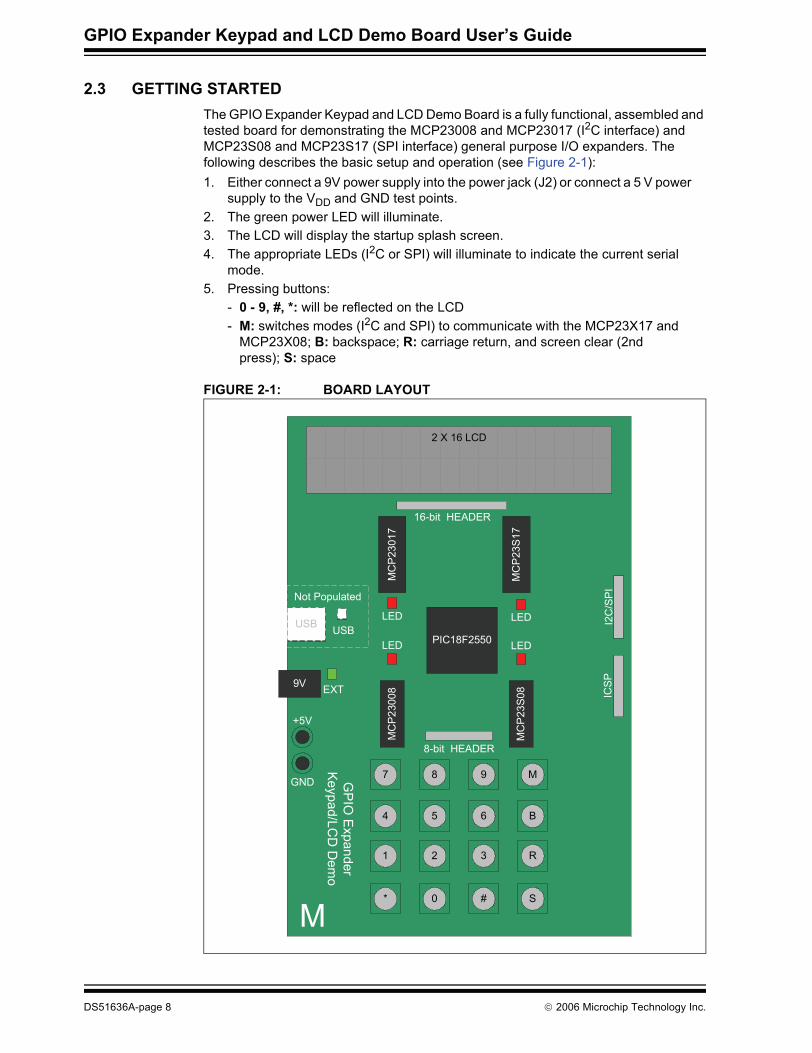
2.3 GETTING STARTEDThe GPIO Expander Keypad and LCD Demo Board is a fully functional, assembled and tested board for demonstrating the MCP23008 and MCP23017 (I2C interface) and MCP23S08 and MCP23S17 (SPI interface) general purpose I/O expanders. The following describes the basic setup and operation (see Figure 2-1):1. Either connect a 9V power supply into the power jack (J2) or connect a 5 V power
supply to the VDD and GND test points.2. The green power LED will illuminate.3. The LCD will display the startup splash screen.4. The appropriate LEDs (I2C or SPI) will illuminate to indicate the current serial
mode.5. Pressing buttons:
- 0 - 9, #, *: will be reflected on the LCD- M: switches modes (I2C and SPI) to communicate with the MCP23X17 and
MCP23X08; B: backspace; R: carriage return, and screen clear (2nd press); S: space
FIGURE 2-1: BOARD LAYOUT
PIC18F2550USB
ICSPEXT
M
LED
MC
P23
017
MC
P23
S17
MC
P230
08
MC
P23
S08
* 0 # S
1 2 3 R
4 5 6 B
7 8 9 M
2 X 16 LCD
16-bit HEADER
8-bit HEADER
LEDLED
LED
I2C
/SP
I
9V
USB
GND
+5V
Not Populated
GP
IO Expander
Keypad/LC
D D
emo
DS51636A-page 8 © 2006 Microchip Technology Inc.

Installation and Operation
2.4 GPIO EXPANDER KEYPAD AND LCD DEMO BOARD DESCRIPTION
2.4.1 Major Board ComponentsThe functional block diagram is shown in Figure 2-2.
FIGURE 2-2: FUNCTIONAL BLOCK DIAGRAM
1. The GPIO BLOCK contains the MCP23X17 and MCP23X08 GPIO Expanders. Two (2) MCP23X17 devices are connected to the LCD module and two (2) MCP23X08 devices are connected to the keypad matrix.A button on the keypad toggles between I2C and SPI mode. When in I2C mode, the MCP23017 and MCP23008 are controlled by the PIC MCU. When in SPI mode, the MCP23S17 and MCP23S08 are controlled. Only one (1) MCP23X08 and one (1) MCP23X17 is on the bus at a time.
2. The CONTROL BLOCK contains the PIC18F4550 and is the main intelligence in the system.
3. The INPUT BLOCK contains the 4x4 keypad matrix. The MCP23X08 devices are used to scan the keys.
4. The OUTPUT BLOCK contains the 2x16 LCD. The MCP23X17 devices control the display.
5. The MCP23X17 and MCP23X08 I/O and serial lines are routed to the HEADER BLOCK to allow the pins to be probed.
6. The PROGRAMMING BLOCK contains the ICSP� header for program-ming/debugging the PIC18F4550.
7. The POWER BLOCK contains the MCP1702 5V voltage regulator. The board can be powered by a 9V supply (connected through the power jack) or by applying 5V directly to the power points.
Control
Power
GPIO
Header
OUTIN
Programming
2 X 16 LCD
Input Output
© 2006 Microchip Technology Inc. DS51636A-page 9

GPIO Expander Keypad and LCD Demo Board User�s Guide
2.5 FIRMWARE DESCRIPTIONSee Figure 2-3 for the main firmware flow diagram.Main Function:1. The firmware first configures the PIC MCU.2. The MCP23X08 and MCP23X17 devices are configured. I2C Devices are
selected first by default. The SPI devices I/O are held in reset.3. The LCD splash screen is shown.4. Wait for an interrupt from the MCP23X08. An interrupt will occur when a button
is pressed. Four (4) inputs are configured to interrupt on falling edge. These inputs are for the �columns� of the keypad matrix.
5. After the interrupt occurs, the firmware calls the Scan_Buttons routine.6. Then the Update_LCD routine.
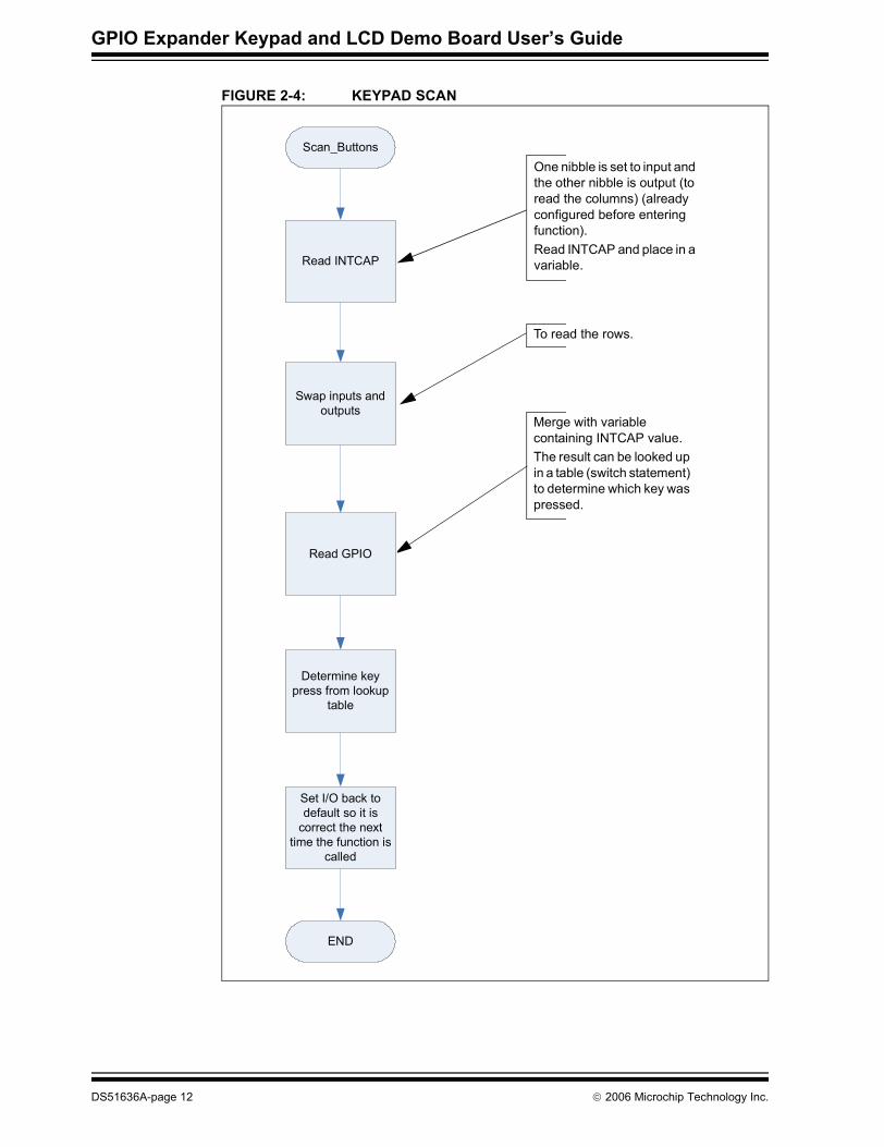
Scan_Buttons Function:1. Read INTCAP register. This register contains a snapshot of the port condition
when the interrupt occurred.2. Swap inputs and outputs so the rows can be read.3. Read GPIO register and merge with variable containing INTCAP value.4. The pressed key is determined by looking up the result in a lookup table.
Update_LCD Function:1. The LCD is updated based on which button was pressed.
DS51636A-page 10 © 2006 Microchip Technology Inc.

Installation and Operation
FIGURE 2-3: MAIN FIRMWARE FLOW
Start
Init_MCU
Init_MCP
GPIO INT Flag Set?
YES
NO
Splash
Scan_Buttons
Update_LCD
The MCP23X08 is configured to interrupt on falling edge for the columns (4 inputs)
After the interrupt, the column location of the button is known and is contained in INTCAP. Need to read GPIO to get the Row location.
Buttons:0-9, #, * : Copied to the LCDM: Toggle mode (SPI and I2C�)B: BackspaceR: Carriage ReturnS: Space
© 2006 Microchip Technology Inc. DS51636A-page 11
GPIO Expander Keypad and LCD Demo Board User�s Guide
FIGURE 2-4: KEYPAD SCAN
One nibble is set to input and the other nibble is output (to read the columns) (already configured before entering function).Read INTCAP and place in a variable.
To read the rows.
Merge with variable containing INTCAP value.The result can be looked up in a table (switch statement) to determine which key was pressed.
Scan_Buttons
Read INTCAP
Read GPIO
Set I/O back to default so it is
correct the next time the function is
called
END
Swap inputs and outputs
Determine key press from lookup
table
DS51636A-page 12 © 2006 Microchip Technology Inc.

Installation and Operation
FIGURE 2-5: LCD UPDATE
Update_LCD
Button Press?
The pressed button result comes from the variable in the Scan_Buttons function
Backspace Space
Carriage Return Display *
Display #Display
Toggle Serial Mode
(I2C or SPI)
B
1 - 9
S
#
M
R
*
END
© 2006 Microchip Technology Inc. DS51636A-page 13

GPIO Expander Keypad and LCD Demo Board User�s Guide
NOTES:
DS51636A-page 14 © 2006 Microchip Technology Inc.
GPIO EXPANDER KEYPADAND LCD DEMO BOARD
USER�S GUIDE
Appendix A. Schematics and Board Layouts
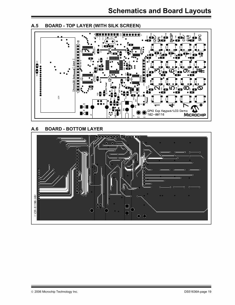
A.1 INTRODUCTIONThis appendix contains the schematic and PCB layout for the GPIO Expander Keypad and LCD Demo Board. Diagrams included:� Board Schematics - Pages 1 - 3.� Board - Top Layer (with silk screen)� Board - Bottom Layer
© 2006 Microchip Technology Inc. DS51636A-page 15

GPIO Expander Keypad and LCD Demo Board User�s Guide
A.2 BOARD SCHEMATIC - PAGE 1
M
DS51636A-page 16 © 2006 Microchip Technology Inc.
Schematics and Board Layouts
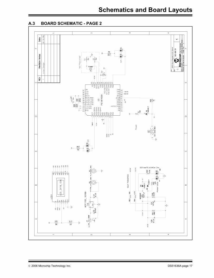
A.3 BOARD SCHEMATIC - PAGE 2
M
© 2006 Microchip Technology Inc. DS51636A-page 17
GPIO Expander Keypad and LCD Demo Board User�s Guide
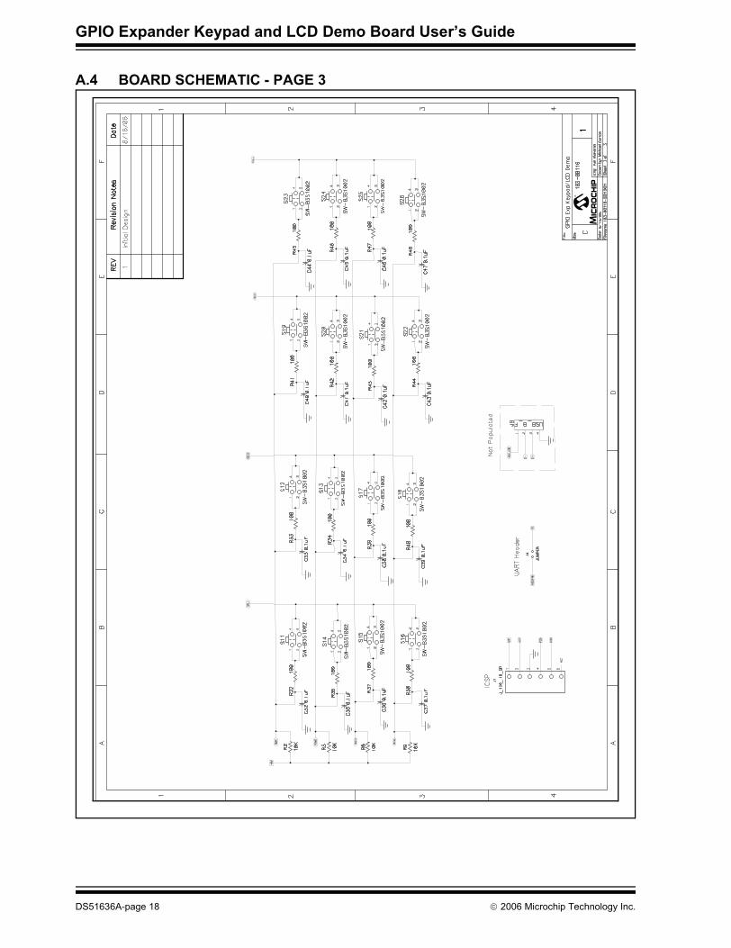
A.4 BOARD SCHEMATIC - PAGE 3
M
DS51636A-page 18 © 2006 Microchip Technology Inc.
Schematics and Board Layouts
A.5 BOARD - TOP LAYER (WITH SILK SCREEN)
A.6 BOARD - BOTTOM LAYER
© 2006 Microchip Technology Inc. DS51636A-page 19

GPIO Expander Keypad and LCD Demo Board User�s Guide
NOTES:
DS51636A-page 20 © 2006 Microchip Technology Inc.

GPIO EXPANDER KEYPADAND LCD DEMO BOARD
USER�S GUIDE
Appendix B. Bill Of Materials (BOM)
TABLE B-1: BILL OF MATERIALS
Qty ReferenceDesignator Description Manufacturer Part Number
23 C1, C5, C6 C15, C25, C30, C31, C32, C33, C34, C35, C36, C37, C38, C39, C40, C41, C42, C43, C44, C45, C46, C47, C48
CAP 1UF 16V CERAMIC Y5V 0805 Panasonic® - ECG ECJ-2VF1C105Z
1 C3 CAP CER .33UF 16V Y5V 0805 Murata Electronics® North America
GRM219F51C334ZA01D
2 C16, C17 CAP 22PF 50V CERM CHIP 0805 SMD *Do Not Populate*
Panasonic - ECG ECJ-2VC1H220J
1 C18 CAP .22UF 16V CERAMIC X7R 0805 Panasonic - ECG ECJ-2VB1C224K4 D1, D2, D3, D4 LED 636NM SUPER RED 0805 SMD LITE-ON INC SML-LX0805SIC-TR2 D5, D6 DIODE SCHOTTKY 20V 0.5A SOD123 ON Semiconductor® MBR0520LT1G2 D7, D8 LED THIN 565NM GRN DIFF 0805
SMDOptoelectronics SML-LXT0805GW-TR
1 D9 RECT SCHOTTKY 1A 20V DO-214AA Micro Commercial Co. SMB5817-TP4 EA Corner BUMPON X-TALL TAPER SQ
.81X.30BK3M/ESM SJ-5523 (BLACK)
1 J1 *Do Not Populate* � �1 J2 CONN POWER JACK 2.5MM PCB
CIRCCUI Inc PJ-102B
1 J3 *Do Not Populate* � �1 J4 *Do Not Populate* � �2 J5, J10 *Do Not Populate* � �1 J9 CONN USB RTANG FEMALE TYPE B
PCB *Do Not Populate*Assmann Electronics Inc
AU-Y1007-R
1 LCD1 LCD_2x16 Fema CG1626-SGR16 R1, R2, R3,
R8, R9, R53RES 10.0K OHM 1/10W 1% 0805 SMD Panasonic - ECG ERJ-6ENF1002V
2 R4, R5 RES 270 OHM 1/8W 5% 0805 SMD Panasonic - ECG ERJ-6GEYJ271V1 R6 RES 523 OHM 1/8W 1% 0805 SMD Yageo® Corporation RC0805FR-07523RL2 R7, R54 RES 4.70K OHM 1/8W 1% 0805 SMD Yageo Corporation RC0805FR-074K7L3 R24, R25, R35 RES 1.00K OHM 1/10W 1% 0805 SMD Panasonic - ECG ERJ-6ENF1001V2 R29, R30 RES 0.0 OHM 1/8W 5% 0805 SMD Panasonic - ECG ERJ-6GEY0R00VNote 1: The components listed in this Bill of Materials are representative of the PCB assembly. The released BOM
used in manufacturing uses all RoHS-compliant components.
© 2006 Microchip Technology Inc. DS51636A-page 21

GPIO Expander Keypad and LCD Demo Board User�s Guide
16 R32, R33, R34, R36, R37, R38, R39, R40, R41, R42, R43, R44, R45, R46, R47, R48
RES 100 OHM 1/10W 3900PPM 5%0805
Panasonic - ECG ERA-S39J101V
1 R49 RES 33.2K OHM 1/8W 1% 0805 SMD Yageo® Corporation RC0805FR-0733K2L2 R50, R52 RES 475 OHM 1/10W 1% 0603 SMD Panasonic - ECG ERJ-3EKF4750V1 R51 RES 100K OHM 1/8W 5% 0805 SMD Panasonic - ECG ERJ-6GEYJ104V17 S11, S12, S13,
S14, S15, S16, S17, S18, S19, S20, S21, S22, S23, S24, S25, S26, S27
SWITCH TACT 6MM SMD MOM 160GF Omron Electronics Inc B3S-1000
1 TP1 TEST POINT PC MULTI PURPOSE BLK
Keystone Electronics® 5011
1 TP2 TEST POINT PC MULTI PURPOSE RED
Keystone Electronics 5010
1 U1 16 Bit I/O Expander with Serial Interface Microchip Technology Inc
MCP23S17-E/SS
1 U2 8-Bit I/O Expander with SPI Interface Microchip Technology Inc
MCP23S08-E/SS
1 U3 16 Bit I/O Expander with Serial Interface Microchip Technology Inc
MCP23017-E/SS
1 U4 8-Bit I/O Expander with I2C Interface Microchip Technology Inc
MCP23008-E/SS
1 U5 44-Pin, High-Performance, Enhanced Flash, USB Microcontroller
Microchip Technology Inc
PIC18F4550
1 U6 2 μA Low Dropout Positive Voltage Regulator
Microchip Technology Inc
MCP1702T-5002I/CB
1 U7 MOSFET P-CH 20V 850MA SSOT3 Fairchild Semiconductor®
NDS352P
1 Y1 CRYSTAL 20.0000 MHZ SERIES RES *Do Not Populate*
CTS-Frequency Controls
ATS200
TABLE B-1: BILL OF MATERIALS (CONTINUED)
Qty ReferenceDesignator Description Manufacturer Part Number
Note 1: The components listed in this Bill of Materials are representative of the PCB assembly. The released BOM used in manufacturing uses all RoHS-compliant components.
DS51636A-page 22 © 2006 Microchip Technology Inc.

Bill Of Materials (BOM)
NOTES:
© 2006 Microchip Technology Inc. DS51636A-page 23

DS51636A-page 24 © 2006 Microchip Technology Inc.
AMERICASCorporate Office2355 West Chandler Blvd.Chandler, AZ 85224-6199Tel: 480-792-7200 Fax: 480-792-7277Technical Support: http://support.microchip.comWeb Address: www.microchip.comAtlantaAlpharetta, GA Tel: 770-640-0034 Fax: 770-640-0307BostonWestborough, MA Tel: 774-760-0087 Fax: 774-760-0088ChicagoItasca, IL Tel: 630-285-0071 Fax: 630-285-0075DallasAddison, TX Tel: 972-818-7423 Fax: 972-818-2924DetroitFarmington Hills, MI Tel: 248-538-2250Fax: 248-538-2260KokomoKokomo, IN Tel: 765-864-8360Fax: 765-864-8387Los AngelesMission Viejo, CA Tel: 949-462-9523 Fax: 949-462-9608Santa ClaraSanta Clara, CA Tel: 408-961-6444Fax: 408-961-6445TorontoMississauga, Ontario, CanadaTel: 905-673-0699 Fax: 905-673-6509
ASIA/PACIFICAsia Pacific OfficeSuites 3707-14, 37th FloorTower 6, The GatewayHabour City, KowloonHong KongTel: 852-2401-1200Fax: 852-2401-3431Australia - SydneyTel: 61-2-9868-6733Fax: 61-2-9868-6755China - BeijingTel: 86-10-8528-2100 Fax: 86-10-8528-2104China - ChengduTel: 86-28-8665-5511Fax: 86-28-8665-7889China - FuzhouTel: 86-591-8750-3506 Fax: 86-591-8750-3521China - Hong Kong SARTel: 852-2401-1200 Fax: 852-2401-3431China - QingdaoTel: 86-532-8502-7355Fax: 86-532-8502-7205China - ShanghaiTel: 86-21-5407-5533 Fax: 86-21-5407-5066China - ShenyangTel: 86-24-2334-2829Fax: 86-24-2334-2393China - ShenzhenTel: 86-755-8203-2660 Fax: 86-755-8203-1760China - ShundeTel: 86-757-2839-5507 Fax: 86-757-2839-5571China - WuhanTel: 86-27-5980-5300Fax: 86-27-5980-5118China - XianTel: 86-29-8833-7250Fax: 86-29-8833-7256
ASIA/PACIFICIndia - BangaloreTel: 91-80-4182-8400 Fax: 91-80-4182-8422India - New DelhiTel: 91-11-4160-8631Fax: 91-11-4160-8632India - PuneTel: 91-20-2566-1512Fax: 91-20-2566-1513Japan - YokohamaTel: 81-45-471- 6166 Fax: 81-45-471-6122Korea - GumiTel: 82-54-473-4301Fax: 82-54-473-4302Korea - SeoulTel: 82-2-554-7200Fax: 82-2-558-5932 or 82-2-558-5934Malaysia - PenangTel: 60-4-646-8870Fax: 60-4-646-5086Philippines - ManilaTel: 63-2-634-9065Fax: 63-2-634-9069SingaporeTel: 65-6334-8870Fax: 65-6334-8850Taiwan - Hsin ChuTel: 886-3-572-9526Fax: 886-3-572-6459Taiwan - KaohsiungTel: 886-7-536-4818Fax: 886-7-536-4803Taiwan - TaipeiTel: 886-2-2500-6610 Fax: 886-2-2508-0102Thailand - BangkokTel: 66-2-694-1351Fax: 66-2-694-1350
EUROPEAustria - WelsTel: 43-7242-2244-39Fax: 43-7242-2244-393Denmark - CopenhagenTel: 45-4450-2828 Fax: 45-4485-2829France - ParisTel: 33-1-69-53-63-20 Fax: 33-1-69-30-90-79Germany - MunichTel: 49-89-627-144-0 Fax: 49-89-627-144-44Italy - Milan Tel: 39-0331-742611 Fax: 39-0331-466781Netherlands - DrunenTel: 31-416-690399 Fax: 31-416-690340Spain - MadridTel: 34-91-708-08-90Fax: 34-91-708-08-91UK - WokinghamTel: 44-118-921-5869Fax: 44-118-921-5820
WORLDWIDE SALES AND SERVICE
10/19/06


