184
| Date post: | 05-May-2018 |
| Category: |
Documents |
| Upload: | nguyenhanh |
| View: | 220 times |
| Download: | 2 times |


General InformationII Who We AreIII Custom DesignsIV Reference Guide
GPO® Products2 GPO Specifications3 Flange Mounts5 Thread-In Shrouds9 Press-In Shrouds11 Hermetic Shrouds13 PCB Mounts16 Right Angle PCB Mounts17 Edge Mounts19 Surface Mounts21 Cable Connectors34 Loads35 Hermetic Seals35 Blindmate Interconnects38 Pins
GPPO® Products40 GPPO Specifications41 Flange Mounts41 Thread-In Shrouds44 Hermetic Shrouds46 PCB Mounts48 Edge Mounts51 Surface Mounts52 Cable Connectors60 Loads61 Hermetic Seals62 Blindmate Interconnects64 Pins
G3PO™ Products66 G3PO Specifications67 PCB Mounts67 Edge Mounts68 Surface Mount69 Cable Connectors70 Loads71 Blindmate Interconnects72 Pin
GMS® Products74 GMS Specifications75 Flange Mounts79 Thread-In Shrouds80 Edge Mount81 Cable Connectors91 Loads92 ESD
SGMS™ Products95 Flange Mounts96 Thread-in Shrouds97 Cable Connectors98 Blindmate Interconnect
Multiposition Block Products100 GPO Multiposition Blocks101 GPPO Multiposition Blocks107 G3PO Multiposition Blocks109 SGMS Multiposition Blocks
Adapters112 GPO Within Series Adapters114 GPO Between Series Adapters123 GPPO Within Series Adapters123 GPPO Between Series Adapters128 G3PO Adapters128 GMS Adapters134 GMS ESD Adapters
Tools138 GPO Tools143 GPPO Tools146 G3PO Tools147 GMS Tools148 Miscellaneous Tools
Appendix150 Cable Assemblies151 Test Capabilities152 Connector Evaluation Kits153 Adapter Matrices154 Assembly Procedures159 Application Notes170 Index
Table of Contents

Corning Gilbert, Inc. Microwave Push-on Interconnects
Who We Are
With 50 years of leading-edge design experience,Corning Gilbert exceeds industry standards with highperformance coaxial connectors for broadbandtelecommunication and microwave systems. CorningGilbert pioneered the GPO® GPPO® and G3PO™
connectors—setting the industry gold standard forcoaxial push-on interconnects. First developed fordemanding military applications, these systems areincreasingly seen as the high frequency interconnectsof choice for military, satellite, wireless andtelecommunications applications.
Our goal is to provide design engineers with highperformance interconnect solutions that can be easilyintegrated into today's sophisticated applications.Our dedicated facility for microwave products enablesus to provide exceptional customer and design serviceswith excellent delivery and unparalleled quality.Our manufacturing facility is designed to provide bothdesign flexibility and cost effective components that arecontrolled to extremely tight tolerances.
Corning Gilbert operates its manufacturing facilitiesunder the ISO 9001 quality system. Headquartered inGlendale, AZ, its state-of-the art facilities adhere tostringent production guidelines to provide our cus-tomers with the highest level of reliability, consistencyand quality, while meeting applicable military andcommercial standards.
Corning Gilbert is a wholly owned subsidiary ofCorning Incorporated. Established in 1851, Corningcreates leading edge technologies for the fastest
growing markets of the world's economy. Corningmanufactures optical fiber, cable and photonic productsfor the telecommunications industry, and highperformance display components for computers,television, and their communications related industries.Corning also uses advanced materials to manufactureproducts for scientific, semiconductor andenvironmental markets.
Customer Care
Our knowledgeable staff is available Monday - Fridayto provide prompt assistance with your order place-ment and shipment inquiries. Let our customer careteam answer your questions or suggest alternative, effi-cient ways of achieving your interconnect objectives.
phone: 800 651 8869 (U.S. and Canada)(01) 623 845 5613 (International)
e-mail: [email protected]
II

Corning Gilbert, Inc. Microwave Push-on Interconnects III
Custom Designs
Custom designs are supported by a team of innovativeengineers, technicians, and machinists at CorningGilbert. Our highly skilled staff will help you defineyour requirements and customize a design for theapplication. We understand that the goal is to quicklydesign and manufacture these specialized interconnectsfor electrical, mechanical, and environmental evalua-tion.
Corning Gilbert offers various custom design solutionsincluding multiposition blocks, hermetic shrouds,cable connectors, PCB mounts, blindmate intercon-nects (BMI), loads, and adapters. Special packaging isalso available, such as custom trays and tape & reel forautomated pick and placement. Other custom optionsinclude selective plating and solder dipping.A typical design cycle begins with a discussion betweenthe applications engineer and the customer to identifythe interconnect requirements. Our library of designsare used as a basis for assessing your needs so that yourexact requirements may be met with the highestefficiency. After receipt of order, our design engineerwill create 3D CAD models which are optimized forelectrical performance using electromagnetic simula-tion software. This allows tuning for a specificfrequency range or broadband performance. Complexdesigns may require mechanical analysis using finiteelement analysis (FEA) software.
Complete with high precision Swiss turning centersand CNC mills, our dedicated machine shop isequipped to produce the custom designs you need. Wealso maintain a plating shop which enables same-daypassivation or plating of metallic components. Manyvalidation tests are performed in-house. Electrical testsinclude voltage standing wave ratio (VSWR), dielectricwithstanding voltage (DWV) and insulation resistance.Mechanical tests include durability and mating forces.Environmental tests include thermal cycling, humidity,and salt spray. Contact our customer care team formore information.
How to Reach Us
Corning Gilbert Inc.Corporate Headquarters5310 West Camelback Rd.Glendale, AZ 85301 U.S.A.phone: 800 651 8869 (U.S. and Canada)
(01) 623 845 5613 (International)fax: (01) 623 934 5160website: www.corning.com/corninggilberte-mail: [email protected]
International Customer Service Centerat Corning CabelconIndustriparken 104760 VordinborgDenmarkphone: +(45) 55 98 55 99fax: +(45) 55 98 55 04website: www.cabelcon.dke-mail: [email protected]
Symbols
Standard Tolerances
All dimensions are in inches, interpretation perANSI Y14.5.
.XX ± .010
.XXX ± .005Fractions ± 1/64Angular ± 5ºTypical machine surface finish 63 micro inches
Common Materials and Finishes
• Beryllium copper per ASTM B 196 and/or ASTM B 197. Gold plate per ASTM B 488 over electrolytic nickel per SAE AMS QQ N 290.
• CRES 303 per ASTM A 484 and ASTM A 582 or ASTM A 555 and ASTM A 581. Passivate per SAE AMS 2700.
• Brass per ASTM B 16. Gold plate per ASTM B 488 over electrolytic nickel per SAE AMS QQ N290.
• Virgin TEFLON® PTFE fluorocarbon per ASTM D 1710.
• KOVAR® Iron-nickel-cobalt sealing alloy per ASTM F 15. Gold plate per ASTM B 488 over electrolytic nickel per SAE AMS QQ N 290.
• Corning® 7070 glass.
• Ultem® 1000 (Polyetherimide) per ASTM D 5205.
• Torlon® (Polyamide-Imide) per ASTM D 5204.
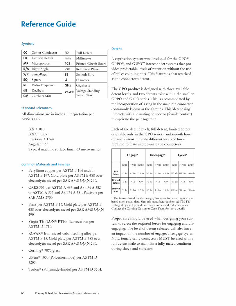
Detent
A captivation system was developed for the GPO®,GPPO®, and G3PO™ interconnect systems that pro-vides predictable levels of retention without the useof bulky coupling nuts. This feature is characterizedas the connector's detent.
The GPO product is designed with three availabledetent levels, and two detents exist within the smallerGPPO and G3PO series. This is accommodated bythe incorporation of a ring in the male pin connector(commonly known as the shroud). This 'detent ring'interacts with the mating connector (female contact)to captivate the pair together.
Each of the detent levels, full detent, limited detent(available only in the GPO series), and smooth bore(or zero detent) provide different levels of forcerequired to mate and de-mate the connectors.
* The figures listed for the engage/disengage forces are typical andbased upon actual data. Shrouds manufactured from ASTM-F15sealing alloys will provide increased forces and reduced cycles.Contact the Corning Customer Care Team for more details.
Proper care should be used when designing your sys-tem to select the required forces for engaging and dis-engaging. The level of detent selected will also havean impact on the number of engage/disengage cycles.Note, female cable connectors MUST be used with afull detent male to maintain a fully mated conditionduring shock and vibration.
CC Center Conductor
LD Limited Detent
MP Microporous
R/A Right Angle
S/R Semi-Rigid
SQ Square
RF Radio Frequency
dB Decibels
CM Catchers Mitt
Corning Gilbert, Inc. Microwave Push-on InterconnectsIV
Reference Guide
FullDetent
LimitedDetent
SmoothBore
GPO GPPO G3PO GPO GPPO G3PO GPO GPPO
Engage* Disengage* Cycles*
G3PO
7.0 lbs 4.5 lbs 2.5 lbs 9.0 lbs 6.5 lbs 4.5 lbs 100 min 100 min 100 min
5.0 lbs N/A N/A 7.0 lbs N/A N/A 500 min N/A N/A
2.0 lbs 2.5 lbs 1.2 lbs 0.5 lbs 1.5 lbs 1.0 lbs 1000 min 500 min 500 min
FD Full Detent
mm Millimeter
PCB Printed Circuit Board
R/P Reference Plane
SB Smooth Bore
Ø Diameter
GHz Gigahertz
VSWR Voltage Standing Wave Ratio


General Characteristics
Impedance Frequency rangeTemperature range
Electrical Characteristics
VSWRInsertion lossDWV@ Sea Level:Insulation resistanceContact resistance
Outer conductorInner conductor
RF leakage
Mechanical Characteristics
Mate/Demate Cycles
Force to engage/disengage
Tolerated misalignmentRadialAxial
Environmental Characteristics
Thermal ShockSalt SprayVibrationShockMoisture resistance
Materials (typical)
BodiesOuter contactsCenter contactsInsulatorsSprings
Finish (typical)
Bodies
Contacts
*Note: Corning Gilbert male connectors have a full self-centering mechanism
50 ohms nominalDC to 40 GHz-55oC thru 165oC
1.15:1 to 26.5 GHz typical; <1.5:1 typical to 40 GHz.12 f GHz500 Vrms5,000 megohms min.
2 milliohms max.6 milliohms max.-80 dB to 3 GHz, -65 dB to 26.5 GHz
FD - 100min.; LD - 500min.; SB - 1000min.;FD - 9.0lbs.typ./7.0lbs.typ.; LD - 7.0lbs.typ./5.0lbs.typ.SB - 2.0lbs.typ./.5lbs.typ.
+/- 0.010”0.010” (flush to 0.010” from the reference plane)
MIL-STD-202, Method 107, Condition BMIL-STD-202, Method 101MIL-STD-202, Method 204MIL-STD-202, Method 213, Condition IMIL-STD-202, Method 106, except Step 7B
Beryllium Copper per ASTM B196 and or/ASTM B197Beryllium Copper per ASTM B196 and or/ASTM B197Beryllium Copper per ASTM B196 and or/ASTM B197PTFE Fluorocarbon per ASTM D1710 and ASTM D 145717-7 Stainless Steel per ASTM A313-95A
Gold plated per MIL-G-45204, Type I, Grade C, Class 1,Over Nickel Plate per QQ-N-290Gold plated per MIL-G-45204, Type I, Grade C, Class 1,Over Nickel Plate per QQ-N-290
GPO Specifications
Corning Gilbert, Inc. Microwave Push-on Interconnects2

GPO Flange Mounts
Catalog Number A B Cø Dø
A001-A23-03 FD .328 .480 .098A001-A24-03 LD .328 .480 .098A001-A25-03 SB .328 .480 .098A001-A23-04 FD .282 .400 .073A001-A24-04 LD .282 .400 .073A001-A25-04 SB .282 .400 .073A001-A23-07 FD .481 .625 .103A001-A24-07 LD .481 .625 .103A001-A25-07 SB .481 .625 .103
Tools Recommended
A090-A99-11 (For-03 Series)
A090-A99-10 (For-04 Series)
A090-A99-09 (For-07 Series)
A090-A99-03
Assembly Procedure
AP01-009
Male Flange MountShroud No Center Conductor
Male Flange MountShroud Accepts 0.012 Center Conductor
Catalog Number A
A001-N33-02 FDA001-N34-02 LDA001-N35-02 SB
VSWR (TYP)
1.2:1 to 18 GHz
1.35:1 to 26.5 GHz
Tools Recommended
A090-A99-09
Catalog Number A
A001-N33-05 FDA001-N34-05 LDA001-N35-05 SB
VSWR (TYP)
1.25:1 to 12 GHz
1.35:1 to 26.5 GHz
Tools Recommended
A090-A99-09Male 2 Hold Flange Mount
Corning Gilbert, Inc. Microwave Push-on Interconnects 3

GPO Flange Mounts
Catalog Number A
0119-441-3 FD
VSWR (TYP)
1.25:1 to 18 GHz
1.35:1 to 26.5 GHz
Male Full Detent 2 Hole Flange Mount Straight Terminal
Catalog Number
0119-467-3
VSWR (TYP)
1.25:1 to 18 GHz
1.35:1 to 26.5 GHz
Male Full Detent Right Angle Flange Mount
Catalog Number
0119-785-3
Tools Recommended
A090-A99-11
A090-A99-03
Male Flange Mount Full Detent LimitedHub 1/2 Hole
Corning Gilbert, Inc. Microwave Push-on Interconnects4

GPO Thread-In Shrouds
GPO Flange Mounts
Male Thread-in Shroud No CenterConductor
Catalog Number A
A003-A23-01 FDA003-A24-01 LDA003-A25-01 SB
Tools Recommended
A090-A99-01
Assembly Procedure
AP01-024
Modified Catchers MittThread-in Shroud
Catalog Number
A003-A27-01
Tools Recommended
A097-A99-03
Male Flange Mount Full DetentLimited Hub
Catalog Number
0119-857-3
Tools Recommended
A090-A99-10
A090-A99-03
Assembly Procedure
AP01-009
Corning Gilbert, Inc. Microwave Push-on Interconnects 5

GPO Thread-In Shrouds
Female Thread-inWaveguide Launch
Catalog Number
A003-L11-01
Male Thread-inStraight Terminal
Male Thread-in Shroud 0.018 Pin Contact
Catalog Number A
A003-L33-02 FDA003-L34-02 LDA003-L35-02 SB
VSWR (TYP)
1.25:1 to 18 GHz
1.35:1 to 26.5 GHz
Tools Recommended
A097-A99-01 for FD
A097-A99-02 for LD
A097-A99-03 for SB
Corning Gilbert, Inc. Microwave Push-on Interconnects6
Catalog Number A
A003-L33-01 FDA003-L34-01 LDA003-L35-01 SB
VSWR (TYP)
1.25:1 to 18 GHz
1.35:1 to 26.5 GHz
Tools Recommended
A097-A99-01 for FD
A097-A99-02 for LD
A097-A99-03 for SB

GPO Thread-In Shrouds
Male Thread-in Shroud 2.92 mm Sparkplug
Catalog Number A
A003-N33-01 FDA003-N34-01 LDA003-N35-01 SB
VSWR (TYP)
1.25:1 to 18 GHz
1.35:1 to 26.5 GHz
Tools Recommended
A097-A99-01 for FD
A097-A99-02 for LD
A097-A99-03 for SB
A097-A99-07
Assembly Procedure
AP01-104
Male Thread-in Shroud Accepts 0.012 Pin
Catalog Number A
A003-N33-02 FDA003-N34-02 LDA003-N35-02 SB
VSWR (TYP)
1.25:1 to 18 GHz
1.35:1 to 26.5 GHz
Tools Recommended
A097-A99-01 for FD
A097-A99-02 for LD
A097-A99-03 for SB
A097-A99-07
GPO FemaleThread-in
Catalog Number
0119-228-1
VSWR (TYP)
1.25:1 to 18 GHz
1.35:1 to 26.5 GHz
.218ACROSS
FLATS
.248Ø
.131Ø
.245
.101
.025
#12-56 UNS-2A
GPO FEMALEINTERFACE
Corning Gilbert, Inc. Microwave Push-on Interconnects 7

GPO Thread-In Shrouds
Male Thread-in Non-hermetic Straight Terminal
Catalog Number A
0119-258-3-FD FD0119-258-3-LD LD0119-258-3-SB SB
VSWR (TYP)
1.25:1 to 18 GHz
1.35:1 to 26.5 GHz
Tools Recommended
A090-A99-01 for FD
A090-A99-02 for LD
A090-A99-03 for SB
Male Thread-in Waveguide Launch
Catalog Number A
0119-265-3-FD FD0119-265-3-LD LD0119-265-3-SB SB
Male Thread-in Waveguide Launch
Catalog Number A
0119-266-3-FD FD0119-266-3-LD LD0119-266-3-SB SB
Corning Gilbert, Inc. Microwave Push-on Interconnects8

GPO Thread-In Shrouds
Male Catchers Mitt to Straight Terminal
Catalog Number A B
0119-424-3-1 .067-.073 .0400119-424-3-2 .097-.103 .0400119-424-3-3 .200 .1100119-424-3-4 .350 .260
VSWR (TYP)
1.35:1 to 18 GHz
1.45:1 to 26.5 GHz
Tools Recommended
A090-A99-03
Assembly Procedure
AP01-057
Male to Male Full DetentThread-in
Catalog Number
0119-579-3
VSWR (TYP)
1.25:1 to 18 GHz
1.35:1 to 26.5 GHz
Tools Recommended
A090-A99-01
GPO Press-In Shrouds
Male Press-in Shroud No Center Conductor
Catalog Number A Bø C Dø
A005-A23-01 FD .174 .120 .170A005-A24-01 LD .174 .120 .170A005-A25-01 SB .174 .120 .170A005-A23-02 FD .154 .080 .143A005-A24-02 LD .154 .080 .143A005-A25-02 SB .154 .080 .143
Tools Recommended
A090-A99-08
Corning Gilbert, Inc. Microwave Push-on Interconnects 9

GPO Press-In Shrouds
Male Limited DetentPress-in Straight Terminal
Catalog Number
A005-L34-01
VSWR (TYP)
1.25:1 to 18 GHz
1.35:1 to 26.5 GHz
Tools Recommended
A090-A99-08
Assembly Procedure
AP01-070
.158Ø
.156Ø
R/P
30°2 PL. .195
.189.115.105
.065
.055KNURL
.044
.038.069.061
.058Ø
.056Ø
.0835
.0795
DIELECTRIC
.019Ø
.017Ø
GPO MALELIMITED DETENTINTERFACE
50 TPI STRAIGHT KNURLPER ASME B94.6(.005 MIN. TOOTH DEPTH)BLANK DIA. .156Ø - .158ØRAISED TO .167Ø - .169Ø
Male Smooth Bore Press-in Straight Terminal
Catalog Number
A005-L35-01
VSWR (TYP)
1.25:1 to 18 GHz
1.35:1 to 26.5 GHz
Tools Recommended
A090-A99-08
Assembly Procedure
AP01-070
.158Ø
.156Ø
R/P
.195
.189.115.105
.065
.055KNURL
.044
.038.069.061
.058Ø
.056Ø
.0835
.0795
DIELECTRIC
.019Ø
.017Ø
GPO MALESMOOTH BOREINTERFACE
50 TPI STRAIGHT KNURLPER ASME B94.6(.005 MIN. TOOTH DEPTH)BLANK DIA. .156Ø - .158ØRAISED TO .167Ø - .169Ø
Male Full DetentR/A Press-in Accepts 0.015 C/C
Catalog Number
A006-N33-02
VSWR (TYP)
1:3:1 to 18 GHz
BODY CORNERS
TIPS ONLY
.008 A
.001 A
.180
.160 2 PL.
.010 A C Ø.425 BODY
Ø.438
.2635
TIP TO TIP
TIP TO TIP
.010 A B
.175
.1552 PL.
W
B
C
SZ Y
X
.2502 PL.
D
T
U V
R.0584 PL.
R.065 MIN2 PL.
.214MAX
.268MAX
.161
A.006.002
.015
.011
.062
.058
.003 MIN X 45°
GPO MALEFULL DETENTINTERFACE
Ø.003 A B
.164MAX
.192MAX
.015 MIN X 45°
.012
.008 x 45° 4 PL.
ACCEPTS .015Ø-.016Øx .050 MAX LONG PINWITH SPHERICALRADIUS TIP
Ø.003 A B C
.150
.140
R / P
Corning Gilbert, Inc. Microwave Push-on Interconnects10

GPO Hermetic Shrouds
Male Hermetic Shroud Full Shroud Full Body
Catalog Number A “L” Lengths
A007-L43-01-TAB-X FD .030/.050/.070/.090A007-L44-01-TAB-X LD .030/.050/.070/.090A007-L45-01-TAB-X SB .030/.050/.070/.090
TAB = “L” x 103 inches
X = Customer defined. Straight (S) or Radius (R) cut.
VSWR (TYP)
1.25:1 to 18 GHz
1.35:1 to 26.5 GHz
Male Hermetic Shroud Half Shroud Full Body
Catalog Number A “L” Lengths
A007-L43-02-TAB-X FB .030/.050/.070/.090A007-L44-02-TAB-X LD .030/.050/.070/.090A007-L45-02-TAB-X SB .030/.050/.070/.090
TAB = “L” x 103 inches
X = Customer defined. Straight (S) or Radius (R) cut.
VSWR (TYP)
1.25:1 to 18 GHz
1.35:1 to 26.5 GHz
Male Hermetic Shroud Full Shroud Short Body
Catalog Number A “L” Lengths
A007-L43-03-TAB-X FD .030/.050/.070/.090A007-L44-03-TAB-X LD .030/.050/.070/.090A007-L45-03-TAB-X SB .030/.050/.070/.090
TAB = “L” x 103 inches
X = Customer defined. Straight (S) or Radius (R) cut.
VSWR (TYP)
1.25:1 to 18 GHz
1.35:1 to 26.5 GHz
Corning Gilbert, Inc. Microwave Push-on Interconnects 11

GPO Hermetic Shrouds
Male Hermetic Shroud Half Shroud Short Body
Catalog Number A “L” Lengths
A007-L43-04-TAB-X FD .030/.050/.070/.090A007-L44-04-TAB-X LD .030/.050/.070/.090A007-L45-04-TAB-X SB .030/.050/.070/.090
TAB = “L” x 103 inches
X = Customer defined. Straight (S) or Radius (R) cut.
VSWR (TYP)
1.25:1 to 18 GHz
1.35:1 to 26.5 GHz
Male Full DetentThread-in Shroud Straight Terminal
.250HEX.
.275ØACROSS
CORNERS
.049
.190
.100
SQUARE CUT
GPO MALEFULL DENTENTINTERFACE
.062
.060
R / P
.015Ø
KOVAR
7070 GLASS
#10-32 UNF-2A
Catalog Number
A007-L43-14
VSWR (TYP)
1.25:1 to 18 GHz
1.35:1 to 26.5 GHz
Male Solder-in Hermetic Shroud
.180
7070 GLASS
FULL RAD.
.112Ø
.118Ø
.012Ø
.020
.014.011.009
.071
.069R / P
KOVARGPO MALE"A" INTERFACE
.190Ø
.016Ø
.014Ø
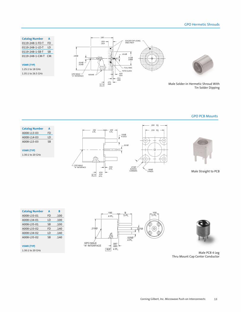
Catalog Number A
0119-248-1-FD FD0119-248-1-LD LD0119-248-1-SB SB0119-248-1-CM CM
VSWR (TYP)
1.25:1 to 18 GHz
1.35:1 to 26.5 GHz
Corning Gilbert, Inc. Microwave Push-on Interconnects12
GPO Hermetic Shrouds
GPO PCB Mounts
Male Solder-in Hermetic Shroud WithTin Solder Dipping
.180
.059
.019
.190Ø
.016Ø
.014Ø
GPO MALE"A" INTERFACE
KOVAR
R / P
.071
.069
.011
.009
.020
.014
7070 GLASS
FULL RAD.
.012Ø
.112Ø
.108Ø
SOLDER DIP USINGSN63 PB37
Male Straight to PCB
.030Ø4 LEGS
.015Ø
.272ØACROSS
CORNERS.068Ø4 PADS
.200 SQ.
.150 SQ..1005 PL.
.1824 PL.
.074
.0704 PL.R / P
GPO MALE"A" INTERFACE .010
4 PL.
Catalog Number A
0119-248-1-FD-T FD0119-248-1-LD-T LD0119-248-1-SB-T SB0119-248-1-CM-T CM
VSWR (TYP)
1.25:1 to 18 GHz
1.35:1 to 26.5 GHz
Catalog Number A
A008-L13-03 FDA008-L14-03 LDA008-L15-03 SB
VSWR (TYP)
1.30:1 to 20 GHz
Male PCB 4 Leg Thru Mount Cap Center Conductor
Catalog Number A B
A008-L33-01 FD .100A008-L34-01 LD .100A008-L35-01 SB .100A008-L33-02 FD .140A008-L34-02 LD .140A008-L35-02 SB .140
VSWR (TYP)
1.30:1 to 20 GHz
Corning Gilbert, Inc. Microwave Push-on Interconnects 13

GPO PCB Mounts
Male PCB 4 Leg Thru Mount Sep C/C
Catalog Number A
A008-L33-05 FDA008-L34-05 LDA008-L35-05 SB
VSWR (TYP)
1.30:1 to 20 GHz
Male Full DetentPCB 3 Pin Thru Hole
.195
.011
.1102 PL.
.028Ø2 PL.
.027Ø
.044Ø2 PL.
.283Ø
GPO MALEFULL DETENTINTERFACE
R / P
.0852 PL.
.214ACROSS
FLATS
.100
.100
Catalog Number
A008-L33-06
VSWR (TYP)
1.30:1 to 20 GHz
Male PCB 4 Leg Thru Mount R/A Center Conductor
Catalog Number A
A008-P33-01 FDA008-P34-01 LDA008-P35-01 SB
VSWR (TYP)
1.30:1 to 20 GHz
Corning Gilbert, Inc. Microwave Push-on Interconnects14

GPO PCB Mounts
Male Smooth Bore Straight to PCB (> 50 ohm)
.030Ø4 LEGS
.015Ø
.272Ø
.217ØACROSS
CORNERS
.068Ø4 PADS
.200 SQ.
.150 SQ..1555 PL.
.1824 PL.
R / P
GPO MALESMOOTH BOREINTERFACE
(.337)
Catalog Number
0119-411-1
VSWR (TYP)
1.30:1 to 20 GHz
Male Limited Detentto PCB with Separate Pin
3/16HEX STOCK
.100SQ
.066Ø
.064Ø.100
.016Ø
.014Ø2 PL.
.006
.004
.060
.029Ø
.027Ø
.010
R / P
.1004 PL.
.025Ø4 PL.
.120
GPO MALELIMITED DETENTINTERFACE
Catalog Number
0119-711-1
VSWR (TYP)
1.30:1 to 20 GHz
Male Straight to PCB
.292
.182 .1005 PL.
.165Ø
GPO MALE 6G"A" INTERFACE
R / P
.084
.080
.028Ø
.024Ø
.042Ø 4 PL.
.025Ø 4 PL.
.1002 PL.
.0502 PL.
Catalog Number A
1619-001-1-FD FD1619-001-1-LD LD1619-001-1-SB SB
VSWR (TYP)
1.30:1 to 20 GHz
Corning Gilbert, Inc. Microwave Push-on Interconnects 15

GPO Right Angle PCB Mounts
Catalog Number A B
A009-P33-01 FD .096A009-P34-01 LD .096A009-P35-01 SB .096A009-P33-03 FD .140A009-P34-03 LD .140A009-P35-03 SB .140
VSWR (TYP)
1.35:1 to 20 GHzMale R/A PCB 4 Leg Thru Mount Cap C/C
30°
.320
.093
.086
.352.190
.205Ø.017Ø
.050
R / P
.154
.146
.025Ø
.023Ø
.100 .115.265
Catalog Number
0119-397-3-100
VSWR (TYP)
1.35:1 to 20 GHz
Male Smooth Bore Catchers Mitt R/A to PCB
.190MAX
.355
.347
.256
.150Ø
.375Ø
.045
.075
.053
GPO MALESMOOTH BOREINTERFACE
.190ØMAX. .170Ø
.027Ø
.023ØCONTACT
.450MAX.
.090.200
.098
.094
R / P
Catalog Number
0119-588-1
VSWR (TYP)
1.35:1 to 20 GHz
Male Smooth Bore Right Angle to PCB
Corning Gilbert, Inc. Microwave Push-on Interconnects16
GPO Right Angle PCB Mounts
Male Catchers MittRight Angle to PCB
.250SQ.
.429
.554
.040
.120
.117SQ.
.375Ø#0-80 UNF - 28 THRU
.125
.140Ø.086Ø
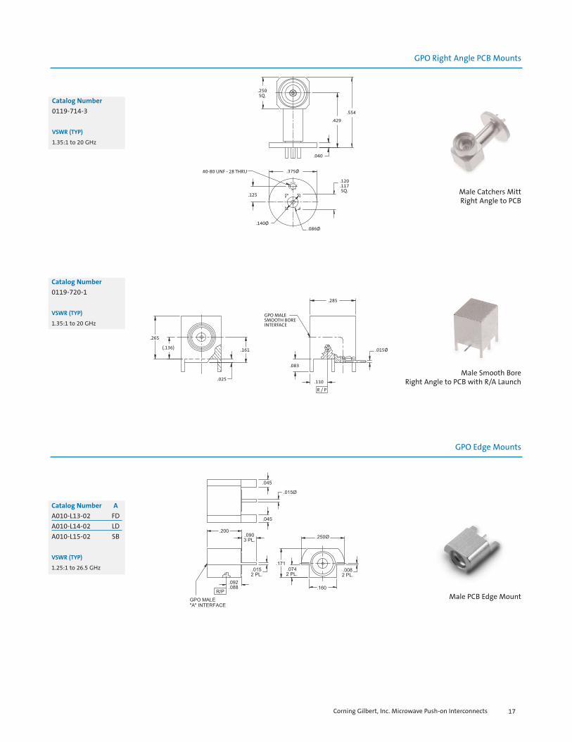
Catalog Number
0119-714-3
VSWR (TYP)
1.35:1 to 20 GHz
Male Smooth BoreRight Angle to PCB with R/A Launch
.265
(.136)
.025
.161
GPO MALESMOOTH BOREINTERFACE
.285
.015Ø
.083
.110
R / P
Catalog Number
0119-720-1
VSWR (TYP)
1.35:1 to 20 GHz
Catalog Number A
A010-L13-02 FDA010-L14-02 LDA010-L15-02 SB
VSWR (TYP)
1.25:1 to 26.5 GHz
Male PCB Edge Mount
Corning Gilbert, Inc. Microwave Push-on Interconnects 17
GPO Edge Mounts

GPO Edge Mounts
Male PCB Edge Mount
Catalog Number A
A010-L33-01 FDA010-L34-01 LDA010-L35-01 SB
VSWR (TYP)
1.25:1 to 26.5 GHz
Catalog Number A
A010-L33-02 FDA010-L34-02 LDA010-L35-02 SB
VSWR (TYP)
1.25:1 to 26.5 GHz
Male PCB Edge Mount
Catalog Number A B
A010-L33-03 FD .099A010-L34-03 LD .099A010-L35-03 SB .099A010-L33-04 FD .069A010-L34-04 LD .069A010-L35-04 SB .069
VSWR (TYP)
1.25:1 to 26.5 GHzMale PCB Edge Mountwith Chassis Mount
Corning Gilbert, Inc. Microwave Push-on Interconnects18

GPO Surface Mounts
Male Solder-on Shroud
Catalog Number A
A012-A93-01 FDA012-A94-01 LDA012-A95-01 SB
Male Limited DetentCatchers Mitt Solder-on Shroud
Catalog Number
A012-A97-01
VSWR (TYP)
1.25:1 to 18 GHz
1.35:1 to 26.5 GHz
Catalog Number
A012-A97-02
VSWR (TYP)
1.25:1 to 18 GHz
1.35:1 to 26.5 GHz
Shroud Solder Mount Smooth BoreCatchers Mitt with Contact and Dielectric
Catalog Number
A012-L76-03
VSWR (TYP)
1.25:1 to 18 GHz
1.35:1 to 26.5 GHz
Corning Gilbert, Inc. Microwave Push-on Interconnects 19
GPO LIMITED DETENTCATCHERS MITTINTERFACE
GPO LIMITED DETENTCATCHERS MITTINTERFACE
.160
.055
.005
.002.040
.230Ø
.220Ø .155Ø
.052
.048R / P.176
.045
.040 .004
.220Ø
.229Ø
.175Ø
.229Ø
.155ØR.079THRUWALL ONE
.059
.069
.051R / P
.164Ø
GPO MALE"A" INTERFACE
.120
.020
.195Ø
.145Ø
.005 x 45° 2 PL.
.011
.009 R/P
.065
.040
GPO SMOOTH BORECATCHERS MITTINTERFACE
.120
.015
.005
.002
.155Ø .270Ø
.111
.109R/P

GPO Surface Mounts
Catalog Number A
A012-P93-01 FDA012-P94-01 LDA012-P95-01 SB
VSWR (TYP)
1.25:1 to 18 GHz
1.35:1 to 26.5 GHz
Male PCB Surface Mount
.050SLOT4 PL.
.121Ø.070Ø
.027
.161
.031GPO MALECATCHERS MITTINTERFACE
.184Ø
.175Ø
.042
.039
R / P
Catalog Number
A012-L96-01
VSWR (TYP)
1.25:1 to 18 GHz
1.35:1 to 26.5 GHz
Shroud Solder Mount Smooth BoreCatchers Mitt with Contact
Catalog Number A
A012-P93-04 FDA012-P94-04 LDA012-P95-04 SB
VSWR (TYP)
1.25:1 to 18 GHz
1.35:1 to 26.5 GHz
Male PCB 4 Leg Thru Mount R/A C/C
Corning Gilbert, Inc. Microwave Push-on Interconnects20
GPO Cable Connectors
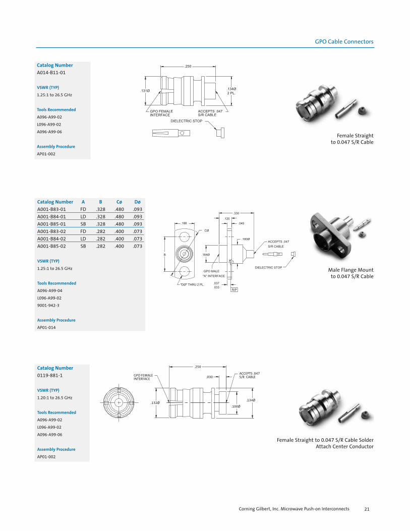
Catalog Number
A014-B11-01
VSWR (TYP)
1.25:1 to 26.5 GHz
Tools Recommended
A096-A99-02
L096-A99-02
A096-A99-06
Assembly Procedure
AP01-002
Female Straightto 0.047 S/R Cable
Male Flange Mountto 0.047 S/R Cable
Catalog Number A B Cø Dø
A001-B83-01 FD .328 .480 .093A001-B84-01 LD .328 .480 .093A001-B85-01 SB .328 .480 .093A001-B83-02 FD .282 .400 .073A001-B84-02 LD .282 .400 .073A001-B85-02 SB .282 .400 .073
VSWR (TYP)
1.25:1 to 26.5 GHz
Tools Recommended
A096-A99-04
L096-A99-02
9001-942-3
Assembly Procedure
AP01-014
Female Straight to 0.047 S/R Cable SolderAttach Center Conductor
Catalog Number
0119-881-1
VSWR (TYP)
1.20:1 to 26.5 GHz
Tools Recommended
A096-A99-02
L096-A99-02
A096-A99-06
Assembly Procedure
AP01-002
Corning Gilbert, Inc. Microwave Push-on Interconnects 21
GPO FEMALEINTERFACE
.132Ø
.250
.030ACCEPTS .047S/R CABLE
.134Ø
.100Ø

GPO Cable Connectors
Catalog Number
A014-D11-01*
VSWR (TYP)
1.25:1 to 26.5 GHz
Tools Recommended
A096-A99-06
L096-A99-01
Assembly Procedure
AP01-114Female Straightto 0.086 S/R Cable
* For a flexible alternative, order A015-K11-06to allow for heat shrink sleeve
Catalog Number
A014-D11-02
VSWR (TYP)
1.25:1 to 26.5 GHz
Tools Recommended
9001-932-3
A096-A99-06
L096-A99-01
Assembly Procedure
AP01-071Male Straightto 0.086 S/R Microporous Cable
Male Flange Mount to0.086 S/R Cable
Catalog Number A B Cø Dø
A001-D83-01 FD .328 .480 .093A001-D84-01 LD .328 .480 .093A001-D85-01 SB .328 .480 .093A001-D83-02 FD .282 .400 .073A001-D84-02 LD .282 .400 .073A001-D85-02 SB .282 .400 .073
VSWR (TYP)
1.35:1 to 26.5 GHz
Tools Recommended
L096-A99-01
A096-A99-04
9001-942-3
Assembly Procedure
AP01-015
Corning Gilbert, Inc. Microwave Push-on Interconnects22

GPO Cable Connectors
Female Straight to 0.086 S/R CableSolder Attach Center Conductor
Catalog Number
0119-399-1
VSWR (TYP)
1.25:1 to 26.5 GHz
Tools Recommended
A096-A99-06
L096-A99-01
9001-932-3
A096-A99-02
Assembly Procedure
AP01-131
Catalog Number
A014-F71-01
VSWR (TYP)
1.10:1 to 4 GHz
Tools Recommended
A096-A99-06
L096-A99-01
A096-A99-02
Assembly Procedure
IS-7804-1Female Straightto RG-316 Cable
Catalog Number
A014-H71-01
VSWR (TYP)
1.15:1 to 4 GHz
Tools Recommended
A096-A99-02
L096-A99-01
A096-A99-06
Assembly Procedure
AP01-039
Female Straightto RG-178/196 Cable
Corning Gilbert, Inc. Microwave Push-on Interconnects 23
GPO FEMALEINTERFACE
.355
.325
.320.180.175
.030
.025
.032
.028
.200Ø
ACCEPTS.086 S/RCABLE
.045Ø THRU ONE SIDE
.152Ø
.148Ø2 PL.
.118Ø
.114ØANTI-ROCK/EMI RING
.132Ø

GPO Cable Connectors
Catalog Number
A014-K11-01
Tools Recommended
A096-A99-02
A096-A99-06
L096-A99-01
Assembly Procedure
AP01-113
Catalog Number
0119-202-1
Tools Recommended
A096-A99-02
L096-A99-02
A096-A99-08
Assembly Procedure
AP01-095
Female Straightto 0.080 Flex Cable
Female to UFF-070D Flex Cable
Female Straightto UFF-070D Flex Cable
Catalog Number
0119-203-1
Tools Recommended
A096-A99-02
L096-A99-02
A096-A99-06
Assembly Procedure
AP01-093
GPO FEMALEINTERFACE
.250
.132Ø .134Ø
ACCEPTS I.W. M1049 (.080)FLEX CABLE
CONTACT SOLDERSTO CABLE CENTERCONDUCTOR
Corning Gilbert, Inc. Microwave Push-on Interconnects24
GPO FEMALEINTERFACE
.315
.132Ø
.265
.133.156
.488
.146Ø
GPO FEMALEINTERFACE
.375ADAPTER INSTALLED
.300
.131Ø

GPO Cable Connectors
Catalog Number
0119-594-1
Tools Recommended
A096-A99-02
L096-A99-01
A096-A99-06
Assembly Procedure
AP01-060
Female Straightto UFF-092A Flex Cable
Female R/Ato 0.047 S/R Cable
Catalog Number
A015-B11-01
VSWR (TYP)
1.20:1 to 18 GHz
1.30:1 to 26.5 GHz
Tools Recommended
A096-A99-07
L096-A99-02
A096-A99-01
Assembly Procedure
AP01-097
Female R/Ato 0.047 S/R Cable
Catalog Number
A015-B11-02
VSWR (TYP)
1.25:1 to 26.5 GHz
Tools Recommended
A096-A99-01
A096-A99-07
L096-A99-02
Assembly Procedure
AP01-097
Corning Gilbert, Inc. Microwave Push-on Interconnects 25
.132Ø
.430
(.250)
(.225)
(.135)
GPO FEMALEINTErFACE
(.112Ø)
(.134Ø)2 PL.
(.128Ø)
ACCEPTS MICRO-COAXUFF 092A FLEX CABLE
.032
CONTACT
CABLE STOP
.231
.132Ø
GPO FEMALEINTERFACE
.230
.192
PORT PLUG
.077Ø
ACCEPTS .047 S/R CABLE

GPO Cable Connectors
Catalog Number
A015-B71-01
VSWR (TYP)
1.25:1 to 26.5 GHz
Tools Recommended
A096-A99-01
A096-A99-07
L096-A99-02
Assembly Procedure
AP01-019
Female R/A to 0.047 S/R Cable (High Performance)
Catalog Number
A015-B71-03
VSWR (TYP)
1.25:1 to 18 GHz
1.45:1 to 26.5 Ghz
Tools Recommended
A096-A99-01
L096-A99-02
A096-A99-01
Assembly Procedure
AP01-073
Female Swept R/Ato 0.047 S/R Cable
Catalog Number
A015-D11-01
VSWR (TYP)
1.20:1 to 18 GHz
1.35:1 to 26.5 Ghz
Tools Recommended
A096-A99-01
L096-A99-01
A096-A99-07
Assembly Procedure
AP01-115
Female R/Ato 0.086 S/R Cable
Corning Gilbert, Inc. Microwave Push-on Interconnects26
.231
.224
.132Ø
GPO FEMALEINTERFACE
ACCEPTS.047ØS/R CABLE
.156
.346
.103
.075Ø
GPO FEMALEINTERFACE
.268
.264.199
.134
.130
.132Ø
.146
ACCEPTS .047 S/R CABLE
ACCESS CONTACT
.112

GPO Cable Connectors
Female High Performance SweptR/A to 0.086 S/R Cable
Catalog Number
A015-D11-03
VSWR (TYP)
1.20:1 to 18 GHz
1.35:1 to 40 Ghz
Tools Recommended
A096-A99-02
L096-A99-01
A096-A99-01
Assembly Procedure
AP01-072
Female R/Ato 0.086 S/R Cable
Catalog Number
0119-300-1
VSWR (TYP)
1.35:1 to 18 GHz
1.45:1 to 26.5 Ghz
Tools Recommended
A096-A99-02
L096-A99-01
A096-A99-01
Assembly Procedure
AP01-062
Male R/A to 0.086 S/R Cable
Catalog Number A
0119-727-3-FD FD0119-727-3-LD LD0119-727-3-SB SB
VSWR (TYP)
1.25:1 to 26.5 GHz
Tools Recommended
A096-A99-04
Assembly Procedure
AP01-038
Corning Gilbert, Inc. Microwave Push-on Interconnects 27
.104Ø
.132Ø
GPO FEMALEINTERFACE
.265
.199
.133
.156
.056
50°
.263
.195
ACCEPTS .086S/R CABLE
+.002-.002(R/P TO FLANGE)
.291
.175
.110
.213Ø
GPO MALE"A" INTERFACE
R / P
.096 ACCEPTS.086 S/R CABLE
.106
.119Ø
.194
.065
.106
.203
.098ØTHRU2 PL.
.194
.268RAD.

GPO Cable Connectors
Catalog Number
A015-F71-01
VSWR (TYP)
1.15:1 to 3 GHz
Tools Recommended
A096-A99-02
A096-A99-01
A096-A99-08
L096-A99-01
Assembly Procedure
AP01-125
Female R/A to RG-316 Cable
Catalog Number
A015-H71-01
VSWR (TYP)
1.30:1 to 3 GHz
Tools Recommended
A096-A99-02
A096-A99-01
A096-A99-08
L096-A99-01
Assembly Procedure
AP01-040
Female R/A to RG-178/196 Cable
Catalog Number
0119-303-1
VSWR (TYP)
1.30:1 to 18 GHz
1.35:1 to 26.5 GHz
Tools Recommended
A096-A99-06
A096-A99-01
L096-A99-01
Assembly Procedure
AP01-061
Female R/A to UFF-092A Flex Cable
.156
.225
.132Ø
.127Ø
GPO FEMALEINTERFACE
ACCEPTS MICRO-COAXUFF 092A FLEX CABLE
.408
.133
.265MAX
Corning Gilbert, Inc. Microwave Push-on Interconnects28

GPO Cable Connectors
Corning Gilbert, Inc. Microwave Push-on Interconnects 29
Male Bulkhead Mountto 0.047 S/R Microporous Cable
Catalog Number A
A016-B83-01 FDA016-B84-01 LDA016-B86-01 CM
VSWR (TYP)
1.20:1 to 26.5 GHz
Tools Recommended
A096-A99-04
9001-942-3
L096-A99-02
Assembly Procedure
AP01-063
Male Bulkhead MountSmooth Bore Thread-on to 0.047 S/R Cable
.185
.181
.049
.047
.230Ø
.043SCREWDRIVERSLOT
GPO SMOOTH BOREINTERFACE
.177Ø.1995Ø.1985Ø
.090
.220
.075
ACCEPTS .047S/R CABLE
.240OCTAGON
Catalog Number
0119-546-3
VSWR (TYP)
1.20:1 to 26.5 GHz
Tools Recommended
A096-A99-04
9001-942-3
L096-A99-02
Assembly Procedure
AP01-023
Male Snap-into 0.086 S/R Cable
Catalog Number A
A016-D53-01 FDA016-D54-01 LDA016-D55-01 SB
VSWR (TYP)
1.15:1 to 18 GHz
1.30:1 to 26.5 GHz
Tools Recommended
9001-942-3
L096-A99-04
L096-A99-01
Assembly Procedure
AP01-087
GPO Cable Connectors
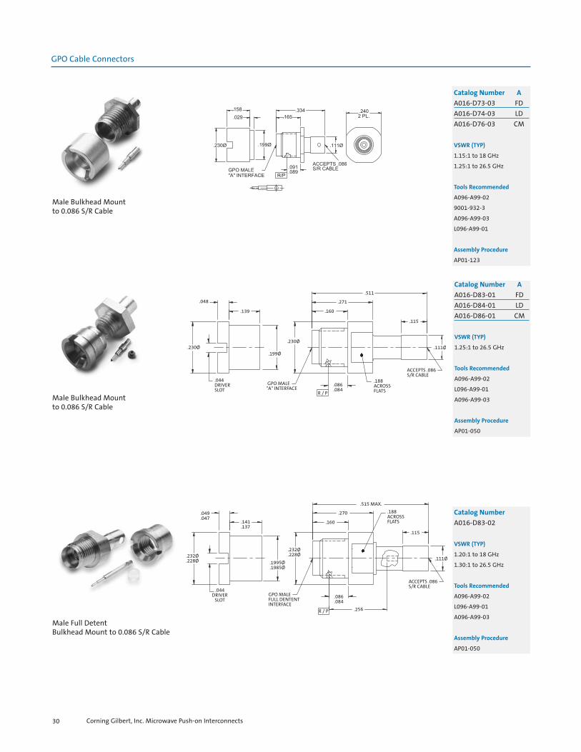
Male Bulkhead Mountto 0.086 S/R Cable
Catalog Number A
A016-D73-03 FDA016-D74-03 LDA016-D76-03 CM
VSWR (TYP)
1.15:1 to 18 GHz
1.25:1 to 26.5 GHz
Tools Recommended
A096-A99-02
9001-932-3
A096-A99-03
L096-A99-01
Assembly Procedure
AP01-123
Male Bulkhead Mountto 0.086 S/R Cable
.048
.139
.044DRIVERSLOT
.230Ø
GPO MALE"A" INTERFACE
.199Ø
.230Ø
.511
.271
.160
.188ACROSSFLATS
.115
ACCEPTS .086S/R CABLE
.111Ø
R / P
.086
.084
Catalog Number A
A016-D83-01 FDA016-D84-01 LDA016-D86-01 CM
VSWR (TYP)
1.25:1 to 26.5 GHz
Tools Recommended
A096-A99-02
L096-A99-01
A096-A99-03
Assembly Procedure
AP01-050
.049
.047.141.137
.044DRIVER
SLOT
.232Ø
.228Ø
GPO MALEFULL DENTENTINTERFACE
.1995Ø
.1985Ø
.232Ø
.228Ø
.515 MAX.
.270
.160
.188ACROSSFLATS
.115
ACCEPTS .086S/R CABLE
.111Ø
R / P .256
.086
.084
Male Full DetentBulkhead Mount to 0.086 S/R Cable
Catalog Number
A016-D83-02
VSWR (TYP)
1.20:1 to 18 GHz
1.30:1 to 26.5 GHz
Tools Recommended
A096-A99-02
L096-A99-01
A096-A99-03
Assembly Procedure
AP01-050
Corning Gilbert, Inc. Microwave Push-on Interconnects30

GPO Cable Connectors
Male Modified Smooth Bore Catchers MittBulkhead Mount to 0.086 S/R Cable
.141
.137
.049
.047
.232Ø
.228Ø.232Ø.228Ø
.1995Ø
.1985Ø
.044DRIVERSLOT
CATCHERS MITT
GPO MALEMODIFIEDSMOOTH BOREINTERFACE(.128Ø)
.086
.084
R/P
ACCEPTS .086S/R CABLE
.190
.186ACROSSFLATS
.524MAX
.115
.113Ø
.109Ø
.270
.160
Catalog Number
A016-D87-01
VSWR (TYP)
1.25:1 to 18 GHz
1.35:1 to 26.5 GHz
Tools Recommended
A096-A99-02
L096-A99-01
A096-A99-03
Assembly Procedure
AP01-050
Male Catchers Mitt Thread-on BulkheadMount to 0.086 S/R Cable
.044DRIVER
SLOT
.232Ø
.228Ø
.162
.158 .028
.1855Ø
.1835Ø
GPO MALECATCHERS MITTINTERFACE .015Ø
.042
.038 .195
.087Ø
.035
.113Ø
.147
.280
.092
.090
.250 HEX.
Catalog Number
0119-447-1
VSWR (TYP)
1.20:1 to 10 GHz
1.30:1 to 26.5 GHz
Tools Recommended
A096-A99-04
L096-A99-01
A096-A99-03
Assembly Procedure
AP01-056
Male Bulkhead Mount to RD-316 Cable
Catalog Number
A016-G86-01
VSWR (TYP)
1.15:1 to 3 GHz
Tools Recommended
A096-A99-04
L096-A99-01
A096-A99-03
Assembly Procedure
AP01-029
Corning Gilbert, Inc. Microwave Push-on Interconnects 31

GPO Cable Connectors
Male Bulkhead Mountto RG-178/196 Cable
Catalog Number A
A016-H83-01 FDA016-H84-01 LDA016-H85-01 SB
VSWR (TYP)
1.20:1 to 3 GHz
Tools Recommended
A096-A99-04
L096-A99-01
A096-A99-03
A018-B71-01
Assembly Procedure
IS-7095-5
BFOR
"C"
PANEL
A
D
DIELECTRIC STOP
.292Ø.131Ø
.292Ø .268Ø
ACCEPTS .047 S/R AND
.047 S/R MP CABLE
GPO FEMALE
INTERFACE
Female Snap-in Float Mount to0.047 and 0.047 S/R Microporous Cable
Catalog Number A B C D
A018-B71-01 .495 .221 .093 .234A018-B71-02 .530 .254 .150 .230
VSWR (TYP)
1.15:1 to 18 GHz
1.25:1 to 26.5 GHz
Tools Recommended
A096-A99-02
L096-A99-02
A096-A99-06
Assembly Procedure
IS-7582-1
Female Snap-in Float Mountto 0.086 S/R Cable
Catalog Number
A018-D11-01
VSWR (TYP)
1.15:1 to 15 GHz
1.30:1 to 26.5 GHz
Tools Recommended
A096-A99-02
L096-A99-01
A096-A99-06
Assembly Procedure
IS-7504-1
Corning Gilbert, Inc. Microwave Push-on Interconnects32

GPO Cable Connectors
Female Snap-in Float Mountto RG-316 Cable
Catalog Number
A018-F71-01
VSWR (TYP)
1.15:1 to 3 GHz
Tools Recommended
A096-A99-02
L096-A99-01
A096-A99-06
Assembly Procedure
AP01-049
Female Straight Float MountSnap-in to RG-178 Cable
.292Ø.132Ø
GPO CONTACT
GPO FEMALEINTERFACE
.499
.222.268Ø
FOR .093PANEL ASSHOWN
.292Ø
ACCEPTSRG-178CABLE
DIELECTRIC STOP
.234
Catalog Number
0119-392-3
VSWR (TYP)
1.15:1 to 4 GHz
Tools Recommended
A096-A99-02
L096-A99-01
A096-A99-06
Assembly Procedure
AP01-078
Female Straight Float MountSnap-in to 421-042 Flex Cable
GPO MALE.220 [5.6]
.131Ø[3.3].292Ø [7.4]
.234 [5.9]
.202 [5.1]
.185 [4.7]
.155 [3.9]
.075 [1.9]
.040Ø THRU ONE WALL
.050Ø [1.3]
.070Ø [1.8]
.080Ø[2.0]
.118Ø[3.0]
.292Ø[7.4]
Catalog Number
0119-533-3
VSWR (TYP)
1.15:1 to 12 GHz
1.20:1 to 26 GHz
Tools Recommended
A096-A99-02
L096-A99-02
A096-A99-06
Assembly Procedure
IS-7856-1
Corning Gilbert, Inc. Microwave Push-on Interconnects 33

GPO Cable Connectors
GPO Loads
Male Catchers Mitt Bulkhead FloatMount to 0.141 Microporous S/R Cable
.197
.095
.280Ø
GPO MALECATCHERS MITTINTERFACE
1/4 HEXACCEPTS .141MICROPOROUSS/R CABLE
.170Ø
.066
.484
.274
Catalog Number
0119-590-3
Tools Recommended
A096-A99-02
L096-A99-01
A096-A99-09
Assembly Procedure
AP01-045
Female 50 Ohm Load
Catalog Number Grade
A055-A11-01 TEST GRADEA055-A11-02 FIELD GRADE
VSWR (TYP)
TEST GRADE 1.20:1 to 26.5 GHz
FIELD GRADE 1.25:1 to 26.5 GHz
Male 50 Ohm Load
Catalog Number A Grade
A055-A14-01 LD TEST GRADEA055-A15-01 SB TEST GRADEA055-A14-02 LD FIELD GRADEA055-A15-02 SB FIELD GRADE
VSWR (TYP)
TEST GRADE 1.20:1 to 18 GHz, 1.40:1 to 26.5 GHz
FIELD GRADE 1.30:1 to 18 GHz, 1.50:1 to 26.5 GHz
Corning Gilbert, Inc. Microwave Push-on Interconnects34

GPO Hermetic Seals
GPO Blindmate Interconnects
50 Ohm Hermetic Seal
Catalog Number A
Y007-L42-03 .050Y007-L42-02 .125Y007-L42-04 .200
VSWR (TYP)
1.15:1 to 26.5 GHz
Female Blindmate Interconnect
Catalog Number A B
A1A1-0001-01 .254 .114A1A1-0001-03 .395 .254
* Note: Bullets of almost any lengthcan be created to suit your application. Please contact customer service forfurther information.
VSWR (TYP)1.10:1 to 8 GHz1.35:1 to 26.5 GHz
Female Blindmate Interconnect
Catalog Number
A1A1-0001-02
VSWR (TYP)
1.10:1 to 12 GHz
1.40:1 to 26.5 GHz
Corning Gilbert, Inc. Microwave Push-on Interconnects 35

GPO Blindmate Interconnects
Female Blindmate InterconnectSelf-Adjusting
GPO FEMALEINTERFACE(4 SLOT)
GPO FEMALEINTERFACE(6 SLOT)
.132Ø .132Ø
.675(COMPRESS TO .600 MIN.)
.136
.114 O-RING .114
Catalog Number
A1A1-0001-09
VSWR (TYP)
1.20:1 to 8 GHz
1.40:1 to 26.5 GHz
Spring Loaded Bullet
Catalog Number
A1A1-0001-34
Female Blindmate Interconnect
GPO FEMALEINTERFACE2 PL.
.135Ø
.129Ø2 PL.
.2252 PL.
.134Ø
.853
.849
.401 Catalog Number
A1A1-0001-15
VSWR (TYP)
1.50:1 to 26.5 GHz
Corning Gilbert, Inc. Microwave Push-on Interconnects36
GPO Blindmate Interconnects
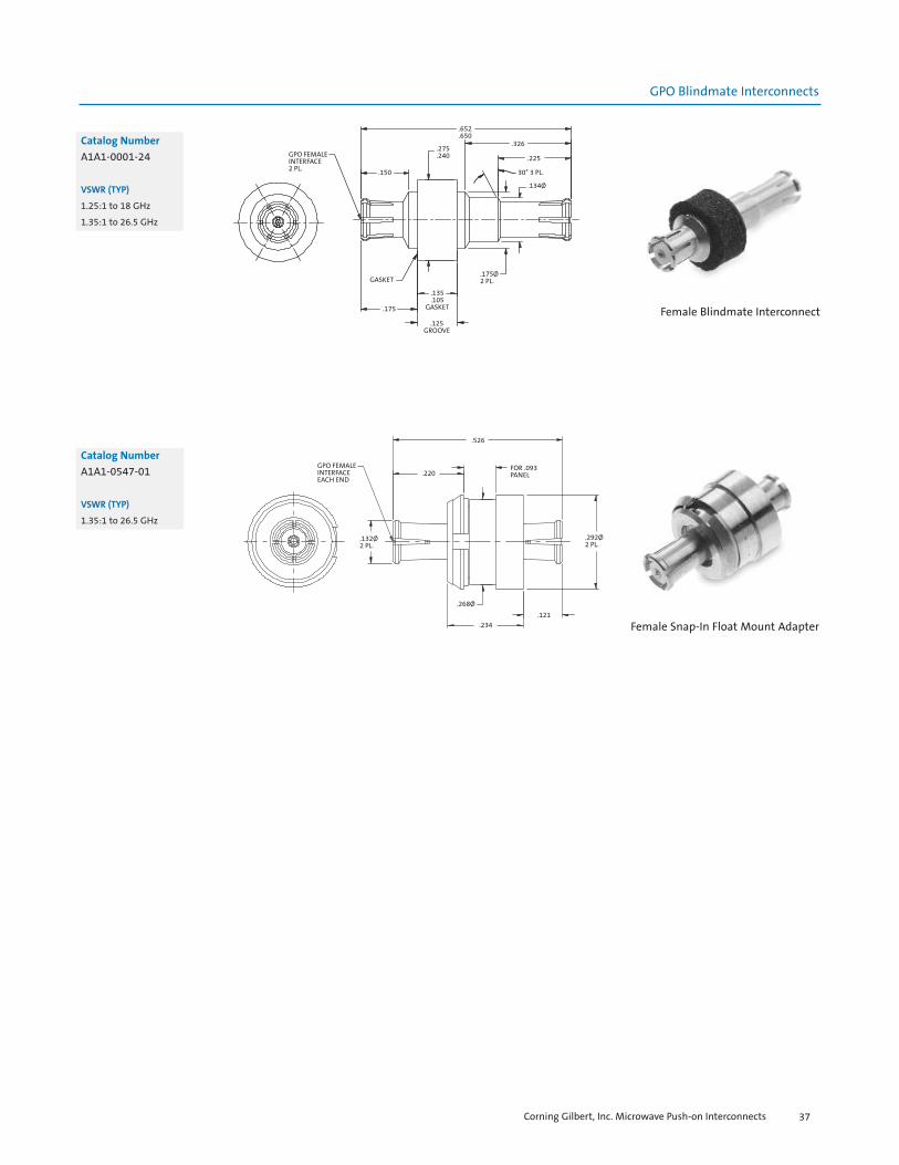
Female Blindmate Interconnect
GPO FEMALEINTERFACE2 PL. .150
.275
.240
.652
.650.326
.225
30° 3 PL.
.134Ø
.175Ø2 PL.
.135
.105GASKET
.125GROOVE
.175
GASKET
Catalog Number
A1A1-0001-24
VSWR (TYP)
1.25:1 to 18 GHz
1.35:1 to 26.5 GHz
Female Snap-In Float Mount Adapter
GPO FEMALEINTERFACEEACH END
.132Ø2 PL.
.526
.220FOR .093PANEL
.292Ø2 PL.
.121.234
.268Ø
Catalog Number
A1A1-0547-01
VSWR (TYP)
1.35:1 to 26.5 GHz
Corning Gilbert, Inc. Microwave Push-on Interconnects 37
GPO Pins
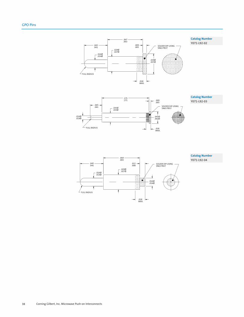
.045
.041
.067
.063
.009
.005
.016Ø
.014Ø
.029Ø
.027Ø
FULL RADIUS
.018MAX.
.039Ø
.037Ø
SOLDER DIP USINGSN63 PB37
Catalog Number
Y071-L92-02
Catalog Number
Y071-L92-03
Catalog Number
Y071-L92-04
.045
.041
.175
.171 .009.005
.016Ø
.014Ø
.035Ø
.033Ø
FULL RADIUS .018MAX.
.045Ø
.043Ø
SOLDER DIP USINGSN63 PB37
.045
.041
.069
.065
.012
.008
.016Ø
.014Ø
.029Ø
.027Ø
FULL RADIUS
.018MAX.
.016Ø
.014Ø
SOLDER DIP USINGSN63 PB37
Corning Gilbert, Inc. Microwave Push-on Interconnects38


General Characteristics
Impedance Frequency rangeTemperature range
Electrical Characteristics
VSWRInsertion lossDWV@ Sea Level:Insulation resistanceContact resistance
Outer conductorInner conductor
RF leakage
Mechanical Characteristics
Mate/Demate CyclesForce to engage/disengageTolerated misalignment
RadialAxial
Environmental Characteristics
Thermal ShockSalt SprayVibrationShockMoisture resistance
Materials (typical)
BodiesOuter contactsCenter contactsInsulatorsSprings
Finish (typical)
Bodies
Contacts
*Note: Corning Gilbert male connectors have a full self-centering mechanism
50 ohms nominalDC to 65 GHz-55oC thru 165oC
1.10:1 to 26.5 GHz typical; 1.30 : 1 typical to 50 GHz.12 f GHz325 Vrms5,000 megohms min.
2 milliohms max.6 milliohms max.-80 dB (typical mated pair)
Full Detent - 100min.; Smooth Bore - 500min.FD - 4.5lbs.typ./7.0lbs.typ.; SB - 2.5lbs.typ./1.5lbs.typ.
+/- 0.010”0.010” (flush to 0.010” from the reference plane)
MIL-STD-202, Method 107, Condition BMIL-STD-202, Method 101MIL-STD-202, Method 204MIL-STD-202, Method 213, Condition IMIL-STD-202, Method 106, except Step 7B
Beryllium Copper per ASTM B196 and or/ASTM B197Beryllium Copper per ASTM B196 and or/ASTM B197Beryllium Copper per ASTM B196 and or/ASTM B197PTFE Fluorocarbon per ASTM D1710 and ASTM D 145717-7 Stainless Steel per ASTM A313-95A
Gold plated per MIL-G-45204, Type I, Grade C, Class 1,Over Nickel Plate per QQ-N-290Gold plated per MIL-G-45204, Type I, Grade C, Class 1,Over Nickel Plate per QQ-N-290
Corning Gilbert, Inc. Microwave Push-on Interconnects40
GPPO Specifications

GPPO Flange Mounts
Male Flange MountShroud No Center Conductor
Catalog Number A B Cø D Eø
B001-A23-01 FD .282 .375 .125 .073B001-A25-01 SB .282 .375 .125 .073B001-A23-02 FD .481 .625 .150 .103B001-A25-02 SB .481 .625 .150 .103
Tools Recommended
B090-A99-08 (for - 02 series)
B090-A99-09 (for - 01 series)
B090-A99-01
Male Flange Mount Shroud Accepts 0.009 Center Conductor
Catalog Number A
B001-N33-01 FDB001-N35-01 SB
VSWR (TYP)
1.25:1 to 26.5 GHz
1.35:1 to 40 GHz
Male Thread-in Shroud No C/C
.091
.009
.007
R / P
GPPO MALE "A" INTERFACE
.140ØMAX.
.164-64 UNS-2A THD.
Catalog Number A
B003-A23-01 FDB003-A25-01 SB
Tools Recommended
B090-A99-05
B097-A99-01 for FD
B097-A99-02 for SB
Assembly Procedure
AP01-101
Corning Gilbert, Inc. Microwave Push-on Interconnects 41
GPPO Thread-In Shrouds
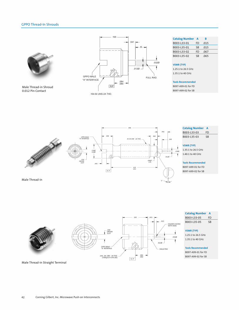
GPPO Thread-In Shrouds
Catalog Number A B
B003-L33-01 FD .015B003-L35-01 SB .015B003-L33-02 FD .067B003-L35-02 SB .065
VSWR (TYP)
1.25:1 to 26.5 GHz
1.35:1 to 40 GHz
Tools Recommended
B097-A99-01 for FD
B097-A99-02 for SBMale Thread-in Shroud0.012 Pin Contact
GPPO MALE"A" INTERFACE
.098
.030DRIVER
SLOT .043
R / P
.126Ø
.124Ø
#5-44 UNF - 2A THD.
.496
.060
.092
.040
.415
.411
.096Ø2 PL.
.038Ø
.012Ø
5°
Catalog Number A
B003-L33-03 FDB003-L35-03 SB
VSWR (TYP)
1.35:1 to 26.5 GHz
1.40:1 to 40 GHz
Tools Recommended
B097-A99-01 for FD
B097-A99-02 for SB
Male Thread-in
.030DRIVERSLOT
GPPO MALE"A" INTERFACE
.164 - 64 UNS - 2A THD.(TORQUE 4-6 IN-LBS)
R / P
.084
.080
.165 .041
.015
SOLDER COATEDWITH SN36
.012Ø
DIELECTRIC
.032Ø
Catalog Number A
B003-L33-05 FDB003-L35-05 SB
VSWR (TYP)
1.25:1 to 26.5 GHz
1.35:1 to 40 GHz
Tools Recommended
B097-A99-01 for FD
B097-A99-02 for SB
Male Thread-in Straight Terminal
Corning Gilbert, Inc. Microwave Push-on Interconnects42

GPPO Thread-In Shrouds
Male Thread-in Straight Terminal
.030DRIVERSLOT
GPPO MALE"A" INTERFACE
.164 - 64 UNS - 2A THD.(TORQUE 4-6 IN-LBS)
R / P
.084
.080
.165 .058.054
.041SOLDER COATEDPER MPS-156
DIELECTRIC
.012Ø
.032Ø
Catalog Number A
B003-L33-06 FDB003-L35-06 SB
VSWR (TYP)
1.25:1 to 26.5 GHz
1.35:1 to 40 GHz
Tools Recommended
B097-A99-01 for FD
B097-A99-02 for SB
Male Thread-in Shroud2.92mm Sparkplug
Catalog Number A
B003-N33-01 FDB003-N35-01 SB
VSWR (TYP)
1.25:1 to 26.5 GHz
1.35:1 to 40 GHz
Tools Recommended
A090-A99-07
B097-A99-01 for FD
B097-A99-02 for SB
Assembly Procedure
AP01-104
Male Thread-in Shroud1.85mm Sparkplug
Catalog Number A
B003-N33-02 FDB003-N35-02 SB
VSWR (TYP)
1.25:1 to 26.5 GHz
1.35:1 to 40 GHz
Tools Recommended
B097-A99-01 for FD
B097-A99-02 for SB
Corning Gilbert, Inc. Microwave Push-on Interconnects 43

GPPO Thread-In Shrouds
GPPO MALE"A" INTERFACE
.040
.040DRIVER
SLOT
.119Ø
.044
.042
.155Ø
(.201)
.050RAD.
.120
.161
.155
#6 - 80 SPECIAL THD.MAJOR DIA: .1372 - .1340PITCH DIA: .1273 - .1291MINOR DIA: .1219 MAX
.157
.016Ø
.014Ø.080
MIN WHENINSTALLED
FLOATING .014Ø - .016Ø PIN(MAX. DISENGAGEMENT .050)
Catalog Number A
B024-L33-01 FDB024-L35-01 SB
VSWR (TYP)
1.25:1 to 26.5 GHz
1.35:1 to 40 GHz
Tools Recommended
B097-A99-01 for FD
B097-A99-02 for SB
Male Thread-in to Stripline Launchwith 0.0150 Pin
GPPO MALE"A" INTERFACE
.040DRIVER
SLOT
.499
.493
#5-44 UNF - 2A
.098
.125Ø
.030
R / P
.417
.409
.096Ø2 PL.
.060
.092 *
.091Ø
Catalog Number A
B024-L33-02 FDB024-L35-02 SB
VSWR (TYP)
1.35:1 to 26.5 GHz
1.40:1 to 40 GHz
Tools Recommended
B097-A99-01 for FD
B097-A99-02 for SB
Male Thread-in
.143
.009SLOTS
.012
.009
.126Ø
.124Ø
GPPO MALEFULL DETENTINTERFACE
R / P
.013Ø
.011Ø
.100Ø
.079Ø
.077Ø
.010C'BORE
.062
.058
.040
.020SLOT4 PL.
Catalog Number
B007-L43-03
VSWR (TYP)
1.25:1 to 26.5 GHz
1.35:1 to 40 GHz
Male Full Detent High Power63 Ohm Hermetic Shroud Solder in
Corning Gilbert, Inc. Microwave Push-on Interconnects44
GPPO Hermetic Shrouds

GPPO Hermetic Shrouds
Male Smooth Bore High Power63 Ohm Hermetic Shroud Solder In
GPPO MALESMOOTH BOREINTERFACE
R / P
.010C'BORE
.040
.062
.058
.126Ø
.124Ø
.143
.017
.013Ø
.011Ø.079Ø.077Ø .100Ø
Catalog Number
B007-L45-01
Male Smooth Bore High Power63 Ohm Hermetic Shroud Solder In
with Tin Dip
.143
.047
.007
.126Ø
.124Ø
GPPO MALESMOOTH BOREINTERFACE
R / P
.062
.058
.040
.010C'BORE
.017
.013Ø
.011Ø
SOLDER DIPUSINGSN63 PB37
.079Ø
.077Ø .100Ø
Catalog Number
B007-L45-01-T
Male Smooth Bore High Power63 Ohm Hermetic Shroud Solder In
.126Ø
.124Ø
.143
.015
.009
.012Ø
.100Ø
GPPO MALESMOOTH BOREINTERFACE .043
.035
R / P
.061
.059
.040
.010C'BORE
Catalog Number
B007-L45-06
TAB = “L” x 103 inches
Corning Gilbert, Inc. Microwave Push-on Interconnects 45
GPPO Hermetic Shrouds
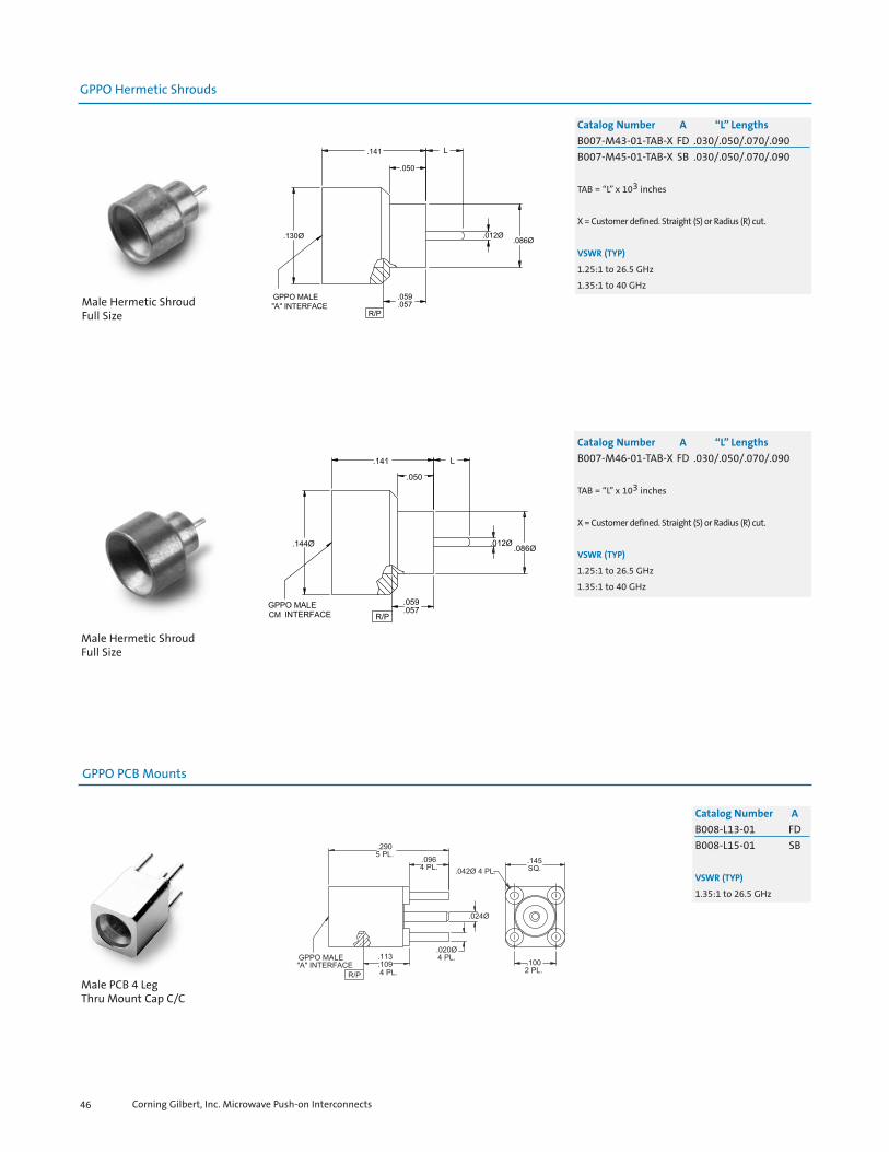
Catalog Number A “L” Lengths
B007-M43-01-TAB-X FD .030/.050/.070/.090B007-M45-01-TAB-X SB .030/.050/.070/.090
TAB = “L” x 103 inches
X = Customer defined. Straight (S) or Radius (R) cut.
VSWR (TYP)
1.25:1 to 26.5 GHz
1.35:1 to 40 GHz
Male Hermetic ShroudFull Size
Catalog Number A “L” Lengths
B007-M46-01-TAB-X FD .030/.050/.070/.090
TAB = “L” x 103 inches
X = Customer defined. Straight (S) or Radius (R) cut.
VSWR (TYP)
1.25:1 to 26.5 GHz
1.35:1 to 40 GHz
Male Hermetic ShroudFull Size
Catalog Number A
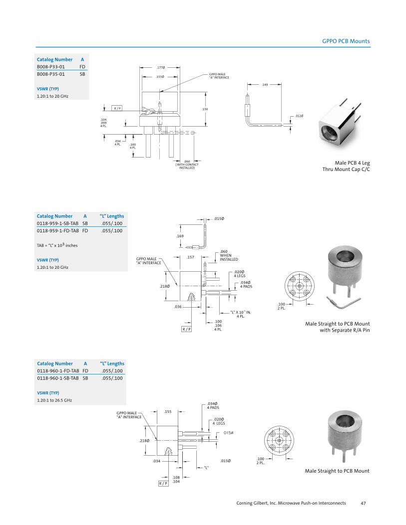
B008-L13-01 FDB008-L15-01 SB
VSWR (TYP)
1.35:1 to 26.5 GHz
Male PCB 4 Leg Thru Mount Cap C/C
Corning Gilbert, Inc. Microwave Push-on Interconnects46
GPPO PCB Mounts
GPPO PCB Mounts
Male PCB 4 Leg Thru Mount Cap C/C
R / P
.104
.0994 PL.
.0344 PL. .100
4 PL.
.177Ø
.155Ø
.060( WITH CONTACT
INSTALLED)
GPPO MALE"A" INTERFACE
.149
.150
.012Ø
Catalog Number A
B008-P33-01 FDB008-P35-01 SB
VSWR (TYP)
1.20:1 to 20 GHz
Male Straight to PCB Mountwith Separate R/A Pin
.1002 PL.
GPPO MALE"A" INTERFACE
.218Ø
.036
R / P
.100
.1064 PL.
"L" X 10-3 IN.4 PL.
.015Ø
.169
.157.060WHENINSTALLED
.020Ø4 LEGS
.034Ø4 PADS
Catalog Number A “L” Lengths
0118-959-1-SB-TAB SB .055/.1000118-959-1-FD-TAB FD .055/.100
TAB = “L” x 103 inches
VSWR (TYP)
1.20:1 to 20 GHz
GPPO MALE"A" INTERFACE
.155
.218Ø
.034
R / P
.108
.104
"L"
.1002 PL..015Ø
.020Ø4 LEGS
.034Ø4 PADS
Catalog Number A “L” Lengths
0118-960-1-FD-TAB FD .055/.1000118-960-1-SB-TAB SB .055/.100
VSWR (TYP)
1.20:1 to 26.5 GHz
Male Straight to PCB Mount
Corning Gilbert, Inc. Microwave Push-on Interconnects 47

GPPO PCB Mounts
Male R/A PCB 4 Leg Thru Mount Cap C/C
Catalog Number A
B009-P33-01 FDB009-P35-01 SB
VSWR (TYP)
1.40:1 to 26.5 GHz
Male R/A PCB Mount0.135 Legs
GPPO MALE"A" INTERFACE
.020Ø4 PL.
.024Ø
.135Ø
.1002 PL.
.042Ø4 PL.
.145.1355 PL.
.290 .134.130
R / P
.0884 PL.
Catalog Number A
B009-P33-02 FDB009-P35-02 SB
VSWR (TYP)
1.40:1 to 26.5 GHz
Male PCB Edge Mount
Catalog Number A
B010-L13-01 FDB010-L15-01 SB
VSWR (TYP)
1.25:1 to 26.5 GHz
Corning Gilbert, Inc. Microwave Push-on Interconnects48
GPPO Edge Mounts

GPPO Edge Mounts
.045
.0412 PL.
.122
.118
.081
.0792 PL.
.165 .0563 PL.
GPPO MALE"A" INTERFACE R / P
.085
.079
.0122 PL.
.012Ø
.031
.157Ø
.031
.125
.0562 PL.
.120
.0072 PL.
Catalog Number A
B010-L13-02 FDB010-L15-02 SB
VSWR (TYP)
1.25:1 to 26.5 GHz
Male PCB Edge Launch
.134MAX.2 PL.
GPPO MALE"A" INTERFACE R / P
ACCESS CONTACT
.346.100
.165
.161.143
.080
.0113Ø
.028
.026
.018
.016
Catalog Number A
B010-L33-03 FDB010-L35-03 SB
VSWR (TYP)
1.25:1 to 26.5 GHz
Male Edge Mountwith Separate Pin
Corning Gilbert, Inc. Microwave Push-on Interconnects 49
.346.005 .100
2 PL.
.134ØMAX.2 PL.
GPPO MALE"A" INTERFACE
R / P
.165
.161
.012Ø
.143
ACCESS CONTACT
.006
.016.016
.031
.029
.031
.029
Catalog Number A
B010-L33-04 FDB010-L35-04 SB
VSWR (TYP)
1.25:1 to 26.5 GHz

GPPO Edge Mounts
Male PCB Edge Mount
R / P
.143Ø
GPPO MALE"A" INTERFACE
.220
.187
.118
.019Ø
.0122 PL.
.103Ø
Catalog Number A
B010-L83-01 FDB010-L85-01 SB
Catalog Number A
B010-L83-02 FDB010-L85-02 SB
VSWR (TYP)
1.25:1 to 26.5 GHz
Corning Gilbert, Inc. Microwave Push-on Interconnects50
GPPO Surface Mounts
Corning Gilbert, Inc. Microwave Push-on Interconnects 51
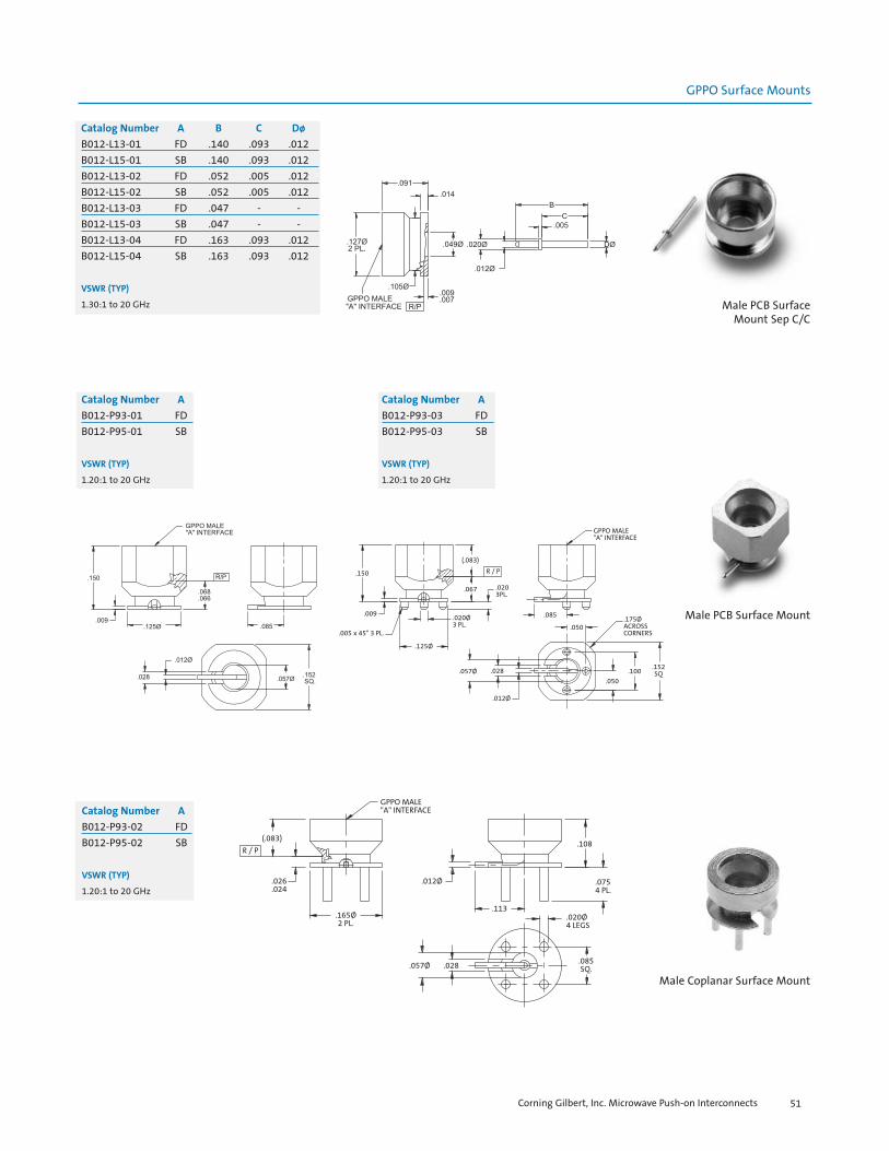
Male PCB SurfaceMount Sep C/C
Catalog Number A B C Dø
B012-L13-01 FD .140 .093 .012B012-L15-01 SB .140 .093 .012B012-L13-02 FD .052 .005 .012B012-L15-02 SB .052 .005 .012B012-L13-03 FD .047 - - B012-L15-03 SB .047 - - B012-L13-04 FD .163 .093 .012B012-L15-04 SB .163 .093 .012
VSWR (TYP)
1.30:1 to 20 GHz
Male PCB Surface Mount
GPPO MALE"A" INTERFACE
(.083)
R / P
.026
.024
.165Ø2 PL.
.012Ø
.113
.057Ø .028
.020Ø4 LEGS
.0754 PL.
.108
.085SQ.
Catalog Number A
B012-P93-02 FDB012-P95-02 SB
VSWR (TYP)
1.20:1 to 20 GHz
Male Coplanar Surface Mount
.150
.009
.005 x 45° 3 PL.
.125Ø
.020Ø3 PL.
(.083)
R / P
.067 .0203PL.
.085
.050
.057Ø .028
.012Ø
.175ØACROSSCORNERS
.050.100
.152SQ
GPPO MALE"A" INTERFACE
Catalog Number A
B012-P93-01 FDB012-P95-01 SB
VSWR (TYP)
1.20:1 to 20 GHz
Catalog Number A
B012-P93-03 FDB012-P95-03 SB
VSWR (TYP)
1.20:1 to 20 GHz

GPPO Surface Mounts
Male R/A Surface Mount
.200ØACROSSCORNERS
.156
.078
.078
.151
.226
.100
SOLDER DIPPER MPS-160
.078
.146Ø
GPPO MALE"A" INTERFACE
R / P.143
.012Ø
.060Ø
(.030)
Catalog Number A
B013-L93-01 FDB013-L95-01 LD
VSWR (TYP)
1.20:1 to 20 GHz
Female Straightto 0.047 S/R Cable
Female Straightto 0.086 S/R Cable
Catalog Number
B014-D11-01
VSWR (TYP)
1.15:1 to 26.5 GHz
1.30:1 to 40 GHZ
Tools Recommended
B096-A93-01
A096-A99-04
L096-A99-01
Assembly Procedure
AP01-148
GPPO Cable Connectors
Corning Gilbert, Inc. Microwave Push-on Interconnects52
Catalog Number
B014-B11-01
VSWR (TYP)
1.15:1 to 26.5 GHz
1.25:1 to 40 GHZ
Tools Recommended
B096-A93-01
A096-A99-04
L096-A99-02
Assembly Procedure
AP01-133

GPPO Cable Connectors
GPPO FEMALEINTERFACE
.091Ø
R / P
.265
.124Ø
.094Ø
.202
Catalog Number
B014-K11-01
Tools Recommended
B096-A93-01
A096-A99-04
L096-A99-01
Assembly Procedure
AP01-108 Female Straightto M1049 (0.080) Flex Cable
GPPO FEMALEINTERFACE
.091Ø
.700
.298
.266
R / P
.501
HOUSING
.128Ø
ACCEPTS STORM421-1006-001CABLE
CABLE STOP
Catalog Number
0118-968-3
Tools Recommended
B096-A93-01
A096-A99-04
L096-A99-01
Assembly Procedure
AP01-143
Female to421-1006-001 Cable
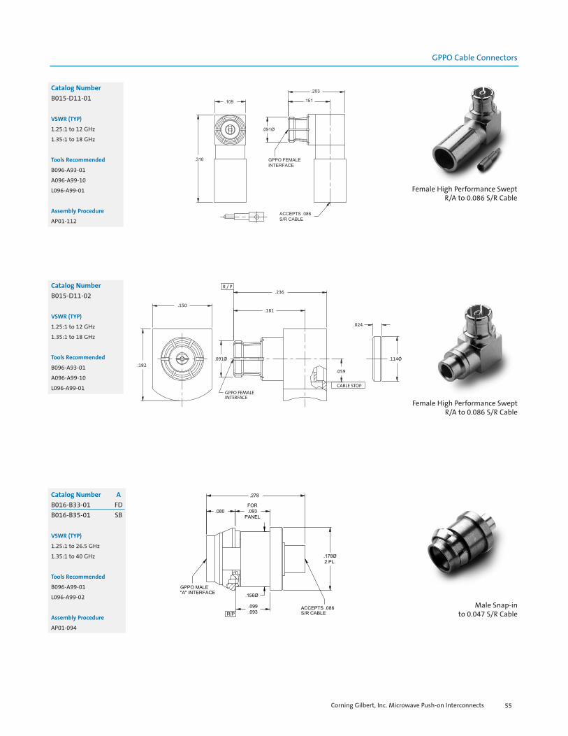
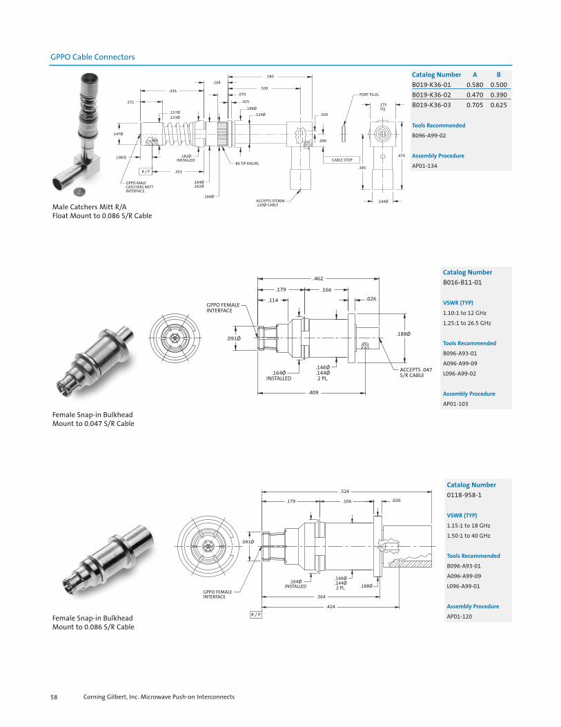
Catalog Number
B015-B11-01
VSWR
1.20:1 to 10 GHz
1.30:1 to 20 GHz
Tools Recommended
B096-A93-01
L096-A99-02
A096-A99-09
Assembly Procedure
AP01-080 Female R/Ato 0.047 S/R Cable
Corning Gilbert, Inc. Microwave Push-on Interconnects 53

GPPO Cable Connectors
Female High Performance SweptR/A to 0.047 S/R Cable
Catalog Number
B015-B11-02
VSWR
1.25:1 to 18 GHz
1.35:1 to 26.5 GHz
Tools Recommended
B096-A93-01
A096-A99-10
L096-A99-02
Assembly Procedure
AP01-076
Female R/Ato 0.047 S/R Cable
.109
.400
.361
.109Ø
GPPO FEMALEINTERFACE
.091Ø.149
PORT PLUG
.045
CABLE STOP
ACCEPTS .047S/R CABLE
Catalog Number
B015-B11-04
VSWR
1.10:1 to 5 GHz
1.30:1 to 10 GHz
Tools Recommended
B096-A93-01
A096-A99-09
L096-A99-02
Assembly Procedure
AP01-150
Female R/Ato 0.047 S/R Cable
.137
.137
.267.153
CABLE STOP
.076Ø
GPPO FEMALEINTERFACE
.091Ø
.229
.170
ACCEPTS .047 S/R CABLE
.093
Catalog Number
0118-927-1
VSWR
1.20:1 to 18 GHz
1.30:1 to 26.5 GHz
Tools Recommended
B096-A93-01
A096-A99-10
L096-A99-02
Assembly Procedure
AP01-122
Corning Gilbert, Inc. Microwave Push-on Interconnects54
GPPO Cable Connectors
Catalog Number
B015-D11-01
VSWR (TYP)
1.25:1 to 12 GHz
1.35:1 to 18 GHz
Tools Recommended
B096-A93-01
A096-A99-10
L096-A99-01
Assembly Procedure
AP01-112
Female High Performance SweptR/A to 0.086 S/R Cable
R / P
.150
.182
.236
.181
.091Ø
GPPO FEMALEINTERFACE
CABLE STOP
.059
.024
.114Ø
Catalog Number
B015-D11-02
VSWR (TYP)
1.25:1 to 12 GHz
1.35:1 to 18 GHz
Tools Recommended
B096-A93-01
A096-A99-10
L096-A99-01
Female High Performance SweptR/A to 0.086 S/R Cable
Catalog Number A
B016-B33-01 FDB016-B35-01 SB
VSWR (TYP)
1.25:1 to 26.5 GHz
1.35:1 to 40 GHz
Tools Recommended
B096-A99-01
L096-A99-02
Assembly Procedure
AP01-094
Male Snap-into 0.047 S/R Cable
Corning Gilbert, Inc. Microwave Push-on Interconnects 55

GPPO Cable Connectors
Male Bulkhead Mount to 0.047 S/R Cable
Female Snap-In BulkheadMount to 0.047 S/R Cable
GPPO MALE"A" INTERFACE
.044
.125PANEL
.132Ø2 PL.
.030DRIVER
SLOT.030
R / P
.087
.085 .125ACROSS
FLATS
.142Ø
ACCEPTS .047S/R CABLE
.077Ø.094Ø
.150Ø
.038 .071
.013
Catalog Number A
B016-B33-02 FDB016-B35-02 SB
VSWR (TYP)
1.25:1 to 26.5 GHz
1.35:1 to 40 GHz
Tools Recommended
B096-A99-01
L096-A99-02
Assembly Procedure
AP01-110
GPPO FEMALEINTERFACE
.146Ø
.144Ø2 PL.
.091Ø
.114
.185
.470
.168
.026
.164ØINSTALLED
.372
.417
.188Ø
ACCEPTS .047S/R CABLE
Catalog Number
0118-961-4
VSWR (TYP)
1.10:1 to 12 GHz
1.25:1 to 26.5 GHz
Tools Recommended
B096-A93-01
A096-A99-09
L096-A99-02
Assembly Procedure
AP01-103
Male Snap-into 0.047 S/R Cable
.302
FOR.093
PANEL.080
.146Ø.130Ø
GPPO MALE"A" INTERFACE
.003
R / P
.156Ø
.135TO PANEL
.178Ø2 PL.
ACCEPTS .086S/R CABLE
Catalog Number A
B016-D33-01 FDB016-D35-01 SB
VSWR (TYP)
1.25:1 to 26.5 GHz
1.35:1 to 40 GHz
Tools Recommended
B096-A99-01
L096-A99-01
Assembly Procedure
AP01-092
Corning Gilbert, Inc. Microwave Push-on Interconnects56

GPPO Cable Connectors
GPPO MALE"A" INTERFACE
.044
.142Ø
.030DRIVER
SLOT
.125PANEL
.038 .096
.132Ø2 PL.
R / P
.087
.085 .125ACROSS
FLATS
ACCEPTS .086S/R CABLE
.030
.115Ø
.150Ø
Catalog Number A
B016-D33-02 FDB016-D35-02 SB
VSWR (TYP)
1.25:1 to 26.5 GHz
1.35:1 to 40 GHz
Tools Recommended
B096-A99-01
L096-A99-01
Assembly Procedure
AP01-111
Male Snap-into 0.086 S/R Cable
(.751)
.436
80 TPI KNURL.151
.157Ø
.153Ø
.147Ø
GPPO MALECATCHERS MITTINTERFACE
.589
R / P
.083
.182ØINSTALLED
.164Ø
.162Ø
.168Ø
.168 .122
.188Ø
.025
.070
.124Ø
ACCEPTS .086S/R CABLE
Catalog Number
0118-928-4-CM
VSWR (TYP)
1.18:1 to 18 GHz
1.35:1 to 30 GHz
Tools Recommended
B096-A99-02
L096-A99-01
Assembly Procedure
AP01-090
Male Catchers MittSnap-in Float Mount to 0.086 S/R Cable
.436
.151
.157Ø
.153Ø
.147Ø
(.083)
R / P
GPPO MALECATCHERS MITTINTERFACE
.353
.182ØINSTALLED
.164Ø
.162Ø
.168Ø
.124Ø
80 TPI KNURL
ACCEPTS .086S/R CABLE
CABLE STOP
.168.318
.238.070
.025.188Ø .020Ø
.090
PORT PLUG
.040 X 45°2 PL.
.020 X 45°2 PL.
.120Ø
.175SQ.
.270.185
Catalog Number
B019-D36-01
Tools Recommended
B096-A99-02
Assembly Procedure
AP01-145
Male Catchers Mitt R/AFloat Mount to 0.086 S/R Cable
Corning Gilbert, Inc. Microwave Push-on Interconnects 57
GPPO Cable Connectors
Male Catchers Mitt R/AFloat Mount to 0.086 S/R Cable
.436
.151
.157Ø
.153Ø
.147Ø
(.083)
R / P
GPPO MALECATCHERS MITTINTERFACE
.353
.182ØINSTALLED
.164Ø
.162Ø
.168Ø
80 TIP KNURL
ACCEPTS STORM.120Ø CABLE
.168
.580
.500
.070
.025
.188Ø
.124Ø .020
.090
CABLE STOP
.385
PORT PLUG
.175SQ.
.470
.144Ø
Catalog Number A B
B019-K36-01 0.580 0.500B019-K36-02 0.470 0.390B019-K36-03 0.705 0.625
Tools Recommended
B096-A99-02
Assembly Procedure
AP01-134
Female Snap-in BulkheadMount to 0.047 S/R Cable
GPPO FEMALEINTERFACE
.091Ø
.114
.179
.462
.166
.164ØINSTALLED
.409
.146Ø
.144Ø2 PL.
.026
.188Ø
ACCEPTS .047S/R CABLE
Catalog Number
B016-B11-01
VSWR (TYP)
1.10:1 to 12 GHz
1.25:1 to 26.5 GHz
Tools Recommended
B096-A93-01
A096-A99-09
L096-A99-02
Assembly Procedure
AP01-103
Female Snap-in BulkheadMount to 0.086 S/R Cable
.091Ø
GPPO FEMALEINTERFACE
R / P
.164ØINSTALLED
.146Ø
.144Ø2 PL.
.364
.424
.188Ø
.179
.524
.166 .026
Catalog Number
0118-958-1
VSWR (TYP)
1.15:1 to 18 GHz
1.50:1 to 40 GHz
Tools Recommended
B096-A93-01
A096-A99-09
L096-A99-01
Assembly Procedure
AP01-120
Corning Gilbert, Inc. Microwave Push-on Interconnects58

GPPO Cable Connectors
.091Ø
GPPO FEMALEINTERFACE
R / P
.532
.168.185
.114
.026.188Ø
.164ØINSTALLED
.372
.432
.146Ø
.144Ø2 PL.
Catalog Number
0118-958-4
VSWR (TYP)
1.15:1 to 18 GHz
1.50:1 to 40 GHz
Tools Recommended
B096-A93-01
A096-A99-09
L096-A99-02
Assembly Procedure
AP01-142
Female Snap-in Bulkhead Mountto 0.086 S/R Cable
.480Ø
.328
.165
C'SINK .140Ø x 82°.073Ø THRU 2 PL.
GPPO MALE"A" INTERFACE
.084
.082 R / P
.207
.380
.100
.112Ø2 PL.
CENTER CONTACT
ACCEPTS .086S/R CABLE
Catalog Number A
B001-D33-01 FDB001-D35-01 SB
VSWR (TYP)
1.30:1 to 40 GHz
Assembly Procedure
AP01-119
Male 2 Hole Flange Mountto 0.086 S/R Cable
Male Flange Mountto 0.116 S/R Cable
.480Ø
.328
.165
#2 56 UNC-2B 2 PL.
.045.171
.388
GPPO MALE"A" INTERFACE
R / P
.084
.082
.191
.144Ø .164Ø
ACCEPTS .116S/R CABLE
CENTERCONTACT
DIELECTRIC
Catalog Number A
B001-K33-01 FDB001-K35-01 SB
Tools Recommended
B096-A99-01
L096-A99-03
L096-A99-01
Assembly Procedure
AP01-106
Corning Gilbert, Inc. Microwave Push-on Interconnects 59
GPPO Loads
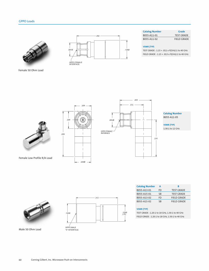
Female 50 Ohm Load
Catalog Number Grade
B055-A11-01 TEST GRADEB055-A11-02 FIELD GRADE
VSWR (TYP)
TEST GRADE : 1.15 + .011 x F(GHz):1 to 40 GHz
FIELD GRADE : 1.15 + .013 x F(GHz):1 to 40 GHz
.109
.209
.109
GPPO FEMALEINTERFACE
.091Ø
.151
.203
.104Ø
.235
Catalog Number
B055-A11-05
VSWR (TYP)
1.30:1 to 12 GHz
Female Low Profile R/A Load
Corning Gilbert, Inc. Microwave Push-on Interconnects60
Male 50 Ohm Load
Catalog Number A B
B055-A13-01 FD TEST GRADEB055-A15-01 SB TEST GRADEB055-A13-02 FD FIELD GRADEB055-A15-02 SB FIELD GRADE
VSWR (TYP)
TEST GRADE : 1.20:1 to 18 GHz, 1.30:1 to 40 GHz
FIELD GRADE : 1.20:1 to 18 GHz, 1.50:1 to 40 GHz

GPPO Loads
Catalog Number
B055-A11-06
Female 1/2 Watt Load
Catalog Number A B
Y007-L42-01 0.125 0.047Y007-L42-05 0.091 0.039
VSWR (TYP)
1.25:1 to 26.5 GHz
1.35:1 to 40 GHz
50 Ohm Hermetic Seal
Corning Gilbert, Inc. Microwave Push-on Interconnects 61
GPPO Hermetic Seals

GPPO Blindmate Interconnects
Female Blindmate Interconnect(0.166 Long)
GPPO FEMALEINTERFACEBOTH ENDS
.091Ø2 PL.
.167
.165
.095Ø
Catalog Number
B1B1-0001-05
VSWR (TYP)
1.15:1 to 18 GHz
1.35:1 to 40 GHz
Female Blindmate Interconnect
.168Ø
(.087)2 PL.
GPPO FEMALEINTERFACE CENTERING RING
.500
.109Ø
.106Ø2 PL.
.040
.118
GPPO FEMALEINTERFACE
.091Ø2 PL.
Catalog Number
0118-921-1
VSWR (TYP)
1.10:1 to 18 GHz
1.20:1 to 40 GHz
Female Blindmate InterconnectWith Centering Ring
Corning Gilbert, Inc. Microwave Push-on Interconnects62
Catalog Number L
B1B1-0001-01 0.210B1B1-0001-02 0.500B1B1-0001-03 0.327B1B1-0001-07 0.260B1B1-0001-08 0.349B1B1-0001-09 0.278
VSWR (TYP)
1.15:1 to 18 GHz
1.25:1 to 40 GHz
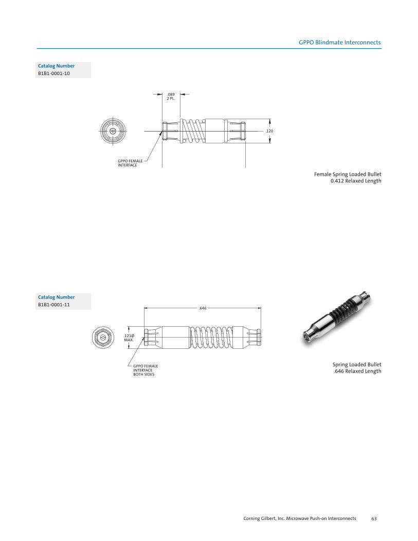
GPPO Blindmate Interconnects
.0892 PL.
.412
.120
GPPO FEMALEINTERFACEBOTH SIDES
Catalog Number
B1B1-0001-10
Female Spring Loaded Bullet0.412 Relaxed Length
.646
.121ØMAX.
GPPO FEMALEINTERFACEBOTH SIDES
Catalog Number
B1B1-0001-11
Spring Loaded Bullet.646 Relaxed Length
Corning Gilbert, Inc. Microwave Push-on Interconnects 63

Corning Gilbert, Inc. Microwave Push-on Interconnects64
GPPO Pins
.074
.025
.012Ø
.007
.023Ø
.019Ø
Catalog Number
Y071-L02-01
Catalog Number
Y071-L92-01
.170
.040
.012Ø .0035.0025
.0075
.0065


Corning Gilbert, Inc. Microwave Push-on Interconnects66
G3PO SpecificationsGeneral Characteristics
Impedance Frequency rangeTemperature range
Electrical Characteristics
VSWRInsertion lossDWV@ Sea Level:Insulation resistanceContact resistance
Outer conductorInner conductor
RF leakage
Mechanical Characteristics
Mate/Demate CyclesForce to engage/disengageTolerated misalignment
RadialAxial
Self-centering (male)*
Environmental Characteristics
Thermal ShockSalt SprayVibrationShockMoisture resistance
Materials (typical)
BodiesOuter contactsCenter contactsInsulatorsSprings
Finish (typical)
Bodies
Contacts
*Note: Corning Gilbert male connectors have a full self-centering mechanism
50 ohms nominalDC to 100 GHz-55oC thru 165oC
1.10:1 to 26.5 GHz typical; 1.25 : 1 typical to 65 GHz.12 f GHz250 Vrms3,500 megohms min.
2 milliohms max.6.0 milliohms max.-80 dB (typical mated pair)
Full Detent - 100min; Smooth Bore - 500min.Full Detent - 3.5lbs.typ./6.0lbs.typ.; SB - 1.6lbs.typ./2.5lbs.typ.
+/- 0.010”0.010” (flush to -0.010” from the reference plane)
MIL-STD-202, Method 107, Condition BMIL-STD-202, Method 101MIL-STD-202, Method 204MIL-STD-202, Method 213, Condition IMIL-STD-202, Method 106, except Step 7B
Beryllium Copper per ASTM B196 and or/ASTM B197Beryllium Copper per ASTM B196 and or/ASTM B197Beryllium Copper per ASTM B196 and or/ASTM B197PTFE Fluorocarbon per ASTM D1710 and ASTM D 145717-7 Stainless Steel per ASTM A313-95A
Gold plated per MIL-G-45204, Type I, Grade C, Class 1,Over Nickel Plate per QQ-N-290Gold plated per MIL-G-45204, Type I, Grade C, Class 1,Over Nickel Plate per QQ-N-290

G3PO PCB Mounts
.150
.050
.010 SOLDER DIP USINGSn63 Pb37
.009Ø
.012
.101
R / P
.090Ø
G3PO MALEFULL DETENTINTERFACE
Catalog Number
R008-L13-02
VSWR (TYP)
1.15:1 to 40 GHz
1.25:1 to 65 GHz
Male Full DetentPCB Thru Mount
G3PO MALECATCHERS MITTINTERFACE
.102Ø
.084 .031
.031
.027
.040
.027
.020Ø2 PL.
.010
.0602 PL.
Catalog Number
R008-L16-01
VSWR (TYP)
1.20:1 to 40 GHz
1.30:1 to 65 GHz
Male Catchers Mitt PCB Shroud with Nailhead Pin
Catalog Number A
R010-L13-03 FDR010-L15-03 SB
VSWR (TYP)
1.20:1 to 40 GHz
PCB Edge Mount
.123
.115Ø
G3PO MALETAB DETENT
INTERFACE
.041 2 PL.
.010Ø
.008Ø
.094
.043 2 PL.
.0172 PL.
.0082 PL.
Corning Gilbert, Inc. Microwave Push-on Interconnects 67
G3PO Edge Mounts

G3PO Edge Mounts
Catalog Number
R032-V53-01
VSWR (TYP)
1.20:1 to 40 GHz
Male Full DetentDual Port Edge Mount
.048
.216
.117
G3PO MALEFULL DETENTINTERFACE
.150
.212
R / P
.123
.2242 PL.
.0415 PL. .025
3 PL.
.0712 PL.
.0382 PL.
.015 X 45° 2 PL.
.266
.016Ø2 PL.
#00-96 THRU
G3PO Surface Mount
G3PO SMOOTH BOREINTERFACE
R / P
.049
.090Ø
.070Ø
.098
Catalog Number
R012-T95-01
Male Smooth Bore Solder Attach Shroud
Corning Gilbert, Inc. Microwave Push-on Interconnects68

G3PO Cable Connectors
Catalog Number
R014-B11-01
VSWR (TYP)
1.20:1 to 40 GHz
1.30:1 to 65 GHz
Female Straight to 0.047 S/R Cable
.238
.104Ø
.077Ø
.193
.133
CABLE STOP
.063Ø
G3PO FEMALEINTERFACE
Catalog Number A
R014-B13-01 FDR014-B15-01 SB
VSWR (TYP)
1.20:1 to 40 GHz
1.30:1 to 65 GHz
Male Straight to 0.047 S/R Cable
.104Ø
.090Ø
G3PO MALE"A" INTERFACE
R / P
.158
CABLE STOP
.077Ø
.252
Catalog Number
R014-K11-01
Female Straight to 0.058 Flex Cable G3PO FEMALEINTERFACE
R / P
.063Ø
.131
.193
.238
.123Ø
.077Ø
CABLE STOP
Corning Gilbert, Inc. Microwave Push-on Interconnects 69

G3PO Cable Connectors
G3PO MALELIMITED DETENTINTERFACE
.160
.074
.222
.267
.117
.115
.090
R / P
.1582 PL.
CABLE STOP
.0672 PL.
.275
Catalog Number
R033-K54-01
VSWR (TYP)
1.20:1 to 40 GHz
1.30:1 to 65 GHz
Male Limited DetentDual Port to 0.058 Flex Cable
G3PO Loads
G3PO FEMALEINTERFACE
.063Ø
.258
.052
.042
.104Ø2 PL.
Catalog Number
R055-A11-01
VSWR (TYP)
1.20:1 to 18 GHz
1.30:1 to 40 GHz
Female 50 Ohm Load
G3PO MALE"A" INTERFACE
.086Ø
.258
.104Ø
Catalog Number
R055-A13-01 FDR055-A15-01 SB
VSWR (TYP)
1.20:1 to 18 GHz
1.30:1 to 40 GHz
Male 50 Ohm Load
Corning Gilbert, Inc. Microwave Push-on Interconnects70
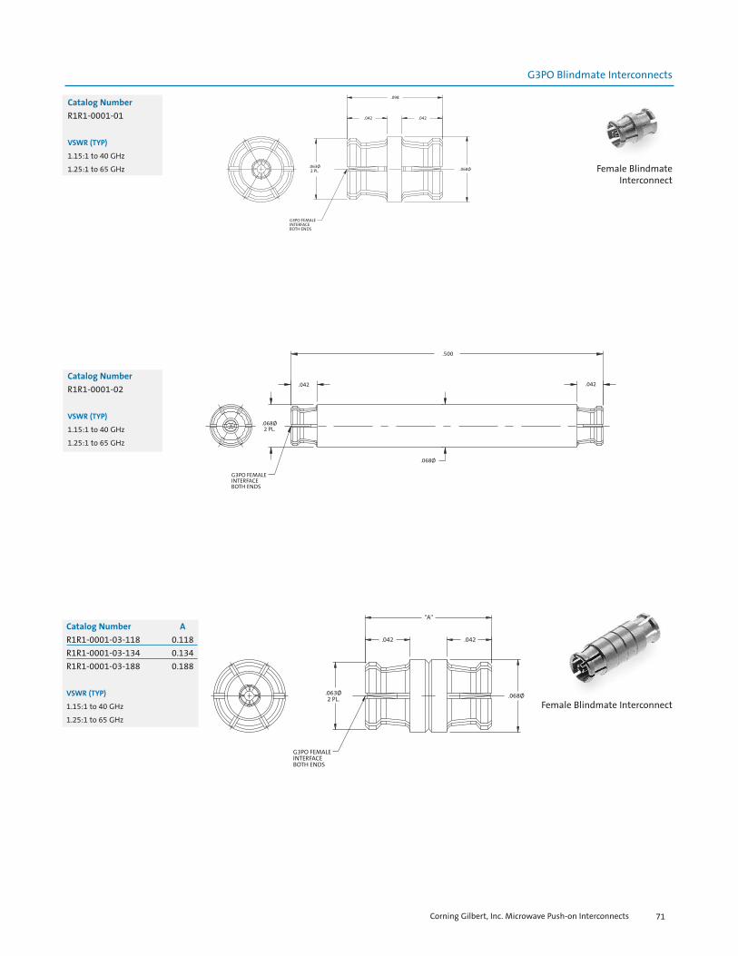
G3PO Blindmate Interconnects
Catalog Number A
R1R1-0001-03-118 0.118R1R1-0001-03-134 0.134R1R1-0001-03-188 0.188
VSWR (TYP)
1.15:1 to 40 GHz
1.25:1 to 65 GHz
Catalog Number
R1R1-0001-01
VSWR (TYP)
1.15:1 to 40 GHz
1.25:1 to 65 GHz
G3PO FEMALEINTERFACEBOTH ENDS
.063Ø2 PL.
"A"
.042 .042
.068Ø
Female Blindmate Interconnect
.063Ø2 PL.
G3PO FEMALEINTERFACEBOTH ENDS
.068Ø
.042.042
.098
Catalog Number
R1R1-0001-02
VSWR (TYP)
1.15:1 to 40 GHz
1.25:1 to 65 GHz
.068Ø2 PL.
G3PO FEMALEINTERFACEBOTH ENDS
.042
.500
.068Ø
.042
Female Blindmate Interconnect
Corning Gilbert, Inc. Microwave Push-on Interconnects 71

Corning Gilbert, Inc. Microwave Push-on Interconnects72
G3PO Pin
.009Ø
.016Ø
.074
.047
.042
.018Ø
Catalog Number
Y071-L02-02
Surface Mount Pin


GMS SpecificationsGeneral Characteristics
Impedance Frequency rangeTemperature range
Electrical Characteristics
VSWRInsertion lossDWV@ Sea Level:Insulation resistanceContact resistance
Outer conductorInner conductor
RF leakage
Mechanical Characteristics
DurabilityForce to engage/disengageTolerated misalignment
RadialAxial
Self-centering (male)*
Environmental Characteristics
Thermal ShockSalt SprayVibrationShockMoisture resistance
Materials (typical)
Bodies
Outer contactsCenter contactsInsulatorsSprings
Finish (typical)
Bodies
Contacts
*Note: Corning Gilbert male connectors have a full self-centering mechanism
50 ohms nominalDC to 23 GHz-55oC thru 165oC
1.20+.005x f(GHz) (typical mated pair).03x f GHz1,500 Vrms1,000 megohms min.
2 milliohms max.2.5 milliohms max.-80 dB (typical mated pair)
5000+ mate/demate cycles2.5 pounds max.
.020
.060
MIL-STD-202, Method 107, Condition BMIL-STD-202, Method 101MIL-STD-202, Method 204MIL-STD-202, Method 213, Condition IMIL-STD-202, Method 106, except Step 7B
CRES 303 per ASTM A484 and ASTM A582 and or/ASTM A555 and ASTM A581Beryllium Copper per ASTM B196 and or/ASTM B197Beryllium Copper per ASTM B196 and or/ASTM B197PTFE Fluorocarbon per ASTM D1710 and ASTM D 145717-7 Stainless Steel per ASTM A313-95A
Passivate per MIL-F-14072 E300Gold plated per MIL-G-45204, Type I, Grade C, Class 1,Over Nickel Plate per QQ-N-290
Corning Gilbert, Inc. Microwave Push-on Interconnects74

GMS Flange Mounts
.331
.060
.007
.003.101
.343Ø .180Ø
GMS JACKINTERFACE
.316Ø303 STAINLESS STEEL
.625Ø
.295Ø
18°4 PL.
.103Ø 2 PL.
.480
.240
Catalog Number
H001-N11-01
VSWR (TYP)
1.20:1 to 15 GHz
1.30:1 to 23 GHz
Jack 2 Hole Flange MountAccepts 0.015 C/C
.480 .625Ø .343Ø
GMS JACKINETRFACE
.333.297
.227
.162Ø
.050Ø
.633
.060Ø
R/P.103Ø2 PL.
Catalog Number
H001-L11-01
VSWR (TYP)
1.20:1 to 15 GHz
1.30:1 to 23 GHz
Jack 2 Hole Flange to Post Terminal
.103Ø2 PL.
.480
GMS JACKINTERFACE
.625Ø
.343Ø
R/P.333
.135
1
1
2
2
PIN SHIPPEDSEPARATELY
DIMENSION AS INSTALLED
.008 X .032 TAB
.100
.106Ø
.471
.060
Catalog Number
H001-M11-01
VSWR (TYP)
1.20:1 to 15 GHz
1.30:1 to 23 GHz
Jack 2 Hole Flange to Tab Terminal
Corning Gilbert, Inc. Microwave Push-on Interconnects 75
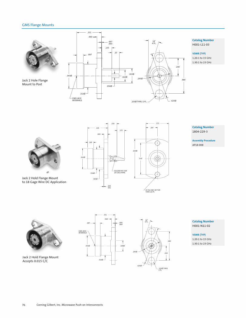
GMS Flange Mounts
.331
.060
.007
.003
.135
.10.087
.343Ø
.316Ø
GMS JACKINTERFACE
.202Ø.162Ø
.050Ø
.295Ø
.103Ø THRU 2 PL. .625Ø
.480
.240
18°4 PL.
Catalog Number
H001-L11-03
VSWR (TYP)
1.20:1 to 15 GHz
1.30:1 to 23 GHz
Jack 2 Hole Flange Mount to Post
.335
.065
.100
.343Ø
.316Ø
.365Ø
.150
.125
.005
.001
SOLDER POT FOR18 GAGE WIRE
.650Ø
.520
.187
.375
#2-56 UNC-2B THDTHRU (2) PL.
Catalog Number
1804-229-3
Assembly Procedure
AP18-008
Jack 2 Hold Flange Mountto 18 Gage Wire DC Application
.331
.060
.087
GMS JACKINTERFACE
.343Ø
.006
.004
.180Ø
.316Ø
18°4 PL.
.480
.240
.103Ø THRU2 PL.
.295Ø
.625Ø
Catalog Number
H001-N11-02
VSWR (TYP)
1.20:1 to 15 GHz
1.30:1 to 23 GHz
Jack 2 Hold Flange MountAccepts 0.015 C/C
Corning Gilbert, Inc. Microwave Push-on Interconnects76

GMS Flange Mounts
.325
.480
.240
.103Ø THRU2 PL.
.625Ø
GMS JACKINTERFACE
.316Ø
.343Ø
.087
.331
.060
.008
.002
.180Ø
Catalog Number
H001-N11-03
VSWR (TYP)
1.20:1 to 15 GHz
1.30:1 to 23 GHz
Jack 2 Hole Flange MountAccepts 0.015 C/C
.331
.060
.007
.003
.229
.100
.343Ø
GMS JACKINTERFACE
.316Ø
.100
.180Ø
.035Ø
.050Ø
.295Ø
18°4 PL.
.102Ø 2 PL.
.240 .625Ø
.480
Catalog Number
1816-204-3
Jack 2 Hole Flange Mountto Solder Pot Terminal
.331
.060
.10
.343Ø
.316Ø
GMS JACKINTERFACE
.006
.004
(.008)
.135
.10 WHENINSTALLED
.106Ø .180Ø
.320
.008TAB
.625Ø
.102ØTHRU4 PL.
.500SQ.
.340SQ.
Catalog Number
1812-400-3
VSWR (TYP)
1.20:1 to 15 GHz
1.30:1 to 23 GHz
Jack 4 Hole Flange Mountto Tab Terminal
Corning Gilbert, Inc. Microwave Push-on Interconnects 77

GMS Flange Mounts
.340
.170
.480
.240
.102Ø2 PL.
.625Ø
.060
.030Ø
.191Ø
CONTACT
DIELECTRIC
.630
.417
.413
.340
.050
.310Ø
(.184)
R / P
.240
.232
JGMS FEMALE FULL DETENTHIGH POWER INTERFACEACCEPTS .060Ø PIN CONTACT
Catalog Number
W001-L11-02
VSWR (TYP)
1.20:1 to 15 GHz
1.30:1 to 23 GHz
Female Full Detent High PowerShroud Straight Terminal
.038
60°.022
.010
.005
.340
.170
.480
.240
.625Ø
.102Ø2 PL.
CONTACT
DIELECTRIC
.191Ø .050
.100
.671
.417
.413
.340
.050
.310Ø
.240
.232 R / P
JGMS FEMALE SMOOTH BOREHIGH POWER INTERFACEACCEPTS .060Ø PIN CONTACT
Catalog Number
W001-L11-03
VSWR (TYP)
1.20:1 to 15 GHz
1.30:1 to 23 GHz
Female Smooth Bore HIgh PowerShroud Dog Leg Terminal
.340
.170
.480
.240
.102Ø2 PL.
.060
.030Ø
.625Ø
CONTACT
DIELECTRIC
.191Ø
.630
.417
.413
.340
.050
.310Ø
(.184)
R / P
.240
.232
JGMS FEMALE SMOOTH BOREHIGH POWER INTERFACEACCEPTS .060Ø PIN CONTACT
Catalog Number
W001-L11-01
VSWR (TYP)
1.20:1 to 15 GHz
1.30:1 to 23 GHz
Female Smooth Bore High PowerShroud Straight Terminal
Corning Gilbert, Inc. Microwave Push-on Interconnects78

GMS Thread-In Shrouds
RECOMMENDEDMOUNTING HOLE
.170
.060
.060
.021Ø
.018Ø2 PL.
3/8HEX STOCK
.087
.343Ø
GMS JACKINTERFACE
R / P
.326OUTER
CONDUCTOR
.005
.002
EXTENDEDHOUSING
1/4 - 36 UNS-2A THD.
.457
.331OUTERSHELL
.266 .120
.035MAX
.127Ø
.345Ø
Catalog Number
1816-203-3
VSWR (TYP)
1.20:1 to 15 GHz
1.30:1 to 23 GHz
Jack Thread Mountwith Special Launch
GMS JACKINTERFACE
R / P
.458
3/8HEX STOCK
.087
.343Ø
.266
.331HOUSING
.030
.119
.005
.002
1/4-36 UNS-2A THD.
EXTENDEDDIELECTRIC
.075
.350
.106Ø
.345Ø
.018Ø.032Ø
Catalog Number
1816-206-3
VSWR (TYP)
1.20:1 to 15 GHz
1.30:1 to 23 GHz
Jack Thread Mountwith Special Launch
3/8 HEXSTOCK
.087
GMS JACKINTERFACE
.343Ø
.035MAX.
.120DIELECTRIC
.032Ø
.018Ø
.457
.331
.2661/4-36 UNS-2A THD
.005
.002
.106Ø
.345Ø
PIN DETAIL
.310
.235
.105
.004
Catalog Number
H003-L11-01
VSWR (TYP)
1.20:1 to 15 GHz
1.30:1 to 23 GHz
Jack Thread Mountwith Special Launch
Corning Gilbert, Inc. Microwave Push-on Interconnects 79

(.750)3 PL.
.625
45°.101
.343Ø
GMS JACKINTERFACE
R / P
.319Ø
.313Ø
.625
.612
.152Ø
.148Ø.020
.127
.1233 PL.
.235
.231.050 .015Ø
.080
.076
.070
.0662 PL.
.070
.0662 PL.
.009
.0052 PL.
.290Ø
3/8 HEX GMS JACKINTERFACE
.343Ø
.457
.065.126
ACCEPTS.015Ø X .110MAX PIN
.209Ø
1/4 - 36 UNS - 2A
R/PR/P 3/8 HEX
.454
.095
.091PANEL
THICKNESS
.315.255
.169.194
GMS PLUGINTERFACE
.270Ø
.250ACROSS
FLATS
.252
R / P .239
.402Ø
.139
SNAPRING
.473Ø
.050ØCONTACT
.250 UNS-2A THD.
.159ØDIELECTRIC
GMS Thread-In Shrouds
Catalog Number
1815-606-3
GMS, Plug, Snap-in,Float Mount toCoplanar Waveguide
Catalog Number
H003-N11-01
VSWR (TYP)
1.20:1 to 15 GHz
1.30:1 to 23 GHz
Tools Recommended
9001-906-3
Assembly Procedure
AP18-005
Jack Thread-in Accepts 0.015 C/C
GMS Edge Mount
Catalog Number
1816-208-1
VSWR (TYP)
1.20: 1 to 15 GHz
Jack Edge Mount
Corning Gilbert, Inc. Microwave Push-on Interconnects80
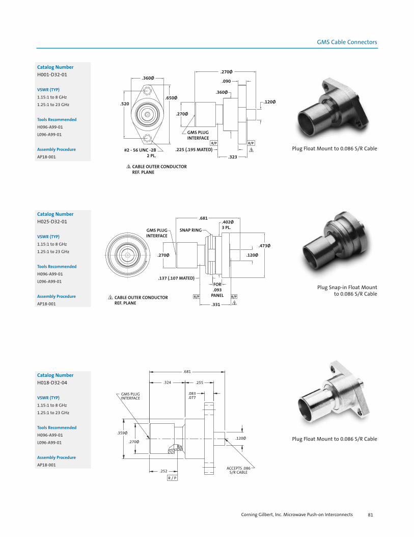
.681
.255.324
.083
.077GMS PLUGINTERFACE
.359Ø
.270Ø
.252
R / P
.120Ø
ACCEPTS .086S/R CABLE
1
1
CABLE OUTER CONDUCTORREF. PLANE
GMS PLUGINTERFACE
.270Ø
.137 (.107 MATED)
.681
SNAP RING
.402Ø3 PL.
.120Ø
.473Ø
R/P R/P
FOR.093
PANEL
.331
CABLE OUTER CONDUCTORREF. PLANE
#2 - 56 UNC -2B2 PL.
1
1
.360Ø
.520.650Ø
.270Ø
.090
.120Ø
.270Ø
GMS PLUGINTERFACE
R/P R/P
.323
.360Ø
.225 (.195 MATED)
GMS Cable Connectors
Catalog Number
H001-D32-01
VSWR (TYP)
1.15:1 to 8 GHz
1.25:1 to 23 GHz
Tools Recommended
H096-A99-01
L096-A99-01
Assembly Procedure
AP18-001
Plug Float Mount to 0.086 S/R Cable
Catalog Number
H025-D32-01
VSWR (TYP)
1.15:1 to 8 GHz
1.25:1 to 23 GHz
Tools Recommended
H096-A99-01
L096-A99-01
Assembly Procedure
AP18-001
Plug Snap-in Float Mountto 0.086 S/R Cable
Catalog Number
H018-D32-04
VSWR (TYP)
1.15:1 to 8 GHz
1.25:1 to 23 GHz
Tools Recommended
H096-A99-01
L096-A99-01
Assembly Procedure
AP18-001
Plug Float Mount to 0.086 S/R Cable
Corning Gilbert, Inc. Microwave Push-on Interconnects 81

.481
.103Ø2 PL.
GMS JACKINTERFACE
.625Ø.343Ø
R/P
.579
.120Ø
.465.267
.065 R/P
CABLE OUTER CONDUCTORREF. PLANE
1
1
.581
.335
.157
.065
.100
.125Ø
.343Ø .120Ø .180Ø
.057
GMS JACKINTERFACE
.316Ø
18°4 PL.
.102Ø2 PL.
.480
.625Ø
.240
.680
.322 .255.083.077
.095
.091PANELTHICKNESS
.270Ø
GMS PLUGINTERFACE .250
R / P
.151
.120Ø.402Ø
SNAP RING
ACCEPTS .086 S/RMP HAVERHILL CABLE
ACCEPTS CONTACT
DIELECTRIC STOP
.473Ø
GMS Cable Connectors
Catalog Number
H018-E32-01
Plug Float Mount Snap-In to 0.086 S/R MP Haverhill Cable
Catalog Number
H014-D11-02
VSWR (TYP)
1.15:1 to 8 GHz
1.25:1 to 23 GHz
Tools Recommended
A096-A99-09
L096-A99-01
Assembly Procedure
AP18-001Jack 2 Hole Flange Mountto 0.086 S/R Cable
Catalog Number
H001-D11-01
VSWR (TYP)
1.15:1 to 8 GHz
1.20:1 to 23 GHz
Tools Recommended
A096-A99-09
L096-A99-01
Assembly Procedure
AP18-001Jack 2 Hole Flange Mountto 0.086 S/R Cable
Corning Gilbert, Inc. Microwave Push-on Interconnects82

CABLE OUTER CONDUCTORREF. PLANE
11
.375ACROSS FLATS
2 PL.
.368Ø
GMS JACKINTERFACE
R/P R/P.465
.428
FOR .093PANEL
.120Ø .450Ø2 PL.
.568
GMS JACKINTERFACE
R / P
.325SNAP RING
ACCEPTS .086S/R CABLE
.581
.428
.095
.091PANEL
.228
.050
.402Ø
.473Ø.120Ø
.315
SNAPRINGGMS PLUG
INTERFACE
.270Ø
.250
R / P
.141
.403Ø
.401Ø
ACCEPTS .086S/R CABLE
FERRULE
.473Ø
.256
.254 .150 FOR PANEL
.257
GMS Cable Connectors
Catalog Number
H016-D11-01
VSWR (TYP)
1.15:1 to 8 GHz
1.20:1 to 23 GHz
Tools Recommended
A096-A99-09
L096-A99-01
Assembly Procedure
AP18-001Jack Bulkhead
to 0.086 S/R Cable
Catalog Number
H025-D11-01
VSWR (TYP)
1.30:1 to 23 GHz
Tools Recommended
A096-A99-09
L096-A99-01
Jack Snap Mountto 0.086 S/R Cable
Catalog Number
H018-D32-05
VSWR (TYP)
1.20:1 to 14 GHz
Tools Recommended
A096-A99-09
L096-A99-01
Assembly Procedure
AP18-006
Plug Snap Mountto 0.086 S/R Cable
Corning Gilbert, Inc. Microwave Push-on Interconnects 83

CABLE OUTER CONDUCTORREF. PLANE
1
1
.170Ø
.520
.798
.360Ø
#2 -56 UNC - 2B 2 PL.
GMS PLUGINTERFACE
.270Ø
R/P R/P
.833
.080.650Ø
.360Ø
.247(.217 MATED)
.703
.472.326
ACCESSCONTACT
1
1
CABLE OUTER CONDUCTORREF. PLANE
GMS PLUGINTERFACE
.270Ø
.148 (.118 MATED)
R/P R/P.208
.681
.402Ø 3 PL.
GMS ACCESSCONTACT
.473Ø
.180Ø
FOR .093 PANEL
CABLE OUTER CONDUCTORREF. PLANE
#2 - 56 UNC - 2B2 PL.
1
1
.520
.650Ø
.360Ø
GMS PLUGINTERFACE
.270Ø
.681.080
.180Ø
.360Ø
R/P R/P
.229.247
(.217 MATED)
GMS Cable Connectors
Catalog Number
H019-R32-01
Tools Recommended
H096-A99-01
L096-A99-10
Assembly Procedure
AP18-009
Plug Float Mount R/A Flange MountAccepts 0.141 S/R Cable
Catalog Number
H018-S32-01
Tools Recommended
H096-A99-01
L096-A99-10
Assembly Procedure
AP18-019
Plug Snap-in Float Mountto 0.141 Low Loss Cable
Catalog Number
H001-R32-01
VSWR (TYP)
1.14:1 to 18 GHz
1.35:1 to 23 GHz
Tools Recommended
H096-A99-01
L096-A99-10
Assembly Procedure
AP18-002
Plug 2 Hole Flange Float Mountto 0.141 Cable
Corning Gilbert, Inc. Microwave Push-on Interconnects84
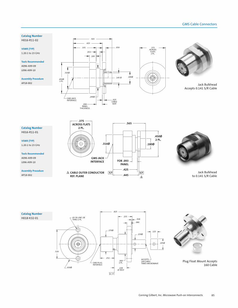
1
1
CABLE OUTER CONDUCTORREF. PLANE
R/P R/P
.375ACROSS FLATS
2 PL.
GMS JACKINTERFACE
.316Ø
.565
.450Ø2 PL.
.180Ø
.445
.425
FOR .093PANEL
.565
.425
.335 .050
.053
.100
.316Ø
.450Ø2 PL.
GMS JACKINTERFACE
.090PANEL
THICKNESS
.290Ø.025
CABLESEAT
.145 Ø .180Ø
.375ACROSS
FLATS2 PL.
#2-56 UNC-2BTHRU 2 PL.
.520
.650Ø
.825
.255.018
.080
.125
.195Ø
.159Ø
.270Ø
.252
R / P
.228AT REST
.3602 PL.GMS PLUG
INTERFACE
ACCEPTS160 CABLETIMES MICROWAVE
GMS Cable Connectors
Catalog Number
H016-R11-01
VSWR (TYP)
1.20:1 to 23 GHz
Tools Recommended
A096-A99-09
L096-A99-10
Assembly Procedure
AP18-002Jack Bulkhead
to 0.141 S/R Cable
Catalog Number
H016-R11-02
VSWR (TYP)
1.20:1 to 23 GHz
Tools Recommended
A096-A99-09
L096-A99-10
Assembly Procedure
AP18-002 Jack Bulkhead Accepts 0.141 S/R Cable
Catalog Number
H018-K32-01
Plug Float Mount Accepts 160 Cable
Corning Gilbert, Inc. Microwave Push-on Interconnects 85
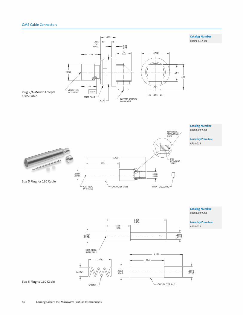
Size 5 Plug for 160 Cable
GMS Cable Connectors
.095
.091PANEL
.255
.323
.083
.077
1
.270Ø
.252
GMS PLUGINTERFACE
SNAP PLUG
R / P
.402ØACCEPTS SEMFLEX160S CABLE
.256
.420
.284
.473Ø
Catalog Number
H019-K32-01
Plug R/A Mount Accepts 160S Cable
1.420
.796
.276Ø
.274Ø
GMS PLUGINTERFACE
GMS OUTER SHELL FRONT DIELECTRIC
.159Ø
.157Ø
PTFERETAININGSLEEVE
OUTER SHELLCAPTIVATINGRIDGE
Catalog Number
H018-K12-01
Assembly Procedure
AP18-015
1.4061.404
.568
.566
.229Ø
.227Ø.159Ø.157Ø
GMS PLUGINTERFACE
17/32
7/32Ø .276Ø.274Ø
.255Ø
.253Ø
SPRING GMS OUTER SHELL
1.220
.796
Catalog Number
H018-K12-02
Assembly Procedure
AP18-012
Size 5 Plug to 160 Cable
Corning Gilbert, Inc. Microwave Push-on Interconnects86

GMS Cable Connectors
1.349
.350 GMS JACKINTERFACE
.159Ø .187Ø
.477
.143
.100Ø
CENTERINGDIELECTRIC
1.052
.050Ø
REAR DIELECTRIC
CONTACT
.065
.104Ø .195Ø
FERRULE
.125
Catalog Number
H014-K11-01
Assembly Procedure
AP18-011
Size 5 Jack to 160 Cable
1.349
.350
.159Ø
.050Ø
REAR DIELECTRIC
.065
.104Ø
CONTACT
1.052
.477
.143
.100Ø
CENTERDIELECTRIC
FERRULE
.125
195Ø
.187Ø
GMS JACKINTERFACE
Catalog Number
H014-K11-02
Assembly Procedure
AP18-011
Size 5 Jack to 160 Cable
.248ACROSS
FLATS
.088CONTACT
.008
.000DIELECTRIC
CONTACT
DIELECTRIC
.725
.171
.232Ø
.192Ø
5/16-32 UNEF-2A THD.ACCEPTS STORM
.180 S/R MP CABLE
.147 .062ØTHRU2 WALLS
Catalog Number
W014-K11-01
Assembly Procedure
AP18-014
HIgh Power Plug Straightto 0.180 S/R MP
Corning Gilbert, Inc. Microwave Push-on Interconnects 87

.350Ø
ACCEPTS STORM.180 S/R MP CABLE
.232Ø.192Ø .060Ø
+.008+.000
DIELECTRIC
.105 .500
.248
+_
R / P
DIELECTRICSTOP/GUIDE
.219Ø
.158Ø
.148
(.537)
.389
.890
.462
.430
.300
Ø.274+.002-.003
Ø.186
GMS JACKINTERFACE
Ø.218
Ø.314 +.002-.003
.573
.725
R / P
Ø.219MAX.
ACCEPTS STORM421-1001-001FLEX CABLE
CABLE STOP
Ø.186
GMS JACKINTERFACE
R / P
.573
.725
Ø.218
Ø.314 +.002-.003
Ø.274 +.002-.003
CABLE STOP
.300
.430
.462 .060Ø THRU (1) SIDE 2 PL.
.165Ø
ACCEPTS STORM421-010FLEX CABLE
.197Ø.215Ø
GMS Cable Connectors
Catalog Number
H015-K12-01
Assembly Procedure
AP18-016
High Power Plug R/A to 0.180 S/R MP Cable
Catalog Number
1890-023-1
Size 8 Contact with Female Interface for 421-1001-001 Flex Cable
Catalog Number
1890-025-1
Size 8 Contact with Female Interface for 421-010 Flex Cable
Corning Gilbert, Inc. Microwave Push-on Interconnects88
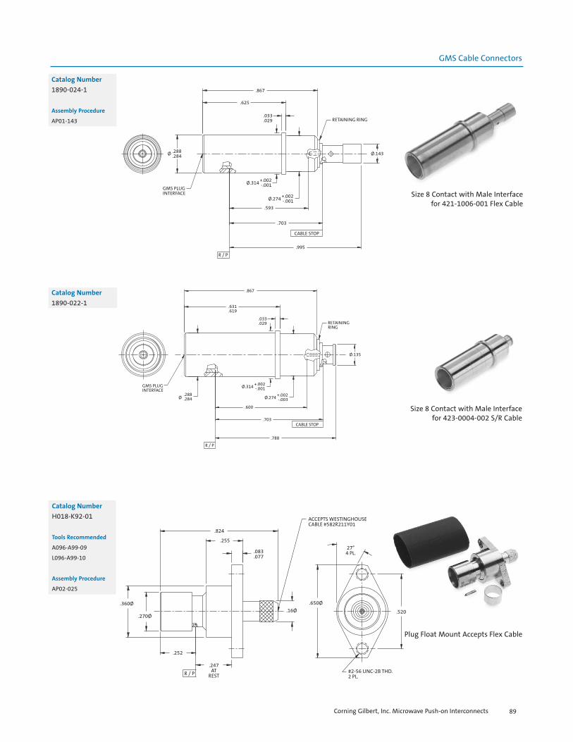
Ø .288.284
GMS PLUGINTERFACE
.625
.867
.033
.029 RETAINING RING
Ø.143
Ø.314 +.002-.001
Ø.274 +.002-.001
.593
.703
.995
CABLE STOP
R / P
.867
.631
.619
.033
.029 RETAININGRING
Ø.135
GMS PLUGINTERFACE
Ø.288.284
Ø.314 +.002-.001
Ø.274 +.002-.003
.600
.703
.788
R / P
CABLE STOP
ACCEPTS WESTINGHOUSECABLE #582R211Y01
#2-56 UNC-2B THD.2 PL.
.824
.255
.083
.077
.360Ø
.270Ø
.252
R / P
.247AT
REST
.16Ø.650Ø
.520
27°4 PL.
GMS Cable Connectors
Catalog Number
1890-024-1
Assembly Procedure
AP01-143
Size 8 Contact with Male Interface for 421-1006-001 Flex Cable
Catalog Number
1890-022-1
Size 8 Contact with Male Interface for 423-0004-002 S/R Cable
Catalog Number
H018-K92-01
Tools Recommended
A096-A99-09
L096-A99-10
Assembly Procedure
AP02-025
Plug Float Mount Accepts Flex Cable
Corning Gilbert, Inc. Microwave Push-on Interconnects 89
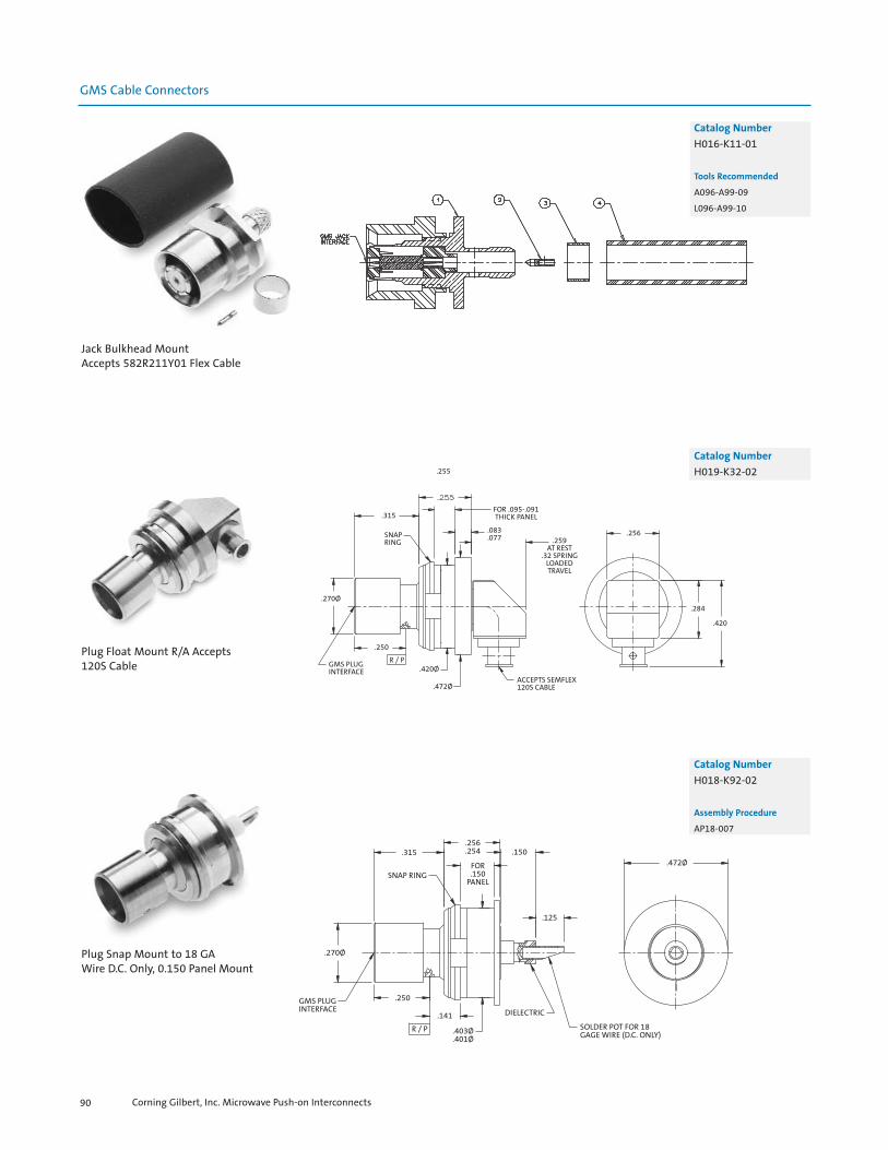
GMS Cable Connectors
Catalog Number
H016-K11-01
Tools Recommended
A096-A99-09
L096-A99-10
Jack Bulkhead MountAccepts 582R211Y01 Flex Cable
.315
SNAPRING
.270Ø
GMS PLUGINTERFACE
.250
R / P
.255
FOR .095-.091THICK PANEL
.083
.077
.420Ø
.472Ø
.259AT REST
.32 SPRINGLOADEDTRAVEL
ACCEPTS SEMFLEX120S CABLE
.256
.284
.420
Catalog Number
H019-K32-02
Plug Float Mount R/A Accepts120S Cable
GMS PLUGINTERFACE
.270Ø
.250
R / P
.315
SNAP RING
.256
.254
FOR.150
PANEL
.150
.125
.141
.403Ø
.401Ø
DIELECTRIC
SOLDER POT FOR 18GAGE WIRE (D.C. ONLY)
.472Ø
Catalog Number
H018-K92-02
Assembly Procedure
AP18-007
Plug Snap Mount to 18 GA Wire D.C. Only, 0.150 Panel Mount
Corning Gilbert, Inc. Microwave Push-on Interconnects90

.375ACROSS
FLATS 2 PL.GMS JACKINTERFACE
.450Ø .290Ø
.316Ø
.425 .050
.220
.090PANEL
THICKNESS
.100
.450Ø
.250Ø
.152ACROSS
FLATS
GMS Loads
GMS PLUGINTERFACE
.270Ø
.252
R / P
.360Ø
.152 ACROSSFLATS
.317
.829
.255
.09027°
4 PL.
.360Ø
.520
.260
.650Ø
#2-56 UNC-2B THD.THRU 2 PL.
Catalog Number
H055-A12-01
VSWR (TYP)
1.15:1 to 18 GHz
1.35:1 to 23 GHz
Plug 50 Ohm LoadFloat Mount
Catalog Number
H055-A11-01
Jack 50 Ohm Load Bulkhead
Corning Gilbert, Inc. Microwave Push-on Interconnects 91
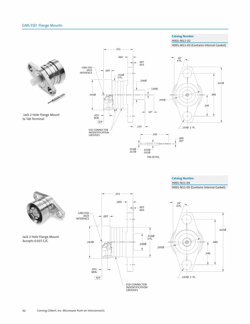
GMS ESD Flange Mounts
.331
.060
.007
.003
.087GMS ESD
JACKINTERFACE
.316Ø3 PL.
.106Ø
(.008)
.343Ø
.10*
.295Ø
.055MIN.
R/P
ESD CONNECTORINDENTIFICATIONGROOVES
.135
.320
.033Ø
.032Ø.019Ø.017Ø
PIN DETAIL
.009
.007
.103Ø 2 PL.
18°4 PL.
.625Ø
.480
.240
Catalog Number
H001-M11-02H001-M11-03 (Contains Internal Gasket)
Jack 2 Hole Flange Mountto Tab Terminal
.331
.060
.007
.003
.087GMS ESD
JACKINTERFACE
.316Ø3 PL.
.343Ø
.295Ø
.055MIN.
R/P
ESD CONNECTORINDENTIFICATIONGROOVES
.103Ø 2 PL.
18°4 PL.
.625Ø
.480
.240
.180Ø
Catalog Number
H001-N11-04H001-N11-05 (Contains Internal Gasket)
Jack 2 Hole Flange MountAccepts 0.015 C/C
Corning Gilbert, Inc. Microwave Push-on Interconnects92

.579
.270
O-RING.065
.087
.199Ø
.156Ø
.343Ø
GMS ESDJACK
INTERFACE
18°4 PL.
.625Ø
.075Ø
.285Ø
ACCEPTS.047 S/RCABLE
.480
.240
.103Ø 2 PL.R/P
.055MIN
.316Ø
.177
.242 CABLE STOP
.579
.335
.065.087
ESD CONNECTORIDENTIFICATION
GROOVES
GMS ESD JACKINTERFACE
.055 MIN.
R/P.316Ø
.199ØACCEPTS .086S/R CABLE
.120Ø
18°4 PL.
.103Ø2 PL.
.625Ø
.480
.240
.285Ø
.343Ø
R/P
.252
.117MAX
ACCEPTS.086 S/RCABLE
.360Ø
#2-56 UNC-2BTHD. 2 PL.
.260
.520
29°25°
4 PL.
.650Ø
GMS ESD PLUGINTERFACE
.270Ø
ESD CONNECTORIDENTIFICATIONGROOVES
.682
.255
.317
.093
.087
.120Ø
.360Ø
GMS ESD Cable Connectors
Corning Gilbert, Inc. Microwave Push-on Interconnects 93
Catalog Number
H014-B31-01
VSWR (TYP)
1.35:1 to 15 GHz
1.40:1 to 23 GHz
Tools Recommended
A096-A99-09
A096-A99-02
Assembly Procedure
AP18-022 Jack 2 Hole Flange Mount Rotatorto 0.047 S/R Cable
Jack 2 Hole Flange MountRotator to 0.086 S/R Cable
Plug 2 Hole Float Mountto 0.086 S/R Cable
Catalog Number A
H018-D32-07 0.090H018-D32-06 0.080
Tools Recommended
H096-A99-01
L096-A99-01
Assembly Procedure
AP18-001
Catalog Number
H014-D11-04H014-D11-05 (Contains Internal O-Ring)
Tools Recommended
A096-A99-09
L096-A99-01
Assembly Procedure
AP18-001

GMS ESD Cable Connectors
GMS ESDPLUGINTERFACE
ESD CONNECTORIDENTIFICATIONGROOVES
.270Ø
.681
.255
.083
.077
.359Ø.180Ø
.317
.252
R/P
.117 MAX.
.360Ø
ACCEPTS .141S/R CABLE
#2-56 UNC-2BTHD. 2 PL.
29°25°
4 PL.
.520
.260
.650Ø
Catalog Number
H018-R32-02
Tools Recommended
H096-A99-01
L096-A99-10
Plug 2 Hole Float Mountto 0.141 S/R Cable
GMS ESDPLUGINTERFACE
.270Ø
.315
.650
.255
.083
.077
.255
.249R/P
.361Ø
.355Ø
.650Ø .520
.260
.360Ø
27°4 PL.
Plug 50 Ohm Load2 Hole Flange Mount
GMS ESD Load
Catalog Number
H055-A32-02
Corning Gilbert, Inc. Microwave Push-on Interconnects94

SGMS Flange Mounts
.480
.083
.077
.008
.004.625Ø
.106Ø
.008
182Ø.270Ø
SGMS PLUGSMOOTH BOREINTERFACE
R/P.275.271
.135
.100
.500SQ.
.3402 PL.
.103ØTHRU4 PL.
.1702 PL.
Catalog Number
1811-400-3 SB1811-401-3 LD
Plug 4 Hole Flange MountTab Terminal
.773
.529
.329
R/P
.100
.125
.241
.481.220Ø
.158Ø
SGMS PLUGSMOOTH BOREINTERFACE
.037
.200
.063
.131Ø
.126ØTHRU 2 PL.
.073Ø
.068Ø
.125Ø2 PL.
THRU
CSK X 100°
.154
.030
.008
.250
.731
Catalog Number
P001-M35-01
Plug 4 Hole Flange MountTab Terminal
Corning Gilbert, Inc. Microwave Push-on Interconnects 95
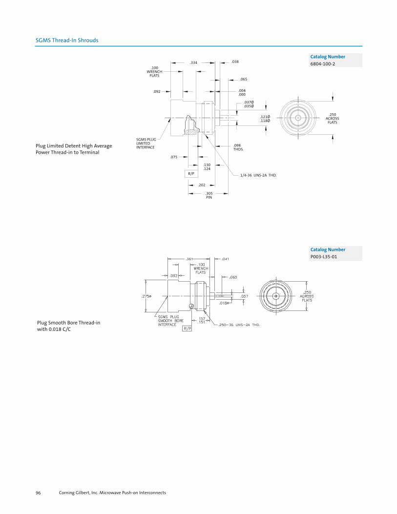
SGMS Thread-In Shrouds
.334 .038
.065
.004
.000
.037Ø
.035Ø
.100WRENCH
FLATS
.092
SGMS PLUGLIMITEDINTERFACE
.121Ø
.118Ø
.098THDS.
.075
R/P
.202
.305PIN
.130
.124
1/4-36 UNS-2A THD.
.250ACROSS
FLATS
Plug Limited Detent High AveragePower Thread-in to Terminal
Catalog Number
6804-100-2
Plug Smooth Bore Thread-inwith 0.018 C/C
Corning Gilbert, Inc. Microwave Push-on Interconnects96
Catalog Number
P003-L35-01

SGMS Cable Connectors
.375ACROSS
FLATS
5/16-48 UNS - 2A THD.
.236
.460Ø 1.375Ø.371Ø
.518
.202
.060
.275Ø
.201Ø
SGMS PLUGLIMITED DETENTINTERFACE
2 .075
R/P
.053Ø
.283
.046
.040
.313 ACROSS FLATS
.170Ø
.046
.040
Catalog Number
6804-100-3
Plug Limited Detent HighAverage Power Mount
to 0.141 S/R Cable
Plug 2-Hole Flange Mountfor 120 Cable
Catalog Number
P001-K94-01 LDP001-K95-01 SB
Corning Gilbert, Inc. Microwave Push-on Interconnects 97

SGMS Cable Connectors
Plug 2 Hole Flange Mountfor HP120 Cable
Catalog Number
P016-K94-01 LDP016-K95-01 SB
SGMS Blindmate Interconnect
.441
.439
.130BOTHENDS
.202Ø
.200Ø
SGMS FEMALEINTERFACEBOTH ENDS
.170BOTHENDS
.186ØBOTHENDS
Female Blindmate Interconnect
Catalog Number
1881-001-1
Corning Gilbert, Inc. Microwave Push-on Interconnects98

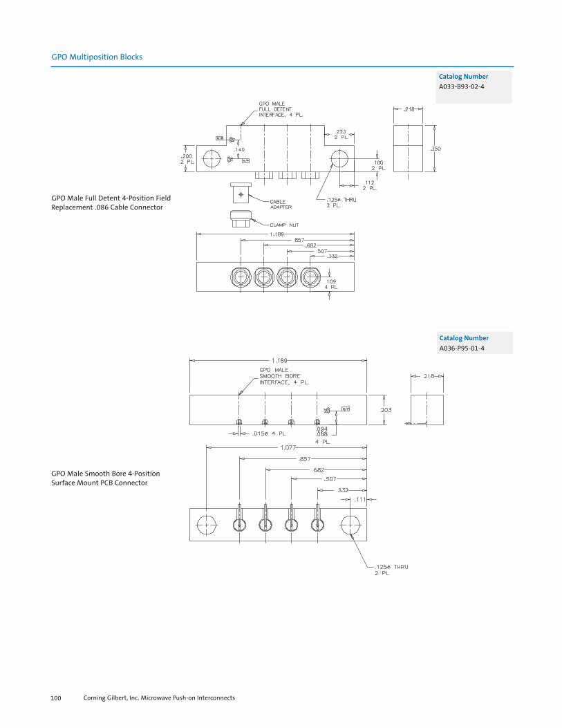
Corning Gilbert, Inc. Microwave Push-on Interconnects100
GPO Multiposition Blocks
GPO Male Full Detent 4-Position FieldReplacement .086 Cable Connector
Catalog Number
A033-B93-02-4
GPO Male Smooth Bore 4-PositionSurface Mount PCB Connector
Catalog Number
A036-P95-01-4

GPPO Multiposition Blocks
Corning Gilbert, Inc. Microwave Push-on Interconnects 101
GPO Multiposition Blocks
CABLE SIDE.073Ø2 PL.
.547
.030 X 45°8 PL.
.111Ø2 PL.
.264.3512 PL.
CABLE ADAPTERFOR .086 CABLE2 PL.
0-80 UNF - 2B2 PL.
.085
.169
.703
.210 [5.33]
.247
.078
Catalog Number
A033-D53-01
Male 2-Position Full Detent Connectorfor .086 S/R Cable
Male 2-Position Smooth BoreMounting Block
.127
.123
.089Ø
.085Ø2 PL.
.145
.141
.010
.008SLOT2 PL.
.020
.0142 PL.
FULL RAD. 2 PL.
.0125Ø
.0115Ø2 PL.
.102Ø
.098Ø2 PL.
.020SLOT2 PL.
.256
.254
.131
.129
.063
.030
.010 X 45° 4 PL.
GPPO MALESMOOTH BOREINTERFACE, 2 PL.
R / P
.061
.0592 PL.
.012
.0082 PL.
Catalog Number
B007-L45-02
Male 2-Position Smooth BoreMounting Block, Pre-Tinned
.012Ø2 PL.
.020
.0142 PL.
.010
.008 SLOT 2 PL.
.145
.141
.08
.04
PRE-TINPER MPS-160 .127
.123
.100Ø2 PL.
FULL RAD. 2 PL.
.020SLOT2 PL.
.012
.0082 PL.
.0602 PL.
R / P
GPPO MALESMOOTH BOREINTERFACE, 2 PL.
.255
.130
.063
.020 X 45° 4 PL.
Catalog Number
B007-L45-02-T

GPPO Multiposition Blocks
Corning Gilbert, Inc. Microwave Push-on Interconnects102
.145
.141"A" +/-.003 2 PL. *
.010
.008SLOT2 PL.
FULL RAD. 2 PL.
.012Ø2 PL.
.100Ø2 PL.
.012
.0082 PL.
.0602 PL.R / P
GPPO MALESMOOTH BOREINTERFACE, 2 PL. .020
SLOT2 PL.
.020 X 45° 4 PL.
.127
.123
.255
.130
.063
Male 2-Position Smooth BoreMounting Block
Catalog Number
B007-L45-04-TAB
TAB = “L” x 103 inches
B
.530
.100
.100
C
CABLEADAPTER
CLAMPNUT B
.560
.420
.210
.070
.175A
.250
.630
.116Ø THRU .170Ø .0502 PL.
Ø.010 A B C
Ø.010 A B C
C
.200
.050 MAXALLOWANCE FORCLAMP NUT
.250
R/P
A
.0834 PL.
.090
.560
.420
.210
B
.070
GPPO MALEFULL DETENTINTERFACE, 4 PL.
.175C
BOTTOMVIEW
Male 4-Position Full Detent R/Ato Storm 0.047 Flex Cable
Catalog Number
B031-B93-01-4

Ø.010 A B C
Ø.010 A B C
GPPO MALEFULL DETENTINTERFACE, 6 PL.
.820
.680
.515
.375
.210
.820
.680
.515
.375
.210
B
B
.070
.070
BOTTOMVIEW
.175
C
.116Ø THRU .170Ø .0502 PL.
.140
.750
C
.100
CABLEADAPTER
CLAMPNUT
.250
.890
.175A
.090
C
.200.250
.050 MAXALLOWANCE FORCLAMP NUT
R / P
A
.0836 PL.
Corning Gilbert, Inc. Microwave Push-on Interconnects 103
GPPO Multiposition Blocks
Catalog Number
B031-B93-01-6
Male 6-Position Full Detent R/Ato Storm 0.047 Flex Cable
.690
.550
.410270
.250.175
.960
.2002 PL.
CLAMPNUT
CABLEADAPTER
.860.075
.075
.110Ø THRU 2 PL.
.0502 PL.
.050 MAXALLOWANCE FORCLAMP NUT
.250
R / P
.0834 PL.
GPPO MALEFULL DETENTINTERFACE, 4 PL.
Male 4-Position Full Detent R/Ato Storm 0.047 Flex Cable
Catalog Number
B031-B93-02-4

Corning Gilbert, Inc. Microwave Push-on Interconnects104
GPPO Multiposition Blocks
.100
.100
.250
.590
.185
.175
.960.250
.0834 PL.
R / P
.050 MAXALLOWANCE FORCLAMP NUTS
CLAMP NUT
CABLE ADAPTER
.075
.100
.270
.410
.550
.690
.885
.105Ø THRU 2 PL.
Male 4-Position Full Detent R/Ato Storm 0.047 Flex Cable
Catalog Number
B031-B93-03-4
GPPO Multiposition Blocks

Corning Gilbert, Inc. Microwave Push-on Interconnects 105
GPPO Multiposition Blocks
Catalog Number
B010-A95-13
GPPO Smooth BoreDual Shroud Block
GPPO Male Full DetentDual Block R/A to
.086 Hand Formable Cable
Catalog Number
B011-A93-01

Corning Gilbert, Inc. Microwave Push-on Interconnects106
GPPO Multiposition Blocks
3-Position Straight GPPO Male Full Detent PWB Block Assembly
Catalog Number
B008-L13-05
7-Position GPPO Male R/A PWBBlock Assembly
Catalog Number
B030-L93-02-7B030-L95-02-7
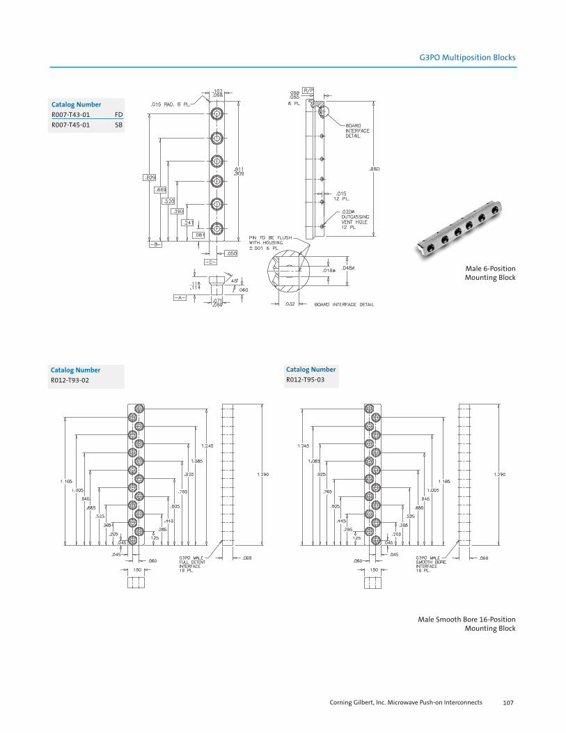
G3PO Multiposition Blocks
Catalog Number
R007-T43-01 FDR007-T45-01 SB
Male 6-PositionMounting Block
Male Smooth Bore 16-PositionMounting Block
Catalog Number
R012-T95-03
Corning Gilbert, Inc. Microwave Push-on Interconnects 107
Catalog Number
R012-T93-02
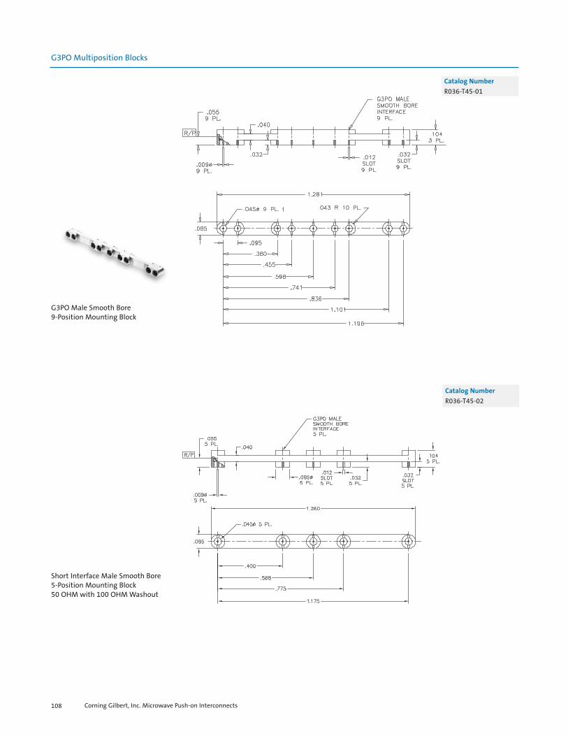
Corning Gilbert, Inc. Microwave Push-on Interconnects108
G3PO Multiposition Blocks
G3PO Male Smooth Bore9-Position Mounting Block
Short Interface Male Smooth Bore5-Position Mounting Block50 OHM with 100 OHM Washout
Catalog Number
R036-T45-02
Catalog Number
R036-T45-01

Corning Gilbert, Inc. Microwave Push-on Interconnects 109
SGMS Multiposition Blocks
Catalog Number
P031-G94-02-2
SGMS Plug Limited Detent2-Gang R/A Block to RD-316
SGMS Plug Smooth Bore2-Gang Straight PCB
Catalog Number
P032-L95-01-2

Corning Gilbert, Inc. Microwave Push-on Interconnects110
NOTES


Corning Gilbert, Inc. Microwave Push-on Interconnects112
GPO Within Series Adapters
Catalog Number
A1A3-0503-01 FDA1A4-0503-01 LDA1A5-0503-01 SB
VSWR (TYP)
1.20:1 to 18 GHz, 1.30:1 to 26.5 GHz
GPO Female to GPO Male
Catalog Number
0119-632-3
VSWR (TYP)
1.15:1 to 18 GHz,1.25:1 to 26.5 GHz
GPO Male CM toGPO Male FD Thread-in
Catalog Number
A3A6-0539-01 FD-CMA3A3-0539-01 FD-FD
VSWR (TYP)
1.15:1 to 18 GHz, 1.25:1 to 26.5 GHz
GPO Male toGPO Male Thread-in
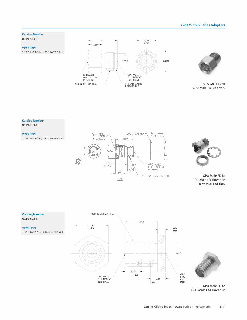
Corning Gilbert, Inc. Microwave Push-on Interconnects 113
GPO Within Series Adapters
Catalog Number
0119-843-3
VSWR (TYP)
1.15:1 to 18 GHz, 1.30:1 to 26.5 GHz
GPO Male FD toGPO Male FD Feed-thru
Catalog Number
0119-783-1
VSWR (TYP)
1.15:1 to 18 GHz, 1.30:1 to 26.5 GHz
GPO Male FD toGPO Male FD Thread-in
Hermetic Feed-thru
Catalog Number
0119-502-3
VSWR (TYP)
1.10:1 to 18 GHz, 1.20:1 to 26.5 GHz
GPO Male FD toGPO Male CM Thread-in

Corning Gilbert, Inc. Microwave Push-on Interconnects114
GPO Between Series Adapters
Catalog Number
1A3F1-0503-01 FD1A4F1-0503-01 LD1A5F1-0503-01 SB
VSWR (TYP)
1.10:1 to 18 GHz, 1.35:1 to 26.5 GHz
GPO Male to SMA Jack
Catalog Number
1A3F1-0523-01 FD1A4F1-0523-01 LD1A5F1-0523-01 SB
VSWR (TYP)
1.20:1 to 18 GHz, 1.30:1 to 26.5 GHz
GPO Male to SMA Jack Thread-in
Catalog Number
1A3F1-0523-02 FD1A4F1-0523-02 LD
VSWR (TYP)
1.10:1 to 18 GHz, 1.20:1 to 26.5 GHz
GPO Male to SMA Jack Thread-in

Corning Gilbert, Inc. Microwave Push-on Interconnects 115
GPO Between Series Adapters
Catalog Number
1A3F1-0523-05 FD1A5F1-0523-05 SB
VSWR (TYP)
1.10:1 to 18 GHz, 1.20:1 to 26.5 GHz
GPO Male to SMA Jack Thread-in
Catalog Number
1A3F1-0513-03 FD1A4F1-0513-03 LD1A5F1-0513-03 SB
VSWR (TYP)
1.10:1 to 18 GHz, 1.20:1 to 26.5 GHz
GPO Male toSMA Jack 2-Hole Flange Mount
Catalog Number
1A3F1-0513-05 FD1A4F1-0513-05 LD1A5F1-0513-05 SB
VSWR (TYP)
1.10:1 to 18 GHz, 1.20:1 to 26.5 GHz
GPO Male toSMA Jack 2-Hole Flange Mount
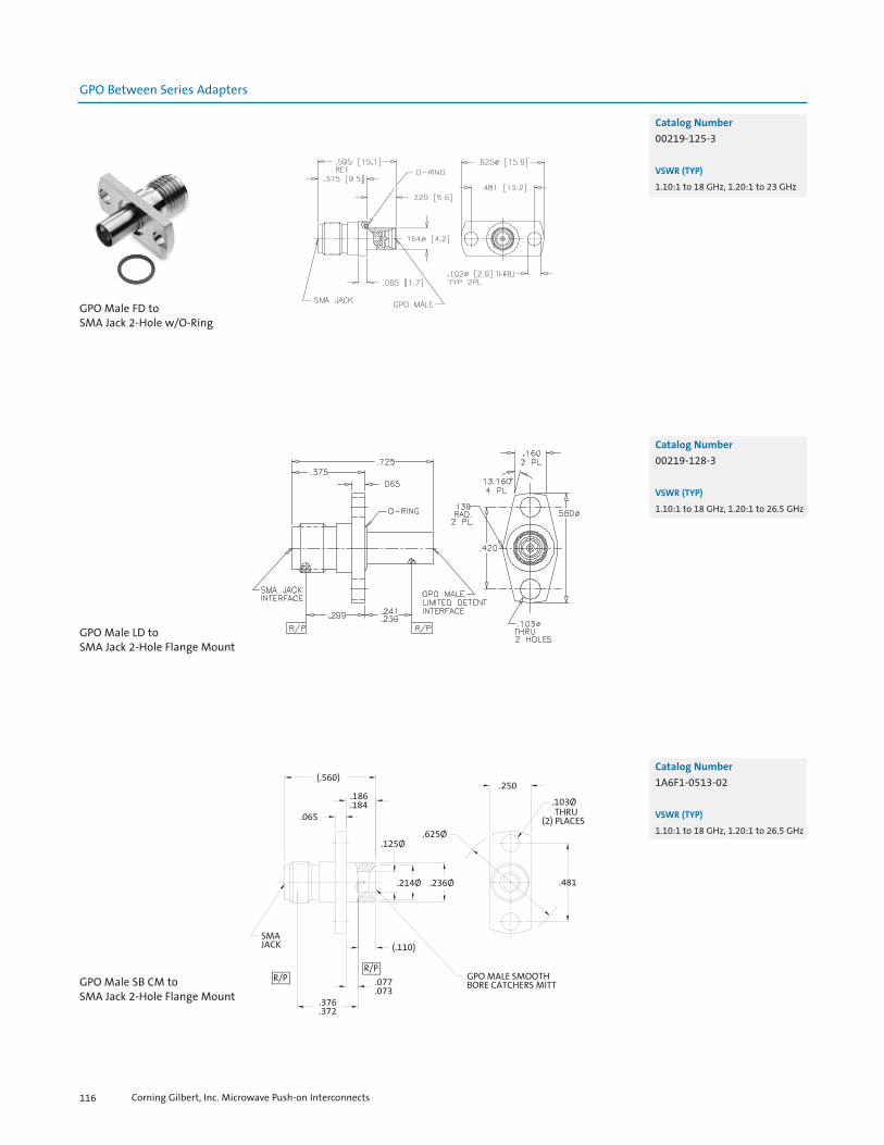
Corning Gilbert, Inc. Microwave Push-on Interconnects116
GPO Between Series Adapters
Catalog Number
00219-125-3
VSWR (TYP)
1.10:1 to 18 GHz, 1.20:1 to 23 GHz
GPO Male FD to SMA Jack 2-Hole w/O-Ring
Catalog Number
00219-128-3
VSWR (TYP)
1.10:1 to 18 GHz, 1.20:1 to 26.5 GHz
GPO Male LD to SMA Jack 2-Hole Flange Mount
Catalog Number
1A6F1-0513-02
VSWR (TYP)
1.10:1 to 18 GHz, 1.20:1 to 26.5 GHz
GPO Male SB CM to SMA Jack 2-Hole Flange Mount

Corning Gilbert, Inc. Microwave Push-on Interconnects 117
GPO Between Series Adapters
Catalog Number
00219-142-3-V10
VSWR (TYP)
1.10:1 to 18 GHz, 1.20:1 to 26.5 GHz
GPO Male FD toSMA Jack 4-Hole Flange Mount
Catalog Number
1A3F1-0513-02 FD1A5F1-0513-02 SB
VSWR (TYP)
1.10:1 to 18 GHz, 1.20:1 to 26.5 GHz
GPO Male toSMA Jack 4-Hole Flange Mount
Catalog Number
1A3F1-0513-04
VSWR (TYP)
1.10:1 to 18 GHz, 1.20:1 to 26.5 GHz
GPO Male FD toSMA Jack 4-Hole Flange Mount
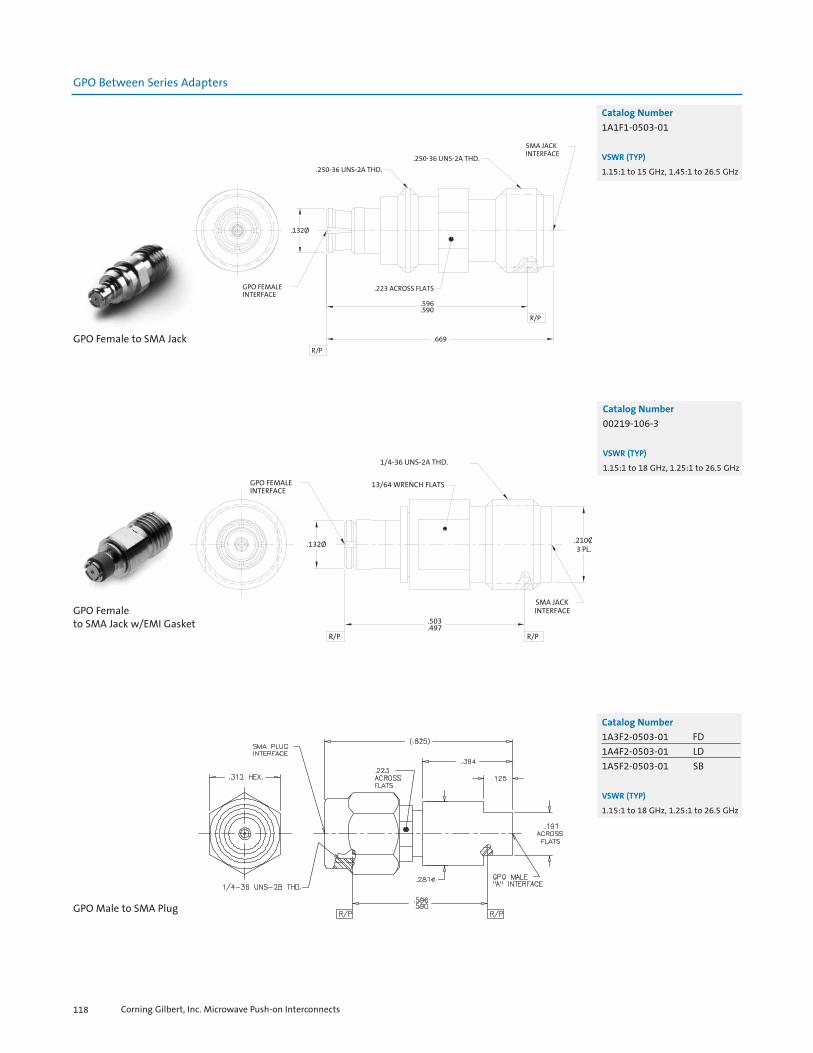
Corning Gilbert, Inc. Microwave Push-on Interconnects118
GPO Between Series Adapters
Catalog Number
1A1F1-0503-01
VSWR (TYP)
1.15:1 to 15 GHz, 1.45:1 to 26.5 GHz
GPO Female to SMA Jack
Catalog Number
00219-106-3
VSWR (TYP)
1.15:1 to 18 GHz, 1.25:1 to 26.5 GHz
GPO Femaleto SMA Jack w/EMI Gasket
Catalog Number
1A3F2-0503-01 FD1A4F2-0503-01 LD1A5F2-0503-01 SB
VSWR (TYP)
1.15:1 to 18 GHz, 1.25:1 to 26.5 GHz
GPO Male to SMA Plug
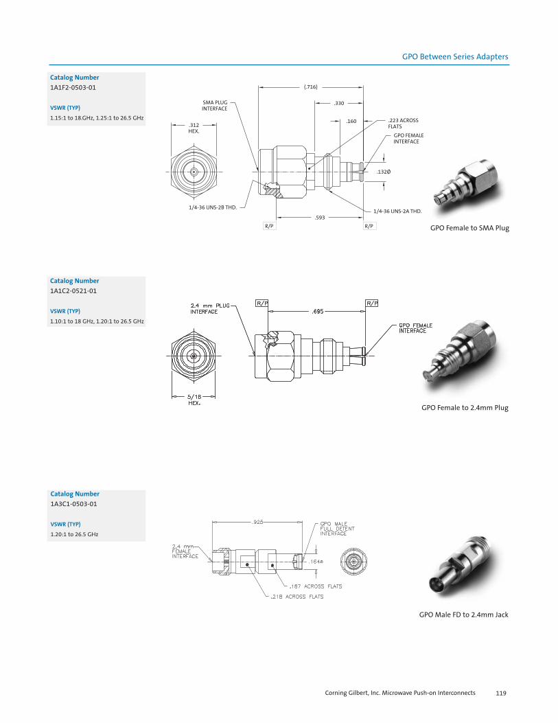
Corning Gilbert, Inc. Microwave Push-on Interconnects 119
GPO Between Series Adapters
Catalog Number
1A1F2-0503-01
VSWR (TYP)
1.15:1 to 18.GHz, 1.25:1 to 26.5 GHz
GPO Female to SMA Plug
Catalog Number
1A1C2-0521-01
VSWR (TYP)
1.10:1 to 18 GHz, 1.20:1 to 26.5 GHz
GPO Female to 2.4mm Plug
Catalog Number
1A3C1-0503-01
VSWR (TYP)
1.20:1 to 26.5 GHz
GPO Male FD to 2.4mm Jack

Corning Gilbert, Inc. Microwave Push-on Interconnects120
GPO Between Series Adapters
Catalog Number
1A1D1-0501-01
VSWR (TYP)
1.20 to 26.5 GHz
GPO Female to 2.92mm Jack
Catalog Number
1A1D2-0501-01
VSWR (TYP)
1.10:1 to 18 GHz, 1.25:1 to 26.5 GHz
GPO Female to 2.92mm Plug
Catalog Number
1A3D1-0503-01 FD1A4D1-0503-01 LD1A5D1-0503-01 SB
VSWR (TYP)
1.20:1 to 26.5 GHz
GPO to 2.92mm Jack
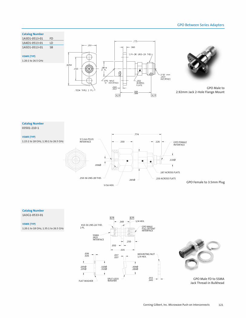
Corning Gilbert, Inc. Microwave Push-on Interconnects 121
GPO Between Series Adapters
Catalog Number
1A3D1-0513-01 FD1A4D1-0513-01 LD1A5D1-0513-01 SB
VSWR (TYP)
1.20:1 to 26.5 GHz
GPO Male to2.92mm Jack 2-Hole Flange Mount
Catalog Number
03501-210-1
VSWR (TYP)
1.15:1 to 18 GHz, 1.30:1 to 26.5 GHz
Catalog Number
1A3G1-0533-01
VSWR (TYP)
1.20:1 to 18 GHz, 1.35:1 to 26.5 GHz
GPO Male FD to SSMAJack Thread-in Bulkhead
GPO Female to 3.5mm Plug
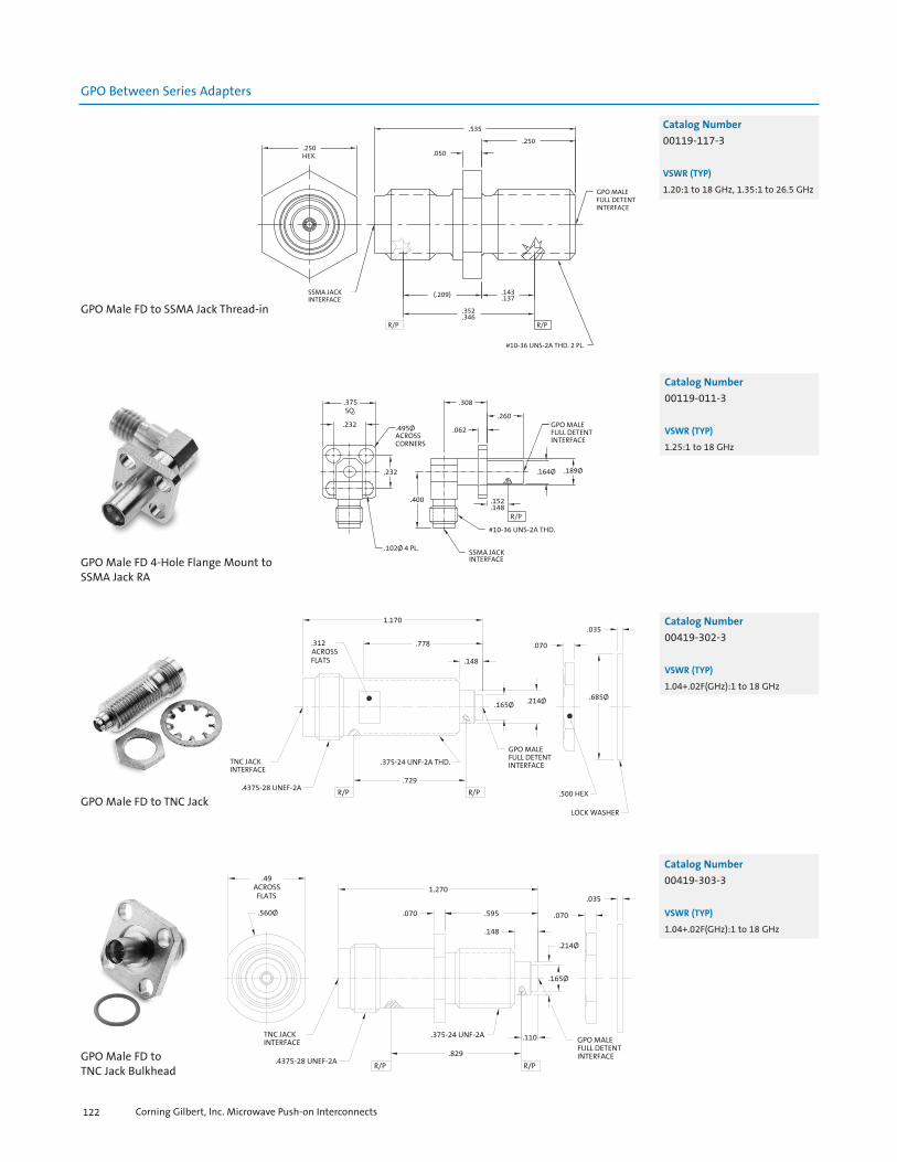
Corning Gilbert, Inc. Microwave Push-on Interconnects122
GPO Between Series Adapters
Catalog Number
00119-117-3
VSWR (TYP)
1.20:1 to 18 GHz, 1.35:1 to 26.5 GHz
GPO Male FD to SSMA Jack Thread-in
Catalog Number
00119-011-3
VSWR (TYP)
1.25:1 to 18 GHz
GPO Male FD 4-Hole Flange Mount toSSMA Jack RA
Catalog Number
00419-302-3
VSWR (TYP)
1.04+.02F(GHz):1 to 18 GHz
GPO Male FD to TNC Jack
Catalog Number
00419-303-3
VSWR (TYP)
1.04+.02F(GHz):1 to 18 GHz
GPO Male FD to TNC Jack Bulkhead

Corning Gilbert, Inc. Microwave Push-on Interconnects 123
GPPO Within Series Adapters
Catalog Number
B3B3-0523-01 FD-FDB5B3-0523-01 SB-FD
VSWR (TYP)
1.20:1 to 26.5 GHz, 1.30:1 to 40 GHz
GPPO Male to GPPO Male Thread-in
Catalog Number A B
B3B3-0523-02 FD-FDB3B5-0523-02 FD-SBB5B3-0523-02 SB-FDB5B5-0523-02 SB-SB
VSWR (TYP)
1.20:1 to 26.5 GHz, 1.30:1 to 40 GHz
GPPO Male to GPPO Male Thread-in
Catalog Number
1B1A3-0541-01
VSWR (TYP)
1.20:1 to 26.5 GHz, 1.30:1 to 40 GHz
GPPO Female Snap-inBulkhead Mount to GPO Male FD
GPPO Between Series Adapters

Corning Gilbert, Inc. Microwave Push-on Interconnects124
GPPO Between Series Adapters
Catalog Number
1B1F1-0503-01
VSWR (TYP)
1.15:1 to 12 GHz, 1.30:1 to 26.5 GHz
GPPO Female to SMA Jack
Catalog Number
1B1F2-0503-01
VSWR (TYP)
1.20:1 to 26.5 GHz
GPPO Female to SMA Plug
Catalog Number
1B3F1-0503-01 FD1B5F1-0503-01 SB
VSWR (TYP)
1.10:1 to 12 GHz, 1.20:1 to 26.5 GHz
GPPO Male to SMA Jack

Corning Gilbert, Inc. Microwave Push-on Interconnects 125
GPPO Between Series Adapters
Catalog Number
1B3F2-0503-01 FD1B5F2-0503-01 SB
VSWR (TYP)
1.15:1 to 18 GHz, 1.25:1 to 26.5 GHz.
GPPO Male to SMA Plug
Catalog Number
1B1C1-0501-01
VSWR (TYP)
1.10:1 to 18 GHz, 1.20:1 to 40 GHz
GPPO Female to 2.4mm Jack
Catalog Number
1B1C2-0501-01
VSWR (TYP)
1.20:1 to 26.5 GHz, 1.30:1 to 40 GHz
GPPO Female to 2.4mm Plug
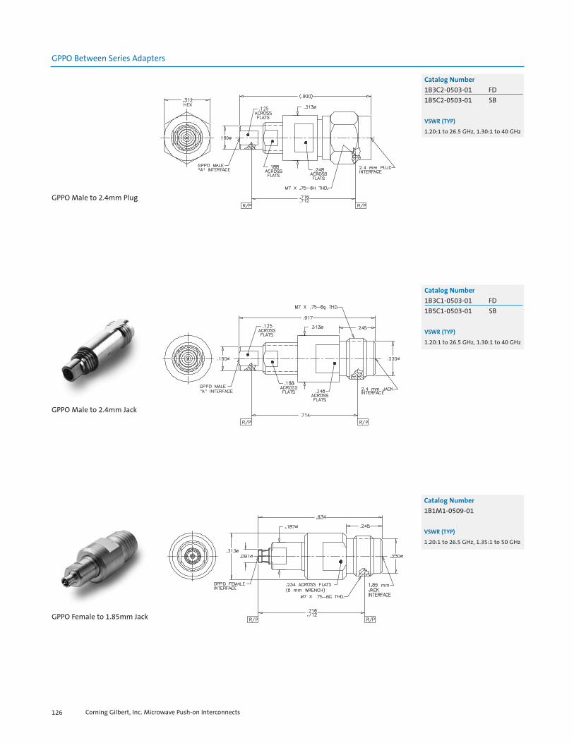
Corning Gilbert, Inc. Microwave Push-on Interconnects126
GPPO Between Series Adapters
Catalog Number
1B3C2-0503-01 FD1B5C2-0503-01 SB
VSWR (TYP)
1.20:1 to 26.5 GHz, 1.30:1 to 40 GHz
GPPO Male to 2.4mm Plug
Catalog Number
1B3C1-0503-01 FD1B5C1-0503-01 SB
VSWR (TYP)
1.20:1 to 26.5 GHz, 1.30:1 to 40 GHz
GPPO Male to 2.4mm Jack
Catalog Number
1B1M1-0509-01
VSWR (TYP)
1.20:1 to 26.5 GHz, 1.35:1 to 50 GHz
GPPO Female to 1.85mm Jack
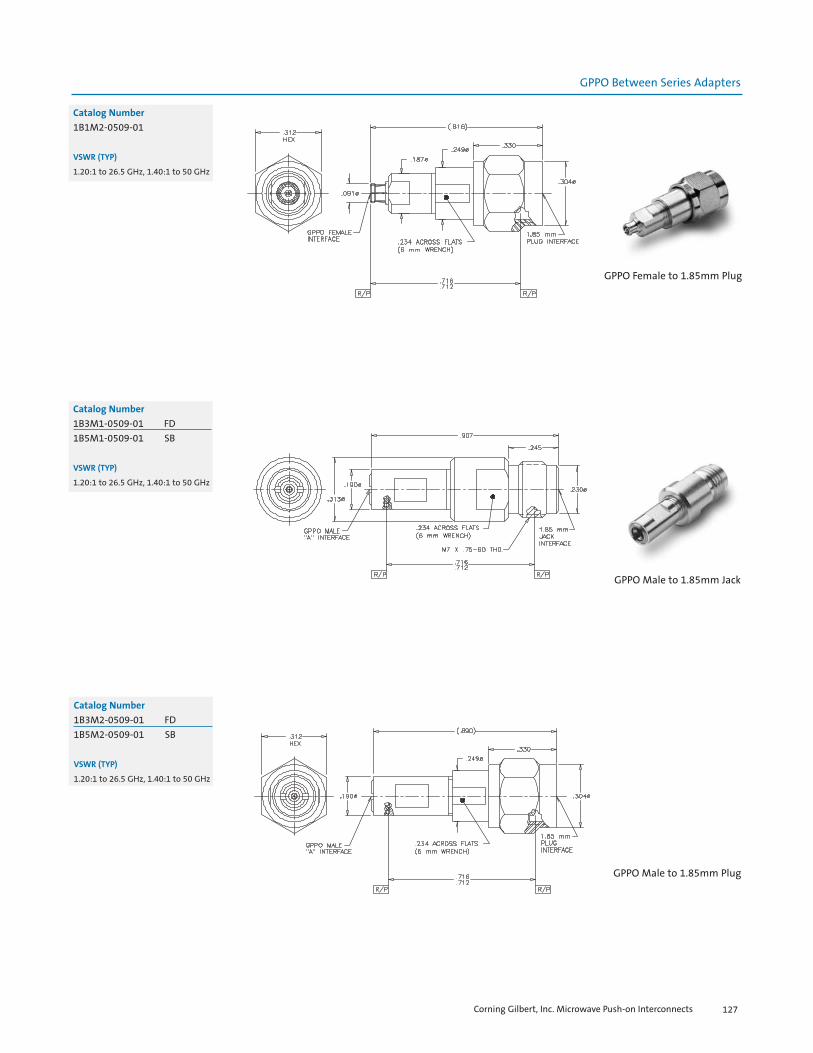
Corning Gilbert, Inc. Microwave Push-on Interconnects 127
GPPO Between Series Adapters
Catalog Number
1B1M2-0509-01
VSWR (TYP)
1.20:1 to 26.5 GHz, 1.40:1 to 50 GHz
GPPO Female to 1.85mm Plug
Catalog Number
1B3M1-0509-01 FD1B5M1-0509-01 SB
VSWR (TYP)
1.20:1 to 26.5 GHz, 1.40:1 to 50 GHz
GPPO Male to 1.85mm Jack
Catalog Number
1B3M2-0509-01 FD1B5M2-0509-01 SB
VSWR (TYP)
1.20:1 to 26.5 GHz, 1.40:1 to 50 GHz
GPPO Male to 1.85mm Plug

Corning Gilbert, Inc. Microwave Push-on Interconnects128
G3PO Adapters
Catalog Number
1R3M1-0509-01 FD1R5M1-0509-01 SB
VSWR (TYP)
1.20:1 to 26.5 GHz, 1.30:1 to 65 GHz
G3PO to 1.85mm Jack
Catalog Number
1R3F1-0509-01 FD1R5F1-0509-01 SB
VSWR (TYP)
1.20:1 to 18 GHz, 1.30:1 to 26 GHz
G3PO Male to SMA Jack
Catalog Number
00218-103-3
VSWR (TYP)
1.20:1 to 18 GHz, 1.30:1 to 23 GHz
GMS Jack to SMA Jack
GMS Adapters

Corning Gilbert, Inc. Microwave Push-on Interconnects 129
GMS Adapters
Catalog Number
1F1H2-0503-01
VSWR (TYP)
1.10:1 to 18 GHz, 1.20:1 to 23 GHz
GMS Plug to SMA Jack
Catalog Number
00218-301-3
VSWR (TYP)
1.20:1 to 18 GHz, 1.30:1 to 23 GHz
GMS Plug to SMA Jack
Catalog Number
1F1H1-0501-01
VSWR (TYP)
1.20:1 to 18 GHz, 1.30:1 to 23 GHz
GMS Jack to SMA Jack

Corning Gilbert, Inc. Microwave Push-on Interconnects130
Catalog Number
00218-101-3
VSWR (TYP)
1.20:1 to 18 GHz, 1.30:1 to 23 GHz
GMS Jack to SMA Jack
Catalog Number
1F2H1-0501-01
VSWR (TYP)
1.20:1 to 23 GHz
GMS Jack to SMA Plug
Catalog Number
1F2H2-0503-01
VSWR (TYP)
1.20:1 to 18 GHz, 1.30:1 to 23 GHz
GMS Plug to SMA Plug
GMS Adapters

Corning Gilbert, Inc. Microwave Push-on Interconnects 131
Catalog Number
00218-201-3
VSWR (TYP)
1.20:1 to 18 GHz, 1.30:1 to 23 GHz
GMS Jack to SMA Plug
Catalog Number
00218-104-3
VSWR (TYP)
1.20:1 to 18 GHz, 1.30:1 to 23 GHz
GMS Jack to SMA JackBulkhead Mount Adapter
Catalog Number
00218-202-3
VSWR (TYP)
1.20:1 to 18 GHz, 1.30:1 to 23 GHz
GMS Jack to SMA PlugBulkhead Mount Adapter
GMS Adapters
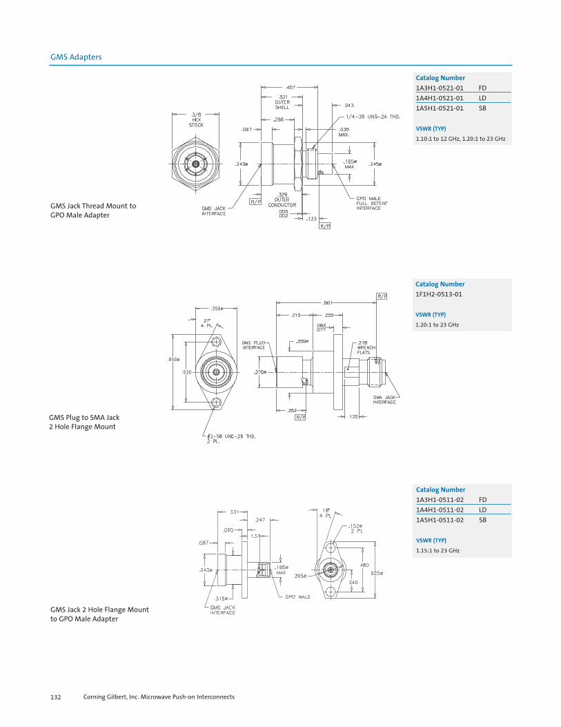
Corning Gilbert, Inc. Microwave Push-on Interconnects132
Catalog Number
1A3H1-0521-01 FD1A4H1-0521-01 LD1A5H1-0521-01 SB
VSWR (TYP)
1.10:1 to 12 GHz, 1.20:1 to 23 GHz
GMS Jack Thread Mount toGPO Male Adapter
Catalog Number
1F1H2-0513-01
VSWR (TYP)
1.20:1 to 23 GHz
GMS Plug to SMA Jack2 Hole Flange Mount
Catalog Number
1A3H1-0511-02 FD1A4H1-0511-02 LD1A5H1-0511-02 SB
VSWR (TYP)
1.15:1 to 23 GHz
GMS Jack 2 Hole Flange Mountto GPO Male Adapter
GMS Adapters

Corning Gilbert, Inc. Microwave Push-on Interconnects 133
Catalog Number
1A3H1-0511-01
VSWR (TYP)
1.20:1 to 23 GHz
GMS Jack 2-Hole Flange Mountto GPO Male FD Adapter
Catalog Number
1A3H2-0533-01
VSWR (TYP)
1.20:1 to 18 GHz, 1.30:1 to 23 GHz
GMS Plug to GPO Male FDSnap-in Float Mount
Catalog Number
00118-119-3-LD
VSWR (TYP)
1.20:1 to 18 GHz, 1.30:1 to 23 GHz
GMS Jack to GPO Male LDBulkhead Mount
GMS Adapters

Corning Gilbert, Inc. Microwave Push-on Interconnects134
Catalog Number
02018-318-3
VSWR (TYP)
1.20:1 to 18 GHz, 1.30:1 to 23 GHz
GMS ESD Male Plug to SMA Jack
Catalog Number
02018-317-3
VSWR (TYP)
1.20:1 to 18 GHz, 1.30:1 to 23 GHz
GMS ESD Jack to SMA Plug
Catalog Number
02018-316-3
VSWR (TYP)
1.20:1 to 18 GHz, 1.30:1 to 23 GHz
GMS ESD Plug to SMA Plug
GMS ESD Adapters

Corning Gilbert, Inc. Microwave Push-on Interconnects 135
Catalog Number
02018-315-3
VSWR (TYP)
1.20:1 to 18 GHz, 1.30:1 to 23 GHz
GMS ESD Plug Float Mountto SMA Jack
Catalog Number
02018-320-4
VSWR (TYP)
1.20:1 to 18 GHz, 1.30:1 to 23 GHz
GMS ESD Jack 2-Hole Flange Mountto GPO Male FD
GMS ESD Adapters

Corning Gilbert, Inc. Microwave Push-on Interconnects136
NOTES

Corning Gilbert, Inc. Microwave Push-on Interconnects138
GPO Tools
Catalog Number
A090-A99-01
GPO Seal Locating Tool for Thread-in Shroud
GPO Shroud Centering Toolfor .015 C/C
GPO Seal Locating Toolfor Thread-in Shroud
Flange Seal Locator Toolfor .481 Hole
Catalog Number
A090-A99-03
Catalog Number
A090-A99-07
Catalog Number
A090-A99-09

Corning Gilbert, Inc. Microwave Push-on Interconnects 139
GPO Tools
Flange Seal Locator Toolfor .282 Hole
Flange Seal Locator Toolfor .328 Hole
GPO Contact Retaining Tool
GPO Contact Locating Tool
Catalog Number
A090-A99-11
Catalog Number
A096-A99-02
Catalog Number
A096-A99-01
Catalog Number
A090-A99-10

Corning Gilbert, Inc. Microwave Push-on Interconnects140
GPO Tools
Catalog Number
A096-A99-04
GPO Contact Locating Tool
GPO Female Locator Tool
GPO R/A Locator Toolfor Round Housing
GPO R/A Locator Toolfor Square Housing
Catalog Number
A096-A99-06
Catalog Number
A096-A99-07
Catalog Number
A096-A99-08

Corning Gilbert, Inc. Microwave Push-on Interconnects 141
GPO Tools
GPO R/A Locator Tool
GPO Female R/A Installation Tool
GPO Low Impact BMI Removal Tool
GPO Low Impact Cable ConnectorRemoval Tool
Catalog Number
A098-A99-04
Catalog Number
A098-A98-08
Catalog Number
A095-A99-03*
* Additional alternate tips availablefor use with this tool:
A099-A99-02-395(for A1A1-001-14 Bullet)
A099-A99-02-485(for A1A1-001-10 Bullet)
Catalog Number
A096-A99-09

Corning Gilbert, Inc. Microwave Push-on Interconnects142
GPO Tools
Catalog Number
A093-A99-01
GPO Low Impact Load Removal Tool
GPO R/A Removal Tool
Installation/Withdrawal Tool(GPO R/A and Cable)
GPO Pry Bar Removal Tool
Catalog Number
A098-A99-01
Catalog Number
A098-A99-02
Catalog Number
A098-A99-03

Corning Gilbert, Inc. Microwave Push-on Interconnects 143
GPO Tools
GPO Snap-in Float MountRemoval Tool
GPPO Seal Locator Toolfor Thread-in Shroud
GPPO Contact Retaining Tool
Catalog Number
B090-A99-05
Catalog Number
B096-A93-01
Catalog Number
A098-A99-05
GPPO Tools
GPO Straight Cable ConnectorRemoval Tool
Catalog Number
A098-A99-10

GPPO Locator Tool
Corning Gilbert, Inc. Microwave Push-on Interconnects144
GPPO Tools
Catalog Number
B098-A99-01
GPPO Female R/A Installation Tool
GPPO 30° Removal Tool
GPPO Removal Tool
Catalog Number
B098-A99-02
Catalog Number
B098-A99-03
Catalog Number
B096-A99-01 FDB096-A99-02 SB
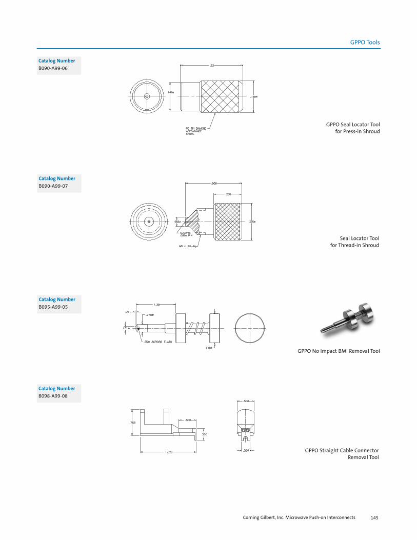
Corning Gilbert, Inc. Microwave Push-on Interconnects 145
GPPO Seal Locator Tool for Press-in Shroud
GPPO Tools
Seal Locator Toolfor Thread-in Shroud
GPPO No Impact BMI Removal Tool
Catalog Number
B090-A99-06
Catalog Number
B095-A99-05
Catalog Number
B090-A99-07
Catalog Number
B098-A99-08
GPPO Straight Cable ConnectorRemoval Tool

G3PO BMI Install/Removal Tool
Corning Gilbert, Inc. Microwave Push-on Interconnects146
GPPO Tools
Catalog Number
R095-A99-01
G3PO Tools
GPPO Cable Connector Removal Tool
GPPO Male Snap-inRemoval Tool
GPPO Female Snap-inRemoval Tool
Catalog Number
B098-A99-07
Catalog Number
9001-823-0*
Catalog Number
9001-824-0*
* For use with partnumber 0118-928-4
* For use with partnumbers 0118-958-1
and B016-B11-01
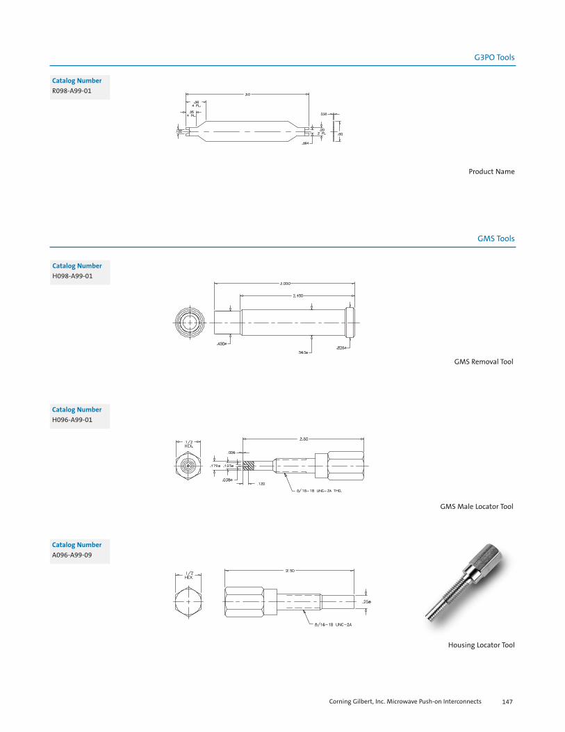
Housing Locator Tool
Corning Gilbert, Inc. Microwave Push-on Interconnects 147
Catalog Number
H098-A99-01
GMS Removal Tool
GMS Male Locator Tool
GMS Tools
Catalog Number
H096-A99-01
Product Name
Catalog Number
R098-A99-01
G3PO Tools
Catalog Number
A096-A99-09

Cable Holding Fixturefor semi-rigid Cable
Cable Holding Fixturefor .141 Cable
Shim Gauge
Corning Gilbert, Inc. Microwave Push-on Interconnects148
Catalog Number
L096-A99-10
Catalog Number
L096-A99-01 .086L096-A99-02 .047
Catalog Number
L096-A99-03L096-A99-04
Miscellaneous Tools


Corning Gilbert, Inc. Microwave Push-on Interconnects150
Appendix
Cable Assemblies
In addition to providing our worldwide customers with superior connectors and components, at Corning Gilbert, we alsooffer cable assemblies as an integrated, value-added service. Our goal is to provide our customers with the shortest leadtime and lowest priced solution for cabled Corning Gilbert connectors. To accomplish this, we:
• Specialize in single plane, semi-rigid and flexible commercial and military test application cable assemblies.
• Make custom test inspection document available upon the customer’s request.
• Provide excellent lead times.• Help you find the right connector for your system
by granting access to customized point-to-point solutions.
Please see the list below for all available Corning Gilbert connectors and its associated cable types.
Corning GilbertConnector Type Cable Types Impedance Frequency Range
GPO RG-178, RG-316, .086 Semi Rigid, 50 Ohm DC to 26.5 GHzStorm Products 120 and 421-720
GPPO .047 and .086 Semi Rigid, 50 Ohm DC to 65 GHzStorm Products 421-721
G3PO .047 Semi Rigid and .058 Flex 50 Ohm DC to 65 GHzSMA RG-316, .047, .086 and .141 Semi 50 Ohm DC to 26.5 GHz
Rigid, Storm Products 120 and 421-1110
GMS .086 and .141 Semi Rigid 50 Ohm DC to 26.5 GHzTNC .086, and .141 Semi Rigid, 50 and 75 Ohm DC to 11 GHz
Belden 9292BNC RG-59, HEC 59 50 and 75 Ohm DC to 4 GHz
N RG-59, RG-6, RG-11, RG-8, 50 and 75 Ohm DC to 11 GHzRG-223/224, .086, .141 and
.250 Semi Rigid, Storm Products 190 and 385
F RG-178, RG-179, RG-59, RG-6, 50 and 75 Ohm DC to 1 GHz is typical, RG-11, HEC 59 High Performance types
available to 3 GHz.SMB RG-316, RG-179 50 and 75 Ohm DC to 4 GHzMCX RG-316, RG-179 50 and 75 Ohm DC to 6 GHz
MMCX RG-316, RG-179 50 and 75 Ohm DC to 6 GHz

Corning Gilbert, Inc. Microwave Push-on Interconnects 151
Appendix
Test Capabilities
Corning Gilbert’s commitment to quality has made it a leader in the connector industry. Mechanical and electrical quali-ty is verified in every lot of connectors via the internal standard testing procedures. These standard tests include, but arenot limited to:
• Visual and Mechanical Inspection• Dielectric Withstanding Voltage• Hermetic Seal• Leakage• Force to Engage/Disengage• Mating Characteristics• Permeability• Insulation Resistance• VSWR
All tests listed above are standard and part of groups A and B testing, per MIL-PRF-39012. As part of our internal testprocedure, ATP-1000, they are free of charge to our customers.
Expanded testing may be obtained by requesting ATP-2000. This test includes all of ATP-1000, as well as 100%Thermal Shock testing and 100% Visual and Mechanical inspection. Corning Gilbert also has an in-house capability toperform Salt Spray and Moisture Resistance testing.
Since many Corning Gilbert connectors are utilized in military or aerospace applications, custom Test InspectionDocuments are created on a regular basis for those requiring heightened or special testing. The TIDs verify complianceto the customers’ requests and/or their submitted SCDs.
Whether you are looking for a commercial, off-the-shelf part or need extensive qualification and acceptance testing,Corning Gilbert can assure you and your customers that the parts you need are the parts you receive.
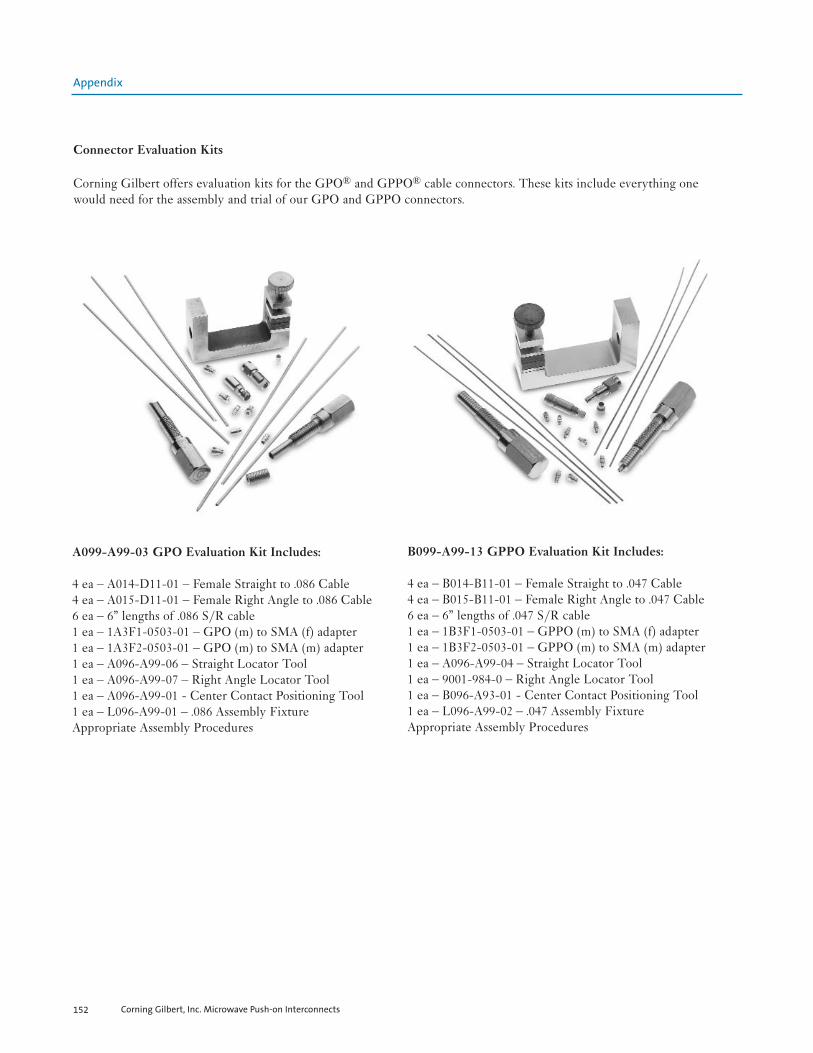
Corning Gilbert, Inc. Microwave Push-on Interconnects152
Connector Evaluation Kits
Corning Gilbert offers evaluation kits for the GPO® and GPPO® cable connectors. These kits include everything onewould need for the assembly and trial of our GPO and GPPO connectors.
A099-A99-03 GPO Evaluation Kit Includes:
4 ea – A014-D11-01 – Female Straight to .086 Cable4 ea – A015-D11-01 – Female Right Angle to .086 Cable6 ea – 6” lengths of .086 S/R cable1 ea – 1A3F1-0503-01 – GPO (m) to SMA (f) adapter1 ea – 1A3F2-0503-01 – GPO (m) to SMA (m) adapter1 ea – A096-A99-06 – Straight Locator Tool1 ea – A096-A99-07 – Right Angle Locator Tool1 ea – A096-A99-01 - Center Contact Positioning Tool1 ea – L096-A99-01 – .086 Assembly FixtureAppropriate Assembly Procedures
B099-A99-13 GPPO Evaluation Kit Includes:
4 ea – B014-B11-01 – Female Straight to .047 Cable4 ea – B015-B11-01 – Female Right Angle to .047 Cable6 ea – 6” lengths of .047 S/R cable1 ea – 1B3F1-0503-01 – GPPO (m) to SMA (f) adapter1 ea – 1B3F2-0503-01 – GPPO (m) to SMA (m) adapter1 ea – A096-A99-04 – Straight Locator Tool1 ea – 9001-984-0 – Right Angle Locator Tool1 ea – B096-A93-01 - Center Contact Positioning Tool1 ea – L096-A99-02 – .047 Assembly FixtureAppropriate Assembly Procedures
Appendix

Corning Gilbert, Inc. Microwave Push-on Interconnects 153
Adapter Matrices
The chart listed below is designed to aid in locating the appropriate adapter by application. All adapters can be found onpages 112 through 135 in this catalog.
NOTE: The "X" in the part numbers below refers to a detent-tabbed item. Replace the "X" with a "3" for a Full Detent,a "4" for a Limited Detent, or a "5" for a Smooth Bore. Not all detents are available for all adapters.
GPO/GPPO/G3PO Adapters
GPO (M) GPO (F) GPPO (M) GPPO (F) G3PO (M) G3PO (F)
1.85mm (M) 1AXM2-0509-01 1A1M2-0509-01 1BXM2-0509-01 1BXM2-0509-01 1RXM2-0509-01 1R1M2-0509-01
1.85mm (F) 1AXM1-0509-01 1A1M1-0509-01 1BXM1-0509-01 1B1M1-0509-01 1RXM1-0509-01 1R1M1-0509-01
2.4mm (M) 1AXC2-0509-01 1A1C2-0521-01 1BXC1-0503-01 1B1C2-0501-01 1RXC2-0503-01 1R1C2-0501-01
2.4mm (F) 1AXD1-0503-01 1A3C1-0503-01 1BXC1-0503-01 1B1C1-0501-01 1RXC1-0503-01 1R1C1-0501-011AXD1-0513-00
2.92mm (M) 1AXD2-0503-01 1A1D1-0501-01 1BXD2-0503-01 1B1D2-0501-01 1RXD2-0503-01 1R1D2-0501-01
2.92mm (F) 1AXD2-0503-01 1A1D1-0503-01 1BXD1-0503-01 1B1D1-0503-01 1RXD1-0503-01 1R1D1-0503-01
SMA (M) 1A3F2-0503-01 1A1F2-0503-01 1BXF2-0503-01 1B1F2-0503-01 1RXF2-0503-01 1R1F2-0503-01
SMA (F) 1AXF1-0503-01 1A1F1-0503-01 1BXF1-0503-01 1B1F1-0503-01 1RXF1-0509-01 1R1F1-0503-011AXF1-0513-03 1AXF1-0513-05 1AXF1-0523-01
GPO (M) A3AX-0539-01 1B1A3-0541-01
GPO (F) A1AX-0503-01 *A1A1-0001-XX
GPPO (M) BXBX-0523-01
BXBX-0523-02
GPPO (F) *B1B1-0001-XX
G3PO (F) R1R1-0001-01
* “XX” refers to bullet lengths. GPO and GPPO blindmate interconnect bullets are available in different lengths. Please consult the factory for information
on bullet lengths not found in this catalog.
GMS Adapters
GMS (M) GMS (F) GMS (M) GMS (F) GMS (F) GMS (F) 2-HOLE 2-HOLE BULKHEAD THREAD-IN
FLANGE FLANGEMOUNT MOUNT
SMA (M) 00218-400-3 00218-200-3 00218-202-300218-201-3
SMA (F) 00218-300-3 00218-100-3 00218-315-3 00218-103-3 00218-104-300218-301-3 00218-101-3
GPO (M) **00118-118-3- **00118-116-3-(choose detent type) (choose detent type)
**Choose Detent type (FD, LD or SB)
Appendix

Corning Gilbert, Inc. Microwave Push-on Interconnects154
Assembly Procedures
The following general assembly procedure* defines both GPO and GPPO, straight and right angle cable connectors, forboth semi rigid and flexible cable. For further assistance, or if the connector you are using is not found, please contactCorning Gilbert for specific assembly procedures.
1.0 Cable preparation:
1.1 Cut the cable to length required.1.2 For semi rigid cable, score the outer conductor with a razor blade or a semi rigid trim tool. Reference
tables I-IV, Trim Length “B”, for distance from the end of the cable to the score mark.
Note: Different trim lengths may apply, dependent upon the type of GPO connector being installed. The dielectric may be cut flush with the
outer conductor or may be stepped.
Table I: GPO Straight Table II: GPO Right Angle
Table III: GPPO Straight Table IV: GPPO Right Angle
1.3 Whether the cable is now formed per specification or remains straight, the semi rigid cable should be tempera-ture cycled to aid dielectric stability. Flexible cable does not need to be temperature cycled.
1.4 Thoroughly clean S/R cable outer conductor using fine grain sandpaper or steel wool as indicated, then wipe area clean with denatured alcohol or an equivalent cleaner.
* Applications may vary. These instructions are to be used as guidelines only. All dimensions are in inches.
Part Number Trim Length “A” Trim Length “B”A001-B83-01 N/A .085”A001-D83-01 N/A .085”A014-B11-01 N/A .090”A014-D11-01 .020” - .025” .075”A014-D11-02 N/A .060”A014-H71-01 .060” .150”
Part Number Trim Length “A” Trim Length “B”A015-B11-01 .025” .065”A015-D11-01 .025” .060”A015-D11-03 N/A .045”A015-B71-01 N/A .080”A015-F71-01 .120” .215”A015-H71-01 .250” .340”
Part Number Trim Length “A” Trim Length “B”B014-B11-01 .020” - .025” .065”B014-D11-01 N/A .055”B014-E11-01 N/A .055”B016-B11-01 .100” .180”B016-B33-01 .020” - .025” .065”B016-D33-01 N/A .040” - .050”
Part Number Trim Length “A” Trim Length “B”B015-B11-01 .025” .060”B015-B11-02 .010” - .015” .060”B015-D11-01 N/A .045”B015-D11-02 .075” - .080” .180”
Appendix

Corning Gilbert, Inc. Microwave Push-on Interconnects 155
1.5 Remove the semi rigid outer conductor with hole pliers or trim flexible cable accordingly. Do not nick the cen-ter conductor.
Note: It is recommended when working with flexible cable and solder-on connectors to make the cut on the jacket (at “B”), but do not completely
remove the jacket at this point. Rather, slide the jacket to the end of the braid and then solder dip the cable so that the braid does not expand
once the jacket is removed. When working with crimp-on connectors, a solder dip is not necessary.
1.6 Point and de-burr the center conductor.
2.0 Center contacts:
The majority of Corning Gilbert’s right angled GPO and GPPO connectors have captivated contacts. Therefore, they do not require the extra step of soldering on a center conductor. Some of these connectors include: A015-B11-01, A015-D11-01, B015-B11-01 and B015-B11-02.
2.1 If required, place the dielectric stop and center conductor onto the cable as shown. If there is no dielectric stop, place the contact flush against the dielectric.
Note: In some cases, a shim is used to create an “air gap” between the dielectric and the center contact. The connectors on this AP which require
the use of a .010” shim include: A014-D11-02, B014-E11-01 and B015-D11-02.
2.2 The following diagram supports Corning Gilbert’s standard tooling for all center contact soldering.
3.0 Solder center contact to cable inner conductor:
3.1 Tin inner conductor of cable.3.2 Place center contact in appropriate locator tool. Heat center contact and push it over inner conductor of cable to
rest firmly against the supplied dielectric stop, shim or cable dielectric. Use a minimum amount of heat, for a limited time, with a maximum contact temperature of 550º F.
3.3 Remove excess solder.
* Applications may vary. These instructions are to be used as guidelines only. All dimensions are in inches.
Appendix
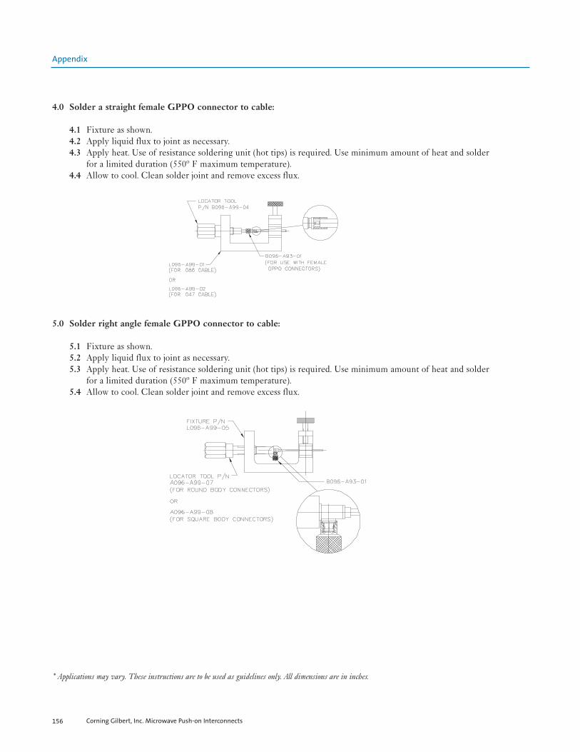
Corning Gilbert, Inc. Microwave Push-on Interconnects156
4.0 Solder a straight female GPPO connector to cable:
4.1 Fixture as shown.4.2 Apply liquid flux to joint as necessary.4.3 Apply heat. Use of resistance soldering unit (hot tips) is required. Use minimum amount of heat and solder
for a limited duration (550º F maximum temperature).4.4 Allow to cool. Clean solder joint and remove excess flux.
5.0 Solder right angle female GPPO connector to cable:
5.1 Fixture as shown.5.2 Apply liquid flux to joint as necessary.5.3 Apply heat. Use of resistance soldering unit (hot tips) is required. Use minimum amount of heat and solder
for a limited duration (550º F maximum temperature).5.4 Allow to cool. Clean solder joint and remove excess flux.
* Applications may vary. These instructions are to be used as guidelines only. All dimensions are in inches.
Appendix

Corning Gilbert, Inc. Microwave Push-on Interconnects 157
6.0 Solder a straight female GPO connector to cable.
6.1 Fixture as shown.6.2 Apply liquid flux to joint as necessary.6.3 Apply heat. Use of resistance soldering unit (hot tips) is required. Use minimum amount of heat and solder for a
limited duration (550º F maximum temperature).6.4 Allow to cool. Clean solder joint and remove excess flux.
7.0 Solder right angle female GPO contact to cable:
7.1 Install contact positioning tool A096-A99-01 on interface of connector.
7.2 Carefully insert cable into housing. Cable center conductor must engage center contact of connector. Visually inspect cable junction from rear of connector as shown. Solder cable center conductor to center contact. Removeexcess flux.
7.3 Remove connector from contact positioning tool.
* Applications may vary. These instructions are to be used as guidelines only. All dimensions are in inches.
Appendix

8.0 Solder right angle female GPO connector to cable:
8.1 Fixture as shown.8.2 Apply liquid flux to joint as necessary.8.3 Apply heat. Use of resistance soldering unit (hot tips) is required. Use minimum amount of heat and solder for a
limited duration (550º F maximum temperature).8.4 Allow to cool. Clean solder joint and remove excess flux.
9.0 Install port plug for right angle GPO and GPPO:
9.1 Orient plug as shown.9.2 Gently press plug until seated. Do no over press as damage to the unit will result.
10.0Interface dimensions:
10.1 Adherence to these assembly procedures will yield interface dimensions shown.
* Applications may vary. These instructions are to be used as guidelines only. All dimensions are in inches.
Corning Gilbert, Inc. Microwave Push-on Interconnects158
Appendix

Corning Gilbert, Inc. Microwave Push-on Interconnects 159
GPO, GPPO and G3PO Application Notes
Corning Gilbert’s push-on connector products allow users flexibility in modular and board layout (in high density situa-tions), frequency bandwidths from DC to 100 GHz and ease of mating or de-mating using female cable adapters or blindmate interconnects (bullets)—while achieving a highly reliable electro/mechanical interface. High quality and cost effec-tiveness make Corning Gilbert the push-on connector of choice.
The GPO male interface is compliant to MIL-STD-348, and it is in accordance with MIL-PRF-39012a and DESC94007/94008.
I. Materials and FinishesThe following information represents the material/plating used in the manufacturing of push-on male shrouds (soldered,braised or threaded), blind mate interconnects (bullets), straight female cable connectors, flange/bulkhead connectors anda wide assortment of adapters.
Table 1-a
Note: BeCu is the common metal used for all contacts.
Table 1-b
Table 1-c
II. MechanicalDetent: a mechanism that temporarily keeps one part in a certain position relative to that of another, and can be released by applying
force to one of the parts.
Each of the detent levels—Full Detent, Limited Detent and Smooth Bore—provide different levels of force required tomate and de-mate the connectors. The following table shows available detents, typical engagement and disengagementforces, and mating cycles for GPOs, GPPOs and G3POs.
Table 2-aEngage and Disengage Forces (All values are shown in lbs.)
Note: Corning Gilbert recommends a Full Detent when used in conjunction with a female cable connector.
Smooth Bore and a Full Detent male shroud are recommended when using a blindmate (bullet) to interface
two modules (mated together) or printed circuit board in a stacked configuration.
Material SpecificationBeCu (Beryllium Copper) ASTM B 196 and/or ASTM B 197
Brass ASTM B 36, B121, B16, B16MStainless Steel (303/304) ASTM A484/ A582 or A555/581
Kovar ASTM F15
Finishing SpecificationGold (50-100u in.) ASTM-B488 Type 1, Class 1.25
Nickel (50-100u in.) AMS-QQ-N-290
Dielectric SpecificationVirgin PTFE Flourocarbon ASTM D 1710 and ASTM D 1457Torlon (Polyamide-Imide) ASTM-600/700
PEEK ASTM D 500, 600 & 700Tefzel ASTM D-500, 600 & 700
Engage Disengage Cycles (Min)GPO GPPO G3PO GPO GPPO G3PO GPO GPPO G3PO
Full 7.0 6.5 4.2 9.0 4.5 2.2 100 100 100Limited 5.0 N/A N/A 7.0 N/A N/A 500 N/A N/A
Smooth Bore 2.0 2.5 1.2 0.5 1.5 0.9 1000 500 500
Detent
Appendix

Corning Gilbert, Inc. Microwave Push-on Interconnects160
Axial Misalignment: a distance the female interconnect can travel in an axial direction from the reference plane with minimal effect to
the VSWR response.
See Figure 1 and Table 2-b. Swept VSWR versus various axial misalignment data can be found on Charts 1, 2 & 3.
Figure 1Visual Concept of Axial MisalignmentIdeal Misaligned
Table 2-bAxial Misalignment from Reference Plane vs. VSWR for GPO, GPPO & G3PO
Chart 1GPO Interface (A1A1-0001-01) Axial Misalignment from Reference Plane vs. VSWR @ .001” Increments
Interface Axial Misalignment VSWR (Typ)Full/Limited Detent .010 max 1.10:1
Smooth Bore .018 max 1.30:1Full Detent .010 max 1.15:1
Smooth Bore .012 max 1.30:1Full Detent .008 max 1.20:1
Smooth Bore .010 max 1.35:1
GPO (26.5 GHz)
GPPO (40 GHz)
G3PO (65 GHz)
1 .00
1 .10
1 .20
1 .30
1 .40
1 .50
1 .60
1 .70
0.0
4
0.9
6
1.8
8
2.8
0
3.7
2
4.6
4
5.5
6
6.4
8
7.4
0
8.3
2
9.2
4
10
.16
11
.08
12
.00
12
.92
13
.84
14
.76
15
.68
16
.60
17
.52
18
.44
19
.36
20
.28
21
.20
22
.12
23
.04
23
.96
24
.88
25
.80
Frequency, GHz
VS
WR
Appendix

Corning Gilbert, Inc. Microwave Push-on Interconnects 161
Chart 2GPPO Interface (B1B1-0001-01)Axial Misalignment from Reference Plane vs. VSWR @ .001” Increments
Note: Surpassing the axial misalignment of .010” (+/- .005”) will affect the VSWR.
When using a male Full Detent shroud to a bullet, to a Smooth Bore male shroud, tests
show that a .018 (+/- .009”) misalignment would result in a VSWR of 1.3:1 (typical).
Radial Misalignment: the amount of radial deflection a bullet can travel without affecting mechanical performance of both the bullet
and male shroud.
See Figure 2 and Table 2-c. Swept VSWR versus radial misalignment can be found on Charts 3 & 4.
Figure 2Visual Concept of Radial MisalignmentIdeal Misaligned
Radial Misalignment and Bullet LengthWhen using a bullet between GPO/GPPO/G3PO male shrouds, the amount of radial misalignment will depend on thelength of the bullet, with respect to the male shroud. Corning Gilbert standard bullet was used for the following tests.
Table 2-cRadial Misalignment from Centerline Reference Plane vs. VSWR for GPO, GPPO & G3PO
Interface Radial Displacement VSWR (Typ)GPO +/- .010” 1.10:1
GPPO +/- .010” 1.35:1G3PO +/- .008” 1.40:1
Appendix

Corning Gilbert, Inc. Microwave Push-on Interconnects162
Chart 3GPO Interface (A1A1-0001-01)Radial Misalignment from Centerline Reference Plane vs. VSWR @ .001” Increments
Chart 4GPPO Interface (B1B1-0001-01)Radial Misalignment from Centerline Reference Plane vs. VSWR @ .001” Increments
1.00
1.10
1.20
1.30
1.40
1.50
1.60
1.70
0.0
4
0.8
4
1.6
4
2.4
4
3.2
4
4.0
4
4.8
4
5.6
4
6.4
4
7.2
4
8.0
4
8.8
4
9.6
4
10.4
4
11.2
4
12.0
4
12.8
4
13.6
4
14.4
4
15.2
4
16.0
4
16.8
4
17
.64
18.4
4
19.2
4
20.0
4
20.8
4
21.6
4
22.4
4
23.2
4
24.0
4
24.8
4
25.6
4
26.4
4
Frequency, GHz
VS
WR
1.00
1.10
1.20
1.30
1.40
1.50
1.60
1.70
0.0
4
1.9
6
3.8
8
5.8
0
7.7
2
9.6
4
11.5
6
13.4
8
15.4
0
17
.32
19.2
4
21.1
6
23.0
8
25.0
0
26.9
2
28.8
4
30.7
6
32
.68
34.6
0
36.5
2
38.4
4
40.3
6
42.2
8
44.2
0
46.1
2
48.0
4
49.9
6
51.8
8
53.8
0
55.7
2
57.6
4
59.5
6
61.4
8
63.4
0
Frequency, GHz
VS
WR
Appendix

Corning Gilbert, Inc. Microwave Push-on Interconnects 163
III. Electrical
Table 3-aGeneral Product Specifications
Chart 5Average Power Handling Ratings for GPO, GPPO & G3PO and Typical De-rating Factors for Temperature/Altitude
0
20
40
60
80
100
120
140
160
180
200
0 5 10 15 20 25 30 35 40 45
FREQUENCY (GHZ)
AV
ER
AG
E P
OW
ER
-WA
TT
S
Parameter GPO GPPO G3POInsulation Resistance (IR) 5,000 Mohms @ 500 Vdc 5,000 Mohms @ 500 Vdc 3,700 Mohms @ 250 Vdc
Dielectric Withstanding Voltage (DWV) 500 Vrms 325 Vrms 250 Vrms
RF High Pot. @ 5 MHz 325 Vrms 200 Vrms 150 VrmsCorona Level @ 70,000 ft 190 Vrms 125 Vrms 100 Vrms
Center Conductor Contact Resistance (mohms max.) 6.0 6.0 6.0Center Contact Retention
(captivated center conductor) 1.5lbs min 1.5lbs min .75 minTemperature Range
-65 to +165º C Yes Yes YesAverage Power Ratings in Watts See Chart 5 See Chart 5 See Chart 5
GPO
GPPOG3PO
Appendix

Corning Gilbert, Inc. Microwave Push-on Interconnects164
VSWR Characteristics of a Blindmate Interconnect (Bullet)
Figure 3Standard Bullet Mated Between Two Male Shrouds
Note: The bullet is bottomed out against
male shrouds. This is the ideal case.
Table 3-bBlind Mate (Bullet Mated to Male Shroud)
Chart 6GPO Blindmate Interconnect (Bullet)
Chart 7GPPO Blindmate Interconnect (Bullet)
Parameter GPO GPPO G3POImpedance (ohms) 50 50 50Frequency (GHz) 26.5 40 65
VSWR (Typ) 1.15:1 1.15:1 1.1:1 to 26.5 GHz1.25:1 to 65 GHz
1.00
1.10
1.20
1.30
1.40
1.50
1.60
1.70
1.80
1.90
2.00
0 5 10 15 20 25 30 35 40 45 50
Frequency (GHz)
VS
WR
Sept. 28, 2005GPO BMI Bullet
1.00
1.10
1.20
1.30
1.40
1.50
1.60
1.70
1.80
1.90
2.00
0 5 10 15 20 25 30 35 40 45 50
Frequency (GHz)
VS
WR
Nov. 30, 2005GPPO BMI Bullet
Appendix

Corning Gilbert, Inc. Microwave Push-on Interconnects 165
Chart 8G3PO Blindmate Interconnect (Bullet)
VSWR Characteristics of GPO, GPPO & G3PO Female Straight to Flex or Semi-rigid Cable
Figure 4Female Straight to Flex or Semi-rigid Cable
(GPO Example)
Table 3-cVSWR Performance for GPO, GPPO & G3PO Female, Straight Cable Connectors
Note: The above data was generated using two female straight connectors with a length of coax in between.
Parameter GPO GPPO G3POImpedance (ohms) 50 50 50Frequency (GHz) 26.5 40 65
VSWR (max) 1.10:1 1.10:1 to 26.5 GHz 1.10:1 to 26.5 GHz1.20:1 to 40 GHz 1.25:1 to 65 GHz
Appendix

Corning Gilbert, Inc. Microwave Push-on Interconnects166
Chart 9GPO Female Straight Connector
Chart 10GPPO Female, Straight Connector
Surface Mount GPO Connector to Microstrip Matching
Figure 5GPO Surface Mount Connector on Rogers® 4350 10mil Thick Substrate MaterialStructure Visualization
Note: This illustration shows how a GPO SMT
connector (A012-P93-01) is mounted and matched on
microstrip using Rogers® 4350 10-mil thick substrate.
0119-925-1
1.00
1.10
1.20
1.30
1.40
1.50
1.60
1.70
1.80
1.90
2.00
0 5 10 15 20 25 30 35 40 45 50
Frequency (GHz)
VS
WR
Aug. 31, 2005GPO Female to .086" S/R
0118-926-1
1.00
1.10
1.20
1.30
1.40
1.50
1.60
1.70
1.80
1.90
2.00
0 5 10 15 20 25 30 35 40 45 50
Frequency (GHz)
VS
WR
Jun. 13, 2005GPPO female straight to .047"
S/R cable
Appendix

Corning Gilbert, Inc. Microwave Push-on Interconnects 167
Figure 6GPO Microstrip Footprint
Note: Footprint of the printed circuit traces and the plated
hole positions and pre-plate diameters shown above.
Figure 7Modeled Structure (structure simplification for modeling)
Note: Shows how the GPO SMT connector is modeled for simulation
using SCT Microwave Studio® software.
Chart 11Input & Output Return Loss Results
Matched GPO™ Connector on 10 -mil Rogers® 4350 Substrate Input and Output Return Losses
-70.000
-60.000
-50.000
-40.000
-30.000
-20.000
-10.000
0.000
0.0 1.0 2.0 3.0 4.0 5.0 6.0 7.0 8.0 9.0 10.0 11.0 12.0 13.0 14.0 15.0 16.0 17.0 18.0 19.0 20.0
Frequency
dB
Appendix

Corning Gilbert, Inc. Microwave Push-on Interconnects168
Chart 12Forward & Reverse Insertion Loss Results
Note: Forward and reverse insertion losses versus frequency shown above.
Surface Mount G3PO Connector to Microstrip Matching
Figure 8Structure Visualization
Note: Mounting of a G3PO connector on Rogers 4350B microstrip with a dielectric thickness of 10 mils (0.010 inches). The dielectric constant of the substrate is 3.48± .05. The copper upper layer is assumed to be ½ ounce copper plated up to 2 ounce copper total (2.7 mils or 0.0027 inches thick).
Figure 9Structure Simplification for Modeling
Note: This simulation was simplified by setting the output to a
standard 50 ohm coaxial line. The remainder of the structure
matches the G3PO surface mount connection exactly. The reference
plane for the plots of the S parameters is set to the beginning of the
taper at the bottom of the figure.
Matched GPO™ Connector on 10 -mil Rogers® 4350 Substrate
Forward and Reverse Insertion Losses
-0.300
-0.250
-0.200
-0.150
-0.100
-0.050
0.000
0.0 1.0 2.0 3.0 4.0 5.0 6.0 7.0 8.0 9.0 10.0 11.0 12.0 13.0 14.0 15.0 16.0 17.0 18.0 19.0 20.0
Frequency
dB
Appendix
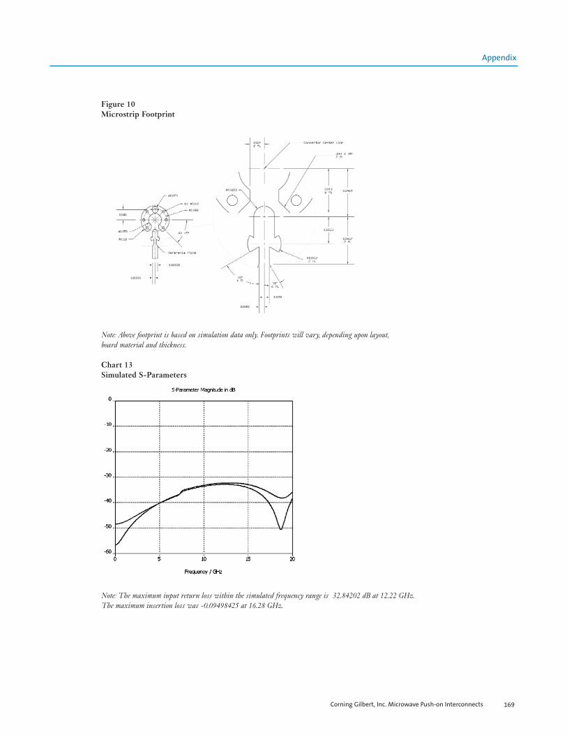
Corning Gilbert, Inc. Microwave Push-on Interconnects 169
Figure 10 Microstrip Footprint
Note: Above footprint is based on simulation data only. Footprints will vary, depending upon layout,
board material and thickness.
Chart 13Simulated S-Parameters
Note: The maximum input return loss within the simulated frequency range is 32.84202 dB at 12.22 GHz.
The maximum insertion loss was -0.09498425 at 16.28 GHz.
Appendix
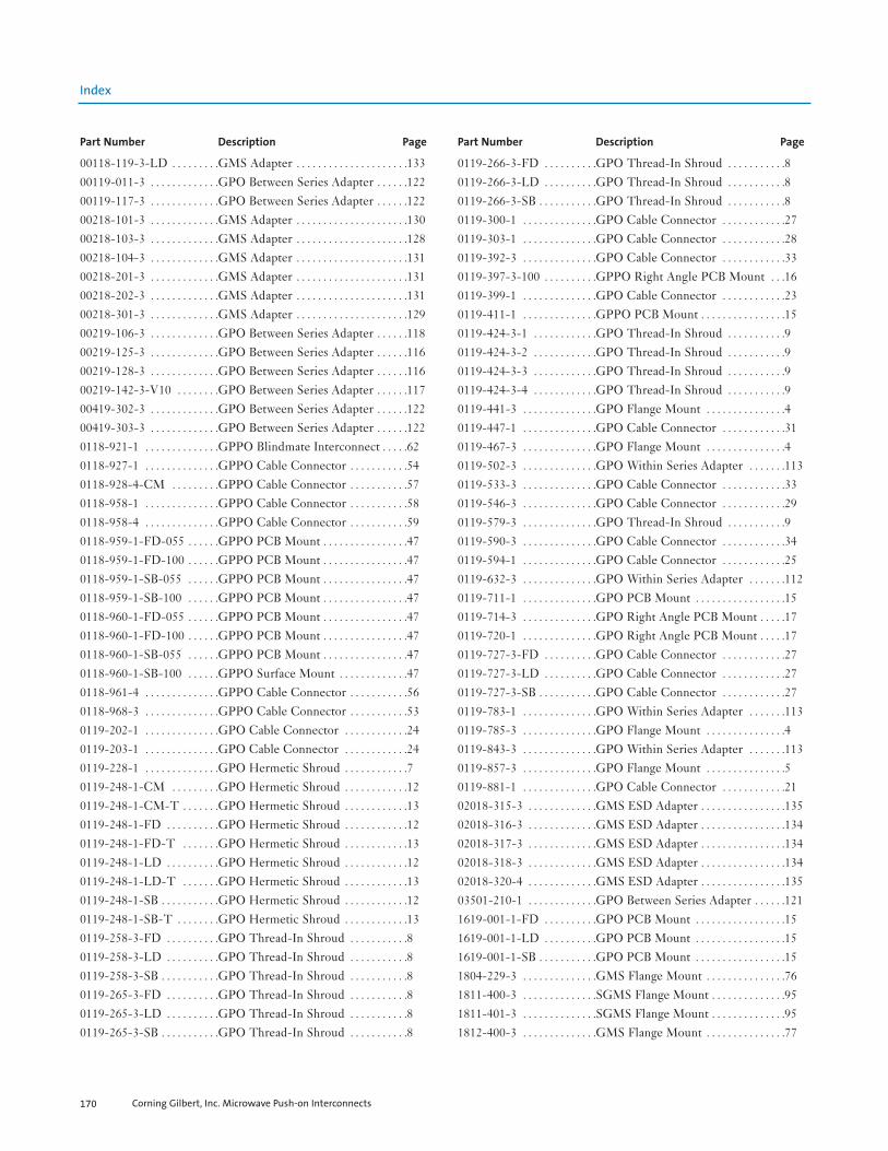
Corning Gilbert, Inc. Microwave Push-on Interconnects170
Index
00118-119-3-LD . . . . . . . . .GMS Adapter . . . . . . . . . . . . . . . . . . . . .13300119-011-3 . . . . . . . . . . . . .GPO Between Series Adapter . . . . . .12200119-117-3 . . . . . . . . . . . . .GPO Between Series Adapter . . . . . .12200218-101-3 . . . . . . . . . . . . .GMS Adapter . . . . . . . . . . . . . . . . . . . . .13000218-103-3 . . . . . . . . . . . . .GMS Adapter . . . . . . . . . . . . . . . . . . . . .12800218-104-3 . . . . . . . . . . . . .GMS Adapter . . . . . . . . . . . . . . . . . . . . .13100218-201-3 . . . . . . . . . . . . .GMS Adapter . . . . . . . . . . . . . . . . . . . . .13100218-202-3 . . . . . . . . . . . . .GMS Adapter . . . . . . . . . . . . . . . . . . . . .13100218-301-3 . . . . . . . . . . . . .GMS Adapter . . . . . . . . . . . . . . . . . . . . .12900219-106-3 . . . . . . . . . . . . .GPO Between Series Adapter . . . . . .11800219-125-3 . . . . . . . . . . . . .GPO Between Series Adapter . . . . . .11600219-128-3 . . . . . . . . . . . . .GPO Between Series Adapter . . . . . .11600219-142-3-V10 . . . . . . . .GPO Between Series Adapter . . . . . .11700419-302-3 . . . . . . . . . . . . .GPO Between Series Adapter . . . . . .12200419-303-3 . . . . . . . . . . . . .GPO Between Series Adapter . . . . . .1220118-921-1 . . . . . . . . . . . . . .GPPO Blindmate Interconnect . . . . .620118-927-1 . . . . . . . . . . . . . .GPPO Cable Connector . . . . . . . . . . .540118-928-4-CM . . . . . . . . .GPPO Cable Connector . . . . . . . . . . .570118-958-1 . . . . . . . . . . . . . .GPPO Cable Connector . . . . . . . . . . .580118-958-4 . . . . . . . . . . . . . .GPPO Cable Connector . . . . . . . . . . .590118-959-1-FD-055 . . . . . .GPPO PCB Mount . . . . . . . . . . . . . . . .470118-959-1-FD-100 . . . . . .GPPO PCB Mount . . . . . . . . . . . . . . . .470118-959-1-SB-055 . . . . . .GPPO PCB Mount . . . . . . . . . . . . . . . .470118-959-1-SB-100 . . . . . .GPPO PCB Mount . . . . . . . . . . . . . . . .470118-960-1-FD-055 . . . . . .GPPO PCB Mount . . . . . . . . . . . . . . . .470118-960-1-FD-100 . . . . . .GPPO PCB Mount . . . . . . . . . . . . . . . .470118-960-1-SB-055 . . . . . .GPPO PCB Mount . . . . . . . . . . . . . . . .470118-960-1-SB-100 . . . . . .GPPO Surface Mount . . . . . . . . . . . . .470118-961-4 . . . . . . . . . . . . . .GPPO Cable Connector . . . . . . . . . . .560118-968-3 . . . . . . . . . . . . . .GPPO Cable Connector . . . . . . . . . . .530119-202-1 . . . . . . . . . . . . . .GPO Cable Connector . . . . . . . . . . . .240119-203-1 . . . . . . . . . . . . . .GPO Cable Connector . . . . . . . . . . . .240119-228-1 . . . . . . . . . . . . . .GPO Hermetic Shroud . . . . . . . . . . . .70119-248-1-CM . . . . . . . . .GPO Hermetic Shroud . . . . . . . . . . . .120119-248-1-CM-T . . . . . . .GPO Hermetic Shroud . . . . . . . . . . . .130119-248-1-FD . . . . . . . . . .GPO Hermetic Shroud . . . . . . . . . . . .120119-248-1-FD-T . . . . . . .GPO Hermetic Shroud . . . . . . . . . . . .130119-248-1-LD . . . . . . . . . .GPO Hermetic Shroud . . . . . . . . . . . .120119-248-1-LD-T . . . . . . .GPO Hermetic Shroud . . . . . . . . . . . .130119-248-1-SB . . . . . . . . . . .GPO Hermetic Shroud . . . . . . . . . . . .120119-248-1-SB-T . . . . . . . .GPO Hermetic Shroud . . . . . . . . . . . .130119-258-3-FD . . . . . . . . . .GPO Thread-In Shroud . . . . . . . . . . .80119-258-3-LD . . . . . . . . . .GPO Thread-In Shroud . . . . . . . . . . .80119-258-3-SB . . . . . . . . . . .GPO Thread-In Shroud . . . . . . . . . . .80119-265-3-FD . . . . . . . . . .GPO Thread-In Shroud . . . . . . . . . . .80119-265-3-LD . . . . . . . . . .GPO Thread-In Shroud . . . . . . . . . . .80119-265-3-SB . . . . . . . . . . .GPO Thread-In Shroud . . . . . . . . . . .8
0119-266-3-FD . . . . . . . . . .GPO Thread-In Shroud . . . . . . . . . . .80119-266-3-LD . . . . . . . . . .GPO Thread-In Shroud . . . . . . . . . . .80119-266-3-SB . . . . . . . . . . .GPO Thread-In Shroud . . . . . . . . . . .80119-300-1 . . . . . . . . . . . . . .GPO Cable Connector . . . . . . . . . . . .270119-303-1 . . . . . . . . . . . . . .GPO Cable Connector . . . . . . . . . . . .280119-392-3 . . . . . . . . . . . . . .GPO Cable Connector . . . . . . . . . . . .330119-397-3-100 . . . . . . . . . .GPPO Right Angle PCB Mount . . .160119-399-1 . . . . . . . . . . . . . .GPO Cable Connector . . . . . . . . . . . .230119-411-1 . . . . . . . . . . . . . .GPPO PCB Mount . . . . . . . . . . . . . . . .150119-424-3-1 . . . . . . . . . . . .GPO Thread-In Shroud . . . . . . . . . . .90119-424-3-2 . . . . . . . . . . . .GPO Thread-In Shroud . . . . . . . . . . .90119-424-3-3 . . . . . . . . . . . .GPO Thread-In Shroud . . . . . . . . . . .90119-424-3-4 . . . . . . . . . . . .GPO Thread-In Shroud . . . . . . . . . . .90119-441-3 . . . . . . . . . . . . . .GPO Flange Mount . . . . . . . . . . . . . . .40119-447-1 . . . . . . . . . . . . . .GPO Cable Connector . . . . . . . . . . . .310119-467-3 . . . . . . . . . . . . . .GPO Flange Mount . . . . . . . . . . . . . . .40119-502-3 . . . . . . . . . . . . . .GPO Within Series Adapter . . . . . . .1130119-533-3 . . . . . . . . . . . . . .GPO Cable Connector . . . . . . . . . . . .330119-546-3 . . . . . . . . . . . . . .GPO Cable Connector . . . . . . . . . . . .290119-579-3 . . . . . . . . . . . . . .GPO Thread-In Shroud . . . . . . . . . . .90119-590-3 . . . . . . . . . . . . . .GPO Cable Connector . . . . . . . . . . . .340119-594-1 . . . . . . . . . . . . . .GPO Cable Connector . . . . . . . . . . . .250119-632-3 . . . . . . . . . . . . . .GPO Within Series Adapter . . . . . . .1120119-711-1 . . . . . . . . . . . . . .GPO PCB Mount . . . . . . . . . . . . . . . . .150119-714-3 . . . . . . . . . . . . . .GPO Right Angle PCB Mount . . . . .170119-720-1 . . . . . . . . . . . . . .GPO Right Angle PCB Mount . . . . .170119-727-3-FD . . . . . . . . . .GPO Cable Connector . . . . . . . . . . . .270119-727-3-LD . . . . . . . . . .GPO Cable Connector . . . . . . . . . . . .270119-727-3-SB . . . . . . . . . . .GPO Cable Connector . . . . . . . . . . . .270119-783-1 . . . . . . . . . . . . . .GPO Within Series Adapter . . . . . . .1130119-785-3 . . . . . . . . . . . . . .GPO Flange Mount . . . . . . . . . . . . . . .40119-843-3 . . . . . . . . . . . . . .GPO Within Series Adapter . . . . . . .1130119-857-3 . . . . . . . . . . . . . .GPO Flange Mount . . . . . . . . . . . . . . .50119-881-1 . . . . . . . . . . . . . .GPO Cable Connector . . . . . . . . . . . .2102018-315-3 . . . . . . . . . . . . .GMS ESD Adapter . . . . . . . . . . . . . . . .13502018-316-3 . . . . . . . . . . . . .GMS ESD Adapter . . . . . . . . . . . . . . . .13402018-317-3 . . . . . . . . . . . . .GMS ESD Adapter . . . . . . . . . . . . . . . .13402018-318-3 . . . . . . . . . . . . .GMS ESD Adapter . . . . . . . . . . . . . . . .13402018-320-4 . . . . . . . . . . . . .GMS ESD Adapter . . . . . . . . . . . . . . . .13503501-210-1 . . . . . . . . . . . . .GPO Between Series Adapter . . . . . .1211619-001-1-FD . . . . . . . . . .GPO PCB Mount . . . . . . . . . . . . . . . . .151619-001-1-LD . . . . . . . . . .GPO PCB Mount . . . . . . . . . . . . . . . . .151619-001-1-SB . . . . . . . . . . .GPO PCB Mount . . . . . . . . . . . . . . . . .151804-229-3 . . . . . . . . . . . . . .GMS Flange Mount . . . . . . . . . . . . . . .761811-400-3 . . . . . . . . . . . . . .SGMS Flange Mount . . . . . . . . . . . . . .951811-401-3 . . . . . . . . . . . . . .SGMS Flange Mount . . . . . . . . . . . . . .951812-400-3 . . . . . . . . . . . . . .GMS Flange Mount . . . . . . . . . . . . . . .77
Part Number Description Page Part Number Description Page

Corning Gilbert, Inc. Microwave Push-on Interconnects 171
Index
1815-606-3 . . . . . . . . . . . . . .GMS Cable Connector . . . . . . . . . . . .801816-203-3 . . . . . . . . . . . . . .GMS Thread-In Shroud . . . . . . . . . . .791816-204-3 . . . . . . . . . . . . . .GMS Flange Mount . . . . . . . . . . . . . . .771816-206-3 . . . . . . . . . . . . . .GMS Thread-In Shroud . . . . . . . . . . .791816-208-1 . . . . . . . . . . . . . .GMS Edge Mount . . . . . . . . . . . . . . . .801881-001-1 . . . . . . . . . . . . . .SGMS Blindmate Interconnect . . . .981890-022-1 . . . . . . . . . . . . . .GMS Cable Connector . . . . . . . . . . . .891890-023-1 . . . . . . . . . . . . . .GMS Cable Connector . . . . . . . . . . . .881890-024-1 . . . . . . . . . . . . . .GMS Cable Connector . . . . . . . . . . . .891890-025-1 . . . . . . . . . . . . . .GMS Cable Connector . . . . . . . . . . . .881A1C2-0521-01 . . . . . . . . . .GPO Between Series Adapter . . . . . .1191A1D1-0501-01 . . . . . . . . . .GPO Between Series Adapter . . . . . .1201A1D2-0501-01 . . . . . . . . . .GPO Between Series Adapter . . . . . .1201A1F2-0503-01 . . . . . . . . . .GPO Between Series Adapter . . . . . .1191A3C1-0503-01 . . . . . . . . . .GPO Between Series Adapter . . . . . .1191A3D1-0503-01 . . . . . . . . . .GPO Between Series Adapter . . . . . .1201A3D2-0503-01 . . . . . . . . . .GPO Between Series Adapter . . . . . .1201A3F1-0503-01 . . . . . . . . . .GPO Between Series Adapter . . . . . .1141A3F1-0513-02 . . . . . . . . . .GPO Between Series Adapter . . . . . .1171A3F1-0513-03 . . . . . . . . . .GPO Between Series Adapter . . . . . .1151A3F1-0513-04 . . . . . . . . . .GPO Between Series Adapter . . . . . .1171A3F1-0513-05 . . . . . . . . . .GPO Between Series Adapter . . . . . .1151A3F1-0523-01 . . . . . . . . . .GPO Between Series Adapter . . . . . .1141A3F1-0523-02 . . . . . . . . . .GPO Between Series Adapter . . . . . .1141A3F1-0523-05 . . . . . . . . . .GPO Between Series Adapter . . . . . .1151A3F2-0503-01 . . . . . . . . . .GPO Between Series Adapter . . . . . .1181A3G1-0533-01 . . . . . . . . . .GPO Between Series Adapter . . . . . .1211A3H1-0511-01 . . . . . . . . . .GMS Adapter . . . . . . . . . . . . . . . . . . . . .1331A3H1-0511-02 . . . . . . . . . .GMS Adapter . . . . . . . . . . . . . . . . . . . . .1321A3H1-0521-01 . . . . . . . . . .GMS Adapter . . . . . . . . . . . . . . . . . . . . .1321A3H2-0533-01 . . . . . . . . . .GMS Adapter . . . . . . . . . . . . . . . . . . . . .1331A4D1-0503-01 . . . . . . . . . .GPO Between Series Adapter . . . . . .1201A4D1-0513-01 . . . . . . . . . .GPO Between Series Adapter . . . . . .1211A4F1-0503-01 . . . . . . . . . .GPO Between Series Adapter . . . . . .1141A4F1-0513-03 . . . . . . . . . .GPO Between Series Adapter . . . . . .1151A4F1-0513-05 . . . . . . . . . .GPO Between Series Adapter . . . . . .1151A4F1-0523-01 . . . . . . . . . .GPO Between Series Adapter . . . . . .1141A4F1-0523-02 . . . . . . . . . .GPO Between Series Adapter . . . . . .1141A4F2-0503-01 . . . . . . . . . .GPO Between Series Adapter . . . . . .1181A4H1-0511-02 . . . . . . . . . .GMS Adapter . . . . . . . . . . . . . . . . . . . . .1321A4H1-0521-01 . . . . . . . . . .GMS Adapter . . . . . . . . . . . . . . . . . . . . .1321A5D1-0503-01 . . . . . . . . . .GPO Between Series Adapter . . . . . .1201A5D1-0513-01 . . . . . . . . . .GPO Between Series Adapter . . . . . .1211A5F1-0503-01 . . . . . . . . . .GPO Between Series Adapter . . . . . .1141A5F1-0513-02 . . . . . . . . . .GPO Between Series Adapter . . . . . .1171A5F1-0513-03 . . . . . . . . . .GPO Between Series Adapter . . . . . .1151A5F1-0513-05 . . . . . . . . . .GPO Between Series Adapter . . . . . .115
1A5F1-0523-01 . . . . . . . . . .GPO Between Series Adapter . . . . . .1141A5F1-0523-05 . . . . . . . . . .GPO Between Series Adapter . . . . . .1151A5F2-0503-01 . . . . . . . . . .GPO Between Series Adapter . . . . . .1181A5H1-0511-02 . . . . . . . . . .GMS Adapter . . . . . . . . . . . . . . . . . . . . .1321A5H1-0521-01 . . . . . . . . . .GMS Adapter . . . . . . . . . . . . . . . . . . . . .1321A6F1-0513-02 . . . . . . . . . .GPO Between Series Adapter . . . . . .1161B1A3-0541-01 . . . . . . . . . .GPPO Between Series Adapter . . . .1231B1C1-0501-01 . . . . . . . . . .GPPO Between Series Adapter . . . .1251B1C2-0501-01 . . . . . . . . . .GPPO Between Series Adapter . . . .1251B1F1-0503-01 . . . . . . . . . .GPPO Between Series Adapter . . . .1241B1F2-0503-01 . . . . . . . . . .GPPO Between Series Adapter . . . .1241B1M1-0509-01 . . . . . . . . .GPPO Between Series Adapter . . . .1261B1M2-0509-01 . . . . . . . . .GPPO Between Series Adapter . . . .1271B3C1-0503-01 . . . . . . . . . .GPPO Between Series Adapter . . . .1261B3C2-0503-01 . . . . . . . . . .GPPO Between Series Adapter . . . .1261B3F1-0503-01 . . . . . . . . . .GPPO Between Series Adapter . . . .1241B3F2-0503-01 . . . . . . . . . .GPPO Between Series Adapter . . . .1251B3M1-0509-01 . . . . . . . . .GPPO Between Series Adapter . . . .1271B3M2-0509-01 . . . . . . . . .GPPO Between Series Adapter . . . .1271B5C1-0503-01 . . . . . . . . . .GPPO Between Series Adapter . . . .1261B5F1-0503-01 . . . . . . . . . .GPPO Between Series Adapter . . . .1241B5F2-0503-01 . . . . . . . . . .GPPO Between Series Adapter . . . .1251B5M1-0509-01 . . . . . . . . .GPPO Between Series Adapter . . . .1271B5M2-0509-01 . . . . . . . . .GPPO Between Series Adapter . . . .1271F1H1-0501-01 . . . . . . . . . .GMS Adapter . . . . . . . . . . . . . . . . . . . . .1291F1H2-0503-01 . . . . . . . . . .GMS Adapter . . . . . . . . . . . . . . . . . . . . .1291F1H2-0513-01 . . . . . . . . . .GMS Adapter . . . . . . . . . . . . . . . . . . . . .1321F2H1-0501-01 . . . . . . . . . .GMS Adapter . . . . . . . . . . . . . . . . . . . . .1301F2H2-0503-01 . . . . . . . . . .GMS Adapter . . . . . . . . . . . . . . . . . . . . .1301R3F1-0509-01 . . . . . . . . . .G3PO Between Series Adapter . . . . .1281R3M1-0509-01 . . . . . . . . .G3PO Between Series Adapter . . . . .1281R5F1-0509-01 . . . . . . . . . .G3PO Between Series Adapter . . . . .1281R5M1-0509-01 . . . . . . . . .G3PO Between Series Adapter . . . . .1286804-100-2 . . . . . . . . . . . . . .SGMS Thread-In Shroud . . . . . . . . . .966804-100-3 . . . . . . . . . . . . . .SGMS Cable Connector . . . . . . . . . . .979001-823-0 . . . . . . . . . . . . . .GPPO Tool . . . . . . . . . . . . . . . . . . . . . . .1469001-824-0 . . . . . . . . . . . . . .GPPO Tool . . . . . . . . . . . . . . . . . . . . . . .146A001-A23-03 . . . . . . . . . . . .GPO PCB Mount . . . . . . . . . . . . . . . . .3A001-A23-04 . . . . . . . . . . . .GPO PCB Mount . . . . . . . . . . . . . . . . .3A001-A23-07 . . . . . . . . . . . .GPO PCB Mount . . . . . . . . . . . . . . . . .3A001-A24-03 . . . . . . . . . . . .GPO PCB Mount . . . . . . . . . . . . . . . . .3A001-A24-04 . . . . . . . . . . . .GPO PCB Mount . . . . . . . . . . . . . . . . .3A001-A24-07 . . . . . . . . . . . .GPO PCB Mount . . . . . . . . . . . . . . . . .3A001-A25-03 . . . . . . . . . . . .GPO PCB Mount . . . . . . . . . . . . . . . . .3A001-A25-04 . . . . . . . . . . . .GPO PCB Mount . . . . . . . . . . . . . . . . .3A001-A25-07 . . . . . . . . . . . .GPO PCB Mount . . . . . . . . . . . . . . . . .3A001-B83-01 . . . . . . . . . . . .GPO Cable Connector . . . . . . . . . . . .21
Part Number Description Page Part Number Description Page

Corning Gilbert, Inc. Microwave Push-on Interconnects172
Index
A001-B83-02 . . . . . . . . . . . .GPO Cable Connector . . . . . . . . . . . .21A001-B84-01 . . . . . . . . . . . .GPO Cable Connector . . . . . . . . . . . .21A001-B84-02 . . . . . . . . . . . .GPO Cable Connector . . . . . . . . . . . .21A001-B85-01 . . . . . . . . . . . .GPO Cable Connector . . . . . . . . . . . .21A001-B85-02 . . . . . . . . . . . .GPO Cable Connector . . . . . . . . . . . .21A001-D83-01 . . . . . . . . . . . .GPO Cable Connector . . . . . . . . . . . .22A001-D83-02 . . . . . . . . . . . .GPO Cable Connector . . . . . . . . . . . .22A001-D84-01 . . . . . . . . . . . .GPO Cable Connector . . . . . . . . . . . .22A001-D84-02 . . . . . . . . . . . .GPO Cable Connector . . . . . . . . . . . .22A001-D85-01 . . . . . . . . . . . .GPO Cable Connector . . . . . . . . . . . .22A001-D85-02 . . . . . . . . . . . .GPO Cable Connector . . . . . . . . . . . .22A001-N33-02 . . . . . . . . . . . .GPO Flange Mount . . . . . . . . . . . . . . .3A001-N33-05 . . . . . . . . . . . .GPO Flange Mount . . . . . . . . . . . . . . .3A001-N34-02 . . . . . . . . . . . .GPO Flange Mount . . . . . . . . . . . . . . .3A001-N34-05 . . . . . . . . . . . .GPO Flange Mount . . . . . . . . . . . . . . .3A001-N35-02 . . . . . . . . . . . .GPO Flange Mount . . . . . . . . . . . . . . .3A001-N35-05 . . . . . . . . . . . .GPO Flange Mount . . . . . . . . . . . . . . .3A003-A23-01 . . . . . . . . . . . .GPO Thread-In Shroud . . . . . . . . . . .5A003-A24-01 . . . . . . . . . . . .GPO Thread-In Shroud . . . . . . . . . . .5A003-A25-01 . . . . . . . . . . . .GPO Thread-In Shroud . . . . . . . . . . .5A003-A27-01 . . . . . . . . . . . .GPO Thread-In Shroud . . . . . . . . . . .5A003-L11-01 . . . . . . . . . . . .GPO Thread-In Shroud . . . . . . . . . . .6A003-L33-01 . . . . . . . . . . . .GPO Thread-In Shroud . . . . . . . . . . .6A003-L33-02 . . . . . . . . . . . .GPO Thread-In Shroud . . . . . . . . . . .6A003-L34-01 . . . . . . . . . . . .GPO Thread-In Shroud . . . . . . . . . . .6A003-L34-02 . . . . . . . . . . . .GPO Thread-In Shroud . . . . . . . . . . .6A003-L35-01 . . . . . . . . . . . .GPO Thread-In Shroud . . . . . . . . . . .6A003-L35-02 . . . . . . . . . . . .GPO Thread-In Shroud . . . . . . . . . . .6A003-N33-01 . . . . . . . . . . . .GPO Thread-In Shroud . . . . . . . . . . .7A003-N33-02 . . . . . . . . . . . .GPO Thread-In Shroud . . . . . . . . . . .7A003-N34-01 . . . . . . . . . . . .GPO Thread-In Shroud . . . . . . . . . . .7A003-N34-02 . . . . . . . . . . . .GPO Thread-In Shroud . . . . . . . . . . .7A003-N35-01 . . . . . . . . . . . .GPO Thread-In Shroud . . . . . . . . . . .7A003-N35-02 . . . . . . . . . . . .GPO Thread-In Shroud . . . . . . . . . . .7A005-A23-01 . . . . . . . . . . . .GPO Press-In Shroud . . . . . . . . . . . . .9A005-A23-02 . . . . . . . . . . . .GPO Press-In Shroud . . . . . . . . . . . . .9A005-A24-01 . . . . . . . . . . . .GPO Press-In Shroud . . . . . . . . . . . . .9A005-A24-02 . . . . . . . . . . . .GPO Press-In Shroud . . . . . . . . . . . . .9A005-A25-01 . . . . . . . . . . . .GPO Press-In Shroud . . . . . . . . . . . . .9A005-A25-02 . . . . . . . . . . . .GPO Press-In Shroud . . . . . . . . . . . . .9A005-L34-01 . . . . . . . . . . . .GPO Press-In Shroud . . . . . . . . . . . . .10A005-L35-01 . . . . . . . . . . . .GPO Press-In Shroud . . . . . . . . . . . . .10A006-N33-02 . . . . . . . . . . . .GPO Press-In Shroud . . . . . . . . . . . . .10A007-L43-01-TAB-X . . . .GPO Hermetic Shroud . . . . . . . . . . . .11A007-L43-02-TAB-X . . . .GPO Hermetic Shroud . . . . . . . . . . . .11A007-L43-03-TAB-X . . . .GPO Hermetic Shroud . . . . . . . . . . . .11A007-L43-04-TAB-X . . . .GPO Hermetic Shroud . . . . . . . . . . . .12
A007-L43-14 . . . . . . . . . . . .GPO Hermetic Shroud . . . . . . . . . . . .12A007-L44-01-TAB-X . . . .GPO Hermetic Shroud . . . . . . . . . . . .11A007-L44-02-TAB-X . . . .GPO Hermetic Shroud . . . . . . . . . . . .11A007-L44-03-TAB-X . . . .GPO Hermetic Shroud . . . . . . . . . . . .11A007-L44-04-TAB-X . . . .GPO Hermetic Shroud . . . . . . . . . . . .12A007-L45-01-TAB-X . . . .GPO Hermetic Shroud . . . . . . . . . . . .11A007-L45-02-TAB-X . . . .GPO Hermetic Shroud . . . . . . . . . . . .11A007-L45-03-TAB-X . . . .GPO Hermetic Shroud . . . . . . . . . . . .11A007-L45-04-TAB-X . . . .GPO Hermetic Shroud . . . . . . . . . . . .12A008-L13-03 . . . . . . . . . . . .GPO PCB Mount . . . . . . . . . . . . . . . . .13A008-L14-03 . . . . . . . . . . . .GPO PCB Mount . . . . . . . . . . . . . . . . .13A008-L15-03 . . . . . . . . . . . .GPO PCB Mount . . . . . . . . . . . . . . . . .13A008-L33-01 . . . . . . . . . . . .GPO PCB Mount . . . . . . . . . . . . . . . . .13A008-L33-02 . . . . . . . . . . . .GPO PCB Mount . . . . . . . . . . . . . . . . .13A008-L33-05 . . . . . . . . . . . .GPO PCB Mount . . . . . . . . . . . . . . . . .14A008-L33-06 . . . . . . . . . . . .GPO PCB Mount . . . . . . . . . . . . . . . . .14A008-L34-01 . . . . . . . . . . . .GPO PCB Mount . . . . . . . . . . . . . . . . .13A008-L34-02 . . . . . . . . . . . .GPO PCB Mount . . . . . . . . . . . . . . . . .13A008-L34-05 . . . . . . . . . . . .GPO PCB Mount . . . . . . . . . . . . . . . . .14A008-L35-01 . . . . . . . . . . . .GPO PCB Mount . . . . . . . . . . . . . . . . .13A008-L35-02 . . . . . . . . . . . .GPO PCB Mount . . . . . . . . . . . . . . . . .13A008-L35-05 . . . . . . . . . . . .GPO PCB Mount . . . . . . . . . . . . . . . . .14A008-P33-01 . . . . . . . . . . . .GPO PCB Mount . . . . . . . . . . . . . . . . .14A008-P34-01 . . . . . . . . . . . .GPO PCB Mount . . . . . . . . . . . . . . . . .14A008-P35-01 . . . . . . . . . . . .GPO PCB Mount . . . . . . . . . . . . . . . . .14A009-P33-01 . . . . . . . . . . . .GPO Right Angle PCB Mount . . . . .16A009-P33-03 . . . . . . . . . . . .GPO Right Angle PCB Mount . . . . .16A009-P34-01 . . . . . . . . . . . .GPO Right Angle PCB Mount . . . . .16A009-P34-03 . . . . . . . . . . . .GPO Right Angle PCB Mount . . . . .16A009-P35-01 . . . . . . . . . . . .GPO Right Angle PCB Mount . . . . .16A009-P35-03 . . . . . . . . . . . .GPO Right Angle PCB Mount . . . . .16A010-L13-02 . . . . . . . . . . . .GPO Edge Mount . . . . . . . . . . . . . . . . .17A010-L14-02 . . . . . . . . . . . .GPO Edge Mount . . . . . . . . . . . . . . . . .17A010-L15-02 . . . . . . . . . . . .GPO Edge Mount . . . . . . . . . . . . . . . . .17A010-L33-01 . . . . . . . . . . . .GPO Edge Mount . . . . . . . . . . . . . . . . .18A010-L33-02 . . . . . . . . . . . .GPO Edge Mount . . . . . . . . . . . . . . . . .18A010-L33-03 . . . . . . . . . . . .GPO Edge Mount . . . . . . . . . . . . . . . . .18A010-L33-04 . . . . . . . . . . . .GPO Edge Mount . . . . . . . . . . . . . . . . .18A010-L34-01 . . . . . . . . . . . .GPO Edge Mount . . . . . . . . . . . . . . . . .18A010-L34-02 . . . . . . . . . . . .GPO Edge Mount . . . . . . . . . . . . . . . . .18A010-L34-03 . . . . . . . . . . . .GPO Edge Mount . . . . . . . . . . . . . . . . .18A010-L34-04 . . . . . . . . . . . .GPO Edge Mount . . . . . . . . . . . . . . . . .18A010-L35-01 . . . . . . . . . . . .GPO Edge Mount . . . . . . . . . . . . . . . . .18A010-L35-02 . . . . . . . . . . . .GPO Edge Mount . . . . . . . . . . . . . . . . .18A010-L35-03 . . . . . . . . . . . .GPO Edge Mount . . . . . . . . . . . . . . . . .18A010-L35-04 . . . . . . . . . . . .GPO Edge Mount . . . . . . . . . . . . . . . . .18A012-A93-01 . . . . . . . . . . . .GPO Surface Mount . . . . . . . . . . . . . .19
Part Number Description Page Part Number Description Page

Corning Gilbert, Inc. Microwave Push-on Interconnects 173
Index
A012-A94-01 . . . . . . . . . . . .GPO Surface Mount . . . . . . . . . . . . . .19A012-A95-01 . . . . . . . . . . . .GPO Surface Mount . . . . . . . . . . . . . .19A012-A97-01 . . . . . . . . . . . .GPO Surface Mount . . . . . . . . . . . . . .19A012-A97-02 . . . . . . . . . . . .GPO Surface Mount . . . . . . . . . . . . . .19A012-L76-03 . . . . . . . . . . . .GPO Surface Mount . . . . . . . . . . . . . .19A012-L96-01 . . . . . . . . . . . .GPO Surface Mount . . . . . . . . . . . . . .20A012-P93-01 . . . . . . . . . . . .GPO Surface Mount . . . . . . . . . . . . . .20A012-P93-04 . . . . . . . . . . . .GPO Surface Mount . . . . . . . . . . . . . .20A012-P94-01 . . . . . . . . . . . .GPO Surface Mount . . . . . . . . . . . . . .20A012-P94-04 . . . . . . . . . . . .GPO Surface Mount . . . . . . . . . . . . . .20A012-P95-01 . . . . . . . . . . . .GPO Surface Mount . . . . . . . . . . . . . .20A012-P95-04 . . . . . . . . . . . .GPO Surface Mount . . . . . . . . . . . . . .20A014-B11-01 . . . . . . . . . . . .GPO Cable Connector . . . . . . . . . . . .21A014-D11-01 . . . . . . . . . . . .GPO Cable Connector . . . . . . . . . . . .22A014-D11-02 . . . . . . . . . . . .GPO Cable Connector . . . . . . . . . . . .22A014-F71-01 . . . . . . . . . . . .GPO Cable Connector . . . . . . . . . . . .23A014-H71-01 . . . . . . . . . . . .GPO Cable Connector . . . . . . . . . . . .23A014-K11-01 . . . . . . . . . . . .GPO Cable Connector . . . . . . . . . . . .24A015-B11-01 . . . . . . . . . . . .GPO Cable Connector . . . . . . . . . . . .25A015-B11-02 . . . . . . . . . . . .GPO Cable Connector . . . . . . . . . . . .25A015-B71-01 . . . . . . . . . . . .GPO Cable Connector . . . . . . . . . . . .26A015-B71-03 . . . . . . . . . . . .GPO Cable Connector . . . . . . . . . . . .26A015-D11-01 . . . . . . . . . . . .GPO Cable Connector . . . . . . . . . . . .26A015-D11-03 . . . . . . . . . . . .GPO Cable Connector . . . . . . . . . . . .27A015-F71-01 . . . . . . . . . . . .GPO Cable Connector . . . . . . . . . . . .28A015-H71-01 . . . . . . . . . . . .GPO Cable Connector . . . . . . . . . . . .28A016-B83-01 . . . . . . . . . . . .GPO Cable Connector . . . . . . . . . . . .29A016-B84-01 . . . . . . . . . . . .GPO Cable Connector . . . . . . . . . . . .29A016-B86-01 . . . . . . . . . . . .GPO Cable Connector . . . . . . . . . . . .29A016-D53-01 . . . . . . . . . . . .GPO Cable Connector . . . . . . . . . . . .29A016-D54-01 . . . . . . . . . . . .GPO Cable Connector . . . . . . . . . . . .29A016-D55-01 . . . . . . . . . . . .GPO Cable Connector . . . . . . . . . . . .29A016-D73-03 . . . . . . . . . . . .GPO Cable Connector . . . . . . . . . . . .30A016-D74-03 . . . . . . . . . . . .GPO Cable Connector . . . . . . . . . . . .30A016-D76-03 . . . . . . . . . . . .GPO Cable Connector . . . . . . . . . . . .30A016-D83-01 . . . . . . . . . . . .GPO Cable Connector . . . . . . . . . . . .30A016-D83-02 . . . . . . . . . . . .GPO Cable Connector . . . . . . . . . . . .30A016-D84-01 . . . . . . . . . . . .GPO Cable Connector . . . . . . . . . . . .30A016-D86-01 . . . . . . . . . . . .GPO Cable Connector . . . . . . . . . . . .30A016-D87-01 . . . . . . . . . . . .GPO Cable Connector . . . . . . . . . . . .31A016-G86-01 . . . . . . . . . . . .GPO Cable Connector . . . . . . . . . . . .31A016-H83-01 . . . . . . . . . . . .GPO Cable Connector . . . . . . . . . . . .32A016-H84-01 . . . . . . . . . . . .GPO Cable Connector . . . . . . . . . . . .32A016-H85-01 . . . . . . . . . . . .GPO Cable Connector . . . . . . . . . . . .32A018-B71-01 . . . . . . . . . . . .GPO Cable Connector . . . . . . . . . . . .32A018-B71-02 . . . . . . . . . . . .GPO Cable Connector . . . . . . . . . . . .32A018-D11-01 . . . . . . . . . . . .GPO Cable Connector . . . . . . . . . . . .32
A018-F71-01 . . . . . . . . . . . .GPO Cable Connector . . . . . . . . . . . .33A033-B93-02-4 . . . . . . . . . .GPO Multiposition Block . . . . . . . . .100A033-D53-01 . . . . . . . . . . . .GPO Multiposition Block . . . . . . . . .101A036-P95-01-4 . . . . . . . . . .GPO Multiposition Block . . . . . . . . .100A055-A11-01 . . . . . . . . . . . .GPO Load . . . . . . . . . . . . . . . . . . . . . . . .34A055-A11-02 . . . . . . . . . . . .GPO Load . . . . . . . . . . . . . . . . . . . . . . . .34A055-A14-01 . . . . . . . . . . . .GPO Load . . . . . . . . . . . . . . . . . . . . . . . .34A055-A14-02 . . . . . . . . . . . .GPO Load . . . . . . . . . . . . . . . . . . . . . . . .34A055-A15-01 . . . . . . . . . . . .GPO Load . . . . . . . . . . . . . . . . . . . . . . . .34A055-A15-02 . . . . . . . . . . . .GPO Load . . . . . . . . . . . . . . . . . . . . . . . .34A090-A99-01 . . . . . . . . . . . .GPO Tool . . . . . . . . . . . . . . . . . . . . . . . .138A090-A99-03 . . . . . . . . . . . .GPO Tool . . . . . . . . . . . . . . . . . . . . . . . .138A090-A99-07 . . . . . . . . . . . .GPO Tool . . . . . . . . . . . . . . . . . . . . . . . .138A090-A99-09 . . . . . . . . . . . .GPO Tool . . . . . . . . . . . . . . . . . . . . . . . .138A090-A99-10 . . . . . . . . . . . .GPO Tool . . . . . . . . . . . . . . . . . . . . . . . .139A090-A99-11 . . . . . . . . . . . .GPO Tool . . . . . . . . . . . . . . . . . . . . . . . .139A093-A99-01 . . . . . . . . . . . .GPO Tool . . . . . . . . . . . . . . . . . . . . . . . .142A095-A99-03 . . . . . . . . . . . .GPO Tool . . . . . . . . . . . . . . . . . . . . . . . .141A096-A99-01 . . . . . . . . . . . .GPO Tool . . . . . . . . . . . . . . . . . . . . . . . .139A096-A99-02 . . . . . . . . . . . .GPO Tool . . . . . . . . . . . . . . . . . . . . . . . .139A096-A99-04 . . . . . . . . . . . .GPO Tool . . . . . . . . . . . . . . . . . . . . . . . .140A096-A99-06 . . . . . . . . . . . .GPO Tool . . . . . . . . . . . . . . . . . . . . . . . .140A096-A99-07 . . . . . . . . . . . .GPO Tool . . . . . . . . . . . . . . . . . . . . . . . .140A096-A99-08 . . . . . . . . . . . .GPO Tool . . . . . . . . . . . . . . . . . . . . . . . .140A096-A99-09 . . . . . . . . . . . .GPO & GMS Tool . . . . . . . . . . .141&147A098-A98-08 . . . . . . . . . . . .GPO Tool . . . . . . . . . . . . . . . . . . . . . . . .141A098-A99-01 . . . . . . . . . . . .GPO Tool . . . . . . . . . . . . . . . . . . . . . . . .142A098-A99-02 . . . . . . . . . . . .GPO Tool . . . . . . . . . . . . . . . . . . . . . . . .142A098-A99-03 . . . . . . . . . . . .GPO Tool . . . . . . . . . . . . . . . . . . . . . . . .142A098-A99-04 . . . . . . . . . . . .GPO Tool . . . . . . . . . . . . . . . . . . . . . . . .141A098-A99-05 . . . . . . . . . . . .GPO Tool . . . . . . . . . . . . . . . . . . . . . . . .143A098-A99-10 . . . . . . . . . . . .GPO Tool . . . . . . . . . . . . . . . . . . . . . . . .143A1A1-0001-01 . . . . . . . . . . .GPO Blindmate Interconnect . . . . . .35A1A1-0001-02 . . . . . . . . . . .GPO Blindmate Interconnect . . . . . .35A1A1-0001-03 . . . . . . . . . . .GPO Blindmate Interconnect . . . . . .35A1A1-0001-09 . . . . . . . . . . .GPO Blindmate Interconnect . . . . . .36A1A1-0001-15 . . . . . . . . . . .GPO Blindmate Interconnect . . . . . .36A1A1-0001-24 . . . . . . . . . . .GPO Blindmate Interconnect . . . . . .37A1A1-0547-01 . . . . . . . . . . .GPO Blindmate Interconnect . . . . . .37A1A3-0503-01 . . . . . . . . . . .GPO Within Series Adapter . . . . . . .112A1A4-0503-01 . . . . . . . . . . .GPO Within Series Adapter . . . . . . .112A1A5-0503-01 . . . . . . . . . . .GPO Within Series Adapter . . . . . . .112A3A3-0539-01 . . . . . . . . . . .GPO Within Series Adapter . . . . . . .112A3A6-0539-01 . . . . . . . . . . .GPO Within Series Adapter . . . . . . .112B001-A23-01 . . . . . . . . . . . .GPPO Flange Mount . . . . . . . . . . . . . .41B001-A23-02 . . . . . . . . . . . .GPPO Flange Mount . . . . . . . . . . . . . .41B001-A25-01 . . . . . . . . . . . .GPPO Flange Mount . . . . . . . . . . . . . .41
Part Number Description Page Part Number Description Page

Corning Gilbert, Inc. Microwave Push-on Interconnects174
B001-A25-02 . . . . . . . . . . . .GPPO Flange Mount . . . . . . . . . . . . . .41B001-D33-01 . . . . . . . . . . . .GPPO Cable Connector . . . . . . . . . . .59B001-D35-01 . . . . . . . . . . . .GPPO Cable Connector . . . . . . . . . . .59B001-K33-01 . . . . . . . . . . . .GPPO Cable Connector . . . . . . . . . . .59B001-K35-01 . . . . . . . . . . . .GPPO Cable Connector . . . . . . . . . . .59B001-N33-01 . . . . . . . . . . . .GPPO Flange Mount . . . . . . . . . . . . . .41B001-N35-01 . . . . . . . . . . . .GPPO Flange Mount . . . . . . . . . . . . . .41B003-A23-01 . . . . . . . . . . . .GPPO Thread-In Shroud . . . . . . . . . .41B003-A25-01 . . . . . . . . . . . .GPPO Thread-In Shroud . . . . . . . . . .41B003-L33-01 . . . . . . . . . . . .GPPO Thread-In Shroud . . . . . . . . . .42B003-L33-02 . . . . . . . . . . . .GPPO Thread-In Shroud . . . . . . . . . .42B003-L33-03 . . . . . . . . . . . .GPPO Thread-In Shroud . . . . . . . . . .42B003-L33-05 . . . . . . . . . . . .GPPO Thread-In Shroud . . . . . . . . . .42B003-L33-06 . . . . . . . . . . . .GPPO Thread-In Shroud . . . . . . . . . .43B003-L35-01 . . . . . . . . . . . .GPPO Thread-In Shroud . . . . . . . . . .42B003-L35-02 . . . . . . . . . . . .GPPO Thread-In Shroud . . . . . . . . . .42B003-L35-03 . . . . . . . . . . . .GPPO Thread-In Shroud . . . . . . . . . .42B003-L35-05 . . . . . . . . . . . .GPPO Thread-In Shroud . . . . . . . . . .42B003-L35-06 . . . . . . . . . . . .GPPO Thread-In Shroud . . . . . . . . . .43B003-N33-01 . . . . . . . . . . . .GPPO Thread-In Shroud . . . . . . . . . .43B003-N33-02 . . . . . . . . . . . .GPPO Thread-In Shroud . . . . . . . . . .43B003-N35-01 . . . . . . . . . . . .GPPO Thread-In Shroud . . . . . . . . . .43B003-N35-02 . . . . . . . . . . . .GPPO Thread-In Shroud . . . . . . . . . .43B007-L43-03 . . . . . . . . . . . .GPPO Hermetic Shroud . . . . . . . . . .44B007-L45-01 . . . . . . . . . . . .GPPO Hermetic Shroud . . . . . . . . . .45B007-L45-01-T . . . . . . . . . .GPPO Hermetic Shroud . . . . . . . . . .45B007-L45-02 . . . . . . . . . . . .GPPO Multiposition Block . . . . . . . .101B007-L45-02T . . . . . . . . . . .GPPO Multiposition Block . . . . . . . .101B007-L45-04-TAB . . . . . . .GPPO Multiposition Block . . . . . . . .102B007-L45-06 . . . . . . . . . . . .GPPO Hermetic Shroud . . . . . . . . . .45B007-M43-01-TAB-X . . . .GPPO Hermetic Shroud . . . . . . . . . .46B007-M45-01-TAB-X . . . .GPPO Hermetic Shroud . . . . . . . . . .46B007-M46-01-TAB-X . . . .GPPO Hermetic Shroud . . . . . . . . . .46B008-L13-01 . . . . . . . . . . . .GPPO PCB Mount . . . . . . . . . . . . . . . .46B008-L13-05 . . . . . . . . . . . .GPPO Multiposition Block . . . . . . . .106B008-L15-01 . . . . . . . . . . . .GPPO PCB Mount . . . . . . . . . . . . . . . .46B008-P33-01 . . . . . . . . . . . . .GPPO PCB Mount . . . . . . . . . . . . . . . .47B008-P35-01 . . . . . . . . . . . . .GPPO PCB Mount . . . . . . . . . . . . . . . .47B009-P33-01 . . . . . . . . . . . . .GPPO PCB Mount . . . . . . . . . . . . . . . .48B009-P33-02 . . . . . . . . . . . . .GPPO PCB Mount . . . . . . . . . . . . . . . .48B009-P35-01 . . . . . . . . . . . . .GPPO PCB Mount . . . . . . . . . . . . . . . .48B009-P35-02 . . . . . . . . . . . . .GPPO PCB Mount . . . . . . . . . . . . . . . .48B010-L13-01 . . . . . . . . . . . .GPPO Edge Mount . . . . . . . . . . . . . . .48B010-L13-02 . . . . . . . . . . . .GPPO Edge Mount . . . . . . . . . . . . . . .49B010-L15-01 . . . . . . . . . . . .GPPO Edge Mount . . . . . . . . . . . . . . .48B010-L15-02 . . . . . . . . . . . .GPPO Edge Mount . . . . . . . . . . . . . . .49B010-L33-03 . . . . . . . . . . . .GPPO Edge Mount . . . . . . . . . . . . . . .49
B010-L33-04 . . . . . . . . . . . .GPPO Edge Mount . . . . . . . . . . . . . . .49B010-L35-03 . . . . . . . . . . . .GPPO Edge Mount . . . . . . . . . . . . . . .49B010-L35-04 . . . . . . . . . . . .GPPO Edge Mount . . . . . . . . . . . . . . .49B010-L83-01 . . . . . . . . . . . .GPPO Edge Mount . . . . . . . . . . . . . . .50B010-L83-02 . . . . . . . . . . . .GPPO Edge Mount . . . . . . . . . . . . . . .50B010-L85-01 . . . . . . . . . . . .GPPO Edge Mount . . . . . . . . . . . . . . .50B010-L85-02 . . . . . . . . . . . .GPPO Edge Mount . . . . . . . . . . . . . . .50B011-A93-01 . . . . . . . . . . . .GPPO Multiposition Block . . . . . . . .105B011-A95-13 . . . . . . . . . . . .GPPO Multiposition Block . . . . . . . .105B012-L13-01 . . . . . . . . . . . .GPPO Surface Mount . . . . . . . . . . . . .51B012-L13-02 . . . . . . . . . . . .GPPO Surface Mount . . . . . . . . . . . . .51B012-L13-03 . . . . . . . . . . . .GPPO Surface Mount . . . . . . . . . . . . .51B012-L13-04 . . . . . . . . . . . .GPPO Surface Mount . . . . . . . . . . . . .51B012-L15-01 . . . . . . . . . . . .GPPO Surface Mount . . . . . . . . . . . . .51B012-L15-02 . . . . . . . . . . . .GPPO Surface Mount . . . . . . . . . . . . .51B012-L15-03 . . . . . . . . . . . .GPPO Surface Mount . . . . . . . . . . . . .51B012-L15-04 . . . . . . . . . . . .GPPO Surface Mount . . . . . . . . . . . . .51B012-P93-01 . . . . . . . . . . . . .GPPO Surface Mount . . . . . . . . . . . . .51B012-P93-02 . . . . . . . . . . . . .GPPO Surface Mount . . . . . . . . . . . . .51B012-P95-01 . . . . . . . . . . . . .GPPO Surface Mount . . . . . . . . . . . . .51B012-P95-02 . . . . . . . . . . . . .GPPO Surface Mount . . . . . . . . . . . . .51B013-L93-01 . . . . . . . . . . . .GPPO Surface Mount . . . . . . . . . . . . .52B013-L95-01 . . . . . . . . . . . .GPPO Surface Mount . . . . . . . . . . . . .52B014-B11-01 . . . . . . . . . . . .GPPO Cable Connector . . . . . . . . . . .52B014-D11-01 . . . . . . . . . . . .GPPO Cable Connector . . . . . . . . . . .52B014-K11-01 . . . . . . . . . . . .GPPO Cable Connector . . . . . . . . . . .53B015-B11-01 . . . . . . . . . . . .GPPO Cable Connector . . . . . . . . . . .53B015-B11-02 . . . . . . . . . . . .GPPO Cable Connector . . . . . . . . . . .54B015-B11-04 . . . . . . . . . . . .GPPO Cable Connector . . . . . . . . . . .54B015-D11-01 . . . . . . . . . . . .GPPO Cable Connector . . . . . . . . . . .55B015-D11-02 . . . . . . . . . . . .GPPO Cable Connector . . . . . . . . . . .55B016-B11-01 . . . . . . . . . . . .GPPO Cable Connector . . . . . . . . . . .58B016-B33-01 . . . . . . . . . . . .GPPO Cable Connector . . . . . . . . . . .55B016-B33-02 . . . . . . . . . . . .GPPO Cable Connector . . . . . . . . . . .56B016-B35-01 . . . . . . . . . . . .GPPO Cable Connector . . . . . . . . . . .55B016-B35-02 . . . . . . . . . . . .GPPO Cable Connector . . . . . . . . . . .56B016-D33-01 . . . . . . . . . . . .GPPO Cable Connector . . . . . . . . . . .56B016-D33-02 . . . . . . . . . . . .GPPO Cable Connector . . . . . . . . . . .57B016-D35-01 . . . . . . . . . . . .GPPO Cable Connector . . . . . . . . . . .56B016-D35-02 . . . . . . . . . . . .GPPO Cable Connector . . . . . . . . . . .57B019-D36-01 . . . . . . . . . . . .GPPO Cable Connector . . . . . . . . . . .57B019-K36-01 . . . . . . . . . . . .GPPO Cable Connector . . . . . . . . . . .58B019-K36-02 . . . . . . . . . . . .GPPO Cable Connector . . . . . . . . . . .58B019-K36-03 . . . . . . . . . . . .GPPO Cable Connector . . . . . . . . . . .58B024-L33-01 . . . . . . . . . . . .GPPO Thread-In Shroud . . . . . . . . . .44B024-L33-02 . . . . . . . . . . . .GPPO Thread-In Shroud . . . . . . . . . .44B024-L35-01 . . . . . . . . . . . .GPPO Thread-In Shroud . . . . . . . . . .44
Index
Part Number Description Page Part Number Description Page

Corning Gilbert, Inc. Microwave Push-on Interconnects 175
B024-L35-02 . . . . . . . . . . . .GPPO Thread-In Shroud . . . . . . . . . .44B030-L93-02-7 . . . . . . . . . .GPPO Multiposition Block . . . . . . . .106B030-L95-02-7 . . . . . . . . . .GPPO Multiposition Block . . . . . . . .106B031-B93-01-4 . . . . . . . . . .GPPO Multiposition Block . . . . . . . .102B031-B93-01-6 . . . . . . . . . .GPPO Multiposition Block . . . . . . . .103B031-B93-02-4 . . . . . . . . . .GPPO Multiposition Block . . . . . . . .103B031-B93-03-4 . . . . . . . . . .GPPO Multiposition Block . . . . . . . .104B055-A11-01 . . . . . . . . . . . .GPPO Load . . . . . . . . . . . . . . . . . . . . . .60B055-A11-02 . . . . . . . . . . . .GPPO Load . . . . . . . . . . . . . . . . . . . . . .60B055-A11-05 . . . . . . . . . . . .GPPO Load . . . . . . . . . . . . . . . . . . . . . .60B055-A11-06 . . . . . . . . . . . .GPPO Load . . . . . . . . . . . . . . . . . . . . . .61B055-A13-01 . . . . . . . . . . . .GPPO Load . . . . . . . . . . . . . . . . . . . . . .60B055-A13-02 . . . . . . . . . . . .GPPO Load . . . . . . . . . . . . . . . . . . . . . .60B055-A15-01 . . . . . . . . . . . .GPPO Load . . . . . . . . . . . . . . . . . . . . . .60B055-A15-02 . . . . . . . . . . . .GPPO Load . . . . . . . . . . . . . . . . . . . . . .60B090-A99-05 . . . . . . . . . . . .GPPO Tool . . . . . . . . . . . . . . . . . . . . . . .143B090-A99-06 . . . . . . . . . . . .GPPO Tool . . . . . . . . . . . . . . . . . . . . . . .145B090-A99-07 . . . . . . . . . . . .GPPO Tool . . . . . . . . . . . . . . . . . . . . . . .145B095-A99-05 . . . . . . . . . . . .GPPO Tool . . . . . . . . . . . . . . . . . . . . . . .145B096-A93-01 . . . . . . . . . . . .GPPO Tool . . . . . . . . . . . . . . . . . . . . . . .143B096-A99-01 . . . . . . . . . . . .GPPO Tool . . . . . . . . . . . . . . . . . . . . . . .144B096-A99-02 . . . . . . . . . . . .GPPO Tool . . . . . . . . . . . . . . . . . . . . . . .144B098-A99-01 . . . . . . . . . . . .GPPO Tool . . . . . . . . . . . . . . . . . . . . . . .144B098-A99-02 . . . . . . . . . . . .GPPO Tool . . . . . . . . . . . . . . . . . . . . . . .144B098-A99-03 . . . . . . . . . . . .GPPO Tool . . . . . . . . . . . . . . . . . . . . . . .144B098-A99-07 . . . . . . . . . . . .GPPO Tool . . . . . . . . . . . . . . . . . . . . . . .146B098-A99-08 . . . . . . . . . . . .GPPO Tool . . . . . . . . . . . . . . . . . . . . . . .145B1B1-0001-01 . . . . . . . . . . .GPPO Blindmate Interconnect . . . . .62B1B1-0001-02 . . . . . . . . . . .GPPO Blindmate Interconnect . . . . .62B1B1-0001-03 . . . . . . . . . . .GPPO Blindmate Interconnect . . . . .62B1B1-0001-05 . . . . . . . . . . .GPPO Blindmate Interconnect . . . . .62B1B1-0001-07 . . . . . . . . . . .GPPO Blindmate Interconnect . . . . .62B1B1-0001-08 . . . . . . . . . . .GPPO Blindmate Interconnect . . . . .62B1B1-0001-09 . . . . . . . . . . .GPPO Blindmate Interconnect . . . . .62B1B1-0001-10 . . . . . . . . . . .GPPO Blindmate Interconnect . . . . .63B1B1-0001-11 . . . . . . . . . . .GPPO Blindmate Interconnect . . . . .63B3B3-0523-01 . . . . . . . . . . .GPPO Within Series Adapter . . . . . .123B3B3-0523-02 . . . . . . . . . . .GPPO Within Series Adapter . . . . . .123B3B5-0523-02 . . . . . . . . . . .GPPO Within Series Adapter . . . . . .123B5B3-0523-01 . . . . . . . . . . .GPPO Within Series Adapter . . . . . .123B5B3-0523-02 . . . . . . . . . . .GPPO Within Series Adapter . . . . . .123B5B5-0523-02 . . . . . . . . . . .GPPO Within Series Adapter . . . . . .123H001-D11-01 . . . . . . . . . . . .GMS Cable Connector . . . . . . . . . . . .82H001-D32-01 . . . . . . . . . . . .GMS Cable Connector . . . . . . . . . . . .81H001-L11-01 . . . . . . . . . . . .GMS Flange Mount . . . . . . . . . . . . . . .75H001-L11-03 . . . . . . . . . . . .GMS Flange Mount . . . . . . . . . . . . . . .76H001-M11-01 . . . . . . . . . . .GMS Flange Mount . . . . . . . . . . . . . . .75
H001-M11-02 . . . . . . . . . . .GMS ESD Flange Mount . . . . . . . . . .92H001-M11-03 . . . . . . . . . . .GMS ESD Flange Mount . . . . . . . . . .92H001-N11-01 . . . . . . . . . . . .GMS Flange Mount . . . . . . . . . . . . . . .75H001-N11-02 . . . . . . . . . . . .GMS Flange Mount . . . . . . . . . . . . . . .76H001-N11-03 . . . . . . . . . . . .GMS Flange Mount . . . . . . . . . . . . . . .77H001-N11-04 . . . . . . . . . . . .GMS ESD Flange Mount . . . . . . . . . .92H001-N11-05 . . . . . . . . . . . .GMS ESD Flange Mount . . . . . . . . . .92H001-R32-01 . . . . . . . . . . . .GMS Cable Connector . . . . . . . . . . . .84H003-L11-01 . . . . . . . . . . . .GMS Thread-In Shroud . . . . . . . . . . .79H003-N11-01 . . . . . . . . . . . .GMS Thread-In Shroud . . . . . . . . . . .80H014-B31-01 . . . . . . . . . . . .GMS ESD Cable Connector . . . . . . .93H014-D11-02 . . . . . . . . . . . .GMS Cable Connector . . . . . . . . . . . .82H014-D11-04 . . . . . . . . . . . .GMS ESD Cable Connector . . . . . . .93H014-D11-05 . . . . . . . . . . . .GMS ESD Cable Connector . . . . . . .93H014-K11-01 . . . . . . . . . . . .GMS Cable Connector . . . . . . . . . . . .87H014-K11-02 . . . . . . . . . . . .GMS Cable Connector . . . . . . . . . . . .87H015-K12-01 . . . . . . . . . . . .GMS Cable Connector . . . . . . . . . . . .88H016-D11-01 . . . . . . . . . . . .GMS Cable Connector . . . . . . . . . . . .83H016-K11-01 . . . . . . . . . . . .GMS Cable Connector . . . . . . . . . . . .90H016-R11-01 . . . . . . . . . . . .GMS Cable Connector . . . . . . . . . . . .85H016-R11-02 . . . . . . . . . . . .GMS Cable Connector . . . . . . . . . . . .85H018-D32-04 . . . . . . . . . . . .GMS Cable Connector . . . . . . . . . . . .81H018-D32-05 . . . . . . . . . . . .GMS Cable Connector . . . . . . . . . . . .83H018-D32-06 . . . . . . . . . . . .GMS ESD Cable Connector . . . . . . .93H018-D32-07 . . . . . . . . . . . .GMS ESD Cable Connector . . . . . . .93H018-E32-01 . . . . . . . . . . . .GMS Cable Connector . . . . . . . . . . . .82H018-K12-01 . . . . . . . . . . . .GMS Cable Connector . . . . . . . . . . . .86H018-K12-02 . . . . . . . . . . . .GMS Cable Connector . . . . . . . . . . . .86H018-K32-01 . . . . . . . . . . . .GMS Cable Connector . . . . . . . . . . . .85H018-K92-01 . . . . . . . . . . . .GMS Cable Connector . . . . . . . . . . . .89H018-K92-02 . . . . . . . . . . . .GMS Cable Connector . . . . . . . . . . . .90H018-R32-02 . . . . . . . . . . . .GMS ESD Cable Connector . . . . . . .94H018-S32-01 . . . . . . . . . . . .GMS Cable Connector . . . . . . . . . . . .84H019-K32-01 . . . . . . . . . . . .GMS Cable Connector . . . . . . . . . . . .86H019-K32-02 . . . . . . . . . . . .GMS Cable Connector . . . . . . . . . . . .90H019-R32-01 . . . . . . . . . . . .GMS Cable Connector . . . . . . . . . . . .84H025-D11-01 . . . . . . . . . . . .GMS Cable Connector . . . . . . . . . . . .83H025-D32-01 . . . . . . . . . . . .GMS Cable Connector . . . . . . . . . . . .81H055-A11-01 . . . . . . . . . . . .GMS Load . . . . . . . . . . . . . . . . . . . . . . . .91H055-A12-01 . . . . . . . . . . . .GMS Load . . . . . . . . . . . . . . . . . . . . . . . .91H055-A32-02 . . . . . . . . . . . .GMS ESD Load . . . . . . . . . . . . . . . . . .94H096-A99-01 . . . . . . . . . . . .GMS Tool . . . . . . . . . . . . . . . . . . . . . . . .146H098-A99-01 . . . . . . . . . . . .GMS Tool . . . . . . . . . . . . . . . . . . . . . . . .146L096-A99-01 . . . . . . . . . . . .Miscellaneous Tool . . . . . . . . . . . . . . . .148L096-A99-02 . . . . . . . . . . . .Miscellaneous Tool . . . . . . . . . . . . . . . .148L096-A99-03 . . . . . . . . . . . .Miscellaneous Tool . . . . . . . . . . . . . . . .148L096-A99-04 . . . . . . . . . . . .Miscellaneous Tool . . . . . . . . . . . . . . . .148
Index
Part Number Description Page Part Number Description Page

Corning Gilbert, Inc. Microwave Push-on Interconnects176
Index
L096-A99-10 . . . . . . . . . . . .Miscellaneous Tool . . . . . . . . . . . . . . . .148P001-K94-01 . . . . . . . . . . . .SGMS Cable Connector . . . . . . . . . . .97P001-K95-01 . . . . . . . . . . . .SGMS Cable Connector . . . . . . . . . . .97P001-M35-01 . . . . . . . . . . . .SGMS Flange Mount . . . . . . . . . . . . . .95P003-L35-01 . . . . . . . . . . . .SGMS Thread-In Shroud . . . . . . . . . .96P016-K94-01 . . . . . . . . . . . .SGMS Cable Connector . . . . . . . . . . .98P016-K95-01 . . . . . . . . . . . .SGMS Cable Connector . . . . . . . . . . .98P031-G94-02-2 . . . . . . . . . .SGMS Multipositon Block . . . . . . . . .109P032-L95-01-2 . . . . . . . . . .SGMS Multipositon Block . . . . . . . . .109R007-T43-01 . . . . . . . . . . . .G3PO Multiposition Block . . . . . . . .107R008-L13-02 . . . . . . . . . . . .G3PO PCB Mount . . . . . . . . . . . . . . . .67R008-L16-01 . . . . . . . . . . . .G3PO PCB Mount . . . . . . . . . . . . . . . .67R010-L13-03 . . . . . . . . . . . .G3PO Edge Mount . . . . . . . . . . . . . . . .67R010-L15-03 . . . . . . . . . . . .G3PO Edge Mount . . . . . . . . . . . . . . . .67R012-T93-02 . . . . . . . . . . . .G3PO Multiposition Block . . . . . . . .107R012-T95-01 . . . . . . . . . . . .G3PO Surface Mount . . . . . . . . . . . . .68R012-T95-03 . . . . . . . . . . . .G3PO Multiposition Block . . . . . . . .107R014-B11-01 . . . . . . . . . . . .G3PO Cable Connector . . . . . . . . . . .69R014-B13-01 . . . . . . . . . . . .G3PO Cable Connector . . . . . . . . . . .69R014-B15-01 . . . . . . . . . . . .G3PO Cable Connector . . . . . . . . . . .69R014-K11-01 . . . . . . . . . . . .G3PO Cable Connector . . . . . . . . . . .69R032-V53-01 . . . . . . . . . . . .G3PO Edge Mount . . . . . . . . . . . . . . . .68R033-K54-01 . . . . . . . . . . . .G3PO Cable Connector . . . . . . . . . . .70R036-T45-01 . . . . . . . . . . . .G3PO Multiposition Block . . . . . . . .108R036-T45-02 . . . . . . . . . . . .G3PO Multiposition Block . . . . . . . .108
R055-A11-01 . . . . . . . . . . . .G3PO Load . . . . . . . . . . . . . . . . . . . . . . .70R055-A13-01 . . . . . . . . . . . .G3PO Load . . . . . . . . . . . . . . . . . . . . . . .70R055-A15-01 . . . . . . . . . . . .G3PO Load . . . . . . . . . . . . . . . . . . . . . . .70R095-A99-01 . . . . . . . . . . . .G3PO Tool . . . . . . . . . . . . . . . . . . . . . . .146R098-A99-01 . . . . . . . . . . . .G3PO Tool . . . . . . . . . . . . . . . . . . . . . . .147R1R1-0001-01 . . . . . . . . . . .G3PO Blindmate Interconnect . . . . .71R1R1-0001-02 . . . . . . . . . . .G3PO Blindmate Interconnect . . . . .71R1R1-0001-03-118 . . . . . . .G3PO Blindmate Interconnect . . . . .71R1R1-0001-03-134 . . . . . . .G3PO Blindmate Interconnect . . . . .71R1R1-0001-03-188 . . . . . . .G3PO Blindmate Interconnect . . . . .71W001-L11-01 . . . . . . . . . . . .GMS Flange Mount . . . . . . . . . . . . . . .78W001-L11-02 . . . . . . . . . . . .GMS Flange Mount . . . . . . . . . . . . . . .78W001-L11-03 . . . . . . . . . . . .GMS Flange Mount . . . . . . . . . . . . . . .78W014-K11-01 . . . . . . . . . . .GMS Cable Connector . . . . . . . . . . . .87Y007-L42-01 . . . . . . . . . . . .GPPO Hermetic Seal . . . . . . . . . . . . .61Y007-L42-02 . . . . . . . . . . . .GPO Hermetic Seal . . . . . . . . . . . . . . .35Y007-L42-03 . . . . . . . . . . . .GPO Hermetic Seal . . . . . . . . . . . . . . .35Y007-L42-04 . . . . . . . . . . . .GPO Hermetic Seal . . . . . . . . . . . . . . .35Y007-L42-05 . . . . . . . . . . . .GPPO Hermetic Seal . . . . . . . . . . . . .61Y071-L02-01 . . . . . . . . . . . .GPPO Pin . . . . . . . . . . . . . . . . . . . . . . . .64Y071-L02-02 . . . . . . . . . . . .G3PO Pin . . . . . . . . . . . . . . . . . . . . . . . .72Y071-L92-01 . . . . . . . . . . . .GPPO Pin . . . . . . . . . . . . . . . . . . . . . . . .64Y071-L92-02 . . . . . . . . . . . .GPO Pin . . . . . . . . . . . . . . . . . . . . . . . . . .38Y071-L92-03 . . . . . . . . . . . .GPO Pin . . . . . . . . . . . . . . . . . . . . . . . . . .38Y071-L92-04 . . . . . . . . . . . .GPO Pin . . . . . . . . . . . . . . . . . . . . . . . . . .38
Part Number Description Page Part Number Description Page


Corning Gilbert Inc. 5310 West Camelback RoadMicrowave Products Glendale, Arizona 85301 USA
phone: 800 651 8869 (U.S. and Canada)(01) 623 845 5613 (International)
fax: (01) 623 934 5160
website: www.corning.com/corninggilberte-mail: [email protected] © Corning Gilbert Inc. G-1500-102 11/06


