www.unipowerco.com X410R / X610R Mid-Size Power Systems - up to 600A The X410R & X610R modular DC power systems are designed to meet the stringent requirements of telecom applications where battery backup, reliability, and system flexibility in configuration are key factors. The system is built around a standard 600 x 600 x 2134mm (48U) cabinet enclosure with provision for configuring standard modular assemblies of rectifiers, AC and DC distribution, battery distribution, batteries, and system controller. The cabinet is rated to support loads up to 600A @ -48V, and is configurable to accommodate a variety of AC inputs from either single phase or 3 phase sources. The system is expandable to provide additional battery capacity for extended battery backup time by addition of battery racks. It can also accommodate optional inverter modules, DC/DC modules, and their associated distribution modules for sourcing loads other than the -48V loads. FEATURES • System installation/operation simplified • Fully integrated cabinet system • Up to 12 hot-swap 50A rectifiers • Up to 600A (32.7kW) load • Up to 36 load circuit breakers (1 to 100A) • AC breakers for individual rectifier inputs • Single or 3 phase inputs • 3 battery shelves, 510AH total • Optional battery cabinets available • 3 battery circuit breakers in cabinet • Low voltage battery disconnect (LVD) • Load and rectifier bus current metering • CB’s field installable • Front access battery terminals • Modular/flexible configuration • Intelligent micro controller • LCD for supervision/setup • Ethernet with SNMP • Form “C” dry alarm contacts • Options available: - Battery cabinets - Cabinet doors/side panels - Inverter shelves - DC/DC converter shelves Gravitas X410R-48 modular DC power system fitted with: 8 hot-swap 50A rectifiers, 400A. 36 load circuit breakers. 2 battery trays, 1 battery string.
Transcript
www.unipowerco.com
X410R / X610RMid-Size Power Systems - up to 600A
The X410R & X610R modular DC power systems are designed to meet the stringent requirements of telecom applications where battery backup, reliability, and system flexibility in configuration are key factors. The system is built around a standard 600 x 600 x 2134mm (48U) cabinet enclosure with provision for configuring standard modular assemblies of rectifiers, AC and DC distribution, battery distribution, batteries, and system controller.
The cabinet is rated to support loads up to 600A @ -48V, and is configurable to accommodate a variety of AC inputs from either single phase or 3 phase sources.
The system is expandable to provide additional battery capacity for extended battery backup time by addition of battery racks. It can also accommodate optional inverter modules, DC/DC modules, and their associated distribution modules for sourcing loads other than the -48V loads.
FEATURES• System installation/operation simplified• Fully integrated cabinet system• Up to 12 hot-swap 50A rectifiers• Up to 600A (32.7kW) load• Up to 36 load circuit breakers (1 to 100A)• AC breakers for individual rectifier inputs• Single or 3 phase inputs • 3 battery shelves, 510AH total• Optional battery cabinets available• 3 battery circuit breakers in cabinet • Low voltage battery disconnect (LVD) • Load and rectifier bus current metering• CB’s field installable• Front access battery terminals• Modular/flexible configuration • Intelligent micro controller• LCD for supervision/setup • Ethernet with SNMP• Form “C” dry alarm contacts• Options available:
Gravitas X410R-48 modular DC power system fitted with:8 hot-swap 50A rectifiers, 400A.36 load circuit breakers.2 battery trays, 1 battery string.
www.unipowerco.com
X410R / X610R
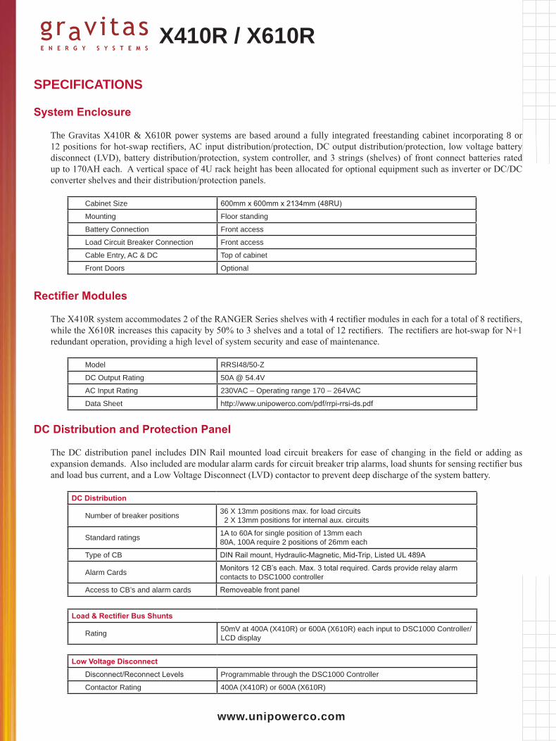
SPECIFICATIONS
System Enclosure
The Gravitas X410R & X610R power systems are based around a fully integrated freestanding cabinet incorporating 8 or 12 positions for hot-swap rectifiers, AC input distribution/protection, DC output distribution/protection, low voltage battery disconnect (LVD), battery distribution/protection, system controller, and 3 strings (shelves) of front connect batteries rated up to 170AH each. A vertical space of 4U rack height has been allocated for optional equipment such as inverter or DC/DC converter shelves and their distribution/protection panels.
Cabinet Size 600mm x 600mm x 2134mm (48RU)
Mounting Floor standing
Battery Connection Front access
Load Circuit Breaker Connection Front access
Cable Entry, AC & DC Top of cabinet
Front Doors Optional
Rectifier Modules
The X410R system accommodates 2 of the RANGER Series shelves with 4 rectifier modules in each for a total of 8 rectifiers, while the X610R increases this capacity by 50% to 3 shelves and a total of 12 rectifiers. The rectifiers are hot-swap for N+1 redundant operation, providing a high level of system security and ease of maintenance.
Model RRSI48/50-Z
DC Output Rating 50A @ 54.4V
AC Input Rating 230VAC – Operating range 170 – 264VAC
Data Sheet http://www.unipowerco.com/pdf/rrpi-rrsi-ds.pdf
DC Distribution and Protection Panel
The DC distribution panel includes DIN Rail mounted load circuit breakers for ease of changing in the field or adding as expansion demands. Also included are modular alarm cards for circuit breaker trip alarms, load shunts for sensing rectifier bus and load bus current, and a Low Voltage Disconnect (LVD) contactor to prevent deep discharge of the system battery.
DC Distribution
Number of breaker positions 36 X 13mm positions max. for load circuits 2 X 13mm positions for internal aux. circuits
Standard ratings 1A to 60A for single position of 13mm each80A, 100A require 2 positions of 26mm each
Type of CB DIN Rail mount, Hydraulic-Magnetic, Mid-Trip, Listed UL 489A
Alarm Cards Monitors 12 CB’s each. Max. 3 total required. Cards provide relay alarm contacts to DSC1000 controller
Access to CB’s and alarm cards Removeable front panel
Load & Rectifier Bus Shunts
Rating 50mV at 400A (X410R) or 600A (X610R) each input to DSC1000 Controller/LCD display
Low Voltage DisconnectDisconnect/Reconnect Levels Programmable through the DSC1000 Controller
Contactor Rating 400A (X410R) or 600A (X610R)
www.unipowerco.com
X410R / X610R
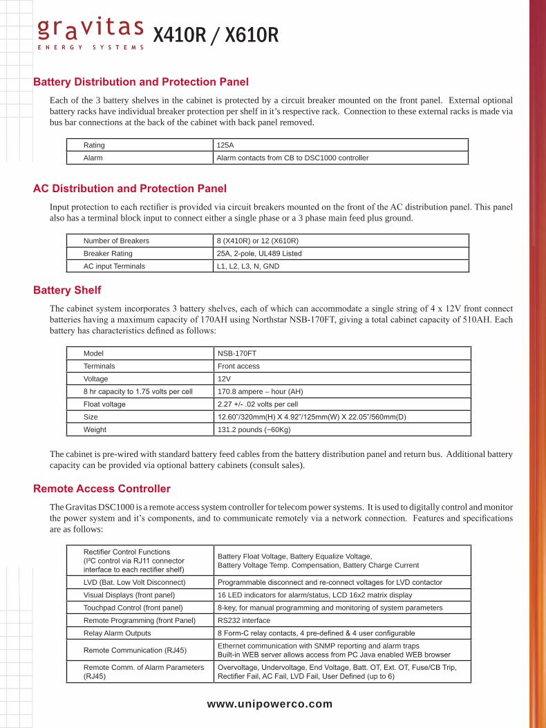
Battery Distribution and Protection PanelEach of the 3 battery shelves in the cabinet is protected by a circuit breaker mounted on the front panel. External optional battery racks have individual breaker protection per shelf in it’s respective rack. Connection to these external racks is made via bus bar connections at the back of the cabinet with back panel removed.
Rating 125A
Alarm Alarm contacts from CB to DSC1000 controller
AC Distribution and Protection PanelInput protection to each rectifier is provided via circuit breakers mounted on the front of the AC distribution panel. This panel also has a terminal block input to connect either a single phase or a 3 phase main feed plus ground.
Number of Breakers 8 (X410R) or 12 (X610R)
Breaker Rating 25A, 2-pole, UL489 Listed
AC input Terminals L1, L2, L3, N, GND
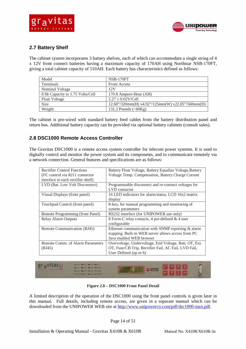
Battery ShelfThe cabinet system incorporates 3 battery shelves, each of which can accommodate a single string of 4 x 12V front connect batteries having a maximum capacity of 170AH using Northstar NSB-170FT, giving a total cabinet capacity of 510AH. Each battery has characteristics defined as follows:
Model NSB-170FT
Terminals Front access
Voltage 12V
8 hr capacity to 1.75 volts per cell 170.8 ampere – hour (AH)
Float voltage 2.27 +/- .02 volts per cell
Size 12.60”/320mm(H) X 4.92”/125mm(W) X 22.05”/560mm(D)
Weight 131.2 pounds (~60Kg)
The cabinet is pre-wired with standard battery feed cables from the battery distribution panel and return bus. Additional battery capacity can be provided via optional battery cabinets (consult sales).
Remote Access ControllerThe Gravitas DSC1000 is a remote access system controller for telecom power systems. It is used to digitally control and monitor the power system and it’s components, and to communicate remotely via a network connection. Features and specifications are as follows:
Rectifier Control Functions (I²C control via RJ11 connector interface to each rectifier shelf)
Battery Float Voltage, Battery Equalize Voltage,Battery Voltage Temp. Compensation, Battery Charge Current
LVD (Bat. Low Volt Disconnect) Programmable disconnect and re-connect voltages for LVD contactor
Visual Displays (front panel) 16 LED indicators for alarm/status, LCD 16x2 matrix display
Touchpad Control (front panel) 8-key, for manual programming and monitoring of system parameters
Remote Communication (RJ45) Ethernet communication with SNMP reporting and alarm trapsBuilt-in WEB server allows access from PC Java enabled WEB browser
Remote Comm. of Alarm Parameters (RJ45)
Overvoltage, Undervoltage, End Voltage, Batt. OT, Ext. OT, Fuse/CB Trip, Rectifier Fail, AC Fail, LVD Fail, User Defined (up to 6)
1. HEALTH AND SAFETY ............................................................................................................................ 7 BATTERY HANDLING PROCEDURE ....................................................................................................... 8 BEFORE REMOVING COVERS OR MAKING ELECTRICAL CONNECTIONS: ...................................... 8 BATTERY DISPOSAL ................................................................................................................................ 8 SAFETY INSTRUCTIONS - BEFORE LIFTING BATTERIES .................................................................... 9 BEFORE INSERTING OR CLOSING BATTERY PROTECTION DEVICES ............................................. 10 CONNECTING RECTIFIERS TO A SYSTEM WITH BATTERIES AND/OR RECTIFIERS ALREADY CONNECTED ............................................................................................................................................ 10
2. INTRODUCTION ..................................................................................................................................... 11 2.1 GENERAL DESCRIPTION ......................................................................................................................... 11 2.2 SYSTEM ENCLOSURE .............................................................................................................................. 12 2.3 RECTIFIER MODULES ............................................................................................................................. 12 2.4 DC DISTRIBUTION AND PROTECTION PANEL ........................................................................................... 13 2.5 BATTERY DISTRIBUTION AND PROTECTION PANEL .................................................................................. 13 2.6 AC DISTRIBUTION AND PROTECTION PANEL ........................................................................................... 13 2.7 BATTERY SHELF .................................................................................................................................... 14 2.8 DSC1000 REMOTE ACCESS CONTROLLER .............................................................................................. 14 2.8 SYSTEM SPECIFICATIONS ....................................................................................................................... 15 2.8 SYSTEM OVERVIEW AND DIMENSIONS .................................................................................................... 15
3. OPERATION ............................................................................................................................................ 16 3.1 SAFETY ................................................................................................................................................. 16 3.2 LED INDICATORS ON THE RECTIFIER FRONT PANEL ................................................................................ 16 3.3 ADDING AND REMOVING RECTIFIERS ...................................................................................................... 16
3.3.1 Removing a Rectifier ...................................................................................................................... 16 3.3.2 Inserting a Rectifier ....................................................................................................................... 17
3.4 DSC1000 SYSTEM CONTROLLER ............................................................................................................ 17 3.4.1 Changing System Operating Parameters ........................................................................................ 17 3.4.2 System Security .............................................................................................................................. 17 3.4.3 Front Panel Description ................................................................................................................. 18 3.4.4 LED Indicators .......................................................................................................................... 19 3.4.5 LCD Alphanumeric Display ....................................................................................................... 20 3.4.6 Keypad ...................................................................................................................................... 20 3.4.7 Description of Operation ............................................................................................................ 21
3.5 ACCESSING SYSTEM STATUS AND PROGRAMMING THROUGH THE FRONT PANEL ............................... 22 3.6 DIRECT OR REMOTE PC CONNECTION.............................................................................................. 29
4. OPERATION ............................................................................................................................................ 30 4.1 ADDING RECTIFIERS .............................................................................................................................. 30 4.2 ADDING BATTERIES ............................................................................................................................... 31 4.3 BATTERY DISCHARGE DATA .................................................................................................................. 32 4.4 ADDING DC LOAD CIRCUIT BREAKERS AND CABLES .............................................................................. 33
5. WIRING AND SCHEMATICS ................................................................................................................ 35 5.1 AC INPUT CONNECTIONS ....................................................................................................................... 35 5.2 DC OUTPUT CONNECTIONS .................................................................................................................... 36 5.3 SYSTEM ALARM AND REMOTE ACCESS CONNECTIONS ............................................................................ 37 5.4 SCHEMATICS ......................................................................................................................................... 38
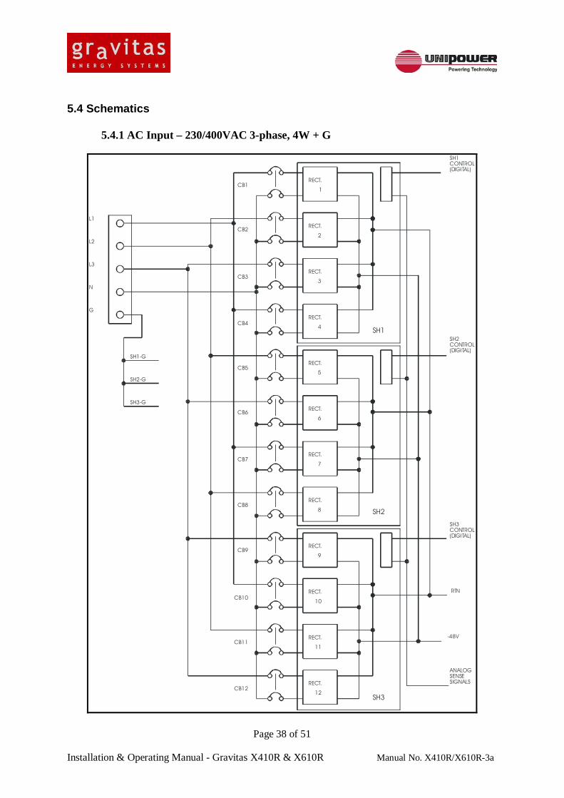
5.4.1 AC Input – 230/400VAC 3-phase, 4W + G ...................................................................................... 38 5.4.2 AC Input – 120/208VAC 3-phase, 3W + G ...................................................................................... 39 5.4.3 DC Output ..................................................................................................................................... 40
WARNING: THIS APPARATUS MUST BE AND MAINTAINED BY TRAINED PERSONNEL. WARNING: THIS APPARATUS MUST BE FIXED TO THE BUILDING IN WHICH IT IS
INSTALLED. WARNING: INDIVIDUAL CABINETS MAY OPERATE FROM A MAINS SUPPLY.
ISOLATE FROM SUPPLY BEFORE REMOVING COVERS FOR MAINTENANCE OR OTHER PURPOSES.
WARNING: THIS APPARATUS HAS A HIGH EARTH LEAKAGE CURRENT. WARNING: WHILE WORKING ON THIS EQUIPMENT, UNSAFE VOLTAGE AND ENERGY
SOURCES MAY BE EXPOSED. ONLY TRAINED, APPROVED MAINTENANCE ENGINEERS SHOULD TEST AND MAINTAIN THIS EQUIPMENT. NO PERSON OTHER THAN THOSE TRAINED TO WORK ON LIVE EQUIPMENT MAY BE PRESENT IN THE WORKING AREA DURING MAINTENANCE UNLESS UNDER DIRECT SUPERVISION OF A COMPETENT PERSON.
WARNING: READ ALL WARNING LABELS. WARNING: READ ANY INSTRUCTIONS SUPPLIED SEPARATELY WITH ANY
COMPONENT PART OF THIS SYSTEM. CAUTION: COMPONENT ASSEMBLIES COMPRISING THIS SYSTEM WHICH INCLUDE
PRINTED CIRCUIT BOARD WIRING ARE LIKELY TO INCLUDE SEMICONDUCTOR DEVICES WHICH ARE SUSCEPTIBLE TO ELECTROSTATIC DISCHARGE. THESE ASSEMBLIES SHOULD ONLY BE HANDLED AFTER TAKING THE NECESSARY PRECAUTIONS ASSOCIATED WITH STATIC DISCHARGE RISK.
BATTERY HANDLING PROCEDURE Batteries present two main hazards: Electrical energy - see below Weight – see "SAFETY INSTRUCTIONS - BEFORE LIFTING BATTERIES" on the following pages.
BEFORE REMOVING COVERS OR MAKING ELECTRICAL CONNECTIONS: 1. Remove watches, jewellery and other metal objects.
"BEFORE CONNECTING RECTIFIER’S TO A SYSTEM WITH BATTERIES AND/OR RECTIFIER’S ALREADY CONNECTED" on the following pages.
4. Use only single-ended, fully insulated tools. Shafts of screwdrivers, etc. should be insulated.
5. Use only isolated instruments and soldering irons.
DANGER OF DEATH OR SERIOUS INJURY EXISTS IF THESE PRECAUTIONS ARE NOT FOLLOWED.
BATTERY DISPOSAL CONTACT THE BATTERY MANUFACTURER FOR INSTRUCTIONS ON THE DISPOSAL OF BATTERIES. THE MANUFACTURER’S ADDRESS IS SHOWN ON THE LABEL ON EACH BATTERY.
SAFETY INSTRUCTIONS - BEFORE LIFTING BATTERIES Manual Handling of Loads Regulations, require that all persons are familiar with the Regulations, that they take care to minimize risk of injury to themselves and others, that they are properly trained, and that the correct equipment is used. 1. Before lifting batteries, stand as close as possible to the battery. 2. Keep the back straight and as vertical as possible. 3. Use the leg muscles to lift in preference to the arms. 4. Minimize twisting, stretching and stooping. 5. Batteries should be withdrawn/inserted evenly, without jerking, maintaining the load level and
balanced, with adequate support. The limits on lifting imposed by the Regulations are:
NOTE: This picture shows the recommended limits for men. For women these weights should be reduced by 30% on average. If twisting of the body is required then all weights should be reduced by 20%.
BEFORE INSERTING OR CLOSING BATTERY PROTECTION DEVICES (Protection devices may include fuses, circuit breakers or links.) 1. Read and follow any safety instructions. 2. Read and follow the user instruction. 3. If a fault occurs do not continue further without diagnosing and clearing it. 4. Check the polarity of the battery connections. 5. Check the sequence of the battery connections. 6. Measure the voltage between the common return and each battery protection device. 7. Check that the battery voltages are in accordance with the manufacturer’s instructions. 8. Ensure that the battery polarities are in accordance with the manufacture’s instructions. 9. Check that any battery voltage differential does not exceed 2V. 10. Ensure that the voltage measured across the first battery protection device is less than 6V. 11. If the voltage measured in 11 above is correct, insert or close the protection device. Repeat steps 11 and 12 for each battery (string) in turn. CONNECTING RECTIFIERS TO A SYSTEM WITH BATTERIES AND/OR RECTIFIERS ALREADY CONNECTED RANGER Series Rectifiers are ‘hot-plug’ devices that may be inserted into or removed from a live system at any time without further intervention. As a precaution against certain types of fault condition, these systems are fitted with AC isolation breakers for each individual Rectifier. It is not normally necessary to switch these off before inserting or removing a Rectifier.
This document is intended to provide information that is required for the safe operation and maintenance of the Gravitas Energy Systems X410R and X610R. Servicing and repairs to these systems must only be performed by qualified engineering personnel – in accordance with the information provided in this manual. UNIPOWER LLC does not accept responsibility for safety, reliability and performance if any modifications or repairs are carried out by unauthorized personnel. UNIPOWER LLC specified replacement parts must be used. Replacement parts, in particular fuses and circuit breakers, must be of the same type and rating to ensure continued protection against risk of fire.
2.1 General Description The X410R & X610R modular DC power systems are designed to meet the stringent requirements of telecom applications where battery backup, reliability, and system flexibility in configuration are key factors. The system is built around a standard 600 x 600 x 2134mm (48U) cabinet enclosure with provision for configuring standard modular assemblies of rectifiers, AC and DC distribution, battery distribution, batteries, and system controller. The cabinet is rated to support loads up to 600A @ -48V, and is configurable to accommodate a variety of AC inputs from either single phase or 3 phase sources. The system is expandable to provide additional battery capacity for extended battery backup time by addition of battery racks. It can also accommodate optional inverter modules, DC/DC modules, and their associated distribution modules for sourcing loads other than the -48V loads.
FEATURES o System installation/operation simplified o Fully integrated cabinet system o Up to 12 hot-swap 50A rectifiers o Up to 600A (32.7kW) load o Up to 36 load circuit breakers (1 to 100A) o AC breakers for individual rectifier inputs o Single or 3 phase inputs o 3 battery shelves, 510AH total o Optional battery cabinets available o 3 battery circuit breakers in cabinet o Low voltage battery disconnect (LVD) o Load and rectifier bus current metering o CB’s field installable o Front access battery terminals o Modular/flexible configuration o Intelligent micro controller o LCD for supervision/setup o Ethernet with SNMP reporting & alarm trapping o Form “C” dry alarm contacts o Options available: o Battery cabinets o Cabinet doors/side panels o Inverter shelves o DC/DC converter shelves
2.2 System Enclosure The Gravitas X410R & X610R power systems are based around a fully integrated freestanding cabinet incorporating 8 or 12 positions for hot-swap rectifiers, AC input distribution/protection, DC output distribution/protection, low voltage battery disconnect (LVD), battery distribution/protection, system controller, and 3 strings (shelves) of front connect batteries rated up to 170AH each. A vertical space of 4U rack height has been allocated for optional equipment such as inverter or DC/DC converter shelves and their distribution/protection panels.
Cabinet Size 600mm x 600mm x 2134mm (48RU) Mounting Floor standing Battery Connection Front access Load Circuit Breaker Connection Front access Cable Entry, AC & DC Top of cabinet Front Doors Optional
2.3 Rectifier Modules The X410R system accommodates 2 of the RANGER Series shelves with 4 rectifier modules in each for a total of 8 rectifiers, while the X610R increases this capacity by 50% to 3 shelves and a total of 12 rectifiers. The rectifiers are hot-swap for N+1 redundant operation, providing a high level of system security and ease of maintenance.
Model RRSI48/50-Z DC Output Rating 50A @ 54.4V AC Input Rating 230VAC – Operating Range 170-264VAC
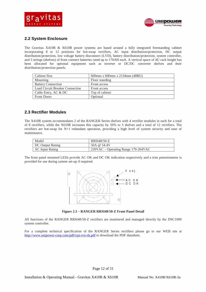
The front panel mounted LEDs provide AC OK and DC OK indication respectively and a trim potentiometer is provided for use during system set-up if required.
Figure 2.3 – RANGER RRSI48/50-Z Front Panel Detail All functions of the RANGER RRSI48/50-Z rectifiers are monitored and managed directly by the DSC1000 system controller. For a complete technical specification of the RANGER Series rectifiers please go to our WEB site at http://www.unipower-corp.com/pdf/rrpi-rrsi-ds.pdf to download the PDF datasheet.
2.4 DC Distribution and Protection Panel The DC distribution panel includes DIN Rail mounted load circuit breakers for ease of changing in the field or adding as expansion demands. Also included are modular alarm cards for circuit breaker trip alarms, load shunts for sensing rectifier bus and load bus current, and a Low Voltage Disconnect (LVD) contactor to prevent deep discharge of the system battery.
DC Distribution Number of breaker positions 36 x 13mm positions max. for load circuits
2 x 13mm positions for internal aux. circuits Standard ratings 1A to 60A for single position of 13mm each
80A & 100A require 2 positions of 26mm each Type of CB DIN rail mount, Hydraulic-Magnetic, Mid-Trip, Listed
alarm contracts to DSC1000 controller Access to CB’s and alarm cards Behind removable front panel
Load & Rectifier Bus Shunts Rating 50mV at 400A (X410R) or 600A (X610R) each input to
DSC1000 Controller/LCD display
Low Voltage Disconnect Disconnect/Reconnect Levels Programmable through the DSC1000 Controller Contactor Rating 400A (X410R) or 600A (X610R)
2.5 Battery Distribution and Protection Panel Each of the 3 battery shelves in the cabinet is protected by a circuit breaker mounted on the front panel. External optional battery racks have individual breaker protection per shelf in it’s respective rack. Connection to these external racks is made via bus bar connections at the back of the cabinet with back panel removed.
Rating 125A Alarm Alarm contacts from CB to DSC1000 controller
2.6 AC Distribution and Protection Panel Input protection to each rectifier is provided via circuit breakers mounted on the front of the AC distribution panel. This panel also has a terminal block input to connect either a single phase or a 3 phase main feed plus ground.
Number of Breakers 8 (X410R) or 12 (X610R) Breaker Rating 25A, 2-pole, UL489 Listed AC Input Terminals L1, L2, L3, N, GND
2.7 Battery Shelf The cabinet system incorporates 3 battery shelves, each of which can accommodate a single string of 4 x 12V front connect batteries having a maximum capacity of 170AH using Northstar NSB-170FT, giving a total cabinet capacity of 510AH. Each battery has characteristics defined as follows:
Model NSB-170FT Terminals Front Access Nominal Voltage 12V 8 Hr Capacity to 1.75 Volts/Cell 170.8 Ampere-Hour (AH) Float Voltage 2.27 ± 0.02V/Cell Size 12.60”/320mm(H) x4.92”/125mm(W) x22.05”/560mm(D) Weight 131.2 Pounds (~60Kg)
The cabinet is pre-wired with standard battery feed cables from the battery distribution panel and return bus. Additional battery capacity can be provided via optional battery cabinets (consult sales).
2.8 DSC1000 Remote Access Controller The Gravitas DSC1000 is a remote access system controller for telecom power systems. It is used to digitally control and monitor the power system and its components, and to communicate remotely via a network connection. General features and specifications are as follows:
Rectifier Control Functions (I²C control via RJ11 connector interface to each rectifier shelf)
Battery Float Voltage, Battery Equalize Voltage,Battery Voltage Temp. Compensation, Battery Charge Current
LVD (Bat. Low Volt Disconnect) Programmable disconnect and re-connect voltages for LVD contactor
Visual Displays (front panel) 16 LED indicators for alarm/status, LCD 16x2 matrix display
Touchpad Control (front panel) 8-key, for manual programming and monitoring of system parameters
configurable Remote Communication (RJ45) Ethernet communication with SNMP reporting & alarm
trapping. Built-in WEB server allows access from PC Java enabled WEB browser
Remote Comm. of Alarm Parameters (RJ45)
Overvoltage, Undervoltage, End Voltage, Batt. OT, Ext. OT, Fuse/CB Trip, Rectifier Fail, AC Fail, LVD Fail, User Defined (up to 6)
Figure 2.8 – DSC1000 Front Panel Detail A limited description of the operation of the DSC1000 using the front panel controls is given later in this manual. Full details, including remote access, are given in a separate manual which can be downloaded from the UNIPOWER WEB site at http://www.unipowerco.com/pdf/dsc1000-man.pdf.
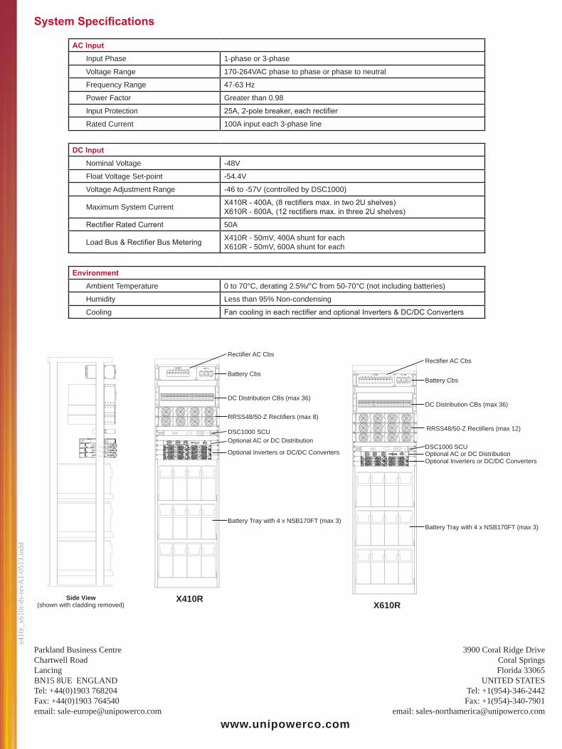
AC Input Input Phase 1-phase or 3-phase Voltage Range 170-264VAC phase-phase or phase-neutral Frequency Range 47-63Hz Power Factor Greater than 0.98 Input Protection 25A, 2-pole circuit breaker per rectifier Rated Current 100A input per phase
DC Output Nominal Voltage -48V Float Voltage Set-Point -54.4V Voltage Adjustment Range -46 to -57V (controller by DSC1000) Maximum System Current X410R – 400A, (8 rectifiers max. in two 2U shelves)
X610R – 600A, (12 rectifiers max. in three 2U shelves) Rectifier Rated Current 50A Load Bus & Rectifier Bus Metering X410R – 50mV, 400A shunt for each
X610R – 50mV, 600A shunt for each
Environmental Ambient Temperature 0 to 70°C, derating 2.5%/°C from 50-70°C
(not including batteries) Humidity Less than 95% Non-condensing Cooling Fan cooling in each rectifier and optional Inverters &
DC/DC Converters
2.8 System Overview and Dimensions
Figure 2.9 – System Overview Detail
Overall cabinet dimensions are 15.2”/600mm(W) x 15.2”/600mm(D) x 84”/2134mm(H) (48U)
3. OPERATION 3.1 Safety IT IS ESSENTIAL THAT USERS OF THIS APPARATUS READ AND FAMILIARISE THEMSELVES WITH THE HEALTH AND SAFETY NOTICES AT THE FRONT OF THIS MANUAL BEFORE CARRYING OUT ANY WORK.
3.2 LED Indicators on the Rectifier Front Panel There are two LEDs on the front panel to indicate the operating status of the rectifier modules. They are as follows:
LED Name LED Colour What it indicates DC OK Green Rectifier functioning normally. AC OK Green AC supply within normal limits.
3.3 Adding and removing rectifiers It should only be necessary to change a rectifier if a rectifier failure alarm has been signaled and it has been determined that failure has indeed occurred. The rectifiers are designed to be “hot-swappable” in that they can be plugged into and out of a “live” shelf. It is not strictly necessary to switch off the AC supply to the rectifier; but if this considered as appropriate then the relevant numbered rectifier AC breaker may be switched off.
3.3.1 Removing a Rectifier To remove a rectifier from the system it is first necessary to release the two locking screws at either side of the front panel of the unit. Withdraw the rectifier carefully from the slot by grasping the handle and pulling towards you. Each rectifier weighs around 10lbs/4.5Kg so it is advisable to support the rear of the unit with the other hand as it is fully extracted from the slot. WARNING!! Take care when removing the rectifier as it may be uncomfortably hot to hold especially if the ambient temperature is high and the unit has been operating at maximum load.
To insert a replacement rectifier hold the unit by the handle supporting the rear with the other hand. Determine correct orientation of the unit by checking that the legend on the front panel is the correct way up and carefully guide the rear of the unit into the slot. Slide the unit firmly all the way into the slot until the front panel is flush with adjacent units. To lock the unit in place, tighten the locking screws at either side of the front panel then switch on the appropriate rectifier AC breaker. Note: If the rectifier AC breaker was not switched off prior to this operation the unit will start automatically approximately 1 second after it has been inserted. During the process of replacing a rectifier the RFA (Rectifier Failure Alarm) LED on the DSC1000 system controller would have been illuminated. Check that this LED has now been extinguished then close and lock the door to the system cabinet.
3.4 DSC1000 System Controller
3.4.1 Changing System Operating Parameters There are three means by which system operating parameters may be altered: 1. Using the front panel controls and display on the DSC1000 system controller. 2. Using a Java enable Internet browser running on a PC that is connected directly to the Ethernet port
on the rear panel of the DSC1000 system controller. 3. Using a Java enabled Internet browser running on a remote PC that is connected via a LAN or
WAN to the DSC1000 system controller.
3.4.2 System Security A security function is employed in the DSC1000 system controller such that it is impossible to change any of the system operating parameters without the use of a passcodes. Two passcodes are employed in the DSC1000 with factory defaults of ‘111’ for the level 1 passcode and ‘123’ for the level 2 passcode. These may be changed from the front panel as well as remotely.
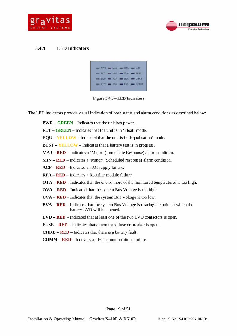
On the left side of the front panel are 16 LED indicators which display various status and alarm conditions. These are described in more detail in section 10.
At the centre of the panel is a 16 Character, 2 Line Alphanumeric LCD Display. This display provides information about a range of different system parameters and may also be used in conjunction with the keypad to the right to setup all system parameters other than the alarm matrix (discussed later) and the SNMP facility.
On the right side is the 8-Key control panel that is used in conjunction with the LCD Display to the left in order to set and display all systems parameters with the exception of the alarm matrix and the SNMP facility.
Notes: The primary means of setting up the DSC1000 unit is via it’s built-in WEB server, which is accessed using a WEB browser via the Ethernet TCP/IP connection.
The RS232 Connector mounted at the right side of the front panel is provided for UNIPOWER LLC use only as a CONSOLE port.
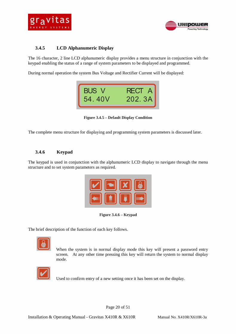
3.4.5 LCD Alphanumeric Display The 16 character, 2 line LCD alphanumeric display provides a menu structure in conjunction with the keypad enabling the status of a range of system parameters to be displayed and programmed.
During normal operation the system Bus Voltage and Rectifier Current will be displayed:
BUS V RECT A54. 40V 202. 3A
Figure 3.4.5 – Default Display Condition
The complete menu structure for displaying and programming system parameters is discussed later.
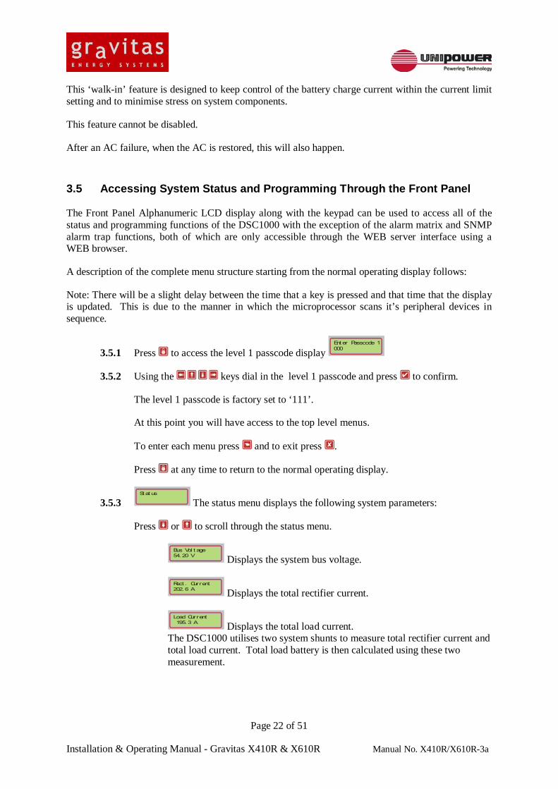
3.4.6 Keypad The keypad is used in conjunction with the alphanumeric LCD display to navigate through the menu structure and to set system parameters as required.
Figure 3.4.6 – Keypad
The brief description of the function of each key follows.
When the system is in normal display mode this key will present a password entry screen. At any other time pressing this key will return the system to normal display mode.
Used to confirm entry of a new setting once it has been set on the display.
Used to cancel the last entry. Pressing this key several times will return the display to the top STATUS menu.
Used to enter the displayed menu or parameter setup.
Used to navigate up and down through the menus and to scroll through the alphabet or numbers when programming a parameter.
Used to select the next or previous character or digit when programming a parameter.
3.4.7 Description of Operation
The DSC1000 controls and monitors the 2 (X410R) or 3 (X610R) rectifier shelves containing up to four rectifiers each. The DSC1000 controls the rectifier output voltage which is preset by float voltage and equalize voltage settings programmed into the unit. Further fine voltage control is provided through a set of temperature compensation settings appropriate to the batteries being employed with the system.
Through the I²C interface that is employed to communicate with the rectifiers the DSC1000 also monitors a number of other rectifier parameters including AC OK, DC OK, Temperature Alarm, Fan OK and Internal Temperature.
Inventory information stored on an EPROM in the rectifier module including Model No., Serial No., Part No., Revision No., Country of Manufacture and Name of Manufacturer is also available and displayed of the ‘Rectifier Status’ WEB page when the unit is interrogated using a WEB browser.
The DSC1000 also monitors a number of other system parameters including Bus Voltage, Rectifier Current, Load Current, Battery Temperature, Cabinet Temperature, its own Internal Temperature, LVD Status and Fuse/Breaker Status.
The unit also has up to 6 further undedicated contact closure inputs which may be used to monitor various other external conditions.
The DSC1000 provides up to 8 Form-C relay alarm outputs. Two of these are dedicated to ‘Major’ (Immediate Response) and ‘Minor’ (Scheduled Response) alarms while the other 6 may be programmed to provide alarms for various fault conditions.
IMPORTANT NOTE: When a power system controlled by the DSC1000 is first powered up, you will notice that the bus voltage is not at the level as set by the float voltage setting. This is completely normal. The bus voltage will slowly be increased over around 15 minutes until the final float voltage is reached.
This ‘walk-in’ feature is designed to keep control of the battery charge current within the current limit setting and to minimise stress on system components.
This feature cannot be disabled.
After an AC failure, when the AC is restored, this will also happen.
3.5 Accessing System Status and Programming Through the Front Panel The Front Panel Alphanumeric LCD display along with the keypad can be used to access all of the status and programming functions of the DSC1000 with the exception of the alarm matrix and SNMP alarm trap functions, both of which are only accessible through the WEB server interface using a WEB browser.
A description of the complete menu structure starting from the normal operating display follows:
Note: There will be a slight delay between the time that a key is pressed and that time that the display is updated. This is due to the manner in which the microprocessor scans it’s peripheral devices in sequence.
3.5.1 Press to access the level 1 passcode display Ent er Passcode 1000
3.5.2 Using the keys dial in the level 1 passcode and press to confirm.
The level 1 passcode is factory set to ‘111’.
At this point you will have access to the top level menus.
To enter each menu press and to exit press .
Press at any time to return to the normal operating display.
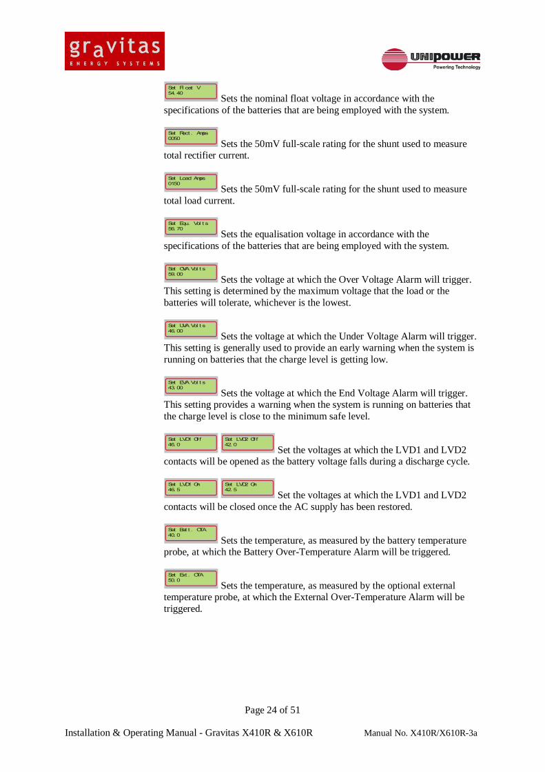
3.5.3 St at us
The status menu displays the following system parameters:
Press or to scroll through the status menu.
Bus Vol t age54. 20 V Displays the system bus voltage.
Rect . Current202. 6 A Displays the total rectifier current.
Load Current 195. 3 A Displays the total load current.
The DSC1000 utilises two system shunts to measure total rectifier current and total load current. Total load battery is then calculated using these two measurement.
Bat t ery Current 7. 3 A Displays the battery current.
A positive value indicates a charging current while a negative value indicates a discharge current, when the system is running on batteries.
Bat t ery Temp.+25. 0 C°
Displays the battery temperature. Battery temperature is measured using a probe supplied with the DSC1000 that is attached to one of the battery terminals.
Cont rol l er Temp.+37. 5 C°
Displays the DSC1000 control unit’s internal temperature.
Ext ernal Temp.+21. 3 C°
Displays the temperature measured by an optional measurement probe. This probe would generally be installed in a location appropriate to obtain a measure of ambient temperature in the equipment room in which a power system is installed.
AC1 Vol t age209 V
AC2 Vol t age209 V
AC3 Vol t age209 V
Display the individual phase voltages of a 3-phase AC supply feed to the power system using an optional 3-phase measurement module. For a single phase application only the AC1 is used.
Ti me 24H20: 43: 28
Dat e MM/ DD/ YYYY01/ 01/ 2005
Displays the system date and time. The DSC1000 contains a real-time clock with its own internal battery supply. This clock can be synchronised with the real-time clock of any system connected through the WEB interface.
Number of rect s. 12
Displays the number of rectifiers installed in the power system.
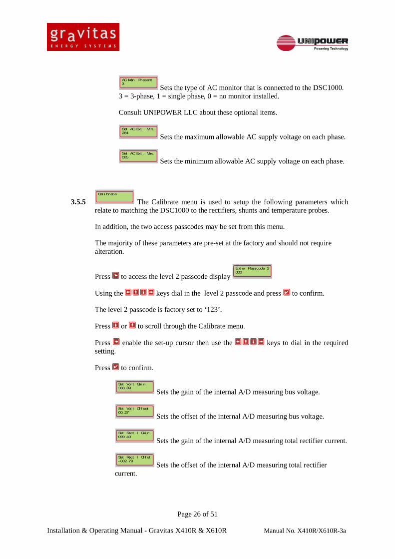
3.5.4 I nst al l
The Install menu is used to set up the following parameters at the time of system installation:
Press or to scroll through the Install menu.
Press enable the set-up cursor then use the keys to dial in the required setting.
Press to confirm.
Si t e Namecoral spr i ngs f l
Optional setting which may be used to identify the location of the unit.
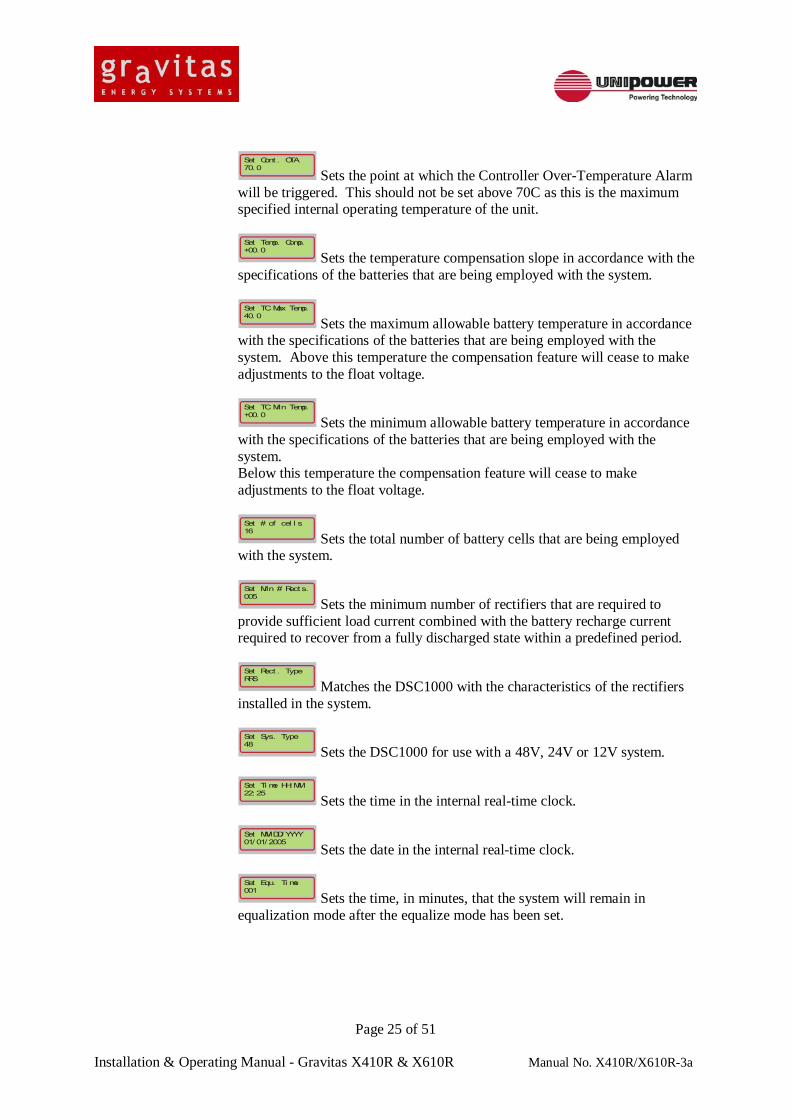
Sets the nominal float voltage in accordance with the specifications of the batteries that are being employed with the system.
Set Rect . Amps0050
Sets the 50mV full-scale rating for the shunt used to measure total rectifier current.
Set Load Amps0150
Sets the 50mV full-scale rating for the shunt used to measure total load current.
Set Equ. Vol t s56. 70
Sets the equalisation voltage in accordance with the specifications of the batteries that are being employed with the system.
Set OVA Vol t s59. 00
Sets the voltage at which the Over Voltage Alarm will trigger. This setting is determined by the maximum voltage that the load or the batteries will tolerate, whichever is the lowest.
Set UVA Vol t s46. 00
Sets the voltage at which the Under Voltage Alarm will trigger. This setting is generally used to provide an early warning when the system is running on batteries that the charge level is getting low.
Set EVA Vol t s43. 00
Sets the voltage at which the End Voltage Alarm will trigger. This setting provides a warning when the system is running on batteries that the charge level is close to the minimum safe level.
Set LVD1 Of f46. 0
Set LVD2 Of f42. 0
Set the voltages at which the LVD1 and LVD2 contacts will be opened as the battery voltage falls during a discharge cycle.
Set LVD1 On46. 5
Set LVD2 On42. 5
Set the voltages at which the LVD1 and LVD2 contacts will be closed once the AC supply has been restored.
Set Bat t . OTA40. 0
Sets the temperature, as measured by the battery temperature probe, at which the Battery Over-Temperature Alarm will be triggered.
Set Ext . OTA50. 0
Sets the temperature, as measured by the optional external temperature probe, at which the External Over-Temperature Alarm will be triggered.
Sets the point at which the Controller Over-Temperature Alarm will be triggered. This should not be set above 70C as this is the maximum specified internal operating temperature of the unit.
Set Temp. Comp.+00. 0
Sets the temperature compensation slope in accordance with the specifications of the batteries that are being employed with the system.
Set TC Max Temp.40. 0
Sets the maximum allowable battery temperature in accordance with the specifications of the batteries that are being employed with the system. Above this temperature the compensation feature will cease to make adjustments to the float voltage.
Set TC Mi n Temp.+00. 0
Sets the minimum allowable battery temperature in accordance with the specifications of the batteries that are being employed with the system. Below this temperature the compensation feature will cease to make adjustments to the float voltage.
Set # of cel l s16
Sets the total number of battery cells that are being employed with the system.
Set Mi n # Rect s.005
Sets the minimum number of rectifiers that are required to provide sufficient load current combined with the battery recharge current required to recover from a fully discharged state within a predefined period.
Set Rect . TypeRRS
Matches the DSC1000 with the characteristics of the rectifiers installed in the system.
Set Sys. Type48
Sets the DSC1000 for use with a 48V, 24V or 12V system.
Set Ti me HH: MM22: 25
Sets the time in the internal real-time clock.
Set MM/ DD/ YYYY01/ 01/ 2005
Sets the date in the internal real-time clock.
Set Equ. Ti me001
Sets the time, in minutes, that the system will remain in equalization mode after the equalize mode has been set.
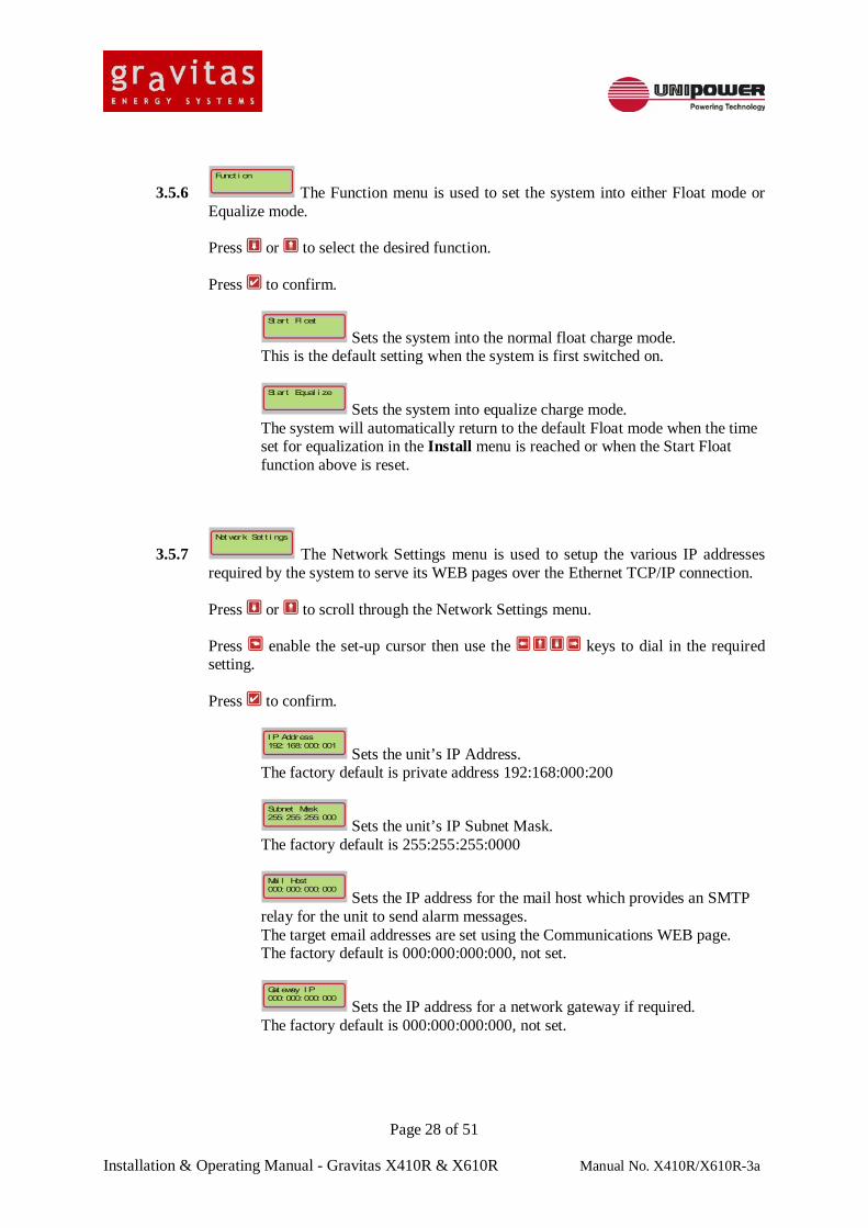
The Function menu is used to set the system into either Float mode or Equalize mode.
Press or to select the desired function.
Press to confirm.
St art Fl oat
Sets the system into the normal float charge mode. This is the default setting when the system is first switched on.
St art Equal i ze
Sets the system into equalize charge mode. The system will automatically return to the default Float mode when the time set for equalization in the Install menu is reached or when the Start Float function above is reset.
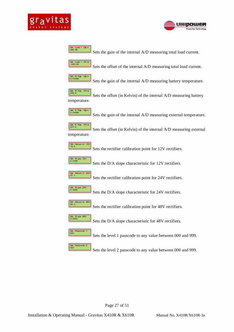
3.5.7 Net work Set t i ngs
The Network Settings menu is used to setup the various IP addresses required by the system to serve its WEB pages over the Ethernet TCP/IP connection.
Press or to scroll through the Network Settings menu.
Press enable the set-up cursor then use the keys to dial in the required setting.
Press to confirm.
I P Address192: 168: 000: 001
Sets the unit’s IP Address. The factory default is private address 192:168:000:200
Subnet Mask255: 255: 255: 000
Sets the unit’s IP Subnet Mask. The factory default is 255:255:255:0000
Mai l Host000: 000: 000: 000
Sets the IP address for the mail host which provides an SMTP relay for the unit to send alarm messages. The target email addresses are set using the Communications WEB page. The factory default is 000:000:000:000, not set.
Gat eway I P000: 000: 000: 000
Sets the IP address for a network gateway if required. The factory default is 000:000:000:000, not set.
Sets the service that will be used to transfer emails when required. The factory default is ‘unset’. If the email service is to be used then this must be set to ‘Eth’.
Mac Address88: 88: 88: 88: 88: 8
Displays the unique Mac Address identity of the Ethernet control IC installed in the DSC1000.
3.6 Direct or Remote PC Connection Details for using the DSC1000 remote WEB page functions are given in the separate DSC1000 manual that can be downloaded from the UNIPOWER WEB site at http://www.unipowerco.com/pdf/dsc1000-man.pdf.
This manual also provides detailed information about the SNMP reporting & alarm trap feature and its related MIB files.
4. OPERATION System upgrades that can be carried out are listed below:
- Addition of rectifiers, up to a maximum of 8 for the X410R or 12 for the X610R.
- Addition of battery strings.
- Addition of DC Load circuit breakers.
All upgrades can be carried out without the need to power down the system, although it should be noted that during an upgrade some alarm conditions may occur and that these should be ignored.
WARNING: TO ENSURE OVERALL SYSTEM INTEGRITY UPGRADES SHOULD ONLY BE CARRIED OUT BY APPROPRIATELY TRAINED INSTALLATION AND MAINTENANCE PERSONNEL.
4.1 Adding Rectifiers The system cabinet provides a total of 12 rectifier slots. Rectifier slots are numbered 1 to 12 starting at the top left-hand position and working across and down to the bottom right-hand position. Before installing (a) new rectifier(s) it is necessary to remove the blanking panel(s) from the next numbered slot(s) into which the rectifier(s) will be installed. An appropriate Philips screwdriver is required to release the two retaining screws that hold the blanking plate in place. To insert a replacement rectifier hold the unit by the handle supporting the rear with the other hand. Determine correct orientation of the unit by checking that the legend on the front panel is the correct way up and carefully guide the rear of the unit into the slot. Slide the unit firmly all the way into the slot until the front panel is flush with adjacent units. To lock the unit in place, tighten the locking screws at either side of the front panel. To switch the rectifier on, close the appropriately numbered “Rectifier AC” circuit breaker located at the top of the cabinet. Note: When rectifiers are added to a system, either to increase system capacity or reduce to battery recharge time by providing extra recharge current, it is necessary to change the setting for the minimum number of rectifiers required in the system. This setting change can be made either through the front panel controls as described in section 3.5.4 of this manual or section 16.4 of the separate DSC1000 manual. This setting may also be changed through the remote WEB interface as described in section 17.4 of the DSC1000 manual under ‘Controller Site Installation’.
4.2 Adding Batteries WARNING: ALL BATTERY CONNECTIONS PRESENT A HAZARD DUE TO THE DANGER
OF SHORT CIRCUITS. ALL JEWELLERY, RINGS AND WATCHES MUST BE REMOVED AND ONLY SINGLE-ENDED INSULATED TOOLS SHOULD BE USED WHEN WORKING ON BATTERIES.
ENSURE THAT THE BATTERY CIRCUIT BREAKERS HAVE BEEN SWITCHED OFF AND
THE BATTERY CABLES DISCONNECTED AT THE BATTERY END BEFORE PROCEEDING FURTHER.
FAILURE TO DO SO MAY RESULT IN SERIOUS INJURY OR DAMAGE TO THE SYSTEM. Batteries are supplied separate from the rest of the equipment. Before proceeding with installation the original manufacturer’s instructions for installation must be read. CAUTION: BATTERIES CAN BE VERY HEAVY. SEE “SAFETY INSTRUCTIONS – BEFORE LIFTING BATTERIES” IN SECTION
1 OF THIS MANUAL. Once the batteries have been installed onto the shelves connections can be made as follows: Proceed with one string at a time.
1. Ensure that the circuit breakers associated with the shelves on which the batteries are to be installed are switched off.
2. Install the 4 batteries on the lowest shelf first taking note of the safety instructions “before
lifting batteries” in section 1 of this manual. 3. Install the interconnect strips between the individual cells. 4. Connect the +Ve Common cable to the +Ve terminal of the end cell. 5. Connect the –Ve cable to the –Ve terminal of the other end cell. 6. Check that the polarity and voltage of each battery string is correct for this system. The
voltage level should be around 50V in each case. 7. Proceed as in 2 to 6 above until all new battery strings have been installed. 8. Switch on the associated battery circuit breakers in turn.
4.3 Battery Discharge Data The following table provides a basic guide to determining the current number of battery strings to achieve the desired discharge time for a given load current. The X410R/X610R system cabinet has room to accommodate up to 3 strings of batteries. For applications requiring more than this please consult sales for information about additional battery cabinets or battery shelves. Discharge Current (Amps) for 48V Systems
Recommended maximum load current per battery string = 100A
Note that a 125A breaker is employed for each battery string in the system cabinet.
Amperes in table are load current capacities available based on required discharge time in hours and number of battery strings using NorthStar NSB-170-FT batteries.
The data is based on constant current discharge at an ambient temperature of 25DegC with end of discharge (EOD) equal to 1.75 V/Cell. For other values of ambient temperature and EOD review the battery manufacturer’s specifications.
4.4 Adding DC Load Circuit Breakers and Cables This system has been constructed with all necessary bus-bars and mounting brackets in place to allow the incorporation of up to 36 circuit breakers of up to 100A capacity to provide a distributed output to various separate Telecoms equipments. It is important when adding load equipment that the correct rating of breaker is used for each circuit and that the total current consumption of all circuits added does not exceed that which is available having taken into account the actual current being taken already by other equipment and that required to recharge the batteries from a fully discharged state within the required time following a power outage. It is recommended that if breakers and cables are to be installed by other than UNIPOWER LLC personnel consultation with Unipower should be undertaken to ensure that the above referred to criteria will continue to be met. CAUTION: WHEN WORKING ON THIS EQUIPMENT UNSAFE VOLTAGE SOURCES AND
ENERGY HAZARDS MAY BE EXPOSED. ONLY TRAINED AND APPROVED PERSONNEL SHOULD INSTALL, TEST AND MAINTAIN THIS EQUIPMENT. NO PERSON OTHER THAN THOSE TRAINED TO WORK ON LIVE EQUIPMENT MAY BE PRESENT IN THE WORKING AREA DURING INSTALLATION, TESTING OR MAINTENANCE UNLESS DIRECTLY UNDER THE SUPERVISION OF A COMPETENT PERSON.
When installing a new circuit breaker follow the procedure below: Using an appropriate screwdriver remove the front access panel in the system cabinet and, if necessary the appropriate blanking panel. Place the circuit breaker over the DIN mounting rail and at the same time ensure that the appropriate ‘tooth’ on the copper bus-bar is correctly inserted into the terminal socket. To fix the circuit breaker in place tighten the screw in the terminal socket. To install the circuit cables follow the procedure below: 1. Make sure that the circuit breaker which is to be connected to is switched off. 2. Feed the cables from the equipment to be connected to the auxiliary circuit in though the bottom of
the cabinet. Note: Always start at the equipment end. 3. Connect the positive ground cable to the positive bus-bar having terminated it with an appropriate
ring crimp terminal. Ensure that the bolt is adequately tightened. 4. Remove the equivalent alarm cable from terminal 1A thru 12A on the alarm card immediately
below and feed this up behind the breaker ready for insertion into the open terminal socket along with the negative 48V cable for the load as described next.
5. Connect the negative 48V cable for the load along with the associated alarm cable into the open
terminal socket of the circuit breaker making sure that the terminal screw is adequately tightened.
6. Ensure that the far end of the load circuit cable is correctly connected to the equipment that is to be
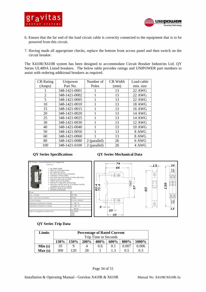
powered from this circuit. 7. Having made all appropriate checks, replace the bottom front access panel and then switch on the
circuit breaker. The X410R/X610R system has been designed to accommodate Circuit Breaker Industries Ltd. QY Series UL489A Listed breakers. The below table provides ratings and UNIPOWER part numbers to assist with ordering additional breakers as required.
5. Wiring and Schematics This section provides details of connections to the system and schematics of the system as a whole.
5.1 AC Input Connections The X410R and X610R systems will operate from any of the following AC sources:
• 1-phase where the phase to neutral voltage is in the range 170-264VAC. • 3-phase star connected where the phase to neutral voltage is in the range 170-264VAC. • 3-phase delta or star connected where the phase to phase voltage is in the range 170-264VAC.
The supply frequency must be in the range 47-63Hz for correct operation of the rectifiers. The rated input current is 100A per phase line and Neutral. The required cable sizes are as follows: 120/208VAC systems – 2AWG 230/400VAC systems – 6AWG
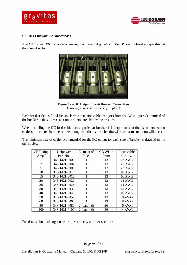
5.2 DC Output Connections The X410R and X610R systems are supplied pre-configured with the DC output breakers specified at the time of order.
Figure 5.2 – DC Output Circuit Breaker Connections (showing alarm cables already in place)
Each breaker that is fitted has an alarm connection cable that goes from the DC output side terminal of the breaker to the alarm detection card mounted below the breaker. When installing the DC load cable into a particular breaker it is important that the alarm connection cable is re-inserted into the breaker along with the load cable otherwise an alarm condition will occur. The minimum size of cable recommended for the DC output for each size of breaker is detailed in the table below:
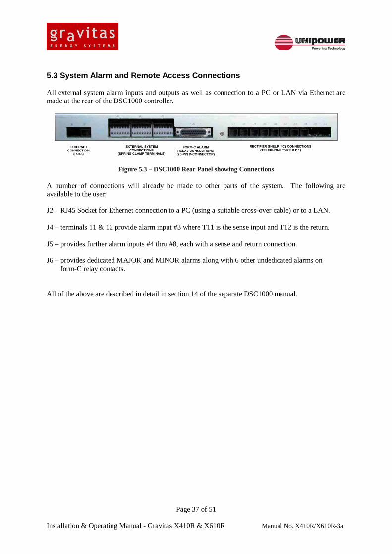
5.3 System Alarm and Remote Access Connections All external system alarm inputs and outputs as well as connection to a PC or LAN via Ethernet are made at the rear of the DSC1000 controller.
A number of connections will already be made to other parts of the system. The following are available to the user: J2 – RJ45 Socket for Ethernet connection to a PC (using a suitable cross-over cable) or to a LAN. J4 – terminals 11 & 12 provide alarm input #3 where T11 is the sense input and T12 is the return. J5 – provides further alarm inputs #4 thru #8, each with a sense and return connection. J6 – provides dedicated MAJOR and MINOR alarms along with 6 other undedicated alarms on form-C relay contacts. All of the above are described in detail in section 14 of the separate DSC1000 manual.
6. Maintenance 6.1 Safety Precautions BEFORE REMOVING COVERS OR MAKING ELECTRICAL CONNECTIONS:
REMOVE WATCHES, JEWELLERY AND OTHER METAL OBJECTS REMOVE OR COVER ALL RINGS READ AND FOLLOW - "SAFETY INSTRUCTIONS - BEFORE LIFTING BATTERIES" , "BEFORE INSERTING/CLOSING BATTERY PROTECTION DEVICES", AND "BEFORE CONNECTING RECTIFIERS TO A SYSTEM WITH BATTERIES AND/OR RECTIFIERS ALREADY CONNECTED" IN SECTION 1 HEALTH AND SAFETY. USE ONLY SINGLE-ENDED, FULLY INSULATED TOOLS. SHAFTS OF SCREWDRIVERS, ETC., SHOULD 8E INSULATED. USE ONLY ISOLATED INSTRUMENTS AND SOLDERING IRONS
DANGER OF DEATH OR SERIOUS INJURY EXISTS IF THESE PRECAUTIONS ARE NOT FOLLOWED. REFER TO SECTION 1 HEALTH AND SAFETY BEFORE PROCEEDING.
6.2 Safe Working Procedure Hazardous voltage levels exist in the primary circuits of, and supplies to, Rectifiers. Although secondary circuits are usually at levels below the statutory hazardous limit, this may not always be so and should not be relied upon. All voltages should be treated as potentially hazardous. Remember that voltage sources from other equipment may be present in the equipment being worked on, via parallel systems, alarms, etc. An energy hazard exists in batteries and capacitors, even when not charged to hazardous voltages. If the equipment is to be isolated, the following areas must be considered: 1. AC and DC inputs from all sources. 2. Output from parallel systems. 3. Power factor correction and filter capacitors. 4. Battery: Use of the isolator MCB may not be sufficient, as it may be necessary to work close to the
isolator's connections. In this case, also remove at least one cable from the battery and isolate the exposed connections.
Note that "Isolation" in terms of the Electricity at Work Regulations means the methods by which it is assured that hazards such as batteries and power cannot be re-connected inadvertently by those working on the equipment, or by others. Such methods include having a switch in view at all times, and the use of lockouts.
ALWAYS REMOVE EARTHED-END CONNECTIONS FIRST, AND RE-CONNECT THEM LAST. When re-connecting sources of power and/or stored energy, such as rectifiers, batteries and large capacitors, switch on the rectifiers first and check that the voltage difference between the items to be inter-connected is small before making the connection. Refer to the Health and Safety section at the beginning of this manual. 6.3 Handling All stages which involve handling of assemblies fitted with any semiconductor components should contain protection against the possibility of static induced damage. The printed circuit cards should only be removed from their protective carriers in static-safe handling areas by persons wearing static protection such as wrist straps. ANY SUCTION CLEANER OR BLOWER USED MUST HAVE A NONMETALLIC HOSE AND TOOLS TO AVOID DANGER OF SHORT CIRCUITING.
6.4 Cleaning A step-ladder is required for access to the top of the cabinets. Unlock and open the cabinet doors. Use a suction cleaner and a fully insulated soft brush to remove any accumulated dust. Pay particular attention to the following areas:
• Inside the doors and around the foot of the cabinet. • Around any fan guards. • Around any openings to the cabinet.
6.5 Inspection Annual inspection should include a check of the battery terminals for any sign of corrosion and the terminals should be greased as necessary. A check of the battery terminal connection torque should also be made with reference to the torque setting advised by the battery manufacturer. The expected life of a battery is ten years. It is recommended that a complete battery set should be replaced after ten years in service. All load connections should also be inspected to ensure that they are sufficiently tight.
6.6 Rectifier Maintenance Other than general cleaning away of accumulated dust the rectifiers are non-serviceable items. In the unlikely event that a rectifier has failed it must be returned to UNIPOWER LLC for repair or replacement. 6.7 Integrity of Electrical Connections It is good practice to check all accessible electrical connections at regular intervals to ensure that no "hot spots" develop over time due to loose connections. The use of single ended insulated tools is essential for this process.
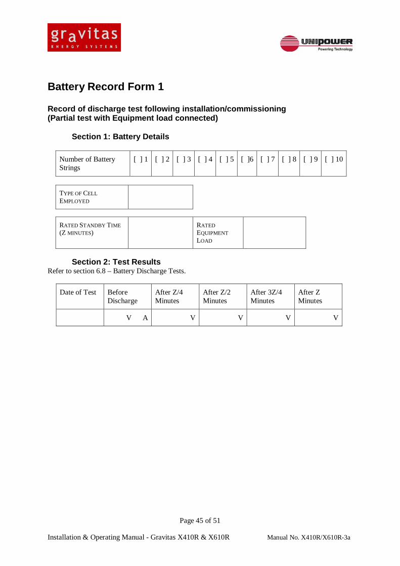
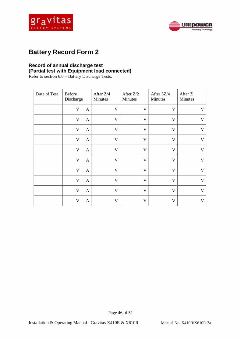
6.8 Battery Tests Battery Tests should be carried out annually in accordance with the manufacturer’s recommendations, or alternatively as follows. A battery discharge test should normally be carried out during the commissioning procedure. This will provide (a) a guide to standby capacity and (b) as a basis for comparison with future tests during the battery lifetime. The battery should be allowed to float charge for at least 6 days. Then follow the test procedure as below: 1. Determine the system rated standby time Z minutes. This should be the same figure as was
recorded on BATTERY RECORD FORM 1 when the system was commissioned.
2. Note the system output voltage from the DSC1000 display, and record the reading on BATTERY RECORD FORM 2.
3. Turn off the AC supply to the System cabinet, or trim down the rectifiers using the DSC1000 controller.
4. Immediately measure the Power System output load current. Note the reading on BATTERY RECORD FORM 2.
5. Leaving the load equipment connected, it will draw its power from the battery during the test, partially discharging the battery. The equipment should continue to function normally.
6. After a discharge time of Z/4 minutes (25% of system rated standby time) has elapsed, note the system output voltage as indicated on PSC-1000 on BATTERY RECORD FORM 2.
7. After a discharge time of Z/2 minutes (50% of system rated standby time) has elapsed, note the system output voltage on the BATTERY RECORD FORM 2.
8. After a discharge time of 3Z/4 minutes (75% of system rated standby time) has elapsed, note the system output voltage on the BATTERY RECORD FORM 2.
9. After a discharge time of Z minutes (100% of system rated standby time) has elapsed, note the system output voltage on the BATTERY RECORD FORM 2.
10. End the battery test by switching on the AC supply, or trimming up the rectifiers using the DSC1000 controller, when the output voltage has reduced to 45 volts.
Battery Record Form 1 Record of discharge test following installation/commissioning (Partial test with Equipment load connected) Section 1: Battery Details
7. Fault Finding and Replacement Procedures 7.1 Safety Precautions BEFORE REMOVING COVERS OR MAKING ELECTRICAL CONNECTIONS:
REMOVE WATCHES, JEWELLERY AND OTHER METAL OBJECTS REMOVE OR COVER ALL RINGS READ AND FOLLOW - "SAFETY INSTRUCTIONS - BEFORE LIFTING BATTERIES" , "BEFORE INSERTING/CLOSING BATTERY PROTECTION DEVICES", AND "BEFORE CONNECTING RECTIFIERS TO A SYSTEM WITH BATTERIES AND/OR RECTIFIERS ALREADY CONNECTED" IN SECTION 1 HEALTH AND SAFETY. USE ONLY SINGLE-ENDED, FULLY INSULATED TOOLS. SHAFTS OF SCREWDRIVERS, ETC., SHOULD 8E INSULATED. USE ONLY ISOLATED INSTRUMENTS AND SOLDERING IRONS
DANGER OF DEATH OR SERIOUS INJURY EXISTS IF THESE PRECAUTIONS ARE NOT FOLLOWED. REFER TO SECTION 1 HEALTH AND SAFETY BEFORE PROCEEDING.
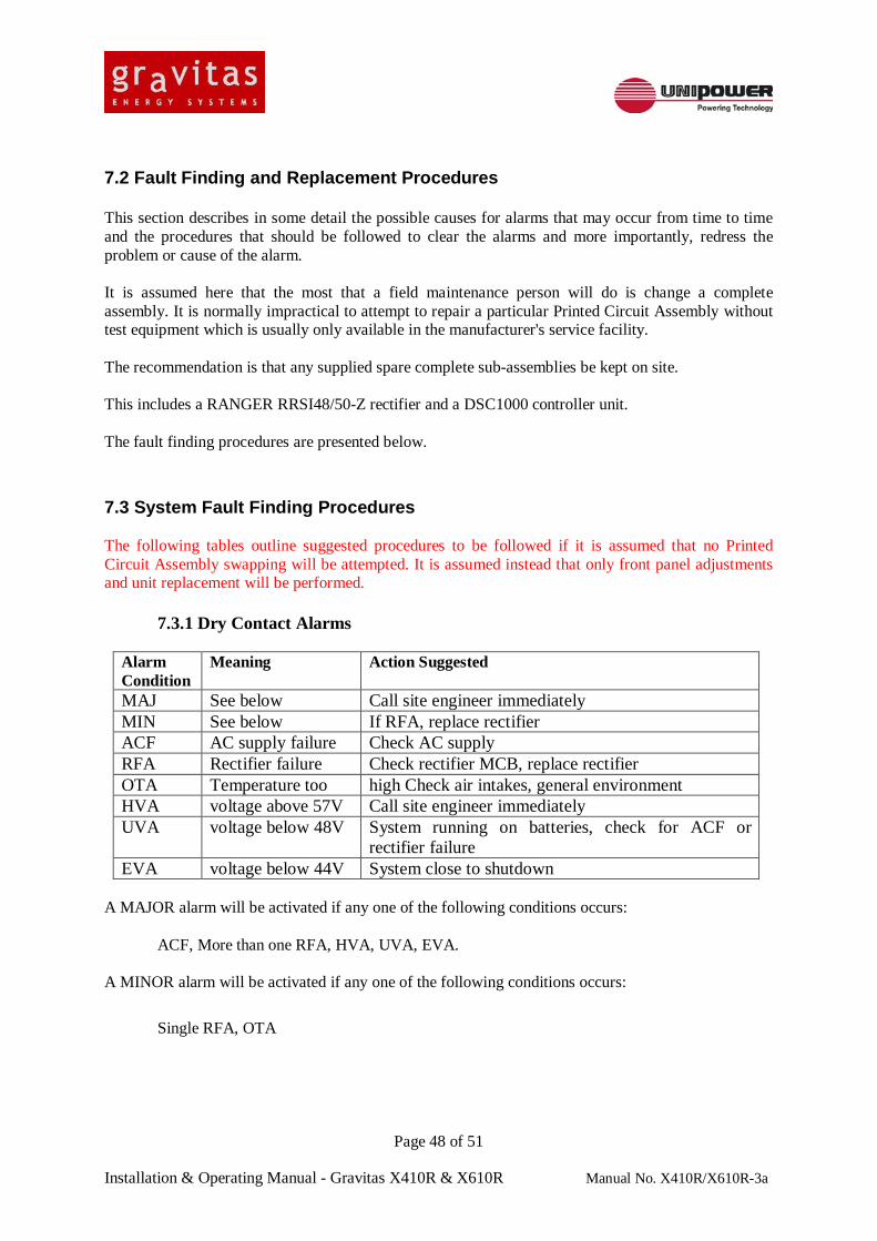
7.2 Fault Finding and Replacement Procedures This section describes in some detail the possible causes for alarms that may occur from time to time and the procedures that should be followed to clear the alarms and more importantly, redress the problem or cause of the alarm. It is assumed here that the most that a field maintenance person will do is change a complete assembly. It is normally impractical to attempt to repair a particular Printed Circuit Assembly without test equipment which is usually only available in the manufacturer's service facility. The recommendation is that any supplied spare complete sub-assemblies be kept on site. This includes a RANGER RRSI48/50-Z rectifier and a DSC1000 controller unit. The fault finding procedures are presented below.
7.3 System Fault Finding Procedures The following tables outline suggested procedures to be followed if it is assumed that no Printed Circuit Assembly swapping will be attempted. It is assumed instead that only front panel adjustments and unit replacement will be performed.
7.3.1 Dry Contact Alarms
Alarm Condition
Meaning Action Suggested
MAJ See below Call site engineer immediately MIN See below If RFA, replace rectifier ACF AC supply failure Check AC supply RFA Rectifier failure Check rectifier MCB, replace rectifier OTA Temperature too high Check air intakes, general environment HVA voltage above 57V Call site engineer immediately UVA voltage below 48V System running on batteries, check for ACF or
rectifier failure EVA voltage below 44V System close to shutdown
A MAJOR alarm will be activated if any one of the following conditions occurs: ACF, More than one RFA, HVA, UVA, EVA. A MINOR alarm will be activated if any one of the following conditions occurs:
MAJ Indicates a ‘Major’ (Immediate Response) alarm condition.
MIN Indicates a ‘Minor’ (Scheduled response) alarm condition.
ACF Indicates an AC supply failure.
RFA Indicates a Rectifier module failure.
OTA Indicates that the one or more of the monitored temperatures is too high.
OVA Indicated that the system Bus Voltage is too high.
UVA Indicates that the system Bus Voltage is too low.
EVA Indicates that the system Bus Voltage is nearing the point at which the battery LVD will be opened.
LVD Indicated that at least one of the two LVD contactors is open.
FUSE Indicates that a monitored fuse or breaker is open.
CHKB Indicates that there is a battery fault.
COMM Indicates an I²C communications failure.
7.4 DSC1000 Fault Finding and Repair Procedures In addition to performing a supervisory function, by monitoring output voltage and current and the various other system parameters, the DSC1000 also performs a voltage control function in order to achieve battery charging current control, battery temperature compensation and battery equalization. If at any time the DSC1000 is diagnosed as being faulty a system maintenance shutdown should be scheduled. In the event that replacement has to be undertaken while the system is live special safety precautions need to be followed. IMPORTANT: CONSULT UNIPOWER LLC TECHNICAL SUPPORT BEFORE
UNDERTAKING THIS TASK.
7.5 Replacing a Faulty Rectifier The rectifiers are designed to be “hot-swappable” in that they can be plugged into and out of a “live” shelf. It is not strictly necessary to switch off the AC supply to the rectifier; but if this considered to be appropriate then the relevant numbered rectifier AC breaker may be switched off by flicking the actuator up.
To remove a rectifier from the system it is first necessary to release the two locking screws at either side of the front panel of the unit. Withdraw the rectifier carefully from the slot by grasping the handle and pulling towards you. Each rectifier weights around 10lbs/4.5Kg so it is advisable to support the rear of the unit with the other hand as it is fully extracted from the slot. WARNING!! Take care when removing the rectifier as it may be uncomfortably hot to hold especially if the ambient temperature is high and the unit has been operating at maximum load.
7.5.2 Inserting a Rectifier To insert a replacement rectifier hold the unit by the handle supporting the rear with the other hand. Determine correct orientation of the unit by checking that the legend on the front panel is the correct way up and carefully guide the rear of the unit into the slot. Slide the unit firmly all the way into the slot until the front panel is flush with adjacent units. To lock the unit in place, tighten the locking screws at either side of the front panel then switch on the appropriate rectifier AC breaker. Note: If the rectifier AC breaker was not switched off prior to this operation the unit will start
automatically approximately 1 second after it has been inserted. During the process of replacing a rectifier the RFA (Rectifier Failure Alarm) LED on the DSC1000 system controller would have been illuminated. Checked that this LED has now been extinguished then close and lock the door to the system cabinet.
9. WARRANTY UNIPOWER LLC standard terms of warranty apply. Copies are available on request. Notwithstanding the said warranty terms apply the following changes will take precedence where a conflict may exist: This system and components of UNIPOWER LLC manufacture are warranted for a period of 24 months from the date of hand-over against defects in materials or workmanship. Any component, save components not manufactured by UNIPOWER LLC, which is found to be defective within this period will be repaired or replaced free of charge at UNIPOWER LLC’s discretion provided that: 1) No damage has arisen as a result of misuse, mishandling or attempted repair. 2) Any maintenance procedures included in this manual have been followed. 3) The damaged part is returned to UNIPOWER LLC adequately packed with carriage paid. 4) A return material authorization has been issued by UNIPOWER LLC’s customer service
department. In the case of parts not manufactured by UNIPOWER LLC warranty is limited to the same warranty as that given by the original supplier. The above warranty conditions are a summary only and do not constitute UNIPOWER LLC’s full warranty terms, a copy of which can be obtained on request. This document is believed to be correct at time of publication and UNIPOWER LLC accepts no responsibility for consequences from printing errors or inaccuracies. Specifications are subject to change without notice.


![Manual Nsb[1]](https://static.documents.pub/doc/80x56/55cf9a19550346d033a076e2/manual-nsb1.jpg)


