GRBL Configuration Explained Getting Started First, connect to Grbl using the serial terminal of your choice. Set the baud rate to 115200 as 8-N-1 (8-bits, no parity, and 1-stop bit.) Once connected you should get the Grbl-prompt, which looks like this: Grbl 0.9i ['$' for help] Type $ and press enter to have Grbl print a help message. You should not see any local echo of the $ and enter. Grbl should respond with: $$ (view Grbl settings) $# (view # parameters) $G (view parser state) $I (view build info) $N (view startup blocks) $x=value (save Grbl setting) $Nx=line (save startup block) $C (check gcode mode) $X (kill alarm lock) $H (run homing cycle) ~ (cycle start) ! (feed hold) ? (current status) ctrl-x (reset Grbl) The ‘$’-commands are Grbl system commands used to tweak the settings, view or change Grbl's states and running modes, and start a homing cycle. The last four non-'$' commands are realtime control commands that can be sent at anytime, no matter what Grbl is doing. These either immediately change Grbl's running behavior or immediately print a report of the important realtime data like current position (aka DRO). Grbl Settings $$ - View Grbl settings To view the settings, type $$ and press enter after connecting to Grbl. Grbl should respond with a list of the current system settings, as shown in the example below. All of these settings are persistent and kept in EEPROM, so if you power down, these will be loaded back up the next time you power up your Arduino. Page 1 of 14
Transcript
GRBL Configuration Explained
Getting Started
First, connect to Grbl using the serial terminal of your choice.
Set the baud rate to 115200 as 8-N-1 (8-bits, no parity, and 1-stop bit.)
Once connected you should get the Grbl-prompt, which looks like this:
Grbl 0.9i ['$' for help]
Type $ and press enter to have Grbl print a help message. You should not see any local echo of the $
and enter. Grbl should respond with:
$$ (view Grbl settings)
$# (view # parameters)
$G (view parser state)
$I (view build info)
$N (view startup blocks)
$x=value (save Grbl setting)
$Nx=line (save startup block)
$C (check gcode mode)
$X (kill alarm lock)
$H (run homing cycle)
~ (cycle start)
! (feed hold)
? (current status)
ctrlx (reset Grbl)
The ‘$’-commands are Grbl system commands used to tweak the settings, view or change Grbl's
states and running modes, and start a homing cycle. The last four non-'$' commands are realtime
control commands that can be sent at anytime, no matter what Grbl is doing. These either
immediately change Grbl's running behavior or immediately print a report of the important realtime
data like current position (aka DRO).
Grbl Settings$$ - View Grbl settings
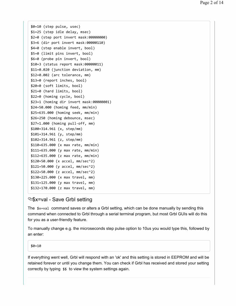
To view the settings, type $$ and press enter after connecting to Grbl. Grbl should respond with a list
of the current system settings, as shown in the example below. All of these settings are persistent
and kept in EEPROM, so if you power down, these will be loaded back up the next time you power up
your Arduino.
Page 1 of 14
$0=10 (step pulse, usec)
$1=25 (step idle delay, msec)
$2=0 (step port invert mask:00000000)
$3=6 (dir port invert mask:00000110)
$4=0 (step enable invert, bool)
$5=0 (limit pins invert, bool)
$6=0 (probe pin invert, bool)
$10=3 (status report mask:00000011)
$11=0.020 (junction deviation, mm)
$12=0.002 (arc tolerance, mm)
$13=0 (report inches, bool)
$20=0 (soft limits, bool)
$21=0 (hard limits, bool)
$22=0 (homing cycle, bool)
$23=1 (homing dir invert mask:00000001)
$24=50.000 (homing feed, mm/min)
$25=635.000 (homing seek, mm/min)
$26=250 (homing debounce, msec)
$27=1.000 (homing pulloff, mm)
$100=314.961 (x, step/mm)
$101=314.961 (y, step/mm)
$102=314.961 (z, step/mm)
$110=635.000 (x max rate, mm/min)
$111=635.000 (y max rate, mm/min)
$112=635.000 (z max rate, mm/min)
$120=50.000 (x accel, mm/sec^2)
$121=50.000 (y accel, mm/sec^2)
$122=50.000 (z accel, mm/sec^2)
$130=225.000 (x max travel, mm)
$131=125.000 (y max travel, mm)
$132=170.000 (z max travel, mm)
$x=val - Save Grbl setting
The $x=val command saves or alters a Grbl setting, which can be done manually by sending this
command when connected to Grbl through a serial terminal program, but most Grbl GUIs will do this
for you as a user-friendly feature.
To manually change e.g. the microseconds step pulse option to 10us you would type this, followed by
an enter:
$0=10
If everything went well, Grbl will respond with an 'ok' and this setting is stored in EEPROM and will be
retained forever or until you change them. You can check if Grbl has received and stored your setting
correctly by typing $$ to view the system settings again.
Page 2 of 14
Grbl's $x=val settings and what they meanNOTE: Settings numbering has changed since v0.8c for future-proofing purposes.
$0 – Step pulse, microseconds
Stepper drivers are rated for a certain minimum step pulse length. Check the data sheet or just try
some numbers. You want the shortest pulses the stepper drivers can reliably recognize. If the pulses
are too long, you might run into trouble when running the system at very high feed and pulse rates,
because the step pulses can begin to overlap each other. We recommend something around 10
microseconds, which is the default value.
$1 - Step idle delay, msec
Every time your steppers complete a motion and come to a stop, Grbl will delay disabling the
steppers by this value. OR, you can always keep your axes enabled (powered so as to hold position)
by setting this value to the maximum 255 milliseconds. Again, just to repeat, you can keep all axes
always enabled by setting $1=255 .
The stepper idle lock time is the time length Grbl will keep the steppers locked before disabling.
Depending on the system, you can set this to zero and disable it. On others, you may need 25-50
milliseconds to make sure your axes come to a complete stop before disabling. This is to help
account for machine motors that do not like to be left on for long periods of time without doing
something. Also, keep in mind that some stepper drivers don't remember which micro step they
stopped on, so when you re-enable, you may witness some 'lost' steps due to this. In this case, just
keep your steppers enabled via $1=255 .
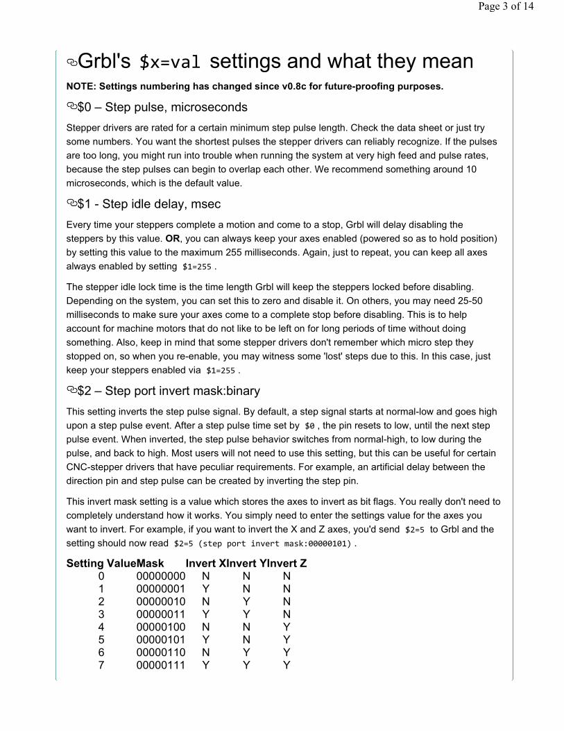
$2 – Step port invert mask:binary
This setting inverts the step pulse signal. By default, a step signal starts at normal-low and goes high
upon a step pulse event. After a step pulse time set by $0 , the pin resets to low, until the next step
pulse event. When inverted, the step pulse behavior switches from normal-high, to low during the
pulse, and back to high. Most users will not need to use this setting, but this can be useful for certain
CNC-stepper drivers that have peculiar requirements. For example, an artificial delay between the
direction pin and step pulse can be created by inverting the step pin.
This invert mask setting is a value which stores the axes to invert as bit flags. You really don't need to
completely understand how it works. You simply need to enter the settings value for the axes you
want to invert. For example, if you want to invert the X and Z axes, you'd send $2=5 to Grbl and the
setting should now read $2=5 (step port invert mask:00000101) .
Setting ValueMask Invert XInvert YInvert Z0 00000000 N N N1 00000001 Y N N2 00000010 N Y N3 00000011 Y Y N4 00000100 N N Y5 00000101 Y N Y6 00000110 N Y Y7 00000111 Y Y Y
Page 3 of 14
$3 – Direction port invert mask:binary
This setting inverts the direction signal for each axis. By default, Grbl assumes that the axes move in
a positive direction when the direction pin signal is low, and a negative direction when the pin is high.
Often, axes don't move this way with some machines. This setting will invert the direction pin signal
for those axes that move the opposite way.
This invert mask setting works exactly like the step port invert mask and stores which axes to invert
as bit flags. To configure this setting, you simply need to send the value for the axes you want to
invert. Use the table above. For example, if want to invert the Y axis direction only, you'd send $3=2
to Grbl and the setting should now read $3=2 (dir port invert mask:00000010)
$4 - Step enable invert, bool
By default, the stepper enable pin is high to disable and low to enable. If your setup needs the
opposite, just invert the stepper enable pin by typing $4=1 . Disable with $4=0 . (May need a power
cycle to load the change.)
$5 - Limit pins invert, bool
By default, the limit pins are held normally-high with the Arduino's internal pull-up resistor. When a
limit pin is low, Grbl interprets this as triggered. For the opposite behavior, just invert the limit pins by
typing $5=1 . Disable with $5=0 . You may need a power cycle to load the change.
NOTE: If you invert your limit pins, you will need an external pull-down resistor wired in to all of the
limit pins to prevent overloading the pins with current and frying them.
$6 - Probe pin invert, bool
By default, the probe pin is held normally-high with the Arduino's internal pull-up resistor. When the
probe pin is low, Grbl interprets this as triggered. For the opposite behavior, just invert the probe pin
by typing $6=1 . Disable with $6=0 . You may need a power cycle to load the change.
NOTE: If you invert your probe pin, you will need an external pull-down resistor wired in to the probe
pin to prevent overloading it with current and frying it.
$10 - Status report mask:binary
This setting determines what Grbl real-time data it reports back to the user when a '?' status report is
sent. By default, Grbl will send back its running state (can't be turned off), machine position, and work
position (machine position with coordinate offsets and other offsets applied). Three additional
reporting features are available that are useful for interfaces or users setting up their machines, which
include the serial RX buffer, planner block buffer usage, and limit pin states (as high or low, shown in
the order ZYX).
To set them, use the table below to determine what data you'd like Grbl to send back. Select the
report types you'd like to see in the status reports and add their values together. This is the value you
use to send to Grbl. For example, if you need machine and work positions, add the values 1 and 2
and send Grbl $10=3 to set it. Or, if you need machine position only and limit pin state, add the
values 1 and 16 and send Grbl $10=17 .
Page 4 of 14
In general, keep this real-time status data to a minimum, since it takes resources to print and send
this data back at a high rate. For example, limit pins reporting is generally only needed when users
are setting up their machine. Afterwards, it's recommended to disable it, as it isn't very useful once
you've got everything figured out.
Report Type ValueMachine Position 1
Work Position 2Planner Buffer 4
RX Buffer 8Limit Pins 16
$11 - Junction deviation, mm
Junction deviation is used by the acceleration manager to determine how fast it can move through
line segment junctions of a G-code program path. For example, if the G-code path has a sharp 10
degree turn coming up and the machine is moving at full speed, this setting helps determine how
much the machine needs to slow down to safely go through the corner without losing steps.
How we calculate it is a bit complicated, but, in general, higher values gives faster motion through
corners, while increasing the risk of losing steps and positioning. Lower values makes the
acceleration manager more careful and will lead to careful and slower cornering. So if you run into
problems where your machine tries to take a corner too fast, decrease this value to make it slow
down when entering corners. If you want your machine to move faster through junctions, increase this
value to speed it up. For curious people, hit this link (http://t.co/KQ5BvueY) to read about Grbl's
cornering algorithm, which accounts for both velocity and junction angle with a very simple, efficient,
and robust method.
$12 – Arc tolerance, mm
Grbl renders G2/G3 circles, arcs, and helices by subdividing them into teeny tiny lines, such that the
arc tracing accuracy is never below this value. You will probably never need to adjust this setting,
since 0.002mm is well below the accuracy of most all CNC machines. But if you find that your circles
are too crude or arc tracing is performing slowly, adjust this setting. Lower values give higher
precision but may lead to performance issues by overloading Grbl with too many tiny lines.
Alternately, higher values traces to a lower precision, but can speed up arc performance since Grbl
has fewer lines to deal with.
For the curious, arc tolerance is defined as the maximum perpendicular distance from a line segment
with its end points lying on the arc, aka a chord. With some basic geometry, we solve for the length of
the line segments to trace the arc that satisfies this setting. Modeling arcs in this way is great,
because the arc line segments automatically adjust and scale with length to ensure optimum arc
tracing performance, while never losing accuracy.
$13 - Report inches, bool
Grbl has a real-time positioning reporting feature to provide a user feedback on where the machine is
exactly at that time, as well as, parameters for coordinate offsets and probing. By default, it is set to
report in mm, but by sending a $13=1 command, you send this boolean flag to true and these
reporting features will now report in inches. $13=0 to set back to mm.
Page 5 of 14
$20 - Soft limits, bool
Soft limits is a safety feature to help prevent your machine from traveling too far and beyond the limits
of travel, crashing or breaking something expensive. It works by knowing the maximum travel limits
for each axis and where Grbl is in machine coordinates. Whenever a new G-code motion is sent to
Grbl, it checks whether or not you accidentally have exceeded your machine space. If you do, Grbl
will issue an immediate feed hold wherever it is, shutdown the spindle and coolant, and then set the
system alarm indicating the problem. Machine position will be retained afterwards, since it's not due
to an immediate forced stop like hard limits.
NOTE: Soft limits requires homing to be enabled and accurate axis maximum travel settings, because
Grbl needs to know where it is. $20=1 to enable, and $20=0 to disable.
$21 - Hard limits, bool
Hard limit work basically the same as soft limits, but use physical switches instead. Basically you wire
up some switches (mechanical, magnetic, or optical) near the end of travel of each axes, or where
ever you feel that there might be trouble if your program moves too far to where it shouldn't. When
the switch triggers, it will immediately halt all motion, shutdown the coolant and spindle (if connected),
and go into alarm mode, which forces you to check your machine and reset everything.
To use hard limits with Grbl, the limit pins are held high with an internal pull-up resistor, so all you
have to do is wire in a normally-open switch with the pin and ground and enable hard limits with
$21=1 . (Disable with $21=0 .) We strongly advise taking electric interference prevention measures. If
you want a limit for both ends of travel of one axes, just wire in two switches in parallel with the pin
and ground, so if either one of them trips, it triggers the hard limit.
Keep in mind, that a hard limit event is considered to be critical event, where steppers immediately
stop and will have likely have lost steps. Grbl doesn't have any feedback on position, so it can't
guarantee it has any idea where it is. So, if a hard limit is triggered, Grbl will go into an infinite loop
ALARM mode, giving you a chance to check your machine and forcing you to reset Grbl. Remember
it's a purely a safety feature.
$22 - Homing cycle, bool
Ahh, homing. For those just initiated into CNC, the homing cycle is used to accurately and precisely
locate a known and consistent position on a machine every time you start up your Grbl between
sessions. In other words, you know exactly where you are at any given time, every time. Say you start
machining something or are about to start the next step in a job and the power goes out, you re-start
Grbl and Grbl has no idea where it is. You're left with the task of figuring out where you are. If you
have homing, you always have the machine zero reference point to locate from, so all you have to do
is run the homing cycle and resume where you left off.
To set up the homing cycle for Grbl, you need to have limit switches in a fixed position that won't get
bumped or moved, or else your reference point gets messed up. Usually they are setup in the farthest
point in +x, +y, +z of each axes. Wire your limit switches in with the limit pins and ground, just like
with the hard limits, and enable homing. If you're curious, you can use your limit switches for both
hard limits AND homing. They play nice with each other.
Page 6 of 14
By default, Grbl's homing cycle moves the Z-axis positive first to clear the workspace and then moves
both the X and Y-axes at the same time in the positive direction. To set up how your homing cycle
behaves, there are more Grbl settings down the page describing what they do (and compile-time
options as well.)
Also, one more thing to note, when homing is enabled. Grbl will lock out all G-code commands until
you perform a homing cycle. Meaning no axes motions, unless the lock is disabled ($X) but more on
that later. Most, if not all CNC controllers, do something similar, as it is mostly a safety feature to
prevent users from making a positioning mistake, which is very easy to do and be saddenee when a
mistake ruins a part. If you find this annoying or find any weird bugs, please let us know and we'll try
to work on it so everyone is happy. :)
NOTE: Check out config.h for more homing options for advanced users. You can disable the homing
lockout at startup, configure which axes move first during a homing cycle and in what order, and
more.
$23 - Homing dir invert mask, int:binary
By default, Grbl assumes your homing limit switches are in the positive direction, first moving the
z-axis positive, then the x-y axes positive before trying to precisely locate machine zero by going back
and forth slowly around the switch. If your machine has a limit switch in the negative direction, the
homing direction mask can invert the axes' direction. It works just like the step port invert and
direction port invert masks, where all you have to do is send the value in the table to indicate what
axes you want to invert and search for in the opposite direction.
$24 - Homing feed, mm/min
The homing cycle first searches for the limit switches at a higher seek rate, and after it finds them, it
moves at a slower feed rate to home into the precise location of machine zero. Homing feed rate is
that slower feed rate. Set this to whatever rate value that provides repeatable and precise machine
zero locating.
$25 - Homing seek, mm/min
Homing seek rate is the homing cycle search rate, or the rate at which it first tries to find the limit
switches. Adjust to whatever rate gets to the limit switches in a short enough time without crashing
into your limit switches if they come in too fast.
$26 - Homing debounce, ms
Whenever a switch triggers, some of them can have electrical/mechanical noise that actually 'bounce'
the signal high and low for a few milliseconds before settling in. To solve this, you need to debounce
the signal, either by hardware with some kind of signal conditioner or by software with a short delay to
let the signal finish bouncing. Grbl performs a short delay, only homing when locating machine zero.
Set this delay value to whatever your switch needs to get repeatable homing. In most cases, 5-25
milliseconds is fine.
$27 - Homing pull-off, mm
Page 7 of 14
To play nice with the hard limits feature, where homing can share the same limit switches, the homing
cycle will move off all of the limit switches by this pull-off travel after it completes. In other words, it
helps to prevent accidental triggering of the hard limit after a homing cycle.
$100, $101 and $102 – [X,Y,Z] steps/mm
Grbl needs to know how far each step will take the tool in reality. To calculate steps/mm for an axis of
your machine you need to know:
• The mm traveled per revolution of your stepper motor. This is dependent on your belt drive
gears or lead screw pitch.
• The full steps per revolution of your steppers (typically 200)
• The microsteps per step of your controller (typically 1, 2, 4, 8, or 16). Tip: Using high microstep
values (e.g., 16) can reduce your stepper motor torque, so use the lowest that gives you the
desired axis resolution and comfortable running properties.
The steps/mm can then be calculated like this: steps_per_mm =
(steps_per_revolution*microsteps)/mm_per_rev
Compute this value for every axis and write these settings to Grbl.
$110, $111 and $112 – [X,Y,Z] Max rate, mm/min
This sets the maximum rate each axis can move. Whenever Grbl plans a move, it checks whether or
not the move causes any one of these individual axes to exceed their max rate. If so, it'll slow down
the motion to ensure none of the axes exceed their max rate limits. This means that each axis has its
own independent speed, which is extremely useful for limiting the typically slower Z-axis.
The simplest way to determine these values is to test each axis one at a time by slowly increasing
max rate settings and moving it. For example, to test the X-axis, send Grbl something like G0 X50
with enough travel distance so that the axis accelerates to its max speed. You'll know you've hit the
max rate threshold when your steppers stall. It'll make a bit of noise, but shouldn't hurt your motors.
Enter a setting a 10-20% below this value, so you can account for wear, friction, and the mass of your
workpiece/tool. Then, repeat for your other axes.
NOTE: This max rate setting also sets the G0 seek rates.
$120, $121, $122 – [X,Y,Z] Acceleration, mm/sec^2
This sets the axes acceleration parameters in mm/second/second. Simplistically, a lower value
makes Grbl ease slower into motion, while a higher value yields tighter moves and reaches the
desired feedrates much quicker. Much like the max rate setting, each axis has its own acceleration
value and are independent of each other. This means that a multi-axis motion will only accelerate as
quickly as the lowest contributing axis can.
Again, like the max rate setting, the simplest way to determine the values for this setting is to
individually test each axis with slowly increasing values until the motor stalls. Then finalize your
acceleration setting with a value 10-20% below this absolute max value. This should account for
wear, friction, and mass inertia. We highly recommend that you dry test some G-code programs with
your new settings before committing to them. Sometimes the loading on your machine is different
when moving in all axes together.
Page 8 of 14
$130, $131, $132 – [X,Y,Z] Max travel, mm
This sets the maximum travel from end to end for each axis in mm. This is only useful if you have soft
limits (and homing) enabled, as this is only used by Grbl's soft limit feature to check if you have
exceeded your machine limits with a motion command.
Grbl's Other '$' CommandsThe other $ commands provide additional controls for the user, such as printing feedback on the
current G-code parser modal state or running the homing cycle. This section explains what these
commands are and how to use them.
$# - View gcode parameters
G-code parameters store the coordinate offset values for G54-G59 work coordinates, G28/G30 pre-
defined positions, G92 coordinate offset, tool length offsets, and probing (not officially, but we added
here anyway). Most of these parameters are directly written to EEPROM anytime they are changed
and are persistent. Meaning that they will remain the same, regardless of power-down, until they are
explicitly changed. The non-persistent parameters, which will are not retained when reset or power-
cycled, are G92, G43.1 tool length offsets, and the G38.2 probing data.
G54-G59 work coordinates can be changed via the G10 L2 Px or G10 L20 Px command defined by
the NIST gcode standard and the EMC2 (linuxcnc.org) standard. G28/G30 pre-defined positions can
be changed via the G28.1 and the G30.1 commands, respectively.
When $# is called, Grbl will respond with the stored offsets from machine coordinates for each
system as follows. TLO denotes tool length offset, and PRB denotes the coordinates of the last
probing cycle.
[G54:4.000,0.000,0.000]
[G55:4.000,6.000,7.000]
[G56:0.000,0.000,0.000]
[G57:0.000,0.000,0.000]
[G58:0.000,0.000,0.000]
[G59:0.000,0.000,0.000]
[G28:1.000,2.000,0.000]
[G30:4.000,6.000,0.000]
[G92:0.000,0.000,0.000]
[TLO:0.000,0.000,0.000]
[PRB:0.000,0.000,0.000]
$G - View gcode parser state
This command prints all of the active gcode modes in Grbl's G-code parser. When sending this
command to Grbl, it will reply with something like:
[G0 G54 G17 G21 G90 G94 M0 M5 M9 T0 S0.0 F500.0]
Page 9 of 14
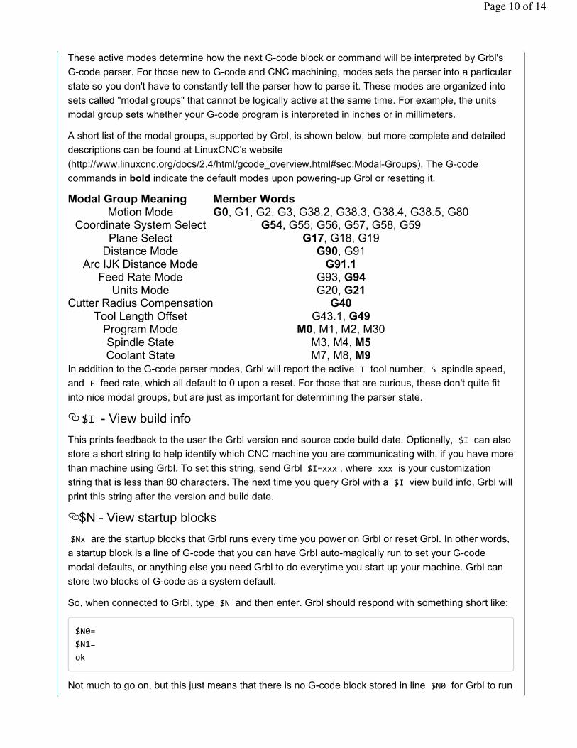
These active modes determine how the next G-code block or command will be interpreted by Grbl's
G-code parser. For those new to G-code and CNC machining, modes sets the parser into a particular
state so you don't have to constantly tell the parser how to parse it. These modes are organized into
sets called "modal groups" that cannot be logically active at the same time. For example, the units
modal group sets whether your G-code program is interpreted in inches or in millimeters.
A short list of the modal groups, supported by Grbl, is shown below, but more complete and detailed
descriptions can be found at LinuxCNC's website
(http://www.linuxcnc.org/docs/2.4/html/gcode_overview.html#sec:Modal-Groups). The G-code
commands in bold indicate the default modes upon powering-up Grbl or resetting it.
Modal Group Meaning Member WordsMotion Mode G0, G1, G2, G3, G38.2, G38.3, G38.4, G38.5, G80