28
Standard and GRBL Gcode Generator for Image Engraving February 2015 Photo courtesy of Mr. Jeffery Woodcock.
| Date post: | 04-Jun-2018 |
| Category: |
Documents |
| Upload: | phunghuong |
| View: | 314 times |
| Download: | 6 times |

Standard and GRBL Gcode Generator
for
Image Engraving
February 2015
Photo courtesy of Mr. Jeffery Woodcock.
Acknowledgments
PicEngrave Pro 5 has been written and developed to convert images to gcode for engraving with
a variety of different methods with cnc machines equipped with either rotary spindles or lasers.
A special acknowledgment is made of the contributions of Mr. Jeffery Woodcock, master
machinist, inventor, and highly skilled artisan, who doggedly invented, developed, and pioneered
the use of low power laser diodes to engrave true gray scale images in various materials, which
has never been done, and in a way that is impossible to do, with high powered CO2 and similar
gas discharge lasers.
Jeff’s laser diode engraving method is truly unique in the both the cnc and art worlds, and
without his willingness to freely share information and his invaluable advice, this software would
not now be available to those who desire to participate in his new, modern form of creating art.
Special appreciation is also due to Mr. Dave Gabry, who designed a unique, yet simple to build,
electronic circuit to convert cnc stepper control signals (as output by Mach3, Linuxcnc, and other
cnc controller programs) into an analog signal for the modulation of laser diodes, as described
later in this paper. Dave’s circuit, and its unique use, is a first, too, having not been previously
done by any others as far as is known to this author.
More information and examples from these two pioneering gentlemen may be found posted on
various internet forums, most notably of which are:
ArtSoft (http://www.machsupport.com/forum/index.php/topic,23584.0.html)
Vectric (http://www.vectric.com/forum/viewtopic.php?f=16&t=13405)
Hobbycncart (http://hobbycncart.com/forum/63-151-4)
And lastly, though far from least, my special appreciation goes to my wife, life partner, and
mother of my children for her limitless love, patience, and understanding of my long hours
locked away in my office and shop writing and testing this program.
John Champlain
February 2015
PicEngrave Pro 5 2
Instructions
PicEngrave Pro 5 (PEP5), +Laser, will generate a gcode file from five popular image file types, either color or gray scale. Supported file types are: jpg, bmp, png, gif, and tif. Original program
© July 28, 2004. All Rights Reserved.******************************************************************************
Image File Selection
The 'Select Image' button opens up a standard MS Windows file directory window. Select an
image file and click 'Open'. The image will be displayed on screen along with buttons for various
functions.
If the 'Cancel' button is clicked without an image being selected, a pop up message will display.
Click 'OK' and repeat the selection process, or exit the program.
The selection process may be repeated at any time as long as the 'Select Image' button is
displayed.
If PEP5 is being used in demo mode, all images will be watermarked. Upon verification of
purchase via www.picengrave.com, a registration key code will be emailed to you. Enter the
registration info using the 'Register Program' button, and then reselect an image and the
watermarks will be removed. You may use the same registration key code to install and register
the program on all computers that you own and/or personally use.
Please note: If you do not receive the registration email within a couple of days following
purchase completion, please make sure you did enter your email address correctly, or check your
email spam folder.
******************************************************************************
Image Selection and Preparation
PEP5 has some basic editing features to allow you to adjust your images to improve your
engravings. There are many good programs available with additional editing features should you
desire to do more than is possible with PEP5. Two of our favorite free photo editors are: GIMP
(http://www.gimp.org/), and: Irfanview (http://www.irfanview.com/).
When editing an image for engraving, some experimentation may be needed for best results.
Color images can be viewed in gray scale by selecting the 'View Gray Scale' check box. This will
assist you in more closely judging what your final engraved image will look like.
Hint: Some images, especially those scanned from a print or film, may exhibit small "white
marks" randomly scattered throughout the image. These are usually caused by dust on the
surface of the scanner glass, and/or scratches and other damage in the original print. If you are
PicEngrave Pro 5 3
engraving lithophanes, these "white marks" will be magnified by the size and shape of your
engraving bit. For better results, they should be retouched using your favorite image editor's
tools before you proceed to generate a gcode file. Using sharp pointed engraving bits with
shallow angles (less than 30°) can help to minimize this issue with lithophanes.
******************************************************************************
Rotate Image and Flip Image
After an image has been selected, and before it is loaded for conversion, it may be rotated
and/or flipped to re-orient it. The 'Rotate Image' button will rotate the image 90° to the right
each time it is clicked, and the 'Flip Image' button will flip the image horizontally.
******************************************************************************
Loading an Image
With an image displayed on screen, clicking the 'Load Image' button will load the file into your
computer's memory and prepare it for conversion to gcode.
******************************************************************************
Generating Gcode
After an image has been loaded, a 'Generate Gcode' button will appear. When clicked, this
button begins the actual generation of the gcode file. The 'Generate Gcode' button will
disappear at the end of this process. You may still repeat the image selection process, or proceed
to the next step.
Please Note: In some modes, PEP5 will optimize the gcode to eliminate some unneeded gcode
lines where the 3rd axis (Z) depth is not changing. This is accomplished by the use of a
proprietary and unique gcode generation algorithm that will not reduce the resolution of your
final engraved images. The final gcode can be significantly smaller (depending upon the initial
image) and will run faster than gcode produced by other competing programs. This optimization
will be done with a different algorithm if laser gcode is being generated.
******************************************************************************
Saving a Gcode File
When the 'Save Gcode' button appears, clicking it will generate and save a gcode file to a
preselected folder on your computer. PEP5 will not overwrite a previous file without warning.
'File Extension' should be changed to suit your cnc controller gcode file naming requirements.
The name of the gcode file can be entered when you save a gcode file.
PicEngrave Pro 5 4
'Gcode Directory’ This is used to determine where the gcode file will be saved on your
computer. If the file directory does not exist, it will be created by your MS Windows operating
system when you save the gcode.
******************************************************************************
Program Configuration Settings
When visible, the 'Show (Hide) Settings' button will allow you to select or change picture
engraving parameters. Settings may be changed at any time until the 'Generate Gcode' button
appears.
Choose Engraving Profile
PEP5 allows you to save your customized configuration settings in six different profiles for later
reuse. The profiles are saved on your computer as plain text files with a file extension of '.ini'.
When a profile is selected, the last settings saved for that profile will be automatically loaded
and used to setup and generate the gcode files. After changing any setting, the profile is
updated by clicking on the 'Save Settings' button. If you change a setting, but do not wish to
change the saved profile, click on the 'Hide Settings' or the 'Close' button, and the profile will
not be saved to your computer, but the changed setting will be still used to generate the gcode
for that session. Selecting a profile will display the settings that are available for setting up that
particular profile, and will hide those settings that cannot be used.
CAUTION: Manually modifying the profile files may cause PEP5 to malfunction.
******************************************************************************
Gcode Setup
'Metric Mode'
Enabling this option will clear all setting and setup PEP5 to work in metric units. If you
accidentally clicked this option, do not click the 'Save and Close' button, unclick the metric
option, then reselect the profile you want to use, and your previous settings should be restored.
'Feed Rate’ Enter a number that is suitable for your machine and the material you are engraving.
It is recommended that you start out with a slower rate until you see how your machine
responds to engraving operations, and then increase the rate until you achieve acceptable
performance.
'Pixel Resolution' sets the engraved pixel size of your images, and is the distance that the X and Y
axes move between pixels and scan lines. It affects the final size of an engraved image. The
default resolution for all images is 0.010 inch / 0.254 mm.
PicEngrave Pro 5 5

'Max. 3rd Axis Depth' determines how deep black colors will be engraved. If the colors have
been reversed by the 'Lithophane Gcode/Negative Colors' option, then white colors will be the
deepest. The correct depth for engraving will vary depending upon the engraved material type,
bit style and size, and other engraving and machine setting parameters. In some cases this
setting must be a negative number. Experimentation is needed to determine what works best
for your engravings. For lithophanes, a depth of minus 0.1 inch is a good starting value for
DuPont Corian and similar materials with a total thickness of about 0.15 inches.
'Min. 3rd Axis Depth’ is used to set the shallowest depth of an engraving, and in some cases also
needs to be a negative number that is less than the ‘Max. 3rd Axis Depth’ value. It is usually
used to compensate for surface height variations in the material being engraved, and sets the
“zero” point of the engraving depth. Normally it should be set to 0.0.
Note: all engraving depths are negative with reference to the top surface (Z0) of the engraved
material.
'3rd Axis (Z) Safe Position' should be set so the tool bit will clear the upper surface of your work
piece and any fixture clamps or other obstructions. For laser engraving it is usually set to 0.0.
'X Start Position' and 'Y Start Position' determine the offset from the initial image zero (X0/Y0)
position you have selected for an engraved image.
******************************************************************************
Gcode Options
'Insert G61/64' is included so Mach3 users can select Exact Stop (G61) mode and turn off
Constant Velocity (CV) mode (G64) when a straight sided edge is to be engraved. This will
minimize the rounding of edge corners sometime caused by a Mach3 CV setting. Using CV mode
during actual image engraving will reduce engraving time and smooth out machine movements.
'Spindle On/Off' inserts M03 and M05 commands to start and stop your engraving spindle/laser
relay if your controller is set up for automatic control.
'Comment Gcode' will record key engraving parameters and options to the beginning of each
gcode file for future reference.
'Start Comments' and 'End Comments' are characters used by your gcode controller program to
indicate program comments that are not actual gcode control commands. Refer to your
controller documentation to properly enter these characters.
'End w/ G28' will insert a G28 gcode command as the last command in a gcode file. It is used by
some Arduino GRBL controllers in place of Mach3's M30.
PicEngrave Pro 5 6
'Axis Letters' may be set to your choice of 'A', 'B', 'C', 'F', 'S', 'X', 'Y', or 'Z', depending upon the
engraving profile and other options you have chosen.
'Initial Image Zero' sets either the lower left, or the center, of your image as the initial X0/Y0
starting point.
'Precode' and 'Postcode' buttons allow the inclusion of specific gcodes that may be required for
your controller program to operate properly. Click on the buttons to manually enter your codes.
When the 'Close' button is clicked, your codes will be saved to a file for use each time the
program runs.
******************************************************************************
Engraving Angles
These settings determine the path angle your spindle or laser will traverse when engraving.
When allowable, the 'Left - 45°', 'Right - 45°', 'Horizontal', and 'Vertical' angles may all be
selected (or any combination of them) at the same time. Selecting more than one of these
options will increase both the size of the gcode file and the total engraving time, but doing so
may also improve your image's engraved quality. Some angles are not available for some
engraving profiles.
'Horizontal 2X' and 'Vertical 2X' check boxes will double the normal number of engraved lines
for a finer engraving resolution, without affecting the finished engraved image size. Only one 2X
option can be selected at a time, and not in combination with any other angle option. Selecting
either of the 2X options will unselect the other angle options. As an example, if the 'Pixel
Resolution' is set to 0.01 inch, then the 2X angle options will engrave an image with a line-to-line
spacing of 0.005 inches while maintaining a pixel-to-pixel spacing on each line at 0.01 inches.
This can be especially useful to improve the engraved quality and details of lithophanes.
******************************************************************************
Engraving Options
'Engrave Ellipse' option will allow you to select an area of the picture to be engraved within an
elliptical or circular shape that you set and position with the slider controls. All pixels of an
image that are outside the ellipse will be ignored when the gcode is generated. The X0/Y0
reference points of the gcode will be set to the left side and bottom edge intersection point of
the ellipse if the 'Initial Image Zero' option is set to the 'Lower Left' of the image, and will be
centered within the ellipse if the 'Center' option is selected.
'Ellipse Edge' when selected will engrave an elliptical border to the 'Max. 3rd Axis Depth' if the
'Rotary Spindle' profile is selected. It is not used with laser profiles.
PicEngrave Pro 5 7
'Engrave Edge' will engrave an edge around the perimeter of straight-sided images at a depth
corresponding to the 'Max. 3rd Axis Depth' setting, and at the width of the engraving bit. This
helps in reducing cutting forces on the cutting bit when beginning an image, and reduces the
jagged appearance sometimes caused by the bit around the perimeter of an engraving,
especially a lithophane. Edges are engraved in five passes, each of increasing depth, until the
'Max. 3rd Axis Depth' is reached. This option selection is only usable for rotary spindle
engraving.
'Crop Image' option works similar to the 'Engrave Ellipse' option except it is used to reduce
(crop) the engraved size of straight sided images.
'Edge FR' should be set to use a slower edge engraving feed rate than that used for images to
minimize cutting stresses and bit breakage. This feature is set separately for spindle and laser
engraving.
'Lithophane Gcode/Reverse Colors' option reverses the depth of cut for light and dark pixels of
images for lithophanes and mirrors, which are usually engraved as negative images.
'Skip White Bkgnd', when enabled, skips over the generation of gcode lines for all duplicate
white background pixels, reducing engraving times.
'Use Feed Rate Change' This feature is unique to PEP5, and can be used with both spindle and
laser engraving. When used with spindle engraving, it will reduce bit loading when heavier
(deeper) cuts are made. When used with laser engraving, it will increase the burning of darker
colored pixels.
When enabled, each gcode line will have a feed rate command added to the end. The feed rate
value is calculated with a proprietary formula using the gray scale value of the pixel to be
engraved, and the percentage value entered into the '% Feed Rate Change' text box. A typical
value for laser engraving most wood types will range between 10% and 40%. Some
experimentation will be needed to determine the best value to use. Using this control should
result in a better contrast of laser diode engraved images, and possibly less bit breakage when
spindle engraving.
'Extended Edge' When higher power laser diodes are used at higher feed rates, abrupt axis
direction changes can introduce vibrations in the laser beam at the edges of images, causing the
laser to burn pixels out-of-alignment. Using the extended edge option will reduce power to the
laser to its minimum value, and "extend" the axis movement beyond the edge of the image
before direction reverses. When using this option, be sure to allow for the additional tool travel
distances when you place your work pieces on the machine table.
PicEngrave Pro 5 8

Laser Options
'TTL Laser Gcode' Using TTL control, there are two options. With 'TTL Laser Gcode' unchecked,
the gcode is formatted similar to "Analog Laser" gcode, with X, Y, and Z moves on the same line.
A machine should run smoother with this format. When 'TTL Laser Gcode' is checked, the gcode
is formatted with the Z move on separate line from the X and Y moves. This may result in a
slower machine operation, but may be better for some types of engraving, such as impact.
For TTL engraving, images must first be dithered so they are composed of only two colors,
usually black and white. A dithered image is similar to the halftone images printed in magazines
and newspapers. The dithering algorithms included in PEP5 are used to prepare an image for
TTL laser engraving. As the laser scans across a dithered image, it is either at reduced power, or
fully off, for all white pixels, and is fully on at its preset power for all black pixels. TTL mode is
useful for some materials (such as leather) which burn so easily as to not be able to show well
defined shades of gray. This mode does not require an analog laser driver, so a TTL only driver
can be used with good results.
For a more detailed explanation of dithering, users should read the paper on image dithering
also appended to this document.
'Rapid Retract Height', when set to a positive number, is useful with some types of analog
controllers, such as a rotary encoder. Normally it should be left set to 0.0.
'Laser Edge' engraves an outline around the perimeter of an image at a feed rate set by the
'Laser Feed Rate' value, before laser engraving the image. If the 'Width in Pixels' is set to other
than 1, additional passes will be made around an edge, each offset 1 pixel from the previous
pass.
'Laser Edge Power Command' Enter the command that your system uses to turn on the laser to
the power level desired. Ex: Z-.0255.
'Laser VFR Power Control Commands' set the minimum and maximum laser power commands
that are used when engraving images using a variable feed rate instead of a variable laser power.
VFR mode is useful for gray shade engraving of mirrors, and for engraving gray shade images
with a TTL laser controller.
PicEngrave Pro 5 9

Special Functions
'Align X/Y Axes' PEP5 produces gcode that engraves bi-directionally. Some machines have
excessive backlash will not engrave images well. To improve engraving, PEP5 allows either X or Y
movements to be offset in one movement direction, thus aligning the pixels more accurately.
Once set for a particular machine, the settings will remain in use for every image until changed.
To set, engrave a small dithered image using the TTL profile and adjust the correct axis offset as
determined by observing the placement of the dithered points (pixels) in the image.
'Rotary Axis Setup' This function, when enabled, will generate gcode that can be used with a
4th axis rotary attachment for engraving on cylinders. It will only be optional if the 'Horizontal'
engraving angle is first selected, and only with an "A" axis.
******************************************************************************
'Save Settings' button updates all of your preferred settings to a configuration file on your
computer that is automatically loaded for reuse each time the program starts up. CAUTION:
Configuration files (*.ini) should not be manually edited.
******************************************************************************
Edit Image Button
When the 'Edit Image' button is clicked, a separate program that operates only within PEP5 will
open. This program will allow you to reduce or increase the size of an image, change its aspect
(width-to-height ratio), and adjust its sharpness, brightness, contrast and gamma properties.
Edited images will need to be saved on your computer for subsequent opening in PEP5. It is not
necessary to first open an image in PEP5 in order to use the editing function, but it will be
necessary to 'reselect' an image if it has been edited and saved after having first been selected
and opened in PEP5.
******************************************************************************
Add Text
This is another separate program that runs only within PEP5 to add text to an image. Full control
of the text and font are possible before saving the image. For multi-line text, add each line sepa-
rately to your image.
Hint: For best results, add text only AFTER all other editing is completed.
******************************************************************************
Gray Curve
'Apply Gray Curve' will lighten the mid-range gray shades in an image. This is useful to
compensate for some woods and other materials to over-burn, creating darker engravings. The
PicEngrave Pro 5 10
higher the value set on the slider control, the greater the lightening effect. On large images it
may take a few minutes to finish before the effect can be viewed, especially on slower
computers.
******************************************************************************
Working With Lasers
Laser diodes (LDs) with a power output of between 1 and 2 watts are being used more and more
to engrave very detailed images into various types of wood and other suitable materials with cnc
routers. The LDs replace conventional engraving spindles. This use of LDs with cnc machines is
in its infancy, and new developments are occurring frequently.
Setting up and using LDs requires specialized equipment, knowledge, experience, and safety
precautions to prevent harmful injuries to individuals, animals, and property. The improper and
unsafe operation of high power laser diodes can cause permanent injury to individuals and
animals, and property damage, even at significant distances from the LDs.
Information concerning how to physically setup and use LDs is appended to the end of this
document. Readers are also encouraged to search the Internet for more information on their
availability, lawful use, and, more importantly, their safe use requirements.
Please always work safely, and never apply power to a laser diode without assuring that all
individuals within sight of a powered laser diode are wearing specifically approved laser safety
glasses. Never look at the beam of an LD without wearing special safety glasses, and never,
under any circumstances, aim the beam directly into anyone's eyes, even through safety glasses.
Permanent blindness will result.
Analog Control
With analog control, as the laser scans across the image area, its power will increase and
decrease (modulate) in proportion to the gray shade value of each pixel in the scan line. Higher
power burns darker pixels and lower power burns lighter pixels while the scanning velocity of
the laser remains constant. Analog control requires the use of a digital to analog converter (a
DAC) to generate a varying control voltage that is compatible with some LD controllers
specifically designed to modulate the power to the LD. Commonly a signal range of 0 to 5 volts
DC is used.
Analog control signals can be generated either by an electronic circuit, or by a mechanical
encoder connected to a stepper motor (which is the method developed and very successfully
used by Jeff Woodcock, mentioned earlier in this paper.
PicEngrave Pro 5 11
The electronic DAC accepts step and direction signals directly from the parallel port of a
computer running a cnc controller software program (such as ArtSoft’s Mach3). It then outputs
a signal voltage that is proportional to the number of step signals being output.
Constant power can now be used in two different modes: TTL or VFR (a newly developed
method).
VFR Control
VFR (variable feed rate) control is a newly developed unique method of engraving true gray
shade values. This method can also be used with a laser diode driver that supports only TTL
input if an analog controlled driver is unavailable. The laser power remains constant during a file
run, and the axis speed will change so the laser burns darker at slower speeds for pixels with
darker shades, and moves faster for those with lighter shades. Some versions of Mach3 may not
support variable feed rates on each gcode line, and you may need to upgrade Mach3 to a newer
version for a smooth axis movement.
The use of PEP5 for cnc control of LDs is at the sole risk of the LD owner/operator, and no liability
will be assumed or assigned to PEP5 or its author for any problems that arise from such use.
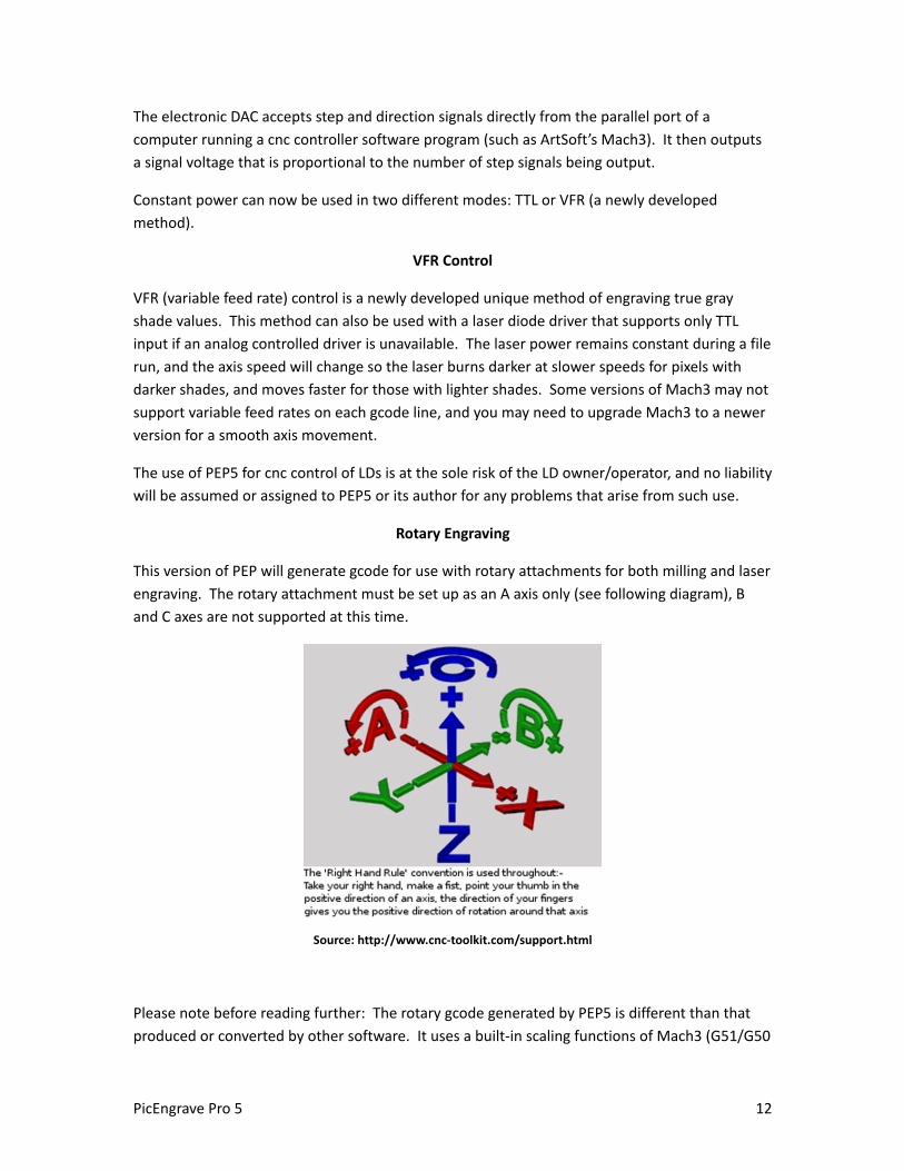
Rotary Engraving
This version of PEP will generate gcode for use with rotary attachments for both milling and laser
engraving. The rotary attachment must be set up as an A axis only (see following diagram), B
and C axes are not supported at this time.
Source: http://www.cnc-toolkit.com/support.html
Please note before reading further: The rotary gcode generated by PEP5 is different than that
produced or converted by other software. It uses a built-in scaling functions of Mach3 (G51/G50
PicEngrave Pro 5 12
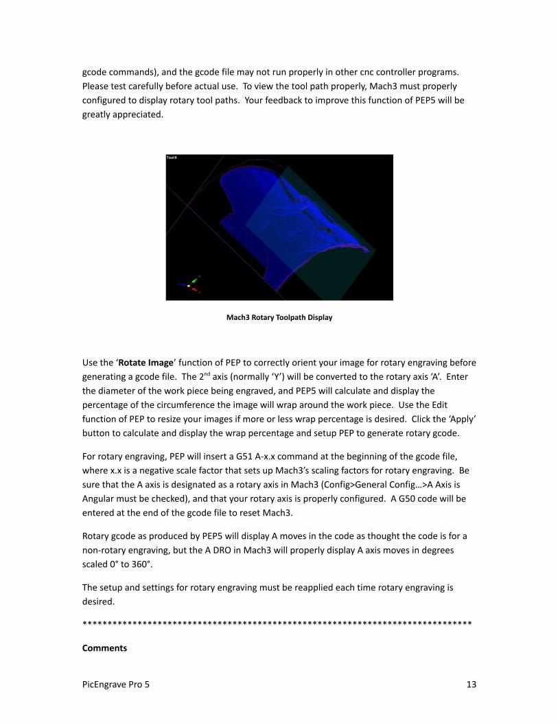
gcode commands), and the gcode file may not run properly in other cnc controller programs.
Please test carefully before actual use. To view the tool path properly, Mach3 must properly
configured to display rotary tool paths. Your feedback to improve this function of PEP5 will be
greatly appreciated.
Mach3 Rotary Toolpath Display
Use the ‘Rotate Image’ function of PEP to correctly orient your image for rotary engraving before
generating a gcode file. The 2nd axis (normally ‘Y’) will be converted to the rotary axis ‘A’. Enter
the diameter of the work piece being engraved, and PEP5 will calculate and display the
percentage of the circumference the image will wrap around the work piece. Use the Edit
function of PEP to resize your images if more or less wrap percentage is desired. Click the ‘Apply’
button to calculate and display the wrap percentage and setup PEP to generate rotary gcode.
For rotary engraving, PEP will insert a G51 A-x.x command at the beginning of the gcode file,
where x.x is a negative scale factor that sets up Mach3’s scaling factors for rotary engraving. Be
sure that the A axis is designated as a rotary axis in Mach3 (Config>General Config…>A Axis is
Angular must be checked), and that your rotary axis is properly configured. A G50 code will be
entered at the end of the gcode file to reset Mach3.
Rotary gcode as produced by PEP5 will display A moves in the code as thought the code is for a
non-rotary engraving, but the A DRO in Mach3 will properly display A axis moves in degrees
scaled 0° to 360°.
The setup and settings for rotary engraving must be reapplied each time rotary engraving is
desired.
******************************************************************************
Comments
PicEngrave Pro 5 13
Hint: a careful observation of the first couple of passes of an engraved edge may reveal whether
or not the surface of the material is flat and even, helping to avoid non-engraved areas when the
3rd axis depth is engraving at a zero depth. This is especially useful when engraving lithophanes.
The engraving bit should always be zeroed to the thinnest part of your material (or slightly
below) for best engraving results.
PicEngrave Pro 5 +Laser is frequently updated as experience and user reports validate reasons
for improvements, and this document may not cover all settings and options of the current
release version. The latest version of PEP5will always be posted here:
http://www.picengrave.com/ .
The feed rate must be higher than zero (0) before a gcode file can be generated.
Never apply power to a laser diode without first assuring that all persons and animals within
sight of the laser are wearing appropriate safety glasses. Laser diodes can instantly and
permanently damage eyesight, and possibly cause total blindness, even if not being viewed
directly should the laser beam be reflected from some surfaces into someone’s eye(s). This can
occur even at a significant distance (possibly miles away) from the laser beam’s source. The
user/operator of any laser equipment assumes all liability for their safe use, and no liability will
be assigned to, or assumed by, the author of this paper or PicEngrave software. Users of
PicEngrave Pro 5 assume all liability for its use. Please work safely and carefully.
******************************************************************************
This software is made available with no guarantees as to its suitability for any use. All risks
remain with the user.
Thank You.
John Champlain and Jeff Woodcock
www.picengrave.com
PicEngrave Pro 5 14
Analog Laser Diode Setup
forGray Scale Image Engraving
www.picengrave.com
A special appreciation goes to Mr. Jeff Woodcock, and his son Jeffery, for their assistance and
photos.
----------------------------------------------------------------
This brief paper describes two control systems (mechanical and electronic) currently in use to
control a 1 to 2 watt, 445 laser diode for image etching.
Safety
The power levels of the laser diodes (and actually all laser diodes, and commonly available laser
pointers as well) that are used for image engraving can be instantly dangerous to the safety and
eyesight of users and bystanders when used recklessly and without proper safety precautions.
All users and others within sight of an operating laser diode, regardless of separation distance,
must at a minimum wear the correct type of safety glasses specified for the laser light
wavelength in use. Suitable safety glasses are available from many sources, and laser diode
owners and users must never operate a laser diode without first assuring that all persons within
the viewable range (which can be a considerable distance away) are properly equipped with, and
wearing, approved safety glasses.
All laser machines should be fully enclosed within a housing specifically designed to completely
prevent the laser beam from being seen by anyone when in operation.
Under no circumstances will the author of this document be held responsible for any injury to
the reader or others, or for any damage to surrounding property. All responsibility for safe laser
diode operations remain with the user.
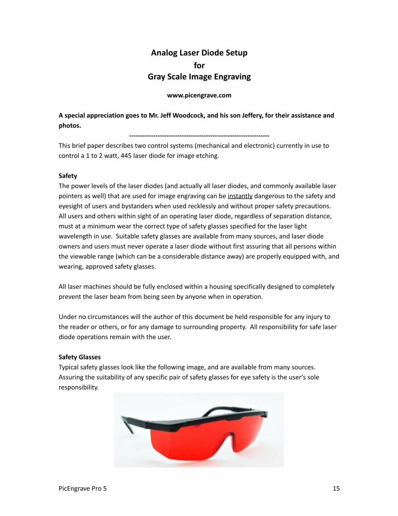
Safety Glasses
Typical safety glasses look like the following image, and are available from many sources.
Assuring the suitability of any specific pair of safety glasses for eye safety is the user's sole
responsibility.
PicEngrave Pro 5 15

Laser Diodes
Laser diodes are available with different wavelengths and characteristics. While some of them
may be suitable for image engraving, the type of laser diode we are using very successfully is the
445nm diode with 1 to 2 watts power rating. These emit a bluish beam that can be focused with
a suitable lens to a dot point that is about 0.005 to 0.007 inches in diameter.
For our use, these diodes must be installed in a suitable housing (below), which has an easily
adjustable focusing lens.
PicEngrave Pro 5 16
If your looking for a complete laser photo engraving solution to use with our software programs,
visit J Tech Photonics website here: jtechphotonics.com

Lenses
445nm Glass Collimating Lens/M9P0.5 Metal Frame
Heat Sinks
Laser diodes produce a lot of heat at the power levels and duration needed for image engraving,
so an adequate heat sink is required.
Typical Heat Sinks
PicEngrave Pro 5 17
Lenses we use to laser engrave photos are the AR coated 3 element glass, or J Tech’s high quality precision
G2 lens. The G2 lens that is included with there laser systems give you 30% more power then the 3 element
glass and will allow you to cut materials, or engrave fine detailed photos.
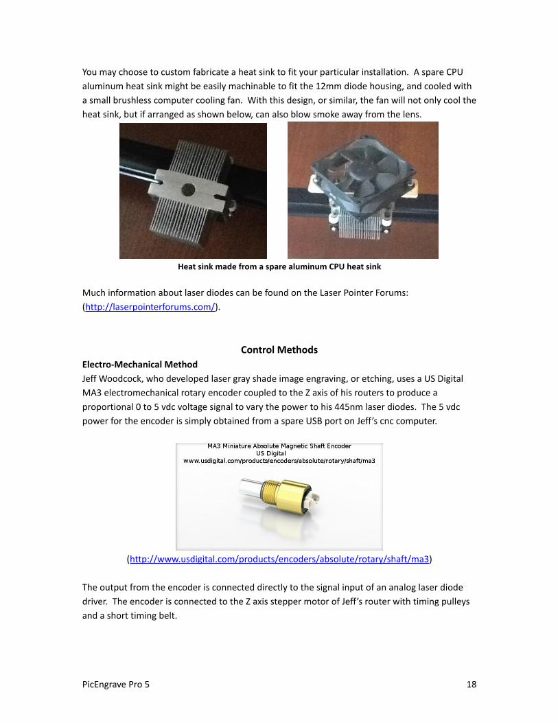
You may choose to custom fabricate a heat sink to fit your particular installation. A spare CPU
aluminum heat sink might be easily machinable to fit the 12mm diode housing, and cooled with
a small brushless computer cooling fan. With this design, or similar, the fan will not only cool the
heat sink, but if arranged as shown below, can also blow smoke away from the lens.
Heat sink made from a spare aluminum CPU heat sink
Much information about laser diodes can be found on the Laser Pointer Forums:
(http://laserpointerforums.com/).
Control Methods
Electro-Mechanical Method
Jeff Woodcock, who developed laser gray shade image engraving, or etching, uses a US Digital
MA3 electromechanical rotary encoder coupled to the Z axis of his routers to produce a
proportional 0 to 5 vdc voltage signal to vary the power to his 445nm laser diodes. The 5 vdc
power for the encoder is simply obtained from a spare USB port on Jeff’s cnc computer.
(http://www.usdigital.com/products/encoders/absolute/rotary/shaft/ma3)
The output from the encoder is connected directly to the signal input of an analog laser diode
driver. The encoder is connected to the Z axis stepper motor of Jeff’s router with timing pulleys
and a short timing belt.
PicEngrave Pro 5 18

An Instructable of Jeff's Shapeoko 2 set up similar to this photo is here:http://www.instructables.com/id/Shapeoko-2-Arduino-UNO-R3-grbl-9g-8bit-Raster-Phot/
In Jeff’s current setup shown in the photo above, the stepper motor pulley has 40 teeth and the encoder pulley has 12 teeth, for a ratio of 3.33:1. The Z axis drive uses a separate set of pulleys with a drive ratio of 2:1, so the Z axis moves only ½ the distance called for in the gcode. This arrangement provides a 0 to 5 volt signal with a Z movement of just -0.0128 inches. This reduction of the Z axis movement prevents any significant change of the laser’s focal point on the material being etched. Jeff’s encoder setup provides 256 encoder positions of 0.0001 inches each, or, in other words, 256 theoretical gray shades in an engraved image.
To burn his images, Jeff sets up PEP4 so the Z axis "Minimum Depth" (image zero point) is at -0.0037 inches from where the encoder output voltage will roll over to 5V (which is where the laser just begins to burn the wood); Jeff zeros the Z axis on his machine there. Then he sets up the "Maximum Depth" in PEP4 to -0.0256 inches. The Z axis "Safe Position" setting is then set to .0035 inches, which gives a safety margin of 0.0002 inches from the position where the encoder will roll over to full on power. With these settings, PEP4 will produce a gcode file with a full 256 shades of gray resolution.
With Jeff’s setup, the Z axis can also be used to set the focal point of the laser for different material thicknesses without needing to manually refocus the laser lens.
To rapidly pulse the laser on and off (for black and white images, or TTL), the Z axis direction pin is reversed so the encoder "jumps" to full output (5 volts) instantly for the black colors of an image, and back to 0 vdc for white. Jeff sets the encoder .0005 inches from the rollover point and zeros the machine's Z axis there and sets up PEP4 with a minimum depth of .0000 inches and maximum depth of -.0015 inches with a safe position of .0005 inches. This allows the encoder connected to an analog laser driver to also work in TTL mode.
PicEngrave Pro 5 19
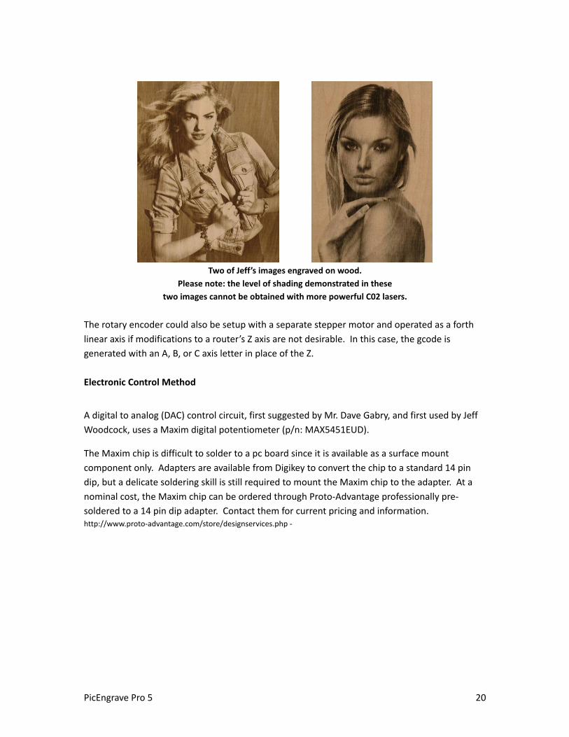
Two of Jeff’s images engraved on wood.
Please note: the level of shading demonstrated in these
two images cannot be obtained with more powerful C02 lasers.
The rotary encoder could also be setup with a separate stepper motor and operated as a forth
linear axis if modifications to a router’s Z axis are not desirable. In this case, the gcode is
generated with an A, B, or C axis letter in place of the Z.
Electronic Control Method
A digital to analog (DAC) control circuit, first suggested by Mr. Dave Gabry, and first used by Jeff
Woodcock, uses a Maxim digital potentiometer (p/n: MAX5451EUD).
The Maxim chip is difficult to solder to a pc board since it is available as a surface mount
component only. Adapters are available from Digikey to convert the chip to a standard 14 pin
dip, but a delicate soldering skill is still required to mount the Maxim chip to the adapter. At a
nominal cost, the Maxim chip can be ordered through Proto-Advantage professionally pre-
soldered to a 14 pin dip adapter. Contact them for current pricing and information.http://www.proto-advantage.com/store/designservices.php -
PicEngrave Pro 5 20
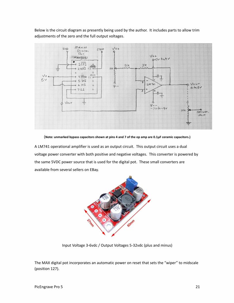
Below is the circuit diagram as presently being used by the author. It includes parts to allow trim
adjustments of the zero and the full output voltages.
(Note: unmarked bypass capacitors shown at pins 4 and 7 of the op amp are 0.1μF ceramic capacitors.)
A LM741 operational amplifier is used as an output circuit. This output circuit uses a dual
voltage power converter with both positive and negative voltages. This converter is powered by
the same 5VDC power source that is used for the digital pot. These small converters are
available from several sellers on EBay.
Input Voltage 3-6vdc / Output Voltages 5-32vdc (plus and minus)
The MAX digital pot incorporates an automatic power on reset that sets the “wiper” to midscale
(position 127).
PicEngrave Pro 5 21
To initialize the circuit for use, a stepper signal corresponding to midscale (in the author’s setup
this is C-0.0127) is manually output to the DAC, followed by applying the supply voltage to the
DAC. Then a step signal of C0.0 is output, after which power can be turned on to the laser diode
control, and engraving operations can begin.
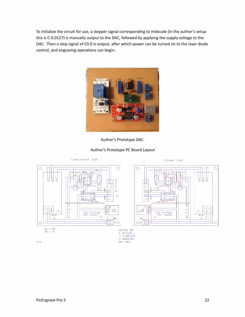
Author’s Prototype DAC.
Author’s Prototype PC Board Layout
PicEngrave Pro 5 22
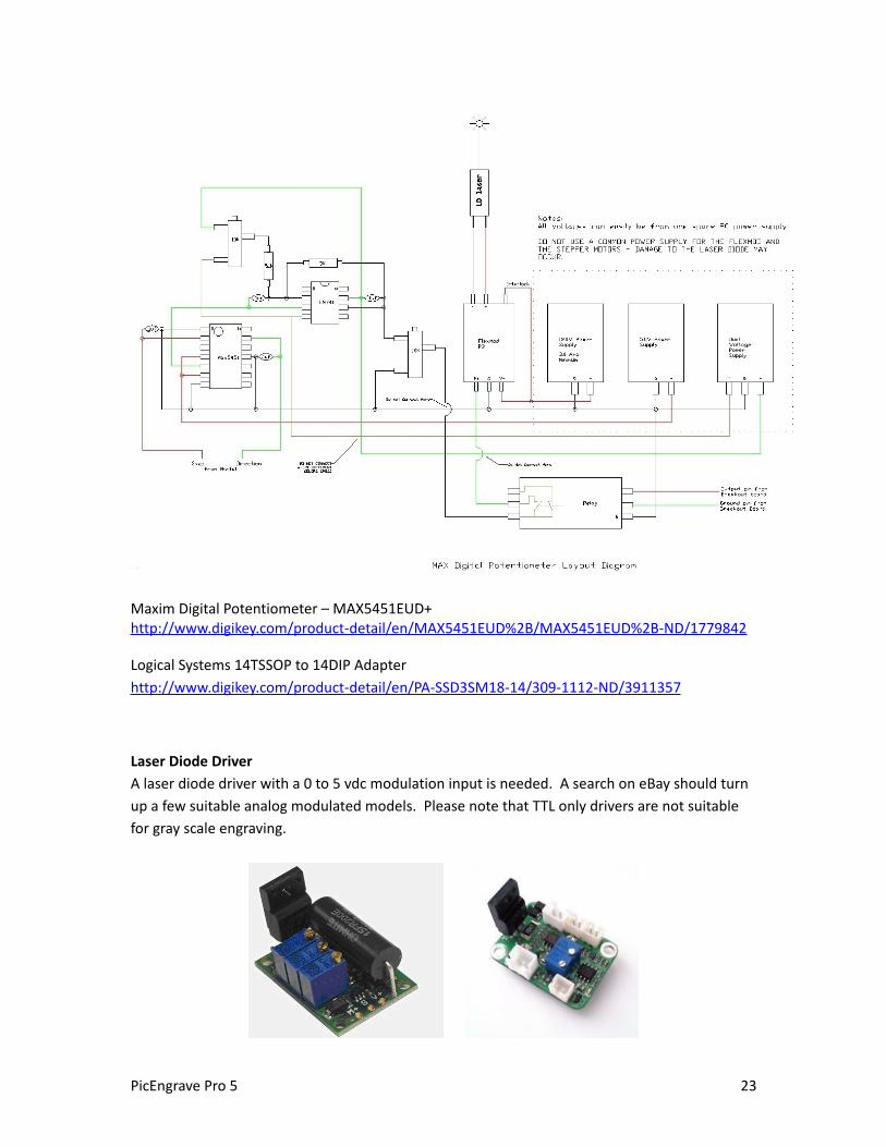
Maxim Digital Potentiometer – MAX5451EUD+http://www.digikey.com/product-detail/en/MAX5451EUD%2B/MAX5451EUD%2B-ND/1779842
Logical Systems 14TSSOP to 14DIP Adapter
http://www.digikey.com/product-detail/en/PA-SSD3SM18-14/309-1112-ND/3911357
Laser Diode Driver
A laser diode driver with a 0 to 5 vdc modulation input is needed. A search on eBay should turn
up a few suitable analog modulated models. Please note that TTL only drivers are not suitable
for gray scale engraving.
PicEngrave Pro 5 23

I also use a small relay circuit so I can turn power on and off to the laser with Mach3 spindle
commands (M03/M05). I have it wired so the 0 to 5 volt signal from the DAC is removed from
the driver input when I want the laser to be completely off. The relay below was purchased from
eBay, and may not be available now, but any similar unit should work.
Mach3 Setup
I use the “C” drive to control my lasers. This leaves the Z axis available to manually raise and
lower the diode to maintain focus for different wood thicknesses, which is very convenient. I
have C velocity and acceleration settings set to maximum, and the ‘steps per’ set to 10,000,
giving a range of 0.0 to -0.0255 steps, in 0.0001 inch increments.
The relay is controlled from a Mach3 output pin using the standard M03/M05 spindle codes.
The Mach3 standard screen can be used for laser diode work, but I prefer my own custom screen
set that allows me the needed flexibility in laser control without the clutter of un-needed
controls.
PicEngrave Pro 5 24

Readers are encouraged to visit this forum ( http://hobbycncart.com/forum/63-151-1 ) to read
more about the use of laser diodes for image engraving. It is an active forum, and new members
are welcomed and encouraged to participate. The freely shared collective experiences of forum
members can make it much easier for beginners to avoid costly mistakes when setting up a laser
diode engraving system. My very special appreciations also to good friend, Tweakie, to whom I
give credit with getting me interested in laser diode image engraving originally. (
http://www.cooperman.talktalk.net/ )
Work Safe, and Enjoy,
John Champlain
http://www.picengrave.com/
Last revision: February 2015
PicEngrave Pro 5 25
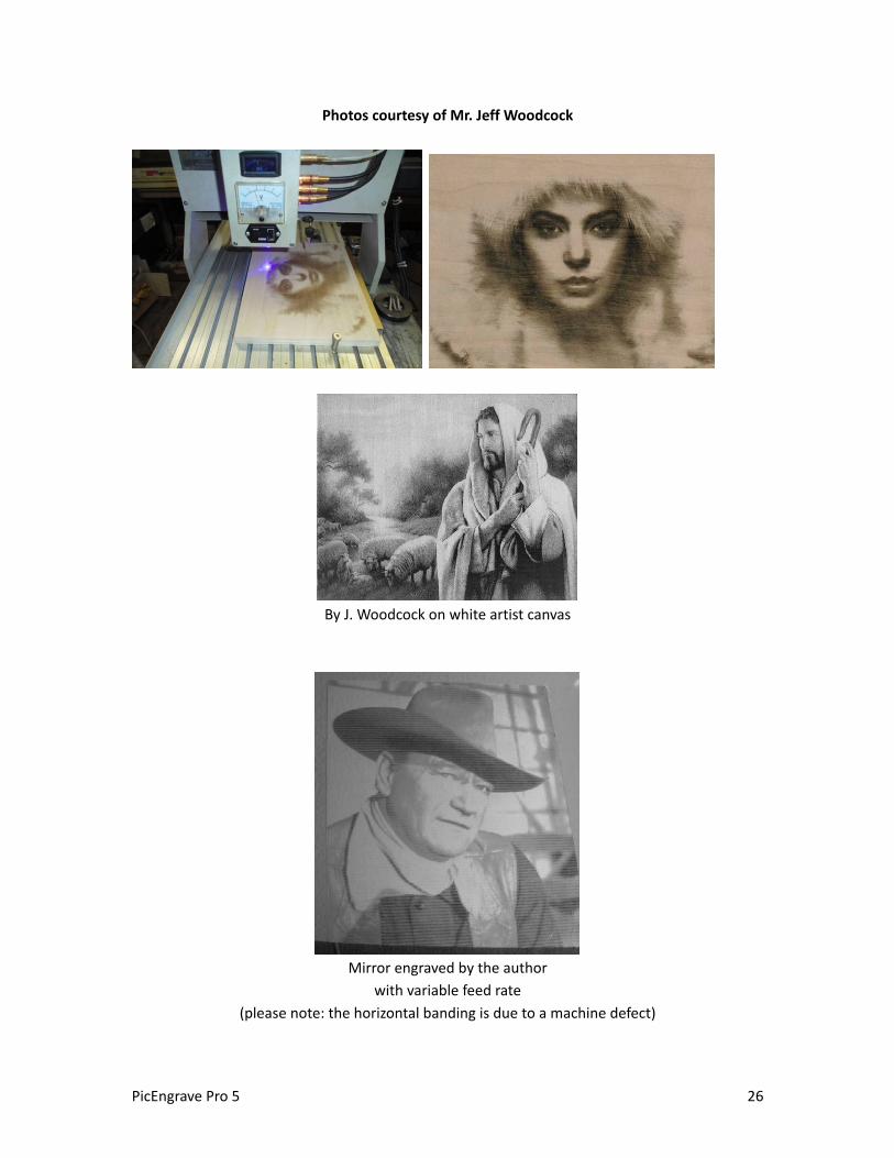
Photos courtesy of Mr. Jeff Woodcock
By J. Woodcock on white artist canvas
Mirror engraved by the author
with variable feed rate
(please note: the horizontal banding is due to a machine defect)
PicEngrave Pro 5 26
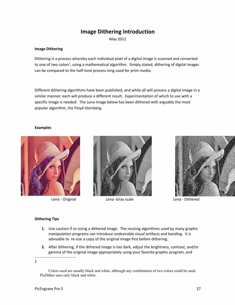
Image Dithering IntroductionMay 2012
Image Dithering
Dithering is a process whereby each individual pixel of a digital image is scanned and converted
to one of two colors1, using a mathematical algorithm. Simply stated, dithering of digital images
can be compared to the half-tone process long used for print media.
Different dithering algorithms have been published, and while all will process a digital image in a
similar manner, each will produce a different result. Experimentation of which to use with a
specific image is needed. The Lena image below has been dithered with arguably the most
popular algorithm, the Floyd-Steinberg.
Examples
Lena - Original Lena -Gray scale Lena - Dithered
Dithering Tips
1. Use caution if re-sizing a dithered image. The resizing algorithms used by many graphic manipulation programs can introduce undesirable visual artifacts and banding. It is advisable to re-size a copy of the original image first before dithering.
2. After dithering, if the dithered image is too dark, adjust the brightness, contrast, and/or gamma of the original image appropriately using your favorite graphic program, and
1
Colors used are usually black and white, although any combination of two colors could be used. PicDither uses only black and white.
PicEngrave Pro 5 27

process with PicDither again.
3. For best view of your dithered images, proof print them at 100% scale using an ink jet printer. Most laser printers and video monitors will not display an accurate representation of dithered images.
4. To avoid compression artifacts, dithered images can be saved only as an uncompressed BMP file composed of black and white pixels only.
5. Dithering time will be greater for larger images.
Dithering Examples
Gray scale Threshold Floyd-Steinberg False Floyd-Steinberg
Burkes Jarvis, Judice and Ninke Stuki Sierra
Two-row Sierra Sierra Lite Atkinson Random
As the name implies, the Random dither should not repeat a pattern.
PicEngrave Pro 5 28


