OR FORM WITHOUT THE WRITTEN APPROVAL OF GRIZZLY INDUSTRIAL, INC.#KB18583 PRINTED IN CHINA V1.05.17
This manual provides critical safety instructions on the proper setup, operation, maintenance, and service of this machine/tool. Save this document, refer to it often, and use it to instruct other operators.
Failure to read, understand and follow the instructions in this manual may result in fire or serious personal injury—including amputation, electrocution, or death.
The owner of this machine/tool is solely responsible for its safe use. This responsibility includes but is not limited to proper installation in a safe environment, personnel training and usage authorization, proper inspection and maintenance, manual availability and compre-hension, application of safety devices, cutting/sanding/grinding tool integrity, and the usage of personal protective equipment.
The manufacturer will not be held liable for injury or property damage from negligence, improper training, machine modifications or misuse.
Some dust created by power sanding, sawing, grinding, drilling, and other construction activities contains chemicals known to the State of California to cause cancer, birth defects or other reproductive harm. Some examples of these chemicals are:
• Lead from lead-based paints.• Crystalline silica from bricks, cement and other masonry products.• Arsenic and chromium from chemically-treated lumber.
Your risk from these exposures varies, depending on how often you do this type of work. To reduce your exposure to these chemicals: Work in a well ventilated area, and work with approved safety equip-ment, such as those dust masks that are specially designed to filter out microscopic particles.
Table of ContentsINTRODUCTION ............................................................................................................................... 2
Machine Description ................................................................................................................... 2Contact Info ................................................................................................................................ 2Manual Accuracy ........................................................................................................................ 2Identification ............................................................................................................................... 3Controls & Components ............................................................................................................. 4Machine Data Sheet ................................................................................................................... 5
SECTION 1: SAFETY ....................................................................................................................... 7Safety Instructions for Machinery ............................................................................................... 7Additional Safety for Metal Shears ............................................................................................. 9
SECTION 6: SERVICE ................................................................................................................... 23Troubleshooting ........................................................................................................................ 23Adjusting Blade Gap ................................................................................................................ 24Replacing Blades ..................................................................................................................... 25Adjusting Gibs .......................................................................................................................... 27
SECTION 7: PARTS ....................................................................................................................... 28G0828 Parts ............................................................................................................................. 28G0829 Parts ............................................................................................................................. 29Labels & Cosmetics ................................................................................................................. 30
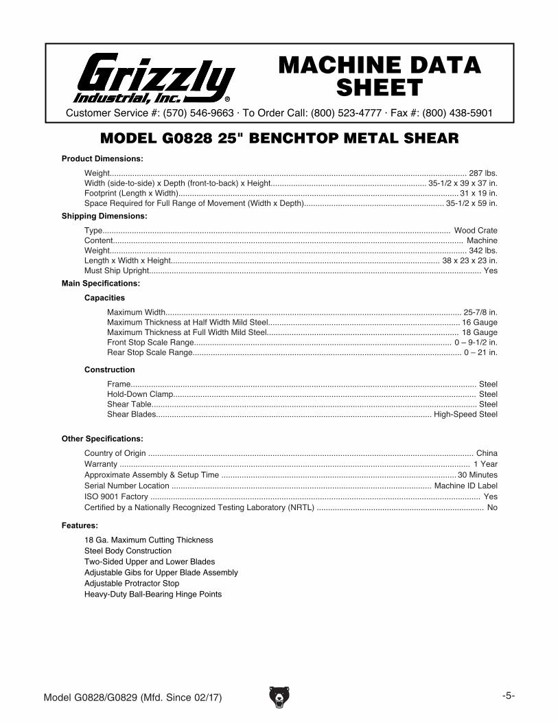
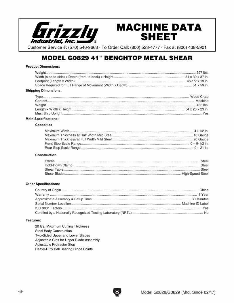
The main difference between the G0828 and G0829 is the size of the bed and cutting capac-ity. The G0828 can cut an 18-gauge sheet at a maximum width of 257⁄8". The G0829 can cut a 20-gauge sheet at a maximum width of 411⁄2".
Machine Description
We are proud to provide a high-quality owner’s manual with your new machine!
We made every effort to be exact with the instruc-tions, specifications, drawings, and photographs in this manual. Sometimes we make mistakes, but our policy of continuous improvement also means that sometimes the machine you receive is slightly different than shown in the manual.
If you find this to be the case, and the difference between the manual and machine leaves you confused or unsure about something, check our website for an updated version. We post current manuals and manual updates for free on our web-site at www.grizzly.com.
Alternatively, you can call our Technical Support for help. Before calling, make sure you write down the Manufacture Date and Serial Number from the machine ID label (see below). This information is required for us to provide proper tech support, and it helps us determine if updated documenta-tion is available for your machine.
Manufacture Date
Serial Number
Manual Accuracy
We stand behind our machines! If you have ques-tions or need help, contact us with the information below. Before contacting, make sure you get the serial number and manufacture date from the machine ID label. This will help us help you faster.
To reduce your risk of serious injury, read this entire manual BEFORE using machine.
BladeGuard
Work StopSupport Rod
Adjustable Angle Guide
Work StopAdjustment Assembly
Upper Blade Base
Cam Shaft Lever
Hold-Down BarBed
Blade (Upper)
Blade (Lower)
Rear Work Stop
Rear View (G0828 Shown)
Cutting Lever
90° Guide
-4- Model G0828/G0829 (Mfd. Since 02/17)
Controls & Components
Use Figures 1-2 and the descriptions below to become familiar with the basic controls of the G0828 and G0829 metal shears. The controls on both models function identically.
Adjustable Angle Guide: Adjusts from 0° to 180° for making angled cuts.
Upper Blade: Moves with the cutting lever to shear the workpiece against the lower blade for cutting operations. The upper and lower blades are interchangeable and reversible.
Cutting Lever: Controls movement of the upper blade for cutting.
Hold-Down Bar: Spring-loaded bar holds the workpiece in position during cutting operation as cutting lever is pulled down.
90° Guide: Helps the operator square the workpiece with the blades.
Figure 1. Basic controls (front).
Upper Blade
Hold-Down Bar
Work Stop Adjustment Assembly: Moves the rear work stop in or out at a specific distance from the lower blade. Allows the operator to set up the shear for multiple cuts of the same length.
Lower Blade: Fixed on frame. The upper and lower blades are interchangeable and reversible. Rear Work Stop: Used for making repetitive cuts.
Support Rods: Provide a measurement refer-ence from the blade to the work stops. Support the adjustable work stop assemblies and rear work stop.
Figure 2. Basic controls (rear).
RearWork Stop
Lower Blade
Work Stop Adjustment Assembly
Support RodsCutting Lever
Adjustable Angle Guide
90° Guide
Model G0828/G0829 (Mfd. Since 02/17) -5-
The information contained herein is deemed accurate as of 11/3/2016 and represents our most recent product specifications.Due to our ongoing improvement efforts, this information may not accurately describe items previously purchased. PAGE 1 OF 1Model G0828
MACHINE DATASHEET
Customer Service #: (570) 546-9663 · To Order Call: (800) 523-4777 · Fax #: (800) 438-5901
MODEL G0828 25" BENCHTOP METAL SHEARProduct Dimensions:
Weight.............................................................................................................................................................. 287 lbs.Width (side-to-side) x Depth (front-to-back) x Height..................................................................... 35-1/2 x 39 x 37 in.Footprint (Length x Width)............................................................................................................................ 31 x 19 in.Space Required for Full Range of Movement (Width x Depth).............................................................. 35-1/2 x 59 in.
Shipping Dimensions:
Type.......................................................................................................................................................... Wood CrateContent........................................................................................................................................................... MachineWeight.............................................................................................................................................................. 342 lbs.Length x Width x Height....................................................................................................................... 38 x 23 x 23 in.Must Ship Upright................................................................................................................................................... Yes
Main Specifications:
Capacities
Maximum Width................................................................................................................................... 25-7/8 in.Maximum Thickness at Half Width Mild Steel..................................................................................... 16 GaugeMaximum Thickness at Full Width Mild Steel..................................................................................... 18 GaugeFront Stop Scale Range.................................................................................................................. 0 – 9-1/2 in.Rear Stop Scale Range....................................................................................................................... 0 – 21 in.
Country of Origin ................................................................................................................................................ ChinaWarranty ........................................................................................................................................................... 1 YearApproximate Assembly & Setup Time ........................................................................................................ 30 MinutesSerial Number Location ................................................................................................................... Machine ID LabelISO 9001 Factory .................................................................................................................................................. YesCertified by a Nationally Recognized Testing Laboratory (NRTL) .......................................................................... No
Features:
18 Ga. Maximum Cutting ThicknessSteel Body ConstructionTwo-Sided Upper and Lower BladesAdjustable Gibs for Upper Blade AssemblyAdjustable Protractor StopHeavy-Duty Ball-Bearing Hinge Points
Machine Data Sheet
-6- Model G0828/G0829 (Mfd. Since 02/17)
The information contained herein is deemed accurate as of 11/3/2016 and represents our most recent product specifications.Due to our ongoing improvement efforts, this information may not accurately describe items previously purchased. PAGE 1 OF 1Model G0829
MACHINE DATASHEET
Customer Service #: (570) 546-9663 · To Order Call: (800) 523-4777 · Fax #: (800) 438-5901
MODEL G0829 41" BENCHTOP METAL SHEARProduct Dimensions:
Weight.............................................................................................................................................................. 397 lbs.Width (side-to-side) x Depth (front-to-back) x Height........................................................................... 51 x 39 x 37 in.Footprint (Length x Width)..................................................................................................................... 46-1/2 x 19 in.Space Required for Full Range of Movement (Width x Depth).................................................................... 51 x 59 in.
Shipping Dimensions:
Type.......................................................................................................................................................... Wood CrateContent........................................................................................................................................................... MachineWeight.............................................................................................................................................................. 463 lbs.Length x Width x Height....................................................................................................................... 54 x 23 x 23 in.Must Ship Upright................................................................................................................................................... Yes
Main Specifications:
Capacities
Maximum Width................................................................................................................................... 41-1/2 in.Maximum Thickness at Half Width Mild Steel..................................................................................... 18 GaugeMaximum Thickness at Full Width Mild Steel..................................................................................... 20 GaugeFront Stop Scale Range.................................................................................................................. 0 – 9-1/2 in.Rear Stop Scale Range....................................................................................................................... 0 – 21 in.
Country of Origin ................................................................................................................................................ ChinaWarranty ........................................................................................................................................................... 1 YearApproximate Assembly & Setup Time ........................................................................................................ 30 MinutesSerial Number Location ................................................................................................................... Machine ID LabelISO 9001 Factory .................................................................................................................................................. YesCertified by a Nationally Recognized Testing Laboratory (NRTL) .......................................................................... No
Features:
20 Ga. Maximum Cutting ThicknessSteel Body ConstructionTwo-Sided Upper and Lower BladesAdjustable Gibs for Upper Blade AssemblyAdjustable Protractor StopHeavy-Duty Ball Bearing Hinge Points
Model G0828/G0829 (Mfd. Since 02/17) -7-
ELECTRICAL EQUIPMENT INJURY RISKS. You can be shocked, burned, or killed by touching live electrical components or improperly grounded machinery. To reduce this risk, only allow qualified service personnel to do electrical installation or repair work, and always disconnect power before accessing or exposing electrical equipment.
DISCONNECT POWER FIRST. Always discon-nect machine from power supply BEFORE making adjustments, changing tooling, or servicing machine. This prevents an injury risk from unintended startup or contact with live electrical components.
EYE PROTECTION. Always wear ANSI-approved safety glasses or a face shield when operating or observing machinery to reduce the risk of eye injury or blindness from flying particles. Everyday eyeglasses are NOT approved safety glasses.
OWNER’S MANUAL. Read and understand this owner’s manual BEFORE using machine.
TRAINED OPERATORS ONLY. Untrained oper-ators have a higher risk of being hurt or killed. Only allow trained/supervised people to use this machine. When machine is not being used, dis-connect power, remove switch keys, or lock-out machine to prevent unauthorized use—especially around children. Make your workshop kid proof!
DANGEROUS ENVIRONMENTS. Do not use machinery in areas that are wet, cluttered, or have poor lighting. Operating machinery in these areas greatly increases the risk of accidents and injury.
MENTAL ALERTNESS REQUIRED. Full mental alertness is required for safe operation of machin-ery. Never operate under the influence of drugs or alcohol, when tired, or when distracted.
For Your Own Safety, Read Instruction Manual Before Operating This Machine
The purpose of safety symbols is to attract your attention to possible hazardous conditions. This manual uses a series of symbols and signal words intended to convey the level of impor-tance of the safety messages. The progression of symbols is described below. Remember that safety messages by themselves do not eliminate danger and are not a substitute for proper accident prevention measures. Always use common sense and good judgment.
Indicates a potentially hazardous situation which, if not avoided, MAY result in minor or moderate injury. It may also be used to alert against unsafe practices.
Indicates a potentially hazardous situation which, if not avoided, COULD result in death or serious injury.
Indicates an imminently hazardous situation which, if not avoided, WILL result in death or serious injury.
This symbol is used to alert the user to useful information about proper operation of the machine.NOTICE
Safety Instructions for Machinery
SECTION 1: SAFETY
-8- Model G0828/G0829 (Mfd. Since 02/17)
WEARING PROPER APPAREL. Do not wear clothing, apparel or jewelry that can become entangled in moving parts. Always tie back or cover long hair. Wear non-slip footwear to reduce risk of slipping and losing control or accidentally contacting cutting tool or moving parts.
HAZARDOUS DUST. Dust created by machinery operations may cause cancer, birth defects, or long-term respiratory damage. Be aware of dust hazards associated with each workpiece mate-rial. Always wear a NIOSH-approved respirator to reduce your risk.
HEARING PROTECTION. Always wear hear-ing protection when operating or observing loud machinery. Extended exposure to this noise without hearing protection can cause permanent hearing loss.
REMOVE ADJUSTING TOOLS. Tools left on machinery can become dangerous projectiles upon startup. Never leave chuck keys, wrenches, or any other tools on machine. Always verify removal before starting!
USE CORRECT TOOL FOR THE JOB. Only use this tool for its intended purpose—do not force it or an attachment to do a job for which it was not designed. Never make unapproved modifica-tions—modifying tool or using it differently than intended may result in malfunction or mechanical failure that can lead to personal injury or death!
AWKWARD POSITIONS. Keep proper footing and balance at all times when operating machine. Do not overreach! Avoid awkward hand positions that make workpiece control difficult or increase the risk of accidental injury.
CHILDREN & BYSTANDERS. Keep children and bystanders at a safe distance from the work area.Stop using machine if they become a distraction.
GUARDS & COVERS. Guards and covers reduce accidental contact with moving parts or flying debris. Make sure they are properly installed, undamaged, and working correctly BEFORE operating machine.
FORCING MACHINERY. Do not force machine. It will do the job safer and better at the rate for which it was designed.
NEVER STAND ON MACHINE. Serious injury may occur if machine is tipped or if the cutting tool is unintentionally contacted.
STABLE MACHINE. Unexpected movement dur-ing operation greatly increases risk of injury or loss of control. Before starting, verify machine is stable and mobile base (if used) is locked.
USE RECOMMENDED ACCESSORIES. Consult this owner’s manual or the manufacturer for rec-ommended accessories. Using improper acces-sories will increase the risk of serious injury.
UNATTENDED OPERATION. To reduce the risk of accidental injury, turn machine OFF and ensure all moving parts completely stop before walking away. Never leave machine running while unattended.
MAINTAIN WITH CARE. Follow all maintenance instructions and lubrication schedules to keep machine in good working condition. A machine that is improperly maintained could malfunction, leading to serious personal injury or death.
DAMAGED PARTS. Regularly inspect machine for damaged, loose, or mis-adjusted parts—or any condition that could affect safe operation. Immediately repair/replace BEFORE operating machine. For your own safety, DO NOT operate machine with damaged parts!
MAINTAIN POWER CORDS. When disconnect-ing cord-connected machines from power, grab and pull the plug—NOT the cord. Pulling the cord may damage the wires inside. Do not handle cord/plug with wet hands. Avoid cord damage by keeping it away from heated surfaces, high traffic areas, harsh chemicals, and wet/damp locations.
EXPERIENCING DIFFICULTIES. If at any time you experience difficulties performing the intend-ed operation, stop using the machine! Contact our Technical Support at (570) 546-9663.
Model G0828/G0829 (Mfd. Since 02/17) -9-
Additional Safety for Metal Shears
AMPUTATION HAZARD. The shear blades can easily pinch, crush, or amputate fingers or other body parts. Always keep hands, fingers, and other body parts away from the blades during operation.
SHARP METAL EDGES. Sharp edges on newly cut sheet metal workpieces can easily cause deep cuts while handling. Wear leather gloves to help protect your hands when handling workpieces, and always chamfer and debur sharp workpiece edges.
PROPER WORKPIECE MATERIAL. This shear is only intended for cutting ferrous and non-ferrous sheet metal or flat stock. Do not attempt to cut round metal stock, glass, wood, drywall, backer board, plywood, or other material not intended for this machine. Cutting incorrect materials can pro-duce unexpected results, which increases the risk of injury, and may result in damage to the machine.
SECURE SHEAR BEFORE USE. Before using, fasten shear to a sturdy surface that can withstand the dynamic forces involved in shearing sheet metal. Otherwise, shear may unexpectedly move or fall, causing serious injury or property damage.
STABLE FOOTING. This shear requires you to apply a moderate/high level force while cutting. Without stable footing, you could slip or fall, which could cause personal injury. Always stand with both feet comfortably on a non-slip surface during operation.
BODY POSITION. The forces and body motion required to operate this shear can result in opera-tor injury over time if proper technique is not used. Always keep your body centered with the machine and your back straight when applying pressure against handles.
BLADE CONDITION. Blades that are sharp, undamaged, and properly adjusted will reduce risk of injury and improve cutting results. Always keep blades properly maintained.
BLADE GUARD. The blade guard is designed to reduce risk of amputation. Always keep guard properly attached and in good condition during operation.
RATED CAPACITY. Only use sheet metal that is within the rated capacity of this shear (refer to the Machine Data Sheets on Page 5 and 6).
Like all machinery there is potential danger when operating this machine. Accidents are frequently caused by lack of familiarity or failure to pay attention. Use this machine with respect and caution to decrease the risk of operator injury. If normal safety pre-cautions are overlooked or ignored, seri-ous personal injury may occur.
No list of safety guidelines can be com-plete. Every shop environment is different. Always consider safety first, as it applies to your individual working conditions. Use this and other machinery with caution and respect. Failure to do so could result in serious personal injury, damage to equip-ment, or poor work results.
-10- Model G0828/G0829 (Mfd. Since 02/17)
SECTION 2: SETUP
This machine was carefully packaged for safe transport. When unpacking, separate all enclosed items from packaging materials and inspect them for shipping damage. If items are damaged, please call us immediately at (570) 546-9663.
IMPORTANT: Save all packaging materials until you are completely satisfied with the machine and have resolved any issues between Grizzly or the shipping agent. You MUST have the original pack-aging to file a freight claim. It is also extremely helpful if you need to return your machine later.
Unpacking
SUFFOCATION HAZARD!Keep children and pets away from plastic bags or packing materials shipped with this machine. Discard immediately.
The following are needed to complete the setup process, but are not included with your machine.
Description Qty• Additional People ....................... As Needed• Safety Glasses ................ 1 for Each Person• Cleaner/Degreaser (Page 11) ..... As Needed• Disposable Shop Rags ............... As Needed• Hex Wrench 4mm, 5mm, 6mm .........1 Each• Open-End Wrench 14mm ........................... 2• Mounting Hardware (Page 13) ... As Needed• Forklift ......................................................... 1• Lifting Straps (rated for 500 lbs.) ................ 2
Needed for Setup
Inventory
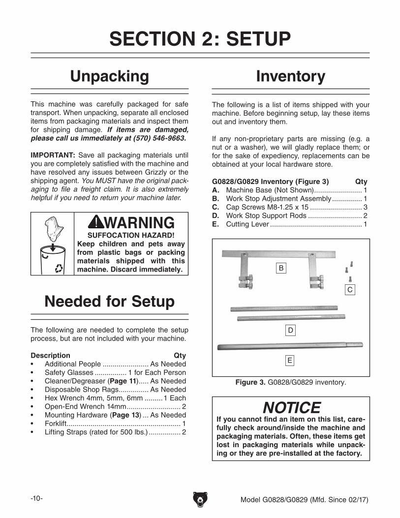
The following is a list of items shipped with your machine. Before beginning setup, lay these items out and inventory them.
If any non-proprietary parts are missing (e.g. a nut or a washer), we will gladly replace them; or for the sake of expediency, replacements can be obtained at your local hardware store.
G0828/G0829 Inventory (Figure 3) QtyA. Machine Base (Not Shown) ........................ 1B. Work Stop Adjustment Assembly ............... 1C. Cap Screws M8-1.25 x 15 .......................... 3D. Work Stop Support Rods ........................... 2E. Cutting Lever .............................................. 1
NOTICEIf you cannot find an item on this list, care-fully check around/inside the machine and packaging materials. Often, these items get lost in packaging materials while unpack-ing or they are pre-installed at the factory.
Figure 3. G0828/G0829 inventory.
B
C
D
E
Model G0828/G0829 (Mfd. Since 02/17) -11-
The unpainted surfaces of your machine are coated with a heavy-duty rust preventative that prevents corrosion during shipment and storage. This rust preventative works extremely well, but it will take a little time to clean.
Be patient and do a thorough job cleaning your machine. The time you spend doing this now will give you a better appreciation for the proper care of your machine's unpainted surfaces.
There are many ways to remove this rust preven-tative, but the following steps work well in a wide variety of situations. Always follow the manufac-turer’s instructions with any cleaning product you use and make sure you work in a well-ventilated area to minimize exposure to toxic fumes.
Before cleaning, gather the following:• Disposable rags• Cleaner/degreaser (WD•40 works well)• Safety glasses & disposable gloves• Plastic paint scraper (optional)
Basic steps for removing rust preventative:
1. Put on safety glasses.
2. Coat the rust preventative with a liberal amount of cleaner/degreaser, then let it soak for 5–10 minutes.
3. Wipe off the surfaces. If your cleaner/degreas-er is effective, the rust preventative will wipe off easily. If you have a plastic paint scraper, scrape off as much as you can first, then wipe off the rest with the rag.
4. Repeat Steps 2–3 as necessary until clean, then coat all unpainted surfaces with a quality metal protectant to prevent rust.
Gasoline and petroleum products have low flash points and can explode or cause fire if used to clean machinery. Avoid using these products to clean machinery.
Many cleaning solvents are toxic if inhaled. Only work in a well-ventilated area.
NOTICEAvoid chlorine-based solvents, such as acetone or brake parts cleaner, that may damage painted surfaces.
Cleanup
T23692—Orange Power DegreaserA great product for removing the waxy shipping grease from your machine during clean up.
Figure 4. T23692 Orange Power Degreaser.
-12- Model G0828/G0829 (Mfd. Since 02/17)
Site Considerations
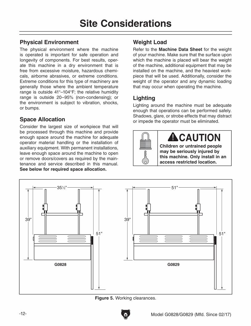
Figure 5. Working clearances.
51"
51"
351⁄2"
G0828 G0829
39"39"
51"
Weight LoadRefer to the Machine Data Sheet for the weight of your machine. Make sure that the surface upon which the machine is placed will bear the weight of the machine, additional equipment that may be installed on the machine, and the heaviest work-piece that will be used. Additionally, consider the weight of the operator and any dynamic loading that may occur when operating the machine.
Physical EnvironmentThe physical environment where the machine is operated is important for safe operation and longevity of components. For best results, oper-ate this machine in a dry environment that is free from excessive moisture, hazardous chemi-cals, airborne abrasives, or extreme conditions. Extreme conditions for this type of machinery are generally those where the ambient temperature range is outside 41°–104°F; the relative humidity range is outside 20–95% (non-condensing); or the environment is subject to vibration, shocks, or bumps.
Children or untrained people may be seriously injured by this machine. Only install in an access restricted location.
LightingLighting around the machine must be adequate enough that operations can be performed safely. Shadows, glare, or strobe effects that may distract or impede the operator must be eliminated.Space Allocation
Consider the largest size of workpiece that will be processed through this machine and provide enough space around the machine for adequate operator material handling or the installation of auxiliary equipment. With permanent installations, leave enough space around the machine to open or remove doors/covers as required by the main-tenance and service described in this manual. See below for required space allocation.
Model G0828/G0829 (Mfd. Since 02/17) -13-
Lifting & Placing
HEAVY LIFT!Straining or crushing injury may occur from improperly lifting machine or some of its parts. To reduce this risk, get help from other people and use a forklift (or other lifting equipment) rated for weight of this machine.
To lift and place shear on workbench:
1. Move shear to installation location while it is still on shipping pallet.
2. To avoid damage from lifting straps, remove M6-1 x 12 cap screws and 6mm flat washers (14 on G0828, 16 on G0829) securing lower cover, blade guard, and upper cover, (see Figure 6).
7. Fasten shear to workbench as recommended in Bench Mounting.
3. Remove fasteners securing shear to pallet. Save hardware for mounting in Step 7.
4. Position straps under shear and attach to forklift. Or, with help from others, lift shear onto workbench and proceed to Step 6.
Bench Mounting
The base of this machine has mounting holes that allow it to be fastened to a workbench or other mounting surface to prevent it from moving during operation and causing accidental injury or damage.
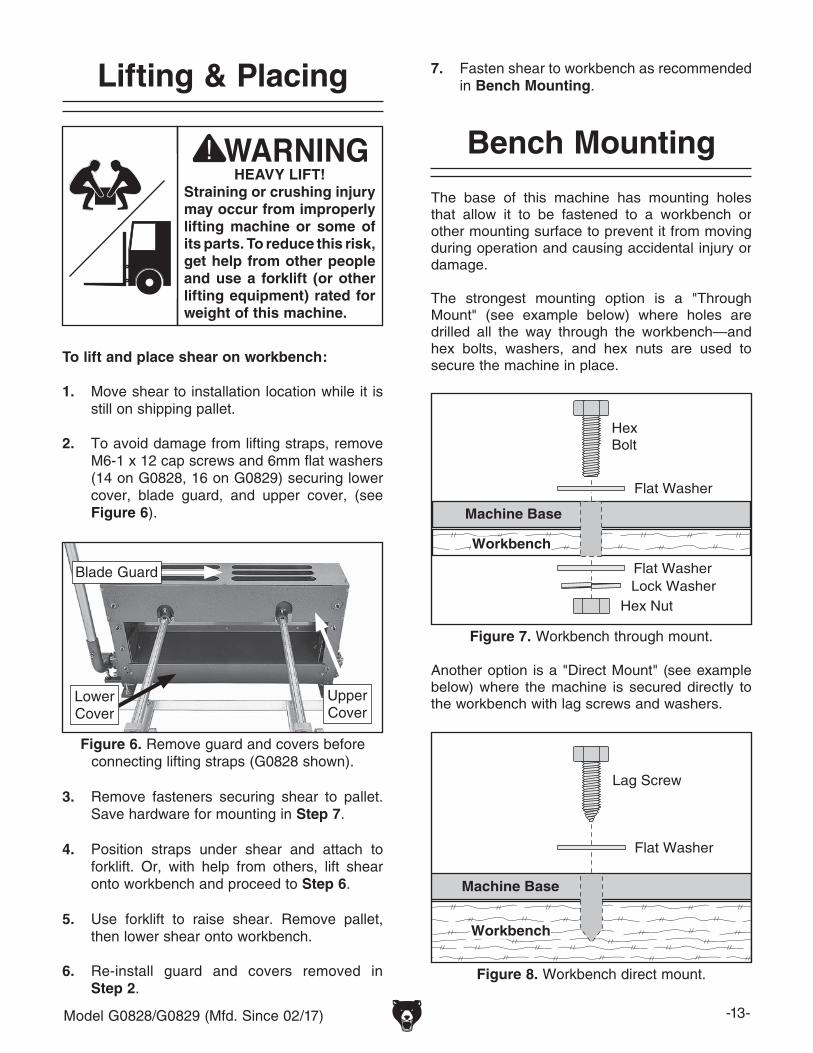
The strongest mounting option is a "Through Mount" (see example below) where holes are drilled all the way through the workbench—and hex bolts, washers, and hex nuts are used to secure the machine in place.
Machine Base
Workbench
HexBolt
Flat Washer
Flat Washer Lock Washer
Hex Nut
Machine Base
Workbench
Lag Screw
Flat Washer
Another option is a "Direct Mount" (see example below) where the machine is secured directly to the workbench with lag screws and washers.
Figure 7. Workbench through mount.
Figure 8. Workbench direct mount.
5. Use forklift to raise shear. Remove pallet, then lower shear onto workbench.
6. Re-install guard and covers removed in Step 2.
Figure 6. Remove guard and covers before connecting lifting straps (G0828 shown).
Blade Guard
Lower Cover
Upper Cover
-14- Model G0828/G0829 (Mfd. Since 02/17)
Leveling
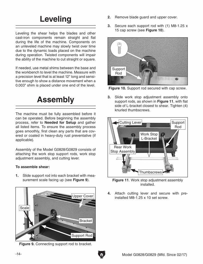
Leveling the shear helps the blades and other cast-iron components remain straight and flat during the life of the machine. Components on an unleveled machine may slowly twist over time due to the dynamic loads placed on the machine during operation. Twisted components will impair the ability of the machine to cut straight or square.
If needed, use metal shims between the base and the workbench to level the machine. Measure with a precision level that is at least 12" long and sensi-tive enough to show a distance movement when a 0.003" shim is placed under one end of the level.
3. Slide work stop adjustment assembly onto support rods, as shown in Figure 11, with flat side of L-bracket closest to shear. Tighten (4) knurled thumbscrews.
Assembly
Assembly of the Model G0828/G0829 consists of attaching the work stop support rods, work stop adjustment assembly, and cutting lever.
To assemble shear:
1. Slide support rod into each bracket with mea-surement scale facing up (see Figure 9).
4. Attach cutting lever and secure with pre-installed M8-1.25 x 10 set screw.
Figure 11. Work stop adjustment assembly installed.
Support Rod
Rear Work Stop Assembly
Thumbscrews
2. Remove blade guard and upper cover.
3. Secure each support rod with (1) M8-1.25 x 15 cap screw (see Figure 10).
Figure 10. Support rod secured with cap screw.
Support Rod
The machine must be fully assembled before it can be operated. Before beginning the assembly process, refer to Needed for Setup and gather all listed items. To ensure the assembly process goes smoothly, first clean any parts that are cov-ered or coated in heavy-duty rust preventative (if applicable).
Figure 9. Connecting support rod to bracket.
Bracket
Support Rod
Scale
Upper Cover
Cutting Lever
Work StopL-Bracket
Model G0828/G0829 (Mfd. Since 02/17) -15-
SECTION 3: OPERATIONS
Operation Overview
The purpose of this overview is to provide the nov-ice machine operator with a basic understanding of how the machine is used during operation, so the machine controls/components discussed later in this manual are easier to understand.
Due to the generic nature of this overview, it is not intended to be an instructional guide. To learn more about specific operations, read this entire manual, seek additional training from experienced machine operators, and do additional research outside of this manual by reading "how-to" books, trade magazines, or websites.
To complete a typical operation, the operator does the following:
1. Examines workpiece to make sure it is suit-able for cutting.
2. Adjusts rear work stop for length of cut.
3. Puts on safety glasses, leather boots, and leather gloves.
4. Places workpiece on bed and up against side work stop.
5. Slides workpiece under blades and against rear work stop.
6. Using good body position, firmly pulls down on cutting lever to make cut.
7. Lifts cutting lever and removes workpiece or repeats Steps 5–6 to make additional cuts.
To reduce your risk of serious injury, read this entire manual BEFORE using machine.
If you are not experienced with this type of machine, WE STRONGLY RECOMMEND that you seek additional training outside of this manual. Read books/magazines or get formal training before beginning any proj-ects. Regardless of the content in this sec-tion, Grizzly Industrial will not be held liable for accidents caused by lack of training.
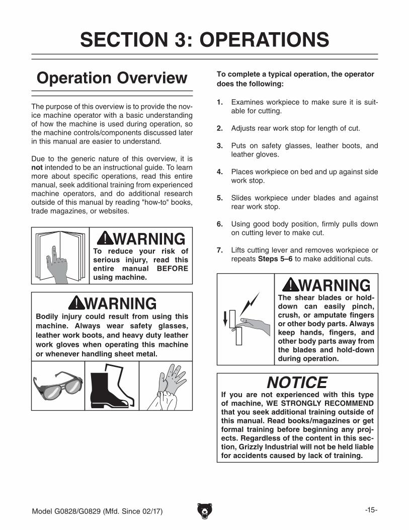
Bodily injury could result from using this machine. Always wear safety glasses, leather work boots, and heavy duty leather work gloves when operating this machine or whenever handling sheet metal.
The shear blades or hold-down can easily pinch, crush, or amputate fingers or other body parts. Always keep hands, fingers, and other body parts away from the blades and hold-down during operation.
-16- Model G0828/G0829 (Mfd. Since 02/17)
Cutting Tips
• Keep the upper blade properly adjusted to the lower blade (refer to Adjusting Blade Gap on Page 24 for detailed instructions). This will help ensure good cutting results and avoid blade damage.
• Before each operation, clear cut-offs or debris away from the shear.
• Make sure the 90° guide is square with the blades (see Page 18). This will help ensure the cut is square.
• Use the cutting lever to engage the hold-down bar with the workpiece, then check the workpiece position. If it is correct, continue lowering the cutting lever to complete the cut.
• The shearing action of the blades works simi-larly to a pair of scissors (see the illustration in Figure 12). Use even pressure on the cut-ting lever to produce good results.
Shearing Action
Upper Blade
Lower Blade
Figure 12. Blade shearing action.
Adjusting Hold-Down Bar
The hold-down bar secures the workpiece to the bed before the blades shear the workpiece.
The hold-down bar is adjustable for height. The G0828 uses two adjustment hex bolts and hex nuts (see Figure 13). The G0829 uses three adjustment hex bolts and hex nuts.
Figure 13. Hold-down bar adjustment (G0828 shown).
Hold-Down Bar
Adjustment Hex Bolt
Hex Nut
Bed
Model G0828/G0829 (Mfd. Since 02/17) -17-
Adjusting Rear Work Stop
The rear work stop is used for making repetitive cuts. The adjustable assemblies allow for precise positioning of the work stop.
To position rear work stop:
1. Slide work stop adjustment assembly evenly along support rods so rear work stop leading edge is at approximate desired distance from cutting edges of blades (see Figure 15).
Note: Move work stop assembly evenly on both sides to keep it parallel with blades. Use scales on top of support rods for approximate positioning. Use fine ruler or tape measure for precise positioning.
2. To keep rear work stop assemblies secured in desired position, tighten knurled thumb-screws (see Figure 15).
To adjust rear work stop assembly position:
1. Measure distance between cutting edge of bed and leading edge of work stop. Compare to scale measurement on each support rod.
2. If measurement does not match scale, loosen cap screws securing support rods and adjust each one until measurements match.
3. Re-tighten cap screws to secure support rods.
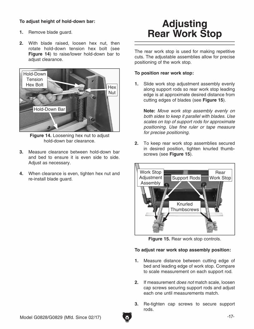
2. With blade raised, loosen hex nut, then rotate hold-down tension hex bolt (see Figure 14) to raise/lower hold-down bar to adjust clearance.
To adjust height of hold-down bar:
1. Remove blade guard.
3. Measure clearance between hold-down bar and bed to ensure it is even side to side. Adjust as necessary.
4. When clearance is even, tighten hex nut and re-install blade guard.
Figure 14. Loosening hex nut to adjust hold-down bar clearance.
Hold-Down Bar
Hold-Down Tension Hex Bolt Hex
Nut
Figure 15. Rear work stop controls.
Support Rods
Knurled Thumbscrews
Work Stop Adjustment Assembly
RearWork Stop
-18- Model G0828/G0829 (Mfd. Since 02/17)
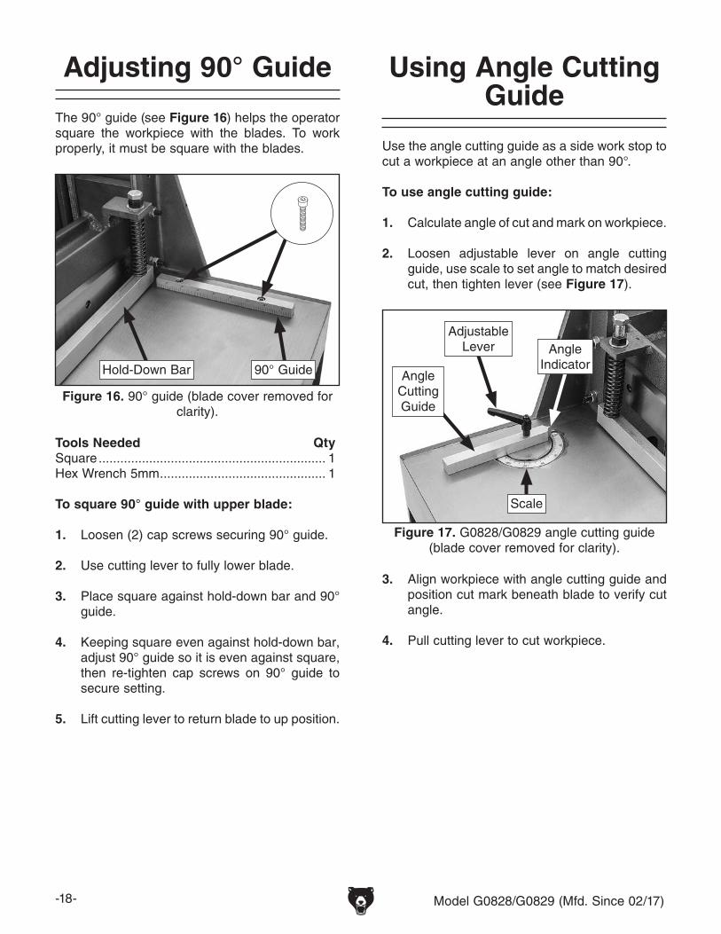
Using Angle Cutting Guide
Use the angle cutting guide as a side work stop to cut a workpiece at an angle other than 90°.
To use angle cutting guide:
1. Calculate angle of cut and mark on workpiece.
2. Loosen adjustable lever on angle cutting guide, use scale to set angle to match desired cut, then tighten lever (see Figure 17).
3. Align workpiece with angle cutting guide and position cut mark beneath blade to verify cut angle.
4. Pull cutting lever to cut workpiece.
Adjusting 90° Guide
The 90° guide (see Figure 16) helps the operator square the workpiece with the blades. To work properly, it must be square with the blades.
3. Place square against hold-down bar and 90° guide.
4. Keeping square even against hold-down bar, adjust 90° guide so it is even against square, then re-tighten cap screws on 90° guide to secure setting.
5. Lift cutting lever to return blade to up position.
Figure 16. 90° guide (blade cover removed for clarity).
Installing unapproved accessories may cause machine to malfunction, resulting in serious personal injury or machine damage. To reduce this risk, only install accessories recommended for this machine by Grizzly.
NOTICERefer to our website or latest catalog for additional recommended accessories.
T25208—23-Pc. Deburring SetIncludes: 380-0060 double burr; 2-piece 380-0088 handle; 380-0097, 380-0098, and 380-0091 holders; D25 and D40 scrapers; C20 countersink; ES100 and ES200 blades (5 each); V13, and A13 blades; wrench and hex wrenches; and case.
Figure 18. Model T25208 Deburring Set.
H5614—Sheet Metal Gauge US StandardCalibrated for sheet metal sized from 0- to 30-gauge. The front is marked with gauge sizes, the back is marked with actual inch measurements.
Figure 19. H5614 Sheet Metal Gauge.
Recommended Metal ProtectantsG5562—SLIPIT® 1 Qt. GelG5563—SLIPIT® 12 oz SprayG2871—Boeshield® T-9 12 oz SprayG2870—Boeshield® T-9 4 oz SprayH3788—G96® Gun Treatment 12 oz SprayH3789—G96® Gun Treatment 4.5 oz Spray
Figure 20. Recommended products for protect-ing unpainted cast-iron/steel parts on machinery.
order online at www.grizzly.com or call 1-800-523-4777
-20- Model G0828/G0829 (Mfd. Since 02/17)
order online at www.grizzly.com or call 1-800-523-4777
T10456—Heavy-Duty Anti-Fatigue Mat 3' x 5'This heavy-duty anti-fatigue mat features beveled edges and no-slip tread for safety and comfort. Open-hole design allows liquid to drain through, so it's perfect for wet or oily conditions. Measures 3' wide x 5' long x 3/8" thick.
Figure 23. Model T10456 Anti-Fatigue Mat.
G8782—10" Aviation Tin Snips - 3 pc. SetPrecision, hardened-steel cutting jaws ensure that you’ll enjoy quality results each time you cut sheet metal. Color-coded to provide quick identi-fication, these snips feature thick grips for cutting comfort and a positive lock to prevent accidents. An efficient, economical alternative to high-priced, name-brand aviation snips.
Figure 24. Model G8782 10" Tin Snips.
T21318—36" Slip Roll, 22 GaugeSlip roll up to 36" wide and 22-gauge mild steel with this benchtop sheet metal roller. Cast-iron construction and 2" diameter ground and polished rolls make this slip roll ideal for many fabricat-ing uses. Features heavy bearings and gearing, precision-ground cast-iron rollers, and the ability to slip roll 3/16"-5/16" diameter rod/wire stock.
Figure 22. Model T21318 36" Slip Roll.
Model G0828/G0829 (Mfd. Since 02/17) -21-
order online at www.grizzly.com or call 1-800-523-4777
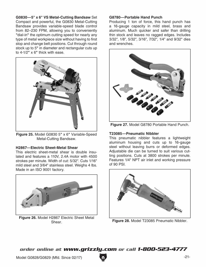
G0830—5" x 6" VS Metal-Cutting Bandsaw Set Compact and powerful, the G0830 Metal-Cutting Bandsaw provides variable-speed blade control from 82–230 FPM, allowing you to conveniently "dial-in" the optimum cutting speed for nearly any type of metal workpiece size without having to first stop and change belt positions. Cut through round stock up to 5" in diameter and rectangular cuts up to 4-1/2" x 6" thick with ease.
Figure 25. Model G0830 5" x 6" Variable-Speed Metal-Cutting Bandsaw.
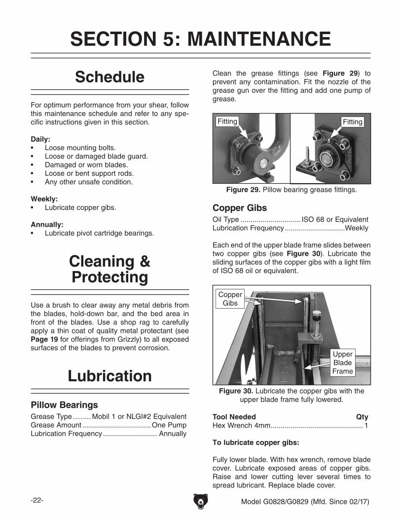
G8780—Portable Hand PunchProducing 1 ton of force, this hand punch has a 16-gauge capacity in mild steel, brass and aluminum. Much quicker and safer than drilling thin stock and leaves no ragged edges. Includes 3/32", 1/8", 5/32", 3/16", 7/32", 1/4" and 9/32" dies and wrenches.
Figure 27. Model G8780 Portable Hand Punch.
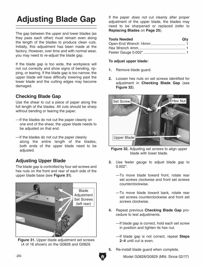
H2867—Electric Sheet-Metal ShearThis electric sheet-metal shear is double insu-lated and features a 110V, 2.4A motor with 4500 strokes per minute. Width of cut: 5/32". Cuts 1/16" mild steel and 3/64" stainless steel. Weighs 4 lbs. Made in an ISO 9001 factory.
Figure 26. Model H2867 Electric Sheet Metal Shear.
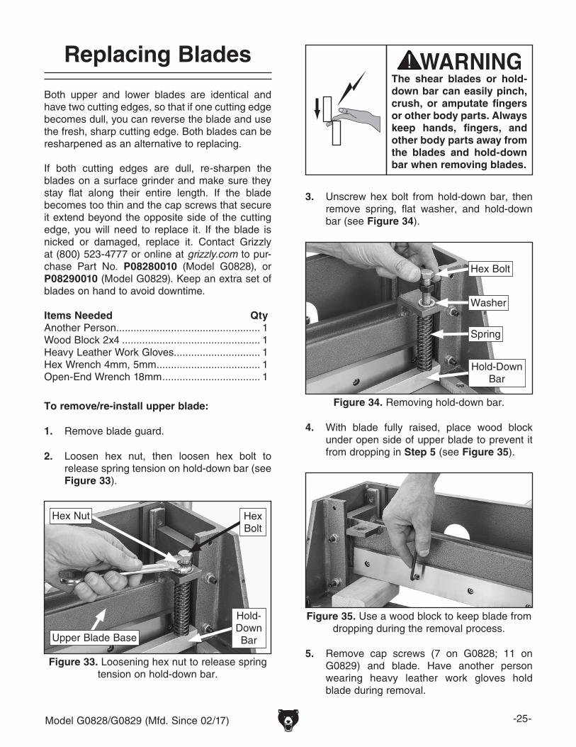
T23085 —Pneumatic NibblerThis pneumatic nibbler features a lightweight aluminum housing and cuts up to 16-gauge steel without leaving burrs or deformed edges. Adjustable die can be turned to suit various cut-ting positions. Cuts at 3800 strokes per minute. Features 1/4" NPT air inlet and working pressure of 90 PSI.
Figure 28. Model T23085 Pneumatic Nibbler.
-22- Model G0828/G0829 (Mfd. Since 02/17)
Lubrication
SECTION 5: MAINTENANCE
For optimum performance from your shear, follow this maintenance schedule and refer to any spe-cific instructions given in this section.
Daily:• Loose mounting bolts.• Loose or damaged blade guard.• Damaged or worn blades.• Loose or bent support rods.• Any other unsafe condition.
Weekly:• Lubricate copper gibs.
Annually:• Lubricate pivot cartridge bearings.
Schedule
Cleaning & Protecting
Use a brush to clear away any metal debris from the blades, hold-down bar, and the bed area in front of the blades. Use a shop rag to carefully apply a thin coat of quality metal protectant (see Page 19 for offerings from Grizzly) to all exposed surfaces of the blades to prevent corrosion.
Pillow BearingsGrease Type ......... Mobil 1 or NLGI#2 EquivalentGrease Amount ..................................One PumpLubrication Frequency ........................... Annually
Copper GibsOil Type .............................. ISO 68 or EquivalentLubrication Frequency ..............................Weekly
Each end of the upper blade frame slides between two copper gibs (see Figure 30). Lubricate the sliding surfaces of the copper gibs with a light film of ISO 68 oil or equivalent.
Fully lower blade. With hex wrench, remove blade cover. Lubricate exposed areas of copper gibs. Raise and lower cutting lever several times to spread lubricant. Replace blade cover.
Figure 29. Pillow bearing grease fittings.
FittingFitting
Figure 30. Lubricate the copper gibs with the upper blade frame fully lowered.
Copper Gibs
Upper Blade Frame
Clean the grease fittings (see Figure 29) to prevent any contamination. Fit the nozzle of the grease gun over the fitting and add one pump of grease.
Model G0828/G0829 (Mfd. Since 02/17) -23-
Review the troubleshooting and procedures in this section if a problem develops with your machine. If you need replacement parts or additional help with a procedure, call our Technical Support. Note: Please gather the serial number and manufacture date of your machine before calling.
SECTION 6: SERVICE
Troubleshooting
Symptom Possible Cause Possible SolutionShear will not cut workpiece.
1. Workpiece thickness exceeds shear capacity.
2. Blades worn or damaged.3. Blade gap not correct.4. Not enough pressure applied to cutting
lever.
1. Only use workpiece material that is within shear capacity (Pages 5–6).
2. Sharpen/replace blades (Page 25).3. Properly adjust blade gap (Page 24).3. Safely increase pressure on cutting lever.
Cuts are not square. 1. 90° guide not square with blades.2. Rear work stop not parallel to blades.
3. Hold-down bar not properly securing workpiece during cut.
4. Blade gap not correct.
1. Adjust 90° guide square with blades (Page 18).2. Properly adjust rear work stop parallel to blades
(Page 17).3. Adjust hold-down bar for even pressure on
workpiece (Page 16).4. Properly adjust blade gap (Page 24).
Poor quality of cuts (ripping or tearing).
1. Blade gap not correct.2. Blades worn or damaged.3. Gibs too loose.
Arm difficult to use. 1. Blade gap not correct.2. Cutting lever movement difficult.
3. Gibs too tight.
1. Properly adjust blade gap (Page 24).2. Lubricate pillow bearings (Page 22) and copper gibs
(Page 22).3. Properly adjust gibs (Page 27).
-24- Model G0828/G0829 (Mfd. Since 02/17)
Adjusting Blade Gap
The gap between the upper and lower blades (as they pass each other) must remain even along the length of the blades to produce clean cuts. Initially, this adjustment has been made at the factory. However, over time and with normal wear, you may need to re-adjust the blade gap.
If the blade gap is too wide, the workpiece will not cut correctly and show signs of bending, rip-ping, or tearing. If the blade gap is too narrow, the upper blade will have difficulty lowering past the lower blade and the cutting edges may become damaged.
Checking Blade GapUse the shear to cut a piece of paper along the full length of the blades. All cuts should be sharp without bending or tearing the paper.
—If the blades do not cut the paper cleanly onone end of the shear, the upper blade needs to be adjusted on that end.
—If the blades do not cut the paper cleanlyalong the entire length of the blades, both ends of the upper blade need to be adjusted.
Adjusting Upper BladeThe blade gap is controlled by four set screws and hex nuts on the front and rear of each side of the upper blade base (see Figure 31).
2. Loosen hex nuts on set screws identified for adjustment in Checking Blade Gap (see Figure 32).
If the paper does not cut cleanly after proper adjustment of the upper blade, the blades may need to be sharpened or replaced (refer to Replacing Blades on Page 25).
3. Use feeler gauge to adjust blade gap to 0.002":
— To move blade toward front, rotate rear set screws clockwise and front set screws counterclockwise.
— To move blade toward back, rotate rear set screws counterclockwise and front set screws clockwise.
4. Repeat previous Checking Blade Gap pro-cedure to test adjustments.
— If blade gap is correct, hold each set screw in position and tighten its hex nut.
— If blade gap is not correct, repeat Steps 2–4 until cut is even.
5. Re-install blade guard when complete.
Figure 31. Upper blade adjustment set screws (4 of 16 shown) on the G0828 and G0829.
Blade Adjustment Set Screws (left rear)
Figure 32. Adjusting set screws to align upper blade with lower blade.
Upper Blade
Set Screw Hex Nut
Model G0828/G0829 (Mfd. Since 02/17) -25-
Replacing Blades
Both upper and lower blades are identical and have two cutting edges, so that if one cutting edge becomes dull, you can reverse the blade and use the fresh, sharp cutting edge. Both blades can be resharpened as an alternative to replacing.
If both cutting edges are dull, re-sharpen the blades on a surface grinder and make sure they stay flat along their entire length. If the blade becomes too thin and the cap screws that secure it extend beyond the opposite side of the cutting edge, you will need to replace it. If the blade is nicked or damaged, replace it. Contact Grizzly at (800) 523-4777 or online at grizzly.com to pur-chase Part No. P08280010 (Model G0828), or P08290010 (Model G0829). Keep an extra set of blades on hand to avoid downtime.
2. Loosen hex nut, then loosen hex bolt to release spring tension on hold-down bar (see Figure 33).
1. Remove blade guard.
3. Unscrew hex bolt from hold-down bar, then remove spring, flat washer, and hold-down bar (see Figure 34).
4. With blade fully raised, place wood block under open side of upper blade to prevent it from dropping in Step 5 (see Figure 35).
The shear blades or hold-down bar can easily pinch, crush, or amputate fingers or other body parts. Always keep hands, fingers, and other body parts away from the blades and hold-down bar when removing blades.
5. Remove cap screws (7 on G0828; 11 on G0829) and blade. Have another person wearing heavy leather work gloves hold blade during removal.
Figure 33. Loosening hex nut to release spring tension on hold-down bar.
Hex Nut
Upper Blade Base
Hold-Down Bar
Hex Bolt
Figure 34. Removing hold-down bar.
Hold-Down Bar
Hex Bolt
Washer
Spring
Figure 35. Use a wood block to keep blade from dropping during the removal process.
-26- Model G0828/G0829 (Mfd. Since 02/17)
7. Reverse Steps 1–5 to re-install blade.
6. Clean blade with mineral spirits, then apply thin coat of quality metal protectant before re-installing blade.
To remove/re-install lower blade:
3. Loosen cap screws securing lower blade to frame (see Figure 37). G0828 uses 7 cap screws; G0829 uses 11 cap screws.
Figure 36. Remove rear lower cover cap screws to access lower blade (G0828 shown).
Remove Cap
Screws
Figure 37. Lower blade removal (viewed from bottom).
4. Have another person wearing heavy leather work gloves support blade and remove it.
5. Clean blade with mineral spirits, then apply thin coat of quality metal protectant before re-installing blade.
6. Reverse Steps 1–3 to re-install blade.
7. Check and adjust blade gap, following proce-dures on Page 24.
2. Remove (2) outer cap screws from lower cover, and cap screws (3 on G0828; 5 on G0829) from upper cover (see Figure 36).
1. Loosen cap screws securing support rods to rear work stop assembly. Remove assembly.
Lower Blade
Model G0828/G0829 (Mfd. Since 02/17) -27-
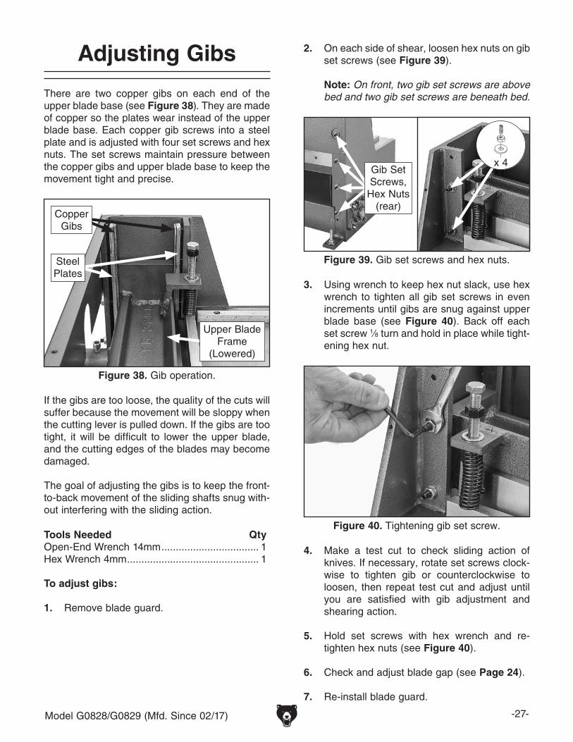
Adjusting Gibs
There are two copper gibs on each end of the upper blade base (see Figure 38). They are made of copper so the plates wear instead of the upper blade base. Each copper gib screws into a steel plate and is adjusted with four set screws and hex nuts. The set screws maintain pressure between the copper gibs and upper blade base to keep the movement tight and precise.
If the gibs are too loose, the quality of the cuts will suffer because the movement will be sloppy when the cutting lever is pulled down. If the gibs are too tight, it will be difficult to lower the upper blade, and the cutting edges of the blades may become damaged.
The goal of adjusting the gibs is to keep the front-to-back movement of the sliding shafts snug with-out interfering with the sliding action.
2. On each side of shear, loosen hex nuts on gib set screws (see Figure 39).
Note: On front, two gib set screws are above bed and two gib set screws are beneath bed.
4. Make a test cut to check sliding action of knives. If necessary, rotate set screws clock-wise to tighten gib or counterclockwise to loosen, then repeat test cut and adjust until you are satisfied with gib adjustment and shearing action.
5. Hold set screws with hex wrench and re-tighten hex nuts (see Figure 40).
6. Check and adjust blade gap (see Page 24).
7. Re-install blade guard.
Figure 40. Tightening gib set screw.
3. Using wrench to keep hex nut slack, use hex wrench to tighten all gib set screws in even increments until gibs are snug against upper blade base (see Figure 40). Back off each set screw 1⁄8 turn and hold in place while tight-ening hex nut.
Figure 38. Gib operation.
Copper Gibs
Upper Blade Frame
(Lowered)
Steel Plates
Figure 39. Gib set screws and hex nuts.
x 4Gib Set Screws,
Hex Nuts (rear)
-28- Model G0828/G0829 (Mfd. Since 02/17)
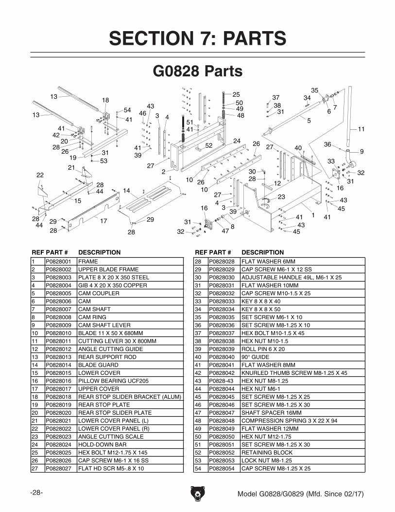
SECTION 7: PARTS
15
31
5
8
16
47
4
67
34
1
2
3
4
10 12
13
14
18
19
20
2122
23
24
25
26
27
28
30
353738
39
40
41
42
434445
46 484950
51
52
53
29
10
3
43
4139
28 172928
54
31
41
13
31
9
11
32
33
36
164428
2628
41
31
27
26
27
28
41 41
4345
32
G0828 Parts
REF PART # DESCRIPTION REF PART # DESCRIPTION1 P0828001 FRAME 28 P0828028 FLAT WASHER 6MM2 P0828002 UPPER BLADE FRAME 29 P0828029 CAP SCREW M6-1 X 12 SS3 P0828003 PLATE 8 X 20 X 350 STEEL 30 P0828030 ADJUSTABLE HANDLE 49L, M6-1 X 254 P0828004 GIB 4 X 20 X 350 COPPER 31 P0828031 FLAT WASHER 10MM5 P0828005 CAM COUPLER 32 P0828032 CAP SCREW M10-1.5 X 256 P0828006 CAM 33 P0828033 KEY 8 X 8 X 407 P0828007 CAM SHAFT 34 P0828034 KEY 8 X 8 X 508 P0828008 CAM RING 35 P0828035 SET SCREW M6-1 X 10⁹ P0828009 CAM SHAFT LEVER 36 P0828036 SET SCREW M8-1.25 X 10¹⁰ P0828010 BLADE 11 X 50 X 680MM 37 P0828037 HEX BOLT M10-1.5 X 4511 P0828011 CUTTING LEVER 30 X 800MM 38 P0828038 HEX NUT M10-1.512 P0828012 ANGLE CUTTING GUIDE 39 P0828039 ROLL PIN 6 X 2013 P0828013 REAR SUPPORT ROD 40 P0828040 90° GUIDE14 P0828014 BLADE GUARD 41 P0828041 FLAT WASHER 8MM15 P0828015 LOWER COVER 42 P0828042 KNURLED THUMB SCREW M8-1.25 X 4516 P0828016 PILLOW BEARING UCF205 43 P0828-43 HEX NUT M8-1.2517 P0828017 UPPER COVER 44 P0828044 HEX NUT M6-118 P0828018 REAR STOP SLIDER BRACKET (ALUM) 45 P0828045 SET SCREW M8-1.25 X 2519 P0828019 REAR STOP PLATE 46 P0828046 SET SCREW M8-1.25 X 3020 P0828020 REAR STOP SLIDER PLATE 47 P0828047 SHAFT SPACER 16MM21 P0828021 LOWER COVER PANEL (L) 48 P0828048 COMPRESSION SPRING 3 X 22 X 9422 P0828022 LOWER COVER PANEL (R) 49 P0828049 FLAT WASHER 12MM23 P0828023 ANGLE CUTTING SCALE 50 P0828050 HEX NUT M12-1.7524 P0828024 HOLD-DOWN BAR 51 P0828051 SET SCREW M8-1.25 X 3025 P0828025 HEX BOLT M12-1.75 X 145 52 P0828052 RETAINING BLOCK26 P0828026 CAP SCREW M6-1 X 16 SS 53 P0828053 LOCK NUT M8-1.2527 P0828027 FLAT HD SCR M5-.8 X 10 54 P0828054 CAP SCREW M8-1.25 X 25
Model G0828/G0829 (Mfd. Since 02/17) -29-
1
2
34
5
6
7 8
9
10
11
12
13
14
15
16
17
18
19
20
21
22
23
24
25
2627
28
29
30
3132
3334
3536
3738
39
40
41
42
43
44
45 46
47
484950
51
52
53
54
16
31
39
78
29
4242
28
42
38
3 4
43
42
2827
2829
10
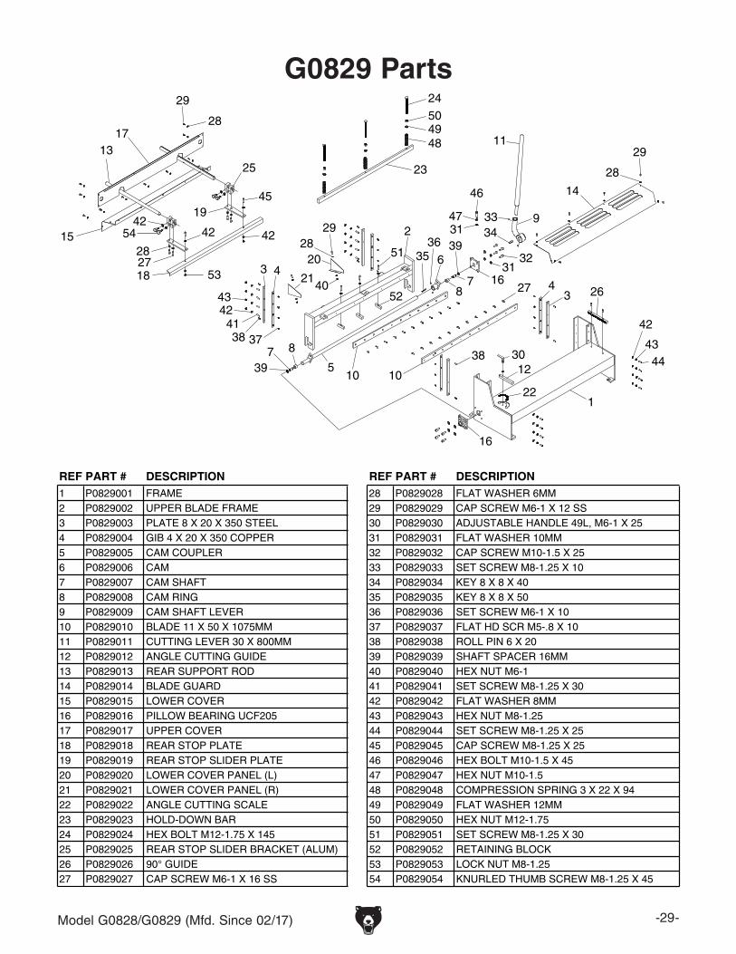
G0829 Parts
REF PART # DESCRIPTION REF PART # DESCRIPTION1 P0829001 FRAME 28 P0829028 FLAT WASHER 6MM2 P0829002 UPPER BLADE FRAME 29 P0829029 CAP SCREW M6-1 X 12 SS3 P0829003 PLATE 8 X 20 X 350 STEEL 30 P0829030 ADJUSTABLE HANDLE 49L, M6-1 X 254 P0829004 GIB 4 X 20 X 350 COPPER 31 P0829031 FLAT WASHER 10MM5 P0829005 CAM COUPLER 32 P0829032 CAP SCREW M10-1.5 X 256 P0829006 CAM 33 P0829033 SET SCREW M8-1.25 X 10⁷ P0829007 CAM SHAFT 34 P0829034 KEY 8 X 8 X 408 P0829008 CAM RING 35 P0829035 KEY 8 X 8 X 509 P0829009 CAM SHAFT LEVER 36 P0829036 SET SCREW M6-1 X 10¹⁰ P0829010 BLADE 11 X 50 X 1075MM 37 P0829037 FLAT HD SCR M5-.8 X 1011 P0829011 CUTTING LEVER 30 X 800MM 38 P0829038 ROLL PIN 6 X 2012 P0829012 ANGLE CUTTING GUIDE 39 P0829039 SHAFT SPACER 16MM13 P0829013 REAR SUPPORT ROD 40 P0829040 HEX NUT M6-114 P0829014 BLADE GUARD 41 P0829041 SET SCREW M8-1.25 X 3015 P0829015 LOWER COVER 42 P0829042 FLAT WASHER 8MM16 P0829016 PILLOW BEARING UCF205 43 P0829043 HEX NUT M8-1.2517 P0829017 UPPER COVER 44 P0829044 SET SCREW M8-1.25 X 2518 P0829018 REAR STOP PLATE 45 P0829045 CAP SCREW M8-1.25 X 2519 P0829019 REAR STOP SLIDER PLATE 46 P0829046 HEX BOLT M10-1.5 X 4520 P0829020 LOWER COVER PANEL (L) 47 P0829047 HEX NUT M10-1.521 P0829021 LOWER COVER PANEL (R) 48 P0829048 COMPRESSION SPRING 3 X 22 X 9422 P0829022 ANGLE CUTTING SCALE 49 P0829049 FLAT WASHER 12MM23 P0829023 HOLD-DOWN BAR 50 P0829050 HEX NUT M12-1.7524 P0829024 HEX BOLT M12-1.75 X 145 51 P0829051 SET SCREW M8-1.25 X 3025 P0829025 REAR STOP SLIDER BRACKET (ALUM) 52 P0829052 RETAINING BLOCK26 P0829026 90° GUIDE 53 P0829053 LOCK NUT M8-1.2527 P0829027 CAP SCREW M6-1 X 16 SS 54 P0829054 KNURLED THUMB SCREW M8-1.25 X 45
-30- Model G0828/G0829 (Mfd. Since 02/17)
81
82
82
83 84
85
85
86
81
83 84
86
Labels & Cosmetics
REF PART # DESCRIPTION REF PART # DESCRIPTION81 P0828081 SAFETY GLASSES LABEL 85 P0828085 MODEL NUMBER LABEL (G0828)82 P0828082 MACHINE ID LABEL (G0828) 85 P0829085 MODEL NUMBER LABEL (G0829)82 P0829082 MACHINE ID LABEL (G0829) 86 P0828086 GRIZZLY.COM LABEL83 P0828083 READ MANUAL LABEL 87 P0828087 TOUCH-UP PAINT, GRIZZLY GREEN84 P0828084 AMPUTATION DANGER LABEL
Safety labels help reduce the risk of serious injury caused by machine hazards. If any label comes off or becomes unreadable, the owner of this machine MUST replace it in the original location before resuming operations. For replacements, contact (800) 523-4777 or www.grizzly.com.
Note: Labels on both machines are identical except for machine identification and model number.
G0829
G0828
CU
T A
LON
G D
OT
TE
D L
INE
Name _____________________________________________________________________________
Street _____________________________________________________________________________
City _______________________ State _________________________ Zip _____________________
Model # ____________________ Order # _______________________ Serial # __________________
WARRANTY CARD
The following information is given on a voluntary basis. It will be used for marketing purposes to help us develop better products and services. Of course, all information is strictly confidential.
1. How did you learn about us? ____ Advertisement ____ Friend ____ Catalog ____ Card Deck ____ Website ____ Other:
2. Which of the following magazines do you subscribe to?
3. What is your annual household income? ____ $20,000-$29,000 ____ $30,000-$39,000 ____ $40,000-$49,000 ____ $50,000-$59,000 ____ $60,000-$69,000 ____ $70,000+
4. What is your age group? ____ 20-29 ____ 30-39 ____ 40-49 ____ 50-59 ____ 60-69 ____ 70+
5. How long have you been a woodworker/metalworker? ____ 0-2 Years ____ 2-8 Years ____ 8-20 Years ____20+ Years
6. How many of your machines or tools are Grizzly? ____ 0-2 ____ 3-5 ____ 6-9 ____10+
7. Do you think your machine represents a good value? _____Yes _____No
8. Would you recommend Grizzly Industrial to a friend? _____Yes _____No
9. Would you allow us to use your name as a reference for Grizzly customers in your area? Note: We never use names more than 3 times. _____Yes _____No
____ Cabinetmaker & FDM____ Family Handyman____ Hand Loader____ Handy____ Home Shop Machinist____ Journal of Light Cont.____ Live Steam____ Model Airplane News____ Old House Journal____ Popular Mechanics
____ Popular Science____ Popular Woodworking____ Precision Shooter____ Projects in Metal____ RC Modeler____ Rifle____ Shop Notes____ Shotgun News____ Today’s Homeowner____ Wood
GRIZZLY INDUSTRIAL, INC.P.O. BOX 2069BELLINGHAM, WA 98227-2069
PlaceStampHere
Name_______________________________
Street_______________________________
City______________State______Zip______
Send a Grizzly Catalog to a friend:
WARRANTY & RETURNSGrizzly Industrial, Inc. warrants every product it sells for a period of 1 year to the original purchaser from the date of purchase. This warranty does not apply to defects due directly or indirectly to misuse, abuse, negligence, accidents, repairs or alterations or lack of maintenance. This is Grizzly’s sole written warranty and any and all warranties that may be implied by law, including any merchantability or fitness, for any par-ticular purpose, are hereby limited to the duration of this written warranty. We do not warrant or represent that the merchandise complies with the provisions of any law or acts unless the manufacturer so warrants. In no event shall Grizzly’s liability under this warranty exceed the purchase price paid for the product and any legal actions brought against Grizzly shall be tried in the State of Washington, County of Whatcom.
We shall in no event be liable for death, injuries to persons or property or for incidental, contingent, special, or consequential damages arising from the use of our products.
To take advantage of this warranty, contact us by mail or phone and give us all the details. We will then issue you a “Return Number,’’ which must be clearly posted on the outside as well as the inside of the carton. We will not accept any item back without this number. Proof of purchase must accompany the merchandise.
The manufacturers reserve the right to change specifications at any time because they constantly strive to achieve better quality equipment. We make every effort to ensure that our products meet high quality and durability standards and we hope you never need to use this warranty.
Please feel free to write or call us if you have any questions about the machine or the manual.
Thank you again for your business and continued support. We hope to serve you again soon.