Page 1
Hybrid Control of a 3-D Structure by using Seismic isolators and Semi-Active Dampers
Role of Research Infrastructers in seismic rehabilitationFebruary 8-9, 2012 – İTÜ – İstanbul
Gürsoy Turanİzmir Yüksek Teknoloji Enstitüsü
[email protected]
(sponsored by TÜBİTAK, Grant No: 107M353)
Page 2
Goal
During strong seismic ground motions
➲ Base isolators shall not rupture
➲ Structural response should not be badly affected
Seismic Isolator - Structural displacement displacement
2/22
Page 3
Goal
During strong seismic ground motions
➲ Base isolators shall not rupture
➲ Structural response should not be badly affected
Seismic Isolator - Structural displacement displacement
2/22
Page 4
Goal
During strong seismic ground motions
➲ Base isolators shall not rupture
➲ Structural response should not be badly affected
Seismic Isolator - Structural displacement displacement
2/22
Page 5
Outline
➲ Intro: Control of Seismic isolated Structures➲ 3-story building model➲ semi active hydraulic damper➲ Control Design
● Linear Quadratic Regulator(LQR)● Upper Controller
➲ Response simulation➲ Results
3/22
Page 6
Outline
➲ Intro: Control of Seismic isolated Structures➲ 3-story building model➲ semi active hydraulic damper➲ Control Design
● Linear Quadratic Regulator(LQR)● Upper Controller
➲ Response simulation➲ Results
3/22
Page 7
Outline
➲ Intro: Control of Seismic isolated Structures➲ 3-story building model➲ semi active hydraulic damper➲ Control Design
● Linear Quadratic Regulator(LQR)● Upper Controller
➲ Response simulation➲ Results
3/22
Page 8
Outline
➲ Intro: Control of Seismic isolated Structures➲ 3-story building model➲ semi active hydraulic damper➲ Control Design
● Linear Quadratic Regulator(LQR)● Upper Controller
➲ Response simulation➲ Results
3/22
Page 9
Outline
➲ Intro: Control of Seismic isolated Structures➲ 3-story building model➲ semi active hydraulic damper➲ Control Design
● Linear Quadratic Regulator(LQR)● Upper Controller
➲ Response simulation➲ Results
3/22
Page 10
Outline
➲ Intro: Control of Seismic isolated Structures➲ 3-story building model➲ semi active hydraulic damper➲ Control Design
● Linear Quadratic Regulator(LQR)● Upper Controller
➲ Response simulation➲ Results
3/22
Page 14
Introduction
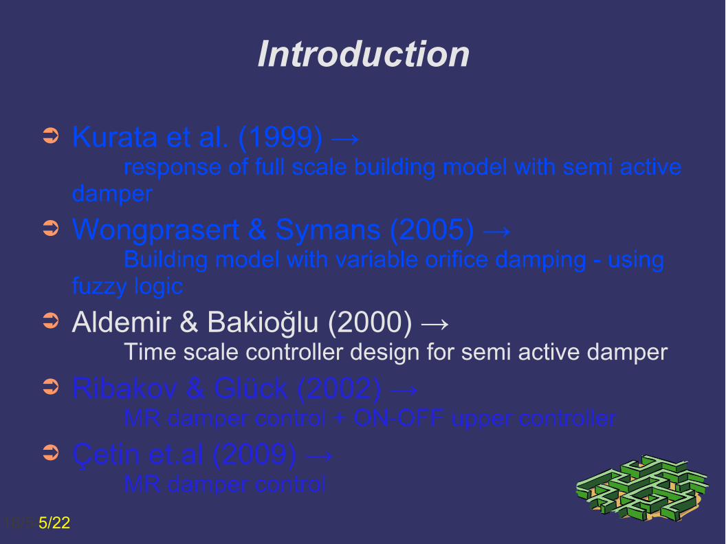
➲ Kurata et al. (1999) → response of full scale building model with semi active
damper
➲ Wongprasert & Symans (2005) → Building model with variable orifice damping - using
fuzzy logic
➲ Aldemir & Bakioğlu (2000) → Time scale controller design for semi active damper
➲ Ribakov & Glück (2002) →MR damper control + ON-OFF upper controller
➲ Çetin et.al (2009) → MR damper control
14/545/22
Page 15
Introduction
➲ Kurata et al. (1999) → response of full scale building model with semi active
damper
➲ Wongprasert & Symans (2005) → Building model with variable orifice damping - using
fuzzy logic
➲ Aldemir & Bakioğlu (2000) → Time scale controller design for semi active damper
➲ Ribakov & Glück (2002) →MR damper control + ON-OFF upper controller
➲ Çetin et.al (2009) → MR damper control
15/545/22
Page 16
Introduction
➲ Kurata et al. (1999) → response of full scale building model with semi active
damper
➲ Wongprasert & Symans (2005) → Building model with variable orifice damping - using
fuzzy logic
➲ Aldemir & Bakioğlu (2000) → Time scale controller design for semi active damper
➲ Ribakov & Glück (2002) →MR damper control + ON-OFF upper controller
➲ Çetin et.al (2009) → MR damper control
16/545/22
Page 17
Introduction
➲ Kurata et al. (1999) → response of full scale building model with semi active
damper
➲ Wongprasert & Symans (2005) → Building model with variable orifice damping - using
fuzzy logic
➲ Aldemir & Bakioğlu (2000) → Time scale controller design for semi active damper
➲ Ribakov & Glück (2002) →MR damper control + ON-OFF upper controller
➲ Çetin et.al (2009) → MR damper control
17/545/22
Page 18
Introduction
➲ Kurata et al. (1999) → response of full scale building model with semi active
damper
➲ Wongprasert & Symans (2005) → Building model with variable orifice damping - using
fuzzy logic
➲ Aldemir & Bakioğlu (2000) → Time scale controller design for semi active damper
➲ Ribakov & Glück (2002) →MR damper control + ON-OFF upper controller
➲ Çetin et.al (2009) → MR damper control
18/545/22
Page 19
Building Model
➲ 3 stories4 columns, H=0.82m / story, rigid beamsMass 200kg/story
➲ Seismic isolator, H= 4cmE
y= 4000 Pa
6/22
Page 20
Building Model
6/22
f9 = 6.68 Hz
f10
= 7.60 Hz
f11
= 8.02 Hz
f12
= 9.22 Hz
f13
=111.00 Hz
f14
=111.80 Hz
f15
=112.50 Hz
f16
=124.50 Hz
f1 = 0.31 Hz
f2 = 0.32 Hz
f3 = 0.34 Hz
f4 = 3.11 Hz
f5 = 3.33 Hz
f6 = 3.60 Hz
f7 = 5.92 Hz
f8 = 6.05 Hz
➲ 3 stories4 columns, H=0.82m / story, rigid beamsMass 200kg/story
➲ Seismic isolator, H= 4cmE
y= 4000 Pa
Page 22
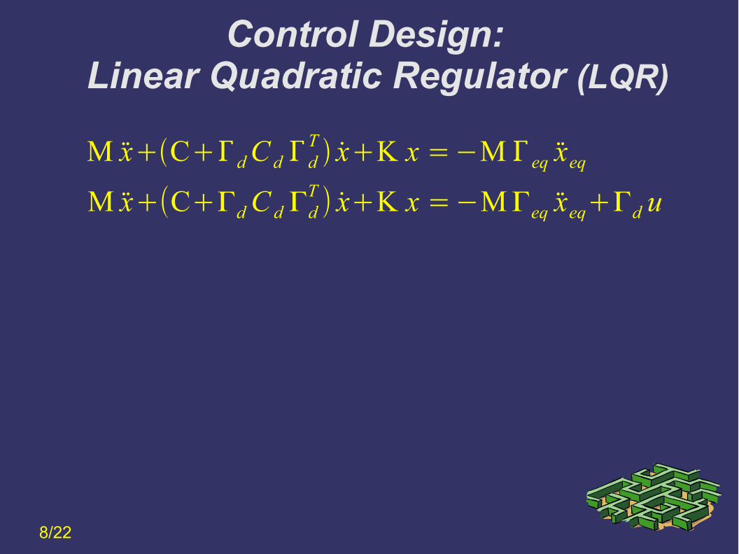
Control Design: Linear Quadratic Regulator (LQR)
M xCdC d dT xK x =−M eq xeq
8/22
Page 23
Control Design: Linear Quadratic Regulator (LQR)
M xCdC d dT xK x =−M eq xeq
M x+(C+ΓdC d ΓdT ) x+K x =−MΓeq xeq+Γd u
8/22
Page 24
2nd order diff. Equation --> 1st order diff.Eqn.
Control Design: Linear Quadratic Regulator (LQR)
M xCdC d dT xK x =−M eq xeq
q=AqB1 x gB2u
M xCdC d dT xK x =−M eq xeq d u
8/22
Page 25
Control Design: Linear Quadratic Regulator (LQR)
M xCdC d dT xK x =−M eq xeq
q=AqB1 x gB2u
A= [ 0 I−M−1 K −M−1 CdC d d
T ] B1= [ 0eq ] B2= [ 0
M−1 d]
2nd order diff. Equation --> 1st order diff.Eqn.
Here, q= [ x x ]T
M xCdC d dT xK x =−M eq xeq d u
8/22
Page 26
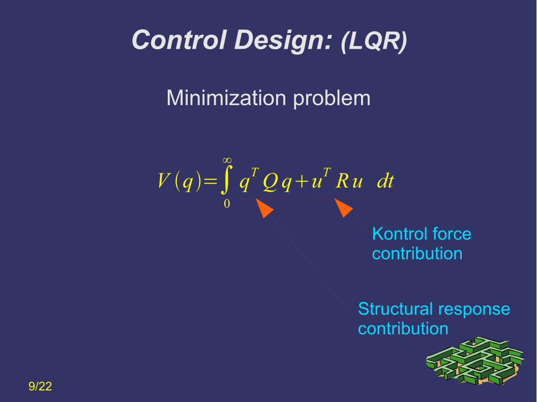
V q=∫0
∞
qTQquT Ru dt
Minimization problem
Kontrol force contribution
Structural response contribution
9/22
Control Design: (LQR)
Page 27
uo=−R−1B2T P qo
The optimal control force that minimizes the problem definition
AT PP AQ−P B2 R−1B2
T P=0
Here, P is the solution to the following Ricatti equation
10/22
Control Design: (LQR)
Page 28
Control Design: Upper Controller
➲ Damping levels: 5000 : 5000 : 25000 Ns/m5 positions / damper
➲ No. of dampers = 4
11/22
Therefore➲ 625 damping configurations, and thus➲ 625 optimal control equations
(The minimization problem is solved for 625 different configurations)
Page 29
Control Design: Upper Controller
➲ Damping levels: 5000 : 5000 : 25000 Ns/m5 positions / damper
➲ No. of dampers = 4
Therefore➲ 625 damping configurations, and thus➲ 625 optimal control equations
(The minimization problem is solved for 625 different configurations)
11/22
Page 30
Control Design: Upper Controller
12/22
➲ dbase
< 15mm → minimum damping
➲ dbase
> 15mm → optimal damping
Page 32
Control Design: Upper Controller
At time ti, the upper controller
➲ calculates the optimal control force, u
➲ calculates the closest damping force to achieve the desired optimal control force
➲ switches to the calculated damping state
13/22
Page 33
Control Design: Upper Controller
At time ti, the upper controller
➲ calculates the optimal control force, u
➲ calculates the closest damping force to achieve the desired optimal control force
➲ switches to the calculated damping state
13/22
Page 34
At time ti, the upper controller
➲ calculates the optimal control force, u
➲ calculates the closest damping force to achieve the desired optimal control force
➲ switches to the calculated damping state
Control Design: Upper Controller
13/22
Page 35
14/22
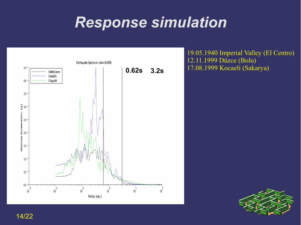
19.05.1940 Imperial Valley (El Centro) 12.11.1999 Düzce (Bolu)17.08.1999 Kocaeli (Sakarya)
Selected Earthquakes
Response simulation
Page 36
0.62s 3.2s
14/22
19.05.1940 Imperial Valley (El Centro) 12.11.1999 Düzce (Bolu)17.08.1999 Kocaeli (Sakarya)
Response simulation
Page 37
0.62s 3.2s
14/22
19.05.1940 Imperial Valley (El Centro) 12.11.1999 Düzce (Bolu)17.08.1999 Kocaeli (Sakarya)
Response simulation
Page 42
Response simulation
15/22
Base Displacement: 1940ELCentroD
ispl
acem
ent,
{m
}
time, {s}
controlled
Page 43
Response simulation
16/22
Dis
plac
emen
t, {
m}
time, {s}
1st story Displacement: 1940ELCentro
controlled
Page 44
Response simulation
19/22
Base Displacement: 12KasBoluD
ispl
acem
ent,
{m
}
time, {s}
controlled
Page 45
Response simulation
18/22
Dis
plac
emen
t, {
m}
time, {s}
1st story Displacement: 12KasBolu
controlled
Page 46
19/22
Dis
plac
emen
t, {m
}
time, {s}
Base Displacement: 17AguSKR
controlled
Page 47
Response simulation
20/22
Dis
plac
emen
t, {
m}
time, {s}
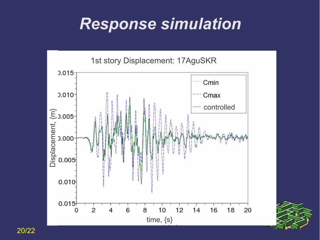
1st story Displacement: 17AguSKR
controlled
Page 50
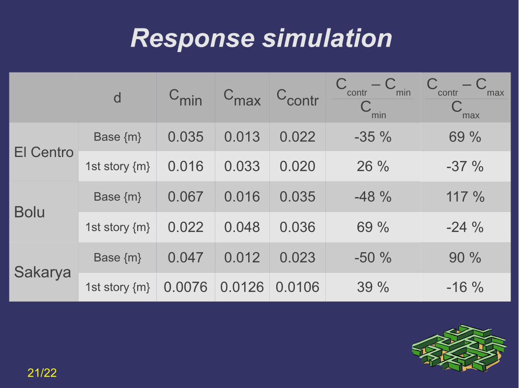
Ccontr
– Cmax
Cmax
69 %
-37 %
117 %
-24 %
90 %
-16 %
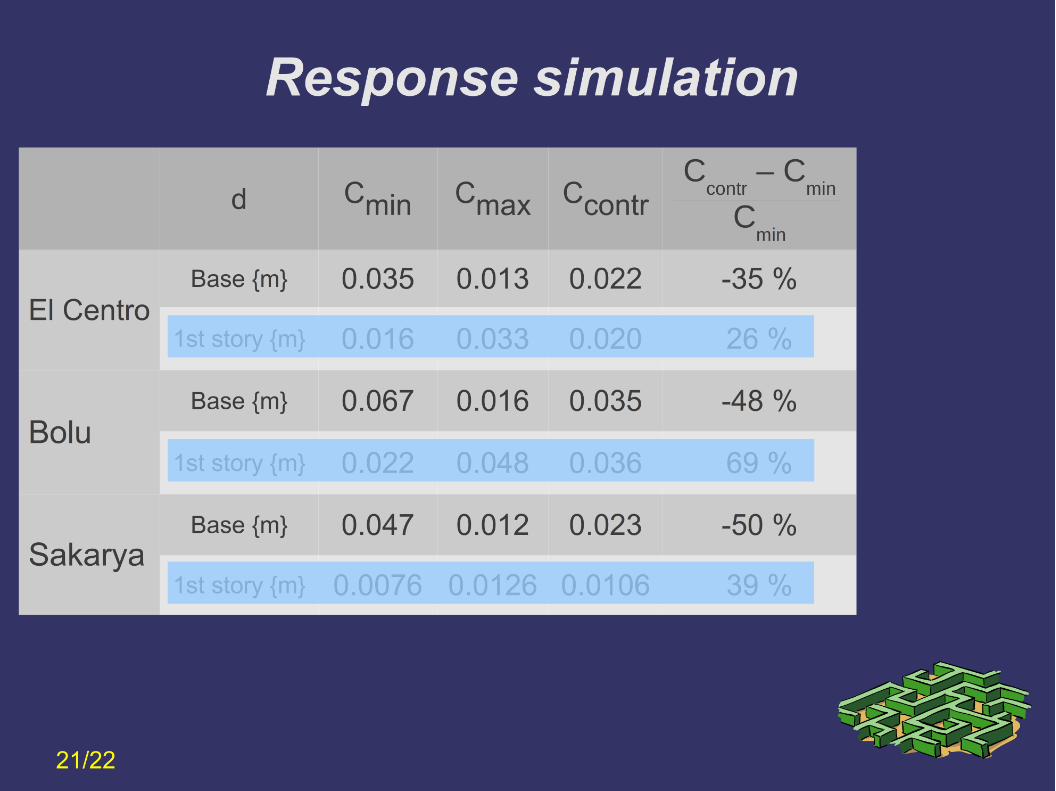
d Cmin Cmax CcontrC
contr – C
min
Cmin
El CentroBase {m} 0.035 0.013 0.022 -35 %
1st story {m} 0.016 0.033 0.020 26 %
BoluBase {m} 0.067 0.016 0.035 -48 %
1st story {m} 0.022 0.048 0.036 69 %
SakaryaBase {m} 0.047 0.012 0.023 -50 %
1st story {m} 0.0076 0.0126 0.0106 39 %
Response simulation
21/22
Page 51
Results
Benefits of using base isolators together with semi active dampers
➲ Isolator displacement is reduced (%35-%50 reduction w.r.t. min. damping case).
➲ No significant increase in 1st story displacement response (%16-%37 w.r.t. max. damping)
➲ This control system is robust because energy is only introduced to change the valve positions of the dampers
51/5422/22
Page 52
Results
Benefits of using base isolators together with semi active dampers
➲ Isolator displacement is reduced (%35-%50 reduction w.r.t. min. damping case).
➲ No significant increase in 1st story displacement response (%16-%37 w.r.t. max. damping)
➲ This control system is robust because energy is only introduced to change the valve positions of the dampers
52/5422/22
Page 53
Results
Benefits of using base isolators together with semi active dampers
➲ Isolator displacement is reduced (min. sönümlemeye göre 35-%50 azalmıştır.).
➲ No significant increase in 1st story displacement response (%16-%37 w.r.t. max. damping)
➲ This control system is robust because energy is only introduced to change the valve positions of the dampers
53/5422/22
Page 54
Thank you
Gürsoy Turanİzmir Yüksek Teknoloji Enstitüsü
[email protected]
(TÜBİTAK 107M353)