Subject to change without notice – Bernhard Schulz 01.05 – 1CM57 R&S CMU200 (K20,K21,K22,K23,K24), CMUgo GSM Measurements with the R&S CMU200 and CMUgo This Application Note describes how to test and perform measurements on mobile phones in compliance with the GSM standard using the R&S CMU200 by means of the remote-control program CMUgo or manual operation.
Transcript
Subject to change without notice – Bernhard Schulz 01.05 – 1CM57
R&S CMU200 (K20,K21,K22,K23,K24), CMUgo
GSM Measurements with the R&S CMU200
and CMUgo
This Application Note describes how to test and perform measurements on mobile phones in compliance
with the GSM standard using the R&S CMU200 by means of the remote-control program CMUgo or manual operation.
GSM with R&S CMU and CMUgo
1CM57 2 Rohde & Schwarz
Contents 1 Overview..................................................................................................3 2 Introduction ..............................................................................................3 3 Manual Operation of the R&S CMU200...................................................3
4 Remote Control of the R&S CMU200 with CMUgo ...............................18 Software features .............................................................................18 Hardware and software requirements ..............................................18
5 Appendix................................................................................................37 List of Figures ...................................................................................37 Remote Sequences ..........................................................................38
Abbreviations....................................................................................45 References .......................................................................................45 Additional information .......................................................................45
GSM with R&S CMU and CMUgo
1CM57 3 Rohde & Schwarz
1 Overview The Radio Communication Tester R&S CMU200 can be used to perform fast and accurate measurements of various standards such as GSM, IS-136, AMPS, CDMA, cdma2000, 1xEVDO, WCDMA and Bluetooth®1.
This Application Note describes how to use CMUgo, a Windows application for remote control of the R&S CMU200 and for measuring and testing mobile phones in compliance with the GSM standard.
2 Introduction Although the “old” 2nd generation GSM mobile radio standard is threatened by a 3rd generation (WCDMA, cdma2000), it has been expanded by the new functions EDGE and (E)GPRS (2.5 generation), which will surely extend its life-span. Most telephones on the market still use GSM or offer GSM as fallback options.
This Application Note intends to analyze aspects of the CMU in accordance with the pure GSM standard of the 2nd generation. A separat Application Note [3] deals with newer functions such as GPRS and EGPRS.
This Application Note does not attempt to explain the associated theory in full detail but rather simply provides a brief summary of the most important aspects.
3 Manual Operation of the R&S CMU200
Call setup and release
Auxiliary RF generator (AuxTX - option B95)
In the standard GSM environment, a single generator in the CMU is still sufficient for testing the mobile phones. Here, the CMU generates the BCCH in timeslot 0. Timeslots 1 and 7 are disabled due to settling times; timeslots 2 to 6 are therefore available for the TCH (Fig. 1).
Fig. 1 - Downlink on two channels without option B95
Fig. 2 shows the required CMU settings in the BS Signal tab. The BCCH Channel and TCH Channel parameters are particularly important here. The BCCH Level and the Main Timeslot can also be set here. The Mode parameter is only relevant for the conventional GSM mode; the BCCH can be disabled following call setup BCCH or TCH to allow measurements on all timeslots.
1)The Bluetooth word mark and logos are owned by the Bluetooth SIG, Inc. and any use of such marks by Rohde&Schwarz is under license.
GSM with R&S CMU and CMUgo
1CM57 4 Rohde & Schwarz
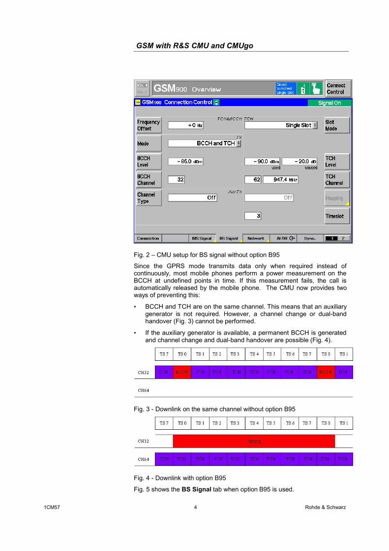
Fig. 2 – CMU setup for BS signal without option B95
Since the GPRS mode transmits data only when required instead of continuously, most mobile phones perform a power measurement on the BCCH at undefined points in time. If this measurement fails, the call is automatically released by the mobile phone. The CMU now provides two ways of preventing this:
• BCCH and TCH are on the same channel. This means that an auxiliary generator is not required. However, a channel change or dual-band handover (Fig. 3) cannot be performed.
• If the auxiliary generator is available, a permanent BCCH is generated and channel change and dual-band handover are possible (Fig. 4).
Fig. 3 - Downlink on the same channel without option B95
Fig. 4 - Downlink with option B95
Fig. 5 shows the BS Signal tab when option B95 is used.
GSM with R&S CMU and CMUgo
1CM57 5 Rohde & Schwarz
Fig. 5 – CMU setup for BS signal with option B95
A number of restrictions apply if the option B95 is used:
• Max. 2 W RMS can be applied at the RF1 connector.
• RF3 out cannot be used while option B95 is being used.
• A maximum of -60 dBm can be set as the BCCH level at RF2.
Analyzer mode
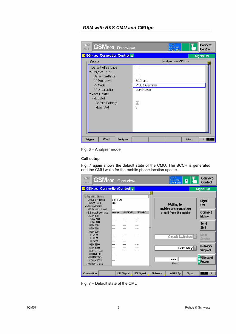
In GSM, the CMU generally has three modes in the signalling mode, and two of them ensure easy operation. In the AUTO mode, the CMU first measures the mobile phone power and automatically adjusts itself to this power. Due to this additional measurement, this mode is slower than the recommended PCL/Gamma mode. The CMU thus automatically adjusts to the mobile phone power expected due to the PCL value (Fig. 6). In the Manual mode, you have to set the required level manually.
GSM with R&S CMU and CMUgo
1CM57 6 Rohde & Schwarz
Fig. 6 – Analyzer mode
Call setup
Fig. 7 again shows the default state of the CMU. The BCCH is generated and the CMU waits for the mobile phone location update.
Fig. 7 – Default state of the CMU
GSM with R&S CMU and CMUgo
1CM57 7 Rohde & Schwarz
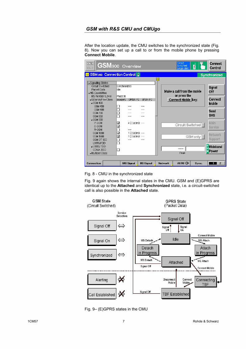
After the location update, the CMU switches to the synchronized state (Fig. 8). Now you can set up a call to or from the mobile phone by pressing Connect Mobile.
Fig. 8 - CMU in the synchronized state
Fig. 9 again shows the internal states in the CMU. GSM and (E)GPRS are identical up to the Attached and Synchronized state, i.e. a circuit-switched call is also possible in the Attached state.
Fig. 9– (E)GPRS states in the CMU
GSM with R&S CMU and CMUgo
1CM57 8 Rohde & Schwarz
If the CMU is in the Call Established state, you can perform the individual measurements.
Measurements The individual measurement menus are displayed in the lower row. Individual connection parameters (e.g. channel, PCL, etc) as well as measurement parameters can be varied in the column at the right edge.
Overview
The Overview menu displays the most important mobile phone parameters (Fig. 10).
Fig. 10 – Overview menu
Power
This section discusses the individual power measurements in detail.
Fig. 11 shows the typical time characteristic of a GSM signal. Fig. 12 shows the PowerPCL measurement, which is a quick measurement on three or seven channels across all PCLs.
The measurements required for the 2.5 generation (e.g. 8SPK) are described under [3]. No other measurements are discussed here.
GSM with R&S CMU and CMUgo
1CM57 9 Rohde & Schwarz
Fig. 11 - Power vs time measurement
Fig. 12 – PowerPCL
GSM with R&S CMU and CMUgo
1CM57 10 Rohde & Schwarz
Modulation
Fig. 13 shows a GSM modulation measurement
Fig. 13 – Modulation
Spectrum
The CMU offers three spectrum measurements. With the Spectrum due to Modulation and Spectrum due to Switching measurements, the corresponding time domain is also displayed (Fig. 14 and Fig. 15). The Spectrum MSW measurement performs both measurements simultaneously and displays them together in a window (Fig. 16). Note the difference in the measurement displays: spectrum modulation uses dB and switching uses dBm.
GSM with R&S CMU and CMUgo
1CM57 11 Rohde & Schwarz
Fig. 14 - Spectrum due to modulation
Fig. 15 - Spectrum due to switching
GSM with R&S CMU and CMUgo
1CM57 12 Rohde & Schwarz
Fig. 16 – Combined spectrum measurement
Receiver quality
A pseudo random signal that can be set is generated by the CMU to assess the Receiver Quality. This signal is then sent back by the mobile phone. Pressing the Meas. Mode button provides, three different measurement methods. BER calculates the BER via the class II bit. RBER/FER additionally calculates the frame error rate (FER). BBB or Fast BER closes the loop without the Channel Coder, i.e. more bits per frame are available for measurement. If the test depth is the same, BBB is quicker. To measure the 10000 bits typical for production, BER and FBER require 129 frames and BBB 88 frames.
GSM with R&S CMU and CMUgo
1CM57 13 Rohde & Schwarz
Fig. 17 - Receiver quality
Audio (option B41 required)
Before audio measurements are performed, the correct path must be set in the CMU. To do this, you must set Bit Stream to Speechcoder/Handset both for the uplink and downlink (Fig. 18).
Fig. 18 - Audio setting: Bit Stream
GSM with R&S CMU and CMUgo
1CM57 14 Rohde & Schwarz
Audio uplink
In the uplink, the CMU generates audio signals and provides them at AF OUT. A connected loudspeaker feeds these signals to the mobile phone microphone, which sends the signals via the speech encoder using RF and the speech decoder of the CMU. Finally, the signals are displayed in the Audio menu (Fig. 19 and Fig. 20).
Fig. 19 - Audio uplink in the CMU
Fig. 20 - Audio uplink setting
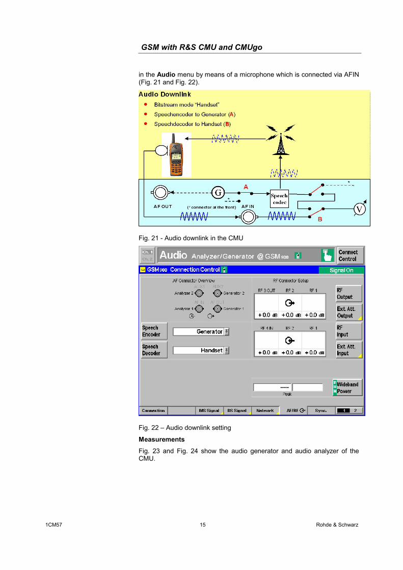
Audio downlink
Here, the audio signals generated by the CMU are sent to the mobile phone via the speech coder using RF. The mobile phone decodes the signals and outputs them on the loudspeaker. The measurement values are displayed
GSM with R&S CMU and CMUgo
1CM57 15 Rohde & Schwarz
in the Audio menu by means of a microphone which is connected via AFIN (Fig. 21 and Fig. 22).
Fig. 21 - Audio downlink in the CMU
Fig. 22 – Audio downlink setting
Measurements
Fig. 23 and Fig. 24 show the audio generator and audio analyzer of the CMU.
GSM with R&S CMU and CMUgo
1CM57 16 Rohde & Schwarz
Fig. 23 - Audio generator
Fig. 24 - Audio analyzer
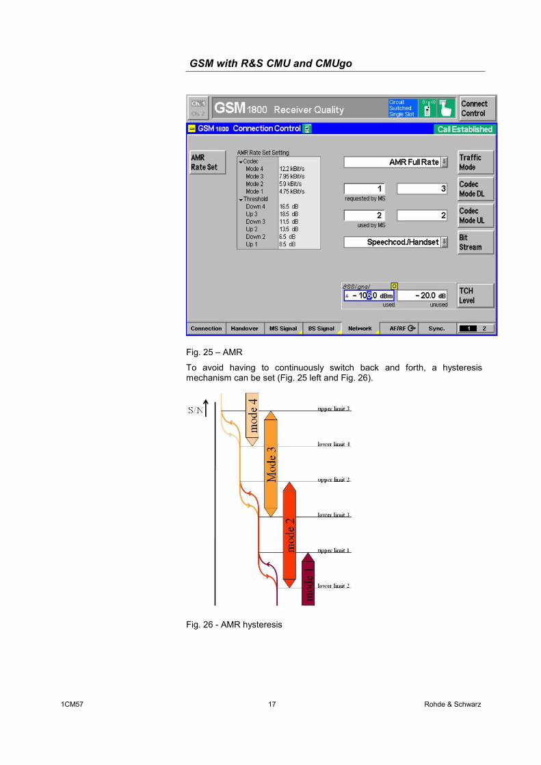
AMR
Fig. 25 shows the implementation of AMR in the CMU. The mobile phone measures the signal-to-noise ratio at a specific level and requests a codec at the base station (requested by MS).
GSM with R&S CMU and CMUgo
1CM57 17 Rohde & Schwarz
Fig. 25 – AMR
To avoid having to continuously switch back and forth, a hysteresis mechanism can be set (Fig. 25 left and Fig. 26).
Fig. 26 - AMR hysteresis
GSM with R&S CMU and CMUgo
1CM57 18 Rohde & Schwarz
4 Remote Control of the R&S CMU200 with CMUgo
Software features CMUgo offers a simple user interface for remote control of the R&S CMU200 both via a GPIB bus (IEEE488.2) and via the RS-232-C interface. CMUgo can handle all standards available on the R&S CMU200.
CMUgo includes a feature for outputting test reports. Moreover, a report of the remote-control commands with the times of the individual steps can be output, and the remote-control commands can be copied directly to the Windows clipboard for further processing.
Hardware and software requirements
Hardware requirements
• CPU: min. 300 MHz
• RAM: min. 64 Mbyte
• Monitor: SVGA with min. 800 x 600 pixels
• Hard disk: 50 Mbyte of free space
• Peripherals: National Instruments GPIB bus or RS-232-C interface, mouse
Software requirements
• Windows 98/ME/2000/XP
• CMUgo V1.51 with GSM modules V1.51 or later
Using CMUgo Please refer to the CMUgo manual [2] for information on how to connect the computer and the R&S CMU200, as well as how to install, start and operate CMUgo.
With CMUgo, the remote sequence can be output by using the Demo function. You can then create your own sequences on the basis of this sequence. CMUgo tries to perform the test sequences as quickly as possible. Since the program is structured as a sequencer (information about the previous module is not available), you may be able to save time by optimizing it further.
GSM Call Setup module In the GSM Call Setup module, all parameters that are relevant for establishing a GSM connection are set in the Circuit-Switched mode (Fig. 27). Under Network, you select the band in which the BCCH is to be generated, and which will be used for the location update. In the BCCH section, you define whether the BCCH is to be generated with AuxTX (option B95); You also set the channel and level of the BCCH here. The channel and level of the TCH that is used are selected under TCH after call setup. In addition to pure GSM, you can also select GPRS or EGPRS
GSM with R&S CMU and CMUgo
1CM57 19 Rohde & Schwarz
under Support in Network Setup . Thus, the CMU already generates a BCCH here with information about (E)GPRS so that additional (E)GPRS tests can be performed after the GSM test without carrying out another location update. The Slot mode differentiates between a single slot (conventional GSM (voice or data) and the Multislot mode (data only). If you select Single Slot, CMUgo uses the parameters under Single Slot Configuration; in the Multislot mode, an additional dialog is available (see Fig. 30). Now you have to specify the call direction: Call to mobile (MTC) or Call from mobile (MOC). Moreover, the phone can automatically be controlled via AT commands here: from mobile (voice, AT commands) sends ATD sends and the number listed under the dialed number should be to the phone; from mobile (data, AT commands) opens an additional dialog box in which you can enter any AT commands (Fig. 28). Finally, Attenuations allows you to specify the RF connector and the input and output attenuation.
Fig. 27 - Call Setup configuration
GSM with R&S CMU and CMUgo
1CM57 20 Rohde & Schwarz
Fig. 28 - Call Setup: AT commands
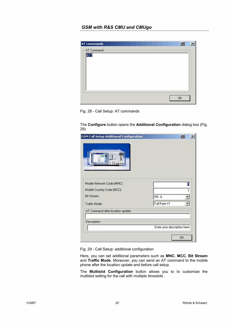
The Configure button opens the Additional Configuration dialog box (Fig. 29).
Fig. 29 - Call Setup: additional configuration
Here, you can set additional parameters such as MNC, MCC, Bit Stream and Traffic Mode. Moreover, you can send an AT command to the mobile phone after the location update and before call setup.
The Multislot Configuration button allows you to to customize the multislot setting for the call with multiple timeslots .
GSM with R&S CMU and CMUgo
1CM57 21 Rohde & Schwarz
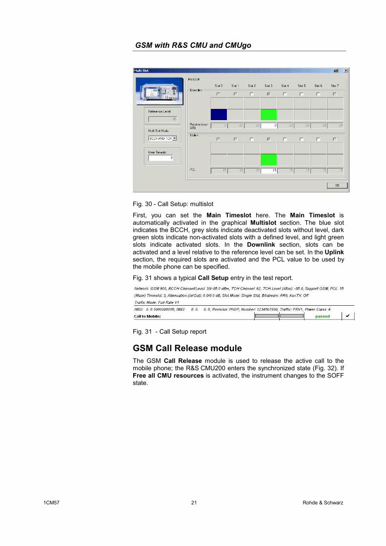
Fig. 30 - Call Setup: multislot
First, you can set the Main Timeslot here. The Main Timeslot is automatically activated in the graphical Multislot section. The blue slot indicates the BCCH, grey slots indicate deactivated slots without level, dark green slots indicate non-activated slots with a defined level, and light green slots indicate activated slots. In the Downlink section, slots can be activated and a level relative to the reference level can be set. In the Uplink section, the required slots are activated and the PCL value to be used by the mobile phone can be specified.
Fig. 31 shows a typical Call Setup entry in the test report.
Fig. 31 - Call Setup report
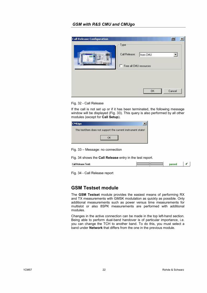
GSM Call Release module The GSM Call Release module is used to release the active call to the mobile phone; the R&S CMU200 enters the synchronized state (Fig. 32). If Free all CMU resources is activated, the instrument changes to the SOFF state.
GSM with R&S CMU and CMUgo
1CM57 22 Rohde & Schwarz
Fig. 32 - Call Release
If the call is not set up or if it has been terminated, the following message window will be displayed (Fig. 33). This query is also performed by all other modules (except for Call Setup).
Fig. 33 – Message: no connection
Fig. 34 shows the Call Release entry in the test report.
Fig. 34 - Call Release report
GSM Testset module The GSM Testset module provides the easiest means of performing RX and TX measurements with GMSK modulation as quickly as possible. Only additional measurements such as power versus time measurements for multislot or also 8SPK measurements are performed with additional modules.
Changes in the active connection can be made in the top left-hand section. Being able to perform dual-band handover is of particular importance, i.e. you can change the TCH to another band. To do this, you must select a band under Network that differs from the one in the previous module.
GSM with R&S CMU and CMUgo
1CM57 23 Rohde & Schwarz
Fig. 35 - GSM Testset
The timeslot to be measured is set using Meas Slot.
The individual measurements can be selected from the various sections. Where possible, CMUgo combines the Power and Modulation measurements to form a common measurement (designation in remote mode: POWer:MPR). To allow this, measurements must be selected under Power and Modulation. However, Origin Offset and/or IQ Imbalance must not be selected under Modulation. Additionally, graphics can be output for each measurement. If both spectrum measurements are activated (Spectrum due to Modulation and Spectrum due to Switching), the combined spectrum measurement is used (designation in remote mode: SPECtrum:MSW). Once again, the output of graphics can be activated in each case. All measurements are performed simultaneously to the extent possible in order to save time (see the Demo mode or GSM Testset in the Appendix).
Clicking the Limits button opens the dialog box shown in Fig. 36.
GSM with R&S CMU and CMUgo
1CM57 24 Rohde & Schwarz
Fig. 36 - GSM Testset: limits
The parameters for the TX measurements are set in the top left-hand section. First, the desired number of TX bursts must be set under TX Averaging (Bursts). The power limits (Power Upper Limit and Power Lower Limit), the Max Timing Error and the various parameters for the modulation measurement can also be set here. Furthermore, you can activate Decoding with guard and tail bits and choose between Average and Maximum.
The top right-hand section is reserved for RX measurements. The RX measurement limits and the number of the frames to be measured are entered in this section. Moreover, you can activate the Confidence mode.
The Spectrum section (buttom) is reserved for the two spectrum measurements. Note that it allows you to set the offsets defined by the specification and the number of bursts (No of Bursts) for each of the two measurements. Additionally, you can activate and enter four variable offsets (Var. Meas Point 1 to Var. Meas Point 4). The Slot Count parameter refers to the due to Switching measurement for multislot measurements.
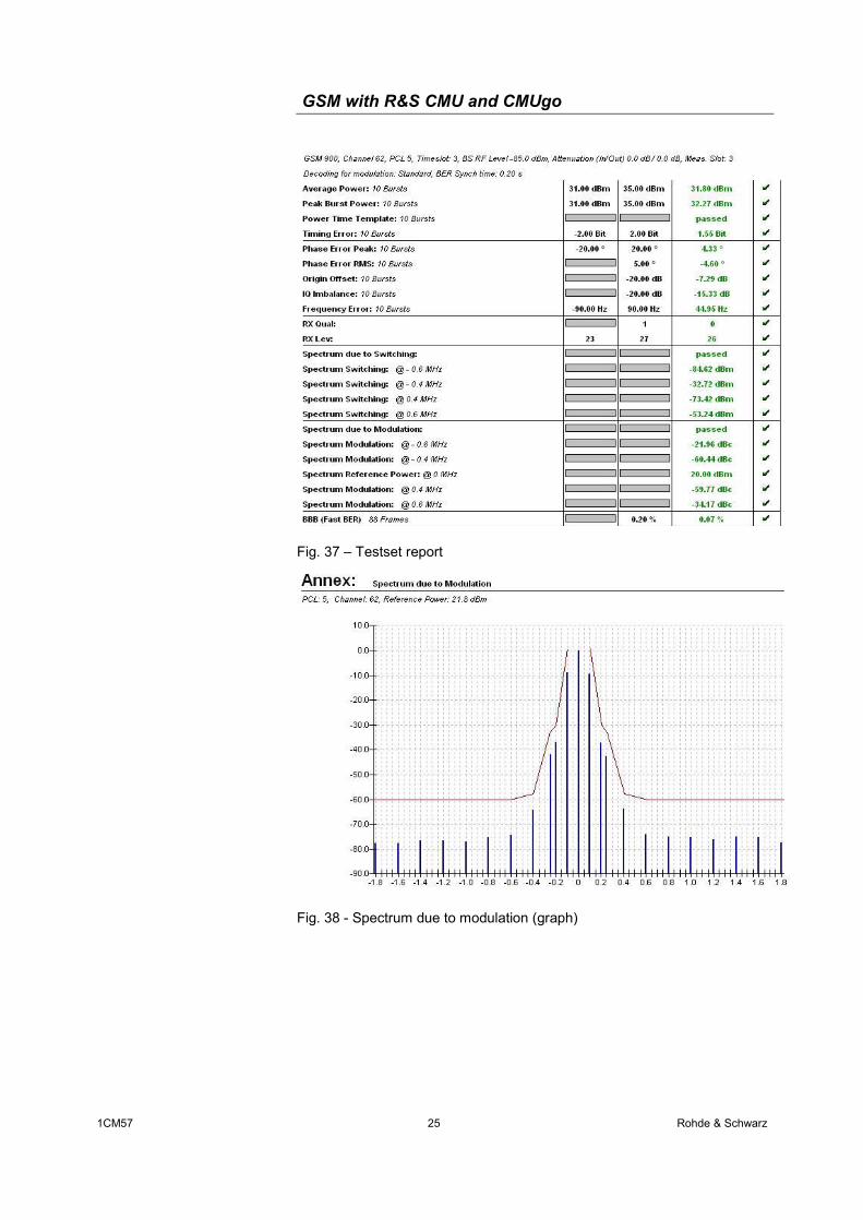
Fig. 37 , Fig. 38 and Fig. 39 show the test report entries.
GSM with R&S CMU and CMUgo
1CM57 25 Rohde & Schwarz
Fig. 37 – Testset report
Fig. 38 - Spectrum due to modulation (graph)
GSM with R&S CMU and CMUgo
1CM57 26 Rohde & Schwarz
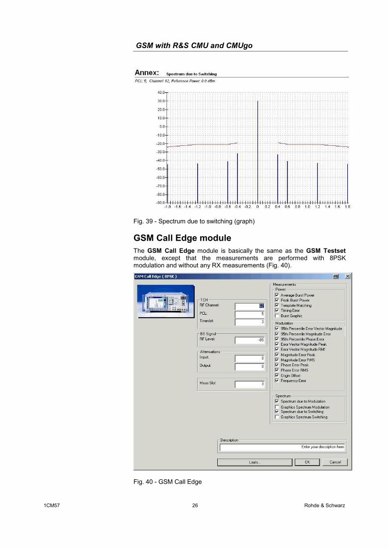
Fig. 39 - Spectrum due to switching (graph)
GSM Call Edge module The GSM Call Edge module is basically the same as the GSM Testset module, except that the measurements are performed with 8PSK modulation and without any RX measurements (Fig. 40).
Fig. 40 - GSM Call Edge
GSM with R&S CMU and CMUgo
1CM57 27 Rohde & Schwarz
The timeslot to be measured is set using Meas Slot.
The individual measurements can be selected in the various sections. Additionally, graphs can be output for each measurement. If both spectrum measurements are activated (Spectrum due to Modulation and Spectrum due to Switching), the combined spectrum measurement is used (designation in remote mode: SPECtrum:MSW). Once again, the output can be activated in each case.
Clicking the Limits button opens the dialog box shown in Fig. 41.
Fig. 41 - GSM Call Edge Limits
First, set the desired number of TX bursts under No of Bursts in the Power/Modulation section (top). The power limits (Power Upper Limit and Power Lower Limit), the Max Timing Error and the various parameters for the modulation measurement can also be set here. You can also choose between Average and Maximum.
The Spectrum section (buttom) is reserved for the two spectrum measurements. Note that it allows you to set the offsets defined by the specification and the number of bursts (No of Bursts) for each of the two measurements. Additionally, you can activate and enter four variable offsets (Var. Meas. Point 1 to Var. Meas. Point 4). The Slot Count parameter refers to the due to Switching measurement for multislot measurements.
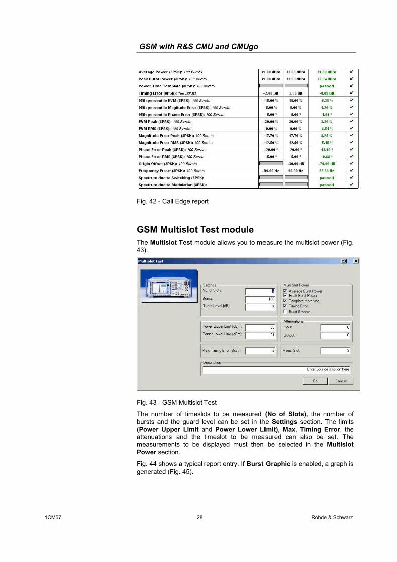
Fig. 42 shows the report; the report for spectrum measurements is identical to that for GSM Testset.
GSM with R&S CMU and CMUgo
1CM57 28 Rohde & Schwarz
Fig. 42 - Call Edge report
GSM Multislot Test module The Multislot Test module allows you to measure the multislot power (Fig. 43).
Fig. 43 - GSM Multislot Test
The number of timeslots to be measured (No of Slots), the number of bursts and the guard level can be set in the Settings section. The limits (Power Upper Limit and Power Lower Limit), Max. Timing Error, the attenuations and the timeslot to be measured can also be set. The measurements to be displayed must then be selected in the Multislot Power section.
Fig. 44 shows a typical report entry. If Burst Graphic is enabled, a graph is generated (Fig. 45).
GSM with R&S CMU and CMUgo
1CM57 29 Rohde & Schwarz
Fig. 44 – Multislot Test report (table)
Fig. 45 – Multislot Test report (graph)
GSM Audio Setting module The GSM Audio Setting module does not perform any measurements. Instead, it is simply used to enter correct settings in the uplink or downlink (Fig. 46).
GSM with R&S CMU and CMUgo
1CM57 30 Rohde & Schwarz
Fig. 46 - Audio setting
For uplink and downlink settings, see page 13.
Fig. 47 shows an entry in the test report.
Fig. 47 - Audio Setting report
The actual measurements are performed with the Audio module (seeFig. 48). Two modules are available for the two channels of the Audio option (B41).
Fig. 48 - Audio test
GSM with R&S CMU and CMUgo
1CM57 31 Rohde & Schwarz
An Audio module consists of a generator and an analyzer. The level and the frequency can be set under Generator (upper section). Moreover, you have to switch on the generator (Activate). In the middle section, you can select the measurements to be displayed. In the lower section, you can set various filters. Clicking the Limits button opens the dialog box shown in Fig. 49. Fig. 50 shows a test report entry
Fig. 49 - Audio test limits
Fig. 50 - Audio test report
GSM BER Search module The GSM BER Search module determines the sensitivity of a receiver for a specific limit value (Fig. 51). To do this, you set the channel, PCL and timeslot under TCH and set the attenuation under Attenuation. In the Measurements section, you set the BER type, the number of Frames and the limit value.
GSM with R&S CMU and CMUgo
1CM57 32 Rohde & Schwarz
Fig. 51 - BER Search
Start with a few frames using large level steps. Later approach the limit with smaller steps and more frames. Fig. 52 shows the test report entry.
Fig. 52 - BER Search report
GSM Call AMR module The GSM Call AMR allows you to test the AMR speech coder characteristics of the mobile phone (Fig. 53). To do this, set the start and stop level, step size as well as Codec mode under AMR.
Fig. 53 - Call AMR
CMUgo now reduces the level in the individual steps, and the mobile phone requests a Codec mode for each level. This mode is displayed in a table in the report. To include the hysteresis loops, the level is then increased back up to the initial state.
GSM with R&S CMU and CMUgo
1CM57 33 Rohde & Schwarz
Fig. 54 – AMR report
GSM Call Change Multislot module The GSM Call Change Multislot module is used to change call parameters in the multislot mode (Fig. 55). The parameters correspond to those in Fehler! Verweisquelle konnte nicht gefunden werden. (see "GSM Call Setup module").
Fig. 55 - Call Change Multislot
Fig. 56 shows the test report entry.
Fig. 56 - Call Change Multislot report
GSM Channel Scan module The GSM Channel Scan module is used to perform power measurements across multiple channels (Fig. 57). To do this, you need to set the following parameters in the TCH section: Start Channel, Stop Channel, PCL and
GSM with R&S CMU and CMUgo
1CM57 34 Rohde & Schwarz
Timeslot. You also need to set the level and attenuation values. The CMU now performs the power measurements selected under Measurements on the Meas. Slot using the number of bursts.
Fig. 57 - Channel Scan
the channels with the maximum and minimum power (Fig. 58) and a graph of all values are output (Fig. 59).
Fig. 58 - Channel Scan report
Fig. 59 - Channel Scan graph
GSM with R&S CMU and CMUgo
1CM57 35 Rohde & Schwarz
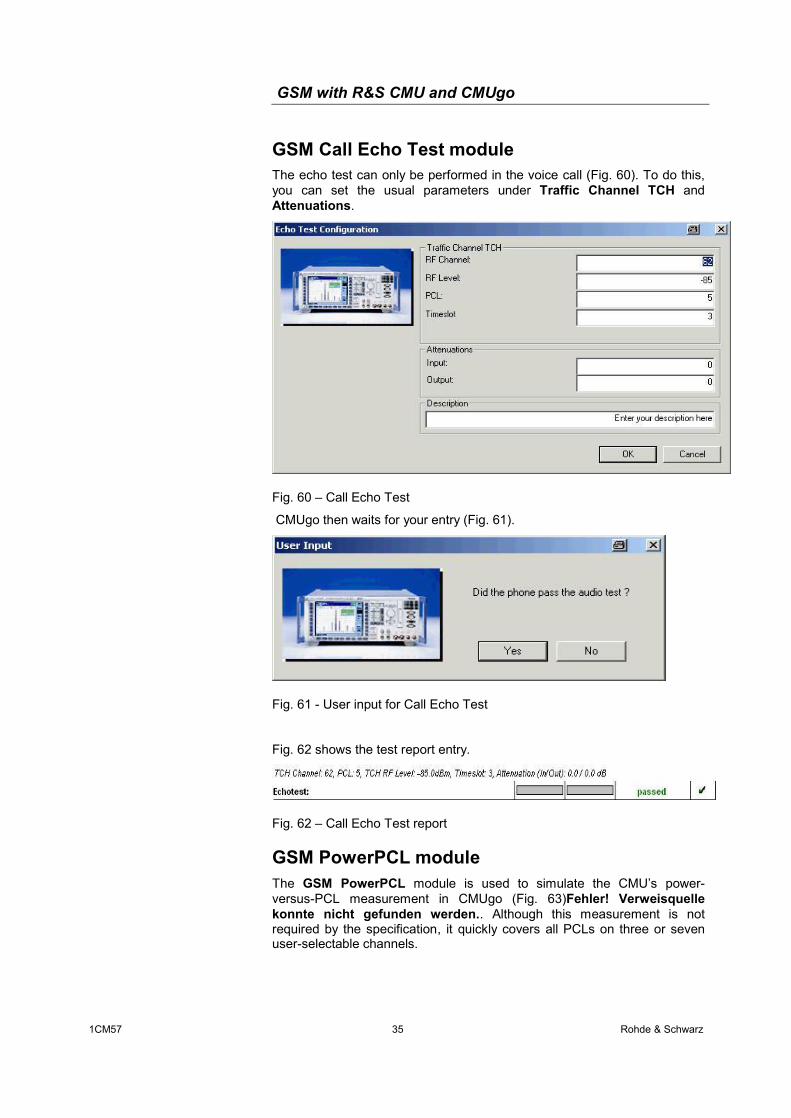
GSM Call Echo Test module The echo test can only be performed in the voice call (Fig. 60). To do this, you can set the usual parameters under Traffic Channel TCH and Attenuations.
Fig. 60 – Call Echo Test
CMUgo then waits for your entry (Fig. 61).
Fig. 61 - User input for Call Echo Test
Fig. 62 shows the test report entry.
Fig. 62 – Call Echo Test report
GSM PowerPCL module The GSM PowerPCL module is used to simulate the CMU’s power- versus-PCL measurement in CMUgo (Fig. 63)Fehler! Verweisquelle konnte nicht gefunden werden.. Although this measurement is not required by the specification, it quickly covers all PCLs on three or seven user-selectable channels.
GSM with R&S CMU and CMUgo
1CM57 36 Rohde & Schwarz
Fig. 63 – PowerPCL
Fig. 64 – PowerPCL report
Fig. 1 – PowerPCL graph
GSM with R&S CMU and CMUgo
1CM57 37 Rohde & Schwarz
5 Appendix
List of Figures Fig. 1 - Downlink on two channels without option B95 .......................................3 Fig. 2 – CMU setup for BS signal without option B95.........................................4 Fig. 3 - Downlink on the same channel without option B95................................4 Fig. 4 - Downlink with option B95 .......................................................................4 Fig. 5 – CMU setup for BS signal with option B95..............................................5 Fig. 6 – Analyzer mode.......................................................................................6 Fig. 7 – Default state of the CMU .......................................................................6 Fig. 8 - CMU in the synchronized state ..............................................................7 Fig. 9– (E)GPRS states in the CMU...................................................................7 Fig. 10 – Overview menu....................................................................................8 Fig. 11 - Power vs time measurement................................................................9 Fig. 12 – PowerPCL ...........................................................................................9 Fig. 13 – Modulation .........................................................................................10 Fig. 14 - Spectrum due to modulation ..............................................................11 Fig. 15 - Spectrum due to switching .................................................................11 Fig. 16 – Combined spectrum measurement ...................................................12 Fig. 17 - Receiver quality..................................................................................13 Fig. 18 - Audio setting: Bit Stream....................................................................13 Fig. 19 - Audio uplink in the CMU.....................................................................14 Fig. 20 - Audio uplink setting ............................................................................14 Fig. 21 - Audio downlink in the CMU ................................................................15 Fig. 22 – Audio downlink setting.......................................................................15 Fig. 23 - Audio generator..................................................................................16 Fig. 24 - Audio analyzer....................................................................................16 Fig. 25 – AMR...................................................................................................17 Fig. 26 - AMR hysteresis ..................................................................................17 Fig. 27 - Call Setup configuration .....................................................................19 Fig. 28 - Call Setup: AT commands .................................................................20 Fig. 29 - Call Setup: additional configuration....................................................20 Fig. 30 - Call Setup: multislot............................................................................21 Fig. 31 - Call Setup report ...............................................................................21 Fig. 32 - Call Release .......................................................................................22 Fig. 33 – Message: no connection....................................................................22
Power measurement (singleshot, 10 bursts). CONF:POW:CONT:REP SING,NONE,NONE
CONF:POW:CONT ARR,10
READ:POW?
FETC:ARR:POW?
Modulation measurement (singleshot, 10 bursts, standard decoding): CONF:MOD:XPER:CONT:REP SING,NONE,NONE
CONF:MOD:XPER:CONT ARR,10
CONF:MOD:XPER:TIME:DEC STAN
READ:MOD:XPER?
FETC:ARR:MOD:XPER?
Spectrum measurement (modulation: points 4 and 5 ON, 10 bursts, singleshot; switching: points 1 and 2 ON, 10 bursts, combined measurement): CONF:SPEC:MOD:CONT:MPO1:ENAB OFF
CONF:SPEC:MOD:CONT:MPO2:ENAB OFF
CONF:SPEC:MOD:CONT:MPO3:ENAB OFF
CONF:SPEC:MOD:CONT:MPO4:ENAB ON
CONF:SPEC:MOD:CONT:MPO5:ENAB ON
CONF:SPEC:MOD:CONT:MPO6:ENAB OFF
CONF:SPEC:MOD:CONT:MPO7:ENAB OFF
CONF:SPEC:MOD:CONT:MPO8:ENAB OFF
GSM with R&S CMU and CMUgo
1CM57 41 Rohde & Schwarz
CONF:SPEC:MOD:CONT:MPO9:ENAB OFF
CONF:SPEC:MOD:CONT:MPO10:ENAB OFF
CONF:SPEC:MOD:CONT:MPO11:ENAB OFF
CONF:SPEC:MOD:CONT ARR,10
CONF:SPEC:MOD:CONT:REP SING,NONE,NONE
CONF:SPEC:MSW:CONT ARR
CONF:SPEC:MSW:CONT:REP SING,NONE,NONE
CONF:SPEC:SWIT:CONT:MPO1:ENAB ON
CONF:SPEC:SWIT:CONT:MPO2:ENAB ON
CONF:SPEC:SWIT:CONT:MPO3:ENAB OFF
CONF:SPEC:SWIT:CONT:MPO4:ENAB OFF
CONF:SPEC:SWIT:CONT ARR,10
CONF:SPEC:SWIT:CONT:REP SING,NONE,NONE
CONF:SPEC:SWIT:NOSL 1
INIT:SPEC:MSW
FETC:SPEC:MSW?
FETC:ARR:SPEC:MSW?
GSM Call Edge
The spectrum measurements are identical to those for GSM testset.
Status query, attenuation (0 dB), meas. slot (3): SENS:SIGN:STAT?
Setting of multislot and channel: PROC:SIGN:MSL:SCON 3,OFF,OFF,OFF,ON,ON,OFF,OFF,OFF,0.0,0.0,0.0,0.0,0.0,0.0,0.0,0.0,OFF,OFF,OFF,ON,OFF,OFF,OFF,OFF,3,3,3,3,3,3,3,3
This Application Note and the supplied programs may only be used subject to observance of the conditions of use set forth in the download area of the Rohde & Schwarz website.