12
RELAY SUPPLY GSM-RELAY REMOTE CONTROL UNIT GSM-RELAY MANUAL V5.0 From 2016 RELAY SUPPLY http://relaysupply.com
RELAY SUPPLY GSM-RELAY REMOTE CONTROL UNIT
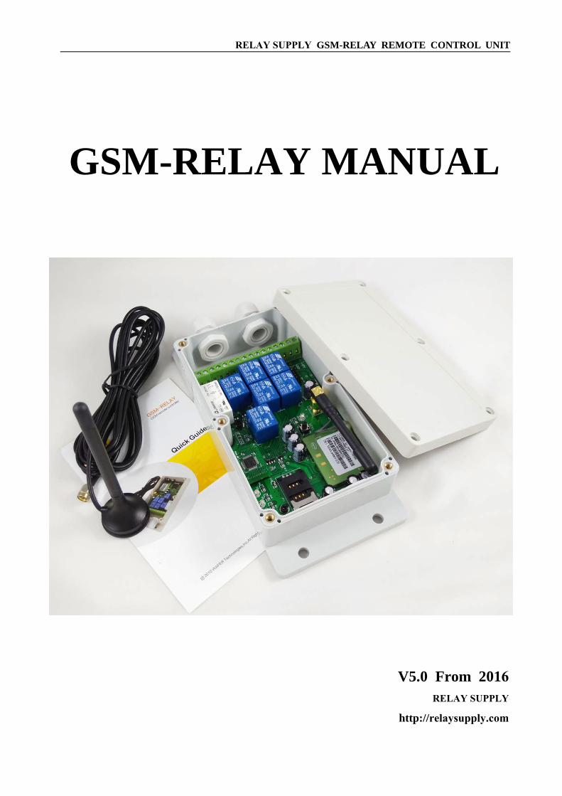
GSM-RELAY MANUAL
V5.0 From 2016
RELAY SUPPLY
http://relaysupply.com

RELAY SUPPLY GSM-RELAY REMOTE CONTROL UNIT
http://relaysupply.com
GSM-RELAY OPERATING INSTRUCTIONS
PRODUCT DESCRIPTION
The GSM-RELAY is an electronic device with an on-board GSM modem. The purpose of this device is to do the real time and interactive GSM remote control by means of a GSM phone.
CONNECTOR DESCRIPTION
ADVANTAGES OF THE GSM-RELAY
ˇ 7 channels 230V 10A 50Hz relay contacts.
ˇ No call charges to operate via phone calling.
ˇ Any in the world can phone or send an SMS to operate the device.ˇ Relay can operate almost every appliance (might need to cut some wires!).ˇ Password protection and remote password change.
ˇ Two relay modes for first relay: latching and momentary.ˇ Caller ID confirmation for security.
ˇ Can be operated from anywhere.
ˇ All relays can be controlled via SMS in a latching or timed mode (i.e. 5 seconds).ˇ Easy programming in minutes with your phone or PC software.
ˇ Access Control List can be enabled or disabled if security is not needed. ˇ Quick & easy number programming with SMS or on board teaching button.
ˇ Can disable SMS replies to save on cost.ˇ Support for customized commands for easy understanding.ˇ Support for optional Wifi-plug for remote parameters program.ˇ Support for device operation history LOG check.
RELAY SUPPLY GSM-RELAY REMOTE CONTROL UNIT
http://relaysupply.com
INSTALLATION
To install the GSM-RELAY, you need to power on the board with AC/DC 9V-12V. and also
connect the relay output according to your project. The relay contacts can stand 230V 10A
maximum, this is enough for its operation but don't try to switch higher voltages or currents.
You should install the GSM-RELAY in a place where there is GSM signal coming from the
operator you want to use. Check it with a phone before proceeding with the installation. If you
need to install the device in a place with little signal, you may consider using an external antenna
that we may supply as an option to be purchased separately with 3m cable.
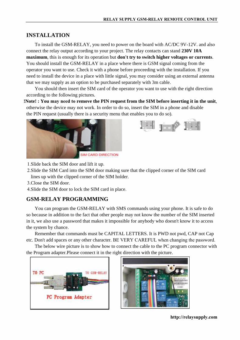
You should then insert the SIM card of the operator you want to use with the right direction
according to the following pictures.
!Note! : You may need to remove the PIN request from the SIM before inserting it in the unit,
otherwise the device may not work. In order to do so, insert the SIM in a phone and disable
the PIN request (usually there is a security menu that enables you to do so).
GSM-RELAY PROGRAMMING
You can program the GSM-RELAY with SMS commands using your phone. It is safe to do
so because in addition to the fact that other people may not know the number of the SIM inserted
in it, we also use a password that makes it impossible for anybody who doesn't know it to access
the system by chance.
Remember that commands must be CAPITAL LETTERS. It is PWD not pwd, CAP not Cap
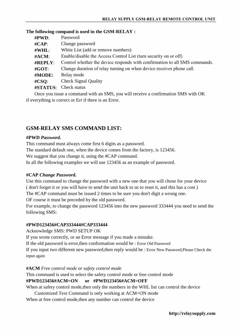
etc. Don't add spaces or any other character. BE VERY CAREFUL when changing the password.The below wire picture is to show how to connect the cable to the PC program connector with
the Program adapter.Please connect it in the right direction with the picture.
1.Slide back the SIM door and lift it up.2.Slide the SIM Card into the SIM door making sure that the clipped corner of the SIM card
lines up with the clipped corner of the SIM holder.3.Close the SIM door.4.Slide the SIM door to lock the SIM card in place.
RELAY SUPPLY GSM-RELAY REMOTE CONTROL UNIT
http://relaysupply.com
The following compand is used in the GSM-RELAY :
#PWD:
#CAP:
#WHL:
#ACM:
#REPLY:
#GOT:
#MODE:
#CSQ:
#STATUS:
Password
Change password
White List (add or remove numbers)
Enable/disable the Access Control List (turn security on or off)Control whether the device responds with confirmation to all SMS commands.Change duration of relay turning on when device receives phone call. Relay mode
Check Signal Quality
Check status
Once you issue a command with an SMS, you will receive a confirmation SMS with OK
if everything is correct or Err if there is an Error.
GSM-RELAY SMS COMMAND LIST:
#PWD Password.
This command must always come first 6 digits as a password.
The standard default one, when the device comes from the factory, is 123456.
We suggest that you change it, using the #CAP command.
In all the following examples we will use 123456 as an example of password.
#CAP Change Password.
Use this command to change the password with a new one that you will chose for your device
( don't forget it or you will have to send the unit back to us to reset it, and this has a cost )
The #CAP command must be issued 2 times to be sure you don't digit a wrong one.
OF course it must be preceded by the old password.
For example, to change the password 123456 into the new password 333444 you need to send the
following SMS:
#PWD123456#CAP333444#CAP333444
Acknowledge SMS: PWD SETUP OK
If you wrote correctly, or an Error message if you made a mistake.
If the old password is error,then conformation would be : Error Old Password
If you input two different new password,then reply would be : Error New Password,Please Check the
input again
#ACM Free control mode or safety control mode
This command is used to select the safety control mode or free control mode
#PWD123456#ACM=ON or #PWD123456#ACM=OFF
When at safety control mode,then only the numbers in the WHL list can control the device
Customized Text Command is only working at ACM=ON mode
When at free control mode,then any number can control the device
RELAY SUPPLY GSM-RELAY REMOTE CONTROL UNIT
http://www.waferstar.com
#REPLY SMS reply enable or disable for relay output control command
This command is used to save the cost for SMS reply when no need the SMS reply back
#PWD123456#REPLY=ON or #PWD123456#REPLY=OFF
When REPLY=OFF,then any relay output control text command would no confirmed SMS reply
from controller,including the OUT, RLY and the Customized Text Command
#WHL White List.
This is the command that you will use most. It is used to add or remove numbers that are enabled
to control the relay sets into the White List. You can add up to 200 numbers in the list. Every
position must be indicated in the command and we advise you to keep a list written somewhere to
know which numbers are in and in which position.
• To add a number with SMS, the syntax of the command is the following:
#PWD123456#WHL01=61143815
Acknowledge would be : WHL01 SET TO 61143815 OK
Where 01 is the position in the list and 61143815 is the number enabled.
Please note that it is possible to program up to a maximum of 18 digits for a number. If it has
more digits you should use the rightmost ones. For example, if your number is 33446665555 you
should program 3446665555. If your number appears as +85261143815 you should not program
the country code (+852). If your number has only 17 digits or less, it is not a problem. The
important thing is that you don't exceed 18 digits.
• To add a new number,you also can use the fast teaching button
(only from WHL01 to WHL10)
Press the button KEY1 for around 2 to 3 second and then the LED D1 would be lighting,and then
you can use the phone to call the device number and then device would reject the calling and the
LED D1 would flash one or two times,then the number would be saved. If you need to continue to
program,then just use another phone to call the device. If you don’t need to program more ,then
just press the KEY1 button again to QUIT the teaching process,then the LED D1 would be OFF.
Then you can use the numbers just programmed into the device to control the device.
(Fast Button program only support the program from WHL01 to WHL10,if it is full,then after
you press the teach button,the LED would flash sometimes,and Quit the process automatically)
• To check which is the number in a place of the list:
#PWD123456#WHL01?
Acknowledge : WHL01 IS 61143815 OK
• To erase a number:
#PWD123456#WHL01=0000000
(or you can write over it another number you wish to add)
Acknowledge : WHL01 SET TO 00000000
List All numbers in the List
#PWD123456#WHL=ALL? (PC)
Acknowledge :
WHL01 IS XXX
WHL03 IS XXX
WHL08 IS XXX
RELAY SUPPLY GSM-RELAY REMOTE CONTROL UNIT
http://relaysupply.com
……
#QUERY White List.
If you are not sure a number in the position of the device,you can use the SMS
#PWD123456#QUERY=132324242
The device would answer the SMS with: QUERY RESULT: 132324242 AT WHL121
Or QUERY RESULT: 132324242 NOT EXIT
#GOT Relay working output delay time.
This command is useful in case you need to keep the Relay output working longer. The standard
time is 0,3 seconds (300 ms). You can change it with the GOT command.
• The syntax of the command is the following:
#PWD123456#GOT500 (PC$PHONE)(Only for NO.1 Relay)
Acknowledge: DELAY TIME SET TO 0500MS
With the above command the delay time has been set to 500 ms (0,5 seconds).
• You can check what the current relay output delay time is with the command
#PWD123456#GOT? (PC$PHONE) (Only for NO.1 Relay)
Acknowledge: DELAY TIME IS 0500 MS
Also you can change the Timer Ratio from millisecond to Second or Minute
#PWD123456#TIMER-DELAY-AT-MILLISECOND;
#PWD123456#TIMER-DELAY-AT-SECOND;
#PWD123456#TIMER-DELAY-AT-MINUTE;
#MODE Relay Operation Mode SETUP (PC$PHONE) (Only for NO.1 Relay)
#PWD123456#MODE0
Acknowledge: RELAY SET TO MODE0
#PWD123456#MODE1
Acknowledge: RELAY SET TO MODE1
If setup to MODE0,that is Momentary pulse mode, when you call the SIM card number , device will toggle the
relay and delay a GOT timer ,then the relay will back the previous status.
If setup to MODE1,that is Ratchet relay mode,when you call the SIM card number,device will switch to the
other status ON or OFF ,and when you call again ,it will switch the status again.
#PWD123456#MODE? (Check the RELAY MODE Status)
Acknowledge: RELAY IS MODE0 or RELAY IS MODE1
#OUT Relay output control
(1)ON the relay output contact
#PWD123456#OUTX=ON (PC$PHONE)
Where X is the number of the relay in the list (X is from 1 to 7)
Acknowledge: OUTX ON OK
(2)OFF the relay output contact
#PWD123456#OUTX=OFF (PC$PHONE)
Where X is the number of the relay in the list (X is from 1 to 7)
Acknowledge: OUTX OFF OK

RELAY SUPPLY GSM-RELAY REMOTE CONTROL UNIT
http://relaysupply.com
(3)ALL the relay control at the same time
#PWD123456#OUT=1101011 (PC$PHONE)
Where the number is 1 or 0 to ON or OFF the relay.
Acknowledge: #PWD123456#OUT=1101011 OK
(3)Check the relay status
#PWD123456#OUT? (PC$PHONE)
Check the status of all the relay
Acknowledge: OUT 1110000 (the Number “1” means RELAY ON and “0” means RELAY OFF)
#RLY Temporary latching of output relays (Only Can control from RELAY2 to RELAY7)
This command allows the temporarily switch on the Relays for up to 65,000 seconds and receive
confirmation SMS text alerts when the Relays switch on and off
To activate relay 1 for 60 seconds you would send the following SMS text message to the unit
#PWD123456#RLY2=0005 (From RLY2 to RLY7)
Where 2 indicates the relay number and 0005 is the time in seconds and should be entered in a 5
digit format as shown
The administrator number will receive the following confirmation text message from the unit
OUT2 Timer Start ON for 5 Minutes OK
when the relay 1 switches on, the administrator number will receiver the following message when
the relay switches off
OUT2 Timer OFF OK
Note: Relay1 cann’t be controlled by the RLY command, if you want to control the Relay1 at a temporary
latching timer, you can setup a suitable GOT timer,and use the phone calling to control directly.
#CSQ Check GSM signal quality. (PC$PHONE)
This command is useful to see what is the GSM network signal level your GSM-RELAY is
receiving. It ranges from 0 to 32 (if it is 0 we doubt it will ever answer...). You should have a
signal above 12 to be sure of being able to control the relay sets in any condition. Better if above
16. You should add an external antenna if this is not the case, or eventually even change operator
with another that serves your area better.
#PWD123456#CSQ?
Acknowledge: CSQ IS 23
#PWD123456#STATUS?
Acknowledge: ACM=ON,REPLY=ON,RELAY=MODE0,GOT=3S, CSQ=20,OUT=0000000
Customized Text Command to control the OUTPUT:
#PWD123456#OUT1-ON-TEXT:XXXX
#PWD123456#OUT1-OFF-TEXT:XXXX
#PWD123456#OUT1-ON-REPLY-TEXT:XXXX
#PWD123456#OUT1-OFF-REPLY-TEXT:XXXX

RELAY SUPPLY GSM-RELAY REMOTE CONTROL UNIT
http://relaysupply.com
#PWD123456#OUT2-ON-TEXT:XXXX
#PWD123456#OUT2-OFF-TEXT:XXXX
#PWD123456#OUT2-ON-REPLY-TEXT:XXXX
#PWD123456#OUT2-OFF-REPLY-TEXT:XXXX
………
Then from OUT1 to OUT7, use the similar command to do the TEXT Command customized.
#PWD123456#RLY1-TEXT:XXXX
#PWD123456#RLY1-REPLY-TEXT:XXXX
#PWD123456#RLY2-TEXT:XXXX
#PWD123456#RLY2-REPLY-TEXT:XXXX
………
Then from RLY1 to RLY7, use the similar command to do the TEXT Command customized.
Text Command QUERY:
#PWD123456#OUT-TEXT? (only for PC command)
REPLY:
OUT1-ON:WSD1ON
OUT1-OFFWSD1OFF
OUT2-ON:WSD2ON
OUT2-OFFWSD2OFF
OUT3-ON:WSD3ON
OUT3-OFFWSD3OFF
OUT4-ON:WSD4ON
OUT4-OFFWSD4OFF
OUT5-ON:WSD5ON
OUT5-OFFWSD5OFF
OUT6-ON:WSD6ON
OUT6-OFFWSD6OFF
OUT7-ON:WSD7ON
OUT7-OFFWSD7OFF
#PWD123456#OUT-REPLY-TEXT? (only for PC command)
OUT1-ON-REPLY-TEXT:WSD1ON OK
OUT1-OFF-REPLY-TEXT:WSD1OFF OK
OUT2-ON-REPLY-TEXT:WSD2ON OK
OUT2-OFF-REPLY-TEXT:WSD2OFF OK
OUT3-ON-REPLY-TEXT:WSD3ON OK
OUT3-OFF-REPLY-TEXT:WSD3OFF OK
OUT4-ON-REPLY-TEXT:WSD4ON OK
OUT4-OFF-REPLY-TEXT:WSD4OFF OK
OUT5-ON-REPLY-TEXT:WSD5ON OK
OUT5-OFF-REPLY-TEXT:WSD5OFF OK
OUT6-ON-REPLY-TEXT:WSD6ON OK
OUT6-OFF-REPLY-TEXT:WSD6OFF OK
RELAY SUPPLY GSM-RELAY REMOTE CONTROL UNIT
http://relaysupply.com
OUT7-ON-REPLY-TEXT:WSD7ON OK
OUT7-OFF-REPLY-TEXT:WSD7OFF OK
PWD123456#RLY-TEXT? (only for PC command)
RLY1-TEXT:WSDRLY1
RLY1-REPLY-TEXT:WSDRLY1 OK
RLY2-TEXT:WSDRLY2
RLY2-REPLY-TEXT:WSDRLY2 OK
RLY3-TEXT:WSDRLY3
RLY3-REPLY-TEXT:WSDRLY3 OK
RLY4-TEXT:WSDRLY4
RLY4-REPLY-TEXT:WSDRLY4 OK
RLY5-TEXT:WSDRLY5
RLY5-REPLY-TEXT:WSDRLY5 OK
RLY6-TEXT:WSDRLY6
RLY6-REPLY-TEXT:WSDRLY6 OK
RLY7-TEXT:WSDRLY7
RLY7-REPLY-TEXT:WSDRLY7 OK
Data Log Check (Only for PC Connnecting)
With this command,we can check the inside config and control Log information
#PWD123456#LOG=ALL?
Reply would be as following data:
………
LOGS015:201501072143:18017370819:PHONE
LOGS016:201501072143:18017370819:PHONE
LOGS017:201501072141:18017370819:PHONE
LOGS018:201501071937:+8613564121668:WSDRLY2=13
LOGS019:201501071937:+8613564121668:WSDRLY6=6
LOGS020:201501071937:+8613564121668:RLY3=8……….
……….
If use this command not properly, that SIM card will not send the SMS successfully
Program software:
Please download from the product link: http://www.waferstar.com/en/GSM-RELAY.html
On board Reset:
Press and hold the button for around 10 second,then the board would reseted,and the following
RELAY SUPPLY GSM-RELAY REMOTE CONTROL UNIT
http://relaysupply.com
data would be reseted to:
Password:123456,
From WHL01 to WHL10 would be cleared
ACM=OFF, REPLY=ON, MODE=MODE0, GOT=3S, Relay Output=0000000
Troubleshooting
No LED is on after power up
· Check the power supply.
· Check the wires is connected well.
GSM LED D6 is not flash slowly
(GSM LED normally flash quickly when power off and when it connected to GSM net ,then
would flash around two seconds per time).
· Check your ordered device if that is the proper GSM BAND to your country.
(Some country is QUAD BAND , some others is DUAL BAND, please check our wiki.
· Check the SIM card is properly inserted.
· Check the PIN.(Normally don’t need to check, if SIM card can work with your mobile phone.)
· Check the antenna connection is fitted well.
· GSM Signal is not good and cann’t register to GSM,try to move to another place to test.
· If still cann’t registered to the GSM net, try to contact Relay Supply to get technical support.· When LED D6 is flashing slowly,try to call the SIM card,the calling status would be in busy.
MCU LED D4 is not flash slowly
· MCU is not working properly,Check the system power
No Relay working tone can be heard when phone calling the device
· Check if your Control number is already setup into the device.
· GSM-RELAY is not initialized properly upon start (approx. 10s after power up).
· If the GOT timer is setup to a very short timer ( normally should be more than 500ms )
GSM-RELAY does not communicate with PC
· Check the serial cable connection.
· Check the COM number setting on PC.
· Check if you select the “ New Line ” selection box
· Check if you input the right instruction line and that should be all use the Capital word,
· Check the COM parameters (9600 bps, 8N1).
· An incoming call is ringing on GSM-RELAY
· An incoming SMS message is on processing by GSM-RELAY
RELAY SUPPLY GSM-RELAY REMOTE CONTROL UNIT
http://relaysupply.com
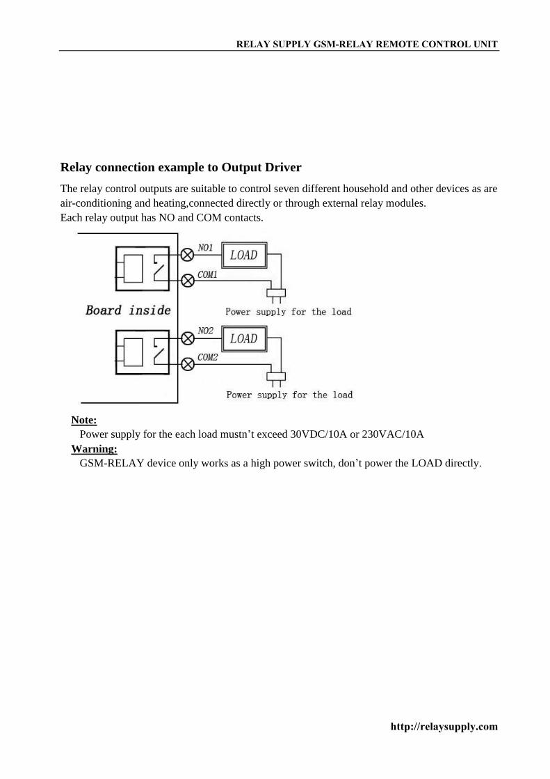
Relay connection example to Output Driver
The relay control outputs are suitable to control seven different household and other devices as are
air-conditioning and heating,connected directly or through external relay modules.
Each relay output has NO and COM contacts.
Note:
Power supply for the each load mustn’t exceed 30VDC/10A or 230VAC/10A
Warning:
GSM-RELAY device only works as a high power switch, don’t power the LOAD directly.

RELAY SUPPLY GSM-RELAY REMOTE CONTROL UNIT
http://relaysupply.com
For additional questions or information, please contact Relay Supply:
Email: [email protected]: http://relaysupply.com


