37
i DIVISION OF DESIGN Office of Pavement Design Pavement Design & Analysis Branch Guide for Design and Construction of New Jointed Plain Concrete Pavements (JPCPs) January 9, 2008
i
DIVISION OF DESIGN Office of Pavement Design
Pavement Design & Analysis Branch
Guide for Design and Construction of New Jointed Plain Concrete Pavements
(JPCPs)
January 9, 2008
ii
TABLE OF CONTENTS 1.0 PURPOSE OF THIS GUIDE……..………………………………...…..……..… 1 2.0 SYSTEM DESCRIPTION…...…………..……………………………….…....… 1 3.0 SELECTING RIGID PAVEMENT………….....……………….....…………..... 1 4.0 COMPONENTS OF JPCP……………………………………………...…….…. 2
4.1 Concrete……………………………………………..……………………… 2 4.2 Joints………..……..…………………………………………………..……. 3
4.2.1 Joint Construction…………………...…………..…..……..…..… 3 4.2.2 Joint Types……….……………………………….……….....…… 3 4.2.2.1 Transverse Joints……….………………..……….……….....…… 3 4.2.2.2 Longitudinal Joints…….….……………..……….……….....…… 5
4.3 Other Joints………………………………………………………………… 5 4.3.1 Isolation Joint………..…………..……………………………….. 5 4.3.2 Construction Joint..……………..……………………………….. 6
4.4 Tie Bars……………………...……………………………………………… 6 4.5 Load Transfer….…...……………………………………………………… 7
4.5.1 Dowel Bars ………………………..……………..……………….. 7 4.5.2 Aggregate Interlock…………....…...……………….….……..…. 9 4.5.3 Stabilized Base………………..……………………………..…… 10
4.6 Subgrade, Subbase and Base……………………………………………… 10 4.6.1 Subgrade…………..……………..……………………………….. 10 4.6.2 Subbase Layer…………….……..……………………………….. 11 4.6.3 Base Layer………………………..………………………………. 11
5.0 DESIGN OF JPCP……………………………….…….…………...…..…...….... 12
5.1 Design Life…………..……………………….………..………….……..…. 12 5.2 Pavement Performance Factors….…………………………….....….…… 13 5.3 Design Thicknesses…………………..…….……………….…..…….……. 13
6.0 JPCP DESIGN - THEN and NOW……….……………………....………….…. 13 7.0 SPECIALTY CASES……………….……………….……...….…..………….…. 15
7.1 Widening…………………....…………………………………………….. 15 7.2 Widened Lanes with HMA Shoulder……..…………………………….. 15 7.3 Narrow Shoulders…………………….…………………….…………..... 15 7.4 Transition Situation………………………....………………...……..…... 15 7.5 Joints at Intersection…………………….……..……..………………….. 16 7.6 Concrete Barrier in Concrete Paved Median with Joint……..……….. 16 7.7 Concrete Pavement Over Drainage Culverts…………….…………….. 17
8.0 DETAILING…………………………………………...……..…….…………….. 17 9.0 CONSTRUCTION of JPCP.……….….………………………………….……... 18
iii
9.1 Subgrade, Subbase and Base Preparation………………….…….…..….. 18 9.1.1 Subgrade Preparation……………………….…………..……….. 18 9.1.2 Subbase Layer Preparation….…………….……………….…… 19 9.1.3 Base Layer Preparation………………………………….………. 19 9.1.3.1 Hot Mix Asphalt Type A (HMA-A)……….…………….………. 19 9.1.3.2 Lean Concrete Base (LCB)………….…….…………….….……. 20 9.1.3.3 Asphalt Treated Permeable Base (ATPB)…..………….………. 20 9.1.3.4 Aggregate Base (AB)………………………….………….………. 21
9.2 Steel Placement………………………..…………………..….…….…..….. 21 9.2.1 Tie Bar Placement……………..…….…….…………….….……. 21 9.2.1.1 Drill and Bond Method……….…….…….……………..….……. 22 9.2.1.2 Threaded Splice Coupler Method….….…….…………………... 22 9.2.1.3 Tie Bar Basket……………………………………………….……. 22 9.2.1.4 Insertion Method……….………………………………………… 22 9.2.2 Dowel Bar Placement………….…….…….……………..………. 22 9.2.3 Bar Reinforcement Placement…………….…………….………. 24
9.3 Concrete Placement…………………………………….…..……..…...…... 24 10.0 MAKING JOINTS.…………………...….………………………...………….…. 24
10.1 Saw Cutting….…………..……….….………………….…..……..…...…... 24 10.2 Joint Sealing..………….…………….………………….…..……..…...…... 25
11.0 SURFACE TEXTURING.…………………...…………………...……………… 28 12.0 STANDARD PLANS AND STANDARD SPECIAL PROVISIONS (SSPs)…. 29
12.1 Standard Plans……………………………………………..…………….… 30 12.2 Standard Special Provisions (SSPs)……………………...……………..… 31
13.0 COST ESTIMATION………………………………….….…………….……….. 32 14.0 MEASUREMENT AND PAYMENT………………………………….………... 32 15.0 REFERENCES……….…………………….……….…………………………..... 32 16.0 QUESTIONS AND COMMENTS………………….…….……………………... 33

Guide for Design and Construction of New Jointed Plain Concrete Pavements. January 9, 2008. 1
1.0 PURPOSE OF THIS GUIDE The long-term performance of a newly constructed concrete (rigid) pavement relies on good construction practices and proper pavement design and selection of materials. Premature failures of rigid pavements are often the result of poor construction practices or improper application of design principles and materials. This Guide not only discusses related topics in the design and construction of new jointed plain concrete pavements (JPCPs), but also presents some tips in using the current pavement related Standard Plans and corresponding Special Provisions that a pavement engineer will need to design and build a long lasting concrete pavement. It is recommended that a set of Standard Plans be available for referencing when reading this Guide. The 2006 P-Series Standard Plans cover most aspects of new JPCPs. The Designer should reference the appropriate pavement related Standard Plans, and incorporate them into the contract documents where needed. This Guide does not discuss rehabilitation methods of existing JPCPs, which can be found in a separate guide which can be found on the Department’s Pavement Engineering website. The Pavement Engineering website has technical pavement related information such as excerpts from various manuals, technical advisories, design information bulletins, and useful links to other related sites. 2.0 SYSTEM DESCRIPTION A JPCP is one type of rigid pavements, and is considered the most common type of rigid pavements built in the California. In JPCPs, naturally and randomly occurring cracks are avoided by dividing the pavement up into individual slabs separated by longitudinal and transverse joints. The slabs are typically one lane wide and between 12 ft to 15 ft long. The transverse joint spacing is selected so that temperature and moisture related stresses do not produce intermediate cracking between consecutive transverse joints. A JPCP does not typically use any reinforcing steel except at special locations such as end panel transitions, drainage inlets, and ramp gores, but does usually require dowel bars and tie bars. Dowel bars are typically placed across transverse joints to assist in load transfer between adjacent slabs. Tie bars are typically used at longitudinal joints to keep adjacent lanes in contact. 3.0 SELECTING RIGID PAVEMENT The criteria for selecting a rigid pavement are mainly based on life- cycle cost analysis as described in Topic 619 of the Highway Design Manual (HDM). Other factors that may influence the decision for selecting a particular pavement type are discussed in Topic 611 of the HDM, "Factors in Selecting Pavement Type." Generally, rigid pavements are a good choice in heavily traveled corridors where more durable pavements are advantageous due to the difficulties and impacts of conducting maintenance repairs that may be required over the life of the pavement. Unlike flexible pavements that generally require more regular resurfacing treatments, rigid pavements require minimal maintenance over their service life. A typical JPCP may need to have joint seals replaced occasionally and will eventually need to be diamond-ground to maintain a smooth surface.
Guide for Design and Construction of New Jointed Plain Concrete Pavements. January 9, 2008. 2
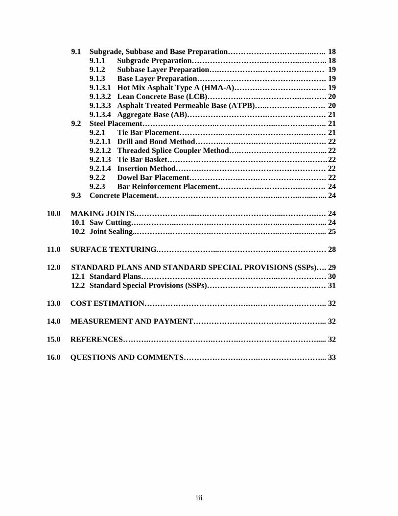
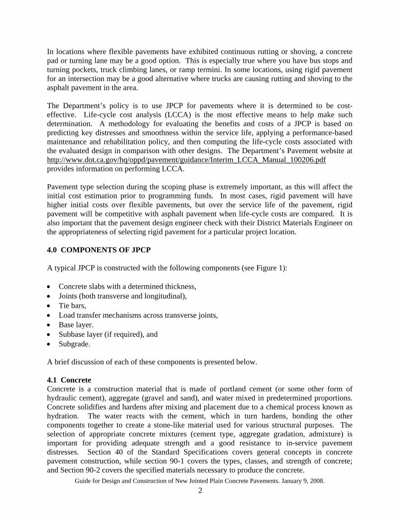
In locations where flexible pavements have exhibited continuous rutting or shoving, a concrete pad or turning lane may be a good option. This is especially true where you have bus stops and turning pockets, truck climbing lanes, or ramp termini. In some locations, using rigid pavement for an intersection may be a good alternative where trucks are causing rutting and shoving to the asphalt pavement in the area. The Department’s policy is to use JPCP for pavements where it is determined to be cost-effective. Life-cycle cost analysis (LCCA) is the most effective means to help make such determination. A methodology for evaluating the benefits and costs of a JPCP is based on predicting key distresses and smoothness within the service life, applying a performance-based maintenance and rehabilitation policy, and then computing the life-cycle costs associated with the evaluated design in comparison with other designs. The Department’s Pavement website at http://www.dot.ca.gov/hq/oppd/pavement/guidance/Interim_LCCA_Manual_100206.pdf provides information on performing LCCA. Pavement type selection during the scoping phase is extremely important, as this will affect the initial cost estimation prior to programming funds. In most cases, rigid pavement will have higher initial costs over flexible pavements, but over the service life of the pavement, rigid pavement will be competitive with asphalt pavement when life-cycle costs are compared. It is also important that the pavement design engineer check with their District Materials Engineer on the appropriateness of selecting rigid pavement for a particular project location. 4.0 COMPONENTS OF JPCP A typical JPCP is constructed with the following components (see Figure 1): • Concrete slabs with a determined thickness, • Joints (both transverse and longitudinal), • Tie bars, • Load transfer mechanisms across transverse joints, • Base layer. • Subbase layer (if required), and • Subgrade. A brief discussion of each of these components is presented below. 4.1 Concrete Concrete is a construction material that is made of portland cement (or some other form of hydraulic cement), aggregate (gravel and sand), and water mixed in predetermined proportions. Concrete solidifies and hardens after mixing and placement due to a chemical process known as hydration. The water reacts with the cement, which in turn hardens, bonding the other components together to create a stone-like material used for various structural purposes. The selection of appropriate concrete mixtures (cement type, aggregate gradation, admixture) is important for providing adequate strength and a good resistance to in-service pavement distresses. Section 40 of the Standard Specifications covers general concepts in concrete pavement construction, while section 90-1 covers the types, classes, and strength of concrete; and Section 90-2 covers the specified materials necessary to produce the concrete.
Guide for Design and Construction of New Jointed Plain Concrete Pavements. January 9, 2008. 3
Figure 1. Components of a Typical JPCP
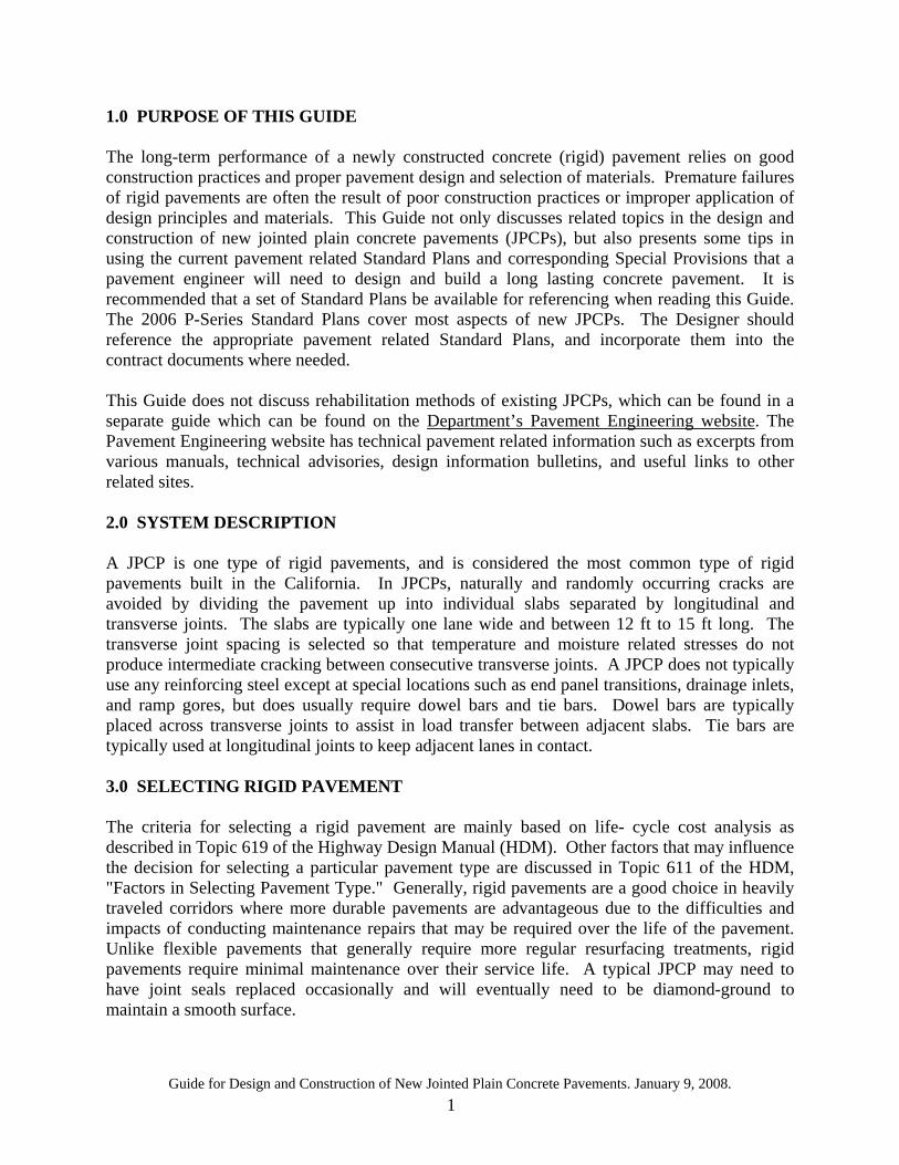
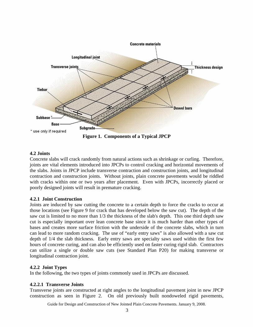
4.2 Joints Concrete slabs will crack randomly from natural actions such as shrinkage or curling. Therefore, joints are vital elements introduced into JPCPs to control cracking and horizontal movements of the slabs. Joints in JPCP include transverse contraction and construction joints, and longitudinal contraction and construction joints. Without joints, plain concrete pavements would be riddled with cracks within one or two years after placement. Even with JPCPs, incorrectly placed or poorly designed joints will result in premature cracking. 4.2.1 Joint Construction Joints are induced by saw cutting the concrete to a certain depth to force the cracks to occur at those locations (see Figure 9 for crack that has developed below the saw cut). The depth of the saw cut is limited to no more than 1/3 the thickness of the slab's depth. This one third depth saw cut is especially important over lean concrete base since it is much harder than other types of bases and creates more surface friction with the underside of the concrete slabs, which in turn can lead to more random cracking. The use of “early entry saws” is also allowed with a saw cut depth of 1/4 the slab thickness. Early entry saws are specialty saws used within the first few hours of concrete curing, and can also be efficiently used on faster curing rigid slab. Contractors can utilize a single or double saw cuts (see Standard Plan P20) for making transverse or longitudinal contraction joint. 4.2.2 Joint Types In the following, the two types of joints commonly used in JPCPs are discussed. 4.2.2.1 Transverse Joints Transverse joints are constructed at right angles to the longitudinal pavement joint in new JPCP construction as seen in Figure 2. On old previously built nondoweled rigid pavements,
Guide for Design and Construction of New Jointed Plain Concrete Pavements. January 9, 2008. 4
transverse joints were skewed. Caltrans has adopted short random patterned transverse joint spacing to reduce thermal movement at each joint and reduce the possibility of mid-panel cracking. The staggered joint spacing of 12, 15, 13 and 14 feet is utilized to reduce harmonic induced ride quality problems. According to the Caltrans HDM Index 622.4, doweled JPCP shall be used for all new state highway construction, lane widening, lane replacement, and reconstruction, especially for truck and HOV lanes. According to HDM Index 622.4, dowel bars are not required when: (1) Rigid shoulders placed or reconstructed next to a non-doweled existing concrete lane (See
Standard Plan P-3) (2) Rigid shoulders placed or reconstructed next to a widened slab (See Standard Plan P-2) (3) Some individual slab replacements (see Standard Plan P-8) Because mechanical load transfer devices (dowel bars) are required in all new JPCPs, skewed transverse joints are not permitted. Dowel bars handle the load transfer and the need for skewing does not provide any significant benefit. Skewing also makes it difficult to place dowels along the transverse joint. Section 4.5 of this Guide provides additional information on load transfer across transverse joints. For lane/shoulder addition or reconstruction, when providing transverse joints, there are cases where the new joints may not line up with the existing transverse joint spacing in the adjacent lane. Standard Plan P18 shows three different cases of existing and new transverse joints alignment that can be encountered when reconstructing or adding concrete lane/shoulder adjacent to existing concrete pavement. To prevent translation of the existing transverse joints over to the new and weaker transverse joints, longitudinal isolation joints (see Section 4.3.1 for this topic) are provided.
Figure 2. Transverse Joints Perpendicular to Lane Lines and Longitudinal Joints
Guide for Design and Construction of New Jointed Plain Concrete Pavements. January 9, 2008. 5
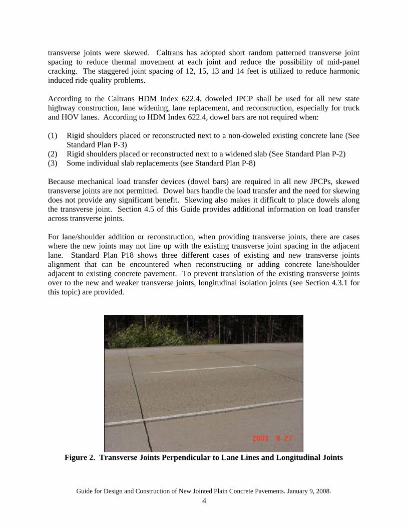
4.2.2.2 Longitudinal Joints Longitudinal joints (see Figure 3) are necessary to control cracking in the longitudinal direction where two or more lane widths are placed at one time. They are constructed at lane lines, typically in multiples of 12 feet. Tie bars (see Section 4.4) are placed at these joints to hold two abutting rigid pavement faces in contact.
Figure 3. Longitudinal Joint at Lane Line
4.3 Other Joints 4.3.1 Isolation Joint An isolation joint is a special longitudinal joint that is placed to prevent existing transverse joints or transverse working joints (joints that accommodate movements) from extending into the weaker newly placed rigid pavement. Isolation joints should be used when matching the existing transverse joints is not practical. They are placed to separate dissimilar rigid pavements/structures in order to reduce compressive stresses that could cause uncontrolled cracking. An isolation joint is required in (1) lane/shoulder addition or reconstruction where transverse joints do not align between new and existing, for which tie bars are required at the isolation joint, (2) interior lane replacement where joints do not align between new and existing, and (3) lane/shoulder addition or reconstruction where transverse joints align between new and existing, where tie bars are not required for the isolation joint. When adding the new lane, in many instances, an asphalt shoulder is removed. This may leave the abutting edge of concrete slab surface rough that will require saw cutting to remove any protruding pockets of concrete. This sawing requirement is covered in SSP 40-010. The isolation joint prevents the joints and cracks in the adjacent lane from propagating to the new added lane. A joint filler material is used to fill the isolation joint to prevent infiltration of
Guide for Design and Construction of New Jointed Plain Concrete Pavements. January 9, 2008. 6
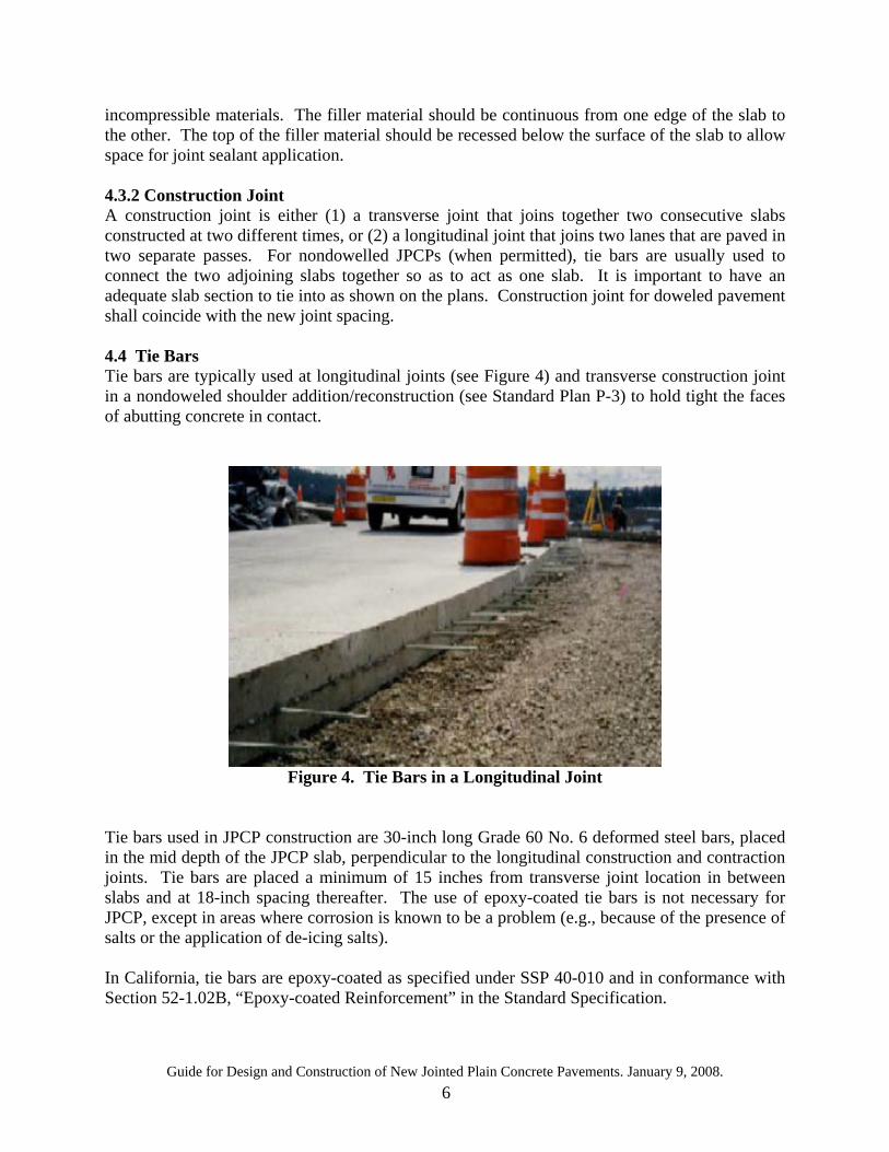
incompressible materials. The filler material should be continuous from one edge of the slab to the other. The top of the filler material should be recessed below the surface of the slab to allow space for joint sealant application. 4.3.2 Construction Joint A construction joint is either (1) a transverse joint that joins together two consecutive slabs constructed at two different times, or (2) a longitudinal joint that joins two lanes that are paved in two separate passes. For nondowelled JPCPs (when permitted), tie bars are usually used to connect the two adjoining slabs together so as to act as one slab. It is important to have an adequate slab section to tie into as shown on the plans. Construction joint for doweled pavement shall coincide with the new joint spacing. 4.4 Tie Bars Tie bars are typically used at longitudinal joints (see Figure 4) and transverse construction joint in a nondoweled shoulder addition/reconstruction (see Standard Plan P-3) to hold tight the faces of abutting concrete in contact.
Figure 4. Tie Bars in a Longitudinal Joint
Tie bars used in JPCP construction are 30-inch long Grade 60 No. 6 deformed steel bars, placed in the mid depth of the JPCP slab, perpendicular to the longitudinal construction and contraction joints. Tie bars are placed a minimum of 15 inches from transverse joint location in between slabs and at 18-inch spacing thereafter. The use of epoxy-coated tie bars is not necessary for JPCP, except in areas where corrosion is known to be a problem (e.g., because of the presence of salts or the application of de-icing salts). In California, tie bars are epoxy-coated as specified under SSP 40-010 and in conformance with Section 52-1.02B, “Epoxy-coated Reinforcement” in the Standard Specification.

Guide for Design and Construction of New Jointed Plain Concrete Pavements. January 9, 2008. 7
There is a limit of 50 ft wide tied JPCP lanes, based on national experience. When more lanes are tied together, there seems to be a tendency for the concrete slab to crack longitudinally. When the slabs are tied together they act as one slab and the friction between the base and the slabs is high enough to restrain movement, thus causing cracking in some cases. Therefore, tie bars should be omitted at one of the longitudinal joints when more than 4 lanes (or 3 lanes and a shoulder) are being tied together. The preferred longitudinal joint to omit tie bars would be an inside lane where truck or bus traffic will not occur. Standard Plan P18 includes lane schematics that cover most cases for isolation joint placement. Tie bars are recommended at longitudinal construction joints for lane/shoulder addition or reconstruction, but not recommended where isolation joints are required. Dowel bars (see below) at longitudinal joints without tie bars may be useful when there is a need to obtain some limited load transfer across the longitudinal joint. Standard Plan P-18 provides schematics on when and how to apply contact joints, isolation joints, and when to use dowel bars in lieu of tie bars. 4.5 Load Transfer Load transfer is the ability of a joint to transfer a portion of an applied load (the truck wheel) from one side of the joint to the other. Joint transfer is achieved by (1) mechanical load transfer devices such as dowel bars, (2) aggregate interlock across abutting edges of concrete, and (3) friction between concrete and stabilized base [lean concrete base, hot mixed asphalt, asphalt treated base, cement treated base, etc.]. The ideal transverse joint is one that has all three mechanisms available. The current Caltrans standard practice utilizes lean concrete or hot mixed asphalt as the base, dowel bars, and aggregate interlock. In the following a brief discussion of each mechanism is provided. 4.5.1 Dowel Bars Dowel bars are made of smooth, round, epoxy-coated Grade 60 steel bars that allow load transfer across the joint without restricting horizontal movement (see Figure 5). Dowel bars provide lower deflection, prevent pumping, corner breaks, and excessive slab curling and reduce the potential for faulting; thus keeping a smooth-riding pavement. Slab movements (rocking) are significantly reduced with the use of dowel bars as schematically seen in Figures 6 and 7 for dowelled and non-dowelled transverse joints. Generally, the number of dowel bars required along the transverse joint is dictated by the width of the slab.
Guide for Design and Construction of New Jointed Plain Concrete Pavements. January 9, 2008. 8
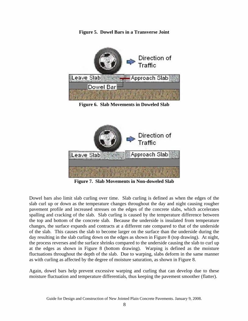
Figure 5. Dowel Bars in a Transverse Joint
Figure 6. Slab Movements in Doweled Slab
Figure 7. Slab Movements in Non-doweled Slab
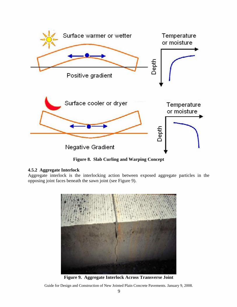
Dowel bars also limit slab curling over time. Slab curling is defined as when the edges of the slab curl up or down as the temperature changes throughout the day and night causing rougher pavement profile and increased stresses on the edges of the concrete slabs, which accelerates spalling and cracking of the slab. Slab curling is caused by the temperature difference between the top and bottom of the concrete slab. Because the underside is insulated from temperature changes, the surface expands and contracts at a different rate compared to that of the underside of the slab. This causes the slab to become larger on the surface than the underside during the day resulting in the slab curling down on the edges as shown in Figure 8 (top drawing). At night, the process reverses and the surface shrinks compared to the underside causing the slab to curl up at the edges as shown in Figure 8 (bottom drawing). Warping is defined as the moisture fluctuations throughout the depth of the slab. Due to warping, slabs deform in the same manner as with curling as affected by the degree of moisture saturation, as shown in Figure 8. Again, dowel bars help prevent excessive warping and curling that can develop due to these moisture fluctuation and temperature differentials, thus keeping the pavement smoother (flatter).
Guide for Design and Construction of New Jointed Plain Concrete Pavements. January 9, 2008. 9
Figure 8. Slab Curling and Warping Concept
4.5.2 Aggregate Interlock Aggregate interlock is the interlocking action between exposed aggregate particles in the opposing joint faces beneath the sawn joint (see Figure 9).
Figure 9. Aggregate Interlock Across Transverse Joint
Guide for Design and Construction of New Jointed Plain Concrete Pavements. January 9, 2008. 10
For non-doweled JPCP, aggregate interlock (jagged crack area) beneath the saw cut portion of the joint provides most of the load transfer. Over time these aggregate interlock faces can wear and load transfer can drop. Because aggregate interlock deteriorates over time, especially when there are no dowel bars and/or stabilized base, Caltrans current practice requires dowel bars in all but a limited number of cases. Where truck volumes are low, there are standard designs available that do not require the stabilized base. 4.5.3 Stabilized Base Stabilized bases utilize a small percentage of cement or asphalt binder to stiffen the base, and can provide friction with the concrete slabs resting on them; thus helping in transferring the load from one side of the joint to the other. Historically, Caltrans used stabilized base (primarily cement treated base) with its pavements, which were non-doweled. Experience, however, has shown that these pavements fault prematurely requiring increased maintenance and earlier rehabilitation. Current design practice requires both dowel bars and stabilized base for pavements subject to high truck volumes. Because pavements with dowel bars have shown to be more cost effective and provide better performance than no-doweled pavements, current design practice for low volume routes still requires dowel bars but does provide designs that do not require a stabilized base. 4.6 Subgrade, Subbase and Base Rigid pavements require base and, in some cases, subbase layer for structural support since the applied traffic loads is transferred across the rigid structure by providing only bearing stress applied to the underlying foundation. Base and subbase provide a working platform during construction. The majority of rigid pavements fail not because of concrete slab failure but by failure of materials below the concrete slab due to unstable or non-uniform materials, poor compaction, or poor drainage (e.g., either underground water percolating into the base or surface water leaching through the concrete and becoming trapped in the base). 4.6.1 Subgrade The load-bearing capacity of the subgrade soil has a significant impact on the performance of a JPCP. Anything that can be done to increase the load-bearing capacity or structural support of the subgrade will likely improve the overall strength and performance of the pavement. Generally, greater subgrade structural capacity can result in more economical pavement structures. Subgrade soil can vary widely over a short distance. Poor subgrade can be described as expansive (plasticity index greater than 12 and/or R-value of less than 10). Index 614.2 in the HDM states that organic and peat soils are compressible and not recommended for roadway construction. They should be removed, wherever possible, prior to placing the pavement structure. Subgrade stabilization is desirable for poor subgrade material under a rigid pavement. For example, lime may be used with expansive soils, cement with less plastic soils (plasticity index less than 10), and emulsified asphalt can be used with sandy soils2. The binding characteristics of these materials generally increase the subgrade load bearing capacity. To
Guide for Design and Construction of New Jointed Plain Concrete Pavements. January 9, 2008. 11
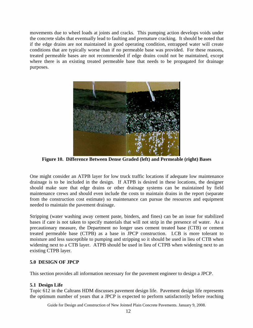
eliminate or reduce subgrade moisture, installation of subdrains is necessary. Topic 614 in the HDM explains soil characteristics, testing, and available treatment options. 4.6.2 Subbase Layer The subbase layer is a planned thickness of specified material that is placed on the subgrade or under the basement material. This layer is not always used, but when it is needed it can provide for structural strength and/or a working platform. 4.6.3 Base Layer The base layer is immediately placed beneath the surface course. It can be treated (stabilized, bound) or untreated (unbound, unstabilized). It can provide a stable platform for the concrete paving, provides for additional load distribution, and contributes to drainage (if permeable base is used) and frost resistance. The primary purpose of the unbound aggregate or granular material is for structural support, but other uses include (1) improve drainage, (2) minimize frost action damage and (3) minimize intrusion of fines from the subgrade into the pavement structure. Stabilized bases are the standard for all JPCPs with a Traffic Index (TI) greater than 11. For lower TI values, unstabilized aggregate base maybe used. The Department uses stabilized bases to provide a construction platform for the concrete paving machine and to minimize base erosion and the development of voids underneath the concrete slabs. Current standard designs use either lean concrete base or Hot Mix Asphalt–Type A (HMA-A). Lean concrete base (LCB) is the typical type of base for JPCP primarily because it not only provides a stable platform for the rigid slab but is also constructed using the same plants and equipment as concrete. Lean concrete base is more rigid and less erodible than cement treated base (CTB). The September 1, 2006 Caltrans HDM edition (June 26, 2006 Metric edition) states that concrete can be substituted for LCB when justified for constructability or traffic handling. JPCP should not be bonded with LCB. A 1-inch thick interlayer of HMA-A should be placed between the JPCP and LCB. Hot Mix Asphalt–A (HMA-A) is another alternative to lean concrete base. It provides a smooth base layer, reduces friction, and provides a good bond breaker layer. HMA-A base layer consists of a combination of mineral aggregates and asphalt materials mixed mechanically in a plant. HMA-A provides flexibility to expand and contract with temperature fluctuations. HMA-A typically performs better than LCB in hotter climate regions like the desert environments and southern central valley because it provides more flexibility for concrete to expand and contract with temperature fluctuation. Asphalt Treated Permeable Bases (ATPB) has been used in the past to address water infiltration. This type of permeable base is useful where it is necessary to drain water beneath the pavement (see Figure 10). Water can enter the pavement as surface water through cracks, joints, and pavement infiltration. Saturation of the pavement or underlying subgrade, or both, generally results in a decrease in strength or ability to support heavy axle loads. Treated permeable base requires the use of edge drains or some other method of draining water out and away from the pavement. Otherwise, the collected water will become trapped. Trapping water beneath the concrete could create an undesirable condition known as pumping. Pumping removes fines from the saturated base layer (especially untreated ones) by creating dynamic upward and downward
Guide for Design and Construction of New Jointed Plain Concrete Pavements. January 9, 2008. 12
movements due to wheel loads at joints and cracks. This pumping action develops voids under the concrete slabs that eventually lead to faulting and premature cracking. It should be noted that if the edge drains are not maintained in good operating condition, entrapped water will create conditions that are typically worse than if no permeable base was provided. For these reasons, treated permeable bases are not recommended if edge drains could not be maintained, except where there is an existing treated permeable base that needs to be propagated for drainage purposes.
Figure 10. Difference Between Dense Graded (left) and Permeable (right) Bases
One might consider an ATPB layer for low truck traffic locations if adequate low maintenance drainage is to be included in the design. If ATPB is desired in these locations, the designer should make sure that edge drains or other drainage systems can be maintained by field maintenance crews and should even include the costs to maintain drains in the report (separate from the construction cost estimate) so maintenance can pursue the resources and equipment needed to maintain the pavement drainage. Stripping (water washing away cement paste, binders, and fines) can be an issue for stabilized bases if care is not taken to specify materials that will not strip in the presence of water. As a precautionary measure, the Department no longer uses cement treated base (CTB) or cement treated permeable base (CTPB) as a base in JPCP construction. LCB is more tolerant to moisture and less susceptible to pumping and stripping so it should be used in lieu of CTB when widening next to a CTB layer. ATPB should be used in lieu of CTPB when widening next to an existing CTPB layer. 5.0 DESIGN OF JPCP This section provides all information necessary for the pavement engineer to design a JPCP. 5.1 Design Life Topic 612 in the Caltrans HDM discusses pavement design life. Pavement design life represents the optimum number of years that a JPCP is expected to perform satisfactorily before reaching
Guide for Design and Construction of New Jointed Plain Concrete Pavements. January 9, 2008. 13
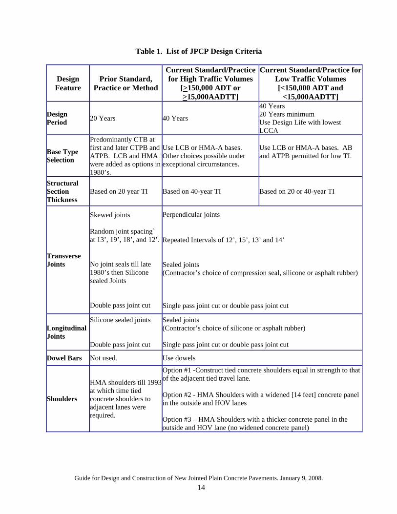
its terminal serviceability or reaching a condition that requires Capital Preventive Maintenance (CAPM). Generally, the HDM and this Guide recommend that JPCP be designed for a service life of 20 or 40 years depending on traffic volume and type of facility. See Table 612.2 in the HDM for determining the required design life. 5.2 Pavement Performance Factors Pavement performance factors for JPCP can be found in Table 622.2 in the HDM. JPCP performance is primarily based on transverse, longitudinal, and corner cracking at end of design life and joint faulting. 5.3 Design Thicknesses Topic 623 in the HDM should be used to determine the required thickness of concrete slabs , and the thickness and type of the base and subbase layers. The thicknesses of the various layers are affected by the traffic index (TI), subgrade type (R-value), climatic conditions, and whether the concrete lane has lateral support along the longitudinal joints, as all explained in Topic 623 in the HDM. These thicknesses can be used for new construction, reconstruction, widening, and lane replacement. Designs with thicknesses and/or materials that are different from those given in the tables and the instructions given in Topic 623 are considered to be special designs requiring review and concurrence from the Headquarters Office of Pavement Design (HDM 606.2). As an example on the design of a new JPCP, consider the following information. A two-mile section of I-5 near Sacramento is planned for reconstruction. The traffic index, TI, is 13.0. Shoulders will be made of concrete and tied to the mainline. The adjacent lane has an existing LCB layer. The subgrade at that location has an R-value of 30 and is classified as CH using the Unified Soil Classification System. Design a JPCP section that can provide adequate pavement structure for a given traffic. For this example, Sacramento is located in the Inland Valley climate region as shown on the climate map given in the pavement website at http://www.dot.ca.gov/hq/oppd/pavement/Pavement_Climateregions_100505.pdf. Using Table 623.1A, with R-value of 30 and a CH soil type, the subgrade type is determined as Type II. From Figure 623.1, it is determined that Table 623.1G should be used. With TI=13, and with lateral support, Table 623.1G shows that the structural section that should be used is either 225 mm JPCP/150 mm LCB/210 mm AS or 270 mm JPCP/150 mm HMA/210 mm AS. The design engineer should evaluate the condition of the adjacent lanes to determine which section to select for this reconstruction project. To ensure consistency with the existing pavement layers, and because LCB can be obtained from the same plant and placed using the same equipment used for placing concrete, the use of 225 mm JPCP/150 mm LCB/210 mm AS seems to be a more desirable design. 6.0 JPCP DESIGN - THEN AND NOW Table 1 below provides a comparison summary between current and previous JPCP design criteria. Note that high traffic corridors do require more initial capital cost but provide for much more durable pavement.
Guide for Design and Construction of New Jointed Plain Concrete Pavements. January 9, 2008. 14
Table 1. List of JPCP Design Criteria
Design Feature
Prior Standard, Practice or Method
Current Standard/Practice for High Traffic Volumes
[>150,000 ADT or >15,000AADTT]
Current Standard/Practice for Low Traffic Volumes [<150,000 ADT and
<15,000AADTT]
Design Period 20 Years 40 Years
40 Years 20 Years minimum Use Design Life with lowest LCCA
Base Type Selection
Predominantly CTB at first and later CTPB and ATPB. LCB and HMA were added as options in 1980’s.
Use LCB or HMA-A bases. Other choices possible under exceptional circumstances.
Use LCB or HMA-A bases. AB and ATPB permitted for low TI.
Structural Section Thickness
Based on 20 year TI Based on 40-year TI Based on 20 or 40-year TI
Transverse Joints
Skewed joints Random joint spacing` at 13’, 19’, 18’, and 12’. No joint seals till late 1980’s then Silicone sealed Joints Double pass joint cut
Perpendicular joints Repeated Intervals of 12’, 15’, 13’ and 14’ Sealed joints (Contractor’s choice of compression seal, silicone or asphalt rubber) Single pass joint cut or double pass joint cut
Longitudinal Joints
Silicone sealed joints Double pass joint cut
Sealed joints (Contractor’s choice of silicone or asphalt rubber) Single pass joint cut or double pass joint cut
Dowel Bars Not used. Use dowels
Shoulders
HMA shoulders till 1993 at which time tied concrete shoulders to adjacent lanes were required.
Option #1 -Construct tied concrete shoulders equal in strength to that of the adjacent tied travel lane. Option #2 - HMA Shoulders with a widened [14 feet] concrete panel in the outside and HOV lanes Option #3 – HMA Shoulders with a thicker concrete panel in the outside and HOV lane (no widened concrete panel)
Guide for Design and Construction of New Jointed Plain Concrete Pavements. January 9, 2008. 15
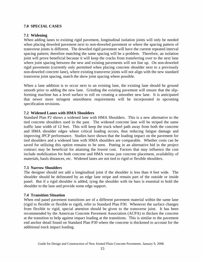
7.0 SPECIAL CASES 7.1 Widening When adding lanes to existing rigid pavement, longitudinal isolation joints will only be needed when placing doweled pavement next to non-doweled pavement or where the spacing pattern of transverse joints is different. The doweled rigid pavement will have the current repeated interval spacing pattern; therefore matching the same spacing will be a problem. Therefore, an isolation joint will prove beneficial because it will keep the cracks from transferring over to the next lane where joint spacing between the new and existing pavements will not line up. On non-doweled rigid pavements (currently only permitted when placing concrete shoulder next to a previously non-doweled concrete lane), where existing transverse joints will not align with the new standard transverse joint spacing, match the skew joint spacing where possible. When a lane addition is to occur next to an existing lane, the existing lane should be ground smooth prior to adding the new lane. Grinding the existing pavement will ensure that the slip-forming machine has a level surface to roll on creating a smoother new lane. It is anticipated that newer more stringent smoothness requirements will be incorporated in upcoming specification revisions. 7.2 Widened Lanes with HMA Shoulders Standard Plan P2 shows a widened lane with HMA Shoulders. This is a new alternative to the tied concrete shoulders used in the past. The widened concrete lane will be striped the same traffic lane width of 12 feet. This will keep the truck wheel path away from both the concrete and HMA shoulder edges where critical loading occurs, thus reducing fatigue damage and improving JPCP performance. Studies have shown that the loading impact on the pavement for tied shoulders and a widened lane with HMA shoulders are comparable. Whether costs can be saved for utilizing this option remains to be seen. Putting in an alternative bid in the project contract may be beneficial for attaining the lowest cost. Factors that may influence the cost include mobilization for both concrete and HMA versus just concrete placement, availability of materials, hauls distances, etc. Widened lanes are not tied to rigid or flexible shoulders. 7.3 Narrow Shoulders The designer should not add a longitudinal joint if the shoulder is less than 4 feet wide. The shoulder should be delineated by an edge lane stripe and remain part of the outside or inside panel. But if a rigid shoulder is added, tying the shoulder with tie bars is essential to hold the shoulder to the lane and provide some edge support. 7.4 Transition Situation When end panel pavement transitions are of a different pavement material within the same lane (rigid to flexible or flexible to rigid), refer to Standard Plan P30. Whenever the surface changes from flexible to rigid, special attention should be given to the transverse joint. It has been recommended by the American Concrete Pavement Association (ACPA) to thicken the concrete at the transition to help against impact loading at the transitions. This is similar to the pavement end anchor detail found on Standard Plan P30 where the concrete is thickened to account for the additional truck impact loading.
Guide for Design and Construction of New Jointed Plain Concrete Pavements. January 9, 2008. 16
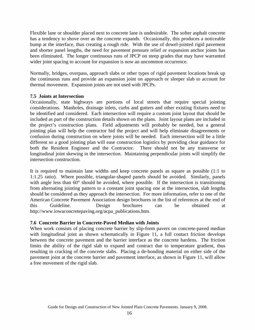
Flexible lane or shoulder placed next to concrete lane is undesirable. The softer asphalt concrete has a tendency to shove over as the concrete expands. Occasionally, this produces a noticeable bump at the interface, thus creating a rough ride. With the use of dowel-jointed rigid pavement and shorter panel lengths, the need for pavement pressure relief or expansion anchor joints has been eliminated. The longer continuous runs of JPCP on steep grades that may have warranted wider joint spacing to account for expansion is now an uncommon occurrence. Normally, bridges, overpass, approach slabs or other types of rigid pavement locations break up the continuous runs and provide an expansion joint on approach or sleeper slab to account for thermal movement. Expansion joints are not used with JPCPs. 7.5 Joints at Intersection Occasionally, state highways are portions of local streets that require special jointing considerations. Manholes, drainage inlets, curbs and gutters and other existing fixtures need to be identified and considered. Each intersection will require a custom joint layout that should be included as part of the construction details shown on the plans. Joint layout plans are included in the project’s construction plans. Field adjustments will probably be needed, but a general jointing plan will help the contractor bid the project and will help eliminate disagreements or confusion during construction on where joints will be needed. Each intersection will be a little different so a good jointing plan will ease construction logistics by providing clear guidance for both the Resident Engineer and the Contractor. There should not be any transverse or longitudinal joint skewing in the intersection. Maintaining perpendicular joints will simplify the intersection construction. It is required to maintain lane widths and keep concrete panels as square as possible (1:1 to 1:1.25 ratio). Where possible, triangular-shaped panels should be avoided. Similarly, panels with angle less than 60° should be avoided, where possible. If the intersection is transitioning from alternating jointing pattern to a constant joint spacing one at the intersection, slab lengths should be considered as they approach the intersection. For more information, refer to one of the American Concrete Pavement Association design brochures in the list of references at the end of this Guideline. Design brochures can be obtained at http://www.iowaconcretepaving.org/acpa_publications.htm. 7.6 Concrete Barrier in Concrete-Paved Median with Joints When work consists of placing concrete barrier by slip-form pavers on concrete-paved median with longitudinal joint as shown schematically in Figure 11, a full contact friction develops between the concrete pavement and the barrier interface as the concrete hardens. The friction limits the ability of the rigid slab to expand and contract due to temperature gradient, thus resulting in cracking of the concrete slabs. Placing a de-bonding material on either side of the pavement joint at the concrete barrier and pavement interface, as shown in Figure 11, will allow a free movement of the rigid slab.
Guide for Design and Construction of New Jointed Plain Concrete Pavements. January 9, 2008. 17
Figure 11 Concrete Barrier on Longitudinal Joint without Tie Bar
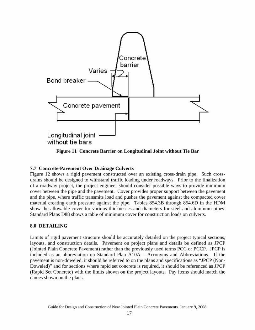
7.7 Concrete-Pavement Over Drainage Culverts Figure 12 shows a rigid pavement constructed over an existing cross-drain pipe. Such cross-drains should be designed to withstand traffic loading under roadways. Prior to the finalization of a roadway project, the project engineer should consider possible ways to provide minimum cover between the pipe and the pavement. Cover provides proper support between the pavement and the pipe, where traffic transmits load and pushes the pavement against the compacted cover material creating earth pressure against the pipe. Tables 854.3B through 854.6D in the HDM show the allowable cover for various thicknesses and diameters for steel and aluminum pipes. Standard Plans D88 shows a table of minimum cover for construction loads on culverts. 8.0 DETAILING Limits of rigid pavement structure should be accurately detailed on the project typical sections, layouts, and construction details. Pavement on project plans and details be defined as JPCP (Jointed Plain Concrete Pavement) rather than the previously used terms PCC or PCCP. JPCP is included as an abbreviation on Standard Plan A10A – Acronyms and Abbreviations. If the pavement is non-doweled, it should be referred to on the plans and specifications as “JPCP (Non-Doweled)” and for sections where rapid set concrete is required, it should be referenced as JPCP (Rapid Set Concrete) with the limits shown on the project layouts. Pay items should match the names shown on the plans.
Guide for Design and Construction of New Jointed Plain Concrete Pavements. January 9, 2008. 18
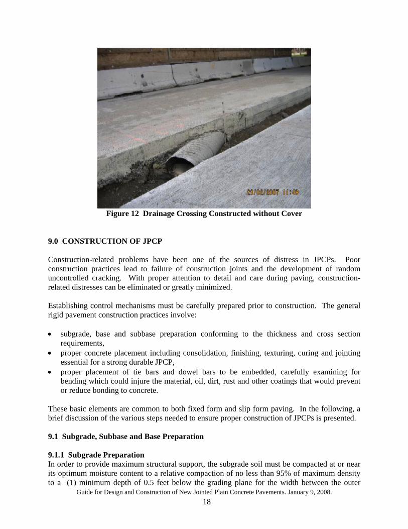
Figure 12 Drainage Crossing Constructed without Cover
9.0 CONSTRUCTION OF JPCP Construction-related problems have been one of the sources of distress in JPCPs. Poor construction practices lead to failure of construction joints and the development of random uncontrolled cracking. With proper attention to detail and care during paving, construction-related distresses can be eliminated or greatly minimized. Establishing control mechanisms must be carefully prepared prior to construction. The general rigid pavement construction practices involve: • subgrade, base and subbase preparation conforming to the thickness and cross section
requirements, • proper concrete placement including consolidation, finishing, texturing, curing and jointing
essential for a strong durable JPCP, • proper placement of tie bars and dowel bars to be embedded, carefully examining for
bending which could injure the material, oil, dirt, rust and other coatings that would prevent or reduce bonding to concrete.
These basic elements are common to both fixed form and slip form paving. In the following, a brief discussion of the various steps needed to ensure proper construction of JPCPs is presented. 9.1 Subgrade, Subbase and Base Preparation 9.1.1 Subgrade Preparation In order to provide maximum structural support, the subgrade soil must be compacted at or near its optimum moisture content to a relative compaction of no less than 95% of maximum density to a (1) minimum depth of 0.5 feet below the grading plane for the width between the outer
Guide for Design and Construction of New Jointed Plain Concrete Pavements. January 9, 2008. 19
edges of shoulders, or (2) minimum depth of 2.5 feet below the finished grade for the width of the traveled way and auxiliary lanes including 3 feet on both sides as specified in Section 19-5.03 of the Standard Specifications when tested in accordance with Test Methods 216 and 231. Compression, deformation or erosion of the subgrade after construction may occur if minimum compaction requirement was not achieved, causing premature pavement cracking. The minimum depth of 2.5 feet can be waived in the following situations: • a portion of a local road is being replaced with stronger pavement structure, • partial depth reconstruction, • presence of existing utilities are to be moved, and • interim widening project is required on low volume roads, intersections, or frontage roads. Location where the 2.50 feet compaction depth is waived must be shown on the typical cross sections of the project plans. Any imported borrow to replace soft or unsuitable material or use of subgrade enhancement geotextile in construction should be identified and shown. There is no minimum California R-value required by the Standard Specification for imported borrows used in the construction of embankments; therefore a minimum must be specified by Special Provision to cover the material placed within 4 feet of the finished grade (see Index 614.6 (2) – Imported Borrow in the HDM). 9.1.2 Subbase Layer Preparation The Department uses Aggregate Subbase (AS) for use in JPCP construction to provide a foundation or working platform for the base when the subgrade R-value is less than 40. Aggregates may include any of the processed materials from reclaimed asphalt concrete, reclaimed lean concrete base, reclaimed cement treated base, reclaimed portland cement concrete, provided that the mixture meets the requirements in the specifications. Aggregate base (AB) may be substituted for aggregate subbase (AS) but the thickness shall not be reduced. Aggregate subbases are delivered as uniform mixes, clean and free from organic matter, deposited to the roadbed in layers or windrows, spread without segregation, free from pockets of fine and coarse materials, and shaped to a thickness such that the completed subbase conforms to the required grade and cross section. The maximum thickness of any one layer should not exceed 0.50 foot after watering and compaction. Where the required thickness is more than 0.50 foot, spreading, watering and compaction should be conducted in 2 or more lifts of approximately equal thickness. Upon completion of compaction, no construction traffic should be allowed on the subbase layer. Compaction of aggregate subbase is specified in Section 25-1.05, “Compaction” of the Standard Specification”. 9.1.3 Base Layer Preparation The Department uses Hot Mix Asphalt (HMA) Type A, Lean Concrete Base (LCB), Asphalt Treated Permeable Base (ATPB), and Aggregate Base (AB) to provide a construction platform underneath the JPCP. See Table 623.1 in the HDM for the various types of bases and where they should be used. In the following the preparation of each type of these base materials is discussed. 9.1.3.1 Hot Mix Asphalt Type A (HMA-A) HMA-Type A consists of one or more layers placed on a prepared subbase or subgrade in conformity with the alignment and grades shown on the project plans. HMA-A is placed at a
Guide for Design and Construction of New Jointed Plain Concrete Pavements. January 9, 2008. 20
temperature of no less than 310 °F and only when the subbase or subgrade surface is dry and in satisfactory condition. Note that in the majority of cases (see Table 623.1 of the HDM) the base layer is placed directly on finished subgrade. When required, prime coat of liquid asphalt can be applied to the area of the subbase or subgrade to receive the HMA. Tack coat (paint binder) shall also be applied between lifts of HMA. All loose material must be completely removed from the primed subgrade before placing HMA as a base. All breakdown compaction must be completed before the temperature of the HMA mixture falls below 200 °F. HMA is spread and compacted in a number of lifts. Each layer of compacted HMA base thicknesses is 0.20-foot minimum and 0.40-foot maximum. In order to provide maximum structural support, the completed deep lift of the HMA-A base course shall have a minimum density of 92 percent and a maximum density of 96 percent of the laboratory density, based on the Job-Mix Formula for the asphalt mixture when tested in accordance with California Test 304 and ASTM D 1188, California Test Method 308, or California Test Method 375. 9.1.3.2 Lean Concrete Base (LCB) LCB is placed, constructed and finished in no less than 12-foot widths separated by contact joints. Widths that are greater than 26 feet are constructed with longitudinal weakened plane joints at no more than 3 feet from the centerline of the width being constructed. The following steps are undertaken during the course of work in placing LCB: • for placing and applying curing compound, ensure the subgrade is not frozen and the ambient
temperature is at or above 35 °F. • as it is placed, observe for any improper proportions or inadequate mixing. A liberal amount of curing compound is applied as outlined in the specifications. In addition to protecting the LCB while it cures, the curing compound helps serve as a bond breaker between the LCB and JPCP. Because of this, if the curing compound is worn off by construction traffic or other activities, it should be reapplied prior to placing concrete on the LCB. In several projects built in the past, JPCP has bonded to the LCB while it cures causing cracks in the LCB to propagate through the JPCP layer. The finished surface area of the LCB is measured and recorded. Areas that do not meet the elevation requirements require specified corrections, and curing compound is reapplied to those high areas that have been ground. Traffic or contractors’ equipment could be allowed on the finished LCB layer; however, load limitations specified in the Standard Specifications should be enforced. 9.1.3.3 Asphalt Treated Permeable Base (ATPB) Many of the requirements for producing and the manner of placing and compacting ATPB are also those specified for asphalt concrete. As can be seen in Table 623.1 in the HDM, ATPB cannot be placed directly on subgrade, but requires an AS layer beneath it. Placement of ATPB on finished AS layer shall proceed in the same way HMA-A base layer is placed on finished base or subgrade. The finished surface of ATPB, at any point, shall not vary by more than 0.05 foot above or below the established grade determined by the Engineer, and damage to the base should be repaired promptly.
Guide for Design and Construction of New Jointed Plain Concrete Pavements. January 9, 2008. 21
9.1.3.4 Aggregate Base (AB) Aggregate base Class 2 used in JPCP construction can include material processed from reclaimed HMA, PCC, LCB, CTB or combination of any of these materials provided that the mixture meets the requirements in the specifications. The aggregate base can be placed directly on original ground whenever it is allowed (see Table 623.1 in the HDM). For those cases, test and verify the design R-value of the basement material (subgrade) at the grading plane. This is to ensure adequate thickness of the base layer. To allow time for redesign if necessary, completion of testing early enough is necessary before the placement of the aggregate base. Any necessary adjustments in thickness are usually made in the aggregate base. The contractor is not allowed to process material on the roadbed to make it comply with grading specifications. Therefore, before the AB material is placed on the roadbed, the contractor must remove any oversized material and do any necessary blending. At locations that are inaccessible to the spreading equipment, AB may be spread in one or more layers to get to the required results. Aggregate base, where the required thickness is 0.50-foot or less, is spread and compacted in one layer. If the required thickness is more than 0.50-foot, spread and compact AB in two or more lifts in approximately equal thickness, and each lift shall not exceed 0.50-foot. Ensure all base layers mentioned are being placed without significant segregation. The relative compaction of base layers shall not be allowed to go below 95%. The amount of testing necessary is based on the material’s uniformity and the particular operation. Generally, if the operation is uniform and well within specifications, testing frequency may decrease. For non-uniform operations with borderline results, increase testing frequency. 9.2 Steel Placement Ensuring that proper placement of steel (used for tie bars and dowel bars) is one concern in the construction of JPCP. Improper placement or alignment has been the cause of much JPCP distress. A frequent check of steel placement during construction is necessary. The general cleanliness of steel must also be checked for ensuring it does not have loose mill scale, excessive rust, or other deleterious coatings. Advise the contractor if cleaning is necessary. Epoxy coatings should also be checked for chips and scratches that can allow water to penetrate the coating and cause the steel to rust. Refer to Section 4.4-Tie Bar, and Section 4.5.1-Dowel Bars of this Guide for the type and grade of steel used. 9.2.1 Tie Bar Placement Tie bars are not to be used at a joint where concrete and asphalt concrete pavements abut. Tie bars are placed (a) along longitudinal weakened plane in multilane paving, and (b) at longitudinal and transverse contact joint in a nondoweled lane/shoulder addition or reconstruction. These tie bars are placed at mid depth of the concrete slab. In the past, tie bar placement along the longitudinal contact joint was done using 90° bent bars when there was a traffic staging or constructability reason. These bent tie bars are inserted into the side of the slab while paving and then straightened before placing the adjacent lane. Even if the tie bars are epoxy coated with the more flexible green coating, there was a tendency for the tie bar coating to break when bent. Also, frequently the stronger the yield strength of steel rebar, the more brittle it will be when bent at 90º. For these reasons, bending of tie bars is no longer allowed. Instead, if
Guide for Design and Construction of New Jointed Plain Concrete Pavements. January 9, 2008. 22
it is not possible to place tie bars in a cold joint unbent, the tie bars should be omitted from the initial concrete placement and then drilled and grouted into the hardened concrete before placing the adjacent concrete. The following methods are the proper way recommended for installing tie bars at the longitudinal joints of JPCPs: 9.2.1.1 Drill and Bond Method Holes are drilled into the exposed longitudinal contact or transverse construction joint of the hardened concrete and cleaned before fresh concrete is poured. At the time of filling the holes with epoxy, the drilled holes should be dried followed by inserting the tie bars. Tie bars are rotated 180º while being inserted into the epoxy filled holes. Immediately after insertion, use supports to prevent movement until the epoxy has cured. Improperly placed or bonded tie bars are rejected and new holes are drilled and new tie bars are placed and securely bonded to the concrete. Tie bars that are rejected are cut flush with the joint face. 9.2.1.2 Threaded Splice Coupler Method This is an alternate method of tie bar placement. As shown in Standard Plan P1 – Alternative Tie Bar Detail (Splice Coupler), tie bar is fabricated from deformed bar reinforcement material, free of external welding. 9.2.1.3 Tie Bar Basket This method is applicable in multilane paving operation where more than one lane or shoulder width is placed at one time. Tie bar baskets are placed along planned longitudinal weakened plane joints, assembled in a tie bar basket in A or U shape assembly frames, placed on properly inspected base or subbase perpendicular to the pavement longitudinal edges. Tie bars are located at the mid-depth of the slab, carefully aligned horizontally and vertically. When the bars are correctly aligned, the tie bar baskets must be secured with concrete nails used specifically for fastening to harden concrete or asphalt concrete. A minimum of 8 alternating equally spaced fasteners, with clips are used to anchor each assembly (4 fasteners per lower runner wire). Temporary spacer wires connecting dowel basket assemblies are cut or removed after the assemblies are anchored into position prior to concrete placement. For tie bar basket assembly and details, see Standard Plan P17, Concrete Pavement - Tie Bar Basket Details. 9.2.1.4 Insertion Method This method involves inserting tie bars into the plastic slip-formed concrete before finishing the concrete. Inserted tie bars shall have full contact between the bar and the concrete. When tie bars are inserted through the pavement surface, rework and refinish the concrete over the tie bars so that there is no evidence on the surface of the completed pavement that there has been an insertion performed. Loose tie bars shall be replaced by drilling and bonding as described in Section 9.2.1.1 above at the Contractor's expense. 9.2.2 Dowel Bar Placement Dowel bars are placed as shown on the plans by using either dowel bar baskets, drilling and bonding, or mechanical insertion. When mechanical insertion is used, the concrete over the dowel bars is reworked and refinished so that there is no evidence on the surface of the
Guide for Design and Construction of New Jointed Plain Concrete Pavements. January 9, 2008. 23
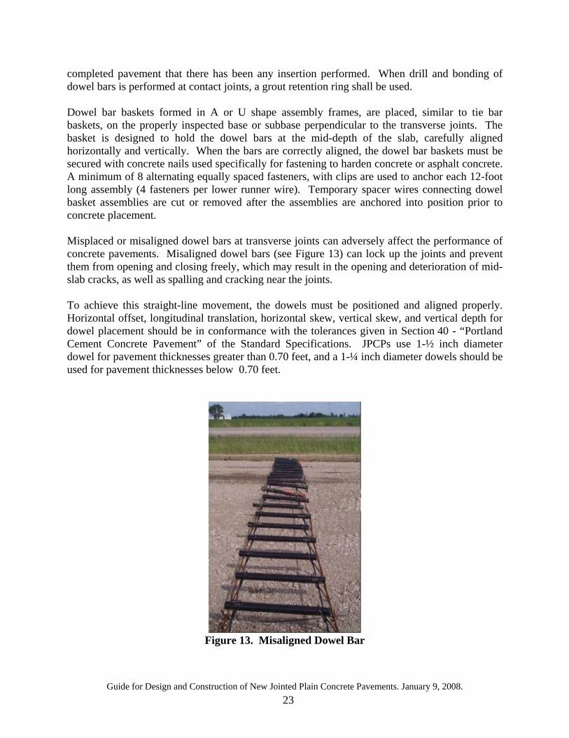
completed pavement that there has been any insertion performed. When drill and bonding of dowel bars is performed at contact joints, a grout retention ring shall be used. Dowel bar baskets formed in A or U shape assembly frames, are placed, similar to tie bar baskets, on the properly inspected base or subbase perpendicular to the transverse joints. The basket is designed to hold the dowel bars at the mid-depth of the slab, carefully aligned horizontally and vertically. When the bars are correctly aligned, the dowel bar baskets must be secured with concrete nails used specifically for fastening to harden concrete or asphalt concrete. A minimum of 8 alternating equally spaced fasteners, with clips are used to anchor each 12-foot long assembly (4 fasteners per lower runner wire). Temporary spacer wires connecting dowel basket assemblies are cut or removed after the assemblies are anchored into position prior to concrete placement. Misplaced or misaligned dowel bars at transverse joints can adversely affect the performance of concrete pavements. Misaligned dowel bars (see Figure 13) can lock up the joints and prevent them from opening and closing freely, which may result in the opening and deterioration of mid-slab cracks, as well as spalling and cracking near the joints. To achieve this straight-line movement, the dowels must be positioned and aligned properly. Horizontal offset, longitudinal translation, horizontal skew, vertical skew, and vertical depth for dowel placement should be in conformance with the tolerances given in Section 40 - “Portland Cement Concrete Pavement” of the Standard Specifications. JPCPs use 1-½ inch diameter dowel for pavement thicknesses greater than 0.70 feet, and a 1-¼ inch diameter dowels should be used for pavement thicknesses below 0.70 feet.
Figure 13. Misaligned Dowel Bar
Guide for Design and Construction of New Jointed Plain Concrete Pavements. January 9, 2008. 24
9.2.3 Bar Reinforcement Placement Although JPCP does not typically have bar reinforcement, bar reinforcement can be found in a few situations such as pavement transitions (Standard Plan P-30), gore areas (Standard Plan P-35), and around drainage inlets (Standard Plans P-45 to P-46). Where bar reinforcement is present it should be placed consistent with the requirements in Section 52 of the Standard Specifications and the special provisions. The reinforcement should be inspected prior to placement of concrete to be sure that it is anchored to prevent it from “floating up” when concrete is placed and that the minimum spacing between bars and clearances to the edge of concrete are met. Bars should also be checked to ensure they are securely tied to each other and will not separate when concrete is placed. 9.3 Concrete Placement To ensure that the concrete used meets or exceeds the specification requirements, a mix design is performed so that proper proportion of its components (cement, aggregates, water) is determined to achieve the specified properties (strength, air content, slump and coefficient of thermal expansion). Concrete is transported to the paving site by dump trucks or ready-mix trucks with the goal to deliver a uniform, well-mixed and workable concrete from batch to batch. The transport method and time delivery affect the workability of the concrete. Delays in concrete deliveries make it necessary to shut down the paving operation and construct a header joint. The placement of concrete in JPCP can be done using any equipment or procedure. Delivery trucks should not be driven on the subbase that would cause differential compaction, therefore, an area must be provided alongside for trucks to deliver the concrete. Consolidation, finishing, curing, and jointing processes follow concrete placement, and they are briefly described below along with SSPs where additional guidance could be found: • Consolidation: it is the process that compacts fresh concrete to mold it within the forms and
around steel reinforcements and to remove undesirable voids. The consolidation requirement can be found in SSP 40-1.07A.
• Finishing: it involves any equipment or procedures used to impart desirable surface characteristics. The preliminary and final finishing requirements can be found in SSP 40-1.09 and 40-110.
• Curing: it is the maintenance of satisfactory moisture and temperature in the concrete as it sets and hardens such that the desired properties can develop. The curing requirement can be found in SSP 90-7.02.
10.0 MAKING JOINTS 10.1 Saw Cutting Joints are formed by saw cutting of concrete at the right time to a pre-specified depth within the slab. The crack forms below the bottom of the saw cut. Currently, the Contractor is given the option for selecting either a single pass or double pass saw cuts. Districts have the option of removing either the single pass saw cut or double saw cut as an option. The double saw cut creates a solid shelf area that provides good support for placement of joint seal backer rod.. The double saw cut is more labor intensive, but ensures crack control by allowing the initial
Guide for Design and Construction of New Jointed Plain Concrete Pavements. January 9, 2008. 25
shrinkage control saw cutting to proceed at a higher production rate and coming back to place the wider reservoir. The single pass procedure is advantageous for the contractor because they only make one saw cut, thus saving time and labor. Saw-cut joints (single pass or double pass) should be sealed, as explained below in Section 10.2, to prevent moisture and incompressible materials from getting into the joint. Timing is a key factor in sawing concrete pavement and should be done as soon as the concrete is capable to support the weight of the sawing equipment. Refer to Caltrans Standard Specification 40-1.08B(1) – “Sawing Method” for additional guidance. To ensure that the transverse joints are sawed across the dowel bar assembly, the dowel centers (mid length points) are located and marked on both sides of the roadbed with either setting pins or paint marks to indicate where pavement joints will be sawed. As a final check, dowel bar positions should be checked to make sure that • all dowel bars are parallel to the centerline, • all dowels are level and the basket assemblies are parallel to and aligned with each other, and • the middle of the dowels falls along the line of set pins or painted marks on one side to the
pin or mark to the other side. Dowel bar baskets should also be checked for spacing, alignment and skew before placing concrete.
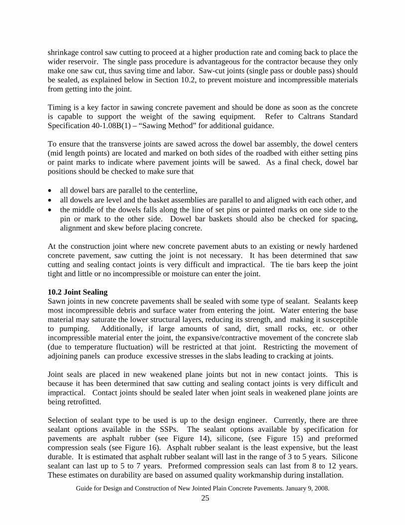
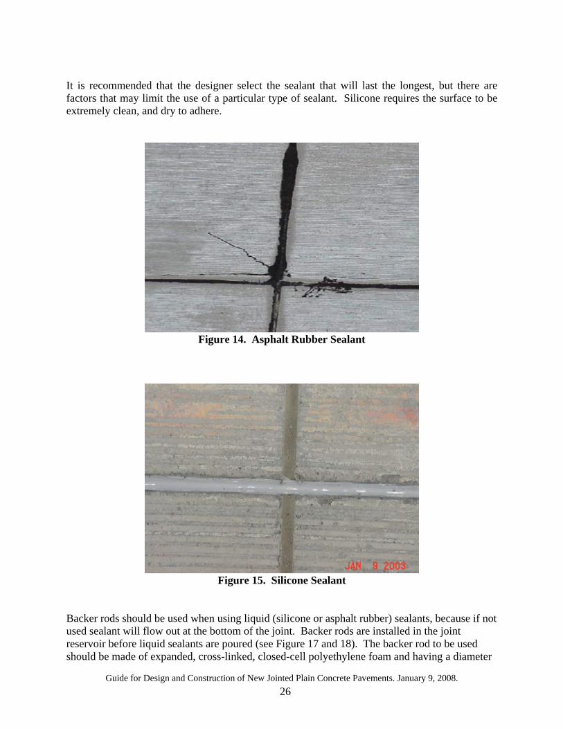
At the construction joint where new concrete pavement abuts to an existing or newly hardened concrete pavement, saw cutting the joint is not necessary. It has been determined that saw cutting and sealing contact joints is very difficult and impractical. The tie bars keep the joint tight and little or no incompressible or moisture can enter the joint. 10.2 Joint Sealing Sawn joints in new concrete pavements shall be sealed with some type of sealant. Sealants keep most incompressible debris and surface water from entering the joint. Water entering the base material may saturate the lower structural layers, reducing its strength, and making it susceptible to pumping. Additionally, if large amounts of sand, dirt, small rocks, etc. or other incompressible material enter the joint, the expansive/contractive movement of the concrete slab (due to temperature fluctuation) will be restricted at that joint. Restricting the movement of adjoining panels can produce excessive stresses in the slabs leading to cracking at joints. Joint seals are placed in new weakened plane joints but not in new contact joints. This is because it has been determined that saw cutting and sealing contact joints is very difficult and impractical. Contact joints should be sealed later when joint seals in weakened plane joints are being retrofitted. Selection of sealant type to be used is up to the design engineer. Currently, there are three sealant options available in the SSPs. The sealant options available by specification for pavements are asphalt rubber (see Figure 14), silicone, (see Figure 15) and preformed compression seals (see Figure 16). Asphalt rubber sealant is the least expensive, but the least durable. It is estimated that asphalt rubber sealant will last in the range of 3 to 5 years. Silicone sealant can last up to 5 to 7 years. Preformed compression seals can last from 8 to 12 years. These estimates on durability are based on assumed quality workmanship during installation.
Guide for Design and Construction of New Jointed Plain Concrete Pavements. January 9, 2008. 26
It is recommended that the designer select the sealant that will last the longest, but there are factors that may limit the use of a particular type of sealant. Silicone requires the surface to be extremely clean, and dry to adhere.
Figure 14. Asphalt Rubber Sealant
Figure 15. Silicone Sealant
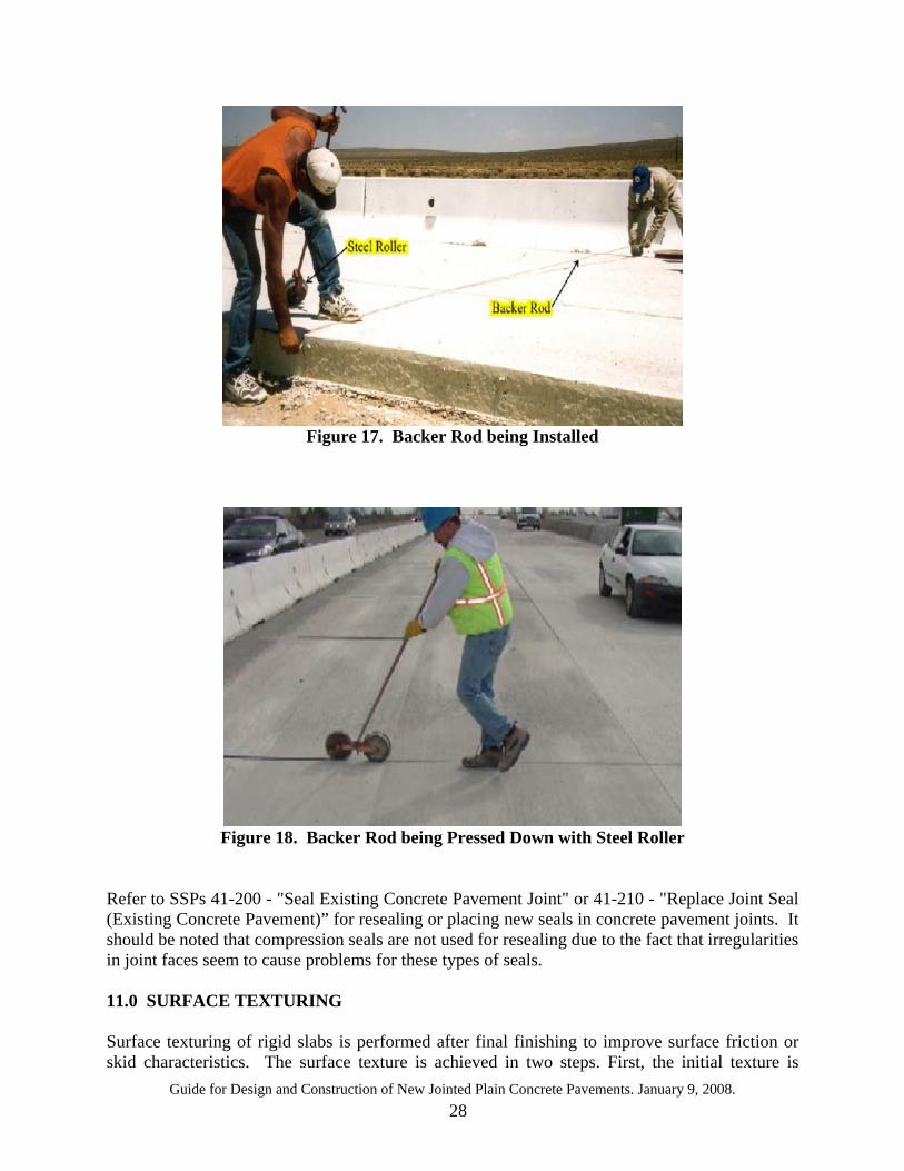
Backer rods should be used when using liquid (silicone or asphalt rubber) sealants, because if not used sealant will flow out at the bottom of the joint. Backer rods are installed in the joint reservoir before liquid sealants are poured (see Figure 17 and 18). The backer rod to be used should be made of expanded, cross-linked, closed-cell polyethylene foam and having a diameter
Guide for Design and Construction of New Jointed Plain Concrete Pavements. January 9, 2008. 27
of at least 25 percent greater than the sawcut joint width. It is to be ensured that no bond or adverse reaction will occur between the backer rod and the sealant.
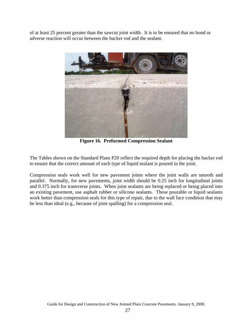
Figure 16. Preformed Compression Sealant
The Tables shown on the Standard Plans P20 reflect the required depth for placing the backer rod to ensure that the correct amount of each type of liquid sealant is poured in the joint. Compression seals work well for new pavement joints where the joint walls are smooth and parallel. Normally, for new pavements, joint width should be 0.25 inch for longitudinal joints and 0.375 inch for transverse joints. When joint sealants are being replaced or being placed into an existing pavement, use asphalt rubber or silicone sealants. These pourable or liquid sealants work better than compression seals for this type of repair, due to the wall face condition that may be less than ideal (e.g., because of joint spalling) for a compression seal.
Guide for Design and Construction of New Jointed Plain Concrete Pavements. January 9, 2008. 28
Figure 17. Backer Rod being Installed
Figure 18. Backer Rod being Pressed Down with Steel Roller
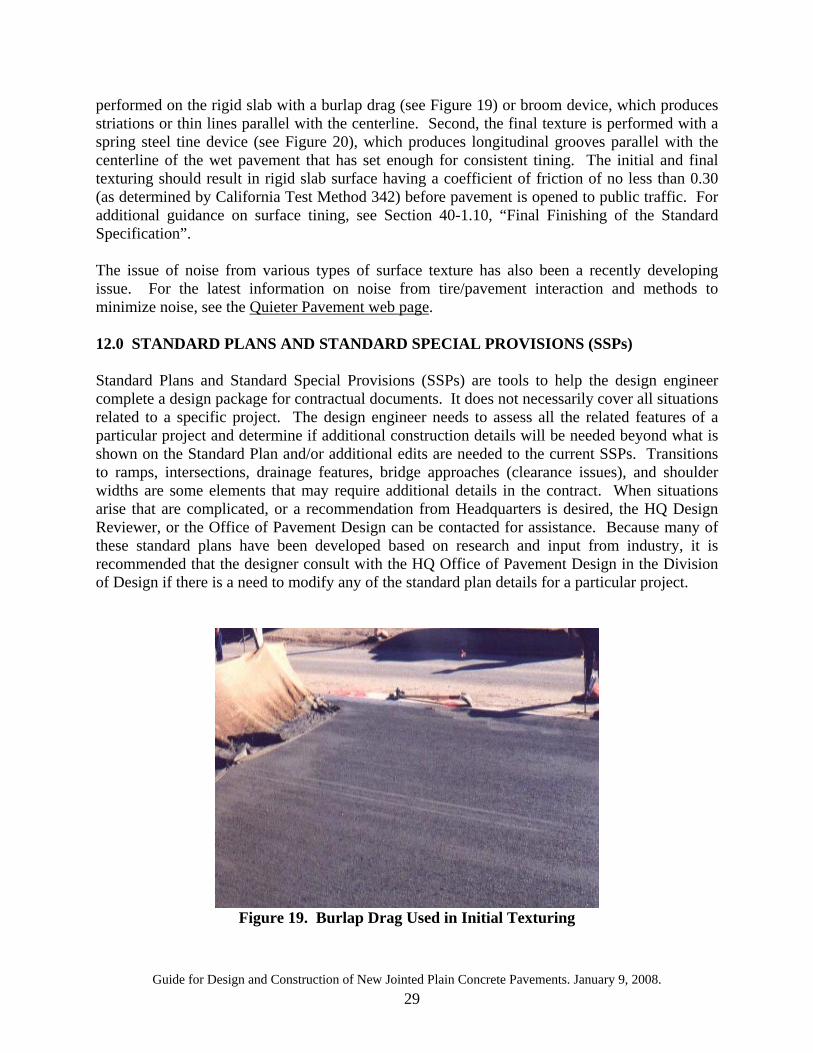
Refer to SSPs 41-200 - "Seal Existing Concrete Pavement Joint" or 41-210 - "Replace Joint Seal (Existing Concrete Pavement)” for resealing or placing new seals in concrete pavement joints. It should be noted that compression seals are not used for resealing due to the fact that irregularities in joint faces seem to cause problems for these types of seals. 11.0 SURFACE TEXTURING Surface texturing of rigid slabs is performed after final finishing to improve surface friction or skid characteristics. The surface texture is achieved in two steps. First, the initial texture is
Guide for Design and Construction of New Jointed Plain Concrete Pavements. January 9, 2008. 29
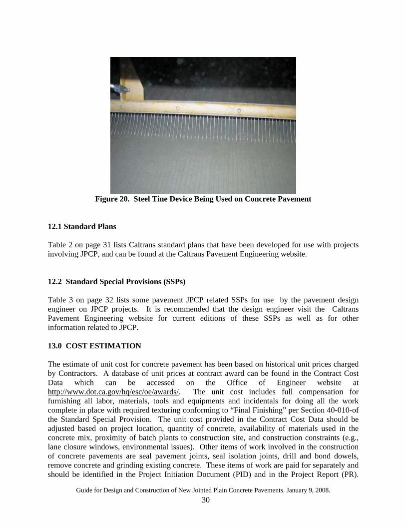
performed on the rigid slab with a burlap drag (see Figure 19) or broom device, which produces striations or thin lines parallel with the centerline. Second, the final texture is performed with a spring steel tine device (see Figure 20), which produces longitudinal grooves parallel with the centerline of the wet pavement that has set enough for consistent tining. The initial and final texturing should result in rigid slab surface having a coefficient of friction of no less than 0.30 (as determined by California Test Method 342) before pavement is opened to public traffic. For additional guidance on surface tining, see Section 40-1.10, “Final Finishing of the Standard Specification”. The issue of noise from various types of surface texture has also been a recently developing issue. For the latest information on noise from tire/pavement interaction and methods to minimize noise, see the Quieter Pavement web page. 12.0 STANDARD PLANS AND STANDARD SPECIAL PROVISIONS (SSPs) Standard Plans and Standard Special Provisions (SSPs) are tools to help the design engineer complete a design package for contractual documents. It does not necessarily cover all situations related to a specific project. The design engineer needs to assess all the related features of a particular project and determine if additional construction details will be needed beyond what is shown on the Standard Plan and/or additional edits are needed to the current SSPs. Transitions to ramps, intersections, drainage features, bridge approaches (clearance issues), and shoulder widths are some elements that may require additional details in the contract. When situations arise that are complicated, or a recommendation from Headquarters is desired, the HQ Design Reviewer, or the Office of Pavement Design can be contacted for assistance. Because many of these standard plans have been developed based on research and input from industry, it is recommended that the designer consult with the HQ Office of Pavement Design in the Division of Design if there is a need to modify any of the standard plan details for a particular project.
Figure 19. Burlap Drag Used in Initial Texturing
Guide for Design and Construction of New Jointed Plain Concrete Pavements. January 9, 2008. 30
Figure 20. Steel Tine Device Being Used on Concrete Pavement
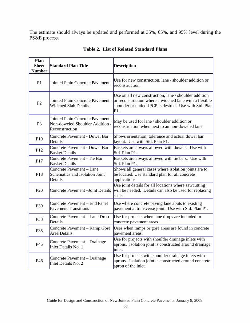
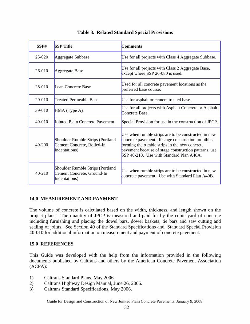
12.1 Standard Plans Table 2 on page 31 lists Caltrans standard plans that have been developed for use with projects involving JPCP, and can be found at the Caltrans Pavement Engineering website. 12.2 Standard Special Provisions (SSPs) Table 3 on page 32 lists some pavement JPCP related SSPs for use by the pavement design engineer on JPCP projects. It is recommended that the design engineer visit the Caltrans Pavement Engineering website for current editions of these SSPs as well as for other information related to JPCP. 13.0 COST ESTIMATION The estimate of unit cost for concrete pavement has been based on historical unit prices charged by Contractors. A database of unit prices at contract award can be found in the Contract Cost Data which can be accessed on the Office of Engineer website at http://www.dot.ca.gov/hq/esc/oe/awards/. The unit cost includes full compensation for furnishing all labor, materials, tools and equipments and incidentals for doing all the work complete in place with required texturing conforming to “Final Finishing” per Section 40-010-of the Standard Special Provision. The unit cost provided in the Contract Cost Data should be adjusted based on project location, quantity of concrete, availability of materials used in the concrete mix, proximity of batch plants to construction site, and construction constraints (e.g., lane closure windows, environmental issues). Other items of work involved in the construction of concrete pavements are seal pavement joints, seal isolation joints, drill and bond dowels, remove concrete and grinding existing concrete. These items of work are paid for separately and should be identified in the Project Initiation Document (PID) and in the Project Report (PR).
Guide for Design and Construction of New Jointed Plain Concrete Pavements. January 9, 2008. 31
The estimate should always be updated and performed at 35%, 65%, and 95% level during the PS&E process.
Table 2. List of Related Standard Plans
Plan Sheet
Number Standard Plan Title Description
P1 Jointed Plain Concrete Pavement Use for new construction, lane / shoulder addition or reconstruction.
P2 Jointed Plain Concrete Pavement - Widened Slab Details
Use on all new construction, lane / shoulder addition or reconstruction where a widened lane with a flexible shoulder or untied JPCP is desired. Use with Std. Plan P1.
P3 Jointed Plain Concrete Pavement –Non-doweled Shoulder Addition / Reconstruction
May be used for lane / shoulder addition or reconstruction when next to an non-doweled lane
P10 Concrete Pavement - Dowel Bar Details
Shows orientation, tolerance and actual dowel bar layout. Use with Std. Plan P1.
P12 Concrete Pavement - Dowel Bar Basket Details
Baskets are always allowed with dowels. Use with Std. Plan P1.
P17 Concrete Pavement - Tie Bar Basket Details
Baskets are always allowed with tie bars. Use with Std. Plan P1.
P18 Concrete Pavement – Lane Schematics and Isolation Joint Details
Shows all general cases where isolation joints are to be located. Use standard plan for all concrete applications
P20 Concrete Pavement –Joint Details Use joint details for all locations where sawcutting will be needed. Details can also be used for replacing seals.
P30 Concrete Pavement – End Panel Pavement Transitions
Use where concrete paving lane abuts to existing pavement at transverse joint. Use with Std. Plan P1.
P33 Concrete Pavement – Lane Drop Details
Use for projects when lane drops are included in concrete pavement areas.
P35 Concrete Pavement – Ramp Gore Area Details
Uses when ramps or gore areas are found in concrete pavement areas.
P45 Concrete Pavement – Drainage Inlet Details No. 1
Use for projects with shoulder drainage inlets with aprons. Isolation joint is constructed around drainage inlet.
P46 Concrete Pavement – Drainage Inlet Details No. 2
Use for projects with shoulder drainage inlets with aprons. Isolation joint is constructed around concrete apron of the inlet.
Guide for Design and Construction of New Jointed Plain Concrete Pavements. January 9, 2008. 32
Table 3. Related Standard Special Provisions
SSP# SSP Title Comments
25-020 Aggregate Subbase Use for all projects with Class 4 Aggregate Subbase.
26-010 Aggregate Base Use for all projects with Class 2 Aggregate Base, except where SSP 26-080 is used.
28-010 Lean Concrete Base Used for all concrete pavement locations as the preferred base course.
29-010 Treated Permeable Base Use for asphalt or cement treated base.
39-010 HMA (Type A) Use for all projects with Asphalt Concrete or Asphalt Concrete Base.
40-010 Jointed Plain Concrete Pavement Special Provision for use in the construction of JPCP.
40-200 Shoulder Rumble Strips (Portland Cement Concrete, Rolled-In Indentations)
Use when rumble strips are to be constructed in new concrete pavement. If stage construction prohibits forming the rumble strips in the new concrete pavement because of stage construction patterns, use SSP 40-210. Use with Standard Plan A40A.
40-210 Shoulder Rumble Strips (Portland Cement Concrete, Ground-In Indentations)
Use when rumble strips are to be constructed in new concrete pavement. Use with Standard Plan A40B.
14.0 MEASUREMENT AND PAYMENT The volume of concrete is calculated based on the width, thickness, and length shown on the project plans. The quantity of JPCP is measured and paid for by the cubic yard of concrete including furnishing and placing the dowel bars, dowel baskets, tie bars and saw cutting and sealing of joints. See Section 40 of the Standard Specifications and Standard Special Provision 40-010 for additional information on measurement and payment of concrete pavement. 15.0 REFERENCES This Guide was developed with the help from the information provided in the following documents published by Caltrans and others by the American Concrete Pavement Association (ACPA): 1) Caltrans Standard Plans, May 2006. 2) Caltrans Highway Design Manual, June 26, 2006. 3) Caltrans Standard Specifications, May 2006.

Guide for Design and Construction of New Jointed Plain Concrete Pavements. January 9, 2008. 33
4) PCC Frequently Asked Questions that can be found at Caltrans Pavement Engineering website.
5) Bulletins published by the American Concrete Pavement Association:
• Design and Construction of Joints for Concrete Highways. • Concrete Intersections - A Guide for Design & Construction. • Intersection Joint Layout. • Proper Use of Isolation and Expansion Joints in Concrete Pavements.
16.0 QUESTIONS AND COMMENTS Occasionally, questions or comments may arise: • Design-related questions and comments should be directed to the Pavement Design &
Analysis Branch, Office of Pavement Design. • Construction-related questions and comments should be directed to the Office of
Construction Standards. • Materials-related questions and comments should be directed to Materials Engineering and
Testing Services (METS), Office of Rigid Pavement Materials and Structural Concrete. • General comments about this Guide may be directed to the authors of this Guide: Flor
Bautista and Imad Basheer.


