GENERAL Units shall be performance certified to ISO standard 13256-1 for Water Loop Heat Pump, Ground Water Heat Pump and Ground Loop Heat Pump applications. Units shall be Underwriter Laboratories (UL and ULc) listed for safety on all models. Each unit shall be run tested at the factory. Each unit shall be pallet mounted and stretch wrapped. The units shall be manufactured in an ISO9001:2000 certified facil- ity. The units shall be warranted by the manufacturer against defects in materials and workmanship for a period of i) in the case of residentially sold units having the last digit of the serial number as a 'T'; five years on all parts and 10 years on the refrigerant circuit components ii) on all other units; five years on the compressor and one year on all other parts. The units shall be designed to operate with entering fluid temperatures between 50 o F (10 o C) and 110 o F (43.3 o C) in cooling and temperatures between 20 o F (-6.6 o C) and 80 o F (27 o C) in heating as manu- factured by FHP Manufacturing in Fort Lauderdale, Florida. CASING & CABINET The cabinet shall be fabricated from heavy-gauge steel finished with a vinyl coated black cabinet and decorative gold anodized aluminum front panel for corrosion protection. The interior shall be insulated with ½” (12.7mm) thick foil faced glass fiber. All units shall allow sufficient service access to replace the compressor without unit removal. One blower and two compressor compartment access panels shall be re- movable with supply and return ductwork in place. A duct collar shall be provided on the supply air opening. A filter rack with 2" (50.8 mm) thick disposable filters and a 1" (25.4mm) return air duct collar shall be pro- vided with each unit. Air filters shall be MERV 11 rated. The units shall have an insulated divider panel between the air handling section and the compressor section to minimize the transmission of compressor noise, and to permit service testing without air bypass. Units shall have a stain- less steel condensate drain pan. The compressor shall have a floating base pan to minimize noise transmissions. REFRIGERATION CIRCUITS All units shall contain a sealed refrigerant circuit including a two stage scroll compressor, bi-directional thermal expansion valve metering device, finned tube air-to-refrigerant heat exchanger, refrigerant reversing valve and service ports. Compressor shall be high efficiency two stage scroll type, designed for heat pump duty, quiet operation and mounted on rubber vibration isolators. Compressor motors shall be equipped with overload protection. Refrigerant reversing valves shall be pilot operated sliding piston type with replaceable encapsulated magnetic coils energized only during the cooling cycle. The finned tube coil shall be constructed of lanced aluminum fins not exceeding fourteen fins per inch bonded to rifled copper tubes in a staggered pattern not less than three rows deep and have a 450 PSIG (3100 kPa) working pres- sure. Coils shall have a baked polyester enamel coating for protection against most airborne chemicals. Coil end plates shall be aluminum. The coaxial water-to-refrigerant heat exchanger shall be constructed of a convoluted copper (optional cupronickel) inner tube and steel outer tube with a designed refrigerant working pressure of 450 PSIG (3100 kPa) and a designed water side working pressure of no less than 400 PSIG (2750 kPa). The water-to-refrigerant heat exchanger shall be insu- lated to prevent condensation at low fluid temperatures. FAN MOTOR & ASSEMBLY APSPECS.P65 REV: 1-08 GUIDE SPECIFICATIONS AQUARIUS II AP Series Two Stage R-410A the fan motor.The fan motor shall be an ECM-2 microprocessor controlled DC type motor with internal programming factory set for the specific unit and featuring soft start/stop and a delay off feature for maximum effi- ciency and quiet operation. Air flow rates shall be varied according to the staging of the unit. There will further be provisions for adjusting the air delivery of the motor and blower by +/- 15% from rated air flow. ELECTRICAL Controls and safety devices will be factory wired and mounted within the unit. Controls shall include comfort alert module, compressor contactor, 24V transformer, reversing valve coil and solid state lock-out controller (UPM). The UPM controller shall include the following features: diagnostic LED's, low pressure bypass time delay (to prevent nuisance low pressure lock-outs during operation with low fluid temperatures), anti short cycle time delay, random start time delay and one time intelligent reset. When the safety controls are activated the lock-out circuit shall reset itself the first time. If the safety controls are subsequently activated within one hour, then the lock-out circuit shall disable the compressor until it is reset at the thermostat or main circuit breaker to prevent compressor operation during fault conditions. A lock-out indicating terminal shall be provided in the low voltage circuit. Safety devices include a low pressure cutout set a 40 PSIG (280 kPa) for loss of charge protection (freezestat and/or high dis- charge gas temperature sensor is not acceptable) and a high pressure cutout control set at 600 PSIG (4100 kPa). The ECM motor interface board shall provide a screw type terminal block for thermostat connection, LED's to indicate thermostat status and air delivery. It shall also provide a means of changing the motor program to any of up to four pre-programmed options. Direct wiring of the motor control harness to the thermostat is not acceptable. A terminal block with screw terminals shall be provided for control wiring. An optional condensate overflow device shall be factory installed to stop compressor operation if drain pan overflow is imminent. An optional energy management relay to allow unit control by an external source shall be factory installed. PIPING Supply, return water and condensate drain connections shall be brass female pipe thread fittings and mounted flush to cabinet exterior. INTERNAL ELECTRIC HEAT 208/230-1-60 volt units shall be equipped with optional factory installed internal electric resistance heat for auxiliary and emergency heat. Electric heater must be Underwriter's Laboratories (UL and ULc) approved for safety when installed in the unit. External heater packages or heater packages not specifically listed for use with the unit are unacceptable. Electric heater packages shall include a heater collar mounted to the blower outlet, individual thermal overload protected heater elements no greater than 5kW each and magnetic contactors. Heater packages shall have a separate power supply connection from the compressor and this power supply shall also power the unit blower motor and control transformer for safe operation. HEAT RECOVERY PACKAGE 208/230 volt units shall be equipped with an optional factory installed internal heat recovery kit for domestic hot water production. This kit shall include an internally protected pump, double walled coaxial water-to-refrigerant heat exchanger, 140 o F (60 o C) hot wa- ter temperature limit switch and an on/off switch/circuit breaker. The fan shall be direct drive centrifugal forward curved type with a the unit without disconnecting the supply air ductwork for servicing of dynamically balanced wheel. The housing and wheel shall be designed for quiet low velocity operation. The fan housing shall be removable from
Transcript
GENERALUnits shall be performance certified to ISO standard13256-1 for Water Loop Heat Pump, Ground Water Heat Pump and GroundLoop Heat Pump applications. Units shall be Underwriter Laboratories(UL and ULc) listed for safety on all models. Each unit shall be run testedat the factory. Each unit shall be pallet mounted and stretch wrapped.The units shall be manufactured in an ISO9001:2000 certified facil-ity.
The units shall be warranted by the manufacturer againstdefects in materials and workmanship for a period of i) in the case ofresidentially sold units having the last digit of the serial number as a 'T';five years on all parts and 10 years on the refrigerant circuit componentsii) on all other units; five years on the compressor and one year on allother parts.
The units shall be designed to operate with entering fluidtemperatures between 50oF (10oC) and 110oF (43.3oC) in cooling andtemperatures between 20oF (-6.6oC) and 80oF (27oC) in heating as manu-factured by FHP Manufacturing in Fort Lauderdale, Florida.
CASING & CABINETThe cabinet shall be fabricated from heavy-gauge steel finished with avinyl coated black cabinet and decorative gold anodized aluminumfront panel for corrosion protection. The interior shall be insulatedwith ½” (12.7mm) thick foil faced glass fiber. All units shall allow sufficientservice access to replace the compressor without unit removal. Oneblower and two compressor compartment access panels shall be re-movable with supply and return ductwork in place. A duct collar shall beprovided on the supply air opening. A filter rack with 2" (50.8 mm) thickdisposable filters and a 1" (25.4mm) return air duct collar shall be pro-vided with each unit. Air filters shall be MERV 11 rated. The units shallhave an insulated divider panel between the air handling section and thecompressor section to minimize the transmission of compressor noise,and to permit service testing without air bypass. Units shall have a stain-less steel condensate drain pan. The compressor shall have a floatingbase pan to minimize noise transmissions.
REFRIGERATION CIRCUITSAll units shall contain a sealed refrigerant circuit including a two stagescroll compressor, bi-directional thermal expansion valvemetering device, finned tube air-to-refrigerant heat exchanger,refrigerant reversing valve and service ports. Compressor shall be highefficiency two stage scroll type, designed for heat pump duty, quietoperation and mounted on rubber vibration isolators. Compressor motorsshall be equipped with overload protection. Refrigerant reversing valvesshall be pilot operated sliding piston type with replaceable encapsulatedmagnetic coils energized only during the cooling cycle. The finned tubecoil shall be constructed of lanced aluminum fins not exceeding fourteenfins per inch bonded to rifled copper tubes in a staggered pattern not lessthan three rows deep and have a 450 PSIG (3100 kPa) working pres-sure. Coils shall have a baked polyester enamel coating for protectionagainst most airborne chemicals. Coil end plates shall be aluminum.The coaxial water-to-refrigerant heat exchanger shall be constructed ofa convoluted copper (optional cupronickel) inner tube and steel outertube with a designed refrigerant working pressure of 450 PSIG (3100kPa) and a designed water side working pressure of no less than 400PSIG (2750 kPa). The water-to-refrigerant heat exchanger shall be insu-lated to prevent condensation at low fluid temperatures.
FAN MOTOR & ASSEMBLY
APSPECS.P65 REV: 1-08
GUIDESPECIFICATIONS
AQUARIUS IIAP Series Two Stage R-410A
the fan motor.The fan motor shall be an ECM-2 microprocessor controlledDC type motor with internal programming factory set for the specific unitand featuring soft start/stop and a delay off feature for maximum effi-ciency and quiet operation. Air flow rates shall be varied according to thestaging of the unit. There will further be provisions for adjusting the airdelivery of the motor and blower by +/- 15% from rated air flow.
ELECTRICALControls and safety devices will be factory wired and mounted within theunit. Controls shall include comfort alert module, compressor contactor,24V transformer, reversing valve coil and solid state lock-out controller(UPM). The UPM controller shall include the following features: diagnosticLED's, low pressure bypass time delay (to prevent nuisance low pressurelock-outs during operation with low fluid temperatures), anti short cycletime delay, random start time delay and one time intelligent reset. When thesafety controls are activated the lock-out circuit shall reset itself the firsttime. If the safety controls are subsequently activated within one hour,then the lock-out circuit shall disable the compressor until it is reset at thethermostat or main circuit breaker to prevent compressor operation duringfault conditions. A lock-out indicating terminal shall be provided in the lowvoltage circuit. Safety devices include a low pressure cutout set a 40PSIG (280 kPa) for loss of charge protection (freezestat and/or high dis-charge gas temperature sensor is not acceptable) and a high pressurecutout control set at 600 PSIG (4100 kPa).The ECM motor interface board shall provide a screw type terminal blockfor thermostat connection, LED's to indicate thermostat status and airdelivery. It shall also provide a means of changing the motor program to anyof up to four pre-programmed options. Direct wiring of the motor controlharness to the thermostat is not acceptable.
A terminal block with screw terminals shall be provided for control wiring.An optional condensate overflow device shall be factoryinstalled to stop compressor operation if drain pan overflow isimminent. An optional energy management relay to allow unit control by anexternal source shall be factory installed.
PIPINGSupply, return water and condensate drain connections shall be brassfemale pipe thread fittings and mounted flush to cabinetexterior.
INTERNAL ELECTRIC HEAT208/230-1-60 volt units shall be equipped with optional factoryinstalled internal electric resistance heat for auxiliary andemergency heat. Electric heater must be Underwriter's Laboratories (ULand ULc) approved for safety when installed in the unit. External heaterpackages or heater packages not specifically listed for use with the unitare unacceptable. Electric heater packages shall include a heater collarmounted to the blower outlet, individual thermal overload protected heaterelements no greater than 5kW each and magnetic contactors. Heaterpackages shall have a separate power supply connection from thecompressor and this power supply shall also power the unit blower motorand control transformer for safe operation.
HEAT RECOVERY PACKAGE208/230 volt units shall be equipped with an optional factoryinstalled internal heat recovery kit for domestic hot waterproduction. This kit shall include an internally protected pump, doublewalled coaxial water-to-refrigerant heat exchanger, 140oF (60oC) hot wa-ter temperature limit switch and an on/off switch/circuit breaker.
The fan shall be direct drive centrifugal forward curved type with a
the unit without disconnecting the supply air ductwork for servicing of
dynamically balanced wheel. The housing and wheel shall be designedfor quiet low velocity operation. The fan housing shall be removable from
Right HandReturn(FRT)
NOTES: All dimensions within +/- 0.125".All condensate drain connections are 3/4" FPT.All Heat Recovery Kit connections are 1/2" FPT.Internal electric heat available on 208-230/1/60 top discharge units onlyInternal Heat Recovery Kit available on 208-230 volt units only.Specifications subject to change without notice.
AP AP AP AP AP TTTTTwwwwwo Stao Stao Stao Stao Staggggge Seriese Seriese Seriese Seriese Series VVVVVererererertical Dimensionstical Dimensionstical Dimensionstical Dimensionstical Dimensions
A B C D E F G H J K M N P Q Condenser RecommendedMODEL R/A Duct R/A Duct Filter Rack Water Replacement
NOTES: All dimensions within +/- 0.125".All condensate drain connections are 3/4" FPT.All Heat Recovery connections are 1/2" FPT.Internal electric heat available on 208-230 volt units onlyInternal Loop Pump available on 208-230 volt units only.Internal Heat Recovery Kit available on 208-230 volt units only.Units can be field converted between end blow and straight through supply air configurations.Specifications subject to change without notice.
AP AP AP AP AP TTTTTwwwwwo Stao Stao Stao Stao Staggggge Seriese Seriese Seriese Seriese Series Horizontal Dimensions Horizontal Dimensions Horizontal Dimensions Horizontal Dimensions Horizontal Dimensions
D
E
F
HG
C
B
AccessPanel
ElectricalKnock-outs
HeaterKnock-out
Return AirOpening
CondensateDrain
A
JK
M
N
C
B
Return AirOpening
A
QK
PNCondensate
Drain
AB
CondensateDrain
Return AirOpening
MK
P
C
N
AB
NCondensate
Drain
HeaterKnock-out
JK
Q
Return AirOpening
C
AccessPanel
CondenserWater Out
CondenserWater In
D
E
FHRP
A B C D E F G H J K M N P Condenser RecommendedMODEL Blower Blower R/A Duct R/A Duct Filter Rack Water Replacement
AP AP AP AP AP TTTTTwwwwwo Stao Stao Stao Stao Staggggge Seriese Seriese Seriese Seriese Series Counterf Counterf Counterf Counterf Counterflololololow Dimensionsw Dimensionsw Dimensionsw Dimensionsw Dimensions
NOTES: All dimensions within +/- 0.125".All condensate drain connections are 3/4" FPT.All Heat Recovery Kit connections are 1/2" FPT.Internal electric heat available on 208-230/1/60 bottom discharge units onlyInternal Loop Pump available on 208-230 volt units only.Internal Heat Recovery Kit available on 208-230 volt units only.Specifications subject to change without notice.APCFDGIP INT II.P65 REV: 1-08
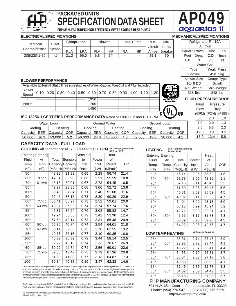
Units are complete packages containing compressor, reversing valve, expansion valve metering device, ECM fan motorand heat exchangers. Also included are safety controls: Overload protection for motors, high and low refrigerantpressure switches and solid state lock-out circuit. Optional UL approved internal electric heater, factory installed withprimary thermal overload protection and magnetic contactors (208/230-1-60 only) optional UL approved internal HeatRecovery Package and/or Ground Loop Pump with purge connections available
Performance based on ARI/ISO rated air flow, fluid flow and voltage. For conditions other than rated, consult the FHPEAD selection software. Due to variations in installation actual performance may vary marginally from tabulated values.
As a result of continuing research and development, specifications are subject to change without notice.AP025.1IP60 Rev: 1-08
Units are complete packages containing compressor, reversing valve, expansion valve metering device, ECM fan motorand heat exchangers. Also included are safety controls: Overload protection for motors, high and low refrigerantpressure switches and solid state lock-out circuit. Optional UL approved internal electric heater, factory installed withprimary thermal overload protection and magnetic contactors (208/230-1-60 only) optional UL approved internal HeatRecovery Package and/or Ground Loop Pump with purge connections available
Performance based on ARI/ISO rated air flow, fluid flow and voltage. For conditions other than rated, consult the FHPEAD selection software. Due to variations in installation actual performance may vary marginally from tabulated values.
As a result of continuing research and development, specifications are subject to change without notice.AP025.2IP60 Rev: 1-08
Units are complete packages containing compressor, reversing valve, expansion valve metering device, ECM fan motorand heat exchangers. Also included are safety controls: Overload protection for motors, high and low refrigerantpressure switches and solid state lock-out circuit. Optional UL approved internal electric heater, factory installed withprimary thermal overload protection and magnetic contactors (208/230-1-60 only) optional UL approved internal HeatRecovery Package and/or Ground Loop Pump with purge connections available
Performance based on ARI/ISO rated air flow, fluid flow and voltage. For conditions other than rated, consult the FHPEAD selection software. Due to variations in installation actual performance may vary marginally from tabulated values.
As a result of continuing research and development, specifications are subject to change without notice.AP035.1IP60 Rev: 1-08
Units are complete packages containing compressor, reversing valve, expansion valve metering device, ECM fan motorand heat exchangers. Also included are safety controls: Overload protection for motors, high and low refrigerantpressure switches and solid state lock-out circuit. Optional UL approved internal electric heater, factory installed withprimary thermal overload protection and magnetic contactors (208/230-1-60 only) optional UL approved internal HeatRecovery Package and/or Ground Loop Pump with purge connections available
Performance based on ARI/ISO rated air flow, fluid flow and voltage. For conditions other than rated, consult the FHPEAD selection software. Due to variations in installation actual performance may vary marginally from tabulated values.
As a result of continuing research and development, specifications are subject to change without notice.AP035.2IP60 Rev: 1-08
Units are complete packages containing compressor, reversing valve, expansion valve metering device, ECM fan motorand heat exchangers. Also included are safety controls: Overload protection for motors, high and low refrigerantpressure switches and solid state lock-out circuit. Optional UL approved internal electric heater, factory installed withprimary thermal overload protection and magnetic contactors (208/230-1-60 only) optional UL approved internal HeatRecovery Package and/or Ground Loop Pump with purge connections available
Performance based on ARI/ISO rated air flow, fluid flow and voltage. For conditions other than rated, consult the FHPEAD selection software. Due to variations in installation actual performance may vary marginally from tabulated values.
As a result of continuing research and development, specifications are subject to change without notice.AP049.1IP60 Rev: 1-08
Units are complete packages containing compressor, reversing valve, expansion valve metering device, ECM fan motorand heat exchangers. Also included are safety controls: Overload protection for motors, high and low refrigerantpressure switches and solid state lock-out circuit. Optional UL approved internal electric heater, factory installed withprimary thermal overload protection and magnetic contactors (208/230-1-60 only) optional UL approved internal HeatRecovery Package and/or Ground Loop Pump with purge connections available
Performance based on ARI/ISO rated air flow, fluid flow and voltage. For conditions other than rated, consult the FHPEAD selection software. Due to variations in installation actual performance may vary marginally from tabulated values.
As a result of continuing research and development, specifications are subject to change without notice.AP049.2IP60 Rev: 1-08
Units are complete packages containing compressor, reversing valve, expansion valve metering device, ECM fan motorand heat exchangers. Also included are safety controls: Overload protection for motors, high and low refrigerantpressure switches and solid state lock-out circuit. Optional UL approved internal electric heater, factory installed withprimary thermal overload protection and magnetic contactors (208/230-1-60 only) optional UL approved internal HeatRecovery Package and/or Ground Loop Pump with purge connections available
Performance based on ARI/ISO rated air flow, fluid flow and voltage. For conditions other than rated, consult the FHPEAD selection software. Due to variations in installation actual performance may vary marginally from tabulated values.
As a result of continuing research and development, specifications are subject to change without notice.AP061.1IP60 Rev: 1-08
Units are complete packages containing compressor, reversing valve, expansion valve metering device, ECM fan motorand heat exchangers. Also included are safety controls: Overload protection for motors, high and low refrigerantpressure switches and solid state lock-out circuit. Optional UL approved internal electric heater, factory installed withprimary thermal overload protection and magnetic contactors (208/230-1-60 only) optional UL approved internal HeatRecovery Package and/or Ground Loop Pump with purge connections available
Performance based on ARI/ISO rated air flow, fluid flow and voltage. For conditions other than rated, consult the FHPEAD selection software. Due to variations in installation actual performance may vary marginally from tabulated values.
As a result of continuing research and development, specifications are subject to change without notice.AP061.2IP60 Rev: 1-08
Units are complete packages containing compressor, reversing valve, expansion valve metering device, ECM fan motorand heat exchangers. Also included are safety controls: Overload protection for motors, high and low refrigerantpressure switches and solid state lock-out circuit. Optional UL approved internal electric heater, factory installed withprimary thermal overload protection and magnetic contactors (208/230-1-60 only) optional UL approved internal HeatRecovery Package and/or Ground Loop Pump with purge connections available
Performance based on ARI/ISO rated air flow, fluid flow and voltage. For conditions other than rated, consult the FHPEAD selection software. Due to variations in installation actual performance may vary marginally from tabulated values.
As a result of continuing research and development, specifications are subject to change without notice.AP071.1IP60 Rev: 1-08
Units are complete packages containing compressor, reversing valve, expansion valve metering device, ECM fan motorand heat exchangers. Also included are safety controls: Overload protection for motors, high and low refrigerantpressure switches and solid state lock-out circuit. Optional UL approved internal electric heater, factory installed withprimary thermal overload protection and magnetic contactors (208/230-1-60 only) optional UL approved internal HeatRecovery Package and/or Ground Loop Pump with purge connections available
Performance based on ARI/ISO rated air flow, fluid flow and voltage. For conditions other than rated, consult the FHPEAD selection software. Due to variations in installation actual performance may vary marginally from tabulated values.
As a result of continuing research and development, specifications are subject to change without notice.AP071.2IP60 Rev: 1-08
SUPPLY AIR LOCATION:T - TOP (VT ONLY)E - END BLOW (HZ ONLY)B - BOTTOM (CF ONLY)
RETURN AIR LOCATION:L - LEFTR - RIGHTB - BACKF - FRONT
WATER CONNECTIONLOCATION:F - FRONT
AP 049 -1 VT C - F L T
INITIAL INSPECTION:
Be certain to inspect all cartons or crates on each unitas received at the job site before signing the freight bill.Verify that all items have been received and that thereare no visible damages; note any shortages ordamages on all copies of the freight bill. In the event ofdamage or shortage, remember that the purchaser isresponsible for filing the necessary claims with thecarrier. Concealed damages not discovered until afterremoving the units from the packaging must bereported to the carrier within 24 hours of receipt.
GENERAL DESCRIPTION:
These Water-to-Air Heat Pumps provide the bestcombination of performance and efficiency available.Safety devices are built into each unit to provide themaximum system protection possible when properlyinstalled and maintained.
The AP Water-to-Air Heat Pumps are UnderwritersLaboratories (UL) and (cUL) listed for safety. The water-to-Air Heat Pumps are designed to operate withentering fluid temperature between 20°F to 80°F in theheating mode and between 50°F to 110°F in thecooling mode.
NOTE: 50°F Min. EWT for well water applications withsufficient water flow to prevent freezing. Antifreezesolution is required for all closed loop applications.Cooling Tower/Boiler and Earth Coupled (Geo Thermal)applications should have sufficient antifreeze solutionto protect against extreme conditions and equipmentfailure. Frozen water coils are not covered underwarranty.
NOTE: This product should not be used fortemporarily heating/cooling during construction. Doingso may effect the units warranty.
MOVING AND STORAGE:
If the equipment is not needed for immediateinstallation upon its arrival at the job site, it should beleft in its shipping carton and stored in a clean, dryarea. Units must only be stored or moved in the normalupright position as indicated by the "UP" arrows oneach carton at all times. If unit stacking is required,stack units as follows: Vertical units less than 6 tons,no more than two high. Horizontal units less than 6tons, no more than three high. "Do not stack unitslarger than 6 tons."
SAFETY CONSIDERATIONS:
Installation and servicing of this equipment can behazardous due to system pressure and electricalcomponents. Only trained and qualified personnelshould install, repair, or service the equipment.Untrained personnel can perform basic functions ofmaintenance such as cleaning coils and replacingfilters.
WARNING: Before performing service ormaintenance operations on the system, turn off mainpower to the unit. Electrical shock could causepersonal injury or death.
When working on equipment, always observeprecautions described in the literature, tags, and labelsattached to the unit. Follow all safety codes. Wearsafety glasses and work gloves. Use a quenching clothfor brazing, and place a fire extinguisher close to thework area.
LOCATION:
Locate the unit in an indoor area that allows easyremoval of the filter and access panels, and hasenough room for service personnel to performmaintenance or repair. Provide sufficient room to makefluid, electrical, and duct connection(s). If the unit islocated in a confined space such as a closet,provisions must be made for return air to freely enterthe space. On horizontal units, allow adequate roombelow the unit for a condensate drain trap and do notlocate the unit above supply piping. These units are notapproved for outdoor installation; therefore, they mustbe installed inside the structure being conditioned. Donot locate in areas that are subject to freezing.
INSTALLATION:
NOTE: Remove all shipping blocks under blowerhousing. Loosen compressor mounting bolts.
MOUNTING VERTICAL UNITS:
Vertical units up tosix tons are availablein left, right, front, orrear air returnc o n f i g u r a t i o n s .Vertical units shouldbe mounted level ona vibration absorbingpad slightly largerthan the base tominimize vibrationtransmission to thebuilding structure. Itis not necessary toanchor the unit to thefloor. (See Figure #1).
MOUNTING HORIZONTAL UNITS:
While horizontal units may be installed on any levelsurface strong enough to hold their weight, they aretypically suspended above a ceiling by threaded rods.The rods are usually attached to the unit corners by
hanger bracket kits(P/N 930-004, 006).(See Figure #2). Therods must be securelyanchored to the ceiling.Refer to the hangingbracket assembly andinstallation instructionsfor details. ModelsAP035 and up require
six brackets (930-006).(See unit horizontal detaildrawing). Horizontal units installed above the ceilingmust conform to all local codes. An auxiliary drain pan
AP SERIES
(Figure #2)
(Figure #1)
VIBRATIONPAD
FULL SIZE
2
if required by code, should be at least four incheslarger than the bottom of the heat pump. Plumbingconnected to the heat pump must not come in directcontact with joists, trusses, walls, etc.
Some applications require an attic floor installation ofthe horizontal unit. In this case the unit should be setin a full size secondary drain pan on top of a vibrationabsorbing mesh. The secondary drain pan preventspossible condensate overflow or water leakagedamage to the ceiling. The secondary drain pan isusually placed on a plywood base isolated from theceiling joists by additional layers of vibration absorbingmesh. In both cases, a 3/4" drain connected to thissecondary pan should be run to an eave at a locationthat will be noticeable. If the unit is located in a crawlspace, the bottom of the unit must be at least 4" abovegrade to prevent flooding of the electrical parts due toheavy rains.
CONDENSATE DRAIN:
NOTE: If equipped with float style condensateoverflow switch, final adjustment must be made in thefield.
A drain line must be connected to the heat pump and
pitched away from the unit a minimum of 1/8" per footto allow the condensate to flow away from the unit.
This connection must be in conformance with localplumbing codes. A trap must be installed in thecondensate line to insure free condensate flow. (HeatPumps are not internally trapped). A vertical air vent issometimes required to avoid air pockets. (See Figure#3). The length of the trap depends on the amount ofpositive or negative pressure on the drain pan. Asecond trap must not be included.
The horizontal unit should be pitched approximately1/4" towards the drain in both directions, to facilitatecondensate removal. (See Figure #4)
DUCT SYSTEM:
A supply air outlet collar and return air duct flange areprovided on all units to facilitate duct connections.Refer to the FHP individual data specification sheet forphysical dimensions of the collar and flange.
A flexible connector is recommended for supply andreturn air duct connections on metal duct systems. Allmetal ducting should be insulated with a minimum ofone inch duct insulation to avoid heat loss or gain andprevent condensate forming during the coolingoperation. Application of the unit to uninsulated ductwork is not recommended as the unit’s performancewill be adversely affected. Do not connect dischargeducts directly to the blower outlet. The factoryprovided air filter must be removed when using a filterback return air grill.The factory filter should be left inplace on a free return system.
If the unit will be installed in a new installation whichincludes new duct work, the installation should bedesigned using current ASHRAE procedures for ductsizing. If the unit is to be connected to existingductwork, a check should be made to assure that theduct system has the capacity to handle the air requiredfor the unit application. If the duct system is too small,larger ductwork should be installed. Check for existingleaks and repair.
The duct system and all diffusers should be sized tohandle the designed air flow quietly. To maximizesound attenuation of the unit blower, the supply andreturn air plenums should be insulated. There shouldbe no direct straight air path thru the return air grilleinto the heat pump. The return air inlet to the heatpump must have at least one 90 degree turn away fromthe space return air grille. If air noise or excessive airflow are a problem, the blower speed can be changedto a lower speed to reduce air flow. (Refer to ECMmotor interface board section in this manual and Figure#7)
PIPING:
Supply and return piping must be as large as the unitconnections on the heat pump (larger on long runs).Never use flexible hoses of a smaller inside diameterthan that of the fluid connections on the unit. AP unitsare supplied with either a copper or optional cupro-nickel condenser. Copper is adequate for ground waterthat is not high in mineral content. Should your welldriller express concern regarding the quality of the wellwater available or should any known hazards exist inyour area, we recommend proper testing to assure thewell water quality is suitable for use with water sourceequipment. In conditions anticipating moderate scaleformation or in brackish water a cupro-nickel heatexchanger is recommended.
Both the supply and discharge water lines will sweat ifsubjected to low water temperature. These lines shouldbe insulated to prevent damage from condensation.
3AP SERIES
(Figure #3)
(Figure #4)
All manual flow valves used in the system must be ballvalves. Globe and gate valves must not be used due tohigh pressure drop and poor throttling characteristics.Never exceed the recommended water flow rates asserious damage or erosion of the water to refrigerantheat exchanger could occur.
Always check carefully for water leaks and repairappropriately. Units are equipped with female pipethread fittings. Consult the specification sheets forsizes. Teflon tape sealer should be used whenconnecting water piping connections to the units toinsure against leaks and possible heat exchangerfouling. Do not overtighten the connections. Flexiblehoses should be used between the unit and the rigidsystem to avoid possible vibration. Ball valves shouldbe installed in the supply and return lines for unitisolation and unit water flow balancing.
ELECTRICAL:
(Refer to electrical component box layout, Figure #5)
Field wiring must comply with local and nationalelectric codes. Power to the unit must be within theoperating voltage range indicated on the unitnameplate or on the performance data sheet. On threephase units (single stage units only) phases must bebalanced within 2%.
CAUTION: Operation of unit on improper line voltageor with excessive phase imbalance will be hazardous tothe unit, constitutes abuse and may void the warranty.
Properly sized fuses or HACR circuit breakers must beinstalled for branch circuit protection. See unitnameplate for maximum fuse or breaker size.
The unit is provided with a concentric knock-out in thefront left corner post for attaching common trade sizesof conduit, route power supply wiring through thisopening. Always connect the ground lead to thegrounding lug provided in the control box and powerleads to the power supply terminal block as indicatedon the wiring diagram and Figure #5.
NOTE: Units supplied with internal electric heatrequire two (2) separate power supplies: one for theunit compressor and one for the electric heaterelements, blower motor and control circuit. Refer to theELECTRIC HEATER PACKAGE OPTION section andFigure #9 for wiring instructions, minimum circuitampacities and maximum fuse/breaker sizing.
ECM INTERFACE BOARD:
THERMOSTAT CONNECTIONS:
Thermostat wiring is connected to the 10 pin screwtype terminal block on the lower center portion of theECM Interface Board. In addition to providing aconnecting point for thermostat wiring, the interfaceboard also translates thermostat inputs into controlcommands for the variable speed programmable ECMDC fan motor and displays an LED indication ofoperating status. The thermostat connections and theirfunctions are as follows:
Y2 Second Stage Compressor OperationY1 First Stage Compressor OperationG FanO Reversing Valve (energized in cooling)W1 Auxiliary Electric Heat
(runs in conjunction with compressor)EM/W2 Emergency Heat (electric heat only) NC Transformer 24 VAC Common
(extra connection) C1 Transformer 24 VAC Common
(primary connection) R Transformer 24 VAC HotHUM Dehumidification Mode
AP SERIES
(Figure #6)
4
(Figure #5)Electrical Box Component Layout
Single & Two Step
5AP SERIES
If the unit is being connected to a thermostat with amalfunction light, this connection is made at the unitmalfunction output or relay.
NOTE: If the thermostat is provided with a malfunctionlight powered off of the common (C) side of thetransformer, the unit must be provided with amalfunction relay (FHP option # 660-006) to properlyenergize the light. The relay coil will be wired acrossthe (ALR) and (C) contacts on the unit’s UPM boardand the relay’s normally open contacts across (ALR)and the malfunction light connection on thethermostat. If the thermostat is provided with amalfunction light powered off of the hot (R) side of thetransformer, then the thermostat malfunction lightconnection should be connected directly to the (ALR)contact on the unit’s UPM board.
To the left of the thermostat connection block are arow of 2 red and 4 green LED’s. These LED’s indicatethe operating status of the unit. They are labeled asfollows:
EM (red) Emergency Heat OnW1 (red) Auxiliary Heat OnO (green) Reversing Valve Energized, unit is
in cooling modeY2 (green) Second Stage Compressor OnY1 (green) First Stage Compressor OnG (green) Fan On
Just above the connector block is a single red LEDlabeled CFM that will blink intermittently when the unitis running and may flicker when the unit is off. This LEDindicates the air delivery of the blower at any giventime. Each blink of the LED represent 100 CFM of airdelivery so if the LED blinks 12 times, pauses, blinks 12times, etc. the blower is delivering 1200 CFM. Refer toFigure #7 for factory programmed air delivery settingsfor the ES Series.
To the right of the thermostat connection block is agreen LED labeled dehumidify.
Just above and to the right of the thermostatconnection block are four sets of jumper pins labeledADJ, DELAY, HEAT and COOL. The ADJ set of pins arelabeled NORM, (+), (-) and TEST. ES units will all be seton the NORM position from the factory, however,airflow can be increased (+) or decreased(-) by 15% from the pre-programmed setting byrelocating the jumper in this section. The TEST positionis used to verify proper motor operation. If a motorproblem is suspected, move the ADJ jumper to the
TEST position and energize G on the thermostatconnection block. If the motor ramps up to 100%power, then the motor itself is functioning normally.Always remember to replace the jumper to NORM, (+)or (-) after testing and reset the unit thermostat torestore normal operation.
NOTE: Do not set the ADJ jumper to the (-) settingwhen electric heaters are installed. Doing so maycause the heaters to cycle on their thermal overloadswitches, potentially shortening the life of the switches.
The other three sets of jumper pins are used to selectthe proper program in the ECM motor for the unit.Refer to Figure #7 for the proper jumper placement.
NOTE: Always disconnect power before changingjumper positions on the interface board and reset theunit afterward.
To the left of the red and green status LED’s isa row of 1/4” male quick connects. These areused to pass thermostat inputs on to the restof the control circuit. Remember to always turnoff unit power at the circuit breaker beforeattaching or disconnecting any wiring fromthese connections to avoid accidental shortcircuits that can damage unit controlcomponents.
SAFETY DEVICES AND THE UPMCONTROLLER
Each unit is factory provided with a Unit ProtectionModule (UPM) that controls the compressor operationand monitors the safety controls that protect the unit.
Safety controls include the following:
• High pressure switch located in the refrigerantdischarge line and wired across the HPC terminals onthe UPM
• Low pressure switch located in the unit refrigerantsuction line and wired across terminals LPC1 and LPC2on the UPM.
• Optional freeze protection sensor located on the leavingside of the water coil prevents unit operation below 35ºF. A freeze stat pin located on the board may be put inthe YES or NO position depending whether the freezestat is ordered.
NOTE: The factory default is in the YES position. If thefreeze stat option is not ordered the pin must berelocated to the NO position.
• Optional Condensate overflow protection sensorlocated in the drain pan of the unit and connected tothe ‘cond’ terminal on the UPM board.
The UPM includes the following features:
• ANTI-SHORT CYCLE TIMER – 5 minute delay onbreak timer to prevent compressor short cycling.
MOTOR PROFILE AIR FLOW TABLE CFMTWO STAGE UNITS
FAN Y1 Y2 AUX. EMERG. PLUS MINUS TAPMODEL ONLY COOL/HEAT COOL/HEAT HEAT HEAT ADJ ADJ COOL/HEAT/DELAY
• RANDOM START – Each controller has a uniquerandom start delay ranging from 270 to 300 seconds.
• LOW PRESSURE BYPASS TIMER - The lowpressure switch is bypassed for 120 seconds aftercompressor start-up to prevent nuisance low pressurelockouts during cold start-up in the heating mode.
• BROWNOUT/SURGE/POWER INTERRUPTIONPROTECTION – a 20 millisecond window is monitoredfor the above condition. Should any of these conditionsbe detected, the 5-minute delay on break timer and therandom start timer delay are initiated.
• MALFUNCTION OUTPUT – The controller has a set ofwet contacts for remote fault indication.
• TEST SERVICE PIN – A jumper pin is provided toreduce all time delay settings to 5 seconds duringtroubleshooting or verification of unit operation. Notethat operation of the unit in test mode can lead toaccelerated wear and premature failure of the unit.
• L.E.D. FAULT INDICATION – Two L.E.D. indicatorsare provided:
• GREEN: Power L.E.D. indicates 18 – 30 VAC presentat the board.
• RED: Fault indicator with blink codes as follows:
•• ONE BLINK High pressure lockout
•• TWO BLINKS Low pressure lockout
•• THREE BLINKS Freeze sensor lockout
•• FOUR BLINKS Condensate overflow
•• FIVE BLINKS Brown out
The fault pulse code may be sent to the ALR faultterminal by placing the Alarm Output pin in thepulse position. The pulse signal may be sent to a
thermostat with a fault indication LED (24v) and willdisplay the fault code on the thermostat.
• INTELLIGENT RESET - If a fault condition is initiatedthe 5 minute delay on break time period and therandom start timer are initiated and the unit will restartafter these delays expire. During this period the faultLED will indicate the cause of the fault. If the faultcondition still exists or reoccurs before 60 minutes, theunit will go into a hard lockout and requires a manuallockout reset. A condensate overflow fault will causethe unit to go into a hard lockout immediately.
• LOCKOUT RESET - A hard lockout can be reset byturning the unit thermostat off and then back on or byshutting off unit power at the circuit breaker.
NOTE: The blower motor will remain active during alockout condition.
ELECTRIC HEATER PACKAGE OPTION:
Factory or field installed internal electric heaterpackages are available for all Aquarius II series units.Two power supplies are required when heaterpackages are utilized. The power supply for the heaterpackage (located in the electric heater package controlbox) provides power for the heater elements, theblower motor and the control circuit for the unit. Thepower supply for the unit provides power for thecompressor. This allows the electric heaters tocontinue to operate along with the blower motor in thecase of unit compressor and/or compressor powersupply failure. See HP Series Heater Kit Instructions forfield installation.
Each Aquarius II model has a number of heater sizesavailable. Refer to Figure #9 for heater packagecompatibility with specific Aquarius II units, modelnomenclature and electrical data.
6 AP SERIES
(Figure #9)
ENVIROSAVER HEATER KW HEATER CIRCUIT MCA MAX AWGMODEL MODEL AMPS FUSE MIN
All heaters rated single phase 60 Hz, and include unit fan load. All fuses type “D” time delay or HACR type breaker or HRC FORM 1Wire size based on 60 deg. C copper conductors.
7AP SERIES
SEQUENCE OF OPERATION-TWO STAGE UNITS:(Figure #13 Wire Schematic)
COOLING MODE:
Energizing the “O” terminal energizes the unit reversingvalve in the cooling mode. The fan motor starts whenthe “G” terminal is energized. Note that the fan motorwill take 30 seconds to ramp up to operating speedand will run at fan only rated air flow as long as there isno call for compressor or heater operation.
When the thermostat calls for first stage cooling (Y1)the loop pump or solenoid valve if present is energizedand the first stage of compressor capacity starts. Thefan ramps up to first stage cooling air flow in 30seconds.
When the thermostat calls for second stage cooling(Y2) the second stage (or full compressor capacity) isinitiated. The fan ramps up to full cooling air flow.
Once the thermostat is satisfied, the compressor shutsdown accordingly and the fan ramps down to either fanonly mode or off over a span of 30 seconds.
Note that a fault condition initiating a lockout will de-energize the compressor irrespective of which stage isengaged.
HEATING MODE:
The first two stages of heating (Y1 & Y2) operate in thesame manner as cooling, but with the reversing valvede-energized. On a call for auxiliary heat (W1), the fanramps up to auxiliary heat air flow immediately and theelectric heater package is energized along with thecompressor. As the thermostat is satisfied, the heaterswill shut off as soon as W1 is de-energized, and thecompressors will remain on until the thermostat stagesare satisfied. Note that if the unit compressor lock outfor any reason at this time, the electric heaters willcontinue to function normally.
Once the thermostat is satisfied, the compressor shutsdown and the fan ramps down either fan only mode oroff over a span of 30 seconds. If emergency heat(W2/EM) is called for, the fan will ramp up toemergency heat air flow immediately and the heaterpackage will energize in emergency heat mode, allheater elements coming on. On shut down the fan willramp down over a period of 30 seconds.
WELL WATER SYSTEMS:(Figure #10)
Copper is adequate for ground water that is not high inmineral content. Should your well driller expressconcern regarding the quality of the well wateravailable or should any known hazards exist in yourarea, we recommend proper testing to assure the wellwater quality is suitable for use with water sourceequipment. In conditions anticipating moderate scaleformation or in brackish water a cupro-nickel heatexchanger is recommended. In well water applicationswater pressure must always be maintained in the heatexchanger. This can be accomplished with either
control valve or a bladder type expansion tank. Whenusing a single water well to supply both domestic waterand the heat pump care must be taken to insure thatthe well can provide sufficient flow for both. In wellwater applications a slow closing solenoid valve mustbe used to prevent water hammer.
Solenoid valves should be connected across Y1 andC1 on the interface board for all. Make sure that the VAdraw of the valve does not exceed the contact rating ofthe thermostat.
INSTALLATION OF PRESSUREREGULATING VALVES:
Pressure regulating valves are used to increase ordecrease water flow through the heat pump inresponse to refrigerant pressure. In some cases morewater may be required in heating than in cooling, orvice versa. With the Aquarius II heat pumps thesevalves are not required. However, if installed, a pair ofvalves are required for proper operation, one valve forcooling (direct acting) and another valve for heating(indirect acting). A refrigerant tap is provided in therefrigerant line located between the reversing valve andthe water-to-refrigerant heat exchanger for propermonitoring of the refrigerant pressures.
The discharge water from the heat pump is notcontaminated in any manner and can be disposed of invarious ways depending on local building codes (i.e.discharge well, dry well, storm sewer, drain field,stream or pond, etc.) Most local codes forbid the useof a sanitary sewer for disposal. Consult your localbuilding and zoning department to insure compliancein your area.
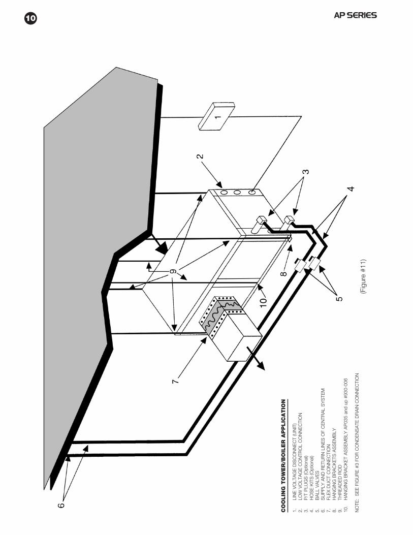
COOLING TOWER/BOILER SYSTEMS:
(Figure #11)
The cooling tower and boiler water loop temperature isusually maintained between 50˚ F to 100 ˚ F to assureadequate cooling and heating performance.
In the cooling mode, heat is rejected from the FHP unitinto the water loop. A cooling tower providesevaporative cooling to the loop water thus maintaininga constant supply temperature to the unit. Whenutilizing open cooling towers, chemical water treatmentis mandatory to ensure the water is free from corrosiveelements. A secondary heat exchanger (plate frame)between the unit and the open cooling tower may alsobe used. It is imperative that all air be eliminated fromthe closed loop side of the heat exchanger to insureagainst fouling.
In the heating mode, heat is absorbed from the waterloop. A boiler can be utilized to maintain the loop at thedesired temperature.
CAUTION: Water piping exposed to extreme lowambient temperatures is subject to freezing.
Consult the specification sheets for piping sizes. Teflontape sealer should be used when connecting to the unitto insure against leaks and possible heat exchangerfouling. Do not overtighten the connections. Flexible
8 AP SERIES
hoses should be used between the unit and the rigidsystem to avoid possible vibration. Ball valves shouldbe installed in the supply and return lines for unitisolation and unit water flow balancing.Pressure/temperature ports are recommended in bothsupply and return lines for system flow balancing.Water flow can be accurately set by measuring thewater-to-refrigerant heat exchangers water sidepressure drop. See specification sheets for water flowvs. pressure drop information.
No unit should be connected to the supply or returnpiping until the water system has been completelycleaned and flushed to remove any dirt, piping chips orother foreign material. Supply and return hoses shouldbe connected together during this process to ensurethe entire system is properly flushed. After the cleaningand flushing has taken place the unit may beconnected to the water loop and should have all valveswide open.
EARTH COUPLED SYSTEMS:
(Figure #12)
Closed loop and pond applications require specializeddesign knowledge.No attempt at these installationsshould be made unless the dealer has receivedspecialized training. Utilizing FHP’s Ground LoopPumping Package (GLP), makes the installation easy.Anti-freeze solutions are utilized when low evaporatingconditions are expected to occur. Refer to the GLPinstallation manuals for more specific instructions.
SYSTEM CHECKOUT:
• After completing the installation, and before energizingthe unit, the following system checks should be made:
• Verify that the supply voltage to the heat pump is inaccordance with the nameplate ratings.
• Make sure that all electrical connections are tight andsecure.
• Check the electrical fusing and wiring for the correctsize.
• Verify that the low voltage wiring between thethermostat and the unit is correct.
• Verify that the water piping is complete and correct.• Check that the water flow is correct, and adjust if
necessary.• Check the blower for free rotation, and that it is secured
to the shaft.• Verify that vibration isolation has been provided.• Unit is serviceable. Be certain that all access panels are
secured in place.
UNIT START-UP:
1. Set the thermostat to the highest setting.
2. Set the thermostat system switch to "COOL", and thefan switch to the "AUTO" position. The reversing valvesolenoid should energize. The compressor and fanshould not run.
3. Reduce the thermostat setting approximately 5 degreesbelow the room temperature.
4. Verify the heat pump is operating in the cooling mode.
5. Turn the thermostat system switch to the "OFF"position. The unit should stop running and the reversingvalve should deenergize.
6. Leave the unit off for approximately (5) minutes to allowfor system equalization.
7. Turn the thermostat to the lowest setting.
8. Set the thermostat switch to "HEAT".
9. Increase the thermostat setting approximately 5degrees above the room temperature.
10. Verify the heat pump is operating in the heating mode.
11. Set the thermostat to maintain the desired spacetemperature.
12. Check for vibrations, leaks, etc...
MAINTENANCE:
1. Filter changes or cleanings are required at regularintervals. The time period between filter changes willdepend upon type of environment the equipment isused in. In a single family home, that is not underconstruction, changing or cleaning the filter every 60days is sufficient. In other applications such as motels,where daily vacuuming produces a large amount of lint,filter changes may be need to be as frequent asbiweekly.
WARNING: Equipment should never be used duringconstruction due to likelihood of wall board dustaccumulation in the air coil of the equipment whichpermanently affects the performance and mayshorten the life of the equipment.
2. An annual “checkup” is recommended by a licensedrefrigeration mechanic. Recording the performancemeasurements of volts, amps, and water temperaturedifferences (both heating and cooling) is recommended.This data should be compared to the information on theunit’s data plate and the data taken at the originalstartup of the equipment.
3. Lubrication of the blower motor is not required,however may be performed on some motors to extendmotor life. Use SAE-20 non-detergent electric motor oil.
4. The condensate drain should be checked annually bycleaning and flushing to insure proper drainage.
5. Periodic lockouts almost always are caused by air orwater flow problems. The lockout (shutdown) of the unitis a normal protective measure in the design of theequipment. If continual lockouts occur call a mechanicimmediately and have them check for: water flowproblems, water temperature problems, air flowproblems or air temperature problems. Use of thepressure and temperature charts for the unit may berequired to properly determine the cause.
(Fig
ure
#10)
9AP SERIES
WE
LL W
ATE
R A
PP
LIC
ATIO
NS
(50°
F E
WT
MIN
.)
1.LI
NE
VO
LTA
GE
DIS
CO
NN
EC
T (U
NIT
)2.
FLE
X D
UC
T C
ON
NE
CTI
ON
3.LO
W V
OLT
AG
E C
ON
TRO
L C
ON
NE
CTI
ON
4.LI
NE
VO
LTA
GE
CO
NN
EC
TIO
N5.
VIB
RA
TIO
N P
AD
6.P
/T P
OR
TS7.
HO
SE
KIT
S (O
ptio
nal)
8.B
ALL
VA
LVE
S9.
SO
LEN
OID
VA
LVE
SLO
W C
LOS
ING
10.
CO
ND
EN
SA
TE D
RA
IN C
ON
NE
CTI
ON
11.
PR
ES
SU
RE
TA
NK
(Opt
iona
l)12
.LI
NE
VO
LTA
GE
DIS
CO
NN
EC
T (E
LEC
TRIC
HE
ATE
R)
NO
TE:
SE
E F
IGU
RE
#3
FOR
CO
ND
EN
SA
TE D
RA
IN C
ON
NE
CTI
ON
10 AP SERIES
CO
OLIN
G T
OW
ER
/BO
ILE
R A
PP
LIC
ATIO
N
1.LI
NE
VO
LTA
GE
DIS
CO
NN
EC
T (U
NIT
)2.
LOW
VO
LTA
GE
CO
NTR
OL
CO
NN
EC
TIO
N3.
P/T
PLU
GS
(Opt
iona
l)4.
HO
SE
KIT
S (O
ptio
nal)
5.B
ALL
VA
LVE
S6.
SU
PP
LY A
ND
RE
TUR
N L
INE
S O
F C
EN
TRA
L S
YS
TEM
7.FL
EX
DU
CT
CO
NN
EC
TIO
N8.
HA
NG
ING
BR
AC
KE
TS A
SS
EM
BLY
9.TH
RE
AD
ED
RO
D10
.H
AN
GIN
G B
RA
CK
ET
AS
SE
MB
LY A
P03
5 an
d up
#93
0-00
6
NO
TE:
SE
E F
IGU
RE
#3
FOR
CO
ND
EN
SA
TE D
RA
IN C
ON
NE
CTI
ON
(Fig
ure
#11)
AP SERIES 11
EARTH COUPLED APPLICATION
1. LINE VOLTAGE DISCONNECT (UNIT)2. FLEX DUCT CONNECTION3. LOW VOLTAGE CONTROL CONNECTION4. LINE VOLTAGE CONNECTION (UNIT)5. P/T PORTS6. VIBRATION PAD7. CONDENSATE DRAIN8. GROUND LOOP CONNECTION KIT (555-000,001)9. GROUND LOOP PUMPING PACKAGE (GL001-1 or 002-1)10. POLYETHELENE WITH INSULATION11. LINE VOLTAGE DISCONNECT (ELECTRIC HEATER)
NOTE: SEE FIGURE #3 FOR CONDENSATE DRAIN CONNECTION
(Figure #12)
AP SERIES12
(Figure #13)
13AP SERIES
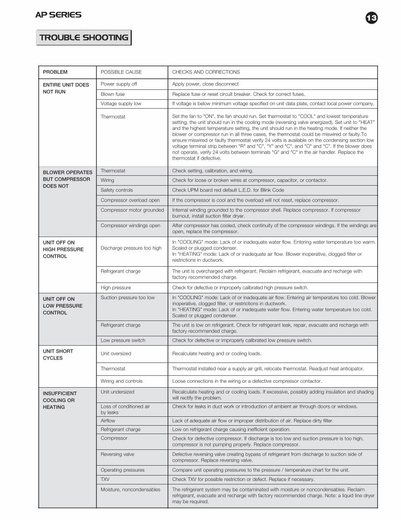
TROUBLE SHOOTING
PROBLEM POSSIBLE CAUSE CHECKS AND CORRECTIONS
ENTIRE UNIT DOESNOT RUN
Power supply off Apply power, close disconnect
Blown fuse Replace fuse or reset circuit breaker. Check for correct fuses.
Voltage supply low If voltage is below minimum voltage specified on unit data plate, contact local power company.
Thermostat Set the fan to "ON", the fan should run. Set thermostat to "COOL" and lowest temperaturesetting, the unit should run in the cooling mode (reversing valve energized). Set unit to "HEAT"and the highest temperature setting, the unit should run in the heating mode. If neither theblower or compressor run in all three cases, the thermostat could be miswired or faulty.Toensure miswired or faulty thermostat verify 24 volts is available on the condensing section lowvoltage terminal strip between "R" and "C", "Y" and "C", and "O" and "C". If the blower doesnot operate, verify 24 volts between terminals "G" and "C" in the air handler. Replace thethermostat if defective.
BLOWER OPERATESBUT COMPRESSORDOES NOT
Thermostat Check setting, calibration, and wiring.
Wiring Check for loose or broken wires at compressor, capacitor, or contactor.
Safety controls Check UPM board red default L.E.D. for Blink Code
Compressor overload open If the compressor is cool and the overload will not reset, replace compressor.
Compressor motor grounded Internal winding grounded to the compressor shell. Replace compressor. If compressorburnout, install suction filter dryer.
Compressor windings open After compressor has cooled, check continuity of the compressor windings. If the windings areopen, replace the compressor.
UNIT OFF ONHIGH PRESSURECONTROL
Discharge pressure too highIn "COOLING" mode: Lack of or inadequate water flow. Entering water temperature too warm.Scaled or plugged condenser.In "HEATING" mode: Lack of or inadequate air flow. Blower inoperative, clogged filter orrestrictions in ductwork.
Refrigerant charge The unit is overcharged with refrigerant. Reclaim refrigerant, evacuate and recharge withfactory recommended charge.
High pressure Check for defective or improperly calibrated high pressure switch.
UNIT OFF ONLOW PRESSURECONTROL
Suction pressure too low In "COOLING" mode: Lack of or inadequate air flow. Entering air temperature too cold. Blowerinoperative, clogged filter, or restrictions in ductwork.In "HEATING" mode: Lack of or inadequate water flow. Entering water temperature too cold.Scaled or plugged condenser.
Refrigerant charge The unit is low on refrigerant. Check for refrigerant leak, repair, evacuate and recharge withfactory recommended charge.
Low pressure switch Check for defective or improperly calibrated low pressure switch.
UNIT SHORTCYCLES
Unit oversized Recalculate heating and or cooling loads.
Thermostat Thermostat installed near a supply air grill, relocate thermostat. Readjust heat anticipator.
Wiring and controls Loose connections in the wiring or a defective compressor contactor.
INSUFFICIENTCOOLING ORHEATING
Unit undersized Recalculate heating and or cooling loads. If excessive, possibly adding insulation and shadingwill rectify the problem.
Loss of conditioned airby leaks
Check for leaks in duct work or introduction of ambient air through doors or windows.
Airflow Lack of adequate air flow or improper distribution of air. Replace dirty filter.
Refrigerant charge Low on refrigerant charge causing inefficient operation.
Compressor Check for defective compressor. If discharge is too low and suction pressure is too high,compressor is not pumping properly. Replace compressor.
Reversing valve Defective reversing valve creating bypass of refrigerant from discharge to suction side ofcompressor. Replace reversing valve.
Operating pressures Compare unit operating pressures to the pressure / temperature chart for the unit.
TXV Check TXV for possible restriction or defect. Replace if necessary.
Moisture, noncondensables The refrigerant system may be contaminated with moisture or noncondensables. Reclaimrefrigerant, evacuate and recharge with factory recommended charge. Note: a liquid line dryermay be required.
14 AP SERIES
UNIT CHECK-OUTSHEETCustomer Data
Customer Name _____________________________________________ Date _________________________________Address ____________________________________________________
_____________________________________________________Phone ______________________________________________________ Unit Number__________________________
Unit Nameplate Data
Unit Make ________________________________________Model Number ____________________________________ Serial Number________________________________Refrigerant Charge (oz) _______Compressor: RLA____________ LRA _____________Blower Motor: FLA (or NPA)__________ HP ______________Mximum Fuse Size (Amps) __________Minimum Circuit Ampacity (Amps) ____________
Unit Make ________________________________________Model Number ____________________________________ Serial Number _______________________________Max Fuse Size (Amps) _____________________________Volts / Amps_____________________ /____________________Entering Air Temperature ___________________________Leaving Air Temperature ___________________________
15AP SERIES
This chart shows approximate temperatures and pressures for a unit in good repair. The values shown are meant as a guide only and should not be used to estimatesystem charge. This chart assumes rated air flow and 80º d.b./67º w.b. entering air temperature in cooling, 70º d.b. entering air temperature in heating. Heating dataat entering fluid temperatures below 50º assumes the use of antifreeze.
As a result of continuing research and development, specifications are subject to change without notice.
OPERATING DATACOOLING HEATING
ENTERING WATER SUCTION DISCHARGE WATER AIR SUCTION DISCHARGE WATER AIRMODEL WATER FLOW PRESSURE PRESSURE TEMP TEMP PRESSURE PRESSURE TEMP TEMP
TEMP. ˚F GPM PSIG PSIG RISE ˚F DROP ˚F PSIG PSIG DROP ˚F RISE ˚F
This chart shows approximate temperatures and pressures for a unit in good repair. The values shown are meant as a guide only and should not be used to estimatesystem charge. This chart assumes rated air flow and 80º d.b./67º w.b. entering air temperature in cooling, 70º d.b. entering air temperature in heating. Heating dataat entering fluid temperatures below 50º assumes the use of antifreeze.
As a result of continuing research and development, specifications are subject to change without notice.
OPERATING DATACOOLING HEATING
ENTERING WATER SUCTION DISCHARGE WATER AIR SUCTION DISCHARGE WATER AIRMODEL WATER FLOW PRESSURE PRESSURE TEMP TEMP PRESSURE PRESSURE TEMP TEMP
TEMP. ˚F GPM PSIG PSIG RISE ˚F DROP˚ F PSIG PSIG DROP ˚F RISE ˚F
This chart shows approximate temperatures and pressures for a unit in good repair. The values shown are meant as a guide only and should not be used to estimatesystem charge. This chart assumes rated air flow and 80º d.b./67º w.b. entering air temperature in cooling, 70º d.b. entering air temperature in heating. Heating dataat entering fluid temperatures below 50º assumes the use of antifreeze.
As a result of continuing research and development, specifications are subject to change without notice.
OPERATING DATACOOLING HEATING
ENTERING WATER SUCTION DISCHARGE WATER AIR SUCTION DISCHARGE WATER AIRMODEL WATER FLOW PRESSURE PRESSURE TEMP TEMP PRESSURE PRESSURE TEMP TEMP
TEMP. ˚F GPM PSIG PSIG RISE ˚F DROP ˚F PSIG PSIG DROP ˚F RISE ˚F
While every effort has been made to ensure the accuracy of this parts list changes in our vendors may necessitate part substitutions. Please check with FHP Customer Service for the latest information.
FHP MANUFACTURING
All models in this price sheet reflect our current vintage. For discontinued models please contact the factory. To ensure you receive the correct part please have the full model and serial number available.
Prices contained herein are to be used with parts multipliers only . These price sheets should be used solely for parts prices only. Do not use this price sheet for installed cost for any of the items contained. Consult equipment price sheets or contact
FHP customer service for installed costs.
PARTS PRICE LIST
REV 2/08
Page 1
1 2 3 5 6 11E M 0 1 - -
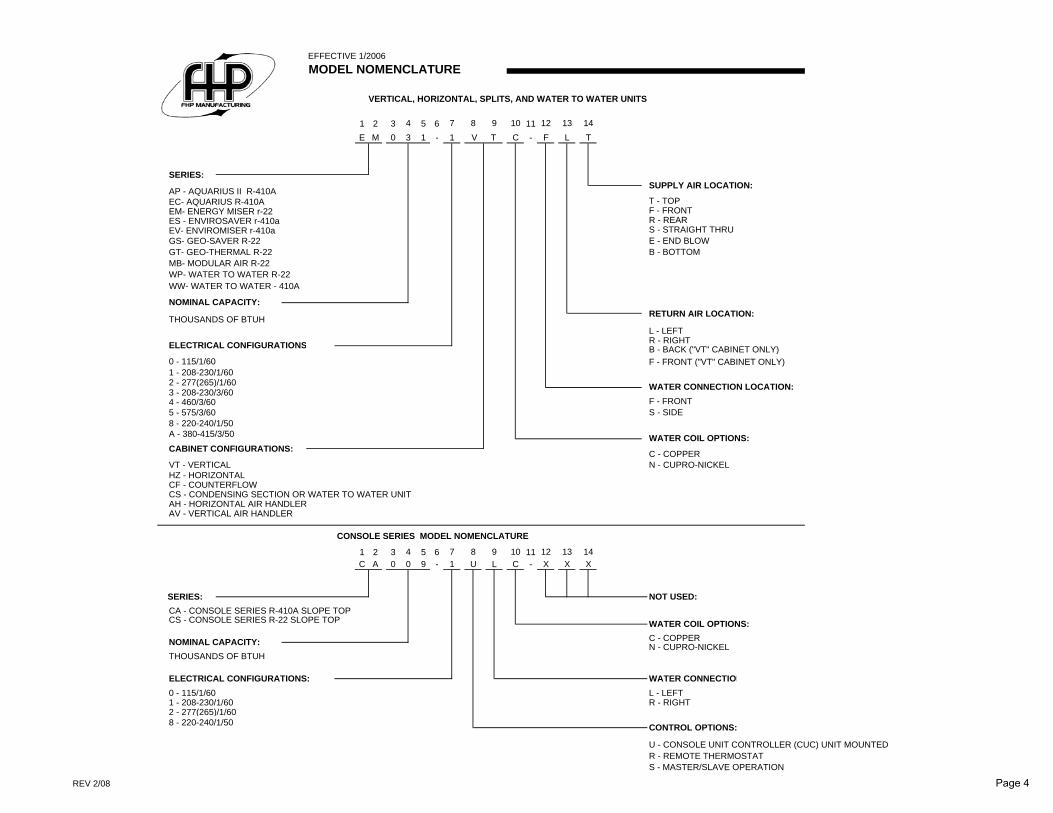
AP - AQUARIUS II R-410AEC- AQUARIUS R-410A T - TOPEM- ENERGY MISER r-22 F - FRONTES - ENVIROSAVER r-410a R - REAREV- ENVIROMISER r-410a S - STRAIGHT THRUGS- GEO-SAVER R-22 E - END BLOWGT- GEO-THERMAL R-22 B - BOTTOMMB- MODULAR AIR R-22WP- WATER TO WATER R-22WW- WATER TO WATER - 410A
THOUSANDS OF BTUHL - LEFTR - RIGHTB - BACK ("VT" CABINET ONLY)
0 - 115/1/60 F - FRONT ("VT" CABINET ONLY)1 - 208-230/1/602 - 277(265)/1/603 - 208-230/3/604 - 460/3/60 F - FRONT5 - 575/3/60 S - SIDE8 - 220-240/1/50A - 380-415/3/50
C - COPPERVT - VERTICAL N - CUPRO-NICKELHZ - HORIZONTALCF - COUNTERFLOW CS - CONDENSING SECTION OR WATER TO WATER UNITAH - HORIZONTAL AIR HANDLERAV - VERTICAL AIR HANDLER
1 2 3 5 6 11C A 0 9 - -
CA - CONSOLE SERIES R-410A SLOPE TOPCS - CONSOLE SERIES R-22 SLOPE TOP
C - COPPERN - CUPRO-NICKEL
THOUSANDS OF BTUH
0 - 115/1/60 L - LEFT1 - 208-230/1/60 R - RIGHT 2 - 277(265)/1/608 - 220-240/1/50
U - CONSOLE UNIT CONTROLLER (CUC) UNIT MOUNTEDR - REMOTE THERMOSTATS - MASTER/SLAVE OPERATION
WATER CONNECTION LOCATION:
WATER COIL OPTIONS:
9 10 12
CONTROL OPTIONS:
13 14
SUPPLY AIR LOCATION:
NOT USED:
13 14X
RETURN AIR LOCATION:
WATER COIL OPTIONS:
1 C
WATER CONNECTION
X
12
SERIES:
U L
4 7
4 70 X
EFFECTIVE 1/2006
CABINET CONFIGURATIONS:
3
MODEL NOMENCLATURE
8 9
VERTICAL, HORIZONTAL, SPLITS, AND WATER TO WATER UNITS
L10
8
NOMINAL CAPACITY:
ELECTRICAL CONFIGURATIONS:
TTV
CONSOLE SERIES MODEL NOMENCLATURE
1 C F
SERIES:
NOMINAL CAPACITY:
ELECTRICAL CONFIGURATIONS
REV 2/08 Page 4
FHP WARRANTY CODE / SERIAL NUMBER IDENTIFICATION
FIRST LETTER IS THE YEAR
1994 1995 1996 1997 1998 1999 2000 2001 2002A B C D E F G H J
1971 1972 1973 1974 1975 1976 1977 1978 1979
2003 2004 2005 2006 2007 2008 2009 2010 2011K L M N P R S T U
1980 1981 1982 1983 1984 1985 1986 1987 1988
2012 2013 2014 2015 2016V W X Y Z
1989 1990 1991 1992 1993
A JANUARY G JULYB FEBRUARY H AUGUSTC MARCH J SEPTEMBERD APRIL K OCTOBERE MAY L NOVEMBERF JUNE M DECEMBER
EXAMPLE: DC0123456 where D = 1997 OR 1974 & C = MARCH
IF THERE IS DOUBT IN THE YEAR THAT A UNIT WAS BUILT PLEASE CONTACT FHP CUSTOMER SERVICE FOR VERIFICATION
While every effort has been made to ensure the accuracy of this parts list changes in our vendors may necessitate part substitutions. Please check with FHP Customer Service for latest information.