17
Guide to Regulators

G u i d e t o R e g u l a t o r s
32
I n t r o d u c t i o n
Choosing the right regulatorfor your application is critical –and often difficult. Productapplication, gas service, andrequired delivery pressure allinfluence regulator selection.At Matheson, we understandgases, and we understand theimportance of using theappropriate equipment foreach gas. Matheson’s Guideto Regulators is a valuable toolthat will help you pick theright product for yourapplication, and get the mostreliable results.
I n d e x
S e c t i o n 1
p a g e 4
R e g u l a t o r P r i m e r
S e c t i o n 2
p a g e 1 0
M a t h e s o n ’ s P r o d u c tL i n e
S e c t i o n 3
p a g e 1 6
R e g u l a t o r O p t i o n sa n d A c c e s s o r i e s
S e c t i o n 4
p a g e 2 0
U s i n g Yo u rR e g u l a t o r
S e c t i o n 5
p a g e 2 7
P e r f o r m a n c eE v a l u a t i o n a n dTr o u b l e s h o o t i n g
S e c t i o n 6
p a g e 3 0
G l o s s a r y o fR e g u l a t o r Te r m s

54
DeliveryPressure
InletPressure
Control Elementor
Main Valve
Sensing Element
LoadingMechanism
There are three basic operating components in most regulators: aloading mechanism, a sensing element, and a control element. Thesethree components work together to accomplish pressure reduction.
The Loading Mechanism determines the setting of the regulatordelivery pressure. Most regulators use a spring as the loadingmechanism. When the regulator hand knob is turned, the spring iscompressed. The force that is placed on the spring is communicatedto the sensing element and the control element to achieve the outletpressure.
The Sensing Element senses the force placed on the spring to set thedelivery pressure. Most regulators use a diaphragm as the sensingelement. The diaphragms may be constructed of elastomers or metal.The sensing element communicates this change in force to the controlelement.
The Control Element is a valve that actually accomplishes thereduction of inlet pressure to outlet pressure. When the regulatorhand knob is turned, the spring (loading mechanism) is compressed.The spring displaces the diaphragm (sensing element). The diaphragmthen pushes on the control element, causing it to move away from theregulator seat. The orifice becomes larger in order to provide the flowand pressure required.
S e c t i o n 1
R e g u l a t o r P r i m e r
H o w a R e g u l a t o r Wo r k s
What makes a high purity regulatorhigh purity?
High purity applications require equipmentthat will help maintain the purity of thesystem. High purity applications are sensitiveto contamination from elements such asmoisture, oxygen, and other gaseous vaporsthat may be present in ambient air. Thesecontaminants enter the system when theregulator is removed from the cylinder duringcylinder changeout, or they may enterthrough leaks or faulty seals.
The features of a regulator determine the typeof service for which it can be used. Aregulator intended for a high purityapplication has different features than a unitdesigned for general purpose use. Threemain features determine the suitability of aregulator for high purity applications:
Body Type: Regulator bodies may be offorged or barstock construction. A forgedbody is formed by casting metal in a moldunder pressure. A barstock body is made bymachining out a solid piece of cold-drawnmetal bar. Barstock bodies are used for highpurity applications for the following reasons:
• Reduced internal volumes: Becausebarstock bodies are machined, it is possibleto achieve a small internal cavity in theregulator body. The low internal volumemakes purging the regulator easy, allowingfor removal of contaminants like moistureand oxygen. It is difficult to achieve a lowinternal volume in the forging process;forged bodies have more “dead space” andtend to trap contaminants, and are moredifficult to purge.
F e a t u r e s D e t e r m i n e F u n c t i o n :
Barstock Construction
Forged ConstructionNote: the larger size of the forged body

76
• Tight grain structure of the metal:The cold drawing process producesmetal barstock with a very tight grainstructure. This tight grain structureprevents the regulator’s internalsurfaces from adsorbing moisture andcontaminants, allowing them to bepurged easily. The forging processproduces a more porous grainstructure; the internal surfaces of aforged body regulator tend to adsorbcontaminants, which eventually findtheir way into the system.
• Low Ra surface finish: The machiningprocess allows for very low Ra(roughness average) surface finisheson the barstock. The low Ra finishminimizes particle shedding, whichcontributes to contamination. It isdifficult to achieve a low Ra finish inthe forging process, making forgedbodies susceptible to particleshedding and contamination.
Diaphragm Material: Diaphragmsmay be constructed of elastomers(neoprene, Viton, etc.) or stainless steel.Stainless steel diaphragms are used inhigh purity regulators because they donot adsorb and release (or “offgas”)contaminants. When a regulator isremoved from a cylinder, it is exposedto ambient air. An elastomericdiaphragm will adsorb moisture andany other contaminants from the air.When the regulator is put back intoservice, the elastomeric diaphragmreleases these contaminants, whicheventually find their way back into thesystem. A stainless steel diaphragm isunable to adsorb any contaminants, soit does not contribute to systemcontamination.
F e a t u r e s I n f l u e n c e C o s t
Type of Seals: The seal betweenthe body of the regulator and thediaphragm is important inmaintaining purity. A poor sealcreates a leakage point throughwhich contaminants may enter thesystem. A metal to metal seal(metal regulator body sealing to ametal diaphragm) is the mostreliable, leak-free type of seal. Anelastomeric diaphragm can degradeover time, compromising theintegrity of this seal. Someregulator designs incorporate astainless steel diaphragm that maybe lined with an elastomer.Although the diaphragm is stainlesssteel, the seal is created between theregulator body and the elastomericliner. It is not as reliable as a metalto metal seal.
A regulator designed for high purityapplications is more costly than aregulator intended for generalpurpose use. Barstock bodies aremore costly to produce than forgedbodies due to the high amount ofmachining involved. Stainless steelis a more expensive diaphragmmaterial than elastomers. It isimportant to remember that not allregulators are created equal when itcomes to features.
RegulatorBody
Diaphragm
Seal
Seal betweenthe regulator bodyand the diaphragm
DiaphragmRegulatorBody

98
Single Stage Regulators accomplish the pressure reduction in asingle step. Delivery pressure cannot be as tightly controlled as with adual stage regulator. Single stage regulators should only be usedwhere an operator can monitor and adjust pressure as needed, orwhere the regulator is supplied a nearly constant source pressure.
Line Regulators are single stage regulators that are used to providepoint-of-use pressure monitoring and control. For example, a lab mayhave gas cylinders located in a room on the first floor. The gas may bepiped up to instruments located in a lab on the second floor. In thiscase, it is difficult to monitor the gas pressure directly at theinstruments, since the regulators are located on the cylinders on thefirst floor. A line regulator may be installed near the instruments forconvenience of monitoring the delivery pressure at the point of use.These regulators are installed directly into gas lines, and have a singledelivery pressure gauge.
HandKnob
BodyMain ValveControl Element
OUTLET INLET
Load Spring
Diaphragm
S i n g l e S t a g e R e g u l a t o rD u a l S t a g e R e g u l a t o r
Dual Stage Regulators reduce the source pressure down to thedesired delivery pressure in two steps. Each stage consists of a spring,diaphragm, and control valve. The first stage reduces the inletpressure to about three times the maximum working pressure. Thefinal pressure reduction occurs in the second stage.
The advantage of a dual stage regulator is its ability to deliver aconstant pressure, even with a decrease in inlet pressure. Forexample, as a cylinder of gas is depleted, the cylinder pressure drops.Under these conditions, single stage regulators exhibit ‘decaying inletcharacteristic’; the delivery pressure increases as a result of a decreasein inlet pressure. In a dual stage regulator, the second stagecompensates for this increase, providing a constant delivery pressureregardless of inlet pressure. The dual stage regulator is recommendedfor applications such as gas supply to analytical instruments, whereconstant delivery pressure is critical.
HandKnob
OUTLETINLET
2nd StageLoad Spring
1st StageLoad Spring
1st StageControl Valve
1st StageDiaphragm
2nd StageDiaphragm
Inner StagePressure
2nd StageControl Valve

1110
S p e c i a l t y R e g u l a t o rP r o d u c t s
The specialty regulators are intendedfor use with applications that requireparticular capabilities, such as lowdelivery pressures or high flow rates.There are general purpose and highpurity options within the specialtyregulator family.
• High Pressure Regulators:Delivery pressures up to 6,000 psig
• Corrosive Service Regulators:Used with acid forming halogens(HCl, HBr, etc.)
• High Flow Regulators: Flowrates up to 730 SCFH
• Low Pressure Regulators: Lowpositive pressure and absolutepressure
• Back Pressure Regulators:Prevent system overpressure
• Low Dead Volume Regulators:Low internal volume designed forhigh sensitivity applications
• Lecture Bottle Regulators:Corrosive and non-corrosive serviceunits for use with small lecturebottles
• Specialty Line Regulators: Lineregulators for high flow and lowdelivery pressure applications
Matheson’s regulator products are grouped into two families: BasicRegulator Products, and Specialty Regulator Products.
B a s i c R e g u l a t o rP r o d u c t s
General Purpose Regulators• Used with gases that are less than
99.995% pure• Used for applications where cost
(not purity) is the main concern• Economy and deluxe models
High Purity Regulators• Used with gases that are 99.995%
pure or higher purity• Used for applications where
maintaining system purity is themain concern
• Brass, aluminum, and stainlesssteel options
• Standard regulators or Miniatureregulators available
ULTRA-LINE® Ultra High PurityRegulators• Used for applications where the
highest possible purity is critical,such as semiconductormanufacturing
• Designed to minimize the risk ofcontamination
Basic Line Regulators• Line regulators for general
purpose, high purity, and ultrahigh purity applications
S e c t i o n 2
M a t h e s o n ’ s R e g u l a t o r P r o d u c t L i n e
Model 3180General Purpose Regulator
Model 3810High Purity Stainless Steel Regulator
Model 9460ULTRA-LINE® Regulator
Model 3230High Purity Line Regulator
Model 3210Deluxe Corrosive Regulator
Model 3396Absolute Pressure Regulator
Model 3590Low Dead Volume Regulator
Model 6342ABack Pressure Regulator

1312
P r o d u c t L i n e a t a G l a n c e
B a s i c R e g u l a t o r s
Regulator Model Design Family Series Stages FeaturesEconomy 3180 1 • Low cost forged bodiesGeneral Purpose 3280 2 • Economical neoprene diaphragms
Deluxe 1 1 • Low cost forged bodies & neoprene diaphragmsGeneral Purpose 8 2 • Rugged construction
8-F 2 • Large diaphragms provide good pressure control(with rotameter)
High Purity Brass 3530 1 High Purity Features:3120 2 • Ni plated brass barstock bodies
• 316 stainless steel diaphragms• Metal to metal seals
High Purity 3140 1 High Purity Features:Aluminum • Anodized aluminum barstock bodies
• 316 stainless steel diaphragms• Metal to metal seals
High Purity 3510 1 High Purity Features:Stainless Steel 3610 1 • 316 stainless steel bodies
3810 2 • 316 stainless steel diaphragms• Metal to metal seals• Tied seat (3610) for safety
High Purity 3550 Brass 1 High Purity Features: Miniature 3560 Al 1 • Brass, aluminum, or 316 stainless steel
3570 SS 1 barstock bodies3850 Brass 2 • 316 stainless steel diaphragms
3860 Al 2 • Metal to metal seals3870 SS 2 • Compact size
ULTRA-LINE® 9300 1 Ultra High Purity Features:Ultra High 9360 1 • 316L Stainless steel or Hastelloy® C-22 bodiesPurity 9370 1 • Autogeneous butt-welded connections
9460 2 • 10-15 rms surface finish9470 2 • Assembled in Class 100 clean room
Basic Line 3470 1 • Cast zinc (3470), brass barstock (3420), General Purpose 316 stainless steel (3230), or 316L stainless steel
3420 1 (9330) bodiesHigh Purity Brass • Neoprene (3470) or stainless steel diaphragms
3230 1 • Tied seat (9330) for safetyHigh Purity SS
9330 1Ultra Line
Applications• Air supply to valves and actuators• Inert gas supply for purging
• Calibration of pressure gauges, rotameters, and mass flow controllers• Applications with high duty cycle/demanding operating conditions
• Supply of carrier gas/detector support gas for a variety of gas chromatography applications (see Regulator Selection Guide forGC Detectors on page 16)
• Supply of calibration standards to on-line process analyzers,emission monitoring systems, etc.
• Use with ammonia, sulfur containing compounds, amines, vinylcompounds, nitric oxide
• Supply of carrier gas/detector support gas for a variety of gaschromatography applications (see Regulator Selection Guide for GCDetectors on page 16)
• Supply of calibration standards to on-line process analyzers, emission monitoring systems, etc.
• Applications requiring high purity gases and a compact regulator due tospace limitations
• All semiconductor industry gas applications
• 3470: Point-of-use regulation of inert gases• 3420 & 3230: Point-of-use regulation of high purity gases used in
chromatography or other analytical applications (see Regulator SelectionGuide for GC Detectors on page 16)
• 9330: Semiconductor applications

1514
S p e c i a l t y R e g u l a t o r s
P r o d u c t L i n e a t a G l a n c e
Regulator Model Design Family Series Stages Features
High 3020 Brass 1 • Brass or stainless steel barstock bodiesPressure 3030 Brass 1 • 316 stainless steel diaphragm (3020) or piston
3040 Brass 13060 Brass 1
3060 SS 1
Standard B15 1 • Economical nickel plated forged brassCorrosive Service
Deluxe Corrosive 3210 1 • Monel construction for superior corrosionService resistance
High Flow 3200 1 • Brass or stainless steel barstock bodies• 1/2” NPTF inlet and outlet ports
Low Pressure 8-2 2 • Economical forged brass (8-2) or high purity General Purpose brass barstock (3396) construction
(0.06-2 psig) • Economical Viton® (8-2) or 316 stainless steel3396 1 (3396) diaphragms
Absolute Pressure(-28”Hg VAC-15 psig)
Back Pressure 6342A 1 • 316L stainless steel bodies6344A 1 • 316 stainless steel diaphragm (6342A) or
316 stainless steel piston (6344A)• 6344A capable of delivering up to 700 psig
Low Dead 3590 1 • 7 cc internal volume minimizes contamination and Volume 3590TO 1 adsorption
• 316 stainless steel body and diaphragm
Lecture Bottle 3320 1 • Forged brass (3320) or PVC (3330) bodiesNon-Corrosive • Neoprene (3320) or Teflon® (3330) diaphragms
3330 1 • 3320 equipped with CGA 170 for use with non-Corrosive Service corrosives; 3330 equipped with CGA 180
for corrosive gases
Specialty Line 3540 1 • High purity stainless steel body and (2-100 psig) diaphragm
3491 1 • Low cost brass body and butyl rubber(1 mm Hg VAC-1.8 psig) diaphragm
3494 1 • High purity stainless steel body and (-28” Hg VAC-15 psig) diaphragm
3700 1 • Cast zinc body and natural rubber(2” WC-10 psig) diaphragm; “pancake” design
Applications
• Applications requiring up to 6000 psig delivery pressure• Manufacturing processes, charging of systems, purging
• Use with acid forming halogen compounds (HBr, HCl, HF)
• Applications requiring extended regulator life span in severe conditions
• Applications requiring a high flow rate such as purging of large reactor orstorage vessels
• 8-2: applications requiring a reduction of full cylinder pressure down to alow working pressure, such as fuel supply to burners or purging lowpressure environmental chambers
• 3396: applications requiring subatmospheric pressure control
• Used to relieve system overpressure, like a relief valve
• Use with mixtures containing trace quantities of reactive and/or adsorptivegases or vapors
• 3590TO specially cleaned for use with TO-14 calibration standards
• Use with lecture bottles.• 3330 designed for use with low pressure applications (1-6 psig); if higher
pressures are required, use 3570 Series Mini Regulators
• High purity, high flow applications (up to 730 SCFH)
• Non-corrosive, absolute pressure applications
• Corrosive/high purity absolute pressure applications
• Non-corrosive, low inlet pressure/low; delivery pressure applications

1716
Detector Type Detection Level Regulator
Flame Ionization Detector (FID) All Levels
Thermal Conductivity Detector (TCD) All Levels
Nitrogen Phosphorus Detector (NPD) All Levels
Flame Photometric Detector (FPD) All Levels
Photoionization Detector (PID) All Levels
Helium Ionization Detector (HID) All Levels
Electrolytic Conductivity Detector Levels >50 ppm(ELCD or Hall Detector)
Electron Capture Detector (ECD) Levels > 50 ppm
Electrolytic Conductivity Detector Levels < 50 ppm(ELCD or Hall Detector)
Electron Capture Detector (ECD) Levels < 50 ppm
Mass Selective Detector or Mass Spec All Levels(MSD or MS)
Atomic Emission Detector (AED) All Levels
Regu l a t o r Se l e c t i o n Gu i d e f o r GC De t e c t o r s
Model 3530/3120
High Purity
Brass Regulators,
Model 3420
High Purity Brass Line
Regulators
Model 3510/3810
High Purity Stainless Steel
Regulators,
Model 3230 High Purity
Stainless Steel Line Regulators
H e l i u m L e a k Te s t i n g
A helium leak test is used to determine the leak rate acrossthe diaphragm or fittings on the regulator. The leak ratevalue should be as low as possible to prevent contaminationby ambient air or escape of hazardous gases.
A complete helium leak test involves monitoring the inboardleakage and the outboard leakage of a regulator. This testingis available for a fee. Inboard leak testing involves drawingan internal vacuum on the regulator, and surrounding itwith helium. The helium leak rate from the outside of theregulator to the inside of the regulator is then monitored.Outboard leak testing is performed by pressurizing theregulator with helium and analyzing the surrounding spacefor the presence of helium. Upon completion of the tests, acertificate is written and forwarded with the item to thecustomer.
S e c t i o n 3
O p t i o n s a n d A c c e s s o r i e s
F l a s h A r r e s t o r s
Flash arrestors are safety devices that shutoff the gas flow if a flashback occurs in asystem. A flashback is the combustion of aflammable mixture within the tubing orpiping of a gas transfer system. If theflashback travels back through the pipingand reaches the regulator, the regulatorbecomes a small bomb. If it reaches thegas cylinder, the cylinder becomes a largebomb.
As the flashback occurs, it is preceded by ashock wave. The flash arrestor senses theshock wave and closes a valve that shutsoff the gas flow. The flame is detouredthrough three feet of spiral tubing in theflash arrestor, where it is extinguished.The flash arrestor also incorporates areverse flow blocking mechanism thateffectively prevents accidental mixing ofgases in the regulator. Flash arrestors areavailable in brass (Model 6103) andstainless steel (Model 6104), and may bereset and reused up to three times after aflashback has occurred.
P u r g e A s s e m b l i e s
A purge assembly is recommended for usewith toxic, corrosive, or flammable gases.The assemblies are available in a crosspurge configuration (Models 4774 and4775) and a tee purge configuration(Models 4753-4756). The tee purge andthe cross purge help to ensure safety whenworking with hazardous gases. The crosspurge also protects the system fromatmospheric contamination. The teepurge is used for general purpose corrosiveapplications; the cross purge is used forhigh purity applications where preventingcontamination is critical.
Model 4774Cross Purge Assembly
Model 6104Flash Arrestor

1918
Safety: When a regulator is removedfrom a cylinder of toxic or flammable gas,some gas is released into the workatmosphere. Some materials (such assilane) will spontaneously ignite whenexposed to air. A purge assembly is usedwith an inert gas to flush all hazardousgases from the regulator, eliminating theirrelease when the regulator is removedfrom the cylinder. Corrosive gases likehydrogen chloride present severe corrosionproblems when they are exposed tomoisture. The cross purge’s valvingconfiguration allows the regulator to beclosed off completely from the atmospherebefore removing it from the cylinder.Closing the valves prevents atmosphericmoisture from contacting the gas,minimizing corrosion.
Purity: Atmospheric contaminants likemoisture and oxygen cannot be tolerated ina high purity system. When a regulator isremoved from a cylinder, atmosphericoxygen and moisture enter the regulator.When the regulator is put back intoservice, these contaminants enter thesystem. As mentioned above, the crosspurge’s valving configuration allows theregulator to be completely isolated fromthe atmosphere, preventing contaminantsfrom entering the system.
S i n g l e S t a t i o n M a n i f o l d s
A single station manifold is used to mounta regulator to a wall. These units consistof a stainless steel bracket and a stainlesssteel flex hose with a CGA connection andintegral check valve. Wall mounting theregulator eliminates the need to handle theregulator during cylinder changeout,
minimizing the risk of it beingimproperly reinstalled. The check valvein the CGA connection prevents therelease of gas when the cylinder ischanged, and prevents ambient air fromentering the system. The Model 5330 hasbrass end connections, and the Model5430 has stainless steel end connections.
E x c e s s F l o w Va l v e s
The excess flow valve (Model 6290 Series)is designed to shut down the gas supplyin case of abnormal flow conditionscaused by rupture, fire, ormalfunctioning valves. The valve willautomatically detect excess flow when theevent occurs and will shut down thesupply flow immediately so that theremaining contents of the cylinder(s)does not empty into the work or storagearea. This feature is critical with toxic,poisonous, or flammable gases, but canalso be important when dealing withinert gases in small, poorly ventilatedareas where asphyxiation is a potentialhazard.
Model 6290Excess Flow Valve

2120
S e c t i o n 4 – U s i n g Yo u r R e g u l a t o r
I n s t a l l i n g t h e R e g u l a t o r
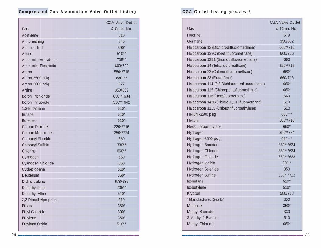
Regulators are equipped with CGA (Compressed Gas Association)fittings for connection to cylinders. Each CGA connection has anumerical designation, and a listing of gases with which it may beused. The CGA prevents a regulator from being used on incompatiblegases. For example, the CGA connection designated for use withoxygen (CGA 540) cannot be used on a cylinder of hydrogen. The tableon page 24 lists common gases and their corresponding CGAconnections.
C o n n e c t i n g t h e R e g u l a t o r t o t h e C y l i n d e ra n d S e t t i n g t h e D e l i v e r y P r e s s u r e
1. Close the regulator by rotating the hand knob in acounterclockwise direction.
2. Close the regulator outlet valve by rotating the valveknob in a clockwise direction.
3. Connect the regulator to the cylinder. The regulatorshould be attached to the cylinder without forcing thethreads. If the inlet of the regulator does not fit thecylinder outlet, it is likely that the regulator is notintended for the gas service.
CylinderValveRegulator Outlet
Valve
Regulator HandKnob
4. Slowly open the gas cylinder valve. Check the inletpressure gauge to ensure that it registers the expectedvalue. Low cylinder pressure may indicate a leakingvalve, which can be a serious safety issue.
5. Check all high-pressure connections for leaks using anapproved soap solution or leak detection device.
6. Open the cylinder valve completely.
7. Adjust the regulator hand knob to raise the deliverypressure to the desired value. Do not exceed themaximum delivery pressure indicated by the modelnumber label on the regulator.
8. Open the outlet valve on the regulator to establish gasflow to the system. This valve is used to control thegas flow. The regulator itself should not be used as aflow controller by adjusting the pressure to obtaindifferent flow rates. This practice defeats the purposeof the pressure regulator, and may result in a pressuresetting that is in excess of the design pressure of thesystem.
9. After flow is established, the set delivery pressure maydecrease slightly. Check to see that the deliverypressure is as desired and make any necessaryadjustments.
R e m o v i n g t h e R e g u l a t o r f r o m t h e C y l i n d e r
For temporary shutdown (less than 30-minute duration), simply closethe regulator outlet valve.
For extended shutdown (beyond 30-minute duration) follow thesesteps:
1. Shut off the gas cylinder valve completely.
2. Shut down any additional gas supplies that may besupplying gas to the system.
3. Open the regulator and the outlet valve to drain thecontents of the regulator through the system in use.Both regulator gauges should descend to zero.
4. When using a toxic or other hazardous gas, purge theregulator and system with an inert gas (seeinstructions on Purging the Regulator, on page 23).

2322
5. Close the regulator by rotating the knobcounterclockwise. Close the outlet valve by rotating itclockwise.
6. Disconnect the regulator from the system ordownstream equipment.
7. Disassemble the regulator from the cylinder by slowlyloosening the cylinder connection. Listen for gasseepage. If leakage is evident, re-tighten the cylinderconnection immediately, and check the cylinder valvefor proper closure. If leakage occurs when thecylinder valve is closed, and the regulator has beendrained of all gases, contact the gas supplierimmediately.
8. Replace the plug into the cylinder valve outlet (whereapplicable). Replace the cap on the cylinder over thevalve. Remove the cylinder from the work place andput the cylinder into a safe storage area. Replace theempty cylinder with a new one and re-install theregulator.
Pu r g i n g t h e R egu l a t o r U s i n g a C r o s sPu r g e A s s emb l y
1. Close cylinder valve 1 and valve 2.
2. Open valves 3 and 4 allowing the inert purge gas to flushthe Cross Purge Assembly.
3. Alternately close and open valve 3 a few times to dilute anygas trapped in the Cross Purge Assembly by pressurizingand venting.
4. Close valve 3. Close valve 4 until barely open. This willensure a continuous small flow of inert purge gas duringthe time the inlet connection is open to the atmosphere.
5. Disconnect the regulator from the empty cylinder andreconnect it to the replacement cylinder.
6. Close valve 4.
7. Open valve 3. Evacuate the assembly, if possible, then re-close valve 3. If this is not possible, steps 2 and 3 shouldbe repeated.
8. Open the cylinder valve 1 long enough to fill the CrossPurge Assembly with cylinder gas, and then re-close.
9. Repeat steps 7 and 8 once more if evacuation facilities areavailable; four more times if venting to atmosphere. At225 psig cylinder pressure, this practice will dilute thepurge gas to below 1 ppm.
10. Check to ensure that valves 3 and 4 are securely closed; thevalve handles should be horizontal. Valve 2 may beopened. The handle will indicate the direction of the flow.
Inert Purge Gas
4
1
3
2
CylinderValve
Outlet Valve
System
Vent
VacuumPump
Purging the Regulator
Cross PurgeAssembly
2524
CGA Valve Outlet
Gas & Conn. No.
Acetylene 510Air, Breathing 346Air, Industrial 590*Allene 510**Ammonia, Anhydrous 705**Ammonia, Electronic 660/720Argon 580*/718Argon-3500 psig 680***Argon-6000 psig 677Arsine 350/632Boron Trichloride 660**/634Boron Trifluoride 330**/6421,3-Butadiene 510*Butane 510*Butenes 510*Carbon Dioxide 320*/716Carbon Monoxide 350*/724Carbonyl Fluoride 660Carbonyl Sulfide 330**Chlorine 660**Cyanogen 660Cyanogen Chloride 660Cyclopropane 510*Deuterium 350*Dichlorosilane 678/636Dimethylamine 705**Dimethyl Ether 510*2,2-Dimethylpropane 510Ethane 350*Ethyl Chloride 300*Ethylene 350*Ethylene Oxide 510**
CGA Valve Outlet
Gas & Conn. No.
Fluorine 679Germane 350/632Halocarbon 12 (Dichlorodifluoromethane) 660*/716Halocarbon 13 (Chlorotrifluoromethane) 660/716Halocarbon 13B1 (Bromotrifluoromethane) 660Halocarbon 14 (Tetrafluoromethane) 320*/716Halocarbon 22 (Chlorodifluoromethane) 660*Halocarbon 23 (Fluoroform) 660/716Halocarbon 114 (2,2-Dichlorotetrafluoroethane) 660*Halocarbon 115 (Chloropentafluoroethane) 660*Halocarbon 116 (Hexafluoroethane) 660Halocarbon 142B (Chloro-1,1-Difluoroethane) 510Halocarbon 1113 (Chlorotrifluoroethylene) 510Helium-3500 psig 680***Helium 580*/718Hexafluoropropylene 660*Hydrogen 350*/724Hydrogen-3500 psig 695***Hydrogen Bromide 330**/634Hydrogen Chloride 330**/634Hydrogen Fluoride 660**/638Hydrogen Iodide 330**Hydrogen Selenide 350Hydrogen Sulfide 330**/722Isobutane 510*Isobutylene 510*Krypton 580/718“Manufactured Gas B” 350Methane 350*Methyl Bromide 3303 Methyl-1-Butene 510Methyl Chloride 660*
Compressed Gas Association Valve Outlet Listing CGA Outlet Listing (continued)

2726
S e c t i o n 5 –
P e r f o r m a n c e E v a l u a t i o n
a n d T r o u b l e S h o o t i n g
Several things are evaluated to determine a regulator’sperformance.
• Pressure regulation as a function of flow: All regulatorsexperience some delivery pressure drop with increased flow rate.The smaller the drop as flow is increased, the better theperformance.
• Pressure regulation as a function of inlet pressure. As acylinder’s contents are depleted and the inlet pressure drops, theregulator delivery pressure may either rise or fall depending on theregulator design. In both cases, this is known as regulator“droop.” Two stage regulators generally provide better regulationunder these circumstances.
• “Lockup” of a regulator. Lockup is the difference in pressurebetween a flowing and a non-flowing condition. If a regulator hasits delivery pressure set while gas is flowing, and flow is suddenlystopped, a small rise in delivery pressure (lockup) will occur beforethe regulator’s valve closes fully. The lower the lockup, the betterthe performance.
• Seat leakage of the regulator. Seat leakage is the tendency ofgas to leak across the regulator seat, when the regulator outletvalve knob is fully closed (turned counterclockwise) and a highpressure source exists on the inlet side. A low leakage value ispreferred.
• Leakage rate across the diaphragm or fittings on theregulator. This leakage value is normally measured using heliumgas and a mass spectrometer or other type of helium leak detector.Regulators for specialty gas service may have published values oftypical leakage rates either inboard (from the atmosphere into theregulator) or outboard (from the inside of the regulator to theatmosphere). For safety, it is important that this leak rate value beas low as possible in order to prevent possible contamination byambient air and moisture or escape of hazardous gases.
CGA Valve Outlet
Gas & Conn. No.
Methyl Fluoride 350Methyl Mercaptan 330**Monomethylamine 705**Neon 580*/718Nitric Oxide 660/712Nitrogen 580*/718Nitrogen-3500 psig 680***Nitrogen-6000 psig 677Nitrogen Dioxide 660Nitrogen Trioxide 660Nitrous Oxide 326*Octofluorocyclobutane 660*Oxygen 540*/714Oxygen Mixtures Over 23% 296Perfluoropropane 660*/716Phosgene 660Phosphine 350/632Phosphorus Pentafluoride 660**Propane 510*Propylene 510*Silane (High Pressure) 350/632Silicone Tetrafluoride 330**/642Sulfur Dioxide 660**Sulfur Hexafluoride 590*/716Sulfur Tetrafluoride 330**Trimethylamine 705**Vinyl Bromide 510Vinyl Methyl Ether 510Xenon 580**/718
*Lecture bottles use CGA No. 170**Lecture bottles use CGA No. 180***For information on CGA 680 and 695 connections contact your nearest Matheson office.
CGA Outlet Listing (continued)

2928
Problem Cause Action
Gauges do not read zero Faulty gauges Replace gaugeswhen gas is drained fromthe regulator
Gas coming out of the outlet Seat failure or imminent Replace seat;when the regulator is in the seat failure recondition regulatorclosed position.
Delivery pressure rising Seat failure or imminent Replace seat;with the following conditions: seat failure recondition regulatora) cylinder valve open, b) regulator set at a given
delivery pressure, and c) outlet valve closed
for five to ten minutes
Gas leakage from hand Deficient diaphragm or Replace diaphragm knob area diaphragm seal or seal; recondition
regulator
R e a d i n g F l o w C u r v e s
The flow properties of a regulator are illustratedby the flow curve. The vertical axis indicatesthe delivery pressure at which the regulator isset, and the horizontal axis indicates the gasflow that the regulator passes. The curves aremade by setting the delivery pressure whilethere is no gas flow, and then slowly openingthe outlet valve downstream while measuringboth the flow and the delivery pressure.Typically, as flow increases, delivery pressuredrops. The portion of the curve to the far left isflat; in this range, the regulator demonstrates astable pressure regulation although the flow ischanging. For example, increasing the flowfrom point “A” to point “B” results in a slightdecrease in pressure. The portion of the curveto the right shows a rapid drop in pressure withincreasing flow rate, indicating that theregulator valve seat is almost wide open. If flowis increased from point “B” to point “C”, there isa large drop in pressure that is typical for allregulators.
0
20
40
60
80
100
R e g u l a t o r Tr o u b l e s h o o t i n g
There are a number of indications of regulator malfunction. Thisguide lists some of the potential problems that may be experienced.
If any of the above problems are experienced, please return theregulator to Matheson for repair.

3130
Inlet Pressure (P1) – The pressure of the gas at the supplyconnection of a regulator or valve. Typicalunits of measure are psig, bar, or pascal.
Leakage, Inboard – Leakage through an external joint or sealwhere the direction of flow is from theoutside into the regulator or valve. Theleakage rate is measured in atm cc/secHe(lium).
Leakage, Outboard – Leakage through an external joint or sealwhere the direction of flow is from theinside of the regulator or valve to theoutside. The leakage rate is measured inatm cc/sec He(lium), and the pressureinside the regulator should be stated.
Load Element – One of the three basic elements of apressure reducing regulator (usually aspring). It provides the means by which theoperator can set the force that determinesthe outlet pressure of the regulator.
Lock-up – The outlet pressure increase that occursabove the “set pressure” as the flow isdecreased to zero.
Outlet Pressure (P2) – The pressure of the gas from the dischargeconnection of a regulator or valve.
Sensing Element – One of the three basic elements of apressure-reducing regulator, typically adiaphragm. It senses the changes in theoutlet pressure, permitting the regulator toreact in an attempt to return to the original“set pressure” by increasing or decreasingpressure.
Set Pressure – The desired operational outlet pressure for aregulator, normally stated at NO FLOWconditions.
ULTRA-LINE is a registered trademark of Matheson Gas ProductsTeflon and Viton are registered trademarks of E.I. DupontHastelloy is a registered trademark of Union Carbide
S e c t i o n 6 :
G l o s s a r y o f R e g u l a t o r T e r m s
The following terms may be encountered when dealing with regulators.
Burst Pressure – A design test pressure which determines theultimate structural strength of a regulatoror valve. Permanent deformation andleakage are permitted, but parts mustremain assembled (no sudden ruptures).
Captured Venting – A feature incorporated in a self-ventingpressure reducing regulator which providesan additional port to permit the piping awayof the expelled gas from the regulator’s ventvalve.
Control Element – One of the three basic elements of apressure regulator. It acts to reduce a highinlet pressure to a lower working or deliverypressure. The control element is sometimescalled a main valve, valve stem, or poppet.
Cv – See “Flow Capacity”Decaying Inlet Characteristic – The effect of the set pressure of a regulator
as a result of an inlet pressure change;normally an increase in outlet pressure dueto a decrease in inlet pressure.
Diaphragm – A type of sensing element used in aregulator. Common diaphragm materialsare Buna-N, Viton, Ethylene Propylene, 316Stainless Steel, and Elgiloy.
Droop – The outlet pressure change (or offset) fromthe “set pressure” which occurs as flow rateincreases.
Flow Capacity (Cv) – The maximum flow capability of a regulatoror valve established at a specific set ofconditions. The standard coefficient is theterm ‘Cv’, which is defined as the flow ofone GPM of water at one PSI pressure drop.The term Cv for gaseous service isdependent on the ratio of inlet to outletpressure and must be determined by the useof the appropriate formulae.

BR-71/1-99 Printed in USA
United StatesARIZONA (Phoenix)TEL: 602-894-1387FAX: 909-987-3494
CALIFORNIA(Northern)6775 Central AvenueNewark 94560TEL: 510-793-2559FAX: 510-790-6241
CALIFORNIA (Southern)8800 Utica AvenueCucamonga 91730TEL: 909-987-4611FAX: 909-987-3494
COLORADO (Denver)TEL: 303-973-7714FAX: 909-987-3494
GEORGIA (Atlanta)6874 S. Main StreetP.O. Box 136Morrow 30260TEL: 770-961-7891FAX: 770-968-1268
ILLINOIS (Chicago)TEL: 773-242-1321FAX: 815-727-1676
ILLINOIS (Joliet)Manhattan Road& Richards StreetP.O. Box 96Joliet 60434TEL: 815-727-4848FAX: 815-727-1676
LOUISIANA (Baton Rouge Area)1931 South Southland AvenueGonzales 70737TEL: 225-647-5303FAX: 281-471-9518
MASSACHUSETTS(Gloucester)61 Grove StreetP.O. Box 1147Gloucester 01930TEL: 978-283-7700FAX: 978-283-6177
MISSOURI (St. Louis)TEL: 314-645-5105FAX: 815-727-1676
NEW JERSEY(Northern)932 Paterson Plank RoadP.O. Box 85East Rutherford, NJ 07073TEL: 201-933-2400FAX: 201-933-1928
NEW JERSEY(Southern)603 Heron DriveP.O. Box 38Bridgeport 08014TEL: 609-467-2770FAX: 609-467-3415
NEW YORK (Buffalo)TEL: 716-832-9286FAX: 330-425-1791
OHIO (Cleveland)1650 Enterprise Pkwy.Twinsburg 44087TEL: 330-425-4406FAX: 330-425-1791
OHIO (Miamisburg)TEL: 937-236-3021FAX: 330-425-1791
OREGON (Portland)13129 N.E. David CirclePortland 97230TEL: 503-241-3321FAX: 510-790-6241
PENNSYLVANIA(Philadelphia Area)TEL: 609-467-2770FAX: 609-467-3415
PENNSYLVANIA(Pittsburgh Area)TEL: 412-261-2782FAX: 330-425-1791
TEXAS (Austin)2550 Dry Hole DriveKyle 78640TEL: 512-262-2129FAX: 512-262-4011
TEXAS (Dallas)10709 Tube DriveSuite 110Hurst 76053TEL: 817-354-0319FAX: 281-471-9518
TEXAS (Houston)1920 West Fairmont Pkwy.La Porte 77571P.O. Box 969La Porte 77572TEL: 281-471-2544FAX: 281-471-9518
CanadaALBERTA (Calgary)Direct to EdmontonTEL: 800-263-2620FAX: 403-471-3117
ALBERTA (Edmonton)12143 68th StreetT5B 1P9TEL: 403-471-4036FAX: 403-471-3117
ONTARIO (Mississauga)5512 Tomken Road,Unit 14L4W 4B8TEL: 416-798-7079FAX: 905-668-6937
ONTARIO (Ottawa)22B Jamie AvenueK2E 6T6TEL: 613-226-4228FAX: 613-226-4229
ONTARIO (Sarnia)321 Queen Street, Unit 6N7T 2S3TEL: 519-332-8100FAX: 519-332-8102
ONTARIO (Toronto)Direct to WhitbyTEL: 416-798-7079FAX: 905-668-6937
ONTARIO (Whitby)Box 89530 Watson Street, EastL1N 5R9TEL: 905-668-3397FAX: 905-668-6937
US Equipment Technology Center166 Keystone DriveMontgomeryville, PA 18936TEL: 215-641-2700
Canada Technical HelpTEL: 800-263-2620
International
UNITED STATES932 Paterson Plank RoadP.O. Box 85East Rutherford, NJ 07073TEL: 201-933-2400FAX: 201-933-1928
To place an order, or to obtain more information, please contact any of the following convenientcustomer service locations:
www.mathesongas.com
BR-71D/1-99 Printed in USA
www.mathesongas.com


