GUIDELINES FOR PREPARING A SURVEY PLAN DATASET | PAGE 1 Guidelines for Preparing a Survey Plan Dataset The purpose of these guidelines is to help land surveyors and their employee delegates more reliably deliver develop and submit survey plan datasets to aid in the timely and accurate maintenance of the ParcelMap BC fabric. NOTE: These guidelines have been prepared in support of Practice Bulletin No. 3: Surveyor General’s Requirements for the Submission of a Survey Plan Dataset to Support ParcelMap BC (“requirements”). A Survey Plan Dataset consists of three (3) components: 1. Survey Data CAD File All spatial information that defines the Survey Plan (i.e. lines, arcs, annotations, natural boundaries etc.), as required by the Specifications. 2. Survey Data Control Point File All control points shown on the Survey Plan, including Government Control Points (GCMs) listed in MASCOT and geo-referenced points derived by or referenced in the survey. 3. Survey Plan Metadata Submission Web Form (provided by Customer Portal) Additional data that describes the Survey Plan (i.e. Survey Date, Plan Type, etc.), but is not addressed in these guidelines.
Transcript
G U I D E L I N ES F OR PR E PA R IN G A S UR V EY P LA N D A TA S ET | P AG E 1
Guidelines for Preparing a Survey Plan Dataset
The purpose of these guidelines is to help land surveyors
and their employee delegates more reliably deliver
develop and submit survey plan datasets to aid in the
timely and accurate maintenance of the ParcelMap BC
fabric.
NOTE: These guidelines have been prepared in support of Practice Bulletin No. 3:
Surveyor General’s Requirements for the Submission of a Survey Plan Dataset to Support
ParcelMap BC (“requirements”).
A Survey Plan Dataset consists of three (3) components:
1. Survey Data CAD File
All spatial information that defines the Survey Plan (i.e. lines, arcs, annotations,
natural boundaries etc.), as required by the Specifications.
2. Survey Data Control Point File
All control points shown on the Survey Plan, including Government Control Points
(GCMs) listed in MASCOT and geo-referenced points derived by or referenced in the
survey.
3. Survey Plan Metadata Submission Web Form (provided by Customer Portal)
Additional data that describes the Survey Plan (i.e. Survey Date, Plan Type, etc.), but
G U I D E L I N ES F OR PR E PA R IN G A S UR V EY P LA N D A TA S ET | P AG E 2
OPTIMIZING THE SURVEY DATA CAD FILE
A CAD drawing file (in the .dwg CAD file format) that correctly expresses the real-world
dimensions of the survey, as shown by the official plan of record, must be included.
Drawing Format Requirements
ParcelMap BC (PMBC) Layer Requirements
Table 1 – ParcelMap BC (PMBC) Layers
Ensuring Plan Integrity
Instructions for Special Plan Types:
o Explanatory Plans
o Posting Plans
o Building Strata Plans
o Air Space, Volumetric Space and Building Lease Plans
o Plans Prepared in Grid distances
External References
Drawing Format Requirements
Individual CAD files are required for each new plan.
For example, a new subdivision and a new easement cannot be submitted as one
SPDS even if the plans are to be submitted to the registry concurrently.
Each CAD file should only include (on ParcelMap BC layers) the boundaries
that are explicitly shown on the official plan of record.
For an easement plan, this requirement means that the boundaries of the underlying
subdivision parcels should only be included if they are required to locate the
boundaries of the easement relative to the subdivision parcels.
All surveyed lines shown on the official plan of record should be placed on one of
the PMBC layers. This includes all resolved or retraced boundaries even if they are
not the subject of the plan (see instructions for PMBC_RESOLVED_LINES layer,
below)
All entities in the CAD file (e.g. lines, arcs, polylines, text, blocks, etc.) must
be 2 dimensional (i.e. all Z values = 0).
G U I D E L I N ES F OR PR E PA R IN G A S UR V EY P LA N D A TA S ET | P AG E 3
Do not use special CAD objects (e.g. Civil3d Alignments, Profiles, Corridors, Grading Lines, etc.) on PMBC layers. Convert them to simple lines, arcs and/or 2-D polylines instead.All line work in the CAD file (including non-PMBC layers) should be:
o Scaled to UTM grid distances using the Combined Scale Factor listed in
the official plan of record. Inversed distances in the CAD file must be
grid distances, not ground distances
o Shifted (translated) to the UTM NAD83 CSRS coordinates of the provided
control points
o Rotated (if required) to ensure that inversed bearings in the CAD file are
UTM grid bearings
o For Explanatory Plans, see the section on Special Plan Types for
instructions on how to approximately georeference, scale, and rotate the
plan to align with the Parcel Fabric
While it is not necessary to define an explicit projection in the CAD file, if your
software requires a projection to be defined for a drawing, ensure it is set to the
correct UTM zone (and datum) for the survey.
ParcelMap BC (PMBC) Layer Requirements
There are nine (9) required PMBC layers. The names, content, and specifications
for these layers are described in Table 1.
All PMBC layers must be included in the CAD file, even if they are empty (i.e. no
data is included).
PMBC layers must be named exactly as specified below– all upper case (i.e.
no lower case or mixed case, and no spaces).
The layer colour, linetype, lineweight and other symbols used in the PMBC
layers does not have to follow any particular specification and is entirely at
the discretion of the surveyor. Mixed linetypes, line weights, and line colours can all
be used within a PMBC layer.
G U I D E L I N ES F OR PR E PA R IN G A S UR V EY P LA N D A TA S ET | P AG E 4
PMBC required data, linework, text, etc must be separated out into different layers
according to the instructions in Table (2). Other entities in the CAD file that are not
part of the PMBC requirements can be left on non-PMBC layers or placed on the
A single, self-intersecting, closed polyline feature surrounding the total extent of the survey shown on the plan
Guidelines: Does not need to coincide with line work on other layers (it can be
‘free hand’).
Surrounds the lands surveyed including resolved boundaries not
directly part of the subject parcels.
Include ties to control that are within a reasonable distance survey
(i.e. that could be plotted on an official plan of record without
foreshortening).
Polyline must be drawn as a closed shape without gaps.
The 'Closed/Unclosed' flag in the .dwg file must be explicitly set as
'Closed'.
This entity is not to be shown (plotted) on the official plan of record (.pdf).
G U I D E L I N ES F OR PR E PA R IN G A S UR V EY P LA N D A TA S ET | P AG E 5
Layer Name: PMBC_PARCEL_LINE
CAD Entity Type: Lines, Arcs, 2-D Polylines
Purpose: Reserved for boundaries of the subject parcels of a plan (not including plans of easements, statutory right-of-ways, or other interests or charges)
Guidelines: Typically, limited to the area within the heavy black outline
shown on the plan. As a general rule of thumb, lines belonging to
the PMBC_PARCEL_LINE layer would be plotted with a solid
linetype (not dashed) on the official plan of record.
Typically includes the heavy black outline itself.
Note that different instructions apply to Air Space Plans, Building
Strata Plans, and Posting Plans; see section on Special Plan Types
Should include any natural boundaries, including interior natural
boundaries such as creeks or ponds that bisect, or boundaries that
are completely contained within the parcel.
Surveyed (linear) boundaries should be composed of 2-point lines
and arcs (simple curves). Polylines should only be used to
represent natural boundaries
Do not include boundaries of parcels that are to be cancelled as a
result of the plan (e.g. boundaries of consolidated lots).
Do not include interest parcel (easement, right of way, covenant or
lease) boundaries, including pre-existing interests within the heavy
outline.
G U I D E L I N ES F OR PR E PA R IN G A S UR V EY P LA N D A TA S ET | P AG E 6
Layer Name: PMBC_INTEREST_LINE
CAD Entity Type: Lines, Arcs, 2-D Polylines
Purpose:
Reserved for boundaries of the subject parcels of an easement, covenant, lease or statutory right-of-way plan.
Guidelines: Similar to PMBC_PARCEL_LINE, but limited to new interests, SRWs,
or charges on title.
Typically, limited to the area within the heavy black outline
shown on the plan. As a general rule of thumb, lines belonging to
the PMBC_INTEREST_LINE layer would be plotted with a solid
linetype (not dashed) on the official plan of record.
Typically includes the heavy black outline itself as well as any internal divisions between different Areas.
Note that different instructions apply to Volumetric Interests and
Building Leases; see section on Special Plan Types
Do not include the boundaries of pre-existing interests not defined
by the subject plan (these should be placed on the
PMBC_RESOLVED_LINES layer)
Surveyed (linear) boundaries should be composed of 2-point lines
and arcs (simple curves). Polylines should only be used to
represent natural boundaries.
Do not include radial lines at the beginning and end of curves.
Lines on the PMBC_INTEREST_LINE must form continuous, closed
polygons.
Layer Name: PMBC_DESIGNATION
CAD Entity Type: Singleline or Multiline Text; Leaderlines
Purpose:
A text label uniquely describing a parcel within the plan.
Guidelines: For recorded survey parcels: the lot, district lot or block number.
For dedications or other non-recorded parcels: the label given this
area of land in the plan (e.g. Dedicated as Road, Dedicated as Park,
Return to Crown or Common Property ).
G U I D E L I N ES F OR PR E PA R IN G A S UR V EY P LA N D A TA S ET | P AG E 7
Layer Name: PMBC_TIE_LINE
CAD Entity Type: Lines, Arcs
Purpose:
Surveyed measurements that do not form part of the linear boundary of a survey parcel or interest.
Guidelines: Includes most entities typically plotted with a dashed line type
on the official plan of record.
Should be limited to ties to control, traverse lines, baselines used to
define the location of a natural boundary, or connections across
roads.
Do not include interest lines or cancelled parcel lines.
If any portion of a surveyed line follows a surveyed
boundary, place it on the PMBC_RESOLVED_LINES layer, not the
PMBC_TIE_LINE layer.
Must be full length (not foreshortened).
Should be continuous (do not break the lines where they cross other boundary lines or tie line)
Should be 2-point lines, not polylines.
Do not include radial lines at the beginning and end of curves.
Do not include ties to witness posts unless they are necessary to
connect the survey to control.
For plans of easements, rights of way covenants, and other
interests: text uniquely identifying an area of land (e.g.
“Easement Area 1”, “Easement Area 2”, etc.)
Do not include road names or water body names
(use PMBC_ROAD_NAME layer for this instead).
G U I D E L I N ES F OR PR E PA R IN G A S UR V EY P LA N D A TA S ET | P AG E 8
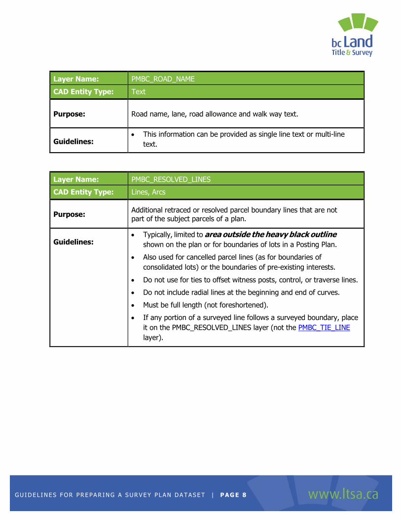
Layer Name: PMBC_ROAD_NAME
CAD Entity Type: Text
Purpose:
Road name, lane, road allowance and walk way text.
Guidelines: This information can be provided as single line text or multi-line
text.
Layer Name: PMBC_RESOLVED_LINES
CAD Entity Type: Lines, Arcs
Purpose:
Additional retraced or resolved parcel boundary lines that are not part of the subject parcels of a plan.
Guidelines: Typically, limited to area outside the heavy black outline
shown on the plan or for boundaries of lots in a Posting Plan.
Also used for cancelled parcel lines (as for boundaries of
consolidated lots) or the boundaries of pre-existing interests.
Do not use for ties to offset witness posts, control, or traverse lines.
Do not include radial lines at the beginning and end of curves.
Must be full length (not foreshortened).
If any portion of a surveyed line follows a surveyed boundary, place
it on the PMBC_RESOLVED_LINES layer (not the PMBC_TIE_LINE
layer).
G U I D E L I N ES F OR PR E PA R IN G A S UR V EY P LA N D A TA S ET | P AG E 9
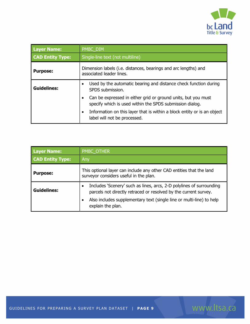
Layer Name: PMBC_DIM
CAD Entity Type: Single-line text (not multiline)
Purpose:
Dimension labels (i.e. distances, bearings and arc lengths) and associated leader lines.
Guidelines: Used by the automatic bearing and distance check function during
SPDS submission.
Can be expressed in either grid or ground units, but you must
specify which is used within the SPDS submission dialog.
Information on this layer that is within a block entity or is an object
label will not be processed.
Layer Name: PMBC_OTHER
CAD Entity Type: Any
Purpose:
This optional layer can include any other CAD entities that the land surveyor considers useful in the plan.
Guidelines: Includes ‘Scenery’ such as lines, arcs, 2-D polylines of surrounding
parcels not directly retraced or resolved by the current survey.
Also includes supplementary text (single line or multi-line) to help
explain the plan.
G U I D E L I N ES F OR PR E PA R IN G A S UR V EY P LA N D A TA S ET | P AG E 1 0
Ensuring Plan Integrity
The linework on PMBC layers in the CAD file should directly correspond to the
labeled dimensions shown on the official plan of record. If you inverse between
the endpoints of a line in the CAD file, you should get the bearing and distance labeled
in the plan (corrected for Combined Scale Factor and/or astronomic to grid bearing
convergence angle).
Surveyed lines, arcs, and natural boundary polylines should be broken into individual
segments wherever they intersect with another surveyed boundary. This does not
include tie lines (on the PMBC_TIE_LINE layer) which are expected to cross other lines
and boundaries without being broken. Surveyed boundary lines should also not be
broken where they intersect unsurveyed 'scenery' lines on the PMBC_OTHER layer.
All lines, curves and polylines on PMBC layers should 'snap' to each other
perfectly, with no overshoots (lines that cross over each other) nor gaps (lines that do
not quite meet at the parcel corner).
If linework in the official plan of record has been 'clipped' to the outline of a placed
survey post symbol (i.e. in order to 'mask' them), ensure that the lines have been
extended to their true intersection in the PMBC layers.
Always use polylines to represent natural boundaries in a plan; never use them
for surveyed (linear) boundaries.
Do not exaggerate or foreshorten lines included in PMBC layers – as specified
above, all lines should be shown at their true length and bearing in UTM grid units.
All linework included on PMBC layers should be at the same scale – do not
include details at a different scale than the main drawing.
Do not include overlapping or duplicate lines – there should only be one line
connecting any two point locations on PMBC layers
Ties to witness posts that are offset from the actual parcel boundary do not need
to be included unless they are necessary to connect the parcels to control (deleting short
tie lines to offset witness posts is recommended but not required).
G U I D E L I N ES F OR PR E PA R IN G A S UR V EY P LA N D A TA S ET | P AG E 1 1
Dimensions for witness posts that fall on parcel boundaries are not required. The goal of
ParcelMap BC is to represent the location of true parcel corners, not the location of physical
survey monuments that reference those parcel corners (merging linework to include
witness distances in the total line length is recommended but not required).
Radial lines at the beginning and end of curve are not required.
G U I D E L I N ES F OR PR E PA R IN G A S UR V EY P LA N D A TA S ET | P AG E 1 2
Instructions for Special Plan Types
Please reference Practice Bulletin No 3: Surveyor General’s Requirements for the Submission
of a Survey Plan Dataset to Support ParcelMap BC.
Explanatory Plans
Posting Plans
Building Strata Plans
Air Space, Volumetric Space and Building Lease Plans
External References
Plans Prepared in Grid distances (ABCLS Exemption under GSIR 3-4(1)(h))
Explanatory Plans
The georeferencing requirements for survey plan dataset (SPDS) submissions for Explanatory
plans are outlined in Section 5(b) of Practice Bulletin No 3: Surveyor General’s Requirements
for the Submission of a Survey Plan Dataset to Support ParcelMap BC.
If the Explanatory plan is prepared as part of a larger survey that has been
georeferenced according to the instructions in Parts 2-6 of the GSIR, use the
same georeferencing applied in that survey.
o The SPDS for the Explanatory plan should only include (on PMBC Layers) the
parcel or interest lines specific to the subject parcels of the Explanatory plan,
along with resolved lines necessary to tie the subject parcel to the underlying
georeferenced parcels. It is not necessary to include all the parcel lines from
the underlying survey.
If the plan is being approximately georeferenced from the ParcelMap BC Fabric: o Download the existing Parcel Fabric for area covered by the explanatory plan
through MyLTSA Surveyor Search and Download
o Choose a boundary line that is common to both the explanatory plan being prepared, and the downloaded fabric, to use as a reference baseline for bearing and scale
G U I D E L I N ES F OR PR E PA R IN G A S UR V EY P LA N D A TA S ET | P AG E 1 3
o Shift/translate the CAD linework to one end of the selected baseline, in order to
approximately georeference the CAD drawing to UTM coordinates.
o Rotate the CAD linework to align with the selected baseline, in order to establish approximate grid bearings for the drawing. If a true Combined Scale Factor for the area can be calculated, or derived from nearby control or georeferenced plans already in the Parcel Fabric:
• scale the drawing to UTM grid distances using that scale factor o If Combined Scale Factor is not known:
• use the length of the selected baseline to approximately scale the drawing to UTM grid distances
It is not necessary to include a Control .csv file for the selected PMBC parcel
point(s) used to georeference the plan\
When specifying the Relative Survey Accuracy of an Explanatory Plan in a Survey Plan
Submission, use Level 6 (+/- 1m / 3600" /1000PPM) unless it is part of a larger survey
that has been accurately georeferenced (in the latter case, specify the same accuracy as
the rest of the survey)
G U I D E L I N ES F OR PR E PA R IN G A S UR V EY P LA N D A TA S ET | P AG E 1 4
Posting Plans
SPDS CAD files for Posting Plans should contain no linework on the
PMBC_PARCEL_LINE or PMBC_INTEREST_LINE layer.
All resolved or retraced boundaries should be on the PMBC_RESOLVED_LINES
layer, whether or not they belong to the subject parcel(s) of the Posting Plan.
Building Strata Plans
General instructions for the preparation of SPDS CAD Files for Building Strata, Air Space, and
Volumetric Space plans are outlined in Section 5(b) of Practice Bulletin No 3: Surveyor
General’s Requirements for the Submission of a Survey Plan Dataset to Support ParcelMap BC.
(see Note at bottom)
Include the perimeter boundary of the bare land extent of the strata development on
the PMBC_PARCEL_LINE layer (typically, this is what is shown with a heavy black
outline on the official plan of record).
For Phased strata developments, only include the perimeter boundary of the current
phase of the strata development on the PMBC_PARCEL_LINE layer (if the boundaries
of previous phases have been resolved as part of the survey, include them on the
PMBC_RESOLVED_LINES layer).
Do not include any building outlines or offset lines to the building on any PMBC layers.
Do not include interior divisions of the strata development, including individual
Common Property areas or individual Strata Lots, on any PMBC layers.
Air Space, Volumetric Interest and Building Lease Plans
General instructions for the preparation of SPDS CAD Files for Building Strata, Air Space, and
Volumetric Space plans are outlined in Section 5(b) of Practice Bulletin No 3: Surveyor
General’s Requirements for the Submission of a Survey Plan Dataset to Support ParcelMap BC
G U I D E L I N ES F OR PR E PA R IN G A S UR V EY P LA N D A TA S ET | P AG E 1 5
Within ParcelMap BC, three dimensional parcels and interests (including spaces
defined by floors or levels within a building) are depicted as a schematic
representation , using he geometry of the parent parcel.
o For an Air Space parcel: include the perimeter boundary of the parent parcel
on the PMBC_PARCEL_LINE layer.
o For a Volumetric Easement, Volumetric SRW, Building Lease, or any other
interest with a three dimensional component: include the perimeter boundary
of the titled parcel over which the charge is being raised on the
PMBC_INTEREST_LINE layer.
Do not include any interior divisions of an Air Space, Volumetric Interest or Building
Lease on any PMBC layer.
For Building Lease plans: do not include any building outlines or offset lines to the building on any PMBC layers.
Note that the plan type for a Volumetric interest (including a Lease of a Building) in
your Survey Plan Submission should be Section 99 – Volumetric (not Section 99 –
Charge).
If the parent parcel boundaries were not entirely resolved during the survey of the volumetric space, provide the best available representation of the parent parcel on the PMBC_PARCEL_LINE (for an Air Space) or PMBC_INTEREST_LINE (for Volumetric Interests) layer:
o In the case of a parent that is separated into a number of distinct parts, use the perimeter boundary of the local part over which the Air Space or Volumetric Interest lies
o Scenery linework, or linework copied from another plan, can be used to represent the parent if necessary. In such cases, the Accuracy of the Survey Plan Submission should be defined as Level 6 (+/- 1m / 3600" /1000PPM) to indicate that not all parcel boundaries have been accurately resolved
G U I D E L I N ES F OR PR E PA R IN G A S UR V EY P LA N D A TA S ET | P AG E 1 6
Plans Prepared in Grid distances (ABCLS Exemption under GSIR 3-
4(1)(h))
It is still necessary to provide an Average Combined Scale factor in the Survey Plan Submission. PMBC stores parcel geometry in grid coordinates but applies a CSF to calculate ground distances for the entire fabric
Ensure that the supplied CSF is in the ground-to-grid direction, not the grid-to-ground direction
External References
A-1 Association of BCLS: General Survey Instruction Rules V3.11 – July 2016
A-2 Surveyor General Circular Letters, LTSA, specifically Circular Letter No. 463: Official Horizontal Datums for Georeferencing Legal Surveys in British Columbia
A-3 Practice Bulletin No 3: Surveyor General’s Requirements for the Submission of a Survey Plan Dataset to Support ParcelMap BC
A-4 Parcel Map BC: PMBC-RS-53-6939 Survey Plan Dataset Specifications
G U I D E L I N ES F OR PR E PA R IN G A S UR V EY P LA N D A TA S ET | P AG E 1 7
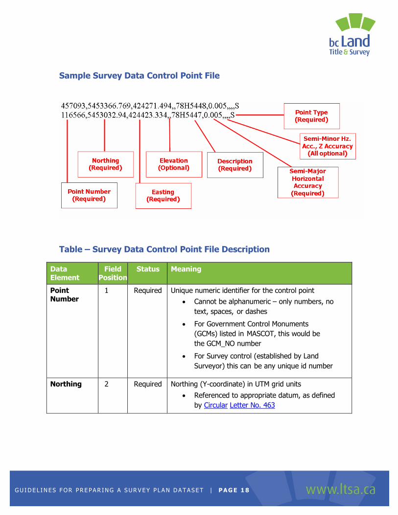
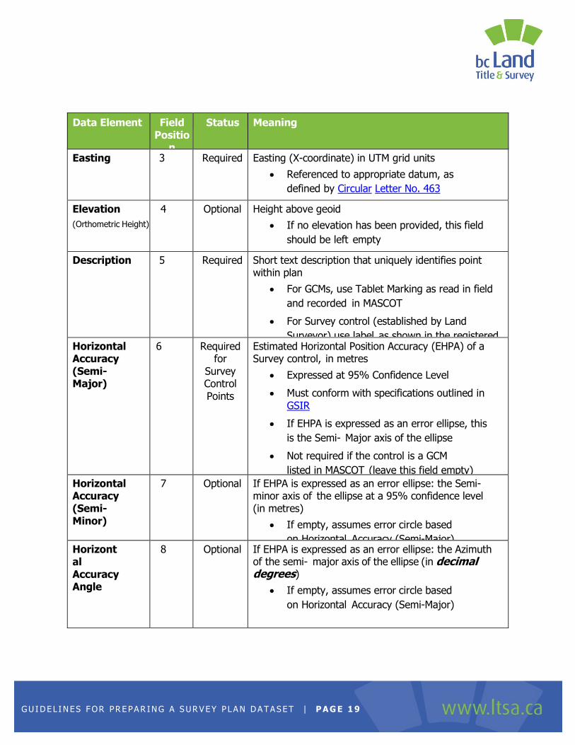
OPTIMIZING THE SURVEY DATA CONTROL POINT FILE
A .csv (comma-separated value) formatted text file describing the required geo-
referenced control points must be included:
The file name must be saved with a .csv extension.
The structure of the file is based on a standard PNEZD points file, with the
addition of extra fields to record information about the Positional Accuracy of the
control point.
Each line in the file must contain exactly ten (10) comma-separated fields,
even if no value is provided. The table below describes the content of these fields.
Do not include a header line in the file – only include the actual control point data.
The Control points for a survey plan submission are the (minimum) two
georeferenced points required under GSIR rule 2-6(1).
o Do not include any control points that are not shown within the official plan
of record.
o Do not include coordinates of survey posts (such as iron pins, lead plugs, or capped posts) unless they are labelled in the plan.Do not include the coordinates of an Active Control GNSS Reference Station.
Additional details about control point requirements can be found in the following references:
o Section 7 of Surveyor General’s Requirements for the Submission of a
Survey Plan Dataset to Support ParcelMap BC
o Parts 2-6 of General Survey Instruction Rules V3.11 – July 2016
o Circular Letter No. 463: Official Horizontal Datums for Georeferencing