Abstract: This paper presents and analyzes configurations of waveguides composed by both, regular dielectrics and negative-index materials disposed in an anti-symmetric way with respect to the optical axis. In its basic form, the configuration includes two guiding layers and two cladding media, where both the cladding and the guiding pairs have opposite-signed refractive index. A geometrical analysis shows that paths are closed, hinting the possibility of localized modes or light trapping with zero ray velocity. The ray model shows also a quasi-perfect imaging effect for off-axis objects. A modal approach shows that trapping is broadband and the propagation constant spectrum is continuous. When cores are allowed different widths, control of the group velocity is possible. More general anti-symmetrically mirrored layouts are also addressed.
1. J. B. Pendry, “Negative refraction makes a perfect lens,” Phys. Rev. Lett. 85(18), 3966–3969 (2000). 2. V. R. Shalaev, “Optical negative-index metamaterials,” Nat. Photonics 1(1), 41–48 (2007). 3. S. Zhang, W. Fan, N. C. Panoiu, K. J. Malloy, R. M. Osgood, and S. R. J. Brueck, “Experimental demonstration
of near-infrared negative-index metamaterials,” Phys. Rev. Lett. 95(13), 137404 (2005). 4. G. Dolling, M. Wegener, C. M. Soukoulis, and S. Linden, “Negative-index metamaterial at 780 nm wavelength,”
Opt. Lett. 32(1), 53–55 (2007). 5. I. V. Shadrivov, A. A. Sukhorukov, and Y. S. Kivshar, “Guided modes in negative-refractive-index waveguides,”
Phys. Rev. E Stat. Nonlin. Soft Matter Phys. 67(5), 057602 (2003). 6. K. L. Tsakmakidis, C. Hermann, A. Klaedtke, C. Jamois, and O. Hess, “Surface plasmon polaritons in
generalized slab heterostructures with negative permittivity and permeability,” Phys. Rev. B 73(8), 085104 (2006).
7. Z. H. Wang, Z. Y. Xiao, and S. P. Li, “Guided modes in slab waveguides with a left-handed material cover or substrate,” Opt. Commun. 281(4), 607–613 (2008).
8. J. He, Y. Jin, Z. Hong, and S. He, “Slow light in a dielectric waveguide with negative-refractive-index photonic crystal cladding,” Opt. Express 16(15), 11077–11082 (2008).
9. J. He, and S. He, “Slow propagation of electromagnetic waves in a dielectric slab waveguide with a left handed material substrate,” IEEE Microw. Wirel. Compon. Lett. 16(2), 96–98 (2006).
10. Y. He, Z. Cao, and Q. Shen, “Guided optical modes in asymmetric left-handed waveguides,” Opt. Commun. 245(1-6), 125–135 (2005).
11. K. L. Tsakmakidis, A. D. Boardman, and O. Hess, “Trapped rainbow' storage of light in metamaterials,” Nature 450(7168), 397–401 (2007).
12. A. Alù and N.Engheta, “Guided Modes in a Waveguide Filled With a Pair of Single-Negative (SNG), Double-Negative (DNG), and/or Double-Positive (DPS) Layers,” IEEE Trans. MTT, V.52, No. 1, 2004.
13. A. Wicht, K. Danzmann, M. Fleischhauer, M. Scully, G. Müllera, and R. H. Rinkleff, “White-light cavities, atomic phase coherence, and gravitational wave detectors,” Opt. Commun. 134(1-6), 431–439 (1997).
14. G. S. Pati, M. Salit, K. Salit, and M. S. Shahriar, “Demonstration of a tunable-bandwidth white-light interferometer using anomalous dispersion in atomic vapor,” Phys. Rev. Lett. 99(13), 133601 (2007).
15. M. J. Adams, An Introduction to optical waveguides, (Wiley, 1981)
1. Introduction
Negative refractive index materials (NIM) have being continuously promoting investigation over past years due to a host of remarkable effects, starting with the perfect imaging property
#131170 - $15.00 USD Received 6 Jul 2010; revised 12 Aug 2010; accepted 13 Aug 2010; published 15 Sep 2010(C) 2010 OSA 27 September 2010 / Vol. 18, No. 20 / OPTICS EXPRESS 20681
pointed out by Pendry [ 1]. Extensive experimental work is being carried at the present in order to artificially synthesize meta-materials with programmable optical parameters [2], and advances in micro-fabrication are pushing the realization of these materials at shorter wavelengths down to the near infra-red and visible ranges [3,4]. The source of the outstanding optical effects reported in structures containing these novel materials relies on the drastic changes in the transmission and reflection properties taking place at the interfaces between negative and positive index materials, as compared with interfaces where the two materials have permeabilities of the same sign. Waveguiding structures partially possessing negative magnetic permeabilities or electric permittivities have attracted therefore much consideration [5–10]. Special attention is being invested nowadays on the applicability of waveguides containing negative index materials for slowing-down the speed of the propagating guiding light. Structures have been proposed to slow down modes down to zero group velocity and eventually immobilize or trap optical power by suitable tapering of the waveguide's thickness [9,11]. Configurations composed by pairs of planar waveguides with materials with refractive indices of different signs surrounded by perfectly conducting plates were studied in [12] and also allow controlling and slowing down the modal group velocity. In the present article alternative structures for controlling and stopping the speed of light are proposed.
In the following sections, waveguided modes are investigated in thin films located at the transition between a positive index material and a negative index material having the same index absolute value but opposite sign (see Fig. 1). The thin films interfacing between the two materials have a raised absolute value of the refractive index providing support for propagating waveguided modes. Explicitly the electric and magnetic susceptibilities will be
designated by [(μc, εc); (μg, εg); (μg, εg); (μc, εc)], and obey:
, , , 0c g c g
g g c c
(1)
The positive and negative interfacing films thicknesses are t and s respectively. In case these two thicknesses are equal (s = t), the structure is totally anti-symmetric, or inverse-signed mirrored with respect to the plane x = 0. In the more general situation, I also analyze
the case s t, which also displays special outcomes. The analysis starts with a simple ray-optics approach to the waveguiding within the interfacing films. Ray trajectories will show the possibility of controlling the ray velocity by the asymmetry parameters, while the totally asymmetric case features zero average ray velocity and closed-loop trajectories. This structure also displays a self-imaging property, but distinctly to the thru-propagating case in NIM slabs [ 1], the image here is expected to be inverted with respect to original one. The section following presents a modal analysis of the structure. The totally anti-symmetric case (s = t) is shown to possess the exceptional property of a non-discrete (continuous) spectrum of values for the propagation constants. This configuration also supports “surface” or “SPP-type” modes, fulfilling β > ko ng. The fact that this structure supports a continuum of modes without an upper limit for the propagation constant reinforces the property of quasi-perfect imaging
deduced form the ray model. For the more general condition (s t), the eigenvalue equation for the propagation constant is also exceptionally simple and solvable. The propagation constants are now discrete and formally similar to those of a standard planar waveguide surrounded by perfect conductors, but distinctly to that case, the number of bounded modes here is reduced and depends on the refractive index of both the waveguides and claddings. The article continues with power considerations and finishes with a discussion on the connection between the modal and geometrical pictures, and an extension to more general inverse-signed mirrored configurations
2. Ray approach
Figure 1 shows ray traces for the totally antisymmetric arrangement (t = s) and for the more
general case (s t). Ray tracing is particularly simple for the given choice of refractive
#131170 - $15.00 USD Received 6 Jul 2010; revised 12 Aug 2010; accepted 13 Aug 2010; published 15 Sep 2010(C) 2010 OSA 27 September 2010 / Vol. 18, No. 20 / OPTICS EXPRESS 20682
indices, since besides the total internal reflection taking place at the interfaces between media
of the same index sign, the refraction at the z = 0 plane simply obeys the law θ1 = θ1.
Fig. 1. The basic layer disposition of material composition and thicknesses are shown for waveguide structures with opposite-signed refractive-index claddings and cores. Figure (a), (s = t) shows closed-loop ray trajectories, suggesting the possibility of localization of power. Figure (b) (s = t) shows the imaging property of this configuration. This scheme shows that rays emitted backwards also contribute to the image. In Figure (c) Quasi-circulating ray paths
for core layers of different thicknesses are seen (s t). The net ray velocity can be controlled here by the parameter s-t.
In Fig. 1(a) (t = s) rays are traced for the case of rays emerging at the x = 0 interface. The paths close back at the point of origin O, without power loss for any launching angle below
the critical angle θcr = cos1
(|nc/ng|). The ray will continue to re-circulate on that closed loop creating a sort of ring-cavity. Moreover, it is straightforward to realize that the total phase accumulated in a round trip is zero, so that the cavity will resonate for any wavelength as long as the anti-symmetric scheme is preserved. Such a cavity (“white light cavity”) was proposed more than 20 years ago [ 13] and is being object of considerably research nowadays [ 14]. The frequency regime obeying the required condition of oppositely-signed refractive indices is however always restricted by basic dispersion laws. The total zero-phase accumulation is due to the opposite sign of the refractive indices at the lower and upper portions of the path. Moreover, it is not disturbed by the Goos-Hänschen effect at the upper and lower interfaces which cancel mutually. The totally anti-symmetric sign-inverted waveguide of Fig. 1(a) presents an exceptional case where closed-ray loops can be achieved with one-dimensional (layered) structuring. Refs [ 9] and [11] also reported rays in closed loops in a tapered layout, but the condition there is based by the mutual cancellation of phases induced by propagation in the guiding layer and that induced by the Goos-Hänschen effect. On a field-type picture, one would talk here about 2D localization of light excitation in a linear 1D structure. The totally anti-symmetric scheme also displays an imaging property for off-axis objects as seen in Fig. 1(b). This property shares similarity to the well-known perfect-imaging thru-propagating case in NIM slabs [ 1], but distinctly to that case, the image here is inverted. Furthermore, in the present case also backwards-directed rays will contribute to the image, as seen by the dotted ray in Fig. 1(b). The imaging will however not be perfect here since power is lost due to finite transmission at angles beyond the critical value.
The case where the layer arrangement is not totally anti-symmetric (s t) is also of interest, and ray traces are shown in Fig. 1(c) The paths here do not close any more, but due to the quasi circulating motion, the net ray velocity component in the z direction will be reduced by the back-and-forth motion as compared to that of a normal positive-index waveguide. By simple path calculation, this velocity is explicitly given by:
( )
( / ) cos( )
z
ray g
t sv c n
t s
(2)
where θ is the launching angle. Also by simple geometry on realizes that the average power propagation direction is determined by the thicker among the two waveguide cores. One can conclude that the velocity of light and its direction can be controlled by determining the
z
#131170 - $15.00 USD Received 6 Jul 2010; revised 12 Aug 2010; accepted 13 Aug 2010; published 15 Sep 2010(C) 2010 OSA 27 September 2010 / Vol. 18, No. 20 / OPTICS EXPRESS 20683
structural parameters s and t of the composed waveguide. This conclusion is also supported by the electromagnetic modal analysis of the following section.
3. Electromagnetic modal analysis
We turn now to seek for guided confined modes in the structures of Fig. 1. As expected for one-dimensional layered medium , separated TE and TM modes are supported [ 15], and for definiteness, I will detail here the TE case only. The TM case can be straightforwardly deduced from the results obtained by dual replacement of field components and exchanging permittivites and permeabilities. The components to be considered are then of the form: (Hx,Hz,,Ey)·exp[(i(βz-ωt)], and they are inter-related by Maxwell's equations. These three field components can be therefore expressed by means of a single one, customary chosen to be Ey, and fulfilling the wave equation:
2 ( )
2 ( )
( )2
2 2
( ) ( ) ( )
( )( ) ( )
m
y m
m y
m m m
E xp E x
x
p
(3)
Here (m) denotes the layer number as shown in Fig. 1 (m = 2,-1,1,2). Continuity of the tangential electric field component Ey and the perpendicular magnetic component Hx dictate boundary conditions to be fulfilled at the three interfaces x = 0, t, -s from which the amplitude relationships of the field components are deduced. We seek at this stage for propagating confined modes fulfilling:
2 2 2
0 0s s g gk k (4)
Within this range, the modes will carry finite power and will have an exponentially decaying character at the cladding media and sinusoidal behavior at the cores. In a most general way, the modal functions can be described by the following functions:
a) At the core regions:
0 1
0 1
2 2 2
1 1 0
( ) cos( )
( ) cos( )
y g
y g
g g
E x A p x 0 < x < t
E x A p x - s < x < 0
p p p k n
(5)
b) At the cladding regions
0 1
0 1
2 2 2
2 2 0
( ) cos( )exp[ ( )]
( ) cos( )exp[ ( )]
y g c
y g c
c c
E x A p t p x t t x
E x A p s p x s x < - s
p p p k n
(6)
At x = 0, boundary conditions deduced from the opposite signs of the cores' magnetic
permeabilities (μ1 = μ1) dictate:
1 1 (7)
Boundary conditions applied also to the interfaces x = t, -s together with Eq. (7) render finally:
1 1( ) ( ) ( ) ,gp t s n n (8)
#131170 - $15.00 USD Received 6 Jul 2010; revised 12 Aug 2010; accepted 13 Aug 2010; published 15 Sep 2010(C) 2010 OSA 27 September 2010 / Vol. 18, No. 20 / OPTICS EXPRESS 20684
where n1 and n-1 are integer numbers. This simple result is rather unexpected at first sight: First one observes that Eq. (8) is independent of the cladding's permeabilities (μc, εc). This happens in spite of the fact that the modes do penetrate the clad significantly; it means that the Goos–Hänchen phases mutually cancel at the reflections in the upper and lower interfaces. Furthermore Eq. (8) is explicitly solvable for the propagation constant β. At this stage, it is worthwhile to differentiate between several cases:
3.1 Cores with different thicknesses (s t)
Keeping in mind the assumption that β is in the range: k02εcμc < β
2 < k0
2εgμg, Eq. (8) is now
identical to the dispersion equation of an equivalent simple single slab waveguide of refractive index ng and thickness | t - s | surrounded by two perfectly conducting walls. The mode
number of the equivalent slab will be N = |n1 + n-1|, and should obey N 0 for all s t. The explicit solution for the propagation constant of mode Eq. (12) is given by:
2
2 2 2
0 2
( )
( )N g
Nk n
s t
(9)
The number of guided modes M is however smaller than that of a metallic-wall equivalent guide and is given by:
2 2 1/22
{ ( ) }g cM Int s t n n
(10)
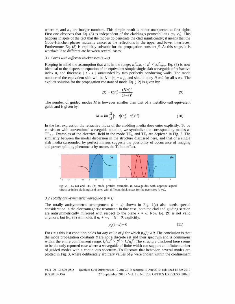
In the last expression the refractive index of the cladding media does enter explicitly. To be consistent with conventional waveguide notation, we symbolize the corresponding modes as TEN-1. Examples of the electrical field in the mode TE0, and TE1 are depicted in Fig. 2. The similarity between the modal dispersion in the structure discussed here, and that of a single slab media surrounded by perfect mirrors suggests the possibility of occurrence of imaging and power splitting phenomena by means the Talbot effect.
Fig. 2. TE0 (a) and TE1 (b) mode profiles examples in waveguides with opposite-signed
refractive index claddings and cores with different thicknesses for the two cores (s t).
3.2 Totally anti-symmetric waveguide (t = s)
The totally antisymmetric arrangement (t = s) shown in Fig. 1(a) also needs special consideration in the electromagnetic treatment. In that case, both the clad and guiding section are antisymmetrically mirrored with respect to the plane x = 0. Now Eq. (9) is not valid anymore, but Eq. (8) still holds if n1 + n-1 = N = 0, explicitly:
( ) 0gp t s (11)
For t = s this last condition holds for any value of β for which pg(β) 0. The conclusion is that the mode propagation constants β are not a discrete set and their spectrum and is continuous within the entire confinement range: k0
2nc
2 > β
2 > k0
2ng
2. The structure disclosed here seems
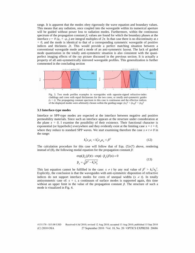
to be the only reported case where a waveguide of finite width can support an infinite number of guided modes with a continuous spectrum. To illustrate that behavior, several modes are plotted in Fig. 3, where deliberately arbitrary values of β were chosen within the confinement
#131170 - $15.00 USD Received 6 Jul 2010; revised 12 Aug 2010; accepted 13 Aug 2010; published 15 Sep 2010(C) 2010 OSA 27 September 2010 / Vol. 18, No. 20 / OPTICS EXPRESS 20685
range. It is apparent that the modes obey rigorously the wave equation and boundary values. This means that any radiation, once coupled into the waveguide within its numerical aperture will be guided without power loss to radiation modes. Furthermore, within the continuous spectrum of the propagation constant β, values are found for which the boundary phases at the interface z = 0 (φ1 = -φ-1) are integral multiples of 2π. In that case there is no discontinuity at z = 0, and the mode is identical to that of a corresponding symmetric waveguide of positive indices and thickness 2t. This would provide a perfect matching situation between a conventional waveguide mode and a mode of an anti-symmetric layout. The lack of guided mode quantization in the totally anti-symmetric situation is also consistent with the quasi-perfect imaging effects of the ray picture discussed in the previous section. It is actually a property of all anti-symmetrically mirrored waveguide profiles. This generalization is further commented in the concluding section
Fig. 3. Two mode profiles examples in waveguides with opposite-signed refractive-index claddings and cores with equal thicknesses for the two cores, or totally anti-symmetric guides (s = t). The propagating constant spectrum in this case is continuous and the effective indices of the displayed modes were arbitrarily chosen within the guiding range: (nc)
2 < (neff)2 < (ng)
2
3.3 Interface-type modes
Interface or SPP-type modes are expected at the interface between negative and positive permeability materials. Since such an interface appears at the structure under consideration at the plane x = 0, I examine the possibility of their existence. Their functional character is exponential (or hyperbolic) everywhere and they evidently exist at the limiting case s = t = 0,
where they reduce to standard SPP waves. We start examining therefore the case s t 0 in the range:
2 2 2
0 0s s g gk k (12)
The calculation procedure for this case will follow that of Eqs. (5)-(7) above, rendering instead of (8), the following modal equation for the propagation constant β:
2 2 2
0
exp( ( ) ) exp( ( ) ) 0g g
g g
p t p s
p k n
(13)
This last equation cannot be fulfilled in the case: s t by any real value of β2 > k0
2ng
2.
Explicitly, the conclusion is that the waveguides with anti-symmetric disposition of refractive
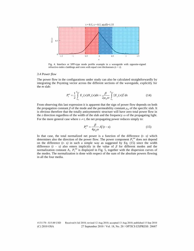
indices do not support interface modes for cores of unequal widths (s t). In totally antisymmetric case of: s = t, a continuum of surface modes is supported again, this time without an upper limit in the value of the propagation constant β. The structure of such a mode is visualized in Fig. 4.
#131170 - $15.00 USD Received 6 Jul 2010; revised 12 Aug 2010; accepted 13 Aug 2010; published 15 Sep 2010(C) 2010 OSA 27 September 2010 / Vol. 18, No. 20 / OPTICS EXPRESS 20686
Fig. 4. Interface or SPP-type mode profile example in a waveguide with opposite-signed refractive-index claddings and cores with equal core thicknesses (s = t).
3.4 Power flow
The power flow in the configurations under study can also be calculated straightforwardly by integrating the Poynting vector across the different sections of the waveguide, explicitly for the m slab:
1 1
21( ) ( ) [ ( )]
2 2
m m
m m
d d
m
z y x y
md d
P E x H x dx E x dx
(14)
From observing this last expression it is apparent that the sign of power flow depends on both the propagation constant β of the mode and the permeability constant μm of the specific slab. It is obvious therefore that the totally antisymmetric structure will have zero total power flow in the z direction regardless of the width of the slab and the frequency ω of the propagating light.
For the more general case where s t, the net propagating power reduces simply to:
2
1 ( )4
tot
z
g
P A t s
(15)
In that case, the total normalized net power is a function of the difference (t- s) which determines also the direction of the power flow. The power component Pz
tot does not depend
on the difference (t- s) in such a simple way as suggested by Eq. (15) since the width difference (t – s) also enters implicitly in the value of β for different modes and the normalization constant A1. Pz
tot is displayed in Fig. 5, together with the dispersion curves of
the modes. The normalization is done with respect of the sum of the absolute powers flowing in all the four media.
#131170 - $15.00 USD Received 6 Jul 2010; revised 12 Aug 2010; accepted 13 Aug 2010; published 15 Sep 2010(C) 2010 OSA 27 September 2010 / Vol. 18, No. 20 / OPTICS EXPRESS 20687
Fig. 5. Normalized effective indices (dashed lines) and normalized power flow in the z-direction as a function of x = (t – s), for the first two modes in a waveguide structure with parameters ng = 2 and nc = 1.7. The total width, (t + s) is kept constant at a value of 2. The inset shows an enlargement of the threshold region of the TE1 mode to emphasize that the power flow is a continuous function of (t – s)
4. Connection between the geometrical and modal pictures
As in conventional waveguides, the modal quantization and allowed values of the propagation constant can be deduced also here directly from the ray picture by adding two adjustments, namely the introduction of an “effective width” and the requirement of a transverse resonance condition. The “effective width” is a way of including the Goos-Hänschen effect, and for the waveguides discussed here this effect is of the normal type, since there are no sign changes in the permeabilities at the interface planes x = t, -s. This means that the phase jumps at reflection adds to the phase accumulated by the rays propagating at the upper and lower part of the waveguides which are mutually opposite in sign, and the conclusion is that they mutually cancel within a single loop. The clad parameters on the other side do affect the net power flow via the normalization constants. For the totally antisymmetric structures the sum of the accumulated phase is identically zero for all ray traces, and the transversal resonance condition is automatically fulfilled. This situation will hold also for general antisymmetrically mirrored multilayered structures and even for the cases where the index is graded within each of the half-planes delimited by x = 0.
5. Concluding remarks
This article presented a basic analysis of a special class of waveguides composed by both, regular dielectrics and negative-index materials. The configuration included two guiding layers and two cladding media, where both the claddings and the guiding pairs have opposite-
signed refractive indices. In the general case of different widths in the guide layers (s t), the structure allows the control of the phase and group velocities of guided radiation by changing the structural parameters. Modes within this configuration have dispersion relations which are equivalent to modes in a dielectric slab surrounded by perfect conductors. Unique is the case of totally antisymmetric structures: Here the geometrical ray paths are closed, hinting the possibility of localized modes in perfectly linear media. The ray model also shows a quasi-perfect imaging effect for off-axis objects in that case. Following an electro-magnetic approach, the modes of the totally anti-symmetric case seem exceptional in the sense that their spectrum is continuous. This property can also be translated to the frequency domain: A
#131170 - $15.00 USD Received 6 Jul 2010; revised 12 Aug 2010; accepted 13 Aug 2010; published 15 Sep 2010(C) 2010 OSA 27 September 2010 / Vol. 18, No. 20 / OPTICS EXPRESS 20688
specific anti-symmetric structure will support localized modes for a wider frequency range as long as the chromatic dispersion doesn’t destroy the asymmetry of the refractive indices. In a pictorial description one may describe this effect as “white light localization”. Structures containing both positive and negative index analyzed in the previous literature showed already the possibility of slowing-down the group velocity of light attain eventually conditions of reducing this velocity down to zero, but this was shown to happen only for a definite frequency. Slow light has been advocated as a means of storing optical power for optical processing and buffering data. In the scheme described here, the storing would be possible for multi-mode and eventually wide-band radiation. With respect to polarization, only TE modes were described, and from duality considerations, the properties of the TM counterparts can be deduced. In a case where half of the space contains double negative permeability and permittivity materials, TE and TM modes will be degenerated in their propagation constants but have distinct modal distributions. Regarding the physical realization of these effects, actual devices trying to approach the ideal conditions required here will have necessarily deviations in the asymmetry property requirements, both electrical and geometrical. Dispersion and finite losses in the materials will also disturb the strict conditions of opposite sign in the permeability constants. The propagation behavior in these non-ideal cases is worth investigating. The mathematical properties of the set of eigenmodes of the antisymmetric structure are also unusual and deserve further investigation: they possess a continuous spectrum and are evidently a non-orthogonal, yet normalizable set. The structures studied here are actually special examples of more a class of general anti-symmetrically mirrored waveguided structures, which may be composed of an arbitrarily large number of guiding layers and even be of graded-index nature.
#131170 - $15.00 USD Received 6 Jul 2010; revised 12 Aug 2010; accepted 13 Aug 2010; published 15 Sep 2010(C) 2010 OSA 27 September 2010 / Vol. 18, No. 20 / OPTICS EXPRESS 20689