Keywords: Angle shear connectors; Composite beam; Push-out test; Failure mode; load-displacement curves Abstract. The reasonable design of shear connectors is the key to ensure the integral forced performance of steel-concrete composite beam. This paper presents an experimental research on the capacity of angle shear connectors. Six push-out specimens with different height and thickness of angles were included in this experiment. The failure mode observed in all specimens was the concrete crushing splitting. All specimens had a plastic behavior under load. The results show that the main factor which influences the ultimate bearing capacity of angel shear connectors is the thickness of flange and web. Increasing the height of flange of angles could slightly raise the ultimate bearing capacity.
Introduction Steel-concrete composite beam is a new type structure which is being popularized in China [1]. It combines the characteristics of concrete and steel structure through shear connectors. The reasonable design of shear connectors is the key to ensure the integral forced performance of a structure.
Angle shear connectors belong to steel reinforced shear connectors. As shown in Fig.1, the angle steel is welded to the flange of the corrugated steel webs and each one contains a hole. In additional, U-shaped steel is welded on the angle steel.
A review of the literature indicates that there are a few researches which have been done for angle shear connectors. A research done by Zhou [2] involved testing of small size push-out specimens and theoretical deduction. An experimental investigation by Zhang [3], involving the testing of 6 specimens is focused on the behavior of the multiple angle shear connectors.
This paper presents the results of 6 push-out tests of angle shear connectors. The effects of the thickness and the height of the flange are discussed.
Fig. 1 Angle shear connectors
Experimental program Six specimens with different geometry size were considered for testing in this research. The material properties of push-out specimens are shown in Table 1. Angle steel which consist of two steel plates was welded at each flange of an I-beam. The size of each concrete slab is 875 mm × 410 mm × 250 mm.
International Forum on Energy, Environment and Sustainable Development (IFEESD 2016)
Fig. 2 orthographic views of typical test specimens
Three types of angle were used. First types (set SC-1) angle had a web and flange thickness of 10mm with 100mm in height. Second type (set SC-2) angle with the same thickness as set SC-1 had a 100mm web in height, while flange is 160mm in height. Angles of which web and flange were 100mm in height and 16mm in thickness were used in the Last set SC-3. The width of all three types of angles was 200mm. Some reinforcement was embedded in concrete. The details of specimens are presented in Table 2. Fig. 2 is the orthographic views of typical test specimens. One of the specimens is shown in Fig. 3.
A 5000kN electro-hydraulic servo universal testing machine shown in Fig. 4 was used for load application, with a portable data logger and four displacement meters to record the relative displacement between I-beam and concrete slabs. Load was applied thought the bottom of the two concrete slabs, and the top of I-beam was supported by a plate. Step loading was employed and force was increased 50kN per step.
197
Table 2 Material properties of push-out specimens
Set Size of Angles Diameter of holes Diameter of perforating rebar
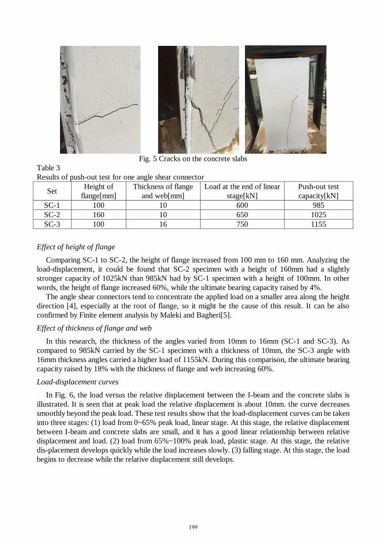
The failure mode found in all three sets of specimens was the concrete crushing splitting. The feature of this failure type could be described as follow. When the force is up to about 60% ultimate load, a horizontal crack appeared on the sides of the specimen. With force increasing, diagonal cracks were observed on the sides of the specimen and a vertical crack developing from the bottom of concrete slabs could be found on the outside of the specimen. This type of failure was illustrated in Fig. 5. All specimens had a plastic behavior under load. The results of the push-out tests are presented in Table 3, and all results for shear capacity are presented for one angle shear connector.
198
Fig. 5 Cracks on the concrete slabs
Table 3 Results of push-out test for one angle shear connector
Comparing SC-1 to SC-2, the height of flange increased from 100 mm to 160 mm. Analyzing the load-displacement, it could be found that SC-2 specimen with a height of 160mm had a slightly stronger capacity of 1025kN than 985kN had by SC-1 specimen with a height of 100mm. In other words, the height of flange increased 60%, while the ultimate bearing capacity raised by 4%.
The angle shear connectors tend to concentrate the applied load on a smaller area along the height direction [4], especially at the root of flange, so it might be the cause of this result. It can be also confirmed by Finite element analysis by Maleki and Bagheri[5].
Effect of thickness of flange and web
In this research, the thickness of the angles varied from 10mm to 16mm (SC-1 and SC-3). As compared to 985kN carried by the SC-1 specimen with a thickness of 10mm, the SC-3 angle with 16mm thickness angles carried a higher load of 1155kN. During this comparison, the ultimate bearing capacity raised by 18% with the thickness of flange and web increasing 60%.
Load-displacement curves
In Fig. 6, the load versus the relative displacement between the I-beam and the concrete slabs is illustrated. It is seen that at peak load the relative displacement is about 10mm. the curve decreases smoothly beyond the peak load. These test results show that the load-displacement curves can be taken into three stages: (1) load from 0~65% peak load, linear stage. At this stage, the relative displacement between I-beam and concrete slabs are small, and it has a good linear relationship between relative displacement and load. (2) load from 65%~100% peak load, plastic stage. At this stage, the relative dis-placement develops quickly while the load increases slowly. (3) falling stage. At this stage, the load begins to decrease while the relative displacement still develops.
199
(a) SC-1 (b) SC-2
(c) SC-3
Fig. 6 Load-displacement curves of specimens
Conclusions In this paper the results of 6 push-out tests of angle shear connectors to research the effects of the thickness and the height of angles were reported. The conclusions obtained are that:
(1) The failure mode observed in all specimens was the concrete crushing splitting. All specimens had a plastic behavior under load.
(2) The load-displacement curve of angle shear connectors can be taken into three stages: linear stage, plastic stage and falling stage.
(3) The main factor which influences the ultimate load capacity of angel shear connectors is the thickness of flange and web. Increasing the height of flange of angles could slightly raise the ultimate bearing capacity.
References
[1] L. Shuqin, C. Jianbin, W. Shui, C. Huali: Engineering Mechanics Vol. 26 (2009), p. 115 In Chinese
[2] Z. Weide, B. Jianan, L. Yuantie, W. Xiaoyi: Journal of Hefei University of Technology Vol. 17 (1994), p. 126 In Chinese
[3] Z. Zhihui, H. Shuanhai, Y. Lei, M. Yunfei: Journal of Hefei University of Technology Vol. 37 (2014), p. 1346 In Chinese
[4] M. Shariati, A. Shariati, N.R. Sulong, M. Suhatril and M.A. Khanouki: Engineering Failure Analysis Vol. 41 (2014), p. 123
[5] S. Maleki, S. Bagheri: Journal of Constructional Steel Research Vol. 64 (2008), p. 1333