This guide presents the instructions and other information concerning the lab activities for thiscourse. You can find the solutions in the lab activity Answer Key.
Outline
This guide includes these activities:
Lab Overview
Lab 1-1: Implementing H.323 Gateways
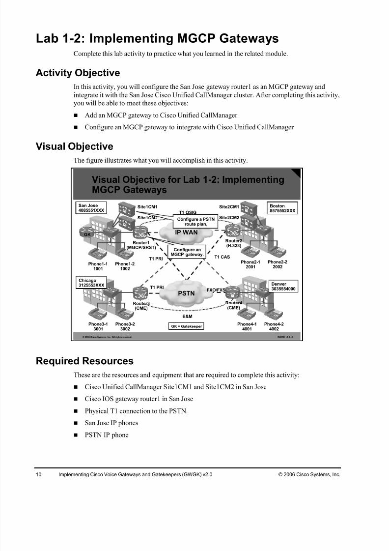
Lab 1-2: Implementing MGCP Gateways
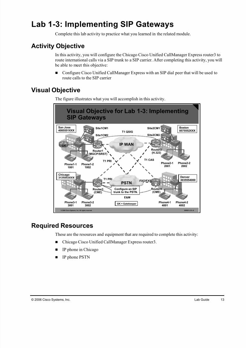
Lab 1-3: Implementing SIP Gateways
Lab 2-1: Implementing Analog Trunks
Lab 2-2: Implementing CAS Trunks
Lab 2-3: Implementing PRI Trunks
Lab 2-4: Implementing QSIG Trunks
Lab 3-1: Implementing PSTN Dial Plans on Cisco IOS Gateways
Lab 3-2: Implementing Multi-site Dial Plans on Cisco IOS Gateways
Lab 3-3: Implementing RSVP-Based CAC
Lab 3-4: Implementing Calling Privileges on Cisco IOS Gateways
Lab 4-1: Implementing SRST Gateways
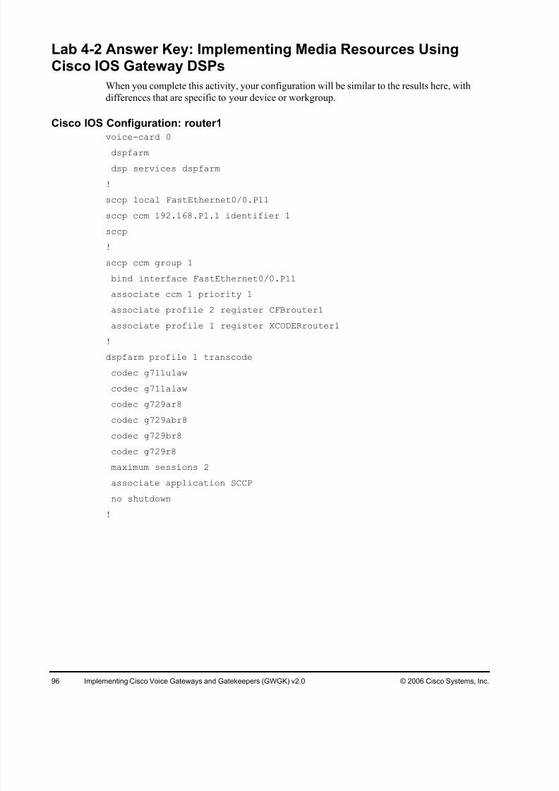
Lab 4-2: Implementing Media Resources Using Cisco IOS Gateway DSPs
Lab 4-3: Implementing Call Applications on Cisco IOS Gateways
Lab 1-1: Implementing H.323 GatewaysComplete this lab activity to practice what you learned in the related module.
Activity Objective
In this activity, you will configure the Boston gateway router2 as an H.323 gateway and
integrate it with the Boston Cisco Unified CallManager cluster, including redundant CiscoUnified CallManager connections. After completing this activity, you will be able to meet these
objectives:
Configure a H.323 gateway to integrate with Cisco Unified CallManager
Add an H.323 gateway to Cisco Unified CallManager
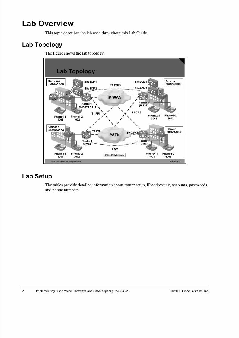
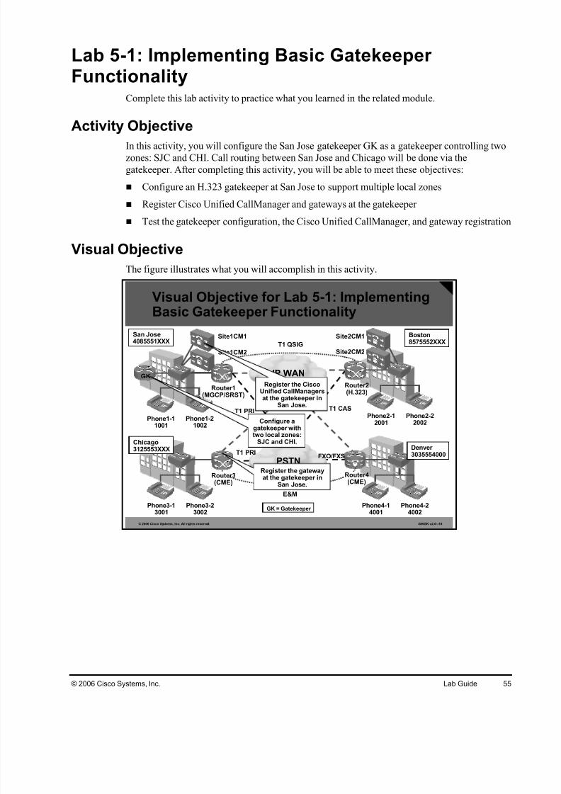
Visual Objective
The figure illustrates what you will accomplish in this activity.
Lab 2-1: Implementing Analog TrunksComplete this lab activity to practice what you learned in the related module.
Activity Objective
In this activity, you will configure an FXO PSTN trunk on the Denver Cisco Unified
CallManager Express router4. Because DID is not available, all inbound PSTN calls should berouted to the attendant with extension 4002. In addition, you will configure an E&M trunk to
route calls between Chicago router3 and Denver router4. After completing this activity, you
will be able to meet these objectives:
Configure an FXO trunk on a Cisco IOS gateway
Configure an E&M trunk on a Cisco IOS gateway
Visual Objective
The figure illustrates what you will accomplish in this activity.
The table describes the commands that are used in this activity.
Analog Voice Port Configuration Commands
Command Description
connection plar opx digits Directly routes a call from a voice port to the specifiednumber.
signal {groundStart |loopstart}
To specify the type of signaling for a voice port, use thesignal command in voice-port configuration mode. To resetto the default, use the no form of this command.
caller-id enable To allow the sending or receiving of caller-ID information,use the caller -id enable command in voice-portconfiguration mode at the sending FXS voice port or thereceiving FXO voice port. To disable the sending andreceiving of caller-ID information, use the no form of thiscommand.
E&M Configuration Commands
Command Description
type {1 | 2 | 3 | 4 | 5} To specify the E&M interface type, use the type commandin voice-port configuration mode. To reset to the default,use the no form of this command.
signal {delay-dial |immediate | lmr | wink-start}
To specify the type of signaling for a voice port, use thesignal command in voice-port configuration mode. To resetto the default, use the no form of this command.
Job Aids
This job aid is available to help you complete the lab activity:
Cisco IOS Voice Configuration Library
Task 1: Configure an FXO Trunk to the PSTN
In this task, you will configure Denver’s voice gateway for dialing into the PSTN. Incoming
calls will be routed to an attendant IP phone (ext. 4002)
Activity Procedure
Complete these steps:
Step 1 Configure the FXO PSTN trunk to use ground-start signaling.
Step 2 Create a new POTS dial peer with a destination pattern 9T to route outbound calls
using the FXO trunk. Verify that you can dial in to Denver using two-stage dialing.
Step 3 Ensure that any inbound call on the FXO trunk is routed directly to extension 4002.
Use the clock source command in controller configurationmode to set clocking for individual T1 or E1 links. To returnto the default, use the no form of this command.
network-clock-participate{aim | slot | wic} slot-
number
Use the network-clock-participate command in globalconfiguration mode to allow the ports on a specified
network module or VWIC to use the network clock for timing. To restrict the device to use only its own clocksignals, use the no form of this command.
Use the ds0-group command in controller configurationmode to specify the DS0 time slots that make up a logicalvoice port on a T1 controller, to specify the signaling typeby which the router communicates with the PBX or PSTN,and to define T1 channels for compressed voice calls andthe CAS method by which the router connects to the PBXor PSTN. To remove the group and signaling setting, usethe no form of this command.
Job Aids
These job aids are available to help you complete the lab activity.
Cisco IOS Voice Command Reference
Cisco Interface Command Reference
Task 1: Configure a CAS Trunk to the PSTN
In this task, you will configure a CAS connection to the PSTN at Boston’s voice gateway for
dialing into the PSTN. The Boston gateway is already set up as an H.323 gateway so only themissing configuration needs to be added.
The table describes the commands that are used in this activity.
T1 Interface Commands
Command Description
isdn switch-type {country-
specific-switch-type}
Defines the telephone company switch type.
interface {bri | pri}interface-number
Enters interface configuration mode.
isdn incoming-voice voice To route all incoming voice calls to the modem anddetermine how they will be treated, use the isdnincoming-voice command in interface configuration mode.To disable the setting or return to the default, use the noform of this command.
pri-group timeslotstimeslot-range [nfas_d {backup | none | primary{nfas_int number |nfas_group number | rlm-group number }} | service]
To configure NFAS and specify the channels to becontrolled by the primary NFAS D channel, use the pri-group timeslots command in controller configurationmode.
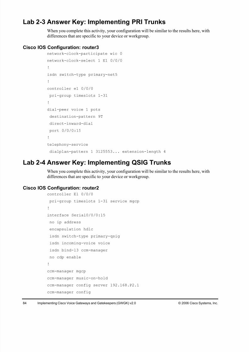
Task 1: Configure an ISDN PRI Trunk to the PSTN in Chicago
In this task, you will configure an ISDN PRI trunk connection to the PSTN on Chicago’s voice
gateways for PSTN calls.
Activity Procedure
Complete these steps:
Step 1 On the Chicago Cisco Unified CallManager Express router3, ensure that the DSPs
are correctly clocked.
Step 2 Specify the correct global ISDN switch type. Use primary-net5.
Step 3 Configure the controller of the E1 PRI PSTN trunk (E1 0/0/0). Use all available time
slots.
Step 4 Configure the ISDN signaling interface for inbound voice calls.
Step 5 Add a new dial peer with a destination pattern 9T and DID enabled. Use the E1 PRI
PSTN trunk.
Step 6 Access the Cisco Unified CallManager Express configuration mode and configure adial plan pattern that enables DID calls to the Chicago DID range.
Step 7 Verify connectivity by placing calls in both directions.
Activity Verification
You have completed this task when you attain these results:
Lab 2-4: Implementing QSIG TrunksComplete this lab activity to practice what you learned in the related module.
Activity Objective
In this activity, you will configure a E1 QSIG trunk between San Jose and Boston. The San
Jose MGCP gateway router1 will be the network side of the connection and the Boston gatewayrouter2 configured as an H.323 gateway will also be added as an MGCP gateway to the Boston
Cisco Unified CallManager cluster. After completing this activity, you will be able to meet
these objectives:
Configure Cisco Unified CallManager QSIG PRI trunks for interconnection
Configure Cisco Unified CallManager settings for callback
Verify the correct operation
Visual Objective
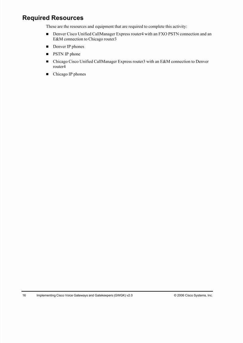
The figure illustrates what you will accomplish in this activity.
The tables describe the commands that are used in this activity.
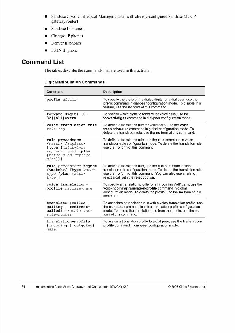
Digit Manipulation Commands
Command Description
digit-strip Digit stripping strips all the digits that explicitly match a POTS dialpeer. Digit stripping is enabled by default on POTS dial peers.
prefix digits To specify the prefix of the dialed digits for a dial peer, use theprefix command in dial-peer configuration mode. To disable thisfeature, use the no form of this command.
forward-digits [0-32]|all|extra
To specify which digits to forward for voice calls, use theforward-digits command in dial-peer configuration mode.
num-exp dialed-digitssubstitution
To define how to expand a telephone extension number into aparticular destination pattern, use the num-exp command inglobal configuration mode. To cancel the configured number expansion, use the no form of this command.
voice translation-rule
rule tag
To define a translation rule for voice calls, use the voice
translation-rule command in global configuration mode. Todelete the translation rule, use the no form of this command.
To define a translation rule, use the rule command in voicetranslation-rule configuration mode. To delete the translation rule,use the no form of this command.
To define a translation rule, use the rule command in voicetranslation-rule configuration mode. To delete the translation rule,use the no form of this command. You can also use a rule toreject a call by using the reject option.
voice translation- profile profile-name
To specify a translation profile for all incoming VoIP calls, use thevoip-incoming translation-profile command in globalconfiguration mode. To delete the profile, use the no form of thiscommand.
To associate a translation rule with a voice translation profile, usethe translate command in voice translation-profile configurationmode. To delete the translation rule from the profile, use the no form of this command.
translation-profile{incoming | outgoing}name
To assign a translation profile to a dial peer, use the translation-profile command in dial-peer configuration mode.
test voicetranslation-rule
number input-test-string [type match-type [plan match-type]
To test the functionality of a translation rule, use the test voicetranslation-rule command in privileged EXEC mode.
To specify either the prefix or the full E.164 telephone number tobe used for a dial peer, use the destination-pattern command indial-peer configuration mode. To disable the configured prefix or telephone number, use the no form of this command.
incoming called-number[+]string [T]
To specify a digit string that can be matched by an incoming callto associate the call with a dial peer, use the incoming called-number command in dial-peer configuration mode. To reset tothe default, use the no form of this command.
answer-address[+]string [T]
To specify the full E.164 telephone number to be used to identifythe dial peer of an incoming call, use the answer-address command in dial-peer configuration mode. To disable theconfigured telephone number, use the no form of this command.
direct-inward-dial Use the direct-inward-dial command to enable the DID calltreatment for an incoming called number.
preference [0-9] To indicate the preferred order of a dial peer within a hunt group,use the preference command in dial-peer configuration mode.
no dial-peer outbound
status-check pots
To check the status of outbound POTS dial peers during callsetup and to disallow, for that call, any dial peers whose status isdown, use the dial-peer outbound status-check pots commandin privileged EXEC mode. To disable status checking, use the no form of this command.
Job Aids
This job aid is available to help you complete the lab activity.
Voice configuration library on Cisco.com
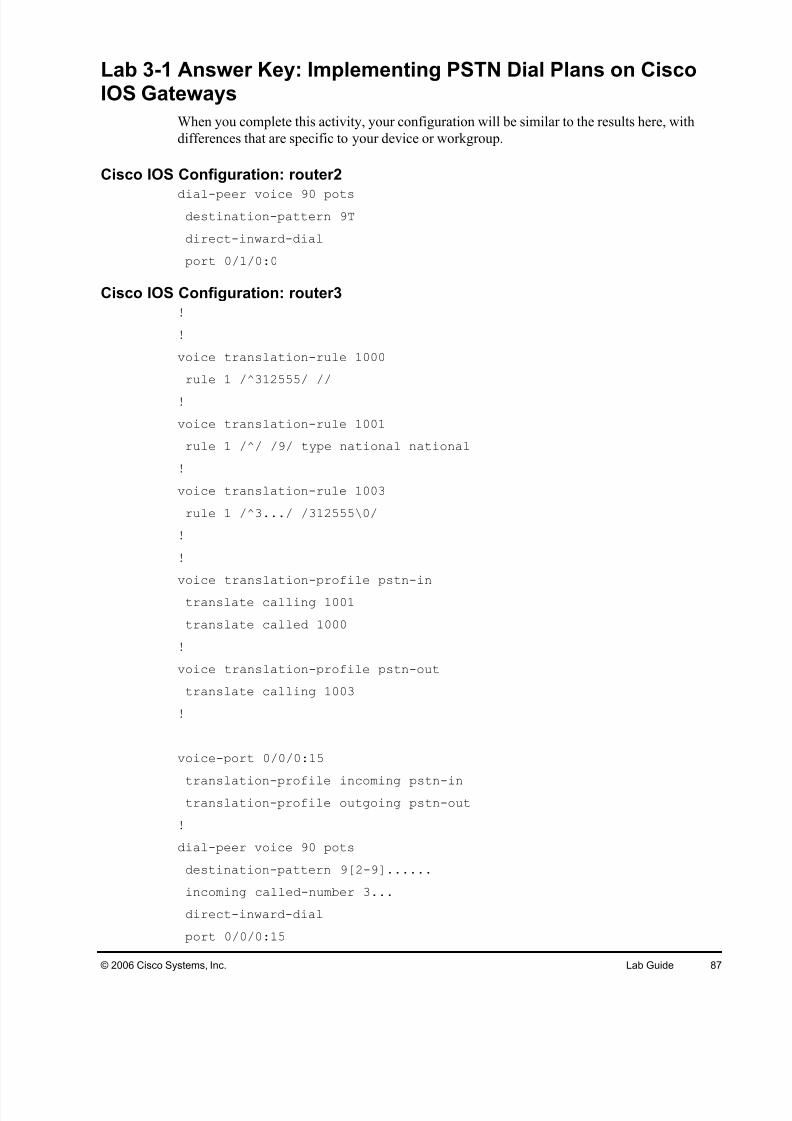
Task 1: Configure Dial Peers for Inbound and Outbound PSTNRouting
In this task, you will configure dial peers for inbound and outbound PSTN routing on the
Boston H.323 gateway router2, Chicago Cisco Unified CallManager Express router3, and
Denver Cisco Unified CallManager Express router4.
Activity Procedure
Complete these steps:
Step 1 On the Boston H.323 gateway router2, Chicago Cisco Unified CallManager Express
router3, and Denver Cisco Unified CallManager Express router4, remove any
existing dial peer configuration used for PSTN routing.
Step 2 On the Boston H.323 gateway router2, Chicago Cisco Unified CallManager Expressrouter3, and Denver Cisco Unified CallManager Express router4, verify that the
controllers and voice ports are configured correctly.
Step 3 On the Boston H.323 gateway router2, configure this POTS dial peer:
The called DID numbers 3125553XXX should be cut down to the four-digit
extension. For example, 3125553001 should be modified to 3001.
Step 2 Remove any existing dial plan pattern configuration
Step 3 Bind the voice translation profile pstn-in to the E1 PRI PSTN trunk. The profile
should be applied to incoming calls. Verify that inbound PSTN calls are working
again.
Step 4 Configure a voice-translation profile pstn-out that performs this digit manipulation: The calling number 3XXX should be prefixed with the Chicago DID range
312555. For example, if a call is placed from phone 3-1, the calling number
should be modified from 3001 to 3125553001.
Step 5 Bind the voice translation profile pstn-out to voice port 0/0/0:15. The ANI should
now be correctly modified to include the DID range for outgoing calls.
Activity Verification
You have completed this task when you attain these results:
Inbound calls to Chicago router 3 should be possible without the dialplan-pattern
command.
Inbound calls to Chicago router 3 include the 9 in the calling number. For example, a call
from the PSTN 13125556666 to Chicago phone 3-1 should be displayed as 913125556666.
Outbound calls from Chicago router 3 should have the calling number 3125553XXX.
San Jose Cisco Unified CallManager cluster with already-configured San Jose MGCP
gateway router1
San Jose IP phones
Chicago IP phones
Denver IP phones
PSTN IP phone
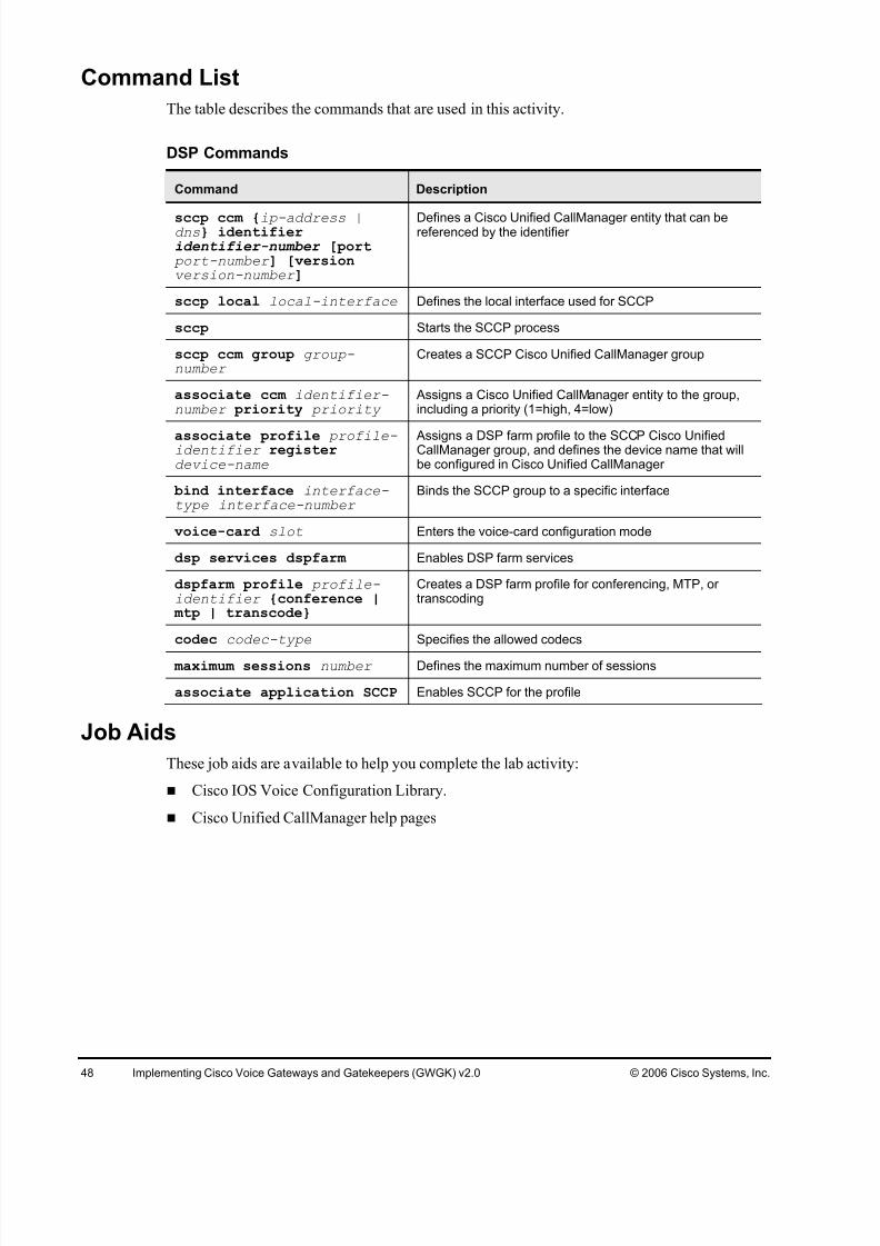
Command List
The tables describe the commands that are used in this activity.
Digit Manipulation Commands
Command Description
prefix digits To specify the prefix of the dialed digits for a dial peer, use theprefix command in dial-peer configuration mode. To disable thisfeature, use the no form of this command.
forward-digits [0-32]|all|extra
To specify which digits to forward for voice calls, use theforward-digits command in dial-peer configuration mode.
voice translation-rulerule tag
To define a translation rule for voice calls, use the voicetranslation-rule command in global configuration mode. Todelete the translation rule, use the no form of this command.
To define a translation rule, use the rule command in voicetranslation-rule configuration mode. To delete the translation rule,use the no form of this command.
rule precedence reject/<match>/ [type match-
type [plan match-type]]
To define a translation rule, use the rule command in voicetranslation-rule configuration mode. To delete the translation rule,
use the no form of this command. You can also use a rule toreject a call with the reject option.
voice translation- profile profile-name
To specify a translation profile for all incoming VoIP calls, use thevoip-incoming translation-profile command in globalconfiguration mode. To delete the profile, use the no form of thiscommand.
To associate a translation rule with a voice translation profile, usethe translate command in voice translation-profile configurationmode. To delete the translation rule from the profile, use the no form of this command.
translation-profile{incoming | outgoing}name
To assign a translation profile to a dial peer, use the translation-profile command in dial-peer configuration mode.
To specify either the prefix or the full E.164 telephone number tobe used for a dial peer, use the destination-pattern command indial-peer configuration mode. To disable the configured prefix or telephone number, use the no form of this command.
preference [0-9] To indicate the preferred order of a dial peer within a hunt group,use the preference command in dial-peer configuration mode.
voice class h323 tag To create an H.323 voice class that is independent of a dial peer and can be used on multiple dial peers, use the voice classh323 command in global configuration mode. To remove thevoice class, use the no form of this command.
h225 timeout tcpestablish seconds
To set the H.225 TCP timeout value for VoIP dial peers, use theh225 timeout tcp establish command in voice-classconfiguration mode. To reset to the default, use the no form of this command.
Job Aids
This job aid is available to help you complete the lab activity.
Voice configuration library on Cisco.com
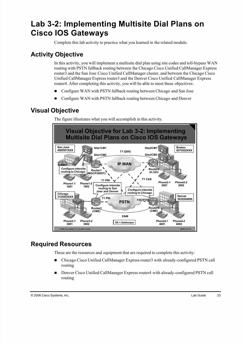
Task 1: Configure WAN with PSTN Fallback Routing BetweenChicago and San Jose
In this task, you will configure WAN routing between the Chicago Cisco Unified CallManager
Express router3 and the San Jose Cisco Unified CallManager cluster, including PSTN fallback
routing.
Activity Procedure
Complete these steps:
Step 1 On the Chicago Cisco Unified CallManager Express router3, configure these dial
Lab 3-3: Implementing RSVP-Based CACComplete this lab activity to practice what you learned in the related module.
Activity Objective
In this activity, you will implement RSVP-based CAC between the Chicago Cisco Unified
CallManager Express router3 and the Denver Cisco Unified CallManager Express router4.After completing this activity, you will be able to meet this objective:
Configure RSVP-based CAC on Cisco IOS gateways for VoIP calls
Visual Objective
The figure illustrates what you will accomplish in this activity.
The table describes the commands that are used in this activity.
RSVP Commands
Command Description
call rsvp-sync To enable synchronization between RSVP signaling and thevoice signaling protocol, use the call rsvp-sync command inglobal configuration mode. To disable synchronization, use theno form of this command.
ip rsvp bandwidthinterface-kbps
To specify the bandwidth available to RSVP, use the ip rsvpbandwidth command. The bandwidth should match the desirednumber of concurrent voice calls allowed over a specific link.
req-qos guaranteed-delay
To specify the desired quality of service to be used in reaching aspecified dial peer, use the req-qos command in dial-peer configuration mode. To restore the default value for thiscommand, use the no form of this command. The guaranteeddelay option indicates that RSVP should reserve bandwidth.
acc-qos guaranteed-delay
To specify the acceptable quality of service to be used in
reaching a specified dial peer, use the acc-qos command in dial-peer configuration mode. To restore the default value for thiscommand, use the no form of this command. The guaranteeddelay option indicates that RSVP should reserve bandwidth.
call rsvp-sync resv-timer seconds
To set the timer on the terminating VoIP gateway for completing RSVP reservation setups, use the call rsvp-syncresv-timer global configuration command. To restore thedefault value, use the no form of this command
Job Aids
This job aid is available to help you complete the lab activity:
The table describes the commands that are used in this activity.
COR Commands
Command Description
dial-peer cor custom Enters COR configuration mode where named CORs can bedefined.
name cor-name Use the name command in COR configuration mode to createthe named CORs.
dial-peer cor listlist-name
To define a COR list name, use the dial-peer cor list commandin global configuration mode. To remove a previously definedCOR list name, use the no form of this command.
corlist incoming cor-list-name
To specify the COR list to be used when a specified dial peer acts as the incoming dial peer, use the corlist incoming command in dial-peer configuration mode. To clear the previouslydefined incoming COR list in preparation for redefining theincoming COR list, use the no form of this command.
corlist outgoing cor-list-name
To specify the COR list to be used by outgoing dial peers, use thecorlist outgoing command in dial-peer configuration mode. Toclear the previously defined outgoing COR list in preparation for redefining the outgoing COR list, use the no form of thiscommand.
Job Aids
This job aid is available to help you complete the lab activity:
Voice configuration library on Cisco.com
Task 1: Configure Calling Privileges in Chicago
In this task, you will configure the Chicago Cisco Unified CallManager Express router3 for
calling privileges. Three different classes will be required: local, national, and international. A
user with the local class will not be able to place any national or international calls, a user with
the national class will not be able to place any international calls, and a user with the
international class will be able to place any call.
Activity Procedure
Complete these steps:
Step 1 On the Chicago Cisco Unified CallManager Express router3, verify that you have a
unique dial peer for local calls, national calls, international calls, and emergency
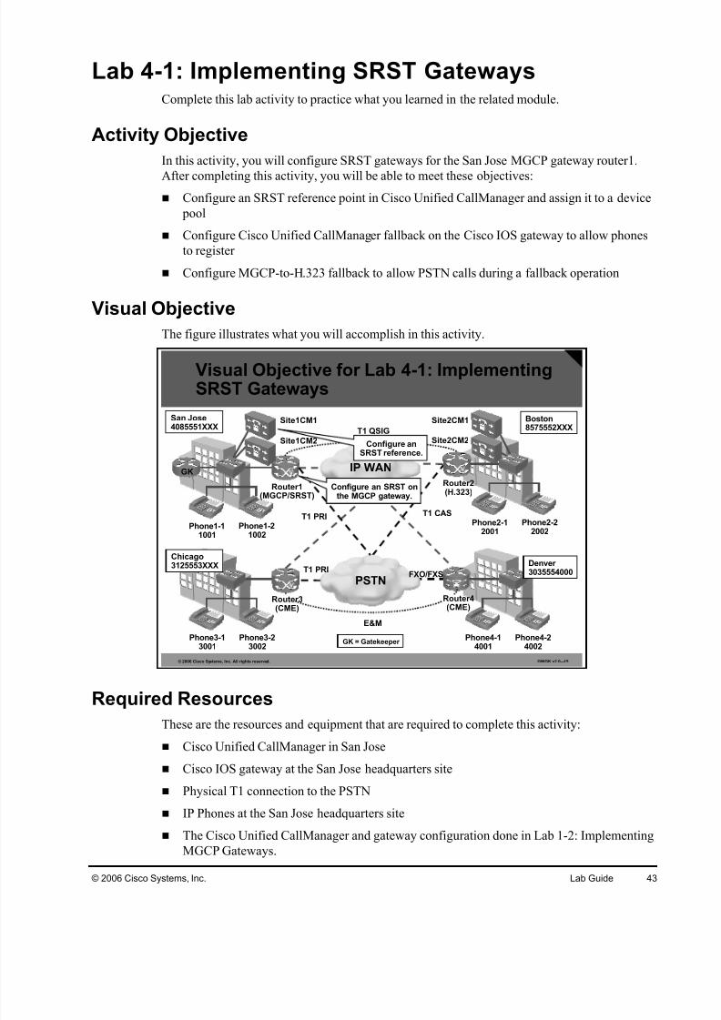
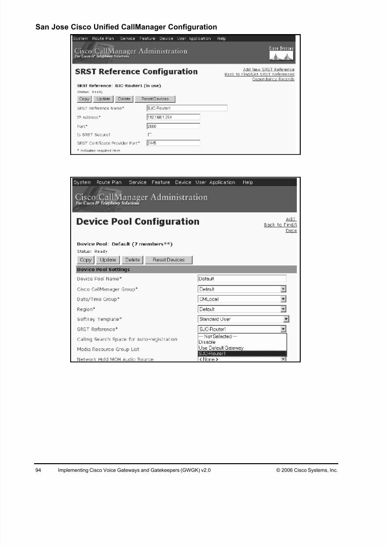
Lab 4-1: Implementing SRST GatewaysComplete this lab activity to practice what you learned in the related module.
Activity Objective
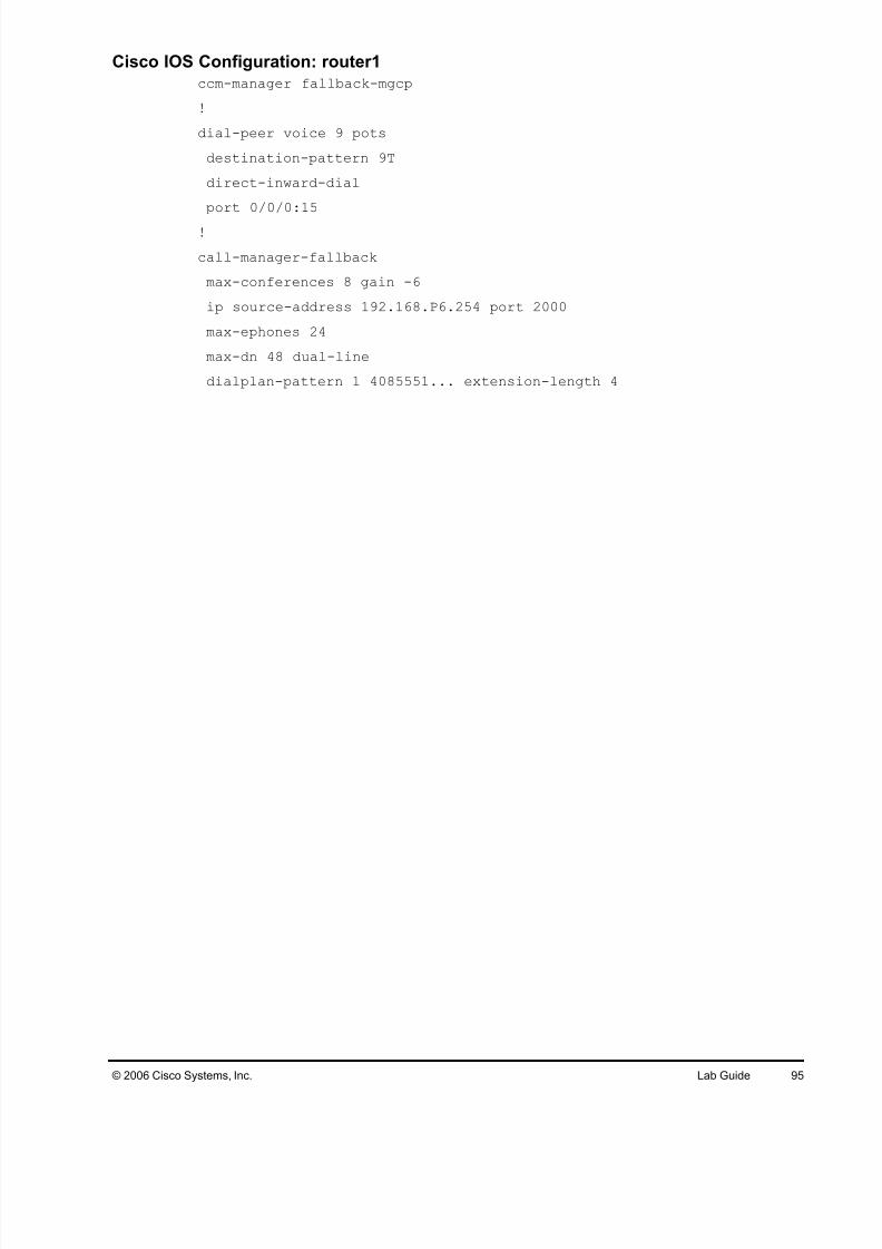
In this activity, you will configure SRST gateways for the San Jose MGCP gateway router1.
After completing this activity, you will be able to meet these objectives: Configure an SRST reference point in Cisco Unified CallManager and assign it to a device
pool
Configure Cisco Unified CallManager fallback on the Cisco IOS gateway to allow phones
to register
Configure MGCP-to-H.323 fallback to allow PSTN calls during a fallback operation
Visual Objective
The figure illustrates what you will accomplish in this activity.
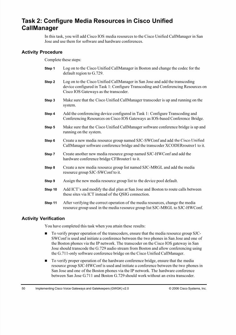
Task 2: Configure Media Resources in Cisco UnifiedCallManager
In this task, you will add Cisco IOS media resources to the Cisco Unified CallManager in San
Jose and use them for software and hardware conferences.
Activity Procedure
Complete these steps:
Step 1 Log on to the Cisco Unified CallManager in Boston and change the codec for the
default region to G.729.
Step 2 Log on to the Cisco Unified CallManager in San Jose and add the transcoding
device configured in Task 1: Configure Transcoding and Conferencing Resources on
Cisco IOS Gateways as the transcoder.
Step 3 Make sure that the Cisco Unified CallManager transcoder is up and running on the
system.
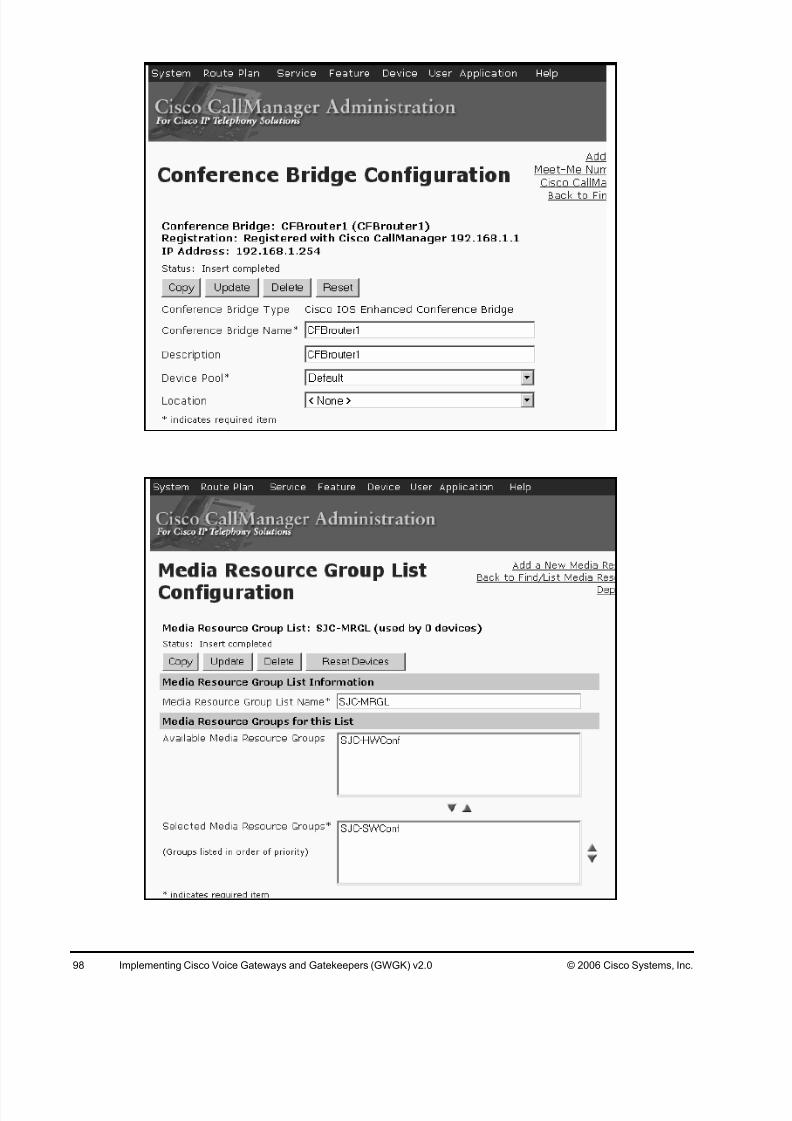
Step 4 Add the conferencing device configured in Task 1: Configure Transcoding and
Conferencing Resources on Cisco IOS Gateways as IOS-based Conference Bridge.
Step 5 Make sure that the Cisco Unified CallManager software conference bridge is up and
running on the system.
Step 6 Create a new media resource group named SJC-SWConf and add the Cisco Unified
CallManager software conference bridge and the transcoder XCODERroutrer1 to it.
Step 7 Create another new media resource group named SJC-HWConf and add the
hardware conference bridge CFBrouter1 to it.
Step 8 Create a new media resource group list named SJC-MRGL and add the media
resource group SJC-SWConf to it.
Step 9 Assign the new media resource group list to the device pool default.
Step 10 Add ICT’s and modify the dial plan at San Jose and Boston to route calls between
these sites via ICT instead of the QSIG connection.
Step 11 After verifying the correct operation of the media resources, change the media
resource group used in the media resource group list SJC-MRGL to SJC-HWConf.
Activity Verification
You have completed this task when you attain these results:
To verify proper operation of the transcoders, ensure that the media resource group SJC-SWConf is used and initiate a conference between the two phones in San Jose and one of
the Boston phones via the IP network. The transcoder on the Cisco IOS gateway in San
Jose should transcode the G.729 audio stream from Boston and allow conferencing using
the G.711-only software conference bridge on the Cisco Unified CallManager.
To verify proper operation of the hardware conference bridge, ensure that the media
resource group SJC-HWConf is used and initiate a conference between the two phones in
San Jose and one of the Boston phones via the IP network. The hardware conference
between San Jose G.711 and Boston G.729 should work without an extra transcoder.
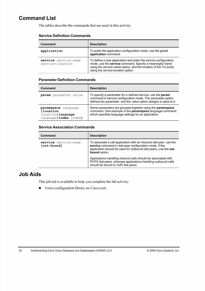
The tables describe the commands that are used in this activity.
Service Definition Commands
Command Description
application To enter the application configuration mode, use the globalapplication command.
service service-nameservice-location
To define a new application and enter the service configurationmode, use the service command. Specify a meaningful nameusing the service-name option, and the location of the Tcl scriptusing the service-location option.
Parameter Definition Commands
Command Description
param parameter value To specify a parameter for a defined service, use the param command in service configuration mode. The parameter option
defines the parameter. and the value option assigns a value to it.
paramspace language {locationlocation|languagelanguage|index index }
Some parameters are grouped together using the paramspace command. One example is the paramspace language command,which specifies language settings for an application.
Service Association Commands
Command Description
service service-name[out-bound]
To associate a call application with an inbound dial peer, use theservice command in dial-peer configuration mode. If theapplication should be used for outbound dial peers, use the out-
bound option.
Applications handling inbound calls should be associated withPOTS dial peers, whereas applications handling outbound callsshould be bound to VoIP dial peers.
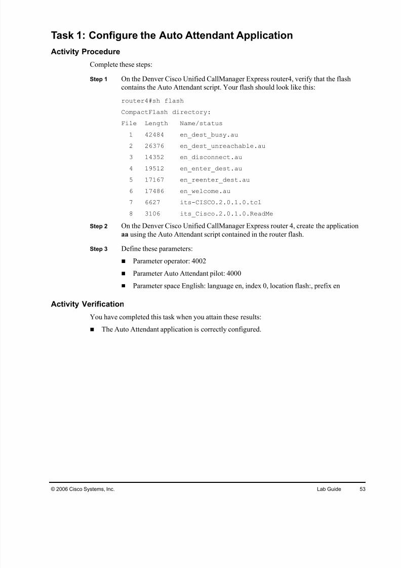
Job Aids
This job aid is available to help you complete the lab activity:
These are the resources and equipment that are required to complete this activity:
San Jose Cisco Unified CallManager cluster
Chicago Cisco Unified CallManager Express router3
San Jose gatekeeper GK
San Jose IP phones
Chicago IP phones
Command List
The tables describe the commands that are used in this activity.
Gatekeeper Configuration Commands
Command Description
gatekeeperTo enter gatekeeper configuration mode, use thegatekeeper command in global configuration mode.
zone local zone-namedomain-name [ras-IP-address]
Specifies a zone controlled by a gatekeeper with thesearguments:
gatekeeper-name: Specifies the gatekeeper name or zone name. This is usually the fully domain-qualifiedhost name of the gatekeeper. For example, if thedomain name is cisco.com, the gatekeeper namemight be gk1.cisco.com. However, if the gatekeeper iscontrolling multiple zones, the gatekeeper name for each zone should be some unique string that has amnemonic value.
domain-name: Specifies the domain name served by
this gatekeeper. ras-IP-address: (Optional) Specifies the IP address of
one of the interfaces on the gatekeeper. When thegatekeeper responds to gatekeeper discoverymessages, it signals the endpoint or gateway to usethis address in future communications.
Note: Setting this address for one local zone makes it theaddress used for all local zones.
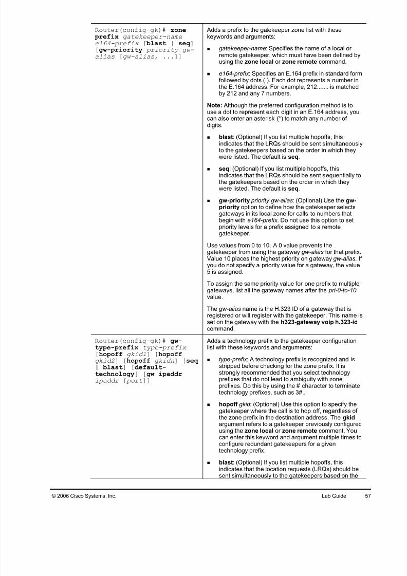
Adds a prefix to the gatekeeper zone list with thesekeywords and arguments:
gatekeeper-name: Specifies the name of a local or remote gatekeeper, which must have been defined byusing the zone local or zone remote command.
e164-prefix : Specifies an E.164 prefix in standard formfollowed by dots (.). Each dot represents a number inthe E.164 address. For example, 212....... is matchedby 212 and any 7 numbers.
Note: Although the preferred configuration method is touse a dot to represent each digit in an E.164 address, youcan also enter an asterisk (*) to match any number of digits.
blast: (Optional) If you list multiple hopoffs, thisindicates that the LRQs should be sent simultaneouslyto the gatekeepers based on the order in which theywere listed. The default is seq.
seq: (Optional) If you list multiple hopoffs, thisindicates that the LRQs should be sent sequentially tothe gatekeepers based on the order in which theywere listed. The default is seq.
gw-priority priority gw-alias: (Optional) Use the gw-priority option to define how the gatekeeper selectsgateways in its local zone for calls to numbers thatbegin with e164-prefix . Do not use this option to setpriority levels for a prefix assigned to a remotegatekeeper.
Use values from 0 to 10. A 0 value prevents thegatekeeper from using the gateway gw-alias for that prefix.Value 10 places the highest priority on gateway gw-alias. If you do not specify a priority value for a gateway, the value5 is assigned.
To assign the same priority value for one prefix to multiplegateways, list all the gateway names after the pri-0-to-10 value.
The gw-alias name is the H.323 ID of a gateway that isregistered or will register with the gatekeeper. This name isset on the gateway with the h323-gateway voip h.323-idcommand.
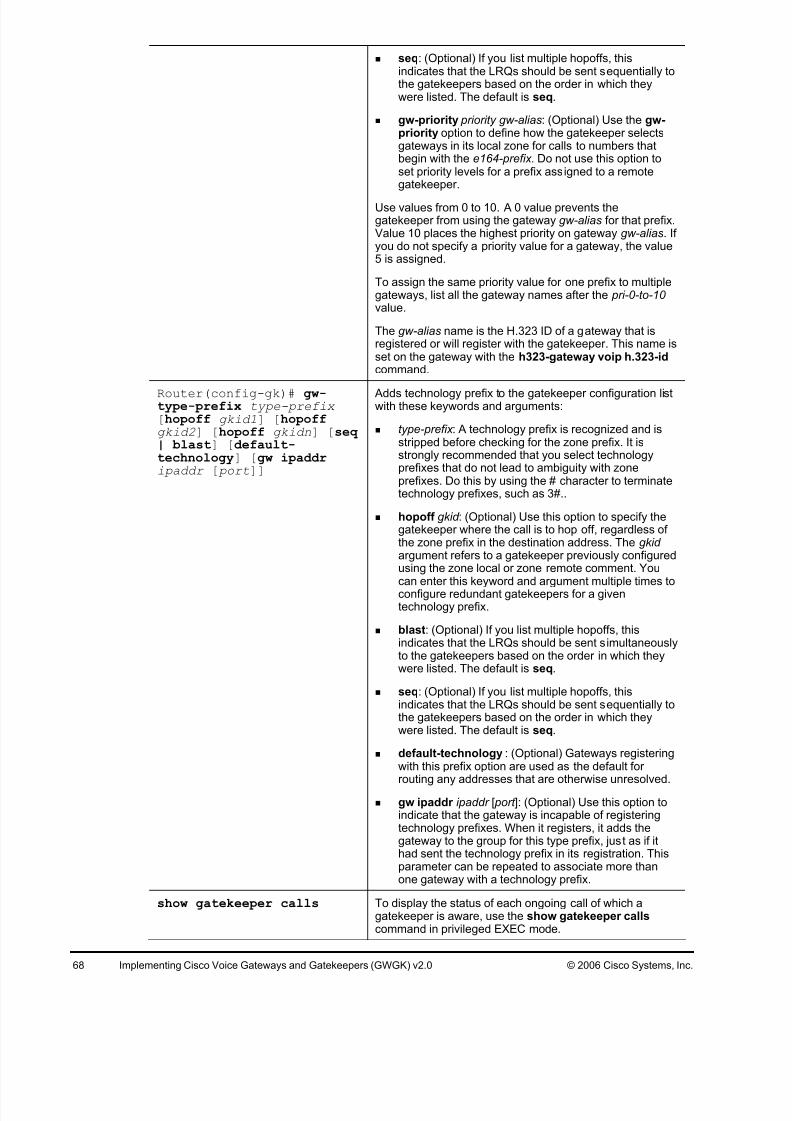
Adds a technology prefix to the gatekeeper configurationlist with these keywords and arguments:
type-prefix : A technology prefix is recognized and isstripped before checking for the zone prefix. It isstrongly recommended that you select technologyprefixes that do not lead to ambiguity with zoneprefixes. Do this by using the # character to terminatetechnology prefixes, such as 3#..
hopoff gkid : (Optional) Use this option to specify thegatekeeper where the call is to hop off, regardless of the zone prefix in the destination address. The gkid argument refers to a gatekeeper previously configuredusing the zone local or zone remote comment. Youcan enter this keyword and argument multiple times toconfigure redundant gatekeepers for a giventechnology prefix.
blast: (Optional) If you list multiple hopoffs, thisindicates that the location requests (LRQs) should besent simultaneously to the gatekeepers based on the
order in which they were listed. The default is seq.
seq: (Optional) If you list multiple hopoffs, thisindicates that the LRQs should be sent sequentially tothe gatekeepers based on the order in which theywere listed. The default is seq.
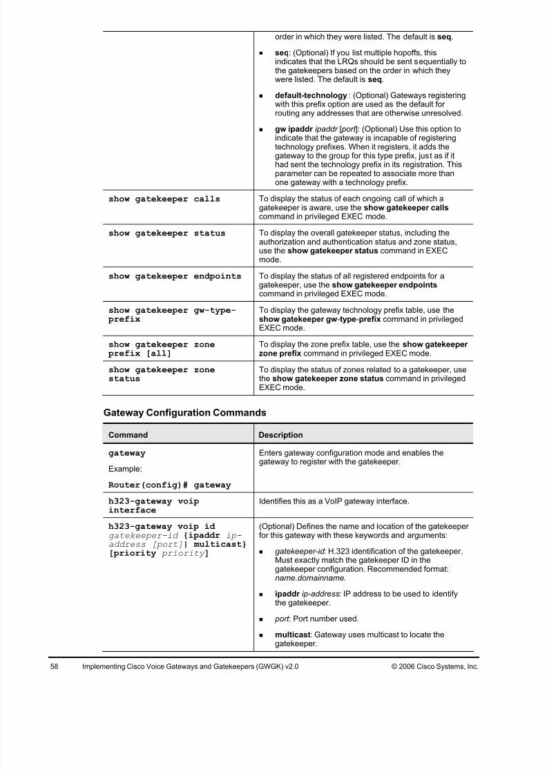
default-technology : (Optional) Gateways registeringwith this prefix option are used as the default for routing any addresses that are otherwise unresolved.
gw ipaddr ipaddr [ port ]: (Optional) Use this option to
indicate that the gateway is incapable of registeringtechnology prefixes. When it registers, it adds thegateway to the group for this type prefix, just as if ithad sent the technology prefix in its registration. Thisparameter can be repeated to associate more thanone gateway with a technology prefix.
show gatekeeper calls To display the status of each ongoing call of which agatekeeper is aware, use the show gatekeeper callscommand in privileged EXEC mode.
show gatekeeper status To display the overall gatekeeper status, including theauthorization and authentication status and zone status,use the show gatekeeper status command in EXECmode.
show gatekeeper endpoints To display the status of all registered endpoints for agatekeeper, use the show gatekeeper endpoints command in privileged EXEC mode.
show gatekeeper gw-type- prefix
To display the gateway technology prefix table, use theshow gatekeeper gw-type-prefix command in privilegedEXEC mode.
show gatekeeper zone prefix [all]
To display the zone prefix table, use the show gatekeeper zone prefix command in privileged EXEC mode.
show gatekeeper zonestatus
To display the status of zones related to a gatekeeper, usethe show gatekeeper zone status command in privilegedEXEC mode.
Gateway Configuration Commands
Command Description
gateway
Example:
Router(config)# gateway
Enters gateway configuration mode and enables thegateway to register with the gatekeeper.
h323-gateway voipinterface
Identifies this as a VoIP gateway interface.
h323-gateway voip id gatekeeper-id {ipaddr ip-
address [port]| multicast}[priority priority ]
(Optional) Defines the name and location of the gatekeeper for this gateway with these keywords and arguments:
gatekeeper-id : H.323 identification of the gatekeeper.Must exactly match the gatekeeper ID in thegatekeeper configuration. Recommended format:name.domainname.
ipaddr ip-address: IP address to be used to identifythe gatekeeper.
port : Port number used.
multicast: Gateway uses multicast to locate thegatekeeper.
priority priority : Priority of this gatekeeper. Theacceptable range is 1 to 127, and the default is 127.
h323-gateway voip h323-id interface-id
(Optional) Defines the H.323 name of the gateway,identifying this gateway to its associated gatekeeper.
Usually this ID is the name of the gateway, with thegatekeeper domain name appended to the end like this:name@domainname.
h323-gateway voip tech-
prefix prefix
(Optional) Defines the numbers used as the technology
prefix that the gateway registers with the gatekeeper.
This command can contain up to 11 characters. Although itis not strictly necessary, a pound symbol (#) is frequentlyused as the last digit in a prefix. Valid characters are 0 to 9,#, and *.
session target ras RAS signaling function protocol is being used, meaningthat a gatekeeper is consulted to translate the E.164address into an IP address.
Job Aids
There are no job aids for this activity.
Task 1: Configure Local Zones at the San Jose Gatekeeper
Configure two local zones, SanJose and Chicago, on the San Jose site gatekeeper. Configure
appropriate dial-plan information for the gatekeeper to resolve calls between sites SanJose and
Chicago.
Activity Procedure
Complete these steps:
Step 1 On the San Jose gatekeeper GK, configure a gatekeeper using these parameters:
Local zone SJC, domain cisco.com, IP address of the LAN interface Local zone CHI, domain cisco.com, IP address of the LAN interface
Step 2 Enable the gatekeeper process on GK.
Activity Verification
You have completed this task when you attain these results:
The GK gatekeeper is up and running with two local zones: SanJose and Chicago.
The tables describe the commands that are used in this activity.
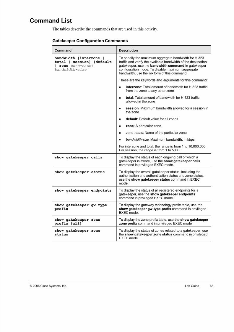
Gatekeeper Configuration Commands
Command Description
bandwidth {interzone |total | session} {default| zone zone-name}bandwidth-size
To specify the maximum aggregate bandwidth for H.323traffic and verify the available bandwidth of the destinationgatekeeper, use the bandwidth command in gatekeeper configuration mode. To disable maximum aggregatebandwidth, use the no form of this command.
These are the keywords and arguments for this command:
interzone: Total amount of bandwidth for H.323 trafficfrom the zone to any other zone
total: Total amount of bandwidth for H.323 trafficallowed in the zone
session: Maximum bandwidth allowed for a session inthe zone
default: Default value for all zones
zone: A particular zone
zone-name: Name of the particular zone
bandwidth-size: Maximum bandwidth, in kbps
For interzone and total, the range is from 1 to 10,000,000.For session, the range is from 1 to 5000.
show gatekeeper calls To display the status of each ongoing call of which agatekeeper is aware, use the show gatekeeper callscommand in privileged EXEC mode.
show gatekeeper status To display the overall gatekeeper status, including the
authorization and authentication status and zone status,use the show gatekeeper status command in EXECmode.
show gatekeeper endpoints To display the status of all registered endpoints for agatekeeper, use the show gatekeeper endpoints command in privileged EXEC mode.
show gatekeeper gw-type- prefix
To display the gateway technology prefix table, use theshow gatekeeper gw-type-prefix command in privilegedEXEC mode.
show gatekeeper zone prefix [all]
To display the zone prefix table, use the show gatekeeper zone prefix command in privileged EXEC mode.
show gatekeeper zonestatusTo display the status of zones related to a gatekeeper, usethe show gatekeeper zone status command in privilegedEXEC mode.
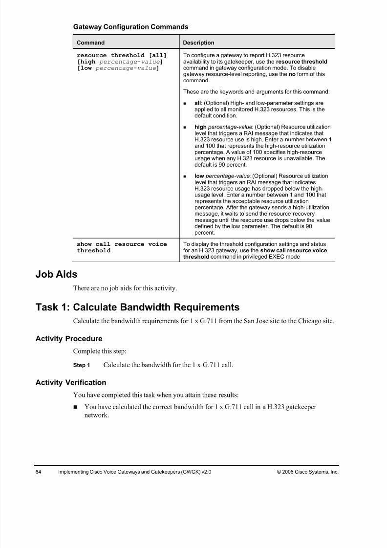
To configure a gateway to report H.323 resourceavailability to its gatekeeper, use the resource thresholdcommand in gateway configuration mode. To disablegateway resource-level reporting, use the no form of thiscommand.
These are the keywords and arguments for this command:
all: (Optional) High- and low-parameter settings areapplied to all monitored H.323 resources. This is thedefault condition.
high percentage-value: (Optional) Resource utilizationlevel that triggers a RAI message that indicates thatH.323 resource use is high. Enter a number between 1and 100 that represents the high-resource utilizationpercentage. A value of 100 specifies high-resourceusage when any H.323 resource is unavailable. Thedefault is 90 percent.
low percentage-value: (Optional) Resource utilizationlevel that triggers an RAI message that indicatesH.323 resource usage has dropped below the high-usage level. Enter a number between 1 and 100 thatrepresents the acceptable resource utilizationpercentage. After the gateway sends a high-utilizationmessage, it waits to send the resource recoverymessage until the resource use drops below the valuedefined by the low parameter. The default is 90percent.
show call resource voicethreshold
To display the threshold configuration settings and statusfor an H.323 gateway, use the show call resource voicethreshold command in privileged EXEC mode
Job Aids
There are no job aids for this activity.
Task 1: Calculate Bandwidth Requirements
Calculate the bandwidth requirements for 1 x G.711 from the San Jose site to the Chicago site.
Activity Procedure
Complete this step:
Step 1 Calculate the bandwidth for the 1 x G.711 call.
Activity VerificationYou have completed this task when you attain these results:
You have calculated the correct bandwidth for 1 x G.711 call in a H.323 gatekeeper
Lab 5-3: Configuring Remote ZonesComplete this lab activity to practice what you learned in the related module.
Activity Objective
In this activity, you will configure the Boston H.323 gateway router2 to also provide
gatekeeper functionality for Boston. The Boston Cisco Unified CallManager cluster willregister with the gatekeeper in Boston. Calls will then be routed between the two gatekeepers.
After completing this activity, you will be able to meet these objectives:
Configure remote zones on the gatekeeper
Configure remote zone prefixes that point to another gatekeeper in the network
Visual Objective
The figure illustrates what you will accomplish in this activity.
The tables describe the commands that are used in this activity.
Gatekeeper Configuration Commands
Command Description
gatekeeper To enter gatekeeper configuration mode, use the
gatekeeper command in global configuration mode.
zone local zone-namedomain-name [ras-IP-address]
Specifies a zone controlled by a gatekeeper with thesearguments:
gatekeeper-name: Specifies the gatekeeper name or zone name. This is usually the fully domain-qualifiedhost name of the gatekeeper. For example, if thedomain name is cisco.com, the gatekeeper namemight be gk1.cisco.com. However, if the gatekeeper iscontrolling multiple zones, the gatekeeper name for each zone should be some unique string that has amnemonic value.
domain-name: Specifies the domain name served bythis gatekeeper.
ras-IP-address: (Optional) Specifies the IP address of one of the interfaces on the gatekeeper. When thegatekeeper responds to gatekeeper discoverymessages, it signals the endpoint or gateway to usethis address in future communications.
Note: Setting this address for one local zone makes it theaddress used for all local zones.
Use the zone remote command in gatekeeper configuration mode to statically specify a remote zone if DNS is unavailable or undesirable. Use the no form of thiscommand to remove the remote zone.
Adds a prefix to the gatekeeper zone list with thesekeywords and arguments:
gatekeeper-name: Specifies the name of a local or remote gatekeeper, which must have been defined byusing the zone local or zone remote command.
e164-prefix : Specifies an E.164 prefix in standard formfollowed by dots (.). Each dot represents a number inthe E.164 address. For example, 212....... is matchedby 212 and any 7 numbers.
Note: Although the preferred configuration method is touse a dot to represent each digit in an E.164 address, youcan also enter an asterisk (*) to match any number of digits.
blast: (Optional) If you list multiple hopoffs, thisindicates that the LRQs should be sent simultaneouslyto the gatekeepers based on the order in which theywere listed. The default is seq.
seq: (Optional) If you list multiple hopoffs, thisindicates that the LRQs should be sent sequentially tothe gatekeepers based on the order in which theywere listed. The default is seq.
gw-priority priority gw-alias: (Optional) Use the gw-priority option to define how the gatekeeper selectsgateways in its local zone for calls to numbers thatbegin with the e164-prefix. Do not use this option toset priority levels for a prefix assigned to a remotegatekeeper.
Use values from 0 to 10. A 0 value prevents thegatekeeper from using the gateway gw-alias for that prefix.Value 10 places the highest priority on gateway gw-alias. If you do not specify a priority value for a gateway, the value5 is assigned.
To assign the same priority value for one prefix to multiplegateways, list all the gateway names after the pri-0-to-10 value.
The gw-alias name is the H.323 ID of a gateway that isregistered or will register with the gatekeeper. This name isset on the gateway with the h323-gateway voip h.323-idcommand.
Adds technology prefix to the gatekeeper configuration listwith these keywords and arguments:
type-prefix : A technology prefix is recognized and isstripped before checking for the zone prefix. It isstrongly recommended that you select technologyprefixes that do not lead to ambiguity with zoneprefixes. Do this by using the # character to terminatetechnology prefixes, such as 3#..
hopoff gkid : (Optional) Use this option to specify thegatekeeper where the call is to hop off, regardless of the zone prefix in the destination address. The gkid argument refers to a gatekeeper previously configuredusing the zone local or zone remote comment. Youcan enter this keyword and argument multiple times toconfigure redundant gatekeepers for a giventechnology prefix.
blast: (Optional) If you list multiple hopoffs, thisindicates that the LRQs should be sent simultaneouslyto the gatekeepers based on the order in which theywere listed. The default is seq.
seq: (Optional) If you list multiple hopoffs, thisindicates that the LRQs should be sent sequentially tothe gatekeepers based on the order in which theywere listed. The default is seq.
default-technology : (Optional) Gateways registeringwith this prefix option are used as the default for routing any addresses that are otherwise unresolved.
gw ipaddr ipaddr [ port ]: (Optional) Use this option toindicate that the gateway is incapable of registeringtechnology prefixes. When it registers, it adds thegateway to the group for this type prefix, just as if ithad sent the technology prefix in its registration. Thisparameter can be repeated to associate more thanone gateway with a technology prefix.
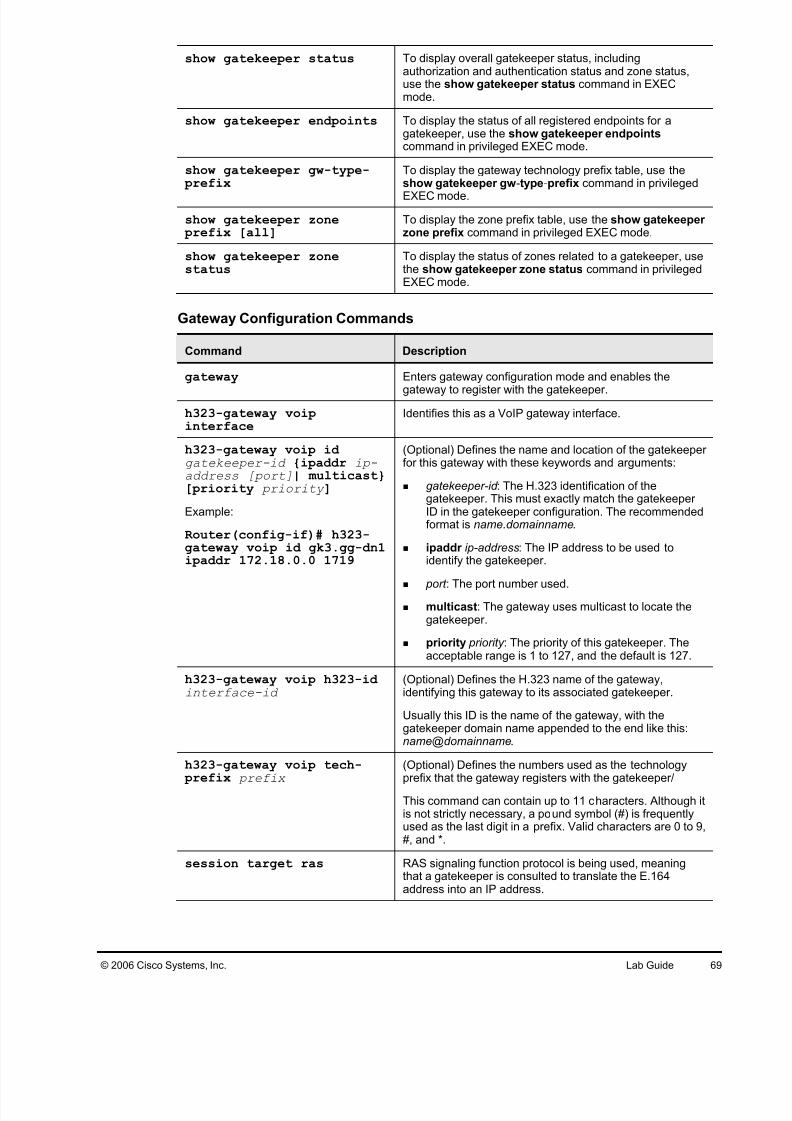
show gatekeeper calls To display the status of each ongoing call of which agatekeeper is aware, use the show gatekeeper callscommand in privileged EXEC mode.
show gatekeeper status To display overall gatekeeper status, includingauthorization and authentication status and zone status,use the show gatekeeper status command in EXECmode.
show gatekeeper endpoints To display the status of all registered endpoints for agatekeeper, use the show gatekeeper endpoints command in privileged EXEC mode.
show gatekeeper gw-type- prefix
To display the gateway technology prefix table, use theshow gatekeeper gw-type-prefix command in privileged
EXEC mode.
show gatekeeper zone prefix [all]
To display the zone prefix table, use the show gatekeeper zone prefix command in privileged EXEC mode.
show gatekeeper zonestatus
To display the status of zones related to a gatekeeper, usethe show gatekeeper zone status command in privilegedEXEC mode.
Gateway Configuration Commands
Command Description
gateway Enters gateway configuration mode and enables the
gateway to register with the gatekeeper.
h323-gateway voipinterface
Identifies this as a VoIP gateway interface.
h323-gateway voip id gatekeeper-id {ipaddr ip-address [port]| multicast}[priority priority ]
Example:
Router(config-if)# h323-gateway voip id gk3.gg-dn1ipaddr 172.18.0.0 1719
(Optional) Defines the name and location of the gatekeeper for this gateway with these keywords and arguments:
gatekeeper-id : The H.323 identification of thegatekeeper. This must exactly match the gatekeeper ID in the gatekeeper configuration. The recommendedformat is name.domainname.
ipaddr ip-address: The IP address to be used toidentify the gatekeeper.
port : The port number used. multicast: The gateway uses multicast to locate the
gatekeeper.
priority priority : The priority of this gatekeeper. Theacceptable range is 1 to 127, and the default is 127.
h323-gateway voip h323-id interface-id
(Optional) Defines the H.323 name of the gateway,identifying this gateway to its associated gatekeeper.
Usually this ID is the name of the gateway, with thegatekeeper domain name appended to the end like this:name@domainname.
h323-gateway voip tech- prefix prefix
(Optional) Defines the numbers used as the technologyprefix that the gateway registers with the gatekeeper/
This command can contain up to 11 characters. Although itis not strictly necessary, a pound symbol (#) is frequentlyused as the last digit in a prefix. Valid characters are 0 to 9,#, and *.
session target ras RAS signaling function protocol is being used, meaningthat a gatekeeper is consulted to translate the E.164address into an IP address.
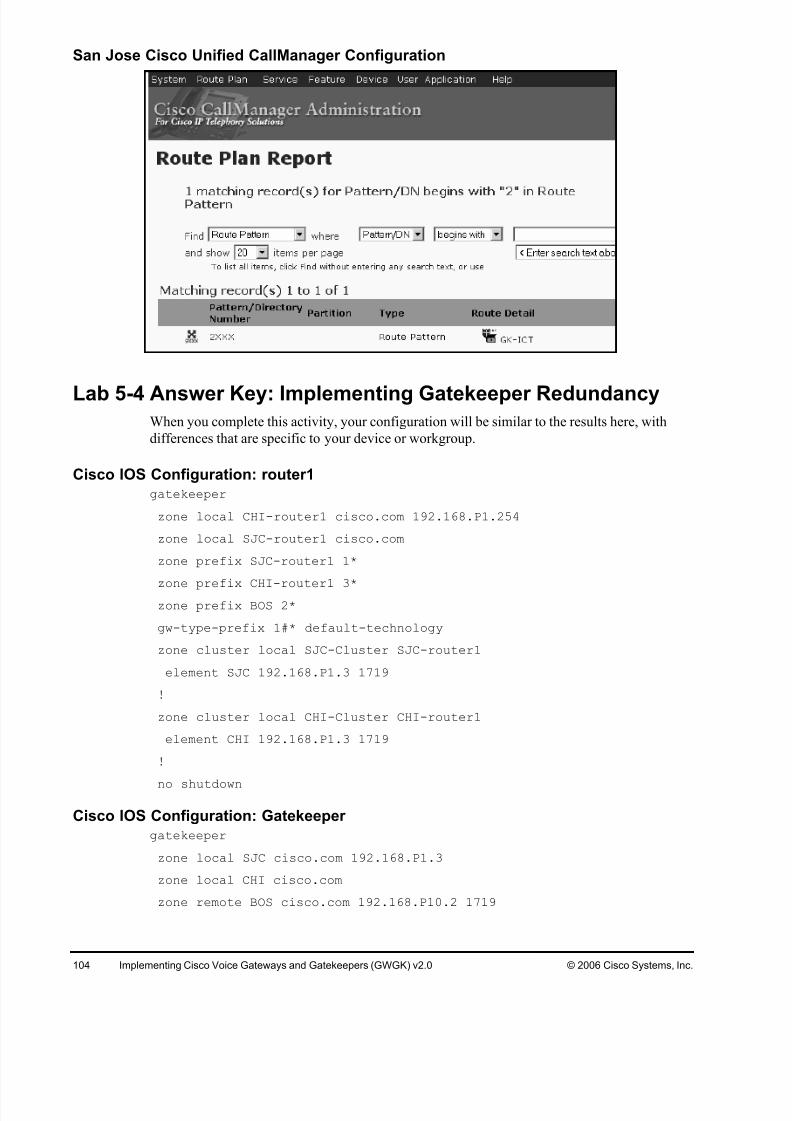
Lab 5-4: Implementing Gatekeeper RedundancyComplete this lab activity to practice what you learned in the related module.
Activity Objective
In this activity, you will configure a redundant GUP cluster in San Jose. The cluster will use the
already-configured San Jose gatekeeper GK and another gatekeeper configured on the San JoseMGCP gateway router1. After completing this activity, you will be able to meet this objective:
Configure a GUP cluster and verify correct operation
Required Resources
These are the resources and equipment that are required to complete this activity:
The tables describe the commands that are used in this activity.
Gatekeeper Configuration Commands
Command Description
gatekeeper To enter gatekeeper configuration mode, use the gatekeeper command in global configuration mode.
zone local zone-namedomain-name [ras-IP-address]
Specifies a zone controlled by a gatekeeper with thesearguments:
gatekeeper-name: Specifies the gatekeeper name or zonename. This is usually the fully domain-qualified host nameof the gatekeeper. For example, if the domain name iscisco.com, the gatekeeper name might be gk1.cisco.com.However, if the gatekeeper is controlling multiple zones,the gatekeeper name for each zone should be someunique string that has a mnemonic value.
domain-name: Specifies the domain name served by thisgatekeeper.
ras-IP-address: (Optional) Specifies the IP address of oneof the interfaces on the gatekeeper. When the gatekeeper responds to gatekeeper discovery messages, it signalsthe endpoint or gateway to use this address in futurecommunications.
Note: Setting this address for one local zone makes it theaddress used for all local zones.
Adds a prefix to the gatekeeper zone list with these keywordsand arguments:
gatekeeper-name: Specifies the name of a local or remote
gatekeeper, which must have been defined by using thezone local or zone remote command.
e164-prefix : Specifies an E.164 prefix in standard formfollowed by dots (.). Each dot represents a number in theE.164 address. For example, 212....... is matched by 212and any 7 numbers.
Note: Although the preferred configuration method is to use adot to represent each digit in an E.164 address, you can alsoenter an asterisk (*) to match any number of digits.
blast: (Optional) If you list multiple hopoffs, this indicatesthat the LRQs should be sent simultaneously to thegatekeepers based on the order in which they were listed.The default is seq.
seq: (Optional) If you list multiple hopoffs, this indicatesthat the LRQs should be sent sequentially to thegatekeepers based on the order in which they were listed.The default is seq.
gw-priority priority gw-alias: (Optional) Use the gw-priority option to define how the gatekeeper selectsgateways in its local zone for calls to numbers that beginwith e164-prefix . Do not use this option to set prioritylevels for a prefix assigned to a remote gatekeeper.
Use values from 0 to 10. A 0 value prevents the gatekeeper
from using the gateway gw-alias for that prefix. Value 10places the highest priority on gateway gw-alias. If you do notspecify a priority value for a gateway, the value 5 is assigned.
To assign the same priority value for one prefix to multiplegateways, list all the gateway names after the pri-0-to-10 value.
The gw-alias name is the H.323 ID of a gateway that isregistered or will register with the gatekeeper. This name is seton the gateway with the h323-gateway voip h.323-idcommand.
Adds technology prefix to the gatekeeper configuration list withthese keywords and arguments:
type-prefix : A technology prefix is recognized and isstripped before checking for the zone prefix. It is stronglyrecommended that you select technology prefixes that donot lead to ambiguity with zone prefixes. Do this by usingthe # character to terminate technology prefixes, such as3#..
hopoff gkid : (Optional) Use this option to specify thegatekeeper where the call is to hop off, regardless of thezone prefix in the destination address. The gkid argumentrefers to a gatekeeper previously configured using the
zone local or zone remote comment. You can enter thiskeyword and argument multiple times to configureredundant gatekeepers for a given technology prefix.
blast: (Optional) If you list multiple hopoffs, this indicatesthat the LRQs should be sent simultaneously to thegatekeepers based on the order in which they were listed.The default is seq.
seq: (Optional) If you list multiple hopoffs, this indicatesthat the LRQs should be sent sequentially to thegatekeepers based on the order in which they were listed.The default is seq.
default-technology : (Optional) Gateways registeringwith this prefix option are used as the default for routing
any addresses that are otherwise unresolved.
gw ipaddr ipaddr [ port ]: (Optional) Use this option toindicate that the gateway is incapable of registeringtechnology prefixes. When it registers, it adds thegateway to the group for this type prefix, just as if it hadsent the technology prefix in its registration. Thisparameter can be repeated to associate more than onegateway with a technology prefix.
zone cluster local cluster -name local-zone-name
Use the zone cluster local command in gatekeeper configuration mode to define a local grouping of gatekeepers,including the gatekeeper that you are configuring. Use the no form of this command to disable the local grouping of gatekeepers.
element gatekeeper -nameip-address [ port]
Use the element command in gatekeeper configuration modeto define component elements of local or remote clusters. Usethe no form of this command to disable component elementsof local or remote clusters.
show gatekeeper calls To display the status of each ongoing call of which agatekeeper is aware, use the show gatekeeper callscommand in privileged EXEC mode.
show gatekeeper status To display the overall gatekeeper status, including theauthorization and authentication status and the zone status,use the show gatekeeper status command in EXEC mode.
To display the status of all registered endpoints for agatekeeper, use the show gatekeeper endpoints commandin privileged EXEC mode.
show gatekeeper gw-type- prefix
To display the gateway technology prefix table, use the showgatekeeper gw-type-prefix command in privileged EXECmode.
show gatekeeper zone prefix [all]
To display the zone prefix table, use the show gatekeeper zone prefix command in privileged EXEC mode.
show gatekeeper zonestatus To display the status of zones related to a gatekeeper, use theshow gatekeeper zone status command in privileged EXECmode.
Gateway Configuration Commands
Command Description
gateway
Example:
Router(config)# gateway
Enters gateway configuration mode and enables thegateway to register with the gatekeeper.
h323-gateway voipinterface
Identifies this as a VoIP gateway interface.
h323-gateway voip id gatekeeper-id {ipaddr ip-address [port]| multicast}[priority priority ]
(Optional) Defines the name and location of the gatekeeper for this gateway with these keywords and arguments.
gatekeeper-id : The H.323 identification of thegatekeeper. This must exactly match the gatekeeper ID in the gatekeeper configuration. The recommendedformat is name.domainname.
ipaddr ip-address: The IP address to be used toidentify the gatekeeper.
port : The port number used.
multicast: The gateway uses multicast to locate the
gatekeeper.
priority priority : The priority of this gatekeeper. Theacceptable range is 1 to 127, and the default is 127.
h323-gateway voip h323-id interface-id
(Optional) Defines the H.323 name of the gateway,identifying this gateway to its associated gatekeeper.
Usually this ID is the name of the gateway, with thegatekeeper domain name appended to the end like this:name@domainname.
h323-gateway voip tech- prefix prefix
(Optional) Defines the numbers used as the technologyprefix that the gateway registers with the gatekeeper.
This command can contain up to 11 characters. Although it
is not strictly necessary, a pound symbol (#) is frequentlyused as the last digit in a prefix. Valid characters are 0 to 9,#, and *.
session target ras RAS signaling function protocol is being used, meaningthat a gatekeeper is consulted to translate the E.164address into an IP address.
The table describes the commands that are used in this activity.
IPIPGW Configuration Commands
Command Description
allow-connections from-type to to-type
Enables protocol Interworking on an IP-to-IP gateway.
media [flow-around | flow-through]
Configures how media streams are handled on an IP-to-IPgateway in dial-peer, voice-class, or voice-serviceconfiguration mode.
codec transparent Enables codec capabilities to be passed transparentlybetween endpoints on an IP-to-IP gateway. This can alsobe configured in a voice class.
Job Aids
There are no job aids for this activity.
Task 1: Configure an IP-to-IP Gateway for ProtocolInterworking and Address Hiding
In this task, you will configure the San Jose MGCP gateway router1 to also act as an IP-to-IP
gateway. Calls to an SIP carrier will travel through the IP-to-IP gateway, with the internal call
leg being H.323.
Activity Procedure
Complete these steps:
Step 1 On the San Jose MGCP gateway router1, shut down the gatekeeper process.
Step 2 On the San Jose MGCP gateway router1, enable interworking between H.323 and
SIP.
Step 3 Ensure that the LAN interface is used for H.323 signaling.
Step 4 Create a new outbound SIP VoIP dial peer that will route calls to the SIP carrier.
192.168.10.254. The destination pattern should be a 9011T, G.711 mu-law codec.
Step 5 Create a new inbound H.323 VoIP dial peer that will accept calls from the San Jose
Cisco Unified CallManager cluster. Use a G.711 mu-law codec and an appropriate
incoming called number to ensure this dial peer is matched for inbound calls.
Step 6 Create a new sip-out voice translation profile that will strip off the leading 9011
used for international calls. Bind the profile to the VoIP dial peer pointing to the SIP
carrier for outbound calls.
Step 7 On the San Jose Cisco Unified CallManager cluster, add a new H.323 gateway that
will point to the San Jose IPIPGW gateway router1.
Step 8 Create a new route pattern 9011!# and specify the IP-to-IP gateway as the
Answer KeyThe correct answers and expected solutions for the activities that are described in this guide
appear here.
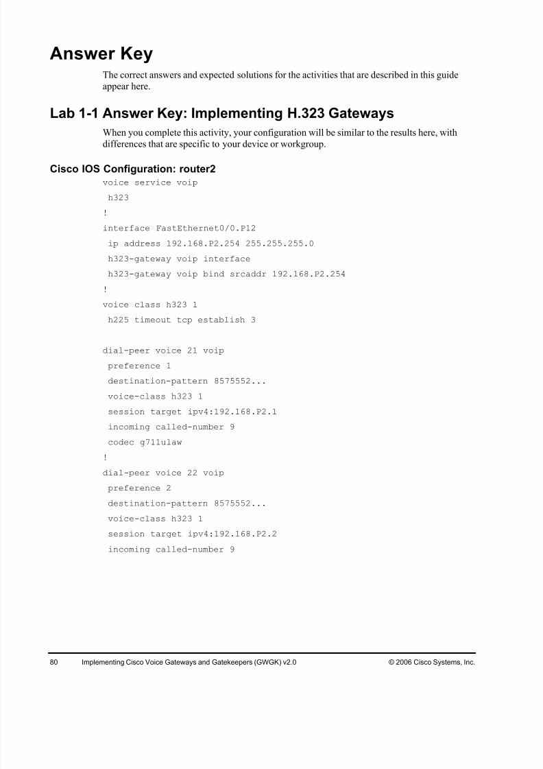
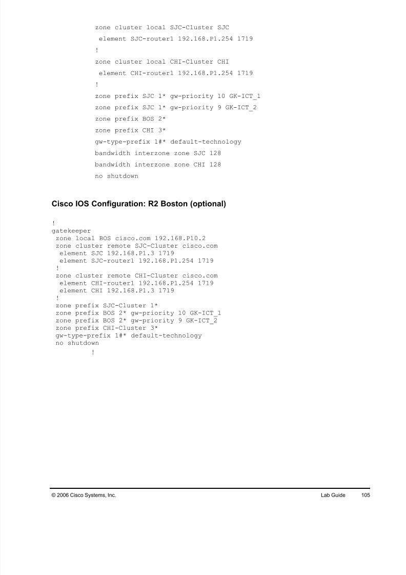
Lab 1-1 Answer Key: Implementing H.323 Gateways
When you complete this activity, your configuration will be similar to the results here, withdifferences that are specific to your device or workgroup.