8
H & HC Heat-Of-Compression Air Dryers
H & HC Heat-Of-Compression Air Dryers
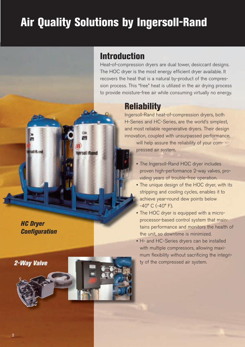
Air Quality Solutions by Ingersoll-Rand
2-Way Valve
2
IntroductionHeat-of-compression dryers are dual tower, desiccant designs.The HOC dryer is the most energy efficient dryer available. Itrecovers the heat that is a natural by-product of the compres-sion process. This “free” heat is utilized in the air drying processto provide moisture-free air while consuming virtually no energy.
ReliabilityIngersoll-Rand heat-of-compression dryers, both H-Series and HC-Series, are the world’s simplest,and most reliable regenerative dryers. Their designinnovation, coupled with unsurpassed performance,
will help assure the reliability of your com-pressed air system.
• The Ingersoll-Rand HOC dryer includesproven high-performance 2-way valves, pro-viding years of trouble-free operation.
• The unique design of the HOC dryer, with itsstripping and cooling cycles, enables it toachieve year-round dew points below-40° C (-40° F).
• The HOC dryer is equipped with a micro-processor-based control system that main-tains performance and monitors the health ofthe unit, so downtime is minimized.
• H- and HC-Series dryers can be installedwith multiple compressors, allowing maxi-mum flexibility without sacrificing the integri-ty of the compressed air system.
HC Dryer
Configuration
No other compressed air
dryer can deliver dry air at
so low an annual operating
cost 3
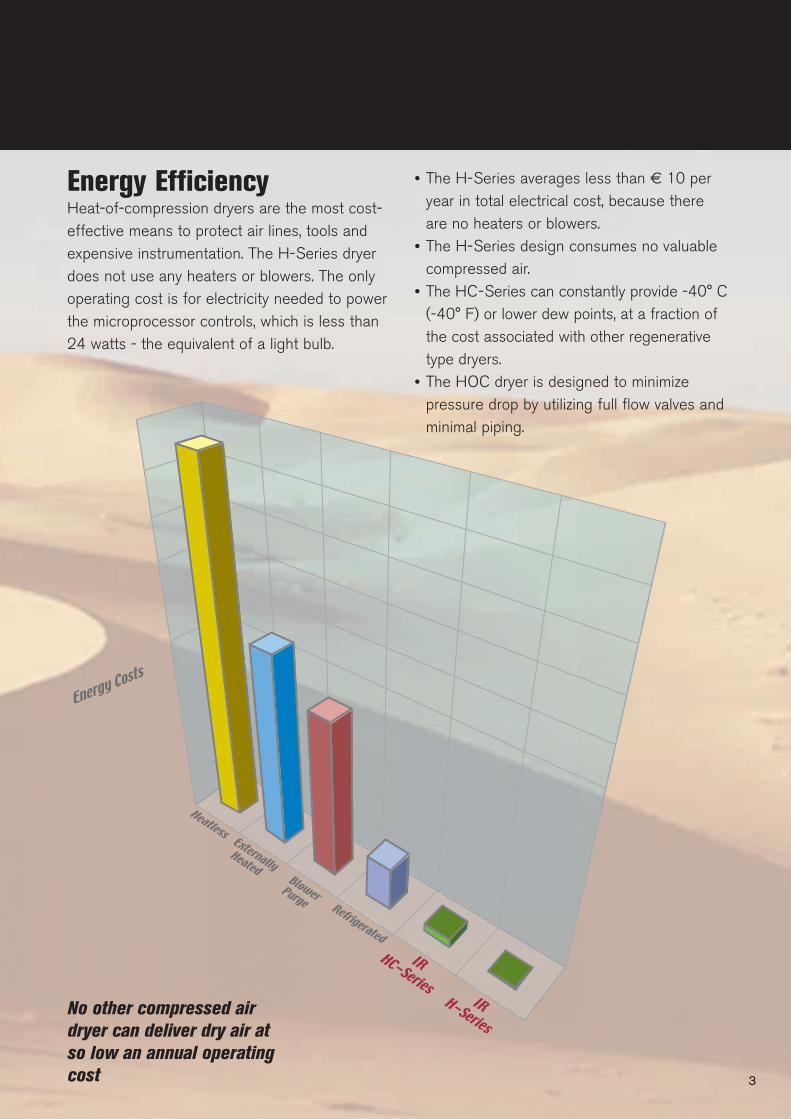
Energy EfficiencyHeat-of-compression dryers are the most cost-effective means to protect air lines, tools andexpensive instrumentation. The H-Series dryerdoes not use any heaters or blowers. The onlyoperating cost is for electricity needed to powerthe microprocessor controls, which is less than 24 watts - the equivalent of a light bulb.
• The H-Series averages less than € 10 peryear in total electrical cost, because thereare no heaters or blowers.
• The H-Series design consumes no valuablecompressed air.
• The HC-Series can constantly provide -40° C(-40° F) or lower dew points, at a fraction ofthe cost associated with other regenerativetype dryers.
• The HOC dryer is designed to minimizepressure drop by utilizing full flow valves andminimal piping.
Heat-Of-Compression Technology
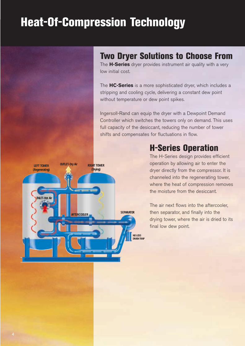
Two Dryer Solutions to Choose FromThe H-Series dryer provides instrument air quality with a verylow initial cost.
The HC-Series is a more sophisticated dryer, which includes astripping and cooling cycle, delivering a constant dew pointwithout temperature or dew point spikes.
Ingersoll-Rand can equip the dryer with a Dewpoint DemandController which switches the towers only on demand. This usesfull capacity of the desiccant, reducing the number of towershifts and compensates for fluctuations in flow.
H-Series OperationThe H-Series design provides efficientoperation by allowing air to enter thedryer directly from the compressor. It ischanneled into the regenerating tower,where the heat of compression removesthe moisture from the desiccant.
The air next flows into the aftercooler,then separator, and finally into thedrying tower, where the air is dried to itsfinal low dew point.
4
LEFT TOWER(Regenerating)
OUTLET-Dry Air RIGHT TOWER (Drying)
SEPARATOR
NO LOSSDRAIN TRAP
INLET-Hot Air
AFTERCOOLER
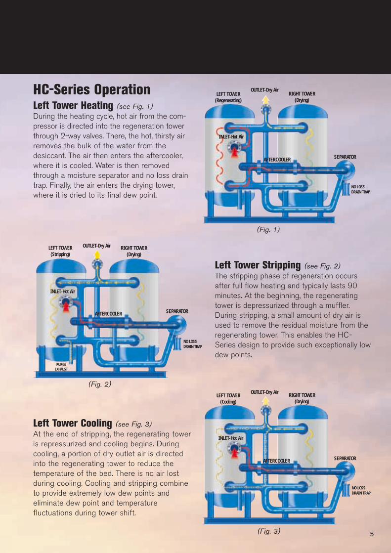
Left Tower Stripping (see Fig. 2)The stripping phase of regeneration occursafter full flow heating and typically lasts 90minutes. At the beginning, the regeneratingtower is depressurized through a muffler.During stripping, a small amount of dry air isused to remove the residual moisture from theregenerating tower. This enables the HC-Series design to provide such exceptionally lowdew points.
Left Tower Cooling (see Fig. 3)At the end of stripping, the regenerating toweris repressurized and cooling begins. Duringcooling, a portion of dry outlet air is directedinto the regenerating tower to reduce thetemperature of the bed. There is no air lostduring cooling. Cooling and stripping combineto provide extremely low dew points andeliminate dew point and temperaturefluctuations during tower shift.
5
(Fig. 1)
(Fig. 3)
(Fig. 2)
LEFT TOWER(Regenerating)
OUTLET-Dry AirRIGHT TOWER
(Drying)
SEPARATOR
NO LOSSDRAIN TRAP
INLET-Hot Air
AFTERCOOLER
HC-Series OperationLeft Tower Heating (see Fig. 1)During the heating cycle, hot air from the com-pressor is directed into the regeneration towerthrough 2-way valves. There, the hot, thirsty airremoves the bulk of the water from thedesiccant. The air then enters the aftercooler,where it is cooled. Water is then removedthrough a moisture separator and no loss draintrap. Finally, the air enters the drying tower,where it is dried to its final dew point.
LEFT TOWER(Stripping)
OUTLET-Dry Air RIGHT TOWER (Drying)
SEPARATOR
NO LOSSDRAIN TRAP
INLET-Hot Air
AFTERCOOLER
PURGEEXHAUST
LEFT TOWER(Cooling)
OUTLET-Dry Air RIGHT TOWER (Drying)
SEPARATOR
NO LOSSDRAIN TRAP
INLET-Hot Air
AFTERCOOLER

ProductivityThe problems created by moisture contamination in a compressedair system include rust and corrosion in the air piping, inadequateair tool lubrication, and damage to labeling, packaging and thefinished goods. The HOC dryer can prevent such productivitylosses throughout your operation by delivering a continuously lowdewpoint.
• The H-Series dryer can deliver points in the -18° C (0°F)to -51° C (-60° F) range depending on the operating conditions.The H-Series dryer delivers better than instrument quality air toeliminate moisture problems.
• With its patented stripping and cooling cycles, the HC-Seriesdryer can produce continuous year-round dew points of -40° C(-40° F) and below.
• Both the H- and HC-Series dryers prevent costly productioninterruptions due to moisture contamination.
Health, Safety and EnvironmentIngersoll-Rand HOC dryers are designed to protect the healthand safety of the operators and the environment in which they areinstalled.• Dryers utilize a non-acidic desiccant and no ozone depleting
refrigerants.• Insulated towers protect operators from hot surfaces.• The HOC dryer is a packaged design, with all components
pre-piped and pre-wired. This eliminates costly installationcharges and minimizes floor space requirements.
6
Technical Specifications
7
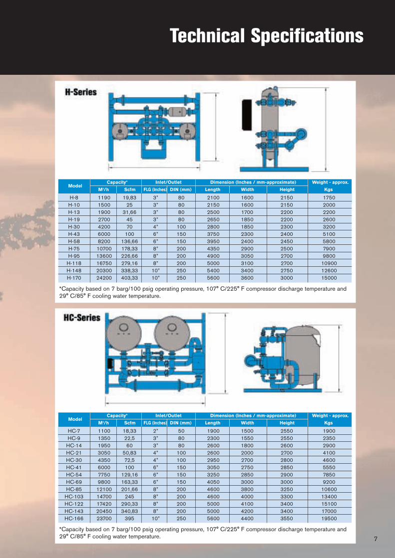
*Capacity based on 7 barg/100 psig operating pressure, 107° C/225° F compressor discharge temperature and29° C/85° F cooling water temperature.
*Capacity based on 7 barg/100 psig operating pressure, 107° C/225° F compressor discharge temperature and29° C/85° F cooling water temperature.
ModelCapacity* Inlet/Outlet Dimension (Inches / mm-approximate) Weight - approx.
M3/h Scfm FLG (Inches) DIN (mm) Length Width Height Kgs
H-8 1190 19,83 3” 80 2100 1600 2150 1750H-10 1500 25 3” 80 2150 1600 2150 2000H-13 1900 31,66 3” 80 2500 1700 2200 2200H-19 2700 45 3” 80 2650 1850 2200 2600H-30 4200 70 4” 100 2800 1850 2300 3200H-43 6000 100 6” 150 3750 2300 2400 5100H-58 8200 136,66 6” 150 3950 2400 2450 5800H-75 10700 178,33 8” 200 4350 2900 2500 7900H-95 13600 226,66 8” 200 4900 3050 2700 9800
H-118 16750 279,16 8” 200 5000 3100 2700 10900H-148 20300 338,33 10” 250 5400 3400 2750 12600H-170 24200 403,33 10” 250 5600 3600 3000 15000
ModelCapacity* Inlet/Outlet Dimension (Inches / mm-approximate) Weight - approx.
M3/h Scfm FLG (Inches) DIN (mm) Length Width Height Kgs
HC-7 1100 18,33 2” 50 1900 1500 2550 1900HC-9 1350 22,5 3” 80 2300 1550 2550 2350
HC-14 1950 60 3” 80 2600 1800 2600 2900HC-21 3050 50,83 4” 100 2600 2000 2700 4100HC-30 4350 72,5 4” 100 2950 2700 2800 4600HC-41 6000 100 6” 150 3050 2750 2850 5550HC-54 7750 129,16 6” 150 3250 2850 2900 7850HC-69 9800 163,33 6” 150 4050 3000 3000 9200HC-85 12100 201,66 8” 200 4600 3800 3250 10600
HC-103 14700 245 8” 200 4600 4000 3300 13400HC-122 17420 290,33 8” 200 5000 4100 3400 15100HC-143 20450 340,83 8” 200 5000 4200 3400 17000HC-166 23700 395 10” 250 5600 4400 3550 19500
M o r e T h a n A i r. S o l u t i o n s .Online solutions: www.air.irco.com
Ingersoll-Rand compressors are not designed, intended or approved for breathing air applications. Ingersoll-Rand does notapprove specialized equipment for breathing air applications and assumes no responsibility or liability for compressors usedfor breathing air service.
Nothing contained on these pages is intended to extend any warranty or representation, expressed or implied, regarding theproduct described herein. Any such warranties or other terms and conditions of sale of products shall be in accordance withIngersoll-Rand’s standard terms and conditions of sale for such products, which are available upon request.
Product improvement is a continuing goal at Ingersoll-Rand. Designs and specifications are subject to change without noticeor obligation.
© 01/2005 Ingersoll-Rand Company CPN 99932766 Printed in Europe
Ingersoll-Rand Co. Ltd.Chorley New RoadParagon Business ParkHorwich, BoltonGreater Manchester BL6 6JNUnited Kingdom
Heavy Industrial Air SolutionsStrada Provinciale Cassanese, 108I-20060 Vignate, Milano (Italy)
Member of
www.cagi.org


