This manual provides instructions for the installation, operation and maintenance of the Liquiflo H-Series & 3-Series gear pumps, mag-drive models H1F, H3F, H5R, H5F, H7N, H7R, H7F, H9R, H9F, 31F, 33F, 35R, 35F, 37R, 37F, 39R, 39F and 311F. It is critical for any user to read and understand the information in this manual along with any documents this manual refers to prior to installation and start-up.
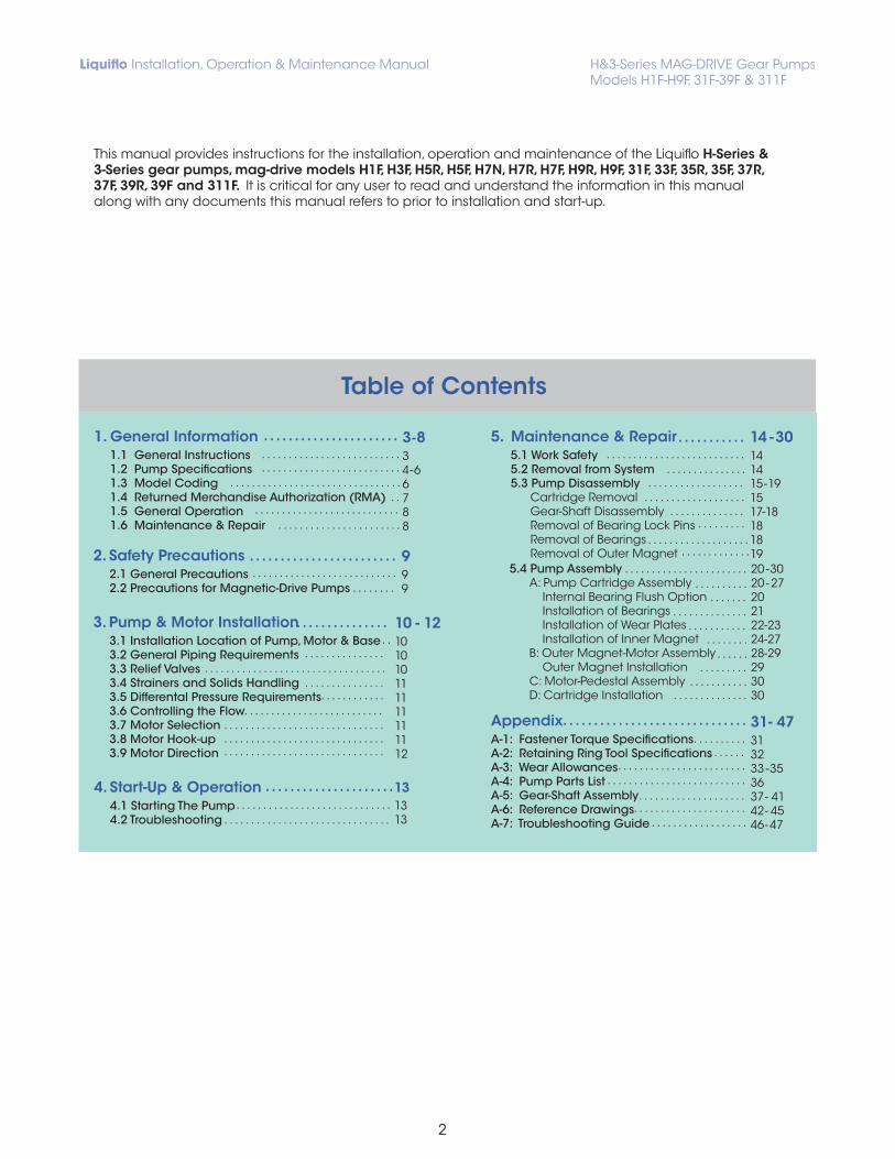
1. General Information 1.1 General Instructions 1.2 Pump Specifications 1.3 Model Coding 1.4 Returned Merchandise Authorization (RMA) 1.5 General Operation 1.6 Maintenance & Repair
3. Pump & Motor Installation3.1 Installation Location of Pump, Motor & Base3.2 General Piping Requirements3.3 Relief Valves3.4 Strainers and Solids Handling 3.5 Differental Pressure Requirements3.6 Controlling the Flow3.7 Motor Selection3.8 Motor Hook-up3.9 Motor Direction
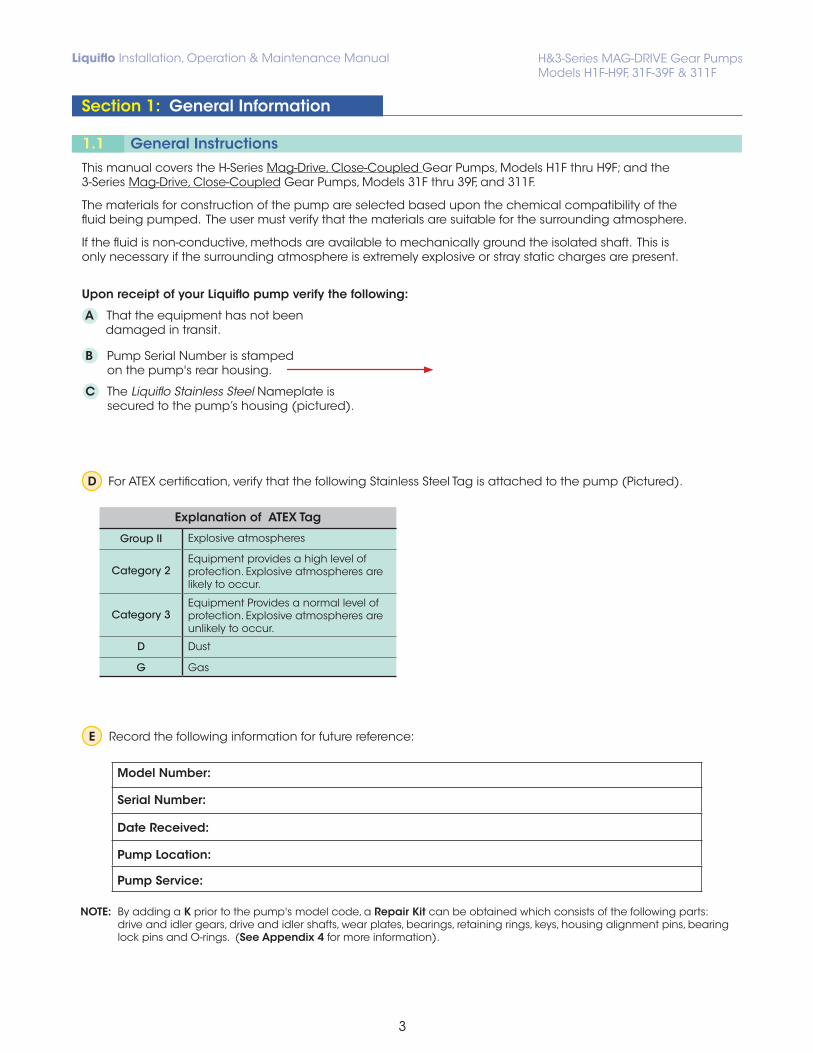
D For ATEX certification, verify that the following Stainless Steel Tag is attached to the pump (Pictured).
Explanation of ATEX Tag
Group II Explosive atmospheres
Category 2Equipment provides a high level of protection. Explosive atmospheres are likely to occur.
Category 3Equipment Provides a normal level of protection. Explosive atmospheres are unlikely to occur.
D Dust
G Gas
E Record the following information for future reference:
Model Number:
Serial Number:
Date Received:
Pump Location:
Pump Service:
NOTE: By adding a K prior to the pump's model code, a Repair Kit can be obtained which consists of the following parts: drive and idler gears, drive and idler shafts, wear plates, bearings, retaining rings, keys, housing alignment pins, bearing lock pins and O-rings. (See Appendix 4 for more information).
This manual covers the H-Series Mag-Drive, Close-Coupled Gear Pumps, Models H1F thru H9F; and the 3-Series Mag-Drive, Close-Coupled Gear Pumps, Models 31F thru 39F, and 311F.
The materials for construction of the pump are selected based upon the chemical compatibility of the fluid being pumped. The user must verify that the materials are suitable for the surrounding atmosphere.
If the fluid is non-conductive, methods are available to mechanically ground the isolated shaft. This is only necessary if the surrounding atmosphere is extremely explosive or stray static charges are present.
Upon receipt of your Liquiflo pump verify the following:
A That the equipment has not been damaged in transit.
B Pump Serial Number is stamped on the pump's rear housing.
C The Liquiflo Stainless Steel Nameplate is secured to the pump’s housing (pictured).
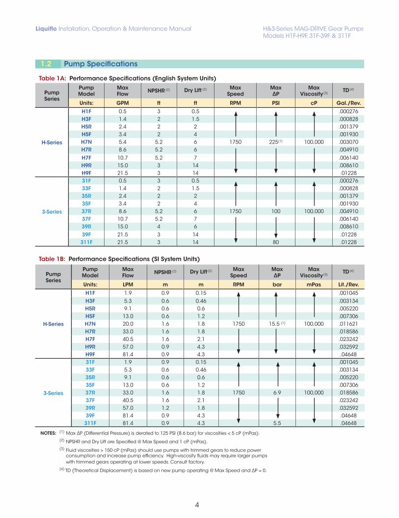
Table 1A: Performance Specifications (English System Units)
Table 1B: Performance Specifications (SI System Units)
NOTES: (1) Max ∆P (Differential Pressure) is derated to 125 PSI (8.6 bar) for viscosities < 5 cP (mPas).(2) NPSHR and Dry Lift are Specified @ Max Speed and 1 cP (mPas).(3) Fluid viscosities > 150 cP (mPas) should use pumps with trimmed gears to reduce power
consumption and increase pump efficiency. High-viscosity fluids may require larger pumps with trimmed gears operating at lower speeds. Consult factory.
(4) TD (Theoretical Displacement) is based on new pump operating @ Max Speed and ∆P = 0.
(1) MCS, MCA & MCC magnets are discontinued for new pumps and cartridges. Repair kits are still available for pumps with these magnets.
Table 3: Maximum Torque Specifications (in - lbs)When selecting a magnetically-coupled pump, the magnetic coupling must have sufficient torque transmission capability to accommodate the application. Magnet size requirements are a function of the application’s brake horsepower, RPM and temperature. If the coupling does not have sufficient strength, it will “decouple” and the pump will not rotate.
For the majority of applications a Stainless Drive gear and Plastic idler are used. The most common and most desirable material choice for the Drive Gear-Idler Gear combination is a 316 Stainless Drive Gear and PEEK idler gear. PEEK is a an extremely high performance Engineered plastic that has nearly 5 times the strength and wear properties of Teflon and is corrosion resistant to the majority of chemicals. Teflon is actually one of the least desirable material to use for gears or bearings do to its extremely weak physical properties. Because of its weak physical properties and high temperature coefficient of expansion teflon is only recommended for gears or bearings choice when no other material choice is acceptable for the application. For high viscosity liquids (in excess of 100 Cp) a Stainless Drive Gear and Alloy-20 Idler gear are acceptable. This is refered to as a double metal gear combination. The diagram below shows the relative maximum amount of torque that gears made of various materials can safely withstand. The amount of torque required is a function of both pressure and viscosity of the liquid being pumped.
NOTES: (1) The actual maximum surface temperature depends not on the pump but primarily on the temperature of the fluid being pumped. Pump surfaces will be approximately 20°F (12°C) above the temperature of the fluid being pumped. (2) For pumps with ANSI 150# RF Flanges, the Maximum Operating Pressure Rating of the flange is 285 PSIG within the temperature range of -20 to 100 °F. Above 100 °F, derate by 0.3 PSIG/°F.
Pump is designed to operate within the ambient temperature range of 32°F (0°C) and 122°F (50°C). The Pump is designed to handle fluid temperatures ranging from 32ºF (0ºC) to 104ºF (40ºC) with standard components. For fluid temperatures outside this range, gears and bearings may require a trim to compensate for thermal expansion. Reference pump model code to determine if the pump is trimmed.
Position # DescriptionPump Model Code Example: H5FS6PEE000000US
Code Selection
1 Pump Model (Size) H5 Model H5F (H5= Pump Size; F= Full Capacity2 Pump Model (Capacity) F3 Basic Material & Port Type S 316 SS Housing and Shafts & NPT Ports4 Drive Gear 6 316 SS Drive Gear5 Idler Gear P PEEK Idler Gear6 Wear Plates E Carbon-60 Wear Plates7 Bearings E Carbon-60 Bearings8 Outer Magnet Bore (Motor Frame) 0 5/8” (NEMA 56 C Motor Frame)9 Bearing Flush 0 No Bearing Flush (Standard Housings)10 Shaft Coating 0 Uncoated (Bare 316 SS Shafts)11 O-rings 0 Teflon Bearing Pins12 Retaining Rings 0 316 SS Retaining Rings13 Bearing Pins 0 Teflon Bearing Pins14 Magnetic Coupling U MCU (75 in-lbs) Magnetic Coupling15 Containment Can S Single-Wall Containment Can
Inner Magnet Casing 316 Stainless Steel or Alloy-C (2)
Outer Magnet Casing Carbon Steel/Epoxy
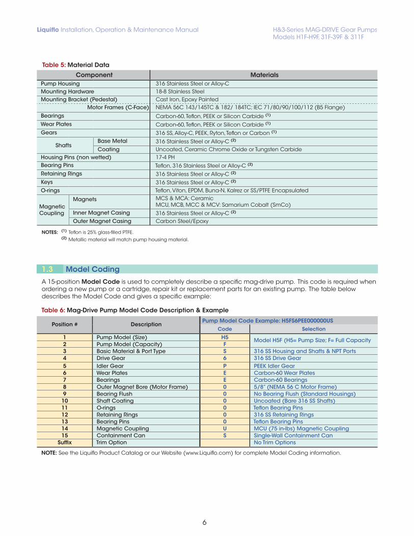
NOTES: (1) Teflon is 25% glass-filled PTFE. (2) Metallic material will match pump housing material.
1.3 Model Coding
A 15-position Model Code is used to completely describe a specific mag-drive pump. This code is required when ordering a new pump or a cartridge, repair kit or replacement parts for an existing pump. The table below describes the Model Code and gives a specific example:
Table 6: Mag-Drive Pump Model Code Description & Example
NOTE: See the Liquiflo Product Catalog or our Website (www.Liquiflo.com) for complete Model Coding information.
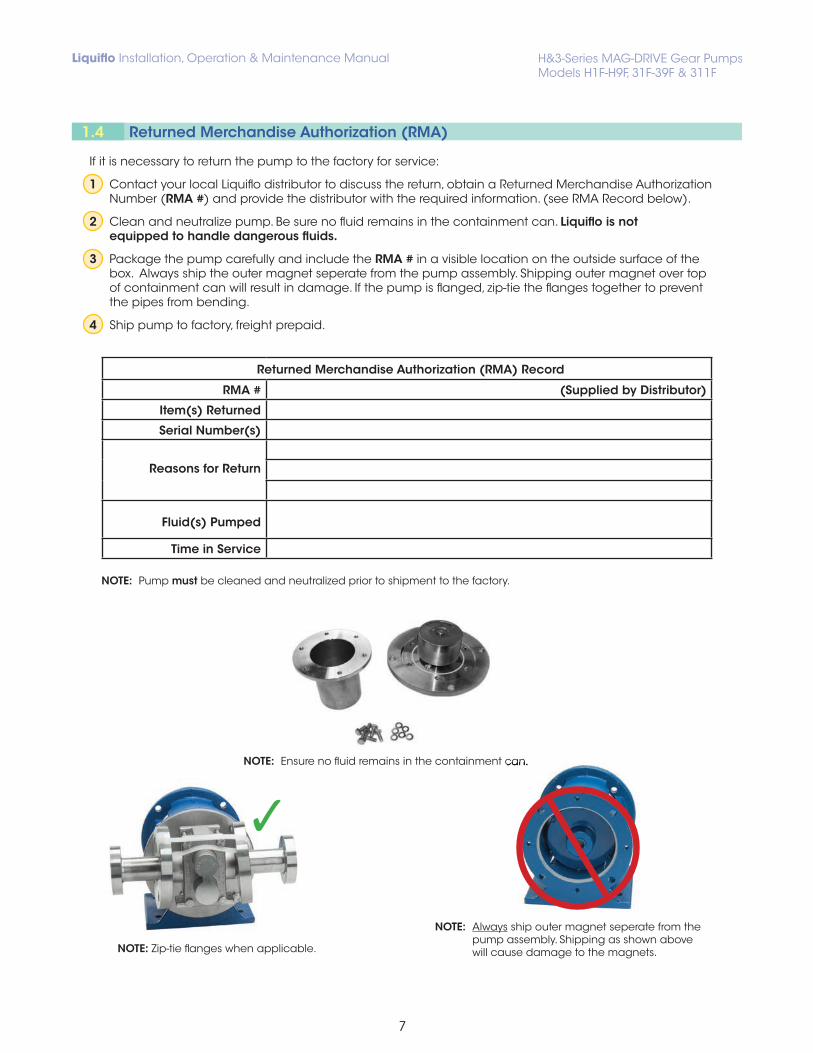
NOTE: Pump must be cleaned and neutralized prior to shipment to the factory.
NOTE: Ensure no fluid remains in the containment can.Ensure no fluid remains in the containment can.
NOTE: Always ship outer magnet seperate from the pump assembly. Shipping as shown above will cause damage to the magnets.NOTE: Zip-tie flanges when applicable.
If it is necessary to return the pump to the factory for service:
1 Contact your local Liquiflo distributor to discuss the return, obtain a Returned Merchandise Authorization Number (RMA #) and provide the distributor with the required information. (see RMA Record below).
2 Clean and neutralize pump. Be sure no fluid remains in the containment can. Liquiflo is not equipped to handle dangerous fluids.
3 Package the pump carefully and include the RMA # in a visible location on the outside surface of the box. Always ship the outer magnet seperate from the pump assembly. Shipping outer magnet over top of containment can will result in damage. If the pump is flanged, zip-tie the flanges together to prevent the pipes from bending.
The successful and safe operation of a pump is not only dependent on the pump but also on each of the system components. It is therefore important to monitor the entire pumping system during operation and to perform the necessary maintenance to keep the system running smoothly.
A normally operating magnetic-drive gear pump will deliver a steady, pulse-less flow with no leakage, be relatively quiet and have a predictable flow rate based on the pump speed, fluid viscosity and differential pressure across the pump. Refer to the performance curves of the specific pump model being operated (see Liquiflo Product Catalog or website: www.liquiflo.com).
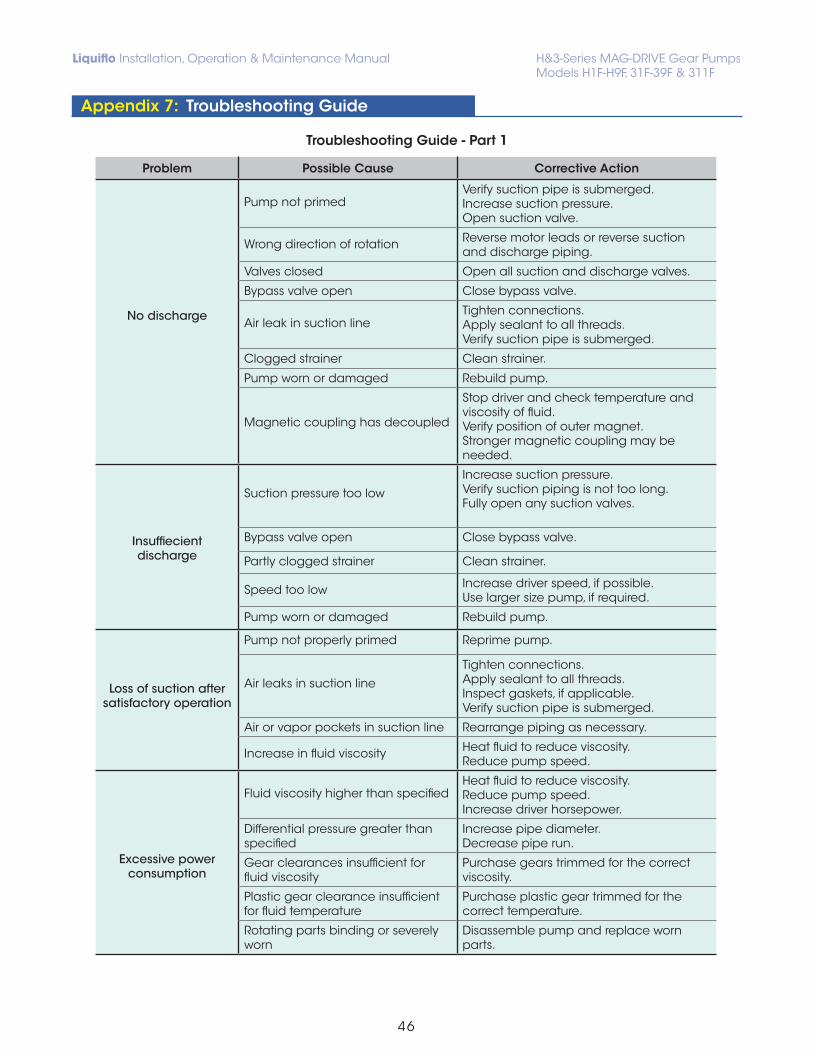
If a significant problem is observed during operation, the pump should be stopped so that corrective action can be taken. The observed problem could have several possible causes, and multiple remedies for each cause. For help with problem solving, refer to the Troubleshooting Guide given in Appendix 7.
The pump has internal sleeve bearings, wear plates, gears and shafts which require replacement over time due to physical wear. The center housing of the pump may also incur physical wear and require replacement (see Appendix 3). O-rings and retaining rings should always be replaced when rebuilding the pump.
The main factors affecting the physical wear of the pump are operating speed, differential pressure, fluid viscosity, duty cycle, starting and stopping frequency, abrasives in the fluid and the wear properties of the materials. These factors can cause pump lifetimes to vary significantly from one application to another, making it difficult to predict when the pump will require maintenance. Therefore, the maintenance schedule for the pump is typically based on the maintenance history of the specific application. The main indicators that a pump may require maintenance are the following: (1) decreased flow rate or pressure, (2) fluid leakage, (3) unusual noise or vibrations and (4) increased power consumption.
Standard repair kits are available to facilitate repair of the pump (see Appendix 4). A repair kit includes all inter-nal wear parts as well as O-rings, retaining rings, bearing lock pins, housing alignment pins and keys. The parts not included in a mag-drive pump repair kit are the housings (front, center and rear), magnets (inner and outer), containment can, pedestal and hardware (bolts, nuts and washers). Before performing maintenance on the pump, review the safety precautions and follow the included instructions.
Caution!Failure to observe safety precautions can result in personal injury, equipment damage or malfunction.
Caution!• Individuals with cardiac pacemakers should avoid repairs on these units.
• Individuals with internal wound clips, metallic wiring, or other metallic prosthetic devices should avoid repairs on these units.
• Strong magnetic fields can cause tools and parts to slam together,injuring hands and fingers.
Strong magnets will attract iron, cast iron, carbon steel and some types of stainless steel. Keep magnets away from credit cards, computers, computer discs and watches.
• Always lock out the power to the pump driver when performing maintenance on the pump.
• Always lock out the suction and discharge valves when performing maintenance on the pump.
• Never use heat to disassemble pump.
• Before performing maintenance on the pump, check with appropriate personnel to determine if skin, eye or lung protection is required and how best to flush the pump.
2.2 Precautions for Magnetic-Drive PumpsMagnetic-drive pumps contain strong magnets, which pose health risks. Based on this, the following must be observed:
Refer to the Hydraulic Institute Standards for installation procedures of the base, pump and motor.
1 The pump inlet should be as close to the liquid source as practical and preferably below it. Even though gear pumps have self priming and lift capability, many issues can be avoided with a flooded suction configuration.
Caution!Do not use the pump to support the piping or allow the piping to apply stress to the pump ports. This can distort the alignment of the pump housing with internal parts and lead to rapid wear or malfunction.
2 Piping that handles both hot and cold liquids require proper installation of expansion loops and joints so that thermal expansion of the piping will not cause misalignment.
3 Suction and discharge piping should be the same size or larger than the inlet and outlet ports. This is especially important for viscous services when the pipe diameter has a large effect on friction losses and NPSH available.
3.1 Installation Location of Pump, Motor & Base
NOTE: The pump models covered in this manual are close-coupled and no alignment procedure between the pump and motor is required.
3.2 General Piping Requirements
Refer to Hydraulic Institute Standards for piping guidelines.
1 All piping must be supported independently and must line up naturally with pump ports.
1 A positive displacement pump should have a pressure relief valve installed in the discharge line. Operating a gear pump against a closed discharge valve will result in over pressure and likely failure of the pump or system. Install the relief valve between the pump discharge port and the discharge isolation valve Ideally, the relief valve should bypass the discharge line back to the supply tank. Where this is not feasible, piping the relief valve back to the suction side of the pump will prevent immediate pump failure from over pressure, however, continuously running in this condition will cause heating of the fluid.
1 The motor frame must be compatible with the pump mounting bracket (pedestal) and outer magnet hub. The motor frame size is part of the pump model coding and is selected at the time the pump is ordered. Pedestals and hubs are available to fit NEMA 56C, 143TC, 145TC, 182TC & 184TC, and IEC 71, 80, 90, 100 & 112 (with B5 flange). NEMA 182/184TC and IEC 100 & 112 B5 motor frames require an adapter plate to mount the motor to the bracket (see Page 29). The adapter plate is provided when required.
2 The motor is often sized at the time the pump is ordered to meet the specified conditions of service. The power requirements of the application depend on the flow rate, differential pressure and fluid viscosity. Up to 100cP, the pump performance charts can be used to determine the brake horse power (BHP) required for the application. Motor sizing and selection is further influenced by: mag-drive eddy current losses, constant torque ratios, enclosure requirements and RPM limits due to viscosity. For sizing of viscous fluid applications or for more assistance in general selection, contact the local distributor or Liquiflo.
Please refer to the motor manufacturers instructions.
3.5 Differental Pressure Requirements The pump should be operated with at least 15 PSI (1 bar) differential pressure to ensure that fluid is forced into the sleeve bearings, which are lubricated by the pumped fluid. If adequate discharge pressure is not available, a back pressure valve can be used to generate sufficient pressure.
1 Liquiflo gear pumps have very close internal clearances and are designed to pump relatively clean fluids. The entrance of foreign material could cause damage or rapid wear to the pump components. While occa- sional small particles may not be catastrophic to the pump, the use of a strainer on the inlet will prevent large particulates from entering the pump. Large particulates can become lodged into the roots of the gears, causing a sudden failure. If small, abrasive particles are present, they can get in between the shaft and bearings which will accelerate or increase wear over an extended period of time. If the strainer clogs with material and is not properly maintained, the pump may be starved of liquid, causing a loss of flow and damaging the pump via dry-running or cavitation.
2 Regardless of particle size, these pumps are intended for relatively clean liquids where the general concen- tration of solids is limited to 1% by volume. Higher concentration may cause the wear rate to increase, resulting in a decrease in pump performance. In addition to solids concentration, the specific wear rate also depends on the size, shape and hardness of the particles, the operating speed and the materials used to construct the pump. Since wear rate is proportional to the square of the speed, slower operating speeds will substantially increase pump life.
A gear pump is a positive displacement pump, and flow cannot be controlled by throttling the discharge valve. Adjusting the motor speed using a VFD (Variable Frequency Drive) is the most common method to control flow. Fluid viscosity and differential pressure will also have an affect on the flow rate.
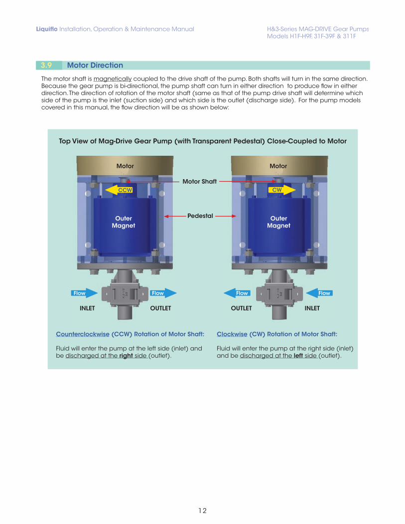
Top View of Mag-Drive Gear Pump (with Transparent Pedestal) Close-Coupled to Motor
Counterclockwise (CCW) Rotation of Motor Shaft:
Fluid will enter the pump at the left side (inlet) and be discharged at the right side (outlet).
Clockwise (CW) Rotation of Motor Shaft:
Fluid will enter the pump at the right side (inlet) and be discharged at the left side (outlet).
Flow
Motor
OUTLET INLET
OuterMagnet
Flow
CW
Flow
Motor
INLET OUTLET
OuterMagnet
Flow
CCW
Pedestal
Motor Shaft
The motor shaft is magnetically coupled to the drive shaft of the pump. Both shafts will turn in the same direction. Because the gear pump is bi-directional, the pump shaft can turn in either direction to produce flow in either direction. The direction of rotation of the motor shaft (same as that of the pump drive shaft will determine which side of the pump is the inlet (suction side) and which side is the outlet (discharge side). For the pump models covered in this manual, the flow direction will be as shown below:
1 Verify that the pump and motor are suitable for the conditions of service.
2 Verify that all suction and discharge valves are open before starting the pump.
3 Prime the pump if feasible. For a flooded suction, allow the fluid time to enter the pump. While the pump is capable of pulling a dry lift, wear occurs during this period. For a suction lift, priming or wetting the internal parts greatly reduces wear, since the components are lubricated by the pumped fluid. Furthermore, some material combinations, such as PEEK gears and Carbon wear plates and bearings are much more forgiving to short periods of dry running. For this reason, a general rule is to not run the pump dry for more than 30 seconds.
4 Jog the motor to check the rotation (see Page 12 for diagram).
5 Monitor the pump for several minutes to insure proper operation.
A normally operating magnetic-drive gear pump will deliver a steady, pulse-less flow with no leakage, be relatively quiet and have a predictable flow rate based on the pump speed, fluid viscosity and differential pressure across the pump. Refer to the performance curves of the specific pump model being operated (see Liquiflo Product Catalog or website: www.liquiflo.com).
During pump operation, inspect for: (1) Unusual noise, (2) Product leakage, (3) Expected suction and discharge pressures and (4) Expected flow rate based on pump speed, fluid viscosity and differential pressure. If any problems occur, stop the pump and take corrective action. For help with problem solving, refer to the Troubleshooting Guide given in Appendix 7.
The pump has internal sleeve bearings, wear plates, gears and shafts which require replacement over time due to physical wear. The center housing of the pump may also incur physical wear and require replacement (see Appendix 3 for Wear Allowances). O-rings and retaining rings should always be replaced when rebuilding the pump.
Section 5: Maintenance & Repair
1) Flush the pump.
2) Stop the motor and lock out the electrical panel.
3) Close the suction and discharge isolation valves.
4) Disconnect the pump from the system piping.
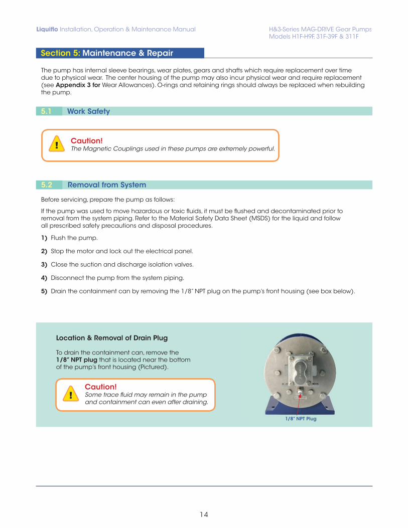
5) Drain the containment can by removing the 1/8” NPT plug on the pump’s front housing (see box below).
Caution!The Magnetic Couplings used in these pumps are extremely powerful.
Caution!Some trace fluid may remain in the pump and containment can even after draining.
Location & Removal of Drain Plug
To drain the containment can, remove the 1/8” NPT plug that is located near the bottom of the pump’s front housing (Pictured).
1/8” NPT Plug
5.1 Work Safety
5.2 Removal from System
Before servicing, prepare the pump as follows:
If the pump was used to move hazardous or toxic fluids, it must be flushed and decontaminated prior to removal from the system piping. Refer to the Material Safety Data Sheet (MSDS) for the liquid and follow all prescribed safety precautions and disposal procedures.
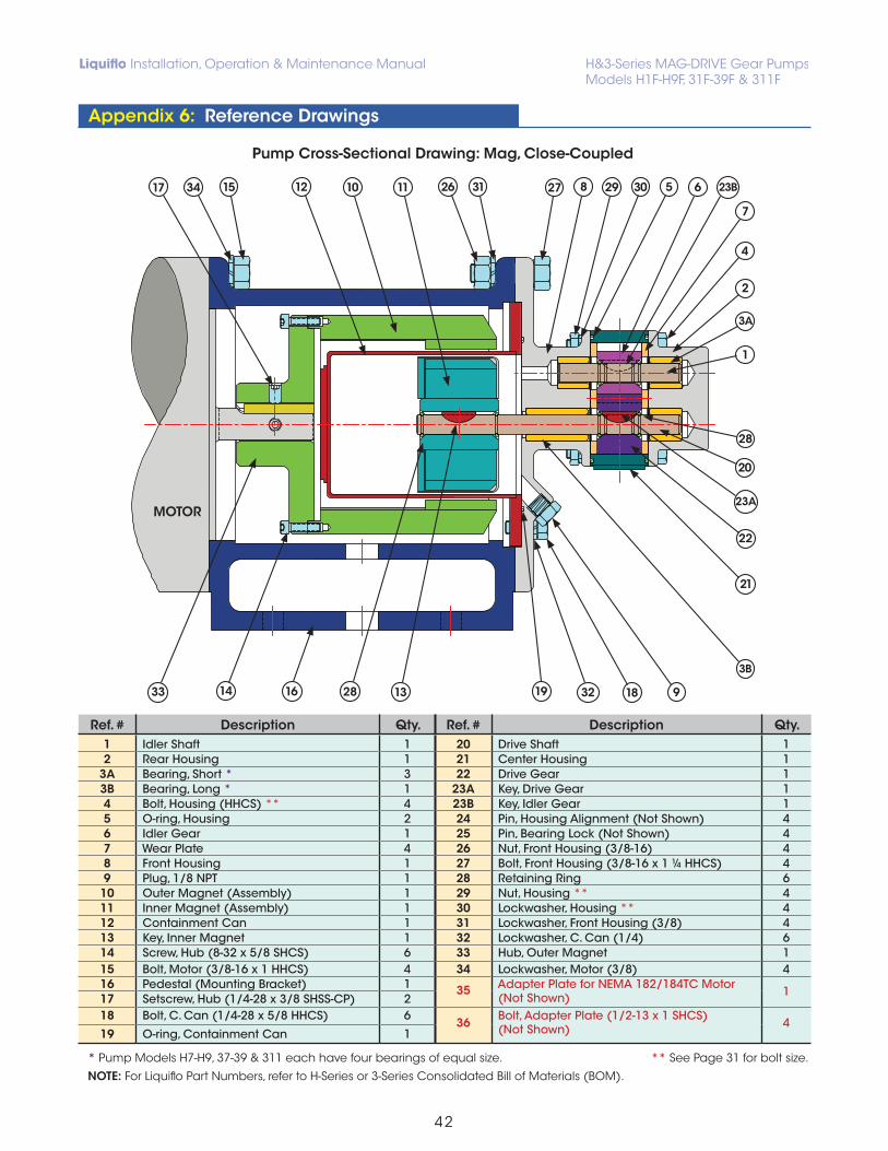
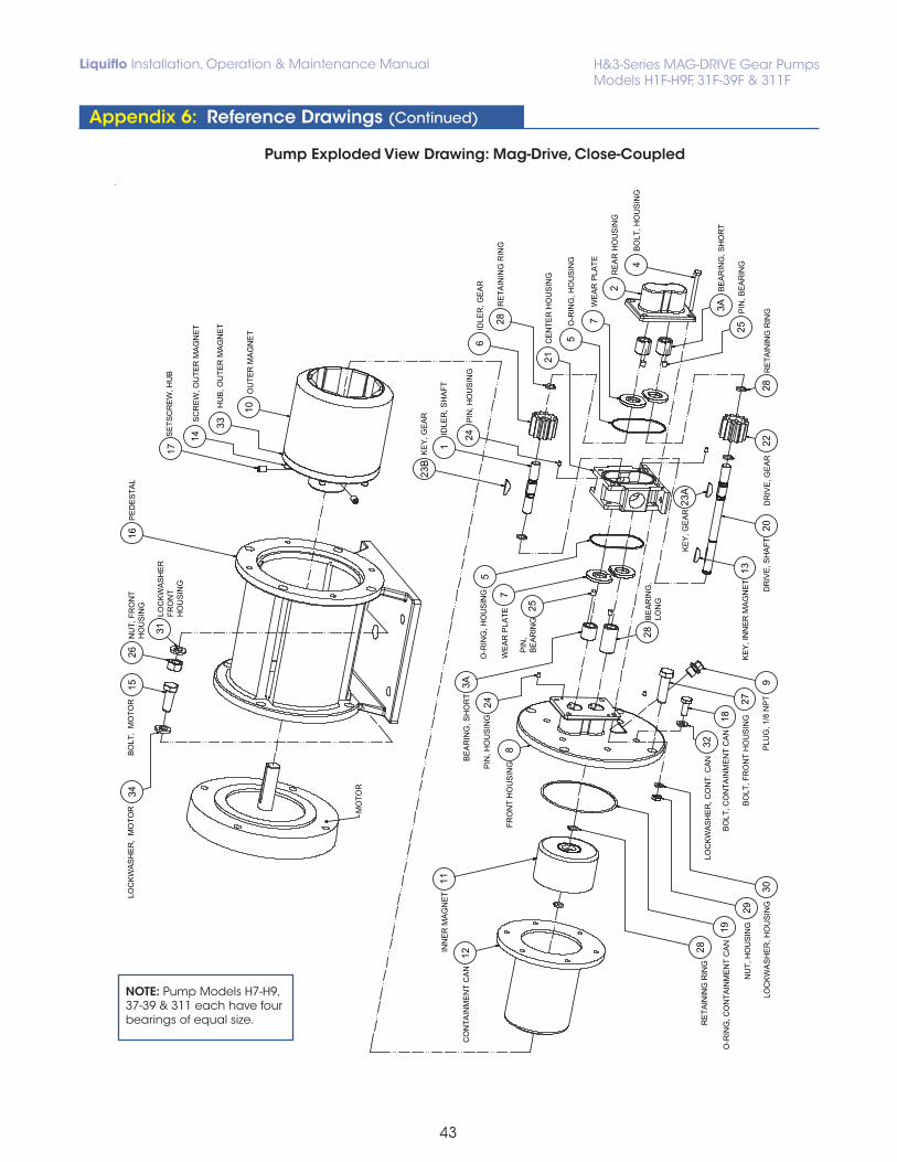
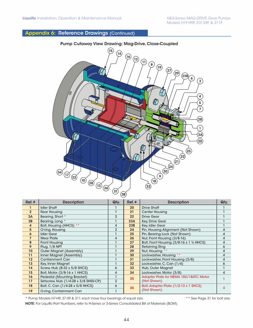
Follow the procedure below and refer to the drawings in Appendix 6.
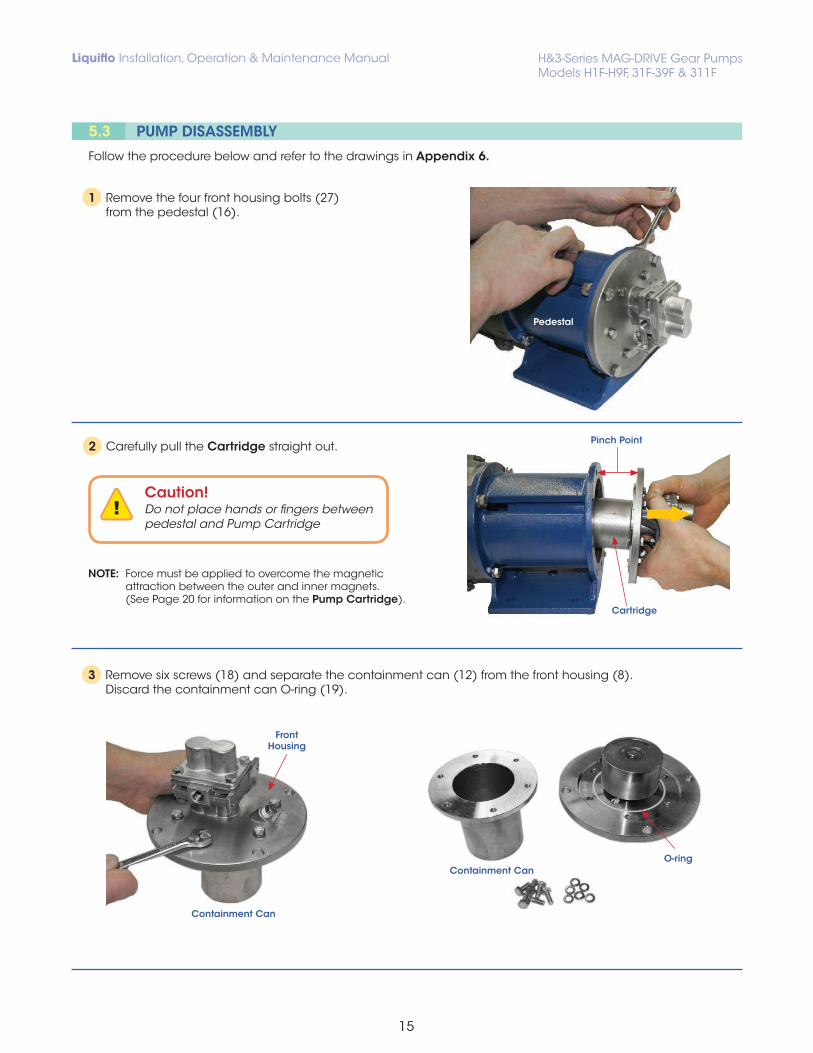
1 Remove the four front housing bolts (27) from the pedestal (16).
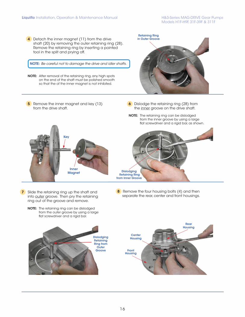
2 Carefully pull the Cartridge straight out.
3 Remove six screws (18) and separate the containment can (12) from the front housing (8). Discard the containment can O-ring (19).
NOTE: Force must be applied to overcome the magnetic attraction between the outer and inner magnets. (See Page 20 for information on the Pump Cartridge).
Caution!Do not place hands or fingers between pedestal and Pump Cartridge
4 Detach the inner magnet (11) from the drive shaft (20) by removing the outer retaining ring (28). Remove the retaining ring by inserting a pointed tool in the split and prying off.
8 Remove the four housing bolts (4) and then separate the rear, center and front housings.
7 Slide the retaining ring up the shaft and into outer groove. Then pry the retaining ring out of the groove and remove.
5 Remove the inner magnet and key (13) from the drive shaft.
NOTE: After removal of the retaining ring, any high spots on the end of the shaft must be polished smooth so that the of the inner magnet is not inhibited.
6 Dislodge the retaining ring (28) from the inner groove on the drive shaft.
NOTE: The retaining ring can be dislodged from the inner groove by using a large flat screwdriver and a rigid bar, as shown.
NOTE: The retaining ring can be dislodged from the outer groove by using a large flat screwdriver and a rigid bar.
NOTE: Be careful not to damage the drive and idler shafts.
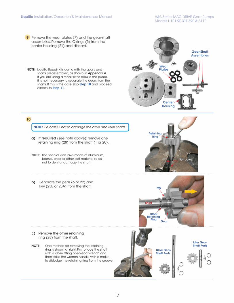
9 Remove the wear plates (7) and the gear-shaft assemblies. Remove the O-rings (5) from the center housing (21) and discard.
10
NOTE: Liquiflo Repair Kits come with the gears and shafts preassembled, as shown in Appendix 4. If you are using a repair kit to rebuild the pump, it is not necessary to separate the gears from the shafts. If this is the case, skip Step 10 and proceed directly to Step 11.
a) If required (see note above): remove one retaining ring (28) from the shaft (1 or 20).
b) Separate the gear (6 or 22) and key (23B or 23A) from the shaft.
NOTE: Be careful not to damage the drive and idler shafts.
Wear Plates
Gear-ShaftAssemblies
Center Housing
Soft Jaws
Retaining Ring
Key
Shaft
Gear
OtherRetaining
Ring
c) Remove the other retaining ring (28) from the shaft.
NOTE: One method for removing the retaining ring is shown at right. First bridge the shaft with a close fitting open-end wrench and then strike the wrench handle with a mallet to dislodge the retaining ring from the groove.
Drive Gear- Shaft Parts
Idler Gear- Shaft Parts
NOTE: Use special vice jaws made of aluminum, bronze, brass or other soft material so as not to dent or damage the shaft.
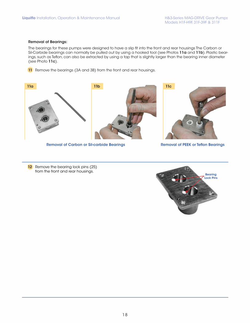
The bearings for these pumps were designed to have a slip fit into the front and rear housings The Carbon or Sil-Carbide bearings can normally be pulled out by using a hooked tool (see Photos 11a and 11b). Plastic bear-ings, such as Teflon, can also be extracted by using a tap that is slightly larger than the bearing inner diameter (see Photo 11c).
11 Remove the bearings (3A and 3B) from the front and rear housings.
11a 11b 11c
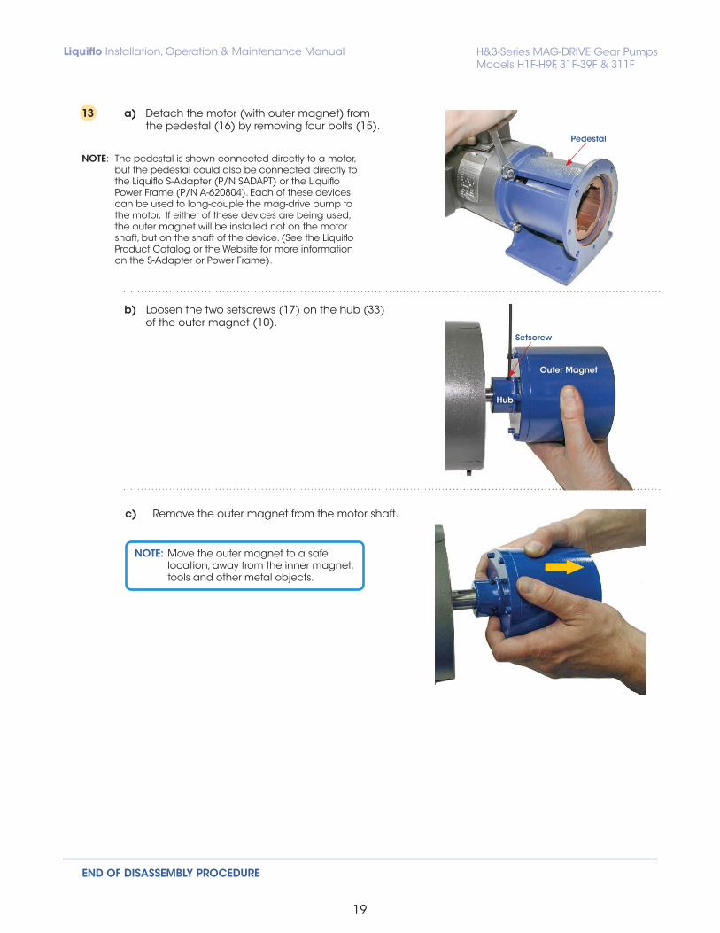
12 Remove the bearing lock pins (25) from the front and rear housings.
Removal of Carbon or Sil-carbide Bearings Removal of PEEK or Teflon Bearings
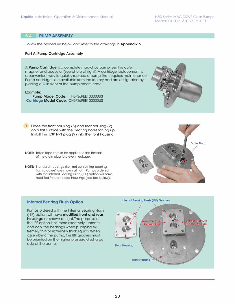
13 a) Detach the motor (with outer magnet) from the pedestal (16) by removing four bolts (15).
b) Loosen the two setscrews (17) on the hub (33) of the outer magnet (10).
c) Remove the outer magnet from the motor shaft.
Pedestal
Outer Magnet
Setscrew
Hub
END OF DISASSEMBLY PROCEDURE
NOTE: The pedestal is shown connected directly to a motor, but the pedestal could also be connected directly to the Liquiflo S-Adapter (P/N SADAPT) or the Liquiflo Power Frame (P/N A-620804). Each of these devices can be used to long-couple the mag-drive pump to the motor. If either of these devices are being used, the outer magnet will be installed not on the motor shaft, but on the shaft of the device. (See the Liquiflo Product Catalog or the Website for more information on the S-Adapter or Power Frame).
NOTE: Move the outer magnet to a safe location, away from the inner magnet, tools and other metal objects.
Follow the procedure below and refer to the drawings in Appendix 6.
A Pump Cartridge is a complete mag-drive pump less the outer magnet and pedestal (see photo at right). A cartridge replacement is a convenient way to quickly replace a pump that requires maintenance. Pump cartridges are available from the factory and are designated by placing a C in front of the pump model code.
Example: Pump Model Code: H5FS6PEE100000US Cartridge Model Code: CH5FS6PEE100000US
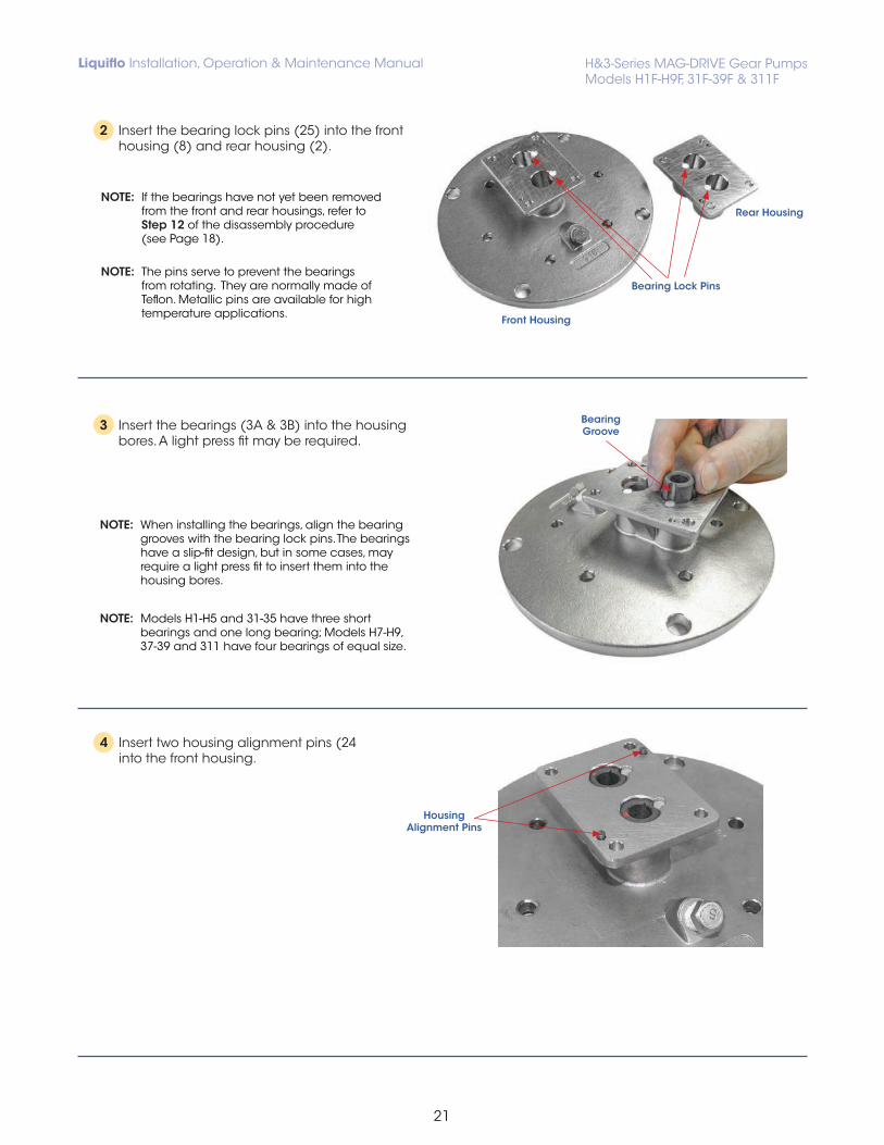
1 Place the front housing (8) and rear housing (2) on a flat surface with the bearing bores facing up. Install the 1/8” NPT plug (9) into the front housing.
NOTE: Teflon tape should be applied to the threads of the drain plug to prevent leakage.
NOTE: Standard housings (i.e., not containing bearing flush grooves) are shown at right. Pumps ordered with the Internal Bearing Flush (IBF) option will have modified front and rear housings (see box below).
Drain Plug
Internal Bearing Flush Option
Pumps ordered with the Internal Bearing Flush (IBF) option will have modified front and rear housings, as shown at right. The purpose of the IBF option is to more effectively lubrcate and cool the bearings when pumping ex-tremely thin or extremely thick liquids. When assembling the pump, the IBF grooves must be oriented on the higher pressure discharge side of the pump.
4 Insert two housing alignment pins (24 into the front housing.
Bearing Lock Pins
Rear Housing
Front Housing
HousingAlignment Pins
NOTE: If the bearings have not yet been removed from the front and rear housings, refer to Step 12 of the disassembly procedure (see Page 18).
NOTE: The pins serve to prevent the bearings from rotating. They are normally made of Teflon. Metallic pins are available for high temperature applications.
3 Insert the bearings (3A & 3B) into the housing bores. A light press fit may be required.
NOTE: When installing the bearings, align the bearing grooves with the bearing lock pins. The bearings have a slip-fit design, but in some cases, may require a light press fit to insert them into the housing bores.
NOTE: Models H1-H5 and 31-35 have three short bearings and one long bearing; Models H7-H9, 37-39 and 311 have four bearings of equal size.
2 Insert the bearing lock pins (25) into the front housing (8) and rear housing (2).
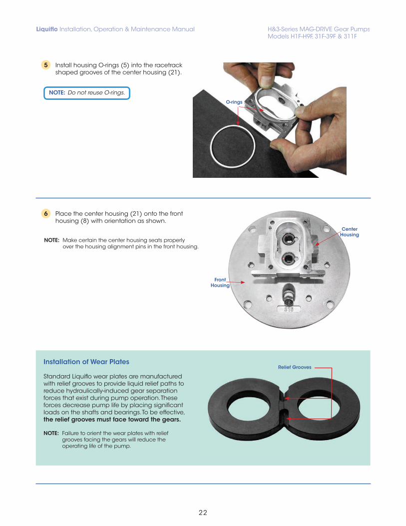
5 Install housing O-rings (5) into the racetrack shaped grooves of the center housing (21).
6 Place the center housing (21) onto the front housing (8) with orientation as shown.
NOTE: Make certain the center housing seats properly over the housing alignment pins in the front housing.
Center Housing
Front Housing
O-rings
Installation of Wear Plates
Standard Liquiflo wear plates are manufactured with relief grooves to provide liquid relief paths to reduce hydraulically-induced gear separation forces that exist during pump operation. These forces decrease pump life by placing significant loads on the shafts and bearings. To be effective, the relief grooves must face toward the gears. NOTE: Failure to orient the wear plates with relief grooves facing the gears will reduce the operating life of the pump.
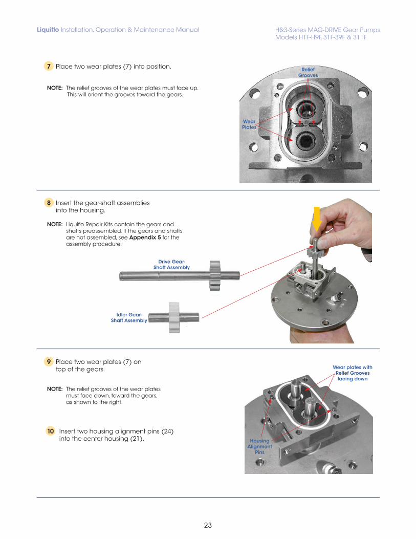
NOTE: The relief grooves of the wear plates must face up. This will orient the grooves toward the gears.
8 Insert the gear-shaft assemblies into the housing.
NOTE: Liquiflo Repair Kits contain the gears and shafts preassembled. If the gears and shafts are not assembled, see Appendix 5 for the assembly procedure.
9 Place two wear plates (7) on top of the gears.
NOTE: The relief grooves of the wear plates must face down, toward the gears, as shown to the right.
10 Insert two housing alignment pins (24) into the center housing (21).
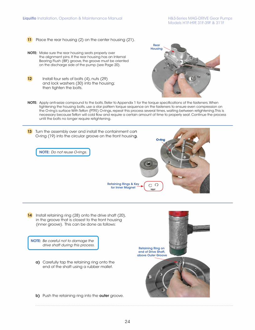
11 Place the rear housing (2) on the center housing (21).
NOTE: Make sure the rear housing seats properly over the alignment pins. If the rear housing has an Internal Bearing Flush (IBF) groove, the groove must be oriented on the discharge side of the pump (see Page 20).
12 Install four sets of bolts (4), nuts (29) and lock washers (30) into the housing; then tighten the bolts.
13 Turn the assembly over and install the containment can O-ring (19) into the circular groove on the front housing.
14 Install retaining ring (28) onto the drive shaft (20), in the groove that is closest to the front housing (inner groove). This can be done as follows:
a) Carefully tap the retaining ring onto the end of the shaft using a rubber mallet.
b) Push the retaining ring into the outer groove.
NOTE: Be careful not to damage the drive shaft during this process.
Retaining Ring on end of Drive Shaft,
above Outer Groove
O-ring
RearHousing
Turn the assembly over and install the containment can O-ring (19) into the circular groove on the front housing.
O-ring
Retaining Rings & Key for Inner Magnet
NOTE: Apply anti-seize compound to the bolts. Refer to Appendix 1 for the torque specifications of the fasteners. When tightening the housing bolts, use a star pattern torque sequence on the fasteners to ensure even compression on the O-ring’s surface With Teflon (PTFE) O-rings, repeat this process several times, waiting between retightening.This is necessary because Teflon will cold flow and require a certain amount of time to properly seat. Continue the process until the bolts no longer require retightening.
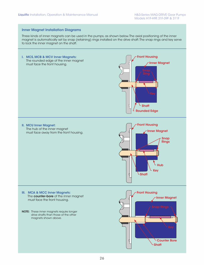
Three kinds of inner magnets can be used in the pumps, as shown below. The axial positioning of the inner magnet is automatically set by snap (retaining) rings installed on the drive shaft. The snap rings and key serve to lock the inner magnet on the shaft.
I. MCS, MCB & MCV Inner Magnets: The rounded edge of the inner magnet must face the front housing.
II. MCU Inner Magnet: The hub of the inner magnet must face away from the front housing.
III. MCA & MCC Inner Magnets: The counter - bore of the inner magnet must face the front housing.
NOTE: These inner magnets require longer drive shafts than those of the other magnets shown above.
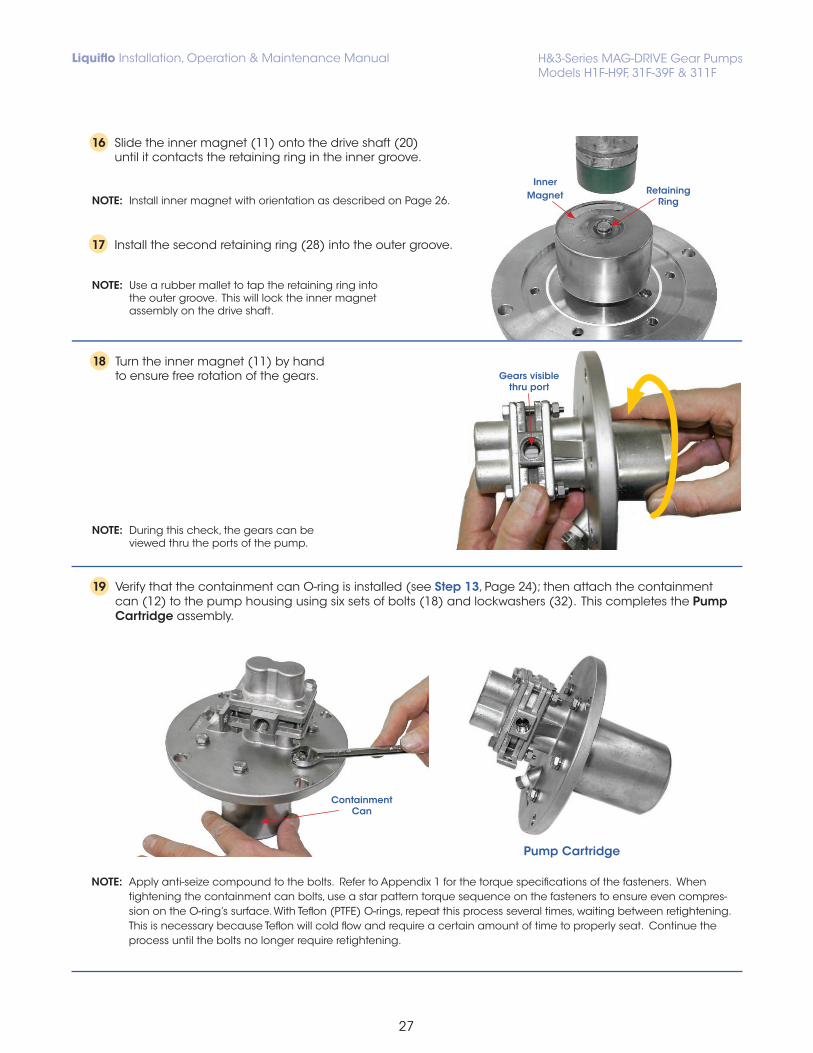
16 Slide the inner magnet (11) onto the drive shaft (20) until it contacts the retaining ring in the inner groove.
NOTE: Install inner magnet with orientation as described on Page 26.
17 Install the second retaining ring (28) into the outer groove.
NOTE: Use a rubber mallet to tap the retaining ring into the outer groove. This will lock the inner magnet assembly on the drive shaft.
18 Turn the inner magnet (11) by hand to ensure free rotation of the gears.
19 Verify that the containment can O-ring is installed (see Step 13, Page 24); then attach the containment can (12) to the pump housing using six sets of bolts (18) and lockwashers (32). This completes the Pump Cartridge assembly.
NOTE: Apply anti-seize compound to the bolts. Refer to Appendix 1 for the torque specifications of the fasteners. When tightening the containment can bolts, use a star pattern torque sequence on the fasteners to ensure even compres- sion on the O-ring’s surface. With Teflon (PTFE) O-rings, repeat this process several times, waiting between retightening. This is necessary because Teflon will cold flow and require a certain amount of time to properly seat. Continue the process until the bolts no longer require retightening.
ContainmentCan
Pump Cartridge
InnerMagnet Retaining
Ring
Gears visible thru port
NOTE: During this check, the gears can be viewed thru the ports of the pump.
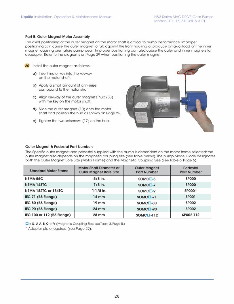
a) Insert motor key into the keyway on the motor shaft.
b) Apply a small amount of anti-seize compound to the motor shaft.
c) Align keyway of the outer magnet’s hub (33) with the key on the motor shaft.
d) Slide the outer magnet (10) onto the motor shaft and position the hub as shown on Page 29.
e) Tighten the two setscrews (17) on the hub.
The Specific outer magnet and pedestal supplied with the pump is dependent on the motor frame selected; the outer magnet also depends on the magnetic coupling size (see table below). The pump Model Code designates both the Outer Magnet Bore Size (Motor Frame) and the Magnetic Coupling Size (see Table 6, Page 6).
shaft and position the hub as shown on Page 29.
Standard Motor Frame Motor Shaft Diameter or Outer Magnet Bore Size
Outer MagnetPart Number
Pedestal Part Number
NEMA 56C 5/8 in. SOMC -5 SP000
NEMA 143TC 7/8 in. SOMC -7 SP000
NEMA 182TC or 184TC 1-1/8 in. SOMC -9 SP000*
IEC 71 (B5 Flange) 14 mm SOMC -71 SP001
IEC 80 (B5 Flange) 19 mm SOMC -80 SP002
IEC 90 (B5 Flange) 24 mm SOMC -90 SP002
IEC 100 or 112 (B5 Flange) 28 mm SOMC -112 SP002-112
= S, U, A, B, C or V (Magnetic Coupling Size; see Table 3, Page 5.)
* Adapter plate required (see Page 29).
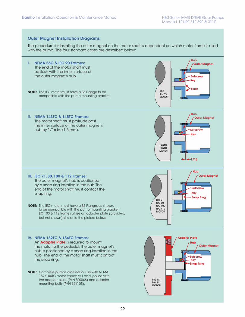
The axial positioning of the outer magnet on the motor shaft is critical to pump performance. Improper positioning can cause the outer magnet to rub against the front housing or produce an axial load on the inner magnet, causing premature pump wear. Improper positioning can also cause the outer and inner magnets to decouple. Refer to the diagrams on Page 29 when positioning the outer magnet.
The procedure for installing the outer magnet on the motor shaft is dependent on which motor frame is used with the pump. The four standard cases are described below:
I. NEMA 56C & IEC 90 Frames: The end of the motor shaft must be flush with the inner surface of the outer magnet’s hub.
NOTE: The IEC motor must have a B5 Flange to be compatible with the pump mounting bracket.
II. NEMA 143TC & 145TC Frames: The motor shaft must protrude past the inner surface of the outer magnet’s hub by 1/16 in. (1.6 mm).
III. IEC 71, 80, 100 & 112 Frames: The outer magnet’s hub is positioned by a snap ring installed in the hub. The end of the motor shaft must contact the snap ring.
NOTE: The IEC motor must have a B5 Flange, as shown, to be compatible with the pump mounting bracket EC 100 & 112 frames utilize an adapter plate (provided, but not shown) similar to the picture below.
IV. NEMA 182TC & 184TC Frames: An Adapter Plate is required to mount the motor to the pedestal. The outer magnet’s hub is positioned by a snap ring installed in the hub. The end of the motor shaft must contact the snap ring.
NOTE: Complete pumps ordered for use with NEMA 182/184TC motor frames will be supplied with the adapter plate (P/N SP0046) and adapter mounting bolts (P/N 641105).
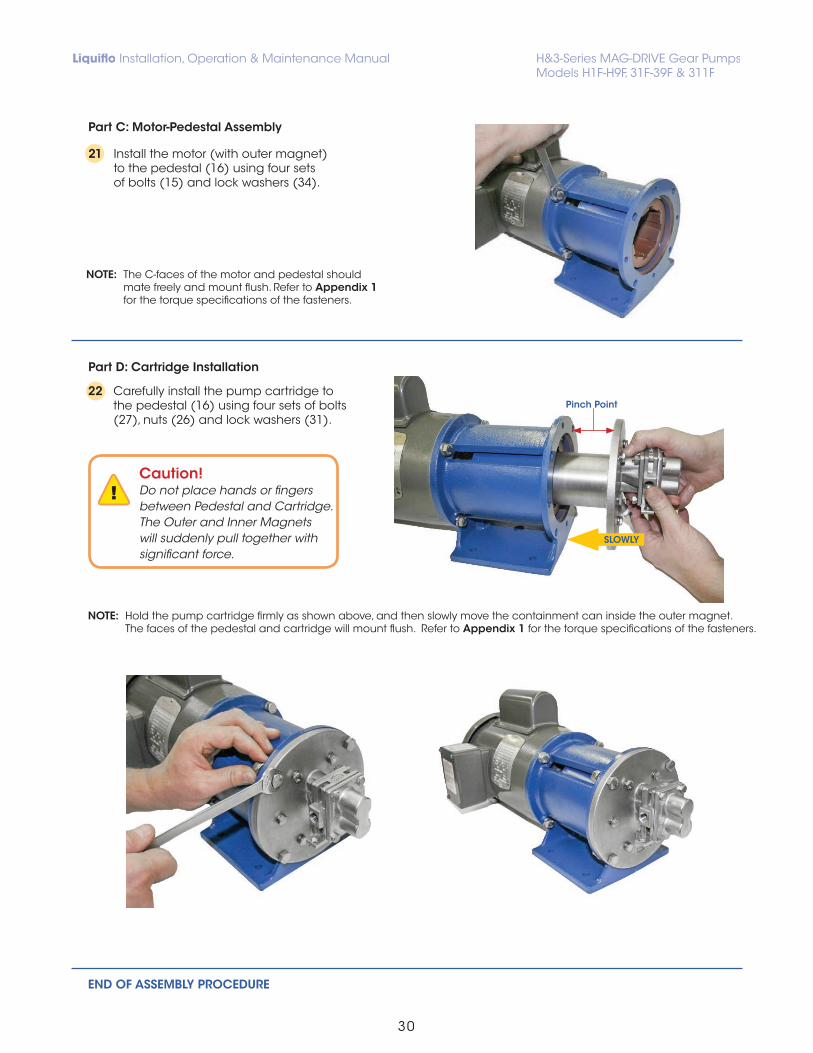
21 Install the motor (with outer magnet) to the pedestal (16) using four sets of bolts (15) and lock washers (34).
22 Carefully install the pump cartridge to the pedestal (16) using four sets of bolts (27), nuts (26) and lock washers (31).
NOTE: Hold the pump cartridge firmly as shown above, and then slowly move the containment can inside the outer magnet. The faces of the pedestal and cartridge will mount flush. Refer to Appendix 1 for the torque specifications of the fasteners.
END OF ASSEMBLY PROCEDURE
Pinch Point
SLOWLY
Caution!Do not place hands or fingers between Pedestal and Cartridge. The Outer and Inner Magnets will suddenly pull together with significant force.
Part C: Motor-Pedestal Assembly
Part D: Cartridge Installation
NOTE: The C-faces of the motor and pedestal should mate freely and mount flush. Refer to Appendix 1 for the torque specifications of the fasteners.
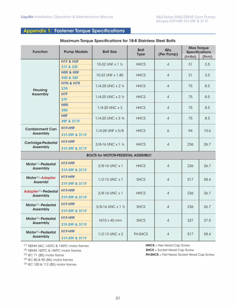
Maximum Torque Specifications for 18-8 Stainless Steel Bolts
Function Pump Models Bolt Size BoltType
Qty.(Per Pump)
Max TorqueSpecifications
(in-lbs) (N-m)
HousingAssembly
H1F & H3F10-32 UNF x 1 ½ HHCS 4 31 3.5
31F & 33FH5R & H5F
10-32 UNF x 1.80 HHCS 4 31 3.535R & 35FH7N & H7R
1/4-20 UNC x 2 ¼ HHCS 4 75 8.537R H7F
1/4-20 UNC x 2 ½ HHCS 4 75 8.537FH9R
1/4-20 UNC x 3 HHCS 4 75 8.539RH9F
1/4-20 UNC x 3 ¾ HHCS 4 75 8.539F & 311F
Containment Can Assembly
H1F-H9F1/4-28 UNF x 5/8 HHCS 6 94 10.6
31F-39F & 311F
Cartridge-Pedestal Assembly
H1F-H9F3/8-16 UNC x 1 ¼ HHCS 4 236 26.7
31F-39F & 311F
BOLTS for MOTOR-PEDESTAL ASSEMBLY:
Motor(1) - Pedestal
AssemblyH1F-H9F
3/8-16 UNC x 1 HHCS 4 236 26.731F-39F & 311F
Motor(2) - Adapter
AssemblH1F-H9F
1/2-13 UNC x 1 SHCS 4 517 58.431F-39F & 311F
Adapter(2) - Pedestal
AssemblyH1F-H9F
3/8-16 UNC x 1 HHCS 4 236 26.731F-39F & 311F
Motor(3) - PedestalAssembly
H1F-H9F3/8-16 UNC x 1 ½ SHCS 4 236 26.7
31F-39F & 311F
Motor(4) - Pedestal
AssemblyH1F-H9F
M10 x 40 mm SHCS 4 327 37.031F-39F & 311F
Motor(5) - Pedestal
AssemblyH1F-H9F
1/2-13 UNC x 2 FH-SHCS 4 517 58.431F-39F & 311F
(1) NEMA 56C, 143TC & 145TC motor frames(2) NEMA 182TC & 184TC motor frames(3) IEC 71 (B5) motor frame(4) IEC 80 & 90 (B5) motor frames (5) IEC 100 & 112 (B5) motor frames
Appendix 1: Fastener Torque Specifications
HHCS = Hex Head Cap ScrewSHCS = Socket Head Cap ScrewFH-SHCS = Flat Head, Socket Head Cap Screw
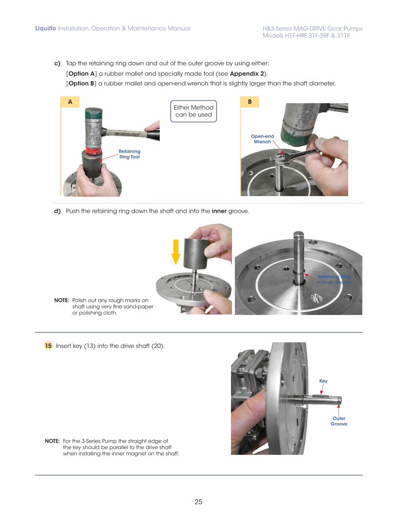
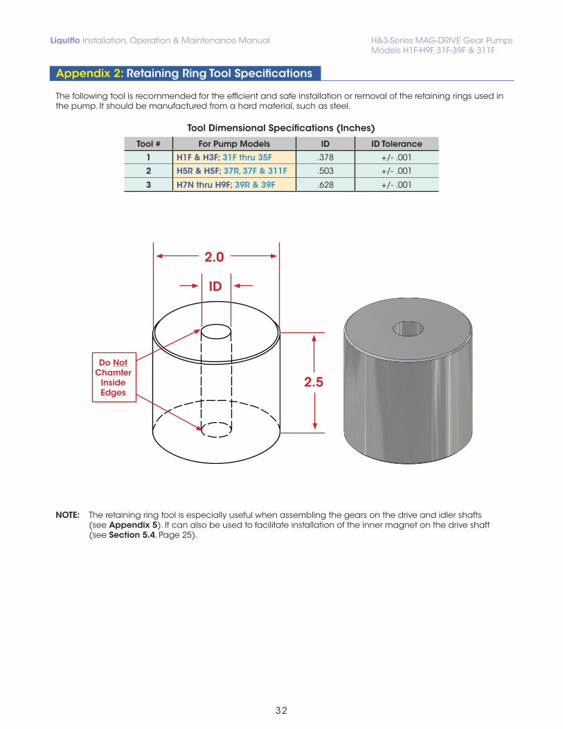
The following tool is recommended for the efficient and safe installation or removal of the retaining rings used in the pump. It should be manufactured from a hard material, such as steel.
NOTE: The retaining ring tool is especially useful when assembling the gears on the drive and idler shafts (see Appendix 5). It can also be used to facilitate installation of the inner magnet on the drive shaft (see Section 5.4, Page 25).
When a pump requires maintenance, a convenient way to restore the pump to like-new condition is to use a repair kit. The repair kit contains all internal wear parts as well as O-rings, retaining rings, bearing lock pins, housing alignment pins and keys.
In some cases, only certain parts may need to be replaced. The primary wear parts of the pump are the gears, shafts, wear plates and bearings. The center housing (secondary wear part) may also incure physical wear by contact with the gears caused by excessively worn bearings. (Note: the center housing is not included in a standard repair kit.) These wear parts can be reused if they are in acceptable condition. O-rings and retaining rings should not be reused. The following used parts should be inspected and evaluated for reuse based on the specifications given in the Wear Allowances Chart (see Page 35).
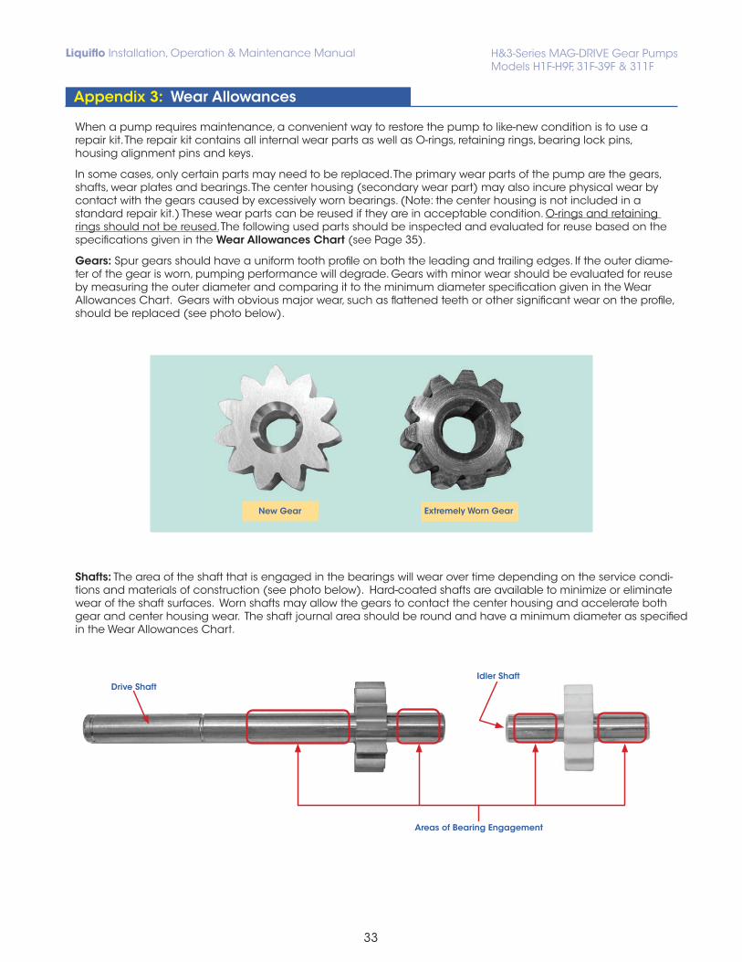
Gears: Spur gears should have a uniform tooth profile on both the leading and trailing edges. If the outer diame-ter of the gear is worn, pumping performance will degrade. Gears with minor wear should be evaluated for reuse by measuring the outer diameter and comparing it to the minimum diameter specification given in the Wear Allowances Chart. Gears with obvious major wear, such as flattened teeth or other significant wear on the profile, should be replaced (see photo below).
Shafts: The area of the shaft that is engaged in the bearings will wear over time depending on the service condi- tions and materials of construction (see photo below). Hard-coated shafts are available to minimize or eliminate wear of the shaft surfaces. Worn shafts may allow the gears to contact the center housing and accelerate both gear and center housing wear. The shaft journal area should be round and have a minimum diameter as specified in the Wear Allowances Chart.
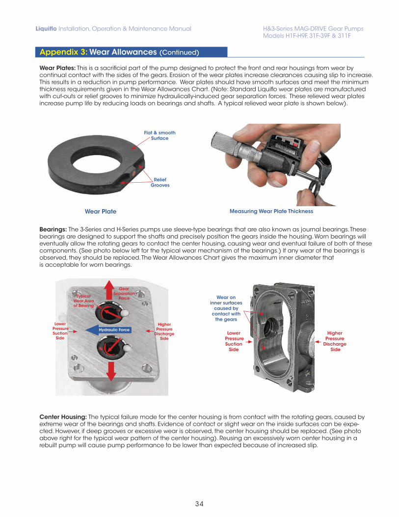
Wear Plates: This is a sacrificial part of the pump designed to protect the front and rear housings from wear by continual contact with the sides of the gears. Erosion of the wear plates increase clearances causing slip to increase. This results in a reduction in pump performance. Wear plates should have smooth surfaces and meet the minimum thickness requirements given in the Wear Allowances Chart. (Note: Standard Liquiflo wear plates are manufactured with cut-outs or relief grooves to minimize hydraulically-induced gear separation forces. These relieved wear plates increase pump life by reducing loads on bearings and shafts. A typical relieved wear plate is shown below).
Bearings: The 3-Series and H-Series pumps use sleeve-type bearings that are also known as journal bearings. These bearings are designed to support the shafts and precisely position the gears inside the housing. Worn bearings will eventually allow the rotating gears to contact the center housing, causing wear and eventual failure of both of these components. (See photo below left for the typical wear mechanism of the bearings.) If any wear of the bearings is observed, they should be replaced. The Wear Allowances Chart gives the maximum inner diameter that is acceptable for worn bearings.
Center Housing: The typical failure mode for the center housing is from contact with the rotating gears, caused by extreme wear of the bearings and shafts. Evidence of contact or slight wear on the inside surfaces can be expe-cted. However, if deep grooves or excessive wear is observed, the center housing should be replaced. (See photo above right for the typical wear pattern of the center housing). Reusing an excessively worn center housing in a rebuilt pump will cause pump performance to be lower than expected because of increased slip.
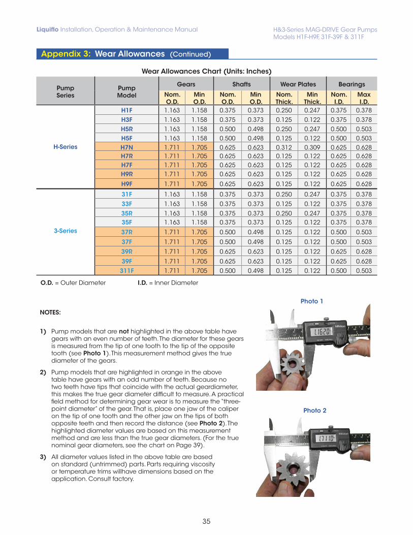
1) Pump models that are not highlighted in the above table have gears with an even number of teeth. The diameter for these gears is measured from the tip of one tooth to the tip of the opposite tooth (see Photo 1). This measurement method gives the true diameter of the gears.
2) Pump models that are highlighted in orange in the above table have gears with an odd number of teeth. Because no two teeth have tips that coincide with the actual geardiameter, this makes the true gear diameter difficult to measure. A practical field method for determining gear wear is to measure the “three- point diameter” of the gear. That is, place one jaw of the caliper on the tip of one tooth and the other jaw on the tips of both opposite teeth and then record the distance (see Photo 2). The highlighted diameter values are based on this measurement method and are less than the true gear diameters. (For the true nominal gear diameters, see the chart on Page 39).
3) All diameter values listed in the above table are based on standard (untrimmed) parts. Parts requiring viscosity or temperature trims willhave dimensions based on the application. Consult factory.
NOTE: For Liquiflo Part Numbers, refer to H-Series or 3-Series Consolidated Bill of Materials (BOM).
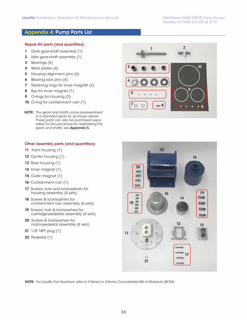
NOTE: The gears and shafts come preassembled in a standard repair kit, as shown above. These parts can also be purchased sepa- rately. For the procedure for assembling the gears and shafts, see Appendix 5.
Other assembly parts (and quantities):
11 Front housing (1)
12 Center housing (1)
13 Rear housing (1)
14 Inner magnet (1)
15 Outer magnet (1)
16 Containment can (1)
17 Screws, nuts and lockwashers for housing assembly (4 sets)
18 Screws & lockwashers for containment can assembly (6 sets)
19 Screws, nuts & lockwashers for cartridge-pedestal assembly (4 sets)
20 Screws & lockwashers for motor-pedestal assembly (4 sets)
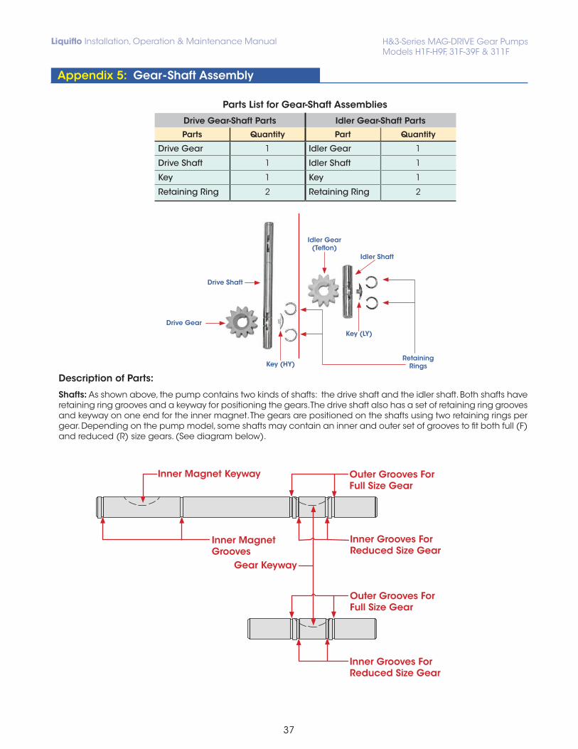
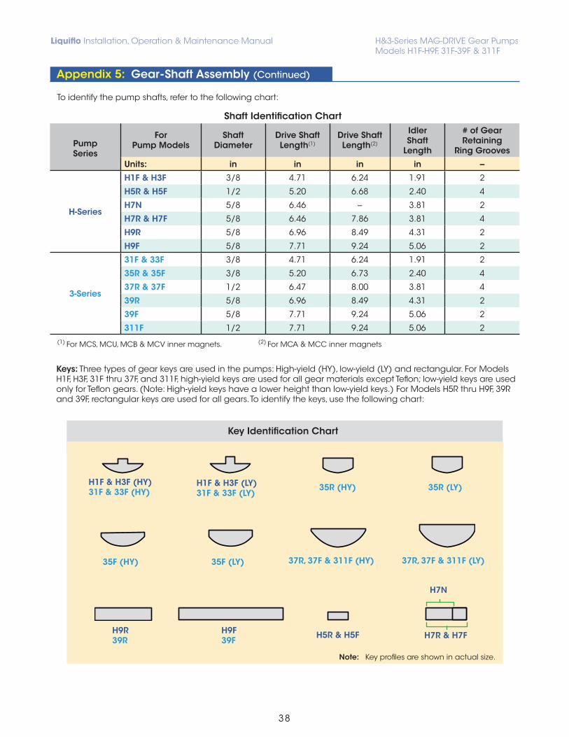
Shafts: As shown above, the pump contains two kinds of shafts: the drive shaft and the idler shaft. Both shafts have retaining ring grooves and a keyway for positioning the gears. The drive shaft also has a set of retaining ring grooves and keyway on one end for the inner magnet. The gears are positioned on the shafts using two retaining rings per gear. Depending on the pump model, some shafts may contain an inner and outer set of grooves to fit both full (F) and reduced (R) size gears. (See diagram below).
Keys: Three types of gear keys are used in the pumps: High-yield (HY), low-yield (LY) and rectangular. For Models H1F, H3F, 31F thru 37F, and 311F, high-yield keys are used for all gear materials except Teflon; low-yield keys are used only for Teflon gears. (Note: High-yield keys have a lower height than low-yield keys.) For Models H5R thru H9F, 39R and 39F, rectangular keys are used for all gears. To identify the keys, use the following chart:
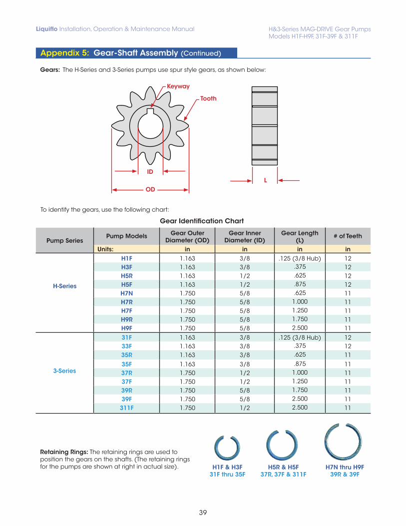
Gears: The H-Series and 3-Series pumps use spur style gears, as shown below:
To identify the gears, use the following chart:
Retaining Rings: The retaining rings are used to position the gears on the shafts. (The retaining rings for the pumps are shown at right in actual size).
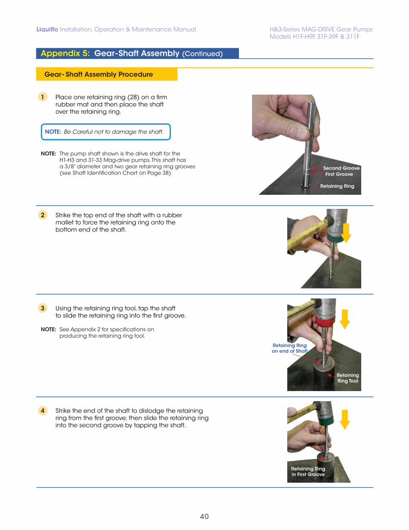
1 Place one retaining ring (28) on a firm rubber mat and then place the shaft over the retaining ring.
NOTE: The pump shaft shown is the drive shaft for the H1-H3 and 31-33 Mag-drive pumps. This shaft has a 3/8” diameter and two gear retaining ring grooves (see Shaft Identification Chart on Page 38).
2 Strike the top end of the shaft with a rubber mallet to force the retaining ring onto the bottom end of the shaft.
3 Using the retaining ring tool, tap the shaft to slide the retaining ring into the first groove. NOTE: See Appendix 2 for specifications on producing the retaining ring tool.
4 Strike the end of the shaft to dislodge the retaining ring from the first groove; then slide the retaining ring into the second groove by tapping the shaft.
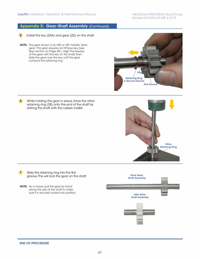
5 Install the key (23A) and gear (22) on the shaft.
NOTE: The gear shown is an H3F or 33F metallic drive gear. This gear requires an HY-type key (see Keys section on Page 38.) Align the keyway of the gear with the key on the shaft; then slide the gear over the key until the gear contacts the retaining ring.
6 While holding the gear in place, force the other retaining ring (28) onto the end of the shaft by striking the shaft with the rubber mallet.
7 Slide the retaining ring into the first groove, This will lock the gear on the shaft.
NOTE: As a check, pull the gear by hand along the axis of the shaft to make sure it is securely locked into position.
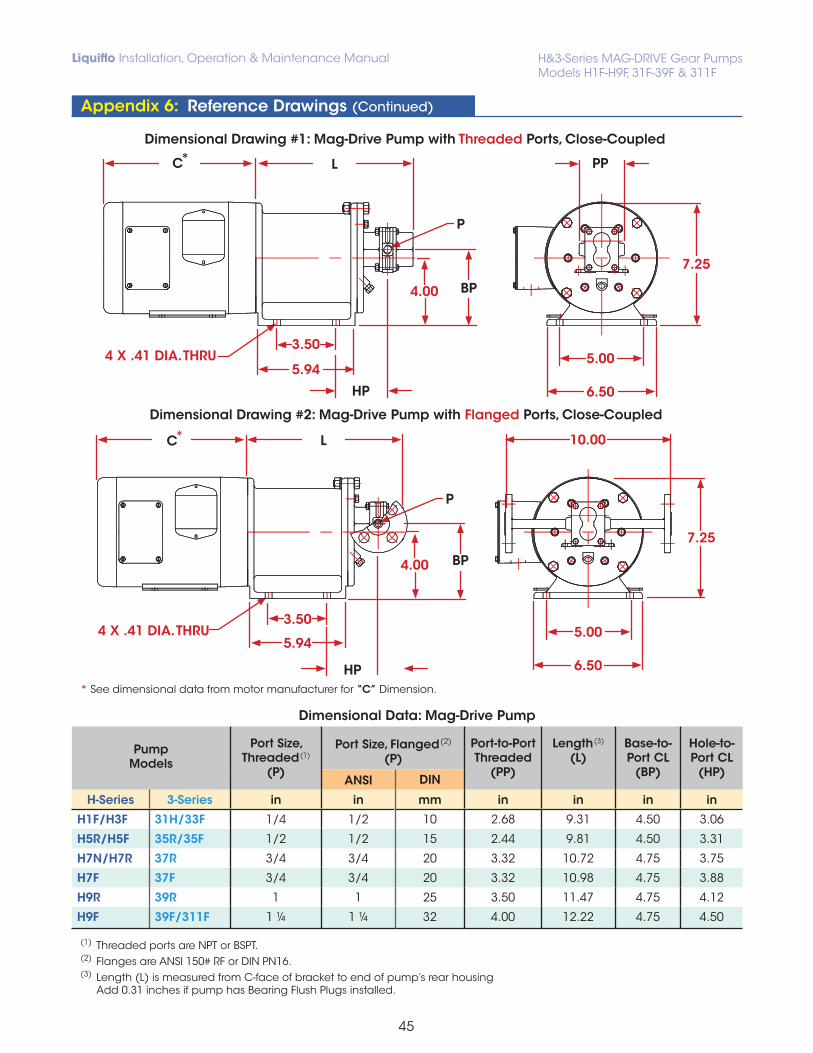
Dimensional Drawing #1: Mag-Drive Pump with Threaded Ports, Close-Coupled
Dimensional Drawing #2: Mag-Drive Pump with Flanged Ports, Close-Coupled
* See dimensional data from motor manufacturer for “C” Dimension.
Dimensional Data: Mag-Drive Pump
PumpModels
Port Size,Threaded
(1)
(P)
Port Size, Flanged
(2)
(P)Port-to-PortThreaded
(PP)
Length (3)
(L)Base-to-Port CL
(BP)
Hole-to-Port CL
(HP)ANSI DIN
H-Series 3-Series in in mm in in in in
H1F/H3F 31H/33F 1/4 1/2 10 2.68 9.31 4.50 3.06
H5R/H5F 35R/35F 1/2 1/2 15 2.44 9.81 4.50 3.31
H7N/H7R 37R 3/4 3/4 20 3.32 10.72 4.75 3.75
H7F 37F 3/4 3/4 20 3.32 10.98 4.75 3.88
H9R 39R 1 1 25 3.50 11.47 4.75 4.12
H9F 39F/311F 1 ¼ 1 ¼ 32 4.00 12.22 4.75 4.50
(1) Threaded ports are NPT or BSPT. (2) Flanges are ANSI 150# RF or DIN PN16.(3) Length (L) is measured from C-face of bracket to end of pump’s rear housing Add 0.31 inches if pump has Bearing Flush Plugs installed.
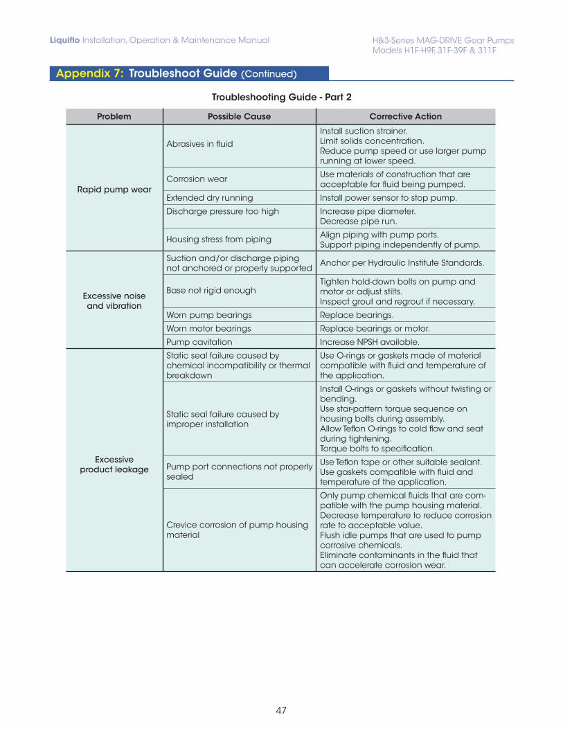
Install suction strainer.Limit solids concentration.Reduce pump speed or use larger pump running at lower speed.
Corrosion wear Use materials of construction that are acceptable for fluid being pumped.
Extended dry running Install power sensor to stop pump.
Discharge pressure too high Increase pipe diameter.Decrease pipe run.
Housing stress from piping Align piping with pump ports.Support piping independently of pump.
Excessive noise and vibration
Suction and/or discharge piping not anchored or properly supported
Anchor per Hydraulic Institute Standards.
Base not rigid enoughTighten hold-down bolts on pump and motor or adjust stilts.Inspect grout and regrout if necessary.
Worn pump bearings Replace bearings.
Worn motor bearings Replace bearings or motor.
Pump cavitation Increase NPSH available.
Excessive product leakage
Static seal failure caused by chemical incompatibility or thermal breakdown
Use O-rings or gaskets made of material compatible with fluid and temperature of the application.
Static seal failure caused by improper installation
Install O-rings or gaskets without twisting or bending.Use star-pattern torque sequence on housing bolts during assembly.Allow Teflon O-rings to cold flow and seat during tightening.Torque bolts to specification.
Pump port connections not properly sealed
Use Teflon tape or other suitable sealant.Use gaskets compatible with fluid and temperature of the application.
Crevice corrosion of pump housing material
Only pump chemical fluids that are com-patible with the pump housing material.Decrease temperature to reduce corrosion rate to acceptable value.Flush idle pumps that are used to pump corrosive chemicals.Eliminate contaminants in the fluid that can accelerate corrosion wear.