Installation of Hydraulic Control Arm for HiQual XL Hydraulic Chute HiQual Livestock Equipment (844) 544-7825 www.HiQualEquipment.com Scan this QR code with your smart phone to visit our website. www.hiqualequipment.com
Transcript
Installation of Hydraulic
Control Arm for
HiQual XL Hydraulic Chute
HiQual Livestock Equipment
(844) 544-7825 www.HiQualEquipment.com
Scan this QR code with your
smart phone to visit our website. www.hiqualequipment.com
2
NEW PRODUCT WARRANTY
HIQUAL L IVESTOCK EQUIPMENT LIMITED WARRANTY FOR NEW HIQUAL COMPANY PRODUCTS
A. GENERAL PROVISIONS . “HiQual” means HiQual Company, 200 N. Cleveland, Lennox, SD 57039. The warranties described below are provided by HiQual to the original purchasers of new products purchased from HiQual or from an authorized HiQual Dealer (the “Products”). Under these warranties, HiQual will, at its option, repair or replace at its factory any Product covered under these warranties which is found to be defective in material and workmanship during the applicable warranty term or refund the purchase price paid for the defective Product. Customer will be responsible for labor charges for removing the defective Product and reinstalling the repaired or replacement Product, any premium charge for overtime labor requested of HiQual and shipping charges to and from HiQual’s factory. These warranties are not transferrable.
B. WARRANTY PERIOD . Subject to exclusions and limitations set forth herein, each new Product is warranted for the number of years specified below. Each warranty term begins from the date of purchase regardless of delay in receipt of the Product by Customer due to the time required to process, handle, ship, assemble, construct and install the Product. Customer must retain proof of the date of purchase. Replacement parts for and repairs to the Product will be warranted only for the remainder of the original warranty term. The replacement parts for or repairs to the Product will not extend the warranty term beyond the original warranty term. Products described below include all parts, components and accessories.
PRODUCTS All Steel products 1 Year All Poly Products 3 years Flex Connectors 5 Years C. ITEMS COVERED SEPARATELY . The HiQual warranties do not cover any parts, components or materials that are part of the Product, or used in conjunction with the Product, that are not manufactured by Sioux Steel. Such parts, components and materials will be subject to the warranties provided by the manufacturer, if any. D. WHAT IS NOT WARRANTED . HiQual does not warrant and is not responsible for the following: (1) used products; (2) modification or alteration of the Products; (3) Products that have not been properly installed or not installed in accordance with the instruction manual, improper assembly, or improper construction by any persons other than HiQual employees; (4) depreciation, damage or loss caused by the use of parts, components or accessories not provided by HiQual, unauthorized repairs, normal wear, lack of necessary and proper maintenance, a failure to follow operating instructions/recommendations, misuse, lack of proper protection during storage, vandalism or theft, exposure to the elements or corrosive materials, accidents or acts of nature including lightning, flooding, hail, straight winds and tornadoes; and (5) cosmetic damage or damage that does not hinder the functionality of the Products. E. LIMITATIONS OF WARRANTIES AND CUSTOMER’S REMEDIES. To the extent permitted by law, neither HiQual, the Dealer nor any person or company affiliated with either of them makes any warranties, representations, conditions or promises express or implied as to the quality, performance or freedom from defects of the Products covered by these warranties other than those set forth herein. THERE ARE NO IMPLIED WARRANTIES OF MERCHANTABILITY OR FITNESS FOR A PARTICULAR PURPOSE. NEITHER HIQUAL, THE DEALER, NOR ANY PERSON OR COMPANY AFFILIATED WITH EITHER OF THEM WILL BE LIABLE FOR ANY DAMAGES, INCLUDING, BUT NOT LIMITED TO, INCIDENTAL, SPECIAL, EXEMPLARY, CONSEQUENTIAL, LOST PROFITS AND REVENUES, LOST USE OF THE PRODUCTS OR ANY OTHER PROPERTY, BODILY INJURY OR PROPERTY DAMAGE CLAIMS OF ANY PERSON, LOST COMMODITIES, REMOVAL OR STORAGE COSTS FOR THE PRODUCTS, OTHER EQUIPMENT AND COMMODITIES, DAMAGE TO THE ENVIRONMENT ARISING FROM OR IN ANY MANNER RELATED TO ANY RELEASE OF HAZARDOUS MATERIALS, AND REMEDIATION EXPENSES THEREFORE, WHETHER BASED ON CONTRACT, TORT, STRICT LIABILITY OR ANY OTHER LEGAL BASIS, EVEN IF ADVISED OF THE POSSIBILITY OF SUCH DAMAGES. IN NO INSTANCE WILL SIOUX STEEL, THE DEALER OR ANY PERSON OR COMPANY AFFILIATED WITH EITHER OF THEM BE LIABLE TO CUSTOMER OR ANY PERSON IN AN AMOUNT IN EXCESS OF THE PURCHASE PRICE PAID BY CUSTOMER FOR THE PRODUCT. F. NO DEALER WARRANTY . THE DEALER HAS NO AUTHORITY TO MAKE ANY WARRANTY, REPRESENTATION, CONDITION OR PROMISE ON BEHALF OF HIQUAL, OR TO MODIFY THE TERMS OR LIMITATIONS OF THIS WARRANTY IN ANY WAY. G. GOVERNING LAW/VENUE . These warranties, and all terms set forth herein, are governed by the laws of the State of South Dakota and, where applicable, the laws of the United States of America. Any and all disputes arising from these warranties, the purchase and use of the Products, bodily injury and property damage claims or otherwise must be venued in the South Dakota Circuit Court sitting in Minnehaha County, South Dakota. Customer agrees to such venue and waives any challenge to such court’s jurisdiction based upon lack of personal jurisdiction or inconvenience. H. SECURING WARRANTY SERVICE. In order to receive warranty services, customer must give HiQual written notice of a warranty claim within 30 days of the date of discovery of the defective materials or workmanship, and customer must complete the following steps. (1) Obtain from HiQual a Return Materials Authorization Number (“RMA Number”) by calling the Customer Service at 1 -800-557-4689 and providing the following information.
� An explanation as to why the products being returned.
� The name of the territory representative, dealer or HiQual sales person from whom the product was purchased.
� The dealers ID number / account number.
� The invoice number and date of purchase.
� Customers name, phone number and address.
� The date the product will be returned.
(2) Pay the shipping charges to and from the HIQual’s factory.
(3) Ship the product to HiQual, 200 N. Cleveland, Lennox, SD 57039
{00659155.1}
3
4
TABLE OF CONTENTS
SECTION DESCRIPTION PAGE HIQUAL WARRANTY 2
TABLE OF CONTENTS 4
1
1.1
1.2
1.3
1.4
1.5
1.6
1.7
1.8
INSTALLATION
Intro
Uninstallation of Control Mount and Hoses
Hydraulic Arm Components and Hardware
Setting the Base Tube
Preparing and Setting the Top Beam
Setting the Control Arm
Hose Extension Kit Installation
Grease Zerks
5
5
5
6
6
7
7
8
8
2 USAGE 9
2.1 Hydraulic Control Levers 9
2.2 Pressure Setting 9
2.3 Break-In 9
2.4
2.5
Hydraulic Control Arm
Pre-Start Checklist
10
11 2.6 STORAGE 12
2.6A Grease 12 2.6B Oil 12
2.6C Paint 12
3 SERVICE AND MAINTENANCE 13
3.1 Lubricants 13
3.2 Greasing 13
5
1. INSTALLATION
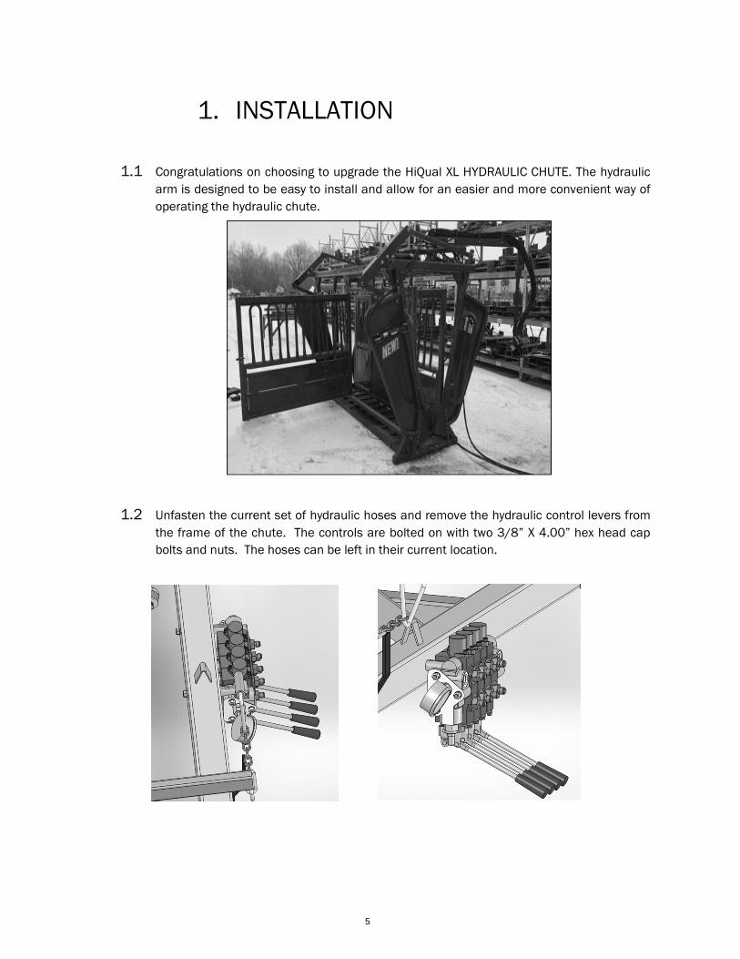
1.1 Congratulations on choosing to upgrade the HiQual XL HYDRAULIC CHUTE. The hydraulic
arm is designed to be easy to install and allow for an easier and more convenient way of
operating the hydraulic chute.
1.2 Unfasten the current set of hydraulic hoses and remove the hydraulic control levers from
the frame of the chute. The controls are bolted on with two 3/8” X 4.00” hex head cap
bolts and nuts. The hoses can be left in their current location.
6
Hose Brackets
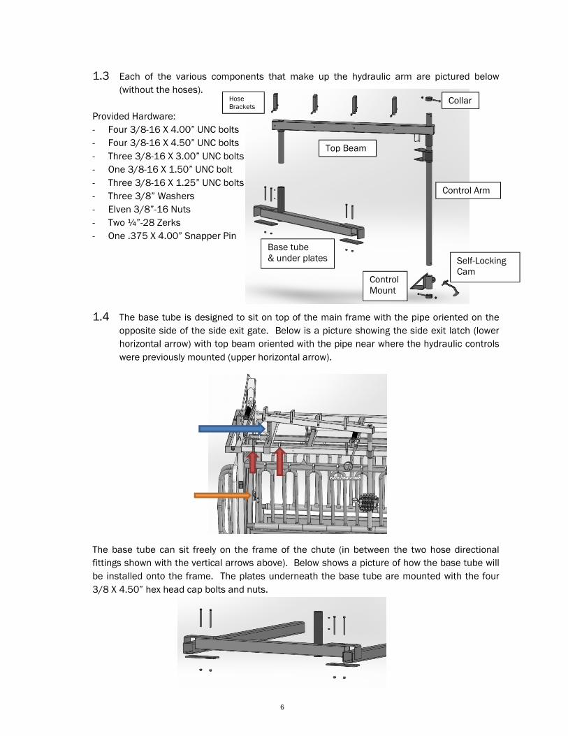
1.3 Each of the various components that make up the hydraulic arm are pictured below
(without the hoses).
Provided Hardware:
- Four 3/8-16 X 4.00” UNC bolts
- Four 3/8-16 X 4.50” UNC bolts
- Three 3/8-16 X 3.00” UNC bolts
- One 3/8-16 X 1.50” UNC bolt
- Three 3/8-16 X 1.25” UNC bolts
- Three 3/8” Washers
- Elven 3/8”-16 Nuts
- Two ¼”-28 Zerks
- One .375 X 4.00” Snapper Pin
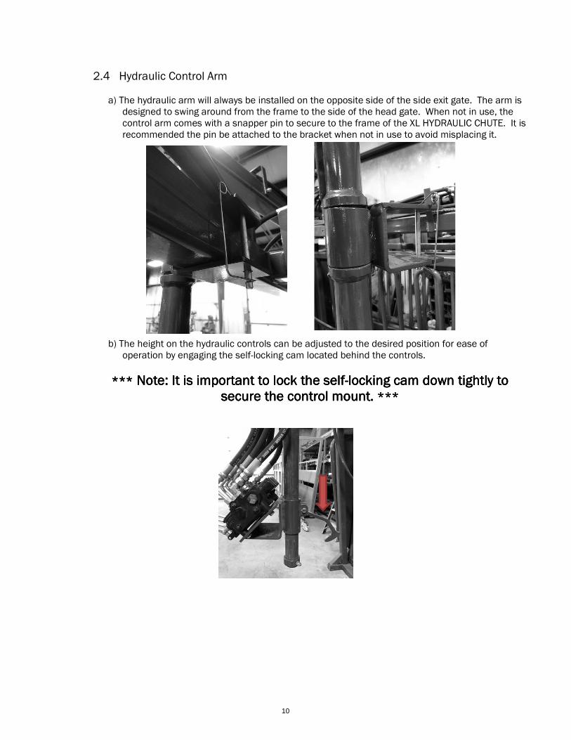
1.4 The base tube is designed to sit on top of the main frame with the pipe oriented on the
opposite side of the side exit gate. Below is a picture showing the side exit latch (lower
horizontal arrow) with top beam oriented with the pipe near where the hydraulic controls
were previously mounted (upper horizontal arrow).
The base tube can sit freely on the frame of the chute (in between the two hose directional
fittings shown with the vertical arrows above). Below shows a picture of how the base tube will
be installed onto the frame. The plates underneath the base tube are mounted with the four
3/8 X 4.50” hex head cap bolts and nuts.
Base tube & under plates
Top Beam
Collar
Control Arm
Control Mount
Self-Locking Cam
7
1.5 Install the hose brackets (4x) utilizing 3/8 X 4.00” hex head cap bolts and nuts onto the
top beam. After the hose brackets are installed, install the top beam by inserting the pipe
from the top beam inside the pipe on the base tube. See picture below.
The control arm should be inserted into the top beam from the underside and secured
with the 3/8 X 3.00” UNC bolt, nut and collar provided. See picture below.
1.6 The control mount can now be inserted onto the control arm and secured by adding the
bottom collar with the 3/8 X 3.00” UNC bolt, nut and collar provided (same as the top
collar). The locking cam can be installed to secure the control mount at the desired
height using the 3/8 X 1.50” UNC bolt and nut. See picture below.
***Note: It is important to lock the self-locking cam down tightly to secure the control mount. ***
8
The hydraulic controls can now be reinstalled onto the control mount utilizing (3x) 3/8” X 1.25”
HHC bolts and washers from the backside of the controls mount.
1.7 Included in the hydraulic arm kit is a box of hose extensions. Each of these hoses was
designed to be 11 ft. long to cover the length of the hydraulic arm with two larger
diameter hoses for the supply and return lines. To install, connect each hose to the
hydraulic controls and run each hose through the hose brackets connecting to the other
end of the existing hoses. Some adjustment may be necessary to keep the hydraulic
hoses in a neutral position.
1.8 Install the two zerks on the base tube pipe and add lubricant. The Hydraulic Control Arm
should swing smoothly and with minimal restriction.
9
2. USAGE 2.1 HYDRAULIC CONTROL LEVERS
Front control lever – controls the neck extender (up to open, down
to close).
2nd control lever – controls the headgate (up to open, down to
close).
3rd control lever – controls the squeeze (up to release, down to
squeeze).
4th Rear control lever – controls the tailgate (up to open, down to
close).
2.2 PRESSURE SETTING
The pressure relief valve is factory set to 1000 PSI. At this point, the valve
opens and the oil is allowed to flow through the system. The 1000 PSI is
the hydraulic pressure and NOT the pressure on the animal, which is much
less. If it is necessary to adjust the setting, remove the acorn nut at the
bottom of the valve unit on the end of the valve bank. With the hydraulic
pump running, operate one of the valves (preferably operating a cylinder to
stroke out). If using a HiQual Hydraulic Power Unit, it will be necessary to
hold the valve open approximately ten to fifteen seconds before full
system pressure is reached due to the two stage pump system. With the
valve still engaged, turn the adjusting screw clockwise to increase
pressure, or counter clockwise to decrease pressure. Be sure not to back
off the adjusting screw too much or it will fall out of the valve body.
2.3 BREAK-IN
Although there are no restrictions on the XL HYDRAULIC CHUTE when using it for the first time,
the following functional items should be checked:
a) Check that all hydraulic hoses are properly secured
b) All hydraulic controls are functioning properly
c) The adjustable side mechanism adjusts smoothly
d) The drop boards are working properly
e) The access doors are closed and latched
f) The headgate and tailgate open and close smoothly
g) All drop tubes are closed and secured
10
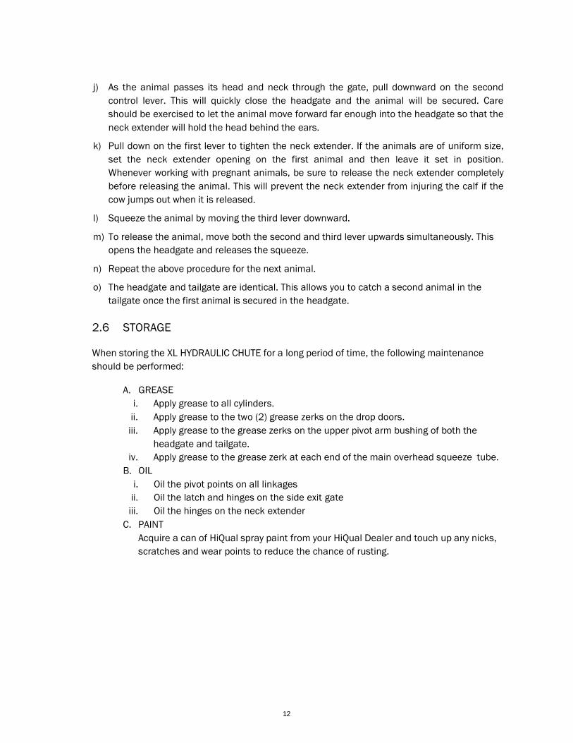
2.4 Hydraulic Control Arm
a) The hydraulic arm will always be installed on the opposite side of the side exit gate. The arm is
designed to swing around from the frame to the side of the head gate. When not in use, the control arm comes with a snapper pin to secure to the frame of the XL HYDRAULIC CHUTE. It is recommended the pin be attached to the bracket when not in use to avoid misplacing it.
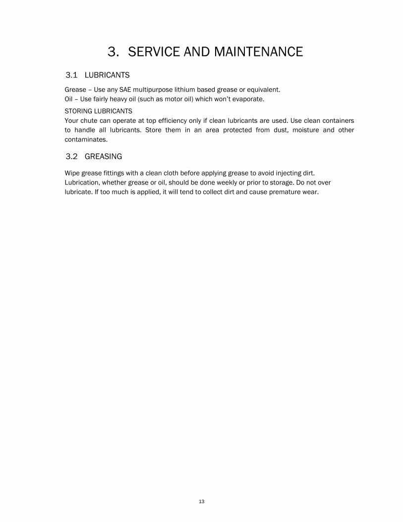
b) The height on the hydraulic controls can be adjusted to the desired position for ease of operation by engaging the self-locking cam located behind the controls.
************ Note: It is important to lock the selfNote: It is important to lock the selfNote: It is important to lock the selfNote: It is important to lock the self----locking cam down tightly to locking cam down tightly to locking cam down tightly to locking cam down tightly to secure the control mount. secure the control mount. secure the control mount. secure the control mount. ************
11
2.5 PRE-START CHECKLIST
Efficient and safe operation of the XL HYDRAULIC CHUTE requires that each user read and
understand the usage recommendations and all safety related items.
A pre-start checklist is provided for the user. It is important for both personal safety and
maintaining the good mechanical condition of this unit, that this checklist be followed prior to
placing any livestock in the XL HYDRAULIC CHUTE.
a) Determine which hydraulic power option will be used.
b) Connect hydraulic hoses to hydraulic pump or tractor.
c) Start oil flow by starting the electric or gas motor and moving the control valve in the proper
direction. (A tractor running at idle should give adequate oil flow for proper operation of the
chute.)
d) Move the four (4) control valves to determine if they are working properly. Moving the
handle down should make them close.
e) Check the side exit gate. Make sure that it is closed and locked securely. Keep the locking
mechanism closed on the side exit gate.
f) Set the width of the squeeze chute to correspond with the size of the animal to be
processed. To change the width of the squeeze chute, make sure the squeeze chute is
empty. Squeeze the chute to the narrowest position by pushing the 3rd lever (squeeze
control) up, until the side is closed to the max. Put gentle pressure against the bottom of the
side with your foot to keep the bottom of the side from moving outward. Slowly apply
pressure upward on the 3rd hydraulic lever while applying pressure at the bottom of the side
with your foot. Continue to apply upward pressure on the hydraulic lever until the side of the
hydraulic squeeze chute is as high as it can go. When the side of the squeeze chute is in the
“up” position, move the bottom of the side with your foot to place the width at the desired
position for the size of cattle that you will process. There are tabs on the teeth at the bottom
of the side you are adjusting. These teeth will help ensure that the side cannot be lifted
when there is pressure from an animal inside the XL HYDRAULIC CHUTE. For this reason, you
need to apply pressure to the side when you are adjusting the side of the hydraulic squeeze
chute.
g) Open the headgate 12 to 15 inches so that the animal can enter the headgate, but cannot
get its shoulders through.
h) Use the front hydraulic control lever to set the opening of the neck extender. It is
recommended to keep the neck extender extra wide for the first animal.
i) As the animals enter, close the tailgate by pulling downward on the rear control lever.
12
j) As the animal passes its head and neck through the gate, pull downward on the second
control lever. This will quickly close the headgate and the animal will be secured. Care
should be exercised to let the animal move forward far enough into the headgate so that the
neck extender will hold the head behind the ears.
k) Pull down on the first lever to tighten the neck extender. If the animals are of uniform size,
set the neck extender opening on the first animal and then leave it set in position.
Whenever working with pregnant animals, be sure to release the neck extender completely
before releasing the animal. This will prevent the neck extender from injuring the calf if the
cow jumps out when it is released.
l) Squeeze the animal by moving the third lever downward.
m) To release the animal, move both the second and third lever upwards simultaneously. This
opens the headgate and releases the squeeze.
n) Repeat the above procedure for the next animal.
o) The headgate and tailgate are identical. This allows you to catch a second animal in the
tailgate once the first animal is secured in the headgate.
2.6 STORAGE
When storing the XL HYDRAULIC CHUTE for a long period of time, the following maintenance
should be performed:
A. GREASE
i. Apply grease to all cylinders.
ii. Apply grease to the two (2) grease zerks on the drop doors.
iii. Apply grease to the grease zerks on the upper pivot arm bushing of both the
headgate and tailgate.
iv. Apply grease to the grease zerk at each end of the main overhead squeeze tube.
B. OIL
i. Oil the pivot points on all linkages
ii. Oil the latch and hinges on the side exit gate
iii. Oil the hinges on the neck extender
C. PAINT
Acquire a can of HiQual spray paint from your HiQual Dealer and touch up any nicks,
scratches and wear points to reduce the chance of rusting.
13
3. SERVICE AND MAINTENANCE
3.1 LUBRICANTS
Grease – Use any SAE multipurpose lithium based grease or equivalent.
Oil – Use fairly heavy oil (such as motor oil) which won’t evaporate.
STORING LUBRICANTS
Your chute can operate at top efficiency only if clean lubricants are used. Use clean containers
to handle all lubricants. Store them in an area protected from dust, moisture and other
contaminates.
3.2 GREASING
Wipe grease fittings with a clean cloth before applying grease to avoid injecting dirt.
Lubrication, whether grease or oil, should be done weekly or prior to storage. Do not over
lubricate. If too much is applied, it will tend to collect dirt and cause premature wear.
14
HiQual Livestock Equipment
PO Box 1265
Sioux Falls, SD 57101-1265
Phone 844-5HI-QUAL
(844-544-7825)
www.hiqualequipment.com
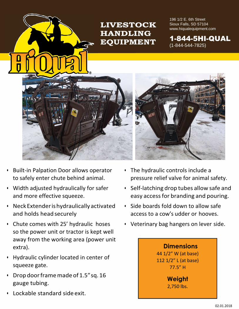
LIVESTOCK
HANDLING
EQUIPMENT
196 1/2 E. 6th Street Sioux Falls, SD 57104 www.hiqualequipment.com