590+ Series DC Digital Drive Product Manual HA466461U003 Issue 4 Copyright 2004 SSD Drives Limited (formerly Eurotherm Drives Limited) All rights strictly reserved. No part of this document may be stored in a retrieval system, or transmitted in any form or by any means to persons not employed by an SSD Drives company without written permission from SSD Drives Ltd. Although every effort has been taken to ensure the accuracy of this document it may be necessary, without notice, to make amendments or correct omissions. SSD Drives cannot accept responsibility for damage, injury, or expenses resulting therefrom. Compatible with Version 7.x Software
All rights strictly reserved. No part of this document may be stored in a retrieval system, or transmitted in any form or byany means to persons not employed by an SSD Drives company without written permission from SSD Drives Ltd.
Although every effort has been taken to ensure the accuracy of this document it may be necessary, without notice, tomake amendments or correct omissions. SSD Drives cannot accept responsibility for damage, injury, or expensesresulting therefrom.
Compatible with Version 7.x Software
Cont.2
WARRANTYSSD Drives warrants the goods against defects in design, materials and workmanship
for the period of 12 months from the date of delivery on the termsdetailed in SSD Drives Standard Conditions of Sale IA058393C.
SSD Drives reserves the right to change the content and product specification without notice.
Cont.3
RequirementsIMPORTANT: Please read this information BEFORE installing the equipment.
Intended UsersThis manual is to be made available to all persons who are required to install, configure orservice equipment described herein, or any other associated operation.
The information given is intended to highlight safety issues, and to enable the user to obtainmaximum benefit from the equipment.
Complete the following table for future reference detailing how the unit is to be installed andused.
INSTALLATION DETAILS
Serial Number(see product label)
Where installed(for your owninformation)
Unit used as a:(refer to Certificationfor the Converter)
Component Relevant Apparatus
Unit fitted: Wall-mounted Enclosure
Application AreaThe equipment described is intended for industrial (non consumer) motor speed control utilisingdc shunt machines.
PersonnelInstallation, operation and maintenance of the equipment should be carried out by qualifiedpersonnel. A qualified person is someone who is technically competent and familiar with allsafety information and established safety practices; with the installation process, operation andmaintenance of this equipment; and with all the hazards involved.
!Safety Information
Cont.4
Hazards
WARNING! This equipment can endanger life through rotating machinery and high voltages.
Failure to observe the following will constitute an ELECTRICAL SHOCK HAZARD.This is a product of the restricted sales distribution class according to IEC 61800-3.In a domestic environment this product may cause radio interference in which case
the user may be required to take adequate measures.This product is designated as “professional equipment” as defined in EN61000-3-2.
Permission of the supply authority shall be obtained before connection to the lowvoltage supply.
• The equipment must be permanently earthed due to the high earth leakage current.• The drive motor must be connected to an appropriate safety earth.• Before working on the equipment, ensure isolation of the mains supply from terminals L1,
L2 and L3.• Never perform high voltage resistance checks on the wiring without first disconnecting the
drive from the circuit being tested.• When replacing a drive in an application and before returning to use, it is essential that all
user defined parameters for the product’s operation are correctly installed.• This equipment contains electrostatic discharge (ESD) sensitive parts. Observe static
control precautions when handling, installing and servicing this product.IMPORTANT: Metal parts may reach a temperature of 90 degrees centigrade in operation.
Application RiskThe specifications, processes and circuitry described herein are for guidance only and may needto be adapted to the user’s specific application.
SSD Drives does not guarantee the suitability of the equipment described in this Manual forindividual applications.
Risk AssessmentUnder fault conditions, power loss or other operating conditions not intended, the equipmentmay not operate as specified. In particular:
• The motor speed may not be controlled• The direction of rotation of the motor may not be controlled• The motor may be energised
Guards The user must provide guarding and /or additional safety systems to prevent risk of injury andelectric shock.
Protective Insulation• All control and signal terminals are SELV, i.e. protected by double insulation. Ensure all
wiring is rated for the highest system voltage.
Note: Thermal sensors contained within the motor must be double insulated.
• All exposed metalwork in the Converter is protected by basic insulation and bonding to asafety earth.
RCDs These are not recommended for use with this product but ,where their use is mandatory, onlyType B RCDs should be used.
!Safety Information
Contents
Contents Page
Cont.5
Chapter 1 GETTING STARTED
Equipment Inspection and Storage ..............................................................1-2Packaging and Lifting Details ......................................................................1-2About this Manual ........................................................................................1-2Initial Steps .............................................................................................................1-2How the Manual is Organised .................................................................................1-3
Chapter 2 AN OVERVIEW OF THE CONVERTER
How it Works.................................................................................................2-1Control Features ...........................................................................................2-2Understanding the Product Code .................................................................2-3Model Number (Europe) ..........................................................................................2-3Catalog Number (North America) ............................................................................2-4
• Door Assembly Product Code ................................................................2-5Product Identification ...................................................................................2-5Component Identification .............................................................................2-6
Unpacking the Converter.........................................................................................3-1Lifting the Converter ................................................................................................3-1Product Dimensions.................................................................................................3-2Mounting the Converter...........................................................................................3-3
• Recommended Tools.............................................................................3-3Ventilation and Cooling Requirements......................................................................3-3
• Installing the Fan (Frame H) ..................................................................3-3• Installing the External Vent Kit (Frames 4 & 5).........................................3-4
AC Line Choke........................................................................................................3-5Filtering ..................................................................................................................3-5Frame H Additional Information...............................................................................3-6
• Removing the Cover (Frame H).............................................................3-6• Changing DC Output Terminals (Frame H) ............................................3-6
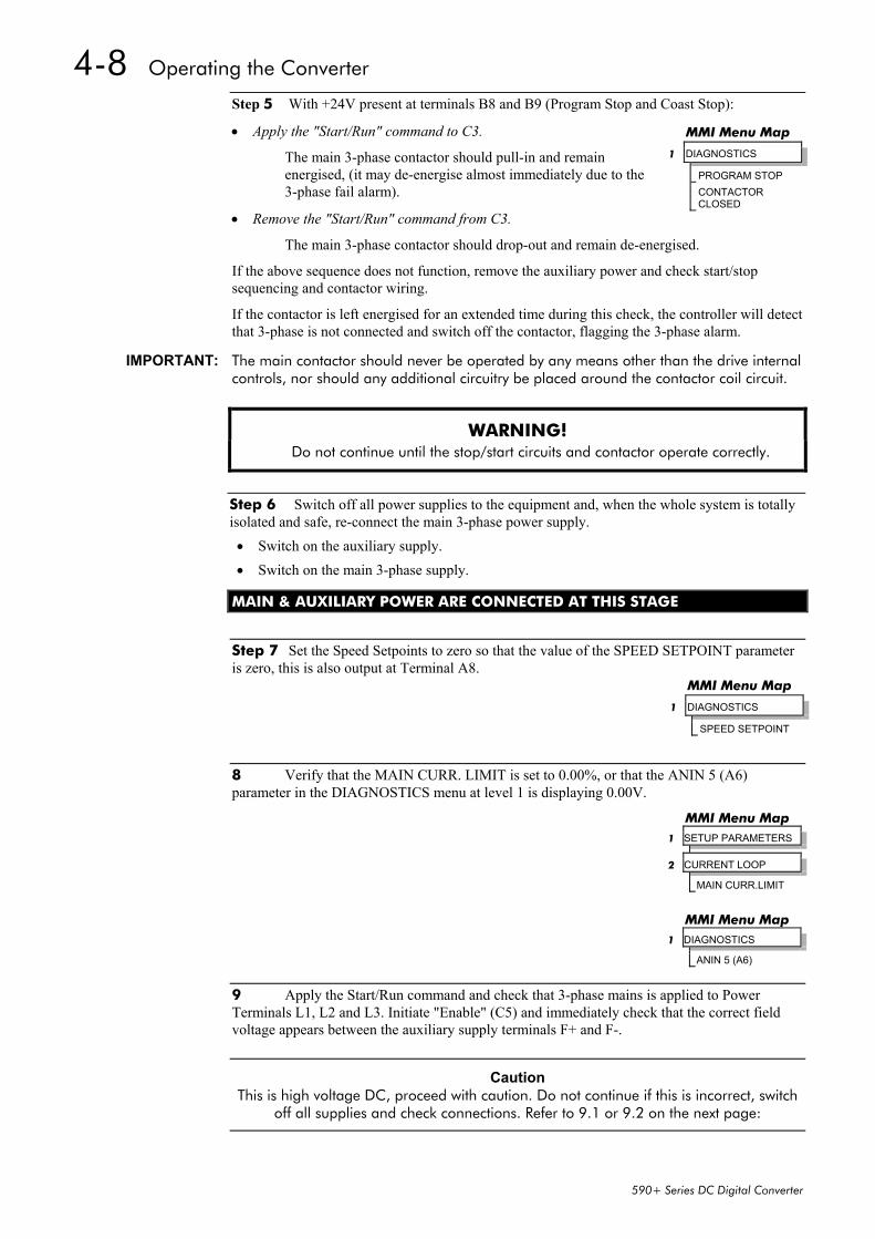
Pre-Operation Checks ..................................................................................4-1Control Philosophy........................................................................................4-2Start/Stop and Speed Control.......................................................................4-2
• Selecting Local or Remote Control .........................................................4-3Reading the Status LEDs ..........................................................................................4-3Setting-up the Converter ..............................................................................4-4Calibrating the Control Board..................................................................................4-4Selecting Speed Feedback .......................................................................................4-5
• Current Loop - The Autotune Feature ...................................................4-13• Speed Loop ........................................................................................4-13
Starting and Stopping Methods .................................................................4-15Stopping Methods .................................................................................................4-15
• Normal Stop (C3) ...............................................................................4-16• Program Stop (B8) ..............................................................................4-18• Coast Stop (B9)...................................................................................4-19• Standstill ............................................................................................4-19• The Trip Condition..............................................................................4-19
Normal Starting Method........................................................................................4-20Advanced Starting Methods ...................................................................................4-20
• Starting Several Converters Simultaneously ..........................................4-20• Jog ....................................................................................................4-20• Crawl.................................................................................................4-20
Contents
Contents Page
Cont.7
Chapter 5 THE OPERATOR STATION
Connecting the Operator Station .................................................................5-1Controlling the Operator Station..................................................................5-1Control Key Definitions............................................................................................5-2
• Keys for Programming the Converter .....................................................5-2• Keys for Operating the Converter Locally ...............................................5-2
Indications ..............................................................................................................5-3• Operator Station LEDs ..........................................................................5-3• Operator Station Alarm Messages .........................................................5-3
The Menu System..........................................................................................5-4The Local Menu ......................................................................................................5-5
• The L/R Key ..........................................................................................5-5• The PROG Key......................................................................................5-5
Navigating the Menu System....................................................................................5-6Changing a Parameter Value...................................................................................5-6The Menu System Map ............................................................................................5-7Menu Shortcuts and Special Key Combinations.........................................................5-8
• Quick Tag Information..........................................................................5-8• Changing the Stack Size (3-button reset) ................................................5-8• Resetting to Factory Defaults (2-button reset) ..........................................5-9
Special Menu Features ...............................................................................5-10Selecting a Menu Viewing Level .............................................................................5-10Selecting the Display Language..............................................................................5-10Password Protection ..............................................................................................5-11
• To Activate Password Protection ...........................................................5-11• To Deactivate Password Protection.......................................................5-12
How to Save, Restore and Copy your Settings............................................5-13Saving Your Application ........................................................................................5-13Restoring Saved Settings ........................................................................................5-13Copying an Application .........................................................................................5-13
Chapter 6 PROGRAMMING YOUR APPLICATION
Programming with Block Diagrams .............................................................6-1Modifying a Block Diagram .....................................................................................6-1
• Setup and Configuration Modes ............................................................6-1• Making and Breaking Function Block Connections..................................6-1• Programming Rules ..............................................................................6-2• Saving Your Modifications .....................................................................6-2
Understanding the Function Block Description ..........................................................6-2• MMI Menu Maps ..................................................................................6-3
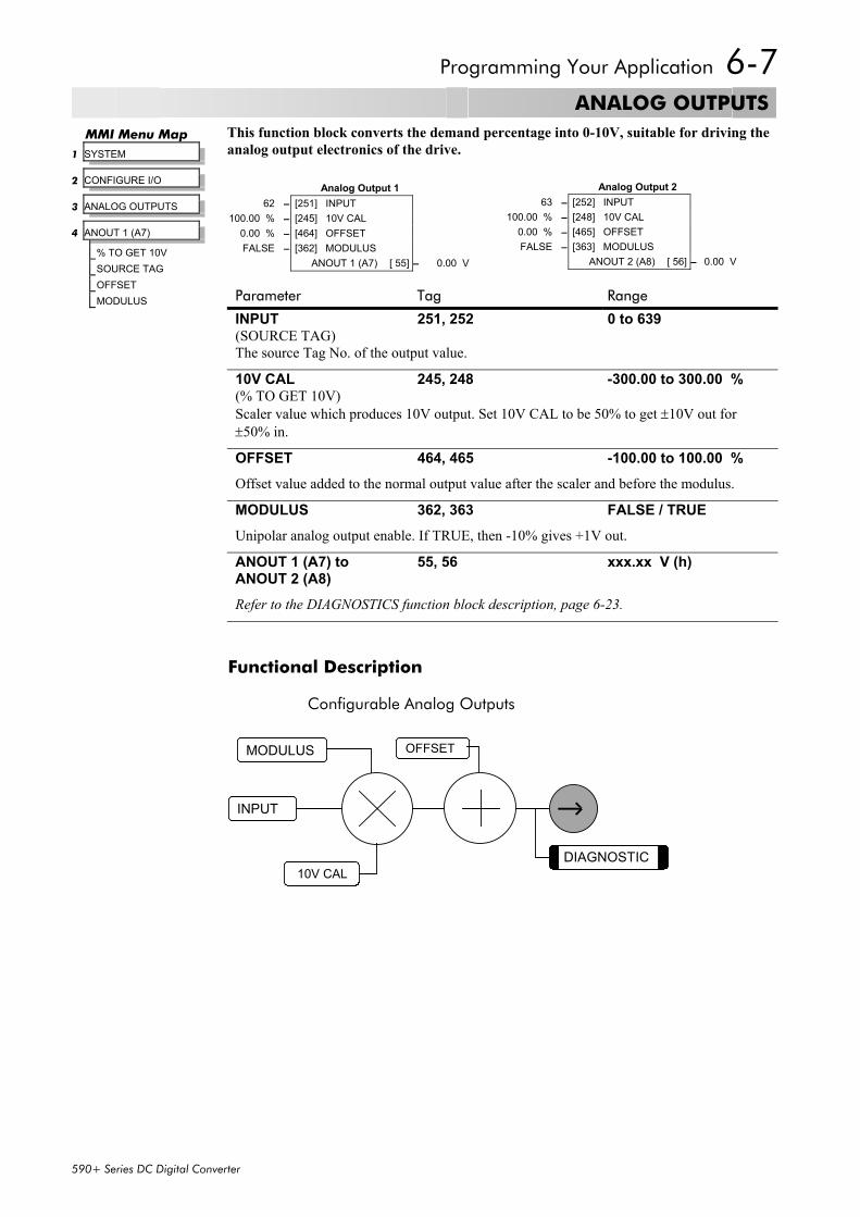
Function Block Descriptions..........................................................................6-4• ANALOG INPUTS .................................................................................6-5• ANALOG OUTPUTS..............................................................................6-7• AUX I/O...............................................................................................6-8
Contents
Contents Page
Cont.8
• BLOCK DIAGRAM (MMI only) ..............................................................6-13• CALIBRATION ....................................................................................6-14• CONFIGURE DRIVE ............................................................................6-17• CURRENT LOOP.................................................................................6-19• CURRENT PROFILE .............................................................................6-22• DIAGNOSTICS ...................................................................................6-23• DIAMETER CALC. ...............................................................................6-29• DIGITAL INPUTS .................................................................................6-31• DIGITAL OUTPUTS .............................................................................6-34• FIELD CONTROL ................................................................................6-36• INERTIA COMP...................................................................................6-40• INHIBIT ALARMS.................................................................................6-41• INTERNAL LINKS.................................................................................6-44• JOG/SLACK .......................................................................................6-48• MENUS ..............................................................................................6-50• miniLINK ............................................................................................6-51• OP STATION......................................................................................6-52• PASSWORD (MMI only) .......................................................................6-54• PID ....................................................................................................6-55• PRESET ...............................................................................................6-59• RAISE/LOWER.....................................................................................6-61• RAMPS ...............................................................................................6-63• SETPOINT SUM 1 ...............................................................................6-68• SETPOINT SUM 2 ...............................................................................6-70• SPEED LOOP......................................................................................6-72• SPEED LOOP (ADVANCED).................................................................6-76• SRAMP ...............................................................................................6-78• STANDSTILL .......................................................................................6-81• STOP RATES .......................................................................................6-83• SYSTEM PORT P3................................................................................6-86• 5703 SUPPORT ..................................................................................6-87• TAPER CALC.......................................................................................6-88• TEC OPTION......................................................................................6-90• TENS+COMP CALC. ..........................................................................6-91• TENS+COMP CALC. ..........................................................................6-93• TORQUE CALC. .................................................................................6-94• USER FILTER .......................................................................................6-95
Chapter 7 TRIPS AND FAULT FINDING
Trips ..............................................................................................................7-1What Happens when a Trip Occurs..........................................................................7-1
• Converter Indications ............................................................................7-1• Operator Station Indications..................................................................7-1
Resetting a Trip Condition........................................................................................7-1
• LAST ALARM.........................................................................................7-5• HEALTH WORD ....................................................................................7-5• HEALTH STORE ....................................................................................7-5
Hexadecimal Representation of Trips........................................................................7-6Power Board LED Trip Information (Frame 4, 5 & H) .................................................7-7Using the MMI to Manage Trips ...............................................................................7-8
Test Points ............................................................................................................7-12
Chapter 8 ROUTINE MAINTENANCE AND REPAIR
Maintenance .................................................................................................8-1• Service Procedures................................................................................8-1• Preventive Maintenance.........................................................................8-1
Repair ...........................................................................................................8-1Saving Your Application Data ..................................................................................8-1Returning the Unit to SSD Drives ..............................................................................8-2Disposal .................................................................................................................8-2Technical Support Checks........................................................................................8-3Fuse Replacement (Frame H) ...................................................................................8-4
• Set-up Notes.........................................................................................9-4• Current Control ....................................................................................9-5• Voltage Control ....................................................................................9-5• Field Weakening...................................................................................9-5• Standby Field........................................................................................9-5
Contents
Contents Page
Cont.10
Chapter 10 PARAMETER SPECIFICATION TABLE
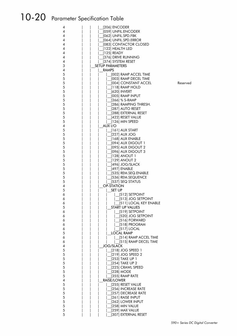
Specification Table: Tag Number Order.....................................................10-2Parameter Table: MMI Menu Order........................................................10-19
Chapter 11 TECHNICAL SPECIFICATIONS
Environmental Details............................................................................................11-1EMC Compliance..................................................................................................11-1Electrical Ratings - Power Circuit ............................................................................11-2Power Supply Details .............................................................................................11-3Auxiliary Power Supply Details................................................................................11-3AC Line Choke (Frames 1, 2, 3, 4 & 5) ..................................................................11-4AC Line Choke (Frame H)......................................................................................11-5External AC Supply (RFI) Filters...............................................................................11-5Power Semiconductor Protection Fuses (Frames 1, 2, 3, 4 & 5) ................................11-6Power Semiconductor Protection Fuses (Frame H) ...................................................11-6Power Supply Fuses ...............................................................................................11-7Field Fuses............................................................................................................11-7Earthing/Safety Details ..........................................................................................11-7Terminal Definitions (Digital/Analog Inputs & Outputs)............................................11-8Terminal Information - Power Board (Frames 1, 2, 3, 4 & 5) ...................................11-9Terminal Information – Control Board..................................................................11-12Terminal Information – Control Board..................................................................11-13Terminal Information – Control Board..................................................................11-14Terminal Information – Control Board..................................................................11-15Terminal Information (Frame H)...........................................................................11-16Terminal Information – Option Boards .................................................................11-17Wiring Requirements for EMC Compliance ...........................................................11-17Wire Sizes and Termination Tightening Torques (Frames 1, 2, 3, 4 & 5).................11-18Termination Tightening Torque (Frame H) ............................................................11-19Cooling Fans ......................................................................................................11-19Spares List ..........................................................................................................11-20
Chapter 12 CERTIFICATION FOR THE CONVERTER
Requirements for EMC Compliance ............................................................12-1Minimising Radiated Emissions ..............................................................................12-1Earthing Requirements...........................................................................................12-1
Cabling Requirements ...........................................................................................12-2• Planning Cable Runs...........................................................................12-2• Increasing Motor Cable Length............................................................12-2
EMC Installation Options .......................................................................................12-3• Screening & Earthing (cubicle mounted, Class A)..................................12-3• Star Point Earthing ..............................................................................12-4• Sensitive Equipment ............................................................................12-5
Contents
Contents Page
Cont.11
Requirements for UL Compliance ...............................................................12-6• Motor Overload Protection ..................................................................12-6• Branch Circuit/Short Circuit Protection Requirements ............................12-6• Short Circuit Ratings............................................................................12-6• Field Wiring Temperature Rating .........................................................12-7• Operating Ambient Temperature .........................................................12-7• Field Wiring Terminal Markings ...........................................................12-7• Power and Control Field Wiring Terminals ...........................................12-7• Field Grounding Terminals..................................................................12-7• Field Terminal Kits ..............................................................................12-7• Fuse Replacement Information.............................................................12-7
Recommended Wire Sizes (Frames 1, 2, 4 & 5) ......................................................12-8Recommended Wire Sizes (Frame H)......................................................................12-8European Directives and the CE Mark........................................................12-9CE Marking for Low Voltage Directive ....................................................................12-9CE Marking for EMC - Who is Responsible? ...........................................................12-9
• Legal Requirements for CE Marking...................................................12-10• Applying for CE Marking for EMC......................................................12-10
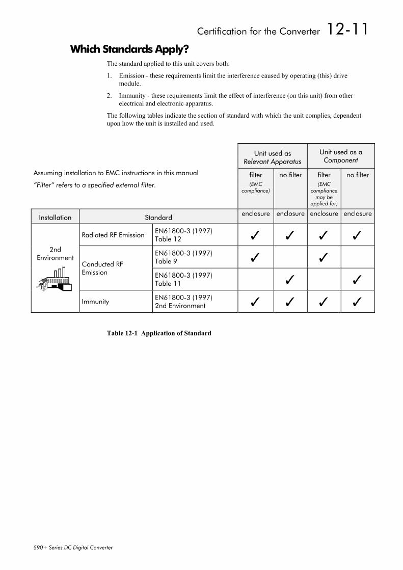
Which Standards Apply?......................................................................................12-11Certificates .........................................................................................................12-13
Chapter 13 STANDARD AND OPTIONAL EQUIPMENT
Standard Equipment...................................................................................13-1Power Board Circuit Descriptions ...........................................................................13-1
Communications Technology Option ..........................................................14-1Config Ed Lite .......................................................................................................14-1System Port (P3)..........................................................................................14-1UDP Support.........................................................................................................14-1
• UDP Menu Structure............................................................................14-2• UDP Transfer Procedure......................................................................14-2• MMI Dump.........................................................................................14-3
5703 Support .......................................................................................................14-4• Commissioning the 5703/1 ................................................................14-5
1 GETTING STARTEDSystem DesignThe 590+ Series Converter is designed for use in a suitable enclosure, with associated controlequipment. The unit accepts a variety of standard three-phase ac supply voltages dependingupon the model, and is suitable for the powering of DC shunt field and permanent magnetmotors, providing controlled dc output voltage and current for armature and field.
All units are designed for simple and economical panel mounting using keyhole slots. Plug-incontrol connectors simplify the fitting and removal of the unit to the panel.
Where possible, standard parts are used throughout the range thereby reducing the variety ofspare parts required to maintain a multi-drive system. For example, the same basic controlboards are used in all types of three-phase armature controller regardless of horsepower orbridge configuration.
The control circuit is totally isolated from the power circuit thus simplifying the interconnectionof controllers within a system and improving operator safety. The coding circuitry adjustsautomatically to accept supply frequencies between 45-65Hz and possesses high immunity tosupply-borne interference. The armature controllers are phase rotation insensitive.
Control and CommunicationsThe Converter is controlled by a 16 bit Microcontroller providing advanced features such as:
• Complex control algorithms which are not achievable by simple analog techniques.
• Software-configurable control circuitry built around standard software blocks.
• Serial link communications with other drives or a PC for advanced process systems.
The Operator Station gives access to parameters, diagnostic messages, trip settings and fullapplication programming.
Regenerative and Non-Regenerative ModelsThe motor armature controllers include both regenerative and non-regenerative models:
• Regenerative controllers consist of two fully-controlled thyristor bridges and a field bridgewith full transient and overload protection, together with sophisticated electronic control ofacceleration and deceleration, speed and torque in both directions of rotation.
• Non-regenerative controllers consist of one fully-controlled thyristor bridge and a fieldbridge with full transient and overload protection, together with its associated electroniccontrol circuitry, and provide accurate speed and/or torque control in one selected directionof rotation.
Field RegulatorA field regulator is fitted as standard. The regulator consists of a full-wave half controlled singlephase thyristor bridge with transient and overload protection. It provides either a fixed voltageor fixed current source, depending upon the selected mode of operation for constant torqueapplications. The field current mode of operation can be further enhanced to provide fieldweakening for drive control motors which require extended speed or constant horsepowercontrol.
1-2 Getting Started
590+ Series DC Digital Converter
Equipment Inspection and Storage• Check for signs of transit damage• Check the product code on the rating label conforms to your requirement.
If the unit is not being installed immediately, store the unit in a well-ventilated place away fromhigh temperatures, humidity, dust, or metal particles.
Refer to Chapter 2: “An Overview of the Converter” to check the rating label/product code.Refer to Chapter 8: “Routine Maintenance and Repair” for information on returning damagedgoods.Refer to Chapter 11: “Technical Specifications” - Environmental Details for the storagetemperature.
Packaging and Lifting Details
Caution The packaging is combustible and, if disposed of in this manner incorrectly, may lead to
the generation of lethal toxic fumes.
Save the packaging in case of return. Improper packaging can result in transit damage.
Use a safe and suitable lifting procedure when moving the drive. Never lift the drive by itsterminal connections.
Prepare a clear, flat surface to receive the drive before attempting to move it. Do not damageany terminal connections when putting the drive down.
Refer to Chapter 11: “Technical Specifications” - Mechanical Details for unit weights.
About this ManualThis manual is intended for use by the installer, user and programmer of the 590+ SeriesConverter. It assumes a reasonable level of understanding in these three disciplines.
Note: Please read all Safety Information before proceeding with the installation and operationof this unit.
Enter the “Model No” from the rating label into the table at the front of this manual. There isalso a column for you to record your application’s parameter settings in the table in Chapter 10.It is important that you pass this manual on to any new user of this unit.
This manual is for the following models from the 590+ Converter Series:
• Three phase, regenerative, four quadrant armature controllers:590+
• Three phase non-regenerative, two quadrant armature controllers:591+
• 590+ Door
Initial StepsUse the manual to help you plan the following:
• conformance with local installation requirements
• supply and cabling requirements
Getting Started 1-3
590+ Series DC Digital Converter
OperationKnow your operator:
• how is it to be operated, local and/or remote?
• what level of user is going to operate the unit?
• decide on the best menu level for the Operator Station (where supplied)
Programming (Operator Station or suitable PC programming tool only)Know your application:
• plan your “block diagram programming”
• enter a password to guard against illicit or accidental changes
• learn how to back-up your application data
• customise the Operator Station to the application
How the Manual is OrganisedThe manual is divided into chapters and paragraphs. Page numbering restarts with everychapter, i.e. 5-3 is Chapter 5, page 3.
Application Block DiagramYou will find this at the rear of the manual. The pages unfold to show a complete blockdiagram, this will become your programming tool as you become more familiar with thesoftware.
Quick-Start Guide
Chapters 3 and 4 install and runthe product
details the Operator Stationand menu system
Chapter 5
Chapter 11
technical detailsholds many of the
1-4 Getting Started
590+ Series DC Digital Converter
An Overview of the Converter 2-1
590+ Series DC Digital Converter
2 AN OVERVIEW OF THE CONVERTER
How it WorksNote: Refer to Chapter 9: “Control Loops” for a more detailed explanation.
In very simple terms, the Converter controls the dc motor with the use of Control Loops - aninner Current Loop and an outer Speed Loop. These control loops can be seen in theApplication Block Diagram. The block diagram shows all the Converter’s software connections.
Using the Operator Station, you can select the control loops to be used by the Converter toprovide either:
• Current Control
• Speed Control (default)
It is usual to supply a Current or Speed Feedback signal to the appropriate loop for moreeffective control of the Converter. Current Feedback sensors are built-in, whereas SpeedFeedback is provided directly from the armature sensing circuit (default), or by tachogenerator,encoder or Microtach connection to the relevant option board.
When in Speed Control,you can modify theperformance of theConverter further bycontrolling the motorfield, i.e. Field Control.By weakening the fieldcurrent, you can obtainan increase in motorspeed beyond thatnormally achievable forthe rated ArmatureVoltage of the dc motor.
The Converter is controlled remotely using digital/analog inputs and outputs, or locally usingthe Operator Station.
By plugging in a COMMS Option Technology Box, the Converter can be linked into a networkand controlled by a PLC/SCADA or other intelligent device.
Field Current 5.7A
Voltage 200V
Speed
speed increasedue to fieldweakening
armature voltageremains constant
field currentreduced
basespeed
Armature
REMOTE START/STOP
REMOTE
LOCAL START/STOP
LOCALSPEED CONTROL SPEED CONTROL
DEFAULT
SPEED SETPOINTSPEED SETPOINT
LOCAL CONTROLREMOTE CONTROL
2-2 An Overview of the Converter
590+ Series DC Digital Converter
Control Features
Control Control Circuits Fully isolated from power circuit (SELV)
Output Control • Fully controlled 3-phase thyristor bridge• Microprocessor implemented phase control extended
firing range• For use on 50 or 60Hz supplies with a frequency
compliance range of 45 to 65Hz• Phase control circuits are phase rotation insensitive
Control Action • Fully digital• Advanced PI with fully adaptive current loops for
optimum dynamic performance• Self Tuning Current Loop utilising "Autotune"
algorithm• Adjustable speed PI with integral defeat
Speed Control • By Armature Voltage feedback with IRcompensation
• By Encoder feedback or analog tachogeneratorSpeed Range 100 to 1 typical with tachogenerator feedbackSteady StateAccuracy
• 0.01 % Encoder Feedback with Digital setpoint(serial link or P3)
• 0.1 % Analog Tach Feedback• 2 % Voltage Feedback• Absolute (0.0% error) using QUADRALOC Mk II
5720 Digital ControllerNote: Long term analog accuracy is subject to
tachogenerator temperature stability.
Adjustments All adjustments in software can be altered bythe Operator Station or via serial communications. TheOperator Station provides monitoring and adjustment ofparameters and levels, in addition to diagnostic facilities.
Protection • High energy MOVs• Overcurrent (instantaneous)• Overcurrent (inverse time)• Field failure• Speed feedback failure• Motor overtemperature• Thyristor Stack overtemperature• Thyristor "Trigger" failure• Thyristor Snubber Network• Zero-speed detection• Standstill logic• Stall protection
Diagnostics • Fully computerised with first fault latch andautomatic display
• Digital LCD monitoring• Full diagnostic information available on
RS422/RS485• LED circuit state indication
Table 2-1 Control Features
An Overview of the Converter 2-3
590+ Series DC Digital Converter
Understanding the Product Code
Model Number (Europe)The unit is fully identified using an alphanumeric code which records how the Converter wascalibrated, its various settings when despatched from the factory, and the country of origin.
The Product Code appears as the “Model No”. Each block of the Product Code is identified asbelow:
Model Number (Europe)
BlockNo.
Variable Description
1 XXXX Generic product
590P : 590+ 4Q DC Drive591P : 590+ 2Q DC Drive
2 XXXX Four digits identifying the maximum dc output current rating that may becalibrated for each size of product:
3 XXX 3 digits identifying the nominal 3 phase ac power, supply voltage:
220 110 to 220V (±10%) 50/60Hz500 220 to 500V (±10%) 50/60Hz600 500 to 600V (±10%) 50/60Hz (Frame 4 & 5 only)690 500 to 690V (±10%) 50/60Hz (Frame H only)
4 XXXX 4 digits describing the mechanical package including livery and mechanicalpackage style:
First two digits (on the left) Livery00 Standard SSD Livery05 Distributor Livery01-04 and 06-99 Defined customer liveries TBA
Third digit Mechanical Package Style1 Standard (IP20), protected panel mounting4 Panel Mounting IP20 plus Roof Vent Kit
(Frame 4 only)
Fourth digit Operator Station0 No operator station1 Built-in 6901 operator station
5 XX Two characters specifying the user interface language:
UK = EnglishFR = FrenchGR = German (refer to Customer Services)SP = Spanish (refer to Customer Services)IT = Italian (refer to Customer Services)
2-4 An Overview of the Converter
590+ Series DC Digital Converter
Model Number (Europe)
BlockNo.
Variable Description
6 XXX Up to three characters specifying the feedback option (one must be fitted):
ARM = Armature VoltageAN = Analog TachoENW = Encoder (wire-ended)ENP = Encoder (plastic fibre-optic)ENG = Encoder (glass fibre-optic)
7 XXXXX Up to five characters specifying the protocol for the 6055 communicationsTech Box option:
0 = No Comms option fittedEI00 = RS485 (EI BINARY, EI ACSII or MODBUS RTU)PROF = PROFIBUS DPLINK = LINKDNET = DEVICENETCAN = CANOPENMBP = MODBUS+ENET = ETHERNETCNET = CONTROLNET
8 XXX Up to three characters specifying the auxiliary mains power supply:
0 = Universal auxiliary supply 115 to 230V (±10%) 50/60Hz(only available on drives below 165A and above 1200A inclusive)
115 = 110V to 120V (±10%) 50/60Hz230 = 220V to 240V (±10%) 50/60Hz
9 XXX Up to three characters specifying engineering special options:
000 = No special option
Catalog Number (North America)The unit is fully identified using an alphanumeric code which records how the Converter wascalibrated and its various settings when despatched from the factory.
The Product Code appears as the “Cat No”. Each block of the Product Code is identified asbelow:
Catalog Number (North America)
BlockNo.
Variable Description
1 XXXX Generic product
590+ : 590+ 4Q DC Drive591+ : 590+ 2Q DC Drive
XXXX Four further digits identifying the maximum dc output current rating thatmay be calibrated for each size of product:
1 Main door assembly 7 Speed feedback technology card (optional)2 Terminal cover 8 Control terminals3 Terminal cover retaining screw 9 Operator station port4 Blank cover 10 RS232 programming port (P3)5 6901 operator station (optional)6 COMMS technology box (optional)
2-8 An Overview of the Converter
590+ Series DC Digital Converter
590+ Controller (Frame 3)
L1
4
L2 L3
1
2
7 63
A-
A+
5
270A unit illustrated
DoorAssembly
Product Code 590PXD/....
1 Main converter assembly 5 Busbars - main power output2 Door assembly 6 IP20 Top Cover3 Field wiring terminals 7 IP20 Fan Housing (where fitted)4 Busbars - main power input
An Overview of the Converter 2-9
590+ Series DC Digital Converter
590+ Controller (Frames 4 & 5)
AssemblyDoor
1
2
L1 L2 L3
A+ A-
6
4
5
3
field & auxiliaryconnectionsvia grommet
Product Code 590PD/....
8
97
L1 L2 L3
A- A-
When Frame 5, both terminals are for A+ connections
10
Frame 4 Frame 5
1 Main converter assembly 6 Auxiliary supply, contactor and motor thermistor terminals2 Standard door assembly 7 Frame 4 External vent (where fitted)3 Motor field terminals 8 Contactor Control Select4 Busbars - main power input 9 Frame 5 External vent (where fitted)5 Busbars - main power output 10 Terminal Cover (Frame 5)
On the Frame 5,both the Master andSlave drives must beindividually earthed
2-10 An Overview of the Converter
590+ Series DC Digital Converter
590+ Product (Frame H)
LNNMC
AuxiliaryPower
Contactor
FL1FL2F+
F-
MVA+
MVA-
Armature terminals arefitted to right hand sideof the drive but canbe moved to the lefthand side if necessary
L1 L2 L3
Mains Supply Terminals
A-
A+
PowerControlTerminals
supply and and outputterminals plusexternal armaturevoltage sense
Keyhole Mounting Slots(8 off for 4Q Regenerative)
Earth/PE(On the Backof the Converter)
EUROTHERMDRIVES
590+SERIES
Removable Lifting Brackets(4 off)
(6 off for 2Q Non-Regenerative)
Main
Coil
Motor fieldDoor
AssemblyProduct Code
590PXD/....
Installing the Converter 3-1
590+ Series DC Digital Converter
3 INSTALLING THE CONVERTERIMPORTANT: Read Chapter 12: “Certification for the Converter” before installing this unit.
Refer to “Installation Drawings”, page 3-29 for further information.
Mechanical Installation
Unpacking the Converter
Caution The packaging is combustible and this action may produce lethal toxic fumes.
Save the packaging in case of return. Improper packaging can result in transit damage.
Frame H PackagingLarge converters (Frame H) are supplied in special packaging with removable sides. Remove allfixings from the drive, see Figure 3-1.
Lifting the ConverterUse a safe and suitable lifting procedure when moving the drive. Never lift the drive by itsterminal connections.
Prepare a clear, flat surface to receive the drive before attempting to move it. Do not damageany terminal connections when putting the drive down.
Frame 4 & 5 converters have lifting eyes and a shipping plate fitted to the base to enable thedrive to be set-on-end by a forklift. Remove the shipping plate before wiring the powerterminals.
Frame H converters require the following:
• The drive is supplied with a lifting bracket fitted to each corner for hoisting. Remove thebrackets when the drive is in its final position, however, the fixings MUST be re-fitted.Refer to Chapter 11: “Technical Specifications” - Fixing Types and Torques.
• A shipping plate is fitted to the base to enable the drive to be set-on-end by a forklift.Remove the plate before wiring the power terminals.
3-2 Installing the Converter
590+ Series DC Digital Converter
Product Dimensions
40A - 165A
D
BE1
A
CE2
15A - 35A
D
BE1
A
CE2
Frame 1 Frame 2180A - 270A
A
C
D
BE1
Frame 3
Current Rating (A) Weight in Kg (lbs) Overall Dimensions Fixing Centres
1200 - 2700 See below * 850 (33.5) 1406 (55.3) 417 (16.4) 810 (31.9) 78 (3.1) 4 x 400 (15.7)
1200 - 2700 See below * 850 (33.5) 956 (37.6) 417 (16.4) 810 (31.9) 78 (3.1) 3 x 400 (15.7)
*590+ drive weighs 270Kg (595.4 lbs) without packaging and fan assembly 591+ drive weighs 160kg (352.8 lbs) without packaging and fan assembly
Fan weighs 18.5Kg (40.8 lbs)Dimensions are in millimetres (inches)
Refer to the Installation Drawings
Installing the Converter 3-3
590+ Series DC Digital Converter
Mounting the ConverterNote: General installation details are given below for mounting the Converter, however, if you
are installing the unit with an EMC filter refer to “External AC Supply EMC FilterInstallation”, page 3-27.
Mount the unit vertically on a solid, flat, vertical surface. It is mounted using bolts or screwsinto four fixing points (keyhole slots). The design allows the use of 100mm grid fixing.
It must be mounted inside a suitable cubicle. To comply with the European safety standardsVDE 0160 (1994)/EN50178 (1998), the cubicle must require a tool for opening.
Note: Holes for the mounting bolts or screws must be placed accurately.
Cover any units all ready mounted to the panel to protect them from stray metal filings whiledrilling mounting holes.
General Mounting HintsInsert the mounting studs from the rear of the panel. Attach lock washers and nuts part way onto the lower mounting studs; these will help to keep the drive in place when mounting.
Caution Use proper lifting techniques when lifting and moving.
Lift the drive and engage the bottom slots safely on to the studs between the panel and lockwashers/nuts you have just fitted. Engage the top slots with the remaining mounting studs andfinger tighten the drive to the panel with lock washers and nuts. Finally, use the socket wrenchto tighten all nuts securely.
Check the drive and its housing for packing material, mounting debris, or any other material thatcould damage and/or restrict the operation of the equipment.
Recommended Tools
Socket wrench With a 6 Inch extension
Deep sockets M10, M13, M17, 7/16”, 1/2”
Screwdrivers Phillips No.2, flat blade - 0.5 x 3.0mm, 0.8 x 4.0mm
Wire cutters Small
Ventilation and Cooling RequirementsRefer to Chapter 11: “Technical Specifications” - Cooling.
The Converter gives off heat in normal operation and must therefore be mounted to allow thefree flow of air through the air entries and exits. Maintain the minimum air clearances given onthe drawings to ensure that heat generated by other adjacent equipment is not transmitted to theConverter. Be aware that other equipment may have its own clearance requirements. Whenmounting two or more 590+’s together, these clearances are cumulative.
Ensure that the mounting surface is normally cool.
Installing the Fan (Frame H)Refer to Chapter 11: “Technical Specifications” - Cooling for fan ratings
The fan unit supplied should be installed on the cubicle, with or without ducting (refer to theInstallation Drawing). The drive is force-cooled using the fan units supplied with the drive. As ageneral rule allow at least 150mm (6 inches) of clear space above and below the drive for freeair flow. We suggest the cubicle has an air inlet at the base of the cubicle equivalent to 4ft²,variable depending upon the filter type used, to allow the maximum throughput of air.
The fan assembly provided is permanently wired as shown below.
3-4 Installing the Converter
590+ Series DC Digital Converter
Figure 3-2 Frame H Fan Wiring Diagram
Installing the External Vent Kit (Frames 4 & 5)SSD Part Numbers: Frame 4 : LA466717U001
Frame 5 : LA466717U002Refer also to Figure 3-18 page 3-34 and Figure 3-20 page 3-36.
Upper Housing
Foam gasket stretchesover duct prior to attaching upper housing
Duct slides down betweenclip and mounting panelwithin the sides of thedrive housing
Fit duct clipunder fastenersat top of drivetight againstmounting panel
Figure 3-3 Frames 4 & 5 External Vent Kit
115V ac1234
PE/GRD
L
N
115V ac + 10%50/60Hz
230V ac1234
PE/GRD
L
N
230V ac + 10%50/60Hz
LNLN
LNLN
4.5A
2.25A
Caution
PE/GRDFN4
FN3FN2
FN1
Installing the Converter 3-5
590+ Series DC Digital Converter
AC Line ChokeWe recommend that you always use the specified ac line choke with the Converterto provide a known supply impedance for effective operation of the thyristor transientsuppression circuits. At least 1% line impedance should be provided in the supply side of theconverter.
Refer to Chapter 11: “Technical Specifications” - AC Line Choke for selection details.
FilteringNote: Refer to Chapter 12: "Certification for the Drive" - European Directives and the CE Mark.
For compliance in Europe with EN61800-3 Table 11:
• The CE marking of drives whose armature current >100A is applicable withoutfiltering.
• The CE marking of drives whose armature current <100A is only applicable withfiltering. The drive requires one of the following:
1. The specified filter given in Chapter 11(also refer to External AC Supply EMC Filter Installation, page 3-27)
2. Compliant filtering offered by the System
3. Capacitors fitted between phase and earth (see Figure 3-4)
StartContactor
ACLine
Choke Drive
C4
C1, C2 & C3
Suitable BranchProtection Fuse
orCircuit Breaker
PE
(must befitted)
Capacitor Reference Number Capacitor Value/Type
C1, C2, C3 3.0µF 400V, EMI suppressor type Class X1
C4 1.0µF 400V, EMI suppressor type Class X1
Figure 3-4 AC Line Choke and Capacitors fitted toFrame 1 (15A & 35A) & Frame 2 (40A & 70A) Drives
3-6 Installing the Converter
590+ Series DC Digital Converter
Frame H Additional InformationRemoving the Cover (Frame H)The cover is manufactured from sheet metal and weighs:-
To remove the cover use a flat headed screwdriver toundo the two screws at the base of the cover.
Now lift the cover base outwards and upwards, once thecover has been raised two centimetres it can now beremoved.
To replace the cover follow the procedure in reverse,engaging the locating studs at the top, moving into finallocation and tightening fixing screws.
Changing DC Output Terminals (Frame H)• Remove the left-hand cover plate(s) and retain the cover and screws.• Remove and retain the 12 M6 nuts clamping the outgoing terminals to the cross plates.• Remove the 12 M6 bolts securing the outgoing busbar assembly (assemblies). Remove the
assembly (assemblies).• Carefully remove the gasket(s) for use on the left-hand side.• Refit the cover to the right-hand side of the drive.• Refit the gasket to the left-hand side of the drive.• Refit the terminal assemblies.
Note: The 2Q terminal assembly is not polarised and may be fitted in any orientation. The 4Qterminal assemblies are handed and must be reversed to fit on the left-hand side.
• Move the terminal markers as appropriate, the A+ terminal will still be at the bottom or ACinput at the end of the product.
Tighten terminal assembly bolts to the torque given in Chapter 11.
SideView
2cmRemove2 screws
Installing the Converter 3-7
590+ Series DC Digital Converter
Electrical InstallationIMPORTANT: Please read the Safety Information on page Cont. 3 & 4 before proceeding.
WARNING! Ensure that all wiring is electrically isolated and cannot be made “live”
unintentionally by other personnel.
Note: Refer to Chapter 11: “Technical Specifications” for additional Cabling Requirements andTerminal Block Wire Sizes.
Cables are considered to be electrically sensitive, clean or noisy. You should already haveplanned your cable routes with respect to segregating these cables for EMC compliance.If not, refer to Chapter 12: “Certification for the Converter”.
If the controller is to be operating in a regenerating mode for extended periods acting as a loadgenerator for another machine, it is advisable to fit additional protection in the armature circuit.A dc fuse or high speed circuit breaker will provide this protection. If in doubt, contact SSDDrives.
Cable Gland RequirementsUse a metal gland toconnect to the cubiclebackplate, near theVSD (variable speeddrive). It must becapable of securing a360 degree screenedconnection to giveEMC compliance. A360 degree screenedconnection can beachieved as shown.
We suggest a rubbergrommet should befitted on holes where acable gland is not used.
Figure 3-7 360 Degree Screened Connection
590+converter
external
filtermotor
powersupply
(clean)
(noisy)
(noisy)
signal/control cable(sensitive)
motor cable
fuse or suitablecable accircuit breaker
(RCD notrecommended)
chokecontactor
field cable
Not fitted toFrame H units
(optional)
Figure 3-5 Cabling Requirements
PE power wiringto motor
rubbergrommet
metal gland musthave 360 degreescreened connectionfor EMC compliance
MPE Protective Earth
Internationalgrounding symbol
1 rubber grommet 2 metal cable gland
for example
Figure 3-6 Cable and Screen Fixings
If fitted, the AC filterMUST be placedbetween the supplyand the choke.
Failure to do so willresult in unreliableoperation of the driveand reduced lifetimeof the filter.
3-8 Installing the Converter
590+ Series DC Digital Converter
Minimum Connection RequirementsIMPORTANT: If in doubt about the connection of the DC motor to the drive, contact SSD Drives.
Note: Because of the complexity of showing all possible configurations, this Chapter deals onlywith a `general purpose’ operation as a basic speed controller. Special wiring optionsusually form part of a customer-specific system and connection details will be providedseparately.
Minimum connections to operate the drive safely are shown using bold lines in thefollowing circuit diagrams. These connections are highlighted in text with thesymbol opposite. The remaining connections are not necessary for a “quick start-up”.
The Converter is using the default Armature Voltage feedback when following the`minimum connection’ instructions.
WARNING! Power terminals carry electrical voltage which can be lethal. Never work on any
control equipment or motors without first removing all power supplies from theequipment.
Caution Make sure all wiring connections meet or exceed applicable local and National Electrical
Codes. Be sure to fit branch circuit and motor overload protection.
IMPORTANT: If fitting your own "Power On" indicator lamp, annunciator, etc., this should be switchedby an auxiliary contactor of the main contactor, not by the controller auxiliary relay.
To avoid damaging the drive NEVER carry out high voltage resistance or dielectricstrength tests without first completely disconnecting the drive from the circuit being tested.
Power CablesNote: Refer to Chapter 11: “Technical Specifications” - Wire Sizes and Termination Tightening
Torques.
• minimum rating of 1.1 x full load current (Europe)
• minimum rating of 1.25 x full load current (UL)
Control WiringNote: Refer to Chapter 11: “Technical Specifications” for Control Terminal information.
• Control wiring must have a minimum cross-section area of 0.75mm2 (18AWG).
• Use screened control cables to comply with EMC requirements.
• Feed the control cables into the drive and connect to the control terminals. Refer to theconnection label on the inside of the terminal cover. Close the terminal cover.
IMPORTANT: All connections made to terminal blocks A, B and C must be isolated signal voltages.
Important ConnectionsThe following connections must be made for the drive to run:
• Terminals TH1 and TH2 must be linked if a thermostat is not fitted.
• Terminals C1 and C2 must be linked if an External Trip interlock is not required.
Main AC PowerThere is no specific phase connection to terminals L1, L2 and L3 as the controller isphase rotation independent.
Branch ProtectionAC current = 0.83 x DC Armature Current
You must provide branch circuit protection using a suitable fuse or Type 2 circuitbreaker (RCD, ELCB, GFCI circuit breakers are not recommended, refer to “Earth FaultMonitoring Systems”, page 3-28).
Also refer to Chapter 12: “Certification for the Converter” - Requirements for ULCompliance.
Semi-Conductor ProtectionFrame H drives contain high speed semi-conductor fuses. For all other frame sizes,always provide high-speed thyristor fusing to protect the thyristor stack in the case ofdirect output short circuits. Semiconductor fuses may be used as Branch Protection onsingle-drive systems.
IMPORTANT: If a motor becomes completely short-circuited, the current trip(OVER I TRIP) will not protect the Converter.
Refer to Chapter 11: “Technical Specifications” - Power Semiconductor ProtectionFuses.
3-Phase External ContactorThe contactor does not switch current and is primarily for disconnection and sequencingof the power bridge. It must be energised directly from the controller by a coil with arating suitable (AC1) for the controller concerned. No additional series contacts orswitches are permitted since they will interfere with the sequencing of the controller andcause unreliability and possible failure. Connect to main contactor terminals Con Land Con N only as described in Chapter 11, otherwise unreliable or dangerousoperation may occur - do not connect to a PLC input or sensitive relay.Slave Relay : If the 3-phase contactor has a coil with an inrush greater than 3A, a slaverelay MUST be used to drive the contactor coil. The contactor and slave relay (ifrequired) MUST have coil voltages compatible with the controller auxiliary supplyvoltage.
DO NOT use a slave relay with a coil current less than 25mA as it may beenergised by the contact suppression network.
Frames 4 & 5 : A relay jumper (CONN1) is provided on the power board enablingterminals 3 & 4 to be powered (auxiliary supply - default position), or to be volt-free (forcustomers own contactor supply). Refer to Chapter 13: “AH466701U001, U002, U003(Frames 4 & 5)”.DC Contactor : A DC contactor can be used but the sequencing must be adjusted toaccomodate its use: an auxilliary normally open volt-free contact of the contactor mustbe connected in series with the "ENABLE" input (C5) to disable the drive until after thecontactor is closed.
AC Line ChokeIMPORTANT: Always fit the recommended choke. Refer to Chapter 11:
“Technical Specifications” - AC Line Choke.
We can provide suitable chokes, designed to connect directly to the drive terminals.Refer to Chapter 11: "Technical Specifications" - AC Line Choke.
DRIVE
CHOKE
CON
FILTER(optional)
Diagram
correct
of unitsplacement
shows
Installing the Converter 3-13
590+ Series DC Digital Converter
Power Connections cont.
Protective Earth ConnectionsPEConnect thedrive's PEterminal to anindependentearth/groundstar point.
Connect thisearth/groundstar point toProtectiveEarth.
IMPORTANT: The drive and filter (if fitted) must be permanently earthed. Eachconductor used for permanent earthing must individually meet therequirements for a protective earth conductor.
For installations to EN 60204 in Europe:• For permanent earthing, the converter requires either two individual incoming
protective earth conductors (<10mm² cross-section), or one conductor (≥10mm²cross-section) connected to an independent protective earth/ground point near thedrive.
• Run the motor protective earth/ground connection in parallel with the motor supplyconductors, ideally in the same conduit/screen/armour, and connect to anindependent protective earth/ground point near the drive.
Refer to Chapter 12: “Certification for the Converter” -Screening & Earthing (cubicle mounted, Class B).
Caution On the Frame 5, both the Master and Slave drives must be individually earthed.
Motor ArmatureA+A-
Connect themotorarmature toterminals A+and A-.
Connect the cable screen to the motor's PE terminal and the earth/ground star point.Connect the motor's PE terminal to the earth/ground star point.
For EMC compliant recommended cable lengths refer to Chapter 12: "Certification forthe Converter" - Cabling Requirements.
Note: If the drive is to operate in regenerating mode for long periods, it isadvisable to fit a dc fuse or high speed circuit breaker in the armaturecircuit. If in doubt consult SSD Drives.
Motor FieldF-F+
Connect themotor field (-)to terminal F-,and connectfield (+) toterminal F+.
Frame 3: Terminals F- & F+ = D3 & D4
Connect the cable screen to the independent earth/ground point.
If the motor has no field connections, is a permanent magnet motor, or if the field isderived externally, you must inhibit the FIELD ENABLE parameter (Tag No. 170) laterduring Set-up.
Terminals Th1 and Th2 must be linked if sensors are not fitted.
(Thermistor terminals for Frames 3 & H are on the Control Door Board).
We recommend that you protect the dc motor against overtemperature by the use oftemperature sensitive resistors or switches in the field and interpole windings of themachine. When the motor is fitted with over-temperature sensing devices, such asthermostats or PTC thermistors, these should be connected (in series) between terminalsTH1 and TH2.• Thermistors must have a combined working resistance of 750Ω or less, rising to
4kΩ at over-temperature. These thermistors are classified by IEC34-II as Mark A.• Temperature switches must be normally closed, and open at rated temperature.
The over temperature alarm will activate at 3kΩ. It is latched in software and must bereset by re-starting the Converter.
Note: The motor temperature alarm (THERMOSTAT) cannot be inhibited insoftware.
Frame 3: Terminals FL1 & FL2 = D1 & D2(Not available on Frame 1 units)Used if an external field supply is required to the controller for application reasons. Themagnitude of this voltage is determined by the desired field voltage. The supply must beprotected externally with suitable fuses.
IMPORTANT: The connection of the controller and the external field supplymust be consistent when using an externally supplied fieldregulator. Always derive the 1phase, 50/60Hz supply from theL1 (Red) and L2 (Yellow) phases of the main power supply,directly or indirectly through a single-phase transformer, with theRed phase connected to terminal FL1 and the Yellow phase toterminal FL2.
Note: You must provide branch circuit and overload protection.
To change the controller from an internal to an external field type refer to "MotorField Options", page 3-20.
Auxiliary SupplyL
NConnect thecontrol supplyto terminals L(Live) and N(Neutral).
Frame 3: Terminals L & N = D8 & D7
Single phase, 110/240V ac, 50/60Hz.
Note: The auxiliary supply chosen must equate to the contactor coil voltageused.
IMPORTANT: The auxiliary supply terminals must be connected directly to theincoming supply. No series sequencing switches or contacts arepermitted without consultation from SSD Drives.
Use suitable external fuse protection: the steady state current absorbed by the controlleris nominal, the external fuse is determined chiefly by considering the contactor holdingVA and the controller cooling fans. (Frame H fans are powered separately).
Refer to Chapter 11: “Technical Specifications” - Power Supply Fuses.
Frame H only
Installing the Converter 3-15
590+ Series DC Digital Converter
Control Connections
Speed DemandA1A4B3B4
Connect a 10kpotentiometerbetweenterminals A1and B3.Connect thewiper to A4.
Uni-directional Speed DemandThis connection provides a Uni-Directional Speed Demand for non-reversingapplications and the 2 Quadrant controller (591+):
Thus, zero speed demand is at the centre position on the potentiometer.
A4 RAMP INPUT SPEED LOOP
I LIMIT
I LOOP
A6
simplified view
In both cases, the Current Limit is controlled via terminal A6 (ANIN5).
Note: Terminals A1, B1 and C1 (Signal 0V) are the common reference points forall analog signals used in the drive.
Current LimitA6B3
Connectterminal A6 toB3.
This connection provides control of the Main Current Limit via terminal A6 (ANIN5).The "ANIN 5 (A6)" function block contains parameters to set up maximum/minimumvalues for the analog input, and a scaling ratio.
Adjust the main current limit using the MAIN CURR. LIMIT parameter [Tag No. 15]Refer to Chapter 6: "Programming Your Application" - CURRENT LOOP.
Fixed Current LimitFor normal operation of the main current limit, connect Terminal A6 (ANIN5)to Terminal B3 (+10V reference) and set the CURR.LIMIT/SCALER parameterto 200%. This allows the MAIN CURR.LIMIT parameter to adjust the currentlimit between 0 and 200% full load current.
Variable Current LimitIf external control of the main current limit is required, an additional10K potentiometer connected between Terminal B3 (+10V Ref) andTerminal B1(0V), with the wiper connected to Terminal A6(Analog I/P5) gives 0 to 200% of full load current provided that theMAIN CURR. LIMIT and CUR. LIMIT/SCALER parameters are setto 200%.
B3
B4
A4
+10V
-10V
RampInput
B3
A1
A4
+10V
0V
RampInput
SpeedDemand
Controls thespeed of the
motor
CurrentLimit
Controls theavailable
motortorque B3
B1
A6
+10V
0V
Current Limit
B3
A6
+10V
CurrentLimit
A4 B3
10Kpotentiometer
A6B4
3-16 Installing the Converter
590+ Series DC Digital Converter
Control Connections cont.
Program Stop/Coast StopB8B9C9
Connectterminals B8and B9 to C9via anEmergencyStop relay.
These connections provide a Program Stop (B8), and a Coast Stop (B9).Refer to Chapter 4: "Starting and Stopping Methods".
The "Emergency Stop" relay (normally-open, delay on de-energisation) should not bepart of the normal sequencing system which is implemented via the Start contacts, but isa relay which can be operated in exceptional circumstances where human safety is ofparamount importance.
• Removing 24V from B9 opens the main contactor via the relay• Removing 24V from B8 provides regenerative braking for 4 Quadrant 590+ drivesA regenerative drive can be stopped using a Normal Stop, a Program Stop, or anEmergency Stop. However, a non-regenerative drive can only be made to stop fasterthan friction and loading will allow by Dynamic Braking.
EnableC5C9 Connect
terminal C5 toC9.
Terminal C5 (Enable) must be connected to C9 (+24V) to allow the drive to run.
IMPORTANT: Connection via a switch is useful to inhibit the drive withoutopening the main contactor, however, it is not a safe mode ofoperation as the drive dc output is only reduced to zero. If theequipment controlled by the drive is to be serviced, then thismethod should be avoided and the drive disabled and isolated.
Start/RunC3C9 Connect
terminal C3 toC9 via aswitch.
When the single contact between C3 and C9 is closed the drive will run provided that:
• B8 & B9 are TRUE (+24V) - see "Emergency Stop" above
• C5 is TRUE (+24V) - see "Enable" above
When the single contact between C3 and C9 is opened the drive will decelerate themotor to zero speed at a rate determined by the STOP TIME parameter’s value and theMAIN CURR. LIMIT value. Refer to Chapter 6: “Application Programming” - STOPRATES for further details.
Jog/SlackC4C9 Connect
terminal C4 toC9 via aswitch orpushbutton.
• If the drive is stationary this switch provides a Jog facility.
• If the drive is running, this switch provides a Take-Up Slack facility.
For other user-definable operating modes, refer to Chapter 6: "Programming YourApplication" - JOG/SLACK for further details.
External TripC1C2 Connect
terminal C1 toC2
or
link terminalsif not required
Terminals C1 and C2 must be linked if an External Trip interlock is not required.This input terminal provides an external trip facility to any normally-closed trip switch ,e.g. for vent fan overload protection.
E'Stop
PROGSTOP
COASTSTOP
B8 B9 C9
Relay
Installing the Converter 3-17
590+ Series DC Digital Converter
Control Connections cont.
Drive HealthyC1B6 Connect
terminal C1 toB6 via a lamp(for example).
This is one of three digital output terminals that provide a +24V dc output signal undercertain conditions. They allow for the connection of relays which, in conjunction withthe Enable, Start/Run and Emergency Stop relay, can be used to enhance the safestarting and stopping of the controller.
The drive is "healthy" (TRUE) if there is no Start command.
These are configurable outputs and can be used as required in the control system design,i.e. cubicle door lamps, connection to a suitable PLC.
Digital OutputsB5B6B7
Userconnection toexternalequipment.
There are three digital output terminals that provide a +24V dc output signal undercertain conditions. They allow for the connection of relays which, in conjunction withthe Enable, Start/Run and Emergency Stop relay, can be used to enhance the safestarting and stopping of the controller.
These are configurable outputs and can be used as required in the control system design,i.e. cubicle door lamps, connection to a suitable PLC.
Speed Setpoint No. 1 (A2)Terminal A2 (Analog Input 1) is a direct speed demand by-passing the "Setpoint RampGenerator", and should be used if direct control is required.
Speed Setpoint No. 2 / Current Demand (A3)Terminal A3 (Analog Input 2) is a dual function terminal (either "Speed Setpoint No. 2"or "Current Demand") as selected by mode switch control "Current Demand Isolate",Terminal C8. As a speed setpoint, it can be used in the same way as Terminal A2.
If more than one speed setpoint is used, they are additive.
Auxiliary Current Clamp (-ve)A5B4C6C9
Connectterminal A5 toB4 to provide-10V, orsupplyexternally.
Connectterminal C6 toC9 to enablebipolarcurrentclamps.
Used to allow separate control of positive and negative Main Current Limits, forexample, in Winder applications.
Enable bipolar current clamps by providing 24V at terminal C6. Terminal A5 (ANIN4)is an Auxiliary Current Clamp (-ve), 0 to -10V. If driven positive, it will form a currentdemand.
The "ANIN 4 (A5)" function block contains parameters to set up maximum/minimumvalues for the analog input, and a scaling ratio.
With 24V at terminal C6, Terminal A6 (ANIN 5) acts as the Auxiliary Current Clamp(+ve), 0 to 10V.
3-18 Installing the Converter
590+ Series DC Digital Converter
Control Connections cont.
Analog OutputsA7A8 User
connection toexternalequipment.
These are configurable outputs and can be used as required in the control system design,i.e. connection to a meter, for cascading to another drive.
• Terminal A7, Analog Output 1 provides a Speed Feedback value, -10V to +10V• Terminal A7, Analog Output 2 provides a Total Speed Setpoint value, -10V to
+10V
The "ANOUT1" and "ANOUT2" function blocks contain parameters to configure thevalues.
Current Meter OutputA9Userconnection toexternalequipment.
This connection is for a Current Meter.
The "ARMATURE I (A9)" parameter is used to select either unipolar or bipolar output.Refer to Chapter 6: "Programming Your Application" - CALIBRATION.
Digital InputsC6C7C8
Userconnections tothe drive.
These configurable 24V dc digital inputs are used to control the drive.
The default configurations are:
• C6 : Current Clamp Select (see A5 and A6 )
• C7 : Ramp Hold• C8 : Current Demand Isolate (see A2 )Refer to Chapter 11: "Technical Specifications" - Terminal Information - Control Board,also Chapter 6: "Programming Your Application" - DIGITAL INPUTS.
Analog TachometerG1G2G3G4
Userconnection toexternalequipment.
Fit the TachoCalibrationOption Boardto the Drive.
This providesterminals G1to G4.
Refer to Chapter 13: “Standard and Optional Equipment” - Optional Equipment forfurther information.
An Analog Tachometer is connected to the Drive using a screened twisted pair cablethroughout its entire length to provide speed feedback via the Tacho Calibration OptionBoard. This provides facility for an AC or DC tachometer. The screen is grounded orearthed only at the drive end, any other grounding arrangement may cause problems.
• Terminals G1 & G2 are for AC tacho connections.• Terminals G3 & G4 are for DC tacho connections.
Note: The speed loop is set-up for an analog tacho by the SPEED FBK SELECTparameter in the SPEED LOOP function block. Select ANALOG TACH forthis parameter.
If an AC tachogenerator is used the output is rectified to produce the dcfeedback to the speed loop. Consequently, the controller can only beused with a positive setpoint.
Refer to Chapter 4: “Operating the Converter” for set-up information.
Installing the Converter 3-19
590+ Series DC Digital Converter
Control Connections cont.
MicrotachF1C1C9
Userconnection toexternalequipment.
Fit theMicrotachOption Boardto the Drive.
This providesthe fibre opticterminal F1.
Refer to Chapter 13: “Standard and Optional Equipment” - Optional Equipment forfurther information.
The SSD Drives MICROTACH is available in two versions:
A Microtach can be connected to provide speed feedback via the Microtach OptionBoard using the international standard “ST” fibre optic system.
F1 is the fibre optic receiver input socket. Terminals C9 (+24V dc) and C1 (0V) are usedto provide the supply and return respectively.
Note: The speed loop is set-up for the Microtach by the SPEED FBK SELECTparameter in the SPEED LOOP function block. Select ENCODER for thisparameter.
The maximum Microtach frequency is 50kHz, thus with a standard 1000 lines perrevolution Microtach the motor speed cannot exceed 3000 rpm.
For specification and connection information refer to SSD Drives or the appropriateTechnical Manual.
Wire-Ended EncoderE1E2E3E4E5E6
Userconnection toexternalequipment.
Fit theEncoderOption Boardto the Drive.
This providesterminals E1to E6.
Refer to Chapter 13: “Standard and Optional Equipment” - Optional Equipment forfurther information.
The wire-ended encoder is connected to the Drive using a screened cable throughout itsentire length to provide speed feedback.
Terminals E1 (0V) and E2 (+24V dc) are the return and supply respectively.
Note: The speed loop is set-up for the Encoder by the SPEED FBK SELECTparameter in the SPEED LOOP function block. Select ENCODER for thisparameter.
The maximum allowable encoder frequency is 100kHz, thus with a standard 1000 linesper revolution encoder the motor speed cannot exceed 6000 rpm.
For specification and connection information refer to SSD Drives or the appropriateTechnical Manual.
Technology Box OptionH1H2H3H4H5H6
Userconnection toexternalequipment.
Fit theTechnologyBox Option tothe Drive.
This providesterminals H1to H6.
The Technology Box Option allows converters to be linked together to form a network.We can supply Options for most protocols. Refer to Chapter 6: "Programming YourApplication" - TEC OPTION for information about Technology Box Option types.
For detailed information, refer to the appropriate Technical Manual supplied with theTechnology Box.
3-20 Installing the Converter
590+ Series DC Digital Converter
Motor Field Options
WARNING! Isolate the drive before converting to internal/external supply.
The FIELD CONTROL function block controls the motor field. The FLD CTRL MODEparameter allows you to select either Voltage or Current Control mode.
• In Voltage Control mode, the RATIO OUT/IN parameter is used to scale the motor fieldoutput voltage as a percentage of the input supply voltage.
• In Current Control mode, the SETPOINT parameter is used to set an absolute motor fieldoutput current, expressed as a percentage of the calibrated field current (IF CAL).
Internal/External Supply (Frames 2, 3, 4 & 5)Note: The Frame 1 unit uses only an internal motor field supply. The Frame H unit uses only an
external motor field supply. For information about the following terminal/power boardsrefer to Chapter 11: “Technical Specifications” - Power Board Types, and TerminalInformation (Power Board).
The internal motor field is more widely used, however, there is provision on the unit for anexternal motor field supply to be connected (perhaps for where the field voltage is greater thanthe input voltage and therefore not attainable, or where the motor field is switched separately forconvenience).
CON
field
external supplyderived from L1 & L2
FL1 FL2 F+ F- L N L1 L2 L3
Filter
StartContactor
3-phase supply110V - 690VAC
High SpeedFuses
AC Line Choke
3-phase
contactor
3 PH 50/60Hz
(optional)external
High SpeedFuses
Figure 3-11 Typical connection diagram
Terminal Board - PCB Reference 470330 (Frame 2)The position of the jumper selects the board to use either an internal or external motor field.
FL1 FL2 F+ F- M1 M2 M3
Motor Vent Fan Circuit Breaker
PLG1 to Power Board PLG2 to Power Board PLG3 to Power Board
External Field Selector Plug
Terminal Board
L N 3 4 TH1TH2
FL1 FL2
Field Bridge Field Bridge
L1 L2
Jumper selecting external field Jumper selecting internal field
L1 L2 FL1 FL2
fitted pinnon-fitted pin
Installing the Converter 3-21
590+ Series DC Digital Converter
Internal Motor Field (default for this board)Terminals F+ and F-, the motor field outputs, are energised when the 3-phase supply isconnected to L1/L2/L3. Terminals FL1 and FL2 are not required. The internal motor fieldsupply is fused by 10A fuses, FS5 & FS6.
External Motor FieldTerminals FL1 and FL2 can be used for external ac supply connection for the Motor FieldSupply. You should provide suitably rated external, fast-acting semi-conductor fusing, to amaximum of 10A.
Caution When using an external ac input it is important to have the correct phase relationship onthe terminals. The supply must be derived from L1 (Red) and L2 (Yellow) phases directly
or indirectly through a single-phase transformer.L1 must be connected to FL1, and L2 connected to FL2.
The external field supply can now be connected and power restored to the drive.
Power Board - PCB Reference 385851 (Frame 3)This power board (printed with the above number) can be altered for use with either an internalor external motor field supply:
Internal Motor Field (default for this board)Terminals D3 and D4, the motor field outputs, are energised when the 3-phase supply toL1/L2/L3 is energised and the internal motor field is used. Terminals D1 and D2 are notenergised. The internal motor field supply is fused by the 10A fuses, FS2 & FS3.
External Motor Field ConnectionsTerminals D1 and D2 on thePower Board can be used foran external ac supplyconnection for the Motor FieldSupply.
A simple re-wiring proceduredisconnects the internal motorfield supply and preparesterminals D1 and D2 for theexternal ac supply connection.
You should provide suitablyrated external, fast-actingsemi-conductor fusing, to amaximum of 10A.
Re-Wiring Procedure
WARNING! Isolate all power to the drive.
1. Loosen the control board fixing screws (2 off) and position the control board to allow accessto the power board.
2. Remove the red link from the Faston connector “F16” on the left-hand side of the board andconnect it to staging post “F19”, located below terminal D1.
3. Remove the yellow link wire from the Faston connector “F8” on the left-hand side of theboard and connect it to staging post “F18”, located below terminal D2.
POWER BOARD AH385851
D1 D2 D3 D4
RedF8
F16
Yellow
F18F19
3-22 Installing the Converter
590+ Series DC Digital Converter
Caution When using an external ac input it is important to have the correct phase relationship onthe terminals. The supply must be derived from L1 (Red) and L2 (Yellow) phases directly
or indirectly through a single phase transformer.L1 must be connected to D1, and L2 connected to D2.
The external field supply can now be connected and power restored to the drive.
Power Board – PCB Reference 466701 (Frames 4 & 5)This power board (printed with the above number) can be altered for use with either an internalor external motor field supply:
Internal Motor Field (default for this board)Terminals F+ and F-, the motor field outputs, are energised when the 3-phase supply toL1/L2/L3 is energised and the internal motor field is used. Terminals FL1 and FL2 are notenergised. The internal motor field supply is fused by the 30A fuses FS1 and FS2.
External Motor Field ConnectionsTerminals FL1 and FL2 on the PowerBoard can be used for an external acsupply connection for the Motor FieldSupply.
A simple re-wiring proceduredisconnects the internal field supply andprepares terminals FL1 and FL2 for theexternal ac supply connection.
You should provide suitably ratedexternal, fast-acting semi-conductorfusing, to a maximum of 30A.
Re-Wiring Procedure
WARNING! Isolate all power to the drive.
1. Loosen the control board fixing screws (2 off) and position the control board to allowaccess to the power board.
2. Remove the red link from the Faston connector “F2” and connect it to the staging post “F3”nearby (EX L1).
3. Remove the yellow link wire from the Faston connector “F5” and connect it to the stagingpost “F6” nearby (EX L2).
Caution When using an external ac input it is important to have the correct phase relationship onthe terminals. The supply must be derived from L1 (Red) and L2 (Yellow) phases directly
or indirectly through a single phase transformer.L1 must be in phase with FL1, and L2 must be in phase with FL2.
The external field supply can now be connected and power restored to the drive.
F1
F13 F14 F3
F6
F4
F2
F5
FL1 FL2 F+ F-
yellowred
EX A- EX A+EX L1
EX L2
Installing the Converter 3-23
590+ Series DC Digital Converter
DC Contactor - External VA SensingConnections are provided for external armature voltage sensing (at the motor) for when a dccontactor is used between the drive and motor.
Power Board - PCB Reference 385851 (Frame 3)
EXA-
EXA+
A+ A-
A+ A- L1
FS2
FL1
(F15)
M
contactor
toterminalsD5 & D6
fuses
Fuses - only necessary forlocal leads longer than 3 metres
Locate fuses close to signalsource when fitted
Power Board – PCB Reference 466701 (Frames 4 & 5)
F13 F14
FL1 FL2 F+ F-
Fuses - only necessary forlocal leads longer than 3 metres
contactorto
terminals3 & 4 (TB2)
M
A- A+
tobusbar
tobusbar
Locate fuses close to signalsource when fitted
EX A- EX A+
3-24 Installing the Converter
590+ Series DC Digital Converter
External Connections (Frame H)
Fuses - only necessary forlocal leads longer than 3 metres
contactorto
terminalsN & MC
M
A+
tobusbar
A-
tobusbar
Locate fuses close to signalsource when fitted
FL1FL2F+
F-
MVA+
MVA-
supply and and outputterminals plusexternal armaturevoltage sense
Motor field
powercontrol
Installing the Converter 3-25
590+ Series DC Digital Converter
Optional Equipment
Fitting the Remote 6901 Operator StationThe 6052 Mounting Kit is required to remote-mount a 6901 Operator Station. It is possible toremote-mount the drive-mounted Operator Station using the port illustrated
You can also replace an Operator Station for a PC running ConfigEd Lite (or other suitable PCprogramming tool) in all of the options above. Refer to the Software Product Manual: “SerialCommunications”.
6052 Mounting Kit Parts for the Remote Operator Station
Tools RequiredNo. 2 Posidrivescrewdriver.
Assembly Procedure
Cutout DimensionsAn actual size template is provided withOperator Station/6052 Mounting Kit.
Figure 3-12 Mounting Dimensions for theRemote-Mounted Operator Station 6901
1 1
4 1
6052 Mounting Kit
No. 6 x 12mm 3m, 4-way
2 3
RS232 / REM OP STA
5
1
4
mm
Template
3-26 Installing the Converter
590+ Series DC Digital Converter
Speed Feedback and Technology OptionsThe Options are:
2. Communications Technology Box (6055 - LINK II, Profibus, DeviceNet, Serial RS485)
They are plugged into the two positions, as illustrated.
CommsOption
FeedbackOption
Speed
EarthingScrew
You can operate the Inverter with the Speed Feedback and/or Communications TechnologyOptions.
Refer to the appropriate Technology Option Technical Manual for further information.
RemovalAfter removing the earthing screw,remove the COMMS option by carefullypushing a long screwdriver (forinstance) under the option and gentlylevering it out. The pins are protected bythe option moulding.
WARNING! Isolate the drive before fitting or removing the options.
Installing the Converter 3-27
590+ Series DC Digital Converter
External AC Supply EMC Filter InstallationRefer to Chapter 11: “Technical Specifications” - Environmental Details, and External ACSupply (RFI) Filters and Line Choke for selection details.
A filter is used with the Converter to reduce the line conducted emissions produced by theConverter. Filters are used in parallel on the higher current Converters. When installed correctlyand used with the specified 2% minimum line chokes, conformance with EN55011 Class A canbe achieved (suitable for both generic environments: RF Emission and Immunity).
Cubicle-Mounting the 590+ Converter with Filter
WARNING! Do not touch filter terminals or cabling for at least 3 minutes after removing the
ac supply.
Only use the ac supply filter with a permanent earth connection.
The filter should be fitted on the mains side of the contactor.
The Converter must be mounted vertically on a solid, flat, vertical surface. It must be installedinto a cubicle.
The recommended EMC filter is mounted to the left, right, above, below, or spaced behind theConverter. It can be mounted flat against the surface, or projecting out from the surface if thefilter type has side fixings.
1. Mount the filter securely at the four fixing points (flat or on its side).
2. Mount the Converter next to the filter, allowing for the required airgap between theConverter, the filter and any adjacent equipment.
Connection DetailsThe connection between the Converter, choke and filter must always be as short as possible andmust be segregated from all other cables. Ideally, mount the filter and choke onto the samemetallic panel as the Converter. Take care not to obstruct any ventilation spacing.
If this cable/busbar exceeds 0.6m (2 feet) in length, it must be replaced with ascreened/armoured cable. The screen/armour must be earthed at both the filter, choke andConverter ends with large-area contact surfaces, preferably with metal cable glands.
You should enhance the RF connection between the Converter, choke, filter and panel asfollows:
1. Remove any paint/insulation between the mounting points of the EMC filter, choke,Converter and the panel. Liberally apply petroleum jelly over the mounting points andsecuring threads. This will prevent corrosion. Alternatively, conducting paint could be usedon the panel.
2. If 1 above is not possible, then improve the RF earth bond between the filter and Converterby making an additional RF earth connection. Use wire braid of at least 10mm² cross-sectional area.
Note: Metal surfaces, such as anodised or yellow chromed (with cable mounting or 35mm DINrails, screws and bolts) have a high impedance which can be very detrimental to EMCperformance.
3. A low RF impedance path must be provided between the motor frame and back panel onwhich the drive, choke and EMC filters are mounted. This low impedance RF path shouldfollow the path of the motor cables in order to minimise the loop area. Failure to do so willresult in increased conducted emissions.A low RF impedance path will normally be achieved by:
Bonding the armour of the motor supply cables at one end to the motor frame, and at the
3-28 Installing the Converter
590+ Series DC Digital Converter
other end to the cubicle back panel. Ideally 360o bonding is required, which can be achievedwith cable glands, refer to Figure 3-7 360 Degree Screened Connection, page 3-7. Ensuring that conduit containing the motor supply cables are bonded together using braid.
The conduit should also be bonded to the motor frame and the cubicle back panel.
Earthing DetailsThe protective earth (PE) conductor exiting the filter must be connected to the protective earthconnection of the Converter. Any additional RF earth, such as a cable screen, is not aprotective earth. The EMC filter must be permanently earthed to prevent the risk of electricshock under abnormal operating instances (such as the loss of one phase of the ac supply).
You can achieve permanent earthing by either:
• using a copper protective earth conductor of at least 10mm²
• installing a second conductor, in parallel connection with the protective conductor, to aseparate protective earth terminal
Each conductor must independently meet the requirements for a protective earth conductor.
Operating ConditionsThe recommended EMC filters operate from normal three-phases supplies which are balancedwith respect to earth (earth referenced supplies - TN). This minimises the earth leakage currentdue to the filter capacitors between phase and earth.
IMPORTANT: We do not recommend the use of ac supply filters on non earth-referenced supplies - IT.The supplies cause earth leakage currents to increase, and interfere with the operation ofearth fault monitoring equipment. In addition, EMC performance of the filter isdegraded.
As with all power electronic drives, conducted emissions increase with motor cable length.EMC conformance is only guaranteed up to a cable length of 50m. The cable length can beincreased. Refer to SSD Drives for more information.
Earth Fault Monitoring Systems
WARNING! Circuit breakers used with VSDs and other similar equipment are not suitable for
personnel protection. Use another means to provide personal safety. Refer toEN50178 (1998) / VDE0160 (1994) / EN60204-1 (1994)
We do not recommend the use of circuit breakers (e.g. RCD, ELCB, GFCI), but where their useis mandatory, they should:
• Operate correctly with dc and ac protective earth currents (i.e. type B RCDs as inAmendment 2 of IEC755).
• Have adjustable trip amplitude and time characteristics to prevent nuisance tripping onswitch-on.
Note: When the ac supply is switched on, a pulse of current flows to earth to charge the EMCfilter internal capacitors which are connected between phase and earth. This has beenminimised in SSD Drives filters, but may still trip out any circuit breaker in the earthsystem. In addition, high frequency and dc components of earth leakage currents willflow under normal operating conditions. Under certain fault conditions larger dcprotective earth currents may flow. The protective function of some circuit breakers cannotbe guaranteed under such operating conditions.
Line Choke (Frames 4, 5 & H)Contact SSD Drives about suitable chokes for the above frame sizes.Also refer to Chapter 11: “Technical Specifications” - AC Line Choke (Frame H).
3-50 Installing the Converter
590+ Series DC Digital Converter
Operating the Converter 4-1
590+ Series DC Digital Converter
4 6OPERATING THE CONVERTER
Pre-Operation Checks
Initial checks before applying power:• Mains power supply voltage is correct.
• Auxiliary power supply voltage is correct.
• Motor is of correct armature voltage and current rating.
• Check all external wiring circuits - power, control, motor and earth connections.
Note: Completely disconnect the Converter before point-to-point checking with a buzzer, orwhen checking insulation with a Megger.
• Check for damage to equipment.
• Check for loose ends, clippings, drilling swarf etc. lodged in the Converter and system.
• If possible check that the motor can be turned freely, and that any cooling fans are intact andfree from obstruction.
Ensure the safety of the complete system before the Converter is energised:• Ensure that rotation of the motor in either direction will not cause damage.
• Ensure that nobody else is working on another part of the system which will be affected bypowering up.
• Ensure that other equipment will not be adversely affected by powering up.
Prepare to energise the Converter and system as follows:• Remove the main external HRC fuses to prevent the main 3-phase and single phase auxiliary
supply from being connected.
• Disconnect the load from the motor shaft, if possible.
• If any of the Converter’s control terminals are not being used, check whether these unusedterminals need to be tied high or low. Refer to Chapter 11: “Technical Specifications”-Control Terminals.
• If there is any doubt about the integrity of a particular installation, insert a high wattageresistor, i.e. fire elements, in series with the motor armature.
• Check external run contacts are open.
• Check external speed setpoints are all zero.
4-2 Operating the Converter
590+ Series DC Digital Converter
Control PhilosophyThere are four ways to control the Converter using Remote and Local control:
Start/Stop and Speed ControlThere are two forms of control in operation at any time: Start/Stop and Speed Control. Each canbe individually selected to be under either Local or Remote Control.
• Local or Remote Start/Stop decides how you will start and stop the Converter.
• Local or Remote Speed Control determines how you will control the motor speed.
In each case, Local and Remote control are offered by using the following:
Local: The Operator Station
Remote: Analog and digital inputs and outputs, System Port P3 or the Technology Option
Thus the Converter can operate in two modes:
Note: Start/Stop is also known as “Sequencing”.Speed Control is also known as “Reference Generation”.
analogand digitalinputs and
outputs PC runningConfigEd Lite
or other suitablesoftware
Technology
REMOTE CONTROL
590+ converterusing
590+ converterusing
590+ converterusing
LOCAL CONTROL
590+ converterusing
Option
to fieldbus,LINK II network,
Comms link
OperatorStation
DEFAULT
Figure 4-1 Remote and Local Control Modes
REMOTE START/STOP
REMOTE
LOCAL START/STOP
LOCALSPEED CONTROL SPEED CONTROL
DEFAULT
SPEED SETPOINTSPEED SETPOINT
REMOTE CONTROL LOCAL CONTROL
Figure 4-2 Local and Remote Control
Operating the Converter 4-3
590+ Series DC Digital Converter
Selecting Local or Remote ControlThe default is for the L/R key to be set for Remote control, i.e. both the SEQ and REF LEDs willbe off.
If the default Remote Start/Stop and Speed Control is not suitable for your application, followthe instructions below using the Operator Station or a suitable PC programming tool to selectLocal Start/Stop and Speed Control.
Note: You can only change between Local and Remote control when the Converter is“stopped”.
The L/R key on the Operator Station toggles between Local and Remote control, changing bothStart/Stop and Speed Control modes at the same time.
LED IndicationsThe mode of control is indicated by the“LOCAL” LEDs on the Operator Station:
SEQ = Start/StopREF = Speed Control
If the LED is illuminated ( ), then LOCALmode is in force.
Reading the Status LEDsThese LEDs are used when the blanking cover is fittedto the drive instead of the Operator Station.
HEALTH RUN Converter State
Re-Configuration, or corrupted non-volatile memory at power-up
Tripped
Auto Restarting
Stopped
Running with zero reference
Running
Stopping
Table 4-1 Status indications given by the Health and Run LEDs
DEFAULT
HEALTH LOCALSEQ REF
DC DIGITAL DRIVEDC 4Q 15A
Figure 4-3 Control Mode LED Indications
EUROTHERMDRIVES
RUNHEALTH
Figure 4-4 Blank Covershowing LEDs
OFF
SHORT FLASH
EQUALFLASH
LONG FLASH
ON
4-4 Operating the Converter
590+ Series DC Digital Converter
Setting-up the ConverterThe following start-up routine assumes that the Operator Station is fitted and is in default mode,and that the Converter’s control terminals are wired as shown in the Minimum Connectiondiagrams in Chapter 3.
The following instructions are written in logical order. Complete each stage successfullybefore progressing to the next.
Calibrating the Control BoardAUXILIARY POWER ONLY IS CONNECTED AT THIS STAGE
You must first calibrate the Converter for use with the motor.
Connect the auxiliary power supply to auxiliary supply terminals L &N (Frame 3: Terminals L & N = D8 & D7), but do not connect themain 3-phase power supply at this stage. Check that the correct voltageappears between these terminals.
The Operator Station will now display the Welcome screen, and theHealth and Overcurrent Trip Operator Station LEDs will be illuminated(assuming that the Converter’s control terminals are wired as shown inFigure 3-4, Minimum Connection Requirements).
Note: The CONFIGURE DRIVE menu at the top of the menu tree containsmany of the important parameters used during set-up.
Refer to Chapter 5: “The Operator Station” to familiarise yourselfwith the Operator Station’s LED indications, and how to use thekeys and menu structure.
IMPORTANT: You must not exceed the maximum drive and motor ratings. Refer to the Product Code ormaximum rating label, and the motor rating plate.
Set the following parameters:
CONFIGURE ENABLESet to ENABLED. This allows you to change parameter values, but the drive cannot run.
NOM MOTOR VOLTS – Armature Voltage (VACAL)If the drive is designed for use on a nominal 3-phase power supply of 220V, set DOUBLE theArmature Voltage value in the NOM MOTOR VOLTS parameter.
OR
If the drive is designed for use on a nominal 3-phase power supply of 500, 600 or 690V, set theArmature Voltage value in the NOM MOTOR VOLTS parameter.
Note: Refer to the Product Code on the drive's Rating Label to confirm the drive's specification.Also refer to Chapter 2: "An Overview of the Drive" - Understanding the Product Code.
ARMATURE CURRENT (IA CAL)Note the maximum armature current from the motor rating plate and set this value in theARMATURE CURRENT parameter.
FIELD CURRENT (IF CAL)Note the nominal field current from the motor rating plate and set this value in the FIELDCURRENT parameter.Frame H: The factory setting of the power board calibration switches allows for a Field Currentrange of up to 20A. If the Field Current is greater than 20A, refer to Chapter 7: "Trips and FaultFinding" - Current Calibration Switches (Frame H).
FLD.CTRL MODESet the field control mode to Field Voltage or Field Current control. Refer to Chapter 6:“Programming Your Application” - Field Control for further information. By default, the driveis operating in Voltage Control mode.
FLD.VOLTS RATIOEnter the calculated ratio into the parameter given by the equation:The default setting of 90% is the maximum value obtainable,i.e. field output = 0.9 x Vac
Selecting Speed FeedbackAUXILIARY POWER ONLY IS CONNECTED AT THIS STAGE
Using the Operator Station, select the correct speed feedback option.The default is ARM VOLTS FBK.
The selections are ARM VOLTS FBK, ANALOG TACH, ENCODERand ENCODER/ANALOG.
Note: Refer to Chapter 13: “Standard and Optional Equipment” - Speed Feedback OptionBoards for further information.
WARNING! Do not fit this Option Board with the drive powered-up.
Note: This option is not required if armaturevoltage or encoder feedback is to be used.
The board plugs into the front of the drive.Mount it on the 10-pin connector correctly.This will allow the locating pegs to align withthe mounting holes. It also requires theconnecting link wire to the control board.This link is inherent but must be connectedfor operation.
The board supports AC and DC analog tachoswith a calibration range of 10 to 200V:
• For AC tacho feedback, use terminals G1and G2 with the selector switch in the ACposition.
• For DC tacho feedback, use terminals G3 and G4 with the selector switch in the DC position
Calculate the tacho voltage by multiplying the required maximum speed by the tacho calibrationfactor, e.g. motor speed 1500 rpm and tacho calibration factor 60V per 1000 rpm is 90V.
The tacho calibration volts are set using the 2 in-line switches (10-way). The switches set Voltsin units and tens. The hundreds are set by the 1-way switch. The illustration above shows asetting of 90V. When setting switches for AC tachos, calibrate the switches for √2 x voltagefeedback required, i.e. √2 x 90V = 127V. This adjusts the rms value received from an AC tachointo the required peak value.
Note: Do not set the calibration volts to greater than 200V, the maximum terminal block rating.
FIELD VOLTSRMS AC INPUT VOLTS
100 x
MMI Menu Map
1 CONFIGURE DRIVE
SPEED FBK SELECT
1
10
0
100AC
DC
G1 G2 G3 G4
AC DC
link wire
1 2 3 4 5 6 7 8 9 10
0 1 2 3 4 5 6 7 8 9
+ +- -
4-6 Operating the Converter
590+ Series DC Digital Converter
Calibration for Voltages greater than 200VFor full speed tacho voltages greater than 200V, an external resistor, value RE, is required inseries with the tachogenerator connection to terminal G3.
Set the switches on the Tacho Calibration Option Board to give a value of 200V, as shownopposite.
RE then is given by the formula:
RE (tachovolts 200)5
k=−
Ω
The power dissipation of this resistor is given by theformula
W = (tacho volts - 200) x 5 milliwatts
Microtach and Encoder Feedback Option Boards
WARNING! Do not fit this Option Board with the drive powered-up.
The board plugs into the front of the drive. Mount it on the10-pin connector correctly. This will allow the locatingpegs to align with the mounting holes.
IMPORTANT: The Microtach Option Board is fitted with an 11 pinconnector. Fit this as shown in the diagram opposite.
These option boards assume a 1000 lines per rev encoder isbeing used. Speed is set directly by the ENCODER RPMparameter. If you are using an alternative lines per revencoder, you must set the ENCODER LINES parameter onthe Operator Station later in the Operating Instructions.
Save Your Settings
CONFIGURE ENABLESet to DISABLED.
PARAMETER SAVEPerform a Parameter Save to save your settings. Press the (UP)key, as instructed.
1
10
0
100
1 2 3 4 5 6 7 8 9 10
0 1 2 3 4 5 6 7 8 9
unused connector
MMI Menu Map
1 CONFIGURE DRIVE
CONFIGURE ENABLE
MMI Menu Map
1 PARAMETER SAVE
PARAMETER SAVE
Operating the Converter 4-7
590+ Series DC Digital Converter
Initial Start-up RoutineComplete steps 1 to 18, including steps 16 and 17 as appropriate.
Note: This routine assumes that the Converter’s control terminals are wired as shown in theMinimum Connection Requirements drawings in Chapter 3. The field is “Enabled” and isin Voltage Control (default settings).
IMPORTANT: Do not change any of the previously made calibration settings once the main contactor isenergised.
Step 1 Normally, the setpoint ramp input at control terminal A4 is the speed reference source.
Use the Operator Station to display the value of the ANIN 3 (A4).Vary the setpoint potentiometer and observe the input voltage displaychange.
Additional Setpoint Inputs may also appear at ANIN 1 (A2) and ANIN2 (A3). Check these if present.
The sum of all the setpoints is given by the value of the SPEEDSETPOINT parameter, and is also output at terminal A8.
Step 2 Use the Operator Station to check the external current clamp settings (refer to Chapter6: “Programming Your Application” - ANALOG INPUTS for setting details):
• If using a single external clamp, C6 low (0V):
Check that ANIN 5 (A6) is +10V or is adjustable up to+10V.
• If using dual external clamps, C6 high (+24V):
Check the ANIN 5 (A6) is at +10V or is adjustable up to +10V and that ANIN 4 (A5)is at -10V or is adjustable up to -10V.
Step 3 If possible, check the speed feedback by rotating the shaft manually in the forwarddirection.
• Analog Tachogenerator:
The voltage at G3 (DC Tach Input) should go positive.
• MICROTACH/Encoder
The ENCODER parameter should give a positive reading.
Also check the SPEED FEEDBACK parameter is reading a positivevalue. If there is no feedback signal from the Microtach, verify thatboth LEDs on the Microtach Option Board are illuminated. If eitherLED is extinguished, check that 24V is applied to the Microtach andall ancillary products, and that the fibre optic transmission length is not exceeded.
Step 4 Scroll through the SETUP PARAMETERS menu and take a note of the MAIN CURR.LIMIT parameter’s value. You will need this later.
Set the MAIN CURR. LIMIT parameter to 0.00%.
Select the correct setting for the SPEED FBK SELECT.
Note: Save any parameters that have been changed. Refer to Chapter5: “The Operator Station” - How to Save, Restore and Copy yourSettings.
MMI Menu Map
1 DIAGNOSTICS
ANIN 1 (A2)ANIN 2 (A3)ANIN 3 (A4)
MMI Menu Map
1 DIAGNOSTICS
SPEED SETPOINT
MMI Menu Map
1 DIAGNOSTICS
ANIN 4 (A5)ANIN 5 (A6)
MMI Menu Map 1 DIAGNOSTICS TACH INPUT (B2)
MMI Menu Map 1 DIAGNOSTICS ENCODER
MMI Menu Map
1 DIAGNOSTICS
SPEED FEEDBACK
MMI Menu Map
1 SETUP PARAMETERS
2 CURRENT LOOP
MAIN CURR. LIMIT
MMI Menu Map
1 CONFIGURE DRIVE
SPEED FBK SELECT
4-8 Operating the Converter
590+ Series DC Digital Converter
Step 5 With +24V present at terminals B8 and B9 (Program Stop and Coast Stop):
• Apply the "Start/Run" command to C3.
The main 3-phase contactor should pull-in and remainenergised, (it may de-energise almost immediately due to the3-phase fail alarm).
• Remove the "Start/Run" command from C3.
The main 3-phase contactor should drop-out and remain de-energised.
If the above sequence does not function, remove the auxiliary power and check start/stopsequencing and contactor wiring.
If the contactor is left energised for an extended time during this check, the controller will detectthat 3-phase is not connected and switch off the contactor, flagging the 3-phase alarm.
IMPORTANT: The main contactor should never be operated by any means other than the drive internalcontrols, nor should any additional circuitry be placed around the contactor coil circuit.
WARNING! Do not continue until the stop/start circuits and contactor operate correctly.
Step 6 Switch off all power supplies to the equipment and, when the whole system is totallyisolated and safe, re-connect the main 3-phase power supply.• Switch on the auxiliary supply.• Switch on the main 3-phase supply.
MAIN & AUXILIARY POWER ARE CONNECTED AT THIS STAGE
Step 7 Set the Speed Setpoints to zero so that the value of the SPEED SETPOINT parameteris zero, this is also output at Terminal A8.
8 Verify that the MAIN CURR. LIMIT is set to 0.00%, or that the ANIN 5 (A6)parameter in the DIAGNOSTICS menu at level 1 is displaying 0.00V.
9 Apply the Start/Run command and check that 3-phase mains is applied to PowerTerminals L1, L2 and L3. Initiate "Enable" (C5) and immediately check that the correct fieldvoltage appears between the auxiliary supply terminals F+ and F-.
Caution This is high voltage DC, proceed with caution. Do not continue if this is incorrect, switch
off all supplies and check connections. Refer to 9.1 or 9.2 on the next page:
MMI Menu Map 1 DIAGNOSTICS PROGRAM STOP CONTACTOR
CLOSED
MMI Menu Map 1 DIAGNOSTICS SPEED SETPOINT
MMI Menu Map 1 SETUP PARAMETERS 2 CURRENT LOOP MAIN CURR.LIMIT
MMI Menu Map 1 DIAGNOSTICS ANIN 5 (A6)
Operating the Converter 4-9
590+ Series DC Digital Converter
If the field voltage is not correct, make the following checks:
Step 9.1 Internally Supplied Field:
• Check that 3-phase is applied to terminals L1, L2 and L3 when the main contactoris closed.
• Check that the coding fuses on the power board orsuppression board are healthy.
• The FIELD ENABLE parameter should be set toENABLE.
• With the FIELD ENABLE parameter in view, press the ↓ (DOWN) key. Thedisplay changes to FLD CTRL MODE. Press the M key. Is this set to VOLTAGECONTROL or CURRENT CONTROL?
If set to VOLTAGE CONTROL, check the valueof the FLD. VOLTS RATIO parameter. Set this to65% to obtain 300V fields from 460V supplies.
If set to CURRENT CONTROL, check the field current calibration set-up,refer back to “Calibration”.
If the field volts are at maximum, check the field continuity. (Thefield current may initially be lower than the rated value due to a coldfield.)
Step 9.2 Externally Supplied Field: (not available on Frame 1 units)
Refer to Chapter 3: “Installing the Converter” - Motor Field Connections forconversion details.
• Check the voltage applied (externally fused) to terminals FL1 and FL2.
• Check the phasing of voltage applied to FL1 and FL2:
FL1 must be connected directly or indirectly to theRed phase on main power terminal L1.
FL2 must be connected directly or indirectly to theYellow phase on main power terminal L2.
• The FIELD ENABLE should be set to ENABLE.
• With the FIELD ENABLE parameter in view, press the ↓(DOWN) key. The display changes to FLD CTRLMODE. Press the M key. Is this set to VOLTAGECONTROL or CURRENT CONTROL?
If set to VOLTAGE CONTROL, check the value of the FLD. VOLTSRATIO parameter. Set this to 65% to obtain 300V fields from 460V supplies.
If set to CURRENT CONTROL, check the field current calibration set-up,refer back to “Calibration”.
Check that 3-phase is applied to terminals L1, L2 and L3.
Step 10 Check that the HEALTH and STOP Operator Station LEDs are now illuminated,also either the FWD or REV LED. Note that any external interlocks which affect the Enableinput C5 will affect the operation of the drive.
Step 11 If the STANDSTILL LOGIC parameter in the STANDSTILL menu at level 2 isENABLED, temporarily set it to DISABLED.
MMI Menu Map1 SETUP PARAMETERS
2 FIELD CONTROL
FIELD ENABLE
MMI Menu Map
1 CONFIGURE DRIVE
FLD. VOLTS RATIO
MMI Menu Map 1 SETUP PARAMETERS 2 FIELD CONTROL FIELD ENABLE
MMI Menu Map 1 SETUP PARAMETERS 2 FIELD CONTROL 3 FLD VOLTAGE VARS FLD. VOLTS RATIO
MMI Menu Map1 SETUP PARAMETERS
2 STANDSTILL
STANDSTILL LOGIC
4-10 Operating the Converter
590+ Series DC Digital Converter
Caution During the following set-up instructions, be ready to STOP the converter should the
motor try to overspeed.
Step 12 Set the Speed Setpoints so that the value of the SPEEDSETPOINT is about 5%, 0.5V at setpoint input (terminal A8).
Perform the next operation with ARM VOLTS FBK selected forthe SPEED FBK SELECT parameter (because it is hard-wiredand therefore the sign will be correct). Select it now.
Slowly increase the MAIN CURR.LIMIT parameter up to a maximumof about 20%. The motor should begin to rotate if all connections aremade correctly. The motor speed will settle at about 5% of full speedif the motor is unloaded. Check the feedback from the Tachometer orEncoder using the appropriate Diagnostic menu.
Now stop the drive. Re-instate your selection for the SPEED FBK SELECT parameter (ifother than ARM VOLTS FBK) and perform the same test again.
If the test was successful perform a PARAMETER SAVE and go to 14. If just direction ofrotation is wrong, go to 13, otherwise check as below.
If 5% speed (approx.) is exceeded and the motor continues toaccelerate a reversed connection is implied, decrease the MAINCURR.LIMIT parameter to zero.
Step 12.1 Reversed Connections - Analog Tachogenerator:Open the main contactor and switch off all supplies, then correct the connections.
If the motor is turning in the correct direction, reverse the tachogeneratorconnections only.
If the motor is turning in the wrong direction, reverse the field connections only.
Step 12.2 Reversed Connections - MICROTACH/Encoder:Open the main contactor.
If the motor is turning in the right direction, change overthe ENCODER SIGN parameter.
If the motor is turning in the wrong direction, switch off allsupplies then reverse the field connections only.
Re-connect the supplies if disconnected and repeat the test from the beginning.
If the motor still runs out of control, check the tachogenerator and the wiring continuity. In thecase of the MICROTACH there are two LED's on the MICROTACH option board, both LED'sshould be ON indicating healthy operation of the wiring and tacho. If in doubt about theoperation of the tachogenerator either Analog or MICROTACH during this test, monitorterminal A7 with respect to signal ground on a meter. This will show if a feedback is present.
Note: If the drive trips on speed feedback alarm withtachogenerator feedback of the correct polarity, check thearmature voltage calibration.
Check the SPEED FBK SELECT. This could be set incorrectlyallowing the drive to run open loop.
If the motor does not turn at all when the MAIN CURR.LIMIT isincreased to 20%, check the CURRENT FEEDBACK parameter toverify that current is flowing into the armature. If no current isflowing, switch off and check the armature connections.Is the motor connected to the drive?
Verify that calibration has been carried out correctly.
MMI Menu Map1 DIAGNOSTICS
SPEED SETPOINT
MMI Menu Map
1 CONFIGURE DRIVE
SPEED FBK SELECT
MMI Menu Map1 SETUP PARAMETERS
2 CURRENT LOOP
MAIN CURR.LIMIT
MMI Menu Map
1 CONFIGURE DRIVE
ENCODER SIGN
MMI Menu Map
1 CONFIGURE DRIVE
SPEED FBK SELECT
MMI Menu Map1 DIAGNOSTICS
CURRENT FEEDBACK
Operating the Converter 4-11
590+ Series DC Digital Converter
WARNING! Do not continue until Step 12 is completed satisfactorily.
Step 13 If the drive has run satisfactorily without any need for reconnection of the field ortachogenerator but the direction of rotation is wrong, open the main contactor and disconnectall supplies.
Step 13.1 Analog Tachogenerator:
Reverse both field and tachogenerator connections.
Step 13.2 MICROTACH/Encoder:
Reverse the field, re-establish the auxiliary supply andreverse the ENCODER SIGN parameter.
IMPORTANT: When satisfactory operation has been achieved, perform a PARAMETER SAVE. Refer toChapter 5: “The Operator Station” - Saving Your Application.
Step 14 With the MAIN CURR.LIMIT parameter set to 20% or the level required to achieverotation, set the Speed Setpoints so that the value of the SPEED SETPOINT is about 10%,1.0V at setpoint input (Terminal A8). The motor will accelerate to this speed setting.
Step 14.1 4 Quadrant Drives which require reverse rotation:Alter the Speed Setpoints so that the value of the SPEEDSETPOINT parameter is about -10% and check that motorruns in the reverse direction.
Step 14.2 Adjustment of ZERO SPEED OFFSET parameter:
(Ensure STANDSTILL is DISABLED as in Step 11)
4 Quadrant, non-reversing drivesSet the Speed Setpoint potentiometer to zero andadjust the ZERO SPEED OFFSET parameter forminimum shaft rotation.
2 Quadrant, non-reversing drivesSet the Speed Setpoint potentiometer to zero and adjust the ZERO SPEEDOFFSET parameter until the shaft is just rotating then reduce level until theshaft stops.
4 Quadrant, reversing drivesSet the ZERO SPEED OFFSET parameter tobalance maximum speed in forward and reversedirections.
You can also set the STANDSTILL LOGIC parameter to ENABLE if a stationary shaftis required.
Step 15 Gradually increase the Speed Setpoints so that the value of the SPEED SETPOINT(DIAGNOSTIC menu) is at maximum. Check the shaft speed iscorrect.
If fine adjustment is required adjust the calibration as appropriate tothe speed feedback selection:
• Armature Voltage feedback has a +2/-10% trim, greater changesoutside this range require re-setting of the calibration switches.
• Analog Tachogenerator has a +2/-10% trim, greater changes outside this range require re-setting of the calibration switches.
• The MICROTACH/Encoder should give an absolute rotational speed for which adjustmentis unnecessary however the motor speed may not be the relevant factor thus speed of rotationcan be altered by simply adjusting the calibration.
MMI Menu Map
1 CONFIGURE DRIVE
ENCODER SIGN
MMI Menu Map1 DIAGNOSTICS
SPEED SETPOINT
MMI Menu Map1 SETUP PARAMETERS
2 CALIBRATION
ZERO SPD.OFFSET
MMI Menu Map1 SETUP PARAMETERS
2 STANDSTILL
STANDSTILL LOGIC
MMI Menu Map1 SETUP PARAMETERS
2 CALIBRATION
ARMATURE V CAL.ANALOG TACH CAL.ENCODER RPM
4-12 Operating the Converter
590+ Series DC Digital Converter
Step 16 Adjustment for field weakening:
If the drive is to be run with a top speed greater than the base speed then `field weakening’ isused to achieve that top speed. (Refer to Chapter 9: “Control Loops” - Field Control for a moredetailed explanation).
Note: The drive must be operating in Field Current Control. SelectCURRENT CONTROL on the FLD CTRL MODE parameter. Also,field weakening cannot be used if you have Armature Voltagefeedback selected.
Run the drive up to base speed and check the motor volts are correct.
In the FLD WEAK VARS menu, verify that field weakening isselected (FIELD WEAK ENABLE) and that the MIN FLD CURRENTparameter is set appropriately. Adjust the maximum armature volts tothe required scaled level by setting the MAX VOLTS parameter.
Increase the speed above the base speed, checking that the armaturevolts remain constant whilst the field current reduces.
Gradually increase to maximum speed. Monitor the armature volts atmaximum speed and trim the speed using the appropriate control as detailed in Step 15.PROCEED WITH CARE - MAKE SMALL ADJUSTMENTS.
Trim the MIN FLD CURRENT parameter to the appropriate setting (5% lower than the fieldcurrent at full speed).
IR COMPENSATION (CALIBRATION function block) is also used in field weakeningapplications to improve dynamic response and speed holding stability.
To set up IR COMPENSATION:
Set FIELD ENABLE to DISABLED (FIELD CONTROL function block). Start the drive with a5% speed demand and ensure the ACTUAL POS I LIMIT is 100% (diagnostic). This shouldstall the drive at zero speed and cause it to pass 100% current. Monitor the BACK EMFdiagnostic and note the value (typically anything up to 17% is normal). Stop the drive and enterthis value into IR COMPENSATION and repeat the test to ensure that BACK EMF then readszero.
17 Adjustment for reversing drives:
For reversing drives, check the maximum reverse speed.
Imbalance in reversing drives can only be corrected by adjusting theZERO SPD OFFSET parameter, which may be to the detriment ofoperation at Zero Setpoint.
18 Re-set the MAIN CURR. LIMIT parameter to the original setting that you previouslynoted. If in doubt, set it to 100% to correspond to 100% full load current (FLC).
Note: The controller cannot achieve 200% current unless the CUR.LIMIT/SCALER parameter is increased to 200% (from its defaultsetting of 100%). Until this is done, the External Current Clampwill limit the current to 100%, refer to Chapter 6: “ProgrammingYour Application” - CURRENT LOOP.
• If the current limit is set higher (maximum 200%) and the motor runs into an overloadcondition, the current is automatically reduced from the current limit level down to 103%FLC (continual rating).
• If the motor is overloaded, the controller will reduce the current to 103% of the currentcalibration. (If the motor continues to rotate it may overheat and thermal protection shouldbe provided).
• If the motor is overloaded and the current provided by the controller is not enough tomaintain rotation, i.e. it stalls, the controller will trip out showing STALL TRIP alarm, ifenabled.
MMI Menu Map
1 CONFIGURE DRIVE
FLD CTRL MODE
MMI Menu Map 1 SETUP PARAMETERS 2 FIELD CONTROL 3 FLD CURRENT VARS 4 FLD WEAK VARS FLD. WEAK ENABLE MIN FLD CURRENT MAX VOLTS
MMI Menu Map 1 SETUP PARAMETERS 2 CALIBRATION ZERO SPD.OFFSET
MMI Menu Map 1 SETUP PARAMETERS 2 CURRENT LOOP MAIN CURR.LIMIT
Operating the Converter 4-13
590+ Series DC Digital Converter
Performance AdjustmentCurrent Loop - The Autotune FeatureNow perform an Autotune to identify and store the following Current Loop parameters:
PROP. GAININT. GAINDISCONTINUOUS
Initial Conditions1. Main contactor open, i.e. no Start/Run signal at terminal C3.
2. Set the AUTOTUNE parameter to OFF.
3. Program Stop (terminal B8) and Coast Stop (terminal B9) should be high, i.e. 24V.
4. If the field is being supplied by a third-party controller, remove the field manually. (If thefield is internally regulated, Autotune automatically quenches the field).
Note: The shaft may require clamping for certain motors to prevent rotation >20% during theAutotune sequence. If using a permanent magnet motor, the shaft MUST be clamped.
Performing an Autotune• Set the AUTOTUNE parameter to ON.
• Close the main contactor, i.e. Start/Run signal to terminal C3.
• Energise the Enable terminal (C5).
The Autotune sequence is initiated. When complete (after approximately 10 seconds), the maincontactor is opened automatically signalling the end of the sequence and the AUTOTUNEparameter is reset to OFF.
• Perform a PARAMETER SAVE now. Refer to Chapter 5: “The Operator Station - SavingYour Application.
• If necessary, restore field connections and remove the mechanical clamp.
Autotune Failed?• The Operator Station displays the message AUTOTUNE ABORTED
If any one of the Initial Conditions above are removed, or the Autotune sequence times out(after 2 minutes), then the Autotune sequence is aborted causing the main contactor to dropout.
• The Operator Station displays the message AUTOTUNE ERRORIf during the Autotune sequence the motor speed feedback is greater than 20% of ratedspeed, or the field current is detected above 6% of rated field current, then the Autotunesequence is suspended causing the main contactor to drop out.
Note: Refer to Chapter 9: “Control Loops” - Current Control for manual tuning instructions.
Speed LoopYou will need to adjust the Speed Loop for your particular application although in most casesthe default settings are acceptable. The optimum Speed Loop performance is achieved byadjusting the PROP. GAIN and INT. TIME CONST. parameters.
PID is used to control the response of any closed loop system. It is used specifically in systemapplications involving the control of drives to provide zero steady state error between Setpointand Feedback, together with good transient performance.
Proportional Gain (PROP. GAIN)This is used to adjust the basic response of the closed loop control system. The PID error ismultiplied by the Proportional Gain to produce an output.
Integral (INT.TIME CONST.)The Integral term is used to reduce steady state error between the setpoint and feedback valuesof the PID. If the integral is set to zero, then there will always be a steady state error.
MMI Menu Map
1 CONFIGURE DRIVE
AUTOTUNE
4-14 Operating the Converter
590+ Series DC Digital Converter
A Method for Setting-up the PID GainsThe gains should be set-up so that a critically damped response is achieved for a step change insetpoint. An underdamped or oscillatory system can be thought of as having too much gain, andan overdamped system has too little.
To set up the P gain, set the I gain to zero. Apply a step change in setpoint that is typical for theSystem, and observe the response. Increase the gain and repeat the test until the system becomesoscillatory. At this point, reduce the P gain until the oscillations disappear. This is the maximumvalue of P gain achievable.
If a steady state error is present, i.e. the feedback never reaches the setpoint value, the I gainneeds to be increased. As before, increase the I gain and apply the step change. Monitor theoutput. If the output becomes oscillatory, reduce the P gain slightly. This should reduce thesteady state error. Increasing the I gain further may reduce the time to achieve zero steady stateerror.
These values of P and I can now be adjusted to provide the exact response required for this stepchange.
Produce a small step-change to the speed setpoint and observe the response on thetachogenerator feedback. If the drive is using Microtach/Encoder feedback, then the speedresponse can be monitored on Terminal A7.
Adjust the two parameters until you have rapid change of speed feedback between the setpointvalues, but with minimum overshoot.
Correct Response
Critically Damped Response with no more than 4% ofmaximum speed from first overshoot to first undershoot
Speed
Time
4%
Underdamped (oscillatory) Critically Damped
OverdampedOUTPUT
SETPOINT
Operating the Converter 4-15
590+ Series DC Digital Converter
Starting and Stopping Methods
Stopping MethodsNote:
• If the Converter is “non-regenerative” (2-quad - 591+) it effectively coasts to a stop once thecurrent demand reverses.
• If the Converter is “regenerative” (4-quad - 590+) then it can stop faster because it usesenergy from the load, i.e. reverse current is allowed to flow.
Normal Stop and Program Stop are only relevant for a “regenerative” controller.
The parameters STOP TIME and PROG STOP TIME have associatedtimers which initiate a Coast Stop after the timed period.
The Coast Stop has direct control of the Run relay with no interveningelectronics.
All associated parameters can be found in the STOP RATES menu.
Terminal Description Function Parameter Priority
B9 Coast Stop Motor coasts to rest -- Overrides ProgramStop and NormalStop
B8 Program Stop Motor decelerates atProgram Stop rate
PROG STOP TIME Overrides NormalStop
C3 Start/Run(Normal Stop)
Motor decelerates atNormal Stop rate
STOP TIME --
MMI Menu Map1 SETUP PARAMETERS
2 STOP RATES
4-16 Operating the Converter
590+ Series DC Digital Converter
Normal Stop (C3)This is achieved by removing 24V from Terminal C3.
The motor speed is brought to zero in a time defined by the STOPTIME parameter.
SPEED SETPOINT (100%)
NORMAL STOP
t
START / RUN (C3)
0%
100% = SPEED SETPOINTSPEED DEMAND
STOP TIME DEFAULT 10.0 SEC
t
t
SPEED FEEDBACK= SPEED SETPOINT
STOP ZEROSPEED
(DEFAULT 2%)0%
ACTUAL STOPPING RATEDEPENDS ON LOAD INTERTIA,MOTOR HP AND OVERLOADCAPABILITY OF MOTOR/DRIVE
DRIVE IS DISABLED BELOWSTOP ZERO SPEEDIF SET > 0.25%
tDRIVE ENABLE = DISABLED
0%
DRIVE ENABLE =ENABLED(DISPLAY DIAGNOSTIC)
DRIVE REMAINS ENABLEDFOR CONTACTOR DELAYIF STOP ZERO SPEED < 0.25%
t0%
DRIVE RUN LEDAND START CONTACTOR
CONTACTOR DELAY(DEFAULT 1.0 SECS)
0%
Control Signals
Speed Demand
Actual Speed
Enable
Indicators
MMI Menu Map 1 SETUP PARAMETERS 2 STOP RATES STOP TIME
Operating the Converter 4-17
590+ Series DC Digital Converter
SPEED SETPOINT
TIME-OUT IN NORMAL STOP
0%
START/RUN (C3)
SPEED SETPOINTSPEED DEMAND
0%
0%
SPEED FEEDBACK
STOP ZERO SPEED(DEFAULT 2% )
= SPEED SETPOINT
CONTACTOR WILL DROP OUTIF SPEED FEEDBACK > STOP ZERO SPEED
WHEN STOP LIMIT TIMED OUT
0%
DRIVE ENABLE =ENABLED
DRIVE RUN LEDAND START CONTACTOR
STOP LIMIT ( DEFAULT 60.0 SEC )
DRIVE ENABLE =DISABLED
DRIVE RUN LED & START CONTACTORt
t
t
t
Control Signals
Speed Demand
Actual Speed
Indicators
4-18 Operating the Converter
590+ Series DC Digital Converter
Program Stop (B8)This is achieved by removing 24V from Terminal B8.
The motor speed is brought to zero under conditions defined by thePROG. STOP TIME (ramp rate) and PROG. STOP I LIMITparameters.
SPEED SETPOINT ( 100% )
PROGRAM STOP TIMING
PROGRAM STOP
LEDOFF
LED ON ( PROGRAM STOP FALSE )
(PROGRAM STOP IS ALATCHED FUNCTION) t
t
100% = SPEED SETPOINT
0%
0%PROG STOP TIMEDEFAULT 0.1 SEC
SPEED DEMAND
= SPEED SETPOINT CURRENT LIMIT SET BYPROG STOP I LIMIT( DEFAULT 100% )
ACTUAL STOPPING RATE DEPENDSON LOAD INERTIA, MOTOR HP AND
OVERLOAD CAPABILITY OF MOTOR/DRIVE
t
SPEED
(DEFAULT 2%)
0%
DRIVE RUN LED
0%DRIVE ENABLE =ENABLED
DRIVE ENABLE =DISABLED
t
AND CONTACTORTURNS OFF BELOW
DRIVE RUN LED AND START CONTACTOR
STOP ZERO
SPEED FEEDBACK
DRIVE IS DISABLED
STOP ZERO SPEED
Control Signals
Speed Demand
Actual Speed
Indicators
AND START CONTACTOR
MMI Menu Map 1 SETUP PARAMETERS 2 STOP RATES PROG. STOP TIME PROG. STOP I LIMIT
Operating the Converter 4-19
590+ Series DC Digital Converter
TIME-OUT IN PROGRAM STOP
SPEED SETPOINT
PROGRAM STOP LEDOFF
LED ON (PROGRAM STOP FALSE )
0%t
SPEED DEMANDSPEED SETPOINT
0%t
0%
SPEED FEEDBACK
STOP ZERO SPEED( DEFAULT 2% )
CONTACTOR WILL DROP OUT IFSPEED FEEDBACK > STOP ZERO SPEEDWHEN PROG STOP LIMIT TIMED OUT
t
SPEED SETPOINT
t
PROG STOP LIMIT(DEFAULT 60.0 SEC)
DRIVE RUN LED AND START CONTACTORDRIVE ENABLE =ENABLED
0%DRIVE ENABLE =DISABLED
DRIVE RUN LED & START CONTACTOR
Control Signals
Speed Demand
Actual Speed
Enable
Coast Stop (B9)This is achieved by removing 24V from Terminal B9.
The stack is automatically quenched and the contactor is opened. The motor coasts to a stop.
Note: The motor coast stop rate is dictated by the motor inertia - the drive does not control themotion.
StandstillRefer to Chapter 6: “Programming Your Application” -STANDSTILL.
The Trip ConditionWhen a trip condition is detected, a similar stopping method to Coast Stop is used. The powerstack cannot be re-enabled until the trip condition has been cleared and successfully reset.Refer to Chapter 7: “Trips and Fault Finding” for further details.
MMI Menu Map
1 SETUP PARAMETERS
2 STANDSTILL
STANDSTILL LOGICZERO THRESHOLD
4-20 Operating the Converter
590+ Series DC Digital Converter
Normal Starting MethodTo achieve a normal start of the Converter:
1. Apply 24V to Terminal C5 (Enable)
2. Apply 24V to Terminal C3 (Start)
Note: The Converter will not start if there are alarms present, or if Terminals B8 (Program Stop)or B9 (Coast Stop) are low, 0V.
Ensure that Program Stop and Coast Stop are valid before Start/Run is applied.
Advanced Starting MethodsStarting Several Converters Simultaneously1. Apply 24V to Terminal C3 (Start)
2. Use Terminal C5 (Enable) to synchronise the start-up of the Converters
Jog1. Apply 24V to Terminal C5 (Enable)
2. Apply 24V to Terminal C4 (Jog Mode)
Note: The Converter will not start if there are alarms present.
The Converter can be started using JOG SPEED 1, JOG SPEED 2 (allowing for two differentsetpoints, or perhaps to provide an Inch Forward/Inch Reverse).
Refer to Chapter 6: “Programming Your Application” - JOG/SLACK for further information.Also refer to the STOP RATES function block: the CONTACTOR DELAY parameter is used toprevent multiple operations of the main contactor from rapid use of the Jog switch.
Crawl1. Apply 24V to Terminal C3 (Start)
2. Apply 24V to Terminal C4 (Jog Mode)
Note: The Converter will not start if there are alarms present.
Start the Converter using a crawl speed, in Forward or Reverse.
Refer to Chapter 6: “Programming Your Application” - JOG/SLACK for further information.
The Operator Station 5-1
590+ Series DC Digital Converter
5 THE OPERATOR STATION
Connecting the Operator StationThe Operator Station is a plug-in MMI (Man-Machine Interface) option that allows full use ofthe Converter’s features.
It provides local control of the Converter, monitoring, and complete access for applicationprogramming.
Insert the Operator Station into the front of the Converter (replacing the blank cover andplugging into the RS232 programming port); or mount it up to 3 metres away using the optionalpanel mounting kit with connecting lead. Refer to Chapter 3: “Installing the Converter” - Fittingthe Remote 6901 Operator Station.
Controlling the Operator StationOn power-up, a calibration message is displayed. This is quickly replaced by a default Welcomescreen showing the product description and Product Code (an example code is shown in thefigure above). This screen is at the top of the menu system.
The drive can operate in one of two modes:
Remote Control Mode: Allowing complete access for application programmingLocal Control Mode: Providing local control and monitoring of the drive
Local control keys are inactive when Remote control mode is selected and vice versa, with oneexception; the L/R key toggles Local or Remote control modes and so is always operative.
The drive always initialises in Remote control mode, and with the Local control keys inactive, itis unlikely that the motor could be started accidentally.
E
M
PROG
L
R
Programming
Keys
Local Control Keys
JOG
1 DC 4Q 15A
D C D I V R E I I T G A L D
OK SEQ REF
1 DC 4Q 15A
DIGITAL DC DRIVE
Figure 5-1 Operator Station displaying Welcome screen
5-2 The Operator Station
590+ Series DC Digital Converter
Control Key DefinitionsKeys for Programming the Converter
Note: See “Navigating the Menu”, page 5-6 for a quick-start to using the menu.
UP Navigation - Moves upwards through the list of parameters.
Parameter - Increments the value of the displayed parameter.
Command Acknowledge - Confirms action when in a command menu.
DOWN Navigation - Moves downwards through the list of parameters.
Parameter - Decrements the value of the displayed parameter.
ESCAPE
ENavigation - Displays the previous level’s Menu.
Parameter - Returns to the parameter list.
Trip Acknowledge - Acknowledges displayed Trip or Error message.
MENU
M
Navigation - Displays the next Menu level, or the first parameter of thecurrent Menu.
Parameter - Holding M down when a parameter is displayed showsthat parameter’s Tag No. Repeated pressing at a writable parametermoves a cursor across the value to allow rapid increment/decrement ofthe parameter value.
PROG
PROG
Navigation - When in Local mode, displays the previous MMI menuwhilst remaining in Local mode enabling changes to be made toparameters not available in Local menu. The key has no function inRemote mode.
LOCAL/REMOTE
RL
Control - Toggles between Remote and Local Control Modes for bothStart/Stop (Seq) and Speed Control (Ref). When toggling, the displayautomatically goes to the relevant SETPOINT screen, and theSETPOINT (LOCAL) screen will have the and keys enabled to alterthe setpoint.
Keys for Operating the Converter Locally
FORWARD/REVERSE
Control - Changes the direction of motor rotation when in Localmode, indicated by the display. Selects between two jog speedswhen in Jog mode. This key has no function in Remote mode.
JOG
JOG
Control - Runs the motor at a speed determined by the JOG SPEED1 parameter. When the key is released, the Converter returns to“stopped”. Only operates when the Converter is “stopped“ and inLocal mode. This key has no function in Remote mode.
RUN Control - Runs the motor at a speed determined by the LOCALSETPOINT.
Trip Reset - Resets any trips and then runs the motor as above. Onlyoperates when the Converter is in Local mode.
STOP/RESET Control - Stops the motor. Only operates when the Converter is inLocal mode.
Trip Reset - Resets any trips and clears displayed message if trip isno longer active.
The Operator Station 5-3
590+ Series DC Digital Converter
IndicationsOperator Station LEDsThere are seven LEDs that indicate the status of the Converter. Each LED is considered tooperate in three different ways:
The LEDs are labelled HEALTH, LOCAL (as SEQand REF), FWD, REV, RUN, and STOP.Combinations of these LEDs have the followingmeanings:
HEALTH RUN STOP Converter State
Re-Configuration
Tripped
Stopped
Stopping
Running with zero reference
Running
Autotuning
FWD REV Forward / Reverse State
Requested direction and actual direction are forward
Requested direction and actual direction are reverse
Requested direction is forward but actual direction is reverse
Requested direction is reverse but actual direction is forward
LOCALSEQ
LOCALREF
Local / Remote Mode
Start/Stop (Seq) and Speed Control (Ref) are controlled from theterminals
Start/Stop (Seq) and Speed Control (Ref) are controlled using theOperator Station keys
Operator Station Alarm MessagesAn alarm message will be displayed on the MMIwhen the unit is tripped.
• The Converter has tripped.The top line indicates a trip has occurred whilethe bottom line gives the reason for the trip.See example opposite.
Acknowledge the trip message by pressing the E key. Press the RESET key to restore theHealth LED.
Refer to Chapter 7: “Trips and Fault Finding” for trip messages and reasons.
OFF
FLASH
ON
113 PHASE FAILED
* * * ALARM * * *
5-4 The Operator Station
590+ Series DC Digital Converter
The Menu SystemThe menu system is divided into a `tree’ structurewith 9 “MENU LEVEL” main menus. Considerthese main menus to be at Menu Level 1 (refer to theMenu System Map on the next page). Parameterscontained in Menu Level 1 are the most frequentlyused, as you descend the menu levels the parametersare less frequently used.
The Operator Station has selectable “viewing levels”which can restrict the view of the Remote menusystem, refer to “Selecting a Menu Viewing Level”,page 5-10.
Below is a simple description of the main menus:
• DIAGNOSTICS: a view of important diagnosticparameters contained in the FUNCTIONBLOCKS menu.
• SETUP PARAMETERS: contains all thefunction block parameters for programming yourapplication, including parameters for tuning theConverter.
• PASSWORD: contains all the Passwordparameters required for security.
• ALARM STATUS: a view of the alarmdiagnostic parameters contained in theFUNCTION BLOCKS menu.
• MENUS: allows full or reduced menu displayson the Operator Station.
• PARAMETER SAVE: Save theapplication/parameters.
• SERIAL LINKS: contains all the parameters forexternal communications set-up and operation.
• SYSTEM: contains all the parameters for I/Oconfiguration.
• CONFIGURE DRIVE: a view of the importantparameters used when setting-up of the drive.
Figure 5-2 The Menu System showing Main Menus and Key Presses
The Menu System
MENU LEVELDC 4Q 15A
M
DC 4Q 15ADIGITAL DC DRIVE
MENU LEVELALARM STATUS
MENU LEVELMENUS
MENU LEVELPARAMETER SAVE
MENU LEVELSERIAL LINKS
MENU LEVELSYSTEM
MENU LEVELCONFIGURE DRIVE
MENU LEVELPASSWORD
MENU LEVELSETUP PARAMETERS
MENU LEVELDIAGNOSTICS
M
The Operator Station 5-5
590+ Series DC Digital Converter
The Local MenuThere is also a separate Local menu which provides Local Setpoint information. This menu canbe accessed from anywhere in the Menu System by pressing the L/R key. Holding the M keydown in the Local menu will display additional Feedback information.
A toggle to the Local menu displays whichever is in force, Forward or Reverse, previouslyselected by the FWD/REV key.
HOLD
Menu System
FORWARDREF: 0.00%
FORWARDFBK. 0.00%
operates from Local mode only
PROG
ML/R
HOLD
REVERSEFBK: 0.00%
REVERSEREF: 0.00%
M
LocalRemoteControl Control Local Menu
FWD/REV key
menu/parameter
Mode Mode
Figure 5-3 Viewing the Local Menu
The L/R KeyThe L/R key (Local/Remote) only operates when the motor is stopped.
It toggles the drive between Local or Remote control and an appropriate menu on the OperatorStation is displayed; either a Local menu when in Local control, or a main programming menufrom the Menu System when in Remote control.
When in Local control, the Local LEDs, SEQ and REF, are illuminated and the RUN, STOP,JOG, FORWARD/REVERSE, UP and DOWN local control keys can be used to control themotor speed and direction.
Pressing the L/R key when in Local control mode selects Remote control mode and returns youto your previous menu in the Menu System.
The PROG KeyThe PROG key only operates when in Local control mode.
It toggles the display between the Local menu and the main Menu System but the drive remainsin Local control.
Thus, the PROG key allows you to make changes to parameters normally available in Remotecontrol mode whilst remaining in Local mode operation.
HINT: When operating the drive locally, it is quite useful to have a relevant parameterselected in the main Menu System for easy access.
5-6 The Operator Station
590+ Series DC Digital Converter
Navigating the Menu SystemThe Menu System can be thought of as amap which is navigated using the fourkeys shown opposite.
• Keys E and M navigate through themenu levels.
• The up () and down () keys scrollthrough the Menu and Parameter lists.
Menus can contain other menus at a lowerlevel in the tree structure, parameters, or a mixture of both.
The keys are used as above to select a parameter (a parameter has a selection (i.e. ON/OFF) or avalue displayed on the bottom line).
HINT: Remember that because the Menu and Parameter lists are looped, the key canquickly move you to the last Menu or Parameter in the loop. The keys will repeat if youhold them down. This is an easy way to step through and view a menu’s contents.
Changing a Parameter ValueWith the Parameter you want on view, three ofthe keys now perform different functions:
• Change a selection (i.e. ON/OFF) using theup () and down () keys.
• Change a value as follows:
The up () and down () keysincrement/decrement the value at a ratedetermined by the right hand characterof the value, indicated by the appearanceof a cursor.
♦ If the cursor is positioned as100.0 ,then the value will changeby tenths of a unit
♦ If the cursor is positioned as100.0, then the value will changein whole units, etc.
The up () and down () keys will repeat if you hold them down and, at a preset point,the cursor will progressively move one character to the left and increment/decrement thevalue at an increased rate.
Alternatively, you can move the cursor manually by pressing the M key. Repeated pressingmoves the cursor right to left along the value.
The cursor times-out after approximately half a second, so use the M key and up () anddown () keys promptly once the cursor is in position.
Note: A cursor appears under all numerical values except for parameters in the Diagnostics andAlarm Status menus whose values provide information only.
increment
decrement
thecursor
exit topreviousmenu
EDITING PARAMETERS
E Mmove
11
RAMP ACCEL TIME10.0 SECS
A Parameter showing a cursor under the value
scroll
scroll
exit topreviousmenu
next menu/
NAVIGATING THE MENU
E M select parameter
The Operator Station 5-7
590+ Series DC Digital Converter
The Menu System Map
MENU LEVELPASSWORD
MENU LEVELALARM STATUS
MENU LEVELMENUS
MENU LEVELPARAMETER SAVE
MENU LEVELSETUP PARAMETERS
MENU LEVELDIAGNOSTICS
CONFIGURE I/O
RESERVED
PEEK
SOFTWAREMENU LEVELSYSTEM
MENU LEVELSERIAL LINKS
MINI LINK
SYSTEM PORT (P3)
PNO CONFIG
TEC OPTION
FIELD CONTROL
RAMPS
AUX I/O
JOG/SLACK
RAISE/LOWER
SPECIAL BLOCKS
INVERSE TIME
STOP RATES
CALIBRATION
INHIBIT ALARMS
CURRENT LOOP
SPEED LOOP
STANDSTILL
SETPOINT SUM 1
ANIN 1 (A2)
ANIN 5 (A6)
ANOUT 1 (A7)
ANOUT 2 (A8)
DIGITAL INPUT C4
DIGITAL INPUT C5
DIGIN 1 (C6)
DIGIN 3 (C8)
DIGOUT 1 (B5)
DIGOUT 3 (B7)
LINK 1
LINK 12
FLD WEAK VARS
ADAPTION
ZERO SPD.QUENCH
FLD VOLTAGE VARS
FLD CURRENT VARS
PID
TENS+COMP CALC.
DIAMETER CALC.
TAPER CALC.
TORQUE CALC.
SETPOINT SUM 2
ADVANCED
SETPOINTS
DIGITAL OUTPUTS
CONFIGURE 5703
BLOCK DIAGRAM
ANALOG INPUTS
ANALOG OUTPUTS
DIGITAL INPUTS
INTERNAL LINKSFULL VIEW ONLY
FULL & REDUCED VIEWS
1 2 3 4
E M
OP-STATION SET UP
START UP VALUES
LOCAL RAMP
CURRENT PROFILE
MENU LEVELCONFIGURE DRIVE
5703 SUPPORT
BISYNCH SUPPORT
P3 SETUP
PRESET SPEEDS
SRAMP RATE SET 0
RATE SET 1
INERTIA COMP
5-8 The Operator Station
590+ Series DC Digital Converter
Menu Shortcuts and Special Key CombinationsQuick Tag InformationHold down the M key for approximately ½ second in any Menu System parameter to display theTag number for that parameter.
RAMP ACCEL TIME10.0 SECS
RAMP ACCEL TIMETAG NO = 2
M HOLD
Changing the Stack Size (3-button reset)Note: This is only necessary if you are installing a new control board on an existing stack.
Power-up the drive holding three keys as described below.
Caution At this point, the 590+ thinks that it is a 34A model. It is vitally important that it is
configured for the correct power rating or irreparable damage may occur to the drivewhen it attempts to run the motor.
Continue to select the correct Product Code rating. Perform a PARAMETER SAVE now (referto Saving Your Application, page 5-13).
Hold down the keys opposite:Power-up the drive, continueto hold for at least 2 seconds
M TO SET PCODEE TO SAVE PCODE
E TO SAVE PCODEPRODUCT CODE
PRODUCT CODEDC 4Q 15A
PRODUCT CODEDC 2Q 15A
E TO SAVE PCODEPRODUCT CODE
M TO SET PCODEE TO SAVE PCODE
DIGITAL DC DRIVEDC 2Q 15A
E PROG
M
M
E
E
E
HOLD
The Operator Station 5-9
590+ Series DC Digital Converter
This is the preferred way of selecting a new product code. The available product codes arerestricted to the set of codes that match the stack that the control board is fitted to.
If the product code is changed during the 3-button reset, the following parameters are set to theirdefault value for the new product code:
Tag 523 ARMATURE CURRENTTag 524 FIELD CURRENTTag 201 REGEN MODE
Note: The 3-button reset does not cause the default configuration to be loaded.
Resetting to Factory Defaults (2-button reset)Power-up the drive holding two keys as described below.
The drive is now safely configured with the default settings detailed in this manual for theexisting product code.
The default configuration is not automatically saved to non-volatile memory, so you mustperform a PARAMETER SAVE (refer to Saving Your Application, page 5-13).
Hold down the keys opposite:Power-up the drive, continue tohold for at least 2 seconds
INITIALIZINGFACTORY DEFAULTS
DIGITAL DC DRIVEDC 2Q 15A
HOLD
5-10 The Operator Station
590+ Series DC Digital Converter
Special Menu Features
Selecting a Menu Viewing LevelFor ease of operation there are two `viewing levels` for the MMI: fullview or reduced view. The setting for the viewing level decides howmuch of the menu system will be displayed.
Refer to the Menu System Map, page 5-5 to see how the viewing levelchanges the displayed menu.
To change the viewing level, go to the MENUS menu. The first parameter in this menu, FULLMENUS selects the viewing level.
• Select DISABLED to use the reduced menu system.• Select ENABLED to use the full menu system.
MENUSFULL MENUS
FULL MENUSENABLED
FULL MENUSDISABLED
MENUSFULL MENUS
M
E
Selecting the Display LanguageThere is an option to select a different display language.
The choice of display language is selected by the LANGUAGEparameter in the MENUS menu. Remember to perform aPARAMETER SAVE if you need the new language to be saved onpower-down.
ENGLISH is the default language and is permanently saved (in Read Only Memory).
A second language is loaded (typically French), however German, Italian and Spanish areavailable by contacting SSD Drives. When a new language is downloaded it replaces the currentsecond language.
MENUSLANGUAGE
LANGUAGEENGLISH
LANGUAGEother
menuslanguage
M
E
MMI Menu Map1 MENUS
FULL MENUSLANGUAGE
MMI Menu Map1 MENUS
FULL MENUSLANGUAGE
The Operator Station 5-11
590+ Series DC Digital Converter
Password ProtectionWhen in force, the password prevents unauthorised parametermodification by making all parameters “read-only”.
If you attempt to modify a password protected parameter, it will cause“PASSWORD ??” to flash on the display.
The password protection is activated/deactivated using the ENTER PASSWORD and CHANGEPASSWORD parameters.
Activated: ENTER PASSWORD and CHANGE PASSWORD values are different
Deactivated: ENTER PASSWORD and CHANGE PASSWORD values are the same
To Activate Password ProtectionBy default, the password feature is disabled, i.e. both parameters have the same value, 0x0000.
1. Set a new password (anything other than the default value of 0x0000) in the CHANGEPASSWORD parameter, for example 0x0002.
2. The ENTER PASSWORD parameter will now automatically display the new password(e.g. 0x0002). Enter any number other than the password in the ENTER PASSWORDparameter.
MENU LEVELPASSWORD
PASSWORDENTER PASSWORD
PASSWORDCHANGE PASSWORD
CHANGE PASSWORD0X0000
CHANGE PASSWORD0X0002
PASSWORDCHANGE PASSWORD
PASSWORDENTER PASSWORD
M
M
E
ENTER PASSWORD0X0002
ENTER PASSWORD0X0000
PASSWORDENTER PASSWORD
MENU LEVELPASSWORD
M
E
E
MMI Menu Map1 PASSWORD
ENTER PASSWORDCHANGE PASSWORD
5-12 The Operator Station
590+ Series DC Digital Converter
To Deactivate Password ProtectionWith password protection activated, you can no longer edit the CHANGE PASSWORDparameter until you deactivate the password protection (because the value is hidden by“****”).
1. Enter the current password (e.g. 0x0002) in the ENTER PASSWORD parameter.
MENU LEVELENTER PASSWORD
PASSWORDENTER PASSWORD
ENTER PASSWORD0X0000
ENTER PASSWORD0X0002
PASSWORDENTER PASSWORD
MENU LEVELPASSWORD
M
E
E
M
Note: Because the ENTER PASSWORD parameter value is always reset to 0x0000 whenpowering-up the drive, 0x0000 is the default value for the CHANGE PASSWORDparameter, i.e. by default, the two parameter values are the same and so passwordprotection is disabled.
The Operator Station 5-13
590+ Series DC Digital Converter
How to Save, Restore and Copy your Settings
Saving Your ApplicationSYSTEMCONFIGURE I/O
CONFIGURE I/OENABLED
CONFIGURE I/ODISABLED
SYSTEMCONFIGURE I/O
M
E
The PARAMETER SAVE menu, available in both the full and reducedview levels, is used to save any changes you make to the MMI settings.
MENU LEVELPARAMETER SAVE
PARAMETER SAVEUP TO ACTION
PARAMETER SAVEREQUESTED
MENU LEVELPARAMETER SAVE
M
E
Pressing the (UP) key, as instructed, saves all parameter values (with one exception, below)in non-volatile memory, i.e. values are stored during power-down.
Note: The local setpoint parameter value is not saved on power-down.
Restoring Saved SettingsIf you are unsure about any changes you have made and you have not yet performed aPARAMETER SAVE, simply switch the Converter off, and power-up again. The “last saved”parameter settings will be restored.
Copying an ApplicationCopying an application requires a host computer connection to the Converter’s System Port(P3). Information can then be downloaded to the computer (and uploaded to the Converter).
Refer to Chapter 14: “Serial Communications” for further information.
MMI Menu Map
1 SYSTEM
2 CONFIGURE I/O
CONFIGURE ENABLE
MMI Menu Map
1 PARAMETER SAVE
PARAMETER SAVE
5-14 The Operator Station
590+ Series DC Digital Converter
Programming Your Application 6-1
590+ Series DC Digital Converter
6 PROGRAMMING YOUR APPLICATIONProgramming with Block Diagrams
You can program the Converter for specific applications using the MMI or suitableprogramming tool, such as “ConfigEd Lite” which is SSD Drives’ block programmingsoftware.
The Converter is supplied with a basic set-up which can be used as a starting point forapplication-specific programming. This programming could simply involve the inputting ofparameter values, or it may require the making or breaking of programmable links, which is afeature of this unit.
Block diagram programming provides a visual method of planning the software to suit yourapplication. The basic block diagram is provided in Chapter 15 and shows the softwareconnections consisting of function blocks and links:
• Each function block contains the parameters required for setting-up a particularprocessing feature. Sometimes more than one function block is provided for a feature, i.e.for multiple digital inputs.
• Software links are used to connect the function blocks. Each link transfers the value of anoutput parameter to an input parameter of another (or the same) function block.
Each individual block is a processing feature: it takes the input parameter, processes theinformation, and makes the result available as one or more output parameters.
Modifying a Block DiagramSetup and Configuration ModesThere are two modes of operation used while modifying a blockdiagram: Setup and Configuration modes.
The CONFIGURE ENABLE command is used to toggle betweenthese two modes of operation.
Setup Mode (CONFIGURE ENABLE = DISABLED)In setup mode you can change parameter values. The Converter can be running orstopped. Note that some parameters can only be changed when the Converter isstopped. It is not possible to modify the internal links when the Converter is in setupmode.
Configuration Mode (CONFIGURE ENABLE = ENABLED)In the configuration mode you can modify connections between the function blocksin the drive. You can also change parameter values, as above. The Converter cannotrun in this mode. Output values are not updated.
Making and Breaking Function Block ConnectionsLinks can be changed, added or deleted from a block diagram whilst in the Configurationmode. There are 12 general-purpose links available, each has its own identification number(“link” number). You make a link by setting the link’s “source” and “destination” tags to bethe two parameter tag numbers to be linked. The outputs of function blocks are not updatedwhilst in this mode.
Note: Links 11 and 12 can be configured to perform one of a number of basic functions uponthe source and/or auxiliary source tag values, to be output at the selected destinationtag.
Special LinksIn addition to these 12 general-purpose links, there are some links permanently associated withparticular input parameters. It is only necessary to enter the source tag number to activatethese links. Similarly, there are some links permanently associated with particular outputparameters. It is only necessary to enter the destination tag number to activate these links.
All these links may be found in the SYSTEM::CONFIGURE I/O menu.
MMI Menu Map
1 SYSTEM
2 CONFIGURE I/O
CONFIGURE ENABLE
DEFAULT
6-2 Programming Your Application
590+ Series DC Digital Converter
Programming RulesThe following rules apply when programming:
Setup Mode (CONFIGURE ENABLE = DISABLED)• Function block output parameter values cannot be changed (because they are a result of
the function block’s processing)
• Function block input parameter values that receive their values from a link cannot bechanged (as the link will overwrite the value when the Converter is running).
Configuration Mode (CONFIGURE ENABLE = ENABLED)• A link’s destination tag must be set to an input parameter (only one link per input
parameter).
• A link’s source tag may be set to any parameter. Both input and output parameters can beused as a source.
• Disable a link/function block by setting the “destination” and “source” tag to zero.
Saving Your ModificationsEnsure that CONFIGURE ENABLE = DISABLED before performing a PARAMETERSAVE.
If parameter values or links have been modified, the new settings must be saved. TheConverter will then retain the new settings during power-down. Refer to Chapter 5: “TheOperator Station” - Saving Your Application.
Understanding the Function Block DescriptionThe following functionblocks show the parameterinformation necessary forprogramming the Converter.
Input parameters are shownon the left hand side, andoutput parameters are shownon the right hand side of theblock.
Some parameters areindicated as “Reserved”,these parameters are for useby SSD Drives' engineers.
Function Name Names the function block
Default Value The default value of the unmodified factory set-up
Input/OutputParameter Name
The name shown on ConfigEd Lite
Tag Number Unique identification used for linking and communications
Note: Decimal Places - some parameters are held in memory with two decimal places but aredisplayed with one decimal place. These parameters are indicated in the ParameterDescription tables. The Range parameter highlights these with a “(h)” suffix.
Input Parameter Name
Output ParameterName
Default Value
Default Value
Function Name
Tag Number
ANIN 1 (A2
– OUTPUT [246] 100
1.0000 – [230] CALIBRATION
100.00 % – [231] MAX VALUE
-100.00 % – [232] MIN VALUE
– ANIN 1 (A2)
––––– 0.00V[ 50]
Tag Number
Figure 6-1 Function Block Parameter Information
Programming Your Application 6-3
590+ Series DC Digital Converter
MMI Menu MapsThe function block descriptions include an easy-find menu showing the menu levels andtitles encountered to find the appropriate menu title, and the parameters contained in themenu(s).
The menu maps are shown as if the full view level is selected.
Where there is more than one sub-menu, i.e. ANALOG INPUTS as illustrated, theparameters shown will be for the last sub-menu. In many cases, these parameters will reflectthe name and number of the last sub-menu.
MMI parameters are named intuitively to make the keypad easier to use, however, they mayvary slightly from function block names.
A function block may contain more than one MMI menu, for example, FIELD CONTROL.In contrast, the DIAGNOSTICS function block has many fewer parameters than theDIAGNOSTICS MMI menu because the parameters are distributed to related function
blocks.
MMI Menu Map
1 SYSTEM
2 CONFIGURE I/O
3 ANALOG INPUTS
4 ANIN 1 (A2)
4 ANIN 5 (A6)
CALIBRATIONMAX VALUEMIN VALUEDESTINATION TAG
6-4 Programming Your Application
590+ Series DC Digital Converter
Function Block DescriptionsNote: Remember to select the correct mode, Setup or Configuration, whilst editing. Refer to
“Modifying a Block Diagram”, page 6-1. You must select the full view level to see all ofthe function blocks (go to the MENUS menu at level 1 on the MMI).
* These function blocks contain parameters from the DIAGNOSTICS menu on the MMI.
Function Block Page
SETUP PARAMETERS continued
SPEED LOOP SETPOINTS CONFIGURE DRIVE
6-72 *
ADVANCED
ADAPTION ZERO SPD QUENCH
6-76
INERTIA COMP 6-40
SETPOINTS 6-72
STANDSTILL 6-81 *
SETPOINT SUM 1 6-68 *
PASSWORD (MMI only) 6-54
ALARM STATUS 6-41
MENUS 6-50
SERIAL LINKS 6-90
TEC OPTION 6-90
SYSTEM PORT P3 P3 SETUP BISYNCH SUPPORT
6-86
SYSTEM
CONFIGURE I/O
ANALOG INPUTS 6-5 *
ANALOG OUTPUTS 6-7 *
DIGITAL INPUTS DIGITAL INPUT
C4 & C5
6-31 *
DIGITAL OUTPUTS 6-34 *
CONFIGURE 5703 6-87
BLOCK DIAGRAM(MMI only)
6-13
INTERNAL LINKS 6-44
miniLINK 6-51
CONFIGURE DRIVE(MMI only)
6-17
USER FILTER (Reserved) 6-95
Function Block Page
DIAGNOSTICS 6-23 *
SETUP PARAMETERS
RAMPS 6-63 *
AUX I/O 6-8 *
OP STATION SET UP START UP VALUES LOCAL RAMP
6-52
JOG/SLACK 6-48 *
RAISE/LOWER 6-61 *
PRESET SPEEDS 6-59
SRAMP 6-76
SPECIAL BLOCKS
PID 6-55 *
TENS+COMP CALC. BLOCK DIAGRAM
6-91
DIAMETER CALC 6-29
TAPER CALC 6-88
TORQUE CALC. BLOCK DIAGRAM
6-93
SETPOINT SUM 2 6-70
FIELD CONTROL FLD VOLTAGE VARS FLD CURRENT VARS
FLD WEAK VARS CONFIGURE DRIVE
6-36 *
CURRENT PROFILE 6-22
STOP RATES 6-83 *
CALIBRATION CONFIGURE DRIVE
6-14 *
INHIBIT ALARMS ALARM STATUS CALIBRATION
6-41 *
CURRENT LOOP CONFIGURE DRIVE
6-19 *
Programming Your Application 6-5
590+ Series DC Digital Converter
ANALOG INPUTSThe analog input block is used to scale and clamp the inputs for terminals A2 to A6.
Note: Terminal ANIN 2 (A3) is permanentlyconnected to SETPOINT 2 (A3) in the SPEEDLOOP function block and to the CurrentDemand via I DEMAND ISOLATE (the current demand isolate switch) in the CURRENTLOOP function block.
To avoid interference with other drive functions when not required: the parameterRATIO 2 (A3) (Tag 7 in the SPEED LOOP function block) must be set to zero; and the IDMD. ISOLATE parameter (Tag 119 in the CURRENT LOOP function block) must be setto DISABLED, i.e. selecting the Speed Loop as shown in the Main Block Diagram.
Because ANIN 2 (A3) is scanned synchronously with the current loop (typically every3.3/2.6ms, 50/60Hz), it should be used for any signal whose response is critical e.g. atrim input from an external positioning system or load share.
Analog Input 2OUTPUT [493] – 0.00 %
1.0000 – [233] CALIBRATION100.00 % – [234] MAX VALUE
OUTPUT 246, 249, 250, 247 0 to 639(DESTINATION TAG)The destination Tag No. of the scaled analog input value. Refer to “Special Links”, page 6-1.OUTPUT 493 .xx %This parameter is the output diagnostic for terminal A3 (ANIN 2). Note by default 10V =100%. To obtain a different range, adjust the CALIBRATION, MAX VALUE and MINVALUE parameters. Use this parameter to access the calibrated value of ANIN 2 (via aninternal link for example).CALIBRATION 230, 233, 236, 239, 242 -3.0000 to 3.0000The analog input scaling ratio. For a value of 1.0, 10V = 100%.MAX VALUE 231, 234, 237, 240, 243 -300.00 to 300.00 %The maximum value of the scaled analog input.MIN VALUE 232, 235, 238, 241, 244 -300.00 to 300.00 %The minimum value of the scaled analog input.ANIN 1 (A2) to ANIN 5 (A6) 50, 51, 52, 53, 54 xxx.xx VOLTSRefer to the DIAGNOSTICS function block description, page 6-23.
6-6 Programming Your Application
590+ Series DC Digital Converter
ANALOG INPUTS
Functional Description
Configurable Analog Inputs
OUTPUT
MIN VALUE
MAX VALUE
0
DIAGNOSTIC
CALIBRATION
Programming Your Application 6-7
590+ Series DC Digital Converter
ANALOG OUTPUTSThis function block converts the demand percentage into 0-10V, suitable for driving theanalog output electronics of the drive.
AUX I/OThe auxiliary I/O parameters are primarilyintended to extend the functionality of theserial links by allowing them access to thedrive analog and digital terminals.
START, JOG and ENABLE from digital inputterminals C3, C4 and C5 respectively connectdirectly to the AUX I/O block. Output signalsare then sent to the drive start and drive enablelogic and the JOG/SLACK function block.
Aux I/OSTART (C3) [ 68] – OFFDIGIN (C4) [ 69] – OFFDIGIN (C5) [ 70] – OFF
SEQ STATUS [537] – 0x0000REM SEQUENCE [536] – 0x0000
ON – [161] AUX STARTON – [227] AUX JOGON – [168] AUX ENABLE
OFF – [ 94] AUX DIGOUT 1OFF – [ 95] AUX DIGOUT 2OFF – [ 96] AUX DIGOUT 3
0.00 % – [128] ANOUT 10.00 % – [129] ANOUT 2
OFF – [496] JOG/SLACKOFF – [497] ENABLE CURRENT
FALSE – [535] REM. SEQ. ENABLE
MMI Menu Map 1 SETUP PARAMETERS
2 AUX I/O
AUX STARTAUX JOGENABLEAUX DIGOUT 1AUX DIGOUT 2AUX DIGOUT 3ANOUT 1ANOUT 2JOG/SLACKAUX ENABLEREM.SEQUENCEREM.SEQ.ENABLESEQ STATUS
Parameter Tag Range
START (C3) 68 OFF / ON
Refer to the DIAGNOSTICS function block description, page 6-23.
DIGIN (C4) 69 OFF / ON
Refer to the DIAGNOSTICS function block description, page 6-23.
DIGIN (C5) 70 OFF / ON
Refer to the DIAGNOSTICS function block description, page 6-23.
SEQ STATUS 537 0x0000 to 0xFFFF
An input data word that reports the status of the important system flags that can be read over afiled bus. (Refer to “Remote Sequencing Command” below).
REM. SEQUENCE 536 0x0000 to 0xFFFF(REM.SEQUENCE)A control word that allows the device to be operated remotely over a field bus.REM. SEQ. ENABLE must be TRUE to enable this function. (Refer to “Remote SequencingCommand” below).
AUX START 161 OFF / ON
Software Start/Run command. Auxiliary Start is ANDed with the Start input , C3, to generateDrive Start. This should normally be left ON.
AUX JOG 227 OFF / ON
Software Jog command. Auxiliary Jog is ANDed with the Jog input , Tag 496 (by defaultC4), to generate Drive Jog. This should normally be left ON.
AUX ENABLE 168 OFF / ON
Software Enable command. Auxiliary Enable is ANDed with the Enable input , Tag 497 (bydefault C5), to generate Drive Enable. This should normally be left ON.
Programming Your Application 6-9
590+ Series DC Digital Converter
AUX I/O
Parameter Tag Range
AUX DIGOUT 1 94 OFF / ON
Software digital output 1. For example, to directly drive the configurable digital outputDIGOUT1, connect the Source of DIGOUT1 to this parameter, Tag 94.
AUX DIGOUT 2 95 OFF / ON
Software digital output 2. For example, to directly drive the configurable digital outputDIGOUT2, connect the Source of DIGOUT2 to this parameter, Tag 95.
AUX DIGOUT 3 96 OFF / ON
Software digital output 3. For example, to directly drive the configurable digital outputDIGOUT3, connect the Source of DIGOUT3 to this parameter, Tag 96.
ANOUT 1 128 -100.00 to 100.00 %
Software analog output 1. For example, to directly drive the configurable analog outputANOUT1, connect the Source of ANOUT1 to this parameter, Tag 128.ANOUT 1 can also be used as a general "staging post" for connecting inputs to outputs.For example, connect Analog Input 1 (A2) directly to Analog Output 1 (A7)
ANOUT 2 129 -100.00 to 100.00 %
Software analog output 2. For example, to directly drive the configurable analog outputANOUT2, connect the Source of ANOUT2 to this parameter, Tag 129.ANOUT 2 can also be used as a general "staging post" for connecting inputs to outputs.For example, connect Analog Input 1 (A2) directly to Analog Output 2 (A8)
JOG/SLACK 496 OFF / ON
Main jog input which is connected to DIGITAL INPUT C4 by default. The Jog input isANDed with Auxiliary Jog input , Tag 227, to generate Drive Jog.
ENABLE CURRENT 497 OFF / ON(ENABLE)Enable input which is connected to DIGITAL INPUT C5 by default. The Enable input isANDed with Auxiliary Enable input , Tag 168, to generate Drive Enable.
REM. SEQ. ENABLE 535 FALSE / TRUE(REM.SEQ.ENABLE)(Refer to “Remote Sequencing” below). When enabled, the drive will accept Sequencingcommands exclusively from the REM. SEQUENCE parameter, Tag 536.
NOTE (1) 3 CONFIGURABLE DIGITAL AND 2 CONFIGURABLEANALOG AUX POINTS ARE AVAILABLE. THESE AUXI/O POINTS ALLOW INPUTS OR SERIAL INFORMATIONTO BE CONNECTED TO OUTPUTS. (INPUTS MAY BESENT TO THESE TAG DESTINATIONS AND OUTPUTSMAY READ THESE LOCATIONS AS SOURCE TAGS).
Note: Refer to the RS485 Communications Interface Technical Manual, HA463560 on thewebsite, for information about the EI Bisynch ASCII communications protocol.
Reserved bits are undefined when read and should be set Zero when written.
Bit Number Mask Name Comment0 (lsb) 0x0001 Remote Enable1 0x0002 Remote Start2 0x0004 Remote Jog3 0x0008 Remote Jog Mode Selects Jog Speed4 0x0010 Reserved5 0x0020 Reserved6 0x0040 Reserved7 0x0080 Reserved8 0x0100 Remote Alarm Ack Alarm Acknowledge9 0x0200 Remote/Remote
AUX I/OUseful Commands using EI Bisynch ASCII - REM. SEQUENCETag 536, Mnemonic "ow", for example:
/RemoteTrip
AlarmAck
JogMode
Jog Start Enable Command
Start Drive 1 0 X 0 1 1 ow>0203
Stop Drive 1 0 X 0 0 1 ow>0201
Disable Drive 1 0 X X X 0 ow>0200
Jog Setpoint 1 1 0 0 1 0 1 ow>0205
Jog Setpoint 2 1 0 1 1 0 1 ow>020D
Remote Trip 0 0 X X X X ow>0000
Reset Alarm a) 1 1 0 0 0 0 ow>0300
HealthyOutput Bit 11goes high
Reset Alarm b) 1 0 X 0 0 0 ow>0200
Sequence StatusSEQ STATUS : Tag 537, Mnemonic "ox" (Read Only)Reserved bits are undefined when read.
Bit Number Mask Name Comment0 (lsb) 0x0001 Coast Stop Coast Stop demanded1 0x0002 Program Stop Program (Fast) Stop demanded2 0x0004 Disable /Enable demanded3 0x0008 Run Drive Start demanded4 0x0010 Jog Drive Jog demanded5 0x0020 Reserved Undefined6 0x0040 Alarm Unacknowledged alarm
(Health Store != 0)7 0x0080 Reserved Undefined8 0x0100 Running Contactor in and drive ready to be
enabled9 0x0200 Enabled Drive is enabled.10 0x0400 Zero Speed Zero speed Output TAG 1711 0x0800 Healthy Output Healthy Output TAG 1212 0x1000 Ready Ready Output TAG 55913 0x2000 Reserved Undefined14 0x4000 Reserved Undefined15 (msb) 0x8000 Reserved Undefined
Useful Bit Patterns using SEQ STATUSTag 537, Mnemonic "ox" (Read Only) - for example:
Sequence Status Comment0x1B0B Running0x044B Tripped, Run High0x0447 Tripped, Run Low, Enable Low0x0C47 Trip Acknowledged, Healthy output TRUE Alarm stays
high until drive is restarted.
6-12 Programming Your Application
590+ Series DC Digital Converter
AUX I/ODrive EnableTo Enable the drive in remote mode the following diagnostic must be TRUE:
REM.SEQ.ENABLE[535] and REM SEQUENCE [536] BIT 1.
Drive StartTo Start the drive in remote mode the following diagnostic must be TRUE:
REM.SEQ.ENABLE[535] and REM SEQUENCE [536] BIT 0.
Drive JogTo Jog the drive in remote mode the following diagnostic must be TRUE:
REM.SEQ.ENABLE[535] and REM SEQUENCE [536] BIT 3.
Jog ModeTo select the jog setpoint in remote mode the following diagnostic must be TRUE:
REM.SEQ.ENABLE[535] and REM SEQUENCE [536] BIT 4.
ACK AlarmAlarms are latched while ACK ALARM is FALSE.To Acknowledge an alarm when in Remote Sequencing, use REM. SEQUENCE [536] BIT 8.
Remote Trip AlarmThe Remote trip alarm is designed to signal a network fault to the drive. When using theProfibus interface, all outputs are set to zero on link fail. If one of the outputs is REMSEQUENCE [536 ] the drive will trip after a delay specified by REM TRIP DELAY (541).The Drive will then need a low - > high transition on ACK Alarm and Start before the drivemay run again.
REM TRIP INHIBIT[540]
REM TRIP DELAY[541]
REMOTE TRIP [542]
Disable remotetrip.
Delay before tripbecomes activeafter bit beingcleared.
Status of the Remote trip alarm, OK, Warning(Remote Seq Bit 9 FALSE and delay notexpired), Active (Trip active, timer expired andremote not inhibited).
Programming Your Application 6-13
590+ Series DC Digital Converter
BLOCK DIAGRAM (MMI only)Use this menu to execute the named function blocks.
The parameters in Block Diagram connect the outputs of RAISE/LOWER, RAMPS,SETPOINT SUM 1, and the Special Blocks (MMI menu) function blocks to destinations asrequired.
These function blocks are only executed when the destinations are connected to a non-zerotag. If a function block is not required, set its destination tag to zero. This causes the processorto ignore the function and reduces processor loading.
MMI Menu Map 1 SYSTEM
2 CONFIGURE I/O
3 BLOCK DIAGRAM
RAMP O/P DESTSPT SUM 1 DESTPID O/P DESTDIAMETERTAPER
SETPOINT SUM 2POS. I CLAMPNEG. I CLAMPTENS+COMP CALC.RAISE/LOWER DESTPRESET DESTSRAMP DEST
Parameter Tag Range
RAMP O/P DEST 293 0 to 639Refer to RAMPS, page 6-63.SPT SUM 1 DEST 294 0 to 639Refer to SETPOINT SUM 1, page 6-68.PID O/P DEST 400 0 to 639Refer to PID, page 6-55.DIAMETER 431 0 to 639Refer to DIAMETER CALC., page 6-29.TAPER 442 0 to 639Refer to TAPER CALC., page 6-88.SETPOINT SUM 2 450 0 to 639Refer to , SETPOINT SUM 2, page 6-70.POS. I CLAMP 435 0 to 639Refer to CURRENT LOOP, page 6-19.NEG. I CLAMP 436 0 to 639Refer to CURRENT LOOP, page 6-19.TENS+COMP CALC. 478 0 to 639Refer to TENS+COMP CALC., page 6-91.RAISE/LOWER DEST 260 0 to 639Refer to RAISE/LOWER, page 6-61.PRESET DEST 573 0 to 639Refer to PRESET, page 6-59.SRAMP DEST 590 0 to 639Refer to SRAMP, page 6-78.
6-14 Programming Your Application
590+ Series DC Digital Converter
CALIBRATIONThis function block contains motor-specific parameters.
When CONFIGURE ENABLE = TRUE,the operation of the Block Diagram issuspended and all Operator Station LEDswill flash.
MMI Menu Map 1 SETUP PARAMETERS
2 CALIBRATION
CONFIGURE ENABLENOM MOTOR VOLTSARMATURECURRENTFIELD CURRENTARMATURE V CAL.IR COMPENSATIONENCODER RPMENCODER LINESANALOG TACH CALZERO SPD. OFFSETARMATURE I (A9)SPDFBK ALM LEVEL
STALL THRESHOLDSTALL TRIP DELAYREM TRIP DELAYOVERSPEED LEVELFIELD I CAL.
Calibration
TERMINAL VOLTS [ 57] – 0.00%
TACH INPUT (B2) [ 58] – 0.0%
ENCODER [ 59] – 0 RPM
BACK EMF [ 60] – 0.00%
FIELD FBK. [181] – 0.0%
1.0000 – [ 20] ARMATURE V CAL.
0.00 % – [ 21] IR COMPENSATION
1.0000 – [ 23] ANALOG TACH CAL
0.00 % – [ 10] ZERO SPD. OFFSET
BIPOLAR – [ 25] ARMATURE I (A9)
50.0 % – [180] SPDFBK ALM LEVEL
95.00 % – [263] STALL THRESHOLD
480.0 s – [224] STALL TRIP DELAY
125.00 % – [188] OVERSPEED LEVEL
1.0000 – [182] FIELD I CAL
0x0000 – [267] POSITION COUNT
1 – [275] POSITION DIVIDER
Parameter Tag Range
TERMINAL VOLTS 57 xxx.xx % (h)Refer to the DIAGNOSTICS function block description, page 6-23.TACH INPUT (B2) 58 xxx.xx % (h)(RAW TACH INPUT)Refer to the DIAGNOSTICS function block description, page 6-23.ENCODER 59 xxxxx RPM(RAW ENCODER RPM)Refer to the DIAGNOSTICS function block description, page 6-23.BACK EMF 60 xxx.xx % (h)Refer to the DIAGNOSTICS function block description, page 6-23.FIELD FBK. 181 xxx.xx %(RAW FIELD FBK)Refer to the DIAGNOSTICS function block description, page 6-23.ARMATURE V CAL. 20 0.9800 to 1.1000Trim adjustment of the motor armature volts to give exactly 100% at the required actualvoltage value (e.g. 460V etc.).Note: - Primary voltage calibration is achieved by adjusting the NOM MOTOR VOLTSparameter (CONFIGURE DRIVE function block).IR COMPENSATION 21 0.00 to 100.00 %Compensation for motor IR drop to improve regulation when using armature voltagefeedback as the speed feedback. This is also used in field weakening applications toimprove dynamic response and speed holding stability, refer to “Initial Start-up Routine” inChapter 4, Item 16.ANALOG TACH CAL 23 0.9800 to 1.1000Trim adjustment of the motor speed to give exactly 100% at the required actual speed value(e.g. 1500 RPM etc). Note: Primary tacho calibration is achieved by adjusting SW1 - 3 onthe tacho calibration board.ZERO SPD. OFFSET 10 -5.00 to 5.00 %If the speed feedback is not zero when the drive is stationary (possibly due to hardwareoffsets etc.) the setting of this parameter to the value of the offset will result in a zeroreading from the speed feedback.
MMI Menu Map1 CONFIGURE DRIVE
CONFIGURE ENABLENOM MOTOR VOLTSARMATURECURRENTFIELD CURRENTENCODER LINESENCODER RPM
Programming Your Application 6-15
590+ Series DC Digital Converter
CALIBRATION
Parameter Tag Range
ARMATURE I (A9) 25 UNIPOLAR / BIPOLARSelects operation of the current meter output (terminal A9), either bipolar or unipolar.SPDFBK ALM LEVEL 180 0.0 to 100.0 % (h)The speed feedback alarm compares speed feedback to armature voltage. The alarm level isthe threshold which the difference between the two signals should exceed for the alarm toactivate.STALL THRESHOLD 263 0.00 to 200.00 %Stall comparator current feedback threshold level.STALL TRIP DELAY 224 0.1 to 600.0 sStall comparator time-out delay before stall output becomes true.
STALL THRESHOLD
STALL TRIP DELAY
ComparatorCURRENT FEEDBACK
DELAY STALL TRIP
AT ZERO SETPOINT
OVERSPEED LEVEL 188 0.00 to 200.00 %Overspeed alarm threshold.Note: SPEED FEEDBACK is internally clamped to 110%. when ARM VOLTS FBK orANALGO TACH are selected.FIELD I CAL 182 0.9800 to 1.1000(FIELD I CAL.)Trim adjustment of the motor field current to give exactly 100% at the required actualcurrent value (e.g. 1.5A etc.). Note:- Primary field calibration is achieved by adjusting theFIELD CURRENT parameter (CONFIGURE DRIVE function block).POSITION COUNT 267 0x0000 to 0xFFFFReserved parameter for use by SSD Drives.The POSITION COUNT and POSITION DIVIDER parameters allow basic position controlusing a PLC (programmable logic controller), the optional COMMS techbox, and a speedfeedback encoder mounted on the motor shaft.The position counter counts pulses is hexadecimal format. It begins incrementing from0000 when you start the drive in the forward direction, then rolls over to 0000 on the countafter FFFF. If you start and run the drive in reverse, the counter begins at 0000, rolls over toFFFF and then counts down to 0000. On reaching 0000, the counter rolls over to FFFF onthe next count. After the drive is stopped and/or restarted, the counter retains its count.To read the position count using a PLC, enable CONFIGURE ENABLE and connect thePOSITION COUNT output in the CALIBRATION function block to a free serial PNO slot(PNO 112 to 120) using ConfigEd Lite or the MMI. The PNO parameters are located in theSERIAL LINKS::PNO CONFIG menu.POSITION DIVIDER 275 1 to 30000Reserved parameter for use by SSD Drives.The divider provides scaling capability. The divider scales the 1000 pulses per revolutionprovided by the encoder before the pulses reach the position counter. A separate registeraccumulates the remainders.
6-16 Programming Your Application
590+ Series DC Digital Converter
CALIBRATION
Functional Description
CALIBRATION
0.00% ZERO SPD. OFFSET
0001
1000 RPM
ENCODER LINES
ENCODER RPM
1.0000 ANALOG TACH CAL
1.0000 ARMATURE V CAL.
59
206ENCODER
308
58TACH INPUT (B2)
57TERMINAL VOLTS
0.00% IR COMPENSATION
480.0 SECS STALL TRIP DELAY
95.00% STALL THRESHOLD
BIPOLAR
1.0000
ARMATURE I (A9 )
FIELD I. CAL
ia
ia
112TO INHIBIT ALARMS
STALL TRIP
AT ZERO SPEED FROM STANDSTILL
DEFAULTSETTING PARAMETER TAG#
60
BACK EMF
TO SPEED LOOPSPEED FEEDBACK
SELECTION
300
181FIELD I FBKTO FIELD
ARMATURE CURRENT
-10V -0 +10V A9OR 0- +10V
TO INHIBIT ALARMSSPEED FEEDBACK ALARM
TO FIELDREGULATOR
SPEED FEEDBACKFROM SPEED LOOP
ENCODER
INTERFACE
OPTION PCB
VA
ARMATUREACCT
FIELDACCT
CAL CIRCUIT
10
24
22
23
20
21
50.0% SPDFBK ALM LEVEL 180
224
263
t
CONTROL
182
25
FROMPOWERBOARD
+-
TECHNOLOGY
BOX
OPTION
0.2 AMPS FIELD CURRENT 524
2.0 AMPS ARMATURE CURRENT 523
100 VOLTS NOM MOTOR VOLTS 521
Programming Your Application 6-17
590+ Series DC Digital Converter
CONFIGURE DRIVEThis block contains many of the parametersrequired for configuring the drive.
CONFIGURE ENABLE: The operation of theBlock Diagram is suspended and all OperatorStation LEDs will flash whilst CONFIGUREENABLE = TRUE.
Note: The CONFIGURE ENABLEparameter is also available in thefollowing MMI menus for ease ofuse:
NOM MOTOR VOLTS 521 100 to 875 VOLTSSets the 100% value for Armature Volts VA. Set this value to match the motor in use.(Refer to ARMATURE V CAL in the CALIBRATION function block).ARMATURE CURRENT 523 drive dependent AMPSSets the 100% value for Armature Current IA. Set this value to match the motor in use.FIELD CURRENT 524 drive dependent AMPSSets the 100% value for Field Current IF. Set this value to match the motor in use. Note:this should be set to a minimum value if in Field Voltage control - see FLD. CTRL MODE.FLD. CTRL MODE 209 See below(FLD.CTRL MODE)There are two field control modes:
(a) Field Voltage Control is an open loop phase angle control to give acertain voltage output.
(b) Field Current Control is a closed loop current control for accurate fieldcontrol or expansion to field weakening.
VOLTAGE CONTROLCURRENT CONTROL
FIELD VOLTAGE RATIO 210 0.00 to 100.00 % (h)(FLD. VOLTS RATIO)This parameter controls the output voltage from the open loop voltage control. The ratio isdefined as the DC output voltage over the AC RMS input voltage.The default setting is equivalent to a single-phase diode rectifier.SPEED FBK SEL 47 See below(SPEED FBK SELECT)Determines the source of the speed feedback signal. The default, ARM VOLTS FBK, usesinternal circuitry to derive the speed feedback. The other selections require the appropriateexternal device to provide the feedback signal.
0 : ARM VOLTS FBK1 : ANALOG TACH2 : ENCODER3 : ENCODER/ANALOG - for SSD Drives use
ENCODER RPM 22 0 to 6000 RPMMotor top speed setting (100%) when using encoder feedback.ENCODER LINES 24 10 to 5000The 5901 Microtach has 1000 lines per revolution as standard. Proprietary encoders ofother specifications can be normalised by setting this parameter as appropriate.ENCODER SIGN 49 NEGATIVE / POSITIVESince the encoder feedback cannot be reversed electrically, the signal polarity can bereversed by the control software.
6-18 Programming Your Application
590+ Series DC Digital Converter
CONFIGURE DRIVE
Parameter Tag Range
CONFIGURE ENABLE 39 DISABLED / ENABLEDSelects Setup Mode (DISABLED) or Configuration Mode (ENABLED). Refer to“Modifying a Block Diagram”, page 6-1.MAIN CURR. LIMIT 421Refer to CURRENT LOOP, page 6-19.AUTOTUNE 18Refer to CURRENT LOOP, page 6-19.INT. TIME CONST. 13(SPD. INT. TIME)Refer to SPEED LOOP, page 6-72.PROP. GAIN 14(SPD.PROP.GAIN)Refer to SPEED LOOP, page 6-72.
Programming Your Application 6-19
590+ Series DC Digital Converter
CURRENT LOOPUse this to setup the drive's conventionalcurrent/torque loop.
It takes the current demand, imposes limitsthrough four clamps, and then uses a PI loopto control the output.
The four separate clamps - current profile,inverse time overload, bipolar clamps andmain current clamp - the clamps are inseries and lowest clamp takes effect. Theresultant clamp value can be seen in thediagnostics ACTUAL POS I LIM andACTUAL NEG I LIM.
The inputs to this block are: the currentdemand from the speed loop or terminal A3(selected via I DMD. ISOLATE); thecurrent limit clamps from CURRENTPROFILE and INVERSE TIME (note thatthe bipolar clamps and main current clampare resident in the CURRENT LOOP block); current feedback from CALIBRATION.
The default configuration uses DIGIN 1 and DIGIN 3 for switching modes (BIPOLARCLAMPS and I DMD. ISOLATE respectively), ANIN 4 and ANIN 5 for setting currentclamps (NEG. I CLAMPS and POS. I CLAMPS respectively).
A non-regenerative controller should have REGEN MODE set to DISABLED for propermotor control.
MMI Menu Map 1 SETUP PARAMETERS
2 CURRENT LOOP
MAIN CURR. LIMIT
PROP. GAININT. GAINAUTOTUNEFEED FORWARDDISCONTINUOUSADDITIONAL DEMBIPOLAR CLAMPSREGEN MODEMASTER BRIDGEPOS. I CLAMPNEG. I CLAMPI DMD. ISOLATECUR. LIMIT/SCALER
-100.00 % – [ 48] NEG. I CLAMPDISABLED – [119] I DMD. ISOLATE
Parameter Tag Range
AT CURRENT LIMIT 42 FALSE / TRUERefer to the DIAGNOSTICS function block description, page 6-23.IA DEMAND 66 xxx.xx % (h)(IaDmd UNFILTERED)Refer to the DIAGNOSTICS function block description, page 6-23.IA FEEDBACK 65 xxx.xx % (h)(IaFbk UNFILTERED)Refer to the DIAGNOSTICS function block description, page 6-23.IA FEEDBACK 538 xxxx.x AMPS(CURRENT FBK.AMPS)Refer to the DIAGNOSTICS function block description, page 6-23.IF FEEDBACK 539 xxxx.x AMPS(FIELD I FBK.AMPS)Refer to the DIAGNOSTICS function block description, page 6-23.AUTOTUNE 18 OFF / ONTurns the AUTOTUNE procedure on. Refer to Chapter 4: "Operating the Converter" -Performance Adjustment.ILOOP SUSPEND 46 FALSE / TRUEReserved parameter for use by SSD Drives.MASTER BRIDGE 527 OFF / ONA diagnostic indicating currently active bridge; master = ON, slave = OFF.MAIN CURR. LIMIT 421 0.00 to 200.00 %Independent symmetric current clamp. Sets symmetric clamps outside scaling from theCUR. LIMIT/SCALER parameter.PROP GAIN 16 0.00 to 200.00(PROP. GAIN)Proportional gain control for armature current PI loop. This parameter is set during theautotune function.
6-20 Programming Your Application
590+ Series DC Digital Converter
CURRENT LOOP
Parameter Tag Range
INT. GAIN 17 0.00 to 200.00Integral gain control for armature current PI loop, set during the autotune function.
FEED FORWARD 136 0.10 to 50.00Set by Autotune but not used by the default I-Loop mode.DISCONTINUOUS 137 0.00 to 200.00 %Sets the boundary between the discontinuous and continuous regions of the current signal.This is set during the autotune function and affects the performance of the adaptivealgorithm.ADDITIONAL DEM 30 -200.00 to 200.00 %Additional current demand input.BIPOLAR CLAMPS 90 DISABLED / ENABLEDSelects between bipolar (asymmetric) or unipolar (symmetric) current clamps for the 4quadrants of operation. Default setting of DISABLED means UNIPOLAR clamps selected.
With BIPOLAR CLAMPS disabled, the clamps are symmetrical and are set by POS. ICLAMP. With BIPOLAR CLAMPS enabled, the clamps are assymmetrical, bipolar. Inbipolar mode, POS. I CLAMP sets the maximum positive current and NEG. I CLAMP setsthe maximum negative current. POS. I CLAMP must always be set algebraically higher thanNEG. I CLAMP. As a result, NEG. I CLAMP can be set to a positive value. CUR.LIMIT/SCALER scales both POS. I CLAMP and NEG. I CLAMP.REGEN MODE 201 DISABLED / ENABLEDWhen disabled, sets the drive for non-regenerative (2-quadrant) operation.Note: We recommend that this parameter is not changed whilst the machine is running.
When REGEN MODE is DISABLED, negative current demands are clamped to zero.Current feedback is subtracted from the current demand and the result is controlled by the PIloop. The result provides SCR phase angle control.POS. I CLAMP 301 -100.00 to 100.00 %Positive current clamp when BIPOLAR CLAMPS is ENABLED.NEG. I CLAMP 48 -100.00 to 100.00 %Negative current clamp when BIPOLAR CLAMPS is ENABLED.Note on bipolar current clamps: these clamps in bipolar mode can cross-over onto the samequadrant as long as the POS. I CLAMP is always greater (algebraically) than the NEG. ICLAMP.I DMD. ISOLATE 119 DISABLED / ENABLEDSpeed loop bypass; the current demand is taken from ANIN 2 (A3).With I DMD. ISOLATE disabled, the current loop uses the current demand from the speedloop. With I DMD. ISOLATE enabled, ANALOG I/P 2, terminal A3, supplies the currentdemand. With default scaling, 10V dc on terminal A3 is 100% current demand. An additionalcurrent input, ADDITIONAL DEM, can be added to the current demand. The simplifieddiagram below shows how the I DMD ISOLATE parameter selects the controlling loop.
SPEED LOOP PICURRENT LOOP PI
Speed Demand
Speed Feedback
Analog I/P2 (A3)
Digital I/P3 (C8)
I DMD ISOLATE
Current Demand
Current Feedback
Motor
shown ENABLED+
-+
-
Programming Your Application 6-21
590+ Series DC Digital Converter
CURRENT LOOP
TAG# PARAMETERDEFAULTSETTING
137 DISCONTINUOUS
16
1617
201
AUTOTUNEPROP.GAININT. GAIN
REGEN MODE
OFF
45.003.50
12.00ENABLED
30 ADDITIONAL DEM 0.00%
10+
10-299
67
66
61
ACTUALPOS I LIM
CURRENTDEMAND
ACTUALNEGI LIM
NOTE (1)119 I DMD. ISOLATE DIGITAL I/P 3
CURRENT LIMITSWITCHPROGRAM STOP
SELECTS PROG STOPI LIM SET IN
"STOP RATES" MENU
90 BIPOLAR CLAMPS DIGITAL I/P 1
48 NEG I CLAMP ANALOG I/P 4
15 CUR. LIMIT/SCALER 100.00%
301 POS. I CLAMP ANALOG I/P 5
421 MAIN CURR. LIMIT 200.00%
-1
88 87NEG ICLAMP POS I
CLAMP
+
+
DRIVEENABLED
P1PHASEANGLECONTROL
42
AT CURRENTLIMIT
CURRENT
FEEDBACK
298 65
ARMATURE CURRENTFROM CALIBRATION BOARD
A6
ANALOG I/P 5
A5
ANALOG I/P 4
C6
DIGITAL I/P 1
C8
ANALOG I/P 3
FROMANALOG
I/P 2
FROMSPEEDLOOP
CURRENT LOOPFROM
CURRENTPROFILE
FROMINVERSE TIMEOVERLOAD
NOTE (2)
Note 1: I DMD. ISOLATE removes speed loop demand and selects analog I/P 2 as currentregulator demand.I DMD. ISOLATE is overridden by program stop and stop to return drive to speedregulation.
Note 2: Regen mode disable prevents negative current demand. Non-regenerative drivesshould have regen mode disabled.
Parameter Tag Range
CUR. LIMIT/SCALER 15 0.00 to 200.00 %(CUR.LIMIT/SCALER)Current limit scaler. It scales bipolar/unipolar clamps. To achieve 200% current limit, thecurrent limit scaler should be set to 200%.
6-22 Programming Your Application
590+ Series DC Digital Converter
CURRENT PROFILEUse this to clamp the current limit for applicationswhere motors have a reduced ability to commutatearmature current at low field currents.
Normally this is required when using Field Weakening,although some motors exhibit commutation limitationsat higher speeds even with rated field current.
The input to the block is SPEED FEEDBACK from the SPEED LOOP function block. Theoutput of the block changes the current limit clamp in the current loop.
• When SPEED FEEDBACK exceeds SPD BRK 1 (LOW), the current profile beginsscaling the current limit as set by IMAX BRK 1 (SPD1).
• As the SPEED FEEDBACK increases toward SPD BRK2 (HIGH), the current limit isreduced linearly toward IMAX BRK2 (SPD2).
• When the speed exceeds SPD BRK2 (HIGH), the current limit remains at the IMAXBRK2 (SPD2) setting.
IMAX BRK 1 (SPD1)
IMAX BRK 2 (SPD2)
SPD BRK 1 (LOW)
SPD BRK 2 (HIGH)
Current Limit
Speed Feedback
MMI Menu Map 1 SETUP PARAMETERS
2 CURRENT PROFILE
SPD BRK1 (LOW)SPD BRK2 (HIGH)IMAX BRK1(SPD1)IMAX BRK2(SPD2)
SPD BRK 1 (LOW) 32 0.0 to 100.0 % (h)(SPD BRK1 (LOW))This is the motor speed at which current limit profiling begins.SPD BRK 2 (HIGH) 31 0.0 to 100.0 % (h)(SPD BRK2 (HIGH))This is the upper speed limit at which current limit profiling ends.IMAX BRK 1 (SPD1) 93 0.0 to 200.0 % (h)(IMAX BRK1(SPD1))This sets the current limit value at or below speed break-point 1, provided the other currentlimit clamps (inverse time overload, bipolar clamps and main current clamps) are greaterthan this setting.IMAX BRK 2 (SPD2) 33 0.0 to 200.0 % (h)(IMAX BRK2(SPD2))This sets the current limit value at or above speed break-point 2, provided the other currentlimit clamps setting (inverse time overload, bipolar clamps and main current clamps) aregreater than this.
Programming Your Application 6-23
590+ Series DC Digital Converter
DIAGNOSTICSThis block containsparameters used tomonitor the status ofthe drive, internalvariables, and itsinputs and outputs.
The ParameterDescriptions table onthis page describes theparameters containedin the DIAGNOSTICSfunction block.
The MMI DIAGNOSTICS Menu listing on thenext page describes all the parameters in theMMI’s DIAGNOSTICS menu, with references in brackets where parameters appear in otherfunction blocks.
MMI Menu Map
1 DIAGNOSTICS
SPEED DEMANDSPEED FEEDBACKSPEED ERRORSPD LOOP OUTPUTCURRENT DEMANDCURRENT FEEDBACKCURRENT FBK AMPSIAFBK UNFILTEREDIADMD UNFILTEREDPOS. I CLAMPNEG. I CLAMPACTUAL POS I LIMACTUAL NEG I LIMINVERSE TIME O/PAT CURRENT LIMITAT ZERO SPEEDAT ZERO SETPOINTAT STANDSTILLRAMPINGPROGRAM STOPCOAST STOPDRIVE STARTDRIVE ENABLEOPERATING MODEFIELD ENABLEDFIELD DEMANDFIELD I FBK.FIELD I FBK. AMPSUNFIL.FIELD FBKFLD. FIRING ANGLEANIN 1 (A2)ANIN 2 (A3)ANIN 3 (A4)ANIN 4 (A5)ANIN 5 (A6)ANOUT 1 (A7)ANOUT 2 (A8)START (C3)DIGITAL INPUT C4DIGITAL INPUT C5DIGIN 1 (C6)DIGIN 2 (C7)DIGIN 3 (C8)DIGOUT 1 (B5)DIGOUT 2 (B6)DIGOUT 3 (B7)RAISE/LOWER O/PPID OUTPUTPID CLAMPEDPID ERRORSPT SUM OUTPUTRAMP OUTPUTPRESET O/PSRAMP OUTPUTOUTPUT FPMSPEED SETPOINTTERMINAL VOLTSBACK EMFARM VOLTS FBKTACH INPUT (B2)
FIELD I FBK. [300] – 0.00 %TACH INPUT (B2) [308] – 0.0 %
ENCODER [206] – 0 RPMDRIVE RUNNING [376] – FALSE
CONTACTOR CLOSED [ 83] – OFF
Parameter Tag Range
SPEED FEEDBACK 207 xxx.xx %Speed loop feedback. (Refer to SPEED LOOP, page 6-72)SPEED ERROR 297 xxx.xx %Speed loop error.CURRENT DEMAND 299 xxx.xx %Current loop demand (speed error PI output or external current demand clamped by all thecurrent limits).CURRENT FEEDBACK 298 xxx.xx %Scaled and filtered armature current.POS. I CLAMP 87 xxx.x % (h)Positive current clamp.NEG. I CLAMP 88 xxx.x % (h)Negative current clamp.ACTUAL POS I LIM 67 xxx.x % (h)Overall positive current limit value.ACTUAL NEG I LIM 61 xxx.x % (h)Overall negative current limit value.DRIVE START 82 OFF / ONController start/run command.DRIVE ENABLE 84 DISABLED / ENABLEDDrive speed and current loop are enabled/quenched.FIELD I FBK. 300 xxx.xx %Scaled field current feedback.TACH INPUT (B2) 308 xxx.x % (h)Scaled analog tachogenerator feedback.ENCODER 206 xxxxx RPMEncoder speed feedback in RPM.DRIVE RUNNING 376 FALSE / TRUEWhen TRUE, the stack is switched on and enabled.CONTACTOR CLOSED 83 ON / OFFWhen ON, the main contactor coil is energised. Refer to Terminal Information for D5 & D6in Chapter 11.
6-24 Programming Your Application
590+ Series DC Digital Converter
DIAGNOSTICSThe MMI DIAGNOSTICS MenuMany more signals can be monitored using the MMI display. The diagnostic parameters are"read-only" and are very useful for tracing configuration problems.
Parameter Tag Range
SPEED DEMAND 89 XXX.XX%Speed loop total setpoint after the ramp-to-zeroblock.
(Refer to STOP RATES, page 6-83)
SPEED FEEDBACK 207 XXX.XX%Speed loop feedback. (Refer to SPEED LOOP, page 6-72)SPEED ERROR 297 XXX.XX%Speed loop error. (Refer to SPEED LOOP, page 6-72)SPEED LOOP OUTPUT 356 XXX.XX%Output from speed loop PI. (Refer to SPEED LOOP, page 6-72)CURRENT DEMAND 299 XXX.XX%Current loop demand (speed error PI output orexternal current demand clamped by all the currentlimits).
(DIAGNOSTIC only)
CURRENT FEEDBACK 298 XXX.XX%Scaled and filtered current feedback. (DIAGNOSTIC only)IA FEEDBACK (AMPS) 538 XXX.XX AMPSScaled and filtered armature current in Amps. (Refer to CURRENT LOOP,
page 6-19)IA FEEDBACK 65 XXX.XX%Scaled current feedback (unfiltered). (Refer to CURRENT LOOP
page 6-19)IA DEMAND 66 XXX.XX%Scaled current demand (unfiltered). (Refer to CURRENT LOOP
page 6-19)POS I CLAMP 87 XXX.XX%Positive current clamp. (DIAGNOSTIC only)NEG I CLAMP 88 XXX.XX%Negative current clamp. (DIAGNOSTIC only)ACTUAL POS I LIM 67 XXX.XX%Overall positive current limit value. (DIAGNOSTIC only)ACTUAL NEG I LIM 61 XXX.XX%Overall negative current limit value. (DIAGNOSTIC only)INVERSE TIME O/P 203 XXX.XX%Inverse time clamp output level. (Reference to INVERSE TIME -
reserved menu)AT CURRENT LIMIT 42 FALSE / TRUECurrent demand is being restrained by the overallcurrent clamp.
(Refer to CURRENT LOOP page 6-19)
AT ZERO SPEED 77 FALSE / TRUEAt zero speed feedback. (Refer to STANDSTILL page 6-81)AT ZERO SETPOINT 78 FALSE / TRUEAt zero speed demand. (Refer to STANDSTILL page 6-81)AT STANDSTILL 79 FALSE / TRUEAT ZERO SPEED and AT ZERO SETPOINT. (Refer to STANDSTILL, page 6-81)
Programming Your Application 6-25
590+ Series DC Digital Converter
DIAGNOSTICS
Parameter Tag Range
RAMPING 113 FALSE / TRUEThe SETPOINT ramp function block is limiting therate of change of Speed Setpoint.
(Refer to RAMPS, page 6-63)
PROGRAM STOP 80 FALSE / TRUEState of program stop (Terminal B8). When B8 is at24V, then PROGRAM STOP is FALSE.
(Refer to STOP RATES, page 6-83)
COAST STOP 525 FALSE / TRUEState of coast stop (Terminal B9). When B9 is at24V, then COAST STOP is FALSE.
(DIAGNOSTIC only)
DRIVE START 82 ON / OFFController start/run command. (DIAGNOSTIC only)DRIVE ENABLE 84 ENABLED / DISABLEDDrive speed and current loop are enabled/quenched. (DIAGNOSTIC only)OPERATING MODE 212 0 to 7Indicates whether the drive is in RUN, JOG1....STOP etc.
0 : STOP1 : STOP2 : JOG SP. 13 : JOG SP. 24 : RUN5 : TAKE UP SP. 16 : TAKE UP SP. 27 : CRAWL
(Refer to INERTIA COMP,page 6-40)
FIELD ENABLED 169 ENABLED / DISABLEDDrive field loop is enabled/quenched. (Refer to FIELD CONTROL,
page 6-36)FIELD DEMAND 183 xxx.xx%The meaning of field demand depends upon whichmode of field control is in force; in current controlFIELD DEMAND is the current setpoint to thefield loop, in voltage mode FIELD DEMAND isthe voltage ratio to the field controller.
(Refer to FIELD CONTROL, page 6-36)
FIELD I FBK 300 xxx.xx%Scaled and filtered field current feedback. (Refer to FIELD CONTROL,
page 6-36)FIELD I FBK AMPS 539 xxxx.x AMPSScaled and filtered field current feedback in Amps. (Refer to FIELD CONTROL,
page 6-36)UNFIL.FIELD FBK 81 xxx.xx%Scaled field current (unfiltered). (Refer to CALIBRATION,
page 6-14)FLD. FIRING ANGLE 184 xxx.xx DEGField firing angle in degrees: 155 degrees is thevalue for back stop (min field) and 5 degrees is thevalue for front stop (max field).
(Refer to FIELD CONTROL,page 6-36)
ANIN 1 (A2) 50 xxx.xx VOLTSSpeed setpoint no. 1. (Refer to ANALOG INPUTS,
page 6-5)
6-26 Programming Your Application
590+ Series DC Digital Converter
DIAGNOSTICS
Parameter Tag Range
ANIN 2 (A3) 51 xxx.xx VOLTSHardwired. Speed setpoint no. 2 or current demandif C8 = ON.
(Refer to ANALOG INPUTS,page 6-5)
ANIN 3 (A4) 52 xxx.xx VOLTSSpeed setpoint no. 3 (ramped). (Refer to ANALOG INPUTS,
page 6-5)ANIN 4 (A5) 53 xxx.xx VOLTSSpeed setpoint no. 4 or negative current clamp ifC6 = ON.
(Refer to ANALOG INPUTS,page 6-5)
ANIN 5 (A6) 54 xxx.xx VOLTSMain current limit or positive current clamp if C6= ON.
(Refer to ANALOG INPUTS,page 6-5)
ANOUT 1 (A7) 55 xxx.xx VOLTSScaled speed feedback. (Refer to ANALOG OUTPUTS
page 6-7)ANOUT 2 (A8) 56 xxx.xx VOLTSTotal speed setpoint. (Refer to ANALOG OUTPUTS,
page 6-7)START (C3) 68 ON / OFFStart/Run terminal. (Refer to AUX I/O, page 6-8)DIGITAL INPUT C4 69 ON / OFFJog/Take-up Slack terminal. (Refer to DIGITAL INPUTS,
page 6-31 and AUX I/O, page 6-8)DIGITAL INPUT C5 70 ON / OFFElectronic enable/disable (quench) terminal(ON = Enabled).
(Refer to DIGITAL INPUTS,page 6-31 and AUX I/O, page 6-8)
DIGIN 1 (C6) 71 ON / OFFSymmetrical current clamps/Asymmetrical(bipolar) current clamps (ON = Bipolar).
(Refer to DIGITAL INPUTS,page 6-31)
DIGIN 2 (C7) 72 ON / OFFRamp hold input (ON = Hold). (Refer to DIGITAL INPUTS,
page 6-31)DIGIN 3 (C8) 73 ON / OFFCurrent demand isolate; giving speed or currentmode of operation. (ON = Current mode).
(Refer to DIGITAL INPUTS,page 6-31)
DIGOUT 1 (B5) 74 ON / OFFAt zero speed. (Refer to DIGITAL OUTPUTS,
page 6-34)DIGOUT 2 (B6) 75 ON / OFFDrive healthy. Health is also displayed on the frontpanel LED, always ON when the start is low.
(Refer to DIGITAL OUTPUTS,page 6-34)
DIGOUT 3 (B7) 76 ON / OFFDrive ready to run (all alarms healthy and mainssynchronisation achieved).
(Refer to DIGITAL OUTPUTS,page 6-34)
RAISE/LOWER O/P 264 xxx.xx%(OUTPUT) Value of the raise/lower ramp function. (Refer to PRESET, page 6-59)
Programming Your Application 6-27
590+ Series DC Digital Converter
DIAGNOSTICS
Parameter Tag Range
PID OUTPUT 417 xxx.xx%Output of the PID function block. (Refer to PID, page 6-55)PID CLAMPED 416 FALSE / TRUEIndicates the PID output has reached either thepositive or negative limit.
(Refer to PID, page 6-55)
PID ERROR 415 xxx.xx%Displays the difference between the setpoint(INPUT 1) and the feedback signal (INPUT 2) inthe PID function block.
(Refer to PID, page 6-55)
SPT SUM OUTPUT 86 xxx.xx%Setpoint summation output. (Refer to SETPOINT SUM 1,
page 6-68)RAMP OUTPUT 85 xxx.xx%Setpoint ramp output. (Refer to RAMPS, page 6-63)SPEED SETPOINT 63 xxx.xx%Speed loop total setpoint including the ramp outputbefore the ramp-to-zero function.
(Refer to SPEED LOOP, page 6-72)
TERMINAL VOLTS 57 xxx.x%Scaled armature terminal volts. (Refer to CALIBRATION,
page 6-14)BACK EMF 60 xxx.x%Calculated motor back EMF including IR.compensation. (Armature Volts Feedback)
(Refer to CALIBRATION,page 6-14)
ARM VOLTS FBK 605 xxxVBack EMF scaled by NOM MOTOR VOLTS(CALIBRATION function block).TACH INPUT (B2) 308 xxx.x%Scaled analog tachogenerator feedback. (DIAGNOSTIC only)UNFIL.TACH INPUT 58 xxx.xx%Analog tachogenerator feedback (unfiltered). (Refer to CALIBRATION,
page 6-14)ENCODER 206 xxxxx RPMEncoder speed feedback in RPM. (DIAGNOSTIC only)UNFIL.ENCODER 59 xxxxx RPMEncoder speed feedback in RPM (unfiltered). (Refer to CALIBRATION,
page 6-14)UNFIL.SPD.FBK 62 xxx.xx%Unfiltered speed feedback. (Refer to SPEED LOOP, page 6-72)UNFIL.SPD.ERROR 64 xxx.xx%Unfiltered speed error. (Refer to SPEED LOOP, page 6-72)CONTACTOR CLOSED 83 ON / OFFMain contactor control signal. (DIAGNOSTIC only)HEALTH LED 122 FALSE / TRUEState of Health LED on Operator Station. (Refer to INHIBIT ALARMS,
page 6-41)READY 125 FALSE / TRUEThe drive is ready to accept an enable signal. (Refer to INHIBIT ALARMS,
page 6-41)
6-28 Programming Your Application
590+ Series DC Digital Converter
DIAGNOSTICS
Parameter Tag Range
DRIVE RUNNING 376 FALSE / TRUEDrive is enabled and may make current whenTRUE. A diagnostic for those parameters that canonly be written to when the drive is stopped(parameters marked with Note 2 in the ParameterSpecification Table).
(DIAGNOSTIC only)
SYSTEM RESET 374 FALSE / TRUESet for one cycle as the drive is enabled. (DIAGNOSTIC only)
Programming Your Application 6-29
590+ Series DC Digital Converter
DIAMETER CALC.This block is used to calculate rolldiameters in winder applications.
The block is ignored by the drive unless theDIAMETER parameter (Tag 431) in the"BLOCK DIAGRAM" MMI menu is set toa non-zero tag value. This is performedautomatically using ConfigEd Lite: whenthe DIAMETER parameter in the"DIAMETER CALC" block is connected toanother block, the destination tag value iswritten to Tag 431.
DIAMETER CALC calculates the diameter of a reel as a function of the reel speed and theline speed. The resulting diameter is a percentage of the maximum full roll diameter. A leadsection, adjacent line section, or surface driven speed sensing device is required to supply theline speed signal. The winder or unwind drive's motor speed feedback provides the reel speedinput.
The ratio of the minimum core diameter to the maximum roll diameter determines theoperating range of the diameter calculator. Set MIN DIAMETER to that ratio using theexpression:
Minimum Core Outside Diameter ÷ Maximum Full Roll Diameter x 100%
The magnitude of LINE SPEED is compared with MIN SPEED to determine when thediameter calculator will operate:
• When LINE SPEED is above MIN SPEED the calculator is on• When LINE SPEED is below MIN SPEED, DIAMETER is held at the last calculated
diameterWhen EXTERNAL RESET is ENABLED, RESET VALUE is used as the diameter output.
Note: In turret winder applications, LINE SPEED will usually be above MIN SPEED. During rollchanges, EXTERNAL RESET must be held ENABLED for the new spindle until the web hasbeen transferred and the diameter is calculated properly. RESET VALUE must be set tothe appropriate new core value for a rewind, or new roll diameter for an unwind.
RAMP RATE adjusts the filtering of the diameter output. Its setting is the time it takes for a100% change in DIAMETER. For example, at the default setting of 5.0 seconds, a 50% stepchange in diameter would take 2.5 seconds for the output diameter output to display thechange.
MMI Menu Map 1 SETUP PARAMETERS
2 SPECIAL BLOCKS
3 DIAMETER CALC.
LINE SPEEDREEL SPEEDMIN DIAMETERMIN SPEEDRESET VALUEEXTERNAL RESETRAMP RATEDIAMETERMOD OF LINE SPDMOD OF REEL SPDUNFILT DIAMETER
Diameter Calc.DIAMETER [427] – 0.00 %
MOD OF LINE SPEED [428] – 0.00 %MOD OF REEL SPEED [429] – 0.00 %
DIAMETER 427 xxx.xx %This is the output of the block and it can be connected to the appropriate points in thewinder block.MOD OF LINE SPEED 428 xxx.xx %(MOD OF LINE SPD)Modulus of line speed.MOD OF REEL SPEED 429 xxx.xx %(MOD OF REEL SPD)Modulus of reel speed.UNFILTEREDDIAMETER
430 xxx.xx %
(UNFILT DIAMETER)Unfiltered value of “diameter” (before RAMP RATE filter).LINE SPEED 424 -105.00 to 105.00 %This will usually be configured to be the analog tacho input and scaled appropriately duringcalibration.
6-30 Programming Your Application
590+ Series DC Digital Converter
DIAMETER CALC.
Functional Description
|X|
|Y|REEL SPEED [437]
X<ZMIN SPEED [426]
RESET VALUE EXTERNAL RESET
MIN DIAMETER [425] DIAMETER [427]
RAMP RATE [453]
LINE SPEED [424]
[462] [463]
[430]
[428]
[429]
aX/Y
x
z
Hold
DIAMETER CALC.
Core Diameter (d)
Line Speed (S)
Reel Diameter
ωr
(D)
Circumference = πD or Line Speed (S) = Reel Speed (ωr) x D
Thus D = Sωr
i.e. D ∝ Line Speed (S)Reel Speed (ωr )
Therefore with the web intact we can calculate the diameter from the two speeds.
Parameter Tag Range
REEL SPEED 437 -105.00 to 105.00 %This will usually be configured to be the drive's own speed feedback, i.e. encoder orarmature volts feedback.MIN DIAMETER 425 0.00 to 100.00 %Set to the minimum core diameter (normally the empty core diameter) as a percentage ofthe maximum roll diameter.MIN SPEED 426 0.00 to 100.00 %This is the minimum LINE SPEED level below which the diameter calculation is frozen.RESET VALUE 462 0.00 to 100.00 %Normally for winders this will be set to the MIN DIAMETER value. It is the diameterpreset used when changing rolls. This value will be preloaded into the ramp (filter) outputwhen EXTERNAL RESET is enabled.EXTERNAL RESET 463 DISABLED / ENABLEDSets and holds the diameter to the RESET VALUE when ENABLED.RAMP RATE 453 0.1 to 600.0 sThis is used to smooth the output of the diameter calculator.
Programming Your Application 6-31
590+ Series DC Digital Converter
DIGITAL INPUTSUse this block to control the digital operating parameters of the software.
The digital input can be configured to pointto a destination location, and to set thatdestination TRUE or FALSE dependingupon programmable values.
Digital Input Examples
Using Digital Inputs with LOGIC ParametersLogic parameters have values of 1/0: TRUE/FALSE, ON/OFF, ENABLED/DISABLED etc.
For example, the default connections in the drive allow the Digital Inputs to switch LOGICparameters. These are the connections from:
• Terminal C6 to Tag 90 (BIPOLAR CLAMPS)
• Terminal C7 to Tag 118 (RAMP HOLD)
• Terminal C8 to Tag 119 (I DMD. ISOLATE)
In each case, the state of the terminal (24V or 0V) switches the destination parameter bysending a 1 or 0.
The format for the VALUE TRUE and VALUE FALSE parameters is in percent, thus 0.00%= 0 and 0.01% (or any other non-zero number) = 1.
Digital Input 2OUTPUT [105] – 118
0.01 % – [106] VALUE TRUE0.00 % – [107] VALUE FALSE
DIGIN 2 (C7) [ 72] – OFF
Digital Input 1OUTPUT [102] – 90
0.01 % – [103] VALUE TRUE0.00 % – [104] VALUE FALSE
DIGIN 1 (C6) [ 71] – OFF
Parameter Tag Range
OUTPUT 102, 105, 108 0 to 639(DESTINATION TAG)The destination Tag Number of the assumed value. Refer to “Special Links”, page 6-1.VALUE TRUE 103, 106, 109 -300.00 to 300.00 %(VALUE FOR TRUE)The assumed value sent to the destination Tag Number when input is TRUE, that is:
Refer to the DIAGNOSTICS function block description, page 6-23.
Digital Input 3OUTPUT [108] – 119
0.01 % – [109] VALUE TRUE0.00 % – [110] VALUE FALSE
DIGIN 3 (C8) [ 73] – OFF
MMI Menu Map
1 SYSTEM
2 CONFIGURE I/O
3 DIGITAL INPUTS
4 DIGITAL INPUT C4
4 DIGITAL INPUT C5
DESTINATION TAG
MMI Menu Map
1 SYSTEM
2 CONFIGURE I/O
3 DIGITAL INPUTS
4 DIGIN 1 (C6)
4 DIGIN 2 (C7)
4 DIGIN 3 (C8)
VALUE FOR TRUEVALUE FOR FALSEDESTINATION TAG
6-32 Programming Your Application
590+ Series DC Digital Converter
DIGITAL INPUTS
Inverting the Input SignalThe default setting is for VALUE TRUE to be 0.01% and VALUE FALSE to be 0.00%.Inverting the digital input is therefore simple; set VALUE TRUE to 0.00% and VALUEFALSE to 0.01% (or any other non-zero number).
To do this:
1. Set CONFIGURE I/O::CONFIGURE ENABLE to ENABLE2. Set DIGIN 1 (C6)::VALUE FOR TRUE to 0.00%3. Set VALUE FOR FALSE to 0.01%4. Reset CONFIGURE I/O::CONFIGURE ENABLE to DISABLE
Digital Input 1 now sends a 0 when the input signal is TRUE, and 1 when it is FALSE.
Using Digital Inputs with VALUE ParametersValue parameters have values such as 100.00, or with units like 50.00%, 10.0 SECS etc.
You can use a Digital Input to send two fixed values to a VALUE parameter depending uponthe state of the input terminal, 24V or 0V. You set the two fixed values you require in theVALUE TRUE and VALUE FALSE parameters.
For example, to connect Digital Input 1 to SPEED LOOP::SPD.PROP.GAIN :
1. Set CONFIGURE I/O::CONFIGURE ENABLE to ENABLE2. Find the tag number for SPD.PROP.GAIN either from the function block detail in
this chapter, or from the Parameter Table: MMI Order - refer to Chapter 10. (It is 14).3. Set DIGIN 1 (C6)::DESTINATION TAG to 144. Set VALUE FOR TRUE to 10.00%5. Set VALUE FOR FALSE to 30.00%6. Reset CONFIGURE I/O::CONFIGURE ENABLE to DISABLE
Digital Input 1 will now set SPD.PROP.GAIN to two values depending upon the state of theinput signal:
• When the input terminal is at 24V, SPD.PROP.GAIN is set to 10.00• When the input terminal is at 0V, SPD.PROP.GAIN is set to 30.00
DIGITAL INPUT C4 and DIGITAL INPUT C5You can configure digital input terminals C4 (Jog) and C5 (Enable) for your own use whenyou do not need the external jog or current loop enable functions.
You can only configure the DESTINATION parameter for each of these blocks. Internally,VALUE TRUE is fixed at 0.01% (+24V dc), and VALUE FALSE is fixed at 0.00% (0V).This makes them suitable for switching LOGIC parameters only.
DIGITAL INPUT C4Refer to the DIAGNOSTICS function block description, page 6-23.
To use terminal C4 as a spare digital input, remove the link between the output JOGINPUT (C4) and the input JOG/SLACK in the AUX I/O function block, usingConfigEd Lite. You can then tag the block's output JOG INPUT (C4) to a digitalparameter. Or, you may re-tag the parameter using the MMI.. The destination tag forDIGITAL INPUT (C4) can be found in the SYSTEM::CONFIGURE I/O::DIGITALINPUTS menu in the MMI.
OUTPUT (DESTINATION TAG), Tag Number 494
Destination of DIGITAL INPUT C4Range: 0 to 639Default: 496 (AUX I/O::JOG/SLACK)
Programming Your Application 6-33
590+ Series DC Digital Converter
DIGITAL INPUTS
DIGITAL INPUT C5Refer to the DIAGNOSTICS function block description, page 6-23.
Caution If you are isolating power on the drive output using a DC contactor, you must
use an auxiliary, normally-open contact connected to terminal C5 toimmediately disable the drive's current loop when the contactor coil de-
energises. Free-up terminal C5 for other uses only when isolating main poweron the input side of the drive using an AC contactor.
Note: Some 590 DRV models isolate power on the 590 drive output using a DC contactor, soyou cannot use terminal C5 as an additional digital input.
To use terminal C5 as a spare digital input you must release it from its default duty.To do this, remove the link between the output ENABLE (C5) and the inputENABLE, both in the AUX I/O function block, using ConfigEd Lite. If using theMMI, set the ENABLE parameter in the AUX I/O function block to ON. The driveis now permanently enabled, other than for a normal stop, coast stop or drive faultoverride. ENABLE (C5) can then be tagged to any digital parameter. The destinationtag for ENABLE (C5) can be found in the SYSTEM::CONFIGURE I/O::DIGITALINPUTS menu in the MMI.
OUTPUT (DESTINATION TAG), Tag Number 495
Destination of DIGITAL INPUT C5Range: 0 to 639Default: 497 (AUX I/O::ENABLE)
Additional Digital InputsIt is possible to use an Analog Input as a Digital Input to extend the number of Digital Inputsavailable. Again, 0.00% is regarded as Logic 0 and 0.01% (or any other non-zero value) isregarded as Logic 1.
Using Analog I/P as Digital I/P
Digital Destination Tag
0%
100%
0
100%
DIAGNOSTIC
6-34 Programming Your Application
590+ Series DC Digital Converter
DIGITAL OUTPUTSThis function block allows you to output digital parameters within the software to otherequipment.
A digital output can be configured to pointto any digital value within the softwaresystem and output information dependingupon the status of that value.
Functional Description
Configurable Digital Outputs
INPUT
THRESHOLD
IP OP
X
|X|
1
0 %
MODULUS
DIAGNOSTIC
INVERTED
Digout 1 (B5)77 – [ 97] INPUT
FALSE – [359] INVERTED0.00 % – [195] THRESHOLD
TRUE – [ 43] MODULUSDIGOUT 1 (B5) [ 74] – OFF
Digout 3 (B7125 – [ 99] INPUT
FALSE – [361] INVERTED0.00 % – [197] THRESHOLD
TRUE – [ 45] MODULUSDIGOUT 3 (B7) [ 76] – OFF
Digout 2 (B6)122 – [ 98] INPUT
FALSE – [360] INVERTED0.00 % – [196] THRESHOLD
TRUE – [ 44] MODULUSDIGOUT 2 (B6) [ 75] – OFF
MMI Menu Map 1 SYSTEM
2 CONFIGURE I/O
3 DIGITAL OUTPUTS
4 DIGOUT 1 (B5)
4 DIGOUT 2 (B6)
4 DIGOUT 3 (B7)
THRESHOLD (>)MODULUSSOURCE TAGINVERTED
Parameter Tag Range
INPUT 97, 98, 99 0 to 639(SOURCE TAG)Enter the tag number providing the source of the variable to control the digital output. Referto “Special Links”, page 6-1.INVERTED 359, 360, 361 FALSE / TRUESelects to invert the output when TRUE.THRESHOLD 195, 196, 197 -300.00 to 300.00 %(THRESHOLD (>))The threshold which the input value must exceed to set the output to TRUE.MODULUS 43, 44, 45 FALSE / TRUEWhen TRUE, the absolute value of the source value is used for the threshold test.DIGOUT 1 (B5) toDIGOUT 3 (B7)
74, 75, 76 OFF / ON
Refer to the DIAGNOSTICS function block description, page 6-23.
Programming Your Application 6-35
590+ Series DC Digital Converter
DIGITAL OUTPUTS
Digital Output Examples
Using Digital Outputs with LOGIC ParametersLogic parameters have values of 1/0: TRUE/FALSE, ON/OFF, ENABLED/DISABLED etc.
For example, the (logic) default connections in the drive allow the Digital Outputs to provide(source) 24V or 0V dc depending upon the state of following tag connections:
• Terminal B5, Digital Output 1 is linked to Tag Number 77 (AT ZERO SPEED)
• Terminal B6, Digital Output 2 is linked to Tag Number 122 (HEALTH LED)
• Terminal B7, Digital Output 3 is linked to Tag Number 125 (READY)
In each case, the state of the source parameter defines the voltage available at the terminal(TRUE = 24V, FALSE = 0V when INVERTED = FALSE). Inverting the digital output issimple; set INVERTED to TRUE.
Using Digital Outputs with VALUE Parameters (Up-to-speed Detector)Value parameters have values such as 100.00, or with units like 50.00%, 10.0 SECS etc.
For example, to connect Digital Output 1 to read UNFIL.SPD.FBK:
1. Set CONFIGURE I/O::CONFIGURE ENABLE to ENABLE
2. Find the tag number for UNFIL.SPD.FBK either from the function block detail inthis chapter, or from the Parameter Table: MMI Order - refer to Chapter 10. (It is 62).
3. Set DIGITAL OUTPUTS::DIGOUT 1 (B5)::SOURCE TAG to 62
4. Set DIGITAL OUTPUTS::DIGOUT 1 (B5)::THRESHOLD(>) to 50.00%
5. Set DIGITAL OUTPUTS::DIGOUT 1 (B5)::MODULUS to TRUE
6. Set DIGITAL OUTPUTS::DIGOUT 1 (B5)::INVERTED to FALSE
7. Set CONFIGURE I/O::CONFIGURE ENABLE to DISABLE
This option is useful for generating an "up-to-speed" output. The MODULUS removes thesign from the value (so -100 becomes 100). The THRESHOLD(>) parameter determines whenthe output is 24V or 0V dc (the input signal must exceed this setting for the output to go high).Set INVERTED to TRUE to invert the result of the output.
6-36 Programming Your Application
590+ Series DC Digital Converter
FIELD CONTROLThis function block contains allthe parameters for the fieldoperating mode.
It controls the drive's full wave,single phase, motor field thyristorbridge circuit.
The FIELD CONTROL functionblock is viewed in three sub-menus on the MMI: FLDVOLTAGE VARS, FLDCURRENT VARS and FLDWEAK VARS.
In the FIELD CONTROL menu,you select the field operatingmode: open loop voltage controlor closed loop current control.
The inputs to the FIELDCONTROL block come fromFLD VOLTAGE VARS and FLDCURRENT VARS.
The input to FLD VOLTAGE VARS is the AC field voltage.
FIELD ENABLE disables the field thyristor bridge and is used in permanent motorapplications. Disabling the field automatically overrides the field fail alarm. If FIELDENABLE is enabled, you can select between voltage and current control using the FLD CTRLMODE parameter. The default is VOLTAGE CONTROL.
The diagnostic DRIVE ENABLE (Tag 84) is also used by the FLD. QUENCH DELAY todelay disabling the field when Run is removed.
FLD VOLTAGE VARS : MMI Sub-MenuContains the parameter for the open loop VOLTAGE CONTROL mode.
In VOLTAGE CONTROL mode, set the value of RATIO OUT/IN (FLD.VOLTS RATIO) toprovide the correct field voltage. This control mode provides open-loop phase angle control ofthe thyristor bridge. To calculate RATIO OUT/IN, divide the desired DC field voltage by theAC input voltage and multiply by 100.
FLD CURRENT VARS : MMI Sub-MenuContains the parameters for the closed loop current control mode.
CURRENT CONTROL mode uses actual field current feedback for closed-loop control givingaccurate motor field control independent of motor temperature. This is a pre-requisite for fieldweakening.
FLD WEAK VARS : MMI Sub-MenuIn certain applications of a DC motor controller, high speeds can only be achieved by reducingthe field current and therefore the resultant torque. This is termed as the Constant-Horsepowerregion or Field-Weakening region, and the speed at which it begins is known as the BaseSpeed.
FIELD ENABLED 169 DISABLED / ENABLEDRefer to the DIAGNOSTICS function block description, page 6-23.FIELD DEMAND 183 xxx.xx %Refer to the DIAGNOSTICS function block description, page 6-23.FLD. FIRING ANGLE 184 xxx.xx DEG(FLD.FIRING ANGLE)Refer to the DIAGNOSTICS function block description, page 6-23.FIELD I FBK 300 xxx.xx %Calibrated field current feedback.Note: if the current feedback is calibrated correctly the FIELD I FBK and UP TO FIELDdiagnostics will operate.FIELD I FBK.AMPS 539 xxx.xx AFIELD I FBK calibrated in Amps.UP TO FIELD 618 FALSE / TRUEField current feedback is above FIELD I THRESHOLD when TRUE. This may be used aspart of a mechanical brake release strategy.FIELD ENABLE 170 DISABLED / ENABLEDEnables and disables the drive motor Field Control.FLD CTRL MODE IS 209 See below(FLD CTRL MODE)Selects between open-loop VOLTAGE CONTROL or closed-loop CURRENT CONTROL.RATIO OUT/IN 210 0.00 to 100.00 % (h)(FLD.VOLTS RATIO)Sets the output dc field voltage as a ratio of the RMS FIELD supply voltage when FLDCTRL MODE is set to VOLTAGE CONTROL.SETPOINT 171 0.00 to 100.00 %Field current setpoint as percentage of calibrated value.PROP. GAIN 173 0.00 to 100.00This is the proportional gain adjustment of the field current PI loop. The default of 0.10 isequivalent to a real gain of 10.INT. GAIN 172 0.00 to 100.00This is the integral gain adjustment of the field current PI loop.FLD. WEAK ENABLE 174 DISABLED / ENABLEDActivates the additional motor back emf PID loop for field weakening (field spillover)control.EMF LEAD 175 0.10 to 50.00With field weakening control enabled, a PID loop is brought into operation. This is the leadtime constant adjustment of the field weakening PID loop.With a default of 2.00, real time constant = 200ms.
6-38 Programming Your Application
590+ Series DC Digital Converter
FIELD CONTROL
Parameter Tag Range
EMF LAG 176 0.00 to 200.00This is the lag time constant adjustment of the field weakening PID loopWith a default of 4.00, real time constant = 4000ms.EMF GAIN 177 0.00 to 100.00This is the gain adjustment of the field weakening PID loop.With a default of 3.00, real gain = 30.MIN FIELD CURRENT 179 0.00 to 100.00 %(MIN FLD.CURRENT)The field weakening loop reduces the field current to achieve speed control above basespeed. At top speed the field reaches a minimum value. MIN FIELD CURRENT should beset below this minimum value to allow reasonable margin for transient control near the topspeed but not lower than 6% as this could then cause the "Field Fail" alarm to operate.MAX VOLTS 178 0.00 to 100.00 %Maximum volts is the voltage level at which field weakening begins. It is also known as"Spillover Bias". The default value is 100% of the nominal value as set by the armaturevoltage calibration value. For commissioning purposes this value can be set to another(lower) desirable level. Subsequently, it is advisable to return it to 100% for normalisation.BEMF FBK LEAD 191 10 to 5000This is the lead time constant of the back emf feedback filter which is used for reducingarmature voltage overshoots when accelerating fast through base speed.BEMF FBK LAG 192 10 to 5000This is the lag time constant of the above feedback filter. If the filter is active, the ratio oflead / lag should always be greater than 1 to give an overall lead action which reduces thevoltage overshoot and less than, typically, 3 for stable control. The default values 100/100 =1 cancel each other and make the filter inactive.FLD. QUENCH DELAY 185 0.0 to 600.0 s(FLD.QUENCH DELAY)If dynamic breaking is used the field must be maintained for a period after the drive isdisabled until the motor reaches zero speed. The field quench delay is the period of timethat the field is maintained for when the drive is disabled.FLD. QUENCH MODE 186 QUENCH / STANDBYAfter the field quench delay has expired, the field can be entirely quenched or put into astandby mode at 50% of rated current or volts depending whether in current or voltagecontrol mode respectively. (The default standby value of 50% can be modified through the"SYSTEM / Reserved" Menu which is primarily for factory use only and requires the“super” password.)FIELD I THRESHOLD 617 0.00 to 100.00 %Threshold for UP TO FIELD diagnostic.
INERTIA COMP OUTPUT 602 x.xx %Inertia compensation directly added to the speed loop output.UNSCALED OUTPUT 603 x.xx %Unscaled inertia compensation.DELTA 601 x.xx %Rate of change of speed demand in %/s2.INERTIA 556 0.00 to 200.00 %The value of current necessary to accelerate load to 100% speed in 1 second.FILTER 557 0 to 20000Low pass filter acting on the DELTA parameter.RATE CAL 558 0.00 to 200.00Inertia compensation scaling factor.
Programming Your Application 6-41
590+ Series DC Digital Converter
INHIBIT ALARMSThis allows you to disable certainalarms and leave drive operationun-interrupted if the related faultoccurs.
It also provides a view into currentand past trip conditions.
Caution Do NOT inhibit any alarms if this
might result in danger topersonnel or equipment.
The function block is contained inthree menus on the MMI:INHIBIT ALARMS, ALARM STATUS and CALIBRATION.
AlarmsREADY [125] – FALSE
HEALTHY [122] – TRUEHEALTH WORD [115] – 0x0000HEALTH STORE [116] – 0x0000
REMOTE TRIP [542] – FALSESTALL TRIP [112] – OK
LAST ALARM [528] – NO ACTIVE ALARMSENABLED – [ 19] FIELD FAILENABLED – [111] 5703 RCV ERRORENABLED – [ 28] STALL TRIP INHIBIT
LAST ALARMHEALTH WORDHEALTH STORETHERMISTOR STATESPEED FBK STATESTALL TRIPREMOTE TRIP
MMI Menu Map
1 SETUP PARAMETERS
2 CALIBRATION
REM TRIP DELAY
Parameter Tag Range
READY 125 FALSE / TRUE
Refer to the DIAGNOSTICS function block description, page 6-23.
HEALTHY 122 FALSE / TRUE
(HEALTH LED)
Refer to the DIAGNOSTICS function block description, page 6-23.
HEALTH WORD 115 0x0000 to 0xFFFF
The hexadecimal sum of any alarms present. Refer to Chapter 7: “Trips and Fault Finding”- Alarm Messages.
HEALTH STORE 116 0x0000 to 0xFFFF
The hexadecimal value of the first (or only) alarm. Refer to Chapter 7: “Trips and FaultFinding” - Alarm Messages.
REMOTE TRIP 542 FALSE / TRUE
The state of Remote Trip.
STALL TRIP 112 OK / FAILED
Armature current is above STALL THRESHOLD and AT ZERO SPEED but not ATZERO SETPOINT.
6-42 Programming Your Application
590+ Series DC Digital Converter
INHIBIT ALARMS
Parameter Tag Range
LAST ALARM 528 See belowThe hexadecimal value of the last (or only) alarm. Refer to Chapter 7: “Trips and FaultFinding” - Alarm Messages.
0x0000 : NO ACTIVE ALARMS0x0001 : OVER SPEED0x0002 : MISSING PULSE0x0004 : FIELD OVER I0x0008 : HEATSINK TRIP0x0010 : THERMISTOR0x0020 : OVER VOLTS (VA)0x0040 : SPD FEEDBACK0x0080 : ENCODER FAILED0x0100 : FIELD FAILED0x0200 : 3 PHASE FAILED0x0400 : PHASE LOCK0x0800 : 5703 RCV ERROR0x1000 : STALL TRIP0x2000 : OVER I TRIP0xF005 : EXTERNAL TRIP0x8000 : ACCTS FAILED0xF001 : AUTOTUNE ERROR0xF002 : AUTOTUNE ABORTED0xF200 : CONFIG ENABLED0xF400 : NO OP-STATION0xF006 : REMOTE TRIP0xFF05 : PCB VERSION0xFF06 : PRODUCT CODE
FIELD FAIL 19 ENABLED / INHIBITEDInhibits the field fail alarm.5703 RCV ERROR 111 ENABLED / INHIBITEDInhibits 5703 serial communications receive error. Only active in Slave Mode.STALL TRIP INHIBIT 28 ENABLED / INHIBITED(STALL TRIP)Inhibits the stall trip alarm from tripping out the contactor. This is useful in applicationsrequiring extended operation at zero speed.TRIP RESET 305 FALSE / TRUEWhen FALSE: the faults are latched permanently and the HEALTHY output remainsinactive, even when toggling the Start/Run input (C3) off/on. This feature can be used inapplications where you want to reset the faults under your own control, rather thanautomatically with the Start/Run command To reset the drive, TRIP RESET must be setTRUE.When TRUE: faults are cleared whenever a Run signal is given to terminal C3.SPEED FBK ALARM 81 ENABLED / INHIBITEDInhibits the speed feedback alarm.
Programming Your Application 6-43
590+ Series DC Digital Converter
INHIBIT ALARMS
Functional Description
19 FIELD FAIL ENABLED
111 5703 RCV ERROR ENABLED
28 STALL TRIP INHIBIT ENABLED
81 SPEED FBK ALARM ENABLED
92 ENCODER ALARM ENABLED
305 TRIP RESET TRUE
FIELD CURRENTLESS THAN 6% [1]
5703 IN SLAVE MODEAND COMMS ERROR
FROM CALIBRATIONSTALL DELAYAND STALL THRESHOLD
FROM CALIBRATIONSPDFBK ALM LEVEL
ENCODER FEEDBACKSELECTED AND ERRORDETECTED
DRIVESTART
TO ALARM STATUS
FIELD FAIL
5703 RCV ERROR
STALL TRIP
SPEED FBK ALARM
ENCODER ALARM
HEALTH RESET
NOTE [1]:
FIELD FAIL THRESHOLD IS 6% IN CURRENT CONTROL
12% IN VOLTAGE CONTROL
INHIBIT ALARMS
TAG# PARAMETERDEFAULTSETTING
Parameter Tag Range
ENCODER ALARM 92 ENABLED / INHIBITEDInhibits the encoder option board alarm.REM TRIP INHIBIT 540 ENABLED / INHIBITEDInhibits the remote trip.REM TRIP DELAY 541 0.1 to 600.0 SECSThe delay between the remote trip alarm being activated and the drive tripping.
6-44 Programming Your Application
590+ Series DC Digital Converter
INTERNAL LINKSUse internal links to connect an internal input to an internal output, and to connect aninput terminal to multiple destinations.
None of the links are connected in the default configuration.
LINKS 1 to 10Each link has a SOURCE TAG and DESTINATION TAG parameter. The default value for allparameters is 0 (zero).
Link 12OUTPUT DEST [396] – 0
0 – [395] INPUT SOURCE0 – [399] AUX INPUT SOURCE
OFF – [397] ADVANCEDSWITCH – [398] MODE
MMI Menu Map
1 SYSTEM
2 CONFIGURE I/O
3 INTERNAL LINKS
4 LINK 11
4 LINK 12
SOURCE TAGDESTINATION TAGADVANCEDMODEAUX. SOURCE
Link 11OUTPUT DEST [391] – 0
0 – [390] INPUT SOURCE0 – [394] AUX INPUT SOURCE
OFF – [392] ADVANCEDSWITCH – [393] MODE
Parameter Tag Range
LINK 1OUTPUT DEST 365 0 to 639(DESTINATION TAG)Enter the tag number for the destination output value.Refer to “Special Links”, page 6-1.INPUT SOURCE 364 0 to 639(SOURCE TAG)Enter the tag number of the source input value.Refer to “Special Links”, page 6-1.LINK 2OUTPUT DEST 367 0 to 639INPUT SOURCE 366 0 to 639LINK 3OUTPUT DEST 369 0 to 639INPUT SOURCE 368 0 to 639LINK 4OUTPUT DEST 371 0 to 639INPUT SOURCE 370 0 to 639LINK 5OUTPUT DEST 455 0 to 639INPUT SOURCE 454 0 to 639LINK 6OUTPUT DEST 457 0 to 639INPUT SOURCE 456 0 to 639LINK 7OUTPUT DEST 459 0 to 639INPUT SOURCE 458 0 to 639LINK 8OUTPUT DEST 461 0 to 639INPUT SOURCE 460 0 to 639LINK 9OUTPUT DEST 468 0 to 639INPUT SOURCE 467 0 to 639LINK 10OUTPUT DEST 470 0 to 639INPUT SOURCE 469 0 to 639
Programming Your Application 6-45
590+ Series DC Digital Converter
INTERNAL LINKSLINKS 11 & 12Special links 11 and 12 allow further functionality within the block diagram by using threeadditional parameters: ADVANCED, AUX SOURCE and MODE. They can perform sevenfunctions, depending upon the values of the MODE and ADVANCED parameters.
MODE Description
SWITCH - switches the signal sourcebetween auxilliary and source analog orlogic tags
If ADVANCED = OFF DESTINATION = SOURCEIf ADVANCED = ON DESTINATION = AUX SOURCE
INVERTER - inverts the source logic signal If ADVANCED = OFF DESTINATION = SOURCEIf ADVANCED = ON DESTINATION = Logic Inversion of SOURCE
AND - gives AND-ed result of source logicsignal and an auxilliary source logic signal
If ADVANCED = OFF DESTINATION = SOURCEIf ADVANCED = ON DESTINATION = SOURCE AND AUX SOURCE
OR - gives OR-ed result of source logicsignal and an auxilliary source logic signal
If ADVANCED = OFF DESTINATION = SOURCEIf ADVANCED = ON DESTINATION = SOURCE OR AUX SOURCE
SIGN CHANGER - reverses the sign of thesource logic signal
If ADVANCED = OFF DESTINATION = SOURCEIf ADVANCED = ON DESTINATION = Value sign change of SOURCE
MODULUS - produces the modulus of thesource logic signal
If ADVANCED = OFF DESTINATION = SOURCEIf ADVANCED = ON DESTINATION = Modulus of SOURCE
COMPARATOR - changes destination logicsignal to TRUE when source analog signal isgreater than auxilliary analog signal
If ADVANCED = OFF DESTINATION = SOURCEIf ADVANCED = ON If SOURCE < AUX SOURCE DESTINATION = 0
If SOURCE > AUX SOURCE DESTINATION = 1
Parameter Tag Range
OUTPUT DEST 391, 396 0 to 639(DESTINATION TAG)Enter the tag number for the destination output value. Refer to “Special Links”, page 6-1.INPUT SOURCE 390, 395 0 to 639(SOURCE TAG)Enter the tag number of the source input value. Refer to “Special Links”, page 6-1.AUX INPUT SOURCE 394, 399 0 to 639(AUX.SOURCE)Enter the tag number of a source input value to provide a second input for the two-inputfunctions of the MODE selection. Refer to “Special Links”, page 6-1.ADVANCED 392, 397 OFF / ONWhen OFF the link operates as a standard link (links 1 to 10), i.e. it copies INPUT toOUTPUT. When ON the link's functionality changes depending on the MODE parametersetting.MODE 393, 398 See belowThis determines which operation is performed on the INPUT (and sometimes also the AUXINPUT) before copying the result into the OUTPUT. It can be combined withADVANCED to dynamically switch the OUTPUT between two inputs (INPUT and AUXINPUT). The functionality of the various MODE selections are shown in the table.
0 : SWITCH1 : INVERTER2 : AND (logic)3 : OR (boolean)4 : SIGN CHANGER5 : MODULUS6 : COMPARATOR
6-46 Programming Your Application
590+ Series DC Digital Converter
INTERNAL LINKSFunctional DescriptionThe following diagram shows the internal schematic for a special link.
Link 11 & Link 12
-1
x|x|
Aux Source
Mode
Source
Advanced
Dest
SwitchInverter
AND
OR
Sign Chg
Modulus
Comparator
Programming Your Application 6-47
590+ Series DC Digital Converter
INTERNAL LINKSInternal Links - Example
Controlling both the acceleration and deceleration times of the drive rampthrough analog input 1 (default terminal A2)This example is similar to the first example in ANALOG INPUTS, page 6-5.
As before, the ends of the external potentiometer are connected to the drive's 0V and +10V dcsupply (terminals A1 and B3). The wiper of the potentiometer is connected to terminal A2.The CALIBRATION parameter of ANALOG INPUT 1 (Tag 230) is set to 5.00%. This scalesthe input signal (from 0.1 to 600 seconds) to 30 seconds maximum.
However, in this example INTERNAL LINK is used to allow the external potentiometer tocontrol both the acceleration and deceleration times of the ramp.
To do this:
1. Set CONFIGURE I/O::CONFIGURE ENABLE to ENABLE.
2. Find the tag number for RAMP ACCELTIME and RAMP DECEL TIME either fromthe RAMPS function block detail in this chapter, or from the Parameter Table: MMIOrder - refer to Chapter 10. (They are 2 and 3 respectively).
3. Set ANIN 1 (A2)::DESTINATION TAG (OUTPUT) to 2 (for RAMP ACCELTIME).
4. Set ANIN 1 (A2)::CALIBRATION to 0.500 (5.00%).
5. Set ANIN 1 (A2)::MAX VALUE to 100.00%.
6. Set ANIN 1 (A2)::MIN VALUE to 0.00%.
7. Exit the ANALOG INPUTS sub-menu and scroll down to INTERNAL LINKS. Enterthe INTERNAL LINKS sub-menu.
8. Set LINK 1::SOURCE TAG to 2 (for RAMP ACCEL TIME), which is also thedestination tag for the output of the ANIN 1 (A2) function block.
9. Set LINK1::DESTINATION TAG to 3 (for RAMP DECEL TIME).
10. Set CONFIGURE I/O::CONFIGURE ENABLE to DISABLE.
Analog Input 1 (terminal A2) now controls both the speed ramp acceleration and decelerationtimes, over a range of 0 to 30 seconds. An input of 10V dc sets the ramp up and down times to30 seconds.
Analog Input 1OUTPUT [246] – 2
0.0500 – [230] CALIBRATION100.00 % – [231] MAX VALUE
JOG/SLACKThis block can be used to provide jog, takeup slack and crawl speed functions.
The inputs to this block are the Start and Jogsignals via AUX I/O, and the speed demandfrom the RAMPS function block. The output ofthis block is connected to the RAMPS functionblock.
The JOG/SLACK parameters modify or replacethe ramp input speed demand. You should use a spare digital input to switch between modesto achieve full functionality.
The ramp input speed demand from RAMPS is modified as required by MODE, Start, andJog. These settings are shown in the Setpoint Selection table.
• Jog: With the Start signal OFF, the jog speed demand replaces the ramp input speeddemand. MODE selects between jog setpoints 1 and 2. The jog RAMP RATE replacesthe RAMP ACCEL TIME and RAMP DECEL TIME in the RAMPS function block. % S-RAMP is also set to 0.00%.
• Take Up Slack: With the Start signal ON, the jog signal performs a "take up slack"function. When a jog signal is received, the take up slack setpoint is added to the rampinput speed demand. MODE and Jog settings, from the table, select between the two take-up slack setpoints.
• Crawl: CRAWL SPEED replaces the ramp input speed demand as the output signal whenboth Start and Jog signals are ON, and MODE is TRUE.
Jog/SlackOPERATING MODE [212] – STOP
5.00 % – [218] JOG SPEED 1-5.00 % – [219] JOG SPEED 25.00 % – [253] TAKE UP 1
-5.00 % – [254] TAKE UP 210.00 % – [225] CRAWL SPEED
FALSE – [228] MODE1.0 SECS – [355] RAMP RATE
MMI Menu Map 1 SETUP PARAMETERS
2 JOG/SLACK
JOG SPEED 1JOG SPEED 2TAKE UP 1TAKE UP 2CRAWL SPEEDMODERAMP RATE
Parameter Tag Range
OPERATING MODE 212 See belowRefer to the DIAGNOSTICS function block description, page 6-23.
0 : STOP1 : STOP2 : JOG SP. 13 : JOG SP. 24 : RUN5 : TAKE UP SP. 16 : TAKE UP SP. 27 : CRAWL
JOG SPEED 1 218 -100.00 to 100.00 %Jog speed setpoint 1.JOG SPEED 2 219 -100.00 to 100.00 %Jog speed setpoint 2.TAKE UP 1 253 -100.00 to 100.00 %Take-up slack speed setpoint 1.TAKE UP 2 254 -100.00 to 100.00 %Take-up slack speed setpoint 2.CRAWL SPEED 225 -100.00 to 100.00 %Crawl speed setpoint.MODE 228 FALSE / TRUESelects jog speed setpoints, take up setpoints, and the crawl setpoint. To achieve fullfunctionality, connect MODE to a spare digital input.RAMP RATE 355 0.1 to 600.0 SECSThe ramp rate used while jogging. This is independent of the main ramp rate during normalrunning. The acceleration and deceleration times in jog are always equal.
Programming Your Application 6-49
590+ Series DC Digital Converter
JOG/SLACK
Functional DescriptionNote: The setpoint column in the table below refers to the Ramp Input ONLY, as indicated in
the table. Any "direct" setpoints present will also add to this setpoint to make the totalspeed setpoint. If you don't want this to happen, for example during jogging, thendisconnect the direct setpoint(s) during the appropriate conditions.
Setpoint Selection Table
Operating Mode StartC3
JogC4
ModeTag No228
Ramp Input(see Note above)
Ramp Time Contactor
0 : Stop OFF OFF False Setpoint Default OFF
1 : Stop OFF OFF True Setpoint Default OFF
2 : Inch / Jog 1 OFF ON False Jog Speed 1 Jog Ramp Rate ON
3 ; Inch / Jog 2 OFF ON True Jog Speed 2 Jog Ramp Rate ON
4 : Run ON OFF False Setpoint Default ON
5 : Take-UpSlack 1
ON ON False Setpoint + Take-Up Slack 1 Default ON
6 : Take-UpSlack 2
ON OFF True Setpoint + Take-Up Slack 2 Default ON
7 : Crawl ON ON True Crawl Speed Default ON
RAMP INPUT
JOG (C4)
RUN (C3)
JOG (C4)
t0%
0%
JOG SPEED 1
RAMP RATEset in JOG/SLACK
RAMP INPUT
RAMP INPUT + TAKE UP 1
t
RAMP ACCEL TIMEset in RAMPS
RAMP DECEL TIMEset in RAMPS
Block Diagram
RAMP INPUT
JOG 1
JOG 2
TAKE UP 1
% S-RAMP
CRAWL SPEED
0TAKE UP 2
MIN SPEED
Jog/Slack FunctionRAMP RATE
(see RAMPSfunction block)
(see RAMPSfunction block)(from RAMPS
function block)
6-50 Programming Your Application
590+ Series DC Digital Converter
MENUSUse this block to select either the full MMI menustructure, or a reduced menu structure for easiernavigation.
You can also select the display language for the MMI.
MMI Menu Map1 MENUS
FULL MENUSLANGUAGE
MenusENABLED – [ 37] FULL MENUSENGLISH – [304] LANGUAGE
Parameter Tag Range
FULL MENUS 37 DISABLED / ENABLEDWhen enabled, the full MMI menu structure is displayed on the MMI.LANGUAGE 304 ENGLISH / OTHERSelects the MMI display language. Other languages are available, please contact SSDDrives. Refer also to Chapter 5: “The Operator Station” - Selecting the Display Language.
Programming Your Application 6-51
590+ Series DC Digital Converter
miniLINKThese parameters are general purpose tags.
By using a VALUE or LOGIC as a staging post, afunction block destination may be connected to afunction block source.
These parameters are used extensivley by Tech Boxesin order to map the field bus parameters into thedrive. Refer to the appropriate Tech Box manual.
.
Functional DescriptionFor example, an ANALOG I/P may be connected directly to an ANALOG O/P via VALUE 1.
ERROR REPORT 158 0x0000 to 0xFFFF(OP STATION ERROR)The last communication error.Reserved parameter for use by SSD Drives.LOCAL KEY ENABLE 511 FALSE / TRUEEnables the LOCAL/REMOTE control key on the op-station. Set to TRUE to allow theoperator to toggle between local and remote modes.SETPOINT 512 0.00 to 100.00 %SET UP menu - Actual value of local setpoint. This value is not persistent.JOG SETPOINT 513 0.00 to 100.00 %SET UP menu - Actual value of local jog setpoint. This value is not persistent.RAMP ACCEL TIME 514 0.1 to 600.0 SECSAcceleration time used while in Local mode.RAMP DECEL TIME 515 0.1 to 600.0 SECSDeceleration time used while in Local mode.INITIAL FWD DIRECTION 516 FALSE / TRUE(FORWARD)Start-up mode of local direction on power-up. Set to TRUE for Forward.INITIAL LOCAL 517 FALSE / TRUE(LOCAL)Start-up mode of Operator Station LOCAL/REMOTE control key on power-up. Set toTRUE for Local mode.INITIAL PROGRAM 518 FALSE / TRUE(PROGRAM)Start-up mode of Operator Station PROG key on power-up. Set to TRUE for Program modeto see the local setpoint.INITIAL SETPOINT 519 0.00 to 100.00 %(SETPOINT)START UP VALUES menu - Default value of local setpoint on power-up.INITIAL JOG SETPOINT 520 0.00 to 100.00 %(JOG SETPOINT)START UP VALUES menu - Default Value of local jog setpoint on power up.
Programming Your Application 6-53
590+ Series DC Digital Converter
OP STATIONFunctional Description
Local Ramp
Accel Time
Decel Time
% S-Ramp
Up Key
Down Key
Reset Value
Local Setpoint
Stop Ramp
Local Setpoint (only active when the drive is in Local mode)
6-54 Programming Your Application
590+ Series DC Digital Converter
PASSWORD (MMI only)Use this MMI menu to activate or deactivate the password protection feature.
Refer to Chapter 5: “The Operator Station” - Password Protection for further instruction.
MMI Menu Map1 PASSWORD
ENTER PASSWORDBY-PASS PASSWORDCHANGE PASSWORD Parameter Tag Range
ENTER PASSWORD 120 0x0000 to 0xFFFFDefault = 0x0000.
BY-PASS PASSWORD 526 FALSE / TRUEDefault = FALSEReserved parameter for use by SSD Drives.
CHANGE PASSWORD 121 0x0000 to 0xFFFFDefault = 0x0000.
Programming Your Application 6-55
590+ Series DC Digital Converter
PIDThis is a general purpose PID block whichcan be used for many different closed loopcontrol applications.
The PID feedback can be loadcell tension,dancer position or any other transducerfeedback such as pressure, flow etc.
This block is ignored by the drive unlessSYSTEM::CONFIGURE I/O::BLOCKDIAGRAM::PID O/P DEST is connected to anon-zero tag.
Features:• Independent adjustment of gain and time
individually selected.• Ratio and divider for scaling each input.• Independent positive and negative limits.• Output scaler (Trim).• Gain profiled by diameter for centre-driven winder control.
PidPID OUTPUT [417] – 0.00 %
PID CLAMPED [416] – FALSEPID ERROR [415] – 0.00 %
1.0 – [404] PROP. GAIN5.00 s – [402] INT. TIME CONST.
Refer to the DIAGNOSTICS function block description, page 6-23.
PID CLAMPED 416 FALSE / TRUE
Refer to the DIAGNOSTICS function block description, page 6-23.
PID ERROR 415 xxx.xx %
Refer to the DIAGNOSTICS function block description, page 6-23.
PROP. GAIN 404 0.0 to 100.0
The maximum limit of the proportional gain. This is a pure gain factor which shifts up ordown the whole Bode PID transfer function leaving the time constants unaffected. A valueof P = 10.0 means that, for an error of 5%, the proportional part (initial step) of the PIDoutput will be: 10 x [ 1 + (Td/Ti) ] x 5 %, i.e. approx. 50% for Td << Ti.
INT. TIME CONST. 402 0.01 to 100.00 s
The integral time constant (Ti)
DERIVATIVE TC 401 0.000 to 10.000 s
The derivative time constant (Td). Set this value to 0.000 to remove the derivative term.
POSITIVE LIMIT 405 0.00 to 105.00 %
The upper limit of the PID algorithm.
NEGATIVE LIMIT 406 -105.00 to 0.00 %
The lower limit of the PID algorithm.
6-56 Programming Your Application
590+ Series DC Digital Converter
PID
Parameter Tag Range
O/P SCALER (TRIM) 407 -3.0000 to 3.0000(O/P SCALER(TRIM))The ratio that the limited PID output is multiplied by in order to give the final PID Output.Normally this ratio would be between 0 and 1.INPUT 1 410 -300.00 to 300.00 %PID setpoint input. This can be either a position/tension feedback or a reference/offset.INPUT 2 411 -300.00 to 300.00 %PID feedback input. This can be either a position/tension feedback or a reference/offsetRATIO 1 412 -3.0000 to 3.0000This multiplies Input 1 by a factor (Ratio 1).RATIO 2 413 -3.0000 to 3.0000This multiplies Input 2 by a factor (Ratio 2).DIVIDER 1 418 -3.0000 to 3.0000This divides Input 1 by a factor (Divider 1).DIVIDER 2 414 -3.0000 to 3.0000This divides Input 2 by a factor (Divider 2).ENABLE 408 DISABLED / ENABLEDEnables or disables the PID output.INT. DEFEAT 409 OFF / ONWhen ON, the Integral term is disabled. The block transfer function then becomes P+Donly.FILTER T.C. 403 0.000 to 10.000 sA first-order filter for removing high frequency noise from the PID output. When set to0.000 the filter is removed. The high frequency lift of the transfer function is determined bythe ratio k of the Derivative Time Const (Td) over the Filter Time Constant (Tf) - typically4 of 5.MODE 473 0 to 4This determines the shape of the proportional gain profile. The higher the setting, thesteeper the curve of the profiled gain.For Mode = 0, Profiled Gain = constant = P.For Mode = 1, Profiled Gain = A * (diameter - min diameter) + B.For Mode = 2, Profiled Gain = A * (diameter - min diameter)^2 + B.For Mode = 3, Profiled Gain = A * (diameter - min diameter)^3 + B.For Mode = 4, Profiled Gain = A * (diameter - min diameter)^4 + B.MIN PROFILE GAIN 474 0.00 to 100.00 %This expresses the minimum gain required at minimum diameter (core) as a percentage ofthe (maximum) P gain at full diameter (100%), when MODE > 0.PROFILED GAIN 475 xxxx.xThe proportional gain after profiling by a profiler block which varies the gain versusdiameter. This is primarily to be used with Speed Profiled Winders for compensationagainst varying diameter and therefore inertia.• When MODE is not ZERO (see above) this overrides the P gain above.• When MODE = 0, then PROFILED GAIN = PROP. GAIN.
Programming Your Application 6-57
590+ Series DC Digital Converter
PID
Functional DescriptionThe following block diagram shows the internal structure of the PID block.
PID is used to control the response of any closed loop system. It is used specifically in systemapplications involving the control of drives to allow zero steady state error between Referenceand Feedback, together with good transient performance.
The block executes a Proportional Gain + Integral + Derivative control algorithm, with anadded filter to attenuate high-frequency noise. You can select P, PD, PI or PID as required.
Proportional Gain (PROP. GAIN)This is used to adjust the basic response of the closed loop control system. It isdefined as the portion of the loop gain fed back to make the complete control loopstable. The PID error is multiplied by the Proportional Gain to produce an output.
Integral (INT. TIME CONST.)The Integral term is used to give zero steady state error between the setpoint andfeedback values of the PID. If the integral is set to a small value, this will cause anunderdamped or unstable control system.
Derivative (DERIVATIVE TC)This is used to correct for certain types of control loop instability, and thereforeimprove response. It is sometimes used when heavy or large inertia rolls are beingcontrolled. The derivative term has an associated filter to suppress high frequencysignals.
The algorithm modifies the error between the setpoint and the feedback with the proportional,integral, and derivative terms. The error is clamped internally to ±105% maximum.
The proportional, integral, and derivative terms are scaled by PROP. GAIN, INT. TIMECONST., and DERIVATIVE TC respectively. An additional gain profiler can modify theproportional gain as the roll diameter changes. The block diagram shows how the proportionalgain changes when using the profiler.
Proportional GainProportional gain scales theoutput based upon the inputerror. Increasing PROP.GAIN will improve theresponse time whileincreasing overshoot. MODEselects the proportional gainprofile. When set to 0, theproportional gain remainsconstant over the entire roll.Changing the value ofMODE increases the profileas shown opposite.
You should try to achieve acritically damped responsewhich allows the mechanicsto track as precisely aspossible a step change on thesetpoint.
Integral GainIntegral eliminates steady-state error. Reducing INT. TIME CONST. improves the response,however, if it is set too short it will cause instability. The integral value is clamped internallyby the settings of POSITIVE LIMIT and NEGATIVE LIMIT. It is also held at the last valuewhen the PID CLAMPED output is TRUE. Setting INT. DEFEAT to ON will disable theintegral gain term.
Critically Damped ResponseUnderdamped
Critically damped
Overdamped
SetpointValue
Setpoint
Time
Time
6-58 Programming Your Application
590+ Series DC Digital Converter
PIDDerivative GainDerivative gain instantaneously boosts the PID output signal. Increasing DERIVATIVE TCdecreases the damping, which in most cases causes overshoot and oscillations resulting in anunacceptable system response.
Note: For most applications, derivative gain is never used and is usually left at its default valueof 0.000 seconds.
Derivative gain can improve response in some dancer tension controlled systems, particularlythose systems with high inertia dancers which need an instantaneous response to overcome theweight of the dancer roll. For loadcell controlled tension systems, derivative gain is almostnever used.
The block diagram below shows the types of system responses possible, MODE = 0 to MODE= 4.
• In underdamped systems, the output oscillates and the settling time increases.• Critically damped systems have no overshoot or oscillations. They reach the setpoint
within the desired response time.• Overdamped systems do not oscillate but do not reach the setpoint within the desired
response time.
+
Input 1[410]
Ratio 1[412]
Divider 1[418]
Input 2[411]
Ratio 2[413]
Divider 2[414]
F
[403]
D
[401]
I
[402]
P
PID Output[417]
+
+
++
Neg Limit[406]
Pos limit[405]
O/P Scaler(Trim) [407]
PID Error[415]
Enable [408]
Integral Defeat[409]
Reset
Prop[404]
Pmin[474]
Dmin Dmax
Mode
[473]
Mode = 0
1
4
Diam*
PID Gain
Profiled Gain[475]
Gain Profiler
PID Clamped[416]
0%
* - Linked internally to Diameter Calculator
Block Diagram
Operators can read the PID error, PID output, setpoint and feedback on the drive's MMI bymonitoring the following values:
• PID ERROR : displayed in the DIAGNOSTICS menu
• PID OUTPUT : displayed in the DIAGNOSTICS menu
• SETPOINT : monitored at SETUP PARAMETERS::SPECIAL BLOCKS::PID::INPUT 1
• FEEDBACK : monitored at SETUP PARAMETERS::SPECIAL BLOCKS::PID::INPUT2
Programming Your Application 6-59
590+ Series DC Digital Converter
PRESETThe Preset block allows you to select one ofeight preset inputs, which in turn may beconnected to other blocks of inputs.
Changes the sign of the output. If TRUE, the output is of the opposite sign to the selectedinput.
MAX SPEED 559 0.1 to 3000.0
Scaler for PRESET OP (%).
LIMIT 600 FALSE / TRUE
Clamp output to MAX SPEED if TRUE.
GRAY SCALE 610 FALSE / TRUE
Selects Gray Scale encoding when TRUE, Binary encoding when FALSE. When gray scaleis selected, only one input changes between state preventing the mis-selection ofintermediate states.
Refer to the DIAGNOSTICS function block description, page 6-23.
RESET VALUE 255 -300.00 to 300.00 %
This reset value is pre-loaded directly into the output when EXTERNAL RESET is TRUE,or at power-up. It is clamped by MIN VALUE and MAX VALUE.
INCREASE RATE 256 0.1 to 600.0 s
Rate of change of an increasing output value.
DECREASE RATE 257 0.1 to 600.0 s
Rate of change of a decreasing output value.
RAISE INPUT 261 FALSE / TRUE
Command to raise the output value. When TRUE, increases the output at the ratedetermined by INCREASE RATE.
LOWER INPUT 262 FALSE / TRUE
Command to lower the output value. When TRUE, decreases the output at the ratedetermined by DECREASE RATE.
MIN VALUE 258 -300.00 to 300.00 %
Minimum ramp output clamp. This is a plain clamp, not a ramped "min speed" setting.
MAX VALUE 259 -300.00 to 300.00 %
Maximum ramp output clamp.
EXTERNAL RESET 307 FALSE / TRUE
When TRUE, sets the output of the Raise/Lower block to the RESET VALUE.
6-62 Programming Your Application
590+ Series DC Digital Converter
RAISE/LOWERFunctional Description
FALSE
EXTERNAL RESETRAISE INPUT LOWER INPUT RAISE INPUT
t
RAISE/LOWER
TRUE
100%
0%
RAISE/LOWER RESET VALUEDEFAULT=0.00%
INCREASE RATEDEFAULT 10.0 SEC
DECREASE RATEDEFAULT 10.0 SEC
t
X%
OUTPUT %
100%
INPUT
The diagram above illustrates the raise/lower functionality.
When EXTERNAL RESET is set TRUE, the raise/lower output resets to RESET VALUE(default = 0.00%).
When RAISE INPUT is TRUE, the output increases at INCREASE RATE. The output cannotexceed MAX VALUE.
The reverse is true when LOWER INPUT is TRUE: LOWER INPUT reduces the output atDECREASE RATE. The output cannot drop below MIN VALUE.
The ramp is held at its last value when the RAISE and LOWER INPUT are removed.
Setting both RAISE INPUT and LOWER INPUT to TRUE at the same time creates a ramphold condition.
If Reset, Output = Reset Value (Clamped)
RESET VALUERAISE INPUT
MIN VALUE
LOWER INPUT
MAX VALUE
EXTERNAL RESET
RAISE / LOWERRAMP
Dest. Tag.
OUTPUT
(260)
(258)
(259)
(307)
(262)
(261)
(255)
(256)
(257)
INCREASE RATE
DECREASE RATE
Programming Your Application 6-63
590+ Series DC Digital Converter
RAMPSThe RAMPS parameters set the shape andduration of the ramp used for starting andchanging speeds.
This block is ignored by the drive unlessSYSTEM::CONFIGURE I/O::BLOCKDIAGRAM::RAMP O/P DEST is connected toa non-zero tag
Note: The STOP RATES menu contains aseparate deceleration rate forcontrolled stopping of the drive.
The default inputs are ANIN 3 (A4) for aramped speed input, and DIGIN 2 (C7) toswitch RAMP HOLD. The default outputconnection is to SPEED LOOP::SETPOINT 3.
The input signal to the block is clamped by MIN SPEED, which sets the minimum ramp inputspeed when the drive is enabled.
RAMP INPUT is routed to the JOG/SLACK function block to be modified as determined bythe JOG inputs. The RAMPS block then shapes the signal to produce the RAMP OUTPUTsignal.
The RAMPING output becomes TRUE when the absolute value of the difference betweenRAMP OUTPUT and the JOG/SLACK function block output exceeds RAMPING THRESH.
RAMP ACCEL TIME and RAMP DECEL TIME set the acceleration and deceleration timestaken for input changes. % S-RAMP adds a "S" shaped section to the linear ramp. When set to0.00%, the ramp will be linear. As the percentage is increased, 350% of the ramp time isadded to the linear ramp creating more gradual starting and stopping. The formula for theactual ramp time is shown below. Ramp time is the value of parameters RAMP ACCEL TIMEor RAMP DECEL TIME.
Actual Ramp Time = RAMP TIME x (3.5 x % S-RAMP/100 + 1)
RAMP HOLD stops the ramp from changing. When DIGIN 2 (C7) is ON, the ramp stays atthe last ramp value.
The reset signal can have two sources, a RUN signal or an external reset signal. When AUTORESET is ENABLED, the ramp resets whenever a Run signal is given at terminal C3.Connecting a digital input to EXTERNAL RESET allows an external source to reset the ramp.
RampsRAMP OUTPUT [ 85] – 0.00 %
RAMPING [113] – FALSE10.0 s – [ 2] RAMP ACCEL TIME10.0 s – [ 3] RAMP DECEL TIME
ENABLED – [ 4] CONSTANT ACCELOFF – [118] RAMP HOLD
Refer to the DIAGNOSTICS function block description, page 6-23.
RAMPING 113 FALSE / TRUE
Refer to the DIAGNOSTICS function block description, page 6-23.
RAMP ACCEL TIME 2 0.1 to 600.0 s
The acceleration time for 100% change.
RAMP DECEL TIME 3 0.1 to 600.0 s
The deceleration time for 100% change.
CONSTANT ACCEL 4 DISABLED / ENABLED
Reserved parameter for use by SSD Drives.
RAMP HOLD 118 OFF / ON
When ON, the ramp output is held at its last value. This is overridden by a ramp reset.
INVERT 620 FALSE / TRUE
Inverts the RAMP INPUT signal.
RAMP INPUT 5 -105.00 to 105.00 %
Input value.
% S-RAMP 266 0.00 to 100.00 %
Percentage of ramp with S-shaped rate of change. A value of zero is equivalent to a linearramp. Changing this value affects the ramp times.
RAMPING THRESH. 286 0.00 to 100.00 %
Ramping flag threshold level. The threshold is used to detect whether the ramp is active.
AUTO RESET 287 DISABLED / ENABLED
When ENABLED, the ramp is reset whenever SYSTEM RESET is TRUE. (SYSTEMRESET Tag 374 is an internal flag that is set TRUE for one cycle after the Speed/Currentloop is enabled, i.e. every time the drive is started).
Programming Your Application 6-65
590+ Series DC Digital Converter
RAMPS
Functional Description
RAMP INPUT
MIN. SPEED
Jog /
I/P
O/P1
0
RAMP DECEL TIME
RAMP ACCEL TIME
RAMP HOLD
AUTO RESET
EXTERNAL RESET
RESET VALUE
Slack
"S" RAMP
0
I/PO/P
t
% S-RAMP
RAMPING THRESH.
RAMPING
RAMP OUTPUT
INVERT
+-
Parameter Tag Range
EXTERNAL RESET 288 DISABLED / ENABLEDWhen ENABLED, the ramp is reset to RESET VALUE. EXTERNAL RESET does notdepend on AUTO RESET for its operation.RESET VALUE 422 -300.00 to 300.00 %The ramp output value at power-up, or when the ramp is reset. In order to catch a spinningload smoothly (`bumpless transfer’) connect SPEED FEEDBACK Tag No. 62 (source) toRESET VALUE Tag No. 422 (destination).MIN. SPEED 126 0.00 to 100.00 %(MIN SPEED)The minimum speed clamp is fully bi-directional and operates with a 0.5% hysterisis. Thisclamp operates on the input to the ramp and it can therefore be overridden by the RESETVALUE as far as the ramp output is concerned.
Input
Output
Minimum Speed
-0.5 0 0.5
6-66 Programming Your Application
590+ Series DC Digital Converter
RAMPS
t
RAMP INPUT (+ 100%)
0%
+100%
RAMP OUTPUT
RAMP ACCEL TIME(S RAMP 0%)
RAMP DECEL TIME(S RAMP 0%)
ACTUAL ACCEL TIMEWITH S RAMP
ACTUAL DECEL TIMEWITH S RAMP
t0%
t
t
0%
0%
RAMP OUTPUT
-100%
RAMP INPUT (-100%)
RAMP ACCEL TIME(S RAMP 0%)
RAMP DECEL TIME(S RAMP 0%)
ACTUAL ACCEL TIMEWITH S RAMP
ACTUAL DECEL TIMEWITH S RAMP
ACCELERATION/DECELERATION RATES
0% RAMP HOLD OFF
RAMP HOLD ON
RAMP HOLD OFF t
t0%
RAMP OUTPUT %
RAMP HOLD
100%
RAMP INPUT %
100%
The ramp will function when a ramp input is present. When DIGIN 2 (C7) is ON, RAMPHOLD stops the ramp from changing. Even when the ramp input signal is removed, RAMPHOLD keeps the ramp output from changing. Once RAMP HOLD is OFF, the ramp resumes.
Programming Your Application 6-67
590+ Series DC Digital Converter
RAMPSAUTO RESET
RAMP INPUT = X%
DRIVE ENABLED DRIVE ENABLED
0%DRIVE DISABLED t
X%
100%
RAMP INPUT %
= RAMP INPUT X %
RAMP OUTPUT
0% t
X%
100%
RAMP OUTPUT %
When AUTO RESET is ENABLED, ramp output resets to RESET VALUE each time thedrive is enabled. In this example RESET VALUE is 0.00%. It does not reset if the drive isdisabled.
EXTERNAL RESET
RAMP INPUT X%EXTERNAL RESET ENABLED
0% t
X%
RAMP INPUT %
100%
= RAMP I/P X%
0% t
Y% t
RAMP OUPUT %
100%X%
The ramp input is set to X% at time t0. The ramp output will increase at the ramp rate.While EXTERNAL RESET is ENABLED, the ramp output resets to RESET VALUE (Y%).When EXTERNAL RESET is DISABLED, the ramp output continues to follow the inputsignal.
MIN SPEEDDRIVE ENABLED (AND AUTO RESET ENABLED)
RAMP INPUT
0% t
X%
RAMP INPUT %
100%
RAMP INPUT
RAMP OUTPUT %
MIN. SPEED = Y%
0% t
NOTE: THE POLARITY OF SPEED SETPOINT DETERMINES THE DIRECTION OF MIN. SPEED
Y%
X%
100%
This figure shows the effect of setting MIN. SPEED above 0.00%. When the drive is enabled,the ramp output cannot fall below the value set by MIN. SPEED. Notice the ramp rates areused when changing the output from minimum speed to zero speed. Notice also that in thisexample the ramp output only increases to X% since the ramp input signal is limited to X%.
6-68 Programming Your Application
590+ Series DC Digital Converter
SETPOINT SUM 1Use this block to sum and scale up to threeanalog inputs to produce the SPT. SUMoutput.
This block is ignored by the drive unlessSYSTEM::CONFIGURE I/O::BLOCKDIAGRAM::SPT SUM 1 DEST is connectedto a non-zero tag. The default connection is toTag 289, SETPOINT 1.
Analog Input 1, terminal A2 is the defaultinput. By default, the output SPT. SUMconnects to SETPOINT 1 in the speed loop.
INPUT 0 and INPUT 1 have individual ratio and divider scalers, and signs. INPUT 1 has anadditional deadband function set by DEADBAND WIDTH. When the input is within thedeadband, the output clamps to zero to ignore any noise. This parameter is useful when digitalsetpoints are used (for example from a 5703, serial communications, or the RAISE/LOWERfunction block). The inputs have symmetrical limits set by LIMIT. INPUT 2 has no scaling orlimits.
The output, after INPUT 0, INPUT 1 and INPUT 2 are summed, is also clamped by LIMITbefore producing the SPT. SUM output.
Refer to the DIAGNOSTICS function block description, page 6-23.
RATIO 1 6 -3.0000 to 3.0000
Multiplier term for INPUT 1.
RATIO 0 208 -3.0000 to 3.0000
Multiplier term for INPUT 0.
SIGN 1 8 NEGATIVE / POSITIVE
Polarity for INPUT 1.
SIGN 0 292 NEGATIVE / POSITIVE
Polarity for INPUT 0.
DIVIDER 1 419 -3.0000 to 3.0000
Divider scaling for INPUT 1. Dividing by 0 (zero) results in a zero output.
DIVIDER 0 420 -3.0000 to 3.0000
Divider scaling for INPUT 0. Dividing by 0 (zero) results in a zero output.
DEADBAND 131 0.0 to 100.0 % (h)
(DEADBAND WIDTH)
Range within which the output is clamped at zero.
Programming Your Application 6-69
590+ Series DC Digital Converter
SETPOINT SUM 1
Parameter Tag Range
LIMIT 375 0.00 to 200.00 %
The Setpoint Sum programmable limit is symmetrical and has the range 0.00% to 200.00%.The limit is applied both to the intermediate results of the RATIO calculation and the totaloutput.
-1LIMIT
INPUT 2
INPUT 1
INPUT 0
INPUT 2 423 -200.00 to 200.00 %
Input 2 value. By default this is not connected to any analog input.
INPUT 1 100 -200.00 to 200.00 %
Input 1 value. By default this is connected to Analog Input 1 (terminal A2).
INPUT 0 309 -200.00 to 200.00 %
Input 0 value. By default this is not connected to any analog input.
6-70 Programming Your Application
590+ Series DC Digital Converter
SETPOINT SUM 2Setpoint Sum 2 is a general purposesumming and ratio block that allows twoscalable inputs and one unscalable input tobe combined.
This block is ignored by the drive unlessSYSTEM::CONFIGURE I/O::BLOCKDIAGRAM::SETPOINT SUM 2 is connectedto a non-zero tag.
This block may be used for frictioncompensations in Current Program Winders(CPW) and Speed Program Winders (SPW).
INPUT 0 and INPUT 1 can be scaled individually using their respective ratio and dividerparameters. LIMIT sets the symmetrical clamps for INPUT 0, INPUT 1 and the final output.
INPUT 2INPUT 1INPUT 0RATIO 1RATIO 0DIVIDER 1DIVIDER 0LIMITSPT SUM OUTPUTSTPT SUM 2 OUT 0STPT SUM 2 OUT 1
Parameter Tag Range
SPT SUM OUTPUT 451 xxx.xx %Main output of Setpoint Sum 2.OUTPUT 0 491 xxx.xx %(STPT SUM 2 OUT 0)An additional output provided to gain access to Input 0 channel sub-calculations. The resultof (INPUT 0 x RATIO 0) / DIVIDER 0 clamped to within ± LIMIT.OUTPUT 1 492 xxx.xx %(STPT SUM 2 OUT 1)An additional output provided to gain access to Input 1 channel sub-calculations. The resultof (INPUT 1 x RATIO 1) / DIVIDER 1 clamped to within ± LIMIT.INPUT 0 444 -300.00 to 300.00 %Input 0 scaled value. By default this is not connected to any analog input.INPUT 1 443 -300.00 to 300.00 %Input 1 scaled value. By default this is connected to Analog Input 1 (A2).INPUT 2 445 -300.00 to 300.00 %Input 2 unscaled value. By default this is not connected to any analog input.RATIO 0 447 -3.0000 to 3.0000Multiplier term for INPUT 0.RATIO 1 446 -3.0000 to 3.0000Multiplier term for INPUT 1DIVIDER 0 448 -3.0000 to 3.0000Divider scaling for INPUT 0. Dividing by 0 (zero) results in a zero output.DIVIDER 1 466 -3.0000 to 3.0000Divider scaling for INPUT 1. Dividing by 0 (zero) results in a zero output.LIMIT 449 0.00 to 200.00 %The Setpoint Sum programmable limit is symmetrical and has the range 0.00% to 200.00%.The limit is applied both to the intermediate results of the RATIO calculation and the totaloutput.
-1LIMIT
INPUT 2
INPUT 1
INPUT 0
Programming Your Application 6-71
590+ Series DC Digital Converter
SETPOINT SUM 2
Functional Description
INPUT 2 [445]
INPUT 1 [443]
RATIO 1 [446]
INPUT 0 [444]
RATIO 0 [447]
DIVIDER 0 [448]
DIVIDER 1 [466]
÷
÷
LIMIT [449]
OUTPUT 1 [492]
OUTPUT 0 [491]
MAIN OUTPUT [451]
6-72 Programming Your Application
590+ Series DC Digital Converter
SPEED LOOPUse this block to tune the speed loop PIto produce a current demand.
The speed loop has four inputs:
1. SPEED DEMAND from STOPRATES.
2. Speed feedback as either armaturevolts, analog tach, or ENCODER fromCALIBRATION.
3. ZERO SPD. OFFSET fromCALIBRATION.
4. DRIVE ENABLE from the driveenable logic.
The two outputs are the diagnosticparameter CURRENT DEMAND andSPEED ERROR.
The block is viewed in three menus on theMMI: SPEED LOOP, SETPOINTS and ADVANCED.
SETPOINTS: MMI Sub-MenuThis MMI menu contains the setpoint parameter reference inputs for the function block.
ADVANCED: MMI Sub-MenuRefer to page 6-76.
SPEED DEMAND is summed algebraically with SPEED FEEDBACK to produce SPEEDERROR. When the drive is enabled, SPEED ERROR is controlled by the PI loop. Proportionaland integral profiling is performed in the ADVANCED::ADAPTION function block.
The resulting current demand signal is routed to the CURRENT LOOP function block and tothe ADVANCED::ZERO SPD. QUENCH sub-menu.
SPD.PROP.GAINSPD.INT.TIMEINT. DEFEATPRESET TORQUEPRESET T SCALEENCODER SIGNSPEED FBK SELECTSPD.FBK.FILTER
MMI Menu Map
1 CONFIGURE DRIVE
SPEED FBK SELECTENCODER SIGNSPD. INT. TIMESPD PROP GAIN
Parameter Tag Range
OUTPUT 356 xxx.xx %
(SPD LOOP OUTPUT)
Refer to the DIAGNOSTICS function block description, page 6-23.
SPEED FEEDBACK 62 xxx.xx %
(RAW SPEED FBK)
The speed feedback value from the source chosen by SPEED FBK SEL.
SPEED SETPOINT 63 xxx.xx %
Refer to the DIAGNOSTICS function block description, page 6-23.
SPEED ERROR 64 xxx.xx %
(RAW SPEED ERROR)
Refer to the DIAGNOSTICS function block description, page 6-23.
PROP. GAIN 14 0.00 to 200.00
(SPD.PROP.GAIN)
Speed loop PI proportional gain adjustment.
Programming Your Application 6-73
590+ Series DC Digital Converter
SPEED LOOP
Parameter Tag Range
INT. TIME CONST. 13 0.001 to 30.000 SECS(SPD.INT.TIME)Speed loop PI integral gain adjustment.INT. DEFEAT 202 OFF / ONWhen ON it inhibits the integral part of the speed loop PI control to give proportional onlycontrol.SPEED FBK FILTER 547 0.000 to 1.000(SPD.FBK.FILTER)
A simple filter function that is applied to speed feedback to reduce ripple caused by lowline count encoders and noisy tachos. A value of 0 disables the filter action ,and 1.00 is themaximum value. A typical value would be between 0.5 and 0.75.
INCREASING THE FILTER VALUE MAY MAKE THE SPEED LOOP UNSTABLE.
The filter time constant τ in milliseconds can be calculated from the following equation:
=
α
τ1
3.3.
eLog
Where α is the value of SPD FBK FILTER. A value of 0.5 equates to a filter time of 4.8ms,0.8 to 14.7ms, and 0.9 to 31.2ms.
ENCODER FILTER 554 See belowReserved parameter for use by SSD Drives.
SETPOINT 1 289 -105.00 to 105.00 %Speed Setpoint 1 (Default Setpoint Sum 1 O/P).
Sets the maximum input to the speed loop. It is clamped at 105% to allow for overshoot inthe external loops.
MIN DEMAND 358 -105.00 to 105.00 %
Sets the minimum input to the speed loop.
6-74 Programming Your Application
590+ Series DC Digital Converter
SPEED LOOP
Functional Description
Speed Loop PI OutputThe PI output is accessible via Tag No. 356. This point is before the I Limit clamps and thesumming of the additional current demand.
This Tag is not visible on the MMI.
Speed Loop PI with Current Demand IsolateThe speed loop output is still valid (active) with the I DMD. ISOLATE parameter enabled.
Note: 1 The speed loop is reset by unquenching the speed loop/current loop.
2 I DMD. ISOLATE is overridden by Program Stop (B8) or Normal Stop (C3).
3 The speed loop PI is holding the integral term as soon as the PI output reaches current limit. This is true even in Current Demand Isolate mode where it may interfere depending on the way the speed PI is used. This feature is currently notsuppressible.
105% Speed DemandsThe speed demand clamping allows the speed setpoint to reach 105%. This applies only to thefinal summing junction immediately before the speed loop and also to the Setpoint Sum 1output. Individual speed setpoints are still clamped to 100%.
Parameter Tag Range
PRESET TORQUE 595 -200.00 to 200.00 %
The PRESET TORQUE is pre-loaded into the speed loop integral store as the speed loop inenabled. This is scaled by PRESET T SCALE.
This may be used to pre-load the output of the speed loop in elevator/hoist applications toprevent the load from falling back when the brake is released. PRESET T SCALE may beused in situations where the load may vary.
PRESET T SCALE 604 -200.00 to 200.00 %
Scaler for PRESET TORQUE.
Programming Your Application 6-75
590+ Series DC Digital Converter
SPEED LOOP
7 RATIO 2 (A3) 1,0000
9 SIGN 2 (A3)
290 SETPOINT 2
41 SETPOINT 4
289 SETPOINT 1
291 SETPOINT 3
357 MAX DEMAND
358 MIN DEMAND
POSITIVE
5703 RATIO
SPT. SUM O/P
RAMP OUTPUT
105.00%
-105.00%
63
+
+
+
+
+-
FROM5703 SUPPORT
FROMSETPOINT SUM
FROMRAMPS
A3
ANALOG I/P 2
TO STOP RATES (PROGRAM STOP AND NORMAL STOP RAMPS TO ZERO SPEED
NOTE [1]
ONLY THE SETPOINTS
SUB MENU SHOWN HERE,
ADDITIONAL INFORMATION.
TAG# PARAMETER DEFAULTSETTING
SETPOINTS
SPEED LOOP
TO CURRENT LOOP
(I DEMAND ISOLATE
FROM CURRENT LOOPI DMD ISOLATE
SPEEDSETPOINT
NOTE [1]
SWITCH)
SEE SPEED LOOP FOR
13 INT. TIME CONST
14 PROP. GAIN GAIN AND INTEGRALPROFILING
PI
207
62
64297
ENCODER/ANALOG FEEDBACK SELECTION USEDANALOG TACH FEEDBACK FOR THE PROPORTIONALTERM OF THE SPEED LOOP PI, AND ENCODER FEEDBACK FOR THE INTEGRAL TERM. THIS FEEDBACKSELECTION REQUIRES A COMBINATION ANALOG TACH/ENCODER FITTED TO THE MOTOR.THIS SELECTION CANNOT BE USED WHEN 590 SWITCHABLETACHO CARD IS FITTED.
NOTE (1)
NOTE (2)
SEE ADVANCED SUB MENU FOR ADDITIONAL INFORMATION.
DRIVEENABLE
ZERO SPD. QUENCHADAPTION
202 INT. DEFEAT
10.00
0.500 SECS
OFF
47 SPEED FBK SELECT ARM VOLTS
49 ENCODER SIGN POSITIVE
+
_
ZERO SPD OFFSETFROM CALIBRATION
SPEED FEEDBACK
356SPEEDDEMAND
TO CURRENT LOOPIDMD ISOLATE
SWITCH I/P
FROMCALIBRATION
ARMVOLTS
ANALOGTACH
ENCODER
ENCODER/ANALOGNOTE (1)
SPEEDERROR(SPEED SETPOINT
AFTER STOP RATESRAMP TO ZERO
+
-
ADVANCED NOTE (2)
SPEED LOOP
TAG# PARAMETERDEFAULTSETTING
+
-
6-76 Programming Your Application
590+ Series DC Digital Converter
SPEED LOOP (ADVANCED)Contains parameters for the advanced user.These parameters change the proportional andintegral profiles, and can disable SCR/thyristorfiring when the drive is stopped.
The ADVANCED function block is viewed in twosub-menus on the MMI : ADAPTION and ZEROSPD. QUENCH.
For details of the third MMI sub-menu, INERTIACOMP, refer to page 6-40.
The input to the ADVANCED block is RAMPING from the RAMPS function block.
Inputs for ADAPTION are PROP. GAIN and INT. TIME CONST. from the SPEED LOOPfunction block. Its outputs are profiled proportional and integral gains for the speed loop.
Inputs for ZERO SPD. QUENCH are SPEED DEMAND (STOP RATES function block),SPEED FEEDBACK (SPEED LOOP function block) and CURRENT DEMAND(DIAGNOSTICS function block).
ADAPTION : MMI Sub-MenuThis menu allows you to profile the drive's speed loop proportional and integral gains tocertain drive parameters. The gains change when the motor speed feedback reaches thethresholds set by SPD BRK 1 (LOW) and SPD BRK 2 (HIGH).
• At or below SPD BRK 1 (LOW), the speed loop uses the PROP. GAIN and INT. TIMECONST. values in ADAPTION as its PI loop gains.
• Between SPD BRK 1 (LOW) and SPD BRK 2 (HIGH), profiling occurs and the speedloop gains are determined by another parameter value (according to the selection of theMODE parameter).
• Above SPD BRK 2 (HIGH), the PROP. GAIN and INT. TIME CONST. settings in theSPEED LOOP function block are used.
MODE selects the parameter for profiling the speed loop PI gains when the motor speed isbetween the two speed breakpoints.
ZERO SPD. QUENCH : MMI Sub-MenuWhen ZERO SPD. QUENCH is TRUE, the current loop is disabled when SPEED DEMAND,SPEED FEEDBACK and CURRENT DEMAND have all dropped to the threshold levels setby ZERO SPD. LEVEL and ZERO IAD LEVEL.
This is similar to Standstill logic (it stops making current but the contactor stays energised)except that the speed loop remains enabled and this will cause the current loop to unquenchvery quickly.
Advanced0 – [268] MODE
1.00 % – [269] SPD BRK 1 (LOW)5.00 % – [270] SPD BRK 2 (HIGH)
5.00 – [271] PROP. GAIN0.500 s – [272] INT. TIME CONST.1.0000 – [274] I GAIN IN RAMP
0.00 % – [273] POS. LOOP P GAIN0.50 % – [284] ZERO SPD. LEVEL1.50 % – [285] ZERO IAD LEVEL
MMI Menu Map
1 SETUP PARAMETERS
2 SPEED LOOP
3 ADVANCED
I GAIN IN RAMP
MMI Menu Map
1 SETUP PARAMETERS
2 SPEED LOOP
3 ADVANCED
4 ADAPTION
MODESPD BRK 1 (LOW)SPD BRK 2 (HIGH)PROP. GAINSPD. INT. TIME
MMI Menu Map 1 SETUP PARAMETERS
2 SPEED LOOP
3 ADVANCED
4 ZERO SPD. QUENCH
ZERO SPD. LEVELZERO IAD LEVEL
Programming Your Application 6-77
590+ Series DC Digital Converter
SPEED LOOP (ADVANCED)
Parameter Tag Range
MODE 268 See belowSelects the speed breakpoint input signal.
SPD BRK 1 (LOW) 269 0.00 to 100.00 %(SPD BRK1 (LOW))Speed breakpoint 1 to start gain profiling.SPD BRK 2 (HIGH) 270 0.00 to 100.00 %(SPD BRK2 (HIGH))Speed breakpoint 2 to stop gain profiling.PROP. GAIN 271 0.00 to 200.00Proportional gain used below SPD BRK 1 (LOW)INT. TIME CONST. 272 0.001 to 30.000 s(SPD.INT.TIME)Integral time constant used below SPD BRK 1 (LOW)
I GAIN IN RAMP 274 0.0000 to 2.0000This scales the integral gain when the drive is ramping. When RAMPING (Tag No. 113) isTRUE, the integral gain from ADAPTION is switched through the I GAIN IN RAMPscaler. This can be used to help prevent integral wind-up while the drive is ramping(particularly high inertia loads).
POS. LOOP P GAIN 273 -200.00 to 200.00 %Reserved parameter for use by SSD Drives. Not recommended for new applications.
ZERO SPD. LEVEL 284 0.00 to 200.00 %Sets the threshold of SPEED DEMAND and SPEED FEEDBACK for suspending thecurrent output.ZERO IAD LEVEL 285 0.00 to 200.00 %Sets the current demand threshold for suspending the current output.
6-78 Programming Your Application
590+ Series DC Digital Converter
SRAMPThis function block limits the rate ofchange of an input by limiting theacceleration and the jerk (rate ofchange of acceleration).
OUTPUT 589 .xx %(SRAMP OUTPUT)Diagnostic, ramp output.ACCEL OUTPUT 588 .xx %Accleration diagnostic.AT SPEED 587 FALSE / TRUEDiagnostic output indicating the Abs (input - output) is less than AT SPEED LEVEL.INPUT 574 -100.00 to 100.00 %Input value.RATE SELECT 575 0 to 1Selects between one of two parameter sets. This allows you to have two operating modes(RATE SET 0 or RATE SET 1) with independent ramp parameters.AUTO RESET 582 FALSE / TRUEThe ramp is reset automatically when the drive is enabled if set to TRUE.EXTERNAL RESET 583 FALSE / TRUEResets the ramp output.RESET VALUE 584 -100.00 to 100.00 %The output value while RESET is TRUE also used as initial value on start up. If this islinked to speed feedback, the initial ramp output will be set to the current value of speedfeedback.QUENCH 585 FALSE / TRUEIf TRUE forces the ramp input to zero.AT SPEED LEVEL 586 0.00 to 100.00 %Threshold for AT SPEED diagnostic output.OVER SHOOTTHRESHOLD
591 -100.00 to 100.00 %
(OVERSHOOT THRESH)Reserved parameter for use by SSD Drives.ERROR THRESHOLD 592 -100.00 to 100.00 %Hysterisis level before s-ramp operates.Reserved parameter for use by SSD Drives.
ACCEL 0 576 0.00 to 100.00 %Acceleration rate, in units of percent per second2. i.e. 75.00 % means that the maximumacceleration will be 75.00% per second2 if the full speed of the machine is 1.25ms then theacceleration will be 1.25 * 75.0% = 0.9375ms2 .DECEL 0 577 0.00 to 100.00 %Deceleration rate, only active if SYMMETRIC = TRUE.ACCEL 0 JERK 1 578 0.00 to 100.00 %Rate of change of acceleration, in units of percent per second3.For example: 75.00 % means that the maximum acceleration will be 50.00% per second3 ifthe full speed of the machine is 1.25ms then the acceleration will be 1.25 * 50.0% =0.625ms3.If SYMMETRIC = TRUE then this value will be used for each of the four segments of theprofile.If SYMMETRIC = TRUE then this value will be used only for the first accelerationsegment.ACCEL 0 JERK 2 611 0.00 to 100.00 %Rate of change of acceleration in units of percent per second3 for segment 2. Onlyapplicable if SYMMETRIC = FALSE.DECEL 0 JERK 1 596 0.00 to 100.00 %Rate of change of acceleration in units of percent per second3 for segment 3. Onlyapplicable if SYMMETRIC = FALSE.DECEL 0 JERK 2 613 0.00 to 100.00 %Rate of change of acceleration in units of percent per second3 for segment 4. Onlyapplicable if SYMMETRIC = FALSE.ACCEL 1 579 0.00 to 100.00 %Refer to ACCEL 0.DECEL 1 580 0.00 to 100.00 %Refer to DECEL 0.ACCEL 1 JERK 1 581 0.00 to 100.00 %Refer to ACCEL 0 JERK 1.ACCEL 1 JERK 2 612 0.00 to 100.00 %Refer to ACCEL 0 JERK 2.DECEL 1 JERK 1 597 0.00 to 100.00 %Refer to DECEL 0 JERK 1.DECEL 1 JERK 2 614 0.00 to 100.00 %Refer to DECEL 0 JERK 2.
6-80 Programming Your Application
590+ Series DC Digital Converter
SRAMP
Useful EquationsNote: These only hold true if Jerk = Jerk2 for acceleration or Jerk 3 = Jerk 4 for deceleration.
V is the maximum speed the drive must reach. In % / sec
A is the maximum allowable acceleration in %/sec2
J is the maximum allowable value for jerk, in %/sec3
The time needed to stop or accelerate is:
t VA
AJ
= + [Seconds]
as the speed is symmetrical the average speed is V/2, therefore the stopping / accelerationdistance can be calculated.
s V VA
AJ
= +
2
[Meters]
S-Ramp
-30
012030405060
Time (secs)
%
Jerk 3
Jerk 4
Jerk 2
Jerk Acceleration
Deceleration
Example acceleration graph for a velocity 60 %/s maximum Accelerationof 20 %/s2 and a jerk of 10 %/s3
Programming Your Application 6-81
590+ Series DC Digital Converter
STANDSTILLSet a ZERO THRESHOLD, defining whenthe speed setpoint is at zero, to inhibit motorrotation.
The inputs to this block are SPEEDFEEDBACK from the SPEED LOOP functionblock and SPEED SETPOINT from setpoints.
The outputs are AT ZERO SPEED, ATSTANDSTILL, and AT ZERO SETPOINT. AT ZERO SPEED is connected to DIGOUT 1(B5) in the default configuration. A "not at standstill" signal is sent to the drive enable logic.
When SPEED FEEDBACK is less than ZERO THRESHOLD, AT ZERO SPEED is TRUE.When SPEED SETPOINT is less than ZERO THRESHOLD, AT ZERO SETPOINT isTRUE. When both AT ZERO SPEED and AT ZERO SETPOINT are TRUE, ATSTANDSTILL is TRUE signalling the motor has stopped.
If AT STANDSTILL is TRUE and STANDSTILL LOGIC is ENABLED, then the speed andcurrent loops are quenched. The SCR (Silicon Controlled Rectifier)/thyristor firing circuits aredisabled, the main contactor remains energised and the RUN LED stays on when the drive isat standstill. The drive remains in this state until standstill drops out. That is, when the speedsetpoint or speed feedback rise above the zero threshold.
STANDSTILL LOGIC is useful in maintaining absolute zero speed and aids in preventinggearbox wear due to “chattering”.
However, it can cause problems in web handling applications using tension feedback: at zerospeed, the SCR/thyristors turn off allowing the web tension to pull the driven roll in reverse.When the drive no longer senses it is at zero speed, the SCR/thyristors turn back on causingthe motor to move forward and regulate tension. An oscillation condition can result as thedrives SCR/thyristors turn on and off trying to maintain a fixed position.
StandstillAT ZERO SETPOINT [ 78] – FALSE
AT ZERO SPEED [ 77] – FALSEAT STANDSTILL [ 79] – FALSE
89 – [306] ZERO SETPOINTDISABLED – [ 11] STANDSTILL LOGIC
2.00 % – [ 12] ZERO THRESHOLD
MMI Menu Map 1 SETUP PARAMETERS
2 STANDSTILL
STANDSTILL LOGICZERO THRESHOLD
Parameter Tag Range
AT ZERO SETPOINT 78 FALSE / TRUE
Refer to the DIAGNOSTICS function block description, page 6-23.
AT ZERO SPEED 77 FALSE / TRUE
Refer to the DIAGNOSTICS function block description, page 6-23.
AT STANDSTILL 79 FALSE / TRUE
Refer to the DIAGNOSTICS function block description, page 6-23.
ZERO SETPOINT 306 0 to 639
(SOURCE TAG)
Do not alter.
Reserved parameter for use by SSD Drives.
STANDSTILL LOGIC 11 DISABLED / ENABLED
If ENABLED, the Converter is quenched (although the contactor remains in) when theSpeed Feedback and Speed Setpoint values are less than ZERO THRESHOLD.
ZERO THRESHOLD 12 0.00 to 100.00 %
Threshold level which defines zero setpoint and zero speed diagnostic outputs and alsocontrols the zero speed relay output.
6-82 Programming Your Application
590+ Series DC Digital Converter
STANDSTILL
0STANDSTILL LOGIC
0%
SPEED
SPEED
ZERO THRESHOLD(DEFAULT = 2.00%)
CURVE DEPENDS ON LOADCHARACTERISTICS
0%
ENABLED
t
t
t
ENABLED
DISABLED
SETPOINT
FEEDBACK
2%
-2%
SPEED FEEDBACK %
DRIVE ENABLE
DISABLED
ENABLED
STANDSTILL
11 STANDSTILL LOGIC DISABLED
12 ZERO THRESHOLD 2.00%
SPEEDFEEDBACK
FROMSPEED LOOP
SPEEDSETPOINT
FROMSETPOINT
STANDSTILL
TAG# PARAMETERDEFAULT SETTING
78
77
79
AT ZERO SPEED
D:14
D:12
AT ZERO SETPOINT D:13
AT STANDSTILL
TO DRIVE ENABLE
DIGITAL O/P1
B5
( DEFAULTCONFIGURATION )
Programming Your Application 6-83
590+ Series DC Digital Converter
STOP RATESThese parameters are used by a regenerativedrive when stopping with Normal Stop orProgram Stop.
The stopping methods of the converter aredescribed in more detail in Chapter 4:“Operating the Converter” - Starting andStopping Methods.
The inputs to this block are SPEEDSETPOINT and SPEED FEEDBACK from theSPEED LOOP function block, the Run signalfrom terminal C3, and PROGRAM STOP from terminal B8.
The outputs are SPEED DEMAND to the speed loop, PROG STOP I LIM to the current loop,and signals to the coast stop and drive enable logic.
Normal StopA Normal Stop occurs when the Run signal is removed from terminal C3. It ramps the speeddemand to zero at a rate set by STOP TIME.
• Non-regenerative drives can stop no faster than the coast stop rate.
• Regenerative drives use STOP TIME to set the duration of the stop.
After the stop, the contactor de-energises and the drive disables.
The STOP LIMIT timer starts when C3 goes to 0V (the Run signal is removed). If the drivespeed has not reached STOP ZERO SPEED within the STOP LIMIT time, the contactor de-energises and the drive disables.
During Normal Stops after the motor reaches zero speed, CONTACTOR DELAY delays thede-energising of the contactor. When STOP ZERO SPEED is set above 0.25%, the drivedisables during the contactor delay. Below 0.25%, the drive disables after the contactor delay.This is useful when using the Jog function to prevent multiple operations of the contactor.CONTACTOR DELAY is overridden when terminal C5 (Enable Input) is at 0V.
Program StopPROGRAM STOP provides a controlled fast stop for regenerative drives. The stop time is setby PROG STOP TIME. This timer starts once terminal B8 (Program Stop) goes to 0V. Whenthe drive reaches STOP ZERO SPEED, the contactor de-energises and the drive disables.PROG STOP LIMIT sets the maximum time the Program Stop can take before the contactorde-energises and the drive disables.
PROG STOP I LIM sets the current limit in the current loop during a Program Stop. Othercurrent limits can override it.
10.0 s – [ 27] STOP TIME60.0 s – [217] STOP LIMIT1.0 s – [302] CONTACTOR DELAY
0.0 – [594] CURR DECAY RATE0.1 s – [ 26] PROG STOP TIME
60.0 s – [216] PROG STOP LIMIT100.00 % – [ 91] PROG STOP I LIM
2.00 % – [ 29] STOP ZERO SPEED
MMI Menu Map 1 SETUP PARAMETERS
2 STOP RATES
STOP TIMESTOP LIMITCONTACTOR DELAYCURR DECAY RATEPROG STOP TIMEPROG STOP LIMITPROG STOP I LIMSTOP ZERO SPEED
Parameter Tag Range
SPEED DEMAND 89 xxx.xx %Refer to the DIAGNOSTICS function block description, page 6-23.PROGRAM STOP 80 FALSE / TRUERefer to the DIAGNOSTICS function block description, page 6-23.STOP TIME 27 0.1 to 600.0 sTime to reach zero speed from 100% set speed in normal stop mode (terminal C3 = 0V).STOP LIMIT 217 0.0 to 600.0 sThe maximum time a controlled stop can take in a Normal Stop (regenerative breaking)before the drive will coast to stop. The timer is triggered when terminal C3 = 0V.
6-84 Programming Your Application
590+ Series DC Digital Converter
STOP RATES
Functional Description
Stop Hierarchy
Coast Stop - Terminal B9• Disables the drive and opens the contactor via the pilot outputEnable - Terminal C5• Suspends and resets the Control LoopsProgram Stop - Terminal B8• Independent ramp time• Stop Timer• Independent Current Limit that may be higher than normal Current Limit• Independent zero speedNormal Run/Stop - Terminal C3• Independent ramp time• Contactor Delay
Note: The Converter’s reaction to commands is defined by a state machine. This determineswhich commands provide the demanded action, and in which sequence. Consequently,COAST STOP and PROGRAM STOP must be FALSE, i.e. the drive is not in Coast orProgram mode, before a Run signal is applied otherwise the controller assumes a Stopmode and remains disabled. Refer to Chapter 4: “Operating the Converter” - StoppingMethods for descriptions of Coast Stop and Program Stop.
Parameter Tag Range
CONTACTOR DELAY 302 0.1 to 600.0 sThis defines the time the contactor stays energised for after the STOP ZERO SPEED limitis reached. Maintain zero speed during contactor delay.CURR DECAY RATE 594 0.00 to 200.00This is the rate at which the current is quenched when the current loop is disabled.PROG STOP TIME 26 0.1 to 600.0 sTime to reach zero speed from 100% set speed in Program Stop mode (B8 = 0V).PROG STOP LIMIT 216 0.0 to 600.0 sThe maximum time a Program Stop (regenerative breaking) can take before the contactor isde-energised and the drive is disabled. The timer is triggered when terminal B8 = 0V.PROG STOP I LIM 91 0.00 to 200.00 %Main current limit level (assuming current limit not overridden by I Profile or Inverse Timelimits) when performing a Program Stop.STOP ZERO SPEED 29 0.00 to 100.00 %The threshold at which the CONTACTOR DELAY timer starts in Program Stop andNormal Stop modes. See also CONTACTOR DELAY above.
Programming Your Application 6-85
590+ Series DC Digital Converter
STOP RATES
91
26
27
PROG STOP I LIM
PROG STOP TIME
STOP TIME
TAG# PARAMETER
100.00%
0.1 SECS
10.0 SECS
DEFAULTSETTING
STOP RATES
217 STOP LIMIT 60.0 SECS
216 PROG STOP LIMIT 60.0 SECS
29 STOP ZERO SPEED 2.00 %
302 CONTACTOR DELAY 1.0 SECS
89
RAMP TO ZERO RAMP TO ZERO
t
SPEEDSETPOINT
TO/FROM SPEED LOOP SPEEDDEMAND
TO CURRENT LOOPCURRENT LIMIT SWITCH
t
t
PROGRAMSTOP
SPEEDFEEDBACK
STOP (RUN)PROGRAM STOP IS TRUEWHEN TERMINAL B8 LOW(STATUS LED OFF)
TO COASTSTOP LOGIC
TO DRIVE ENABLE
6-86 Programming Your Application
590+ Series DC Digital Converter
SYSTEM PORT P3Use this block to configure the drive's RS232programming port (P3).
Refer to Chapter 14: “Serial Communications” -System Port P3 for further information.
The block is viewed in three menus on the MMI:SYSTEM PORT P3, P3 SETUP and BISYNCH SUPPORT.
SYSTEM PORT P3This MMI menu contains parameters for transferring data to and from a PC. Refer to Chapter14.P3 SETUPThis MMI menu contains the communication set-up parameters for System Port P3. Refer topage 6-87 and Chapter 14 for information on the 5703 SUPPORT sub-menu.
BISYNCH SUPPORTThis MMI menu contains parameters for supporting the BISYNCH protocol.
The P3 port is a non-isolated serial communications port built in to the drive's Control Board.
It is used off-line (while the drive is stopped) for transferring and saving drive configurationfiles using a personal computer (PC) running a serial communications program, or on-line(while the drive is running) when using the SSD Drives 5703 Setpoint Repeater Unit.
You can also use the P3 port to transfer configuration files by connecting to a PC running theWindows TM compatible software package "ConfigEd Lite". Refer to the ConfigEd Litemanual RG352747.
MMI Menu Map
1 SERIAL LINKS
2 SYSTEM PORT P3
DUMP MMI (TX)UDP XFER (RX)UDP XFER (TX)VERSION NUMBER
System Port P30x00C0 – [332] ERROR REPORT
CELite (EIASCII) – [130] MODE0x0000 – [329] GROUP ID0x0000 – [330] UNIT ID
MMI Menu Map 1 SERIAL LINKS
2 SYSTEM PORT (P3)
3 P3 SETUP
MODE5703 SUPPORTP3 BAUD RATE
MMI Menu Map 1 SERIAL LINKS
2 SYSTEM PORT (P3)
3 P3 SETUP
4 BISYNCH SUPPORT
GROUP ID (GID)UNIT ID (UID)ERROR REPORT Parameter Tag Range
ERROR REPORT 332 0x0000 to 0xFFFFDisplays the last error as a hexadecimal code. Writing any value to this parameter will setthe value to >00C0 (No Error). Refer to Chapter 14: “Serial Communications” - Referencefor a list of codes.MODE 130 See belowDetermines the function of the 5703 unit if present. Four options are available:
GROUP ID 329 0x0000 to 0x0007(GROUP ID (GID))The SSD Drives protocol group identity address.UNIT ID 330 0x0000 to 0x000F(UNIT ID (UID))The SSD Drives protocol unit identity address.VERSION NUMBER 155 0x0000 to 0x000FThe drive's version number as seen over the System Port (P3).Serial communications mnemonic = V0. The version number cannot be changed, and issoftware version dependent.
Programming Your Application 6-87
590+ Series DC Digital Converter
5703 SUPPORTThis function block contains the parametersfor connecting a SSD Drive 5703 SetpointRepeater Unit.
The 5703 peer-to-peer communication optiontransfers parameters from drive-to-drivethrough the serial port, P3.
Note: DESTINATION TAG (MMI only) is the destination tag of the value received from the5703. The default is SETPOINT 4 in the speed loop.
SCALED INPUT 189 xxx.xx %The scaled value received by the 5703 unit. This value is updated upon reception of a newmessage. If the drive is in Slave mode and no new messages have arrived, a 5703 RCVERROR will occur.Note: in software versions prior to 5.17, this input is not updated when in Master mode.RAW INPUT 187 xxx.xx %The unscaled value received by the 5703 unit.OUTPUT 134 0 to 639(SOURCE TAG)The source tag of the value to be sent to the 5703 unit. The default is 89, SPEED DEMAND.When in Master mode, this value will be sent every block diagram cycle. When in Slavemode, this value is sent upon reception of a new input.SETPT. RATIO 132 -3.0000 to 3.0000Input scaler.SETPT. SIGN 133 NEGATIVE / POSITIVEInput sign.
6-88 Programming Your Application
590+ Series DC Digital Converter
TAPER CALC.Use this block to profile the tension demandwith diameter.
This block is ignored by the drive unlessSYSTEM::CONFIGURE I/O::BLOCKDIAGRAM::TAPER is connected to a non-zero tag.
The function block uses two inputs, tension setpoint and taper setpoint, to create the tensiondemand. The operator usually controls these setpoints.
Taper is a common requirement for winders. It reduces the tension as the roll diameterincreases.
A profiler adjusts the tension using the equation:
( )
−×−×= DiameterMin Diameter
DiameterTaper
100%SptTension Demand Tapered
to yield a hyperbolic taper output. MIN DIAMETER and DIAMETER are linked internally tothe DIAMETER CALC function block. The taper tension characteristics are shown below:
Tension
MinDiameter
100%Diameter
-100% Taper
100% Taper
0% Taper
Torque
MinDiameter
100%Diameter
-100% Taper
0% Taper100% Taper
The result is multiplied by TENSION SPT. to get TAPER DEMAND. When the taper setpointis at 100%, the motor produces constant torque. That is, a constant torque from core to fullroll, and the tension falls off as the roll builds.
TENSION TRIM allows the tension demand to be adjusted, for example, when using closedloop trim. The result is TOT. TENS DEMAND.
TAPERED DEMAND 452 xxx.xx %This is the output of the TAPER calculation on the TENSION SPT (before addingTENSION TRIM).TOT. TENS DEMAND 441 xxx.xx %(TOT.TENS.DEMAND)This is the final output of this block (total tension demand) which can be connected to theappropriate points in the block diagram.TAPER 438 -100.00 to 100.00 %This defines the amount of tapering in the tension demand with diameter variation. WhenTAPER is positive, the tension demand is hyperbolically decreased as diameter increases.TENSION SPT. 439 0.00 to 100.00 %This is the required tension setpoint.TENSION TRIM 440 -100.00 to 100.00 %This is the additional tension demand in the form of a trim.
6-90 Programming Your Application
590+ Series DC Digital Converter
TEC OPTIONThis function block is used to configure theinputs and outputs of the variousTechnology Options that can be fitted.
The Technology Option provides acommunications interface for external controlof the Converter.
Refer to the appropriate Technology OptionTechnical Manual supplied with the option forfurther details.
TEC OPTION TYPETEC OPTION IN 1TEC OPTION IN 2TEC OPTION IN 3TEC OPTION IN 4TEC OPTION IN 5TEC OPTION FAULTTEC OPTION VERTEC OPTION OUT 1TEC OPTION OUT 2
Parameter Tag Range
FAULT 506 See below(TEC OPTION FAULT)The fault state of the Technology Option.
0 : NONE no faults1 : PARAMETER parameter out-of-range2 : TYPE MISMATCH TYPE parameter mismatch3 : SELF TEST hardware fault - internal4 : HARDWARE hardware fault - external5 : MISSING no option fitted6: VERSION NUMBER older than Version 2.x
If the VERSION NUMBER error message is displayed, the Technology Option is usingsoftware that doesn’t fully support the drive; refer to SSD Drives.VERSION 507 0x0000 to 0xFFFF(TEC OPTION VER)The version of the Technology Option. If no option is fitted then the version is reset to zero.OUTPUT 1 to OUTPUT 2 508, 509 xxxxx(TEC OPTION OUT 1 to TEC OPTION OUT 2)The use of these output parameters depends upon the type of Technology Option fitted. Referto the Technology Option Technical Manual.TYPE 500 See below(TEC OPTION TYPE)Selects the type of Technology Option.
10 : TYPE 1011 : TYPE 1112 : TYPE 1213 : TYPE 1314 : TYPE 1415 : TYPE 15
INPUT 1 to INPUT 5 501, 502, 503, 504, 505 -32768 to 32767(TEC OPTION IN 1 to TEC OPTION IN 5)The use of these input parameters depends upon the type of Technology Option fitted. Referto the Technology Option Technical Manual.
Programming Your Application 6-91
590+ Series DC Digital Converter
TENS+COMP CALC.This block provides additional torque tocompensate for static and dynamic friction,as well as the load inertia.
Add these losses to the diameter-scaled tensiondemand to produce a compensated torquedemand for open loop winder applications.
The inputs to this block are DIAMETER fromthe DIAMETER CALC. function block, TOT.TENS. DEMAND from the TAPER CALC.function block, and SPEED FEEDBACK fromthe SPEED LOOP function block.
You should output TENS+COMP to TORQUEDEMAND (Tag 432) in the TORQUE CALC. function block for open loop winderapplications.
Static and Dynamic Frictional LossesStatic and dynamic friction are due to gearbox resistance and mechanical binding in the winderspindle and motor bearings. Both absorb motor output torque and require compensation tomaintain accurate winder tension.
Static friction, or "stiction", is a constant offset most noticeable at or near zero speed. Thecompensation torque required to overcome static friction is fixed over an entire operatingspeed range. You can ignore "stiction" for winders which do not normally operate at zerospeeds.
Dynamic friction results from frictionlosses within the drive train, whichincludes gearboxes and chain beltinglinkages. The oil viscosity ingearboxes and windage losses in themotor armature fans also contribute todynamic frictional losses.
The effects of static and dynamicfriction are shown opposite.
Inertia CompensationMany winders need inertia compensationto add or subtract torque duringacceleration and deceleration to maintainconstant tension, especially at large rolldiameters. Without compensation, thetension holding capability of open loopwinders diminishes during speed changescausing tension sag.
The inertia compensation characteristicsis shown opposite.
For winder applications, inertiacompensation is split into twocomponents:
1. Fixed inertia compensation for thefixed motor, transmission and loadcomponents.
2. Variable inertia compensation for thechanging roll inertia. This isespecially necessary for highdiameter build unwinds and winders.
TENS+COMP 478 0 to 639(TENS+COMP CALC.)The sum of the diameter-scaled TENSION DEMAND after the TENSION SCALERscaling and the compensation losses. For open loop winder applications, connect this outputto the TORQUE DEMAND (Tag 432) in the TORQUE CALC. function block. (This outputis located in the SYSTEM::CONFIGURE I/O::BLOCK DIAGRAM menu).INERTIA COMP O/P 485 xxx.xx %Monitors the sum of all inertia compensations.STATIC COMP 487 -300.00 to 300.00 %Static friction compensation set-up parameter.DYNAMIC COMP 488 -300.00 to 300.00 %Dynamic friction compensation set-up parameter.REWIND 489 DISABLED / ENABLEDSwitches the sign of the friction compensations when the motor changes direction. Set toDISABLED only when the winder reverses.FIX. INERTIA COMP 479 -300.00 to 300.00 %(FIX.INERTIA COMP)Fixed inertia compensation set-up parameter.VAR. INERTIA COMP 480 -300.00 to 300.00 %(VAR.INERTIA COMP)Variable inertia compensation set-up parameter.ROLL WIDTH/MASS 481 0.00 to 100.00 %Scales the inertia fixed and variable compensations based on roll width.100% = maximum roll width.LINE SPEED SPT 498 -105.00 to 105.00 %Used to calculate the line speed acceleration rate value for the fixed and variable inertiacompensations.FILTER T.C. 482 0 to 20000The line speed acceleration rate value is calculated from the line speed input. The calculatedrate value may have a large ripple content that can disturb the motor torque. The rate signalis therefore filtered, and this filter has a time constant set by this parameter.RATE CAL 483 -100.00 to 100.00Scales the inertia compensation acceleration/deceleration rate value to 100% of themaximum line ramp rate. This parameter should be set to the maximum time required toramp from zero to full speed in seconds. If RATE CAL = 0.00, then this parameter is setexternally through NORMALISED dv/dt, otherwise, RATE CAL sets the inertiacompensation acceleration/deceleration rate.Note - Inertia compensation does not work well for line ramp rates above 100 seconds andtherefore this parameter is limited to 100.00.NORMALISED dv/dt 484 -300.00 to 300.00 %Useful for large line ramp rates (>100 Secs). Tag an external signal to NORMALISEDdv/dt to set the inertia compensation acceleration/deceleration rate externally from thedrive. Useful for ramp rates exceeding 100 seconds. The external signal must be normalisedto 100% = the maximum line ramp rate. Active only when RATE CAL = 0.00.TENSION SCALER 486 -3.0000 to 3.0000Scales the TENSION DEMAND which is directly connected from the TAPER CALC.function block.
Programming Your Application 6-93
590+ Series DC Digital Converter
TENS+COMP CALC.
Static Comp
Dynamic Comp
Fixed Inertia Comp
Variable Inertia Comp
Roll Width/Mass
Rate Cal
Filter TC
+/-
1/D
1/D 3
+
+
+
+
++
Tension & Demand
+
[478]
[485]
|Nw|*
[486]
[482]
[484]
[487]
[488]
[489]
[481]
[479]
[480]
[483]
[498]
Total Torque Demand
Inertia Comp Output
Tension Scaler
Normalised dv/dt
Rewind (Forward)
Line Speed Setpoint
Torque Demand(Internal Variable)Diameter*
& - Internally connected to Taper Calculator
* - Internally connected to Diameter Calculator
TENS+COMP
TENS + COMP Internal Block Diagram
6-94 Programming Your Application
590+ Series DC Digital Converter
TORQUE CALC.This block switches the drive between Speed andTension mode. It also switches the current limitsas required for over and under winding.
This block is ignored by the drive unlessSYSTEM::CONFIGURE I/O::BLOCKDIAGRAM::POS I CLAMP and/or NEG I CLAMPis connected to a non-zero tag.
Functional Description
Pos. I Clamp
Neg. I Clamp 200%
TensionEnable
Overwind
-200%
200%
-1
[434]
Current Demand[432]
Link to [301]
Link to [48]
MMI Menu Map 1 SETUP PARAMETERS
2 SPECIAL BLOCKS
3 TORQUE CALC.
TORQUE DEMANDTENSION ENABLEOVER WIND
Torque Calc.POS. I CLAMP [435] – 0NEG. I CLAMP [436] – 0
POS. I CLAMP 435 0 to 639Positive clamp output destination. Set to 301 in use.NEG. I CLAMP 436 0 to 639Negative clamp output destination. Set to 48 in use.TORQUE DEMAND 432 -200.00 to 200.00 %This is the TORQUE CALC function block input.TENSION ENABLE 433 DISABLED / ENABLEDWhen TENSION ENABLE is ENABLED , the tension demand is set by the TORQUEDEMAND signal , tag 432. When DISABLED, it is set by the default current limit. Switchusing a free digital input.OVER WIND 434 DISABLED / ENABLEDReverses the sign of the output clamps for over/under winding. Switch using a free digitalinput.
Programming Your Application 6-95
590+ Series DC Digital Converter
USER FILTERA floating function block used to filtercontrol signals.
This is an internal function block and does notappear as a menu on the MMI.
A noisy signal that requires smoothing is connected to INPUT. The OUTPUT is connected tothe destination function block.
User FilterOUTPUT [296] – 0.00 %
0.00 % – [295] INPUT
Parameter Tag Range
INPUT -300.00 to 300.00 %Reserved parameter for use by SSD Drives.OUTPUT xxx.xx %Reserved parameter for use by SSD Drives.
6-96 Programming Your Application
590+ Series DC Digital Converter
Trips and Fault Finding 7-1
590+ Series DC Digital Converter
7 TRIPS AND FAULT FINDING
Trips
What Happens when a Trip OccursWhen a trip occurs, the Converter’s power stage is immediately disabled causing the motor andload to coast to a stop. The trip is latched until action is taken to reset it. This ensures that tripsdue to transient conditions are captured and the Converter is disabled, even when the originalcause of the trip is no longer present.
Converter IndicationsIf a trip condition is detected the unit displays and performs the following actions.
1. The HEALTH LED goes out indicating a Trip condition has occurred. (Investigate, findand remove the cause of the trip.)
2. Terminal B6 (Healthy) goes low (0V).
Operator Station IndicationsIf a trip condition is detected the MMI displays and performs the following actions.
1. The HEALTH LED goes out indicating a Trip condition has occurred. The MMI displaysthe activated alarm. (Investigate, find and remove the cause of the trip.)
2. Terminal B6 (Healthy) goes low (0V).
3. The alarm message(s) can be acknowledged by pressing the E key, however, the unit willnot restart at this point.
Resetting a Trip ConditionAll trips must be reset before the Converter can be re-enabled. A trip can only be reset once thetrip condition is no longer active, i.e. a trip due to a heatsink over-temperature will not resetuntil the temperature is below the trip level.
Note: More than one trip can be active at any time. For example, it is possible for both theHEATSINK TRIP and the OVERVOLTS (VA) trips to be active. Alternatively it is possible forthe Converter to trip due to a FIELD OVER I error and then for the HEATSINK TRIP trip tobecome active after the Converter has stopped (this may occur due to the thermal timeconstant of the heatsink).
You can reset the trip(s) in one of two ways:
1. Power-up, or remove and re-apply the auxiliary power supply.
2. Stop and start the converter, i.e. remove and re-apply the Start/Run signal (terminal C3 orC4, or the STOP and RUN keys on the MMI).
Success is indicated by the HEALTH LED (on the unit or MMI) illuminating. The MMI willreturn to its original display.
Calibration ChecksThe drive leaves the factory with the following calibration switches correctly set. Inappropriatesettings will prevent the drive from operating correctly. For your reference, the correct settingsare given below.
IMPORTANT: If you change the settings for any of these switches you MUST re-calibrate the ControlBoard. Refer to Chapter 4: "Operating the Converter" - Calibrating the Control Board.
Control Board Calibration Scaling Switch (all Frames)
NO POWER IS CONNECTED AT THIS STAGE
The switch is viewed through the Speed Feedback option tray on the front of thedrive (left-hand side). The switch is set to "1" (ON) for all frames, except for the15A Frame 1 where it is set to "OFF".
Power Board Current Calibration Switches (Frame 2)
NO POWER IS CONNECTED AT THIS STAGE
View the switches with the drive door open:
SW1 - Product Identity SwitchThis switch is always set to HI.
SW2 - Burden SwitchThis switch is always set to HI.
1
OFF
Power Board
SW2
SW1
HI
LO
HI
LO
Burden Switch
Product Indentity
Trips and Fault Finding 7-3
590+ Series DC Digital Converter
Adaptor Board Current Calibration Switch (Frame 3)
NO POWER IS CONNECTED AT THIS STAGE
View the switch with the terminal cover removed:
IA CAL - Armature Current Calibration SwitchThis switch is always set to "1" (ON).
Power Board Current Calibration Switches (Frames 4 & 5)
NO POWER IS CONNECTED AT THIS STAGE
View the switches with the drive door open:
IA CAL – Armature Current Calibration Switch (SW1)This switch is always set to LO on Frame 4 & 5 drives of 500A orless, and HI for drives greater than 500A.
IF CAL – Field Current Calibration Switch (SW2)This switch is always set to HI for Frame 4 & 5 drives. Themaximum field current calibration is 30A.
Power Board Current Calibration Switches (Frame H)
NO POWER IS CONNECTED AT THIS STAGE
To access the power board remove the terminal cover, unscrew the two fixings on the right handside of the control door. Open the door to reveal the power board.
80 0 x 1 up to 20A (factory setting)0 1 x 2 up to 40A1 0 x 3 up to 60A1 1 x 4 up to 80A
OFF = VA / 100 (for VA up to 875V) (factory setting)
Field Current CalibrationMultiplier Field Current Range
Armature Voltage Calibration
(not used on standard build)
1 2 3 4 5 6 8 9 107 thus switches 1 to 4 = ON
Figure 7-1 Calibration Switches
Power Board
SW2
SW1
HI
LO
HI
LO
IF CAL
IA CAL
1
OFF
7-4 Trips and Fault Finding
590+ Series DC Digital Converter
IA CAL - Armature CurrentCalibration switches 1 to 4 are always set to “ON”, and 5 to 6 are always set to “OFF”.
Armature VoltageCalibration switch SW10 is always set to "OFF".
IF CAL - Field CurrentFor field currents greater than 20A, set the Field Current calibration switches 8 and 9 to give therequired Field Current range. The drive’s Product Code includes the value for Field Current. Ifyou change the Field Current from the 20A factory setting to another value, you must now selectthe correct Product Code rating:
AUXILIARY POWER ONLY IS CONNECTED AT THIS STAGE
Apply auxiliary power. Note the current Product Code which is displayed on the MMI’sWelcome screen at the top of the menu, e.g. DC 4Q 1700A 20 D (20 = 20A Field Current range)
Set the following parameters, but first select CONFIGURE ENABLE to be ENABLED.
Now, for instance, to set the Field Current range for 40A, you must select the appropriateProduct Code for a Field Current range of 40A, e.g. DC 4Q 1700A 40 D
To do this, refer to Chapter 5: “The Operator Station” – Changing the Stack Size (3-buttonreset).
Note the nominal field current from the motor rating plate and setthis value in the FIELD CURRENT parameter.
Now select CONFIGURE ENABLE to be DISABLED and perform a PARAMETER SAVE.
You MUST re-calibrate the Control Board.Refer to Chapter 4: "Operating the Converter" - Calibrating the Control Board.
Adaptor Board Current Calibration Switch (Frame H)
NO POWER IS CONNECTED AT THIS STAGE
View the switch with the terminal cover removed:
IA CAL - Armature Current Calibration SwitchThis switch is always set to "1" (ON).
MMI Menu Map
1 CONFIGURE DRIVE
FIELD CURRENT
1
OFF
Trips and Fault Finding 7-5
590+ Series DC Digital Converter
Alarm MessagesWhen a trip occurs an alarm message is displayed on the MMI, and information about the trip isstored in the ALARM STATUS menu.
The alarm message and the LAST ALARM parameter are displayed in the selected language ofthe MMI.
The HEALTH STORE and HEALTH WORD parameters display information as hexadecimalvalues, or the sum of the hexadecimal values when more than one alarm is active. Thus theunique value can represent one or more alarms.
Note: Hexadecimal refers to the common practice of counting to the base of 16 in computingrather than the base of 10. The sixteen `numbers’ used being 0 to 9, A to F. Thus an 8bit byte is represented by two characters in the range 00 to FF, while a 16 bit word isrepresented by four characters in the range 0000 to FFFF.
LAST ALARM(Tag 528). This display shows the last alarm message to have been displayed. To reset theparameter simply press the (DOWN) key to clear the alarm. Alternatively, you can switch theauxiliary supply off and on, causing NO ACTIVE ALARMS to bedisplayed.
HEALTH WORD(Tag 115).This parameter is used to continuously monitor the status ofthe Converter. As alarms are added or removed, the display will immediately update to show thehexadecimal sum of these alarms.
The value reverts to 0x0000 when the Start (C3) input is raised (+24V), and when no tripcondition is present.
HEALTH STORE(Tag 116).This displays the hexadecimal value of the first (or only) alarm to occur causing thetrip condition.
The display reverts to 0x0000 when the Start (C3) input is raised (+24V).
MMI Menu Map
1 ALARM STATUS
LAST ALARMHEALTH WORDHEALTH STORE
7-6 Trips and Fault Finding
590+ Series DC Digital Converter
Hexadecimal Representation of TripsThe LAST ALARM, HEALTH WORD and HEALTH STORE parameters use a four digithexadecimal number to identify individual trips. Each trip has a unique corresponding numberas shown below.
LAST ALARM, HEALTH WORD and HEALTH STORETrip Trip Code
First Digit Digit Digit Last Digit
NO ACTIVE ALARMS
0 OVERSPEED 1
1 MISSING PULSE 2
2 FIELD OVER I 4
3 HEATSINK TRIP * 8
4 THERMISTOR 1
5 OVER VOLTS (VA) 2
6 SPD FEEDBACK 4
7 ENCODER FAILED 8
8 FIELD FAILED 1
9 3 PHASE FAILED * 2
10 PHASE LOCK 4
11 5703 RCV ERROR 8
12 STALL TRIP 1
13 OVER I TRIP 2
14 OTHER • 4
15 ACCTS FAILED * 8
* Refer to “ Power Board LED Trip” below
• For the LAST ALARM parameter, OTHER is replaced with the trip codes below.
LAST ALARM only14 AUTOTUNE ERROR F 0 0 1
14 AUTOTUNE ABORTED F 0 0 2
14 EXTERNAL TRIP F 0 0 5
14 REMOTE TRIP F 0 0 6
14 CONFIG ENABLED F 2 0 0
14 NO OP-STATION F 4 0 0
14 PCB VERSION F F 0 5
14 PRODUCT CODE F F 0 6
When more than one trip is to be represented at thesame time then the trip codes are simply added togetherto form the value displayed. Within each digit, valuesbetween 10 and 15 are displayed as letters A to F
For example, if the HEALTH WORD parameter is01A8 then this represents a “1” in digit 3, an “8” and a“2” in digit 2, (8+2 = 10, displayed as A) and an 8 indigit 1. This in turn represents the active trips FIELDFAILED, ENCODER FAILED, OVER VOLTS (VA)and HEATSINK TRIP (an unlikely situation).
Decimal number Display
10 A
11 B
12 C
13 D
14 E
15 F
Trips and Fault Finding 7-7
590+ Series DC Digital Converter
Power Board LED Trip Information (Frame 4, 5 & H)The HEATSINK TRIP, 3 PHASE FAILED and ACCTS FAILED trips are associated with thefollowing LED indications:
Frame 4Check the LEDs on the power board for more HEATSINK TRIP information.
The LEDs light to indicate a problem.
FLD HS OT
ARM HS OT
PHASE LOSS
field heatsink overtemperature
armature heatsink overtemperature
phase loss
HEATSINK TRIP
3 PHASE FAILED
Trips
Frame 5The master power board (on the left hand side of the unit) is fitted with a Parallel ExpansionBoard. This board has four additional LEDs providing information about the slave power board(on the right hand side of the unit), and about the general status of the unit.
The LEDs light to indicate a problem.
Frame HThe power board has six LEDs indicating further trip information, and general status of the unit.
The LEDs go out to indicate a problem (note that LED1 may also flash as the SMPS attempts topower-up repeatedly, indicating a fault).
FIELD HEATSINK
STACK THERMOSTATS
field heatsink temperature normal
armature heatsink temperature normalHEATSINK TRIP
3 PHASE FAILED
Trips
TRIGGER BOARD PRESENT
ACCTS PRESENT
THYRISTOR FUSES
LED2
LED5
LED4
LED3
LED6
SMPS OK LED1
thyristor fuses status
ac current transformer connection status
trigger board connection status
switched mode power supply on
ACCTS FAILED
Power Board
FLD HS OT
ARM HS OT
PHASE LOSS
field heatsink overtemperature
armature heatsink overtemperature
phase loss
HEATSINK TRIP
3 PHASE FAILED
Trips
ARM HS OT
PHASE LOSS
PH ROT FLT
CUR IMBALANCE
Master Power Board Slave Power Board
phase rotation fault
current imbalanceACCTS FAILED
(indicated by the
MASTER SLAVE
It is essential that the phase sequence appliedto the two stacks are identical otherwise theconverter will trip on 3 PHASE FAILED.
If there is a current imbalance between thestacks which exceeds 10% the converter willtrip on ACCTS FAILED.
Parallel Expansion Board)
7-8 Trips and Fault Finding
590+ Series DC Digital Converter
Using the MMI to Manage TripsTrip MessagesMost of the alarms have a delay timer so that the Converter only trips if the condition persistsfor the whole of the delay period.
If the Converter trips, then the display immediately shows a message indicating the reason forthe trip. The possible trip messages are given in the table below.
Trip Message and Meaning Possible Reason for Trip
OVERSPEED
Motor overspeed - the speed feedbacksignal has exceeded 125% of ratedspeed.
Badly adjusted speed loop (alarm only operates withencoder or armature volts feedback selected)
Alarm time delay : 0.1 seconds
MISSING PULSE
A missing pulse from the 6-pulsearmature current waveform. Trips whenthe motor loading exceeds 1.5 times theDISCONTINUOUS parameter value.
Firing plug failure
Connection failure
Alarm time delay : 60 seconds
FIELD OVER I
The motor field current has exceeded120% of the calibrated value
Regulator failure
Badly tuned control loop (alarm only operates withfield current control mode selected)
Alarm time delay : 15 seconds
HEATSINK TRIP
The Converter heatsink temperature istoo high
The ambient air temperature is too high
Poor ventilation or spacing between Converters
Fan failure, check fuse on power board, wrongrotation (models above 70A bridge rating)
Blocked ventilation slots
Clogged air filters
Excessive armature current - nominal armaturecurrent on motor nameplate should be checkedagainst the current calibration for the Converter.
Note: The stack must be allowed to cool inorder to re-start the Converter.
Alarm time delay : 0.75 seconds
THERMISTOR
The motor temperature is too high Inadequate ventilation
Blower failure -check for direction, clogged air filters(models above 70A bridge rating)
Excessive armature current - check nominal armaturecurrent on nameplate against current calibration)
Note: The motor must be allowed to cool inorder to re-start the Converter.
Alarm time delay : 15 seconds
OVER VOLTS (VA)
Motor armature voltage has exceeded120% of rated volts
Loose armature connection
Badly adjusted field voltage setting
Badly adjusted field current loop
Badly adjusted field-weakening bemf loop
Badly adjusted speed loop
Alarm time delay : 1.5 seconds
Trips and Fault Finding 7-9
590+ Series DC Digital Converter
Trip Message and Meaning Possible Reason for Trip
SPEED FEEDBACK
The difference between speed feedbackand armature voltage feedback isgreater than the SPDFBK ALM LEVELparameter value
If FLD WEAK ENABLE parameter isenabled, speed feedback is less than10% when in the field weakening region
Analog tacho feedback polarity incorrect (terminalsG3 and G4)
The ENCODER SIGN parameter’s polarity is incorrect
Disconnection of wiring, including fibre optics
Tachogenerator failure
Tachogenerator coupling failure
Alarm time delay : 0.4 seconds
ENCODER FAILED
No speed feedback signal The SPEED FBK SELECT parameter is set to ENCODERbut an optional Encoder board is not fitted
Where applicable, check fibre optic cable fordamage, bend radius, operating length - refer toMicrotach handbook.
Check cable and connections on wire-ended encoder
FIELD FAIL
Field current is less than 6% of ratedcurrent when in Current Control mode
Field current is less than 50mA when inVoltage Control mode (with defaultcurrent burden of 15K)
Open circuit motor field - check connection andmeasure field resistance
Faulty operation of field controller
Where an ac supply feeds the onboard fieldregulator, check connections FL1 & FL2 for line-to-linevoltage (rather than line-to-neutral) - L1 into FL1, L2into FL2. Note that the 3-phase supply must bepresent for mains synchronisation purposes.
For loads where no field supply is required, e.g. apermanent magnet motor, set the FIELD ENABLEparameter to disable to suspend this alarm.
Alarm time delay : 0.75 seconds
3-PHASE FAILED
3-phase supply failure Total failure of supply, or missing phase of 3-phasesupply (detected under most circumstances) - checksupply to the controller, check high-speed thyristorstack protection fuses, check power chassis codingfuses.
Check the mains voltage of the Converter (refer toProduct Code). This alarm may not operate properlywith controller if the voltage is incorrect, i.e. wrongunit or controller.
PHASE LOCK
Supply frequency is outside thefrequency band limits 45 - 65Hz
Check supply frequency
Synchronisation errors caused by distorted supply
5703 RCV ERROR
Invalid data received via P3 port fromanother Converter
(Alarm only operates when MODE parameter is set to5703 SLAVE)
STALL TRIP
With motor stationary (AT ZERO SPEEDparameter shows TRUE), current hasexceeded the STALL THRESHOLDparameter value for longer than theSTALL TRIP DELAY parameter value
(Alarm only operates when the STALL TRIP parameteris enabled).
7-10 Trips and Fault Finding
590+ Series DC Digital Converter
Trip Message and Meaning Possible Reason for Trip
OVER I TRIP
Current feedback value has exceeded280% of rated current
(300% loading not exceeding 15ms or 325% notexceeding 6.6ms is acceptable)
Motor armature windings failure - check insulationresistance.
Badly tuned current loop
Faulty Converter - refer to SSD Drives
ACCTS FAILED
AC current transformer plug connectionto Converter power board missing
Check armature current transformer plug for correctinstallation.
Frame 5 only : Load imbalance between the twoparallel power stacks
Note: The trip prevents the contactor closingand the current loop activating withoutarmature current feedback - importantin the case of external stack controllerswhere the thyristor stack is remote fromthe control board.
AUTOTUNE ERROR
Speed feedback has exceeded 20% ofrated speed, or field current feedbackhas exceeded 6% of rated field current
(Alarm only operates during the Autotune sequence).
AUTOTUNE ABORT
The Autotune sequence has beenaborted.
Coast Stop, Program Stop, Enable or Start Runterminal(s) disabled during Autotune sequence
The AUTOTUNE parameter reset during the Autotunesequence
Autotune sequence has timed-out (approximately 2minutes).
EXTERNAL TRIP Customer alarm! Trip operates if input open or highimpedance. Alarm time delay : 15 secondsDevice not wired to drive or device open circuited :check C1 to C2 connections to drive - connect C1 toC2 if customer device not fitted.
REMOTE TRIPREM. SEQUENCE parameter Remote Trip flag set tozero.
CONFIG INHIBITThe drive was requested to start whilst inConfiguration mode.
CALIB INHIBITCalibration fault
COMMS FAULT CODE xOperator Station faulty
OP STATIONOperator Station has been disconnected fromConverter whilst Converter is running in local control.
0xF100 ERROR CAM FULL INIT0xFF02 UNIMPLEMENTED OPCODE0xFF03 ERROR NMI0xFF04 ERROR TRAP0xFF05 ERROR PCB VERSION0xFF06 ERROR PRODUCT CODE0xFF07 ERROR HSO FULL
These are internal software errors. If these shouldoccur please contact SSD Drives Technical Support.
Table 7-1 Trip Messages
Trips and Fault Finding 7-11
590+ Series DC Digital Converter
Symbolic Alarm MessagesThese are generally internal software or hardware. If these should occur please investigate, orcontact SSD Drives Technical Support.
Number Description Action
0xF003 Pre-Ready Fault Coding not present. Replace power board or chassis.0xF004 Aux Contactor Open The internal auxiliary 3-phase contactor failed to close.
Check the position of the Calibration Scaling Switch -refer to Chapter 4: "Operating the Converter" -Calibration.
0xF005 External Trip Ext Trip (C2) open circuit.0xF006 Remote Trip REM. SEQUENCE parameter Remote Trip flag set to zero.
0xF008 Calibration ScalingSwitch
Control Board Calibration Scaling Switch should be inthe "ON" (1) position.
0xFF03 Aux Power Fail Check Aux. Supply and/or Mains Input.
Self Test Alarms
Self Test Alarm and Meaning Possible Reason for Alarm
(EEPROM) CHECKSUM FAIL
Parameters not saved, or are corrupted. (The alarm appears at power-up or at the end of“Upload” UDP Transfer)
Corrupted UDP file loaded - press the E key andperform a PARAMETER SAVE. The Converter will bereturned to its factory default values.
ENABLE CONFIG.
The ENABLE CONFIG. parameter hasbeen left in the Enable state.
Select Disable for the ENABLE CONFIG. parameter
LANGUAGE CHECKSUM FAIL
Incorrect language selected, orcorrupted
(The alarm appears at power-up or at the end of“Upload” UDP Transfer)
Corrupted UDP file loaded - press the E key andreload the correct language or de-select the secondlanguage.
INIT CAL FAIL
Self calibration of analog inputs hasexceeded normal tolerance
(The alarm appears at power-up)
As a temporary measure, the tolerance can beincreased by 0.1% with each press of the E key,however, this indicates a hardware fault - refer to SSDDrives.
IA FBK CAL FAIL / IA INST CAL FAIL
The self calibration of the armaturecurrent has failed
(The alarm appears at power-up)
If powering the unit off and on does not remove theproblem, a hardware failure is suspected. Refer toSSD Drives.
Setting Trip ConditionsThe following parameters in the CALIBRATION menu are used to set trip conditions:
OVER SPEED LEVELSPDFBK ALM LEVELSTALL THRESHOLDSTALL TRIP DELAYREMOTE TRIP DELAY
7-12 Trips and Fault Finding
590+ Series DC Digital Converter
Viewing Trip ConditionsThe following parameters in the ALARM STATUS menu can be viewed to investigate tripconditions:
LAST ALARMHEALTH WORDHEALTH STORETHERMISTOR STATESPEED FBK STATESTALL TRIPREMOTE TRIP
Inhibiting AlarmsThe following alarms can be inhibited in the INHIBIT ALARMS menu.
Note: The STALL TRIP parameter in the DIAGNOSTICS menu is set regardless of the state ofSTALL TRIP inhibit. The flag is set after the stall time-out expires. The relevant bit (bit 12)in the HEALTH WORD and HEALTH STORE parameters is only set when STALL TRIP isenabled.
Test PointsThe following test points are located on the control board and can be accessed through theTechnology Option housing. When used with a meter, they will provide valuable information inthe event of a fault. Refer to SSD Drives for further information.
Technology BoxOption
IF
IA0V
VA
PEEK
Test Point Description
IF Field current feedback 0.0V = 0% 4.0V =100% (mean voltage),value of FIELD I FBK diagnostic, Tag No. 300
IA Armature current feedback ± 1.1V ≡ ±100% (mean current),value of CURRENT FEEDBACK diagnostic, Tag No. 298
VA Armature volts feedback ±10V ≡ ±100% calculated VA (mean voltage),value of TERMINAL VOLTS diagnostic, Tag No. 57
0V 0V
PEEK PEEK software (SSD Drives use)
Routine Maintenance and Repair 8-1
590+ Series DC Digital Converter
10 ROUTINE MAINTENANCE AND REPAIR
MaintenanceBecause of its solid state design, the 590+ Digital drive has few items requiring service ormaintenance. Service typically is a matter of replacing fuses, checking electrical contacts, andisolating problems in the overall system application.
Caution Service procedures must be performed by qualified personnel with an understanding ofthe dangers inherent in high voltage applications and the precautions necessary whenservicing industrial equipment. The customer is responsible for assessing the technical
competency of in-house service personnel.
Service ProceduresRequired Tools and EquipmentTools needed for routine service operations include basic hand tools — screwdrivers, wrenches,etc.
WARNING! Only qualified service personnel should attempt to repair or replace parts in the
590+.
Isolate the entire 590+drive from electrical power before attempting to work onit.
Preventive MaintenanceYou should perform regular preventive maintenance every six months to ensure long life andcontinued usefulness of the 590+. Keep the drive and its components clean, check auxiliaryfans if fitted, and make sure connections and mounting bolts have not loosened from vibration.
The control and field wires can be checked by gently attempting pulling the wires out of theterminals. The terminals should hold the wires firmly in place.
All the remaining wires should be checked with a torque wrench. Refer to Chapter 11:Technical Specifications - Termination Tightening Torque tables.
RepairThere are no user-serviceable components.
IMPORTANT: MAKE NO ATTEMPT TO REPAIR THE UNIT - RETURN IT TO EUROTHERM DRIVES.
Saving Your Application DataThe Converter retains saved settings during power-down. You can download and upload thisback into the repaired unit, if necessary. You may, depending upon your knowledge of the fault,attempt the back-up of your application data now, refer to Chapter 5: “The Operator Station” -Copying an Application.
If the fault clearly lies within the MMI, then return the unit for repair.
8-2 Routine Maintenance and Repair
590+ Series DC Digital Converter
Returning the Unit to SSD DrivesBefore calling SSD Drives Customer Service, make sure you have the following informationavailable:
Information Source
Model number and serial number 590+Digital drive rating label
Motor horsepower, armature current andvoltage, field current and voltage, base andtop speed ratings
Motor nameplate
Speed voltage feedback per 1000 RPM (analogdevice), or counts per revolution(digital device)
Speed feedback device nameplate
Applications information and operatingenvironment
System drawings.
Contact your nearest SSD Drives Service Centre to arrange return of the item.
You will be given a Returned Material Authorisation. Use this as a reference on all paperworkyou return with the faulty item.
Pack and despatch the item in the original packing materials; or at least an anti-static enclosure.Do not allow packaging chips to enter the unit.
Warranty InformationWarranty information precedes the Contents at the front of this manual.
DisposalThis product contains materials which are consignable waste under the Special WasteRegulations 1996 which complies with the EC Hazardous Waste Directive - Directive91/689/EEC.
We recommend you dispose of the appropriate materials in accordance with the validenvironmental control laws. The following table shows which materials can be recycled andwhich have to be disposed of in a special way.
Material Recycle Disposalmetal yes noplastics material yes noprinted circuit board no yes
The printed circuit board should be disposed of in one of two ways:1. High temperature incineration (minimum temperature 1200°C) by an incinerator authorised
under parts A or B of the Environmental Protection Act2. Disposal in an engineered land fill site that is licensed to take aluminium electrolytic
capacitors. Do not dispose of in a land fill site set aside for domestic waste.
PackagingDuring transport our products are protected by suitable packaging. This is entirelyenvironmentally compatible and should be taken for central disposal as secondary raw material.
Routine Maintenance and Repair 8-3
590+ Series DC Digital Converter
Technical Support ChecksThe results of the following checks will be very useful to SSD Drives’ Technical Support.
Caution Please only attempt these checks if you are electrically competent.
Miscellaneous Checks or Check 24V present at Terminals C1 to C9 (C1 is 0V) - dcCheck ±10V present at Terminals B3 and B4 (B1 is 0V) - dcCheck auxiliary supply present at Neutral & Line, 110/240V acCheck the fans rotate, where applicable
WARNING! Now isolate the unit completely from all supplies. It may be necessary to remove
an armature and field connection to carry out the following checks.
Continuity Test on Fuses Using a MeterCheck the coding fuses on the power board
Check the auxiliary fuses etc. (fan fuse, if applicable)
Diode Check on Power Terminals Using a Meter or A+ to L1, L2, L3 and Earth Terminal = Open Circuit
A- to L1, L2, L3 and Earth Terminal = Open Circuit
Internal Field Check Using a MeterAll the coding fuses must be OK before continuing with the following checks sincethe fuses are in the circuit.
or
-ve to L1 & +ve to F+ = Diode Drop (approximately 0.5V)-ve to L2 & +ve to F+ = Diode Drop (approximately 0.5V)-ve to F- & +ve to F+ = Diode Drop (approximately 0.5V)-ve to L1 & +ve to F- = Open Circuit-ve to L2 & +ve to F- = Open Circuit
External Field Check Using a Meter or -ve to FL1 & +ve to F+ = Diode Drop (approximately 0.5V)-ve to FL2 & +ve to F+ = Diode Drop (approximately 0.5V)-ve to F- & +ve to F+ = Diode Drop (approximately 0.5V)-ve to FL1 & +ve to F- = Open Circuit-ve to FL2 & +ve to F- = Open Circuit
Make a note of the Serial No. and Model No.
Serial No. Model No.
Re-establish all connections. All terminals should be secure and not over-torqued.
8-4 Routine Maintenance and Repair
590+ Series DC Digital Converter
Fuse Replacement (Frame H)1. Remove the front cover.
2. Unplug the ribbon cables to the trigger boards.
3. Open the swing-frame using the two quick-release fixings at the right hand end.
IMPORTANT: When re-assembling the unit, apply a `zinc-loaded’ jointing compound between thefuses and busbars, and between the busbars and phase assemblies (BICC BX1 - SSDPart No. EA466241)
Observe all tightening torque levels, refer to Chapter 11: “Technical Specifications” -Fixing Types and Torques.
Bench-Top Replacement Procedure
1. Disconnect the relevant fuse microswitch assembly by unplugging the lead assembly fromthe rear trunking.
2. Remove the M12 (A).
3. Loosen (but do not remove) the four M10 screws (B, C, D, E).
4. Hold the fuse assembly handle in one hand and remove the two screws (D, E) from the lowerphase assembly.
CAUTION: The fuse assembly weighs 9kg maximum.
5. Hold the fuse assembly handles and remove the two screws (B, C) from the upper phaseassembly.
6. With the fuse assembly on the bench, remove the M12 screws (F, G, H, I) holding the fusesto the busbars. Take a note of the fuse microswitch position on the fuse assembly, do notforget, as the lead assembly will not fit if mounted in the wrong position.
Reverse the above procedure for replacement. Remember to re-connect the fuse microswitches.
Routine Maintenance and Repair 8-5
590+ Series DC Digital Converter
In-Situ Replacement Procedure1. Disconnect the relevant fuse microswitch assembly by unplugging the lead assembly from
the rear trunking.
2. Remove the M12 screw (A), and the 4 screws (F, G, H, I). Remove the CT plate andhandles.
3. Remove the relevant screws (B, C or D, E) and lift the fuse busbar assembly from the phaseassembly.
4. Replace the fuse on the busbar and re-connect the microswitch. Fully tighten the fuse to thebusbar.
5. Fit the fuse busbar assembly on to the phase assembly. Don’t fully tighten the screws yet.
6. Position the CT plate on top of the fuses. The slack in the fuse busbar assembly will allowthe fixing holes to be aligned. Insert the screws.
7. Fully tighten all screws (including those in 5 above).
8. Re-connect the fuse microswitches.
591+ 2Q Product (Non-Regenerative)
D E
B C
A
Phase Assembly
CurrentTransformer
AC IncomingBusbar
Fuse
CT Plate/FuseFixing Screws
CT Plate/CT BossFixing Screw
FRONT VIEW
Fuse Assy/Phase AssyFixing Screws
SIDE VIEW
Figure 8-2 591+ Fuse Replacement Diagram
IMPORTANT: When re-assembling the unit, apply a `zinc-loaded’ jointing compound between thefuses and busbars, and between the busbars and phase assemblies (BICC BX1 - SSDPart No. EA466241)
Observe all tightening torque levels, refer to Chapter 11: “Technical Specifications” -Fixing Types and Torques.
Bench-Top Replacement ProcedureWorking on the relevant fuse assemblies:
1. Remove the M12 screw (A).
2. Release the two M12 screws (B, C) and remove the CT plate.
3. Remove the two M10 screws (D, E) fixing the fuse assembly to the phase assembly.
4. On the bench, replace the relevant fuse on the fuse assembly.
8-6 Routine Maintenance and Repair
590+ Series DC Digital Converter
5. Reverse the procedure for re-fitting.
Phase Assembly Replacement (Frame H)
Busbar
Phase Assembly
4Q
Busbar
Phase Assembly
Stack ofinterconnectingplates
2Q
A-
A+
A-
(upper phase assemblies only shown)
Trigger Board
Trigger Board
Thyristor
Dummy Board
Stack ofinterconnectingplates
SuppressionBoard
(one only shownfor clarity)
(one only shownfor clarity)
(one only shownfor clarity)
(one only shownfor clarity)
Figure 8-3 Front View of Phase Assemblies
IMPORTANT: When re-assembling the unit, apply a `zinc-loaded’ jointing compound between thefuses and busbars, between the busbars and phase assemblies and between theinterconnection plates and the heatsink (BICC BX1 - SSD Part No. EA466241)
Observe all tightening torque levels, refer to Chapter 11: “Technical Specifications” -Fixing Types and Torques.
Routine Maintenance and Repair 8-7
590+ Series DC Digital Converter
Phase Assembly Removal Procedure
1. Referring to Figure 8-1 (590+) or Figure 8-2 (591+), remove the M12 screw (A). Undo thefour screws (B, C, D, E) which allows the CT plate and fuse assembly to be removed.
2. Unplug the thyristor gate leads and the heatsink overtemperature leads from the relevantphase assembly trigger board. Remove the same leads from the adjacent phase assembly orassemblies (this is necessary to gain complete access to the interconnecting plates.) If youare removing the phase assembly from a 591+ (2Q) product, also disconnect the thyristorsuppression lead from the trigger boards.
3. Remove the trigger board by releasing the four M6 Sems nuts fixing the PCB to theassembly. If you are working on a 590+ (4Q), remove the dummy trigger board, or ifworking on a 591+ (2Q) remove the thyristor suppression board. Remove the air duct fromthe top of the phase assembly to gain access to the DC interconnection plates.Do not remove the trigger board support spacers.
4. Remove the DC interconnection plates between the phase assembly and its adjacentassemblies, either output terminals or phase assemblies.
5. If changing an upper phase assembly on a 590+ or 591+ remove the top baffle. This isachieved by pushing out the two end flaps of the plenum chamber and unclipping the topbaffle from the top cover baffle stops and the top of the phase assemblies. Remove thevertical baffles between phase assemblies.
6. If changing a lower phase assembly on a 590+, remove the lower air duct.
7. Remove the complete phase assembly by removing the four M6 Sems nuts at the top andbottom of the phase assembly.
Note: On the 591+ 2Q, the left hand screw retains the phase coding connection which shouldbe pushed to one side before lifting the phase assembly.
Phase Assembly Fitting Procedure1. Position the repaired or spare phase assembly on to the back panel spacer. (Remember to re-
connect the coding lead to the bottom of the phase assembly when working on a 591+ 2Q).
Check for correct orientation of the assembly. Fix in position with 4 x M6 Sems nuts andtighten to the correct torque level.
Refit the interconnecting plate stacks between the phase assemblies. A stack of three platesare used on a 1200 Amp unit, four on a 1700 Amp unit, five on a 2200 Amp unit and six ona 2700 Amp unit. On a 4Q unit the plates interconnect both the upper and lower thyristorsand adjacent phase assemblies. On the 2Q unit the plates interconnect adjacent phaseassemblies. Tighten to the correct torque level.
Note: a) When fitting a spare phase assembly there may be some misalignment to the newphase where the interconnection plates do not fit easily. In this case, loosen the triggersupport spacers which will allow adjustment of the support bars. Fit the interconnectingplates and re-tighten all units, including spacers.
b) When re-assembling the interconnection plates it is important that a good electricalcontact is made between the plates and the aluminium heatsink. Apply a layer of `zinc-loaded’ jointing compound between the interconnection plates and the heatsink.
3. Refit the air duct on the phase assembly ensuring that the duct fits inside the side ducting ofthe phase assembly.
4. Refit the trigger board (thyristor suppression board or dummy board as appropriate) andsecure with the M6 Sems nuts.
5. Reconnect the gate leads, thermostat and suppression lead as necessary. The gate leadscannot be fitted incorrectly as they are polarised by the plugs.
6. Re-fit the top baffle (either plenum cover or lower 4Q air duct) and vertical baffles.
7. Replace the fuse.
8. Re-close the swing-frame.
9. Replace the trigger board connectors.
8-8 Routine Maintenance and Repair
590+ Series DC Digital Converter
Replacing the Fan (Frames 4 & 5)
WARNING! Ensure that all wiring is electrically isolated and cannot be made “live”
unintentionally by other personnel.
Remove the terminal cover. Unscrew the three screws securing the baffle and remove.Disconnect the fan supply cable. Remove the two M8 earth/ground screws on the back of thedrive (Frame 5). Remove the fan cover. Remove the fan assembly and screws as detailed above.
Reverse the procedure for refitting the fan assembly – refer to the refitting note in the diagramabove. The replacement fan assembly includes the fan, cover and capacitor, requiring just asimple connection of the supply cable.
Heatsink Cooling Fan ConnectionsThese fans are connected on the power board to the cooling fan supplies, CONN 2 or 3 asdescribed below:
• 380, 500, 725, 830A models have a single fan matched to the auxiliary supply and connectedto CONN 2.
• 1580A models have two fans matched to the auxiliary supply connected to CONN 2 & 3.
Control Loops 9-1
590+ Series DC Digital Converter
9 CONTROL LOOPS
Principle of OperationNote: Selection between Current Control or Speed Control (default) is
made by the I DMD ISOLATE (current demand isolate) parameterusing Digital I/P3 (Terminal C8). If ENABLED the Converteroperates as a current controller, and if DISABLED (the default) itoperates as a speed controller.
Current LoopThe current loop accepts a demand from either the speed loop, or directly from the plant, andforms an error signal which is the difference between demand and average value of feedback.The error signal is fed into a Proportional + Integral compensator which produces the output ofthe current loop, i.e. the firing angle signal.
In the Converter, the error signal is created in two different forms:
1. The average error is computed as the difference between demand and average value offeedback and fed into the Integral part of the P + I algorithm.
2. The instantaneous error is computed as the difference between demand and instantaneousvalue of feedback and is fed into the Proportional part of the P + I algorithm. This giveshigher transient performance since it does not contain any time lag, unlike the average whichhas a built-in lag of 1/6 of mains cycle. However, the average is the true measurement oftorque which is the objective of the current control and this is not affected by the small timelag in achieving zero steady-state error.
The firing angle signal is translated into a certain time delay from the mains zero cross point(obtained via a Phase-Lock-Loop) and this results in a firing command being issued to thethyristor stack every 1/6 of a mains cycle in steady-state.
Some special features of the current controller are discussed separately below.
Adaptive Current ControlThe gain of a thyristor 6-pulse converter (voltage-time area over firing angle) drops dramaticallyat discontinuous values of armature current. Therefore a gain boost is required in the currentcontroller to compensate for that.
In the Converter, this is handled by an adaptive algorithm which allows the current to follow thedemand in one step (firing) within the discontinuous region of operation.
Back EMF (BEMF) EstimateWith the motor at standstill, the firing angle for zero current is 120 degrees. When the motor isrotating at different speeds the firing angle for zero current follows a cosine locus.
It is of paramount importance to track this locus as close as possible throughout the speed rangeif the current loop bandwidth is to be maintained at its highest possible level during currentreversals from master to slave bridge and visa-versa.
There are two reasons for the loss of bandwidth at current reversals.
Firstly, the loss of converter gain needs to be compensated in an accurate way which is theobjective of the adaptive algorithm.
Secondly, the above algorithm also relies on the right start-up value of firing angle in theincoming bridge in order to minimise both the "dead-time" (time interval of zero current referredto below) as well as the rise time to the required current demand.
In order to get the right start-up value of firing angle the knowledge of the operating BEMF isnecessary. In the Converter, this is achieved by a combination of a hardware peak currentdetector and appropriate software algorithm.
MMI Menu Map
1 SETUP PARAMETERS
2 CURRENT LOOP
I DMD ISOLATE
9-2 Control Loops
590+ Series DC Digital Converter
Bridge Changeover DelayThe bridge changeover "dead-time", i.e. time interval of zero current, is programmable from 1 to1500 (via Reserved Menu) with a default value of 1.
For values from 1 to 6:
The delay can be set at multiples of 1/6 mains period, i.e. max. 6 x 3.33 = 20ms at 50Hz. This isrelevant for use with large power converters where it is advisable to allow more time forsnubber currents to subside before reversal is enabled. It is also relevant for motors with verylarge armature inductance where zero current detection is more sensitive and therefore a "factorof safety" in the bridge changeover delay is advisable.
For values from 7 to 1500:
The delay corresponds to 7 x 1.33µs up to 1500 x 1.33µs = 2ms maximum.
Manual TuningNote: This procedure is rarely used or required, if possible use Autotune.
You may need to perform a manual tuning as Autotune does have two limitations:
1. It requires the field to be switched off and therefore the shaft will need clamping whenautotuning a permanent-magnet motor or very rarely with a wound-field motor of relativelyhigh permanent magnetism.
2. Part 1 of Autotune determines the discontinuous to continuous boundary level, i.e. theaverage value at which the armature current becomes "just" continuous. This is achieved byautomatically disabling the field and advancing the firing angle at small steps until the slopeof the current "envelope" changes substantially indicating continuous region of operation.
Part 2 of Autotune applies a step change in the current demand within the continuous regionas determined by Part 1. When the current feedback approaches the final settling valuewithin 1 to 2 steps, the autotune function terminates and returns the "FIELD ENABLE" to itsprevious state. The P & I gains and the value of discontinuous boundary current should thenbe saved.
If the value of boundary current (Part 1) is very high (larger than 150% or so), then theAutotune Part 2 step change will be in the region above 200% which might result inovercurrent trip. In this case it is advisable to set the I gain to a large enough value (typically10) to give fast response throughout the discontinuous region, a low value for the P gain(typically 1, not important since there is no effective armature time constant in thediscontinuous region to compensate for) and finally eliminate the adaptive mode by setting"Discontinuous" to zero. At the same time though, one must disable the Missing Pulse alarm;this is activated when the load current is above the "Discontinuous" level and in this case itwould give erroneous trips if left enabled. In order to disable this alarm the special "super-password" reserved for SSD Drives personnel needs to be entered. Next in the "Reserved"menu, which will then appear as a submenu of "SYSTEM", a parameter called SYSHEALTH INHIB should be set to the hexadecimal value 0x0002.
The above suggestion assumes that the current limit will prevent the motor from operating in thecontinuous region, i.e. above 150% in the example above. If this is not the case, as for examplewhen the current limit is set at 200%, then a manual tuning will be necessary.
Set the DISCONTINUOUS parameter to the correct value by disabling or disconnecting thefield, set the current limit to zero and start the drive. Gradually increase the current limitobserving the current feedback waveform (see Diagnostics below) on an oscilloscope beam.When the pulses "just come together", with no zero interval between them, read the value ofcurrent limit (or indeed current demand) and set the DISCONTINUOUS parameter to this value.If this value is very high (above the current limit), then it should be set to zero and follow thesuggestion in 2 above. In this case the drive will not perform any adaption in the discontinuousregion, so some loss in performance may be noticed in the current loop response.
Control Loops 9-3
590+ Series DC Digital Converter
Subsequently either
• a squarewave signal should be applied to the current demand input (Terminal A3) withCurrent Demand Isolate (terminal C8) on
• or "toggle" between two values of current limit into terminal A6 and operate in normal speedloop mode.
Ideally this input signal should be offset above the Discontinuous level, such that the drive isoperating in the continuous current region. Then you could increase the value of I gain to give afast rise with no more than 10% overshoot and subsequently increase the P gain towardscritically damped response, i.e. practically no overshoot.
Tuning HintsIf the I gain is too high, the response will be underdamped (overshoot will be excessive withlong oscillatory settling). If the I gain is too low, the response will be overdamped (longexponential rise).
With the I gain optimally set, if the P gain is too low the response will be overdamped. If P istoo high the response will revert to underdamped with the tendency to go totally unstable.
DiagnosticsThe diagnostic point for "real" armature current is the first (left-hand side) test point below thecalibration panel. This will give 1.1V average for 100% current. It will also give the operatingbridge, i.e. it will be negative for the Master bridge (positive current demand) and positive forthe Slave bridge (negative current demand).
Current Loop controls incorrectly set.Proportional Gain too low - increaseCurrent Loop Proportional Gain
Current Loop controls incorrectly set.Integral Time Constant too shortincrease Current Loop Integral TimeConstant
Current Loop responsecorrectly adjusted.
9-4 Control Loops
590+ Series DC Digital Converter
Speed LoopThe speed loop accepts a demand from either an outside loop (i.e. position loop) or directly fromthe plant and forms the error signal which is the difference between demand and feedback. Theerror signal is fed into a Proportional + Integral compensator which produces the output of thespeed loop, i.e. the current demand signal.
The integral gain is translated into a Time Constant (secs) in the MMI which defines moreclearly the function of the compensator against a certain load time constant.
Speed Loop Synchronised with Current LoopThe proportional part of the P+I algorithm is executed immediately before each run of thecurrent loop, thus ensuring minimum time lag and therefore maximum bandwidth.
Combined Analog Tacho / Encoder FeedbackBy using the analog tacho f/b on the Proportional part of the P + I algorithm and the encoder f/bon the Integral part (using similar principle as in the current loop), the Converter combinesmaximum transient response with the increased steady-state accuracy of the digital feedback.Please refer to SSD Drives Engineering Department for assistance in the use of this feature.
Current Demand Rate Limit (di/dt)Access to the di/dt limit is currently reserved for SSD Drives personnel only in the ReservedMenu.
This is a limit imposed on the rate of change of the current demand. It is to be used for motorswith commutation limitations, mechanical systems that cannot absorb rapid torque transients andalso as a means of limiting current overshoot for large current swings (e.g. 0 200%). Thedefault value is set at 35% (i.e. maximum allowable change is 35% of FLC in 1/6 mains cycle)which has no practical effect on the current response between 0 and 100%.
Field ControlSet-up NotesThe setting of the P + I gains for the current controller is done manually in much the same wayas described in Chapter 4: “Current Loop - Manual Tuning”, and one convenient way is toswitch several times from "quench" to "standby" mode and observe the current response 0 50% for rise time and overshoot.
The setting of the field weakening gains is achieved by observing the armature voltage feedbackfor overshoot and settling time. The EMF GAIN parameter defaults to 0.30 (real gain of 30) andnormally lies in the region 0.20 to 0.70 (larger settings normally lead to instability). The EMFLEAD parameter should be set at around the time constant for the field current loop. It defaultsto 2.00 (200ms). Finally, the EMF LAG parameter defaults to 40.00 (4000ms) and it shouldgenerally lie in the region of 10 to 50 times the "emf lead".
The tuning of the field weakening loop is also very dependent on the acceleration rate throughbase speed and visa-versa. If armature voltage overshoot is a problem for rapid accelerationrates, then the use of the "feedback lead/lag" compensator is recommended to limit theovershoot as discussed above. If not, then the default values for the above bemf fbk gains arerecommended (i.e. disabled) which will probably allow further increase in the forward pathtransfer function gains ("emf gain" and "emf lead") for faster field response.
In summary, the increased attenuation at the higher frequencies will allow an increase in thegain whilst maintaining the desired phase margin. Bearing in mind that the negative angle of thecompensator lowers the angle curve, in order to maintain the desired phase margin (45 to 60degrees) a reduction in the phase-margin frequency is required. This is the frequency at whichthe log magnitude curve crosses the 0db line. Since the phase-margin frequency is indicative ofthe speed of response of the system, its reduction should be kept to a minimum. This isachievable by trying to keep the value of the corner-frequency 1 / T1 as low as possible bysetting T1 at values greater than 100ms or so. The upper limit for T1 will be dictated by thesettling time requirement.
Control Loops 9-5
590+ Series DC Digital Converter
Current ControlThe field current loop can accept a demand directly from the plant and/or an outside fieldweakening loop and forms the error signal which is the difference between demand andfeedback. The error signal is fed into a P + I compensator which produces the output of the fieldloop, i.e. the field firing angle signal.
The firing angle signal is translated into a certain time delay from the mains zero cross point(obtained via the same Phase-Lock-Loop as for the armature) and this results into a firingcommand being issued to the field bridge every 1/2 of a mains cycle in steady-state.
Voltage ControlThis offers the facility of an open-loop voltage control for motors which do not provide in thenameplate the field current rating. The field voltage is controlled by the specified RATIOOUT/IN which defaults to 90%. This is the maximum dc Volts that can be obtained for a givenac RMS input in a single-phase rectifier, i.e. 370V dc for 415V ac supply. The specified ratiodetermines directly the firing angle at which the controller operates and therefore the thermaleffects on the field resistance as well as mains voltage variations are not compensated for. It isalso worth noting that in this mode the field overcurrent alarm is not active (since there is nocurrent scaling) and therefore this mode is not recommended for use with supplies much greaterthan the field voltage rating.
Field WeakeningThe field weakening loop accepts a demand for MAX VOLTS (default 100%) and forms theerror signal which is the difference between demand and arm. volts feedback. The error signal isfed into a Lead/Lag compensator which produces the output of the field weakening loop, i.e. thefield weakening demand. This gets subtracted from the field setpoint (default 100%) to producethe field demand into the field current loop. A MIN FLD CURRENT parameter (default 10%)limits the minimum level in the field weakening region.
The Lead/Lag compensator has a dc gain ("emf gain" = Kp), a lead time constant ("emf lead" =T1) and a lag time constant ("emf lag" = T2).
Note: Field weakening is not possible when running with Armature Volts feedback. Althoughfield weakening can be “enabled” in this instance, a software interlock clamps the fielddemand at 100% and will not allow the field weakening to reduce it.
Lead/LagThe slight disadvantage of Lead/Lag transfer function = Kp * ( 1+sT1 ) / ( 1+sT2 ) versus P + I transfer function = Kp * ( 1+sT ) / sT is that the DC gain is not "infinity"and therefore there is a "finite" steady-state error. This is kept sufficiently small for values of"emf gain" > 0.20 ( i.e. real 20).
The advantage of the Lead/Lag is that it allows greater attenuation at higher frequencies. Thehigh frequency gain is Kp T1 / T2 and therefore by keeping the ratio T2 / T1 high (generally atvalues above 10) the log magnitude is reduced by 20log(T2/T1) for frequencies above 1 / T1.
An extra feedback lead/lag compensator has been added into the arm. volts f/b to minimise theovershoot in volts. This is particularly useful when accelerating fast through base speed andtherefore increasing the motor bemf at a faster rate than the field current can possibly weaken,due to the normally large field time constant. The ratio of "bemf fbk lead" / "bemf fbk lag"should always be greater than 1 to give a "lead" function to allow the field to start weakeningearly enough. However, it is not recommended to raise the ratio much higher than 2 to 3 times,otherwise instability will start creeping in. The absolute setting of the above parameters inmilliseconds depends on the overall field time constant. The default value is set to 1 (100ms /100ms) which means that the function is disabled.
Standby FieldWhen the armature current gets quenched, a timer starts timing-out and after a certain delay("fld quench delay") it will either quench the field totally ("fld quench mode" = "quench") orwill reduce it to 50% of the current or voltage setpoint ("fld quench mode" = "standby"). Thisapplies to both current and voltage modes.
9-6 Control Loops
590+ Series DC Digital Converter
Parameter Specification Table 10-1
590+ Series DC Digital Converter
10 PARAMETER TABLESThe headings for the Tag No. table are described below.
Tag A numeric identification of the parameter. It is used to identify thesource and destinations of internal links.
Name The parameter name as it appears on the MMI.
MMI Menu The menu page under which the parameter is stored on the MMI.
CE Block The Function Block under which the parameter is stored in theConfigEd Lite programming software.
Range This varies with parameter type:
INT The upper and lower limits of the parameter, indicating theparameter’s true, internally-held, number of decimal.
Note: Decimal Places - some internally held parameterswith two decimal places are only displayed with onedecimal place. These parameters are indicated inthe Parameter Description tables. The Rangeparameter highlights these with “(h)”.
BOOL 0 = FALSE, 1 = TRUE
WORD 0x0000 to 0xFFFF (hexadecimal)
Mn Serial Communications Mnemonic:Refer to Chapter 14: “Serial Communications”
Notes Output parameters are not saved in non-vol memory unless notedotherwise.
Input parameters are saved in non-vol memory unless noted otherwise.
Note 1. This input parameter is not saved in non-volatile memory.
Note 2. This input parameter can only be written to when the drive isstopped.
Note 3. This input parameter can only be written to when the drive is inconfiguration mode.
Note 4. This parameter is reserved
Parameter Types:
Parameters that look like 0x0000 are WORDS
Parameters that have text are BOOLs if they have a range of 0,1
Parameters that have text are WORDS if their range is 0 to greater than 1
All other parameters are INT (integers)
If a parameter can only be written to in Config mode, this implies that the drive is stopped.
10-2 Parameter Specification Table
590+ Series DC Digital Converter
Specification Table: Tag Number Order
Tag Name MMI Menu CE Block Range MN Notes
1 NONVOL VERSION 0x0000 to 0xFFFF a1
2 RAMP ACCEL TIME SETUP PARAMETERS::RAMPS Ramps 0.1 to 600.0 SECS a2
3 RAMP DECEL TIME SETUP PARAMETERS::RAMPS Ramps 0.1 to 600.0 SECS a3
Environmental DetailsOperating Temperature Frame 1 : 0°C to +45°C
Frame 2 : 0°C to +45°CFrame 3 : 0°C to +45°CFrame 4 : 0°C to +40°CFrame 5 : 0°C to +40°CFrame H : 0°C to +40°C
Operating temperature is defined as the ambient temperature to the immediate surround of theConverter, when the Converter and other equipment adjacent to it is operating at worst caseconditions.
Output current values should be derated at 1% per degree Centigrade above rated temperatureup to a maximum of 55°C.
Storage Temperature -25°C to +55°C
Shipping Temperature -25°C to +70 °C
Product Enclosure Rating IP00 (Europe) [Frame 1 unit is IP20]
UL Open Type (North America/Canada)
If the product enclosure is totally enclosed, the exposed metal surface dissipates approximately50W/m² for a 10°C temperature rise of internal air above ambient.
10 sweep cycles per axis on each of three mutually perpendicular axis
Altitude If >500 metres (1650 feet) above sea level, derate Motor Power rating by 1% per 200 metres(660 feet) to a maximum of 5,000 metres (16,500 feet)
Humidity Maximum 85% relative humidity at 40°C non-condensing
Atmosphere Non flammable, non corrosive and dust free
Climatic Conditions Class 3k3, as defined by EN60721-3-3 (1995)
Safety
Europe EN50178 (1998), when fitted inside a cubicle
North America/Canada UL508C
Overvoltage Category Overvoltage Category III (3-phase supply), Overvoltage Category II (auxiliary supply)
Pollution Degree Pollution Degree 2
EMC ComplianceAll models European Community Directive 89/336/EEC
All models EN61800-3 (1997) Table 11 : conducted emissions when installed in accordance with theinstructions in Chapter 3. Refer to "Mounting the Converter".
EN61800-3 (1997) Immunity requirements
EN61800-3 (1997) Table 12 Radiated emissions
If fitted with specifiedexternal filters(except Frame H)
Electrical Ratings - Power CircuitRefer to Chapter 3: “Earth Fault Monitoring Systems” for circuit breaker details.Motor HP ratings as NEC Table 430-147: “Full Load Current in Amperes, DC Motors”’
Output Current@ 150% and200% *(A)
Output Current@ 100%Continuous *(A)
Power@ 500V dc(kW)
Motor HP@ 500V dc(HP)
FieldCurrent(A)
Total Losses@ Full Load(W)
Symmetrical FaultCurrent rms(kA)
Frame 1
15 15 7 7.5 4 57 5
35 35 15 20 4 117 5
Frame 2
40 40 18 25 10 132 10
70 70 30 40 10 234 10
110 110 50 60 10 354 10
165 165 75 100 10 519 10
Frame 3
180 180 80 50 • 10 570 10
270 270 120 150 10 840 10
Frame 4
380 420 150 200 30 1230 18
500 550 225 300 30 1590 18
725 800 327 400 30 2265 30
830 910 335 500 30 2580 30
Frame 5
1580 1740 650 900 30 4890 85
Frame H
1050 1200 550 700 † 60 3780 100
1450 1700 750 1000 † 60 5280 100
2000 2200 1000 1250 † 60 6780 100
2400 2700 1200 1500 † 60 8280 100
* The output current figures are given at 100% Continuous (no overload), and with overloads of 150% for 30 seconds or200% for 10 seconds.
Output current values should be derated at 1% per degree Centigrade above rated temperature up to a maximum of 55°C.
Output current values should be derated at an altitude of 500 metres above sea level at a rate of 1% per 200 metres to amaximum of 5000 metres.
• Rated armature voltage : 240V dc
These products are suitable for supplies up to 600V ac and armature voltages of 700V dc, hence output power ratingscan be increased by up to 140%
† These products are suitable for supplies up to 690V ac and armature voltages of 750V dc, hence output power ratingscan be increased by up to 150%
Technical Specifications 11-3
590+ Series DC Digital Converter
Power Supply Details
3-Phase Supply LV Build All Frames 110-220V ac ±10%, 50/60Hz ± 5%, line-to-line, ground referenced (TN)and non-ground referenced (IT)
MV Build(standard)
All Frames 220-500V ac ±10%, 50/60Hz ± 5%, line-to-line, ground referenced (TN)and non-ground referenced (IT)
Frame H 500-690V ac ±10%, 50/60Hz ± 5%, line-to-line, ground referenced (TN)and non-ground referenced (IT)
Supply Current (0.9 x Idc) Amps ac rms
Field Supply Current (1 x Idc) Amps ac rms (build related)
Field Supply Voltage Build-related
3 Phase Input 3-phase rotation insensitive, no adjustment necessary for frequency change
Auxiliary Power Supply Details
Auxiliary Supply
Auxiliary Supply Current
110-230V ±10%, 50-60Hz ±10%, single phase, Overvoltage Category II
Where auxiliary cooling fans are used, then the supply is set by the requirement for the fan,i.e. 115V ±10% or 230V ±10%.
Refer to the Model No. and Chapter 2: “An Overview of the Converter “ - Understanding theProduct Code
3A ac rms maximum. Nominal current used for power supplies:0.5A at 115V ac0.25A at 230V ac
Fan current for integral fans: refer to Cooling, page 11-19.
The remainder is available for driving the AC Contactor
Contactor Output 3A maximum at the auxiliary voltage
11-4 Technical Specifications
590+ Series DC Digital Converter
AC Line Choke (Frames 1, 2, 3, 4 & 5)To correctly isolate the 590+ drive from the ac power system, and to protect other equipmentfrom transients on the power system, always use the recommended external ac line choke (oralternatively a transformer may achieve the necessary isolation).
Note that the Frame 5 requires two ac line chokes (one in front of each of the paralleledconverters). This provides isolating impedance between the drive and its ac power source. Italso provides the necessary impedance between the paralleled converters, forcing them toshare the total motor current evenly. The Frame 5 drive must still use two ac line chokes whena transformer is used for isolation, however, the chokes can be of a much lower inductance,typically 3-5 µH.
Drives below 100A Armature Current rating cannot achieve confromance with EN61800-3Table 11 using only a 50µH line choke. Capacitors must be fitted between phase and earth toachieve conformance.
Armature Current Rating (A) AC Rating (A) Inductance (µH) SSD Drives Part No.500Vac 600Vac 500Vac 600Vac
For use without filters (use with capacitors for armature currents <100A, refer to Chapter 3: "AC Line Choke")Frame 1
15 13.5 50 µH - CO466448U015 -
35 36 50 µH - CO466448U040 -
Frame 2
40 36 50 µH - CO466448U040 -
70 63 50 µH - CO466448U070 -
110 100 50 µH - CO466448U110 -
165 148.5 50 µH - CO466448U165 -
Frame 3
180 162 50 µH - CO055255 -
270 243 50 µH - CO057960 -
AC Line Chokes @ 2% line impedance for conformance with EN55011 Class A when used with specified filters.Frame 1
15 13.5 1130 µH - CO466449U015 -
35 36 424 µH - CO466449U040 -
Frame 2
40 36 424 µH - CO466449U040 -
70 63 242 µH - CO466449U070 -
110 100 154 µH - CO466449U110 -
165 148.5 113 µH - CO466449U165 -
Frame 3
180 162 113 µH - CO463039 -
270 243 50 µH - CO057960 -
AC Line Chokes @ 1% line impedance for conformance with EN55011 Class A when used with specified filters.Frame 4
380 342 - 30 µH - CO466709U038
500 450 - 25 µH - CO466709U050
725 653 - 20 µH - CO466709U073
830 747 - 15 µH - CO466709U083
Frame 5 (2 chokes required)
0831-1200 747 - 20 µH - CO466709U073
0831-1200(use with transformer only)
747 - 5 µH - CO466709U120
1201-1580 747 - 15 µH - CO466709U083
1201-1580(use with transformer only)
747 - 5 µH - CO466709U160
Technical Specifications 11-5
590+ Series DC Digital Converter
AC Line Choke (Frame H)Always use the recommended external AC Line Choke.
DC Rating AC Current Inductance SSD Drives Part No.
AC Line Choke @ 2% line impedance.
Frame H
1200 LV 1080A 15µH CO466250U012
HV 1080A 20µH CO466251U012
1700 LV 1620A 10µH CO466250U017
HV 1620A 15µH CO466251U017
2200 LV 1980A 10µH CO466250U022
HV 1980A 15µH CO466251U022
2700 LV 2520A 7.5µH CO466250U027
HV 2520A 10µH CO466251U027
External AC Supply (RFI) FiltersFilters must only be fitted on the mains side of the contactor.AC supply filter part numbers for conformance with BS EN61800-3 Table 9 (1st Env)Restricted Distribution and/or BS EN61000-6-4.
Armature Current Rating (A) Total Filter Watt Loss (W) SSD Filter Part No.
Frame 1
15 11 1 off CO467844U015
35 16 1 off CO467844U040
Frame 2
40 16 1 off CO467844U040
70 16 1 off CO467844U070
110 18 1 off CO467844U110
165 25 1 off CO467844U165
Frame 3
180 158 1 off CO467844U180
270 50 1 off CO467843U340
Frame 4
380 100 2 off CO467843U340
500 100 2 off CO467843U340
725 150 3 off CO467843U340
830 150 3 off CO467843U340
Frame 5
1580 (please contact SSD Drives)
Frame H
1200-2700 (please contact SSD Drives)
11-6 Technical Specifications
590+ Series DC Digital Converter
Power Semiconductor Protection Fuses (Frames 1, 2, 3, 4 & 5)For fuses where compliance to UL Standards are required, refer to Chapter 12:“Installing the Converter” – Requirements for UL Compliance.
ControllerRating(A)
Line Fuse Rating(A)
SSD Part No. Fuse I²t @ 600V(kA²s)
Thyristor I²t(kA²s)
Frame 1
15 25 CS470445U025 0.31 0.72
35 40 CH570044 0.46 0.72Frame 2
40 40 CH570044 0.46 1.1570 80 CH570084 2.55 8
110 160 CH580164 7.5 15
165 200 CH580025 15 19.1
Frame 3
180 200 CH580025 15 19.1
270 500 CH590554 135 (*102) 125
Frame 4
380 550 CH590554 135 240
500 700 CH590075 300 306
725 900 CH590095 670 781
830 1000 CH590016 945 1125
Frame 5
1580 2 x 1000 CH590016 945 1125
* A correction factor of 0.75 is applied to 135 @ 600V for 500V operation, hence 102
Power Semiconductor Protection Fuses (Frame H)For fuses where compliance to UL Standards are required, refer to Chapter 12:“Installing the Converter” - Requirements for UL Compliance.
ControllerRating(A)
Line Fuse Rating(A)
SSD Part No. Limb Fuse Rating SSD Part No.
Frame H
1200 500 x 2 CS466260U050 350 x 2 CS466261U035
1700 800 x 2 CS466260U080 550 x 2 CS466261U055
2200 1000 x 2 CS466260U100 700 x 2 CS466261U070
2700 1250 x 2 CS466260U125 900 x 2 CS466261U090
* Ferrule fuse 14 x 51mm, for use in ST14 Fuse Holder (CP054175)
We recommend that all 590+ drives are protected by semiconductor fuses.1200-2700A units are fitted with internal fuses:
• the 4Q (590+) units have limb fuses• the 2Q (591+) units have line fuses
Technical Specifications 11-7
590+ Series DC Digital Converter
Power Supply FusesPower Board Identification Fuse Rating SSD Part No.
AH470330 FS1, 5x20mm glass slow-blow(for auxiliary supply, contactor, fan supply)
3A CH540033
Frame 3
AH385851 FS1, 5x20mm glass slow-blow(for auxiliary supply, contactor, fan supply)
3A CH540033
Frame 4 & 5
AH466701 FS3 and FS4, 5x20mm glass slow-blow(for auxiliary supply, contactor, fan supply)
3A CH540033
Frame H
AH466001 FS1, 5x20mm glass slow-blow(for auxiliary supply, contactor, fan supply)
3A CH540033
Field FusesIdentification Fuse Rating SSD Part No.
Frames 1, 2 & 3
10x38mm 10A CS470407U010
Frame 4 & 5
10x38mm 30A CS470407U030
External field fuses are required for Frame H units.
Earthing/Safety DetailsGrounding Permanent earthing is mandatory on all units because the earth leakage current exceeds 3.5mA
ac/10mA dc under normal operating conditions. Permanent earthing can be made in two ways:
1. By using a copper conductor of at least 10mm² cross-sectional area.
2. By using a second conductor, through separate terminals electrically parallel to theprotective conductor.
Note: Each conductor itself must meet the local requirements for a protective earthconductor.
Input Supply Details(TN) and (IT)
Units with or without external filters are suitable for use on earth referenced (TN) supplies, butunits used with a filter are not recommended for non-earth referenced (IT) supplies..
Earth Leakage Current >50mA (all models)
11-8 Technical Specifications
590+ Series DC Digital Converter
Terminal Definitions (Digital/Analog Inputs & Outputs)User inputs/outputs are IEC1131 compliant.
Digital Input Rated Voltage:• Off Region:
input voltageinput current
• Transition Region:input voltageinput current
• On Region:input voltageinput current
Input ImpedanceSample Time
24V dc
minimum -3V, maximum 5Vminimum not defined, maximum 15mA
minimum 5V, maximum 15Vminimum 0.5mA, maximum 15mA
minimum 15V, maximum 30Vminimum 2mA, maximum 15mA4.7kΩ10ms
Digital OutputThese outputs are activehigh and source currentfrom the terminal to theload. Thus the load mustbe connected between theoutput and the signalground. A free-wheeldiode is included in theoutput to protect theoutput transistor whenswitching inductive loadssuch as relays.
Digital Output VoltageDigital Output CurrentOutput Update RateOutput ImpedanceSource/SinkRated CurrentTemporary OverloadOverload ProtectionOverload RecoverReverse Voltage ProtectionOperating VoltageOff state leakage current
+24V dc+100mA maximum source10msNegligible up to 50mA load, short circuit protection provided.Source0.1ANoneIndefiniteAutomaticYes<30V dc<0.4mA
Analog Input/OutputTerminal blocks A, B, andC are located on thecontrol board each blockbeing a 9 way plug-inconnector. In addition toterminal blocks A, B andC, terminal blocks G andH provide connectionswhen the two optionmodules are fitted on thecontrol board.
12 Bit plus sign, i.e. 10mV = 0.025% of full scale deflection10 Bit plus sign, i.e. 10mV = 0.1% of full scale deflection100kΩ with a 1ms filter for Analog I/P (A3) and 2ms forothers.≥10kΩ (signal range -10V to +10V)10ms (typically), 3ms for Analog I/P 2 (A3)10%, i.e. maximum recognisable voltage 11V. AnalogTachogenerator input should be applied to Terminal G3 onCalibration Option Card only.10V at 5mA. Short circuit protected10ms10%, i.e. maximum output 11V
Technical Specifications 11-9
590+ Series DC Digital Converter
Terminal Information - Power Board (Frames 1, 2, 3, 4 & 5)Note that on Frame 1 and 2 units, L1, L2, L3, A+ and A- terminals are located on a separateTerminal Board. On Frame 3, 4 & 5 units, they are busbar connections.Frame 3 units have terminal designations D1 to D8, shown in brackets in the TerminalNumber column of this table.
TerminalDescription
Terminal Function Signal Level TerminalNumber
Mains Supply L1 Three phase mains power input, phase referenceLine 1
Refer to Power Supply Details,page 11-3.
L1
Mains Supply L2 Three phase mains power input, phase referenceLine 2
Refer to Power Supply Details,page 11-3.
L2
Mains Supply L3 Three phase mains power input, phase referenceLine 3
Refer to Power Supply Details,page 11-3.
L3
ArmatureconnectionpositiveA+
Converter dc power output, reference ArmaturePositive connection to dc motor
Maximum voltage dependent uponthe supply voltage, the ratio being:Vout is approximately equal to1.15Vac supply
A+
ArmatureconnectionnegativeA-
Converter dc power output, reference ArmatureNegative connection to dc motor
Maximum voltage dependent uponthe supply voltage, the ratio being:Vout is approximately equal to1.15Vac supply
A-
Auxiliary N/CVolt-Free MCContact : 1, 2
Used to indicate the status of the main contactor(L1, L2, L3). See TB4.
- 1, 2
External fieldsupply FL1
External single phase ac Line 1 input to fieldbridge.
500V ac maximum,50-60Hz line-to-line
FL1 (D1)
External fieldsupply FL2
This featurenot availableon Frame 1units
External single phase ac Line 2 input to fieldbridge.
Required AC Input Voltage = 1.11 x Nominal DCOutput.
The field regulator will control the field currentprovided that the Nominal DC Output voltageexceeds the field voltage by at least 10%.
i.e. VAC = 1.11 x VDC
and VDC = 1.1 x VFIELD
therefore VAC = 1.22 x VFIELD
The external AC supply must be fitted with highspeed fuses to protect the field regulator. Forcontrollers with 10A field capability 10A fusesshould be used.
Note: When using an external ac input it isimportant to have the correct phase relationshipon the terminals. The supply must be derivedfrom L1 (Red) and L2 (Yellow) phases directly orindirectly through a transformer. L1 must beconnected to FL1, and L2 to FL2.
500V ac maximum,50-60Hz line-to-line
FL2 (D2)
11-10 Technical Specifications
590+ Series DC Digital Converter
Terminal Information - Power Board (Frames 1, 2, 3, 4 & 5)Note that on Frame 1 and 2 units, L1, L2, L3, A+ and A- terminals are located on a separateTerminal Board. On Frame 3, 4 & 5 units, they are busbar connections.Frame 3 units have terminal designations D1 to D8, shown in brackets in the TerminalNumber column of this table.
TerminalDescription
Terminal Function Signal Level TerminalNumber
Field OutputF-
DC supply for motor field connections.
The DC output voltage at these terminals willdepend upon the AC supply voltage and themode of field control.
Voltage Control
The output voltage will be determined by the ratioparameter in the field variables. The relationshipbetween the dc output voltage and AC inputvoltage is determined by the equation:-
Vdc Vratio x VAC100
=
The default value of Vratio is 90% hence the DCoutput voltage will be the same as for a full wavediode rectifier i.e., 90% is maximum output.
0.9 x Vac F– (D3)
Field OutputF+
DC supply for motor field connections. 0.9 x Vac F+ (D4)
Auxiliary supplyAux N
Neutral 110-230V50-60Hz line-to-line
CONTROLN (D7)
Auxiliary supplyAux L
Line
These terminals are the mains input connectionsfor the switch mode power supply and contactorcontrol relay supply. Refer to the Product Code(Block 8) for the specified auxiliary voltage. Referto Cooling, page 11-19 when using separate acfans, (Frame H units).
110-230V50-60Hz line-to-line
L (D8)
Main contactorcoilCon L
Line
This terminal is the switched output from thecontactor control relay and is derived from theauxiliary supply at terminal D8. The output isinternally fused at 3A hence contactor coilshaving a high pick-up current must be operatedvia a slave relay.
Note: When using a Slave Relay, the contacts ofthe Contactor Control Relay are internallysuppressed by a series connected resistor (680Ohms) and capacitor (33µF) to protect the relaycontacts. Users should be aware that when theContactor Control Relay is “De-energised”, aleakage current of approximately 2mA @ 220Vcan be expected and this should be consideredwhen interfacing to these terminals. Typically,there could be the energisation of very sensitiverelays.
Auxiliary Supply Voltage EXTCONTACTOR3 (D5)
Main contactorcoilCon N
Neutral
This terminal is internally connected to theauxiliary supply neutral and provides aconvenient connection point for the contactor coilneutral connection.
Auxiliary Supply Voltage 4 (D6)
Technical Specifications 11-11
590+ Series DC Digital Converter
Terminal Information - Power Board (Frames 1, 2, 3, 4 & 5)Note that on Frame 1 and 2 units, L1, L2, L3, A+ and A- terminals are located on a separateTerminal Board. On Frame 3, 4 & 5 units, they are busbar connections.Frame 3 units have terminal designations D1 to D8, shown in brackets in the TerminalNumber column of this table.
TerminalDescription
Terminal Function Signal Level TerminalNumber
ThermistorTherm +
Isolated Thermistor Input - positive
It is good practice to protect DC motors againstsustained thermal overloads by fittingtemperature sensitive resistors or switches in thefield and interpole windings of the machine.
The controller complies with the requirements ofIEC 34-11-2-2 and is suitable for use withMark A detectors.
These devices have a low resistance (typically200Ω) up to a reference temperature 125oC).Above this temperature, their resistance risesrapidly to greater than 4kΩ. The preferredinstallation is for three detectors to be connectedin series between terminals Th1 and Th2.
The 590+ will indicate a motor overtemperaturealarm if the external resistance between Th1 andTh2 exceeds 3kΩ. The alarm can be reset whenthe resistance falls below 750Ω.
Terminals Th1 and Th2 must be jumpered ifovertemperature sensors are not used.
See description MOTORTHERMISTORTh1(THERM+)
(THERM+ &THERM –,found onFrame 3units, arelocated on aseparate pcbto the left ofthe powerboard in thedoorassembly)
ThermistorTherm -
Isolated Thermistor Input - negative
See description above
See description Th2(THERM-)
PE Protective ground – incoming ground - STUDS
PE Protective ground – motor ground - STUDS
PE Protective ground - STUDS
11-12 Technical Specifications
590+ Series DC Digital Converter
Terminal Information – Control BoardThis Control Board is common to all 590+ units.
TerminalDescription
Terminal Function Signal Level Configurable TerminalNumber
TERMINAL BLOCK A
0V (Signal) Zero Volt Reference 0V N/A A1
Analog Input 1 Speed Setpoint No. 1 +10V = Full speed setpoint forward
-10V = Full speed setpoint reverse
YES A2
Analog Input 2 Aux. Speed Setpoint/Current Demand
The function of this input isdetermined by Digital InputNo. 3 at terminal C8.
C8 open circuit =Speed Setpoint
C8 at +24V =Current Demand
+10V= Full speed setpoint forward
-10V = Full speed setpoint reverse in speed setpoint mode.
+10V = 100% Positive current demand.
-10V = 100% Reverse current demand.
NO A3
Analog Input 3 Ramped Speed Setpoint +10V= Full speed setpoint
-10V = Full speed setpoint reverse
YES A4
Analog Input 4 Aux. Current Clamp -ve +10V= 200% Positive current demand
-10V = 200% Reverse current clamp
YES A5
Analog Input 5 Main Current Limit/Aux. Current Clamp +ve
The function of analoginputs 4 and 5 isdetermined by digital InputNo.1 on terminal C6.
C6 open circuit:
Analog inputs No.5 =Main Current Limit.
C6 at +24V:
Analog input No. 5 =Auxiliary Current ClampPositive.
Analog Input No. 4 =Auxiliary Current ClampNegative.
YES A6
Analog Output 1 Speed Feedback +10V= Full speed feedback forward.
-10V = Full speed feedback reverse.
YES A7
Analog Output 2 Total Speed Setpoint +10V= Full speed feedback forward.
-10V = Full speed feedback reverse.
YES A8
Current MeterOutput
Buffered Armature CurrentOutput
The output can be selectedas either Bipolar orUnipolar by the Armature Iparameter.
Bipolar Mode
+10V= 200% output current forward.
-10V = 200% output current reverse.
Unipolar Mode
+10V= 200% output current.
NO A9
Technical Specifications 11-13
590+ Series DC Digital Converter
Terminal Information – Control BoardThis Control Board is common to all 590+ units.
TerminalDescription
Terminal Function Signal Level Configurable TerminalNumber
TERMINAL BLOCK B
0V (Signal) Zero Volt Reference 0V N/A B1
Not Connected Not Connected B2
+10V DCReference
User +10V Reference +10V at 10mA short circuit protected N/A B3
-10V DCReference
User -10V Reference -10V at 10mA short circuit protected YES B4
Digital Output 1 Zero Speed Detected
The operating level of thisoutput can be modified bythe standstill zero thresholdparameter to give thedesired accuracy ofoperation
+24V at zero speed(100mA maximum)
YES B5
Digital Output 2 Drive Healthy (DriveOperational)
This output is true when thecontroller is Healthy.
+24V when Healthy(100mA maximum)
YES B6
Digital Output 3 Drive Ready
This output is true when thecontroller is ready tofunction, i.e., “locked” intothe mains.
+24V when Ready(100mA maximum)
YES B7
Program StopInput
Program Stop
When the Program Stopinput is held at +24V, thedrive operates as requiredby the inputs. When theProgram Stop is opencircuit or at zero volts, thecontroller provides acontrolled or program stopas defined by the ProgramStop parameters.
+24V drive run
0V (o/c) drive program stop
Threshold +16V
NO B8
Coast Stop Input Coast Stop
When the Coast Stop inputis at +24V, the controlleroperates normally. Whenthe Coast Stop is at zerovolts or open circuit, themain contactor is open andthe drive no longeroperates. The motor coaststo rest.
+24V drive run
0V (o/c) drive coasts to rest.
Threshold +16V
NO B9
11-14 Technical Specifications
590+ Series DC Digital Converter
Terminal Information – Control BoardThis Control Board is common to all 590+ units.
TerminalDescription
Terminal Function Signal Level Configurable TerminalNumber
TERMINAL BLOCK C
0V (Signal) Zero Volt Reference 0V N/A C1
External Trip Input An external interlock orpermissive.
External permissive element should beconnected to C1 to run.
If not using this feature, connect ajumper between C1 and C2.
May be used as an unisolated motorthermal input
NO C2
Start/Run Input Start/Run
When an input is applied tothis terminal, the maincontactor will close and thecontroller will operateprovided there are noalarms, program stop/coaststop signals are high andthe controller is enabled.When the input is removedthe controller will perform aregenerative stop to zerospeed. A regenerative stopcan only be achieved by a4 quad regenerativecontroller; the 2 quad non-regenerative controller willcoast to zero speed.
+24V = True/Run
0V (o/c) = False/Normal Stop
Threshold + 16V
NO C3
Jog Input Jog
When the Jog Input is heldat +24V, the drive jogsprovided input C3 is low.When the Jog Input isremoved the drive will rampdown to zero obeying theJog Ramp Rate.
+24V = True/Jog
0V = False/Stop
Threshold +16V
YES C4
Enable Input Enable
The Enable Input provides ameans of electronicallyinhibiting controlleroperation. If the enableinput is not true all controlloops will be inhibited andthe controller will notfunction.
+24V = True/Enable
0V = False/Inhibit
Threshold +16V
YES C5
Digital Input 1 Current Clamp Select
This input alters theconfiguration of the currentclamps. With noconnection, i.e., false,Analog I/P 5 provides aunipolar current limit.When true, Analog I/P5 isthe positive current clamp,Analog I/P 4 is the negativecurrent clamp
+24V = True/Bipolar Clamp
0V = False/Unipolar Clamp
Threshold +16V
YES C6
Technical Specifications 11-15
590+ Series DC Digital Converter
Terminal Information – Control BoardThis Control Board is common to all 590+ units.
TerminalDescription
Terminal Function Signal Level Configurable TerminalNumber
TERMINAL BLOCK C continued
Digital Input 2 Ramp Hold
If the input is held true theS-Ramp output is frozen atthe last value irrespective ofthe Ramped Setpoint Input.When false the S-RampOutput follows the RampedSetpoint Input with a delaydetermined by theAcceleration andDeceleration Ramped timeparameters.
+24V = True/Hold
0V = False/Ramp
Threshold + 16V
YES C7
Digital Input 3 Current Demand Isolate
This input alters the driveoperation from SpeedControl to Current Control.When digital input No. 3 istrue, analog input No. 2provides the currentdemand and the speedloop is disconnected.When false the speed loopis in control and analoginput No. 2 is an auxiliaryspeed setpoint.
+24V = True/Current
0V = False/Speed
Threshold + 16V
YES C8
+24V Supply +24V Maximum output current: 200mA
Note that the maximum combinedconsumption for digital outputs 1, 2 & 3and C9 should not exceed 300mA.
Terminal Information (Frame H)These terminals are located externally on the product.
TerminalDescription
Terminal Function TerminalNumber
Three phase supply Drive supply L1 - L3
Armature + Drive output to motor armature A+
Armature - Drive output to motor armature A-
External field supply(Red Phase)
External field supply(Yellow Phase)
External single phase ac Line 1 input to field bridge.
External single phase ac Line 2 input to field bridge.
Required AC Input Voltage = 1.11 x Nominal DC Output.
The field regulator will control the field current provided that the Nominal DC Outputvoltage exceeds the field voltage by at least 10%.
i.e. VAC = 1.11 x VDC
and VDC = 1.1 x VFIELD
therefore VAC = 1.22 x VFIELD
The external AC supply must be fitted with high speed fuses to protect the fieldregulator. For controllers with 10A field capability 10A fuses should be used, thosewith 20A field capability 20A fuses, etc.
Note: When using an external AC input it is important to have the correct phaserelationship on the terminals. The supply must be derived from L1 (Red) and L2 (Yellow)phases directly or indirectly through a transformer. L1 must be connected to FL1, and L2to FL2.
FL1
FL2
Field Output(DC+)
Field Output(DC-)
DC supply for motor field connections.
DC supply for motor field connections.
The DC output voltage at these terminals will depend upon the AC supply voltage andthe mode of field control. Please refer to the Product Manual for details of the drivecapability and operation.
Maximum drive field output capability is 60A DC.
F+
F-
External ArmatureVolts Sense (+)
This connection can be used if a more accurate value of armature voltage is required,for example a DC line reactor may be fitted. This terminal should be connected directlyto the positive motor armature terminal.
MVA+
External ArmatureVolts Sense (-)
This terminal should be connected directly to the negative motor armature terminal (seeabove).
MVA-
Auxiliary SupplyLive 110-240V
Auxiliary SupplyNeutral
These terminals are the mains input connections for control supply transformer andcontactor relay supply
L
N
Main contactor coilV AC
This terminal is internally connected to the auxiliary supply neutral and provides aconvenient connection point for the contactor coil neutral connection
N
Main contactor coilV AC
This terminal is the switched output from the contactor control relay and is derived fromthe auxiliary supply. The output is internally fused at 3A hence contactor coils having ahigh pick-up current must be operated via a slave relay.
Note: The contacts of the Contactor Control Relay are suppressed by a series connectedresistor (680 Ohms) and capacitor (22nF) to protect the relay contacts. Users should beaware that when the contactor Control Relay is “De-energised”, a leakage current ofapproximately 2mA can be expected and this should be considered when interfacing tothese terminals. Typically, there could be the energisation of very sensitive relays.
C
Technical Specifications 11-17
590+ Series DC Digital Converter
Terminal Information – Option BoardsTerminalDescription
Terminal Function Signal Level TerminalNumber
TERMINAL BLOCK G (SWITCHABLE TACHO CALIBRATION OPTION)
AC Tacho input AC G1
AC Tacho input AC G2
+ DC Tacho input +DC G3
- DC Tacho input -DC G4
Tacho Out Calibrated Tacho Output P3
(5701 MICROTACH RECEIVE OPTION - PLASTIC)
Signal Input Microtach fibre optic input There are no other connections to this option module.(The 5701 Microtach should be powered by anexternal 24V DC at 60mA, 1.4W.)
F1
(5901 MICROTACH OPTION MODULE - GLASS)
Signal Input Microtach fibre optic input There are no other connections to this option module.(The 5901 Microtach should be powered by anexternal 24V DC at 125mA, 3W.)
F1
TERMINAL BLOCK G (ENCODER OPTION)
Terminal Block G pinouts will change function depending upon which option board is fitted to the control board. Theconfiguration supplied as standard is with the Switchable Tacho Calibration Option fitted. Further information on the otheroptions may be obtained from the relevant Technical Manual.
TECHNOLOGY BOX OPTION (SERIAL COMMUNICATIONS)
Refer to the Technical Manual supplied with the option for details.
Wiring Requirements for EMC CompliancePower SupplyWire
Motor Wire External Filter to Converter Wire Signal/Control Wire
Wire Type
(for EMC Compliance)
Unshielded Shielded/armored
Replace flying leads withshielded/armored when >0.6m
Shielded
Segregation From all otherwiring (clean)
From all other wiring (noisy) From all other wiring(sensitive)
Length LimitationsWith External Filter
Unlimited 50 metres As short as possible 25 metres
Shield to GroundConnection
Both ends Both ends Converter end only
11-18 Technical Specifications
590+ Series DC Digital Converter
Wire Sizes and Termination Tightening Torques(Frames 1, 2, 3, 4 & 5)• Power cables must have a minimum rating of 1.1 x full load current - EUROPE• Control wiring must have a minimum cross-section area of 0.75mm2 (18AWG)
AC Input & DC Output Bus bars M12 19mm Nut & Bolt 57.2
Fuse assembly M12 19mm Bolt 42
Fuse assembly to CT M12 19mm Bolt 42
DC Output terminal panel to side panel M6 10mm Bolt 6.8
DC Bus bars M6 10mm Nut 6.8
I/P terminal assy M6 10mm Nut 4
Lifting Bracket Fixings M10 17mm Bolt 24
Cooling Fans
Output Current(armature)(A)
MaximumRatingAmbient 1
(°C)
Cooling Method Numberof Fans
Fan PowerRating110/120V ac
Fan Power Rating220/240V ac
Frame 115 45 no fan 0 N/A N/A35 45 Integral Fan 1 N/A N/AFrame 240 45 Integral Fan 1 N/A N/A70 45 Integral Fan 1 N/A N/A110 45 Integral Fan 1 N/A N/A165 45 Integral Fan 1 N/A N/AFrame 3180 45 Intergral Fan 1 N/A N/A270 45 Intergral Fan 1 N/A N/AFrame 4380 40 Forced Vent 240cfm (410m³/hr) @ 200Pa 1 130W, 10µF 140W, 2.5µF500 40 Forced Vent 240cfm (410m³/hr) @ 200Pa 1 130W, 10µF 140W, 2.5µF725 40 Forced Vent 240cfm (410m³/hr) @ 200Pa 1 130W, 10µF 140W, 2.5µF830 40 Forced Vent 240cfm (410m³/hr) @ 200Pa 1 130W, 10µF 140W, 2.5µFFrame 51580 40 Forced Vent 240cfm (410m³/hr) @ 200Pa 2 130W, 10µF
(each fan)140W, 2.5µF(each fan)
Frame H1200 40 Separate Fan 2 See note below See note below1700 40 Separate Fan 2 See note below See note below2200 40 Separate Fan 2 See note below See note below2700 40 Separate Fan 2 See note below See note below
Fans supplied with Frame H units have an air flow rate per fan of 850m³/hr at 250 PascalFan Ratings:115V ac 50Hz, 1.67A, 177W, 2750 rpm, motor run capacitor 18µF115V ac 60Hz, 2.21A, 240W, 2660 rpm, motor run capacitor 18µF
11-20 Technical Specifications
590+ Series DC Digital Converter
Spares List
Common SparesControl Board LED Board Ribbon Cable
Software Version Part Number Status *
5.x AH470372U001 NOT CURRENT AH465315U001 CM466762U002
7.x AH470372U002 CURRENT AH465315U001 CM466762U002
* Do not attempt to upgrade by fitting a later software version Control Board. You may experience hardware compatiblityproblems. If in doubt, contact SSD Drives.
Frame 1Product Power Board Terminal Board Armature
The integration of this product into other apparatus or systems is not the responsibility ofSSD Drives, with respect to applicability, effectivity, or safety of operation of the other
apparatus or systems.
Requirements for EMC ComplianceAll Variable Speed Drives (VSDs) potentially produce electrical emissions which are radiatedinto the environment and conducted back into the ac supply. VSDs are inherently immune toany additional external electrical noise. The following information is provided to maximise theElectro Magnetic Compatibility (EMC) of VSDs and systems in their intended operatingenvironment, by minimising their emissions and maximising their immunity.
Minimising Radiated EmissionsEN55011/EN55022 radiated emission measurements are made between 30MHz and 1GHz inthe far field at a distance of 10 to 30 metres (32.8 to 98.4 feet). Limits lower than 30MHz or inclose proximity are not specified. Emissions from individual components tend to be additive.
• Use a screened/armoured cable between VSD/cubicle and motor containing the motorprotective earth (PE) connection. It should have a 360° screen termination. Earth screen atboth ends connecting to the motor frame and VSD/cubicle backplate. Maintain the screenintegrity using 360° terminations.
Note: Some hazardous area installations may preclude direct earthing at both ends of thescreen, in this case earth one end via a 1µF 50Vac capacitor, and the other must bedirectly earthed.
• Keep unshielded cable as short as possible inside the cubicle.
• Always maintain the integrity of the shield.
• If the cable is interrupted to insert contactors etc., re-connect the screen using the shortestpossible route.
• Keep the length of screen stripped-back as short as possible when making screenconnections.
• Ideally use 360° screen terminations using cable glands or `U’ clips on power screen rails.
If a shielded cable is not available, lay unshielded motor cables in a metal conduit which will actas a shield. The conduit must be continuous with a direct electrical contact to the VSD andmotor housing. If links are necessary, use braid with a minimum cross sectional area of 10mm2.
Note: Some motor gland boxes, conduit and conduit glands are made of plastic, if this is thecase, then braid must be connected in parallel to maintain screen integrity. In addition atthe motor end, ensure that the screen is electrically connected to the motor frame sincesome terminal boxes are insulated from the frame by gasket/paint.
Earthing RequirementsIMPORTANT: Protective earthing always takes precedence over EMC earthing.
Protective Earth (PE) ConnectionsNote: In accordance with installations to EN60204, only one protective earth conductor is
permitted at each VSD protective earth terminal contacting point.
Local wiring regulations may require the protective earth connection of the motor to beconnected locally, i.e. not as specified in these instructions. This will not cause shieldingproblems because of the relatively high RF impedance of the local earth connection.
12-2 Certification for the Converter
590+ Series DC Digital Converter
Control/Signal EMC Earth ConnectionsFor compliance with EN60204 and EMC requirements, the “0V/signal ground” must beseparately earthed. When a number of units are used in a system, these terminals should beconnected together at a single, local earthing point.
Control and signal cables for the encoder, all analogue inputs, and communications requirescreening with the screen connected only at the VSD end. However, if high frequency noise isstill a problem, earth screen at the non VSD end via a 0.1µF, 50Vac capacitor.
Note: Connect the screen (at the VSD end) to the VSD protective point, and not to the controlboard terminals.
Cabling RequirementsNote: Refer to Chapter 11: “Technical Specifications” for additional Cabling Requirements.
Planning Cable Runs• Use the shortest possible motor cable lengths.
• Keep electrically noisy and sensitive cables apart.
• Keep electrically noisy and sensitive parallel cable runs to a minimum. Separate parallelcable runs by at least 0.25 metres (0.8 feet). For runs longer than 10 metres (32.8 feet),separation should be increased proportionally. For example if the parallel runs were 50m(164 feet), then the separation would be (50/10) x 0.25m = 1.25m (164/32.8 x 0.8 = 4 feet).
• Sensitive cables should cross noisy cables at 90°.
• Never run sensitive cables close or parallel to the motor cable for any distance.
• Never run supply or motor cables in the same bundle as the signal/control and feedbackcables, even if they are screened.
• Ensure EMC filter input and output cables are separately routed and do not couple noiseacross the filter (i.e. bypass the filter).
Increasing Motor Cable LengthBecause cable capacitance and hence conducted emissions increase with motor cable length,conformance to EMC limits is only guaranteed with the specified ac supply filter option using amaximum cable length as specified in Chapter 11: “Technical Specifications”.
Screened/armoured cable has significant capacitance between the conductors and screen whichincreases linearly with cable length (typically 200pF/m but varies with cable type and currentrating).
Long cable lengths may have the following undesirable effects:
• Producing increased conducted emissions which degrade the performance of the EMC filterdue to saturation.
• Causing RCDs (Residual Current Devices) to trip due to increased high frequency earthcurrent.
• Producing increased heating inside the EMC ac supply filter from the increased conductedemissions.
These effects can be overcome by adding chokes at the output of the VSD.
Certification for the Converter 12-3
590+ Series DC Digital Converter
EMC Installation OptionsThe unit, when installed for Class A operation, will be compliant with EN55011 (1991)/EN55022 (1994) for radiated emissions, as described below.
Screening & Earthing (cubicle mounted, Class A)Note: The installation requirements of local safety standards must be achieved regarding the
safety of electrical equipment for machines.
The unit is installed for Class A operation when mounted inside a cubicle having 10dBattenuation between 30 and 100MHz (typically the attenuation provided by a metal cabinet withno aperture of dimension greater than 0.15m (0.5 feet), using the recommended ac supply filterand having met all cabling requirements.
Note: Radiated magnetic and electric fields inside the cubicle will be high and any componentsfitted inside must be sufficiently immune.
The VSD, external filter and associated equipment are mounted on to a conducting, metalmounting panel. Do not use cubicle constructions that use insulating mounting panels orundefined mounting structures. Cables between the VSD and motor must be screened orarmoured and terminated at the VSD or locally on the back panel.
Single VSD - Single MotorApply a single point series earthing strategy for a single VSD mounted in a cubicle as shown.
The protective earth connection (PE) to the motor must be run inside the screened cable betweenthe motor and VSD and be connected to a separate star point earth terminal near the VSD.
VSDBack Panel
Cubicle
Motor
AC Supply
U-clip used to terminate screenconnection tothe back panel
Armoured/screened cable* As short as possible(0.3m (1 foot) maximum)
ExternalFilter
PE Choke
Use an additional PE conductor where PE is <10mm cross-section2
Star Point Earth Metal Work Earth
*
Figure 12-1 EMC and Safety Earthing Cabling
12-4 Certification for the Converter
590+ Series DC Digital Converter
Star Point EarthingA star-point earthing policy separates `noisy’ and `clean’ earths. Four separate earth busbars(three are insulated from the mounting panel) connect to a single earth point (star point) near theincoming safety earth from the main supply. Flexible, large cross-section cable is used to ensurea low HF impedance. Busbars are arranged so that connection to the single earth point is asshort as possible.
Doors Metal Work
110VControl
24V Control
unscreened signals
STAR POINT
Incoming Safety Earth (PE)
Analogue Clean Earth
Dirty Earth
Digital Clean Earth
Signal/Control Screen
all screened signals not
Back Panel
U-clip used to terminate screenconnection to the back panel
1 Clean Earth Busbar (insulated from the mounting panel)Used as a reference point for all signal and control cabling. This may be further subdivided intoan analogue and a digital reference busbar, each separately connected to the star earthing point.The digital reference is also used for any 24V control.
2 Dirty Earth Busbar (insulated from the mounting panel)Used for all power earths, i.e. protective earth connection. It is also used as a reference for any110 or 220V control used, and for the control transformer screen.
3 Metal Work Earth BusbarThe back panel is used as this earth busbar, and should provide earthing points for all parts ofthe cubicle including panels and doors. This busbar is also used for power screened cableswhich terminate near to (10cm/4 inches) the VSD - such as motor cables, braking choppers andtheir resistors, or between VSDs. Use U-clips to clamp the screened cables to the back panel toensure optimum HF connection.
4 Signal/Control Screen Earth Busbar (insulated from the mounting panel)Used for signal/control screened cables which do not go directly to the VSD. Place this busbaras close as possible to the point of cable entry. `U’ clamp the screened cables to the busbars toensure an optimum HF connection.
Certification for the Converter 12-5
590+ Series DC Digital Converter
Sensitive EquipmentThe proximity of the source and victim circuit has a large effect on radiated coupling. Theelectromagnetic fields produced by VSDs falls off rapidly with distance from thecabling/cubicle. Remember that the radiated fields from EMC compliant drive systems aremeasured at least 10m from the equipment, over the band 30-1000MHz. Any equipment placedcloser than this will see larger magnitude fields, especially when very close to the Converter.
Do not place magnetic/electric field sensitive equipment within 0.25 metres (0.8 feet) of thefollowing parts of the VSD system:
• Variable Speed Drive (VSD)
• Input or output chokes/transformers
• The cable between VSD and motor (even when screened/armoured)
• AC/DC brushed motors (due to commutation)
• Relays and contactors (even when suppressed)
From experience, the following equipment is particularly sensitive and requires carefulinstallation.
• Any transducers which produce low level analogue outputs (<1V) , e.g. load cells, straingauges, thermocouples, piezoelectric transducers, anemometers, LVDTs
• Wide band width control inputs (>100Hz)
• AM radios (long and medium wave only)
• Video cameras and closed circuit TV
• Office personal computers
• Capacitive devices such as proximity sensors and level transducers
• Mains borne communication systems
• Equipment not suitable for operation in the intended EMC environment, i.e. withinsufficient immunity to new EMC standards
12-6 Certification for the Converter
590+ Series DC Digital Converter
Requirements for UL Compliance
Motor Overload ProtectionNote: An external motor overload protective device must be provided by the installer.
The maximum internal overload protection level (current limit) is 150% for 30 seconds and200% for 10 seconds.
Motor overload protection is provided by means of the thermal device in the motor winding.This protection cannot be evaluated by UL, hence it is the responsibility of the installer and/orthe local inspector to determine whether the overload protection is in compliance with theNational Electrical Code or Local Code requirements.
Branch Circuit/Short Circuit Protection RequirementsThe controller requires branch circuit protection. Branch circuit protection requirements must bein accordance with the latest addition of the National Electrical Code, NEC/NFPA-70.
UL Recognized Component (JFHR2) semiconductor fuses with current ratings and maximumI2t ratings as specified below must be used in the controller. Refer to the table below for therecommended fuse manufacturer and part number.
Controller Rating Input Line Semiconductor Fuses
Ratings Part No. Gould
(HP) 500V (A) (Vac) (A) I2t (A2s) or equivalent*
7.5 15 500 31.3 750 A60Q35
20 35 500 31.3 750 A60Q35
20 40 500 31.3 750 A60Q35
30 70 500 71.6 1300 A50QS80-4R
40 70 500 71.6 1300 A50QS80-4R
50 110 500 111.8 2860 A50QS125-4R
60 110 500 111.8 2860 A50QS125-4R
75 165 500 156.6 7540 A50QS200-4R
100 165 500 156.5 7540 A50QS200-4R
Part No.Bussmann orequivalent*
200 380 660 550 135000 170M6809
300 500 660 700 300000 170M6811
400 725 660 900 670000 170M6813
500 830 660 1000 945000 170M6814
900 1580 660 2 x 1000 945000 170M6814
* Other UL Recognized Component (JFHR2) semiconductor fuses may be used in thecontroller provided that the voltage, ampere and I2t ratings shown above are notexceeded.
Note: Semiconductor fuses are acceptable as branch circuit short-circuit protection forthe solid-state motor controllers only.
Table 12-1 Short Circuit Protection Requirements
Short Circuit RatingsThese products are suitable for use on a circuit capable of delivering not more than (the valueshown in Table 12-2) RMS Symmetrical Amperes, 500V maximum.
Field Wiring Temperature RatingUse 75°C copper conductors only.
Operating Ambient TemperatureFor the operating ambient temperature range, refer to Chapter 11: “Technical Specifications”.
Field Wiring Terminal MarkingsFor the correct field wiring connections that are to be made to each terminal, refer to Chapter 3:“Installing the Converter” - Electrical Installation.
Power and Control Field Wiring TerminalsFor the correct tightening torque value, refer to Chapter 11: “Technical Specifications”.
Field Grounding TerminalsThe field grounding terminal(s) is identified with the International Grounding Symbol(IEC) Publication 417, Symbol 5019.
Field Terminal KitsUL compliant terminal kits are available for the connection of power wiring for the followingConverter ratings. These terminals must be applied with the correct tooling as described in theInstallation Instructions provided with each terminal kit.
Kit Part Number ControllerRating (A)
Numberof Lugs
Purpose Lugs perTerminal
Wire Size per Lug CableRatin
g
LA386000U380 380 32
ACDC
11
2 x 4/0 AWG2 x 250kcmil
230A255A
LA386000U500 500 32
ACDC
11
2 x 300kcmil2 x 350kcmil
285A310A
LA386000U725 725 34
ACDC
12
2 x 600kcmil2 x 4/0 AWG
420A230A
LA386000U830 830 64
ACDC
22
2 x 250kcmil2 x 300kcmil
255A285A
Note: 1580A controller requires two LA386000U830 kits.
Recommended Wire Sizes (Frames 1, 2, 4 & 5)Main power wiring. Local wiring regulations always take precedence.
Input Output
DriveSize(A)
InputCurrent
(A)
Number ofConductors
North AmericanWire Size
OutputCurrent
(A)
Number ofConductors
North AmericanWire Size
Frame 1
15 13.5 1 12 AWG 15 1 12 AWG
35 28.35 1 8 AWG 35 1 8 AWG
Frame 2
40 36 1 8 AWG 40 1 8 AWG
70 63 1 1 AWG 70 1 3 AWG
110 99 1 1 AWG 110 1 1/0 AWG
165 148.5 1 3/0 AWG 165 1 4/0 AWG
Frame 4 & 5
380 342 1 700 Kcmil 380 1 750 Kcmil
500 450 1 1250 Kcmil 500 1 1500 Kcmil
725 653 1 3 inch bus bar 725 1 3 inch bus bar
830 747 1 3 inch bus bar 830 1 4 inch bus bar
1580 1427 2 4 inch bus bar 1580 2 4 inch bus bar
Recommended Wire Sizes (Frame H)Local wiring regulations always take precedence.
Input Output
Description DriveSize(A)
InputCurrent
(A)
Number ofConductors
North AmericanWire Size
OutputCurrent
(A)
Number ofConductors
North AmericanWire Size
1200 1100 4 500 1200 4 500
Main 1700 1550 6 400 1700 6 500
Power 2200 2000 6 600 2200 6 700
2700 2450 6 900 2700 8 700
Field 60 60 1 AWG 8 60 1 AWG 8
Certification for the Converter 12-9
590+ Series DC Digital Converter
European Directives and the CE MarkThe following information is supplied to provide a basic understanding of the EMC and lowvoltage directives CE marking requirements. The following literature is recommended forfurther information:
• Recommendations for Application of Power Drive Systems (PDS), European CouncilDirectives - CE Marking and Technical Standardisation - (CEMEP)
Available from your local trade association or SSD Drives office
• EMC Installation Guidelines for Modules and Systems - (SSD Drives)
Available from your local SSD Drives office, part number HA388879
• Short Form Overview of European Directives for Variable Speed Drives and Applications -(SSD Drives)
Available from your local SSD Drives office, part number HA389770
The European machines and drives manufacturers via their national trade associations haveformed the European Committee of Manufacturers of Electrical Machines and PowerElectronics (CEMEP). SSD Drives and other major European drives manufacturers are workingto the CEMEP recommendations on CE marking. The CE mark shows that a product complieswith the relevant EU directives, in our case the Low Voltage Directive and, in some instances,the EMC Directive.
CE Marking for Low Voltage DirectiveWhen installed in accordance with this manual, the 590+ Series Converter is CE marked by SSDDrives Ltd in accordance with the low voltage directive (S.I. No. 3260 implements this LVDdirective into UK law). An EC Declaration of Conformity (low voltage directive) is included atthe end of this chapter.
CE Marking for EMC - Who is Responsible?Note: The specified EMC emission and immunity performance of this unit can only be achieved
when the unit is installed to the EMC Installation Instructions given in this manual.
According to S.I. No. 2373 which implements the EMC directive into UK law, the requirementfor CE marking this unit falls into two categories:
1. Where the supplied unit has an intrinsic/direct function to the end user, then the unit isclassed as relevant apparatus.
2. Where the supplied unit is incorporated into a higher system/apparatus or machine whichincludes (at least) the motor, cable and a driven load but is unable to function without thisunit, then the unit is classed as a component.
Relevant Apparatus - SSD Drives ResponsibilityOccasionally, say in a case where an existing fixed speed motor - such as a fan or pump - isconverted to variable speed with an add-on drive module (relevant apparatus), it becomes theresponsibility of SSD Drives to apply the CE mark and issue an EC Declaration of Conformityfor the EMC Directive. This declaration and the CE mark is included at the end of this chapter.
Component - Customer ResponsibilityThe majority of SSD Drives’ products are classed as components and therefore we cannot applythe CE mark or produce an EC Declaration of Conformity in respect of EMC. It is therefore themanufacturer/supplier/installer of the higher system/apparatus or machine who must conform tothe EMC directive and CE mark.
12-10 Certification for the Converter
590+ Series DC Digital Converter
Legal Requirements for CE MarkingFor compliance in Europe with EN61800-3 Table 11:
• The CE marking of drives whose armature current >100A is applicable withoutfiltering.
• The CE marking of drives whose armature current <100A is only applicable withfiltering.
IMPORTANT: Before installation, clearly understand who is responsible for conformance with the EMCdirective. Misappropriation of the CE mark is a criminal offence.
It is important that you have now defined who is responsible for conforming to the EMCdirective, either:
SSD Drives ResponsibilityYou intend to use the unit as relevant apparatus.
When the specified EMC filter is correctly fitted to the unit following EMC installationinstructions, it complies with the relevant standards indicated in the following tables. The fittingof the filter is mandatory for the CE marking of this unit to apply.
The relevant declarations are to be found at the end of this chapter. The CE mark is displayed onthe EC Declaration of Conformity (EMC Directive) provided at the end of this chapter.
Customer ResponsibilityYou intend to use the unit as a component, therefore you have a choice:
1. To fit the specified filter following EMC installation instructions, which may help you gainEMC compliance for the final machine/system.
2. Not to fit the specified filter, but use a combination of global or local filtering and screeningmethods, natural migration through distance, or the use of distributed parasitic elements ofthe existing installation.
Note: When two or more EMC compliant components are combined to form the finalmachine/system, the resulting machine/system may no longer be compliant, (emissionstend to be additive, immunity is determined by the least immune component). Understandthe EMC environment and applicable standards to keep additional compliance costs to aminimum.
Applying for CE Marking for EMCWe have supplied a Manufacturer’s EMC Declaration at the end of this chapter that you can useas a basis for your own justification of overall compliance with the EMC directive. There arethree methods of demonstrating conformity:
1. Self-certification to a relevant standard
2. Third party testing to a relevant standard
3. Writing a technical construction file stating the technical rationale as to why your finalmachine/system is compliant. An EMC “competent body” must then assess this and issue atechnical report or certificate to demonstrate compliance.Refer to Article 10(2) of Directive 89/336/EEC.
With EMC compliance, an EC Declaration of Conformity and the CE mark will be issued foryour final machine/system.
IMPORTANT: Professional end users with EMC expertise who are using drive modules and cubiclesystems defined as components who supply, place on the market or install the relevantapparatus must take responsibility for demonstrating EMC conformance and applyingthe CE mark and issuing an EC Declaration of Conformity.
Certification for the Converter 12-11
590+ Series DC Digital Converter
Which Standards Apply?The standard applied to this unit covers both:
1. Emission - these requirements limit the interference caused by operating (this) drivemodule.
2. Immunity - these requirements limit the effect of interference (on this unit) from otherelectrical and electronic apparatus.
The following tables indicate the section of standard with which the unit complies, dependentupon how the unit is installed and used.
Unit used asRelevant Apparatus
Unit used as aComponent
Assuming installation to EMC instructions in this manual
“Filter” refers to a specified external filter.filter(EMC
compliance)
no filter filter(EMC
compliancemay be
applied for)
no filter
Installation Standard enclosure enclosure enclosure enclosure
Radiated RF Emission EN61800-3 (1997)Table 12
EN61800-3 (1997)Table 9
Conducted RFEmission EN61800-3 (1997)
Table 11
2ndEnvironment
Immunity EN61800-3 (1997)2nd Environment
Table 12-1 Application of Standard
12-12 Certification for the Converter
590+ Series DC Digital Converter
THE SSD EC DECLARATION OF CONFORMITY FOR EMC IS VALID FOR THE SPECIFIED ED MODULE
START
IS SSD MODULE RELEVANT APPARATUS
WITH INTRINSIC FUNCTION TO END USER (CEMEP
VALIDITY FIELD 1)
NO
YES
FIT THE SPECIFIED SSD EMC FILTER
WILL THE SSD PRODUCT BE INSTALLED
ACCORDING TO THE INSTALLATION GUIDELINES
NO
YES
SSD = SSD DRIVES LIMITED
EMC 'CE' MARK CAN BE APPLIED TO SSD MODULE TO GENERIC EMC STANDARDS:
EN61800-3 (1997)
EMC CHARACTERISTICS
STATED IN MANUAL
OPTIONAL SSD FILTERS AVAILABLE TO ASSIST USERS IN CONFORMANCE WITH THE
EMC DIRECTIVE
EMC INSTALLATION GUIDELINES STATED IN MANUAL
CEMEP VALIDITY FIELDS 2, 3 AND 4
NO EMC 'CE' MARK APPLIED TO SSD MODULE.
A GLOBAL EMC SOLUTION MAY BE ADVANTAGEOUS
MANUFACTURER/SUPPLIER/INSTALLERS RESPONSIBILITY TO CONFORM WITH EMC DIRECTIVE. SSD EMC CHARACTERISTICS AND MANUFACTURERS
IN THE OVERALL PRODUCT JUSTIFICATION
RELEVANT APPARATUS
THE ED MANUFACTURERS DECLARATION FOR EMC IS VALID FOR THE SPECIFIED
MODULE WHEN INSTALLED CORRECTLY
DECLARATION MAY BE USED AS A BASIS
CEMEP : Refer to Chapter 12, "European Directives and the CE Mark"
Figure 12-3 SSD Drives' EMC `CE' Mark Validity Chart
Certification for the Converter 12-13
590+ Series DC Digital Converter
Certificates
590+
EC DECLARATIONS OF CONFORMITYDate CE marked first applied: 01/04/01
Issued for EMC Directive Low Voltage Directive The drive is CEcompliancewith the EMCDirective whenthe unit is usedas relevantapparatus.
In accordance with the EEC Directive89/336/EEC and amended by 92/31/EEC and
93/68/EEC, Article 10 and Annex 1,(EMC DIRECTIVE)
We SSD Drives Limited, address as below,declare under our sole responsibility that theabove Electronic Products when installed andoperated with reference to the instructions in
the Product Manual (provided with each pieceof equipment) is in accordance with the relevant
clauses from the following standard:-
BSEN61800-3 (1997)
In accordance with the EEC Directive73/23/EEC and amended by 93/68/EEC,
Article 13 and Annex III,(LOW VOLTAGE DIRECTIVE)
We SSD Drives Limited, address as below,declare under our sole responsibility that theabove Electronic Products when installed andoperated with reference to the instructions in
the Product Manual(provided with each piece of equipment), is in
This is EMC Declaration Machinery Directive Since theprovided to aidyourjustification forEMCcompliancewhen the unitis used as acomponent.
We SSD Drives Limited, address as below,declare under our sole responsibility that theabove Electronic Products when installed andoperated with reference to the instructions in
the Product Manual (provided with each pieceof equipment) is in accordance with the
relevant clauses from the following standard:-
BSEN61800-3 (1997)
The above Electronic Products are componentsto be incorporated into machinery and may not
be operated alone.The complete machinery or installation usingthis equipment may only be put into service
when the safety considerations of the Directive89/392/EEC are fully adhered to.
Particular reference should be made toEN60204-1 (Safety of Machinery - Electrical
Equipment of Machines).
All instructions, warnings and safetyinformation of the Product Manual must be
adhered to.
potential hazardsare mainlyelectrical ratherthan mechanical,the drive does notfall under themachinerydirective.However, we dosupply amanufacturer'sdeclaration for
when the drive isused (as acomponent) inmachinery.
Dr Martin Payn (Conformance Officer)
* For information only # Compliant with these immunity standards without specified EMC filters.
SSD DRIVES LIMITEDNEW COURTWICK LANE, LITTLEHAMPTON, WEST SUSSEX BN17 7RZTELEPHONE: 01903 737000 FAX: 01903 737100Registered Number: 1159876 England. Registered Office: New Courtwick Lane, Littlehampton, West Sussex BN17 7RZ
ISS: DATE DRN: MP CHKD: DRAWING NUMBER: HK466800.919
A 06/03/01
TITLE:
Declarations of ConformitySHT 1
OF1 SHTS
12-14 Certification for the Converter
590+ Series DC Digital Converter
Standard and Optional Equipment 13-1
590+ Series DC Digital Converter
13 STANDARD AND OPTIONAL EQUIPMENT
Standard Equipment
Power Board Circuit DescriptionsAH470280U001, U002, U003, U004 (Frame 1)(2 Quad and 4 Quad)Power supplies for the controller are generated from the single phase auxiliary supply via aSwitched Mode Power Supply. The incoming supply is directly rectified to provide a highvoltage dc power rail. A high voltage transistor switches this rail on to the primary of a highfrequency transformer, the output of which is rectified and smoothed to provide the dc powersupply rails. The +15V dc rail is monitored via a reference element and a control signal returnedvia an opto-isolator to the control element of the high voltage switching transistor. The other dcrails (-15V & +24V dc) are generated via separate secondary windings which are rectified andsmoothed, with a separate SMPS element providing a regulated +5V dc rail. The SMPS operatesover a0n input voltage range of 110V to 240V ac ±10%, 50/60Hz.
Figure 13-3 Connection Diagram for Power Board and Terminal Board - AH470280 (Frame 1)
Standard and Optional Equipment 13-3
590+ Series DC Digital Converter
AH470330 (Frame 2)(2 Quad and 4 Quad)Power supplies for the controller are generated from the single phase auxiliary supply via aSwitched Mode Power Supply. The incoming supply is directly rectified to provide a highvoltage dc power rail. A high voltage transistor switches this rail on to the primary of a highfrequency transformer, the output of which is rectified and smoothed to provide the dc powersupply rails. The +15V dc rail is monitored via a reference element and a control signal returnedvia an opto-isolator to the control element of the high voltage switching transistor. The other dcrails (-15V & +24V dc) are generated via separate secondary windings which are rectified andsmoothed, with a separate SMPS element providing a regulated +5V dc rail. The SMPS operatesover a0n input voltage range of 110V to 240V ac ±10%, 50/60Hz.
CONN 29
T5T2T3T6T1T4
T8T11T12T9T10T7
test points
TB 13
CONN 30 (heatsink thermistor))
CONN 47 (fan)
CONN 46 (fan)
transformerSMPS
CONN 16
CONN 27
FS6
FS5
FS3
(to control board)
3 phase andmain contactor
coilfield fuses
aux.fuse
transformeroption
CONN 17 CONN 44
TB5 TB6
Power Board
Terminal Board
Figure 13-4 590+ Power Board 4 Quad (AH470330)
13-4 Standard and Optional Equipment
590+ Series DC Digital Converter
MC coil
forward bridge
reverse bridge
+
+
-
-
armaturevoltage
feedbackarmature current
coding &phase
rotation
coding
phase rotation
A+
L1
L2
L3
A-
POWER TERMINALS
POWER BOARD
3 phasepresent 3 phase present
field bridge
F+
F-
FS6
FS5
0V
suppressioncomponents
feedback
heatsinkthermistor
heatsinkovertemperature
heatsinkfans
+24V supply
isolated motor overtemperatureTH2
TH1 motorthermistor
+24V+15V+5V0V-15V-24VMC coil
MC coil
FS7
N
L
4
3
control
MC
SMPS
transfomer option
motorfan
circuitbreaker
conn 1
M1/U
M2/V
M3/W
FL1
FL2
TERMINAL BOARD
maincontactorpilot
fieldcurrent f/b
DC CT
A1
internal/externalfield supply
selector
MC Aux
Field
FieldSupply
A2
notfitted
shortingconnector
VentFan
Motor
MotorThermistor
Figure 13-5 AH470330 (Frame 2)
Standard and Optional Equipment 13-5
590+ Series DC Digital Converter
AH385851U002, U003, U004, U005 (Frame 3)(590+ - 4 Quad, 591+ - 2 Quad; Low and High Volt)Power supplies for the controller are generated from the single phase auxiliary supply via aswitched mode power supply. The incoming supply is directly rectified to provide a highvoltage dc power rail. A high voltage transistor switches this rail on to the primary of a highfrequency transformer, the output of which is rectified and smoothed to provide the dc powersupply rails. The +5V dc rail is monitored via a reference element and a control signal returnedvia an opto-isolator to the control element of the high voltage switching transistor. The ±15V dcrails are generated via separate secondary windings which are rectified, smoothed and stabilisedby linear regulators. The SMPS operates over an input voltage range of 110V to 240V ac ±10%,50/60Hz. The auxiliary supply fuse FS1 provides protection of the high voltage elements.
F8
F16G K G K
F19 F18
D1 D2 D3 D4
+24V 0V
RFIGND
F25
F23 F24
F21 FS1
F22 F27D5 D6 D7 D8
TRANSFORMER
PTR PTY
(F14)
(F13)
(F17)
(TH1) (TH4) (TH3) (TH6) (TH5) (TH2)
F15 F9
FS2 FS3 FS4
A-A+EX A-
EX A+
PLN
PLM
PLL
PLK
PLJ
(F+)(F-)
A+ A- L1 L2 L3
F26F28
Figure 13-6 591 Power Board 2 Quad (AH385851U003, U004)
13-6 Standard and Optional Equipment
590+ Series DC Digital Converter
Heatsink Cooling Fan ConnectionsWhen fitted, these fans are connected on the power board to FAN LIVE (F27), FANNEUTRAL (F24) and FAN COMMON (F23) as described below:
• A single fan must be matched to the auxiliary supply and connected to F27 and F24.
• Two fans using a 110/115V auxiliary supply must be connected in parallel to F27 and F24.
• Two fans using a 220/240V auxiliary supply must be connected in series to F27 and F24using F23 as the centre point.
Contactor SupplyThe controller requires an ac or dc powercontactor in series with the main powerpath to ensure correct power-upsequencing. This contactor is directlyinitiated by the Microcontroller via anisolating relay which drives the contactorcoil with the same voltage as that of theauxiliary supply.
This is achieved by the brown wireconnection from COIL LIVE (F28) toRELAY (F25) and the blue wireconnection from COIL NEUTRAL (F21)to CONTACTOR RETURN (F26).
However, if an alternative supply for thecontactor coil is required move the brownwire from F25 to F22 , and move the bluewire from F21 to F25. The external coilsupply can now be switched using a volt-free contact between terminals D5 and D6.
F25
F23 F24
F21
FS1D5 D6 D7 D8
F26 F22 F27F28
F25
F23 F24
F21
FS1D5 D6 D7 D8
F26F22 F27
F28
Standard and Optional Equipment 13-7
590+ Series DC Digital Converter
A+
L1L2
L3A
-
A+
L1 L2 L3 A-
D1
D2
FS2
FS3
FS4
D4
D3
TH2
TH5
TH6
TH3
TH4
TH1
mot
or v
olta
ge fe
edba
ck
H/S
ther
mos
tat
curr
ent f
eedb
ack
+ -
PLN
12
12
34
56
AC
CT
PR
ES
EN
T
EX
A+
-100
VA
FE
ED
BA
CK
A-
A+ H
IGH
VO
LTA
GE
INTE
RFA
CE
3 P
HA
SE
PR
ES
EN
TC
OD
ING
PH
AS
E R
OTA
TIO
N
(F15
)FL
1FL
2(F
8)
SU
PP
RE
SS
ION
CIR
CU
ITS
FL1
(F15
)
FL2
(F9)
FE1
(F19
)
FE2
(F18
)
RED
YELL
OW
VIO
LET
BRO
WN
RED
YELL
OW
OR
ANG
E
OR
ANG
EOR
ANG
E
(F7)
GR
EY(F
6)- +
G1
G2
F- F+
GR
KR
GY
KY
12
PLL
AC
CT
FIE
LD
D5
D6
D7
D8
CO
NTA
CTO
R R
ETU
RN
F26
F21
F25
RE
LAY
F24
FAN
NE
UTR
AL
FAN
CO
MM
ON
F23
F22
F27
CO
ILLI
VE
FAN
LIV
EF2
8FS
1
CO
ILN
EU
TRA
L
RLY
PO
WE
RS
UP
PLY
+24
+15
+5 0 -15
-24
D5
D6
D7
D8
CO
NTA
CTO
R R
ETU
RN
F26
F21
F25
RE
LAY
F24
FAN
NE
UTR
AL
FAN
CO
MM
ON
F23
F22
F27
CO
ILLI
VE
FAN
LIV
EF2
8FS
1
CO
IL N
EU
TRA
L
RLY
PO
WE
RS
UP
PLY
+24
+15
+5 0 -15
-24
POW
ER B
OAR
D
STA
ND
AR
D W
IRIN
G F
OR
SW
ITC
HE
D S
UP
PLY
TO
CO
NTA
CTO
R C
OIL
ALT
ER
NA
TIV
E W
IRIN
G F
OR
VO
LT-F
RE
E C
ON
TAC
TOR
WIR
ING
EX
A-
Figure 13-7 2 Quad Power Circuit - using AH385851U003, U004 (Frame 3)
Figure 13-9 4 Quad Power Circuit - using AH385851U002, U005 (Frame 3)
13-10 Standard and Optional Equipment
590+ Series DC Digital Converter
AH466701U001, U002, U003 (Frames 4 & 5)590+ 4 Quad and 591+ 2 Quad; Low, Medium and High VoltPower supplies for the controller are generated from the single phase auxiliary supply via aSwitched Mode Power Supply. The incoming supply is directly rectified to provide a highvoltage dc power rail. A high voltage transistor switches this rail on to the primary of a highfrequency transformer, the output of which is rectified and smoothed to provide the dc powersupply rails. The +15V dc rail is monitored via a reference element and a control signal returnedvia an opto-isolator to the control element of the high voltage switching transistor. The other dcrails (-15V & +24V dc) are generated via separate secondary windings which are rectified andsmoothed, with a separate SMPS element providing a regulated +5V dc rail. The SMPS operatesover an input voltage range of 110V to 240V ac ±10%, 50/60Hz.
Figure 13-10 590+/591+ Power Board, 4 Quad and 2 Quad (AH466701)
Standard and Optional Equipment 13-11
590+ Series DC Digital Converter
Figure 13-11 4 Quad Power Circuit – Frame 4 & 5 Units using AH466701
A+ L1 L2 L3 A-
TH1
TH4
TH5
TH2
TH3
TH6
AC
CT.G
1K
1
TH9
TH12
TH7
TH10
TH11
TH8
TH1
TH10
TH3
TH12
TH5
TH8
L1L2
L3
A+ A+
TH7
TH4
TH9
TH6
TH11
TH2
L1L2
L3
A- A-
PR
ES
EN
T
CU
RR
EN
TFE
ED
BA
CK
FS1
FS2
AH
4667
04U
001/
2
AR
MA
TUR
EV
OLT
AG
EFE
ED
BA
CK
AR
MA
TUR
EV
OLT
AG
EFE
ED
BA
CK
AH
4667
01U
001/
2/3
0V
FIE
LD C
UR
RE
NT
FEE
DB
AC
K
DC
CT
MO
TOR
THE
RM
ISTO
R
PO
WE
RE
D
VO
LT-F
RE
E
SM
PS
PO
WE
RS
UP
PLI
ES
MO
TOR
OV
ER
TEM
PE
RA
TUR
E
MA
IN C
ON
TAC
TOR
PIL
OT
RE
LAY
FAN
FAN
OV
ER
TEM
PE
RA
TUR
E
AR
MA
TUR
ETH
ER
MO
STA
TFI
ELD
THE
RM
OS
TATC
OD
ING
& 3
PH
AS
E P
RE
SE
NT
3 P
HA
SE
PR
ES
EN
T
50 W
AY
CO
NTR
OL
CA
BLE
20 W
AY
FIR
ING
CA
BLE
AH
4667
03U
002
KG
KG
KG
KG
KG
KG
TH7
TH4
TH9
TH6
TH11
TH2
AH
4667
03U
002
KG
KG
KG
KG
KG
KG
TH10
TH1
TH12
TH3
TH8
TH5
FL1
FL2
L N
MC
TH1
TH2
MO
TOR
THE
RM
ISTO
R
AU
XIL
IAR
YS
UP
PLY
EX
TER
NA
LFI
ELD
SU
PP
LY
F+ F-
MO
TOR
FIE
LD
TRIG
GE
R B
OA
RD
TRIG
GE
R B
OA
RD
CO
DIN
G
CO
NN
4
SN
UB
BE
R C
IRC
UIT
S
F1F2
F4
A+
red
red
yello
w
INTE
RN
AL
FIE
LD
EX
TER
NA
LFI
ELD
F3 F6
FS3
FS4
3 4
CO
NN
2C
ON
N3
CO
NN
7C
ON
N17
**
US
ED
ON
TH
E D
UA
L-S
TAC
K C
ON
FIG
UR
ATI
ON
CO
NN
8C
ON
N9
CO
NN
10
F5
A-
gray
resi
stor
s
EX
A+
EX
A-
F14
F13
13-12 Standard and Optional Equipment
590+ Series DC Digital Converter
Figure 13-12 2 Quad Power Circuit –Frame 4 & 5 Units using AH466701
A+ L1 L2 L3 A-
TH1
TH4
TH5
TH2
TH3
TH6
AC
CT.G
1K
1
TH1
TH4
TH3
TH6
TH5
TH2
L1L2
L3
A+ A-
PR
ES
EN
T
CU
RR
EN
TFE
ED
BA
CK
FS1
FS2
AH
4667
04U
001/
2
AR
MA
TUR
EV
OLT
AG
EFE
ED
BA
CK
AR
MA
TUR
EV
OLT
AG
EFE
ED
BA
CK
AH
4667
01U
001/
2/3
0V
FIE
LD C
UR
RE
NT
FEE
DB
AC
K
DC
CT
MO
TOR
THE
RM
ISTO
R
PO
WE
RE
D
VO
LT-F
RE
E
SM
PS
PO
WE
RS
UP
PLI
ES
MO
TOR
OV
ER
TEM
PE
RA
TUR
E
MA
IN C
ON
TAC
TOR
PIL
OT
RE
LAY
FAN
FAN
OV
ER
TEM
PE
RA
TUR
E
AR
MA
TUR
ETH
ER
MO
STA
TFI
ELD
THE
RM
OS
TATC
OD
ING
& 3
PH
AS
E P
RE
SE
NT
3 P
HA
SE
PR
ES
EN
T
50 W
AY
CO
NTR
OL
CA
BLE
10 W
AY
FIR
ING
CA
BLE
AH
4667
03U
002
KG
KG
KG
KG
KG
KG
TH1
TH4
TH3
TH6
TH5
TH2
FL1
FL2
L N
MC
TH1
TH2
MO
TOR
THE
RM
ISTO
R
AU
XIL
IAR
YS
UP
PLY
EX
TER
NA
LFI
ELD
SU
PP
LY
F+ F-
MO
TOR
FIE
LD
TRIG
GE
R B
OA
RD
CO
DIN
G
CO
NN
4
SN
UB
BE
R C
IRC
UIT
S
F1F2
F4
A+
red
red
yello
w
INTE
RN
AL
FIE
LD
EX
TER
NA
LFI
ELD
F3 F6
FS3
FS4
3 4
CO
NN
2C
ON
N3
CO
NN
7C
ON
N17
**
US
ED
ON
TH
E D
UA
L-S
TAC
K C
ON
FIG
UR
ATI
ON
CO
NN
8C
ON
N9
CO
NN
10
F5
A-
gray
resi
stor
s
EX
A+
EX
A-
F14
F13
Standard and Optional Equipment 13-13
590+ Series DC Digital Converter
AH466001U001, U101 (Frame H)(590+ - 4 Quad and 591+ - 2 Quad; Low and High Volt)
Power supplies for the controller are generated from the single phase auxiliary supply via aSwitched Mode Power Supply. The incoming supply is directly rectified to provide a highvoltage dc power rail. A high voltage transistor switches this rail on to the primary of a highfrequency transformer, the output of which is rectified and smoothed to provide the dc powersupply rails. The 5V dc rail is monitored via a reference element and a control signal returnedvia an opto-isolator to the control element of the high voltage switching transistor. The other dcrails (-15V & +24V dc) are generated via separate secondary windings which are rectified andsmoothed, with individual linear regulators providing ±15V dc rail. The SMPS operates over aninput voltage range of 110V to 240V ac ±10%, 50/60Hz.
Power Board Field Board
Swing-frame
TB9
TB6
TB8PL6
PL5
PL3
PL11
PL12
PL13
SMPStransformer
PL1
ACCTS PL2
calibrationswitches
SW1
PL4
PL7
(to 4Q trigger boards)
(to field board)
(motor voltage feedback)
armaturevoltagefeedback
coding supply, phase rotationand 3-phase present
auxiliary supplyand main contactor
(to 4Q trigger boards)
(to 2Q trigger boards)
to controlboard
to controlboard
fusemicroswitch
Power Board
13-14 Standard and Optional Equipment
590+ Series DC Digital Converter
Figure 13-13 2 Quad Power Circuit – Frame H Units using AH466001U001
A+
L1 L2 L3 A-
TH3
TH1
TH5
TH2
TH6
TH4
F+ F-
AC
CT.
PR
ES
EN
T
AC
CT.
0VL
30 W
AY
RIB
BO
N T
OTR
IGG
ER
BO
AR
DS
ribbo
n
FIE
LD A
SS
EM
BLY
FIE
LDA
C S
UP
PLY
EX
T.A
+A
+L1
L2L3
A-
EX
T.A
-
FS1
FS2
FS3
12
3
G1
K1
FS7
FS8
FS9
LIN
ES
UP
P.
FL1
FL2
0V
CO
DIN
G, P
HA
SE
RO
TATI
ON
&3
PH
AS
E P
RE
SE
NT
FIE
LD
TRIG
GE
R
TH4
TH1
L1
TH6
TH3
L2
TH2
TH5
L3
SU
PR
ES
SIO
N
TRIG
GE
R
TH1
& 4
SU
PR
ES
SIO
N
TRIG
GE
R
TH5
& 2
SU
PR
ES
SIO
N
TRIG
GE
R
TH3
& 6
UP
PE
RH
EA
TS
INK
A-
RY
KA LO
WE
RH
EA
TS
INK
A+
AK
THB
RY
THA
2 W
AY
CO
NN
EC
TOR
3 W
AY
CO
NN
EC
TOR
Pow
er B
oard
Standard and Optional Equipment 13-15
590+ Series DC Digital Converter
Figure 13-14 4 Quad Power Circuit – Frame H Units using AH466001U001
TH3
TH1
TH5
TH6
TH4
F+ F-
AC
CT.
PR
ES
EN
T
AC
CT.
0VL
26 W
AY
RIB
BO
N T
OTR
IGG
ER
BO
AR
DS
ribbo
n
FIE
LD A
SS
EM
BLY
FIE
LDA
C S
UP
PLY
EX
T.A
+A
+L1
L2L3
A-
12
3
G1
K1
FS7
FS8
FS9
LIN
ES
UP
P.
FL1
FL2
0V
CO
DIN
G, P
HA
SE
RO
TATI
ON
&3
PH
AS
E P
RE
SE
NT
FIE
LD
TRIG
GE
RU
PP
ER
TH2
TH11
TH8
TH9
TH7
TH12
TH10
FS1
FS3
FS5
FS4
FS6
FS2
TH4
TH7
L1
TH2
TH11 L3
TH6
TH9
L2
THB
KA
2 W
AY
CO
NN
EC
TOR
AC
THA
AK
3 W
AY
CO
NN
EC
TOR
THA
AK
3 W
AY
CO
NN
EC
TOR
AC
THB
KA
2 W
AY
CO
NN
EC
TOR
BLA
NK
TRIG
GE
R
TH2
& 1
1
BLA
NK
TRIG
GE
R
TH5
& 8
BLA
NK
TRIG
GE
R
TH4
& 7
BLA
NK
TRIG
GE
R
TH1
& 1
0
BLA
NK
TRIG
GE
R
TH6
& 9
BLA
NK
TRIG
GE
R
TH3
& 1
2
26 W
AY
RIB
BO
N T
OTR
IGG
ER
BO
AR
DS
TRIG
GE
RLO
WE
R
Pow
er B
oard
TH1
TH10
TH5
TH8
TH3
TH12
(Mas
ter)
(Sla
ve)
(Sla
ve)
(Mas
ter)
A+
L1 L2 L3 A-
A-
EX
T.A
-
FS1
FS2
FS3
13-16 Standard and Optional Equipment
590+ Series DC Digital Converter
Optional EquipmentContact your local SSD Drives office to order optional equipment.
Item Part Number
EMC Installation Guidelines for Modules and SystemsAn SSD Drives application manual detailing EMC requirements
HA388879
590 Digital Section ControlAn SSD Drives application manual detailing the use of the blockdiagram to implement open and closed loop control of driven websection rolls
HA388664
590 Digital Closed Loop Centre WinderAn SSD Drives application manual detailing the use of the blockdiagram to implement closed loop centre winders
If fitted, refer to the Microtach TechnicalManual for further information.
Wire-Ended Encoder Option BoardThe board accepts connection from a wire-ended encoder.
If fitted, refer to the Encoder TechnicalManual for further information.
Tacho Calibration Option BoardThe board accepts connection from an analog tachogenerator.
If fitted, refer to Chapter 4: "Operating theConverter" - Speed Feedback Option Boards.
ENCODER
5701/5901 Microtach
5701/5901 MICROTACHOPTION BOARD
COMMSOption
Mounting
ENCODER
Wire-ended Encoder
ENCODEROPTION BOARD
COMMSOption
Mounting
ANALOG TACH
Analog Tachogenerator
TACHO CALIBRATIONOPTION BOARD
COMMSOption
Mounting
13-18 Standard and Optional Equipment
590+ Series DC Digital Converter
Combined Tacho and Encoder FeedbackIf an analog tachogenerator and digitalencoder are to be used, the Encoder OptionBoard receives the digital signal, the analogsignal is routed to Terminals B2 (Tacho) andB1 (0V). Please refer to SSD DrivesEngineering Department for assistance withthis feature.
Communications TechnologyOptions
COMMS Option Technology BoxVarious protocols are supported, each requiring a differentTechnology Box. The type of Technology Box fitted is selected inthe TYPE parameter:
• RS485 (EI BINARY, EI ASCII or MODBUS RTU)
• PROFIBUS DP
• LINK
• DEVICENET
• CANOPEN
• LONWORKS
The option allows the 590+ Converter to be controlledas part of a system. The system can also compriseother SSD Drives products such as the 605 and 584SVInverters, or any other equipment using the sameprotocol.
Digital Encoder/Analog TachogeneratorANALOG
DIGITAL
ENCODEROPTION BOARD
COMMSOption
Mounting
ENCODER/ANALOG
MMI Menu Map 1 SERIAL LINKS
2 TEC OPTION
TEC OPTION TYPE
COMMSOption
Mounting
SpeedFeedbackOption
Main Serial Port (P1)
Serial Communications 14-1
590+ Series DC Digital Converter
14 SERIAL COMMUNICATIONSCommunications Technology Option
The plug-in COMMS Option Technology Box provides a serial data port, allowing Convertersto be linked together to form a network. Using a PLC/SCADA or other intelligent device, thisnetwork can be continuously controlled to provide supervision and monitoring for eachConverter in the system. Refer to the Communications Interface Technical Manual for furtherdetails.
Config Ed LiteThis is SSD Drive’s Windows-based block programming software. It has a graphical user-interface and drawing tools to allow you to create block programming diagrams quickly andeasily. Contact your local SSD Drives sales office.
System Port (P3)This port has several uses:1. ConfigEd Lite: Parameters can be monitored and updated by ConfigEd Lite (or other
suitable PC programming tool)2. UDP Support: It can be used to upload and download information to a PC3. 5703 Support: An SSD Drives' 5703 Setpoint Repeater Unit can be connected
The port is an un-isolated RS232, 9600 Baud (default), supporting the standard EI BISYNCHASCII communications protocol, contact SSD Drives for further information.
A standard P3 lead is used to connect to the Converter.
P3 Port Pin Lead Signal1 Black 0V2 Red 24V3 Green TX4 Yellow RX
6-Way Lead to DB9/DB25 ConnectorNote: There is 24V present on pin 2 of the P3 port. This may damage your PC or the Converter.
P3 Port Pin Lead Female DB9 Pin Female DB25 Pin
1 Black 5 7
2 Red not connected not connected
3 Green 2 3
4 Yellow 3 2
UDP SupportThe P3 port can be used to transfer an ASCII representation of the converter's settings betweenthe Converter and a host computer.
The transfer uses a simple ASCII file structure and XON / XOFF protocol. This is provided bymost communications packages. Host computers tested include IBM PCs XT/AT, running bothWindows and MSDOS, Psion Organiser 3 and many more.
Transferring data from the Converter to a host computer is defined as “Downloading” ,whereastransferring data from a host computer to the Converter is defined as “Uploading”.
Refer to Chapter 6: “Programming Your Application” - SYSTEM PORT P3 for parameterdetails.
1 2 3 4
14-2 Serial Communications
590+ Series DC Digital Converter
UDP Menu Structure
......SYSTEM PORT (P3)
........P3 SETUP
..........MODE // Disable/5703 Setup Mode
..........5703 SUPPORT // Submenu for 5703 parameters
..........P3 BAUD RATE // Baud rate for the P3 Port
........DUMP MMI (TX)// Transfer the MMI to Host
........UDP XFER (RX)// Transfer Parameters From Host
........UDP XFER (TX)// Transfer Parameters To Host
SYSTEM PORT (P3) SetupSet MODE parameter (Tag No. 130) to DISABLE (default) using theMMI
Set P3 BAUD RATE parameter (Tag No. 198) to 9600 (default) usingthe MMI
1 Stop bit (fixed)
NO Parity (fixed)
8 bits (fixed)
XON/XOFF Handshaking (fixed)
UDP Transfer ProcedureUDP UpLoad (UDP XFER (RX))This is the transfer of the parameters from the host computer to theConverter. This information is written directly to EEprom, so all thedrive's current settings will be overwritten.
• Connect the Converter to the host using the appropriate lead.
• Using a standard communications package prepare the host totransfer an ASCII file. Remember to set up the host's serial portfirst.
• Set the P3 MODE parameter to DISABLE.
• Start uploading on the Converter by selecting UDP XFER (RX) on the MMI and pressingthe UP (↑) key, as instructed.
• When the Converter says RECEIVING, begin the file transmission.
• The file ends in a :00000001FF which the Converter uses to close the file.
• As indicated, reset the Converter by pressing the E key.
UDP Download (UDP XFER (TX))This is the transfer of the parameters from the Converter to a host computer. This informationfully describes the Converter's settings in a Binary format.
• Connect the Converter to the host using the appropriate lead.
• Using a standard communications package prepare the host to receive an ASCII file.Remember to set up the host's serial port first.
• Perform a PARAMETER SAVE of the Converter's settings. This ensures the Dump matchesthe Converter’s settings, (the listing is of the Converter's currently saved settings, i.e. held inEEprom.
• Set the P3 MODE parameter to DISABLE.
• Prepare the host PC to receive a file; use the file extension .UDP to differentiate it from.MMI format files.
• Start downloading on the Converter by selecting UDP XFER ((TX) on the MMI andpressing the UP (↑) key, as instructed.
MMI Menu Map
1 SERIAL LINKS
2 SYSTEM PORT P3
3 P3 SETUP
MODEP3 BAUD RATE
MMI Menu Map
1 SERIAL LINKS
2 SYSTEM PORT P3
DUMP MMI (TX)UDP XFER (RX)UDP XFER (TX)
Serial Communications 14-3
590+ Series DC Digital Converter
• The file ends in a ctrl-z. With some packages this automatically closes the downloaded filebut if this is not the case, when the Converter says it has finished and the host has stoppedscrolling text, close the file by hand. The last line should read :00000001FF
The file can now be treated like any normal file.
Download MMI (MMI DUMP (TX))This is the transfer of the MMI description from the Converter to a host computer. Thisinformation fully documents the Converter's settings in a textual format that is clear and easy toread.
• Connect the Converter to the host using the appropriate lead.
• Using a standard communications package prepare the host to receive an ASCII file.Remember to set up the host's serial port first.
• Perform a PARAMETER SAVE of the Converter's settings. This ensures the Dump matchesthe Converter’s settings, (the listing is of the current settings, NOT the saved settings held inEEprom).
• Set the P3 MODE parameter to DISABLE.
• Prepare the host PC to receive a file; use the file extension .MMI to differentiate it from.UDP format files.
• Start downloading on the Converter by selecting DUMP MMI (TX) on the MMI andpressing the UP (↑) key, as instructed.
• The file ends in a ctrl-z. With some packages this automatically closes the file but if this isnot the case, when the Converter says it has finished and the host has stopped scrolling text,close the file by hand.
• The file can now be treated like any normal text file.
MMI DumpThe following file was produced by performing a MMI DUMP (TX) to a PC, as describedabove. The file shows the Converter default settings.
Note: When printing this file, it is useful to select a proportionally-spaced text, such as Courier,so that the text columns line-up. Note that in the list below, `menus’ have beenhighlighted (bold) to make the list easier to use.
5703 SupportThis unit provides the facility to run a line of converters in speed-lock without the use of a 5720Quadraloc controller; for accurate speed-holding, encoder feedback is required. Ratioed speed-locking is supported, although the unit is not intended to replace the Quadraloc in applicationsrequiring high accuracy.
A 16-bit speed signal is passed between drives through a fibre-optic link and the P3 port on eachConverter (a port otherwise used only off-line for the upload and download of EEPROM data).The port operates RS232 compatible signal levels, the 5703/1 converts these signal levels tofibre optic signals for transmission and from fibre optics to RS232 for reception.
Hardware DescriptionThe 5703/1 is housed in a DIN rail mounted box and is provided with a cable to connect into theP3 port. The cable is 400mm long to limit transmission errors, the primary unit -to-unitinterconnection is intended to be achieved by a fibre optic cable.
The 5703 unit itself is simply an electric signal-to-light converter and does not alter the signal inany way, this is achieved within the software data of the Converter.
It is fitted with one fibre optic receiver and two fibre optic transmitters, the fibre optic receiverhas a fixed function to receive data from the preceding unit while the transmitter sends data tothe following unit. The additional transmitter can be used either to re-transmit the incomingsignal or provide a second transmission of the output signal, this gives the unit widefunctionality. When the link is in the normal right hand position, assuming the board is mountedwith the fibre optics downward, the second transmitter repeats the output signal. In the left handposition it repeats the input signal.
The 5703/1 can be configured to point to any relevant parameter in the block diagram, thedefault connections are such that the scaled input is connected to the "additional speed demand"and the output to the "speed demand".
DRIVE
5703/1
FIBRE OPTIC OUTPUTS
TRUNKING
4-WAYCONNECTOR
TRANSMITTER
RECEIVER
TRANSMITTER
DINRAIL
1 2
4-WAY CONNECTOR
P3 PORT
TRUNKING
PREFORMED 4-WAY CABLE
Figure 14-1 5703/1 Product Outline Drawing
Serial Communications 14-5
590+ Series DC Digital Converter
Commissioning the 5703/1The P3 port is configured for 5703 support using the MMI. TheConverter’s RS422 serial link will then allow control over the scalingof the input by an operator station or by a host processor. Refer toChapter 15: “The Default Application” for the block diagram, andalso see Figure 14-2 Wiring Diagram for 5703/1 Speed Repeaterbelow.
Refer to Chapter 6: “Programming Your Application” - 5703SUPPORT for parameter details.
The Inputs of the DriveThe speed setpoint from the 5703/1 enters the drive via the P3 port and, after scaling, is addedtogether with analog inputs 1, 2 and 3 (ramped).
IN BASIC TACHO-FOLLOWER MODE, ALL THE ANALOG INPUTS MUST BEDISABLED TO PREVENT LOSS OF ACCURACY, yet it may be necessary in someapplications to provide analog inputs for trim signals or inch setpoints:
1. The ramp input may be disabled by taking terminal C7 (Ramp Hold) permanently high; theramp is automatically cleared when the drive is quenched, and its output will never movefrom (exactly) zero. The ramp input may often be of use in line master drives; but the rampshould be disabled in slave drives. Note that the P3 setpoint may be passed through the rampfunction; in such a case, the analog input to the ramp (terminal A4) is automaticallydisconnected.
2. Analog input 1 (terminal A2) is used for inch setpoints. During normal running, the terminalis shorted to 0V and the deadband function is used so that no signal at all passes to thesumming junction. The analog inch setpoints are set a little above the threshold of thedeadband so as to give the required inching speeds, forward or backward. Selection betweenanalog inching and absolutely zero analog input is thus accomplished automatically.
3. Analog input 2 (terminal A3) may be disabled by writing zero to its scaling block; this willnormally be done through the MMI at commissioning, but may be overridden by the seriallink. Alternatively, this input may be used for a local analog trim.
PSU
TX
RX
+24V dc
0V
POWERFROM
RS232
BUFFER
TIL
RS232TO DRIVE
INPUT
FIBRE OPTIC I/P
3
1
3 WAY JUMPER
2
FIBRE OPTIC O/P 2
FIBRE OPTIC O/P 1
OUTPUT
DRIVE
Figure 14-2 Wiring Diagram for 5703/1 Speed Repeater
MMI Menu Map
1 SERIAL LINKS
2 SYSTEM PORT P3
3 P3 SETUP
4 5703 SUPPORT
SETPT. RATIOSETPT. SIGN5703 INPUT5703 OUTPUT
14-6 Serial Communications
590+ Series DC Digital Converter
Error Codes
ERROR REPORT (EE)The EI-BISYNCH Prime Set contains the EE mnemonic. This is also an output parameter in theMAIN PORT (P1), AUX PORT (P2) and SYSTEM PORT (P3) function blocks, where theparameter value can be read and reset. Refer to the COMMS Option Technical Manual forfurther details.
The following values are returned if an enquiry (reading information from the Converter) isperformed on this Read/Write parameter.
Writing any value to this parameter will set the value to >00C0. Clearing the last error valuemay be useful in seeing a repetitive error re-occurring.
Value Description
>00C0 No error
>01C7 Invalid mnemonic
>02C2 Checksum (BCC) error
>03C2 Framing or overrun error
>04C8 Attempt to read from a write-only parameter
>05C8 Attempt to write to a read-only parameter
>07C7 Invalid message format
>07C8 Invalid data (encoding error)
>08C8 Data out of range
The Default Application 15-1
590+ Series DC Digital Converter
15 THE DEFAULT APPLICATION
Block DiagramsThe Converter is supplied with a pre-programmed set of parameters providing for basic speedcontrol. The following block diagrams show this factory set-up.
If you make any permanent changes to the block diagram, remember to update the non-volatilememory within the Converter by performing a PARAMETER SAVE. Refer to Chapter 5: “TheOperator Station” - Saving Your Application.
To return to the default application, refer to Chapter 5: “The Operator Station” - Menu Shortcutsand Special Key Combinations.