Page 1
International Journal of Modern Engineering Research (IJMER)
www.ijmer.com Vol.1, Issue.2, pp-527-537 ISSN: 2249-6645
www.ijmer.com 527 | P a g e
H.A.AL-Khazali1 and M.R.Askari
2
1 School of Mechanical & Automotive Engineering, Kingston University, London,UK
2 School of Aerospace & Aircraft Engineering, Kingston University, London,UK
ABSTRACTThe rotor-bearing system of modern rotating machines
constitutes a complex dynamic system. The challenging
nature of rotordynamic problems have attracted many
scientists and engineers whose investigations have
contributed to the impressive progress in the study of
rotating systems. The purpose of the present paper is to
investigate the effects of modal parameters on the noise
produced by rotor-bearing systems under gyroscopic
effect. To do this, we study reaction force in left and
right bearing under gyroscopic effect in rotating
machinery with high speed of rotation using modal data.
We find modal parameter of modal in experimental part
validate with simulation using ANSYS 12., and study
effect of mass eccentricity of the rotor on the noise of
the bearing are investigated, and the simulation results
are presented advanced modelling and simulation
techniques; active vibration controls; malfunctions and
condition monitoring aspects through the graph of the
bending stress with respect time of the bearing for
various rotational speeds of the rotor.
Keyword-Rotor-Bearing, Modelling, Reaction force,
Bending stress, Gyroscopic effect.
I. INTRODUCTION The bearings used for supporting rotating machinery are one
of the crucial elements by which the safe operation of the
machinery is ensured. In recent years, with continuing
demands for increased performance, many rotating
industrial machines are now being designed for operation at
high speed, a trend which has resulted in increased
mechanical vibration and noise problems. Many researchers
have studied the vibration characteristics of bearings [1–3],
but there is relatively little information regarding their
modified modelling under gyroscopic effect; (A gyroscope
Fig.(1) is a device that can be used to maintain orientation
based on the principles of angular momentum. It is a
mechanism by means of which a rotor is journeyed to spin
around an axis) [4,5]. However, there have been no studies
on the effects of design parameters on the noise of rotor-
bearing systems. In practice, it is very important to know
how much the bearing noise can be [6]. However, there have
been no studies on the effects of design parameters on the
noise of rotor-bearing systems. In practice, it is very
important to know how much the bearing noise can be
reduced by design parameters such as bearing width, radial
clearance, oil viscosity, mass eccentricity of the rotor, and
so on. In other words, it is very important to know what
parameters are dominant on bearing noise. It is also
expected that [6,7].
The modal properties of the bearing can provide diagnostic
information on abnormal phenomena of the rotor-bearing
system. For example, if the frequency characteristics .The
purpose of the present paper is to investigate the effects of
modal parameters on the noise of rotor bearing systems.
With the advancement in high-speed machinery and
increases in their power/weight ratio, the determination of
the rotor dynamic characteristics through reliable
mathematical models gains prime importance. The
advancement in modern instrumentation and computational
capabilities has helped in implementing simulation
techniques of these complex models. Modern machinery is
bound to fulfill increasing demands concerning durability as
well as safety requirements. On-line condition monitoring
strategies are becoming increasingly commonplace in a
greater range of systems [8,9]. Rotors are structures with special properties due to their
rotation (causing e.g. the gyroscopic effect), due to their
bearings (fluid film bearings, magnetic bearings) and in
many cases due to surrounding fluids (seal forces).
Therefore rotordynamics requires special engineering tools
although the structural properties of the rotors and their
supports could well be modelled by any general finite
element program [4,10]. The recent development of magnetic bearings, which are
now more and more introduced in industrial applications of
turbomachines, required an extension of existing
rotordynamic tools to model the specific characteristics of
this bearing type and the controllers [8,9&10].
II. METHODS
Picture.1 Experimental setup for the modal testing.
Hammer
Accurate Identification of Performance for Rotor-Bearing Systems
Using the Modified Modelling Under Gyroscopic Effect
PERFORMANCE EVALUATION OF ARRAY ANTENNAS
Page 2
International Journal of Modern Engineering Research (IJMER)
www.ijmer.com Vol.1, Issue.2, pp-527-537 ISSN: 2249-6645
www.ijmer.com 528 | P a g e
Fig.1 The gyroscopic effect [4,5].
2.1 Equations of motion
The general equations of motion for a multi-degree of
freedom vibratory system shown in picture (1), may be
written as [10,11]:-
)()()]([][)()]([)( tFtqKBtqCGtqM .. (1)
)(];)()3([6
)(
0);(6
)(2
22
alxllxlxalIE
lxP
lxlxLIE
xaP
xYi
....(2)
Table (1) Defintion of parameter for gyroscopic setup.
Rotor
Dia.
0.01 m
P 0.8 kg P=M*9.81 0.007848KN
X 0.24 m
a 0.24 m
I=π*d^4/64 I 4.91E-
10
MASS MOMENT OF
INERTIA
Table (2) Calculations natural frequency & stiffness of the
system before rotation.
Y deflection=1.18E-03
ω=89.99623 rad/sec 89.99623 rad/s
ω n=89.99623 rad/sec
fn 14.32334486 Hz
n 859.4006918 rpm
ω=(k/M)^0.5
k=M*(ωn^ 2)
K 6479.457131 N/m
2.2 Imitation model in (ANSYS 12.)
A program has been written in (ANSYS 12),A model of
rotor system with an overhung disc with multi degree of
freedom (Y and Z directions) has been used to demonstrate
the above capability see Fig.(2).Postprocessing
commands(/POST1). Applying of gyroscopic effect to
rotating structure was carried by using (CORIOLIS)
command. This command also applies the rotating damping
effect. Another command which was used in input file
(SYNCHRO) that Specifies whether the excitation
frequency is synchronous or asynchronous with the
rotational velocity of a structure in a harmonic analysis;
[10,12&13].
Fig. 2 Finite element model (gyroscopic geometry) ANSYS
work bench (three dimensions).
Page 3
International Journal of Modern Engineering Research (IJMER)
www.ijmer.com Vol.1, Issue.2, pp-527-537 ISSN: 2249-6645
www.ijmer.com 529 | P a g e
2.2.1 The ANSYS Animation
2.2.1.1 One disc in the end with two bearings (gyroscopic effect)(3D), ANSYS work bench
A-First mode shape.Natural frequency 15.47 Hz,(3-D).
B-Second mode shape.Natural frequency 217.01Hz,(3–D).
C-Third mode shape.Natural frequency 508.06Hz. D-Fourth mode shape.Natural frequency 626.85Hz.
Fig.3 Finite element method simulations (FEM),different mode,ANSYS workbench;
Page 4
International Journal of Modern Engineering Research (IJMER)
www.ijmer.com Vol.1, Issue.2, pp-527-537 ISSN: 2249-6645
www.ijmer.com 530 | P a g e
2.2.1.2 One disc in the end with two bearings (Gyroscopic effect),(2D) ANSYS APDEL
A- First mode shape.Natural frequency 15.703 Hz,(2-D).
B-Second mode shape.Natural frequency 216.8 Hz,(2–D).
C-Third mode shape.Natural frequency 507.39Hz,(2-D).
Fig.4 Finite element method simulations (FEM),different mode, ANSYS APDEL;
Page 5
International Journal of Modern Engineering Research (IJMER)
www.ijmer.com Vol.1, Issue.2, pp-527-537 ISSN: 2249-6645
www.ijmer.com 531 | P a g e
2.3 Test setup
The rotor consisted of a shaft with a nominal diameter of 10
mm, with an overall length of 610 mm.Two journal bearings,
RK4 Rotor Kit made by Bentley Nevada (the advanced
power systems energy services company), could be used to
extract the necessary information for diagnostic of rotating
machinery, such as turbines and compressor. The test rotor
is shown in picture (1). Basically; Been testing the process
will be conducted on the rotary machine as the project is
based on rotary dynamics reach practical results for the
purpose of subsequently applied machinery rotary by using
(Smart office program),and then do the experimental testing
using the impact test, installed fix two accelerometer(model
333B32),sensitivity (97.2&98.6) mv/g in Y&Z direction and
roving the hammer(model 4.799.375,S.N24492) on each
point for the purpose of generating strength of the
movement for the vibration body and the creation of
vibration for that with, creating a computer when taking
reading in public that he was dimensions and introducing it
with the data within the program (Smart
office)[14&15&16].Configuration for testing on the
machines with rotary machine the creation of all necessary
equipment for that purpose with the design geometry
wizard[17].
III. RESULTS (TABLES&FIGURES)
3.1 Response forces in the left and right bearings (gyroscopic effect)
We find the relation between the reaction forces with respect time by using further simulation, can we see from the Fig.(5-
A,B,C,D),the performance of reaction forces in the right and left bearings with different speed of rotations:-
A-Reaction force( Fy) left bearing. B-Reaction force( Fy) right bearing.
C-Reaction force ( Fz) left bearing. D-Reaction force(Fz) right bearing.
Fig.5 Relation between reaction force bearings versus time at different speed of rotation(gyroscopic effect);
-300
-250
-200
-150
-100
-50
0
50
100
150
0 0.002 0.004 0.006 0.008 0.01 0.012
Re
acti
on
Fo
rce
Fy(
Gyr
osc
op
ic e
ffe
ct,
left
be
arin
g),N
Time(S)
1000rpm
3000rpm
6000rpm
10000rpm
-300
-250
-200
-150
-100
-50
0
50
100
0 0.002 0.004 0.006 0.008 0.01 0.012
Re
acti
on
Fo
rce
Fy
(Gyr
osc
op
ic e
ffe
ct,
righ
t b
era
ing
),N
Time(s)
1000rpm
3000rpm
6000rpm
10000rpm
-150
-100
-50
0
50
100
150
0 0.002 0.004 0.006 0.008 0.01 0.012
Reac
tion
For
ce F
z(G
yros
copi
c ef
fect
, lef
t be
arin
g),N
Time (S)
1000rpm
3000rpm
6000rpm
10000rpm
-100
-80
-60
-40
-20
0
20
40
60
80
100
0 0.002 0.004 0.006 0.008 0.01 0.012
Re
acti
on
Fo
rce
Fz
(Gyr
osc
op
ic e
ffct
, ri
ght
be
arin
g),N
Time (S)
1000rpm
3000rpm
6000rpm
10000rpm
Page 6
International Journal of Modern Engineering Research (IJMER)
www.ijmer.com Vol.1, Issue.2, pp-527-537 ISSN: 2249-6645
www.ijmer.com 532 | P a g e
3.2 Unbalance effect
3.2.1 Unbalance with add mass (simulation result)
In this set simulation, unbalance loading is applied to the
system to be at the optimum phase angles of Ø=90° and
Ø=270° respectively .ANSYS simulation of the set shown in
Fig.(6).
A- Displacement versus time before add mass. B-Displacement versus time after add,8 gram mass.
C-Merge comparison.
Fig. 6 The Amplitude versus time,(A-With out load,B-After add 8 gram mass&C-Merge);
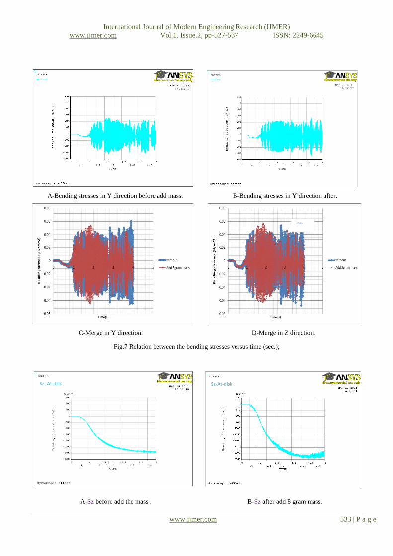
3.2.2 Behaviour of bending stresses with unbalance when add mass
We discover the relation between the bending stress versus
time(second),see Fig.(7–A,B),the performance of bending
stresses at gyroscopic effect in the middle when add 8 gram
mass in the disc at phase angles of Ø=90° and Ø=270
°
respectively.
The bending stresse decreases in both direction of motion
(Y, Z),see Fig (7-C,D) that mean reduce the reaction force in
the bearing to make the bearing long save life.
Time (s)
Dis
pla
cem
ent
(m)
Page 7
International Journal of Modern Engineering Research (IJMER)
www.ijmer.com Vol.1, Issue.2, pp-527-537 ISSN: 2249-6645
www.ijmer.com 533 | P a g e
A-Bending stresses in Y direction before add mass. B-Bending stresses in Y direction after.
C-Merge in Y direction. D-Merge in Z direction.
Fig.7 Relation between the bending stresses versus time (sec.);
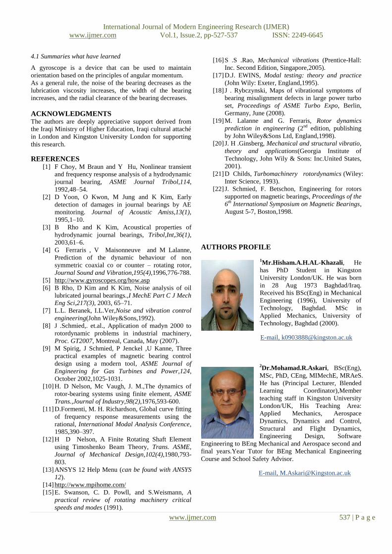
A-Sz before add the mass . B-Sz after add 8 gram mass.
UZdisk
Sz -At-disk
Sz-At-disk
Page 8
International Journal of Modern Engineering Research (IJMER)
www.ijmer.com Vol.1, Issue.2, pp-527-537 ISSN: 2249-6645
www.ijmer.com 534 | P a g e
C- Sy –Sz at disc.
Fig.8 Bending stresses sample in Y and Z direction (gyroscopic effect);
3.3 Discover damping ratio(ζ) from modal analysis
We discover the damping ratio (ζ) for different mode shape
by cur fitting [11,18&19], (multi degree of freedom system)
in experimental part, (Table 3) and see Fig.(9).
Table (3)
Natural frequency and damping ratio (ζ ) for gyroscopic effect rang (0-500) Hz,(experimental part).
Name
Natural Frequency
(Hz) Damping Ratio(ζ) % Modal A[kg/s]
Mode1 15.137 75.773 1.387959e-04 +i6.447278e-05
Mode 2 216.51 26.637 0.000103579 +i2.700067e-5
Fig. 9 Damping ratio(ζ ) versus natural frequency Fig 10.Variation of amplification ratio with r [16,20].
(0-500)Hz,gyroscopic effect.
0
10
20
30
40
50
60
70
80
0 50 100 150 200 250
Dam
pin
g R
atio
(ζ),
%
Natural Frequency(Hz)
Damping Ratio versus ,Natural frequency (0-500)Hz,Gyroscopic effect.
Damping Ratio versus .Natural frequency (0-500)Hz,Gyroscopic.
SY-SZ-At-disk
Page 9
International Journal of Modern Engineering Research (IJMER)
www.ijmer.com Vol.1, Issue.2, pp-527-537 ISSN: 2249-6645
www.ijmer.com 535 | P a g e
3.4 System identification and vibration monitoring in gyroscopic effect
Fig. 11 Gyroscopic effect,(FRF) versus frequency (Hz),(first mode shape).Natural frequency 15.137 Hz.
Fig.12 Gyroscopic effect,(FRF) versus Frequency (Hz),(second mode shape).Natural frequency 216.51Hz.
3.5 Contrast measured and predicted natural frequencies
for gyroscope
All the result nearby each other between the experimental
and simulation (ANSYS) for gyroscope without increasing
the speed, see the result in (Table 4) and Fig. (14) for
contrast.
Table (4)
Contrast between natural frequency (Hz),outcomes from experiment&ANSYS,(gyroscopic effect) at speed 30 rpm.
Mode Shape ωn (ANSYS)Gyroscopic (Hz)
Frequency Gyroscopic
Experiment(Hz) Error %
1 15.703 15.137 1.158007973
2 216.8 216.51 -0.133943005
Page 10
International Journal of Modern Engineering Research (IJMER)
www.ijmer.com Vol.1, Issue.2, pp-527-537 ISSN: 2249-6645
www.ijmer.com 536 | P a g e
Fig. 13 Mode shape number versus natural frequency
experiment and ANSYS,(gyroscopic effect).
Fig. 14 Natural frequency(experiment versus ANSYS),
(gyroscopic effect).
IV. DISCUSSION AND CONCLUSION In this paper investigate the behaviour of bearing rotor
system with gyroscopic effect has been cared out ,a simple
mathematical model has been used, however more elaborate
models based on a much large degree of freedom may be
used based on suppleness or stiffness influence coefficients.
The mathematical models may also be used to refine the
measured data and help in removal of contaminated data. It
is therefore feasible to create a mathematical model as a
database for various systems for condition monitoring
during their life time of the machines.
For further studies, there is no need to make more
experiments about this study while ANSYS gives accurate
results. We used (ANSYS) to find the relation between the
reaction bearing forces (N) with respect time can we see
Fig.(5-A,B,C&D).This performance in the right and left
bearings with different speed we see when increasing speed
of rotation the reaction force increasing for both right and
left bearings when increasing the speed of rotation but from
the figure above we see the maximum reaction force in Y
direction in left and right bearings when the motor run up,
after a few second is become decreases. While the reaction
forces in Z direction is began increasing slowly in left and
right bearings until reach maximum value when the speed is
increasing.That mean we must take care to left bearing when
run up the motor because this bearing carry maximum
reaction force at the began.During study this performance of
reaction force in both bearings can aid in the design of low-
noise rotor-bearing systems and reduce the reaction force in
the bearing to make the bearings long save life by
lubracation.In order to investigate the effects of design
parameters on the noise of rotor-bearing systems, the effects
of radial clearance and width of bearing, lubricant viscosity,
for various rotational speeds. It is found that, as a general
rule, the noise of the bearing decreases as the lubrication
viscosity increases, the width of the bearing increases, and
the radial clearance of the bearing decreases.
The locations of the adding balance masses in suppressing
the vibration amplitudes are decided to be at the optimum
phase angles of Ø=90° and Ø=270
° respectively.It was
observed for each of the different eccentricity ratios studies.
The critical adding mass ratios can also be predicted through
its linear relationship with the eccentricity ratios,The
simulation values obtained from the ANSYS see Fig.(6),
this results showed that could reduce the vibration by
reducing amplitude when add 8 gram mass in the angles
show above; As a result, can reduce the vibration more
effectively and modified method described in this paper to
solve real-world engineering problems.
We discover the relation between the bending stress versus
time(second),see Fig. (7) the behavior of bending stresses at
gyroscopic effect when added 8 gram mass in the disc the
bending stresse decreases in both direction of motion (Y,Z)
that mean reduce the reaction force in the bearing to make
the bearing long and save life .
From Table (3) detection damping ration (ζ) in experimental
part for the first and second mode at speed 30 rpm, and we
can see from Fig (9) the decreased the damping ratio caused
increased natural frequency until reach maximum amplitude
when the system reach resonance 𝛚 = 𝛚n, when damping
ration (ζ) approximately = 0),(free vibration) is clear in
Fig.(10)[16,21].
From Table(4),contrast measured and predicted natural
frequencies for gyroscopic effect all the outcome nearby
each other between the experimental shown in Fig.(11),(12)
and model simulation (ANSYS) shown in Fig.(3),(4)for
gyroscopic effect without rising the speed,see the result in
(Table 4) and is more clear in Fig. (13)&(14) for contrast.
Plotting the experimental value against the predicted on for
each of the modes included in the contrast shown in
Fig.(14).In this way it is possible to see not only the degree
of correlation between the two sets of results, but also the
nature(and possible case) of any discrepancies which do
exist.The points plotted should lie on or close to straight line
of slope [17,22].
0
0.5
1
1.5
2
2.5
0 50 100 150 200 250
Mo
de
sh
ape
nu
mb
er
Natural Frequency(Hz)
Mode shape Number versus Natural Frequency rang(0-500)Hz,Gyroscopic effect,
ωn (ANSYS)Gyroscopic (Hz)
Frequency Gyroscopic Experiment(Hz)
0
50
100
150
200
250
0 50 100 150 200 250
Expe
rim
enta
l nat
ural
fre
qunc
y,(H
z)
Predicted Natural frequency,(ANSYS),(Hz)
contrast experimental & predicted natural frequency(Hz)
Page 11
International Journal of Modern Engineering Research (IJMER)
www.ijmer.com Vol.1, Issue.2, pp-527-537 ISSN: 2249-6645
www.ijmer.com 537 | P a g e
4.1 Summaries what have learned
A gyroscope is a device that can be used to maintain
orientation based on the principles of angular momentum.
As a general rule, the noise of the bearing decreases as the
lubrication viscosity increases, the width of the bearing
increases, and the radial clearance of the bearing decreases.
ACKNOWLEDGMENTS The authors are deeply appreciative support derived from
the Iraqi Ministry of Higher Education, Iraqi cultural attaché
in London and Kingston University London for supporting
this research.
REFERENCES [1] F Choy, M Braun and Y Hu, Nonlinear transient
and frequency response analysis of a hydrodynamic
journal bearing, ASME Journal Tribol,114,
1992,48–54.
[2] D Yoon, O Kwon, M Jung and K Kim, Early
detection of damages in journal bearings by AE
monitoring. Journal of Acoustic Amiss,13(1),
1995,1–10.
[3] B Rho and K Kim, Acoustical properties of
hydrodynamic journal bearings, Tribol,Int,36(1),
2003,61–6.
[4] G Ferraris , V Maisonneuve and M Lalanne,
Prediction of the dynamic behaviour of non
symmetric coaxial co or counter – rotating rotor,
Journal Sound and Vibration,195(4),1996,776-788.
[5] http://www.gyroscopes.org/how.asp
[6] B Rho, D Kim and K Kim, Noise analysis of oil
lubricated journal bearings.,I MechE Part C J Mech
Eng Sci,217(3), 2003, 65–71.
[7] L.L. Beranek, I.L.Ver,Noise and vibration control
engineering(John Wiley&Sons,1992).
[8] J .Schmied,. et.al., Application of madyn 2000 to
rotordynamic problems in industrial machinery,
Proc. GT2007, Montreal, Canada, May (2007).
[9] M Spirig, J Schmied, P Jenckel ,U Kanne, Three
practical examples of magnetic bearing control
design using a modern tool, ASME Journal of
Engineering for Gas Turbines and Power,124,
October 2002,1025-1031.
[10] H. D Nelson, Mc Vaugh, J. M.,The dynamics of
rotor-bearing systems using finite element, ASME
Trans.,Journal of Industry,98(2),1976,593-600.
[11] D.Formenti, M. H. Richardson, Global curve fitting
of frequency response measurements using the
rational, International Modal Analysis Conference,
1985,390–397.
[12] H D Nelson, A Finite Rotating Shaft Element
using Timoshenko Beam Theory, Trans. ASME,
Journal of Mechanical Design,102(4),1980,793-
803.
[13] ANSYS 12 Help Menu (can be found with ANSYS
12).
[14] http://www.mpihome.com/
[15] E. Swanson, C. D. Powll, and S.Weismann, A
practical review of rotating machinery critical
speeds and modes (1991).
[16] S .S .Rao, Mechanical vibrations (Prentice-Hall:
Inc. Second Edition, Singapore,2005).
[17] D.J. EWINS, Modal testing: theory and practice
(John Wily: Exeter, England,1995).
[18] J . Rybczynski, Maps of vibrational symptoms of
bearing misalignment defects in large power turbo
set, Proceedings of ASME Turbo Expo, Berlin,
Germany, June (2008).
[19] M. Lalanne and G. Ferraris, Rotor dynamics
prediction in engineering (2nd
edition, publishing
by John Wiley&Sons Ltd, England,1998).
[20] J. H .Ginsberg, Mechanical and structural vibratio,
theory and applications(Georgia Institute of
Technology, John Wily & Sons: Inc.United States,
2001).
[21] D Childs, Turbomachinery rotordynamics (Wiley:
Inter Science, 1993).
[22] J. Schmied, F. Betschon, Engineering for rotors
supported on magnetic bearings, Proceedings of the
6th
International Symposium on Magnetic Bearings,
August 5-7, Boston,1998.
AUTHORS PROFILE
1Mr.Hisham.A.H.AL-Khazali, He
has PhD Student in Kingston
University London/UK. He was born
in 28 Aug 1973 Baghdad/Iraq.
Received his BSc(Eng) in Mechanical
Engineering (1996), University of
Technology, Baghdad. MSc in
Applied Mechanics, University of
Technology, Baghdad (2000).
E-mail, [email protected]
2Dr.Mohamad.R.Askari, BSc(Eng),
MSc, PhD, CEng, MIMechE, MRAeS.
He has (Principal Lecturer, Blended
Learning Coordinator),Member
teaching staff in Kingston University
London/UK, His Teaching Area:
Applied Mechanics, Aerospace
Dynamics, Dynamics and Control,
Structural and Flight Dynamics,
Engineering Design, Software
Engineering to BEng Mechanical and Aerospace second and
final years.Year Tutor for BEng Mechanical Engineering
Course and School Safety Advisor.
E-mail, [email protected]