33
DK2 Handel-C and PSL basics

DK2
Handel-C and PSL basics

Handel-C and PSL basics
www.celoxica.com
Celoxica, the Celoxica logo and Handel-C are trademarks of Celoxica Limited.
All other products or services mentioned herein may be trademarks of their respective owners.
Neither the whole nor any part of the information contained in, or the product described in, this document may be adapted or reproduced in any material form except with the prior written permission of the copyright holder.
The product described in this document is subject to continuous development and improvement. All particulars of the product and its use contained in this document are given by Celoxica Limited in good faith. However, all warranties implied or express, including but not limited to implied warranties of merchantability, or fitness for purpose, are excluded.
This document is intended only to assist the reader in the use of the product. Celoxica Limited shall not be liable for any loss or damage arising from the use of any information in this document, or any incorrect use of the product.
The information contained herein is subject to change without notice and is for general guidance only.
Copyright © 2003 Celoxica Limited. All rights reserved.
Authors: SB
Document number: 1
Customer Support at http://www.celoxica.com/support/
Celoxica in Europe Celoxica in Japan Celoxica in Asia Pacific Celoxica in the Americas
T: +44 (0) 1235 863 656 T: +81 (0) 45 331 0218 T: +65 6896 4838 T: +1 800 570 7004
E: [email protected] E: [email protected] E: [email protected] E: [email protected]

Handel-C and PSL basics
www.celoxica.com
Page 1
Contents
1 TUTORIAL: HANDEL-C AND PSL BASICS ............................................... 3
2 HANDEL-C BASICS: PLATFORM SUPPORT LIBRARY .................................. 4
3 HANDEL-C BASICS: PLATFORM ABSTRACTION LAYER ............................... 4
4 SEVEN-SEGMENT DEVICE DRIVER ......................................................... 6 4.1 HARDWARE INTERFACE ................................................................ 6 4.2 SOURCE FILE ORGANIZATION AND EXAMPLE PROJECT .......................... 7
5 SETTING UP A PAL WORKSPACE.......................................................... 9 5.1 SEVEN-SEGMENT PROJECT IN PAL................................................ 15
6 HANDEL-C LANGUAGE BASICS........................................................... 17 6.1 HARDWARE IMPLEMENTATION OF EXAMPLES ................................... 17 6.2 USE OF PARALLEL CODE.............................................................. 18
6.2.1 Swapping variable values........................................................................ 20 6.3 CHANNEL COMMUNICATIONS ....................................................... 21 6.4 BIT MANIPULATION EXAMPLES..................................................... 24
6.4.1 Drop operator........................................................................................ 24 6.4.2 Take operator........................................................................................ 25 6.4.3 Select operator ...................................................................................... 26 6.4.4 Concatenate operator ............................................................................. 27
6.5 USING SIGNALS ....................................................................... 28
7 INDEX......................................................................................... 31

Handel-C and PSL basics
www.celoxica.com
Conventions A number of conventions are used in this document. These conventions are detailed below.
Warning Message. These messages warn you that actions may damage your hardware.
Handy Note. These messages draw your attention to crucial pieces of information.
Hexadecimal numbers will appear throughout this document. The convention used is that of prefixing the number with '0x' in common with standard C syntax.
Sections of code or commands that you must type are given in typewriter font like this: void main();
Information about a type of object you must specify is given in italics like this: copy SourceFileName DestinationFileName
Optional elements are enclosed in square brackets like this: struct [type_Name]
Curly brackets around an element show that it is optional but it may be repeated any number of times. string ::= "{character}"

Handel-C and PSL basics
www.celoxica.com
Page 3
1 Tutorial: Handel-C and PSL basics The following examples illustrate basic use of the common Handel-C operators which are not present in C or C++. The first example involves creating a driver for an off-chip peripheral, and uses the Celoxica PSL API for this. A brief overview of PSL and PAL is also given, for further information consult the relevant manuals and tutorial guides. Later examples use the Celoxica PAL API, allowing them to be used in simulation as well as with any supported board. The examples given can be used with any FPGA based board, but are shown configured for the Celoxica RC200.
New users are recommended to work through the following topics in order:
Platform Support Library (see page 4)
Seven-segment device driver (see page 6)
Setting up a PAL workspace (see page 9)
Handel-C language basics (see page 17)

Handel-C and PSL basics
www.celoxica.com
Page 4
2 Handel-C basics: Platform Support Library
A Platform Support Library (PSL) is a Handel-C library containing functions for communicating with peripheral devices on an FPGA/PLD platform. A collection of functions for a particular device is referred to as a device driver. This document describes techniques and considerations for implementing device drivers in Handel-C, and thereby creating a PSL.
A device driver has two interfaces, one for the device and one for the application programmer. The device interface is defined by the device manufacturer, whereas the Application Programmers Interface (API) is defined by the author of the device driver. Where possible, a device driver presents an API which is less complex than the device interface by encapsulating device command timing and command sequences.
SYSTEM HIERARCHY
3 Handel-C basics: Platform Abstraction Layer
The functions presented in a device driver API reflect the characteristics of the device. For example, an API function which reads data from a device will return data of a specific bit-width that corresponds to that device. Different devices that achieve the same purpose but have different characteristics (such as data width) will have APIs that reflect these differences.

Handel-C and PSL basics
www.celoxica.com
Page 5
Celoxica’s Platform Abstraction Layer (PAL) offers a way to abstract over the differences in device driver APIs. PAL sits between the application and the device driver layer and translates calls to functions in the PAL API into the calls in the device drivers API.
SYSTEM HIERARCHY WITH PAL
PAL performs generalization of device driver APIs with auxiliary functions that can report the device characteristics from within an application. For example, there are PAL functions for determining the data width of a resource.
When you write a device driver you should make the API specific to the device and then use PAL to make the device driver compatible with existing portable applications.

Handel-C and PSL basics
www.celoxica.com
Page 6
4 Seven-segment device driver A device driver for a seven-segment display provides control of the display state. It is possible to write a raw shape to the display, or a digit which will be interpreted by the driver to display the correct shape. The source code for the driver should be in a separate .hcc file, with a .hch header file containing prototypes for the API. These files can then be used directly in a project, or compiled into a library.
BLOCK DIAGRAM
4.1 Hardware interface
First define macro expressions for the pins which the seven-segment displays are connected to. The example shown is for the RC200:
static macro expr SevenSeg0Pins = {"L5", "G4", "F3", "K3", "L4", "L3", "H4", "G3"}; static macro expr SevenSeg1Pins = {"K4", "G5", "H3", "L6", "F5", "H5", "J3", "J4"};
Now define registers to hold the values to be displayed, initialising them to zero. The example shown is for the RC200, which has two seven-segment displays, hence the array of two 8-bit unsigned integers.
static unsigned 8 SevenSeg[2] = {0, 0};
Now define a Handel-C interface to attach the pins to the variables. Use the Handel-C bus_out interface as the pins are outputs from the device driver.
static interface bus_out () SevenSeg0Out (SevenSeg[0]) with {data = SevenSeg0Pins}; static interface bus_out () SevenSeg1Out (SevenSeg[1]) with {data = SevenSeg1Pins};
Note that making the SevenSeg variable and the various macros static prevents them from being visible outside the file they are defined in.

Handel-C and PSL basics
www.celoxica.com
Page 7
Now implement a macro procedure to display a ‘shape’ on the seven-segment display. The figure below shows how the segments of the display are numbered, so that when an 8-bit data value is written to the display, bit 0 is the top segment, and bit 7 is the decimal point.
macro proc SevenSeg0WriteShape (Shape) { SevenSeg[0] = Shape; }
NUMBERING OF DISPLAY SEGMENTS
Now implement a macro procedure which accepts a 4-bit unsigned integer and displays the corresponding hexadecimal digit on the seven-segment display. The decimal point is set according to a further 1-bit unsigned integer parameter. The required shapes to display hexadecimal digits have been provided in the ROM TranslationROM0 in the example project (TutorialSevenSeg1).
macro proc SevenSeg0WriteDigit (Value, DecimalPoint) { SevenSeg[0] = DecimalPoint @ TranslationROM0[Value]; }
The two macros shown for displaying a shape and a digit are for a single seven-segment display, and a further copy of each will be required for each additional display.
4.2 Source file organization and example project
To allow the driver for the seven segment display to be easily included in a library, as part of a PSL for a board, the source code should be organized in a certain way. All the Handel-C source code for interfacing to the hardware should be in a single file, and the prototypes for the macros should be in a separate header file. By doing this the header and source file can be included directly in projects during their development, and later

Handel-C and PSL basics
www.celoxica.com
Page 8
the Handel-C file can be linked into a PSL library, and the prototypes for the macros pasted into the PSL library header.
There as an example workspace set up in TutorialSevenSeg1, which contains a library project with the seven segment code in it, with the interface pins set up for the Celoxica RC200 board. There is also an example project using the library, again set up for the RC200.

Handel-C and PSL basics
www.celoxica.com
Page 9
5 Setting up a PAL workspace Rather than using the seven-segment PSL driver (see page 6), the tutorial will continue using the standard PAL seven-segment displays instead. This will allow a range of boards to be used with the tutorial, and also simulation using the PAL Virtual Platform. Each platform which is going to be supported can have its own configuration created in DK, to allow easy customization.
First, select the File->New menu and create a new workspace, as shown below.
CREATING A NEW WORKSPACE
Then, select the File->New menu again and create a new project in the workspace, as shown below. If you are targeting a board, the chip type must be set correctly – the

Handel-C and PSL basics
www.celoxica.com
Page 10
figure below shows the setting for the Celoxica RC200. For simulation, the chip type is irrelevant.
CREATING A NEW PROJECT

Handel-C and PSL basics
www.celoxica.com
Page 11
Now, select the Build->Configurations menu, select the Debug configuration, and click the Add button. A dialog box will appear, where a new configuration name can be entered, and settings copied from an existing configuration. Create a new configuration called Sim, based on the existing Debug configuration, as shown below. Also create a configuration called RC200, based on the existing EDIF configuration.
CREATING A NEW CONFIGURATION

Handel-C and PSL basics
www.celoxica.com
Page 12
The two new configurations can now be customized for their particular targets. Select the Project->Settings menu, and from the Settings for drop-down, select the newly created Sim configuration. On the General tab, change the output directories to match the configuration name – Sim in this case, as shown below.
SETTING OUTPUT DIRECTORIES

Handel-C and PSL basics
www.celoxica.com
Page 13
On the Preprocessor tab, add USE_SIM to the Preprocessor definitions box, as shown below. This definition is used to specify which PAL target is to be used for this configuration.
SETTING PREPROCESSOR DEFINITIONS
The final step in setting up the new configuration is to go to the Linker tab in the Project Settings, and add libraries which are required for PAL. For simulation the target is the PalSim Virtual Platform, which requires the Handel-C libraries sim.hcl and pal_sim.hcl to be added. The C++ library palSim.lib is also required, and must be included explicitly in the Additional C/C++ Modules box. It is possible to browse to locate the C++ module, the default path would be:

Handel-C and PSL basics
www.celoxica.com
Page 14
C:\program files\celoxica\pdk\software\lib\palsim.lib The Linker tab with all the libraries set up for simulation is show below.
LINKER SETTINGS FOR SIMULATION

Handel-C and PSL basics
www.celoxica.com
Page 15
The RC200 configuration must also be set up in a similar way, but the preprocessor definition should be USE_RC200, and the included Handel-C libraries should be rc200.hcl and pal_rc200.hcl. The Technology Mapper should also be enabled, as it allows DK to produce faster circuits. No C++ modules are required to be linked in. As the RC200 is a hardware target, a device type must also be specified. Go to the Chip tab in Project Settings, make sure that Family is set to Xilinx Virtex-II, and the Part is set to XC2V1000-4-FG456, as shown below.
CHIP TYPE SETTINGS FOR RC200
5.1 Seven-segment project in PAL
To use PAL in a project, a target clock rate must be set and the pal_master.hch header file must be included, as shown below. For the seven-segment examples, the clock rate is not very important – a value of 20MHz has been set here.
#define PAL_TARGET_CLOCK_RATE 20000000 #include "pal_master.hch"
At the start of the project’s main function, calls should be made to specify what version of PAL is required, and what resources we need to be available. For the seven-segment tutorials we want to use two seven-segment displays, so the required code is as shown below: PalVersionRequire (1, 2); // require PAL v1.2 or later PalSevenSegRequire (2); // require two seven-segment displays
Before writing data to the seven-segment displays, they must be enabled using the PalSevenSegEnable macro. The parameter to this macro should be a call to the

Handel-C and PSL basics
www.celoxica.com
Page 16
PalSevenSegCT macro, which itself should be passed a number to index into the requested number of displays, as shown below:
PalSevenSegEnable (PalSevenSegCT (0)); PalSevenSegEnable (PalSevenSegCT (1));
After enabling the displays, data can be written to them, again using calls to PalSevenSegCT with an index to identify which display to send the data to, as shown below:
PalSevenSegWriteDigit (PalSevenSegCT (0), (unsigned 4) 0xE, 0); PalSevenSegWriteShape (PalSevenSegCT (1), (unsigned 8) 0b11110110);
The TutorialSevenSeg2 workspace has this code in it, set up for Sim and RC200.

Handel-C and PSL basics
www.celoxica.com
Page 17
6 Handel-C language basics The following sections use the PAL seven-segment workspace described above to illustrate the use of some of the Handel-C language operators and constructs which are not present in C or C++. The TutorialHCBasics workspace contains the code for this section of the tutorial. Below is a list of the example projects in this section of the tutorial:
Use of parallel code: ParExample
Channel communication: ChanCount, ChanCircle
Bit manipulation: DropExample, TakeExample, SelectExample, CatExample
Use of signals: SignalExample
6.1 Hardware implementation of examples
The examples in the Seven-segment device driver (see page 6) and the Seven-segment project in PAL (see page 15) only wrote static data to the seven-segment displays, but the following examples are going to display continuously changing data. Because the hardware version will be running at tens of MHz, and can not be paused, it will be necessary to slow down some parts of the program so its operation can be observed. To do this the macro shown below will be used. As it uses a call to log2ceil(), the stdlib.hch header file must be included, and the stdlib.hcl library added to the Linker tab in the Project Settings.
/* * Sleep for "n" milliseconds */ static macro proc Sleep (Milliseconds) { macro expr Cycles = (PAL_ACTUAL_CLOCK_RATE * Milliseconds) / 1000; unsigned (log2ceil (Cycles)) Count; Count = 0; do { Count++; } while (Count != Cycles - 1); }

Handel-C and PSL basics
www.celoxica.com
Page 18
This macro will not be required in simulation, as it will be possible to single-cycle step through the code, so a #ifndef will be used, as shown below:
#ifndef SIMULATE Sleep (500); #endif
6.2 Use of parallel code
par{} is one of the key Handel-C constructs used to improve the performance of a program. It executes multiple code blocks in parallel. The seq{} construct is used to explicitly execute code sequentially, instead of in parallel. Sequential execution is the default if neither par{} or seq{} is specified.
The ParExample project in the TutorialHCBasics workspace runs two counters (Count and Circle) in parallel. They cycle from 0 to 15 and 0 to 5 respectively. Count is displayed on one of the seven-segment displays, while Circle is used to index the ROM CircleDisplayEncode, which contains the appropriate values to display a lit segment moving around a display. The declaration of the variables is shown below:
static rom unsigned 8 CircleDisplayEncode[6] = {0x1,0x2,0x4,0x8,0x10}; unsigned 4 Count; unsigned 3 Circle;
After calling the required PAL functions to request and initialize the seven-segment displays, the Count and Circle variables are initialized to zero, and the following loop is executed forever:

Handel-C and PSL basics
www.celoxica.com
Page 19
while (1) { /* * Run the two displays in parallel */ par { seq { /* * Increment up to 15, then wrap round to 0 */ Count++; /* * Write Count to display */ PalSevenSegWriteDigit (PalSevenSegCT (0), Count, 0); } seq { /* * Increment up to 5, then reset to 0 */ Circle = (Circle == 5) ? 0 : (Circle + 1); /* * Look up value in ROM, and set display */ PalSevenSegWriteShape (PalSevenSegCT (1), CircleDisplayEncode[Circle]); } } }
Each iteration of the while(1) loop takes two clock cycles to complete, as the par{} statement causes the two sequential code blocks within it to be executed in parallel. Without the use of par{}, the loop would take four clock cycles to execute.

Handel-C and PSL basics
www.celoxica.com
Page 20
The execution time can in fact be reduced to a single clock cycle by removing the seq{} from around the two code blocks, causing all four lines of code to be executed in parallel. This creates a simple two-stage pipeline, as in Handel-C values are only assigned to variables at the end of a clock cycle. Therefore the value displayed would be that held by the counter during the previous clock cycle.
Try executing the ParExample project in the TutorialHCBasics workspace in simulation, and changing the code to make each loop iteration take 1 or 4 clock cycles. Use the F11 key to step through the code one cycle at a time, and observe its behaviour. If the Variables Debug Window is open, and the Locals tab selected, the value of the variables in the project will be visible.
If an RC200 board is available, try compiling the project for it, and using the Xilinx Place & Route tools to create a bitfile to download to the board. Note that the call to Sleep() will now be active, slowing the program down in the hardware so it can be observed. The behaviour should be the same as that seen in simulation.
6.2.1 Swapping variable values
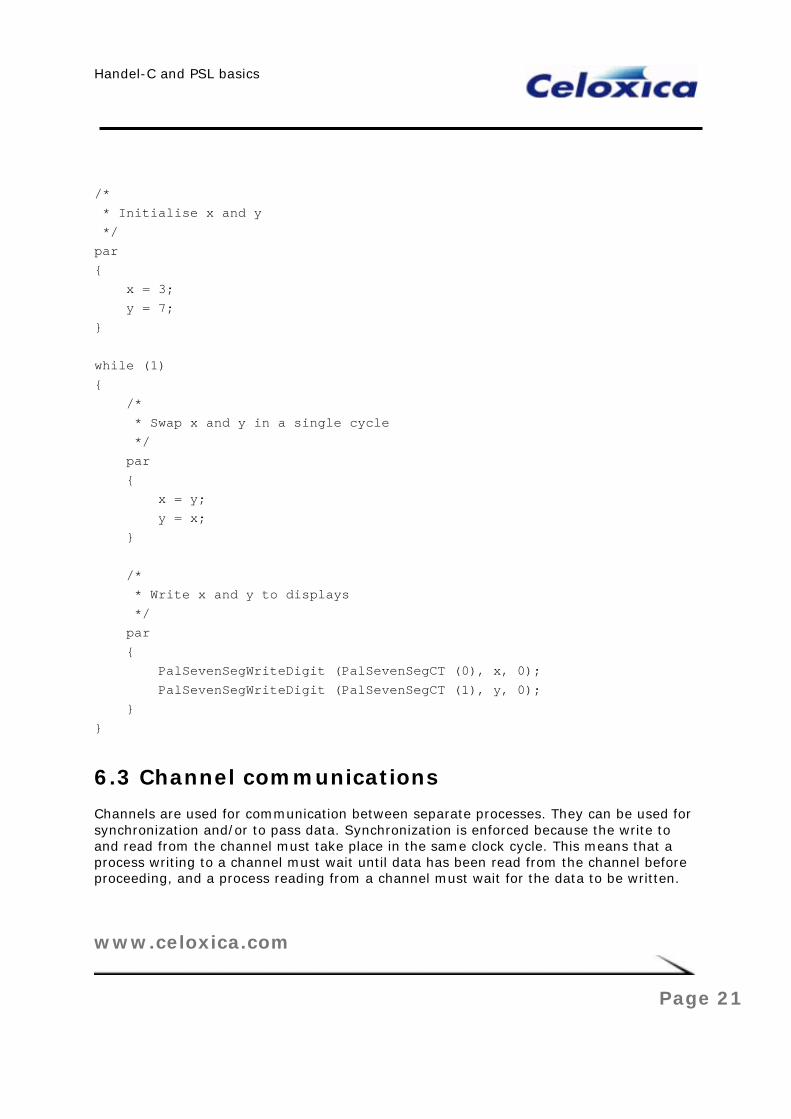
The SwapExample project in the TutorialHCBasics workspace shows how the values of two variables can be exchanged in a single clock cycle without using an intermediate location to store the contents of one of them. This is possible because a variable in Handel-C does not take on the value assigned to it until the end of a clock cycle. By assigning the value of each variable to the other in parallel, the contents are swapped in a single cycle, without any intermediate storage. The source code shown below assigns values to the variables and swaps them back and forth, displaying their values on the two 7-segment displays.
The main point of this demonstration is that it is impossible to achieve this behaviour using C with a conventional compiler.
Handel-C and PSL basics
www.celoxica.com
Page 21
/* * Initialise x and y */ par { x = 3; y = 7; } while (1) { /* * Swap x and y in a single cycle */ par { x = y; y = x; } /* * Write x and y to displays */ par { PalSevenSegWriteDigit (PalSevenSegCT (0), x, 0); PalSevenSegWriteDigit (PalSevenSegCT (1), y, 0); } }
6.3 Channel communications
Channels are used for communication between separate processes. They can be used for synchronization and/or to pass data. Synchronization is enforced because the write to and read from the channel must take place in the same clock cycle. This means that a process writing to a channel must wait until data has been read from the channel before proceeding, and a process reading from a channel must wait for the data to be written.

Handel-C and PSL basics
www.celoxica.com
Page 22
The ChannelExample project in the TutorialHCBasics workspace uses two processes, one counting a seven-segment display in hexadecimal, and the other circling a lit segment, as shown below.

Handel-C and PSL basics
www.celoxica.com
Page 23
par { while (1) { unsigned 1 Temp; do { par { Count++; PalSevenSegWriteDigit (PalSevenSegCT (0), Count, 0); } } while(Count != 0); CountChan ! 0; /* Write to one channel */ CircleChan ? Temp; /* Read from other channel */ } while (1) { unsigned 1 Temp; CountChan ? Temp; /* Read from one channel */ do { par { Circle++; PalSevenSegWriteShape (PalSevenSegCT (1), CircleDisplayEncode[Circle]); } } while(Circle != 6); Circle = 0; /* Reset Circle for next loop */ CircleChan ! 0; /* Write to other channel */ } }

Handel-C and PSL basics
www.celoxica.com
Page 24
The first process counts from 0x0 to 0xF on its display, writes to the CountChan channel, and then reads from the CircleChan channel, before counting again. The second process reads from the CountChan channel, circles a lit segment around the display, writes to the CircleChan channel, and then waits to read from the CountChan channel again.
The channels are only a single bit wide, and are used for synchronization rather than communication of data. The result is that the two 7-segment displays operate alternately, as the channel synchronization ensures that only one process can be executing its display loop at any time.
When a channel is read, it must be read into a variable, so the example uses Temp to receive the value coming from each of the channels. Because this variable is never read from, the optimizer in DK will be able to remove the hardware used by the variable during compilation.
The ChannelExample project in the TutorialHCBasics workspace is straightforward to run in hardware, but in simulation breakpoints must be set in each of the two parallel loops. This is necessary because otherwise the Debugger will continue to follow the thread it is currently in, and it will not be possible to step through the code in the other thread. By setting breakpoints on the Circle++ and Count++ lines, it will be possible to step through the code continuously, and see both displays operating cycle-by-cycle.
6.4 Bit manipulation examples
The following examples illustrate how to use the four Handel-C bit manipulation operators which are not used in C/C++.
6.4.1 Drop operator
The DropExample project in the TutorialHCBasics workspace shows how to use the drop bits \\ operator. The source code is shown below:

Handel-C and PSL basics
www.celoxica.com
Page 25
while (1) { par { /* * Increment up to 15, then wrap round to 0 */ Count++; /* * Write Count and Count \\ 1 to display */ PalSevenSegWriteDigit (PalSevenSegCT (0), Count, 0); PalSevenSegWriteDigit (PalSevenSegCT (1), adju( (Count \\ 1), 4), 0); } }
The \\ operator returns a value with the least n significant bits dropped.
The value of Count is shown on the first 7-segment display; the second display shows Count with the lowest bit dropped. The adju() macro (from the Standard Library) is used to adjust the width of the modified value of Count to four bits, as this is the width required to be passed to PalSevenSegWriteDigit(). The example uses Count \\ 1 to drop a single bit, so while the first display counts from 0 to 0xF, the second counts from 0 to 7, but at half the rate, as shown in Table 1.
Count 0000 0001 0010 0011 0100 0101 0110 0111 1000 1001 1010 1011 1100 1101 1110 1111
Display 1 0 1 2 3 4 5 6 7 8 9 A B C D E F
Count \\ 1 000 000 001 001 010 010 011 011 100 100 101 101 110 110 111 111
Display 2 0 0 1 1 2 2 3 3 4 4 5 5 6 6 7 7
DROP EXAMPLE DISPLAYS
6.4.2 Take operator
The TakeExample project in the TutorialHCBasics workspace shows how to use the take bits <- operator. The source code is shown below:

Handel-C and PSL basics
www.celoxica.com
Page 26
while (1) { par { /* * Increment up to 15, then wrap round to 0 */ Count++; /* * Write Count and Count <- 3 to display */ PalSevenSegWriteDigit (PalSevenSegCT (0), Count, 0); PalSevenSegWriteDigit (PalSevenSegCT (1), adju( (Count <- 3), 4), 0); } }
The <- operator returns the n least significant bits from its operand.
The value of Count is shown on the first 7-segment display, while the second display shows the value of the lowest three bits of Count. The adju() macro is used to adjust the width of the modified value of count to four bits, as this is the width required to be passed to PalSevenSegWriteDigit(). The example uses Count <- 3 to take the lowest 3 bits, so while the first display counts once from 0 to 0xF, the second counts twice from 0 to 7, as shown in the table below.
Count 0000 0001 0010 0011 0100 0101 0110 0111 1000 1001 1010 1011 1100 1101 1110 1111
Display 1 0 1 2 3 4 5 6 7 8 9 A B C D E F
Count<-3 000 001 010 011 100 101 110 111 000 001 010 011 100 101 110 111
Display 2 0 1 2 3 4 5 6 7 0 1 2 3 4 5 6 7
TAKE EXAMPLE DISPLAYS
6.4.3 Select operator
The SelectExample project in the TutorialHCBasics workspace shows how to use the select bits [m:n] operator. The source code is shown below:

Handel-C and PSL basics
www.celoxica.com
Page 27
while (1) { par { /* * Increment up to 15, then wrap round to 0 */ Count++; /* * Write Count and Count[2:1] to display */ PalSevenSegWriteDigit (PalSevenSegCT (0), Count, 0); PalSevenSegWriteDigit (PalSevenSegCT (1), adju( (Count[2:1]), 4), 0); } }
The [m:n] operator returns bits m to n from its operand.
The value of Count is shown on the first 7-segment display, while the second display shows the value of the middle two bits of Count. The adju() macro is used to adjust the width of the modified value of count to four bits, as this is the width required to be passed to PalSevenSegWriteDigit(). The example uses Count[2:1] to select the middle two of four bits, so while the first display counts once from 0 to 0xF, the second counts twice from 0 to 3 at half the rate, as shown in the table below.
Count 0000 0001 0010 0011 0100 0101 0110 0111 1000 1001 1010 1011 1100 1101 1110 1111
Display 1 0 1 2 3 4 5 6 7 8 9 A B C D E F
Count[2:1] 00 00 01 01 10 10 11 11 00 00 01 01 10 10 11 11
Display 2 0 0 1 1 2 2 3 3 0 0 1 1 2 2 3 3
SELECT EXAMPLE DISPLAY VALUES
6.4.4 Concatenate operator
The CatExample project in the TutorialHCBasics workspace shows how to use the concatenate bits @ operator. The source code is shown below:

Handel-C and PSL basics
www.celoxica.com
Page 28
while (1) { par { /* * Increment up to 15, then wrap round to 0 */ Count++; /* * Write Count and (Count[2:0] @ 0) to display */ PalSevenSegWriteDigit (PalSevenSegCT (0), Count, 0); PalSevenSegWriteDigit (PalSevenSegCT (1), Count[2:0] @ 0, 0); } }
The @ operator joins together two operands to form a result whose width is equal to the sum of the operand widths. In this case that means the adju() macro does not need to be called, as three bits are selected from Count, and DK will infer that the concatenated zero should be one bit wide, giving the required total of four bits.
The value of Count is shown on the first 7-segment display, while the second display shows the value of the low three bits of Count with zero concatenated at the right. The result is that while the first display counts once from 0 to 0xF, the second counts 0, 2, 4, 6, 8, A, C, E twice, as shown in the table below.
Count 0000 0001 0010 0011 0100 0101 0110 0111 1000 1001 1010 1011 1100 1101 1110 1111
Display 1 0 1 2 3 4 5 6 7 8 9 A B C D E F
Count[2:0]@0 0000 0010 0100 0110 1000 1010 1100 1110 0000 0010 0100 0110 1000 1010 1100 1110
Display 2 0 2 4 6 8 A C E 0 2 4 6 8 A C E
CONCATENATE EXAMPLE DISPLAY VALUES
6.5 Using signals
Signal variables can be assigned to and read from in the same clock cycle. They hold their value ONLY for that clock cycle.
The source code for the example shown below sets a signal equal to the value of Count1 + 1, then uses this signal in two separate places, to set counters used to drive the two 7-

Handel-C and PSL basics
www.celoxica.com
Page 29
segment displays. Although this example is very simple, it illustrates how signals can be used to eliminate common sub-expressions, and make code more readable.
unsigned 4 Count1; unsigned 4 Count2; unsigned 4 Count3; signal <unsigned 4> CountSig; while (1) { /* * Increment up to 15, then wrap round to 0 */ Count1++; par { CountSig = Count1 * 2; /* Assign value to the signal, */ Count2 = CountSig; /* use the value from the signal */ Count3 = CountSig + 1; /* and use it again here */ } /* * Write Count2 and Count3 to display */ PalSevenSegWriteDigit (PalSevenSegCT (0), Count2, 0); PalSevenSegWriteDigit (PalSevenSegCT (1), Count3, 0); }


Handel-C and PSL basics
www.celoxica.com
Page 31
7 Index C
channels......................................... 21
concatenate .................................... 27
D
drop .............................................. 24
P
PAL.................................................. 9
par ................................................ 18
parallelism...................................... 18
S
select............................................. 26
seven segment display..............6, 7, 15
signals ........................................... 28
T
take............................................... 25
W
workspace ........................................ 9


