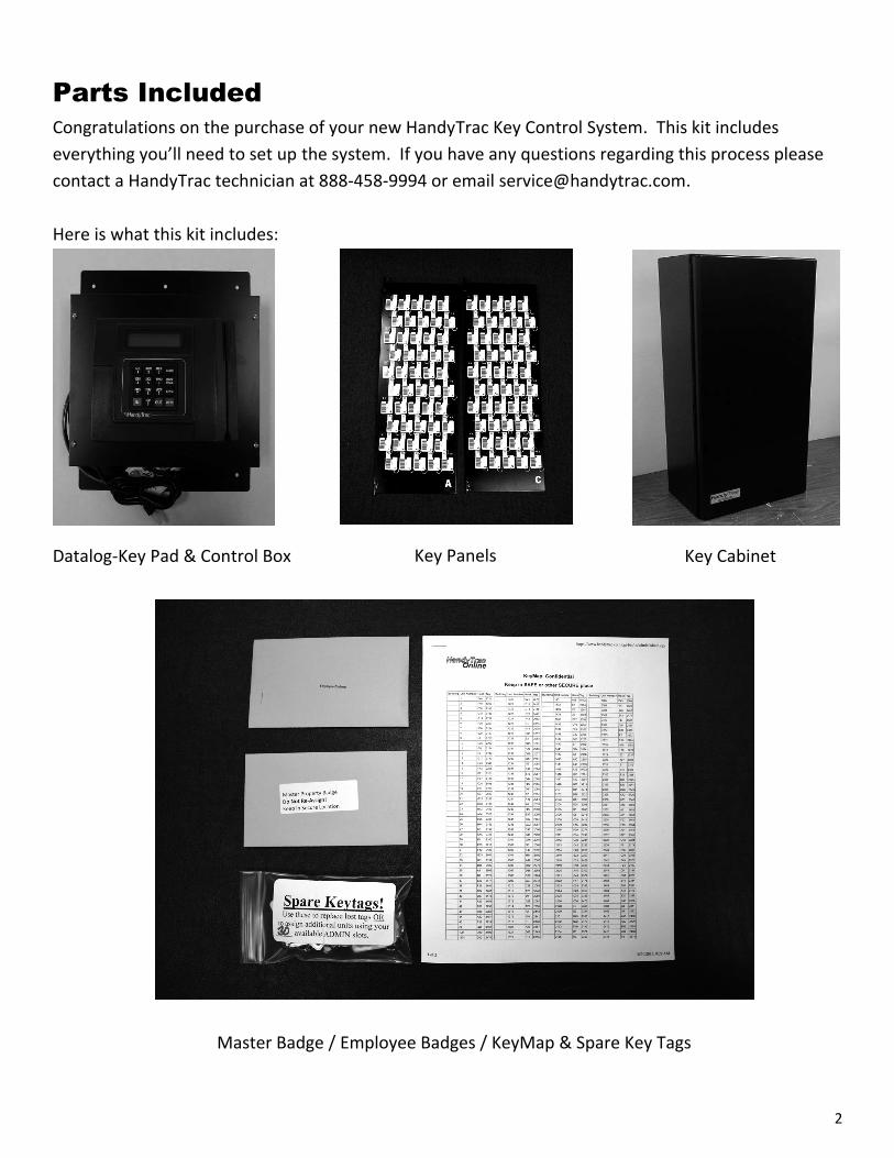
HT Scan 2.0 HandyTrac EASY GUIDE Installation and Operation 888-458-9994 www.handytrac.com [email protected]Dallas 16990 North Dallas Parkway Suite 206 Dallas, TX 75248 Toll Free: 800.665.9994 Fax: 972.380.9978 Atlanta 510 Staghorn Court Alpharetta, GA 30004 Toll Free: 800.665.9994 Fax: 678.990.2311 INSTALLATION Parts include ....................................................... 2 What you need .................................................... 3 Mounting cabinet & checking door alignment ...... 4 Mounting control box & key panels...................... 5 Double cabinet setup ........................................ 6-7 PREPARING FOR SET UP Establishing communications ............................... 8 Activating System................................................ 9 Moving keys into System ..................................... 9 OPERATION HandyTrac.com .............................................10-11 Accessing the system ......................................... 12 Programming fingerprints (biometric equipped). 12 Pulling a key ...................................................... 13 Using building pull ............................................. 13 Work order number key pull .............................. 14 Returning a key ................................................. 15 Review keys out ................................................ 15 Show last transaction ........................................ 15 Edit key tag ....................................................... 16 Change APT/UNIT.............................................. 17 Activity codes .................................................... 18
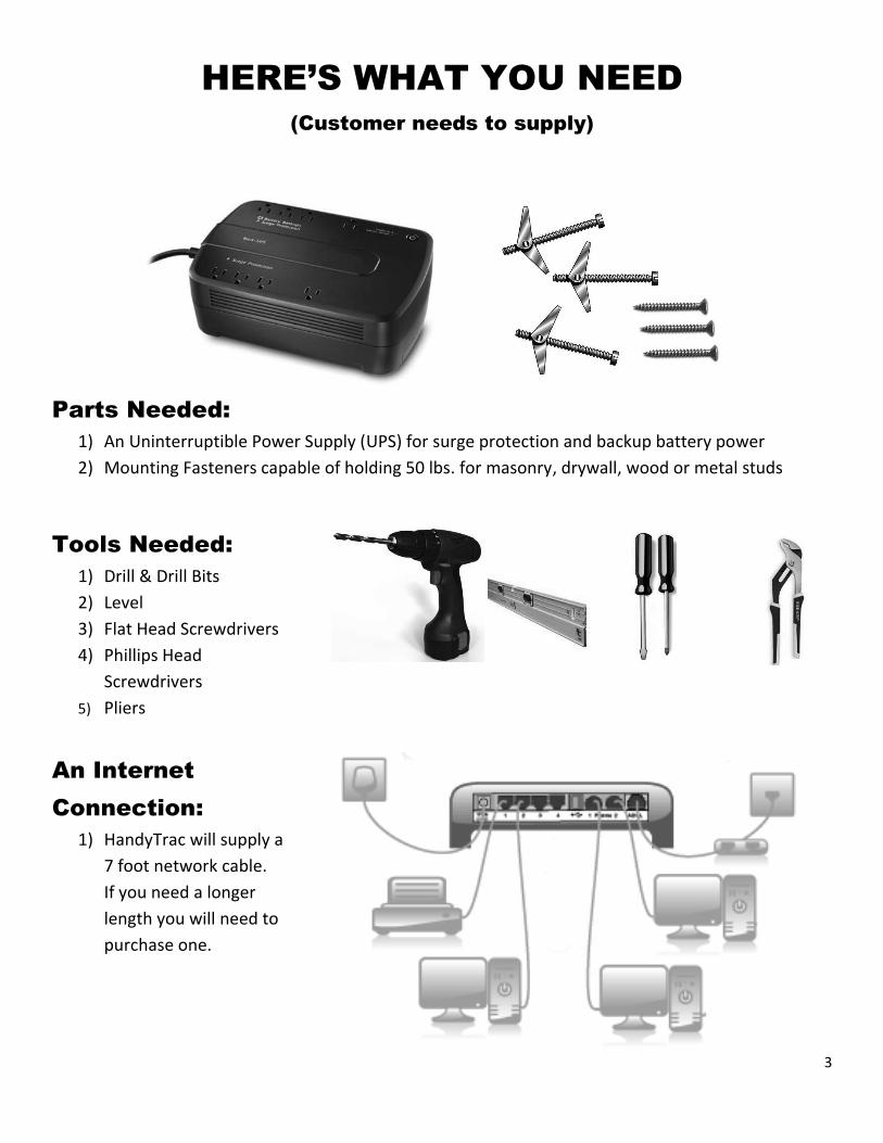
1) An Uninterruptible Power Supply (UPS) for surge protection and backup battery power
2) Mounting Fasteners capable of holding 50 lbs. for masonry, drywall, wood or metal studs
Tools Needed:
1) Drill & Drill Bits
2) Level
3) Flat Head Screwdrivers
4) Phillips Head
Screwdrivers
5) Pliers
An Internet
Connection:
1) HandyTrac will supply a
7 foot network cable.
If you need a longer
length you will need to
purchase one.
4
Here's a summary of the steps to install your System
1) Mount the Cabinet on the wall 2) Mount the Control Box and Datalog-Keypad on the wall 3) Insert Key Panels
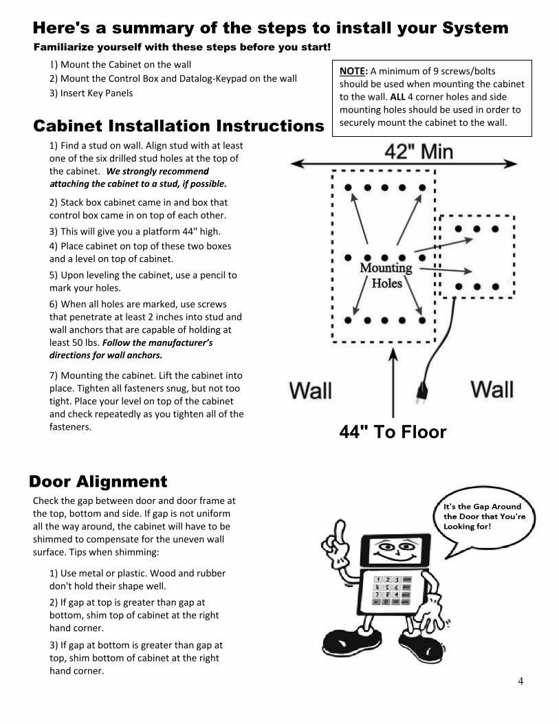
Cabinet Installation Instructions Find a stud on wall. Align stud with at least
one of the six drilled stud holes at the top ofthe cabinet. We strongly recommend�a
ttaching the cabinet to a stud, if possible.
Stack box cabinet came in and box thatcontrol box came in on top of each other.
This will give you a platform 4 " high.Place cabinet on top of these two boxes
and a level on top of cabinet.Upon leveling the cabinet, use a pencil to
mark your holes.When all holes are marked, use screws
that penetrate at least 2 inches into stud and wall anchors that are capable of holding atleast 50 lbs. Follow the manufacturer’s�directions for wall anchors.
Mounting the cabinet. Lift the cabinet into place. Tighten all fasteners snug, but not too tight. Place your level on top of the cabinet and check repeatedly as you tighten all of the fasteners.
Familiarize yourself with these steps before you start!
Door Alignment Check the gap between door and door frame at the top, bottom and side. If gap is not uniform all the way around, the cabinet will have to be shimmed to compensate for the uneven wall surface. Tips when shimming:
1) Use metal or plastic. Wood and rubberdon't hold their shape well. 2) If gap at top is greater than gap atbottom, shim top of cabinet at the righthand corner.
3) If gap at bottom is greater than gap attop, shim bottom of cabinet at the righthand corner.
NOTE: A minimum of 9 screws/bolts should be used when mounting the cabinet to the wall. ALL 4 corner holes and side mounting holes should be used in order to securely mount the cabinet to the wall.
5
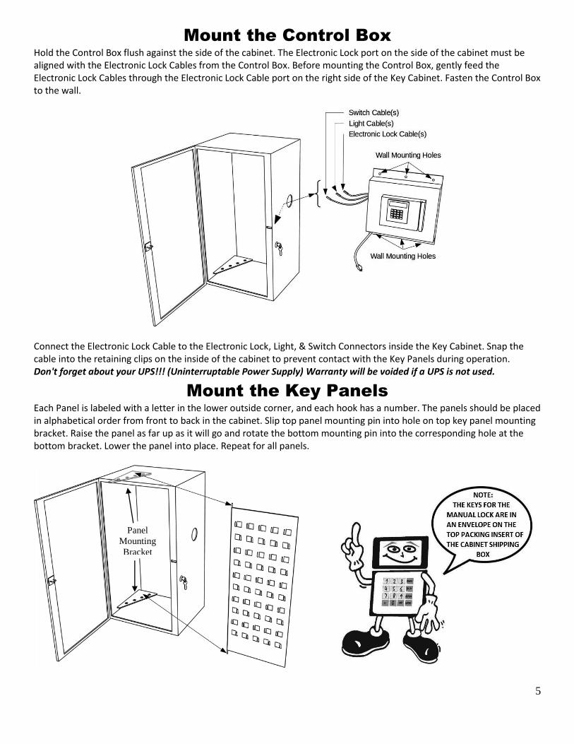
Mount the Control Box
Hold the Control Box flush against the side of the cabinet. The Electronic Lock port on the side of the cabinet must be aligned with the Electronic Lock Cables from the Control Box. Before mounting the Control Box, gently feed the Electronic Lock Cables through the Electronic Lock Cable port on the right side of the Key Cabinet. Fasten the Control Box to the wall.
Connect the Electronic Lock Cable to the Electronic Lock, Light, & Switch Connectors inside the Key Cabinet. Snap the cable into the retaining clips on the inside of the cabinet to prevent contact with the Key Panels during operation. Don't forget about your UPS!!! (Uninterruptable Power Supply) Warranty will be voided if a UPS is not used.
Mount the Key Panels
Each Panel is labeled with a letter in the lower outside corner, and each hook has a number. The panels should be placed in alphabetical order from front to back in the cabinet. Slip top panel mounting pin into hole on top key panel mounting bracket. Raise the panel as far up as it will go and rotate the bottom mounting pin into the corresponding hole at the bottom bracket. Lower the panel into place. Repeat for all panels.
Panel
Mounting
Bracket
6
1 2
3 4
5
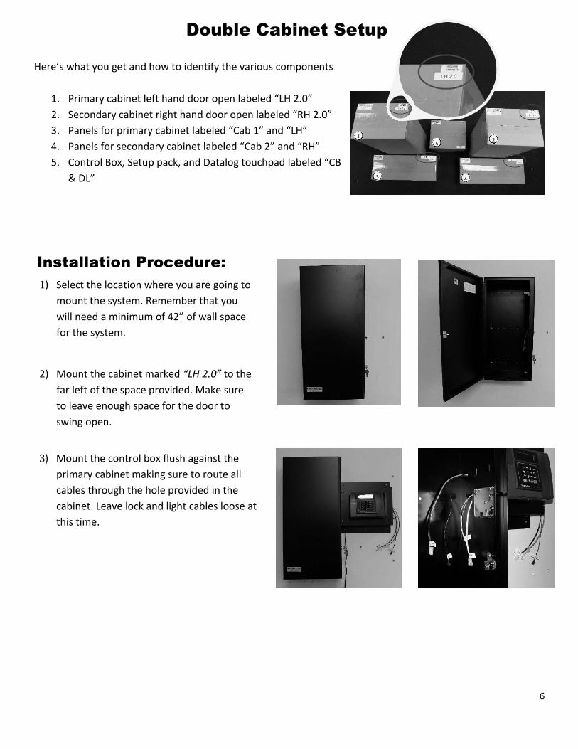
Double Cabinet Setup
Here’s what you get and how to identify the various components
1. Primary cabinet left hand door open labeled “LH 2.0”
2. Secondary cabinet right hand door open labeled “RH 2.0”
3. Panels for primary cabinet labeled “Cab 1” and “LH”
4. Panels for secondary cabinet labeled “Cab 2” and “RH”
5. Control Box, Setup pack, and Datalog touchpad labeled “CB
& DL”
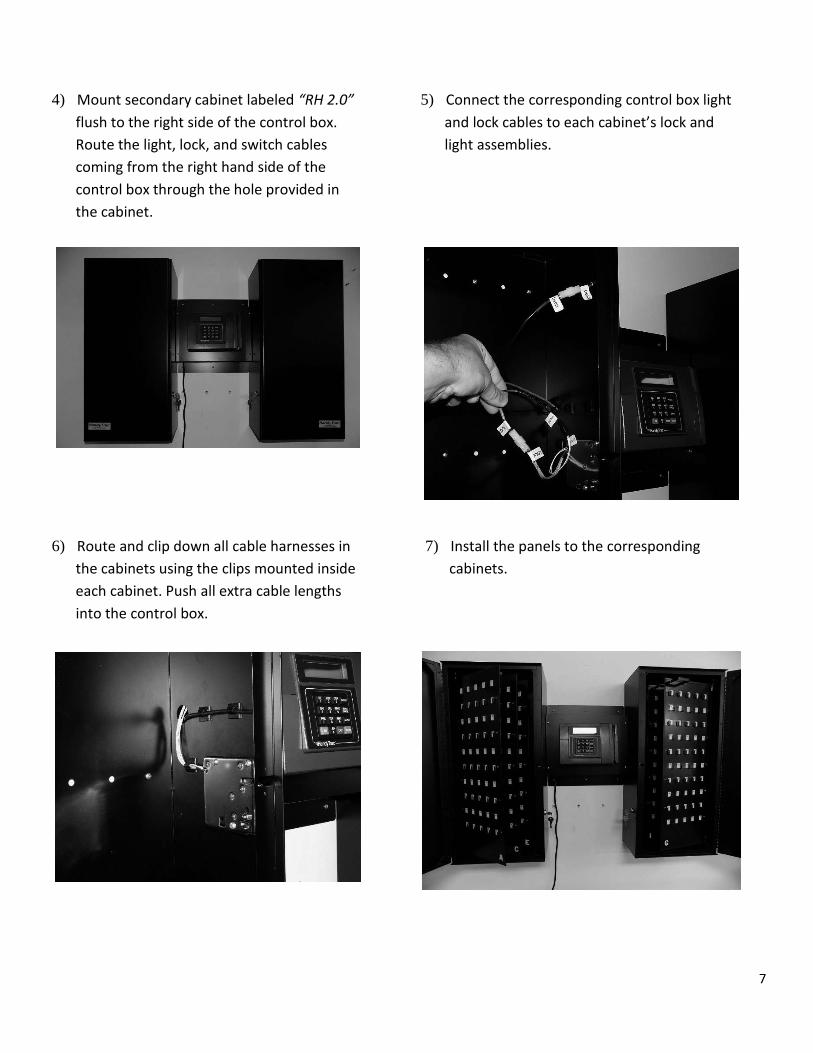
Installation Procedure:
1) Select the location where you are going to
mount the system. Remember that you
will need a minimum of 42” of wall space
for the system.
2) Mount the cabinet marked “LH 2.0” to the
far left of the space provided. Make sure
to leave enough space for the door to
swing open.
3) Mount the control box flush against the
primary cabinet making sure to route all
cables through the hole provided in the
cabinet. Leave lock and light cables loose at
this time.
7
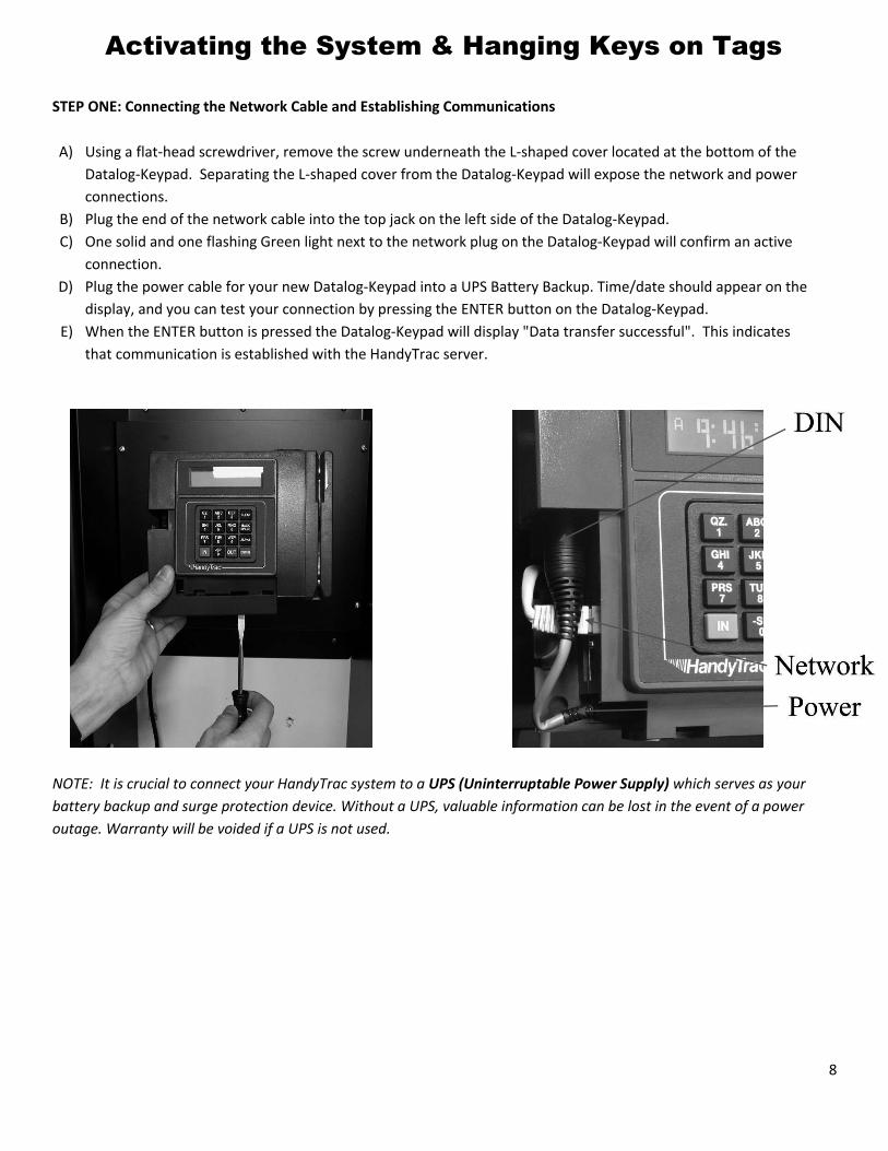
4) Mount secondary cabinet labeled “RH 2.0”
flush to the right side of the control box.
Route the light, lock, and switch cables
coming from the right hand side of the
control box through the hole provided in
the cabinet.
5) Connect the corresponding control box light
and lock cables to each cabinet’s lock and
light assemblies.
6) Route and clip down all cable harnesses in
the cabinets using the clips mounted inside
each cabinet. Push all extra cable lengths
into the control box.
7) Install the panels to the corresponding
cabinets.
8
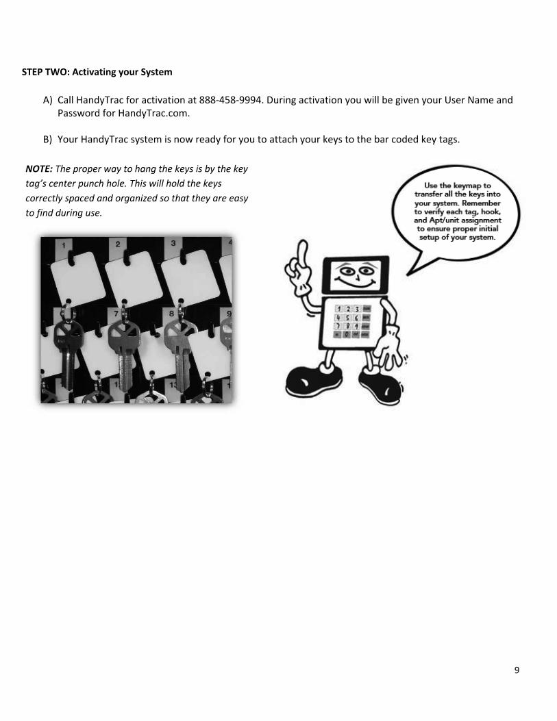
Activating the System & Hanging Keys on Tags
STEP ONE: Connecting the Network Cable and Establishing Communications
A) Using a flat-head screwdriver, remove the screw underneath the L-shaped cover located at the bottom of the Datalog-Keypad. Separating the L-shaped cover from the Datalog-Keypad will expose the network and power connections.
B) Plug the end of the network cable into the top jack on the left side of the Datalog-Keypad.
C) One solid and one flashing Green light next to the network plug on the Datalog-Keypad will confirm an active connection.
D) Plug the power cable for your new Datalog-Keypad into a UPS Battery Backup. Time/date should appear on the display, and you can test your connection by pressing the ENTER button on the Datalog-Keypad.
E) When the ENTER button is pressed the Datalog-Keypad will display "Data transfer successful". This indicates
that communication is established with the HandyTrac server.
NOTE: It is crucial to connect your HandyTrac system to a UPS (Uninterruptable Power Supply) which serves as your
battery backup and surge protection device. Without a UPS, valuable information can be lost in the event of a power
outage. Warranty will be voided if a UPS is not used.
9
STEP TWO: Activating your System
NOTE: The proper way to hang the keys is by the key
tag’s center punch hole. This will hold the keys
correctly spaced and organized so that they are easy
to find during use.
A) Call HandyTrac for activation at 888-458-9994. During activation you will be given your User Name and Password for HandyTrac.com.
B) Your HandyTrac system is now ready for you to attach your keys to the bar coded key tags.
10
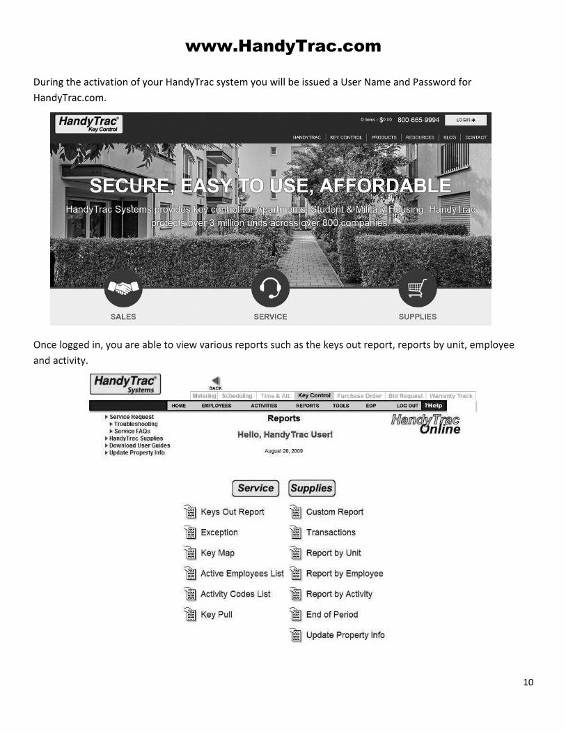
www.HandyTrac.com
During the activation of your HandyTrac system you will be issued a User Name and Password for
HandyTrac.com.
Once logged in, you are able to view various reports such as the keys out report, reports by unit, employee
and activity.
11
The Key Map shows the current location of the keyset. This
information needs to be kept confidential. Remember to
Keep it in a SAFE or other SECURE PLACE.
To Add an Employee
A) Click on the "EMPLOYEES" link located on the gray
task bar (pictured on previous page)
B) Enter the employee’s "First Name" & "Last Name"
in respected fields
C) Enter the "Badge Number" (the “15” barcode
number)
D) Fill in "PIN Number" (you may choose any 4-digit
PIN number you like)
E) Choose an "Access Level" for this employee
Employee - Employees who are just going to pull
and put keys back in
Master - Full administrative rights to the HandyTrac
system
F) Place a checkmark in the "Active" box to activate
this employee
G) Click on "Add/Update Employee"
H) Press the blue enter button on the Datalog-Keypad
to run the EOP update.
To Edit an Employee
A) Click on "EMPLOYEES" located on the gray task bar
B) Click on the drop down arrow in Active Employees
field
C) Highlight then click on the employee you wish to
Edit
D) Enter edits to employee information
E) Click on "Add/Update Employee"
F) Run EOP
To Deactivate an Employee
(Employees cannot be deleted, only deactivated once
added)
A) Follow directions to Edit an Employee
B) Remove checkmark in the active box
C) Click “Add/Update Employee” button and run the
EOP.
NOTE: It is critical that all employees
using the Handytrac System have their
own Badge and PIN number associated
with it. If badges or PIN numbers are
shared, the audit trail will not be valid.
12
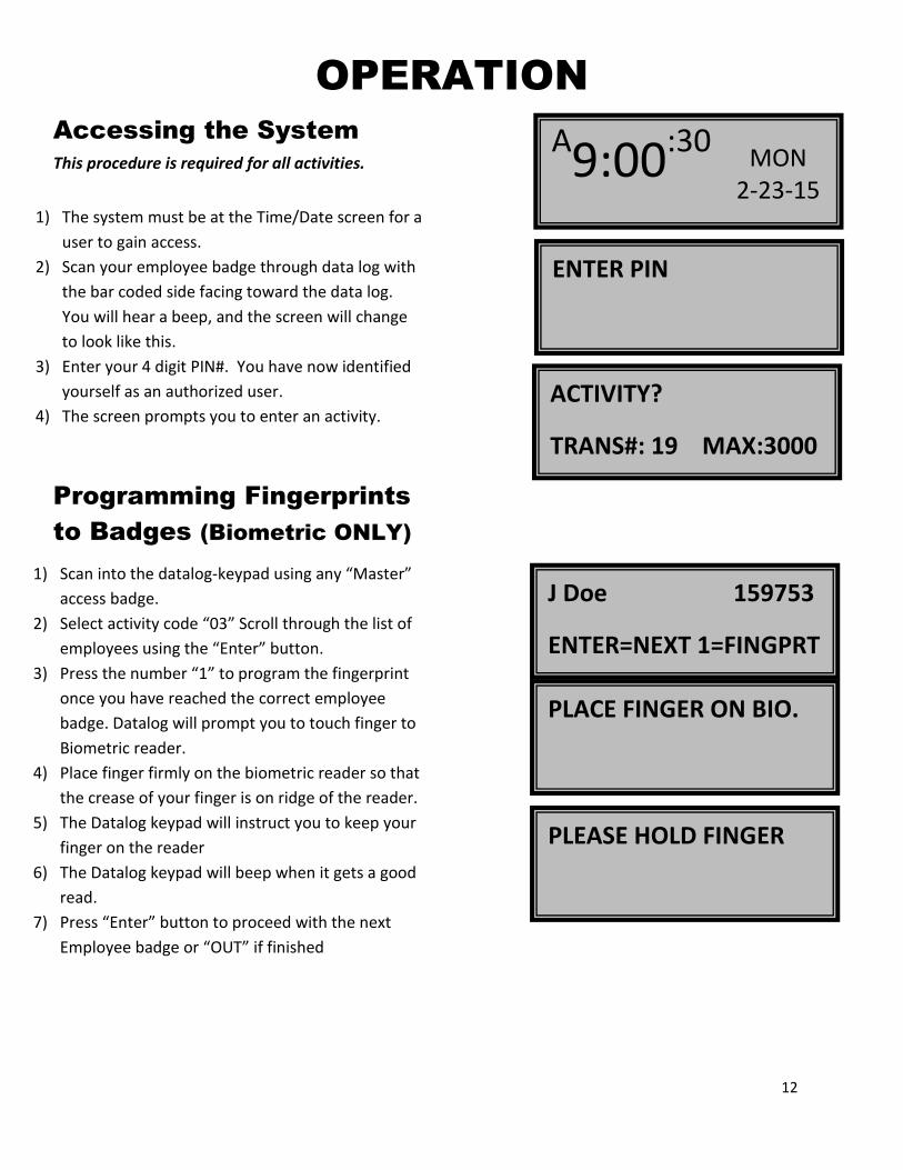
OPERATION
Accessing the System
This procedure is required for all activities.
1) The system must be at the Time/Date screen for a
user to gain access.
2) Scan your employee badge through data log with
the bar coded side facing toward the data log.
You will hear a beep, and the screen will change
to look like this.
3) Enter your 4 digit PIN#. You have now identified
yourself as an authorized user.
4) The screen prompts you to enter an activity.
Programming Fingerprints
to Badges (Biometric ONLY)
1) Scan into the datalog-keypad using any “Master”
access badge.
2) Select activity code “03” Scroll through the list of
employees using the “Enter” button.
3) Press the number “1” to program the fingerprint
once you have reached the correct employee
badge. Datalog will prompt you to touch finger to
Biometric reader.
4) Place finger firmly on the biometric reader so that
the crease of your finger is on ridge of the reader.
5) The Datalog keypad will instruct you to keep your
finger on the reader
6) The Datalog keypad will beep when it gets a good
read.
7) Press “Enter” button to proceed with the next
Employee badge or “OUT” if finished
A9:00:30 MON 2-23-15
ENTER PIN
ACTIVITY?
TRANS#: 19 MAX:3000
J Doe 159753
ENTER=NEXT 1=FINGPRT
PLACE FINGER ON BIO.
PLEASE HOLD FINGER
13
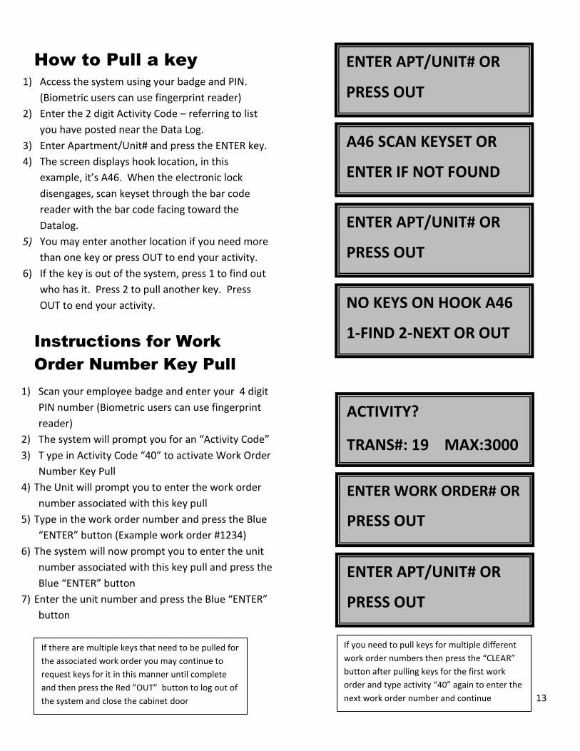
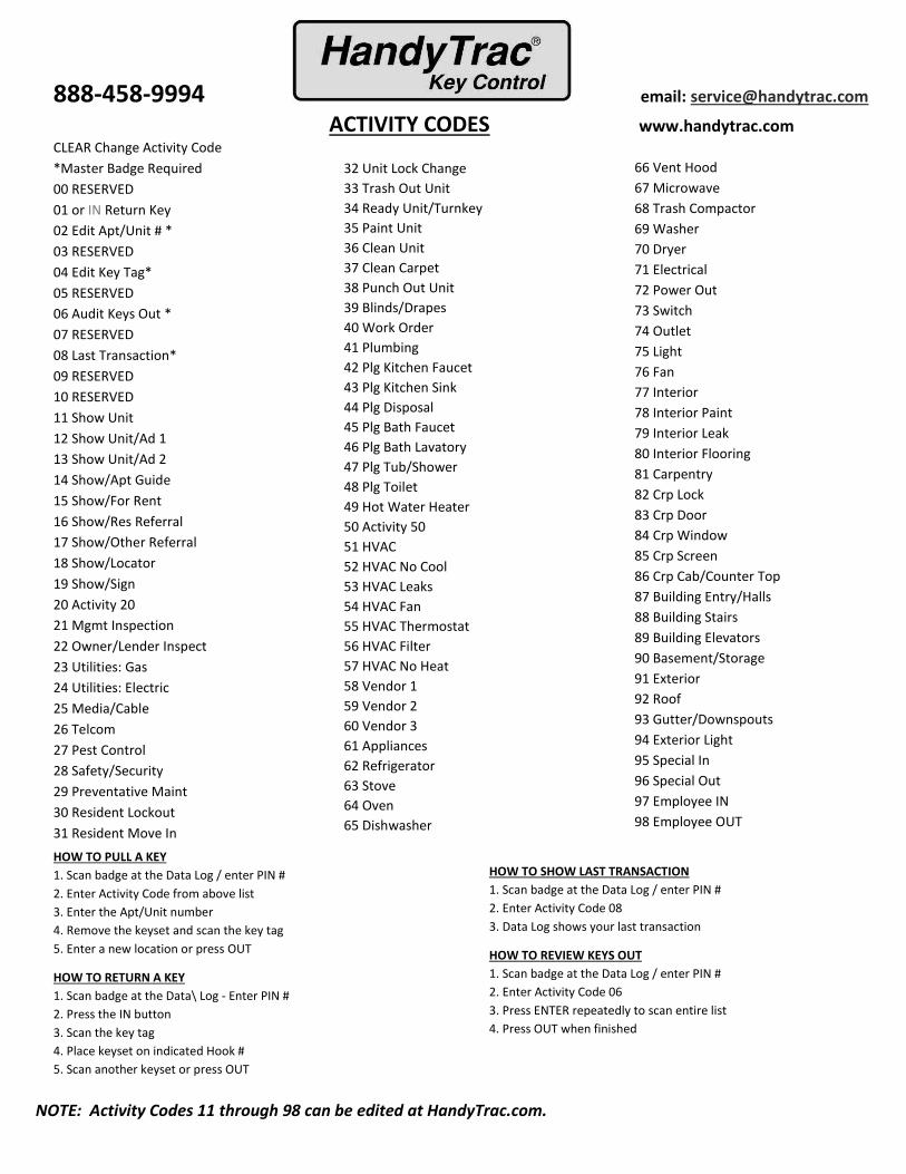
How to Pull a key
1) Access the system using your badge and PIN.
(Biometric users can use fingerprint reader)
2) Enter the 2 digit Activity Code – referring to list
you have posted near the Data Log.
3) Enter Apartment/Unit# and press the ENTER key.
4) The screen displays hook location, in this
example, it’s A46. When the electronic lock
disengages, scan keyset through the bar code
reader with the bar code facing toward the
Datalog.
5) You may enter another location if you need more
than one key or press OUT to end your activity.
6) If the key is out of the system, press 1 to find out
who has it. Press 2 to pull another key. Press
OUT to end your activity.
Instructions for Work
Order Number Key Pull
1) Scan your employee badge and enter your 4 digit
PIN number (Biometric users can use fingerprint
reader)
2) The system will prompt you for an “Activity Code”
3) T ype in Activity Code “40” to activate Work Order
Number Key Pull
4) The Unit will prompt you to enter the work order
number associated with this key pull
5) Type in the work order number and press the Blue
“ENTER” button (Example work order #1234)
6) The system will now prompt you to enter the unit
number associated with this key pull and press the
Blue “ENTER” button
7) Enter the unit number and press the Blue “ENTER”
button
ENTER APT/UNIT# OR
PRESS OUT
A46 SCAN KEYSET OR
ENTER IF NOT FOUND
ENTER APT/UNIT# OR
PRESS OUT
NO KEYS ON HOOK A46
1-FIND 2-NEXT OR OUT
ACTIVITY?
TRANS#: 19 MAX:3000
ENTER WORK ORDER# OR
PRESS OUT
If there are multiple keys that need to be pulled for
the associated work order you may continue to
request keys for it in this manner until complete
and then press the Red ”OUT” button to log out of
the system and close the cabinet door
ENTER APT/UNIT# OR
PRESS OUT
If you need to pull keys for multiple different
work order numbers then press the “CLEAR”
button after pulling keys for the first work
order and type activity “40” again to enter the
next work order number and continue
14
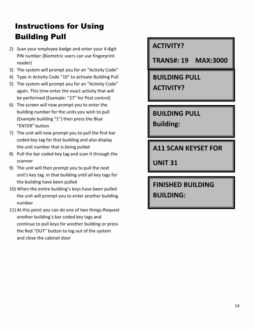
Instructions for Using
Building Pull
2) Scan your employee badge and enter your 4 digit
PIN number (Biometric users can use fingerprint
reader)
3) The system will prompt you for an “Activity Code”
4) Type in Activity Code “10” to activate Building Pull
5) The system will prompt you for an “Activity Code”
again. This time enter the exact activity that will
be performed (Example: “27” for Pest control)
6) The screen will now prompt you to enter the
building number for the units you wish to pull
(Example building “1”) then press the Blue
“ENTER” button
7) The unit will now prompt you to pull the first bar
coded key tag for that building and also display
the unit number that is being pulled
8) Pull the bar coded key tag and scan it through the
scanner
9) The unit will then prompt you to pull the next
unit’s key tag in that building until all key tags for
the building have been pulled
10) When the entire building’s keys have been pulled
the unit will prompt you to enter another building
number
11) At this point you can do one of two things:Request
another building’s bar coded key tags and
continue to pull keys for another building or press
the Red “OUT” button to log out of the system
and close the cabinet door
A11 SCAN KEYSET FOR
UNIT 31
FINISHED BUILDING
BUILDING:
ACTIVITY?
TRANS#: 19 MAX:3000
BUILDING PULL
ACTIVITY?
BUILDING PULL
Building:
15
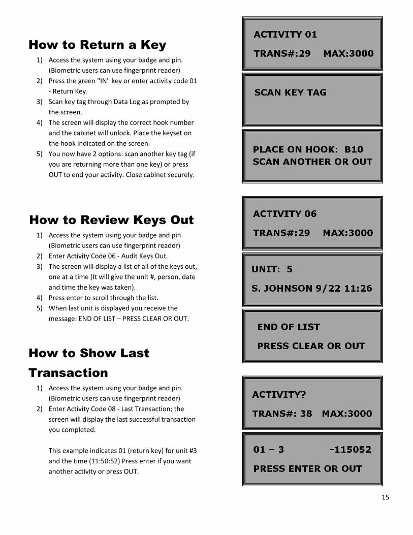
How to Return a Key
1) Access the system using your badge and pin.
(Biometric users can use fingerprint reader)
2) Press the green "IN" key or enter activity code 01
- Return Key.
3) Scan key tag through Data Log as prompted by
the screen.
4) The screen will display the correct hook number
and the cabinet will unlock. Place the keyset on
the hook indicated on the screen.
5) You now have 2 options: scan another key tag (if
you are returning more than one key) or press
OUT to end your activity. Close cabinet securely.
How to Review Keys Out
1) Access the system using your badge and pin.
(Biometric users can use fingerprint reader)
2) Enter Activity Code 06 - Audit Keys Out.
3) The screen will display a list of all of the keys out,
one at a time (It will give the unit #, person, date
and time the key was taken).
4) Press enter to scroll through the list.
5) When last unit is displayed you receive the
message: END OF LIST – PRESS CLEAR OR OUT.
How to Show Last
Transaction
1) Access the system using your badge and pin.
(Biometric users can use fingerprint reader)
2) Enter Activity Code 08 - Last Transaction; the
screen will display the last successful transaction
you completed.
This example indicates 01 (return key) for unit #3
and the time (11:50:52) Press enter if you want
another activity or press OUT.
16
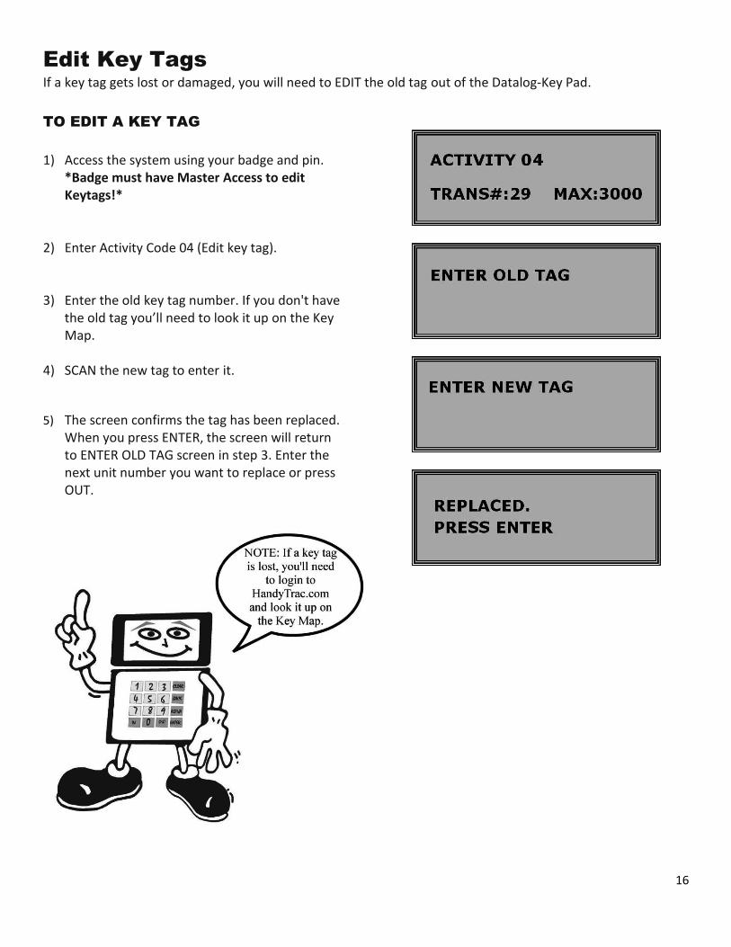
Edit Key Tags
If a key tag gets lost or damaged, you will need to EDIT the old tag out of the Datalog-Key Pad.
TO EDIT A KEY TAG
1) Access the system using your badge and pin. *Badge must have Master Access to edit
Keytags!* 2) Enter Activity Code 04 (Edit key tag).
3) Enter the old key tag number. If you don't have the old tag you’ll need to look it up on the Key Map.
4) SCAN the new tag to enter it.
5) The screen confirms the tag has been replaced. When you press ENTER, the screen will return to ENTER OLD TAG screen in step 3. Enter the next unit number you want to replace or press OUT.
17
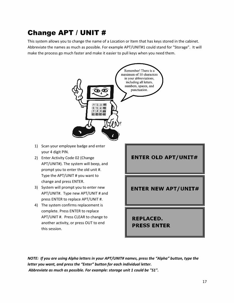
Change APT / UNIT #
This system allows you to change the name of a Location or Item that has keys stored in the cabinet.
Abbreviate the names as much as possible. For example APT/UNIT#1 could stand for "Storage". It will
make the process go much faster and make it easier to pull keys when you need them.
1) Scan your employee badge and enter
your 4 digit PIN.
2) Enter Activity Code 02 (Change
APT/UNIT#). The system will beep, and
prompt you to enter the old unit #.
Type the APT/UNIT # you want to
change and press ENTER.
3) System will prompt you to enter new
APT/UNIT#. Type new APT/UNIT # and
press ENTER to replace APT/UNIT #.
4) The system confirms replacement is
complete. Press ENTER to replace
APT/UNIT #. Press CLEAR to change to
another activity, or press OUT to end
this session.
NOTE: If you are using Alpha letters in your APT/UNIT# names, press the “Alpha” button, type the
letter you want, and press the “Enter” button for each individual letter.
Abbreviate as much as possible. For example: storage unit 1 could be "S1".