Page 1
Irrigated Acreage Determination Proceduresfor Wastewater Application Equipment
HARD HOSETRAVELER
IRRIGATION SYSTEM
North Carolina CooperativeExtension Service
North Carolina State University
Page 2
Irrigation continues to be the most practical and cost effective method of applying
wastewater to fields so that the nutrients contained in the wastewater can be used by
growing crops. However, irrigation systems have inherent application limitations that
make field calibration, irrigation scheduling, and determination of irrigated acreage
critical for proper use of the nutrients contained in the applied wastewater.
Irrigation systems are normally designed to satisfy equipment specifications
provided in manufacturers’ charts. Information presented in manufacturers’ charts are
based on average operating conditions for relatively new equipment. Discharge rates
and precipitation rates change over time as equipment ages and components wear.
Poor designs and/or improper operation can also cause poor performance. As a result,
equipment should be field calibrated regularly to ensure that application rates and
uniformity are consistent with values used during the system design and given in
manufacturers’ specifications. Field calibration is a simple procedure that involves
collecting and measuring the material being applied at several locations in the
application area. Step-by-step guidelines for field calibration of hard hose traveler
irrigation systems are given in Extension publication AG-553-2, Field Calibration
Procedures for Animal Wastewater Application Equipment: Hard Hose and Cable Tow
Traveler Irrigation System.
Irrigation must be scheduled when fields are dry enough to retain all of the applied
liquid within the root zone. If soils are too wet during irrigation, some of the applied
wastewater may run off the field or leach below the root zone and become unavailable
to the crop. These unused nutrients could contaminate surface or ground water supplies.
Determining when and how much wastewater to apply for the prevailing conditions is
referred to as irrigation scheduling. Irrigation scheduling techniques and procedures
are outlined in Extension publication AG-452-4 Irrigation Scheduling to Improve Water- and
Energy-Use Efficiencies.
Sprinkler irrigation systems do not apply water uniformly throughout their entire
wetted radius. Application depths tend to be higher near the sprinkler and decrease
gradually within the first 60 to 70 percent of the wetted radius. Beyond this point, the
application depth declines quickly, dropping to zero at the outer edge. Irrigation
design guidelines take equipment limitations into account in establishing
recommended overlap ranges to optimize uniformity of coverage. Determining the
uniformly irrigated area for traveler systems can be difficult for travel lanes along the
perimeter of the field, for non-uniform travel lane spacings, or for excessive travel lane
spacings with improper overlap. This publication contains step-by-step guidelines for
determining irrigated acreage of hard hose traveler irrigation systems.
2
Irrigated Acreage Determination Proceduresfor Wastewater Application Equipment
HARD HOSETRAVELERIRRIGATION SYSTEM
Page 3
BackgroundTravel lane spacing and design guidelines have been
developed primarily for freshwater irrigation with the
primary goal of ensuring that those areas of the field
receiving the least amount of water receive enough to
sustain the crop and achieve yield goals. To achieve
minimum desired application depths within the
“lighter application zones,” travel lane spacings of 70
to 75 percent of the wetted sprinkler diameter have
been determined to be “optimum” to compensate for
the declining application along the perimeter. Closer
lane spacings are sometimes economically justified for
higher value crops; however, closer spacings may also
result in some overlap zones receiving more water than
necessary, and certainly more than the average. A good
irrigation design considers these factors and uses a
travel lane spacing that achieves a balance between the
relative proportion of “under” and “over” irrigated area
in order to achieve the most uniform application
possible.
The application uniformity can be quantified using
one of several uniformity indices. The uniformity
index recommended for wastewater application is the
Christiansen Uniformity Coefficient, Uc. Step-by-step
computational procedures are outlined in Extension
publication AG-553-2, referenced in the previous
section. An application uniformity index of 60 is the
minimum acceptable for wastewater application using
hard hose traveler systems. Irrigation systems should
be field calibrated regularly to ensure that application
uniformity is within the acceptable range. Field
calibration can also be used to determine the area
within a field receiving a uniformly acceptable
application.
Irrigated AcreageIn an effort to answer technical specialists’ questions
and to provide uniform interpretations of the state’s
animal waste management rules, the North Carolina
General Assembly formed an interagency committee in
1996. The SB 1217 Interagency Committee is
composed of two representatives of each of the five
agencies with responsibilities for the development
and/or enforcement of animal waste management
rules. The committee recently adopted guidelines and
procedures for determining the acreage that can be
counted toward the “irrigated area” in satisfying the
Certified Animal Waste Management Plan (CAWMP).
The committee considered many factors including
recommendations from irrigation engineers, certified
irrigation designers, and industry representatives before
arriving at these guidelines. The irrigated acreage
determined by these procedures is intended to
“reasonably and practically” account for physical
limitations of the application equipment. The
“irrigated acreage” computed by the procedures
presented below must equal or exceed the acreage
requirement specified in the CAWMP for proper
nutrient use.
The irrigated area determination includes two
broad categories: existing irrigation systems
–those systems installed before the guidelines were
finalized–and new systems or expanded systems
installed after the SB 1217 committee released the third
revision of the Sixth Guidance Document. Future
updates and revisions may occur, so you should refer
to the most recent Guidance Document for the latest
interpretation and effective dates.
For the purpose of computing the irrigated acreage
available to satisfy the CAWMP, the SB 1217
Interagency Committee adopted the term “CAWMP
wettable acre” to be applied to existing systems.
This term applies to existing systems that satisfy
minimum specifications as outlined below. The
irrigated acreage for new or expanded irrigation
systems should continue to be based on standard
irrigation design guidelines, which are based on the
effective design area. The term expanded irrigation
system applies to new irrigation components that wet
an area of a field that was not wetted before adoption
of the new guidelines. These terms are defined below.
3
HARD HOSE TRAVELERIRRIGATION SYSTEM
Page 4
Existing irrigation systems—For hard hose traveler
systems designed and installed in accordance with
minimum overlap guidelines (lane spacing between 60
and 90 percent of verified wetted diameter) and laid
out with multiple overlapping lanes, the CAWMP
wettable acre allowance is the entire “net wetted area”
in the field. The net wetted area is the part of
the field that gets “wetted” during two or
more parallel pulls of the gun when operated
during normal conditions, i.e., wind speed
under 5 mph.
The “wetted area” for a single pull without overlap
is the area inscribed within the wetted diameter and
length of pull as shown in Figure 1. For multiple pulls
such as shown in Figure 2, the wetted area is also the
entire shaded area; but, in this publication, this area is
referred to as “net wetted area.” Due to the overlap,
some of the same areas are wetted during adjacent
pulls. These overlap areas cannot be counted twice,
hence the term “net” is used.
For a hard hose traveler system, there are two
travel lane designations within the field that affect
determination of irrigated acreage.
• Interior travel lane
• Exterior travel lane
An interior travel lane is any lane that receives
overlap on both sides of the pull as shown in Figure 3.
The center lane is an interior lane. Travel lanes along
the perimeter of the field receive overlap on just one
side and are referred to as exterior travel lanes.
Figure 2. Shaded area shows net wetted area for a field irrigated with a hard hose travelerwith mutiple lanes. (The net wetted area for thethree parallel pulls is less than three times thearea of a single pull, Figure 1, due to overlap.)
Figure 3. CAWMP wettable acre allowance forexisting systems based on net wetted area forexterior (darker shaded) and interior travel lanes.
Irrigated Acreage Determination Proceduresfor Wastewater Application Equipment
4
Exterior lane
Exterior lane
Interior lane
1.0r
Figure 1. Area “wetted” during a single pull of ahard hose traveler.
Page 5
Note that the net wetted area allowance for an exterior
lane is larger than the net wetted area allowance for an
interior lane. This is due to overlap.
In single travel lanes with no overlap, the outer
wetted edge cannot be counted under CAWMP
wettable acre rules. In this case, the net wetted area is
computed based on 90 percent of the verified wetted
diameter as shown in Figure 4. For any system in
which the lane spacing exceeds 90 percent of the
verified wetted diameter, each lane should be treated as
a “single lane” case.
The system layout, including determination of lane
spacing and the number of interior and exterior lanes,
must be determined in order to compute the CAWMP
irrigated acreage of an existing system. The CAWMP
wettable acre rules distinguish between existing
systems with two or more overlapping travel lanes
and existing systems with only one travel lane without
overlap. For multiple lanes, the CAWMP wettable
acre allowance is “all” of the area wetted, whereas
only 90 percent of the area wetted can be counted for
single pulls.
New or Expanded Irrigation Systems—New
or expanded irrigation systems must follow recom-
mended design standards, which base the allowable
irrigated area on the effectively irrigated area,
referred to in this publication as the “design
area.”
The effective irrigated area is the wetted
area that receives at least 50 percent of the
target application amount. From field calibration
measurements, this has been determined to be the area
that falls within 78 percent of the wetted radius as
shown in Figure 5. Note that application depths
remain within 90 percent of the target amount out to
60 percent of the wetted radius. Between 60 and 70
percent of the wetted radius, application amounts still
remain within 80 percent of the target application
amount. But beyond 70 percent of the wetted radius,
application amounts drop off quickly, declining to 50
percent by 78 percent of the wetted radius. At 90
percent of the wetted radius, the application depth
drops below 20 percent. Traditional design spacing
guidelines established by the North Carolina
Cooperative Extension Service for traveling gun
systems have been for 60 to 75 percent of
manufacturers’ published wetted diameter. These
recommendations are strongly collaborated by the data
shown in Figure 5. A multi-travel lane system (such as
shown in Figure 2 or 3), operated under light wind
with exactly a 78 percent lane spacing, would result in
a nearly perfect application uniformity. Even if the
lane spacing were stretched out to 85 percent of the
wetted diameter, the minimum application amount
would be 50 percent of the target amount along the
overlapped zone, which would still result in acceptable
uniformity. It should be noted that the results shown
in Figure 5 are based on field-verified wetted
5
0.9r
HARD HOSE TRAVELERIRRIGATION SYSTEM
Figure 4. Shaded area shows allowable “irrigatedarea” for existing single pull hard hose traveler.
Figure 5. Normalized application depth versusdistance from a gun or sprinkler.
Page 6
Irrigated Acreage Determination Proceduresfor Wastewater Application Equipment
diameters. Recent measurements on more than
50 systems determined that field-measured wetted
diameters averaged 10 percent less than values
published in manufacturers’ literature. A spacing
based on 85 percent of field-verified wetted diameter
is roughly the same as a spacing based on 77 percent
of manufacturers’ values. Thus, a design spacing
recommendation of 60 to 75 percent of manufacturers’
values (N.C. Cooperative Extension Service guideline)
is a conservative recommendation to ensure that
enough wastewater is applied in the lighter application
zones. The Extension recommendations should
continue to be applied to new or expanded systems.
Spacings greater than 85 percent of the verified wetted
diameter or 75 percent of the wetted diameter
published in manufacturers’ literature are considered
excessive and result in unacceptable uniformity.
For existing irrigation systems involving a single
pull or excessive lane spacing, the CAWMP wettable
acre should be based on no more than 90 percent of
the verified wetted gun diameter as shown in Figure 4.
When using new systems with single pulls or excessive
lane spacing, base the CAWMP wettable acre on no
more than 75 percent of the manufacturer’s published
wetted gun diameter as shown in Figure 6.
Field MeasurementsTo accurately calculate the irrigated area, determine
the wetted diameter or radius of the gun. There are two
methods for determining the wetted diameter, and
both require operating the system:
• Directly measure the wetted diameter (footprint),
or
• Measure gun pressure, then read the wetted
diameter from manufacturers’ charts for the
observed pressure.
The recommended procedure is to determine the
wetted diameter (also referred to as wetted footprint)
rather than rely on pressure and manufacturers’ tables.
Values given in manufacturers’ charts tend to be about
10 percent higher than values measured in field
calibrations. Regardless of the method used, collect
field data and record it on the Field Data Worksheet
provided at the end of this publication.
Footprint measurement—Footprint measurement
involves observing, marking, and measuring the
farthest distance from the gun that gets wetted. Field
data should be collected on the lane farthest from the
pump. Measuring two or more different lanes improves
the reliability of the field procedures. Measurements
should be made during very light wind (less than 5
mph). The wetted distance from the gun should be
determined on both sides of the lane along the
perimeter as indicated in Figure 7. The system should
be operated long enough for all air to be purged from
the system before starting to make measurements.
With the system operating at normal pressure:
1. Standing just outside the wetted perimeter,
observe and flag the farthest point getting
wetted for each of three consecutive passes of
the gun.
2. Select one flag to mark the average distance of
the three observations. Remove the other two
flags.
3. Move to the other side of the lane (180 degrees
around the wetted perimeter) and repeat steps
1 and 2. The wetted perimeter should be
flagged on two sides of the gun as shown in
Figure 7.
6
0.78
r
Figure 6. Shaded area shows allowable irrigatedarea based on “effective design area” for new orexpanded systems.
Page 7
4. Measure and record the distances from the
gun (travel lane) to each flag.
5. Compare the two measurements and if the
values are within 5 percent, compute the
average of the two; this will be the wetted
radius. If the difference between the
measurements is more than 5 percent, repeat
steps 1 through 4 at another location along
the lane or along a different lane.
6. If the difference between the second set of
measurements is also greater than 5 percent,
the wind speed may be too high, resulting in
excessive drift; or, the gun may be functioning
improperly. Once you have eliminated or
corrected the cause of the variability, repeat,
beginning with step 1. If you cannot correct
the problem, contact an irrigation technical
specialist.
Pressure measurement—The wetted diameter canalso be estimated from pressure measurements at thegun. Pump pressure is NOT an acceptablesubstitute.
Collect field data when the system is operated on
the lane farthest from the pump. You should operate
the system long enough for all air to be purged from
the system before measuring the pressure.
Gun type sprinklers have a port for installing a
pressure gauge, shown in Figure 8. A glycerin-filled
gauge is recommended. Permanently installed gauges
are likely to foul, so it is also recommended that you
install a shut-off valve between the gauge and gun.
The valve can be opened long enough to read the
pressure, then closed to extend the life of the gauge.
It is also necessary to determine the exact size of
the nozzle opening. Most manufacturers stamp the
nozzle size on the end of the nozzle. If the nozzle
opening cannot be read, a precise measurement using
calipers is required.
7
Flag marking wetted radius
+
0.78
r
Middle rectangular area
Start-end areaStop-end area
HARD HOSE TRAVELERIRRIGATION SYSTEM
Figure 7. Field measurements to determine“wetted diameter” of a hard hose traveler.
Figure 8. Pressure gauge installed on a travelinggun.
Figure 9. Area components of traveler pull requiredto compute total irrigated area for a lane.
Page 8
Once you
measure the
operating pressure
and nozzle
opening, estimate
the wetted
diameter from the
manufacturer’s
literature. When
using tables in this
publication to
determine irrigated
acreage, reduce the
value taken from manufacturers’ charts by
10 percent.
The gun pressure can sometimes be estimated based
on direct pressure measurements at the reel if pressure
losses in the flexible hose and drive mechanism are
properly accounted for. This procedure should be used
only when footprint measurement or pressure
measurement at the gun cannot be completed.
Determining Irrigated Acreage Once you collect the necessary field data and
determine the wetted radius or diameter, compute the
CAWMP wettable acres. Computations are not
difficult; but they can become cumbersome for non-
uniform lane spacings, lane spacings with improper
overlap, and pulls along the perimeter of the field.
To simplify the determination of irrigated acreage,
computations have been tabulated for the end areas of
the pull for typical lane spacings and patterns. Use of
these tables requires precise determination of wetted
diameter, system layout, and the number of interior
and exterior travel lanes as defined earlier. Step-by-step
computational procedures are outlined in the
Computational Worksheet provided at the end of this
publication. A flowchart for using the tables is shown
in Figure 14.
Existing systems with multiple lanes:
Determining the irrigated area for each pull
involves doing calculations for three area components
of the pull—“start-end” area, “middle” area, and “stop-
end” area. These areas are shown in Figure 9.
Start-end area—Start-end areas have been computed
for lane spacings between 60 to 90 percent of wetted
diameter and are shown in column (B) in Tables
EE60 to EE90 for Existing Exterior (EE) lanes and
Tables EI60 to EI90 for Existing Interior (EI) lanes.
Middle area—The middle area must be computed
based on the net wetted width and the length of pull.
There are endless combinations of “length of pull,” so
it is not practical to tabulate these values. Instead, you
should compute this area by multiplying the length
and width of the rectangular area shown in Figure 9.
Stop-end area—The stop-end area is influenced by
the wetted diameter of the gun and the angle of gun
rotation referred to as “gun arc angle,” shown in Figure
10. Gun arc angles commonly range from 180 to 330
degrees. Typical arc angles are shown in Figure 11.
Stop-end areas based on several common arc angles are
tabulated in columns C through G of Tables EE60 to
EE90 for existing exterior lanes and Tables EI60 to
EI90 for existing interior lanes.
Existing system with single lane or lane
spacing greater than 90 percent.
Irrigated acreage determination for fields with a
single pull or where the lane spacing exceeds 90
percent of the wetted diameter involves determination
of the three area components just as in the previous
section. However, only 90 percent of the wetted area is
used in computing the irrigated area. Use Table E90+
for existing systems with single pulls or when lane
spacings exceed 90 percent of wetted diameter.
New or expanded systems: Determination of
irrigated area for new or expanded systems involves
determination of the three area components—start-
end, middle, and stop-end areas. But irrigated acreage
Figure 10. Recommendedarc angle of gun for usewith hard hose traveler.
Irrigated Acreage Determination Proceduresfor Wastewater Application Equipment
8
α = 330
α
Page 9
for new or expanded systems is based on the effective
design area, which is computed based on 78 percent of
the wetted diameter. These values are given in Tables
NE60 to NE75 for New Exterior (NE) lanes and Tables
NI60 to NI75 for New Interior (NI) lanes. Values for
new single lane systems are shown in Table N75+.
You should follow these general guidelines in using
the tabulated values presented in this publication.
Make decisions on a field-by-field basis as referenced
in the CAWMP.
1. Determine the number of interior and
exterior lanes for each field.
2. Determine whether the system in each field
satisfies the existing or new designation.
3. Obtain the lane spacing from the Field Data
Worksheet (i.e., field-measured lane spacing).
4. Determine whether the system satisfies the
multiple lane or single lane definition. If
the lane spacing exceeds 90 percent of the
verified wetted diameter, treat the system as an
existing system with single pulls and read the
irrigated acreage from Table E90+.
5. Read or compute the irrigated area per lane for
the given wetted diameter from the
appropriate column based on gun position,
lane spacing, and lane position.
Start-end area
Read the irrigated area for the start-end of the
pull from column B of the appropriate table
based on lane spacing and position (exterior or
interior).
Rectangular area (middle component)
Compute the area of the rectangular
component using the formula:
Exterior lane
Middle area = length of pull x (wetted
diameter / 2 + lane spacing / 2)/43,560
Interior lane
Middle area = (length of pull x lane
spacing)/43,560
Stop-end area
Read the irrigated area for the stop-end of the
pull from the appropriate table based on lane
spacing and position (exterior or interior) and
gun arc angle, columns C through G.
If the lane spacing falls between the tabulated
values, interpolate or round down and use
Figure 11. Typical gun arc angles used for travelinggun systems.
9
HARD HOSE TRAVELERIRRIGATION SYSTEM
α = 180 α = 225
α = 270 α = 315
Page 10
the table for the next lowest value shown. For
example, if the computed spacing is between
70 and 74 percent, use the 70 percent table.
6. Add the area components for each pull, then
add all of the pulls. This is the total irrigated
acreage for the field.
Determining Irrigated Acreage EXAMPLES Case I: Multiple lanes Figure 12 shows a typical lane spacing and pattern for
a hard hose traveler system. This existing system has
five pulls laid out in the field. The travel distance of
the gun is 820 feet and the gun angle is 330 degrees.
1. Determine the number of interior and exterior
lanes for each field. In Figure 12, lanes 1 and 5
are exterior lanes; lanes 2 , 3, and 4 are interior
lanes.
Number of exterior lanes = 2
Number of interior lanes = 3
2. Determine whether the system in each field
satisfies the existing or new designation.
System satisfies existing designation.
3. Using the Field Data Worksheet, determine the
lane spacing.
The lane spacing (item 6) is 220 feet. The
wetted diameter (item 7) is 290 feet.
Lane spacing as a percentage of wetted diameter
is: 220 feet / 290 feet = 75.9 percent
4. Determine whether the system satisfies the
multiple lateral or single lateral definition. System satisfies the multiple lateral system definition with lateral spacing
equal to 75.9 percent of wetted diameter.
5. Read the irrigated area per lane for the
given wetted diameter from the appropriate
column based on gun position, lane spacing,
and lane position. For a wetted diameter of 290
feet and lane spacing of 75 percent:
Exterior lane, Table EE75
Start-end area = 0.70 acresMiddle area = 820 feet x (290 feet /2 +
220 feet /2)/43,560 = 4.80 acres
Stop-end area (315 arc angle) = 0.51 acres Total for exterior = 0.70 + 4.80 + 0.51 =
Figure 12. Hard hose traveler irrigated area determination.
Irrigated Acreage Determination Proceduresfor Wastewater Application Equipment
10
Exterior lane
Interior Lane
Interior Lane
Exterior laneLane spacing/2 = 220/2
Diameter/2 = 290/2
Lane spacing = 220
Travel length = 820'
Interior lane
Interior lane
Interior lane
Lane 1
Lane 2
Lane 3
Lane 4
Lane 5
Page 11
6.01 acres
Interior lane, Table EI75
Start-end area = 0.65 acres
Middle area = (820 feet x 220 feet)
/43,560 = 4.14 acres
Stop-end area (315 arc angle) = 0.46 acres
Total for interior = 0.65 + 4.14 + 0.46 =
5.25 acres
6. Multiply the areas from step 5 by the number
of lanes in each category. Add these. The sum is
the total irrigated acreage for the field.
2 exterior lanes X 6.01 acres/lane =
12.02 acres
3 interior lanes X 5.25 acres/lane =
15.75 acres
Total irrigated area of field
12.02 ac + 15.75 ac = 27.77 acres
Case II: Single lane (also use this procedure forlane spacing greater than 90 percent of wetteddiameter). Figure 13 shows a typical field situation
that would result in a single lane. Data and irrigated
area must be reported on a field-by-field basis. These
fields are surrounded by drainage ditches spaced 330
feet apart. This existing system has one lane per field
and uses a model 150 gun. The travel distance of the
gun is 900 feet, and the gun angle is 270 degrees.
1. Determine the number of interior and
exterior lanes for each field. In Figure 13,
there is only one pull per field.
Number of lanes per field = 1
2. Determine whether the system in each field
satisfies the existing or new designation.
System satisfies existing designation.
3. Using the Field Data Worksheet, determine the
lane spacing.
Not applicable since there is only one lane per
field.
4. Determine whether the system satisfies the
multiple lane or single lane definition.
System satisfies single lane.
5. Read the irrigated area per lane for the given
wetted diameter from the appropriate column
based on gun position, lane spacing, and lane
position. For a wetted diameter of 290 feet and
single lane system:
11
0.9r
To pump To drainageoutlet
0.9r
HARD HOSE TRAVELERIRRIGATION SYSTEM
Figure 13. Typical field layout where only one pulloccurs in each field.
Page 12
Irrigated Acreage Determination Proceduresfor Wastewater Application Equipment
12
Multipletravel lanes
<90% of wetted diameter
Multipletravel lanes
Irrigationsystem status
CAWMP Wettable Acre Determination
Existing New/expanded
YesNo
Yes No
Table N75+Tables EE60-EE90
orTables EI60-EI90
Table E90+Tables NE60-NE75
orTables NI60-NI75
From Table E90+
Start-end area = 0.61 acres
Middle area = 900 feet x (0.9 X 290 feet)/43,560
= 5.39 acres
Stop-end area (270 arc angle) = 0.31 acres
Total irrigated area for field =
0.61 + 5.39 + 0.31 = 6.31 acres
6. Multiply the areas from step 5 by the number
of lanes in each category. Add these. The sum
is the total irrigated acreage for the field. Since
there is only one lane per field and irrigated
acres must be reported on a field-by-field basis,
the irrigated area for the field is the same as
computed in step 5.
Summary Animal waste management operations that rely on
spray irrigation systems may be required to have awettable acre determination completed to ensurenutrients contained in the wastewater are applied toadequate land at agronomic rates. All CAWMP will bereviewed by state Division of Water Quality or Divisionof Soil and Water field inspectors to determine whethera wettable acre determination is indeed required. If so,the Field Data Worksheet and ComputationalWorksheet that follow will have to be completed fortraveling gun systems and added to the CAWMP. Awettable acre (WA) designated technical specialist mustcomplete and sign the Computational Worksheet tocertify that the irrigation system can be operated sothat the wastewater nutrients are applied toappropriate areas. Step-by-step procedures forcompleting the CAWMP wettable acres determinationhave been developed along with tables from whichirrigated acreage can be determined for variousirrigation system designs.
Figure 14. Flowchart showing decision-making process for identifying which tables to use to determine CAWMPwettable acres for traveling gun irrigation systems.
Page 13
13
CAWMP Wettable Acre Terms
CAWMP wettable acre–the irrigated acreage that the SB 1217 Interagency Committeeallows to be counted toward the land application area requirement of the Certified AnimalWaste Management Plan (CAWMP) for existing irrigation systems.
Effective design area–the portion of the wetted area that receives at least 50 percent ofthe target application amount. Land application acreage for new or expanded irrigationsystems must be based on effective design area.
Excessively spaced travel lane–parallel travel lane spacing that exceeds allowable spacingrecommendations. For existing traveling gun systems, this refers to spacings in excess of 90percent of the verified wetted diameter. For new or expanded traveling gun systems, it refersto spacings in excess of 75 percent of the manufacturer’s published wetted diameter.
Existing irrigation system–an irrigation system that was installed before release of thethird revision of the Sixth Guidance Document.
Multiple lane irrigation system–an existing irrigation system with two or more parallellanes equally spaced between 60 and 90 percent of the verified wetted diameter.
Net wetted area–the part of the field that gets wetted when two or more sprinklers areoperated with overlapping radii.
New or expanded irrigation system–any component of an irrigation system that wets aportion of a field that was not wetted before release of the third revision of the SixthGuidance Document.
Single lane irrigation system–an existing irrigation system with only one travel lane perfield or one with excessively spaced lanes. For existing systems, lane spacings greater than 90percent of the verified wetted diameter are considered excessive. For new or expandedsystems, lane spacings in excess or 75 percent of the manufacturer’s published wetteddiameter are considered excessive.
Verified wetted diameter–field-measured distance from one side of the wetted width of apull to the opposite side of the wetted width of the pull.
Wetted area–the area that becomes wetted as a traveling gun is pulled toward a reel.
Wetted diameter–the distance from one side of a wetted perimeter through the point ofgun rotation to the opposite side of the wetted perimeter. Wetted diameter is twice thewetted radius.
Wetted radius–the distance from the gun to a point along the edge of the wettedperimeter. Wetted radius is the distance the gun throws water.
HARD HOSE TRAVELERIRRIGATION SYSTEM
Page 14
Hard Hose Traveling Gun SystemFIELD DATA WORKSHEET*
1. Make and model number ____________________________________________________
2. Hose length ________ [feet] and hose inside diameter (ID) _______ [inch]
3. Gun make and model number ________________________________________________
4. Gun nozzle size ________ [inch], __________ ring orifice, __________ taper bore orifice
5. Gun arc angle ________ [degrees]
6. Travel lane spacing _________ [feet]. Indicate whether _____ uniform or _____ random.
Number of exterior hydrants _________. Number of interior hydrants ________.
7. Gun wetted diameter _______ [feet]. _____ measured or _____ based on gun chart.
8. Gun pressure _________ [psi] ______ observed at working gauge,
______ determined from gun charts, ______ calculated (show calculations)
**9. Operating pressure at hose reel __________ [psi]. _____ observed at working gauge or
_____ provided by owner.
**10. Supply line size __________ [inch] (from pump to last hydrant)
**11. Supply line length __________ feet (maximum pumping distance)
**12. Supply line type ________ PVC or _________aluminum
**13. Pump make and model number _______________________________________________
**14. Pump capacity _________ [gpm]
**15. Engine make and model number _____________________________________________
or
**16. Electric motor horsepower and rpm ________ [hp] _________ [rpm]
Note: It is strongly recommended that you field determine wetted diameter and operating pressure at the reel and gun.
* Locate each hydrant on a copy of the map. Indicate the start and stop of the sprinkler cartfor each travel lane and show the distance traveled. Show the location of the supply line. Irrigated acres are determined by the travel lane.
** Optional data, furnish where possible.
*** Information furnished by
__________________________________ and/or _________________________________Signature of owner or facility representative Signature of technical specialist
__________________________________ _________________________________Printed name of owner or facility representative Printed name of technical specialist
Date______________________________ Date_____________________________
*** Only the person or people collecting the data should sign the Field Data Worksheet.
14
Irrigated Acreage Determination Proceduresfor Wastewater Application Equipment
Page 15
Hard Hose Traveling Gun SystemCOMPUTATIONAL WORKSHEET
1. Farm number (identification) ______________ Field number (identification) _________________2. Irrigation system designation ____ Existing irrigation system ____ New/expanded irrigation system3. Number of travel lanes ______ # Interior lanes ______ # Exterior lanes _____ feet] Length of pull(L1)
______ # Interior lanes ______ # Exterior lanes _____ [feet] Length of pull(L2)______ # Interior lanes ______ # Exterior lanes _____ [feet] Length of pull(L3)
4. Wetted diameter _____ [feet] from Field Data Worksheet 5. Spacing ______ Hydrant spacing [feet] ________ [as a percentage of wetted diameter]6. Hydrant layout ____ Multiple hydrants ____ Single hydrant ____ Excessively spaced hydrants7. Read the irrigated area per travel pull for the given wetted diameter from the appropriate table and column
based on pattern, spacing, and travel lane location.
Travel lane length (L_) ____ Interior or ____ Exterior (lane/hydrant)______ (a) Acres start end of pull from Table ________ Column ______________ (b) Acres middle portion of pull (L1)
{Pull length_____ [feet] X Wetted width _____ [feet]} / 43,560______ (c) Acres stop end of pull from Table ________ Column ________
______ Total acres for travel lane length (L1) (Sum: a + b + c)
Travel lane length (L_) ____ Interior or ____Exterior (lane/hydrant)______ (a) Acres start end of pull from Table ________ Column ______________ (b) Acres middle portion of pull (L2)
{Pull length_____ [feet] X Wetted width _____ [feet]} / 43,560______ (c) Acres stop end of pull from Table ________ Column ________
______ Total acres for travel lane length (L2) (Sum: a + b + c)
Travel lane length (L_) ____ Interior or ____Exterior (lane/hydrant)______ (a) Acres start end of pull from Table ________ Column ______________ (b) Acres middle portion of pull (L3)
{Pull length_____ [feet] X Wetted width _____ [feet]} / 43,560______ (c) Acres stop end of pull from Table ________ Column ________
______ Total acres for travel lane length (L3) (Sum: a + b + c)
8. Multiply the tabulated irrigated acreage value per travel pull by the number of pulls of each category in the field. Add all of these, and this is the total irrigated acreage for the field.
______ (a) Acres per travel lane length (L1) X _______# Lanes = _________ Acres______ (b) Acres per travel lane length (L2) X _______ # Lanes = _________ Acres______ (c) Acres per travel lane length (L3) X _______ # Lanes = _________ Acres
______ Total CAWMP wettable acres for field (Sum: 8a + 8b + 8c)
Wettable Acre Computational Worksheet Completed by: __________________________ Date:_______Signature of technical specialist
15
HARD HOSE TRAVELERIRRIGATION SYSTEM
(Multiple worksheets may be needed)
Page 16
Table EE60. Area Allowances for Existing Hard Hose Traveler SystemsExterior lane in fields with multiple overlapping lanes:
Hydrant spacing based on 60 percent of verified wetted diameter(Acreage is outside starting/stopping gun location)
wetted start end stop end wetted area (acres)diameter wetted
d area arc angle arc angle arc angle arc angle arc angle(feet) (acres) 180 degrees 225 degrees 270 degrees 315 degrees 330 degrees
(A) (B) (C) (D) (E) (F) (G) 150 0.17 0.00 0.03 0.07 0.12 0.14
160 0.20 0.00 0.04 0.08 0.14 0.16
170 0.22 0.00 0.04 0.09 0.16 0.18
180 0.25 0.00 0.05 0.11 0.18 0.20
190 0.28 0.00 0.06 0.12 0.20 0.22
200 0.31 0.00 0.06 0.13 0.22 0.25
210 0.34 0.00 0.07 0.14 0.24 0.27
220 0.37 0.00 0.08 0.16 0.27 0.30
230 0.41 0.00 0.08 0.17 0.29 0.33
240 0.45 0.00 0.09 0.19 0.32 0.36
250 0.48 0.00 0.10 0.21 0.34 0.39
260 0.52 0.00 0.11 0.22 0.37 0.42
270 0.56 0.00 0.11 0.24 0.40 0.45
280 0.61 0.00 0.12 0.26 0.43 0.49
290 0.65 0.00 0.13 0.28 0.46 0.52
300 0.70 0.00 0.14 0.30 0.49 0.56
310 0.74 0.00 0.15 0.32 0.53 0.60
320 0.79 0.00 0.16 0.34 0.56 0.64
330 0.84 0.00 0.17 0.36 0.60 0.68
340 0.89 0.00 0.18 0.38 0.63 0.72
350 0.95 0.00 0.19 0.40 0.67 0.76
360 1.00 0.00 0.20 0.43 0.71 0.81
370 1.06 0.00 0.21 0.45 0.75 0.85
380 1.12 0.00 0.22 0.47 0.79 0.90
390 1.18 0.00 0.24 0.50 0.83 0.95
400 1.24 0.00 0.25 0.53 0.88 1.00
410 1.30 0.00 0.26 0.55 0.92 1.05
420 1.36 0.00 0.27 0.58 0.97 1.10
430 1.43 0.00 0.29 0.61 1.01 1.15
440 1.50 0.00 0.30 0.64 1.06 1.21
450 1.57 0.00 0.31 0.67 1.11 1.26
460 1.64 0.00 0.33 0.70 1.16 1.32
470 1.71 0.00 0.34 0.73 1.21 1.38
480 1.78 0.00 0.36 0.76 1.26 1.44
490 1.86 0.00 0.37 0.79 1.32 1.50
500 1.93 0.00 0.39 0.82 1.37 1.56
16
Irrigated Acreage Determination Proceduresfor Wastewater Application Equipment
Page 17
Table EE65. Area Allowances for Existing Hard Hose Traveler SystemsExterior lane in fields with multiple overlapping lanes:
Hydrant spacing based on 65 percent of verified wetted diameter(Acreage is outside starting/stopping gun location)
wetted start end stop end wetted area (acres)diameter wetted
d area arc angle arc angle arc angle arc angle arc angle(feet) (acres) 180 degrees 225 degrees 270 degrees 315 degrees 330 degrees
(A) (B) (C) (D) (E) (F) (G) 150 0.18 0.00 0.04 0.08 0.13 0.15
160 0.20 0.00 0.04 0.09 0.15 0.17
170 0.23 0.00 0.05 0.10 0.16 0.19
180 0.26 0.00 0.05 0.11 0.18 0.21
190 0.29 0.00 0.06 0.13 0.21 0.23
200 0.32 0.00 0.07 0.14 0.23 0.26
210 0.35 0.00 0.07 0.15 0.25 0.28
220 0.39 0.00 0.08 0.17 0.28 0.31
230 0.42 0.00 0.09 0.18 0.30 0.34
240 0.46 0.00 0.09 0.20 0.33 0.37
250 0.50 0.00 0.10 0.22 0.36 0.40
260 0.54 0.00 0.11 0.23 0.39 0.44
270 0.58 0.00 0.12 0.25 0.42 0.47
280 0.62 0.00 0.13 0.27 0.45 0.51
290 0.67 0.00 0.14 0.29 0.48 0.54
300 0.72 0.00 0.15 0.31 0.51 0.58
310 0.76 0.00 0.16 0.33 0.55 0.62
320 0.81 0.00 0.17 0.35 0.58 0.66
330 0.87 0.00 0.18 0.38 0.62 0.70
340 0.92 0.00 0.19 0.40 0.66 0.75
350 0.97 0.00 0.20 0.42 0.70 0.79
360 1.03 0.00 0.21 0.45 0.74 0.84
370 1.09 0.00 0.22 0.47 0.78 0.88
380 1.15 0.00 0.24 0.50 0.82 0.93
390 1.21 0.00 0.25 0.53 0.87 0.98
400 1.27 0.00 0.26 0.55 0.91 1.03
410 1.34 0.00 0.27 0.58 0.96 1.08
420 1.40 0.00 0.29 0.61 1.01 1.14
430 1.47 0.00 0.30 0.64 1.05 1.19
440 1.54 0.00 0.32 0.67 1.10 1.25
450 1.61 0.00 0.33 0.70 1.15 1.31
460 1.68 0.00 0.34 0.73 1.21 1.37
470 1.76 0.00 0.36 0.77 1.26 1.43
480 1.83 0.00 0.38 0.80 1.31 1.49
490 1.91 0.00 0.39 0.83 1.37 1.55
500 1.99 0.00 0.41 0.87 1.43 1.61
17
HARD HOSE TRAVELERIRRIGATION SYSTEM
Page 18
Table EE70. Area Allowances for Existing Hard Hose Traveler SystemsExterior lane in fields with multiple overlapping lanes:
Hydrant spacing based on 70 percent of verified wetted diameter(Acreage is outside starting/stopping gun location)
wetted start end stop end wetted area (acres)diameter wetted
d area arc angle arc angle arc angle arc angle arc angle(feet) (acres) 180 degrees 225 degrees 270 degrees 315 degrees 330 degrees
(A) (B) (C) (D) (E) (F) (G) 150 0.18 0.00 0.04 0.08 0.13 0.15
160 0.21 0.00 0.04 0.09 0.15 0.17
170 0.24 0.00 0.05 0.11 0.17 0.19
180 0.26 0.00 0.06 0.12 0.19 0.22
190 0.29 0.00 0.06 0.13 0.21 0.24
200 0.33 0.00 0.07 0.15 0.24 0.27
210 0.36 0.00 0.08 0.16 0.26 0.29
220 0.40 0.00 0.08 0.18 0.29 0.32
230 0.43 0.00 0.09 0.19 0.31 0.35
240 0.47 0.00 0.10 0.21 0.34 0.38
250 0.51 0.00 0.11 0.23 0.37 0.42
260 0.55 0.00 0.12 0.25 0.40 0.45
270 0.60 0.00 0.12 0.27 0.43 0.49
280 0.64 0.00 0.13 0.29 0.46 0.52
290 0.69 0.00 0.14 0.31 0.50 0.56
300 0.74 0.00 0.15 0.33 0.53 0.60
310 0.78 0.00 0.16 0.35 0.57 0.64
320 0.84 0.00 0.18 0.37 0.61 0.68
330 0.89 0.00 0.19 0.40 0.64 0.73
340 0.94 0.00 0.20 0.42 0.68 0.77
350 1.00 0.00 0.21 0.45 0.72 0.82
360 1.06 0.00 0.22 0.47 0.77 0.86
370 1.12 0.00 0.23 0.50 0.81 0.91
380 1.18 0.00 0.25 0.53 0.85 0.96
390 1.24 0.00 0.26 0.56 0.90 1.01
400 1.31 0.00 0.27 0.59 0.95 1.07
410 1.37 0.00 0.29 0.62 0.99 1.12
420 1.44 0.00 0.30 0.65 1.04 1.18
430 1.51 0.00 0.32 0.68 1.09 1.23
440 1.58 0.00 0.33 0.71 1.14 1.29
450 1.65 0.00 0.35 0.74 1.20 1.35
460 1.73 0.00 0.36 0.77 1.25 1.41
470 1.80 0.00 0.38 0.81 1.31 1.47
480 1.88 0.00 0.39 0.84 1.36 1.54
490 1.96 0.00 0.41 0.88 1.42 1.60
500 2.04 0.00 0.43 0.91 1.48 1.67
18
Irrigated Acreage Determination Proceduresfor Wastewater Application Equipment
Page 19
19
HARD HOSE TRAVELERIRRIGATION SYSTEM
Table EE75. Area Allowances for Existing Hard Hose Traveler SystemsExterior lane in fields with multiple overlapping lanes:
Hydrant spacing based on 75 percent of verified wetted diameter(Acreage is outside starting/stopping gun location)
wetted start end stop end wetted area (acres)diameter wetted
d area arc angle arc angle arc angle arc angle arc angle(feet) (acres) 180 degrees 225 degrees 270 degrees 315 degrees 330 degrees
(A) (B) (C) (D) (E) (F) (G)
150 0.19 0.00 0.04 0.09 0.14 0.15
160 0.21 0.00 0.05 0.10 0.16 0.18
170 0.24 0.00 0.05 0.11 0.18 0.20
180 0.27 0.00 0.06 0.12 0.20 0.22
190 0.30 0.00 0.06 0.14 0.22 0.25
200 0.33 0.00 0.07 0.15 0.24 0.27
210 0.37 0.00 0.08 0.17 0.27 0.30
220 0.40 0.00 0.09 0.19 0.30 0.33
230 0.44 0.00 0.09 0.20 0.32 0.36
240 0.48 0.00 0.10 0.22 0.35 0.40
250 0.52 0.00 0.11 0.24 0.38 0.43
260 0.57 0.00 0.12 0.26 0.41 0.46
270 0.61 0.00 0.13 0.28 0.45 0.50
280 0.66 0.00 0.14 0.30 0.48 0.54
290 0.70 0.00 0.15 0.32 0.51 0.58
300 0.75 0.00 0.16 0.35 0.55 0.62
310 0.80 0.00 0.17 0.37 0.59 0.66
320 0.86 0.00 0.18 0.39 0.63 0.70
330 0.91 0.00 0.20 0.42 0.67 0.75
340 0.97 0.00 0.21 0.45 0.71 0.79
350 1.02 0.00 0.22 0.47 0.75 0.84
360 1.08 0.00 0.23 0.50 0.79 0.89
370 1.15 0.00 0.25 0.53 0.84 0.94
380 1.21 0.00 0.26 0.56 0.88 0.99
390 1.27 0.00 0.27 0.59 0.93 1.04
400 1.34 0.00 0.29 0.62 0.98 1.10
410 1.41 0.00 0.30 0.65 1.03 1.15
420 1.48 0.00 0.32 0.68 1.08 1.21
430 1.55 0.00 0.33 0.71 1.13 1.27
440 1.62 0.00 0.35 0.75 1.18 1.33
450 1.69 0.00 0.36 0.78 1.24 1.39
460 1.77 0.00 0.38 0.82 1.29 1.45
470 1.85 0.00 0.40 0.85 1.35 1.52
480 1.93 0.00 0.41 0.89 1.41 1.58
490 2.01 0.00 0.43 0.93 1.47 1.65
500 2.09 0.00 0.45 0.96 1.53 1.72
Page 20
Table EE80. Area Allowances for Existing Hard Hose Traveler SystemsExterior lane in fields with multiple overlapping lanes:
Hydrant spacing based on 80 percent of verified wetted diameter(Acreage is outside starting/stopping gun location)
wetted start end stop end wetted area (acres)diameter wetted
d area arc angle arc angle arc angle arc angle arc angle(feet) (acres) 180 degrees 225 degrees 270 degrees 315 degrees 330 degrees
(A) (B) (C) (D) (E) (F) (G)
150 0.19 0.00 0.04 0.09 0.14 0.16
160 0.22 0.00 0.05 0.10 0.16 0.18
170 0.25 0.00 0.05 0.12 0.18 0.20
180 0.28 0.00 0.06 0.13 0.20 0.23
190 0.31 0.00 0.07 0.15 0.23 0.25
200 0.34 0.00 0.08 0.16 0.25 0.28
210 0.38 0.00 0.08 0.18 0.28 0.31
220 0.41 0.00 0.09 0.20 0.30 0.34
230 0.45 0.00 0.10 0.21 0.33 0.37
240 0.49 0.00 0.11 0.23 0.36 0.41
250 0.53 0.00 0.12 0.25 0.39 0.44
260 0.58 0.00 0.13 0.27 0.43 0.48
270 0.62 0.00 0.14 0.29 0.46 0.51
280 0.67 0.00 0.15 0.32 0.49 0.55
290 0.72 0.00 0.16 0.34 0.53 0.59
300 0.77 0.00 0.17 0.36 0.57 0.63
310 0.82 0.00 0.18 0.39 0.60 0.68
320 0.88 0.00 0.19 0.41 0.64 0.72
330 0.93 0.00 0.21 0.44 0.69 0.77
340 0.99 0.00 0.22 0.47 0.73 0.81
350 1.05 0.00 0.23 0.49 0.77 0.86
360 1.11 0.00 0.24 0.52 0.82 0.91
370 1.17 0.00 0.26 0.55 0.86 0.96
380 1.23 0.00 0.27 0.58 0.91 1.02
390 1.30 0.00 0.29 0.61 0.96 1.07
400 1.37 0.00 0.30 0.65 1.01 1.13
410 1.44 0.00 0.32 0.68 1.06 1.18
420 1.51 0.00 0.33 0.71 1.11 1.24
430 1.58 0.00 0.35 0.75 1.16 1.30
440 1.65 0.00 0.37 0.78 1.22 1.36
450 1.73 0.00 0.38 0.82 1.27 1.43
460 1.81 0.00 0.40 0.85 1.33 1.49
470 1.89 0.00 0.42 0.89 1.39 1.56
480 1.97 0.00 0.43 0.93 1.45 1.62
490 2.05 0.00 0.45 0.97 1.51 1.69
500 2.14 0.00 0.47 1.01 1.57 1.76
20
Irrigated Acreage Determination Proceduresfor Wastewater Application Equipment
Page 21
Table EE85. Area Allowances for Existing Hard Hose Traveler SystemsExterior lane in fields with multiple overlapping lanes:
Hydrant spacing based on 85 percent of verified wetted diameter(Acreage is outside starting/stopping gun location)
wetted start end stop end wetted area (acres)diameter wetted
d area arc angle arc angle arc angle arc angle arc angle(feet) (acres) 180 degrees 225 degrees 270 degrees 315 degrees 330 degrees
(A) (B) (C) (D) (E) (F) (G)
150 0.20 0.00 0.04 0.09 0.15 0.16
160 0.22 0.00 0.05 0.11 0.17 0.18
170 0.25 0.00 0.06 0.12 0.19 0.21
180 0.28 0.00 0.06 0.14 0.21 0.23
190 0.31 0.00 0.07 0.15 0.23 0.26
200 0.35 0.00 0.08 0.17 0.26 0.29
210 0.38 0.00 0.09 0.19 0.28 0.32
220 0.42 0.00 0.09 0.20 0.31 0.35
230 0.46 0.00 0.10 0.22 0.34 0.38
240 0.50 0.00 0.11 0.24 0.37 0.42
250 0.54 0.00 0.12 0.26 0.40 0.45
260 0.59 0.00 0.13 0.28 0.44 0.49
270 0.63 0.00 0.14 0.31 0.47 0.53
280 0.68 0.00 0.15 0.33 0.51 0.56
290 0.73 0.00 0.16 0.35 0.54 0.61
300 0.78 0.00 0.18 0.38 0.58 0.65
310 0.84 0.00 0.19 0.40 0.62 0.69
320 0.89 0.00 0.20 0.43 0.66 0.74
330 0.95 0.00 0.21 0.46 0.70 0.78
340 1.01 0.00 0.22 0.49 0.75 0.83
350 1.07 0.00 0.24 0.51 0.79 0.88
360 1.13 0.00 0.25 0.54 0.84 0.93
370 1.19 0.00 0.27 0.58 0.88 0.99
380 1.26 0.00 0.28 0.61 0.93 1.04
390 1.32 0.00 0.30 0.64 0.98 1.10
400 1.39 0.00 0.31 0.67 1.03 1.15
410 1.46 0.00 0.33 0.71 1.09 1.21
420 1.54 0.00 0.34 0.74 1.14 1.27
430 1.61 0.00 0.36 0.78 1.19 1.33
440 1.69 0.00 0.38 0.81 1.25 1.40
450 1.76 0.00 0.39 0.85 1.31 1.46
460 1.84 0.00 0.41 0.89 1.37 1.52
470 1.92 0.00 0.43 0.93 1.43 1.59
480 2.01 0.00 0.45 0.97 1.49 1.66
490 2.09 0.00 0.47 1.01 1.55 1.73
500 2.18 0.00 0.49 1.05 1.61 1.80
21
HARD HOSE TRAVELERIRRIGATION SYSTEM
Page 22
Table EE90. Area Allowances for Existing Hard Hose Traveler SystemsExterior lane in fields with multiple overlapping lanes:
Hydrant spacing based on 90 percent of verified wetted diameter(Acreage is outside starting/stopping gun location)
wetted start end stop end wetted area (acres)diameter wetted
d area arc angle arc angle arc angle arc angle arc angle(feet) (acres) 180 degrees 225 degrees 270 degrees 315 degrees 330 degrees
(A) (B) (C) (D) (E) (F) (G)
150 0.20 0.00 0.05 0.10 0.15 0.17
160 0.23 0.00 0.05 0.11 0.17 0.19
170 0.26 0.00 0.06 0.13 0.19 0.21
180 0.29 0.00 0.07 0.14 0.21 0.24
190 0.32 0.00 0.08 0.16 0.24 0.27
200 0.35 0.00 0.08 0.17 0.26 0.29
210 0.39 0.00 0.09 0.19 0.29 0.32
220 0.43 0.00 0.10 0.21 0.32 0.36
230 0.47 0.00 0.11 0.23 0.35 0.39
240 0.51 0.00 0.12 0.25 0.38 0.42
250 0.55 0.00 0.13 0.27 0.41 0.46
260 0.60 0.00 0.14 0.29 0.45 0.50
270 0.64 0.00 0.15 0.32 0.48 0.54
280 0.69 0.00 0.16 0.34 0.52 0.58
290 0.74 0.00 0.18 0.36 0.55 0.62
300 0.80 0.00 0.19 0.39 0.59 0.66
310 0.85 0.00 0.20 0.42 0.63 0.71
320 0.91 0.00 0.21 0.44 0.68 0.75
330 0.96 0.00 0.23 0.47 0.72 0.80
340 1.02 0.00 0.24 0.50 0.76 0.85
350 1.08 0.00 0.26 0.53 0.81 0.90
360 1.15 0.00 0.27 0.56 0.85 0.95
370 1.21 0.00 0.29 0.59 0.90 1.01
380 1.28 0.00 0.30 0.63 0.95 1.06
390 1.35 0.00 0.32 0.66 1.00 1.12
400 1.42 0.00 0.33 0.69 1.06 1.18
410 1.49 0.00 0.35 0.73 1.11 1.23
420 1.56 0.00 0.37 0.77 1.16 1.30
430 1.64 0.00 0.39 0.80 1.22 1.36
440 1.71 0.00 0.40 0.84 1.28 1.42
450 1.79 0.00 0.42 0.88 1.34 1.49
460 1.87 0.00 0.44 0.92 1.40 1.55
470 1.95 0.00 0.46 0.96 1.46 1.62
480 2.04 0.00 0.48 1.00 1.52 1.69
490 2.12 0.00 0.50 1.04 1.58 1.76
500 2.21 0.00 0.52 1.08 1.65 1.84
22
Irrigated Acreage Determination Proceduresfor Wastewater Application Equipment
Page 23
Table EI60. Area Allowances for Existing Hard Hose Traveler SystemsInterior lane in fields with multiple overlapping lanes:
Hydrant spacing based on 60 percent of verified wetted diameter(Acreage is outside starting/stopping gun location)
wetted start end stop end wetted area (acres)diameter wetted
d area arc angle arc angle arc angle arc angle arc angle(feet) (acres) 180 degrees 225 degrees 270 degrees 315 degrees 330 degrees
(A) (B) (C) (D) (E) (F) (G)
150 0.15 0.00 0.02 0.05 0.09 0.11
160 0.17 0.00 0.02 0.05 0.11 0.13
170 0.19 0.00 0.02 0.06 0.12 0.14
180 0.21 0.00 0.03 0.07 0.14 0.16
190 0.23 0.00 0.03 0.07 0.15 0.18
200 0.26 0.00 0.03 0.08 0.17 0.20
210 0.28 0.00 0.04 0.09 0.18 0.22
220 0.31 0.00 0.04 0.10 0.20 0.24
230 0.34 0.00 0.05 0.11 0.22 0.26
240 0.37 0.00 0.05 0.12 0.24 0.28
250 0.40 0.00 0.05 0.13 0.26 0.31
260 0.44 0.00 0.06 0.14 0.28 0.33
270 0.47 0.00 0.06 0.15 0.31 0.36
280 0.51 0.00 0.07 0.16 0.33 0.39
290 0.54 0.00 0.07 0.17 0.35 0.42
300 0.58 0.00 0.08 0.19 0.38 0.45
310 0.62 0.00 0.08 0.20 0.40 0.48
320 0.66 0.00 0.09 0.21 0.43 0.51
330 0.70 0.00 0.09 0.22 0.46 0.54
340 0.75 0.00 0.10 0.24 0.48 0.57
350 0.79 0.00 0.10 0.25 0.51 0.61
360 0.84 0.00 0.11 0.27 0.54 0.64
370 0.88 0.00 0.12 0.28 0.57 0.68
380 0.93 0.00 0.12 0.30 0.61 0.71
390 0.98 0.00 0.13 0.31 0.64 0.75
400 1.03 0.00 0.14 0.33 0.67 0.79
410 1.08 0.00 0.14 0.35 0.70 0.83
420 1.14 0.00 0.15 0.36 0.74 0.87
430 1.19 0.00 0.16 0.38 0.78 0.91
440 1.25 0.00 0.17 0.40 0.81 0.96
450 1.31 0.00 0.17 0.42 0.85 1.00
460 1.36 0.00 0.18 0.44 0.89 1.05
470 1.42 0.00 0.19 0.46 0.93 1.09
480 1.49 0.00 0.20 0.48 0.97 1.14
490 1.55 0.00 0.21 0.50 1.01 1.19
500 1.61 0.00 0.21 0.52 1.05 1.24
23
HARD HOSE TRAVELERIRRIGATION SYSTEM
Page 24
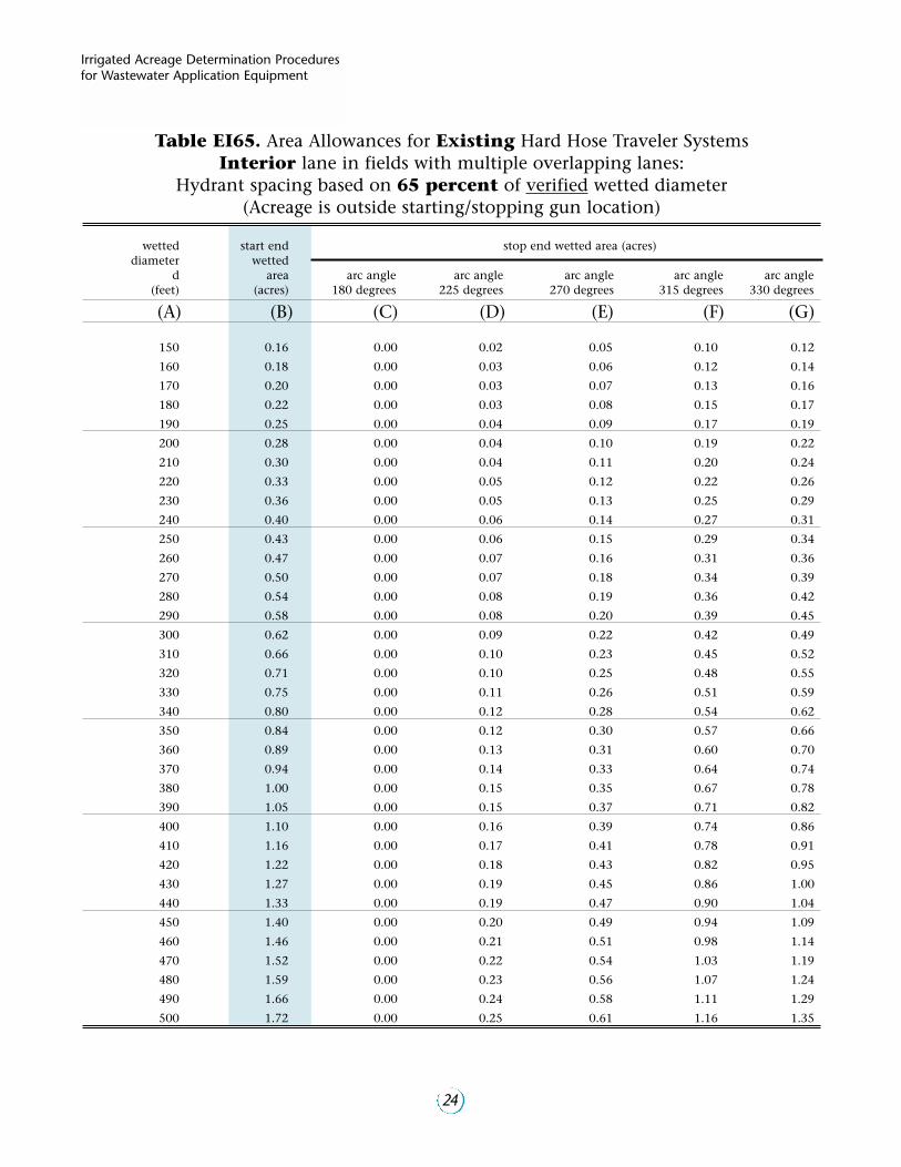
Table EI65. Area Allowances for Existing Hard Hose Traveler SystemsInterior lane in fields with multiple overlapping lanes:
Hydrant spacing based on 65 percent of verified wetted diameter(Acreage is outside starting/stopping gun location)
wetted start end stop end wetted area (acres)diameter wetted
d area arc angle arc angle arc angle arc angle arc angle(feet) (acres) 180 degrees 225 degrees 270 degrees 315 degrees 330 degrees
(A) (B) (C) (D) (E) (F) (G)
150 0.16 0.00 0.02 0.05 0.10 0.12
160 0.18 0.00 0.03 0.06 0.12 0.14
170 0.20 0.00 0.03 0.07 0.13 0.16
180 0.22 0.00 0.03 0.08 0.15 0.17
190 0.25 0.00 0.04 0.09 0.17 0.19
200 0.28 0.00 0.04 0.10 0.19 0.22
210 0.30 0.00 0.04 0.11 0.20 0.24
220 0.33 0.00 0.05 0.12 0.22 0.26
230 0.36 0.00 0.05 0.13 0.25 0.29
240 0.40 0.00 0.06 0.14 0.27 0.31
250 0.43 0.00 0.06 0.15 0.29 0.34
260 0.47 0.00 0.07 0.16 0.31 0.36
270 0.50 0.00 0.07 0.18 0.34 0.39
280 0.54 0.00 0.08 0.19 0.36 0.42
290 0.58 0.00 0.08 0.20 0.39 0.45
300 0.62 0.00 0.09 0.22 0.42 0.49
310 0.66 0.00 0.10 0.23 0.45 0.52
320 0.71 0.00 0.10 0.25 0.48 0.55
330 0.75 0.00 0.11 0.26 0.51 0.59
340 0.80 0.00 0.12 0.28 0.54 0.62
350 0.84 0.00 0.12 0.30 0.57 0.66
360 0.89 0.00 0.13 0.31 0.60 0.70
370 0.94 0.00 0.14 0.33 0.64 0.74
380 1.00 0.00 0.15 0.35 0.67 0.78
390 1.05 0.00 0.15 0.37 0.71 0.82
400 1.10 0.00 0.16 0.39 0.74 0.86
410 1.16 0.00 0.17 0.41 0.78 0.91
420 1.22 0.00 0.18 0.43 0.82 0.95
430 1.27 0.00 0.19 0.45 0.86 1.00
440 1.33 0.00 0.19 0.47 0.90 1.04
450 1.40 0.00 0.20 0.49 0.94 1.09
460 1.46 0.00 0.21 0.51 0.98 1.14
470 1.52 0.00 0.22 0.54 1.03 1.19
480 1.59 0.00 0.23 0.56 1.07 1.24
490 1.66 0.00 0.24 0.58 1.11 1.29
500 1.72 0.00 0.25 0.61 1.16 1.35
24
Irrigated Acreage Determination Proceduresfor Wastewater Application Equipment
Page 25
Table EI70. Area Allowances for Existing Hard Hose Traveler SystemsInterior lane in fields with multiple overlapping lanes:
Hydrant spacing based on 70 percent of verified wetted diameter(Acreage is outside starting/stopping gun location)
wetted start end stop end wetted area (acres)diameter wetted
d area arc angle arc angle arc angle arc angle arc angle(feet) (acres) 180 degrees 225 degrees 270 degrees 315 degrees 330 degrees
(A) (B) (C) (D) (E) (F) (G)
150 0.16 0.00 0.03 0.06 0.11 0.13
160 0.19 0.00 0.03 0.07 0.13 0.15
170 0.21 0.00 0.03 0.08 0.15 0.17
180 0.24 0.00 0.04 0.09 0.16 0.19
190 0.26 0.00 0.04 0.10 0.18 0.21
200 0.29 0.00 0.05 0.11 0.20 0.23
210 0.32 0.00 0.05 0.12 0.22 0.26
220 0.35 0.00 0.06 0.14 0.25 0.28
230 0.39 0.00 0.06 0.15 0.27 0.31
240 0.42 0.00 0.07 0.16 0.29 0.34
250 0.46 0.00 0.07 0.18 0.32 0.36
260 0.49 0.00 0.08 0.19 0.34 0.39
270 0.53 0.00 0.08 0.20 0.37 0.42
280 0.57 0.00 0.09 0.22 0.40 0.46
290 0.62 0.00 0.10 0.24 0.43 0.49
300 0.66 0.00 0.10 0.25 0.46 0.52
310 0.70 0.00 0.11 0.27 0.49 0.56
320 0.75 0.00 0.12 0.29 0.52 0.60
330 0.80 0.00 0.13 0.31 0.55 0.63
340 0.85 0.00 0.13 0.32 0.59 0.67
350 0.90 0.00 0.14 0.34 0.62 0.71
360 0.95 0.00 0.15 0.36 0.66 0.75
370 1.00 0.00 0.16 0.38 0.69 0.80
380 1.06 0.00 0.17 0.41 0.73 0.84
390 1.11 0.00 0.18 0.43 0.77 0.88
400 1.17 0.00 0.19 0.45 0.81 0.93
410 1.23 0.00 0.20 0.47 0.85 0.98
420 1.29 0.00 0.21 0.50 0.89 1.03
430 1.35 0.00 0.22 0.52 0.94 1.08
440 1.42 0.00 0.23 0.54 0.98 1.13
450 1.48 0.00 0.24 0.57 1.03 1.18
460 1.55 0.00 0.25 0.59 1.07 1.23
470 1.62 0.00 0.26 0.62 1.12 1.28
480 1.69 0.00 0.27 0.65 1.17 1.34
490 1.76 0.00 0.28 0.68 1.22 1.40
500 1.83 0.00 0.29 0.70 1.27 1.45
25
HARD HOSE TRAVELERIRRIGATION SYSTEM
Page 26
Table EI75. Area Allowances for Existing Hard Hose Traveler SystemsInterior lane in fields with multiple overlapping lanes:
Hydrant spacing based on 75 percent of verified wetted diameter(Acreage is outside starting/stopping gun location)
wetted start end stop end wetted area (acres)diameter wetted
d area arc angle arc angle arc angle arc angle arc angle(feet) (acres) 180 degrees 225 degrees 270 degrees 315 degrees 330 degrees
(A) (B) (C) (D) (E) (F) (G)
150 0.17 0.00 0.03 0.07 0.12 0.14
160 0.20 0.00 0.03 0.08 0.14 0.16
170 0.22 0.00 0.04 0.09 0.16 0.18
180 0.25 0.00 0.04 0.10 0.18 0.20
190 0.28 0.00 0.05 0.12 0.20 0.22
200 0.31 0.00 0.05 0.13 0.22 0.25
210 0.34 0.00 0.06 0.14 0.24 0.27
220 0.37 0.00 0.06 0.16 0.26 0.30
230 0.41 0.00 0.07 0.17 0.29 0.33
240 0.44 0.00 0.08 0.18 0.31 0.36
250 0.48 0.00 0.08 0.20 0.34 0.39
260 0.52 0.00 0.09 0.22 0.37 0.42
270 0.56 0.00 0.10 0.23 0.40 0.45
280 0.60 0.00 0.10 0.25 0.43 0.49
290 0.65 0.00 0.11 0.27 0.46 0.52
300 0.69 0.00 0.12 0.29 0.49 0.56
310 0.74 0.00 0.13 0.31 0.52 0.60
320 0.79 0.00 0.14 0.33 0.56 0.64
330 0.84 0.00 0.15 0.35 0.59 0.68
340 0.89 0.00 0.15 0.37 0.63 0.72
350 0.94 0.00 0.16 0.39 0.67 0.76
360 1.00 0.00 0.17 0.42 0.71 0.81
370 1.06 0.00 0.18 0.44 0.75 0.85
380 1.11 0.00 0.19 0.46 0.79 0.90
390 1.17 0.00 0.20 0.49 0.83 0.94
400 1.23 0.00 0.21 0.51 0.87 0.99
410 1.30 0.00 0.22 0.54 0.92 1.04
420 1.36 0.00 0.24 0.57 0.96 1.10
430 1.43 0.00 0.25 0.59 1.01 1.15
440 1.49 0.00 0.26 0.62 1.06 1.20
450 1.56 0.00 0.27 0.65 1.11 1.26
460 1.63 0.00 0.28 0.68 1.16 1.31
470 1.70 0.00 0.30 0.71 1.21 1.37
480 1.78 0.00 0.31 0.74 1.26 1.43
490 1.85 0.00 0.32 0.77 1.31 1.49
500 1.93 0.00 0.33 0.80 1.37 1.55
26
Irrigated Acreage Determination Proceduresfor Wastewater Application Equipment
Page 27
Table EI80. Area Allowances for Existing Hard Hose Traveler SystemsInterior lane in fields with multiple overlapping lanes:
Hydrant spacing based on 80 percent of verified wetted diameter(Acreage is outside starting/stopping gun location)
wetted start end stop end wetted area (acres)diameter wetted
d area arc angle arc angle arc angle arc angle arc angle(feet) (acres) 180 degrees 225 degrees 270 degrees 315 degrees 330 degrees
(A) (B) (C) (D) (E) (F) (G)
150 0.18 0.00 0.03 0.08 0.13 0.15
160 0.21 0.00 0.04 0.09 0.15 0.17
170 0.23 0.00 0.04 0.10 0.17 0.19
180 0.26 0.00 0.05 0.12 0.19 0.21
190 0.29 0.00 0.05 0.13 0.21 0.24
200 0.32 0.00 0.06 0.14 0.23 0.26
210 0.36 0.00 0.07 0.16 0.26 0.29
220 0.39 0.00 0.07 0.17 0.28 0.32
230 0.43 0.00 0.08 0.19 0.31 0.35
240 0.47 0.00 0.09 0.21 0.34 0.38
250 0.50 0.00 0.10 0.22 0.36 0.41
260 0.55 0.00 0.10 0.24 0.39 0.44
270 0.59 0.00 0.11 0.26 0.42 0.48
280 0.63 0.00 0.12 0.28 0.46 0.52
290 0.68 0.00 0.13 0.30 0.49 0.55
300 0.73 0.00 0.14 0.32 0.52 0.59
310 0.78 0.00 0.15 0.34 0.56 0.63
320 0.83 0.00 0.16 0.37 0.60 0.67
330 0.88 0.00 0.17 0.39 0.63 0.72
340 0.93 0.00 0.18 0.41 0.67 0.76
350 0.99 0.00 0.19 0.44 0.71 0.81
360 1.05 0.00 0.20 0.46 0.75 0.85
370 1.11 0.00 0.21 0.49 0.80 0.90
380 1.17 0.00 0.22 0.52 0.84 0.95
390 1.23 0.00 0.23 0.54 0.89 1.00
400 1.29 0.00 0.24 0.57 0.93 1.05
410 1.36 0.00 0.26 0.60 0.98 1.11
420 1.42 0.00 0.27 0.63 1.03 1.16
430 1.49 0.00 0.28 0.66 1.08 1.22
440 1.56 0.00 0.29 0.69 1.13 1.27
450 1.64 0.00 0.31 0.72 1.18 1.33
460 1.71 0.00 0.32 0.76 1.23 1.39
470 1.78 0.00 0.34 0.79 1.29 1.45
480 1.86 0.00 0.35 0.82 1.34 1.51
490 1.94 0.00 0.37 0.86 1.40 1.58
500 2.02 0.00 0.38 0.89 1.46 1.64
27
HARD HOSE TRAVELERIRRIGATION SYSTEM
Page 28
Table EI85. Area Allowances for Existing Hard Hose Traveler SystemsInterior lane in fields with multiple overlapping lanes:
Hydrant spacing based on 85 percent of verified wetted diameter(Acreage is outside starting/stopping gun location)
wetted start end stop end wetted area (acres)diameter wetted
d area arc angle arc angle arc angle arc angle arc angle(feet) (acres) 180 degrees 225 degrees 270 degrees 315 degrees 330 degrees
(A) (B) (C) (D) (E) (F) (G)
150 0.19 0.00 0.04 0.09 0.14 0.16
160 0.22 0.00 0.04 0.10 0.16 0.18
170 0.24 0.00 0.05 0.11 0.18 0.20
180 0.27 0.00 0.06 0.13 0.20 0.22
200 0.34 0.00 0.07 0.16 0.25 0.28
210 0.37 0.00 0.08 0.17 0.27 0.30
220 0.41 0.00 0.08 0.19 0.30 0.33
230 0.44 0.00 0.09 0.21 0.33 0.36
240 0.48 0.00 0.10 0.22 0.35 0.40
250 0.53 0.00 0.11 0.24 0.38 0.43
260 0.57 0.00 0.12 0.26 0.42 0.47
270 0.61 0.00 0.13 0.28 0.45 0.50
280 0.66 0.00 0.13 0.31 0.48 0.54
290 0.71 0.00 0.14 0.33 0.52 0.58
300 0.76 0.00 0.15 0.35 0.55 0.62
310 0.81 0.00 0.17 0.37 0.59 0.66
320 0.86 0.00 0.18 0.40 0.63 0.71
330 0.91 0.00 0.19 0.42 0.67 0.75
340 0.97 0.00 0.20 0.45 0.71 0.80
350 1.03 0.00 0.21 0.48 0.75 0.85
360 1.09 0.00 0.22 0.50 0.80 0.89
370 1.15 0.00 0.24 0.53 0.84 0.94
380 1.21 0.00 0.25 0.56 0.89 1.00
390 1.28 0.00 0.26 0.59 0.94 1.05
400 1.34 0.00 0.27 0.62 0.98 1.10
410 1.41 0.00 0.29 0.65 1.03 1.16
420 1.48 0.00 0.30 0.69 1.08 1.22
430 1.55 0.00 0.32 0.72 1.14 1.28
440 1.63 0.00 0.33 0.75 1.19 1.34
450 1.70 0.00 0.35 0.79 1.24 1.40
460 1.78 0.00 0.36 0.82 1.30 1.46
470 1.86 0.00 0.38 0.86 1.36 1.52
480 1.94 0.00 0.40 0.90 1.42 1.59
490 2.02 0.00 0.41 0.93 1.48 1.66
500 2.10 0.00 0.43 0.97 1.54 1.72
28
Irrigated Acreage Determination Proceduresfor Wastewater Application Equipment
Page 29
Table EI90. Area Allowances for Existing Hard Hose Traveler SystemsInterior lane in fields with multiple overlapping lanes:
Hydrant spacing based on 90 percent of verified wetted diameter(Acreage is outside starting/stopping gun location)
wetted start end stop end wetted area (acres)diameter wetted
d area arc angle arc angle arc angle arc angle arc angle(feet) (acres) 180 degrees 225 degrees 270 degrees 315 degrees 330 degrees
(A) (B) (C) (D) (E) (F) (G)
150 0.20 0.00 0.04 0.09 0.14 0.16
160 0.22 0.00 0.05 0.11 0.16 0.18
170 0.25 0.00 0.06 0.12 0.19 0.21
180 0.28 0.00 0.06 0.14 0.21 0.23
190 0.31 0.00 0.07 0.15 0.23 0.26
200 0.35 0.00 0.08 0.17 0.26 0.29
210 0.38 0.00 0.08 0.18 0.28 0.32
220 0.42 0.00 0.09 0.20 0.31 0.35
230 0.46 0.00 0.10 0.22 0.34 0.38
240 0.50 0.00 0.11 0.24 0.37 0.41
250 0.54 0.00 0.12 0.26 0.40 0.45
260 0.59 0.00 0.13 0.28 0.43 0.49
270 0.63 0.00 0.14 0.30 0.47 0.52
280 0.68 0.00 0.15 0.33 0.50 0.56
290 0.73 0.00 0.16 0.35 0.54 0.60
300 0.78 0.00 0.17 0.38 0.58 0.65
310 0.83 0.00 0.19 0.40 0.62 0.69
320 0.89 0.00 0.20 0.43 0.66 0.73
330 0.95 0.00 0.21 0.45 0.70 0.78
340 1.00 0.00 0.22 0.48 0.74 0.83
350 1.06 0.00 0.24 0.51 0.79 0.88
360 1.12 0.00 0.25 0.54 0.83 0.93
370 1.19 0.00 0.26 0.57 0.88 0.98
380 1.25 0.00 0.28 0.60 0.93 1.04
390 1.32 0.00 0.29 0.63 0.98 1.09
400 1.39 0.00 0.31 0.67 1.03 1.15
410 1.46 0.00 0.32 0.70 1.08 1.21
420 1.53 0.00 0.34 0.74 1.13 1.27
430 1.60 0.00 0.36 0.77 1.19 1.33
440 1.68 0.00 0.37 0.81 1.24 1.39
450 1.76 0.00 0.39 0.84 1.30 1.45
460 1.84 0.00 0.41 0.88 1.36 1.52
470 1.92 0.00 0.43 0.92 1.42 1.59
480 2.00 0.00 0.44 0.96 1.48 1.65
490 2.08 0.00 0.46 1.00 1.54 1.72
500 2.17 0.00 0.48 1.04 1.61 1.79
29
HARD HOSE TRAVELERIRRIGATION SYSTEM
Page 30
Table E90+. Area Allowances for Existing Hard Hose Traveler SystemsFields with single pull or multiple pulls and
Hydrant spacing greater than 90 percent of verified wetted diameter(Acreage is outside starting/stopping gun location)
wetted start end stop end wetted area (acres)diameter wetted
d area arc angle arc angle arc angle arc angle arc angle(feet) (acres) 180 degrees 225 degrees 270 degrees 315 degrees 330 degrees
(A) (B) (C) (D) (E) (F) (G)
150 0.16 0.00 0.04 0.08 0.12 0.14
160 0.19 0.00 0.05 0.09 0.14 0.16
170 0.21 0.00 0.05 0.11 0.16 0.18
180 0.24 0.00 0.06 0.12 0.18 0.20
190 0.26 0.00 0.07 0.13 0.20 0.22
200 0.29 0.00 0.07 0.15 0.22 0.24
210 0.32 0.00 0.08 0.16 0.24 0.27
220 0.35 0.00 0.09 0.18 0.27 0.29
230 0.39 0.00 0.10 0.19 0.29 0.32
240 0.42 0.00 0.11 0.21 0.32 0.35
250 0.46 0.00 0.11 0.23 0.34 0.38
260 0.49 0.00 0.12 0.25 0.37 0.41
270 0.53 0.00 0.13 0.27 0.40 0.44
280 0.57 0.00 0.14 0.29 0.43 0.48
290 0.61 0.00 0.15 0.31 0.46 0.51
300 0.66 0.00 0.16 0.33 0.49 0.55
310 0.70 0.00 0.18 0.35 0.53 0.58
320 0.75 0.00 0.19 0.37 0.56 0.62
330 0.80 0.00 0.20 0.40 0.60 0.66
340 0.84 0.00 0.21 0.42 0.63 0.70
350 0.89 0.00 0.22 0.45 0.67 0.75
360 0.95 0.00 0.24 0.47 0.71 0.79
370 1.00 0.00 0.25 0.50 0.75 0.83
380 1.05 0.00 0.26 0.53 0.79 0.88
390 1.11 0.00 0.28 0.56 0.83 0.93
400 1.17 0.00 0.29 0.58 0.88 0.97
410 1.23 0.00 0.31 0.61 0.92 1.02
420 1.29 0.00 0.32 0.64 0.97 1.07
430 1.35 0.00 0.34 0.68 1.01 1.13
440 1.41 0.00 0.35 0.71 1.06 1.18
450 1.48 0.00 0.37 0.74 1.11 1.23
460 1.55 0.00 0.39 0.77 1.16 1.29
470 1.61 0.00 0.40 0.81 1.21 1.34
480 1.68 0.00 0.42 0.84 1.26 1.40
490 1.75 0.00 0.44 0.88 1.32 1.46
500 1.83 0.00 0.46 0.91 1.37 1.52
30
Irrigated Acreage Determination Proceduresfor Wastewater Application Equipment
Page 31
31
HARD HOSE TRAVELERIRRIGATION SYSTEM
Table NE60. Area Allowances for New or Expanded Hard Hose Traveler SystemsExterior lane in fields with multiple overlapping lanes:
Hydrant spacing based on 60 percent of wetted diameter(Acreage is outside starting/stopping gun location)
wetted start end stop end wetted area (acres)diameter wetted
d area arc angle arc angle arc angle arc angle arc angle(feet) (acres) 180 degrees 225 degrees 270 degrees 315 degrees 330 degrees
(A) (B) (C) (D) (E) (F) (G)
150 0.12 0.00 0.03 0.05 0.08 0.09
160 0.13 0.00 0.03 0.06 0.10 0.11
170 0.15 0.00 0.03 0.07 0.11 0.12
180 0.17 0.00 0.04 0.08 0.12 0.14
190 0.19 0.00 0.04 0.09 0.14 0.15
200 0.21 0.00 0.04 0.10 0.15 0.17
210 0.23 0.00 0.05 0.11 0.17 0.19
220 0.25 0.00 0.05 0.12 0.18 0.20
230 0.27 0.00 0.06 0.13 0.20 0.22
240 0.30 0.00 0.06 0.14 0.22 0.24
250 0.32 0.00 0.07 0.15 0.24 0.26
260 0.35 0.00 0.08 0.16 0.25 0.29
270 0.37 0.00 0.08 0.17 0.27 0.31
280 0.40 0.00 0.09 0.19 0.29 0.33
290 0.43 0.00 0.09 0.20 0.32 0.35
300 0.46 0.00 0.10 0.22 0.34 0.38
310 0.49 0.00 0.11 0.23 0.36 0.41
320 0.53 0.00 0.11 0.24 0.39 0.43
330 0.56 0.00 0.12 0.26 0.41 0.46
340 0.59 0.00 0.13 0.28 0.43 0.49
350 0.63 0.00 0.14 0.29 0.46 0.52
360 0.67 0.00 0.14 0.31 0.49 0.55
370 0.70 0.00 0.15 0.33 0.51 0.58
380 0.74 0.00 0.16 0.35 0.54 0.61
390 0.78 0.00 0.17 0.36 0.57 0.64
400 0.82 0.00 0.18 0.38 0.60 0.68
410 0.86 0.00 0.19 0.40 0.63 0.71
420 0.91 0.00 0.20 0.42 0.66 0.74
430 0.95 0.00 0.21 0.44 0.70 0.78
440 0.99 0.00 0.22 0.46 0.73 0.82
450 1.04 0.00 0.23 0.48 0.76 0.85
460 1.09 0.00 0.24 0.51 0.80 0.89
470 1.13 0.00 0.25 0.53 0.83 0.93
480 1.18 0.00 0.26 0.55 0.87 0.97
490 1.23 0.00 0.27 0.57 0.90 1.01
500 1.28 0.00 0.28 0.60 0.94 1.05
Page 32
32
Irrigated Acreage Determination Proceduresfor Wastewater Application Equipment
Table NE65. Area Allowances for New or Expanded Hard Hose Traveler SystemsExterior lane in fields with multiple overlapping lanes:
Hydrant spacing based on 65 percent of wetted diameter(Acreage is outside starting/stopping gun location)
wetted start end stop end wetted area (acres)diameter wetted
d area arc angle arc angle arc angle arc angle arc angle(feet) (acres) 180 degrees 225 degrees 270 degrees 315 degrees 330 degrees
(A) (B) (C) (D) (E) (F) (G)
150 0.12 0.00 0.03 0.06 0.09 0.10
160 0.13 0.00 0.03 0.06 0.10 0.11
170 0.15 0.00 0.03 0.07 0.11 0.13
180 0.17 0.00 0.04 0.08 0.13 0.14
190 0.19 0.00 0.04 0.09 0.14 0.16
200 0.21 0.00 0.05 0.10 0.16 0.17
210 0.23 0.00 0.05 0.11 0.17 0.19
220 0.25 0.00 0.06 0.12 0.19 0.21
230 0.28 0.00 0.06 0.13 0.21 0.23
240 0.30 0.00 0.07 0.15 0.22 0.25
250 0.33 0.00 0.07 0.16 0.24 0.27
260 0.36 0.00 0.08 0.17 0.26 0.29
270 0.38 0.00 0.09 0.18 0.28 0.32
280 0.41 0.00 0.09 0.20 0.31 0.34
290 0.44 0.00 0.10 0.21 0.33 0.37
300 0.47 0.00 0.11 0.23 0.35 0.39
310 0.51 0.00 0.11 0.24 0.37 0.42
320 0.54 0.00 0.12 0.26 0.40 0.45
330 0.57 0.00 0.13 0.27 0.42 0.47
340 0.61 0.00 0.14 0.29 0.45 0.50
350 0.65 0.00 0.15 0.31 0.48 0.53
360 0.68 0.00 0.15 0.33 0.50 0.56
370 0.72 0.00 0.16 0.35 0.53 0.60
380 0.76 0.00 0.17 0.36 0.56 0.63
390 0.80 0.00 0.18 0.38 0.59 0.66
400 0.84 0.00 0.19 0.40 0.62 0.70
410 0.89 0.00 0.20 0.42 0.65 0.73
420 0.93 0.00 0.21 0.45 0.69 0.77
430 0.97 0.00 0.22 0.47 0.72 0.80
440 1.02 0.00 0.23 0.49 0.75 0.84
450 1.07 0.00 0.24 0.51 0.79 0.88
460 1.11 0.00 0.25 0.53 0.82 0.92
470 1.16 0.00 0.26 0.56 0.86 0.96
480 1.21 0.00 0.27 0.58 0.90 1.00
490 1.26 0.00 0.29 0.61 0.94 1.05
500 1.32 0.00 0.30 0.63 0.97 1.09
Page 33
Table NE70. Area Allowances for New or Expanded Hard Hose Traveler SystemsExterior lane in fields with multiple overlapping lanes:
Hydrant spacing based on 70 percent of wetted diameter(Acreage is outside starting/stopping gun location)
wetted start end stop end wetted area (acres)diameter wetted
d area arc angle arc angle arc angle arc angle arc angle(feet) (acres) 180 degrees 225 degrees 270 degrees 315 degrees 330 degrees
(A) (B) (C) (D) (E) (F) (G)
150 0.12 0.00 0.03 0.06 0.09 0.10
160 0.14 0.00 0.03 0.07 0.10 0.11
170 0.16 0.00 0.04 0.08 0.12 0.13
180 0.17 0.00 0.04 0.09 0.13 0.14
190 0.19 0.00 0.05 0.10 0.14 0.16
200 0.22 0.00 0.05 0.11 0.16 0.18
210 0.24 0.00 0.06 0.12 0.18 0.20
220 0.26 0.00 0.06 0.13 0.19 0.22
230 0.28 0.00 0.07 0.14 0.21 0.24
240 0.31 0.00 0.07 0.15 0.23 0.26
250 0.34 0.00 0.08 0.16 0.25 0.28
260 0.36 0.00 0.09 0.18 0.27 0.30
270 0.39 0.00 0.09 0.19 0.29 0.33
280 0.42 0.00 0.10 0.21 0.31 0.35
290 0.45 0.00 0.11 0.22 0.34 0.38
300 0.48 0.00 0.11 0.24 0.36 0.40
310 0.52 0.00 0.12 0.25 0.39 0.43
320 0.55 0.00 0.13 0.27 0.41 0.46
330 0.59 0.00 0.14 0.29 0.44 0.49
340 0.62 0.00 0.15 0.30 0.46 0.52
350 0.66 0.00 0.16 0.32 0.49 0.55
360 0.70 0.00 0.16 0.34 0.52 0.58
370 0.74 0.00 0.17 0.36 0.55 0.61
380 0.78 0.00 0.18 0.38 0.58 0.64
390 0.82 0.00 0.19 0.40 0.61 0.68
400 0.86 0.00 0.20 0.42 0.64 0.71
410 0.90 0.00 0.21 0.44 0.67 0.75
420 0.95 0.00 0.22 0.46 0.71 0.79
430 0.99 0.00 0.23 0.49 0.74 0.83
440 1.04 0.00 0.25 0.51 0.78 0.86
450 1.09 0.00 0.26 0.53 0.81 0.90
460 1.14 0.00 0.27 0.56 0.85 0.94
470 1.19 0.00 0.28 0.58 0.89 0.99
480 1.24 0.00 0.29 0.61 0.92 1.03
490 1.29 0.00 0.30 0.63 0.96 1.07
500 1.34 0.00 0.32 0.66 1.00 1.12
33
HARD HOSE TRAVELERIRRIGATION SYSTEM
Page 34
Table NE75. Area Allowances for New or Expanded Hard Hose Traveler SystemsExterior lane in fields with multiple overlapping lanes:
Hydrant spacing based on 75 percent of wetted diameter(Acreage is outside starting/stopping gun location)
wetted start end stop end wetted area (acres)diameter wetted
d area arc angle arc angle arc angle arc angle arc angle(feet) (acres) 180 degrees 225 degrees 270 degrees 315 degrees 330 degrees
(A) (B) (C) (D) (E) (F) (G)
150 0.12 0.00 0.03 0.06 0.09 0.10
160 0.14 0.00 0.03 0.07 0.10 0.12
170 0.16 0.00 0.04 0.08 0.12 0.13
180 0.18 0.00 0.04 0.09 0.13 0.15
190 0.20 0.00 0.05 0.10 0.15 0.16
200 0.22 0.00 0.05 0.11 0.16 0.18
210 0.24 0.00 0.06 0.12 0.18 0.20
220 0.26 0.00 0.07 0.13 0.20 0.22
230 0.29 0.00 0.07 0.14 0.22 0.24
240 0.31 0.00 0.08 0.16 0.24 0.26
250 0.34 0.00 0.08 0.17 0.26 0.28
260 0.37 0.00 0.09 0.18 0.28 0.31
270 0.40 0.00 0.10 0.20 0.30 0.33
280 0.43 0.00 0.11 0.21 0.32 0.36
290 0.46 0.00 0.11 0.23 0.34 0.38
300 0.49 0.00 0.12 0.24 0.37 0.41
310 0.52 0.00 0.13 0.26 0.39 0.44
320 0.56 0.00 0.14 0.28 0.42 0.47
330 0.59 0.00 0.15 0.30 0.45 0.50
340 0.63 0.00 0.16 0.31 0.47 0.53
350 0.67 0.00 0.16 0.33 0.50 0.56
360 0.71 0.00 0.17 0.35 0.53 0.59
370 0.75 0.00 0.18 0.37 0.56 0.62
380 0.79 0.00 0.19 0.39 0.59 0.66
390 0.83 0.00 0.20 0.41 0.62 0.69
400 0.87 0.00 0.22 0.43 0.65 0.73
410 0.92 0.00 0.23 0.46 0.69 0.76
420 0.96 0.00 0.24 0.48 0.72 0.80
430 1.01 0.00 0.25 0.50 0.76 0.84
440 1.06 0.00 0.26 0.53 0.79 0.88
450 1.11 0.00 0.27 0.55 0.83 0.92
460 1.16 0.00 0.28 0.58 0.87 0.96
470 1.21 0.00 0.30 0.60 0.90 1.00
480 1.26 0.00 0.31 0.63 0.94 1.05
490 1.31 0.00 0.32 0.65 0.98 1.09
500 1.37 0.00 0.34 0.68 1.02 1.14
34
Irrigated Acreage Determination Proceduresfor Wastewater Application Equipment
Page 35
Table NI60. Area Allowances for New or Expanded Hard Hose Traveler SystemsInterior lane in fields with multiple overlapping lanes:
Hydrant spacing based on 60 percent of wetted diameter(Acreage is outside starting/stopping gun location)
wetted start end stop end wetted area (acres)diameter wetted
d area arc angle arc angle arc angle arc angle arc angle(feet) (acres) 180 degrees 225 degrees 270 degrees 315 degrees 330 degrees
(A) (B) (C) (D) (E) (F) (G)
150 0.11 0.00 0.02 0.05 0.08 0.09
160 0.12 0.00 0.02 0.05 0.09 0.10
170 0.14 0.00 0.02 0.06 0.10 0.11
180 0.15 0.00 0.03 0.07 0.11 0.13
190 0.17 0.00 0.03 0.07 0.12 0.14
200 0.19 0.00 0.03 0.08 0.14 0.15
210 0.21 0.00 0.04 0.09 0.15 0.17
220 0.23 0.00 0.04 0.10 0.17 0.19
230 0.25 0.00 0.05 0.11 0.18 0.20
240 0.28 0.00 0.05 0.12 0.20 0.22
250 0.30 0.00 0.05 0.13 0.21 0.24
260 0.32 0.00 0.06 0.14 0.23 0.26
270 0.35 0.00 0.06 0.15 0.25 0.28
280 0.37 0.00 0.07 0.16 0.27 0.30
290 0.40 0.00 0.07 0.17 0.29 0.33
300 0.43 0.00 0.08 0.18 0.31 0.35
310 0.46 0.00 0.08 0.20 0.33 0.37
320 0.49 0.00 0.09 0.21 0.35 0.40
330 0.52 0.00 0.09 0.22 0.37 0.42
340 0.55 0.00 0.10 0.24 0.39 0.45
350 0.59 0.00 0.10 0.25 0.42 0.47
360 0.62 0.00 0.11 0.26 0.44 0.50
370 0.65 0.00 0.12 0.28 0.47 0.53
380 0.69 0.00 0.12 0.29 0.49 0.56
390 0.73 0.00 0.13 0.31 0.52 0.59
400 0.76 0.00 0.14 0.33 0.55 0.62
410 0.80 0.00 0.14 0.34 0.57 0.65
420 0.84 0.00 0.15 0.36 0.60 0.68
430 0.88 0.00 0.16 0.38 0.63 0.71
440 0.93 0.00 0.17 0.39 0.66 0.75
450 0.97 0.00 0.17 0.41 0.69 0.78
460 1.01 0.00 0.18 0.43 0.72 0.82
470 1.06 0.00 0.19 0.45 0.75 0.85
480 1.10 0.00 0.20 0.47 0.79 0.89
490 1.15 0.00 0.21 0.49 0.82 0.93
500 1.20 0.00 0.21 0.51 0.85 0.97
35
HARD HOSE TRAVELERIRRIGATION SYSTEM
Page 36
Table NI65. Area Allowances for New or Expanded Hard Hose Traveler SystemsInterior lane in fields with multiple overlapping lanes:
Hydrant spacing based on 65 percent of wetted diameter(Acreage is outside starting/stopping gun location)
wetted start end stop end wetted area (acres)diameter wetted
d area arc angle arc angle arc angle arc angle arc angle(feet) (acres) 180 degrees 225 degrees 270 degrees 315 degrees 330 degrees
(A) (B) (C) (D) (E) (F) (G)
150 0.11 0.00 0.02 0.05 0.08 0.09
160 0.13 0.00 0.03 0.06 0.09 0.11
170 0.15 0.00 0.03 0.07 0.11 0.12
180 0.16 0.00 0.03 0.07 0.12 0.13
190 0.18 0.00 0.04 0.08 0.13 0.15
200 0.20 0.00 0.04 0.09 0.15 0.17
210 0.22 0.00 0.04 0.10 0.16 0.18
220 0.24 0.00 0.05 0.11 0.18 0.20
230 0.27 0.00 0.05 0.12 0.19 0.22
240 0.29 0.00 0.06 0.13 0.21 0.24
250 0.32 0.00 0.06 0.14 0.23 0.26
260 0.34 0.00 0.07 0.16 0.25 0.28
270 0.37 0.00 0.07 0.17 0.27 0.30
280 0.40 0.00 0.08 0.18 0.29 0.32
290 0.42 0.00 0.08 0.19 0.31 0.35
300 0.45 0.00 0.09 0.21 0.33 0.37
310 0.49 0.00 0.10 0.22 0.35 0.40
320 0.52 0.00 0.10 0.24 0.38 0.42
330 0.55 0.00 0.11 0.25 0.40 0.45
340 0.58 0.00 0.12 0.27 0.43 0.48
350 0.62 0.00 0.12 0.28 0.45 0.51
360 0.65 0.00 0.13 0.30 0.48 0.54
370 0.69 0.00 0.14 0.32 0.50 0.57
380 0.73 0.00 0.15 0.33 0.53 0.60
390 0.77 0.00 0.15 0.35 0.56 0.63
400 0.81 0.00 0.16 0.37 0.59 0.66
410 0.85 0.00 0.17 0.39 0.62 0.69
420 0.89 0.00 0.18 0.41 0.65 0.73
430 0.93 0.00 0.19 0.43 0.68 0.76
440 0.98 0.00 0.19 0.45 0.71 0.80
450 1.02 0.00 0.20 0.47 0.74 0.84
460 1.07 0.00 0.21 0.49 0.78 0.87
470 1.12 0.00 0.22 0.51 0.81 0.91
480 1.16 0.00 0.23 0.53 0.85 0.95
490 1.21 0.00 0.24 0.55 0.88 0.99
500 1.26 0.00 0.25 0.58 0.92 1.03
36
Irrigated Acreage Determination Proceduresfor Wastewater Application Equipment
Page 37
Table NI70. Area Allowances for New or Expanded Hard Hose Traveler SystemsInterior lane in fields with multiple overlapping lanes:
Hydrant spacing based on 70 percent of wetted diameter(Acreage is outside starting/stopping gun location)
wetted start end stop end wetted area (acres)diameter wetted
d area arc angle arc angle arc angle arc angle arc angle(feet) (acres) 180 degrees 225 degrees 270 degrees 315 degrees 330 degrees
(A) (B) (C) (D) (E) (F) (G)
150 0.12 0.00 0.03 0.06 0.09 0.10
160 0.13 0.00 0.03 0.06 0.10 0.11
170 0.15 0.00 0.03 0.07 0.11 0.13
180 0.17 0.00 0.04 0.08 0.13 0.14
190 0.19 0.00 0.04 0.09 0.14 0.16
200 0.21 0.00 0.05 0.10 0.16 0.17
210 0.23 0.00 0.05 0.11 0.17 0.19
220 0.26 0.00 0.06 0.12 0.19 0.21
230 0.28 0.00 0.06 0.13 0.21 0.23
240 0.30 0.00 0.07 0.15 0.22 0.25
250 0.33 0.00 0.07 0.16 0.24 0.27
260 0.36 0.00 0.08 0.17 0.26 0.29
270 0.38 0.00 0.08 0.18 0.28 0.32
280 0.41 0.00 0.09 0.20 0.31 0.34
290 0.44 0.00 0.10 0.21 0.33 0.37
300 0.47 0.00 0.10 0.23 0.35 0.39
310 0.51 0.00 0.11 0.24 0.37 0.42
320 0.54 0.00 0.12 0.26 0.40 0.45
330 0.57 0.00 0.13 0.28 0.42 0.47
340 0.61 0.00 0.13 0.29 0.45 0.50
350 0.65 0.00 0.14 0.31 0.48 0.53
360 0.68 0.00 0.15 0.33 0.51 0.56
370 0.72 0.00 0.16 0.35 0.53 0.60
380 0.76 0.00 0.17 0.37 0.56 0.63
390 0.80 0.00 0.18 0.38 0.59 0.66
400 0.84 0.00 0.19 0.40 0.62 0.70
410 0.89 0.00 0.20 0.43 0.66 0.73
420 0.93 0.00 0.21 0.45 0.69 0.77
430 0.97 0.00 0.22 0.47 0.72 0.81
440 1.02 0.00 0.23 0.49 0.76 0.84
450 1.07 0.00 0.24 0.51 0.79 0.88
460 1.12 0.00 0.25 0.54 0.83 0.92
470 1.16 0.00 0.26 0.56 0.86 0.96
480 1.21 0.00 0.27 0.58 0.90 1.00
490 1.27 0.00 0.28 0.61 0.94 1.05
500 1.32 0.00 0.29 0.63 0.98 1.09
37
HARD HOSE TRAVELERIRRIGATION SYSTEM
Page 38
Table NI75. Area Allowances for New or Expanded Hard Hose Traveler SystemsInterior lane in fields with multiple overlapping lanes:
Hydrant spacing based on 75 percent of wetted diameter(Acreage is outside starting/stopping gun location)
wetted start end stop end wetted area (acres)diameter wetted
d area arc angle arc angle arc angle arc angle arc angle(feet) (acres) 180 degrees 225 degrees 270 degrees 315 degrees 330 degrees
(A) (B) (C) (D) (E) (F) (G)
150 0.12 0.00 0.03 0.06 0.09 0.10
160 0.14 0.00 0.03 0.07 0.10 0.12
170 0.16 0.00 0.04 0.08 0.12 0.13
180 0.18 0.00 0.04 0.09 0.13 0.15
190 0.20 0.00 0.05 0.10 0.15 0.16
200 0.22 0.00 0.05 0.11 0.16 0.18
210 0.24 0.00 0.06 0.12 0.18 0.20
220 0.26 0.00 0.06 0.13 0.20 0.22
230 0.29 0.00 0.07 0.14 0.22 0.24
240 0.31 0.00 0.08 0.16 0.23 0.26
250 0.34 0.00 0.08 0.17 0.25 0.28
260 0.37 0.00 0.09 0.18 0.27 0.31
270 0.40 0.00 0.10 0.20 0.30 0.33
280 0.43 0.00 0.10 0.21 0.32 0.35
290 0.46 0.00 0.11 0.23 0.34 0.38
300 0.49 0.00 0.12 0.24 0.37 0.41
310 0.52 0.00 0.13 0.26 0.39 0.43
320 0.56 0.00 0.14 0.28 0.42 0.46
330 0.59 0.00 0.14 0.29 0.44 0.49
340 0.63 0.00 0.15 0.31 0.47 0.52
350 0.67 0.00 0.16 0.33 0.50 0.55
360 0.70 0.00 0.17 0.35 0.53 0.59
370 0.74 0.00 0.18 0.37 0.56 0.62
380 0.78 0.00 0.19 0.39 0.59 0.65
390 0.83 0.00 0.20 0.41 0.62 0.69
400 0.87 0.00 0.21 0.43 0.65 0.72
410 0.91 0.00 0.22 0.45 0.68 0.76
420 0.96 0.00 0.23 0.48 0.72 0.80
430 1.01 0.00 0.24 0.50 0.75 0.84
440 1.05 0.00 0.26 0.52 0.79 0.88
450 1.10 0.00 0.27 0.55 0.82 0.92
460 1.15 0.00 0.28 0.57 0.86 0.96
470 1.20 0.00 0.29 0.59 0.90 1.00
480 1.25 0.00 0.30 0.62 0.94 1.04
490 1.31 0.00 0.32 0.65 0.98 1.09
500 1.36 0.00 0.33 0.67 1.02 1.13
38
Irrigated Acreage Determination Proceduresfor Wastewater Application Equipment
Page 39
Table N75+. Area Allowances for New or Expanded Hard Hose Traveler SystemsExterior or Interior lane in fields with single pull or:
Hydrant spacing greater than 75 percent of wetted diameter(Acreage is outside starting/stopping gun location)
wetted start end stop end wetted area (acres)diameter wetted
d area arc angle arc angle arc angle arc angle arc angle(feet) (acres) 180 degrees 225 degrees 270 degrees 315 degrees 330 degrees
(A) (B) (C) (D) (E) (F) (G)
150 0.12 0.00 0.03 0.06 0.09 0.10
160 0.14 0.00 0.04 0.07 0.11 0.12
170 0.16 0.00 0.04 0.08 0.12 0.13
180 0.18 0.00 0.04 0.09 0.13 0.15
190 0.20 0.00 0.05 0.10 0.15 0.17
200 0.22 0.00 0.05 0.11 0.16 0.18
210 0.24 0.00 0.06 0.12 0.18 0.20
220 0.27 0.00 0.07 0.13 0.20 0.22
230 0.29 0.00 0.07 0.15 0.22 0.24
240 0.32 0.00 0.08 0.16 0.24 0.26
250 0.34 0.00 0.09 0.17 0.26 0.29
260 0.37 0.00 0.09 0.19 0.28 0.31
270 0.40 0.00 0.10 0.20 0.30 0.33
280 0.43 0.00 0.11 0.22 0.32 0.36
290 0.46 0.00 0.12 0.23 0.35 0.38
300 0.49 0.00 0.12 0.25 0.37 0.41
310 0.53 0.00 0.13 0.26 0.40 0.44
320 0.56 0.00 0.14 0.28 0.42 0.47
330 0.60 0.00 0.15 0.30 0.45 0.50
340 0.63 0.00 0.16 0.32 0.48 0.53
350 0.67 0.00 0.17 0.34 0.50 0.56
360 0.71 0.00 0.18 0.36 0.53 0.59
370 0.75 0.00 0.19 0.38 0.56 0.63
380 0.79 0.00 0.20 0.40 0.59 0.66
390 0.83 0.00 0.21 0.42 0.63 0.70
400 0.88 0.00 0.22 0.44 0.66 0.73
410 0.92 0.00 0.23 0.46 0.69 0.77
420 0.97 0.00 0.24 0.48 0.73 0.81
430 1.01 0.00 0.25 0.51 0.76 0.85
440 1.06 0.00 0.27 0.53 0.80 0.88
450 1.11 0.00 0.28 0.56 0.83 0.93
460 1.16 0.00 0.29 0.58 0.87 0.97
470 1.21 0.00 0.30 0.61 0.91 1.01
480 1.26 0.00 0.32 0.63 0.95 1.05
490 1.32 0.00 0.33 0.66 0.99 1.10
500 1.37 0.00 0.34 0.69 1.03 1.14
39
HARD HOSE TRAVELERIRRIGATION SYSTEM
Page 40
Prepared by
Robert 0. Evans, PE; Biological and Agricultural Engineering Associate Professor
Ronald E. Sneed, PE, CID; Biological and Agricultural Engineering Professor, Emeritus
Ron E. Sheffield, Biological and Agricultural Engineering Extension Specialist
Jonathan T. Smith, Biological and Agricultural Engineering Extension Assistant
2,000 copies of this public document were printed at a cost of $5805.70 or $2.90 per copy.
Published byNORTH CAROLINA COOPERATIVE EXTENSION SERVICE
Distributed in furtherance of the Acts of Congress of May 8 and June 30, 1914. Employment and program opportunities are offered to all people regardless of race, color, national origin, sex, age, or disability. North Carolina State University, North Carolina A&T State University, U.S.Department of Agriculture, and local governments cooperating.5/99-2M-DSB AG-553-7E99-39144