Date post: | 07-Apr-2018 |
Category: |
Documents |
Upload: | ppareek16892 |
View: | 221 times |
Download: | 0 times |
8/4/2019 Hariharan Book
http://slidepdf.com/reader/full/hariharan-book 1/10
1
Holographic imaging
A hologram is usually recorded on a photographic plate or a flat piece of film,
but produces a three-dimensional image. In addition, making a hologram does
not involve recording an image in the conventional sense. To resolve this appar-
ent paradox and understand how holography works, we have to start from first
principles.In conventional imaging techniques, such as photography, what is recorded
is merely the intensity distribution in the original scene. As a result, all infor-
mation about the optical paths to diff erent parts of the scene is lost.
The unique characteristic of holography is the idea of recording both the
phase and the amplitude of the light waves from an object. Since all recording
materials respond only to the intensity in the image, it is necessary to convert
the phase information into variations of intensity. Holography does this by
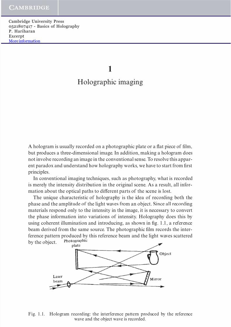
using coherent illumination and introducing, as shown in fig. 1.1, a reference
beam derived from the same source. The photographic film records the inter-ference pattern produced by this reference beam and the light waves scattered
by the object.
1
Fig. 1.1. Hologram recording: the interference pattern produced by the referencewave and the object wave is recorded.
www.cambridge.org© Cambridge University Press
Cambridge University Press0521807417 - Basics of Holography P. HariharanExcerptMore information
8/4/2019 Hariharan Book
http://slidepdf.com/reader/full/hariharan-book 2/10
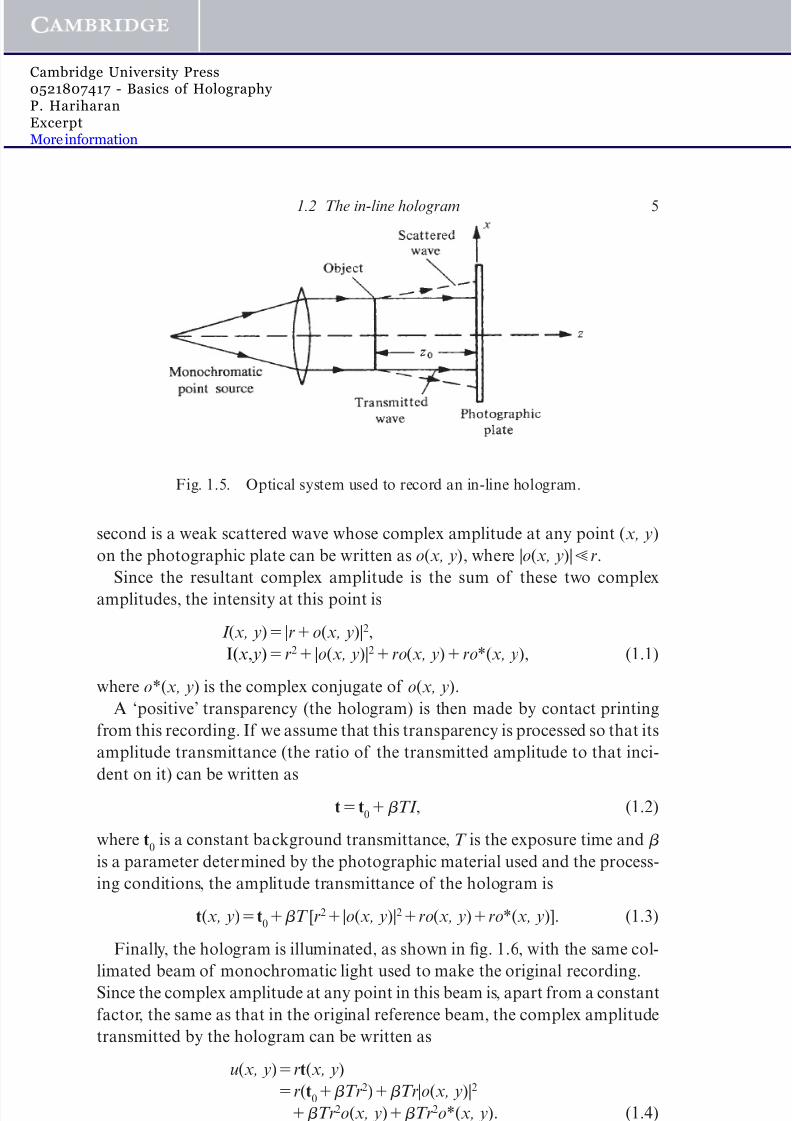
Since the intensity at any point in this interference pattern also depends on
the phase of the object wave, the resulting recording (the hologram) contains
information on the phase as well as the amplitude of the object wave. If the
hologram is illuminated once again with the original reference wave, as shownin fig. 1.2, it reconstructs the original object wave.
An observer looking through the hologram sees a perfect three-dimensional
image. This image exhibits, as shown in figs. 1.3 and 1.4, all the eff ects of per-
spective, and depth of focus when photographed, that characterized the origi-
nal object.
1.1 Early development
In Gabor’s historical demonstration of holographic imaging [Gabor, 1948], atransparency consisting of opaque lines on a clear background was illuminated
with a collimated beam of monochromatic light, and the interference pattern
produced by the directly transmitted beam (the reference wave) and the light
scattered by the lines on the transparency was recorded on a photographic
plate. When the hologram (a positive transparency made from this photo-
graphic negative) was illuminated with the original collimated beam, it pro-
duced two diff racted waves, one reconstructing an image of the object in its
original location, and the other, with the same amplitude but the opposite
phase, forming a second, conjugate image.A major drawback of this technique was the poor quality of the recon-
structed image, because it was degraded by the conjugate image, which was
superimposed on it, as well as by scattered light from the directly transmitted
beam.
The twin-image problem was finally solved when Leith and Upatnieks
2 Holographic imaging
Fig. 1.2. Image reconstruction: light diff racted by the hologram reconstructs theobject wave.
www.cambridge.org© Cambridge University Press
Cambridge University Press0521807417 - Basics of Holography P. HariharanExcerptMore information
8/4/2019 Hariharan Book
http://slidepdf.com/reader/full/hariharan-book 3/10
1.1 Early development 3
Fig. 1.3. Views from diff erent angles of the image reconstructed by a hologram,showing changes in perspective.
www.cambridge.org© Cambridge University Press
Cambridge University Press0521807417 - Basics of Holography P. HariharanExcerptMore information
8/4/2019 Hariharan Book
http://slidepdf.com/reader/full/hariharan-book 4/10
[1962, 1963, 1964] developed the off -axis reference beam technique shown
schematically in figs. 1.1 and 1.2. They used a separate reference wave incident
on the photographic plate at an appreciable angle to the object wave. As a
result, when the hologram was illuminated with the original reference
beam, the two images were separated by large enough angles from the
directly transmitted beam, and from each other, to ensure that they did notoverlap.
The development of the off -axis technique, followed by the invention of the
laser, which provided a powerful source of coherent light, resulted in a surge of
activity in holography that led to several important applications.
1.2 The in-line hologram
We consider the optical system shown in fig. 1.5 in which the object (a trans-
parency containing small opaque details on a clear background) is illuminatedby a collimated beam of monochromatic light along an axis normal to the
photographic plate.
The light incident on the photographic plate then contains two components.
The first is the directly transmitted wave, which is a plane wave whose ampli-
tude and phase do not vary across the photographic plate. Its complex ampli-
tude (see Appendix A) can, therefore, be written as a real constant r. The
4 Holographic imaging
Fig. 1.4. Picture of the reconstructed image taken with the camera lens wide open(f/1.8), showing the eff ect of limited depth of focus.
www.cambridge.org© Cambridge University Press
Cambridge University Press0521807417 - Basics of Holography P. HariharanExcerptMore information
8/4/2019 Hariharan Book
http://slidepdf.com/reader/full/hariharan-book 5/10
second is a weak scattered wave whose complex amplitude at any point (x, y)
on the photographic plate can be written as o(x, y), where |o(x, y)|r.
Since the resultant complex amplitude is the sum of these two complex
amplitudes, the intensity at this point is
I (x, y) |ro(x, y)|2,
I(x, y)r2 |o(x, y)|2ro(x, y)ro*(x, y), (1.1)
where o*(x, y) is the complex conjugate of o(x, y).
A ‘positive’ transparency (the hologram) is then made by contact printing
from this recording. If we assume that this transparency is processed so that its
amplitude transmittance (the ratio of the transmitted amplitude to that inci-
dent on it) can be written as
tt0TI , (1.2)
where t0
is a constant background transmittance, T is the exposure time and
is a parameter determined by the photographic material used and the process-
ing conditions, the amplitude transmittance of the hologram is
t(x, y)t0T [r2 |o(x, y)|2ro(x, y)ro*(x, y)]. (1.3)
Finally, the hologram is illuminated, as shown in fig. 1.6, with the same col-
limated beam of monochromatic light used to make the original recording.
Since the complex amplitude at any point in this beam is, apart from a constant
factor, the same as that in the original reference beam, the complex amplitude
transmitted by the hologram can be written as
u(x, y)rt(x, y)
r(t0Tr2)Tr|o(x, y)|2
Tr2o(x, y)Tr2o*(x, y). (1.4)
1.2 The in-line hologram 5
Fig. 1.5. Optical system used to record an in-line hologram.
www.cambridge.org© Cambridge University Press
Cambridge University Press0521807417 - Basics of Holography P. HariharanExcerptMore information
8/4/2019 Hariharan Book
http://slidepdf.com/reader/full/hariharan-book 6/10
The right-hand side of (1.4) contains four terms. The first of these, r(t0
Tr2), which represents a uniformly attenuated plane wave, corresponds to the
directly transmitted beam.
The second term, Tr |o(x, y)|2, is extremely small, compared to the other
terms, and can be neglected.The third term, Tr2o(x, y), is, except for a constant factor, identical with the
complex amplitude of the scattered wave from the object and reconstructs an
image of the object in its original position. Since this image is formed behind
the hologram, and the reconstructed wave appears to diverge from it, it is a
virtual image.
The fourth term, Tr2o*(x, y), represents a wave similar to the object wave,
but with the opposite curvature. This wave converges to form a real image (the
conjugate image) at the same distance in front of the hologram.
With an in-line hologram, an observer viewing one image sees it superim-posed on the out-of-focus twin image as well as a strong coherent background.
Another drawback is that the object must have a high average transmittance
for the second term on the right-hand side of (1.4) to be negligible. As a result,
it is possible to form images of fine opaque lines on a transparent background,
but not vice versa. Finally, the hologram must be a ‘positive’ transparency. If
the initial recording is used directly, in (1.2) is negative, and the reconstructed
image resembles a photographic negative of the object.
1.3 Off -axis holograms
To understand the formation of an image by an off -axis hologram, we consider
the recording arrangement shown in fig. 1.7, in which (for simplicity) the ref-
erence beam is a collimated beam of uniform intensity, derived from the same
source as that used to illuminate the object.
6 Holographic imaging
Fig. 1.6. Optical system used to reconstruct the image with an in-line hologram,showing the formation of the twin images.
www.cambridge.org© Cambridge University Press
Cambridge University Press0521807417 - Basics of Holography P. HariharanExcerptMore information
8/4/2019 Hariharan Book
http://slidepdf.com/reader/full/hariharan-book 7/10
The complex amplitude at any point (x, y) on the photographic plate due to
the reference beam can then be written (see Appendix A) as
r(x, y)r exp(i2 x), (1.5)
where (sin ), since only the phase of the reference beam varies across thephotographic plate, while that due to the object beam, for which both the
amplitude and phase vary, can be written as
o(x, y)|o(x, y)| exp[i (x, y)]. (1.6)
The resultant intensity is, therefore,
I (x, y) |r(x, y)o(x, y)|2
|r(x, y)|2 |o(x, y)|2
r|o(x, y)| exp[i (x, y)] exp(i2 x)r|o(x, y)| exp[i (x, y)] exp(i2 x)
r2 |o(x, y)|22r|o(x, y)| cos[2 x (x, y)]. (1.7)
The amplitude and phase of the object wave are encoded as amplitude and
phase modulation, respectively, of a set of interference fringes equivalent to a
carrier with a spatial frequency of .
If, as in (1.2), we assume that the amplitude transmittance of the processed
photographic plate is a linear function of the intensity, the resultant amplitude
transmittance of the hologram ist(x, y)t
0 T |o(x, y)|2
Tr |o(x, y)| exp[ i (x, y)] exp( i2 x)
Tr |o(x, y)| exp[i (x, y)] exp(i2 x), (1.8)
where t0t
0Tr2 is a constant background transmittance.
1.3 Off-axis holograms 7
Fig. 1.7. The off -axis hologram: recording.
www.cambridge.org© Cambridge University Press
Cambridge University Press0521807417 - Basics of Holography P. HariharanExcerptMore information
8/4/2019 Hariharan Book
http://slidepdf.com/reader/full/hariharan-book 8/10
When the hologram is illuminated once again with the original reference
beam, as shown in fig. 1.8, the complex amplitude of the transmitted wave can
be written as
u(x, y)r(x, y)t(x, y)
t0r exp(i2 x)Tr|o(x, y)|2 exp(i2 x)
Tr2o(x, y)Tr2o*(x, y) exp(i4 x). (1.9)
The first term on the right-hand side of (1.9) corresponds to the directly trans-
mitted beam, while the second term yields a halo surrounding it, with approx-
imately twice the angular spread of the object. The third term is identical to
the original object wave, except for a constant factor Tr2, and produces a
virtual image of the object in its original position. The fourth term corresponds
to the conjugate image which, in this case, is a real image. If the off set angle of
the reference beam is made large enough, the virtual image can be separated
from the directly transmitted beam and the conjugate image.
In this arrangement, corresponding points on the real and virtual images are
located at equal distances from the hologram, but on opposite sides of it. Since
the depth of the real image is inverted, it is called a pseudoscopic image, as
opposed to the normal, or orthoscopic, virtual image. It should also be noted
that the sign of only aff ects the phase of the reconstructed image, so that a
‘positive’ image is always obtained, even if the hologram recording is a photo-
graphic negative.
1.4 Fourier holograms
An interesting hologram recording configuration is one in which the
complex amplitudes of the waves that interfere at the hologram are the Fourier
8 Holographic imaging
Fig. 1.8. The off -axis hologram: image reconstruction.
www.cambridge.org© Cambridge University Press
Cambridge University Press0521807417 - Basics of Holography P. HariharanExcerptMore information
8/4/2019 Hariharan Book
http://slidepdf.com/reader/full/hariharan-book 9/10
transforms (see Appendix B) of the complex amplitudes of the original object
and reference waves. Normally, this implies an object of limited thickness, such
as a transparency.
To record a Fourier hologram, the object transparency is placed in the front
focal plane of a lens, as shown in fig. 1.9, and illuminated with a collimatedbeam of monochromatic light. The reference beam is derived from a point
source also located in the front focal plane of the lens. The hologram is
recorded on a photographic plate placed in the back focal plane of the lens
[Vander Lugt, 1964].
If the complex amplitude of the wave leaving the object plane is o(x, y), its
complex amplitude at the photographic plate located in the back focal plane of
the lens is
O( , )F {o(x, y)}. (1.10)
The reference beam is derived from a point source also located in the front
focal plane of the lens. If (xb, y) is the complex amplitude of the wave
leaving this point source, the complex amplitude of the reference wave at the
photographic plate can be written as
R( , )exp( i2 b). (1.11)
The intensity in the interference pattern produced by these two waves is,
therefore,
I ( , )1|O( , )|2O( , ) exp(i2 b)
O*( , ) exp( i2 b). (1.12)
To reconstruct the image, the processed hologram is replaced in the front
focal plane of the lens, as shown in fig. 1.10, and illuminated with a collimated
beam of monochromatic light.
1.4 Fourier holograms 9
Fig. 1.9. Optical system used to record a Fourier hologram.
www.cambridge.org© Cambridge University Press
Cambridge University Press0521807417 - Basics of Holography P. HariharanExcerptMore information
8/4/2019 Hariharan Book
http://slidepdf.com/reader/full/hariharan-book 10/10
If the incident wave has unit amplitude, and the amplitude transmittance of
the processed hologram is a linear function of the intensity, the complex ampli-
tude of the transmitted wave is
U ( , )t0TI ( , ). (1.13)
The complex amplitude in the back focal plane of the lens is then the Fourier
transform of U ( , ). We have
u(x, y)F {U ( , )}
(t0T ) (x, y)To(x, y) ★ o(x, y)
To(xb, y)To* (xb, y). (1.14)
As shown in fig. 1.10, the wave corresponding to the first term on the right-
hand side of (1.14) comes to a focus on the axis, while that corresponding tothe second term forms a halo around it. The third term produces an image of
the original object, shifted downwards by a distance b, while the fourth term
gives rise to a conjugate image, rotated by 180° and shifted upwards by the
same distance b.
Fourier holograms have the useful property that the reconstructed image does
not move when the hologram is translated in its own plane. This is because a shift
of a function in the spatial domain only results in its Fourier transform being
multiplied by a phase factor which has no eff ect on the intensity distribution.
1.5 Lensless Fourier holograms
A hologram with the same properties as a Fourier hologram can be produced,
without a lens, with the arrangement shown in fig. 1.11 in which the object is
illuminated with a plane wave, and the reference wave comes from a point
source in the plane of the object [Stroke, 1965].
10 Holographic imaging
Fig. 1.10. Image reconstruction by a Fourier hologram.
www cambridge org© Cambridge University Press
Cambridge University Press0521807417 - Basics of Holography P. HariharanExcerptMore information