FOR FURTHER INFORMATION CONTACT: Harvey-3 Final Well report Department of Mines and Petroleum South West Hub Carbon Capture and Storage Project Peter Nims and Murray Pollock DDH1 Drilling Pty Ltd December 2015 DDH1 Drilling 123 Stirling Hwy, North Fremantle, WA, 6159 P: +61 (0)8 9435 1700 F: +61 (0)8 9435 1799
7) Aquifer Sampling 8 8) Completion 9 9) Mud Program 9 10) Bit Record 11 11) Community Engagement 12 12) Discussion of Outcomes 13 13) References 15
LIST OF TABLES TABLE NO. TITLE PAGE NO. 1 Harvey-3, Well Specifications, 2 2 Harvey-3, Site Equipment and Rig Personnel 4 3 Harvey-3, Summary Bit Record 10
LIST OF FIGURES FIGURE NO. TITLE PAGE NO 1 Harvey-3 Well Design and Timeline (Planned vs Actual) 3 2 Harvey-3 Intermediate Casing Leak Off Test Results 6
APPENDICES APPENDIX 1: Harvey-3 Daily Drilling Reports APPENDIX 2: Australian Mud Company Drilling Fluid Summary for Harvey-3
DDH1 Harvey-3 Final Well report
Page 1
HARVEY-3 FINAL WELL REPORT
1. Introduction
In late 2014, DDH1 Drilling Pty Ltd (DDH1), in conjunction with Drilling Contractors Australia (DCA) and Rockwater Pty Ltd (Rockwater), were awarded a contract by the WA Department of Mines (DMP) to drill and geologically log three wells in the Harvey area of the Perth Basin, approximately 150km south of Perth. The three vertical wells, Harvey-2, -3, and -4, were to be drilled as a part of ongoing investigations in the South West Hub Carbon Capture and Storage (CCS) Project – a joint endeavour by the Federal and WA State Governments, various research institutions and private industry.
DDH1 was appointed as lead contractor with overall site responsibility together with direct responsibility for drilling wells Harvey-2 and Harvey-3, both of which were to be continuously cored to estimated total depths of 1350 and 1550m respectively. DDH1’s brief also included mud-rotary drilling an additional 52m monitoring bore adjacent to the Harvey-4 site for Geophone installation.
DCA was subcontracted to drill well Harvey-4 to an estimated total depth of 1800m. Harvey-4 was to be drilled open hole with limited core runs in zones of specific interest.
Rockwater was subcontracted to provide on-site hydro-geological logging services and supervision for all three holes and DDH1 engaged the Australian Mud Company to provide mud engineering, mud products and services for the entire program.
Ongoing field investigations and earlier drilling (Harvey-1, Millar and Reeve, 2014) had determined that the strata were highly unlikely to be over-pressured or to yield hydrocarbon flows. However, as a precautionary measure, the drilling programs were undertaken using appropriate well control and mud systems. The completion of Harvey-2 and DCA’s ongoing experiences in Harvey-4 also served to highlight some local drilling challenges with respect to rapid down-hole lithological variations in competency, stability, clay content and abrasiveness (Russell and Pollock, November 2015).
Harvey-3 commenced immediately after the completion of Harvey-2 and experience gained in the latter (continuously cored in 83mm diameter PQ 3 and 61.1mm diameter HQ3 core from 204m to 1350m), influenced drill bit selection and drilling fluid engineering for Harvey-3 which was planned to be completed in larger diameter core (102mm SQ3) to 1550m.
This report summarises operational and technical aspects of the drilling program undertaken by DDH1 to successfully complete Harvey-3. In particular, the report captures all drilling intervals and documents the drilling practise and mud engineering responses to the various issues encountered whilst drilling the well.
DDH1 Harvey-3 Final Well report
Page 2
2. Specifications and Well Design Well design for Harvey-3 was undertaken by DDH1 in consultation with DMP staff taking account of:
• the project’s technical objectives and budgetary constraints, • prior drilling experience at Harvey-1 (including a review of all drill reports, geophysical logs and
inspection of core), • recent experiences at Harvey-2 and ongoing experiences at Harvey-4, • environmental and safety considerations, • original hole specifications (DMP Tender 120214 and subsequent revisions).
Hole specifications are shown in Table 1 and the well plan is shown diagrammatically in Figure 1.
Table 1: Harvey-3 Well Specifications
Specification Original (DMP Tender & revisions) Final (on completion) Dip: -90o -90o Azimuth: 000o 000o Total Depth: 1,400 – 1,500m (subject to change) 1550.2m Minimum core size PQ SQ to 1462.3m, HQ to 1550.2m Intermediate casing 250m 586m Hole Orientation Not required. Not undertaken Wireline Logging To EOH To 1550m
Casing 4 ½” carbon steel to EOH 4 ½” carbon steel to 1150m and 4 ½” high chrome to 1462m grouted to 7”
Completion TBA Plugged at base of casing, capped at surface
3. Personnel and Equipment
DDH1’s equipment choices for Harvey-3 were similar to those for Harvey-2 (Russell and Pollock, November 2015) with the exception that the decision to maximise core recovery /preservation and geotechnical information by drilling the second hole in larger, 102mm-diameter SQ3 core necessitated changing the rig’s downhole wireline drilling system. The standard Q system used in Harvey-2 (with maximum PQ-size core capability) was replaced by an Atlas Copco SQ wireline system for Harvey-3. With its low-profile downhole components, the recently developed Atlas Copco system enables a large-diameter (102mm) SQ core (only slightly smaller than conventional oil-rig sized core) to be cut within a “slim hole” using a smaller, more cost-effective mineral rig. Boart-Longyear 5.5’’ PWT casing was selected as drill-pipe for the SQ drilling.
Prior to the drilling of Harvey-3, industry-wide utilisation of the Atlas Copco SQ system had been limited to relatively shallow site work. However detailed investigations suggested that the capabilities of the system and DDH1’s pull-back-enhanced Rig 16 were well-matched to achieve the technical challenge of SQ coring Harvey-3 to 1550m – potentially the world’s deepest SQ core hole.
DDH1 Harvey-3 Final Well report
Page 3
The Atlas Copco SQ components were supplied in three meter lengths and DDH1 engineered a core barrel and inner-tube joiners to form a 9.6m wireline core barrel. PWT casing was selected as drill-pipe for the SQ drilling.
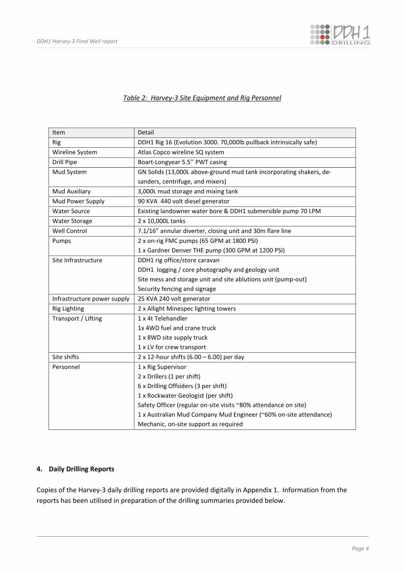
Details of other on-site equipment and personnel utilised in drilling Harvey-3 are shown in Table 2.
Figure 1: Harvey-3 Well Design and Timeline (Planned vs Actual)
0
200
400
600
800
1000
1200
1400
1600
0 20 40 60 80 100 120
Depth (m)
Time (Days)
Harvey-3 Planned
Harvey-3 Actual
aaa
bbb
Drill SQ core 588 - 1463m
Drill (8-1/2') 74 - 588m
Cement hole back to intemediate casing from 744m & redrill
Run & cement (7') casing
Drill 0 - 50m
Planned casing 250m
Drill SQ core 250 - 1550m
Drill HQ core 1463 - 1550m
Run & cement 4-1/2' casing
Abandonment
DDH1 Harvey-3 Final Well report
Page 4
Table 2: Harvey-3 Site Equipment and Rig Personnel
Item Detail Rig DDH1 Rig 16 (Evolution 3000. 70,000lb pullback intrinsically safe) Wireline System Atlas Copco wireline SQ system Drill Pipe Boart-Longyear 5.5’’ PWT casing Mud System GN Solids (13,000L above-ground mud tank incorporating shakers, de-
sanders, centrifuge, and mixers) Mud Auxiliary 3,000L mud storage and mixing tank Mud Power Supply 90 KVA 440 volt diesel generator Water Source Existing landowner water bore & DDH1 submersible pump 70 LPM Water Storage 2 x 10,000L tanks Well Control 7.1/16” annular diverter, closing unit and 30m flare line Pumps 2 x on-rig FMC pumps (65 GPM at 1800 PSI)
1 x Gardner Denver THE pump (300 GPM at 1200 PSI) Site Infrastructure DDH1 rig office/store caravan
DDH1 logging / core photography and geology unit Site mess and storage unit and site ablutions unit (pump-out) Security fencing and signage
Infrastructure power supply 25 KVA 240 volt generator Rig Lighting 2 x Allight Minespec lighting towers Transport / Lifting 1 x 4t Telehandler
1x 4WD fuel and crane truck 1 x 8WD site supply truck 1 x LV for crew transport
Site shifts 2 x 12-hour shifts (6.00 – 6.00) per day Personnel 1 x Rig Supervisor
2 x Drillers (1 per shift) 6 x Drilling Offsiders (3 per shift) 1 x Rockwater Geologist (per shift) Safety Officer (regular on-site visits ~80% attendance on site) 1 x Australian Mud Company Mud Engineer (~60% on-site attendance) Mechanic, on-site support as required
4. Daily Drilling Reports
Copies of the Harvey-3 daily drilling reports are provided digitally in Appendix 1. Information from the reports has been utilised in preparation of the drilling summaries provided below.
DDH1 Harvey-3 Final Well report
Page 5
5. Summary of Pre-Spud and Rig-Up Procedures (March 5 – 6, 2015) Drill pad preparation and access works for Harvey-3 were completed by a local landholder during February 2015 under the supervision of KD1 Pty Ltd (KD1). Prior to commencing rig-up operations DDH1 staff refurbished an existing water bore located approximately 400m from the drill collar and installed a submersible pump to enable a local water supply for the drilling operations.
Rig 16 moved from Harvey-2 to the Harvey-3 site on March 5 and, after a review of safe-work procedures, rig-up operations commenced. Rig preparation was completed by the end of day-shift, March 6.
Harvey-3 operations commenced at the beginning of night-shift, March 6, 2015. The conductor hole was drilled with a 16” blade bit and bentonite base mud to a depth of 6.5m. Steel 12 ¼” ID collar casing was then installed and grouted back to surface using 600L of 15.3ppg cement.
Surface Casing (Tricone, 12⅛” hole, 6.5 - 74m):
The hole was progressed from 6.5m to 74m using a 8 ½’’ tricone bit and was subsequently reamed out to a 12 ⅛” diameter hole. A wiper run was then completed to 74m in preparation for running surface casing.
During casing operations, 9 ⅝” buttress casing with float shoe and centralizers was run to 72m and no backfill was encountered. Cementing operations utilised 2500L @ 14.5ppg cement slurry pumped with a displacement plug until cement slurry returns were observed at the surface.
Whilst waiting for the cement to cure, it was noted that the cement slumped and a 115L top-up mix ensured full cement coverage to surface. There were no groundwater flows at Harvey-3 as encountered at Harvey-2.
Based on experience at Harvey-2, the originally-specified 250m intermediate casing depth for Harvey-3 was extended to approximately 586m – at which depth it was expected that ground conditions would be sufficiently sound to enable secure casing. The 8 ½” hole was rotary drilled with a KCl/polymer mud mix and reached 588m on March 18 2015.
During the wiper run, minimal backfill was encountered. However, to ensure a perfectly clean hole, a second wiper trip was conducted. A 585.8m, 7” BTC casing string was then run to depth and 10,000L of GP cement (at 14ppg) was pumped and displaced with positive returns observed at surface. The displacement plug was bumped to 600psi and held for 30 minutes and a subsequent 180L cement top-up was required to completely fill the annulus to the surface.
The BOP was installed and BOP function tests and pressure tests were conducted before drilling out the 7” shoe and completing a successful leak off test (LOT). The results of the LOT are shown in Figure 2.
DDH1 Harvey-3 Final Well report
Page 6
Figure 2: Harvey-3, Intermediate Casing Leak-Off Test Results
SQ3 Coring (588m - 744 m):
The formation encountered during the initial 120m of SQ3 core drilling was relatively soft and friable and occasional small core losses were incurred. In order to improve the hole integrity for subsequent coring activity, it was decided to drill-on to firmer ground and then grout the hole back to the casing string and redrill the cemented section.
By 744m it was considered that the ground was consistently consolidated and the hole was grouted from this depth back into the 7’’ casing. After allowing the grout to set a 5⅞” tricone was run to drill-out the cemented section. At 668m during the re-drill, the tricone bit ran off the cemented hole. At this point SQ coring was recommenced (within the deviated hole) and full-core recovery back to 744m was achieved. This section of the hole remained stable throughout subsequent drilling activities.
SQ3 Coring (744m - 900m):
During the interval from 744 to 900m, core recovery was maintained at almost 100% with only occasional undersized core sections. However, drilling progress was slow due to difficulties penetrating the rapidly changing competency contrasts in downhole formations (variably interbedded siltstone, mudstone and clay beds with hard and abrasive pyritic sandstone beds).
Informed by DDH1’s prior experiences at Harvey-2 and by DCA’s continuing rotary drilling operations at Harvey-4, the Harvey-3 mud weight throughout this interval was maintained at 10.2ppg and 42-50 second viscosity using a KCL/Pac base mix.
0
100
200
300
400
500
600
700
0 20 40 60 80 100 120 140 160
Pres
sure
(psi
)
Volume (Litres)
DDH1 Harvey-3 Final Well report
Page 7
SQ3 Coring (900m - 1337m):
Downhole lithologies encountered in the interval 900m to 1337m were harder than up-hole units and included silicified fine grained to pebbly sandstone with garnet-rich cross laminations. The SQ drill bit was changed at 884m from a surface set to an impregnated diamond bit which was considered more suitable for the harder ground. Despite this bit change, penetration remained very slow and at 934m the bit was swapped out again for a Carbonaro surface-set design. Although the Carbonaro bit had performed relatively well in Harvey-2 (Russell and Pollock, 2015) this performance was not able to be replicated in Harvey-3 and penetration rates continued to be low.
Throughout this interval, Harvey-3 experienced increasing fluid losses ranging between 1500 and 7000L per shift with the most significant deficits noted at 946m, 1053m and 1083m. Although the losses were partly controlled by continuous addition of lost circulation material, the high LCM concentrations were affecting pump efficiency and causing problems with the minimal clearances in the core drilling barrel.
SQ3 Coring (1337m – 1462m)
At 1337m, in attempt to further reduce ongoing fluid losses, the mud weight was gradually reduced from 10ppg. Whilst this strategy was initially successful, on contact with a sandstone formation at 1418m, fluid losses again increased. These were controlled by a further gradual reduction in mud weight to 9.2ppg by 1430m and losses were minimised. However, high circulation pressures were noted when reaming a new core bit to bottom at 1424m. Subsequent progress was very slow until the drill pipe finally became stuck at 1462m.
SQ Coring, Stuck drill pipe at 1462m:
Despite the drill pipe being stuck 6m off-bottom, full-circulation was nonetheless able to be maintained and the cause of the problem was assessed as differential sticking of the rod line. Several pills were pumped without effect over the next three days and it was only after the mud weight was lowered to 8.9ppg that the drill pipe was able to be worked free utilising the rig in dual-pull mode at 90,000 lbs of pullback.
Wireline Logging at 1462m:
In order to avoid the risk of irretrievably stuck drill pipe preventing successful open-hole wire-line logging, it was decided to run the electrical logs while the hole was clear of pipe before recommencing core drilling. After several wiper trips with 10ppg mud to condition the hole, it became obvious that the low SG remedial fluid used to overcome differential sticking had severely affected drill hole stability.
On May 31, Halliburton commenced wireline logging but the logging tool was unable to progress beyond 927m and was recovered to surface. Numerous reaming runs with a range of BHA were subsequently undertaken in attempt to recondition the hole. However, on June 8 when wireline logging recommenced the tool again stopped at 970m.
DDH1 Harvey-3 Final Well report
Page 8
Completion Casing at 1462m
With deteriorating hole conditions causing a high risk of jamming the logging tool, it was decided to run 4.5’’ completion casing to 1462m and drill the remaining portion of the hole in HQ core to the planned total depth of 1550m. Although the recovered core volume would be reduced relative to SQ, the 97mm diameter hole cut by the HQ coring system would still be sufficiently large to enable wireline logging tools to pass.
To reduce the risks of running casing in the deteriorating hole, 300m of high chrome casing with upset tool joints was re-machined to be externally flush. In addition, 33 lengths of 9m casing (originally designed to be run in by winch) were shortened to 6m to allow the casing to be drilled to depth using the rig top-drive.
Multiple unsuccessful attempts were made to drill the casing to depth using a range of standard bottom-hole assemblies. DDH1 subsequently requisitioned a custom-built float shoe incorporating full-hole tungsten blades and this assembly was able to be drilled to 1461m. In order to cement the completion casing back into the existing 7” casing, a total of 14,500L of 13.6ppg cement slurry needed to be pumped. This volume represented a 45% overcall on theoretical hole volume and can be considered indicative of the overall poor ground conditions.
The stuck drill pipe, drill hole logging, re-machining casing and running casing represented a significant loss of time as 24 days elapsed between production shifts.
HQ Coring (1462 – 1550m, TD)
HQ coring commenced with drilling out the full-hole tungsten faced float shoe without difficulty. A leak off test was conducted at 1467m to the pump relief pressure of 1725psi and no leak off was observed.
Previous instances of stuck drill pipe in Harvey-2 and Harvey-3 had typically occurred after pulling inner-tubes when, under normal drilling practise, the drill pipe remains stationary in the hole while the overshot is lowered and the inner-tube is recovered. Depending on hole depth, the rods can be immobile for as long as 1.5 hours during this process. In order to circumvent the potential for similar incidents in the final HQ section of Harvey-3, the decision was made to pull the core barrel back into the completion casing (i.e. above 1462m) in order to retrieve each inner-tube of HQ core. This avoided any instances of potentially risky stationary drill pipe in the uncased portion of the hole. HQ coring continued without incident and Harvey-3 reached the planned TD of 1550.2 on June 24, 2015.
Wireline Logging (1550m)
After the drill pipe was pulled from hole, wireline logging to full depth was successfully completed by Halliburton over a 30-hour period.
7) Aquifer Sampling
After geophysical logging was completed, aquifer sampling specifically targeting the Wonnerup Member commenced. Under the direction of Rockwater and DMPWA staff, DDH1 lowered an open HRQ drill string to 2m above TD (1548m) and the 10ppg drilling mud was displaced from hole with clean, freshgroundwater,
DDH1 Harvey-3 Final Well report
Page 9
from the locally refurbished water supply bore. A submersible pump was lowered to 70m inside the HRQ drill pipe and the hole was pumped at 70L/min for 14 hours.
Representative groundwater samples were collected to measure salinity and temperature and the static water table head was measured. A full report on the aquifer sampling techniques and results has been submitted independently to DMPWA by Rockwater (Rockwater, August 2015).
8) Completion
Three Van Ruth CWBP packers were pumped down the HRQ drill pipe with the aim of lodging them at the base of the completion casing. However, due to the fine sand content in the groundwater the packers locked prematurely inside the drill pipe. The pipe was subsequently pulled and cleared of the packers before re-running to 1450m and displacing the groundwater with clean 10ppg mud. The packers were pumped a second time but once again jammed in the drill string. The string was pulled and cleared of packers again and re-lowered to 1450m with the packers pre-set from surface into the first drill pipe.
Once the leading drill pipe was lowered into the final casing length, the three Van Ruth packers were pumped out of the drill pipe and locked into the deepest casing joint. Stored Wonnerup Member fluid was then used to displace the drilling mud from the hole and the HQ drill pipe was pulled from the hole in 6m lengths. Site head-works were installed and the casing and plugs pressure tested to 1,000psi without pressure loss.
Once Harvey-3 was securely capped, rig-down procedures were completed and the rig was demobilised to drill a monitoring bore at the Harvey-4 site.
9) Bit Record
A summary of bit usage throughout the Harvey-3 hole is provided in Table 3. Analysis of the data and comparison of the bit records for Harvey-3 relative to Harvey-2 (Russell and Pollock, 2015) shows that:
• Somewhat surprisingly, the bit designs that performed best in Harvey-2 did not provide the same performance differential in Harvey-3. This could be due to formation differences between the two sites or, as bit design seemed almost irrelevant to rate of penetration (ROP), perhaps mud weight or viscosity was an overriding influence on penetration rates in Harvey-3.
• In attempting to determine the optimal bits for drilling progress in Harvey-3, bit changes were more frequent than ideal.
• Fourteen core bits were used in Harvey-3 compared to 23 core bits in Harvey-2 for a similar length of core drilling. Not all bits were completely worn at the end of their run as several bit changes were made in a bid to determine the optimal design to increase ROP.
DDH1 Harvey-3 Final Well report
Page 10
Table 3: Harvey-3, Summary Bit Record
Date Depth Depth Interval Size Type Style Serial No. Manufacturer Formation
AMC was contracted to supply product and mud engineering services on as needs basis for the entire Harvey drilling program including:-
• Pre-drill test work on historic samples from drill hole Harvey-1 with a view to designing and costing the most appropriate drilling fluids for the current program,
• On-going monitoring and technical support during drilling activities at Harvey-2 -3 and 4,
• A review of the effectiveness of the various mud programs with the aim of informing future drilling for the Harvey Sequestration Project.
Mud engineering services were supplied by AMC’s Mineral Division at no additional charge beyond the product costs. The company’s engineers were on site for extended periods and followed daily progress while absent. In practise, the engineering time commitment greatly exceeded original estimates due to extended hole completions and the intense level of oversight required to monitor the drilling fluids and formation responses in the fragile drilling environment presented by Perth Basin sediments in the Harvey area.
AMC’s Harvey-3 Drilling Fluid Summary Report is included herein as Appendix 2 and summary comments drawn from it and from DDH1’s on-site experience are listed below:
• Experience gained from both Harvey-2 and -4 indicated that high mud weights assisted hole stability. In Harvey-3, mud weight throughout the critical coring section was maintained between 9.8 – 10.2ppg until 1337m, after which the mud weight was gradually reduced to 9.2ppg (by 1430m) to control mud losses. After the SQ drill pipe became differentially stuck at 1462m, the mud weight was reduced to 8.5 lb/gal and once the pipe was freed, the mud weight was lifted to 10ppg until completion at 1550m.
• The KCl/PAC R fluid was successful and allowed SG to be controlled without adding contained solids. In planning future wells to be drilled in a similar manner at Harvey, the use of high SG fluids and other LCM options could be considered.
• The initial KCl mix was run at 110,000 to 127,000ppm chlorides with a mud weight SG of 1.1 (9.8-10.2 lb/gal). Throughout the hole, chloride concentrations were kept between 110,000 to 127,000ppm, with variations mostly due to individual testing techniques and the timing of sample collection.
• In planning similar wells in the Harvey area, a continuous site presence of an experienced oilfield
mud engineer is recommended.
DDH1 Harvey-3 Final Well report
Page 12
Actual drilling fluid costs for Harvey-3 were in excess of budget estimates due to:
• the overall extended drilling timetable,
• the change from PQ to larger diameter SQ coring,
• cementing back and re-drilling poor ground from 588-744m as well as dumping a proportion of the mud containing the drilled cement cuttings,
• greater-than-anticipated volumes of downhole mud losses and the subsequent product required for make-up fluid.
• greater-than-anticipated quantities of LCM material introduced to stem losses,
• the need to use mud pills in attempting to free stuck drill pipe,
• the events surrounding displacing the hole volume with low SG fluid and subsequent high product usage for the re-medial hole conditioning program were not anticipated.
Additional information from AMC about the Harvey-3mud engineering program is included in Appendix 2. 11) Community Engagement
In consultation with clients, DDH1 seeks to positively engage with community stakeholders on all drilling projects. Working collaboratively with DMP and KD1 staff throughout the Harvey drilling program, DDH1 sought to:-
• establish and maintain good relations with local land-owners,
• locally source accommodation and messing (rather than bringing the company’s camp onto site),
• purchase of non-drilling consumables from local suppliers,
• Engage local tradespeople and services when necessary (e.g. electrical, mechanical, engineering, cementing, some transport, etc.),
• facilitate safe rig site access for client-hosted Open Days and Site Visits,
• minimise traffic, dust, noise, stock disturbance, etc., both at the rig site and on local roads,
• address any concerns promptly and respectfully,
• maintain a clean, tidy, secure and safe work site,
DDH1 Harvey-3 Final Well report
Page 13
• minimise environmental disturbance at all times. Whilst drilling Harvey-2 and -3, many visitors came to site including local community representatives and various academics, as well as CSIRO and DMP staff. Visitors were hosted by the DMP with safety input from DDH1 and engaged positively with the on-site drilling and geological staff. A highlight of Harvey-3 was a Staff and Family Day hosted by the DMP. The day was well-attended by families of DDH1 field and office staff who rarely have an opportunity to visit a working drill rig. Whilst the location of the rigs became well known throughout the area, there were no instances of unauthorised access to the drill sites and no visible opposition to the drilling activity. In general, the Harvey town-site and rural community were very welcoming and co-operative towards the drilling crews.
12) Discussion of Outcomes
To date, most deep drill holes in the variably consolidated sedimentary rocks of the Perth Basin have been completed for oil and gas targets using large-scale oil-field rigs and rotary mud drilling techniques with only limited core runs in zones of specific interest. The first hole in the South West Hub CCS Project, Harvey-1, was drilled in this manner (Millar and Reeve, 2014).
The requirement for continuous, large-diameter core to depth in Harvey-2 & -3 as an integral part of ongoing research in the South West Hub CCS, provided an innovative opportunity for the application of continuous wireline core drilling techniques using a heavy-duty slim-hole rig of the type more conventionally used in the mineral exploration sector. DDH1’s Rig 16, an Evolution 3000 with extended pull back capacity and the chosen mud system were well suited to this task.
Impressions gained from pre-program inspection of the restricted cored intervals from Harvey-1 formed an integral part of the Harvey-2 and -3 well designs and drilling plans. However, in practise, lithologies encountered in the Wonnerup and Yalgorup Members in the latter two holes were harder to penetrate than expected from inspection of Harvey -1 core. Furthermore, the sandstone formations encountered in Harvey-3 appeared to be harder than similar units in Harvey-2.
It is not known whether these differences are related to inherent variability in the sedimentary pile - possibly controlled by proximity to the Darling Fault - or whether they are related to increased secondary silicification – perhaps due to increased faulting /fracturing the vicinity of Harvey-3. Locally intense ferruginisation effects were also noted throughout much of the core and may have contributed to variabilities in down-hole competency.
Other formation features (essentially confined to the Yalgorup and Wonnerup Members) that presented some drilling issues included:
DDH1 Harvey-3 Final Well report
Page 14
• at the local scale, porous and permeable very coarse to gritty sandstone beds (requiring sealing with lost circulation materials (LCM)) in contact with significantly finer-grained horizons (with potential for swelling clays),
• more friable horizons with potential for wash-out and caving,
• at the larger scale, the transition from the Yalgorup to Wonnerup Members (with potential for differential sticking largely related to differential clay components).
Formation variability combined with very hard and abrasive characteristics meant that, relative to the original Harvey-3 hole plan, the rate of progress (ROP) was (unavoidably) slower than anticipated and that more-than-expected bit changes and rod-line trip-outs were required. While several very different drill bits designs were trialled, all bits were slow to penetrate. Extended drilling times and increased down-hole mechanical activity result in lengthened exposure times to drilling fluids and annular pressures which, for time-sensitive formations, can lead to significant deterioration and failure.
The overall penetration rate in Harvey-3 was also slower than in Harvey-2. Whilst this is partly due to the extra time required to cut the larger diameter SQ core in Harvey-3, the core size differential alone is insufficient to explain the ROP variation. Considerably slower than-expected penetration rates were also noted in the rotary-mud drilled Harvey-4 and it seems possible that local formation effects may be a significant ROP-influencing factor.
In Harvey-3 critical attention to adequately inhibited and correctly weighted drilling mud was largely successful in stabilising the hole. However, after the delays incurred with the stuck rod line at 1462m (close to the critical Wonnerup Member - Yalgorup Member transition) it was obvious that the entire cored section was breaking down and very prone to differential sticking.
Features inherent in wireline coring equipment (e.g., small annulus and a high wall contact area) increase differential sticking potential and once a wireline rod string becomes stuck it is more difficult to free than a conventional drill string. Furthermore, the thin-walled internally and externally flush nature of wireline drill pipe joints are more prone to failure whilst being worked than a similar-sized rotary drill string with up-set tool joints. However, despite the severity of the sticking event at 1462m in Harvey-3 (i.e. occurring over several days and requiring application of 90,000lb pullback in dual rig/winch mode before retrieval) no rod line failures occurred. The Boart-Longyear 5.5’’ PWT casing chosen for use as drill-pipe with the SQ system performed well under these onerous conditions.
Variations in annular pressure are also an inherent feature of the wireline core-drilling cycle and may have been a factor in worked loss zones causing formation breakdown. These sorts of variations would not occur in a rotary drilled hole where high annular clearances and consistent annular pressures can be maintained. It is unlikely that a rotary-drilled well through the same formations as Harvey-3 would have experienced similar problems to the wireline coring due to: overall increased drilling speed; greater annular clearance; relatively constant annular pressure; constantly rotating drill-pipe; lack of downhole swabbing (whilst retrieving wireline cores).
DDH1 Harvey-3 Final Well report
Page 15
A review of rig and equipment performance at Harvey-3 indicates that the enhanced pullback capacity of Rig 16 with dual rig/winch mode was a significant factor in successful completion (both to handle the heavy SQ rod line and to retrieve the stuck rod line). The Atlas Copco SQ barrel proved reliable with minimal stuck or miss-latched inner-tubes. In combination with the Boart-Longyear 5.5’’ PWT rod line, it also performed well under the difficult drilling conditions referred to above. The mud system performed adequately - however, given the critical nature of drilling fluid control in completion of Harvey wells, a larger capacity system could be considered for future drilling programs. The deployment of an experienced full-time mud engineer on future programs could also be considered. At a depth of 1463m, the SQ-cored section of Harvey-3 is one of the world’s deepest SQ core holes to date. With the enhanced geotechnical information afforded by continuous large-diameter core, it probably also represents one of the foremost lithological data sets recorded in the global search for potential carbon sequestration sites.
Whilst it was disappointing that the entire Harvey-3 hole could not be completed in SQ3 core, the inherent flexibility of the wireline coring system and the ability to reduce to HQ still enabled complete core coverage to TD at 1550 m. Destructive rotary-mud drilling techniques could obviously not have achieved this outcome.
Notwithstanding the challenges encountered in drilling both Harvey-2 and Harvey-3, successful completion of the wells to target depth endorses slimhole wireline continuous coring as a viable drilling technique in the young and variably-consolidated sediments of the Perth Basin when the enhanced geological and geotechnical information that only core can provide is required.
13) References
Millar, A S and Reeve, J, 2014. GSWA Harvey 1 Well completion and preliminary interpretation report, southern Perth Basin, GSWA Record 2014/12.
Rockwater, August 2015. Harvey 3 Lesueur Formation Fluid Sampling. Report for the Department of Mines and Petroleum, unpublished. Rockwater report No. 437-0/15/01.
Russell, R and Iley, T, December 2015. Harvey-4 Final Well report, South West Hub Carbon Capture and Storage Project. Report to Department of Mines and Petroleum Western Australia, unpublished.
Russell R and Pollock M, November 2015. Harvey-2 Final Well report, South West Hub Carbon Capture and Storage Project. Report to Department of Mines and Petroleum Western Australia, unpublished.
DDH1 Harvey-3 Final Well report
APPENDICES
APPENDIX 1: Harvey-3 DDH1 Daily Drilling Reports (provided as digital copy only)
DDH1 Harvey-3 Final Well report
APPENDICES
APPENDIX 2: Australian Mud Company Harvey-3 Drilling Fluid Summary Report
Harvey-3 Final Well report Appendix 2: Australian Mud Company, Harvey-3 Drilling Fluid Summary Report
Harvey-3
Drilling Fluid Summary Report
AMC Minerals Western Australia November 2015
216 Balcatta Road, Balcatta WA, Australia 6021 PO Box 1141, Osborne Park WA, Australia 6916 Tel: +61 (0) 8 9445 4000 Fax: +61 (0) 8 9445 4040 [email protected] www.amcmud.com ABN 56 009 283 416
Harvey-3 Final Well report Appendix 2: Australian Mud Company, Harvey-3 Drilling Fluid Summary Report
TABLE OF CONTENTS Item Page No
1. Introduction 1 2. General Design Principles for the Drilling Fluids Program 1 3. Harvey-1, Data Review and Geotechnical Testwork 2 4. “Make-Up” Water Analysis 3 5. Drilling Fluid Proposal 3 6. Mud Program Operations 4 6.1 Pre-Collar Section (0-588m) 4 6.2 Cored Section (588-1550m) 4 7. Materials Consumption and Cost Analysis of the Harvey-3 Drilling Fluid Program 6 8. Conclusions and Recommendations 8 9. References 8
LIST OF TABLES Table Page No
1 Sample intervals and fluid combinations selected for Phase 1 and Phase 2 test work on historic Harvey-1 cuttings and core 2
2 Fluid additions whilst coring 5 3 Equivalent circulation densities (ECD) 5 4 Initial non-weighted fluid volumes 6 5 Fluid properties prior to and after stuck pipes 7 6 Harvey-3, Programmed vs actual materials consumption and costs 7 7 Harvey-3, Summary of cost variance for the original (un-weighted) and 8
revised (weighted) mud programs
ATTACHMENTS Pre-Drill Test Work (Historic Samples from GSWA Harvey-1):
Attachment A: Immersion Testing Program 1, September, 2014 Attachment B: Immersion Testing Program 2, November, 2014
Harvey-3 Final Well report Appendix 2: Australian Mud Company, Harvey-3 Drilling Fluid Summary Report
Appendix 2 Page 1
1. Introduction
In September, 2014, the Australian Mud Company (AMC) was engaged by DDH1 Drilling to provide technical support and ongoing mud supplies for deep drill holes Harvey-2, -3 and -4 in the South West Hub Carbon Capture and Storage (CCS) Project. AMC’s brief was to provide:-
• Pre-drill test work on historic samples from drill hole Harvey-1 with a view to designing and costing the most appropriate mud program(s) for Harvey 2, 3 and 4,
• Ongoing monitoring and technical support for holes Harvey-2 and -3 (to be cored by DDH1 Drilling) and Harvey-4 (to be rotary drilled by Drilling Contractors Australia with limited coring intervals),
• Mud product supply,
• A review of the effectiveness of the various mud programs with the aim of informing future drilling in the Harvey sequestration project.
This report describes AMC’s input into the Harvey-3 drilling program. 2. General Design Principles for the Drilling Fluids Program In designing the Harvey Project mud programs, AMC considered the following issues:
• Geotechnical characteristics of likely down-hole formations including formation integrity,
• Choice of the most effective fluid(s) to stabilise down-hole conditions with appropriate parameters to address encapsulation, inhibition and filtration control,
• Analysis of on-site “make-up” water,
• Ease of use of the selected fluid(s),
• The need to minimise costs (without adversely impacting fluid effectiveness),
• The need to minimise any potential environmental impacts of the fluids used,
• Ease of disposal of mud products at the completion of the program.
Harvey-3 Final Well report Appendix 2: Australian Mud Company, Harvey-3 Drilling Fluid Summary Report
Appendix 2 Page 2
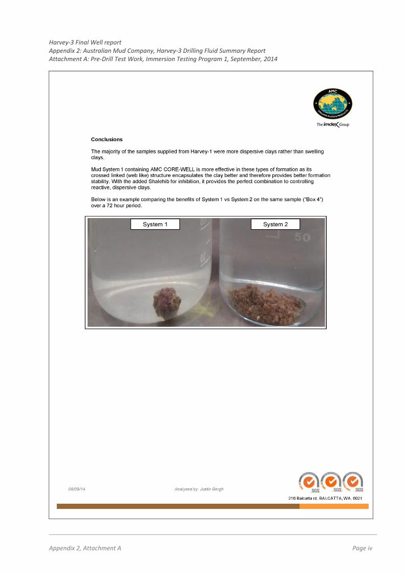
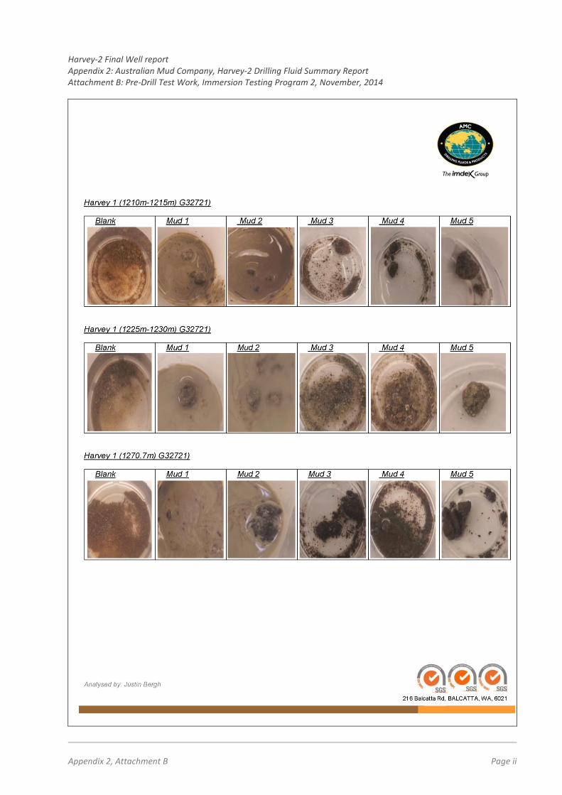
3. Harvey-1, Data Review and Geotechnical Testwork A review of the Final Well reportFinal Well report for Harvey -1, drilled in 2012, showed that the well was initially drilled with a basic Gel / PHPA system. It was evident from the recap that the integrity of the hole had been compromised due to the fact that no inhibitive fluid was used. To further address these issues, samples from some of the more challenging sections in Harvey-1 were collected from the GSWA Perth Core Library and forwarded to AMC’ Perth Laboratory for further analysis. The sampling program encountered some difficulties in finding cutting samples that could be could be considered truly representative of the broader formation intervals and were also sufficiently stable and of sufficient volume to conduct meaningful laboratory tests. Immersion and integrity tests of the samples were conducted in two stages in September and November, 2014. Sample intervals and test fluid combinations for the programs are shown in Table 1 and Attachments A and B provide photographic records of the test work observations over zero, 3-hour and 72-hour intervals.
Table 1: Sample intervals and fluid combinations selected for Phase 1 and Phase 2 test work on historic Harvey-1 cuttings and core
AMC Test 1 (cuttings only) (September, 2014)
AMC Test 2 (sectioned core samples) (November, 2014)
Sam
ple
Inte
rval
H1 1269 to 1270m H1 1270 to 1272m H1 1276 to 1278m H1 1333 to 1334m Box 4, 5, 13, 14, 15, 16, 17.
495 to 510m 675 to 690m 1210 to 1215m 1225 to 1230m 1270.7m 1277m 1333.3m 1340 to 1345m
Test
Flu
id C
ombi
natio
ns
Solution 1: 1.5kg COREWELL + 3kg PAC L + 1% SHALEHIB ULTRA Solution 2: 2.5kg PAC R + 3kg PAC L + 3kg CLAY DOCTOR + 1% SHALEHIB ULTRA
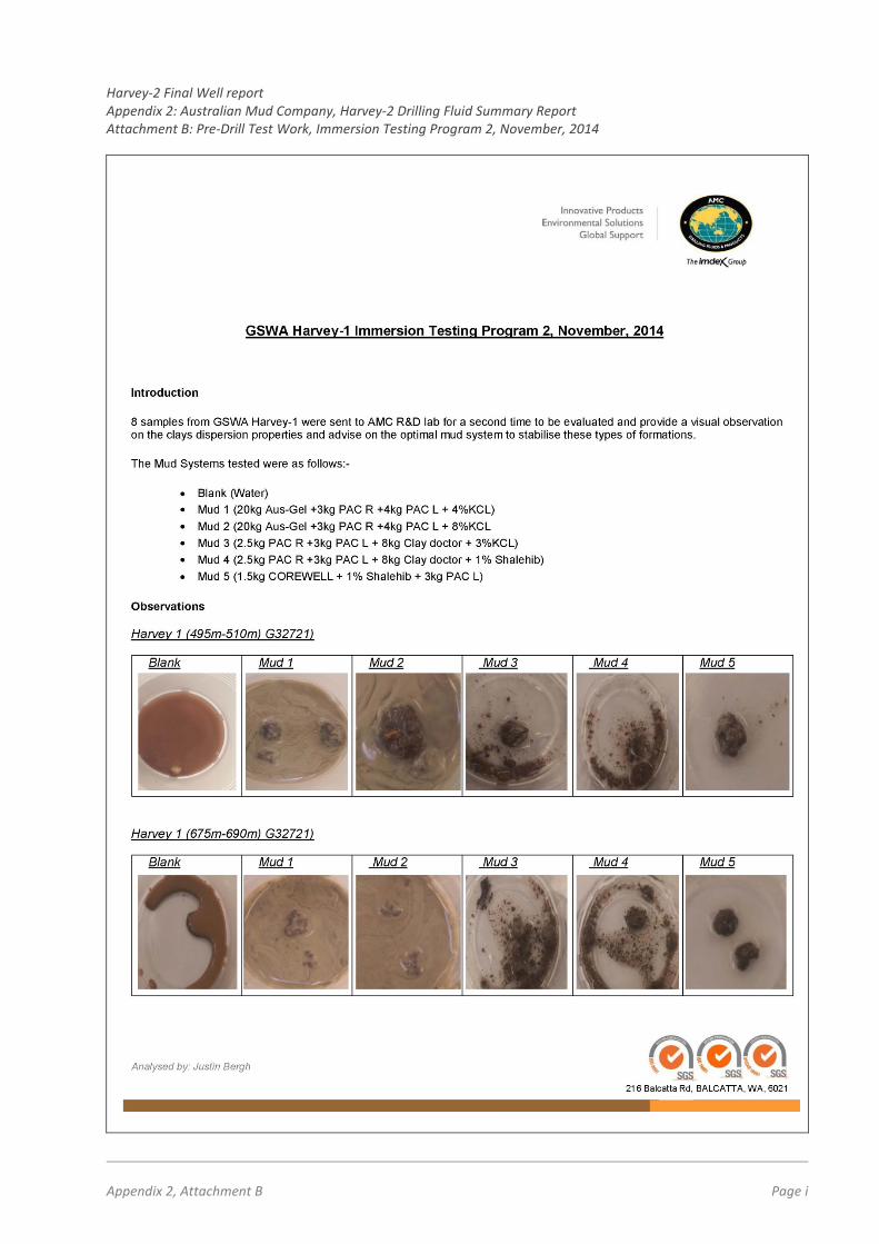
Blank: (Water) Mud 1: 20kg Aus-Gel +3kg PAC R +4kg PAC L + 4%KCl Mud 2: 20kg Aus-Gel +3kg PAC R +4kg PAC L + 8%KCl Mud 3: 2.5kg PAC R +3kg PAC L + 8kg Clay doctor + 3%KCl Mud 4: 2.5kg PAC R +3kg PAC L + 8kg Clay doctor + 1% SHALEHIB Mud 5: 1.5kg COREWELL + 1% SHALEHIB + 3kg PAC L
Results from both phases of test work (refer Attachments A and B) showed that the clays encountered in Harvey-1 were more dispersive than swelling in nature. The best containment results came from AMC’s CORE-WELL based system, which is a premium encapsulating agent.
Harvey-3 Final Well report Appendix 2: Australian Mud Company, Harvey-3 Drilling Fluid Summary Report
Appendix 2 Page 3
4. “Make-Up” Water Analysis In addition to formation integrity testing, the “make-up” water to be used in the mud program from the on-site water bore was analysed with results as follows:
5. Drilling Fluid Proposal AMC’s original drilling fluid proposal for both Harvey-2 and for Harvey-3 envisaged a two-component program for each well as follows:
• For the rotary pre-collar section - a conventional gel/polymer mix was recommended to give the best hole cleaning characteristics and to allow good filtrate control as well as hole stabilisation
• From the start of coring, utilisation of the CORE-WELL based clay-inhibiting system were recommended with KCl included as an ancillary item (at lower properties that used in Harvey 1). The rationale was that the proactive approach to protecting the formation would reduce the percentage of KCl required to control the formation. A contingency was also allowed in the mud program for adding a weighting agent (Sodium Chloride) to the system to obtain a mud weight similar to that of Harvey-1 if needed.
The mud system from the second geotechnical test program (i.e., 1.5kg COREWELL + 1% SHALEHIB + 3kg PAC-L) was selected as the drilling fluid of choice for the cored section of the wells. In addition to the system’s superior encapsulating properties, it also had potential environmental benefits of limiting of chloride addition to ground-water. The lower chloride content would also result in greater ease and reduced costs of disposal at conventional refuse facilities. Although the COREWELL (powder), SHALEHIB (fluid) and PAC-L (powder) mud system was a three-part mix, the overall reduced product volumes and reduced corrosive character were considered advantageous and less onerous to mix than a chloride-based system. Whilst drilling Harvey-2, due to various formational, operational and hole-stability issues encountered in the hole, the originally proposed fluid system was changed at 409m to a conventional weighted mud system with KCl as the principle inhibiter and weighting agent. Details of the drilling fluid change and ongoing mud issues encountered in Harvey-2 are discussed in Russell and Pollock (October 2015). The lessons learned from Harvey-2 were subsequently incorporated into a revised proposal for Harvey-3, details of which follow:-
• For the rotary pre-collar section - a conventional gel/polymer mix was recommended to give the best hole cleaning characteristics and to allow good filtrate control as well as hole stabilisation.
• For the cored section, a KCl/polymer mud system would be run with an approximate mud weight of 10
lb/gal. This would provide sufficient inhibition and weight to counteract any formational pressure zones that were encountered in Harvey-2.
Harvey-3 Final Well report Appendix 2: Australian Mud Company, Harvey-3 Drilling Fluid Summary Report
Appendix 2 Page 4
6. Mud Program Operations 6.1 Pre-Collar Section (0 – 588m) Depth / Hole Size : 0-74m / 12⅛” Mud Type : Gel/Polymer (as per AMC proposal) Fluid system used : Soda Ash 0.5 kg/m³
AUS GEL XTRA 15 – 20 kg/m3 AMC PAC L 2.0 – 3.0 kg/m³ AMC PAC R 1.5 – 2.0 kg/m3 SODIUM BICARBONATE 2.0 kg/m3 pre-treatment
The 12⅛” section was completed successfully with no anomalies recorded. Depth / Hole Size : 74-588m / 8½” Mud Type : Weighted KCl/Polymer Fluid system used : Soda Ash 0.5 kg/m³
Due to a change in the hole parameters for the ‘intermediate’ casing section of the mud rotary portion of the hole ( from 250 metres to 588 metres), it was decided to change the fluid system over to KCl/Polymer. This was to provide additional inhibition and hole stabilisation and to reduce the effects of the pressured shales experienced in Harvey-2. The 8½” section was completed successfully with no anomalies recorded. 6.2 Cored Section (588 -1550m) Depth / Hole Size : 588 – 1462m/SQ : 1462 - 1550m/HQ Mud Type : Weighted PAC/KCl Revised Fluid system : Soda Ash 0.5 kg/m³
AMC PAC L 3.0 – 4.0 kg/m³ AMC PAC R 2.0 – 2.5 kg/m3 KCl 100.0 – 220.0 kg/m3
Coring continued as per Harvey-2 with continued fluid losses and fluid dilution rates with additional fluid being added at a rate of 1500 to 3000 litres per shift depending on the losses encountered. Loss circulation material was continuously added to try and minimise these losses (Table 2).
Harvey-3 Final Well report Appendix 2: Australian Mud Company, Harvey-3 Drilling Fluid Summary Report
443200 28900 50000 55500 At approximately 1340m, fluid loss through seepage began to increase to an unacceptable level and it appeared that the fluid system was beginning to overbalance the formation pressures, losing up to 8000 litres of fluid per shift. To minimise this it was decided that the mud weight would systematically be lowered from 10.0 lb/gal to 9.2 lb/gal over several days, to reduce the equivalent circulating densities (Table 3).
This process was done slowly so as not to ‘shock’ the hole and to reduce the possibility that reducing the mud weight may also cause the formation to start to squeeze in. Once a mud weight of 9.2 lb/gal was reached the amount of fluid loss had reduced and the effect of overbalancing had lessened dramatically. At 1462m on May 27 the drill pipe became stuck. There was still 100% circulation and the fluid parameters (Table 5) were within acceptable limits for the type of drilling and available equipment on site. It appeared that the drill pipe had become differentially stuck. The mud weight was lowered to 8.85 lb/gal to try and further reduce the ECD. After consultation between DDH1 and AMC, two paths of action were decided upon;
1. placing a spotting fluid around the suspected stuck zone and, 2. replacing the fluid system with unweighted mud.
The spotting fluid was to be placed around the base of the drill pipe to the interface of the target formation, covering an approximate 83m interval of drill pipe. The spotting fluid consisted of:
• 1400 litres of existing mud • 75 litres of LIQUISPERCE • 75 litres of PENETROL XTRA • 100 litres of AUS DET XTRA
The spotting fluid was displaced with 18000 litres of fluid and left for 2 hours, then worked on for a shift, displacing 200 litres of spotting fluid every hour until all the spotting fluid was displaced from the drill pipe. The following shift, another pill was displaced and the process was repeated to no avail.
Harvey-3 Final Well report Appendix 2: Australian Mud Company, Harvey-3 Drilling Fluid Summary Report
Appendix 2 Page 6
The existing active fluid system was replaced with approximately 35000 litres of a non-weighted fluid (Table 4) and the weighted fluid was stored on site for later use. The replacement fluid consisted of:
• Soda Ash 0.5 kg/m3 • AMC PAC R 2.0 – 3.0 kg/m3 • AMC PAC L 1.0 – 2.0 kg/m3 • SHALEHIB ULTRA 3% by fluid volume
Table 4: Initial non-weighted fluid volumes
Sections Volumes Litres (approximate)
Annular volume 7” casing, 0 – 588m 5500 Annular volume PWT, 588 – 1462m 2270 PWT internal volume, 0- 1462m 18500 Open Hole volume,0 – 75m 170 Surface pit volumes (min. requirement) 8660 Total Volume 35,100 A further 15000 litres were added before a reduced mud weight of 8.4 lb/gal was seen in the flow line. This indicated that there was significant washout present. The rods were continuously worked as the lighter fluid was circulated. On May 29, the rods began to move, the fluid weight was increase to 9.0 lb/gal and the pipes were subsequently removed from the hole for wireline logging. The logging attempt was abandoned as the hole was bridged at 970m. On running back into the hole, several more bridges were encountered, possibly due to formation squeezing because of the decreased mud weight. To remedy this, the mud weight was brought back up to 10.0lb/gal and calcium carbonate was added to the system to try to reduce fluid loss. Once hole stability returned, the section was cased-off and drilling continued HQ to TD. During this interval mud weight was maintained at 10.0 lb/gal and no further issues were encountered. 7. Materials Consumption and Cost Analysis of the Harvey-3 Drilling Fluid Program A review of programmed vs actual materials consumption in Harvey-3 is presented in Table 6 and overall variance in costs for the original (un-weighted) and revised (weighted) programs is shown in Table 7. The overall increase in hole costs can be attributed to:
• The increased length of time on the hole, which increased fluid consumption through losses,
• Increased hole diameter from PQ to SQ,
• Greater than expected fluid losses in the more permeable zones in Harvey-3 than experienced in Harvey-2, due to high ECD experienced from running a weighted fluid system,
• Continued use of potassium chloride as the weighting agent,
• A higher retention of solids than expected which caused an increase in product usage through
depletion and additional fluid dumping (55,500 litres).
Harvey-3 Final Well report Appendix 2: Australian Mud Company, Harvey-3 Drilling Fluid Summary Report
Appendix 2 Page 7
Table 5: Fluid properties prior to and after stuck pipes
NB: Programmed quantity includes weighting agent (NaCl) and inhibitor (KCl) from the weighted program)
Harvey-3 Final Well report Appendix 2: Australian Mud Company, Harvey-3 Drilling Fluid Summary Report
Appendix 2 Page 8
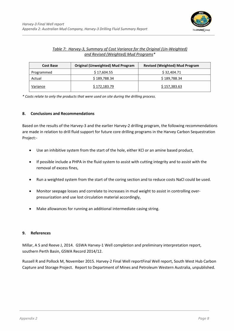
Table 7: Harvey-3, Summary of Cost Variance for the Original (Un-Weighted) and Revised (Weighted) Mud Programs*
Cost Base Original (Unweighted) Mud Program Revised (Weighted) Mud Program
Programmed $ 17,604.55 $ 32,404.71 Actual $ 189,788.34 $ 189,788.34
Variance $ 172,183.79 $ 157,383.63
* Costs relate to only the products that were used on site during the drilling process. 8. Conclusions and Recommendations Based on the results of the Harvey-3 and the earlier Harvey-2 drilling program, the following recommendations are made in relation to drill fluid support for future core drilling programs in the Harvey Carbon Sequestration Project:-
• Use an inhibitive system from the start of the hole, either KCl or an amine based product,
• If possible include a PHPA in the fluid system to assist with cutting integrity and to assist with the removal of excess fines,
• Run a weighted system from the start of the coring section and to reduce costs NaCl could be used.
• Monitor seepage losses and correlate to increases in mud weight to assist in controlling over-pressurization and use lost circulation material accordingly,
• Make allowances for running an additional intermediate casing string. 9. References Millar, A S and Reeve J, 2014. GSWA Harvey-1 Well completion and preliminary interpretation report, southern Perth Basin, GSWA Record 2014/12.
Russell R and Pollock M, November 2015. Harvey-2 Final Well reportFinal Well report, South West Hub Carbon Capture and Storage Project. Report to Department of Mines and Petroleum Western Australia, unpublished.
Harvey-3 Final Well report Appendix 2: Australian Mud Company, Harvey-3 Drilling Fluid Summary Report Attachment A: Pre-Drill Test Work, Immersion Testing Program 1, September, 2014
Appendix 2, Attachment A Page i
Harvey-3 Final Well report Appendix 2: Australian Mud Company, Harvey-3 Drilling Fluid Summary Report Attachment A: Pre-Drill Test Work, Immersion Testing Program 1, September, 2014
Appendix 2, Attachment A Page ii
Harvey-3 Final Well report Appendix 2: Australian Mud Company, Harvey-3 Drilling Fluid Summary Report Attachment A: Pre-Drill Test Work, Immersion Testing Program 1, September, 2014
Appendix 2, Attachment A Page iii
Harvey-3 Final Well report Appendix 2: Australian Mud Company, Harvey-3 Drilling Fluid Summary Report Attachment A: Pre-Drill Test Work, Immersion Testing Program 1, September, 2014
Appendix 2, Attachment A Page iv
Harvey-2 Final Well report Appendix 2: Australian Mud Company, Harvey-2 Drilling Fluid Summary Report Attachment B: Pre-Drill Test Work, Immersion Testing Program 2, November, 2014
Appendix 2, Attachment B Page i
Harvey-2 Final Well report Appendix 2: Australian Mud Company, Harvey-2 Drilling Fluid Summary Report Attachment B: Pre-Drill Test Work, Immersion Testing Program 2, November, 2014
Appendix 2, Attachment B Page ii
Harvey-2 Final Well report Appendix 2: Australian Mud Company, Harvey-2 Drilling Fluid Summary Report Attachment B: Pre-Drill Test Work, Immersion Testing Program 2, November, 2014