Hazaridous Waste Reduction in the Aerospace Industry I. Iinproved housekeeping and maintenance practices, incineration, and the substitution of raw materials are among the approaches aemvace companies are taking to reduce hazardous wastes. Stephen P. Evanoff, General Dynamics, Fort Worth, TX 76101 he aerospace industry generates a broad array of air emissions and hazardous waste solids, liquids, and T sludges during the processing of aluminum, tita- nium, composites, and other materials into aircraft and other system components. Due to the maturity of the man- ufacturing facilities in this industry, most of the chemical manufacturing processes incorporate 20- to 30-year-old technology and hardware. These older processes tend to generate large amounts of hazardous wastes and air emis- sions. Until the mid-l980s, most companies relied heavily on disposal by landfilling and deep well injection. As of the mid-1980s typical manufacturers generated haz- ardous waste on the order of 2 to 4 Ib (0.9 to 1.8 kg) of waste per pound (per 0.45 kg) of aircraft. Land disposal laws phased in between 1986 and 1990 are having a significant impact on aerospace industry production and material man- agement practices. The laws currently restrict and will eventually eliminate land disposal, escalating off-site treat- ment and disposal costs 5 to 10 times. Moreover, genera- tors will be financially liable under the so-called cradle-to- grave liabilities enacted under the Resources Conservation and Recovery Act (RCRA). The General Dynamics Corp. S. P. Evawff, an engjnaering spretollrt in the Fort k#rth TerasMv& auntatha dnewmateriabthattsdvrclrorprdwt rwstesandemk hs. Chairman of the division's Hazardous Waste Management (hudttee, he abo arms 01 U.S. repmsentative to the UnUed Nu- b Envinmment Apo14n, Sobents Review Committee under the M"d- a WU@ among more than 100 countries to re- cducr ozone-dqnkting He eamedh&irChEd4gw at the IUlkdr Institute d - and h& MSXE &me at the Udv. of hh. a b n ~ ~ ~ & J w p o n d b f e ~ ~ e n t d ~ program to achieve "zero discharge," which was initiated in 1985, is driven by the desire to eliminate liability associated with hazardous waste generation and disposal. Environmental and chemical process experts from the leading aerospace manufacturers have convened annually since 1986 to exchange information on waste reduction R&D and waste management strategies. Exchange of data between aerospace company R&D centers now occurs regu- larly in the areas of solvent substitution, volatile organic compound (VOC) emission reduction, and alternative metal finishing process technology development. There is also an industry-wide effort to identify and develop strategies for eliminating chromium from aerospace metal finishing pro- cesses. Chromium is one of the largest sources of hazardous waste in the aerospace industry. These efforts have resulted in the near elimination of all forms of land disposal at Air Force Plant No. 4 and a reduc- tion in hazardous waste generation at General Dynamics of 50% over the 1984 baseline, even though production nearly doubled by 1988. The General Dynamics Pomona Division has reported a reduction of Over 90% in hazardous waste generation since 1984. RCRA framework. The key RCRA legislation and the affected aerospace manufacturing processes and waste- streams are listed in Table 1. Laws slated for enactment through 1990 are included. Many firms assume that all forms of land disposal will be prohibited after 1990. The 1984 RCRA amendment included a national policy statement that said, "wherever feasible, the generation of hazardous waste is to be reduced or eliminated. .,. ." A 1986congressional study went further, stating, "those who
Transcript
I
Hazaridous Waste Reduction in the
Aerospace Industry I .
Iinproved housekeeping and maintenance practices, incineration, and the substitution of raw materials are among the approaches aemvace
companies are taking to reduce hazardous wastes.
Stephen P. Evanoff, General Dynamics, Fort Worth, TX 76101
he aerospace industry generates a broad array of air emissions and hazardous waste solids, liquids, and T sludges during the processing of aluminum, tita-
nium, composites, and other materials into aircraft and other system components. Due to the maturity of the man- ufacturing facilities in this industry, most of the chemical manufacturing processes incorporate 20- to 30-year-old technology and hardware. These older processes tend to generate large amounts of hazardous wastes and air emis- sions. Until the mid-l980s, most companies relied heavily on disposal by landfilling and deep well injection. As of the mid-1980s typical manufacturers generated haz-
ardous waste on the order of 2 to 4 Ib (0.9 to 1.8 kg) of waste per pound (per 0.45 kg) of aircraft. Land disposal laws phased in between 1986 and 1990 are having a significant impact on aerospace industry production and material man- agement practices. The laws currently restrict and will eventually eliminate land disposal, escalating off-site treat- ment and disposal costs 5 to 10 times. Moreover, genera- tors will be financially liable under the so-called cradle-to- grave liabilities enacted under the Resources Conservation and Recovery Act (RCRA). The General Dynamics Corp.
S. P. Evawff, an engjnaering spretollrt in the Fort k#rth TerasMv&
auntatha dnewmateriabthattsdvrclrorprdwt rwstesandemk h s . Chairman of the division's Hazardous Waste Management (hudttee, he abo a r m s 01 U.S. repmsentative to the UnUed Nu- b Envinmment Apo14n, Sobents Review Committee under the M"d- a WU@ among more than 100 countries to re- cducr ozone-dqnkting He eamedh&irChEd4gw at the IUlkdr Institute d- and h& MSXE &me at the Udv. of hh.
a b n ~ ~ ~ & J w p o n d b f e ~ ~ e n t d ~
program to achieve "zero discharge," which was initiated in 1985, is driven by the desire to eliminate liability associated with hazardous waste generation and disposal.
Environmental and chemical process experts from the leading aerospace manufacturers have convened annually since 1986 to exchange information on waste reduction R&D and waste management strategies. Exchange of data between aerospace company R&D centers now occurs regu- larly in the areas of solvent substitution, volatile organic compound (VOC) emission reduction, and alternative metal finishing process technology development. There is also an industry-wide effort to identify and develop strategies for eliminating chromium from aerospace metal finishing pro- cesses. Chromium is one of the largest sources of hazardous waste in the aerospace industry.
These efforts have resulted in the near elimination of all forms of land disposal at Air Force Plant No. 4 and a reduc- tion in hazardous waste generation at General Dynamics of 50% over the 1984 baseline, even though production nearly doubled by 1988. The General Dynamics Pomona Division has reported a reduction of Over 90% in hazardous waste generation since 1984. RCRA framework. The key RCRA legislation and the
affected aerospace manufacturing processes and waste- streams are listed in Table 1. Laws slated for enactment through 1990 are included. Many firms assume that all forms of land disposal will be prohibited after 1990.
The 1984 RCRA amendment included a national policy statement that said, "wherever feasible, the generation of hazardous waste is to be reduced or eliminated. ., . ." A 1986congressional study went further, stating, "those who
.
Table 1. Summary of key land dsp-al regulations.
Land DIs&l Restriction (Solvents, Sludges)
Land Disposal Restriction (“Califomla LM’3
Land Disposal and Deep Well Injection Restrictions
“First-Third” Wastes
“Second-Third” Wastes (n of l isted Wastes)
(% of Listed Wastes)
Land Disposal and Deep Well Injection Restrictions
Remaining Llsted and Characterlstic Wastes
Ail “Third-Third” Wastes
Effective Date Nov. 8, 1986
July 8, 1987
Aug. 8,1988
Aug. 8,1989
May 8,1990
Affected Aerospace
Manufacturing Process
Degreasing
Degreaslng, All Surface Finishing
All
All
All
have implemented waste reduction effectively, generally see it as a way to improve profitability and competitiveness.” A State of California study takes this position: “waste reduc- tion as opposed to waste management is the financially and environmentally preferred strategy. At the very least, source reduction and on-site treatment free generators from the risk and expense of transportation.” Associated liability is- sues and new disposal laws have led firms to consider near- term elimination of land disposal and longterm zero haz- ardous waste discharge (defined as no off-site shipment of manifested hazardous wastes).
Consistent with these goals, the following source reduc- tion methods will be discussed from an aerospace industry perspective: material conservation, material recoverylrecy- cle, and material and process substitution. Combinations of these source reduction concepts plus limited use of waste destruction technologies can eliminate most hazardous wastes from aerospace production facilities.
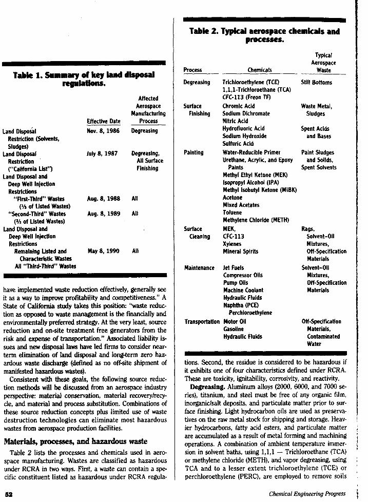
Materials, processes, and hazardous waste Table 2 lists the processes and chemicals used in aero-
space manufacturing. Wastes are classified as hazardous under RCRA in two ways. First, a waste can contain a spe- cific constituent listed as hazardous under RCRA regula-
sa
k ,
~
Table 2. Typical aerospace chemkals and w-0
Typical Aerospace
Waste ~- Process Chemicals
Degreaslng
Surface Finishing
Painting
Surface Cleaning
Maintenance
Trichloroethylene (TCD Still Bottoms l,l,l-Trichloroethane (TCA) CFC-113 (Freon TF) Chromic Acid Waste Metal, Sodium Dichromate Sludges Nitric Acid Hydrofluoric Acid Spent Acids Sodium Hydroxide and Bases Sulfuric Acid Water-Reducible Primer Paint Sludges Urethane, Acrylic, and Epoxy and Solids,
Perchloroethylene Transportation Motor Oil Off-Specification
Gasoline Materiais, Hydraulk Fluids Contaminated
Water
tions. Second, the residue is considered to be hazardous if it exhibits one of four characteristics defined under RCRA. These are toxicity, ignitability, corrosivity, and reactivity. Degreasing. Aluminum alloys (2000, 6oO0, and 7000 se-
ries), titanium, and steel must be free of any organic film, inorganiclsalt deposits, and particulate matter prior to sur- face finishing. Light hydrocarbon oils are used as preserva- tives on the raw metal stock for shipping and storage. Heav- ier hydrocarbons, fatty acid esters, and particulate matter are accumulated as a result of metal forming and machining operations. A combination of ambient temperature immer- sion in solvent baths, using 1,1,1 - Trichloroethane (TCA) or methylene chloride (METH), and vapor degreasing, using TCA and to a lesser extent trichloroethylene (TCE) or perchloroethylene (PERC), are employed to remove soils
Chemical Engineering prosresS
11 , 1 1
7 isT -
a“71 a TC e x i n- CL
str e
sir
(cc trc
1 U€ (“
c
1
ti
J<
SI1
e cr
r
tn C:
..,,
C:
m t -
r
A
H
1 . 1
1 3.
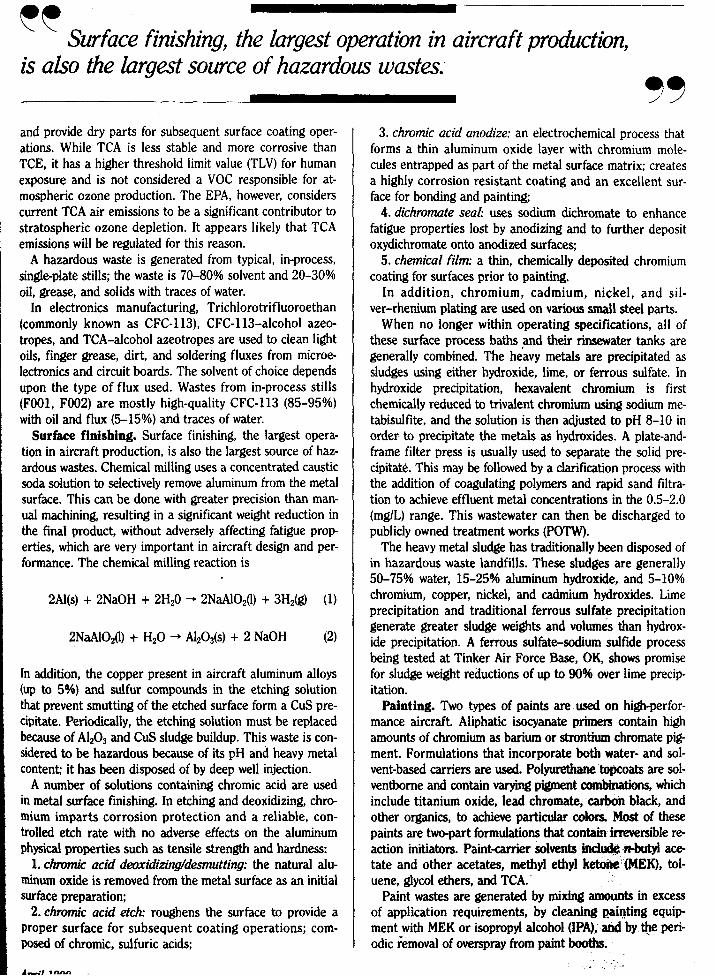
Surface finishing, the largest operation in aircraft productiun, cc is also the largest source of hazardous wastes.
93 and provide dry parts for subsequent surface coating oper- ations. While TCA is less stable and more corrosive than TCE, it has a higher threshold limit value (TLV) for human exposure and is not considered a VOC responsible for at- mospheric ozone production. The EPA, however, considers current TCA air emissions to be a significant contributor to stratospheric ozone depletion. It appears likely that TCA emissions will be regulated for this reason.
A hazardous waste is generated from typical, in-process, single-plate stills; the waste is 70430% solvent and 20-30% oil, grease, and solids with traces of water.
In electronics manufacturing, Trichlorotrifluoroethan (commonly known as CFC-113), CFC-113-alcohol azeo- tropes, and TCA-alcohol azeotropes are used to clean light oils, finger grease, dirt, and soldering fluxes from microe- lectronics and circuit boards. The solvent of choice depends upon the type of flux used. Wastes from in-process stills (F001, F002) are mostly high-quality CFC-113 (85-95%) with oil and flux (5-15%) and traces of water.
Surface finishing. Surface finishing, the largest opera- tion in aircraft production, is also the largest source of haz- ardous wastes. Chemical milling uses a concentrated caustic soda solution to selectively remove aluminum from the metal surface. This can be done with greater precision than man- ual machining, resulting in a significant weight reduction in the final product, without adversely affecting fatigue prop- erties, which are very important in aircraft design and per- formance. The chemical milling reaction is
2Al(s) + 2NaOH + 2Hz0 -. 2NaAlO2(1) + 3H2@ (1)
2NaAlO2(1) + HzO + A1203(s) + 2 NaOH (2)
In addition, the copper present in aircraft aluminum alloys (up to 5%) and sulfur compounds in the etching solution that prevent smutting of the etched surface form a CuS pre- cipitate. Periodically, the etching solution must be replaced because of A&O3 and CuS sludge buildup. This waste is con- sidered to be hazardous because of its pH and heavy metal content; it has been disposed of by deep well injection.
A number of solutions containing chromic acid are used in metal surface finishing. In etching and deoxidizing, chro- mium imparts corrosion protection and a reliable, con- trolled etch rate with no adverse effects on the aluminum physical properties such as tensile strength and hardness:
1. chromic acid deoxidi2ing/dmutting: the natural alu- minum oxide is removed from the metal surface as an initial surface preparation;
2. chromic acid etch: roughens the surface to provide a Proper surface for subsequent coating operations; com- posed of chromic, sulfuric acids:
A-*: I-
3. chromic acid anodize: an electrochemical process that forms a thin aluminum oxide layer with chromium mole- cules entrapped as part of the metal surface matrix; creates a highly corrosion resistant coating and an excellent sur- face for bonding and painting;
4. dichromate seal: uses sodium dichromate to enhance fatigue properties lost by anodizing and to further deposit oxydichromate onto anodized surfaces,
5. chemical film: a thin, chemically deposited chromium coating for surfaces prior to painting.
In addition, chromium, cadmium, nickel, and sil- ver-rhenium plating are used on various small steel parts.
When no longer within operating specifications, all of these surface process baths and their rinsewater tanks are generally combined. The heavy metals are precipitated as sludges using either hydroxide, lime, or ferrous sulfate. In hydroxide precipitation, hexavalent chromium is first chemically reduced to trivalent chromium using sodium me- tabisulfite, and the solution is then adjusted to pH 8-10 in order to precipitate the metals as hydroxides. A plate-and- frame filter press is usually used to separate the solid pre- cipitate. This may be followed by a clarification process with the addition of coagulating polymers and rapid sand filtra- tion to achieve effluent metal concentrations in the 0.5-2.0 (mglL) range. This wastewater can then be discharged to publicly owned treatment works (POTW).
The heavy metal sludge has traditionally been disposed of in hazardous waste landfills. These sludges are generally 50-75% water, 15-25% aluminum hydroxide, and 5-10% chromium, copper, nickel, and cadmium hydroxides. Lime precipitation and traditional ferrous sulfate precipitation generate greater sludge weights and volumes than hydrox- ide precipitation. A ferrous sulfate-sodium sulfide process being tested at Tinker Air Force Base, OK, shows promise for sludge weight reductions of up to 90% over lime precip- itation.
Painting. Two types of paints are used on hlgh-perfor- mance aircraft. Aliphatic isocyanate primers contain high amounts of chromium as barium or strontium chromate pig- ment. Formulations that incorporate both water- and sol- vent-based carriers are used. Polyurethrtne topcoats are sol- ventbome and contain varying pigment combinations, which include titanium oxide, lead chromate, carbon black, and other organics, to achieve particular cdors. Most of these paints are two-part formulations that contain irreversible re- action initiators. Paint-carrier sobents ifdude -1 ace- tate and other acetates, methyl ethyl ketone IMEK), tol- uene, glycol ethers, and TCA.
Paint wastes are generated by mixing amounts in excess of application requirements, by cleaning Rainting equip ment with MEK or isopropyl alcohol (IPA), and by $e peri- odic removal of overspray from paint booths.
1 1
These wastes are hazardous because they contain a listed hazardous constituent, in this case Fool-005 solvents, or because of the extraction procedure (EP) toxicity of heavy metals from the pigment. Most aerospace coatings are at risk on both accounts. Solvent-based paint wastes and even waterborne paint wastes generally contain traces of listed solvents. This does not preclude land disposal unless they are mixed wastes containing specific listed solvents. Both types of paints are at risk for chromium leachability.
Hazardoh waste management companies have offered to use lime dust or cement kiln fly ash to stabilize residual solvent in order to allow continued land disposal until 1990. The difficulty in properly stabilizing a 55-gal (0.2-m3) drum of semisolid material makes the effectiveness of this method doubtful. A conservative approach in addressing both of these issues is to consider thermal destruction of all paint wastes.
Surface cleaning. The cleaning of preassembly and sub assembly aircraft components after surface finishing, prior to and during adhesive bonding or rivetting of parts, re- quires solvents that will provide an extremely clean, dry sur- face. Traditionally, high-volatility hydrocarbons, e.g., MEK- hydrocarbon blends, have been used. These materials are used to hand clean surfaces with fine-mesh cotton rags or cheesecloth. Since the mid-l980s, many companies, partic- ularly those in California, have switched to “exempt” mate- rials, mainly CFC-113 or TCA blends, to reduce total VOC emissions. Due to the urgency of the ozone depletion prob lem, use of these materials as hand-wipe solvents will be phased out in favor of lower vapor pressure solvent blends with a composite vapor pressure well below 20 mm Hg. This approach, and other innovative nonsolvent approaches to cleaning, are presently being pioneered at Boeing Aero- space, the General Dynamics Fort Worth Division, and other manufaduring facilities on the West Coast. As of Nov. 8, 1988, rag waste containing solvents in ex-
cess of concentrations listed in 40 CFR 268.32, Appendix 111, are restricted from land disposal. Because many organi- zations will switch to lowvolatility hydrocarbon solvents for hand-wipe operations, it must be recognized that these wastes will be considered hazardous and, thus, will require either treatment and recovery of all solvents (e.g., evapora- tion-condensation) or thermal destruction (e.g., incinera- tion or use as a wastederived fuel).
Maintenance. The maintenance departments at major aerospace facilities are generally responsible for the repair of plant manufacturing equipment (lathes, presses, motors, pumps, etc.) and housekeeping in the manufacturing areas. This is accomplished by the spray-and-wipe application of cleaning solvents on equipment and floors or the immersion
SI
of parts in cold cleaning tanks. Solvents employed in these applications include aliphatic naphtha, METH, PERC, and blends of these three materials known as “safety solvents.” Waste solvents recovered from these cleaning operations usually contain oil and must be handled as a hazardous waste.
Transportation. Garage work on plant support vehi- cles (repairs, oil changes, etc.) result in the generation of used oil waste, transmission fluid and fuel wastes, wuJte ethylene glycol-water mixtures, and naphtha-based cleaning solvent wastes. The solvent and fuel wastes are considered hazardous. Waste oils, although not classified as hazardous waste, are regulated for use in plant boilers but can be used for energy recovery in industrial furnaces. Interestingly, ethylene glycol is neither regulated nor classified as a baz- ardous waste.
Laboratory RGrD. Plant research laboratories generate a microcosm of all plant materials being used because their activities generally support existing and developmental bra- duction technologies. This potpourri of solvents, acids, and paint wastes represents a minute fraction of the total waste stream at any major manufacturing facility. Nevertheless, they must be managed as mandated by RCRA at large facil- ities. In most cases, mixed laboratory wastes are packaged as “lab packs” and sent for incineration or chemical. de- struction at commercial waste disposal facilities.
Material conservation A number of good housekeeping measures and produc-
tion process modifications can reduce the amount of waste materials being generated. Regularly scheduled ma$te- nance of motors, pumps, and machines can minimizevma- chine hydraulic fluid losses.
Leaking fluids are removed with a diatomaceous d r t h absorbent at most plants. The mixture can be considered hazardous based upon solvent content and leachability. Costly ($300 to 66001drum) incineration is required for disposal. Also, contamination of large, open, machine hy- draulic fluid sumps with small amounts of inadvertantly dis- posed listed solvents may cause entire oil reservoirs to be- come hazardous waste because of hazardous waste mixture rules. Incineration is required for proper disposal. Em- ployee awareness campaigns and controlled use of solvents in areas containing large oil reservoirs can prevent these occurrences.
Paint waste generation can be minimized by high-volume, low-pressure paint guns or electrostatic paint equipment to increase paint transfer efficiency. Also, using proportional paint-mixing equipment to prepare the two- or three-com- ponent paints can reduce the generation of excess hazard-
1
Chemical EngineGng Progress
Pal effi
- ous wastc howe Powc est r- of sc 19% Vi
min cutti ultir post cat0 awl can Par poir sie\ gre 7
mir fro till< mal inc
ers mz in6 ant be
Re
Ck ria e ri SF alp sic ti
de
fc Pr th
P
/
t
ca
1
ar
Paint waste can be cut in half by hQh-uolume, Zow-presswe cc paint guns or electrostatic paint equment to increase transfer efficiency, and the use of two- or threecomponent paints.
33 ous paint waste. These two techniques can decrease paint waste generation by over 50%. To achieve this reduction, however, a good deal of operator orientation is necessary. Powder coating and plasma spray technologies are the new- est means of applying coatings to surfaces without the use of solvents. Both will continue to be developed well into the 1990s.
Vapor degreaser and cold solvent cleaner wastes can be minimized by reducing the amount of machine lubricants, cutting fluids, and oils applied to parts. These materials are ultimately removed as degreaser still bottoms and are dis posed of as hazardous waste. Use of low-volume spray appli- cabrs for forming lubricants can decrease the amount of oil applied to large parts. The quality of the degreasing solvent can be monitored by simple laboratory tests that measure parameters such as acid acceptance, specific gravity, boiling point, and water content. Water separators and molecular sieve adsorbent columns can be integrated into existing de- greasers.
These techniques will maximize solvent lifespan and thus minimize the amount of waste solvent that must be bled from the system. This hazardous waste can be further dis- tilled to recover solvents, which can be recycled with the re- maining still bottoms requiring commercial hazardous waste incineration.
Air emissions can be reduced by adding mechanized cov- ers and parts hoistslconveyors to minimize drafts across the machine when loading or unloading, as well as by maintain- ing proper hoisting techniques in order to minimize drag out and disturbance of the vapor blanket All of these, which can be achieved by regular operator education and awareness, can reduce solvent losses up to 50%.
Recyclelrecovery technologies Equipment and techniques can be applied to existing
chemical processes to minimize the amount of spent mate- rial, hazardous waste, and fugitive emissions that are gen- erated. As discussed previously, the largest sources of aero- space industry wastes are chemical etching and milling of aluminum, eiectroplatinghodizing, and chemical conver- sion coating of aluminum; painting and degreasing opera- tions also generate large amounts of solvent wastes.
The simplest resource recovery options are those being developed through hazardous waste exchanges being set up around the country. These regional and state-operated in- formation services provide contacts for exchanging waste Products that can serve as feedstocks for other industries or that can be consumed by commercial recyclers.
Surface finishing. A number of technologies can be ap- Plied to recover metallic acids and bases for either direct re-
cycling or treatment and reuse. Chemical milling solutions. The waste products from
existing aerospace processes can, in some cases, be used as a direct process feedstock in smelting and metal refining for two reasons: 1) the quality of spent caustic is so high that aerospace waste caustic meets aluminum producers’ feed material requirements and 2) the h& purity and concen- tration of alumina in a spent milling solution is a valuable resource for aluminum recovery.
The most effective recycling technology for in-process re- cycling of caustic etch solutions consists of a proprietary re- generation technology containing a semipermeable mem- brane filtration system capable of operating at an extremely high pH. The system concentrates the aluminum and cog per derived from common aerospace alloys in a recoverable form and recycles the regenerated caustic solution.
McDonnell-Douglas (St. Louis, MO) and Wing (Wichita, KS) have been successful in installing and operating regen- eration systems. A 90% reduction in hazardous waste sludges can be realized. The metal content of any sludges generated by this process is restricted to aluminum, tita- nium, and small amounts of copper, depending on the al- loys involved. This heavy metal by-product could be incor- porated into existing industrial resource recovery programs. Companies located in Japan, France, and the United States are marketing this recycling technology.
Chromic acid anodize, deoxidize, and etch solutions. Sludges from hydroxide precipitation of aerospace metal process wastes have the following general composition by weight water, 65-75%; A1203, 10-15%; organic (coagulat- ing polymer), 5-10%; CuO, 2 4 % ; Cr203, 1-5%; Fe03 and mineral salts, 1-3%.
Under RCRA, these sludges can potentially be recycled as a direct feedstock substitute for the days and shales, which are a source of alumina and silica, in the manufactwe of ce- ment because their chemical and physical properties are similar. (Traces of the heavy metals have been reported to improve cement strength.) Other industries that can accept spent sludges (or their precursor solutions) include indus- trial smelters (for the recovery of copper from ore-grade wastes (Cu > 2.5%) and the wolmanizing industry (for us- ing the spent acids in treatment of special outdoorgrade lumber, e.g., telephone poles, railroad tks, etc.). In these two cases, the waste is a manifested hazardous waste when leaving the generator‘s facility. There is a potential future liability for the generator because the receiving industry generates additional hazardous by-products that must be properly disposed; the recipients could also be liable for fu- ture action because of the Comprehensive Environmental Response Compensation and Liability Act (CI3RCLA)jf the
. .-
W O ( I K I N Q S O L U T I O N
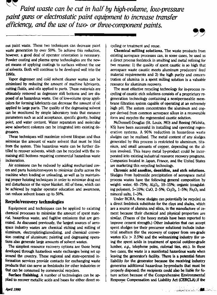
Figure 1. In situ ekchpdiatydr dclrrwnotes.
facilities are operated improperly. Waste sludges and heavy-metal-contaminated water can be
virtually eliminated. Chromic acid anodize and etch proces baths eventually build up concentrations of Cr3+, which is reduced from the original CrOd2- over time, and other trace cations. Electrodialysis technologies use semipermeable membranes and controlled electrical potential across the membrane to cause ions to selectively diffuse through the membrane, where they can either be removed and precipi- tated, while the Cr3+ solution in the process solution is ox- idized to regenerate CrOt-.
Figure 1 illustrates the concept, which can be designed to operate by continually drawing a slip stream from the main bath and returning the purified solution while removing and concentrating the unwanted chemical species.
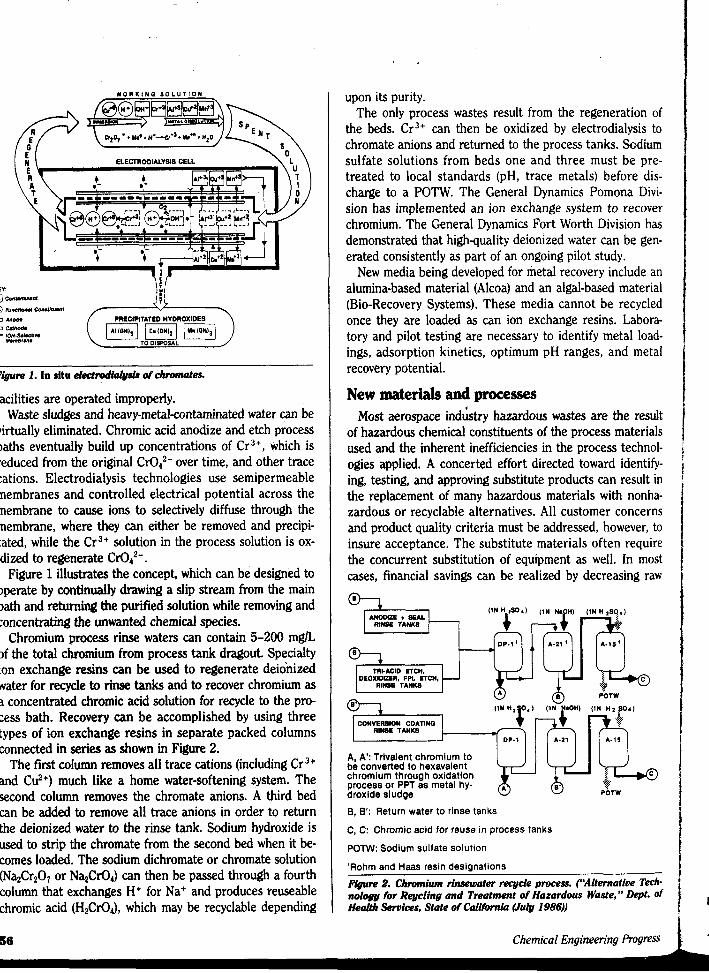
Chromium process rinse waters can contain 5-200 mglL of the total chromium from process tank dragout. Specialty ion exchange resins can be used to regenerate deionized water for recycle to rinse tanks and to recover chromium as a concentrated chromic acid solution for recycle to the pro- cess bath. Recovery can be accomplished by using three types of ion exchange resins in separate packed columns connected in series as shown in Figure 2.
The first column removes all trace cations (including Cr3+ and Cuz+) much like a home water-softening system. The second column removes the chromate anions. A third bed can be added to remove all trace anions in order to return the deionized water to the rinse tank. Sodium hydroxide is used to strip the chromate from the second bed when it be- comes loaded. The sodium dichromate or chromate solution (NazCr207 or NazCr04) can then be passed through a fourth column that exchanges H+ for Na+ and produces reuseable chromic acid (H2Cr04), which may be recyclable depending
86
upon its purity. The only process wastes result from the regeneration of
the beds. Cr3+ can then be oxidized by electrodialysis to chromate anions and returned to the process tanks. Sodium sulfate solutions from beds one and three must be pre- treated to local standards (pH, trace metals) before dis- charge to a POTW. The General Dynamics Pomona Divi- sion has implemented an ion exchange system to recover chromium. The General Dynamics Fort Worth Division has demonstrated that high-quality deionized water can be gen- erated consistently as part of an ongoing pilot study.
New media being developed for metal recovery include an alumina-based material (Alcoa) and an algal-based material (Bio-Recovery Systems). These media cannot be recycled once they are loaded as can ion exchange resins. Labora- tory and pilot testing are necessary to identify metal load- ings, adsorption kinetics, optimum pH ranges, and metal recovery potential.
New materials and processes Most aerospace indktry hazardous wastes are the result
of hazardous chemical constituents of the process materials used and the inherent inefficiencies in the process technol- ogies applied. A concerted effort directed toward identify- ing, testing, and approving substitute products can result in the replacement of many hazardous materials with nonha- zardous or recyclable alternatives. All customer concerns and product quality criteria must be addressed, however, to insure acceptance. The substitute materials often require the concurrent substitution of equipment as well. In most cases, financial savings can be realized by decreasing raw
DP-1’
DEOXIDIZER. PPI. ETCH, RINSE TANKS
I W
COWVERSION COAnNQ ‘iN “‘0”‘ RINSE TANKS
A, A’: Trivalent chromium to be converted to hexavalent chromium through oxidation process or PPT as metal hy. droxide sludge
B, 6’: Return water to rinse tanks
A - Z i ’ 4J
C, C: Chromic acid for reuse in process tanks
P O W : Sodium sulfate solution
‘Rohm and Haas resin designations
Figure 2. Chromium rinsewater reeycle process. (“Alternative Tech- nology for Rqcling and Treatment of Hazardous Waste, ’* Oppt. of Health Services, State of Gdifomia (July 1986))
Chemical Engineering Progress
c
‘ t e4 -
mat incr bill neI cost itie
I and cor be clea the:”
1 spa and bui’ 5-’ ical 49-‘
c
-
CO!
* ) j.
* N
* F * E * D
Waf * D
L
C’
M I
- APr
1 I I
! q k ; ? pre- f is-
]vi- cover
F 1: :; 1:; I pi I ' I
"F
I 1 .i
:1 J E
ion of
1-
de an
tbora- 1-
er Idis
ult in
er, to quire
"p li
Tupene-water emulsions can substitute for CFC-113 in certain electronia degreasing operations
material and disposal costs, improving product quality, and increasing process efficiencies. The long-term financial lia- bilities of hazardous waste disposal and exposure to person- nel in the workplace are not readily factored into traditional cost-effectiveness accounting schemes; both potential liabil- ities can be eliminated with proper material substitution.
Degreasing and surface cleaning. Chlorinated solvent and CFC-113 vapor degreasing of metals and electronics components and cold-immersion cleaning of metal parts can be replaced by a variety of alkaiineldetergent and emulsion cleaners and other hydrocarbon substitutes. Table 3 defines these categories of materials.
The best candidates for the general degreasing of aero- space materials and soils are alkaline solutions of anionic and nonionic surfactants, wetting agents, and detergent builders. Most soils can be removed either by immersion for 5-15 min in agitated solutions (circulating pumps, mechan- ical stirrers, or air spargers) heated to 120-160OF (224 to 49-71OC) or by spray washing. Ultrasonics may be necessary
Table 3. Industrial solvents and waste reduction abematives.
Alkaline Salts Surfactants (Soaps and Synthetic Soaps) Alkaline Cleaners (Alkaline Salts and Surfactants Comblned) Emulsion Cleaners (Solvents and Surfactants)
High-Alkalinity Baths Chelating Agents (React with Soils to Form Soluble
Electropolishlng (Reverse-Current Cleaning) Oxidizing or Reducing Agents (Chemicals Render the Soil
Chemical Reactions
Complexes)
Soluble) Mechanical
Abrasives Heat Deformation Electrocleaning (Direct Current Hydrogen Scrubbing at the
Cathode)
97 for the precision cleaning of complex configurations of parts and tubing or for removing paraffinic or asphaltic soils.
Heavy oils, tars, and greases that are not amenable to alkaline cleaners can be removed by using terpene and par- affinic hydrocarbons, high-flash naphthas, or solvent emul- sions. Terpenes remove semisolid asphaltic soils after 15- 20 min of immersion. Certain solvent emulsions can also re- move these soils with the aid of ultrasonics. Emulsion clean- ers have the advantage of providing some degree of soil and cleaner phase separation. This property can be used to minimize the amount of waste generated and prolong the life of the cleaner.
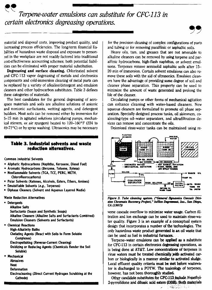
Circulating pumps or other forms of mechanical agitation can enhance cleaning with water-based cleaners. New aqueous cleaners are formulated to promote oil phase sep- aration. Specially designed process tanks, oil skimmers, co- alescing-type oil-water separators, and ultrafiltration de- vices can remove and concentrate the oils.
Deionized rinse-water tanks can be maintained using re-
Figure 3. Tu& cleaning @em. (Tenend L&"dcs cofiwir Diui- sia Chromate Recorroty w, " Infilco Daprrmant. Inc., Son Diego, c.4 (19el)) verse cascade overflow to minimize water usage. Carbon fil- tration and ion exchange can be used to maintain rinse-wa- ter quality. Figure 3 is an example of a conceptual system design that incorporates a number of the technologies. The only hazardous waste product generated is an oil waste that can be used as fuel in industrial
Terpene-water emulsions can for CFC-113 in certain electronics degmshg operations, as is being done at AT&T. Low concentratiolu of terpenes in rinse waters must be treated chemkal ly .~ activated car- bon or biologically in a manner s i m i i Q activated sludge. Local effluent quality criteria must be met before wastewa- ter is discharged to a POTW. The toxkology of terpenes, however, has not been thoroughly studied.
Othgr candidate substi WthYl- 2-pyklidone and dibas materials
Y
. -
Tabk 4. Cadidate substitutes for wlvents.
Existing Solvents Candidate Substitutes
Vapor Dogrearing TCE Water-Based/Alkallne Cleaners TCA Aeromarine: Aeroclean LT PERC CFC-113 815 QR, 815 CD
Hand-Wipe Surface Cleaning Low Vapor Pressure (< 20 mm Hg)
require further study for potential health hazards. Once ap- plied, they do not evaporate readily. They do not contain emulsifiers, and they cannot be rinsed with water. Both are fairly expensive specialty chemicals. These compounds, however, may be the best option for very specific applica- tions. For example, DBE is advertised as an excellent can- didate for cleaning microelectronic soldering fluxes that contain DBE analogs.
Table 4 lists some of the commercial formulations avail- able for aerospace cleaning applications. (This is not an en- dorsement of any commercial product, nor is the list com- prehensive.) Further development of alkaline cleaners and
terpene hydrocarbons can eliminate the use of chlorinated, CFC-based, and naphtha-based solvents in the aerospace in- dustry for degreasing, surface cleaning, and equipment maintenance. Case-by-case testing and development of cleaners are required to address the specifics of any given plant operation. A dramatic decrease in hazardous waste generation and the emission of air toxics and VOCs will result. Disposal costs can be greatly reduced, and the re- maining hazardous waste oils and hydrocarbons can be con- sumed in an environmentally safe manner either as supple- mental fuel for industrial furnaces or to fuel hazardous waste incinerator afterburners. Pilot testing and implemen- tation of solvent substitutes for metal cleaning are under- way at Boeing, McDonnell-Douglas, General Dynamics, Tinker Air Force Base, and several other United States Air Force facilities.
Surface finishing.' A major industrywide research effort is underway to remove chromium from metal surface finish- ing processes. Nonchromated etching and deoxidizing solu- tions consisting mainly of nitric, hydrofluoric, andlor sul- furic acids are being studied. Spent solutions from these processes could be neutralized and treated with ion ex- change, ultraviolet ozonation, or other ion removal and toxic organic compound destruction technologies. Process water can then be either discharged or recycled. Most impor- tantly, the amount of heavy metal sludges, which are banned from land disposal, will be greatly reduced.
Substitutes for chromic acid anodize are also being inves- tigated. Potential alternatives include sulfuric acid and phosphoric acid anodize. Sulfuric acid anodize appears to be the most promising substitute. The alternatives, how- ever, have not demonstrated the degree of protection pro- vided by chromic acid anodize.
Sulfuric acid anodize also creates concern about a poten- tial increase in metal fatigue. These harsher acids can make metal brittle or reduce aluminum tensile strength if improp erly applied, which for certain types of high-g-force aircraft would be critical defects. More detailed research is needed to determine the extent to which sulfuric acid anodize can be substituted for chromic acid. Benchscale research will take about one to two years, and developments for initial implementation an additional year or two.
Painting. The development of water-reducible primers for aircraft has decreased solvent usage and air emissions, pri- marily MEK and n-butyl acetate required when applying paint. The General Dynamics Fort Worth Division is the world's largest user of water-reducible aircraft primer. Water-reducible paint required manufacturers to develop barium chromate pigments to substitute for the more water- soluble strontium chromate pigments used in solventborne formulations.
One of the innovations in painting technology is the use
Chemical Engineering A.ogress
c s -
of I
PhY ni at use fov-
f0U
PlP Pt a - res bt' si! pai pro' bl the of tI
P, do tir fr
tia bl
SUI
sc te - the> Th g1 cell pe;, ir S; rec. tc - ti fac:
It e E. fol
__ ca
w
-
Pan
SF M L h
A
-
. J
1 1 7 3 3 I 7; 3
ent
will
ple-
fort
sul-
5 :to 3 7 F f I pri-
I e
=$
f” lross
of fine polymer beads delivered by high-pressure air to physically remove paint from the metal surface. This tech- nique, known as plastic media blasting, is being pioneered at U.S. Air Force aircraft maintenance facilities. After being used, the plastic beads are separated from the paint chips for reuse. The paint waste generally remains hazardous be- cause of the leachability of the heavy metals (Pb, Cd, Cr) found in many pigments. The plastic bead technique re- places the traditional methylene chloride (MECL) and phenol-based paint strippers. MECL is listed by the EPA as a suspected carcinogen. Its use may eventually be further restricted by the EPA and OSHA. Substitution of plastic bead blasting technology can eliminate hazardous air emis- sions and can greatly reduce the volume and toxicity of the paint waste solids. Another promising technology is a high- pressure sodium bicarbonate slurry spray. Plastic media blasting works only on flat and mildly curved surfaces, and there is some concern that bead blasting may cause fatigue of the metal surface.
Difficult-baccess areas will still require a liquid stripper. Paint companies are developing hgh-alkalinity strippers that do not contain MECL or phenol. By the mid-lWs, we es- timate that MECL stripping will be able to be eliminated from aerospace production and maintenance facilities. The use of chemical strippers can be reduced by 7540% ini- tially in most aircraft applications by substituting bead blasting.
Another method reducing the volume of paint waste re- sulted with the advent of detactifiers for waterfall paint spray booths. Here, a polymeric solution is added to the wa- ter in the paint booth. Upon contact with paint overspray, the polymer reacts with and encapsulates the paint particle. The paint granules can be separated from the water by gravity settling or, if continuous operation is desired, by centrifugation. The paint waste product has the general a p pearance of fine sand. Waste volume is reduced by eliminat- ing excess water. Handling, packaging, and disposal are simplified, and paint booth maintenance requirements are reduced. Because the encapsulated material has passed EP toxicity and TCLP tests, disposal options include incinera- tion and landfills at a permitted hazardous waste disposal facility.
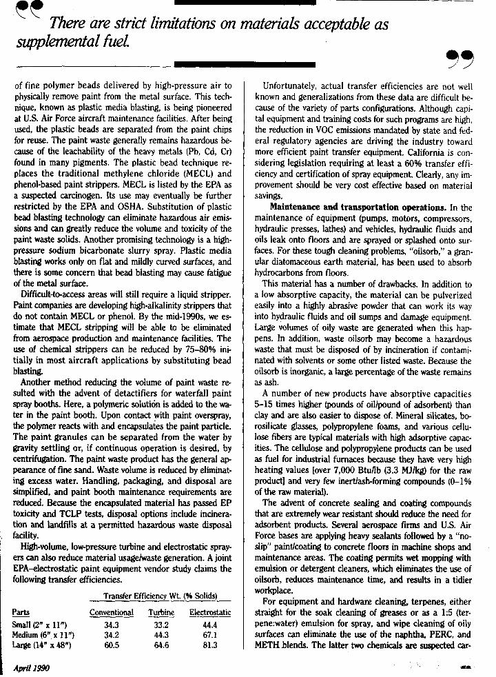
High-volume, lowpressure turbine and electrostatic spray- ers can also reduce material usagehvaste generation. A joint EPA-electrostatic paint equipment vendor study claims the following transfer efficiencies.
Transfer Efficiency Wt. (46 Solids)
- Parts Conventional Turbine Electrostatic
Medium (6” x 11”) 34.2 44.3 67.1 Large (14” x 48“) 60.5 tX.6 81.3
Small (2” x 11 ”) 34.3 33.2 44.4
I
There are strict limitations on materia& acceptable GS cc supplemental fuel.
99 Unfortunately, actual transfer efficiencies are not well
known and generalizations from these data are difficult be- cause of the variety of parts configurations. Although capi- tal equipment and training costs for such programs are high, the reduction in VOC emissions mandated by state and fed- eral regulatory agencies are driving the industry toward more efficient paint transfer equipment. California is con- sidering legislation requiring at least a 60% transfer effi- ciency and certification of spray equipment. Clearly, any im- provement should be very cost effective based on material savings.
Maintenance and transportation operations. In the maintenance of equipment (pumps, motors, compressors, hydraulic presses, lathes) and vehicles, hydraulic fluids and oils leak onto floors and are sprayed or splashed onto sur- faces. For these tough cleaning problems, “oilsorb,” a gran- ular diatomaceous earth material, has been used to absorb hydrocarbons from floors.
This material has a number of drawbacks. In addition to a low absorptive capacity, the material can be pulverized easily into a highly abrasive powder that can work its way into hydraulic fluids and oil sumps and damage equipment. Large volumes of oily waste are generated when this hap- pens. In addition, waste oilsorb may become a hazardous waste that must be disposed of by incineration if contami- nated with solvents or some other listed waste. Because the oilsorb is inorganic, a large percentage of the waste remains as ash.
A number of new products have absorptive capacities 5-15 times higher (pounds of oillpound of adsorbent) than clay and are also easier to dispose of. Mineral silicates, bo- rosilicate glasses, polypropylene foams, and various cellu- lose fibers are typical materials with high adsorptive capac- ities. The cellulose and polypropylene products can be used as fuel for industrial furnaces because they have very high heating values [over 7,000 Btufib (3.3 MJhg) for the raw product] and very few inertlash-forming compounds (0-1% of the raw material).
The advent of concrete sealing and coating compounds that are extremely wear resistant should reduce the need for adsorbent products. Several aerospace firms and U.S. Air Force bases are applying heavy sealants followed by a “no- slip” paintfcoating to concrete floors in machine shops and maintenance areas. The coating permits wet mopping with emulsion or detergent cleaners, which eliminates the use of oilsorb, reduces maintenance time, and results in a tidier workplace.
For equipment and hardware cleaning, terpenes, either straight for the soak cleaning of greases or as a 1:5 (ter- pene:water) emulsion for spray, and wipe cleaning of oily surfaces can eliminate the use of the naphtha, PERC, and METHblends. The latter two chemicals are suspected car-
H
*
~~
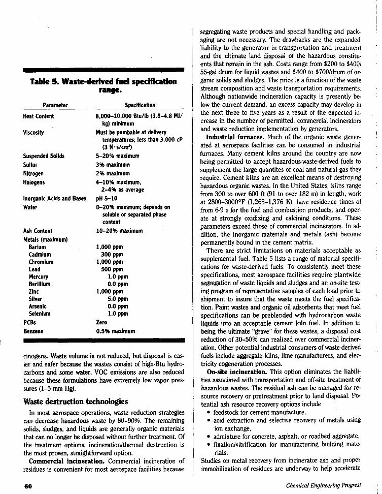
Table 5. Waste-detived fuel spectficatlon
Parameter
range.
Swcification
Heat Content
viscosity
Suspended Solids Sulfur Nitrogen Halogens
Inorganic Acids and Bases Water
Ash Content Metals (maximum)
Barium Cadmium Chromium lead Mercury Berillium Zinc Silver Arsenic Selenium
PCBs Benzene
8,OOO-10,OOO BtU/lb (3.8-4.8 MJ/ kg) minimum
temperatures; less than 3,000 CP (3 N*s/cm’)
5-20% maximum 3% maximum 2% maximum 610% maximum,
pH 5-10 0-20% maximum; depends on
soluble or separated phase content
Must be pumbable at delivery
2-4% as average
10-20% maximum
Lo00 ppm 300 PPm
1,OOO PPm 500 Ppm
1,OOO Ppm
1.0 ppm 0.0 ppm
5.0 ppm 0.0 ppm 1.0 ppm
zero 0.5% maximum
cinogens. Waste volume is not reduced, but disposal is eas- ier and safer because the wastes consist of high-Btu hydro- carbons and some water. VOC emissions are also reduced because these formulations have extremely low vapor pres- sures (1-5 mm Hg).
Waste destruction technologies In most aerospace operations, waste reduction strategies
can decrease hazardous waste by 8040%. The remaining solids, sludges, and liquids are generally organic materials that can no longer be disposed without further treatment. Of the treatment options, incinerationlthermal destruction is the most proven, straightforward option.
Commercial incineration. Commercial incineration of residues is convenient for most aerospace facilities because
6Q
segregating waste products and special handling and pack- aging are not necessary. The drawbacks are the expanded liability to the generator in transportation and treatment and the ultimate land disposal of the hazardous constitu- ents that remain in the ash. Costs range from $200 to $4001 55-gal drum for liquid wastes and $400 to $700/drum of or- ganic solids and sludges. The price is a function of the waste stream composition and waste transportation requirements. Although nationwide incineration capacity is presently be- low the current demand, an excess capacity may develop in the next three to five years as a result of the expected in- crease in the number of permitted, commercial incinerators and waste reduction implementation by generators.
industrial furnaces. Much of the organic waste gener- ated at aerospace facilities can be consumed in industrial furnaces. Many cement kilns around the country are now being permitted to accept hazardous-wastederived fuels to supplement the large quantites of coal and natural gas they require. Cement kilns are an excellent means of destroying hazardous organic wastes. In the United States, kilns range from 300 to over 600 ft (91 to over 182 m) in length, work at 2800-3000°F (1,265-1,376 K), have residence times of from 6 9 s for the fuel and combustion products, and oper- ate at strongly oxidizing and calcining conditions. These parameters exceed those of commercial incinerators. In ad- dition, the inorganic materials and metals (ash) become permanently bound in the cement matrix.
There are strict limitations on materials acceptable as supplemental fuel. Table 5 lists a range of material specifi- cations for wastederived fuels. To consistently meet these specifications, most aerospace facilities require plantwide segregation of waste liquids and sludges and an on-site test- ing program of representative samples of each load prior to shipment to insure that the waste meets the fuel specifica- tion. Paint wastes and organic oil adsorbents that meet fuel specifications can be preblended with hydrocarbon waste liquids into an acceptable cement kiln fuel. In addition to being the ultimate “grave” for these wastes, a disposal cost reduction of 30-50% can realized over commercial inciner- ation. Other potential industrial consumers of wastederived fuels include aggregate kilns, lime manufacturers, and elec- tricity cogeneration processes.
On-site incineration. This option eliminates the liabili- ties associated with transportation and off-site treatment of hazardous wastes. The residual ash can be managed for re- source recovery or pretreatment prior to land disposal. PO- tential ash resource recovery options include
feedstock for cement manufacture, acid extraction and selective recovery of metals using
admixture for concrete, asphalt, or roadbed aggregate, fixationlvitrification for manufacturing building mate-
Studies on metal recovery from incinerator ash and proper immobilization of residues are underway to help accelerate
ion exchange,
rials.
Chemical Engineering prosress
\ \ Many cement kilns are now being permitted to accept hazardous-waste-dmved fuels to supplement the large quantities of coal and naturalgas they require.
the development of these options. For most large facilities, rotary kilns are the incineration
technology of choice because they can accommodate the feed and combustion requirements for the spectrum of liq- uid, sludge, and solid wastes generated at most large aero- space facilities in continually varying proportions.
In conclusion Many reduction alternatives exist in the aerospace indus-
try, but the complexity of aircraft operating parameters and the need for high-technology materials and processes make the changes needed to achieve waste reduction difficult to implement.
The following, however, are conclusions that many who are active in waste reduction in the aerospace industry would agree on.
1. The elimination of nearly all forms of land disposal can be realized; several facilities have already achieved this milestone.
2. Zero discharge (defined as no manifested hazardous waste being shipped from a facility) is an achieveable goal.
3. Aerospace has a sufficient number of highly qualified material and chemical process engineers to generate waste minimization solutions, if properly focused by management.
4. Waste minimization solutions are generally extremely cost effective by both traditional and risk-management ac- counting methodologies.
5. Effective waste minimization in a company requires top management commitment, resource allocation, and a goal- oriented program approach.
6. Waste minimization planning must be based on sound analysis of the processes that generate the waste, not on ar- tifically generated or mandated external goals.
7. Improved housekeeping and maintenance practices are the first step in waste reduction.
8. Material producers and vendors should be encouraged to work with manufacturers in recycling waste productslex- cess materials.
9. Changes in raw material can contribute significantly to waste reduction and atmospheric emissions; a principal area is the substitution of water-based cleaners and lowvolatility organics for CFC-113 and chlorinated solvents.
10. Process changes can contribute significantly to waste and hazard reduction; examples are aluminum ion vapor deposition substitution for cyanide-containing cadmium plating, machine coolant recovery, hydraulic oil recycling, and electrodialysis of process baths.
11. Segregation of metallic and organic wastes is the key to effective recycling or resource recovery.
12. The use of chromium can be greatly reduced, but
33 probably not eliminated entirely, from metal finishing pro- cesses.
13. Air emissions legislation, especially in ozone nonat- tainment areas, will require large amounts of resources in order to develop reduction strategies to control the rela- tively small amount of VOCs generated in surface-coating operations. .
14. Incineration will play a role in waste reduction strate- gies and in eliminating land disposal requirements.
15. Future product lines will rely more upon polymeric and composite materials and less upon metals for structural components, Although this will greatly decrease the liquid and solid wiastes that are generated, it will increase con- cerns over worker health and safety when exposed to these less well understood chemicals and their by-products; this will require :increased air quality monitoring and the use of air emission control equipment for the relatively small amounts offair emissions generated by the curing and py- rolysis of camposites.
16. The dtimate success of any waste reduction program depends upon effective and continuous employee support.
d
Recommendbd reading
c
“Serious Reduction of Hazardous Waste,” Summary, OTA-ITE 318, CongreJJ of the United States, Office of Technology Assessment, Washing- ton DC (SeptdW). This excellent brochure was among the first to ad- dress industrial pollution prevention by improved process and production efficiency. Thg political, management, and public policy issues to achieve effective source reduction are outlined and discussed. Specific industry case studies are givgn as examples. “The EPA Manual for Waste Minimization Opportunity Assess- ments,” EPA&0012-8&025, W%hington, DC (Apr. 1988). This manual is a stepby-step guideline for plannmg, organizing, and conducting an effec- tive means of lpducing the generation of hazardous waste at the source. A series of work sheets are provided to help quantify the rati of technical options, including waste stream characterization, techrid feasibility, prof- itability, and p‘ayback period. “Electronics $leani& Degreasiog, and Dry Cleaning !!$ohrents Tech- nical Options Report,” United Nations Environment Program, New York (June 1989). This report discuses the use of CFc113, one of the five CKs principally responsible for stratospheric ozone destruction, and the feasi- bility of replacing it with alternative cleaning agents or processes that will reduce or eliminate the need for CFC113. “Alternative Tefhwlogy for Recycling and Treatment of Hazardous Waste,” Department of Health Services, State of Califprnia, .Sacramento, CA (July 1986). A simplifd outline of opt~ons for eluninatmg land dis posal of wastes once they have been generated.is given. This is a good first reference for those new to waste management issues.


![Comparison of “CO Efficiency” between Company and Industryinfohouse.p2ric.org/ref/37/36369.pdf · Efficiency” between Company and Industry Kiyotaka TAHARA ... [yen/ kg-CO2]](https://static.documents.pub/doc/80x56/5ab70b477f8b9a6e1c8e6a03/comparison-of-co-efficiency-between-company-and-industryinfohousep2ricorgref3736369pdfefficiency.jpg)


