82
1 Heat Engineering Solved Problems By Dr. P. Raveendiran Asst. Professor, Mechanical

1
Heat Engineering Solved Problems
By Dr. P. Raveendiran
Asst. Professor, Mechanical

2
UNIT - 1 Reciprocating compressor
1.A single stage reciprocating compressor takes 1m3 of air per minute at 1.013 bar and
15oC and delivers it at 7 bar. Assuming that the law of compression is Pv1.35= constant, and
the clearance is negligible, calculate the indicated power?
Solution
Volume of air taken in,V1 = 1 m3/ min
Intake pressure, p1 = 1.013 bar
Initial temperature, T1 = 15 + 273 = 288 K
Delivery pressure, P2 = 7 bar
Law of compression: PV1.35 = constant
Indicated power I.P.:
Mass of air delivered per min.,
min/266.1288287
110013.1 5
1
11 kgRT
vpm
Delivery temperature, /n)(n
ppTT
1
12 12
= K2.475013.17288
35.1/)135.1(
Indicated work = min/)( kJTTmR1n
n12
= min/.(...
. kJ2542882475287022611351
351
i.e., Indicated power I.P = ).(23.460254 AnskW

3
2.An air compressor cylinder has 150mm bore and 150mm stroke and the clearance is
15%. It operates between 1 bar, 27oC and 5 bar. Take polytrophic exponent n=1.3 for
compression and expansion processes find?
i. Cylinder volume at the various salient points of in cycle.
ii. Flow rate in m3/min at 720 rpm and .
iii. The deal volumetric efficiency.
Given
D = 15010-3m P2 = 5105 N/m2
L = 15010-3 m T1 = 27+273 = 300K
Vc =0.15Vs N = 720rpm
P1 = 1105 N/m2 pvn = C n=1.3
Find
i. V1, V2, V3, V4
ii. FAD (Va)
iii. v
Solution
V1 = Vc + Vs
Vs = min/9085.172015.0.)15.0(4
.4
322 mNLD
Vc = 0.15 Vs
=0.151.9085
Vc= 0.2862 m3/min
V1 = Vc + Vs
= 0.2862 + 1.9085
m3/min
n
22n
11 VPVP
V2 = V1
n
PP
1
2
1
V1 = 2.1948

4
= 2.19483.1
1
5
5
105101
= Vc
Vc = V3 n
44n
33 VPVP
V4 = V3
41
4
3
PP
WKT
P2 = P3
P1 = P4
V4 = V3n1
1
2
PP
= 0.28623.1
1
5
5
101105
Volumetric efficiency (v) = 1+k-k n
PP
/1
1
2
k= Clearance Raito =9085.12862.0
s
c
VV
v = 1+0.1499 – 0.14993.1
1
15
v = 0.633 = 63.3%
V2 = 0.6366 m3/min
V3= 0.2862 m3/min
V4 = 0.98674 m3/min
K =0.1499
v = 63.3%
5
WKT
v = sV
FAD
FAD = v Vs
=0.6331.9085
3.Calcute the diameter and stroke for a double acting single stage reciprocating air
compressor of 50kW having induction pressure 100 kN/m2 and temperature 150oC. The
law of compression is PV1.2 = C and delivery pressure is 500 kN/ m2. The revolution/sec
=1.5 and mean piston speed in 150 m/min. Clearance is neglected.
Given:
Double acting single stage
Compressor
IP = 50kW
P1 = 100103 N/m2
T1 = 15 + 273 = 288K
PV1.2 = C n=1.2
P2 = 500103 N/m2
N = 1.5 rps = 1.560 rpm
2LN = 150m/min (Double acting )
Find
i. D and L
Solution
For double acting compressor average piston speed = 2LN
2LN = 150 m/min
L= m833060512
150 ..
FAD = 1.2083 m3/min 3
L = 0.833 m
6
To Find D
IP = W.Nw
where
Nw = Number of working stroke
For Double acting Nw = 2N
For single acting Nw = N
Nw = 21.560 = 180 rpm
W.D/cycle =
11
1
1
211
nn
ppVp
nn
=
833.0
410100
12.12.1 23 D
1
100500 2.1
2.0
N-m
IP = 60. wNW
50103 = 60
180D1207642 2
D2 = 0.1380
4.A single acting reciprocating air compressor has cylinder diameter and stroke of 200 mm
and 300 mm respectively. The compressor sucks air at 1 bar and 27oC and delivers at 8 bar
while running at 100 r.p.m Find: 1. Indicated power of the compressor; 2. Mass of air
delivered by the compressor per minute; and 3. temperature of the delivered by the
compressor. The compression follows the law PV1.25 = C Take R as 287 J/kg K.
Solution.
Given
D=200 mm = 0.2m;
L = 300 mm = 0.3m;
W= 120764.2D2
D=0.371 m

7
p1= 1 bar = 1105 N/m2;
T1 = 27oC = 27 + 273 = 300K;
p2 = 8 bar;
N = 100 r.p.m
n=1.25;
R= 287 J/kg K
1.Indicated power of the compressor
321 m00940LD
4V .
We know that workdone by the compressor for polytropic compression of air as
W =
11
1
1
211
nn
ppVp
nn
= mN
1
180094.0101
125.125.1 125.1
25.1
5
=4700(1.516-1) = 2425 N-m
Since the compressor is single acting, therefore number of working strokes per
minute,
Nw = N = 100
Indicated power of the compressor
=60
100242560
NW w = 4042kW
2.Mass of air delivered by the compressor per minute
Let m= Mass of air delivered by the compressor per
stroke.
We know that P1V1 = mRT1
kg01090300287
00940101VPm5
11 ..RT1
per stroke
and mass delivered minute =mNw= 0.0109100 = 1.09kg

8
3. Temperature of air delivery by the compressor
Let T2= Temperature of air delivered by the compressor.
We know that 5161818
pp
TT 20251
1251n
1n
1
2
1
2 ....
T2 = 1.516T1 = 1.516300 = 454.8K = 181.8oK
5.A single –stage double –acting air compressor is required to deliver 14 m3 of air per
minute measured at 1.013 bar and 150oC. The delivery pressure is 7 bar and the speed 300
r.p.m. Take the clearance volume as 5% of the swept volume with the compression and
expansion index of = 1.3 Calculate:
i. Swept volume of the cylinder;
ii. The delivery temperature;
iii. Indicated power.
Solution
Quantity of air to be delivered = 14 m3/min
Intake pressure and temperature p1 = 1.0.13 bar,
T1 = 15 + 273 = 288 K
Delivery pressure p2 = 7 bar
Compressor speed, N = 300 r.p.m
Clearance volume, Vc = 0.05 Vs
Compression and expansion index n=1.3
Swept volume of the cylinder, Vs:
Swept volume Vs = V1 – V3 = V1 – Vc = V1 -0.05 Vs
V1-V4 = wN
FAD
and V1 – V4 = 2300
14
= 0.0233 m3
Now, V1 = 1.05 V8 and 3
4
VV = 423.4
013.17 3.1
11
1
2
n
pp
i.e., V1 – V3 = 4.423 V3 = 4.423 0.05 Vs = 0.221 Vs
(V1 – V4) = 1.05 Vs -0.221 Vs = 0.221 Vs

9
3
8 0281.0221.005.1
0233.0 mV
i.e Swept volume of the cylinder = 0.0281 m3 .
ii. The delivery temperature, T2
Using the relation n
n
pp
TT
1
1
2
1
2
T2 = T1 n
n
pp
1
1
2
= 288 K450
01317 31
131
.
.
.
Delivery temperature = 450 – 273 = 177oC
iii Indicated power:
Indicated power
1)(1
1
1
2411
nn
pPVVp
nn
=
101317
61014100131
13131 31
131
3
5 ..
..
..
= 57.56 kW
Indicated power = 57.56 kW
6. A single stage single acting air compressor delivers 0.6 kg of air per minute at 6 bar .
The temperature and pressure at the end of suction stroke are 30oC and 1 bar. The bore
and stroke of the compressor are 100 mm and 150 mm respectively. The clearance is 3% of
the swept volume Assuming the index of compression and expansion to be 1.3. find:
i. Volumetric efficiency of the compressor
ii. Power required if the mechanical efficiency is 85%, and
iii. Speed of the compressor (r.p.m)
Given
Mass of air delivered, m=0.6kg/min
Delivery Pressure, p2 =6 bar
Induction Pressure, p1 =6 bar

10
Induction temperature, T1 = 30 + 273 = 303 K
Bore, D= 100mm = 0.1m
Stroke length , L=150mm = 0.15 m
Clearance volume, Vc = 0.03 Vs
Mechanical efficiency mech =85%
i. Volumetric efficiency of the compressor,vol:
vol =1+ k - kn
pP
1
1
2
Where k = 030VV
s
c .
vol = 1 + 0.03 – 0.03 %096.9191096.016 3.1
1
or
ii. Power required if the mechanical efficiency is 85%, and
Indicated power =
11
1
1
21
nn
pPmRT
nn
kW93.1116303287.0
606.0
13.13.1 3.1
13.1
Power required to drive the compressor: kWmech
27.285.093.193.1
iii. Speed of the compressor (r.p.m)
Free air delivery, F.A.D = 51
1
1013031000287.06.0
p
mRT = 0.5218 m3/min
Displacement volume /minm..... 35728091096052180DAF
vol
Also 0.5728=4 D2L N (for single – acting compressor)
or 0.5728=4 0.120.15 N

11
Speed of compressor N=15.01.0
45728.02
= 486.2 r.p.m
7.A single stage , single air compressor running at 1000 r.p.m delivers air at 25 bar . For
this purpose the induction and free air conditions can be taken as 1.013 bar and 150oC and
the free air delivery as 0.25 m3/min. The clearance volume is 3% of the swept volume and
the stroke bore ratio is 1:2:1 Take the index of compression and expansion as 1.3. calculate
also the indicated power and the isothermal efficiency
Given data:-
With clearance volume
Single stage single acting air compressor
N=1000 rpm
p2= 25 bar = 25105 N/m2
T1 = 15o = 273+15 =288K
Vc = 0.03Vs
03.0 kVV
s
c
21
)()(
LBoreDStroke
n = 1.3
PVn = C (polytropic process) To find
i. v , D and L
ii. (I.P) and Iso
i. v=1+ k - kn
pP
1
1
2
v = 1+0.03-0.03 3.11
5
5
10013.11025
v = 0.6766
L = 2D

12
ii. IP =60
NWpoly
Inductor power =I.P
n
n
pPVVp
nnWpoly
1
1
241 )(
1
v = S
a
VVFAD /
Vs = 6766.0
25.0
v
aV
Vs = 0.369 m3/min
Vs = 4 D2L
0.369 = 4 D22D =
2D3
D =0.617 m = 617 mm
L = 2D = 2 0.617
L = 1234 mm
Vc = 0.011 m3/min = V3
V1 = Vc + Vs
V1 = 0.011 + 0.369
3-4 is expansion
pvn =C
n
4
3
3
4
vv
PP
n1
1
2
1
4
3
3
4
PP
PP
vv

13
V4 = V3 1
1
2
PP
V4 = 0.129 m3/min
n
n
pPVVp
nnWpoly
1
1
241 )(
1
=
1
013.15.2)129.038.0(10013.1
3.03.1 3.1
3.0
5
W.D poly = 120713.193N-min
I.P = 60
. NDpolyW
I.P = 60
100012713
iso = poly
iso
WW
Wiso
1
2211 ln)(
ppVVp
iso
1)(1
ln)(
1
1
2411
1
2211
ppVVp
nn
ppVVp
iso = 19.120713
013.125ln)129.00380.0(10013.1 5
iso = 0.675
iso = 67.5%

14
8.A two stage air compressor air from 1 bar and 20oC to 42 bar. If the law of compression
is pv1.35 = constant and the intercooling is complete to 20oC, find per kg of air:1. The work
done is compressing; and 2. The mass of water necessary for abstracting the heat in the
intercooler, if the temperature rise of the cooling water is 250oC
p1= 1 bar = 1105 N/m2
T1 = 20o C= 20+273 =293K
p3= 42 bar = 42105 N/m2
n=1.35
T3 = 20o C= 20+273 =293K; m= l kg;
Rise in temperature of cooling water =25o C;
R=287J/kg K cp= 1 kJ /kg K
we know that for complete intercooling. the intercooler pressure
p2= bar486421pp 31 .
and volume of air admitted for compression
V1 kgmp
mRT /84.0101
2932871 35
1
1
of air
1. Work done compressing the air
21
1
1
2
1
1
211
nn
nn
pP
pPp
nnW
= mN
248.6
42148.684.0101
135.135.1 35.1
135.135.1
135.1
5
=3.24105 (1.62 +1.62 -2) = 4.017105 N-m
2.Mass of water necessary for abstracting the heat in the intercooler.
Let mw= Mass of water necessary /kg of air ,and
T2 = Temperature of the air entering the intercooler.
622.1148.6 35.1
135.11
1
2
1
2
n
n
PP
TT
15
T2 = T11.622 = 293 1.622 = 475.6 K
We know that heat gained by water
= Heat lost by air
mwcwRise in temperature
= mcp(T2-T3)
mw4.2 25 =11(475.6-293) =182.6
mw = 1.74kg
9.A two- stage acting reciprocating compressor takes in air at the rate of 0.2 m3/s. The
intake pressure and temperature of air 0.1MPa and 16oC. The air is compressed to a final
pressure of .7Mpa. The intermediate pressure is ideal and intercooling is perfect. The
compression index in both the stages is 1.25 and the compressor runs at 600 r.p.m.
Neglecting clearance determine:
i. The intermediate pressure
ii. The total volume of each cylinder,
iii. The power required to drive the compressor and
iv. The rate of heat rejection in the intercooler.
Take cp= 1.005 kJ/kg K and R =0.287 kJ/kg K
Solution .
Intake volume V1=0.2 m3/s
Intake pressure p1 = 0.1MPa,
Intake temperature T1 = 16 + 273 = 289 K
Final pressure p3 =0.7MPa
Compression index in both stages, n1 = n2 n =1.25
Speed of the compressor N = 600 r.p.m
cp = 1.005kJ/kg K; R = 0.287 kJ/kg K
i. The power required to drive the compressor,P2:
p2= a31 MP264607010pp ...
ii. The total volume of each cylinder ,Vs1,Vs2:
We know that Vs1 160VN or Vs1 2.0
60600

16
Vs1 (Volume of L.P cylinder) = 302.060
2.0600 m (Ans).
Also 2s11s1 VpVp or 2
1s12s p
VpV
VS2 (Volume of H.P. Cylinder) = 3m00756026460
02010 ..
.. (Ans)
iii. The rate of heat rejection in the intercooler:
Mass of air handled, skg24102892870
201010RT
Vpm3
1
11 /..
.).(
Also, n
1n
1
2
1
2
pp
TT
or
2511251
2
1026460
289T .
.
..
or T2=351.1K
Heat rejected in the intercooler = m cp(T2-T1)
= 0.2411.005 (351.1-289) = 15.04 kJ/s or 15.04 kW.(Ans)
10. A single acting reciprocating air compressor has a swept volume of 2000 cm3 and
runs at 800 rpm. It operates with pressure ratio of 8 and clearance of 5% of the
swept volume. Inlet pressure and temperature are 1.013 bar, and 15oC respectively.
Assume n=1.25 for both compression and expansion. Find
i. Indicated power
ii. Volumetric efficiency
iii. Mass flow rate
iv. FAD
v. Isothermal efficiency
vi. Actual Power required to drive the compressor if mech=85%
Given
Single acting reciprocating compressor
Vs = 2000 cm3 = 0.002 m3
N = 800 rpm
8PP
PP
4
3
1
2

17
Vc = 5% Vs
= 0.050.002
Vc = 0.0001 m3
p1 = 1.013105 N/m2
T1 = 15+273 = 288 K
PVn
= C n = 1.25
Find: i)IP ii)v iii)m iv) FAD(Va) v) iso vi) Pact if m=85%
Solution
WKT
Clearance ratio (k) = 002000010
VV
s
c
..
k = 0.05
Volumetric efficiency (v) = 1+k- k n1
1
2
PP
= 1+0.05 – 0.05 (8)1/1.25
v = 78.61%
WKT
v = sV
FAD
FAD = sv V
= 0.78610.002
= 1.572210-3 m3
SpeedStrokeFAD
minFAD
= 1.572210-3800
FAD = 1.2578 m3/min
To find mass flow rate
Pv = mRT
18
m = 288287
25781100131RTpV 5
..
m = 1.542 kg/min
To find – Indicated power
IP = sec
. NDW
Nw = N (single acting) = 800 rpm.
W.D = )( 12 TTmR1n
n
kJ/min.
T2 = n
1n
1
21 P
PT
= 2511251
8288 ..
)(
T2 = 436.53 K
W.D = 28805343628705421250251
.(....
W.D = 328.66 kJ/min
IP = 60
66328sDW ..
IP = 5.48 kW
To find isothermal efficiency
isoW =
1
211 P
PVP ln
= mRT1 ln
1
2
PP
= 1.5420.287288ln (8)
(W.D)iso = 265.04 kJ/min
iso = act
iso
DWDW
).().(
Actual work= mech (W.D)theoretical
= 0.85328.66

19
(W.D)act = 279.361 kJ/min
iso = 10036127904265
..
iso = 94.87%
11. An air compressor takes in air at 1 bar and 20oC and compresses it according to law
pv1.2=constant. It is then delivered to a receiver at a constant pressure of 10 bar.
R=0.287 kJ/kg K. Determine
(i) Temperature at the end of compression
(ii) Workdone and heat transferred during compression per kg of air.
Solution
T1=20+273=293 K; P1=1 bar; P2=10 bar
Law of compression : pv1.2=C; R=287 J/kgK
(i) Temperature at the end of compression T2
For compression process 1-2, we have
46811
10PP
TT 21
121n
1n
1
2
1
2 ..
.
T2=T11.468 = 2931.468 = 430 K or 157oC
(ii) Workdone and heat transferred during compression per kg of air:
Workdone, W= mRT1
1PP
1nn n
1n
1
2
= 10.287293 ofairkgkJ1323611
10121
21 21121
/..
. ..
Heat transferred during compression,
UWQ
=
1nRcTTTTc
1nvpvp
v1212v2211 )()(
= (430-293) 2398121
28707180 ....
kJ/kg
Negative sign indicates heat rejection.

20
UNIT – II
1. The cylinder of a non-condensing steam engine is supplied with steam at a pressure
of 12 bar. The clearance volume is 1/10 of the stroke volume and the cut-off takes
place at 0.25 of the stroke. The back pressure is 1.1 bar. Find the mean effective
pressure of the steam on the piston. Assume hyperbolic expansion.
Solution
Given: p1=12 bar; k=vc/vs=1/10=0.1; M=(v2-vc)/vs=0.25; Pb=1.1bar
We know that mean effective pressure,
b11 PMk1kMKpMp
ln)(
=120.25+12(0.1+0.25) ln 1125010110 ...
.
= 6.7 bar Ans.
2. Estimate the brake power of simple steam engine having 250 mm piston diameter
and 40mm piston rod diameter with 250mm stroke length operating at 300 rpm.
The initial and back pressure of steam is 8.5 bar and 1.2 bar. Assume 90%
mechanical efficiency. Cut-off at 25% of forward stroke neglect clearance.
Given
D = 25010-3m p1 = 8.5 bar
L = 25010-3m pb = 1.2 bar
d = 4010-3m m = 90%
N = 300 rpm V2 = 0.25 Vs
Find
B.P
21
Solution
mIPBP
BP = mIP
IP = 60
10060
100 2211 wmwm NLApNLAp
Nw= N (assume single acting)
pm1 = pm2
= )(r11rp
n1 - pb
r = expansion ratio =2
3
VV
WKT
3
2
VV =0.25
2
3
VV = 4
25.01
r = 4
pm = pm 2141458 .)ln(.
pm = 3.871 bar
A1= 25.044
2 D
A1=0.196 m2
A2 = Area of Piston rod
= A1 - 2
4d
=0.196 - 2)04.0(4
A2 = 0.195 m2
IP = 60
100 21 AALNpm

22
= 60
0195196.030025.087.3100
IP = 189.195 KW
Bp = m IP
= 0.9189.195
BP = 170.28 KW
3 A compound engine is to develop 90 kW at 100 r.p.m. Steam is supplied at 7.5 bar and the
condenser pressure is 0.21 bar. Assuming hyperbolic expansion and expansion ratio of 15,
a diagram factor of 0.72 neglecting clearance and losses determine the diameters of the
cylinder so that they may develop equal powers. Stroke of each Stroke of each piston = LP
cylinder diameter.
Solution.
Power to be developed, I.P =90kW
Engine speed, N=100 r.p.m
Admission steam pressure, p1 = 7.5 bar
Condenser pressure pb =0.21 bar
Expansion ratio, r = 15
Diagram factor D.F.=0.72
Cylinder diameters, D L,p DH.p:
Stroke of each piston = L.P cylinder diameter
Pm(actual)referred to L.P. cylinder
= D.F b
1
pr1rp
)ln((
= 0.72
210151
1557 .)ln(.
= 1.18 bar
Indicated power,
IP= 60
100D4
D181100
3LANactualp10 PL
2PL
m
...)(
90 = 308.92D3L.p

23
DL.p = mmm 6636629.092.308
90 31
i.e Diameter of low pressure cylinder = 663 mm
Work dine in H.P. cylinder
=p1V1 + p1 V1 ln 221
2 VpVV
But p1V1 = 22Vp
Work dine in H.P. cylinder = p1 V1 ln (r) H.P 1
2r
VVPL
Work done in L.P cylinder = p2 V2+ p2 V2 ln2
3
VV - pb V3
= p2 V2+ p2 V2 ln(r) L.P- pb V3 2
3r
VVPL
Equating work done in H.P. cylinder to that done in L.P cylinder
p1V1 ln(r) H.P = p2 V2 ln(r) L.P- pb V3
ln
HP
LP
rr 1
11
3 VpVpb
But 2
3
VV = r=5
loge
pHPL
r
r
.. 115
5.721.0
Also PLr . =2
3
VV and pHr . =
1
2
VV and
VVr
VVr
1
2HP
2
3PL and.
ln
pHPL
r
r
.. ln
2
1
2
3
VV
VV ln 2
2
1215VV
ln
2
2
1215VV
1155.721.0

24
ln 215 1
22
VV
1 58.0155.721.0
215 1
22
VV 1.786, 7926
VV
21
22 .
Ratio of expansion for H.P cylinder, pHr . = 176.5)79.26( 21
1
2 VV
Also 2
3
VV =
1
3
VV
2
1
VV =
12 /15
vv=
176.515 =2.9
Volume of H.P cylinder = 663.04
663.09.2
663.04
.2 PHD
Diameter of H.P cylinder = 389 mm.
4. A single cylinder double acting steam engine has piton diameter 250mm stroke 400 mm
and diameter of piton and 50mm. The mean effective pressure on both side of the piton is
2.5 bar determine the Indicated power when the engine minis of 200 r.p.m .
Single cylinder double acting steam engine
D = 250 10-3m
L = 400 10-3m
d = 50 10-3m
pm1 = pm2 = 2.5 bar
N = 200 rpm
Find
i) IP
Solution
IP = 60
10060
100 2211 NLApNLAp mm
1mp = 2mp
IP = 60
100 21 AALNpm
A1 2
4D =
4 (0.25)2
A1 = 0.049 m2

25
221 050
40490d
4A ).(.
A2 = 0.047 m2
IP = 60
014.0049.02004.05.2100
IP = 32 kW
5. A single cylinder, double acting non- condensing steam engine 200 mm in diameter and
400 mm in stroke develops 30 kW at 100 r.p.m. The clearance is 10% and cut-off is 40% of
stroke. The pressure at the point of cut-off is 5 bar. The compression starts at 80% of the
stroke during return stroke. The pressure of the steam on compression curve at 90% of the
return stroke is 1.5 bar steam is dry saturated.
Calculate the actual and minimum theoretical possible specific steam consumption on I.P
basis. Take the missing quantity of cut-off as0.0072 kg/stroke.
Solution.
Diameter of engine cylinder, D = 200 mm = 0.2m
Length of stroke, L = 400 mm = 0.4m
Indicated power developed, I.P = 30kW
Engine speed, N = 100 r.p.m
Clearance volume Vc = 0.14 Vs
Cut off =0.4 Vs
Pressure at the point of cut –off, P1 = 5 bar
Steam pressure on compression curve at 90% of the return stroke,
P1 = 1.5 bar
Missing quantity at cut-off = 0.0072kg/stroke
Stroke volume Vs = 2
4D L =
4 0.22 0.4 = 0.01256 m3
Vs – Vc + (1-09) Vs = 0.1 Vs+0.1 Vs = 0.2 Vs
=0.2 0.01256 = 0.002512 m3
26
Mass of cushion steam/stroke
mc = 5
6
5
5
gVV
VV
= 159.1
002512.0 = 0.002167 kg/stroke
V1 – Vc + 0.4Vs = 0.1 Vs+0.4Vs = 0.5 Vs
= 0.5 0.01256 = 0.00628 m3
Mass of steam at point of cut –off if it is dry and saturated,
m1 = /kg0.375mbar 5at steam of volumespecificuuV 3
g1g1
1
375.0
00628.0 = 0.01674 kg/stroke
If ms is the mass of steam supplied/stroke the missing quantity is given by
(mc +ms) = missing quantity
0.002167 + m3-0.01674 = 0.0072
m3 = 0.02177 kg/stroke
Mass of steam supplied per hour = 0.02177 60 100 2 = 261.24 kg/h
Specific steam consumption on I.P basis
= 30
24.261 = 8.708 kg/kWh
Theoretical minimum possible steam/stroke will be if the steam at cut- off is dry and
saturated Thus , minimum possible steam supplied/stroke.
= m1-mc = 0.1674 – 0.002167 = 0.01457 kg/stroke
Minimum steam that may be supplied/hour
= 0.01457 60 100 2= 174.84kg/k
Hence, minimum specific steam consumption on I.P. basis
30
84.174 = 5.828 kg/kWh

27
6. The cylinder of a non – condensing steam engine is supplied with steam at 11.5 bar.
The clearance volume is 101 th of the stroke volume and the cut –off takes place at
41 th of
the stroke. If the pressure the end of compression is 5.4 bar compute the value of mean
effective pressure of the steam on he piston. Assume that expansion and compression are
hyperbolic. The back pressure is 1.1 bar.
Solution.
Admission pressure, p1 = 11.5 bar
Clearance volume Vc= svolumeVthofstroke101
Cut –off = thofstroke41
Pressure at the end of compression p5 = 5.4 bar
Back pressure pb = p3 = 1.1 bar.
Mean effective pressure ,pm:
The theoretical mean effective pressure, when clearance and compression are
considered is given by
Pm(th) = p1
ccaacap
cc
rc
r ebr
e log)()1(1log111
r = 1.010/4114
4/11
s
s
VVandc
ror
To find a (ratio of volume between points of compression and admission to the swept
volume Vs applying hyperbolic law between the point of beginning and end of compression:
p4V4 = p5V5 Vs = Vc and p4=pb = 1.1 bar and
1.1( Vc + a Vs)=5.4 Vc a = s
4
VcVV
a=s
cc
V1.1V1.1V4.5 V4 = Vc+ aVs
= s
cc
V1.1V1.1V4.5 =0.39 Also
101
VsVc

28
Vs = 10Vc
Now inserting various values in equation (i) we get
Pm(th) = 11.5
4/11.0
11.0log414.0
41
e
-1.1 )39.01()39.01( elog
1.01.039.0
=11.5 0.65 -1.11.388 = 5.95 bar
7. Determine the actual m.e.p for a steam engine receives the steam at 6 bar cut-off
takes when the piton has travelled 0.4 of the stroke in which clearance volume is 10% of the
stork. The back pressure and diagraph factor are 1.03 bar and 0.7 of passively.
Given
p1 = 6 bar
V2 =V1 =0.4Vs
Vc = 10% Vs
Pb = 1.03 bar
DF = 0.7
Find
(pm)actual
2
3
VV = r =
12 VVVVV
c
sc
=
ss
s
VVVV4.01.0
1.0 3
=
s
s
VV
5.01.1
r=2.2
(pm) theo=
c
cbb
VVvppvprnvp
3
1321 )(11
6 0.5 Vs[1+1n(2.2)]-1.03 1.1- Vo
ss
s
VVV
1.01.11.003.16
(pm) theo = 3.75 bar
(pm) act = DF (pm) theo
= 0.73.735
(pm) act = 2.6 1 bar

29
8. A double acting single cylinder steam engine runs at 250 r.p.m and develops 30kW.
The pressure limits of operation are 10 bar. cut-off is 40% of the stroke. The L/D
ratio is 1.25 and the diagram factors is 0.75. Assume saturated steam at inlet,
hyperbolic expansion and negligible effect of piston rod. Find:
i. Mean effective pressure,
ii. Cylinder dimensions and
iii. Indicated thermal efficiency,
Solution:
Speed of the steam engine, N = 250 r.p.m
power developed, P = 30kW
pressure limits of operation : 10 bar (p1), 1 bar (pb)
Cut –off ratio r= 5.24.0
1
L/D ratio = 1.25
Diagram factor, D.F =0.75
Condition of steam at inlet to the engine = dry saturated
i. Mean effective pressure,
Pm =D.F
be pr
rp )log1(1
=0.75
1)5.2log1(
5.210
e = 5.0 bar
ii. Cylinder dimensions and,
Indicated power, I.P kWLANpm
310
or 3
2
6.40903
2504
25.1501030 D
DD
or orD6.4090
303 Cylinder dia., D=31
6.409030
Length of stroke L = 1.25 D 1 =25 194 = 242.5 mm
30
iii. Indicated thermal efficiency,
Mean flow rate of steam Ins = gu
nr
LD 2124
skg /1231.0194.0
602502
5.212425.0)194.0(
42
[ where ug = specific volume of dry saturated steam at 10 bar = 0.164 m3/kg(From
steam tables)
Indicated thermal efficiency, I.T =)1(
.hfhms
PI
= 1033.0)5.4172.2776(1231.0
30
or 10.33%
[Where h1 -= enthalpy of dry saturated steam at 10 bar =(2776.2 kj/kg, and
hf = enthalpy of water at 1 bar = 417.5 2 kj/kg(from steam tables)]
9. A single cylinder double acting steam engine with 15 cm bore and 20 cm stroke is to
develop 20 k W at 300 r.p.m. with cut-off occurring at 20% of struck. Back pressure is
0.28 bar engine receives 222kg dry steam per hour. Neglect area of piston rod.
Solution:
Engine bore, D = 15 cm = 0.15 m
Stroke length, L= 20 cm = 0.2 m
Speed of the engine N =300 r.p.m
Power developed I.P = 20kW
Diagram factor, D.F = 0.72
Steam (dry) supplied per hour = 222 kg/h
Cut – off ratio, 2.02
1 VV
Indicated power,
I.P kWLANpm
310

31
m
2
p53433
103001504
200pm20 .
..
pm = 534.320 = 5.659 bar
(pm)th = bar
FDpm 86.7
72.0659.5
.
Also (pm)th = rp1 [1 + loge] -pb
where r=(ratio =1
2
VV ) = 5
2.01
7.86 =5
1p [1 + loge5] -0.28
7.86 = 0.522 p1 – 0.28 or p1 522.0
28.086.7 = 15.59 bar
Indicated thermal efficiency ,th(i):
From steam tables h1 = 2793.4 kJ/kg at 15.59 bar;hf2 = 282.7 kJ/kg at 2.8 bar
Heat supplied to steam = )(3600222
21 fhh =3600222 (2791.4-282.7)
=154.83 KJ/s
,th(I) 83.154
20= 0.1292 or 12.92%
10. A steam engine received steam at a pressure of 13.6 bar abstruse and the clearance
ratio is 1/10 cut – off takes place at 0.25 of the stroke. The back pressure in 1.15 bar
(abs) Draw the type the indicator diagram and calculated the mean effective
pressure take diagram factor as 0.80.If cylinder dimensions are 203 mm and 254
mm calculate Indicated power developed in the engine
Given
p1 = 13.6 bar
1.0101 k
VsVc

32
V2 =V1 =0.25Vs
Pb = 1.15 bar
DF = 0.80
D = 0.203m
L =0.254 m
Find
i. (pm) actual
ii. IP
Solution:
Cut off ratio = mV
VVs
12
V2 – V1 = 0.25 Vs
M = 25.012
sVVV
k =0.1
(pm) = p1M + p1 (k+M) 1n
Mk1k -pb
= 13.60.25+13.6(0.25+0.1)1n
25.01.011.0 -1.15
= 3.4 + 5.4507 – 1.15
(pm)theo= 7.7007 bar
(pm)act = (pm)theoDF
= 7.70070.80
(pm)act = 6.16 bar
IP = KWLANp wm
60100
Nw=N =200 rpm (Assume)
IP = 460
200)203.0(254.016.6100 2
IP = 16.88 kW

33
11. The following were obtained during test double acting steam engine:
Indicated mean effective pressure = 2.5 bar : R.P.M = 104: Bore = 250 mm : stroke
= 300mm :Net brake load =1150 N :effective brake drum diameter = 1.65 m The
steam is supplied at 7 bar and is dry and saturated. The condenser pressure = 0.077
bar: condenser temperature = 22oC and condensate quantity = 3.3 kg/min
Determine
1. 1.Indicated power
2. brake power
3. mechanical efficiency: and
4. brake thermal efficiency
Solution:
Given: pa =2.5 bar:
N = 104 r.p.m;
D=250mm = 0.25m ;
L=300 mm = 0.3 m;
(W-S) = 1150 N;
D1 =1.65 m;
p1 =7bar;
pb = 0.007 bar;
t =22oC ms = 3.3 kg/min
1. Indicated power
We know that area of piston
A = 4 D2 =
4 (0.25)2 =0.0491 m2
Indicated power
I.P = 60
1040491.03.05.220060
200 LANpa = 12.8kW
2.Brake power
We know that brake power
B.P =60
)( 1NDSW = W31033.1060
10465.11150
=10.33 kW

34
3.Mechanical efficiency
We know that mechanical efficiency,
m = orPIPB 807.0
8.1233.10
.. 80.7%
4.Brake thermal efficiency
From steam tables corresponding to a pressure of 7 bar, we find that
h1 = hg = 2762 kJ/kg ..............(For dry saturated steam)
and corresponding to a condenser pressure of 0.07 bar,
hfb = 163.4 kJ/kg
we know that thermal efficiency
= )( fb1s hhm
60BP =
)4.1632762(3.36033.10
= 0.0723 or 7.23%

35
MEEC-402\PMEEC-302 HEAT ENGG I
NOVEMBER 2014
UNIT- III
5. Explain the working principle of four stroke petrol engine with neat sketches.
6. Discuss with the help of suitable sketches the following:
a)Wet sump lubrication (b) Dry sump lubrication
UNIT- IV
7. Describe the phenomenon detonation or knocking in SI engine. How can it be controlled?
8. Explain he working principle of magneto ignition system with neat sketch, also with
advantages and disadvantages.
UNIT –V
9. The following readings were taken during the test of a single cylinder four stroke oil engine:
Cylinder diameter =250mm
Stroke length =400mm
Gross mep =7 bar
Pumping mep =0.5 bar
Engine speed = 250 rpm
Net load on the brake 1080 N.
Effective diameter of the brake 1.5 m
Calorific value of the fuel=44300 kJ /kg.
Calculate: a) indicated power b) brake power c) mechanical efficiency
d) Indicated thermal efficiency.

36
10. in a test of four cylinder, four stroke diesel engine 75mm bore and 100mm stroke, the
following results were obtained at full throttle at a particular constant speed and with a
fixed setting of fuel supply 6.0 kg/hr:
BP with all cylinder:
BP with cylinder no.1 cut out =11. kW
BP with cylinder no.2 cut out =11.03 kW
BP with cylinder no.1 cut out =10.88 kW
BP with cylinder no.1 cut out =10.66 kW
Calorific value of the fuel =83600 kJ
Clearance volume =0.0001m3.
Calculate:
(a) Mechanical efficiency (b) indicated thermal efficiency.
(b) Air standard efficiency.

37
MEEC-402\PMEEC-302 HEAT ENGG I
UNIT III
Explain the working principle of four stroke petrol engine with neat sketches
FOUR STROKE SPARK IGNITION ENGINE
In 1862, Beau de Rochas, a French Engineer had proposed a sequence of operation that is even
today, typical of most SI engines, figure 3.
(a) Suction Process - In order to start the engine the crankshaft is rotated either by hand or by a
starter motor causing the connecting rod to draw the piston downwards from TDC to BDC
and the inlet valve opens to draw a homogeneous combustible mixture of air and fuel through
the intake manifold inside the cylinder, figure 4(a). The air and fuel are mixed together in a
carburetor prior to the entry to the engine cylinder and the inlet valve (IV) communicates with
the carburetor through a throttle valve. As an alternative to the carburetor, the fuel can also
be injected into the intake manifold or the inlet port with the help of injectors operated either
mechanically or electronically. During the suction process, the pressure inside the cylinder is
lower than the ambient pressure by an amount which depends upon the speed of the engine and
the opening of the throttle valve.
Figure 4 A typical SI engine.

38
Compression Process -when the piston moves upward from BDC to TDC figure 4b (the stroke
described by the piston) both the inlet the outlet valves should remain closed. The fresh charge
sucked inside during the previous stroke of the piston, mixes with the residual gases present in the
clearance space of the cylinder and the mixture is compressed and its pressure and temperature
increases. The pressure rise depends upon the compression ratio and in common SI engines, the
ratio varies between 6 to 11 and the pressure at the end of compression is about 0.6 to 0.9 MPa.
During the compression process, a small amount of heat energy is transferred to the surroundings
through the piston, cylinder head and cylinder walls but its effect is very modest.
Ignition and Expansion Process - Near the end of the second or compression process (between
10 and 40 crank angle degrees before TDC) there is an electric discharge across the spark plug to
initiate the combustion process and consequently the homogeneous air fuel mixture burns. The
combustion is completed within a few milliseconds and it is assumed that combustion takes place
at constant volume and during that period the piston is practically at rest and the liberated heat
energy rapidly raises the pressure and temperature of the gases. The expanding gases force the
piston to descend downwards (the third stroke) describing the expansion process figure 4c.
During this operation, both the valves are closed,
Figure 4 Sequence of operation of a 4-stroke SI engine.

39
Exhaust Process - The exhaust valve opens near the end of the expansion process or the power
stroke and the burned gases are pushed out of the cylinder by the ascending piston (Figure 4d).
The exhaust valve (EV) communicates with the silencer through which the burned gases are
discharged to the atmosphere. The pressure inside the engine cylinder is a little more than the
ambient pressure and its value depends upon the resistance to flow offered by the exhaust valve
and silencer
Describe the phenomenon detonation or knocking in SI engine. How can it be controlled?
Detonation or knock
In spark ignition engine a small focus of combustion is formed between spark plug
electrode and its spreads over the combustible mixture with a rather definite flame front which
separates the fresh mixture from the products of combustion. Heat release due to combustion
increases the temperature and consequently the pressure of the burned part of the mixture above
those of the unburned mixture. In order to affect pressure equalization the burned part of the
mixture will expand and compress the unburned mixture adiabatically thereby increasing its
pressure and temperature. This process will continue as flame front propagates through the
mixture and the temperature and pressure of the unburned mixture goes on increasing. At a
certain instant when the flame front has reached (fig 1.2) the unburned charge reaches its self –
ignition .
(a) Normal combustion. (b) Detonating combustion.
flame propagation in normal and detonating combustion
(Schematic representation).
40
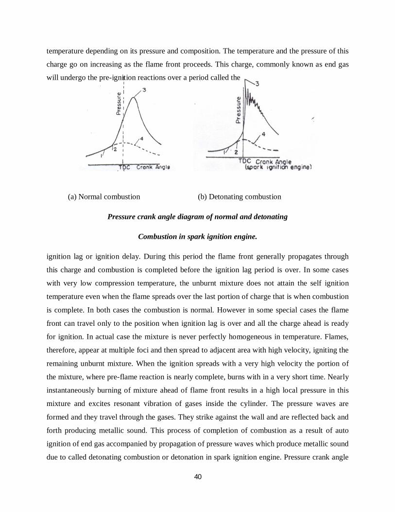
temperature depending on its pressure and composition. The temperature and the pressure of this
charge go on increasing as the flame front proceeds. This charge, commonly known as end gas
will undergo the pre-ignition reactions over a period called the
(a) Normal combustion (b) Detonating combustion
Pressure crank angle diagram of normal and detonating
Combustion in spark ignition engine.
ignition lag or ignition delay. During this period the flame front generally propagates through
this charge and combustion is completed before the ignition lag period is over. In some cases
with very low compression temperature, the unburnt mixture does not attain the self ignition
temperature even when the flame spreads over the last portion of charge that is when combustion
is complete. In both cases the combustion is normal. However in some special cases the flame
front can travel only to the position when ignition lag is over and all the charge ahead is ready
for ignition. In actual case the mixture is never perfectly homogeneous in temperature. Flames,
therefore, appear at multiple foci and then spread to adjacent area with high velocity, igniting the
remaining unburnt mixture. When the ignition spreads with a very high velocity the portion of
the mixture, where pre-flame reaction is nearly complete, burns with in a very short time. Nearly
instantaneously burning of mixture ahead of flame front results in a high local pressure in this
mixture and excites resonant vibration of gases inside the cylinder. The pressure waves are
formed and they travel through the gases. They strike against the wall and are reflected back and
forth producing metallic sound. This process of completion of combustion as a result of auto
ignition of end gas accompanied by propagation of pressure waves which produce metallic sound
due to called detonating combustion or detonation in spark ignition engine. Pressure crank angle

41
diagrams of detonating combustion figure Shows pressure oscillations at the end of combustion
with gradually diminishing pressure peaks. The frequency of these pressure oscillations is the
same as fundamental frequency of the knocking sound. It depends on the velocity of the pressure
wave and the distance between consecutive reflections from the wall of combustion chamber.
Pressure effects
(i) A higher compression ratio, which increases the pressure and temperature of the last portion
of the charge to burn
(ii) An increase in inlet manifold pressure due to more throttle opening or due to supercharging.
Temperature effects
(i) A higher mixture temperature due to manifold heating higher atmospheric temperature, super
charging or increased compression ratio.
(ii) A higher temperature of cooling water in the jacket which reduces cooling of the last portion
of the charge to burn.
Time effects
(i) A lower value of ignition delay due to use of lower octane number fuel
(ii) A lower value of flame velocity due to lower r.p.m of the engine or due to lower intensity of
turbulence caused by combustion chamber design.
FACTORS AFFECTING KNOCK
1. Decreasing the compression ratio or reducing the inlet pressure
2. Decreasing the inlet air temperature
3. Decreasing coolant inlet air temperature
4. Retarding spark timing
5. Decreasing the load
6. Increasing octane rating of the fuel

42
7. supplying rich or lean mixtures
8. Increasing the humidity of the entering air
9. Stratifying the mixture so that the end gas is less reactive
10. Increasing the turbulence of the mixture and thus increasing the flame speed.
Discuss with the help of suitable sketches the following:
a)Wet sump lubrication (b)Dry sump lubrication
ENGINE LUBRICATING SYSTEMS
Engine lubrication system means lubrication of main engine parts like main bearings, connecting
rod bearings, wrist pins, camshaft bearings and cams, cylinder walls, valves and timing drive.
Equipments like starter, generator, water pump and distributor are separately lubricated. The
engine lubrication system circulates oil from a common sump or reservoir at the bottom of the
crank case and may be called Wet sump lubrication. This can be classified as
(i) Full pressure system
(ii) Splash system and
(iii) Modified splash system.
Figure 19. Full pressure lubricating system.

43
Full pressure system has been shown schematically, figure 19. Oil is forced through different
parts under pressure by a geared pump to most of the various rotating and reciprocating parts. Oil
enters the connecting rod bearings and crankshaft through drilled passages. A nozzle is
sometimes placed on the upper end of the connecting rod to spray oil, as a coolant, on the
underside of the piston crown (as in diesel engine). Overhead valve engines have an oil line
leading to a hollow rod which supports the rocker anus. Oil can then flow through the rocker
arms, to valve stems and tappets and down to the valve guides. This system is best suited for
large engines.
Figure 20. Splash system for a single cylinder engine
Small engines usually have a splash system, shown in figure 20. The level of oil is maintained at
a particular level in the sump. The connecting rod is supplied with dippers on the end and they
splash the oil on the various parts as they travel through oil troughs at the bottom of the stroke.
A pump is usually employed to carry the oil to the troughs. Excess oil supplied falls back
into the sump under the action of gravity.
Modified splash system is a combination of the full pressure and splash system. The main
and crankshaft bearings are lubricated on the principles of full pressure system and the
connecting rod bearings are lubricated by means of dippers as shown in Figure 21.

44
Since it is not possible even with the finest gauge to filter all the minute particles of grit and
abraded metal which cause wear of bearings, it is essential to have in the oil circuit adequate
filters of large total area for the removal of all dangerous abrasive materials. Therefore, two
filters in the circuit one before the pump and the other after the pump are provided. The gear
pump produces the required pressure in the system and is driven by the camshaft. An oil pressure
gauge is provided to indicate satisfactory oil supply.
Figure 21. Splash system for a four cylinder engine.
Mist Lubrication System- In most of the two-stroke engines, the charge enters the
crankcase through reed valve while the piston is describing the inward stroke (moving towards
TDC) and is compressed in the crankcase when the piston describes the expansion stroke. Thus,
two-stroke engines are not suitable for crankcase lubrication.

45
Figure 22. Wet sump lubrication system
The full pressure or forced system of lubrication can be either Wet sump or the dry sump
system. In the wet sump system (Figure 22) there is only one pump which draws its oil from the
bulk supply contained in the sump formed in the lower half of the crank case.
Therefore 2 to 3 percent lubricating oil (a fuel/oil ratio of 40 to 50:1 is the optimum for
good performance) is mixed with the fuel (gasoline) in fuel tank. When the mixture passes
through the carburetor, the gasoline, being more volatile, vapourizes and mixes with air. The oil
which is less volatile enters the crankcase as a mist and goes to the cylinder for lubrication. The
oil impinging on the crankcase walls lubricates the main and connecting rod bearings. Some oil
enters the engine cylinder with the vapourized fuel and lubricates the piston, piston rings and
cylinder.
Explain briefly working principle of simple carburetor?
SIMPLE CARBURETOR
The simple plain carburetor shown in figure 9 works on the basic principles underlying
all carburetors. All modem commercial carburetors have evolved from this simple plain-tube

46
carburetor. The basic components are: a venturi, a fuel nozzle with metering orifice, a fuel
reservoir with a float, a throttle and a choke. When the piston describes the suction stroke, there
is a depression in the induction system and the air before entering the engine cylinder, enters the
intake section of the carburetor through the air cleaner which removes the Suspended particles in
air. The air then enters the venturi which is a convergent divergent nozzle, because this shape of
the venturi has the minimum pressure loss. Since the same quantity of air has to pass through
every point of this channel of varying cross-sectional area, the velocity of air at the throat is
maximum and the pressure is minimum (maximum depression) at that section.
Figure 9. Schematic diagram of a simple float type carburetor.
The level of fuel in the reservoir (also called the float chamber) is maintained at a
constant level by the float. A small vent-hole is provided in the lid of the float chamber to ensure
that the free surface of the fuel is always subjected to atmospheric pressure. Since the pressure
inside the float chamber is always atmospheric and is greater than the pressure at the throat of the
venturi, i.e, at the fuel discharge nozzle tip, the fuel flows through the calibrated orifice to the
fuel discharge nozzle. A fuel pump is used to pump fuel from the fuel storage tank to the float
chamber of the carburetor through the needle valve. When the level of the fuel in the float
chamber falls below a fixed level, the needle valve opens the fuel passage admitting more fuel in
the float chamber. With the increase in the level of the fuel inside the float chamber, the float

47
rises and closes the fuel passage, thus maintaining a constant level of fuel in the float chamber.
The fuel comes out of fuel discharge nozzle like a stream of liquid droplets. These droplets
disintegrate into smaller droplets while moving with the air stream and during this process of
disintegration fuel vapourizes from its droplet surfaces. The fuel-air mixture flows through the
diverging section of the venturi where the flow decelerates and some pressure recovery occurs.
It has been found that the vapourization of fuel particles inside the carburetor is very
limited and the major portion of the fuel vaporizes in the intake manifold. Since fuel droplets
may also enter the cylinder in the liquid form and these get evaporated and mix with air during
suction and compression stroke of the piston. The degree of atomization inside the carburetor
depends upon the relative velocity of air and fuel streams and the fuel properties (density, surface
tension etc.).
After the venturi, air fuel mixture flows past the throttle plate before entering the intake
manifold. The speed and power of the engine is controlled by the use of this throttle plate which
is a form of a damper placed between the mixing chamber (venturi) and the intake manifold.
With the opening or closing of the throttle, the obstacle to the flow of mixture increases or
decreases. When the throttle is closed, a very small amount of air and fuel will enter the engine
cylinder and the pressure inside the engine cylinder during the suction stroke of the piston would
be much lower than the atmospheric pressure. This would result in a lower pressure at the end of
compression stroke and also after combustion. Since the pressure exerted on the piston and the
turning effort applied on the crankshaft depends upon the quantity of fuel burned in each
cylinder per cycle, the speed of the engine would also be lower during the closed throttle
position. When the throttle is gradually opened, the speed of the engine will gradually increase
and thus, the speed of the engine is controlled by opening or closing the throttle. If the engine is
connected to a load, the speed of the engine can be maintained constant by varying the throttle
position with respect to load.
The other basic component of the carburetor is the choke inserted in the air-intake
passage of the carburetor. The choke enables the engine to receive an additional amount of fuel
(a rich mixture) for starting the engine under cold conditions. By closing the choke, the quantity

48
of air flowing through the venturi is drastically reduced and the suction of the engine exerts
directly on the fuel discharge nozzle to cause fuel to flow.
In the simple carburetor, shown in Figure 8.2, the fuel flows from the float chamber
through the fuel discharge nozzle because of the pressure difference between the atmospheric
pressure in the float chamber and the pressure at the throat. And, this pressure difference has to
overcome the surface tension effects also at the nozzle exit. When the speed of the engine is low,
i.e., when the throttle is almost closed, the quantity of air flowing through the venturi is very
small and the vacuum created at the venturi is insufficient to draw fuel into the air stream. When
the speed of the engine increases, the quantity of air flowing through the venture increases and
this creates a large vacuum at the throat. Therefore, a proportionally greater amount of fuel is
sprayed into the air stream. Thus a simple carburetor has a tendency to supply a rich mixture (>
1) at higher speeds of the engine and a weak mixture ( < 1) at lower speeds.
Different types of combustion chambers used in CI engines ?
COMBUSTION CHAMBERS
The most important function of the CI combustion chamber is to provide proper mixing
of fuel and air in a short time. In order to achieve this an organized air movement called the air
swirl is provided to produce high relative velocity between the fuel droplets and the air. The fuel
is injected into the combustion chamber by an injector having single or multihole orifices. The
increase in the number of jets reduces the intensity of air swirl needed.
CI engine combustion chambers are classified into two categories
Direct injection (DI) type: This type of combustion chamber is also called an open combustion
chamber. In this type the entire volume of the combustion chamber is located in the main
cylinder and the fuel injected into this volume.
Indirect –injection (IDI) type: the combustion space is divided into two parts one part in the
main cylinder and other part in the main cylinder. The fuel injection is effected usually into that
part of the chamber located in the cylinder head. These chambers are classified further into

49
Swirl chamber in which compression swirl is generated
Pre combustion chamber in which combustion swirl is induced
Air cell chamber in which both compression and combustion swirl are induced
Direct –injection chambers:
An open combustion chamber is defined as one in which the combustion space is
essentially a single cavity with little restriction from one part of chamber to the other and hence
with no large difference in pressure between the parts of the chamber during the combustion
process. There are many designs of open chambers some of which are shown .
Shallow depth chamber: The depth of cavity provided in the piston is quiet small. This
chamber is usually adopted for large engines running at low speeds. The cavity diameter is very
large the squish is negligible.
Hemispherical chamber: This chamber also gives small squish .However the depth to
diameter ratio for a cylindrical chamber can be varied to give any desired squish to give better
performance.
Fig .Open combustion chambers

50
Cylindrical chamber:
This design is attempted in recent diesel engines. This is a modification of cylindrical
chamber in the form of a truncated cone with base angle of 30º. The swirl was produced by
masking the value for nearly 180º of circumference. Squish can also be varied by varying the
depth
Toroidal chamber
The idea behind the shape is to provide a powerful squish along with the air movement
similar to that of the familiar smoke ring within the toroidal chamber. Due to the powerful squish
the mask needed on inlet valve is small and there is better utilization of oxygen. The cone angle
of spray is 150º to 160º.
2.3.2 Indirect –injection chambers: A divided combustion chamber is defined as one
in which the combustion space is divided into two or more distinct compartments connected by
restricted passages. This creates considerable pressure differences between them during the
combustion.
Swirl chamber:
It consists of a spherical shaped chamber separated from the engine cylinder and
located in the cylinder head. Into this chamber about 50% of air is transferred during the
compression stroke.
A throat connects the chamber to the cylinder which enters the chamber in a tangential
direction so that the air coming into this chamber is given a strong rotary movement inside the
swirl chamber and after combustion the products rush back into the cylinder through the same
throat at much higher velocity.
This cause considerable heat loss to the walls of the passage which can be reduced by
employing a heat insulated chamber. In this type of combustion chambers even with heat
insulated passage the heat loss is greater than that in an open combustion chamber which
employs induction swirl

51
Fig .Ricardo swirl chamber comet mark ΙΙ
Precombustion chamber:
A typical precombustion chamber consists of an anti chamber connected to the main
chamber through a number of small holes. The precombustion chamber is located in the cylinder
head and its volume accounts for40% of total combustion space. During the compression stroke
the piston forces the air into the precombustion chamber.
The fuel injected into the prechamber and the combustion is initiated. The resulting
pressure rise forces the flaming droplets together with some air and their combustion products to
rush out into the main cylinder at high velocity through the small holes.
Thus it creates both strong secondary turbulence and distributes the flaming fuel droplets
throughout the air in the main combustion chamber where bulk of combustion takes place. About
80% of energy is released in main combustion chamber

52
Fig. Pre combustion chambers
Air cell chamber: The clearance volume is divided into two parts one in the main cylinder and
other called the energy cell. The energy cell is divided into two parts major and minor which are
separated from each other and from the main chamber by narrow orifice. A pintle type on nozzle
injects the fuel across the main combustion chamber space towards the open neck of the air cell.
During compression the pressure in the main chamber is higher than that inside the
energy cell due to restricted passage area between the two. At the TDC the difference in the
pressure will be high and air will be forced at high velocity through the opening into the energy
cell and this moment the fuel injection starts. Combustion starts initially in the main chamber
where temperature is comparatively higher but the rate of burning is very slow due to the
absence of any air motion. In energy cell the fuel is well mixed with air and high pressure is
developed due to heat release and hot burning gases blow out through the small passage into the
main chamber.

53
Fig . Lanova air-cell combustion chambers
This high velocity jet produces the swirling motion in the main chamber and thereby
thoroughly mixes the fuel with air resulting in complete combustion. The design is not suitable
fir variable speed operation as the combustion induced swirl has no relationship to the speed of
the engine. The energy cell is designed to run hot, to reduce ignition lag.

54
MAY 2013
Different types of combustion chambers in SI engines?
COMBUSTION CHAMBERS:
Different types of combustion chambers for SI engines are developed over a time. Brief
descriptions of those combustion chambers are given below.
T-Head type:
It is used in early stage of engine development. Since the distance along the combustion
chamber is very long , knocking tendency is high in this type of engines. This configuration
provides two valves on either side of the cylinder requiring two camshafts.
L-Head type:
It is a modification of L type which provides the two valves on the same side of the
cylinder and the valves are operated by a single camshaft. The main objective of the Ricardo’s
turbulent head design are to obtain fast flame speed and reduced knock.
The main body of the combustion chamber is concentrated over the valves leaving a
slightly restricted passage communicating with the cylinder thereby creating the additional
turbulence during the combustion stroke.
Fig. Examples of typical combustion chamber

55
I-Head type or Overhead valve:
Both the valves are located on the cylinder head. The overhead valve engine is superior to the
side valve at high compression ratios. Some important characters are
Less surface to volume ratio and therefore less heat loss
Less flame travel length and hence greater freedom from knock
Higher volumetric efficiency from larger valves
Confinement of the thermal failures to the cylinder head by keeping the hot exhaust
valve in the head instead of the cylinder block
F-Head type:
The valve arrangement is a compromise between L head and I head types. Combustion
chambers in which one valve is in the cylinder head and other in cylinder block are known as F
head type combustion chambers. Modern F head engines have exhaust valve in the head and inlet
valve in the cylinder block.
Explain with the help of Pressure-crank angle diagram different stages combustion in CI
engines?
STAGES OF COMBUSTION IN CI ENGINES
The combustion in a CI engine is considered to be taking place in four stages. It is
divided into the ignition delay period, the period of rapid combustion, the period of controlled
combustion and the period of after-burning. The details are explained below.
Ignition Delay Period
The ignition delay period is also called the preparatory phase during which some fuel has
already been admitted but has not yet ignited. This period is counted from the start of injection to
the point where the pressure-time curve separates from the motoring curve indicated as start of
combustion in figure.
56
The delay period in the CI engine exerts a very great influence on both engine design and
performance. It is of extreme importance because of its effect on both the combustion rate and
knocking and also its influence on engine starting ability and the presence of smoke in the
exhaust.
The fuel does not ignite immediately upon injection into the combustion chamber. There
is a definite period of inactivity between the time when the first droplet of fuel hits the hot air in
the combustion chamber and the time it starts through the actual burning phase. This period
known as the ignition delay period. In fig the delay period is shown on pressure crank angle
diagram between points (a) and (b). point a represents the time of injection and point b represents
the time at which the pressure curve first separates from the motoring curve. The ignition delay
period can be divided into two parts, the physical delay and the chemical delay.
Physical delay:
The physical delay in the time between the beginning of injection and the attainment of
chemical reaction conditions. During this period the is atomized, vaporized, mixed with air and
raised to its self-ignition temperature.
This physical delay depends on the type of fuel, i.e., for light fuel the physical delay is
small while for heavy viscous fuels the physical delay is high.
The physical delay is greatly reduced by using high injection pressures, higher
combustion chamber temperatures and high turbulence to facilitate breakup of the jet and
improved evaporation.

57
Fig 2.1 Stages of combustion in CI engine
Fig . Pressure time diagram illustrating ignition delay

58
Chemical delay:
During the chemical delay, reactions start slowly and then accelerate until
inflammation or ignition take place. Generally the chemical delay is larger than physical delay.
However it depends on the temperature of surroundings and at high temperatures the chemical
reactions are faster and the physical delay becomes longer than the chemical delay. It is clear that
the ignition lag in SI engine is essentially equivalent to the chemical delay for the CI engine. In
most CI engines the ignition lag is shorter than the duration of injection.
Period of rapid combustion:
The period of rapid combustion also called the uncontrolled combustion is that phase in which
the pressure rise is rapid. During the delay period the droplets have bad time to spread over a
wide area and fresh air is always available around the droplets. Most of the fuel admitted would
have evaporated and formed a combustible mixture with air. By this time the pre flame reactions
would have also been completed. The period of rapid combustion is counted from end of delay
period. The rate of heat release is maximum during this period. The pressure reached during the
period of rapid combustion will depend on the duration of the delay period.
Period of controlled combustion:
The rapid combustion period is followed by the third stage the controlled
combustion. The temperature and pressure in the second stage is already quite high. Hence the
fuel droplets injected during the second stage burn faster with reduced ignition delay as soon as
they find the necessary oxygen and further pressure rise is controlled by the injection rate. The
period of controlled combustion is assumed to end at maximum cycle temperature.
Period of after burning: combustion does not cease with the completion of the injection
process. The unburnt and partially burnt fuel particles left in the combustion chamber start
burning as soon as they come in contact with the oxygen. This process continues for a certain
period called the after burning period. Usually this period starts from the point of maximum
cycle temperature and continues over a part of expansion stroke .Rate of after burning depends
on the velocity of diffusion and turbulent mixing of unburnt and partially burnt fuel with air. The
duration of the after burning phase may correspond to 70-80 degrees of crank travel from TDC.

59
MAY2012
Combustion Process of Spark Ignition Engine
Phase of Combustion
In spark ignition engines a sufficiently homogeneous mixture of vaporized liquid fuel, air
and residual gases is ignited by an electric spark. The charge near the spark gap burns soon after
the spark is applied. A flame develops and it spreads progressively over the entire mixture.
From the flame trace, it can be observed that flame travel can be divided into three
periods. Each of these periods constitutes one phase of the combustion process.
The First Phase
This is the initial phase of low but rapidly increasing flame velocity. A small volume of
mixture in the very high temperature zone between the spark plug electrodes ignite soon after the
spark is applied. The burning gases gradually transform into a developed flame front. At the
beginning the volume of mixture taking part in combustion is small. The flame velocity is also
low since the decreased due to heat transfer to the adjacent cylinder walls. As a result the rate of
energy release during this phase is low. Therefore, the pressure rise inside the cylinder due to
combustion is not appreciable.
Second Phase
This is the period of practically constant flame velocity. During this phase the flame front
rapidly spreads over the major part of the mixture. The rate of combustion is high due to the
influence of large scale turbulence. Heat transfer to the cylinder wall is low because only a small
part of the burning mixture comes in contact with the cylinder wall during this period. The rate
of heat of release during this phase depends largely on the turbulence intensity and to a lesser
extent on reaction rate dependent on mixture combustion. The rate of pressure rise is
proportional to the rate of heat release because during this phase the combustion chamber
volume remains practically constant. The beginning of this phase of combustion in spark ignition
engine is taken at the point where the curve of combustion separates from the curve of
compression in the pressure crank angle diagram fig1.1.

60
1 – Spark point, 1-2 – Firs phase,
2-3 – Second Phase, 3-4 – Third phase,
5 – Curve with no combustion.
Fig. Pressure versus crank angle diagram of a spark ignition engine
Third Phase
During this phase of combustion the flame velocity decreases. The flame front here
approaches the wall of the combustion chamber where the turbulence intensity is low. The
temperatures of the mixture layers are comparatively low due to increased heat transfer through
the walls. All these factors decrease the flame velocity. The combustion rate becomes low due to
low flame velocity and reduced surface of flame front. There is practically no pressure rise
during this phase due to expansion of the gas. The starting point of this phase is usually taken as
the instant at which the maximum pressure is reached on the indicator diagram.

61
Explain Influence of some important factors on combustion?
Composition of mixture
The composition of the mixture specified by the air coefficient influences the rate of
reaction and the amount of heat release. This also affects the pressure and temperature of the
gases in an engine cylinder.
Experimental data obtained during the engine test using different air coefficient show that
with optimum ignition advance corresponding to best power condition in each case, the power
developed by the engine is the maximum where ranges between 0.85 to 0.9. The velocity of
flame propagation also has highest value for this mixture. When the air co efficient is increased
above 0.9, the maximum pressure of the cycle drops decreasing the output of the engine. When
the mixture is made much leaner the combustion in the engine becomes unstable due to reduced
flame velocity.
Compression ratio
The pressure and temperature of the mixture at the beginning of combustion are increased
by increasing the compression ratio. The concentration of residual gases in the mixture is also
reduced at high compression ratio. Both these factors increase the rate of combustion in the main
phase and reduce the duration of the initial phase. However, high compression ratio increases the
last phase of combustion resulting in comparatively hot exhaust.
Load
When an engine operates on part load the inlet pressure is reduced by partially closing the
throttle valve. This results in reduced compression pressure and larger concentration of residual
gases. Both these factors reduce the flame velocity and prolong the initial phase of combustion.
Combustion process also becomes unstable due to low concentration of fuel in the mixture. The
difficulty can be over come by enrich the mixture at very low loads. Rich mixture at low loads
enhances the presence of unburnt products in the exhaust gas.

62
Speed
With increase in speed the turbulence intensity in the mixture increases. The velocity of
the flame front increases due to increased turbulence intensity and therefore, the duration of
combustion process become shorter. With optimum ignition of advance in each speed the effect
of increased speed on the last phase of combustion is compensated by reduced heat transfer. The
efficiency of combustion process practically remains the same when speed is changed.
Shape of combustion chamber
A centrally located spark plug in a hemispherical combustion chamber will reduce the
path traveled by the flame front. The surface area of the flame front is also increased. As a result
the rate of heat release is higher than other types of combustion chambers. The turbulence
intensity in the mixture can be increased by properly shaped combustion chamber with a narrow
passage between the piston crown and the bottom of cylinder head through which the charge
flows to the combustion chamber. With suitable design of combustion chamber the heat release
rate can be increased.
When an engine operates on part load the inlet pressure is reduced by partially closing the
throttle valve. This results in reduced compression pressure and larger concentration of residual
gases. Both these factors reduce the flame velocity and prolong the initial phase of combustion.
Combustion process also becomes unstable due to low concentration of fuel in the mixture. The
difficulty can be over come by enrich the mixture at very low loads. Rich mixture at low loads
enhances the presence of unburnt products in the exhaust gas.

63
Unit – V
1. Following data refer to a four stroke double acting diesel engine having cylinder
Diameter 200 mm and Piston stroke 350 mm.
MEP on cover side = 6.5 bar
MEP on crank side = 7 bar
Speed = 420 rpm
Diameter of the Piston rod = 20mm
Dead load on the brake = 1370 N
Spring balance reading = 145 N
Brake wheel diameter = 1.2 m
Brake rope diameter = 20 mm
Calculate mechanical efficiency
Given
Double acting 4 stroke Diesel engine
D = 200 10-3m
L = 350 10-3 m
Pm1 = 6.5 bar
Pm2 = 7 bar
N = 420 rpm
d = 2010-3 m
s = 145 N
Dw = 1.2 m
dr = 2010-3 m
To find IPBP
m
kW60
APAPLNw100IP 22m21m ][
NW = 2102
4202N rpm (4 Stroke)

64
21 D
4A
= 23102004
)(
= 0.0314 m2
211 d
4AA
= 0.0314 - 2310204
)(
= 0.0314 - ))(( 33 102010204
= 0.0310 m2
IP = 60
031007031405621010350100 3 )...[
= 51.66 kW
To find BP (Rope brake dyna)
BP = 60
NdDsw rw )()(
= 60
4201020211451370 3 ).()(
= 32.86 kW
63066578632
m ... = 63%
2. A single cylinder four stroke diesel engine having a swept volume 730 cm3 is tested at
300 rpm when a braking torque of 65 N is applied to mean effective pressure of 1100
kN/m2 calculate Brake Power and mechanical efficiency.
Solution
B.P = kW60NT2
PIPB
mech ..
I.P = 60
LANpm100

65
B.P = 60
65300260NT2
= 2.042 kw
IP = 60
LANpm100
= 60
1501075011100 6
= 2.0625 kW
062520422
PIPB
mech ..
..
= 99%
3. A four cylinder two stroke petrol engine develops 20 kW brake power and runs at 2500
rpm. Design an engine which is having 8 bar mean effective pressure on 85%
mechanical efficiency take stroke of an engine is 1.5 times of bore.
Given
4 Cylinder, 2 stroke, SI engine
BP = 20 kW
N = 250 rpm
pm = 8 bar
m = 85% = 85
L = 1.5 D
Find D, L (Design)
PIPB
m ..
85 IP20
IP = 8520
IP = 522385
2000 . kW
IP = 60
LANp100K wm
K = Number of cylinder

66
Nw = N (2 stroke)
23.52 = 604
2500D50181004 2
.
23.52 460 = 41008250 1.5 D D2
D D2 = 51250800
0523.14
64.2
D3 = 1.49710-3
D = 1.14410-3 m
L = 1.5 D = 1.716 10-3 m
4. A four cylinder diesel engine works on lower stroke has cylinder bore of 90 mm and the
stroke of 150mm. The crank speed of 370 rpm fuel consumed by the engine 15 kg/hr
and its calorific value 39000 kJ/kg the indicated mean effective pressure is 5 bar of
compression ratio of an engine is 14 and cut off ratio is 2.3. Calculate relative efficiency
of an engine if =1.4
Given
4 cylinder, 4 stroke Diesel engine
K = 4, Nw = 2N , D = 9010-3m
L = 15010-3, N = 370 rpm
Indicated.m.e. p = 5 bar
mf = 15 kg/hr
CV = 39000 kJ/kg
r = 14
Cut-off = 2.3
v = 1.4
Find
relative
Solution
efficiency standardAir
efficiency thermalIndicatedrelative
To find In th

67
CVmf3600IP
thI
.
IP = kw60
LANpm100K w.
= 460
18510901015051004 33
= 5.8 kW
To find
39001536008.5
.
thI0
= 3.52 %
air std =
)()( 1p1
r11
v
1
=
).(.
).()(
.
. 13241132
1411
41
40
= 0.57 %
Now, re = %... 356570623
5. The following particular obtain in trial in a 4 stroke gas engine
Duration of trial = 1 hr
Revolution = 14000
No. of missed cycle = 500
Net load = 1470N
Mean eff. Pressure = 7.5 bar
Gas consumption = 20000 lit
L.C.V. of gas supply condition = 21 KJ/lit
Cylinder Diameter = 250mm
Stroke = 450mm
Effective break circumference = 4m
Compression ratio = 6.5
Determine (1) IP (2) BP (3) m (4) I. th (5) relative

68
Given data
4 stroke gas engine (Petrol) (Otto cycle)
Duration = 1 hr
Nw=2N =
214000 = 7000 rpm
Missed cycle = 5002 = 1000 rpm
Net speed (Nw) = 14000-1000 = 13000 rpm
(W-S) = 1470 N
pm = 7.5 bar
mf = 20,000 lit
LCB = 21 kJ/lit
D = 250 10-3 m
L = 40010-3 m
D = 4 m
r = 6.5: 1 = 6.5
Now,
B.P = 60
66216250147060
DNSW ..)(
B.P = 4.16 kW
I.P = 60
65002504
4057100
60LANwpm100
2
...
= 1595.34 KW
To find BP
BP = 60
NDSW .)(
= 60
1300041470
= 1274 kw
To find mech = PIPB
..

69
= 341595
1274.
= 79.85 %
To find I.thermal
I thermal = VCmf
3600PI.
.
= 2120003600341595
.
= 13.67 %
To find relative = assisted
thI
.
1r
11 vair
)(
6. A test was conducted in a 4-stroke single cylinder SI engine having 7 cm diameter and 9
cm stroke. The fuel supply to the engine is 0.065 kg/m. The B.P measurements are given
below with constant speed of an engine.
1. With all cylinder firing = 16.9 kW
2. Cut off at 1st cylinder = 8.46 kW
3. Cut off at 2nd cylinder = 8.56 kW
4. Cut off at 3rd cylinder = 8.6 kW
5. Cut off at 1st cylinder = 8.46 kW
If clearance volume 69.5 cm3 find Indicate Power, Indicated thermal efficiency also compare the
thermal efficiencies.
Take CV = 43500 kJ/kg
Solution
Given
4S, SI engine
D = 7 cm
L = 9 cm
mf = 0.065 kg/min
CV = 43500 KJ/kg
BP = 16.9 kW

70
Vc = 69.5
BP1 = 8.46 kW
BP2 = 8.56 kW
BP3 = 8.6 kW
BP4 = 8.5 kW
Find
(i) IP (ii) In th (iii) rel=
StdAirthIn.
Solution
IP1 = BP-BP1
IP1 = 16.9 – 8.46
IP1 = 8.44 Kw
IP2 = BP – BP2
= 16.9 – 8.56
IP2 = 8.34 kW
IP3 = BP-BP3
= 16.9-8.6
IP3 = 8.3 kW
IP = IP1+ IP2 + IP3 +IP4
= 8.44+8.34+8.3+8.4
IP = 33.48 kW
In th = 435000650
604833CVmf60IP
..
In th = 71.04%
1air r11 )(
VolumeVolumeTotalratio)ionr(compress
= c
sc
VVV
Vs = LD4
2

71
= 974
2
= 9494
= 346.36 cm3
r = 985669
36346669 ..
..
40air 98511 .).(
air = 51.09%
rel = air
thIn
. = 1.39%
7. The following observation where recorded in a test of hour duration a single cylinder oil
engine on four stroke cycle.
Bore = 300 mm
Stroke = 450 mm
Fuel used = 5.5 kg
Calorific value = 41800 kJ/kg
Avg. speed = 200 rpm
Brake load = 1860 N
MEP = 5.8 bar
Quantity of cooling water = 650 kg
Temperature rise in water = 22oC
Diameter of brake wheel = 1.22 m
Calculate Mech efficiency, B th also draw heat balance sheet
Solution
Given data, SS, 4S, SI engine
D = 0.3m Tw = 22oC
L = 0.45m Dw = 1.22m
mf = 8.8 kg/hr R = 2221. =0.61 m

72
CV = 41800 kJ/kg
N = 2.00 rpm
W = 1860 N
pm = 5.8 bar
mw = 650 kg/hr
BP = 60NT2 kW
(Bony Brea)
Brake Torqu (T) = w.R
= 18600.61 N-m
= 1134.6 J,
BP = 60NT2
= 60
611342002 .
= 23763.006 W
BP = 23.75 kW
IP = 60
KANwpm100
= 60
1045085100 3 .
IP = 30.74 kW
m = IPBP
= 10074307523
.
.
= 77.3 %
To find B th
4180088
36007523CVmf
3600BPBth
..
= 23.25 %
For the Heat Balance Sheet

73
Total Heat supply by the fuel
Heat supply = mf CV
mf = 8.8 Rg/hr
CV = 41800 kJ/kg
Qs = 8.8 41800
= 60
8678400 kJ/hr = 6130 kJ/min
Heat absorb to produce indicated power
I.P = 60
LAN p 100 m kW
I.P = 30.74 kW
= 30.74 60 = 1844.4 kJ/min
Heat rejected cooling water
QCW = mcw Cpw (Two-Tci)
QCW = mcw Cpw (T)cw
= 650/60 4.2 (2)
= 997.66 KJ/min
Heat carried away by the exhaust Gases
Qg = mg Cpg (T)g = 0
because it is not given
Uncountable Heat
Qs- (IP + QRW+Q)
= 3673400-(110664+60060) = 3507676 kJ/hr.
% Q to I.P = 100Qs
PItoQ
.
= 100367840018444
% Q to Cw = 68613010066997
..
= 16.27%
% Q to exhaust Gas = 0
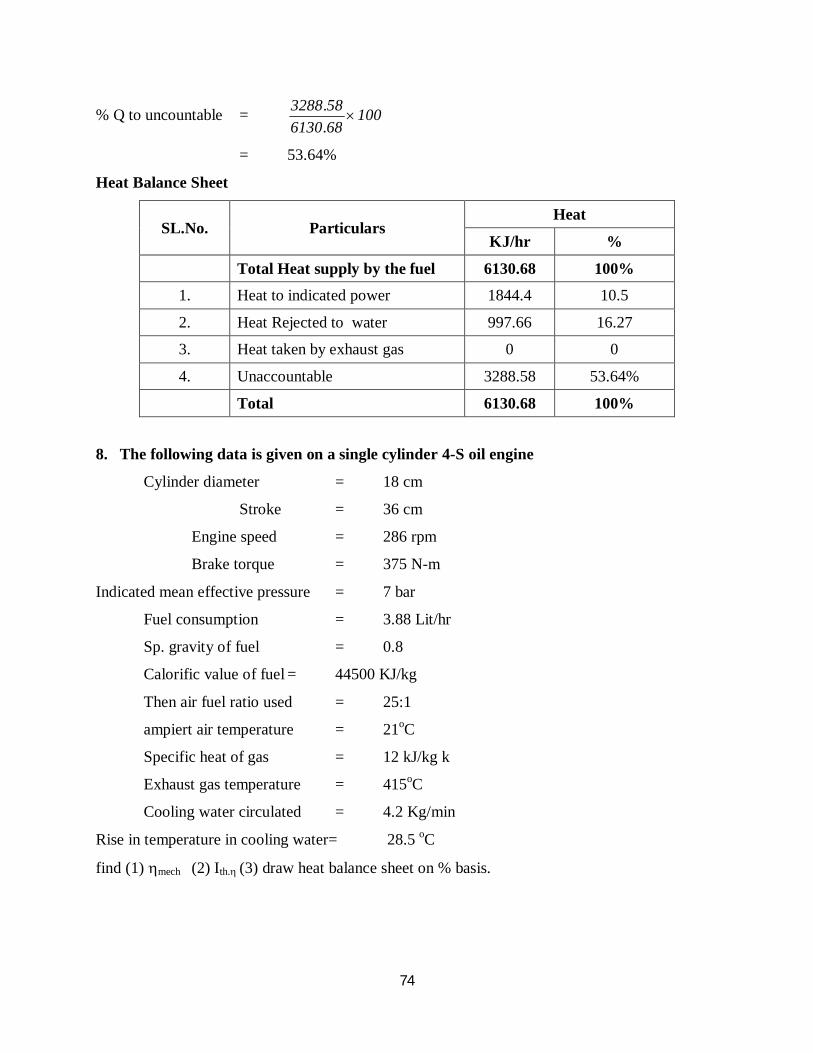
74
% Q to uncountable = 100686130583288
.
.
= 53.64%
Heat Balance Sheet
SL.No. Particulars Heat
KJ/hr %
Total Heat supply by the fuel 6130.68 100%
1. Heat to indicated power 1844.4 10.5
2. Heat Rejected to water 997.66 16.27
3. Heat taken by exhaust gas 0 0
4. Unaccountable 3288.58 53.64%
Total 6130.68 100%
8. The following data is given on a single cylinder 4-S oil engine
Cylinder diameter = 18 cm
Stroke = 36 cm
Engine speed = 286 rpm
Brake torque = 375 N-m
Indicated mean effective pressure = 7 bar
Fuel consumption = 3.88 Lit/hr
Sp. gravity of fuel = 0.8
Calorific value of fuel = 44500 KJ/kg
Then air fuel ratio used = 25:1
ampiert air temperature = 21oC
Specific heat of gas = 12 kJ/kg k
Exhaust gas temperature = 415oC
Cooling water circulated = 4.2 Kg/min
Rise in temperature in cooling water= 28.5 oC
find (1) mech (2) Ith. (3) draw heat balance sheet on % basis.

75
(i) Given
SS, 4S oil engine
D = 1810-2 m Ta=21oC
L = 3610-2 m (Cp)gas=1.2 KJ/kgk
N = 286 rpm Tex gas=415oC
T = 375 N mc=4.2 kg/min
pm = 7 bar (T)c=28.5oC
mf = 3.88 lit/hr
specific = 0.8
gravity
CV = 44500 KJ/hr
Air-fuel ratio= 25mm
f
a
ma = 25mf
Solution
mf = 3.88 lit/hr
= 3.88 10-3 m3/hr
WKT
= Vm
m = v
= 8003.8810-3
= 3.10 kJ/hr
sp.gr = substance std ofdensity
fuel ofDensity
= water
f
f = Sp. gv w
= 0.8100
= 800 kg/m3
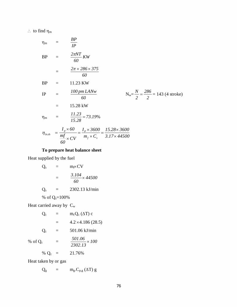
76
to find m
m = IPBP
BP = KW60NT2
= 60
3752862
BP = 11.23 KW
IP = 60
LANwpm100 Nw=2
2862N = 143 (4 stroke)
= 15.28 kW
m = %... 197328152311
4450017336002815
Cm3600I
CV60mf
60I
vf
PpthIn
..
.
To prepare heat balance sheet
Heat supplied by the fuel
Qs = mfCV
= 44500601043 .
Qs = 2302.13 kJ/min
% of Qs=100%
Heat carried away by Cw
Qc = mcQc (T) c
= 4.2 4.186 (28.5)
Qc = 501.06 kJ/min
% of Qc = 100132302
06501 .
.
% Qc = 21.76%
Heat taken by or gas
Qg = mg.Cp,g (T) g

77
= mg Cpg (Tg-Ta) mass of air = 25601043.
= 1.29 1.2 (415-21) = 1.29 Kg/min
= 609.91 kJ/min
% Qg = 10013230291609 ..
Qg = 26.46%
Unaccounted heat
QIP = 15.28 60
= 916.8 KJ/min
%QIP = 39.8%
Unaccounted heat = Qs - [QIP+Qc+Qg]
= 2302.13 – [916.8+501.06+609.91]
= 274.36 KJ/min
% of Qun = 100132302
35274 ..
= 11.9%
Heat Balance Sheet
SL.No. Particulars Heat
KJ/hr %
Total Heat supply by the fuel 2302.13 100
1. Heat to indicated power 916.8 38.82
2. Heat Rejected to water 501.06 21.26
3. Heat taken by exhaust gas 609.91 29.49
4. Unaccountable 284.36 11.9
Total 4604.26 100%
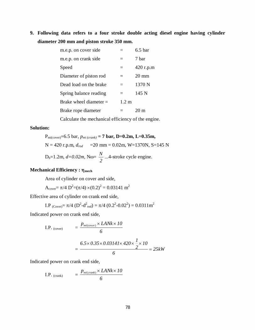
78
9. Following data refers to a four stroke double acting diesel engine having cylinder
diameter 200 mm and piston stroke 350 mm.
m.e.p. on cover side = 6.5 bar
m.e.p. on crank side = 7 bar
Speed = 420 r.p.m
Diameter of piston rod = 20 mm
Dead load on the brake = 1370 N
Spring balance reading = 145 N
Brake wheel diameter = 1.2 m
Brake rope diameter = 20 m
Calculate the mechanical efficiency of the engine.
Solution:
Pmi(cover)=6.5 bar, pmi (crank) = 7 bar, D=0.2m, L=0.35m,
N = 420 r.p.m, drod =20 mm = 0.02m, W=1370N, S=145 N
Db=1.2m, d=0.02m, N= 2N ...4-stroke cycle engine.
Mechanical Efficiency : mech
Area of cylinder on cover and side,
Acover= /4 D2=(/4) (0.2)2 = 0.03141 m2
Effective area of cylinder on crank end side,
I.P (Cover)= /4 (D2-d2rod) = /4 (0.22-0.022) = 0.0311m2
Indicated power on crank end side,
I.P. (cover) = 6
10LANkp ermi )(cov
= kW256
102142003141035056
...
Indicated power on crank end side,
I.P. (crank) = 6
10LANkp crankmi )(

79
= kW67266
10214200314103507
...
Total I.P = 25+26.67 = 51.67 kW
Now, brake power, B.P = kW100060
420020211451370100060
NdDSW b
)..()()()(
= 32.86 kW
Mechanical efficiency, mech = PIPB
.. =
67518632.. = 0.6359 = 63.59% (Ans.)
10. The following particulars were obtained in a trial on a 4-stroke gas engine:
Duration of trial = 1 hour
Revolutions = 14000 Number of missed cycle = 500 Net brake load = 1470N Mean effective pressure = 7.5 bar Gas consumption = 20000 litres L.C.V of gas at supply condition= 21 kJ/litre Cylinder diameter = 250 mm Stroke = 400 mm Effective brake circumference = 4 m Compression ratio = 6.5:1 Calculate: (i) Indicated power (ii) Brake power (iii) Mechanical efficiency (iv) Indicated thermal efficiency (v) Relative efficiency
Solution
N = 8
70060
14000 r.p.m. W-S = 1470 N
Pmi= 7.5 bar; VR= 36002000 = 5.55 litres/s,
D = 250 mm = 0.25 m, L = 400 mm = 0.4 m
Db= 4m, r = 6.5

80
(i) Indicated Power I.P:
I.P. (cover) = 6
10LANp wermi )(cov
Nw = 60
650036005002
14000
/ working cycles/min
= 6
10606500250440571 2 )/(./..
= 26.59 kW (Ans)
(ii) Brake Power,
Now, brake power, B.P = kW8622100060
370041470100060
NdDSW b .)/()()(
(iii) Mechanical Efficiency, mech
mech = PIPB
.. =
59268622.. = 0.859 or 85.9% (Ans.)
(iv) Indicated thermal efficiency, th.(1)
th(1) = %..
.. 23or2302155
5926CV
PI
g
(Ans)
(v) Relative efficiency, relative
dardsair
thermalrelative n tan
52705611
r11 1411dardsair .
).()( .tan or 52.7%
relative = 5270230
.. = 0.436 or 43.6% (Ans)
11. In a trial of a single cylinder oil engine working on dual cycle, the following
observations were made
Compression ratio = 15
Oil consumption = 10.2 kg/h
Calorific value of fuel = 43890 kJ/kg
Air consumption = 3.8 kg/min
Speed = 1900 r.p.m
Torque on the brake drum = 186 N-m

81
Quantity of cooling water used = 15.5 kg/min
Temperature rise = 36oC
Exhaust gas temperature = 410oC
Room temperature = 20oC
cp for exhaust gases = 1.17 kJ/kgK
Calculate : (i) Brake power,
(ii) Brake specific fuel consumption and
(iii) Brake thermal efficiency
Draw heat balance sheet on minute basis.
Solution: n=1, r=15, mf=10.2 kg/h, C=43890 kJ/kg, ma=3.8 kg/min, N=1900 r.p.m.,
T=186 N-m, m=15.5 kg/min, tw2-tw1=36oC, tg=410oC, tr=20oC,
(i) Brake Power, B.P:
B.P = kW37100060
18619002100060NT2
(ii) Brake specific fuel consumption b.s.f.c:
b.s.f.c. = ./.. kWhkg2756037
210
(iii) Brake thermal efficiency,
th(B)=43890
3600210
37Cm
PBf
.. = 0.2975 or 29.75% (Ans.)
= min/. kJ74614389060
210
(i) Heat equivalent B.P
= B.P 60 = 3760 = 2220 kJ/min
(ii) Heat carried away by cooling water
= mwcpg (tg-tr)
= min/)(... kJ1811204101718360
210
`
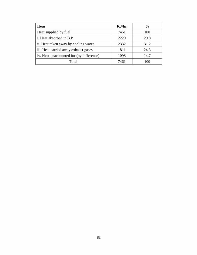
82
Item KJ/hr % Heat supplied by fuel 7461 100 i. Heat absorbed in B.P 2220 29.8 ii. Heat taken away by cooling water 2332 31.2 iii. Heat carried away exhaust gases 1811 24.3 iv. Heat unaccounted for (by difference) 1098 14.7
Total 7461 100


