Heat transfer efficient thermal energy storage for steam generation R. Adinberg * , D. Zvegilsky, M. Epstein Solar Research Facilities, Weizmann Institute of Science, Rehovot 76100, Israel article info Article history: Received 14 April 2008 Received in revised form 7 January 2009 Accepted 12 August 2009 Available online 25 September 2009 Keywords: Thermal storage Zinc alloy Reflux Heat transfer Solar power Steam abstract A novel reflux heat transfer storage (RHTS) concept for producing high-temperature superheated steam in the temperature range 350–400 °C was developed and tested. The thermal storage medium is a metal- lic substance, Zinc–Tin alloy, which serves as the phase change material (PCM). A high-temperature heat transfer fluid (HTF) is added to the storage medium in order to enhance heat exchange within the storage system, which comprises PCM units and the associated heat exchangers serving for charging and dis- charging the storage. The applied heat transfer mechanism is based on the HTF reflux created by a com- bined evaporation–condensation process. It was shown that a PCM with a fraction of 70 wt.% Zn in the alloy (Zn70Sn30) is optimal to attain a storage temperature of 370 °C, provided the heat source such as solar-produced steam or solar-heated synthetic oil has a temperature of about 400 °C (typical for the parabolic troughs technology). This PCM melts gradually between temperatures 200 and 370 °C pre- serving the latent heat of fusion, mainly of the Zn-component, that later, at the stage of heat discharge, will be available for producing steam. The thermal storage concept was experimentally studied using a lab scale apparatus that enabled investigating of storage materials (the PCM–HTF system) simultaneously with carrying out thermal performance measurements and observing heat transfer effects occurring in the system. The tests produced satisfactory results in terms of thermal stability and compatibility of the utilized storage materials, alloy Zn70Sn30 and the eutectic mixture of biphenyl and diphenyl oxide, up to a working temperature of 400 °C. Optional schemes for integrating the developed thermal storage into a solar thermal electric plant are discussed and evaluated considering a pilot scale solar plant with thermal power output of 12 MW. The storage should enable uninterrupted operation of solar thermal electric systems during additional hours daily when normal solar radiation is not sufficient. Ó 2009 Elsevier Ltd. All rights reserved. 1. Introduction High-temperature superheated steam generated in concen- trated solar power plants is an environmentally clean energy car- rier that can be efficiently utilized for electricity production via the conventional Rankine cycle. The major solar radiation concen- trating technologies being developed for steam production are the parabolic trough, linear Fresnel trough, power tower and parabolic dish [1,2]. In consideration of solar irradiation as an essentially intermit- tent source of energy, all those solar power technologies need to be integrated with adequate thermal storage capacities in order to: (a) provide stable steam generation while the radiant energy is unsteady and (b) extend the system operation for additional hours daily when the sun is not available. By means of thermal storage the annual capacity factor of a solar power plant can be doubly increased achieving 50% or more [2], which leads to a better system performance and reduced electricity cost. Energy storage materials considered in the literature for solar steam power systems in the temperature range from 200 to 600 °C are mainly inorganic salts (pure substances and eutectic mixtures), e.g. NaNO 2 , NaNO 3 , KNO 3 , etc. [3–5]. The process of thermal storage using molten salts as the heat transfer and storage medium is based on either a temperature change occurring in the storage system – the sensible heat mode or the phase transition upon melting/solidification – the latent heat mode [4]. Presently, the sensible heat mode is a well advanced and prac- tically demonstrated storage technology being developed into two basic options [2,4]: a two-tank and thermocline systems. The big- gest challenges faced by this technology are a relatively high freez- ing point of the candidate molten salts (e.g. 220 °C for a binary mixture of 60% NaNO 3 and 40% KNO 3 , known as the solar salt), up-scaling to a large commercial size with several hours of energy storage and considerable reduction of capital costs for the storage systems. Latent heat storage systems have the potential advantages of storing a larger amount of energy per unit mass, as compared to the sensible heat mode, and producing steam under isothermal conditions, near the temperature of salt fusion, with a constant 0196-8904/$ - see front matter Ó 2009 Elsevier Ltd. All rights reserved. doi:10.1016/j.enconman.2009.08.006 * Corresponding author. Tel.: +972 8934 3779; fax: +972 8934 4117. E-mail address: [email protected](R. Adinberg). Energy Conversion and Management 51 (2010) 9–15 Contents lists available at ScienceDirect Energy Conversion and Management journal homepage: www.elsevier.com/locate/enconman
A novel reflux heat transfer storage (RHTS) concept for producing high-temperature superheated steamin the temperature range 350–400 �C was developed and tested. The thermal storage medium is a metal-lic substance, Zinc–Tin alloy, which serves as the phase change material (PCM). A high-temperature heattransfer fluid (HTF) is added to the storage medium in order to enhance heat exchange within the storagesystem, which comprises PCM units and the associated heat exchangers serving for charging and dis-charging the storage. The applied heat transfer mechanism is based on the HTF reflux created by a com-bined evaporation–condensation process. It was shown that a PCM with a fraction of 70 wt.% Zn in thealloy (Zn70Sn30) is optimal to attain a storage temperature of 370 �C, provided the heat source suchas solar-produced steam or solar-heated synthetic oil has a temperature of about 400 �C (typical forthe parabolic troughs technology). This PCM melts gradually between temperatures 200 and 370 �C pre-serving the latent heat of fusion, mainly of the Zn-component, that later, at the stage of heat discharge,will be available for producing steam. The thermal storage concept was experimentally studied using alab scale apparatus that enabled investigating of storage materials (the PCM–HTF system) simultaneouslywith carrying out thermal performance measurements and observing heat transfer effects occurring inthe system. The tests produced satisfactory results in terms of thermal stability and compatibility ofthe utilized storage materials, alloy Zn70Sn30 and the eutectic mixture of biphenyl and diphenyl oxide,up to a working temperature of 400 �C. Optional schemes for integrating the developed thermal storageinto a solar thermal electric plant are discussed and evaluated considering a pilot scale solar plant withthermal power output of 12 MW. The storage should enable uninterrupted operation of solar thermalelectric systems during additional hours daily when normal solar radiation is not sufficient.
� 2009 Elsevier Ltd. All rights reserved.
1. Introduction
High-temperature superheated steam generated in concen-trated solar power plants is an environmentally clean energy car-rier that can be efficiently utilized for electricity production viathe conventional Rankine cycle. The major solar radiation concen-trating technologies being developed for steam production are theparabolic trough, linear Fresnel trough, power tower and parabolicdish [1,2].
In consideration of solar irradiation as an essentially intermit-tent source of energy, all those solar power technologies need tobe integrated with adequate thermal storage capacities in orderto: (a) provide stable steam generation while the radiant energyis unsteady and (b) extend the system operation for additionalhours daily when the sun is not available. By means of thermalstorage the annual capacity factor of a solar power plant can bedoubly increased achieving 50% or more [2], which leads to a bettersystem performance and reduced electricity cost.
ll rights reserved.
+972 8934 4117.R. Adinberg).
Energy storage materials considered in the literature for solarsteam power systems in the temperature range from 200 to600 �C are mainly inorganic salts (pure substances and eutecticmixtures), e.g. NaNO2, NaNO3, KNO3, etc. [3–5]. The process ofthermal storage using molten salts as the heat transfer and storagemedium is based on either a temperature change occurring in thestorage system – the sensible heat mode or the phase transitionupon melting/solidification – the latent heat mode [4].
Presently, the sensible heat mode is a well advanced and prac-tically demonstrated storage technology being developed into twobasic options [2,4]: a two-tank and thermocline systems. The big-gest challenges faced by this technology are a relatively high freez-ing point of the candidate molten salts (e.g. 220 �C for a binarymixture of 60% NaNO3 and 40% KNO3, known as the solar salt),up-scaling to a large commercial size with several hours of energystorage and considerable reduction of capital costs for the storagesystems.
Latent heat storage systems have the potential advantages ofstoring a larger amount of energy per unit mass, as compared tothe sensible heat mode, and producing steam under isothermalconditions, near the temperature of salt fusion, with a constant
10 R. Adinberg et al. / Energy Conversion and Management 51 (2010) 9–15
power throughput. However, using of molten salts as phase-change materials (PCM) impose great difficulties on the storagestructure design, which typically comprises heat exchangers forheat input and output embedded in the storage medium.
A major problem of latent heat storage is solidification of PCMon the surface of the heat exchanger during heat discharge [6,7].Solid salt deposits cause significant resistance to heat transfer inboth the charge and discharge processes. In addition there are se-vere corrosion and mechanical issues concerning the storage con-struction materials that can significantly increase the cost ofenergy storage.
A number of solutions improving the heat transfer from PCM tosteam have been investigated, including encapsulation of storagematerial, application of intermediate heat transfer fluid and usingof composite materials based on a highly conductive naturalgraphite and PCM [5,7,8]. Several metal PCM materials such as Li,Sn, Zn and eutectic alloys have also been evaluated [3,9,10] andthe obtained results demonstrate a significantly better thermalperformance for metals than for molten salts under the samevolume.
In the present research work a reversible cycle of thermal energyinput and output making use of a metal alloy PCM in combinationwith a highly enhanced heat transfer pattern was investigated. Thisnovel latent heat storage concept is primarily suitable for parabolictrough solar collectors where the steam temperature can reachabout 400 �C.
2. Reflux heat transfer storage (RHTS) concept
The RHTS concept is based on a synergistic utilization of phasechange effects of melting and vaporization occurring in the ther-mal energy storage medium. For this reason, a low melting pointsubstance, for instance liquid metal or synthetic organic oil, isadded to the PCM, to deliver thermal energy between the storagemedium and externally located heat exchangers by reflux of theheat transfer fluid (HTF) via evaporation and condensation. Thisheat transfer pattern is similar to one effectively working in ther-mosyphons and pool-boilers. It is important that the storage vesselbe thoroughly evacuated of water vapors and other gases in thebeginning and kept continually leak-tight for both vacuum andpressure conditions.
Choosing the HTF involves several prerequisites including high-temperature stability, chemical compatibility and minor mutualsolubility with the PCM, non-corrosiveness to the structural mate-rials, low density in comparison with the PCM, and a sufficient va-por pressure at the operating temperature. Feasibility of thisstorage concept was first successfully demonstrated using aPCM–HTF system composed respectively of sodium chloride saltand sodium metal for a storage temperature of 800 �C [11].
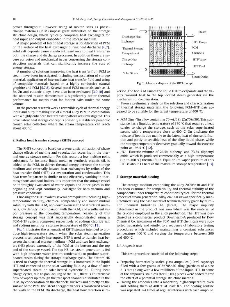
Fig. 1 illustrates the schematic of RHTS storage intended to pro-duce high-temperature steam when the solar steam generationprocess is temporarily interrupted. HTF is used to transfer heat be-tween the thermal storage medium – PCM and two heat exchang-ers (HE) placed externally of the PCM at the bottom and the topand of the storage vessel. The top HE, i.e. steam generator, is fedwith high pressure water (return condensate) to produce super-heated steam during the storage discharge cycle. The bottom HEis used to charge the thermal storage. It is immersed in the liquidHTF and connected to the solar working fluid, e.g. a flow of solarsuperheated steam or solar-heated synthetic oil. During heatcharge cycles, due to pool-boiling of the HTF, there is an intensiveflow of vapors up through the transport channels distributed in thePCM. By condensation on the channels’ surfaces and directly on thesurface of the PCM, the latent energy of vapors is transferred acrossthe walls to the PCM. On discharge, the heat flow direction is re-
versed. The hot PCM causes the liquid HTF to evaporate and the va-pors transmit heat to the top located steam generator via themechanism of condensation.
From a preliminary study on the selection and characterizationof thermal storage materials, the following PCM–HTF pair ap-peared to be suitable for the target temperature of 400 �C:
� PCM: Zinc–Tin alloy containing 70 wt.% Zn (Zn70Sn30). This sub-stance has a liquidus temperature of 370 �C that requires a heatcarrier to charge the storage, such as the solar superheatedsteam, with a temperature close to 400 �C. On discharge therelease of heat is due mainly to the latent heat of zinc solidifica-tion and partly to sensible heat of the alloy liquid phase, whilethe storage temperature decreases gradually toward the eutecticpoint at 198.5 �C [12].
� HTF : Eutectic mixture of 26.5% biphenyl and 73.5% diphenyloxide which is produced commercially as a high-temperature(up to 400 �C) thermal fluid. Equilibrium vapor pressure of thisHTF is about 11 bars at the maximum storage temperature [13].
3. Storage materials testing
The storage medium comprising the alloy Zn70Sn30 and HTFhas been examined for compatibility and thermal stability of thecomponents under temperature conditions typical for the thermalprocess of steam generation. Alloy Zn70Sn30 was specifically man-ufactured using the base metals of technical-purity grade by Numi-nor Chemical Industries Ltd. (Israel). The major impuritydetermined in the product was iron which was the material ofthe crucible employed in the alloy production. The HTF was pur-chased as a commercial product Dowtherm-A produced by DowChemical Co. Specimens of the PCM and HTF chemicals were sub-jected, separately and jointly, to a sequence of laboratory testingprocedures which included maintaining a constant substancestemperature 400 �C and varying the temperature between 200and 400 �C.
3.1. Ampoule tests
This test procedure consisted of the following steps:
� Preparing hermetically sealed glass ampoules (10 ml capacity)filled with a few grams of Zn70Sn30 alloy (particles of a size2–3 mm) along with a few milliliters of the liquid HTF. In someof the ampoules, stainless steel (316L) pieces were added to testthe effect of a potential storage structure material.
� Placing the ampoules into a laboratory high-temperature ovenand holding them at 400 �C at least 8 h. The heating routinewas repeated 3–4 times at regular intervals with each ampoule.
TWater
TInsul
TVessel
TCond
TVapor
TPCM
THTF
TFurnace PVapor
Stirrer
Water-filledCondenser (4L) Insulation
Electric Furnace 200-400oC
Vessel
HTF (450ml): vapor liquid
PCM (1500g)
Metering Valve
HTF Circulation
12
3
Fig. 3. Schematic representation of the lab calorimetric set-up. Points of measure-ments: T-temperature, P-pressure.
R. Adinberg et al. / Energy Conversion and Management 51 (2010) 9–15 11
� Post-test visual inspection of the ampoules at ambient temper-ature for: integrity (some might burst), change of color, physicalstate, additional phases, etc.
� Examining the content of ampoules by means of DifferentialThermal Analysis (TA Instruments TG/DTA Q600 system) andFTIR Spectroscopy (Brukner FTIR Analyzer TENSOR 27).
It is shown in Fig. 2 that some visible changes could be typicallyobserved after the first heating of a test ampoule:
1. The solid particles became fully fused as a result of heatingabove the liquidus point, 370 �C.
2. The liquid, first transparent and colorless, appeared to be yel-lowish-red. This is likely an effect of opalescence caused byreaction of the liquid with air remaining in the ampoule aftersealing. The same change in color occurred when the HTF wassealed in ampoules and heated above 200 �C with no presenceof supplemental materials. This change of color (no differencein the FTIR spectrum could be detected) has no consequenceson the performance of the thermal storage.
3. No further visible modifications of the ampoule contents werediscovered after repeating the heating procedure several times.
About 20 ampoules containing PCM–HTF-Steel samples weretested accordingly. All of them, without exception, showed satis-factory results in terms of thermal stability and compatibility ofthe storage materials. In addition, the remarkable thermal stabilityof the selected PCM–HTF system was verified under continuous30-days heating of the test ampoules at 400 �C.
3.2. Heat cycling tests
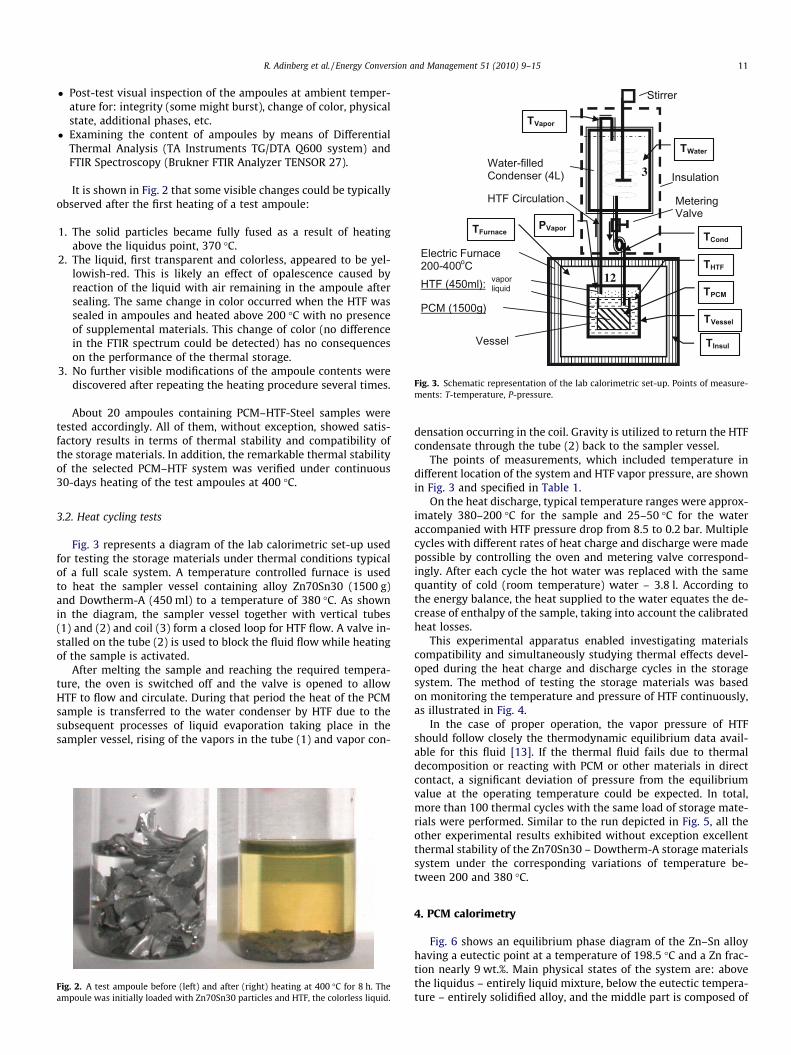
Fig. 3 represents a diagram of the lab calorimetric set-up usedfor testing the storage materials under thermal conditions typicalof a full scale system. A temperature controlled furnace is usedto heat the sampler vessel containing alloy Zn70Sn30 (1500 g)and Dowtherm-A (450 ml) to a temperature of 380 �C. As shownin the diagram, the sampler vessel together with vertical tubes(1) and (2) and coil (3) form a closed loop for HTF flow. A valve in-stalled on the tube (2) is used to block the fluid flow while heatingof the sample is activated.
After melting the sample and reaching the required tempera-ture, the oven is switched off and the valve is opened to allowHTF to flow and circulate. During that period the heat of the PCMsample is transferred to the water condenser by HTF due to thesubsequent processes of liquid evaporation taking place in thesampler vessel, rising of the vapors in the tube (1) and vapor con-
Fig. 2. A test ampoule before (left) and after (right) heating at 400 �C for 8 h. Theampoule was initially loaded with Zn70Sn30 particles and HTF, the colorless liquid.
densation occurring in the coil. Gravity is utilized to return the HTFcondensate through the tube (2) back to the sampler vessel.
The points of measurements, which included temperature indifferent location of the system and HTF vapor pressure, are shownin Fig. 3 and specified in Table 1.
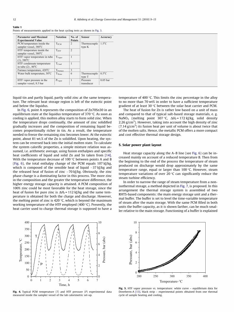
On the heat discharge, typical temperature ranges were approx-imately 380–200 �C for the sample and 25–50 �C for the wateraccompanied with HTF pressure drop from 8.5 to 0.2 bar. Multiplecycles with different rates of heat charge and discharge were madepossible by controlling the oven and metering valve correspond-ingly. After each cycle the hot water was replaced with the samequantity of cold (room temperature) water – 3.8 l. According tothe energy balance, the heat supplied to the water equates the de-crease of enthalpy of the sample, taking into account the calibratedheat losses.
This experimental apparatus enabled investigating materialscompatibility and simultaneously studying thermal effects devel-oped during the heat charge and discharge cycles in the storagesystem. The method of testing the storage materials was basedon monitoring the temperature and pressure of HTF continuously,as illustrated in Fig. 4.
In the case of proper operation, the vapor pressure of HTFshould follow closely the thermodynamic equilibrium data avail-able for this fluid [13]. If the thermal fluid fails due to thermaldecomposition or reacting with PCM or other materials in directcontact, a significant deviation of pressure from the equilibriumvalue at the operating temperature could be expected. In total,more than 100 thermal cycles with the same load of storage mate-rials were performed. Similar to the run depicted in Fig. 5, all theother experimental results exhibited without exception excellentthermal stability of the Zn70Sn30 – Dowtherm-A storage materialssystem under the corresponding variations of temperature be-tween 200 and 380 �C.
4. PCM calorimetry
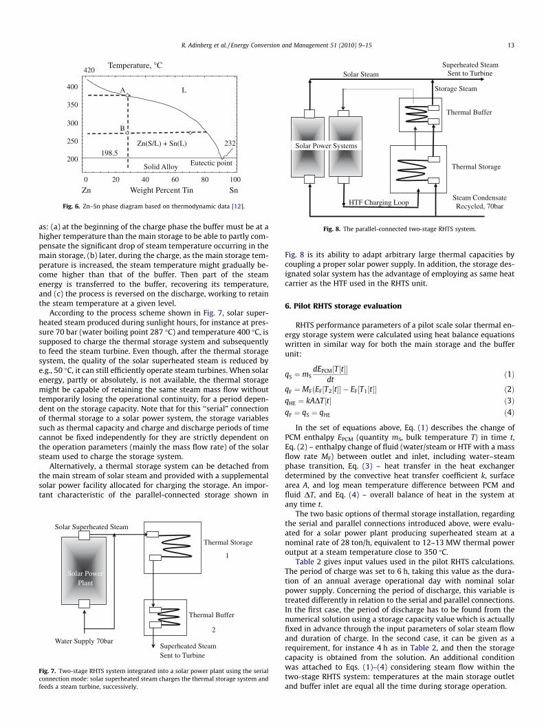
Fig. 6 shows an equilibrium phase diagram of the Zn–Sn alloyhaving a eutectic point at a temperature of 198.5 �C and a Zn frac-tion nearly 9 wt.%. Main physical states of the system are: abovethe liquidus – entirely liquid mixture, below the eutectic tempera-ture – entirely solidified alloy, and the middle part is composed of
Table 1Points of measurements applied in the heat cycling tests as shown in Fig. 3.
12 R. Adinberg et al. / Energy Conversion and Management 51 (2010) 9–15
liquid tin and partly liquid, partly solid zinc at the same tempera-ture. The relevant heat storage region is left of the eutectic pointand below the liquidus.
In Fig. 6, point A represents the composition of Zn70Sn30 in anequilibrium state at the liquidus temperature of 370 �C. As soon ascooling is applied, this molten alloy starts to form solid zinc. Whenthe temperature drops continually, the amount of zinc solidifiedgradually increases and the composition of remaining liquid be-comes proportionally richer in tin. As a result, the temperatureneeded to freeze the remaining zinc becomes lower. At the eutecticpoint, about 81 wt.% of the Zn is solidified. Upon heating, the sys-tem can be reversed back into the initial molten state. To calculatethe system calorific properties, a simple mixture relation was as-sumed, i.e. arithmetic average, using fusion enthalpies and specificheat coefficients of liquid and solid Zn and Sn taken from [14].With the temperature decrease of 100 �C between points A and B(Fig. 6), the total enthalpy change of the PCM equals 107 kJ/kg,which is composed of the sensible heat of liquid �37 kJ/kg andthe released heat of fusion of zinc �70 kJ/kg. Obviously, the zincphase change is a dominating factor in this process. The more zincin the composition and the greater the temperature difference, thehigher energy storage capacity is attained. A PCM composition of100% zinc could be most favorable for the heat storage, since theheat of fusion for pure zinc is DHf = 112 kJ/kg and the same tem-perature is obtained for both the charge and discharge. However,the melting point of zinc is 420 �C, which is beyond the maximumworking temperature of the HTF employed (400 �C). Presently, theheat carrier used to charge thermal storage is supposed to have a
0 1 2 3 4 5 6 70
50
100
150
200
250
300
350
400
P
Pres
sure
, bar
(ab
s)
Tem
pera
ture
, °C
Time, h
T
0
2
4
6
8
10
Fig. 4. Typical PCM temperature (T) and HTF pressure (P) experimental datameasured inside the sampler vessel of the lab calorimetric set-up.
temperature of 400 �C. This limits the zinc percentage in the alloyto no more than 70 wt% in order to have a sufficient temperaturegradient of at least 30 �C between the solar heat carrier and PCM.
The heat of fusion for Zn is rather low based on a unit of massand compared to that of typical salt-based storage materials, e. g.NaNO3 (melting point 307 �C, DHf = 172 kJ/kg, solid density2.26 g/cm3). However, taking into account the high density of zinc(7.14 g/cm3) its fusion heat per unit of volume is about twice thatof the molten salts. Hence, the metallic PCM offers a more compactand cost effective thermal storage design.
5. Solar power plant layout
Heat storage capacity along the A–B line (see Fig. 6) can be in-creased mainly on account of a reduced temperature B. Then fromthe beginning to the end of the process the temperature of steamproduced on discharge would drop approximately by the sametemperature range, equal or larger than 100 �C. However, steamtemperature variations of over 20 �C can significantly reduce thesteam turbine efficiency.
In order to narrow the range of steam temperature from a non-isothermal storage, a method depicted in Fig. 7, is proposed. In thisarrangement the thermal storage system is assembled of twoRHTS-based components: the main energy storage unit and a ther-mal buffer. The buffer is set to level the time-variable temperatureof steam after the main storage. With the same PCM filled in bothunits the buffer capacity, as it is shown farther, can be much smal-ler relative to the main storage. Functioning of a buffer is explained
200 250 300 350 4000
2
4
6
8
10
Pres
sure
, bar
(ab
s)
Temperature-°C
Fig. 5. HTF vapor pressure vs. temperature: white curve – equilibrium data forDowtherm-A [13], black strip – experimental points obtained from one thermalcycle of sample heating and cooling.
Steam Condensate Recycled, 70bar
Thermal Buffer
Thermal Storage
Superheated SteamSent to Turbine
HTF Charging Loop
Solar Steam
Storage Steam
Solar Power Systems
Fig. 8. The parallel-connected two-stage RHTS system.
0 20 40 60 80 100
200
250
300
350
400
Temperature, °C
SnWeight Percent TinZn
Zn(S/L) + Sn(L)
L
Eutectic pointSolid Alloy
198.5232
420
A
B
Fig. 6. Zn–Sn phase diagram based on thermodynamic data [12].
R. Adinberg et al. / Energy Conversion and Management 51 (2010) 9–15 13
as: (a) at the beginning of the charge phase the buffer must be at ahigher temperature than the main storage to be able to partly com-pensate the significant drop of steam temperature occurring in themain storage, (b) later, during the charge, as the main storage tem-perature is increased, the steam temperature might gradually be-come higher than that of the buffer. Then part of the steamenergy is transferred to the buffer, recovering its temperature,and (c) the process is reversed on the discharge, working to retainthe steam temperature at a given level.
According to the process scheme shown in Fig. 7, solar super-heated steam produced during sunlight hours, for instance at pres-sure 70 bar (water boiling point 287 �C) and temperature 400 �C, issupposed to charge the thermal storage system and subsequentlyto feed the steam turbine. Even though, after the thermal storagesystem, the quality of the solar superheated steam is reduced bye.g., 50 �C, it can still efficiently operate steam turbines. When solarenergy, partly or absolutely, is not available, the thermal storagemight be capable of retaining the same steam mass flow withouttemporarily losing the operational continuity, for a period depen-dent on the storage capacity. Note that for this ‘‘serial” connectionof thermal storage to a solar power system, the storage variablessuch as thermal capacity and charge and discharge periods of timecannot be fixed independently for they are strictly dependent onthe operation parameters (mainly the mass flow rate) of the solarsteam used to charge the storage system.
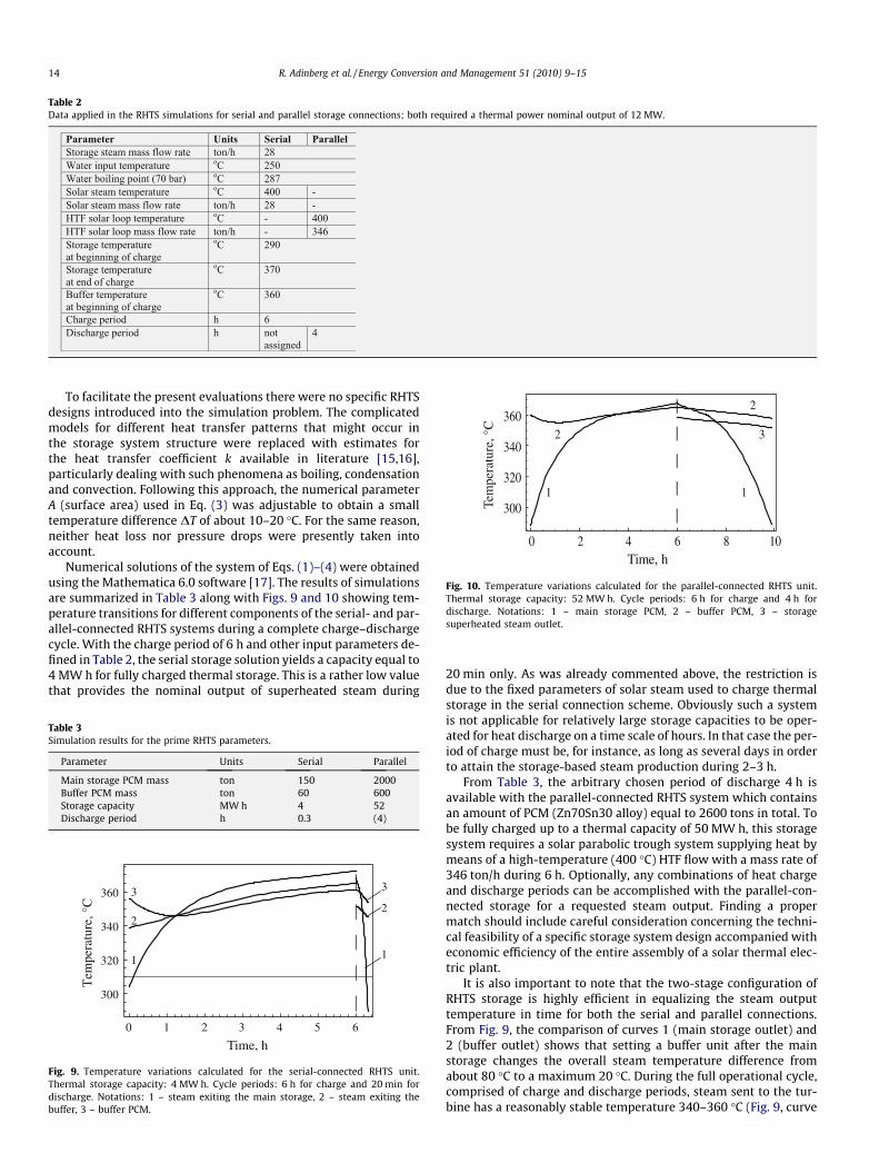
Alternatively, a thermal storage system can be detached fromthe main stream of solar steam and provided with a supplementalsolar power facility allocated for charging the storage. An impor-tant characteristic of the parallel-connected storage shown in
Solar Power Plant
Thermal Buffer
Solar Superheated Steam
Superheated SteamSent to Turbine
Water Supply 70bar
Thermal Storage
1
2
Fig. 7. Two-stage RHTS system integrated into a solar power plant using the serialconnection mode: solar superheated steam charges the thermal storage system andfeeds a steam turbine, successively.
Fig. 8 is its ability to adapt arbitrary large thermal capacities bycoupling a proper solar power supply. In addition, the storage des-ignated solar system has the advantage of employing as same heatcarrier as the HTF used in the RHTS unit.
6. Pilot RHTS storage evaluation
RHTS performance parameters of a pilot scale solar thermal en-ergy storage system were calculated using heat balance equationswritten in similar way for both the main storage and the bufferunit:
In the set of equations above, Eq. (1) describes the change ofPCM enthalpy EPCM (quantity mS, bulk temperature T) in time t,Eq. (2) – enthalpy change of fluid (water/steam or HTF with a massflow rate MF) between outlet and inlet, including water–steamphase transition, Eq. (3) – heat transfer in the heat exchangerdetermined by the convective heat transfer coefficient k, surfacearea A, and log mean temperature difference between PCM andfluid DT, and Eq. (4) – overall balance of heat in the system atany time t.
The two basic options of thermal storage installation, regardingthe serial and parallel connections introduced above, were evalu-ated for a solar power plant producing superheated steam at anominal rate of 28 ton/h, equivalent to 12–13 MW thermal poweroutput at a steam temperature close to 350 �C.
Table 2 gives input values used in the pilot RHTS calculations.The period of charge was set to 6 h, taking this value as the dura-tion of an annual average operational day with nominal solarpower supply. Concerning the period of discharge, this variable istreated differently in relation to the serial and parallel connections.In the first case, the period of discharge has to be found from thenumerical solution using a storage capacity value which is actuallyfixed in advance through the input parameters of solar steam flowand duration of charge. In the second case, it can be given as arequirement, for instance 4 h as in Table 2, and then the storagecapacity is obtained from the solution. An additional conditionwas attached to Eqs. (1)–(4) considering steam flow within thetwo-stage RHTS system: temperatures at the main storage outletand buffer inlet are equal all the time during storage operation.
Table 2Data applied in the RHTS simulations for serial and parallel storage connections; both required a thermal power nominal output of 12 MW.
0 2 4 6 8 10
300
320
340
360
1
2 3
2
1
Time, h
Tem
pera
ture
, °C
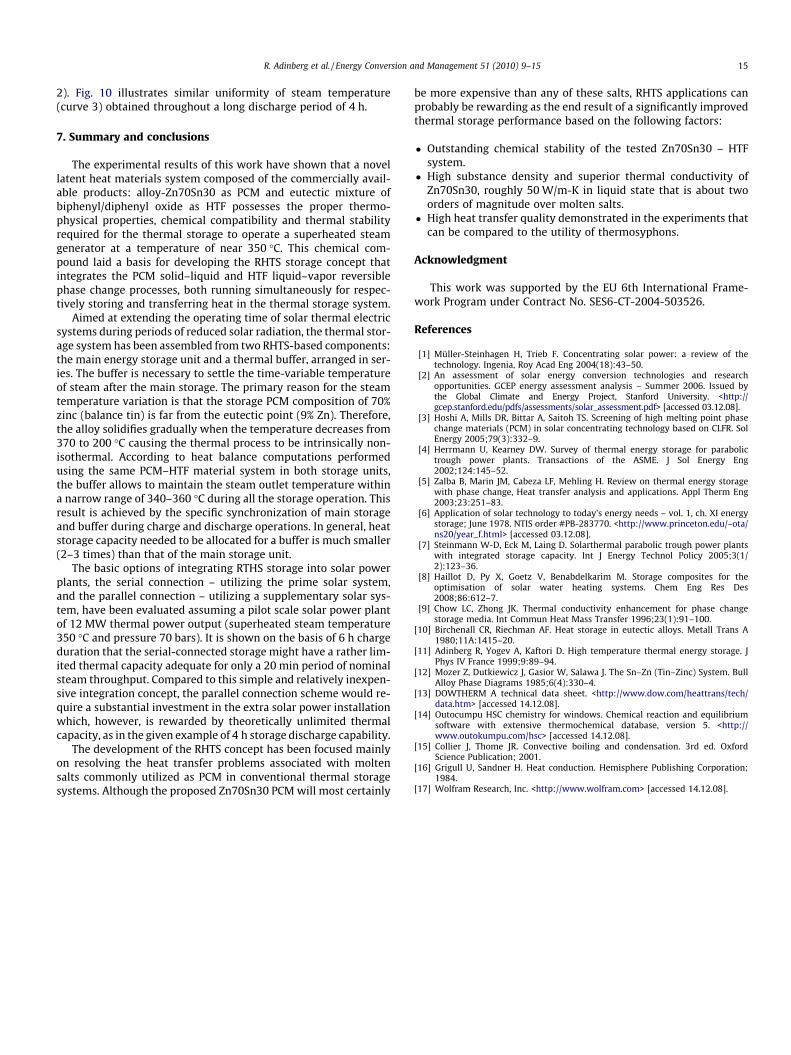
Fig. 10. Temperature variations calculated for the parallel-connected RHTS unit.Thermal storage capacity: 52 MW h. Cycle periods: 6 h for charge and 4 h fordischarge. Notations: 1 – main storage PCM, 2 – buffer PCM, 3 – storagesuperheated steam outlet.
14 R. Adinberg et al. / Energy Conversion and Management 51 (2010) 9–15
To facilitate the present evaluations there were no specific RHTSdesigns introduced into the simulation problem. The complicatedmodels for different heat transfer patterns that might occur inthe storage system structure were replaced with estimates forthe heat transfer coefficient k available in literature [15,16],particularly dealing with such phenomena as boiling, condensationand convection. Following this approach, the numerical parameterA (surface area) used in Eq. (3) was adjustable to obtain a smalltemperature difference DT of about 10–20 �C. For the same reason,neither heat loss nor pressure drops were presently taken intoaccount.
Numerical solutions of the system of Eqs. (1)–(4) were obtainedusing the Mathematica 6.0 software [17]. The results of simulationsare summarized in Table 3 along with Figs. 9 and 10 showing tem-perature transitions for different components of the serial- and par-allel-connected RHTS systems during a complete charge–dischargecycle. With the charge period of 6 h and other input parameters de-fined in Table 2, the serial storage solution yields a capacity equal to4 MW h for fully charged thermal storage. This is a rather low valuethat provides the nominal output of superheated steam during
Table 3Simulation results for the prime RHTS parameters.
Parameter Units Serial Parallel
Main storage PCM mass ton 150 2000Buffer PCM mass ton 60 600Storage capacity MW h 4 52Discharge period h 0.3 (4)
Time, h0 1 2 3 4 5 6
300
320
340
360 3
2
1
3
2
1
Tem
pera
ture
, °C
Fig. 9. Temperature variations calculated for the serial-connected RHTS unit.Thermal storage capacity: 4 MW h. Cycle periods: 6 h for charge and 20 min fordischarge. Notations: 1 – steam exiting the main storage, 2 – steam exiting thebuffer, 3 – buffer PCM.
20 min only. As was already commented above, the restriction isdue to the fixed parameters of solar steam used to charge thermalstorage in the serial connection scheme. Obviously such a systemis not applicable for relatively large storage capacities to be oper-ated for heat discharge on a time scale of hours. In that case the per-iod of charge must be, for instance, as long as several days in orderto attain the storage-based steam production during 2–3 h.
From Table 3, the arbitrary chosen period of discharge 4 h isavailable with the parallel-connected RHTS system which containsan amount of PCM (Zn70Sn30 alloy) equal to 2600 tons in total. Tobe fully charged up to a thermal capacity of 50 MW h, this storagesystem requires a solar parabolic trough system supplying heat bymeans of a high-temperature (400 �C) HTF flow with a mass rate of346 ton/h during 6 h. Optionally, any combinations of heat chargeand discharge periods can be accomplished with the parallel-con-nected storage for a requested steam output. Finding a propermatch should include careful consideration concerning the techni-cal feasibility of a specific storage system design accompanied witheconomic efficiency of the entire assembly of a solar thermal elec-tric plant.
It is also important to note that the two-stage configuration ofRHTS storage is highly efficient in equalizing the steam outputtemperature in time for both the serial and parallel connections.From Fig. 9, the comparison of curves 1 (main storage outlet) and2 (buffer outlet) shows that setting a buffer unit after the mainstorage changes the overall steam temperature difference fromabout 80 �C to a maximum 20 �C. During the full operational cycle,comprised of charge and discharge periods, steam sent to the tur-bine has a reasonably stable temperature 340–360 �C (Fig. 9, curve
R. Adinberg et al. / Energy Conversion and Management 51 (2010) 9–15 15
2). Fig. 10 illustrates similar uniformity of steam temperature(curve 3) obtained throughout a long discharge period of 4 h.
7. Summary and conclusions
The experimental results of this work have shown that a novellatent heat materials system composed of the commercially avail-able products: alloy-Zn70Sn30 as PCM and eutectic mixture ofbiphenyl/diphenyl oxide as HTF possesses the proper thermo-physical properties, chemical compatibility and thermal stabilityrequired for the thermal storage to operate a superheated steamgenerator at a temperature of near 350 �C. This chemical com-pound laid a basis for developing the RHTS storage concept thatintegrates the PCM solid–liquid and HTF liquid–vapor reversiblephase change processes, both running simultaneously for respec-tively storing and transferring heat in the thermal storage system.
Aimed at extending the operating time of solar thermal electricsystems during periods of reduced solar radiation, the thermal stor-age system has been assembled from two RHTS-based components:the main energy storage unit and a thermal buffer, arranged in ser-ies. The buffer is necessary to settle the time-variable temperatureof steam after the main storage. The primary reason for the steamtemperature variation is that the storage PCM composition of 70%zinc (balance tin) is far from the eutectic point (9% Zn). Therefore,the alloy solidifies gradually when the temperature decreases from370 to 200 �C causing the thermal process to be intrinsically non-isothermal. According to heat balance computations performedusing the same PCM–HTF material system in both storage units,the buffer allows to maintain the steam outlet temperature withina narrow range of 340–360 �C during all the storage operation. Thisresult is achieved by the specific synchronization of main storageand buffer during charge and discharge operations. In general, heatstorage capacity needed to be allocated for a buffer is much smaller(2–3 times) than that of the main storage unit.
The basic options of integrating RTHS storage into solar powerplants, the serial connection – utilizing the prime solar system,and the parallel connection – utilizing a supplementary solar sys-tem, have been evaluated assuming a pilot scale solar power plantof 12 MW thermal power output (superheated steam temperature350 �C and pressure 70 bars). It is shown on the basis of 6 h chargeduration that the serial-connected storage might have a rather lim-ited thermal capacity adequate for only a 20 min period of nominalsteam throughput. Compared to this simple and relatively inexpen-sive integration concept, the parallel connection scheme would re-quire a substantial investment in the extra solar power installationwhich, however, is rewarded by theoretically unlimited thermalcapacity, as in the given example of 4 h storage discharge capability.
The development of the RHTS concept has been focused mainlyon resolving the heat transfer problems associated with moltensalts commonly utilized as PCM in conventional thermal storagesystems. Although the proposed Zn70Sn30 PCM will most certainly
be more expensive than any of these salts, RHTS applications canprobably be rewarding as the end result of a significantly improvedthermal storage performance based on the following factors:
� Outstanding chemical stability of the tested Zn70Sn30 – HTFsystem.
� High substance density and superior thermal conductivity ofZn70Sn30, roughly 50 W/m-K in liquid state that is about twoorders of magnitude over molten salts.
� High heat transfer quality demonstrated in the experiments thatcan be compared to the utility of thermosyphons.
Acknowledgment
This work was supported by the EU 6th International Frame-work Program under Contract No. SES6-CT-2004-503526.
References
[1] Müller-Steinhagen H, Trieb F. Concentrating solar power: a review of thetechnology. Ingenia, Roy Acad Eng 2004(18):43–50.
[2] An assessment of solar energy conversion technologies and researchopportunities. GCEP energy assessment analysis – Summer 2006. Issued bythe Global Climate and Energy Project, Stanford University. <http://gcep.stanford.edu/pdfs/assessments/solar_assessment.pdf> [accessed 03.12.08].
[3] Hoshi A, Mills DR, Bittar A, Saitoh TS. Screening of high melting point phasechange materials (PCM) in solar concentrating technology based on CLFR. SolEnergy 2005;79(3):332–9.
[4] Herrmann U, Kearney DW. Survey of thermal energy storage for parabolictrough power plants. Transactions of the ASME. J Sol Energy Eng2002;124:145–52.
[5] Zalba B, Marin JM, Cabeza LF, Mehling H. Review on thermal energy storagewith phase change, Heat transfer analysis and applications. Appl Therm Eng2003;23:251–83.
[6] Application of solar technology to today’s energy needs – vol. 1, ch. XI energystorage; June 1978. NTIS order #PB-283770. <http://www.princeton.edu/~ota/ns20/year_f.html> [accessed 03.12.08].
[7] Steinmann W-D, Eck M, Laing D. Solarthermal parabolic trough power plantswith integrated storage capacity. Int J Energy Technol Policy 2005;3(1/2):123–36.
[8] Haillot D, Py X, Goetz V, Benabdelkarim M. Storage composites for theoptimisation of solar water heating systems. Chem Eng Res Des2008;86:612–7.
[9] Chow LC, Zhong JK. Thermal conductivity enhancement for phase changestorage media. Int Commun Heat Mass Transfer 1996;23(1):91–100.
[10] Birchenall CR, Riechman AF. Heat storage in eutectic alloys. Metall Trans A1980;11A:1415–20.
[11] Adinberg R, Yogev A, Kaftori D. High temperature thermal energy storage. JPhys IV France 1999;9:89–94.
[12] Mozer Z, Dutkiewicz J, Gasior W, Salawa J. The Sn–Zn (Tin–Zinc) System. BullAlloy Phase Diagrams 1985;6(4):330–4.
[13] DOWTHERM A technical data sheet. <http://www.dow.com/heattrans/tech/data.htm> [accessed 14.12.08].
[14] Outocumpu HSC chemistry for windows. Chemical reaction and equilibriumsoftware with extensive thermochemical database, version 5. <http://www.outokumpu.com/hsc> [accessed 14.12.08].
[15] Collier J, Thome JR. Convective boiling and condensation. 3rd ed. OxfordScience Publication; 2001.
[16] Grigull U, Sandner H. Heat conduction. Hemisphere Publishing Corporation;1984.
[17] Wolfram Research, Inc. <http://www.wolfram.com> [accessed 14.12.08].