74
1 HEAT TRANSFAR LAB MANUAL 2015- 16 HEAT TRANSFER LAB MANUAL

1
HEAT TRANSFAR LAB MANUAL 2015- 16
HEAT TRANSFER LAB MANUAL

2
LIST OF EXPERIMENTS
SN NAME OF THE EXPERIMENT
1 HEAT TRANSFER THROUGH COMPOSITE WALL
2 CRITICAL HEAT FLUX APPARATUS
3 MEASUREMENT OF SURFACE EMMISSIVITY
4 HEAT TRANSFER THROUGH FORCED CONVECTION
5 HEAT TRANSFER THROUGH LAGGED PIPE
6 HEAT TRANSFER THROUGH NATURAL CONVECTION
7 PARALLEL & COUNTER FLOW HEAT EXCHANGER
8 HEAT TRANSFER THROUGH PIN – FIN
9 STEFAN BOLTZMAN’S APPARATUS
10 THERMAL CONDUCTIVITY OF CONCENTRIC SPHERE
11 THERMAL CONDUCTIVITY OF METAL ROD
12 TRANSIENT HEAT CONDUCTION APPARATUS
13 HEAT PIPE DEMONSTRATION
HEAT TRANSFAR LAB MANUAL 2015- 16

3
HEAT TRANSFER THROUGH
COMPOSITE WALL
INTRODUCTION:
In engineering applications, we deal with many problems. Heat
Transfer through composite walls is one of them. It is the transport of
energy between two or more bodies of different thermal conductivity
arranged in series or parallel. For example, a fastener joining two
mediums also acts as one of the layers between these mediums.
Hence, the thermal conductivity of the fastener is also very much
necessary in determining the overall heat transfer through the
medium. An attempt has been made to show the concept of heat
transfers through composite walls.
DESCRIPTION OF THE APPARATUS:
The apparatus consists of three slabs of Mild Steel, Bakelite
and Aluminum materials of thickness 25, 20 & 12mm respectively
clamped in the center using screw rod.
At the center of the composite wall a heater is fitted. End
losses from the composite wall are minimized by providing thick
insulation all round to ensure unidirectional heat flow.
Front transparent acrylic enclosure to minimize the
disturbances of the surrounding and also for safety of the tube when
not in use.
Control panel instrumentation consists of:
HEAT TRANSFAR LAB MANUAL 2015- 16
4
a. Digital Temperature Indicator with channel selector.
b. Digital Voltmeter & Ammeter for power
measurement.
c. Heater regulator to regulate the input power.
With this the whole arrangement is mounted on an aesthetically
designed self-sustained MS powder coated frame with a separate
control panel.
EXPERIMENTATION:
AIM: To determine
1. The overall thermal conductance (C) for a composite wall and
to compare with theoretical value.
2. Temperature distribution across the width of the composite
wall.
PROCEDURE:
1. Symmetrically arrange the plates and ensure perfect contact
between the plates.
2. Switch ON mains and the CONSOLE.
3. Set the heater regulator to the known value.
4. Wait for sufficient time to allow temperature to reach steady
values.
5. Note down the Temperatures 1 to 7 using the channel selector
and digital temperature indicator.
6. Note down the ammeter and voltmeter readings.
HEAT TRANSFAR LAB MANUAL 2015- 16
5
7. Calculate the overall conductance using the procedure given
below.
8. Repeat the experiment for different heat input.
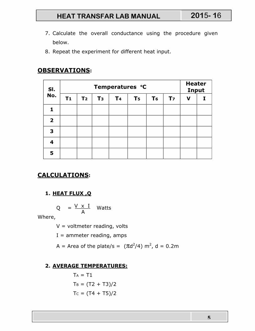
OBSERVATIONS:
Sl. No.
Temperatures °°°°C Heater Input
T1 T2 T3 T4 T5 T6 T7 V I
1
2
3
4
5
CALCULATIONS:
1. HEAT FLUX ,Q
Q = Watts
Where,
V = voltmeter reading, volts
I = ammeter reading, amps
A = Area of the plate/s = (πd2/4) m2, d = 0.2m
2. AVERAGE TEMPERATURES:
TA = T1
TB = (T2 + T3)/2
TC = (T4 + T5)/2
V x I
A
HEAT TRANSFAR LAB MANUAL 2015- 16
6
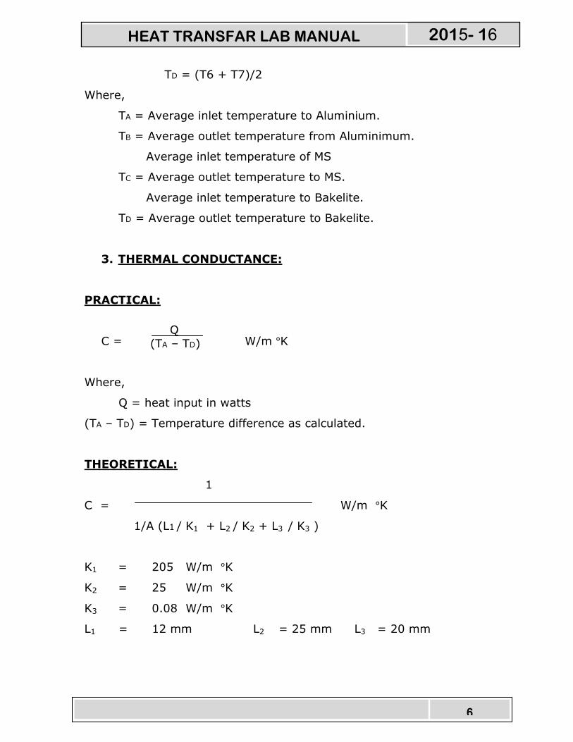
TD = (T6 + T7)/2
Where,
TA = Average inlet temperature to Aluminium.
TB = Average outlet temperature from Aluminimum.
Average inlet temperature of MS
TC = Average outlet temperature to MS.
Average inlet temperature to Bakelite.
TD = Average outlet temperature to Bakelite.
3. THERMAL CONDUCTANCE:
PRACTICAL:
C = W/m °K
Where,
Q = heat input in watts
(TA – TD) = Temperature difference as calculated.
THEORETICAL:
1
C = W/m °K
1/A (L1 / K1 + L2 / K2 + L3 / K3 )
K1 = 205 W/m °K
K2 = 25 W/m °K
K3 = 0.08 W/m °K
L1 = 12 mm L2 = 25 mm L3 = 20 mm
Q (TA – TD)
HEAT TRANSFAR LAB MANUAL 2015- 16

7
4. OVERALL THERMAL CONDUCTIVITY OF THE SLAB, K
K = W/m °K
Where, B = thickness of the plates on one side = 0.057m
5. PLOT TEMPERATURE DISTRIBUTION CURVE
Reference:
1. Heat and Mass transfer by Arora & Domkundwar
2. Chemical Engineers’ Handbook, by Robert H. Perry / Cecil H. Chilton
Publication: McGraw – Hill Book Company (6th edition)
PRECAUTIONS: 1. Check all the electrical connections.
2. Do not run the equipment if the voltage is below 180V.
3. Do not attempt to alter the equipment as this may cause
damage to the whole system.
Q x B
(TA – TD)
HEAT TRANSFAR LAB MANUAL 2015- 16

8
CRITICAL HEAT FLUX APPARATUS
1. INTRODUCTION:
Boiling and Condensation are the specific convection processes
which is associated with change of phase. The co – efficient of heat
transfer are correspondingly very high when compared to natural
conventional process while the accompanying temperature difference
are small (quite).
However, the visualization of this mode of heat transfer is more
difficult and the actual solutions are still difficult than conventional
heat transfer process.
Commonly, this mode of heat transfer with change of phase is
seen in Boilers, condensers in power plants and evaporators in
refrigeration system.
2. DESCRIPTION OF APPARATUS:
� The apparatus consists of a specially designed Glass
Cylinder.
� An arrangement above the Cylinder in the form of Bakelite
plate is provided to place the main Heater and the Nichrome
wire heater arrangement.
� The base is made of MS and is powder coated with Rubber
cushion to place the Glass cylinder.
� Heater regulator to supply the regulated power input to the
heater.
HEAT TRANSFAR LAB MANUAL 2015- 16
9
� Digital Voltmeter and Ammeter to measure poser input ot the
heater.
� Thermocouples at suitable position to measure the temperatures
of body and the air.
� Digital Temperature Indicator with channel selector to measure
the temperatures.
� The whole arrangement is mounted on an Aesthetically
designed sturdy frame made of MS tubes and NOVAPAN Board
with all the provisions for holding the tanks and accessories.
3. EXPERIMENTATION:
i. AIM:
� To observe the formation of pool boiling and
� To draw the graph of heat flux Vs. Bulk Temperature
upto Burnout (Critical) condition.
ii. PROCEDURE:
1. Fill in the Glass Cylinder with Distilled Water above
the heater level.
2. Connect the Nichrome Wire (Test Wire) of suitable length.
3. Keep the heater regulator to the minimum position.
4. Connect the power cable to 1Ph, 220V, 10 Amps with earth connection.
5. Switch on the Mains On to activate the control panel.
HEAT TRANSFAR LAB MANUAL 2015- 16
10
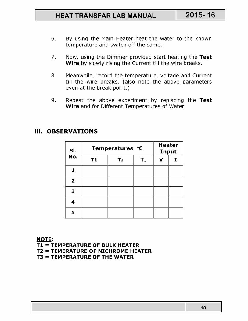
6. By using the Main Heater heat the water to the known temperature and switch off the same.
7. Now, using the Dimmer provided start heating the Test
Wire by slowly rising the Current till the wire breaks.
8. Meanwhile, record the temperature, voltage and Current
till the wire breaks. (also note the above parameters even at the break point.)
9. Repeat the above experiment by replacing the Test Wire and for Different Temperatures of Water.
iii. OBSERVATIONS
Sl.
No.
Temperatures °°°°C Heater
Input
T1 T2 T3 V I
1
2
3
4
5
NOTE: T1 = TEMPERATURE OF BULK HEATER
T2 = TEMERATURE OF NICHROME HEATER T3 = TEMPERATURE OF THE WATER
HEAT TRANSFAR LAB MANUAL 2015- 16
11
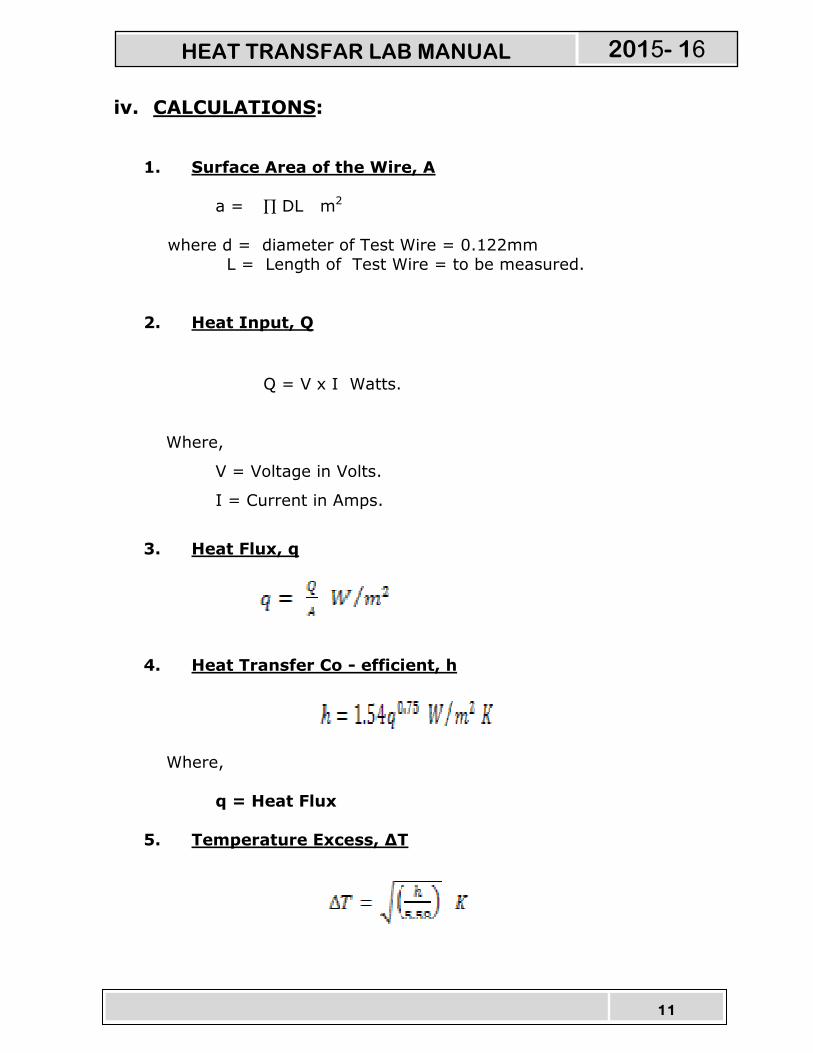
iv. CALCULATIONS:
1. Surface Area of the Wire, A
a = ∏ DL m2
where d = diameter of Test Wire = 0.122mm L = Length of Test Wire = to be measured.
2. Heat Input, Q
Q = V x I Watts.
Where,
V = Voltage in Volts.
I = Current in Amps.
3. Heat Flux, q
4. Heat Transfer Co - efficient, h
Where,
q = Heat Flux
5. Temperature Excess, ∆T
HEAT TRANSFAR LAB MANUAL 2015- 16

12
v. TABULAR COLUMN
Sl
No
Heat Flux,
q
Temperature
Excess, ∆T
vi. RESULTS:
� Draw the Graph of q vs. ∆T and
� Compare ∆T with the experimental Values i.e.,
(Difference of Water Temperature and the Test Wire/Boiling
Temperature)
4. PRECAUTIONS
1) Clean the tank regularly after every use.
2) Do not run the equipment if the voltage is below 180V.
3) Check all the electrical connections before running.
4) Do not attempt to alter the equipment as this may cause
damage to the whole system.
HEAT TRANSFAR LAB MANUAL 2015- 16
13
MEASUREMENT OF SURFACE
EMMISSIVITY
INTRODUCTION:
Radiation is one of the modes of heat transfer, which does not
require any material medium for its propagation. All bodies can emit
radiation & have also the capacity to absorb all or a part of the
radiation coming from the surrounding towards it. The mechanism is
assumed to be electromagnetic in nature and is a result of
temperature difference. Thermodynamic considerations show that an
ideal radiator or black body will emit energy at a rate proportional to
the fourth power of the absolute temperature of the body. Other types
of surfaces such as glossy painted surface or a polished metal plate do
not radiate as much energy as the black body , however the total
radiation emitted by these bodies still generally follow the fourth
power proportionality. To take account of the gray nature of such
surfaces, the factor called emmissivity (εεεε), which relates the radiation
of the gray surface to that of an ideal black surface, is used. The
emissivity of the surface is the ratio of the emissive power of the
surface to the emissive power of the black surface at the same
temperature. Emissivity is the property of the surface and depends
upon the nature of the surface and temperature.
HEAT TRANSFAR LAB MANUAL 2015- 16
14
DESCRIPTION OF THE APPARATUS:
The setup consists of a 200mm dia two aluminium plates
one surface blackened to get the effect of the black body and other is
platened to give the effect of the gray body. Both the plates with mica
heaters are mounted on the ceramic base covered with chalk powder
for maximum heat transfer. Two Thermocouples are mounted on their
surfaces to measure the temperatures of the surface and one more to
measure the enclosure/ambient temperature. This complete
arrangement is fixed in an acrylic chamber for visualization.
Temperatures are indicated on the digital temperature indicator with
channel selector to select the temperature point. Heater regulators
are provided to control and monitor the heat input to the system with
voltmeter and ammeter for direct measurement of the heat inputs.
The heater controller is made of complete aluminium body having
fuse.
With this, the setup is mounted on an aesthetically designed
frame with control panel to monitor all the processes. The control
panel consists of mains on indicator, Aluminium body heater
controllers, change over switches, digital temperature indicator with
channel selector, digital voltmeter and ammeter for measurement of
power and other necessary instrumentation. The whole arrangement is
on the single bench considering all safety and aesthetics factors.
HEAT TRANSFAR LAB MANUAL 2015- 16

15
EXPERIMENTATION:
AIM:
The experiment is conducted to determine the emmissivity of the
non – black surface and compare with the black body.
PROCEDURE:
1. Give necessary electrical connections and switch on the MCB and
switch on the console on to activate the control panel.
2. Switch On the heater of the Gray body and set the voltage (say
45V) using the heater regulator and digital voltmeter.
3. Switch On the heater of the Black body and set the voltage or
current (say higher than gray body) using the heater regulator
and digital voltmeter.
4. Wait to attain the steady state.
5. Note down the temperatures at different points and also the
voltmeter and ammeter readings.
6. Tabulate the readings and calculate the surface emmissivity of
the non – black surface.
HEAT TRANSFAR LAB MANUAL 2015- 16

16
QG (TB - TA )
QB (TG - TA )
4
4
4
4
OBSERVATIONS:
Sl.
No.
Heater input Temperature, °C
Black body Gray body
Voltag
e, ‘v’
volts
Curren
t
‘I’
amps
Voltag
e ‘v’
volts
Curren
t
‘I’
amps
T1 T2 T3 T4 T5
1
2
3
4
5
ALTERNATE CALCULATIONS:
1. HEAT INPUT TO THE BLACK BODY, QB
QB = V x I Watts.
2. HEAT INPUT TO THE GRAY BODY, QG
QG = V x I Watts.
3. EMMISSIVITY OF THE GRAY BODY, εεεεG
εεεεG =
QG = Heat input to the gray body.
4
HEAT TRANSFAR LAB MANUAL 2015- 16
17
QB = Heat input to the black body.
A = Area of plates = (πd2/4) m2, d = 0.2m
TB = Temperature of black body = (T1+T2)/2
TG = (T3+T4)/2
TA = Ambient temperature = T5
4. RESULT , εεεεG
The emmissivity of the gray body is εεεεG = ________. Reference:
3. Heat and Mass transfer by Arora & Domkundwar 4. Chemical Engineers’ Handbook, by Robert H. Perry / Cecil H. Chilton Publication: McGraw – Hill Book Company (6th edition)
PRECAUTIONS:
4. Check all the electrical connections.
5. Do not run the equipment if the voltage is below 180V.
6. Make sure that heater regulator is at the minimum position
before switching on the console.
7. After finishing the experiment open the acrylic door to remove
the heat from the chamber.
8. Do not attempt to alter the equipment as this may cause
damage to the whole system.
HEAT TRANSFAR LAB MANUAL 2015- 16
18
HEAT TRANSFER THROUGH
FORCED CONVECTION
INTRODUCTION: Heat transfer can be defined as the transmission of
energy from one region to another as a result of temperature
difference between them. There are three different modes of
heat transfer; namely,
HEAT CONDUCTION : The property which allows the passage
for heat energy, even though its parts
are not in motion relative to one
another.
HEAT CONVECTION : The capacity of moving matter to carry
heat energy by actual movement.
HEAT RADIATION : The property of matter to emit or to
absorb different kinds of radiation by
electromagnetic waves.
Out of these types of heat transfer the convective
heat transfer which of our present concern, divides into two
catagories, Viz.,
NATURAL CONVECTION : If the motion of fluid is caused only
due to difference in density resulting
from temperature gradients without the
use of pump or fan, then the
HEAT TRANSFAR LAB MANUAL 2015- 16
19
mechanism of heat transfer is known as
“Natural or Free Convection”.
FORCED CONVECTION : If the motion of fluid is induced by
some external means such as a pump
or blower, then the heat transfer
process is known as “Forced Convection”.
The newtons law of cooling in convective heat transfer is
given by,
q = h A T Where, q = Heat transfer rate, in watts
A = Surface area of heat flow, in m2
T = Overall temperature difference between the
wall and fluid, in oC
h = Convection heat transfer co-efficient, in
watts/m2 oC
This set up has been designed to study heat transfer by forced
convection.
DESCRIPTION OF THE APPARATUS:
The apparatus consists of
Heat exchanger tube made of copper which is thermally
insulated outside to prevent heat transfer losses to the atmosphere.
Band heaters of 500watts capacity.
Heater regulator to supply the regulated power input to the heater.
Digital Voltmeter and Ammeter to measure poser input ot the
heater.
HEAT TRANSFAR LAB MANUAL 2015- 16
20
Thermocouples at suitable position to measure the
temperatures of body and the air.
Digital Temperature Indicator with channel selector to
measure the temperatures.
Blower unit to blow air through the heat exchanger with orifice
meter and manometer to measure the air flow rate from the blower. A
control valve is provided to regulate the air flow.
Control panel to house all the instrumentation.
With this the whole arrangement is mounted on an aesthetically
designed self-sustained MS powder coated frame with a separate
NOVAPAN Board control panel.
EXPERIMENTATION:
AIM: To determine convective heat transfer coefficient in forced convection.
PROCEDURE:
1. Switch on the MCB and then console on switch to activate the
control panel.
2. Switch on the blower unit first and adjust the flow of air using
wheel valve of blower to a desired difference in manometer.
3. Switch on the heater and set the voltage (say 80V) using the
heater regulator and digital voltmeter.
HEAT TRANSFAR LAB MANUAL 2015- 16
21
4. Wait for reasonable time to allow temperatures to reach steady
state.
5. Measure the voltage, current and temperatures from T1 to T6 at
known time interval.
6. Calculate the convective heat transfer co-efficient using the
procedure given.
7. Repeat the experiment for different values of power input to the
heater and blower air flow rates.
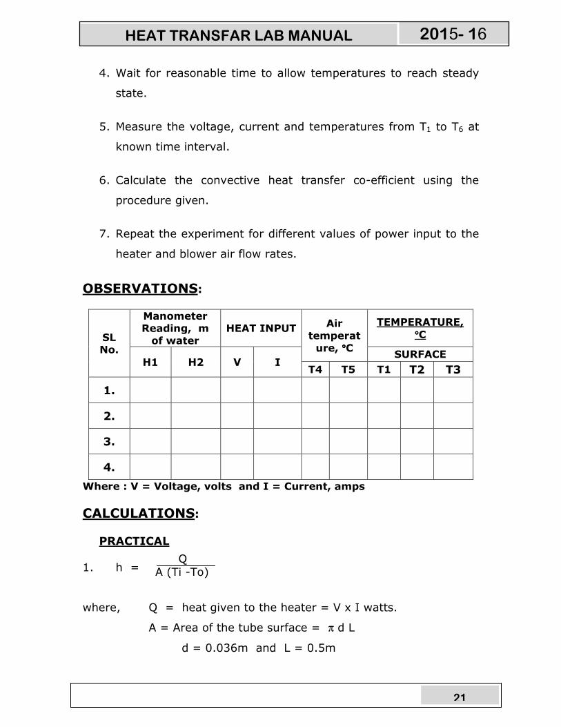
OBSERVATIONS:
SL No.
Manometer Reading, m
of water
HEAT INPUT Air
temperat
ure, °°°°C
TEMPERATURE,
°°°°C
H1 H2 V I SURFACE
T4 T5 T1 T2 T3
1.
2.
3.
4.
Where : V = Voltage, volts and I = Current, amps
CALCULATIONS:
PRACTICAL
1. h =
where, Q = heat given to the heater = V x I watts.
A = Area of the tube surface = π d L
d = 0.036m and L = 0.5m
Q A (Ti -To)
HEAT TRANSFAR LAB MANUAL 2015- 16

22
Ti = mean temperature = (T1+T2+T3)/3
To = . (T4+T5)/2
THEORETICAL
h = (0.023 x Pr x Re x k) / D
Where,
ρVD
Re = -----------
µ
where ,
D = inner diameter of the tube = 0.036
V = m/s
Mass flow rate of air is calculated as follows:
= 0.62 x a x 2gH
where, a = , d= 0.015
H = (H1 ~ H2)x 1000 m of air column
Flow area is calculated as follows:
= , D= 0.036
All the properties of air should be taken at (Ti + To)/2 from the data
hand book.
RESULT:
0.4 0.8
µ Cp
Pr = ---------
K
mass flow rate of air Flow area
π d²
4
1.293
π D²
4
HEAT TRANSFAR LAB MANUAL 2015- 16
23
Draw the graph of ‘h’ versus ‘Tm’ for theoretical and practical
calculations and compare the results.
Reference:
5. Heat and Mass transfer by Arora & Domkundwar 6. Chemical Engineers’ Handbook, by Robert H. Perry / Cecil H. Chilton Publication: McGraw – Hill Book Company (6th edition)
PRECAUTIONS:
9. Check all the electrical connections.
10. Do not run the equipment if the voltage is below 180V.
11. Do not obstruct flow of air while experiment is going on.
12. Make sure that heater regulator is at the minimum position
before switching on the console.
13. Do not attempt to alter the equipment as this may cause
damage to the whole system.
HEAT TRANSFAR LAB MANUAL 2015- 16
24
HEAT TRANSFER THROUGH
LAGGED PIPE
INTRODUCTION:
The costs involved in insulting either heated or
refrigerated equipment, air-conditioned rooms, pipes, ducts,
tanks, and vessels are of a magnitude to warrant careful
consideration of the type and quantity of insulation to be used.
Economic thickness is defined as the minimum annual value of
the sum of the cost of heat loss plus the cost of insulation, or, in
more general terms, as the thickness, of a given insulation that will
save the greatest cost of energy while paying for itself within an
assigned period of time. At low values of thickness, the amortized
annual cost of insulation is low, but the annual cost of heat energy is
high. Additional thickness adds to the cost of insulation but reduces
the loss of heat energy, and therefore, its cost. At some value of
insulation thickness, the sum of the cost of insulation and the cost of
heat loss will be a minimum, curve C rises because the increased cost
insulation is no longer offset by the reduced cost of heat loss.
The calculation of economic thickness for an industrial
installation is not easy, owing to the large number of variables and
separate calculations involved. This has all been reduced to manual
form in “How to determine economic thickness of insulation”,
published by National Insulation Manufacturers Association, New York.
CRITICAL THICKNESS OF INSULATION:
HEAT TRANSFAR LAB MANUAL 2015- 16
25
It must not be taken for granted that insulation only retards the
rate of heat flow. The addition of small amount of insulation to small
diameter wires or tubes frequently increases the rate of heat flow
through the tube to the ambient air. It was shown elsewhere in the
standard books with experiment that the rate of heat loss was
increased by the addition of the asbestos sheet.
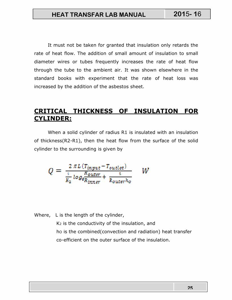
CRITICAL THICKNESS OF INSULATION FOR
CYLINDER:
When a solid cylinder of radius R1 is insulated with an insulation
of thickness(R2-R1), then the heat flow from the surface of the solid
cylinder to the surrounding is given by
Where, L is the length of the cylinder,
K2 is the conductivity of the insulation, and
hO is the combined(convection and radiation) heat transfer
co-efficient on the outer surface of the insulation.
HEAT TRANSFAR LAB MANUAL 2015- 16

26
DESCRIPTION:
The experimental set-up consists of a copper pipe of 38mm
diameter divided into four zones of 150mm each. The zone 1 is a bare
pipe, and zone 2 is wound with asbestos rope to 60mm dia, and that
of zone 3 to 90mm dia and zone 4 to 110mm dia. The heater of 500
watts is centred along the length of the pipe (150x4=600mm).
Heater regulator to supply the regulated power input to the
heater. Digital Voltmeter and Ammeter to measure poser input ot
the heater. Thermocouples at suitable position to measure the
temperatures of body and the air. Digital Temperature Indicator
with channel selector to measure the temperatures.
Control panel to house all the instrumentation.
With this the whole arrangement is mounted on an aesthetically designed self-sustained MS powder coated frame with a separate
NOVAPAN Board control panel.
EXPERIMENTATION:
AIM: To determine combined convective and radiation heat transfer
coefficient at each zone and compare them to decide the critical
thickness of insulation.
PROCEDURE:
1. Switch on the MCB and then console on switch to activate the
control panel.
HEAT TRANSFAR LAB MANUAL 2015- 16
27
2. Switch on the heater and set the voltage (say 40V) using the
heater regulator and digital voltmeter.
3. Wait for reasonable time to allow temperatures to reach steady
state.
4. Measure the voltage, current and temperatures from T1 to T7 at
known time interval.
5. Calculate the e heat transfer co-efficient using the procedure
given.
6. Repeat the experiment for different values of power input to the
heater.
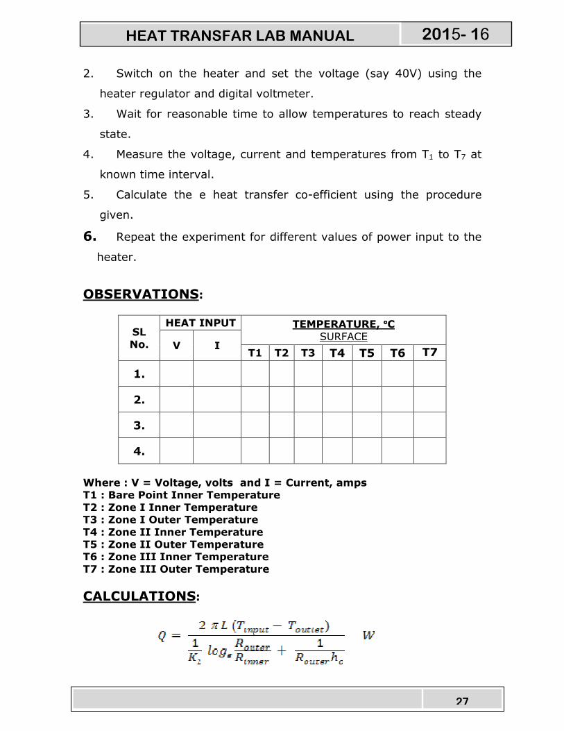
OBSERVATIONS:
SL
No.
HEAT INPUT TEMPERATURE, °°°°C
SURFACE V I
T1 T2 T3 T4 T5 T6 T7
1.
2.
3.
4.
Where : V = Voltage, volts and I = Current, amps T1 : Bare Point Inner Temperature
T2 : Zone I Inner Temperature T3 : Zone I Outer Temperature
T4 : Zone II Inner Temperature T5 : Zone II Outer Temperature T6 : Zone III Inner Temperature
T7 : Zone III Outer Temperature
CALCULATIONS:
HEAT TRANSFAR LAB MANUAL 2015- 16
28
where, Q = heat given to the heater = V x I watts.
Router/inner indicates respective radius of the zones.
Tinput/outlet indicates respective temp. of the zones.
L = 0.150m
K2 = Thermal conductivity of insulation.
RESULT:
Draw the graph of ‘h’ versus ‘Tm’ for theoretical and practical calculations and compare the results.
Reference:
7. Heat and Mass transfer by Arora & Domkundwar 8. Chemical Engineers’ Handbook, by Robert H. Perry / Cecil H. Chilton Publication: McGraw – Hill Book Company (6th edition)
PRECAUTIONS:
14. Check all the electrical connections.
15. Do not run the equipment if the voltage is below 180V.
16. Make sure that heater regulator is at the minimum position
before switching on the console.
17. Do not attempt to alter the equipment as this may cause
damage to the whole system.
HEAT TRANSFAR LAB MANUAL 2015- 16
29
HEAT TRANSFER THROUGH
NATURAL CONVECTION
INTRODUCTION:
There are certain situations in which the fluid motion is
produced due to change in density resulting from temperature
gradients. The mechanism of heat transfer in these situations is called
free or natural convection. Free convection is the principal mode of
heat transfer from pipes, transmission lines, refrigerating coils, hot
radiators etc.
The movement of fluid in free convection is due to the fact that
the fluid particles in the immediate vicinity of the hot object become
warmer than the surrounding fluid resulting in a local change of
density. The colder fluid creating convection currents would replace
the warmer fluid. These currents originate when a body force
(gravitational, centrifugal, electrostatic etc) acts on a fluid in which
there are density gradients. The force, which induces these convection
currents, is called a buoyancy force that is due to the presence of a
density gradient with in the fluid and a body force. Grashoffs number
a dimensionless quantity plays a very important role in natural
convection.
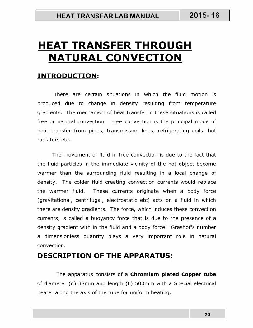
DESCRIPTION OF THE APPARATUS:
The apparatus consists of a Chromium plated Copper tube
of diameter (d) 38mm and length (L) 500mm with a Special electrical
heater along the axis of the tube for uniform heating.
HEAT TRANSFAR LAB MANUAL 2015- 16

30
Four thermocouples are fixed on the tube surface with a phase
angle of 90°.
An arrangement to change the position of the tube to vertical or
horizontal position is provided.
Front transparent acrylic enclosure to minimize the
disturbances of the surrounding and also for safety of the tube when
not in use.
Contol panel instrumentation consists of:
d. Digital Temperature Indicator with channel selector.
e. Digital Voltmeter & Ammeter for power
measurement.
f. Heater regulator to regulate the input power.
With this, the setup is mounted on an aesthetically designed MS
Powder coated frame with MOVAPAN Board control panel to monitor all
the processes considering all safety and aesthetics factors.
HEAT TRANSFAR LAB MANUAL 2015- 16

31
EXPERIMENTATION:
AIM:
To determine the natural heat transfer coefficient ‘h’ from the
surface of the tube in both vertical and horizontal position.
PROCEDURE:
9. Keep the tube in the vertical position.
10. Switch on MCB and then CONSOLE ON switch.
11. Switch on the heater and set the voltage (say 40V) using
heater regulator and the digital voltmeter.
12. Wait for sufficient time to allow temperature to reach
steady values.
13. Note down the Temperatures 1 to 4 using the channel
selector and digital temperature indicator.
14. Note down the ammeter and voltmeter readings.
15. Calculate the convection heat transfer co-efficient using
the procedure given below.
16. Repeat the experiment for different heat inputs and also
for horizontal position with different heat inputs.
NOTE:
1. The experiment should be carried out in the absence of wind
flow through the window as well as in the absence of fan for
better results.
2. For better result, the horizontal and vertical experiments should
be conducted after the tube is cooled down to almost room
temperature.
3. For comparison of results in horizontal and vertical position the
temperatures should be considered for equal interval of time, in
both cases.
HEAT TRANSFAR LAB MANUAL 2015- 16
32
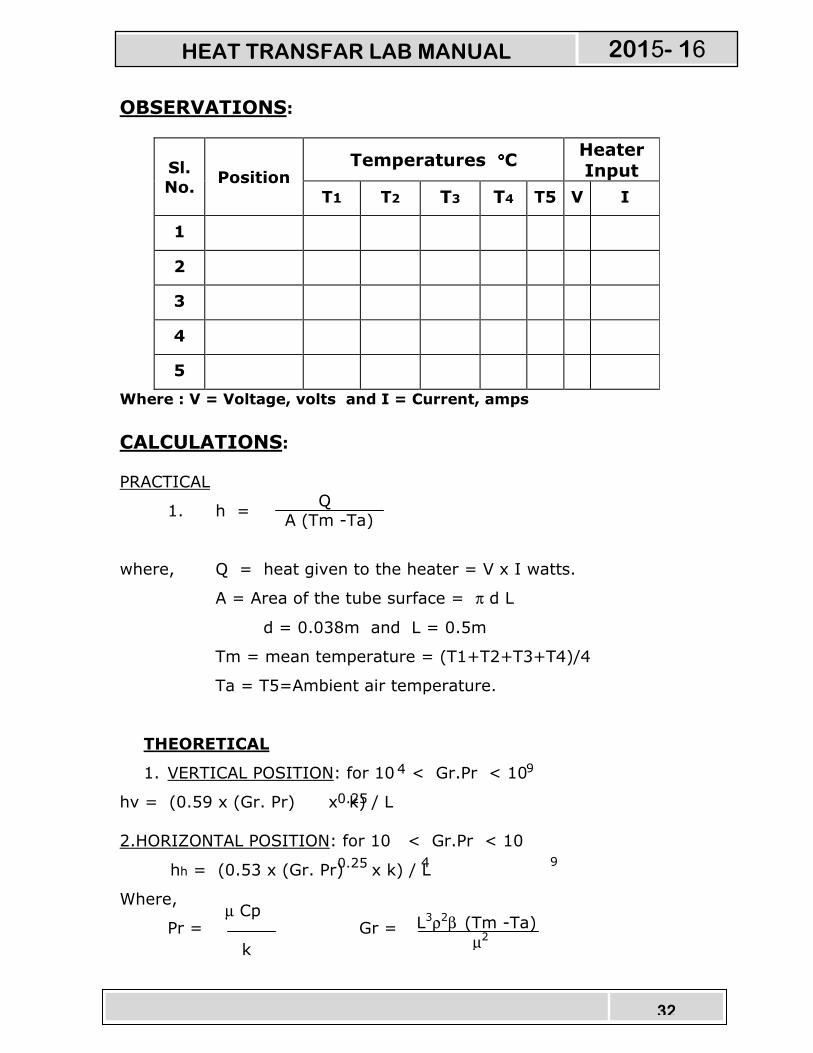
OBSERVATIONS:
Sl.
No. Position
Temperatures °°°°C Heater Input
T1 T2 T3 T4 T5 V I
1
2
3
4
5
Where : V = Voltage, volts and I = Current, amps
CALCULATIONS:
PRACTICAL
1. h =
where, Q = heat given to the heater = V x I watts.
A = Area of the tube surface = π d L
d = 0.038m and L = 0.5m
Tm = mean temperature = (T1+T2+T3+T4)/4
Ta = T5=Ambient air temperature.
THEORETICAL
1. VERTICAL POSITION: for 10 < Gr.Pr < 10
hv = (0.59 x (Gr. Pr) x k) / L
2.HORIZONTAL POSITION: for 10 < Gr.Pr < 10
hh = (0.53 x (Gr. Pr) x k) / L
Where,
Pr = Gr =
Q
A (Tm -Ta)
4 9
4 9
µ Cp
k
L3ρ2β (Tm -Ta)
µ2
0.25
0.25
HEAT TRANSFAR LAB MANUAL 2015- 16
33
β = 1/(273+Tm)
All the properties of air should be taken at (Tm + Ta)/2 from the data
hand book.
Here , L is the characteristic length and is given as:
L = L = 0.5m for vertical position.
L = d = 0.038 for horizontal position.
RESULT:
Draw the graph of ‘h’ versus ‘Tm’ for vertical and horizontal positions of the tube actually and theoretically calculated and compare
the results.
Reference:
9. Heat and Mass transfer by Arora & Domkundwar
10. Chemical Engineers’ Handbook, by Robert H. Perry / Cecil H. Chilton
Publication: McGraw – Hill Book Company (6th edition)
PRECAUTIONS:
18. Check all the electrical connections.
19. Do not run the equipment if the voltage is below 180V.
20. Make sure that heater regulator is at the minimum position
before switching on the console.
21. Do not attempt to alter the equipment as this may cause
damage to the whole system.
HEAT TRANSFAR LAB MANUAL 2015- 16
34
PARALLEL & COUNTER FLOW HEAT EXCHANGER
INTRODUCTION:
Heat exchangers are devices in which heat is transferred from
one fluid to another. The fluids may be in direct contact with each
other or separated by a solid wall. Heat Exchangers can be classified
based on its principle of operation and the direction of flow. The
temperature of the fluids change in the direction of flow and
consequently there occurs a change in the thermal head causing the
flow of heat.
The temperatures profiles at the two fluids in parallel and
counter flow are curved and has logarithmic variations. LMTD is less
then the arithmetic mean temperature difference. So, it is always safer
for the designer to use LMTD so as to provide larger heating surface
for a certain amount of heat transfer.
DESCRIPTION OF THE APPARATUS:
The apparatus consists of concentric tubes. The inner tube is
made of copper while the outer tube is made of Stainless Steel.
Insulation is provided with mica sheet and asbestos rope for
effective heat transfer.
HEAT TRANSFAR LAB MANUAL 2015- 16

35
Provision has been made for hot water generation by means
of geyser.
Change - Over Mechanism is provided to change the direction
of flow of cold water in a single operation.
ACRYLIC Rotameters of specific range is used for direct
measurement of water flow rate.
Thermocouples are placed at appropriate positions which carry
the signals to the temperature indicator. A Digital Temperature
indicator with channel selector is provided to measure the
temperature.
The whole arrangement is mounted on an Aesthetically
designed self sustained sturdy frame made of MS tubes with
NOVAPAN board control panel. The control panel houses all the
indicators, accessories and necessary instrumentations.
EXPERIMENTATION:
AIM:
To determine LMTD & Effectiveness of the heat exchanger
under parallel and counter Flow arrangement.
PROCEDURE:
17. Switch ON mains and the CONSOLE.
18. Start the flow on the hot water side.
19. Start the flow through annulus also.
20. Set the exchanger for parallel or counter flow using the
change over mechanism.
21. Switch ON the heater of the geyser.
HEAT TRANSFAR LAB MANUAL 2015- 16
36
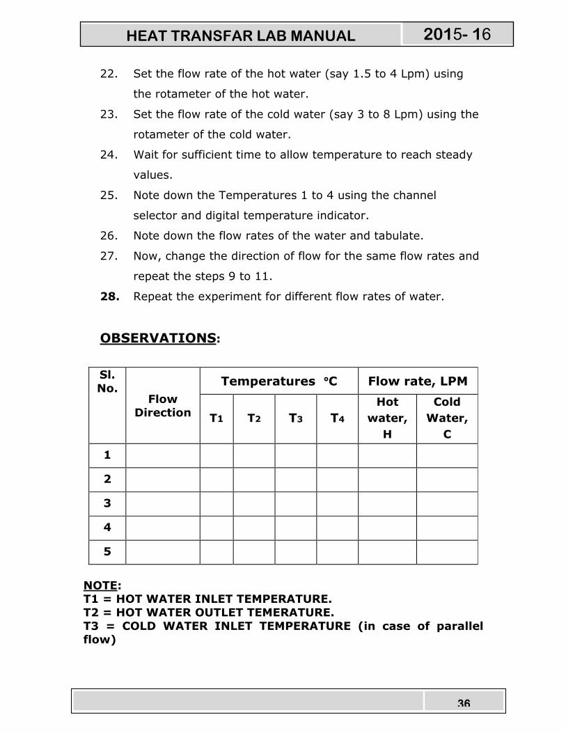
22. Set the flow rate of the hot water (say 1.5 to 4 Lpm) using
the rotameter of the hot water.
23. Set the flow rate of the cold water (say 3 to 8 Lpm) using the
rotameter of the cold water.
24. Wait for sufficient time to allow temperature to reach steady
values.
25. Note down the Temperatures 1 to 4 using the channel
selector and digital temperature indicator.
26. Note down the flow rates of the water and tabulate.
27. Now, change the direction of flow for the same flow rates and
repeat the steps 9 to 11.
28. Repeat the experiment for different flow rates of water.
OBSERVATIONS:
Sl.
No. Flow
Direction
Temperatures °°°°C Flow rate, LPM
T1 T2 T3 T4
Hot
water,
H
Cold
Water,
C
1
2
3
4
5
NOTE: T1 = HOT WATER INLET TEMPERATURE.
T2 = HOT WATER OUTLET TEMERATURE.
T3 = COLD WATER INLET TEMPERATURE (in case of parallel flow)
HEAT TRANSFAR LAB MANUAL 2015- 16

37
COLD WATER OUTLET TEMPERATURE (in case of counter
flow) T4 = COLD WATER OUTLET TEMPERATURE (in case of parallel
flow) COLD WATER INLET TEMPERATURE (in case of counter
flow)
CALCULATIONS:
6. HEAT TRANSFER RATE ,Q
Q = Watts
WHERE,
QH = heat transfer rate from hot water and is given by:
= mH x CPH x (T1 – T2) W
Where,
mh = mass flow rate of hot water = H/60 kg/sec.
CPH = Specific heat of hot water from table at temp. (T1+T2)/2
QC = heat transfer rate from cold water and is given by:
= mC x CPC x (T3 ~ T4) W
Where,
mC = mass flow rate of cold water = C/60 kg/sec.
CPC = Specific heat of hot water from table at temp. (T3+T4)/2
7. LMTD – Logarithmic mean temperature difference:
∆TM =
Where,
∆TI = (THI - TCI ) for parallel flow
∆TI = (THI - TCO ) for counter flow
QH x QC
2
∆TI - ∆TO
ln(∆TI/∆TO)
HEAT TRANSFAR LAB MANUAL 2015- 16

38
∆TO = (THO - TCO ) for parallel flow
∆TO = (THO - TCI ) for counter flow
NOTE: The suffix H = HOT WATER
C = COLD WATER
I = INLET
O = OUTLET
8. OVERALL HEAT TRANSFER CO-EFFICIENT:
U = W/m °K
Where,
Q = heat transfer rate
A = π x DO x L m² where, DO = 0.02m & L = 1m.
∆TM = LMTD.
9. EFFECTIVENESS OF HEAT EXCHANGER, E
EXPERIMENTAL:
EEXP = IF CMAX > CMIN
EEXP = IF CMAX < CMIN
THEORETICAL:
ETH = For PARALLEL FLOW
ETH = For COUNTER FLOW
Q A x ∆TM
(TCO - TCI )
(THI - TCI )
(THI - THO )
(THI - TCI )
1 – e
(1 + R)
-NTU (1 + R)
1 – e
1 - Re
-NTU (1 – R)
-NTU (1 – R)
HEAT TRANSFAR LAB MANUAL 2015- 16

39
Where,
CMAX = mH x CPH
CMIN = mC x CPC
R = CMIN/ CMAX
NTU = No. of Transfer units is given by
=
CM = minimum of CMIN & CMAX
Other notations have their usual meaning.
10. PERCENTAGE OF ERROR, %ERROR
%ERROR = x 100
Reference:
11. Heat and Mass transfer by Arora & Domkundwar
12. Chemical Engineers’ Handbook, by Robert H. Perry / Cecil H. Chilton
Publication: McGraw – Hill Book Company (6th edition)
PRECAUTIONS:
22. Check all the electrical connections.
23. Do not run the equipment if the voltage is below 180V.
24. Do not attempt to alter the equipment as this may cause
damage to the whole system.
U x A CM
ETH - EEXP
ETH
HEAT TRANSFAR LAB MANUAL 2015- 16

40
HEAT TRANSFER THROUGH
PIN – FIN
INTRODUCTION:
A spine or pin-fin is an extended surface of
cylindrical or conical shape used for increasing the heat transfer rates
from the surfaces, whenever it is not possible to increase the rate fo
heat transfer either by increasing heat transfer co-efficient or by
increasing the temperature difference between the surface and
surrounding fluids.
The fins are commonly used on engine heads of
scooter, motorcycles, as well as small capacity compressors. The pin
type fins are also used on the condenser of a domestic refrigerator.
DESCRIPTION OF THE APPARATUS:
The apparatus consists of
Pin type fin of dia 12mm and 150 mm long made of copper
with suitable temperature points.
Heater of 250watts capacity.
Heater regulator to supply the regulated power input to the heater.
Digital Voltmeter and Ammeter to measure power input to
the heater.
HEAT TRANSFAR LAB MANUAL 2015- 16

41
Thermocouples at suitable position to measure the surface
temperatures of the fin.
Digital Temperature Indicator with channel selector to
measure the temperatures.
Blower unit to blow air through the duct with orifice meter and
acrylic manometer to measure the air flow rate from the blower. A
control valve is provided to regulate the air flow.
Control panel to house all the instrumentation.
With this the whole arrangement is mounted on an aesthetically
designed self-sustained MS powder coated frame with a separate
control panel.
EXPERIMENTATION:
AIM:
� To find out the temperature distribution along the given fin
for constant base temperature under natural and force flow
conditions.
� To find out effectiveness of the fin under both conditions.
PROCEDURE:
7. Switch on the MCB and then console on switch to activate the
control panel.
HEAT TRANSFAR LAB MANUAL 2015- 16
42
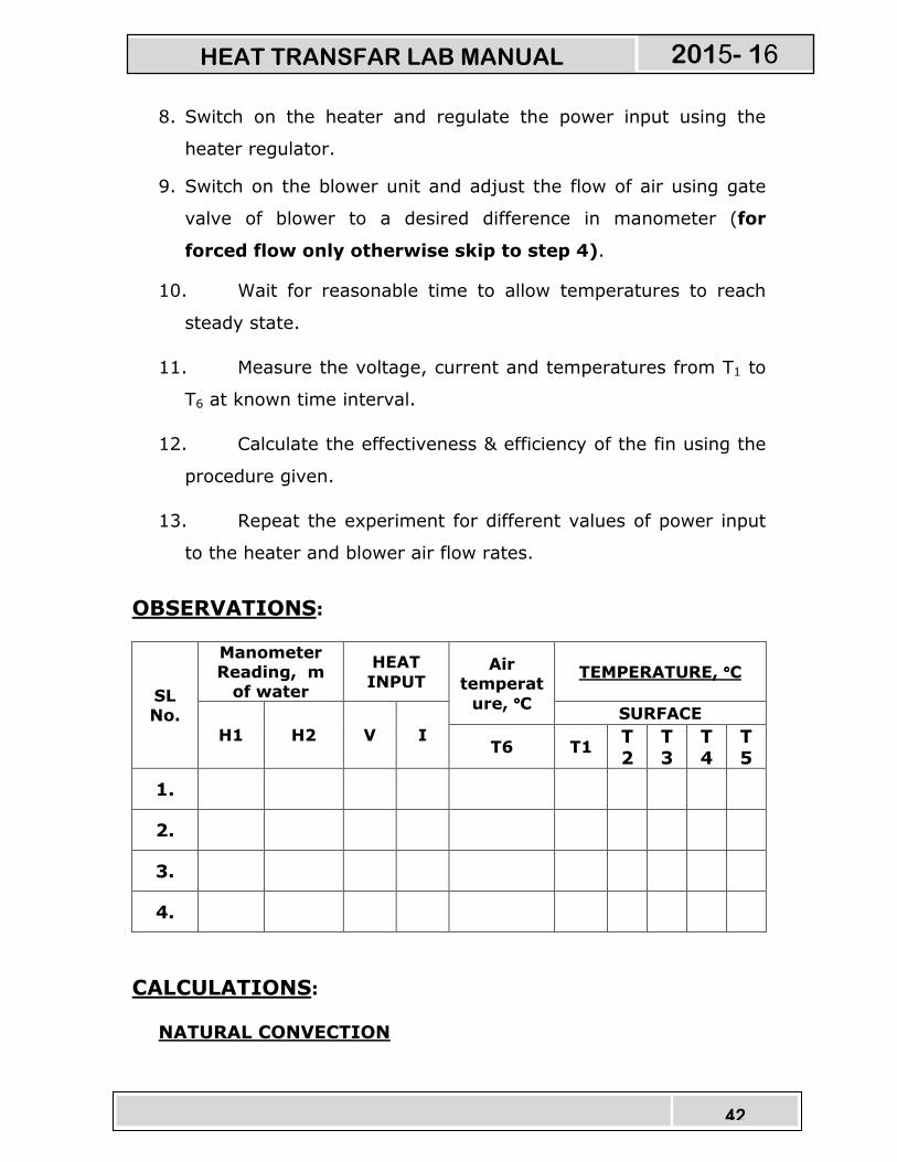
8. Switch on the heater and regulate the power input using the
heater regulator.
9. Switch on the blower unit and adjust the flow of air using gate
valve of blower to a desired difference in manometer (for
forced flow only otherwise skip to step 4).
10. Wait for reasonable time to allow temperatures to reach
steady state.
11. Measure the voltage, current and temperatures from T1 to
T6 at known time interval.
12. Calculate the effectiveness & efficiency of the fin using the
procedure given.
13. Repeat the experiment for different values of power input
to the heater and blower air flow rates.
OBSERVATIONS:
SL No.
Manometer Reading, m of water
HEAT
INPUT Air
temperat
ure, °°°°C
TEMPERATURE, °°°°C
H1 H2 V I
SURFACE
T6 T1 T
2
T
3
T
4
T
5
1.
2.
3.
4.
CALCULATIONS:
NATURAL CONVECTION
HEAT TRANSFAR LAB MANUAL 2015- 16
43
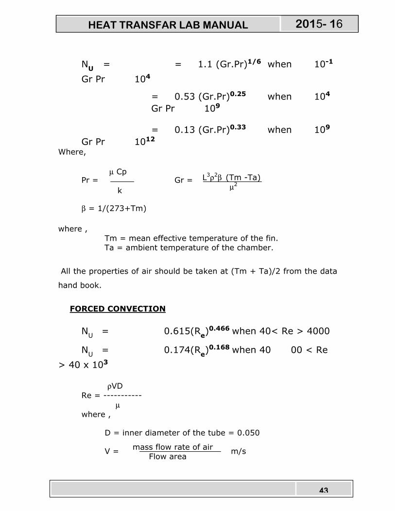
NU = = 1.1 (Gr.Pr)1/6 when 10-1
Gr Pr 104
= 0.53 (Gr.Pr)0.25 when 104
Gr Pr 109
= 0.13 (Gr.Pr)0.33 when 109
Gr Pr 1012 Where,
Pr = Gr =
β = 1/(273+Tm) where ,
Tm = mean effective temperature of the fin. Ta = ambient temperature of the chamber.
All the properties of air should be taken at (Tm + Ta)/2 from the data
hand book.
FORCED CONVECTION
NU = 0.615(R
e)0.466 when 40< Re > 4000
NU = 0.174(R
e)0.168 when 40 00 < Re
> 40 x 103 ρVD
Re = -----------
µ
where ,
D = inner diameter of the tube = 0.050
V = m/s mass flow rate of air
Flow area
µ Cp
k
L3ρ2β (Tm -Ta)
µ2
HEAT TRANSFAR LAB MANUAL 2015- 16
44
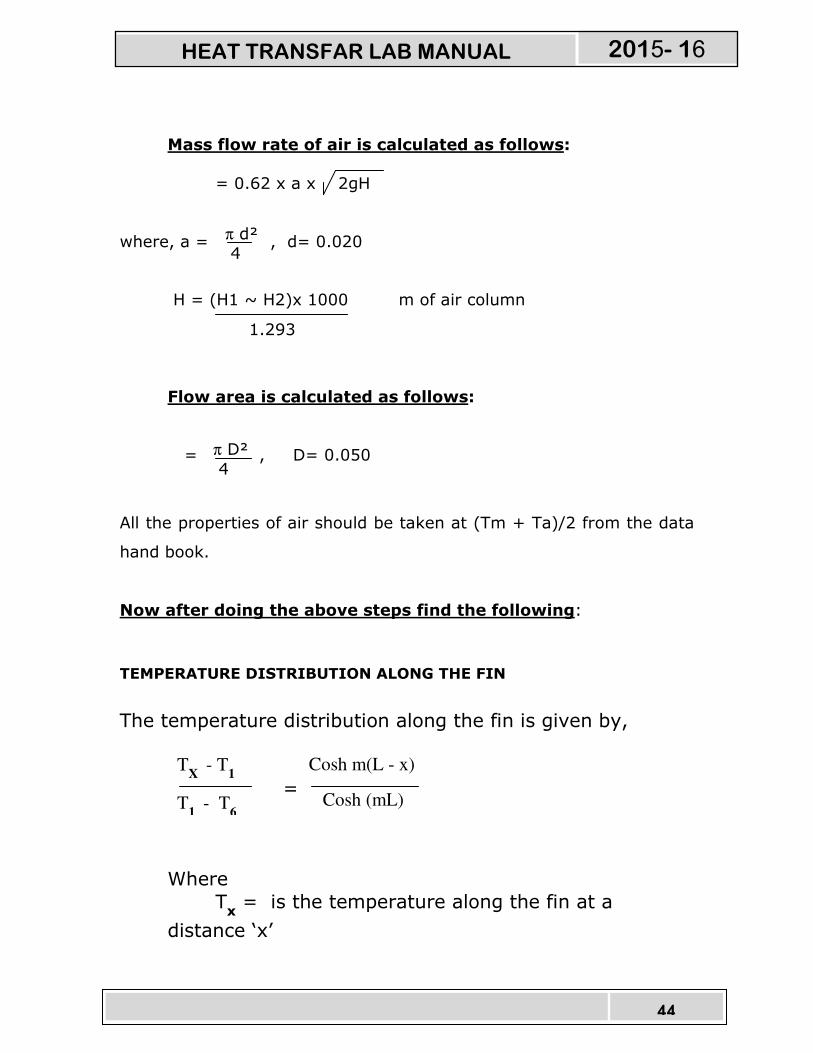
Mass flow rate of air is calculated as follows:
= 0.62 x a x 2gH
where, a = , d= 0.020
H = (H1 ~ H2)x 1000 m of air column
Flow area is calculated as follows:
= , D= 0.050
All the properties of air should be taken at (Tm + Ta)/2 from the data
hand book.
Now after doing the above steps find the following:
TEMPERATURE DISTRIBUTION ALONG THE FIN
The temperature distribution along the fin is given by,
=
Where
Tx = is the temperature along the fin at a
distance ‘x’
π d²
4
1.293
π D²
4
TX
- T1
T1
- T6
Cosh m(L - x)
Cosh (mL)
HEAT TRANSFAR LAB MANUAL 2015- 16
45
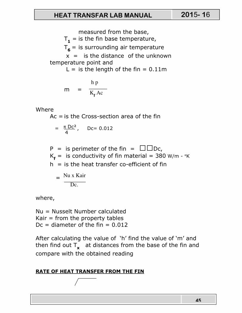
measured from the base,
T1 = is the fin base temperature,
T6 = is surrounding air temperature
x = is the distance of the unknown
temperature point and
L = is the length of the fin = 0.11m
m =
Where
Ac = is the Cross-section area of the fin
= , Dc= 0.012
P = is perimeter of the fin = Dc, K
f = is conductivity of fin material = 380 W/m - °K
h = is the heat transfer co-efficient of fin
=
where,
Nu = Nusselt Number calculated
Kair = from the property tables Dc = diameter of the fin = 0.012
After calculating the value of ‘h’ find the value of ‘m’ and
then find out Tx at distances from the base of the fin and
compare with the obtained reading
RATE OF HEAT TRANSFER FROM THE FIN
h p
Kf Ac
π Dc²
4
Nu x Kair
Dc.
HEAT TRANSFAR LAB MANUAL 2015- 16

46
Q = hPKFA x (Tm – Ta) x tanh mL
Where the units have their usual meaning
EFFICIENCY OF THE FIN
Ηmech =
Reference:
13. Heat and Mass transfer by Arora & Domkundwar
14. Chemical Engineers’ Handbook, by Robert H. Perry / Cecil H. Chilton
Publication: McGraw – Hill Book Company (6th edition)
PRECAUTIONS:
25. Check all the electrical connections.
26. Do not run the equipment if the voltage is below 180V.
27. Do not obstruct flow of air while experiment is going on.
28. Do not turn the heater regulator to the maximum as soon
as the equipment is started.
tan h mL
mL
25 25 25 25 10 40
HEAT TRANSFAR LAB MANUAL 2015- 16
47
29. Do not attempt to alter the equipment as this may cause
damage to the whole system.
HEAT TRANSFAR LAB MANUAL 2015- 16
48
STEFAN BOLTZMAN’S
APPARATUS
INTRODUCTION:
The most commonly used relationship in radiation
heat transfer is the Stefan Boltzman’s law which relates the heat
transfer rate to the temperatures of hat and cold surfaces.
q = σ A ( TH – TC )
Where,
q = rate of heat transfer, watts
σ = Stefan Boltzman’s constant = 5.669 x 10 watts/m² °K
A = Surface area, m²
TH = Temperature of the hot body, °K
TC = Temperature of the cold body, °K
The above equation is applicable only to black bodies 9for
example a piece of metal covered with carbon black approximates this
behavior) and is valid only for thermal radiation. Other types of bodies
(like a glossy painted surface or a polished metal plate) do not radiate
as much energy as the black body but still the total radiation emitted
generally follow temperature proportionality.
DESCRIPTION OF THE APPARATUS:
4 4
4 -8
HEAT TRANSFAR LAB MANUAL 2015- 16
49
The apparatus consists of
Copper hemispherical enclosure with insulation.
SS jacket to hold the hot water.
Over head water heater with quick release mechanism and the
thermostat to generate and dump the hot water. Heater regulator to supply the regulated power input to the heater.
Thermocouples at suitable position to measure the surface
temperatures of the absorber body.
Digital Temperature Indicator with channel selector to
measure the temperatures.
Control panel to house all the instrumentation.
With this the whole arrangement is mounted on an aesthetically designed self-sustained MS powder coated frame with a separate
control panel.
EXPERIMENTATION:
AIM:
� To determine the Stefan Boltman’s constant. PROCEDURE:
14. Fill water slowly into the overhead water heater.
15. Switch on the supply mains and console.
16. Switch on the heater and regulate the power input using
the heater regulator. (say 60 – 85 °C)
17. After water attains the maximum temperature, open the valve of
the heater and dump to the enclosure jacket.
HEAT TRANSFAR LAB MANUAL 2015- 16

50
18. Wait for about few seconds to allow hemispherical enclosure to
attain uniform temperature – the chamber will soon reach the
equilibrium. Note the enclosure temperature.
19. Insert the Test specimen with the sleeve into its position and
record the temperature at different instants of time using the
stop watch.
20. Plot the variation of specimen temperature with time and get the
slope of temperature versus time variation at the time t = 0 sec
21. Calculate the Stefan Boltzman’s constant using the equations
provided.
22. Repeat the experiment 3 to 4 times and calculate the average
value to obtain the better results.
OBSERVATIONS:
Enclosure Temperature, Te = Initial Temperature of the specimen, Ts =
Time, t Specimen
Temperature,
Ts
5
10
15
20
25
30
CALCULATIONS:
HEAT TRANSFAR LAB MANUAL 2015- 16
51
STEFAN BOLTMAN’S CONSTANT IS CALCULATED USING THE RELATION:
σ =
Where,
m = mass of the test specimen = 0.0047Kg
Cp = Specific heat of the specimen = 410 J/Kg °C
Te = Enclosure temperature, °K
TS = Initial temperature of the specimen, °K
(dTa/dt) = calculated from graph.
AD = Surface area of the test specimen
= πd²/4
where d = 0.015m
RESULT:
Stefan Boltzman’s constant is _______________
Reference:
15. Heat and Mass transfer by Arora & Domkundwar
16. Chemical Engineers’ Handbook, by Robert H. Perry / Cecil H. Chilton
Publication: McGraw – Hill Book Company (6th edition)
PRECAUTIONS: 30. Check all the electrical connections.
31. Do not run the equipment if the voltage is below 180V.
m Cp (dTs/dt)t=0
4 4 AD ( Te – TS )
HEAT TRANSFAR LAB MANUAL 2015- 16
52
32. Do not switch on the heater without water in the overhead
tank.
33. Do not turn the heater regulator to the maximum as soon
as the equipment is started.
34. Do not attempt to alter the equipment as this may cause
damage to the whole system.
HEAT TRANSFAR LAB MANUAL 2015- 16
53
THERMAL CONDUCTIVITY OF
CONCENTRIC SPHERE
INTRODUCTION:
Thermal conductivity is the physical property of material
denoting the ease with a particular substance can accomplish the
transmission of thermal energy by molecular motion.
Thermal conductivity of a material is found, to depend on the
chemical composition of the substances of which it is a composed, the
phase (i.e. gas, liquid or solid) in which its crystalline structure if a
solid, the temperature & pressure to which it is subjected and whether
or not it is homogeneous material.
Thermal energy in solids may be conducted in two modes. They
are:
� LATTICE VIBRATION:
� TRANSPORT BY FREE ELECTRONS.
In good electrical conductors a rather large number of free
electrons move about in a lattice structure of the material. Just as
these electrons may transport may transport electric charge, they may
also carry thermal energy from a high temperature region to low
temperature region. In fact, these electrons are frequently referred as
the electron gas. Energy may also be transmitted as vibrational energy
in the lattice structure of the material. In general, however, this latter
mode of energy transfer is not as large as the electron transport and it
HEAT TRANSFAR LAB MANUAL 2015- 16

54
is for this reason that good electrical conductors are almost always
good heat conductors, for eg: ALUMINIUM, COPPER & SILVER.
With the increase in temperature, however the increased lattice
vibrations come in the way of electron transport by free electrons and
for most of the pure metals the thermal conductivity decreases with
the increase in the temperature.
DESCRIPTION OF THE APPARATUS:
The apparatus consists of the COPPER sphere of 100mm dia
and 175mm dia concentrically placed. Heat is provided by means
of oil bath heater arrangement. Thermocouples are provided at the
suitable points to measure the surface and inner temperatures. Proper
insulation is provided to minimize the heat loss. The temperature
is shown by means of the digital temperature indicator on the
control panel, which also consists of heater regulator and other
accessories instrumentation having good aesthetic looks and safe
design.
HEAT TRANSFAR LAB MANUAL 2015- 16
55
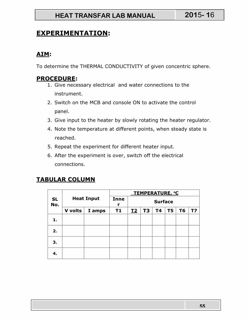
EXPERIMENTATION: AIM:
To determine the THERMAL CONDUCTIVITY of given concentric sphere.
PROCEDURE: 1. Give necessary electrical and water connections to the
instrument.
2. Switch on the MCB and console ON to activate the control
panel.
3. Give input to the heater by slowly rotating the heater regulator.
4. Note the temperature at different points, when steady state is
reached.
5. Repeat the experiment for different heater input.
6. After the experiment is over, switch off the electrical
connections.
TABULAR COLUMN
SL
No.
Heat Input
TEMPERATURE, °°°°C
Inne
r Surface
V volts I amps T1 T2 T3 T4 T5 T6 T7
1.
2.
3.
4.
HEAT TRANSFAR LAB MANUAL 2015- 16

56
CALCULATIONS: 1. HEAT INPUT TO THE SYSTEM, QI
Heat input to the system = Heat carried away by water
Q = V x I Watts
Where,
V = Voltage
I = Current
2. THERMAL CONDUCTIVITY OF THE Concentric Sphere, K
Where,
r1 = radius of the inner sphere = 0.05m
r2 = radius of the outer sphere = 0.0875m
K = Thermal conductivity of COPPER sphere
T1 = Temp. of the inner sphere
Tavg =Temp of the outer sphere
= ( T2+T3+T4+T5+T6+T7)/4
HEAT TRANSFAR LAB MANUAL 2015- 16

57
PRECAUTIONS: 35. Input should be given very slowly.
36. Do not run the equipment if the voltage is below 180V.
37. Check all the electrical connections before running.
38. Before starting and after finishing the experiment the
heater controller should be in off position.
39. Do not attempt to alter the equipment as this may cause
damage to the whole system.
Reference:
17. PROCESS HEAT TRANSFER, by Wareh L. McCabe
Julian C. Smith Peter Harioth
Publication: McGraw Hill (6th edition)
18. Heat and Mass transfer by Arora & Domkundwar
19. Chemical Engineers’ Handbook, by
Robert H. Perry / Cecil H. Chilton Publication: McGraw – Hill Book Company (6th edition)
HEAT TRANSFAR LAB MANUAL 2015- 16

58
THERMAL CONDUCTIVITY OF METAL
ROD
INTRODUCTION:
Thermal conductivity is the physical property of material
denoting the ease with a particular substance can accomplish the
transmission of thermal energy by molecular motion.
Thermal conductivity of a material is found, to depend on the
chemical composition of the substances of which it is a composed, the
phase (i.e. gas, liquid or solid) in which its crystalline structure if a
solid, the temperature & pressure to which it is subjected and whether
or not it is homogeneous material.
Thermal energy in solids may be conducted in two modes. They
are:
� LATTICE VIBRATION:
� TRANSPORT BY FREE ELECTRONS.
In good electrical conductors a rather large number of free
electrons move about in a lattice structure of the material. Just as
these electrons may transport may transport electric charge, they may
also carry thermal energy from a high temperature region to low
temperature region. In fact, these electrons are frequently referred as
the electron gas. Energy may also be transmitted as vibrational energy
in the lattice structure of the material. In general, however, this latter
mode of energy transfer is not as large as the electron transport and it
HEAT TRANSFAR LAB MANUAL 2015- 16
59
is for this reason that good electrical conductors are almost always
good heat conductors, for eg: ALUMINIUM, COPPER & SILVER.
With the increase in temperature, however the increased lattice
vibrations come in the way of electron transport by free electrons and
for most of the pure metals the thermal conductivity decreases with
the increase in the temperature.
DESCRIPTION OF THE APPARATUS:
The apparatus consists of the ALUMINIUM rod of 200mm test
section. Heat is provided by means of band heater at one end and
released through water jacket arrangement. Thermocouples are
provided at the suitable points to measure the surface and water
temperatures. Proper insulation is provided to minimize the heat
loss. The temperature is shown by means of the digital temperature
indicator on the control panel, which also consists of heater
regulator and other accessories instrumentation having good
aesthetic looks and safe design.
HEAT TRANSFAR LAB MANUAL 2015- 16
60
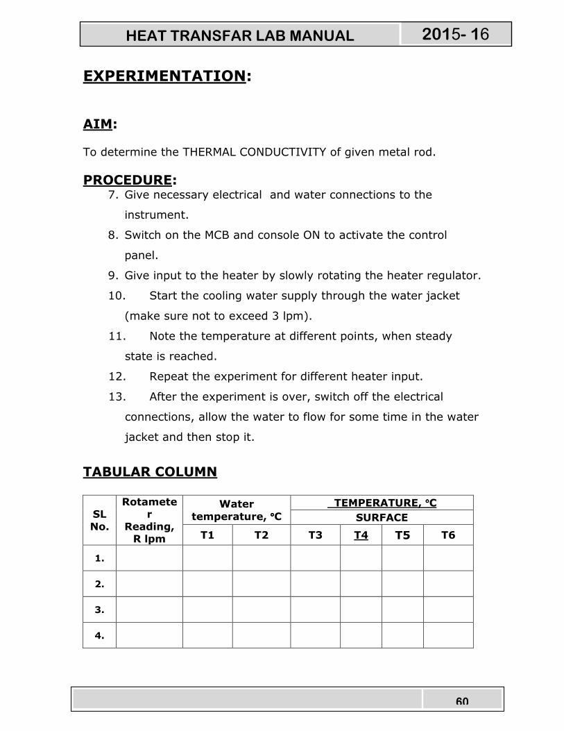
EXPERIMENTATION: AIM:
To determine the THERMAL CONDUCTIVITY of given metal rod.
PROCEDURE: 7. Give necessary electrical and water connections to the
instrument.
8. Switch on the MCB and console ON to activate the control
panel.
9. Give input to the heater by slowly rotating the heater regulator.
10. Start the cooling water supply through the water jacket
(make sure not to exceed 3 lpm).
11. Note the temperature at different points, when steady
state is reached.
12. Repeat the experiment for different heater input.
13. After the experiment is over, switch off the electrical
connections, allow the water to flow for some time in the water
jacket and then stop it.
TABULAR COLUMN
SL
No.
Rotameter
Reading, R lpm
Water
temperature, °°°°C
TEMPERATURE, °°°°C
SURFACE
T1 T2 T3 T4 T5 T6
1.
2.
3.
4.
HEAT TRANSFAR LAB MANUAL 2015- 16

61
π d²
4
R
60
CALCULATIONS: 3. CROSS – SECTIONAL AREA OF METAL ROD:
A = m²
Where,
d = diameter of the of the metal rod = 0.05 m.
π = constant
4. MASS FLOWRATE OF WATER, mW
mW = kg/ sec.
Where,
R = Rotameter reading in lpm.
5. HEAT INPUT TO THE SYSTEM, QI
Heat input to the system = Heat carried away by water
QI = QW
QW = mW x CpW x ∆TW Watts.
Where,
mW = mass flowrate of water, kg/sec.
CpW = Specific heat of water = 4180 J/kg °K .
∆TW = Temperature difference of water inlet and outlet from
the water jacket.
= (T1 ~ T2) °K
HEAT TRANSFAR LAB MANUAL 2015- 16

62
6. THERMAL CONDUCTIVITY OF THE METAL ROD, K
K = W/m - °K
Where,
A = cross – sectional area of the rod
(dT/dX)A = slope calculated from graph. (shown in the diagram)
Where ‘X’ = test length with thermocouple points as shown below
QI
A x (dT/dX)
T
X
dT
dX
50 50 50 25 25
HEATER COOLING
JACKET T3 T4 T5 T6
HEAT TRANSFAR LAB MANUAL 2015- 16
63
PRECAUTIONS: 40. Do not give heater input without the supply of water.
41. Input should be given very slowly.
42. Run the water in the jacket for about 5 min after the
experiment.
43. Do not run the equipment if the voltage is below 180V.
44. Check all the electrical connections before running.
45. Before starting and after finishing the experiment the
heater controller should be in off position.
46. Do not attempt to alter the equipment as this may cause
damage to the whole system.
Reference:
20. PROCESS HEAT TRANSFER, by Wareh L. McCabe
Julian C. Smith Peter Harioth
Publication: McGraw Hill (6th edition)
21. Heat and Mass transfer by Arora & Domkundwar
22. Chemical Engineers’ Handbook, by Robert H. Perry / Cecil H. Chilton
Publication: McGraw – Hill Book Company (6th edition)
HEAT TRANSFAR LAB MANUAL 2015- 16
64
TRANSIENT HEAT CONDUCTION
APPARATUS
INTRODUCTION:
When a body is subjected to heating or cooling, irrespective of
the material it requires certain time to attain steady state. Hence the
other way of expressing is that the unsteady process will occur till it
attains the steady process. In unsteady process the temperature will
change with respect to time. Although, temperature of the body is
generally expressed as the function of 3 different axis and time, it is
not easy to solve.
Unsteady state heating or cooling can be categorized as:
� PERIODIC HEAT FLOW : where the temperature within the
system undergoes periodic changes which may be regular or
irregular.
� NON – PERIODIC HEAT FLOW : where the temperature at
any point within the system changes non – linearly with
respect to time.
Unsteady state heat flow is very common in all heating or
cooling problems at the beginning of the system. Hardening by
qrenching, cooling of IC engine cylinders, and heating of boiler tubes
are common examples of unsteady state heat flow.
HEAT TRANSFAR LAB MANUAL 2015- 16

65
2. DESCRIPTION OF APPARATUS:
� The apparatus consists of a specially designed Stainless
Steel Tank with heater arrangement.
� An ALUMINIUM sphere is provided to study the experiment
with the stand to place in the heater tank.
� Heater regulator with Thermostat to supply the regulated power
input to the heater and to set the temperature.
� Thermocouples at suitable position to measure the temperatures.
� Digital Temperature Indicator with channel selector to measure
the temperatures.
� The whole arrangement is mounted on an Aesthetically
designed sturdy frame made of MS tubes and NOVAPAN Board
with all the provisions for holding the tanks and accessories.
3. EXPERIMENTATION:
vii. AIM:
� To determine heat transfer coefficient and instantaneous
heat transfer rate for transient heat conduction and draw the
graph of temperature variation with time
viii. PROCEDURE:
1. Take the fluid (water or oil) in the tank.
HEAT TRANSFAR LAB MANUAL 2015- 16
66
2. Heat the fluid to the required temperature say 70oC in case of
water and more than 100 oC in case of oil.
3. Note down the initial temperature of sphere and hot fluid.
4. Immerse the sphere in hot fluid bath for heating.
5. Note down the core and outer surface temperature of the sphere
at every 10 seconds till it attains fluid temperature.
6. Take out the sphere from hot fluid and cool it in atmospheric air.
7. Note down the temperature at every 10 second till it reaches
atmospheric condition.
8. Repeat the experiment for different temperatures of fluid.
ix. OBSERVATIONS Intial Temp. of the fluid, T∞ = ____ oC * T2 in case of water or oil T1 in case of air.
Intial Temp. of the sphere, To = T3 =____ oC
Sl. Temperatures °°°°C Time,
HEAT TRANSFAR LAB MANUAL 2015- 16

67
No. Tc = T4 To = T3 t sec
Note: Take T4 with respect to time for Heating process and
Take T3 with respect to time for Cooling process.
x. CALCULATIONS:
6. Determination of Heat Transfer Co-efficient, h
HEAT TRANSFAR LAB MANUAL 2015- 16

68
Where, Nu = Nusselt Number and is given by
for 1<GrPr<105
for 3x10⁵<GrPr<8x10⁵
Pr = Prandtal Number from handbook
Gr = Grashoff’ s Number & is given by
D = Diameter of sphere = 0.075 m
K = Thermal conductivity of fluid, W/mK,
water or oil in case of heating,
air in case of cooling
ρ = Density of fluid, kg/m3
β = Volumetric thermal expansion coefficient, /K
= 1/(Tf+273)
Tf = Mean film temperature, oC
= (Ts+Tw )/2
∆t = Temp. difference between sphere and fluid, oC
= (To~Tw) =
µ = Absolute viscosity of fluid, N-s/m2
NOTE:
Properties of fluid such as ρ, µ, K, Pr are obtained from HMT data book
at Tf
7. Determination of Instantaneous Heat Flow, Q
Watts
HEAT TRANSFAR LAB MANUAL 2015- 16
69
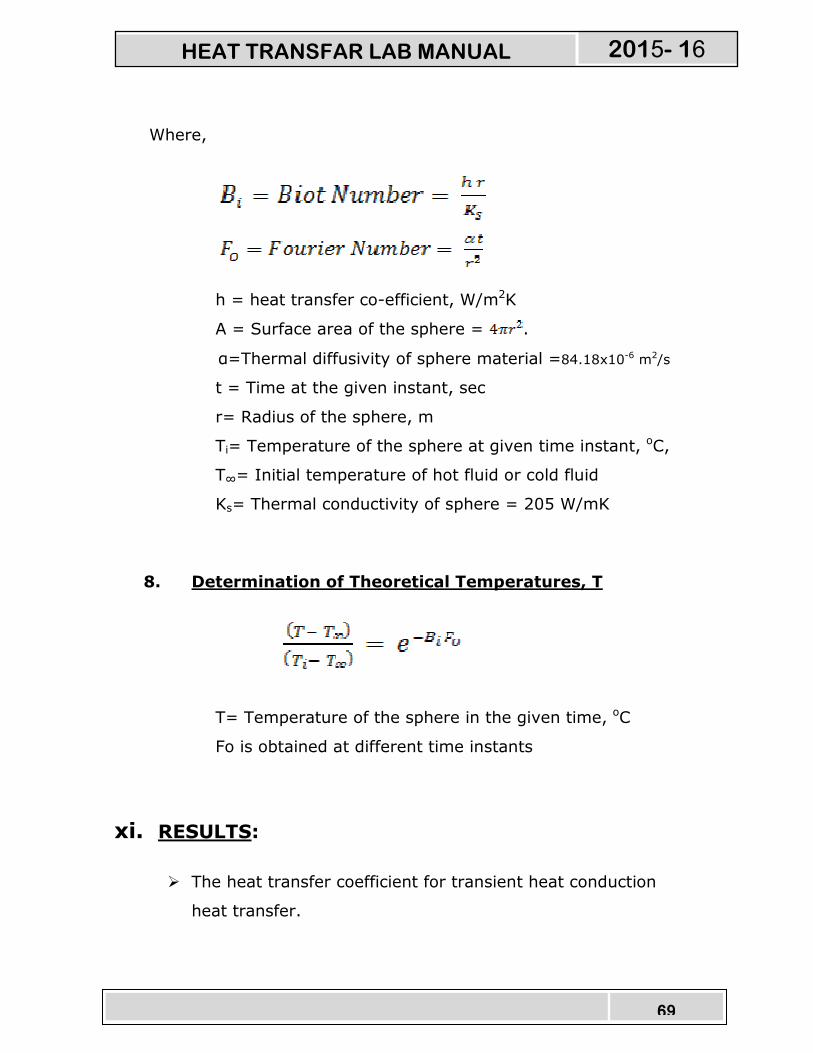
Where,
h = heat transfer co-efficient, W/m2K
A = Surface area of the sphere = .
α=Thermal diffusivity of sphere material =84.18x10⁻⁶ m2/s
t = Time at the given instant, sec
r= Radius of the sphere, m
Ti= Temperature of the sphere at given time instant, oC,
T∞= Initial temperature of hot fluid or cold fluid
Ks= Thermal conductivity of sphere = 205 W/mK
8. Determination of Theoretical Temperatures, T
T= Temperature of the sphere in the given time, oC
Fo is obtained at different time instants
xi. RESULTS:
� The heat transfer coefficient for transient heat conduction
heat transfer.
HEAT TRANSFAR LAB MANUAL 2015- 16

70
xii. GRAPHS:
� Experimental temperature v/s time,
� Theoretical temperature v/s time
4. PRECAUTIONS 4) Clean the tank regularly after every use.
5) Do not run the equipment if the voltage is below 180V.
6) Check all the electrical connections before running.
4) Do not attempt to alter the equipment as this may cause
damage to the whole system.
HEAT TRANSFAR LAB MANUAL 2015- 16

71
HEAT PIPE DEMONSTRATION
INTRODUCTION:
One of the main objectives of energy conversion systems is to
transfer energy from a receiver to some other location where it can be
used to heat a working fluid. The heat pipe is a novel device that can
transfer large quantities of heat through small surface areas with small
temperature differences. Here in this equipment an attempt has been
made to show the students, how the heat pipe works with different
methods.
DESCRIPTION OF THE APPARATUS:
The apparatus consists of a Solid Copper Rod of diameter (d)
25mm and length (L) 500mm with a Source at one end and condenser
at other end.
Similarly, Hollow copper pipe without wick and with wick
(SS mesh of 180microns) with same outer dia and length is
provided.
Thermocouples are fixed on the tube surface with a phase
angle of 90° on each pipe.
HEAT TRANSFAR LAB MANUAL 2015- 16
72
Contol panel instrumentation consists of:
g. Digital Temperature Indicator with channel selector.
h. Digital Voltmeter & Ammeter for power
measurement.
i. Heater regulator to regulate the input power.
With this, the setup is mounted on an aesthetically designed MS
Powder coated frame with MOVAPAN Board control panel to monitor all
the processes considering all safety and aesthetics factors.
EXPERIMENTATION:
AIM:
To determine the axial heat flux in a heat pipe using water as
the working fluid with that of a solid copper with different
temperatures.
PROCEDURE:
29. Provide the necessary electrical connection and then
CONSOLE ON switch.
30. Switch on the heater and set the voltage (say 40V) using
heater regulator and the digital voltmeter.
31. Wait for sufficient time to allow temperature to reach
steady values.
32. Note down the Temperatures 1 to 6 using the channel
selector and digital temperature indicator.
33. Note down the ammeter and voltmeter readings.
34. Calculate the axial heat flux for all the pipes.
35. Repeat the experiment for different heat inputs and
compare the results.
HEAT TRANSFAR LAB MANUAL 2015- 16
73
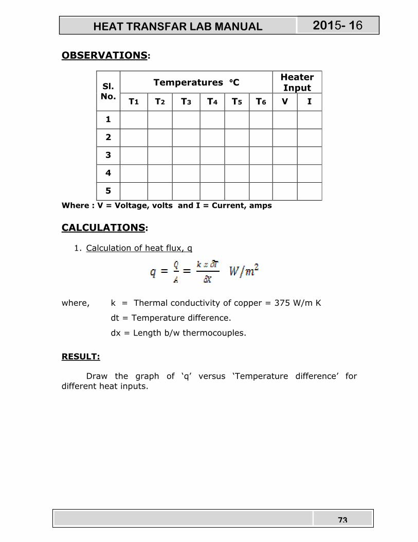
OBSERVATIONS:
Sl.
No.
Temperatures °°°°C Heater Input
T1 T2 T3 T4 T5 T6 V I
1
2
3
4
5
Where : V = Voltage, volts and I = Current, amps
CALCULATIONS:
1. Calculation of heat flux, q
where, k = Thermal conductivity of copper = 375 W/m K
dt = Temperature difference.
dx = Length b/w thermocouples.
RESULT:
Draw the graph of ‘q’ versus ‘Temperature difference’ for
different heat inputs.
HEAT TRANSFAR LAB MANUAL 2015- 16
74
Reference:
23. Heat and Mass transfer by Arora & Domkundwar
24. Chemical Engineers’ Handbook, by
Robert H. Perry / Cecil H. Chilton Publication: McGraw – Hill Book Company (6th edition)
PRECAUTIONS: 47. Check all the electrical connections.
48. Do not run the equipment if the voltage is below 180V.
49. Make sure that heater regulator is at the minimum position
before switching on the console.
50. Do not attempt to alter the equipment as this may cause
damage to the whole system.
HEAT TRANSFAR LAB MANUAL 2015- 16


