COMMUNICATIONS WITHIN A COMPUTER INTEGRATED MANUFACTURING ENVIRONMENT by Girish Nair Project Report submitted to the Faculty of the Virginia Polytechnic Institute and State University, in partial fulfillment of the requirements for the degree Master of Engineering in Industrial Engineering and Operations Research APPROVED: Hi Dr. M. P. Deisenroth (Chairman) LLM Dr. E. C. DeMeter Dr. R. J. Reasor June 1990 Blacksburg, Virginia.
Transcript
COMMUNICATIONS WITHIN A
COMPUTER INTEGRATED MANUFACTURING ENVIRONMENT
by
Girish Nair
Project Report submitted to the Faculty of the Virginia Polytechnic Institute and State University,
in partial fulfillment of the requirements for the degree Master of Engineering
in Industrial Engineering and Operations Research
APPROVED:
Hi Dr. M. P. Deisenroth (Chairman)
LLM Dr. E. C. DeMeter Dr. R. J. Reasor
June 1990
Blacksburg, Virginia.
LD 5655 V8 DS}
1490 N 347
CZ
COMMUNICATIONS WITHIN A
COMPUTER INTEGRATED MANUFACTURING ENVIRONMENT
by
Girish Nair
Dr. Michael P. Deisenroth, Committee Chairman
Industrial and Systems Engineering
(ABSTRACT)
In a computer integrated manufacturing (CIM)
environment, efficient data exchange and real-time error
recovery are required in order to provide a flexible and
reliable system. Adoption of a distributed processing
network, with several locally intelligent devices, helps
satisfy these requirements of CIM. Distributed processing
necessitates that computers have the ability to communicate
with the following: users, intelligent machines and devices,
and with other computers themselves.
In a flexible manufacturing system (FMS) involving
processing and interactions between several devices,
communication problems often occur. This project is
directed at providing test and debug capability for the
various devices within the FMS described below.
Additionally, it provides a demonstration of the various
interactions between the devices, both in a primitive and an
integrated state. For the primitive state, software tools
to test the functional status were developed. These tools
make the lower level communications transparent to the
users, who need be concerned only with their operation.
Briefly, the FMS under consideration is comprised of
three function based workcells - for the machining, assembly
and material handling functions of the system. Each
workcell has under its domain equipment needed to achieve
its respective function. The devices in the system include
IBM robots, DYNA CNC machines, a conveyor, a programmable
logic controller (PLC), and other cell controllers. The FMS
is to be used as a demonstration vehicle for students, to
teach fundamental principles of system integration and
control.
ACKNOWLEDGEMENTS
This work is dedicated to my parents in gratitude for
their constant love, support and encouragement. I have
achieved everything I have through their blessings.
To Dr. M. P. Deisenroth, my advisor, thank you for
introducing me to the world of automation. It has been a
learning experience working with you.
I would like to thank Dr. R.J. Reasor and Dr. E.C.
DeMeter for serving on my committee.
I would also like to thank my sisters and brothers -
in-law for their constant moral support and encouragement.
I would also like to thank my friend C.K.
Muralikrishnan, for all his suggestions. Finally, to my
friend and roommate Vishwanath Tirupattur for being there,
through high and low. I can’t thank you enough.
iv
TABLE OF CONTENTS
ABSTRACT
ACKNOWLEDGEMENTS
TABLE OF CONTENTS
LIST OF FIGURES
LIST OF TABLES
INTRODUCTION
PROBLEM STATEMENT and OBJECTIVES
LITERATURE REVIEW
CIM and Cell control
Control hierarchies Previous relevant work at VPI&SU
SYSTEM DESCRIPTION
FMS operations
METHODOLOGY
TOOLKIT FUNCTIONS
LAN communications Serial communications Robot primitives CNC primitives Digital I/O routines for DATA TRANSLATION board Digital I/O routines for DIO64 board
MACHINING WORKCELL
Hardware
Software
ASSEMBLY WORKCELL
Hardware
Software
MATERIAL HANDLING WORKCELL
Hardware
vil
1x
20
25 29 32 38 50 53 57
60 60 65
80 80 81
88 88
Software 90
10. SYSTEMS CONTROL 95
11. CONCLUSIONS & RECOMMENDATIONS 103
REFERENCES 106
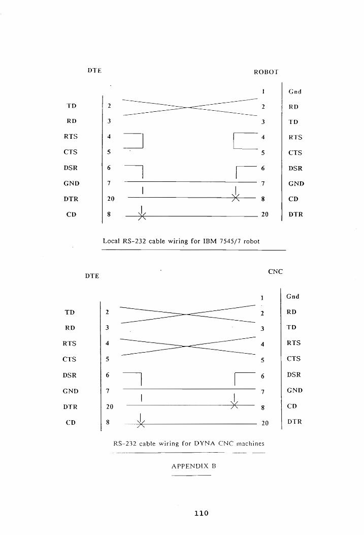
APPENDIX A - Procedure to load multiplexer device driver 109 B ~- Robot and CNC RS-232 cable configurations 110
VITA 111
vi
LIST OF FIGURES
Title
NBS control hierarchy
FMS layout
LAN configuration
FMS hardwiring diagram
Communications in the CIM laboratory
Toolkit menu
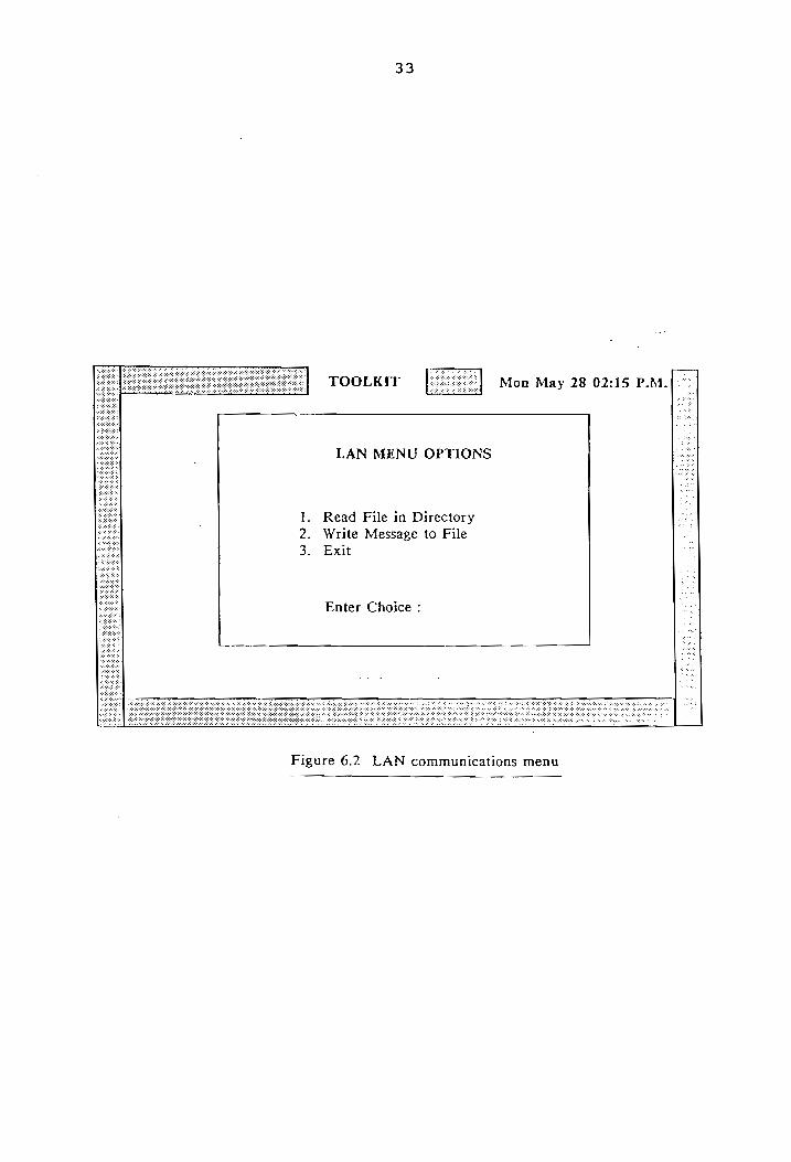
LAN communications menu
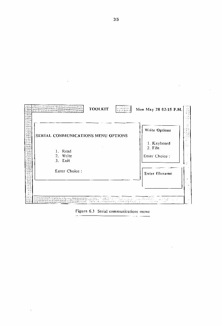
Serial communications menu
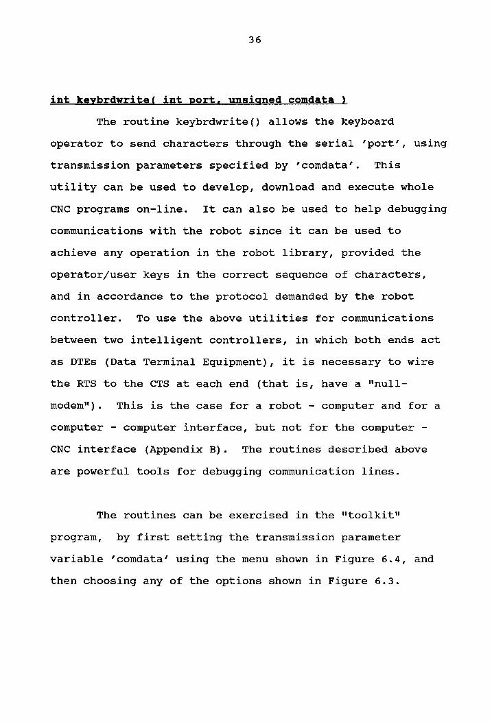
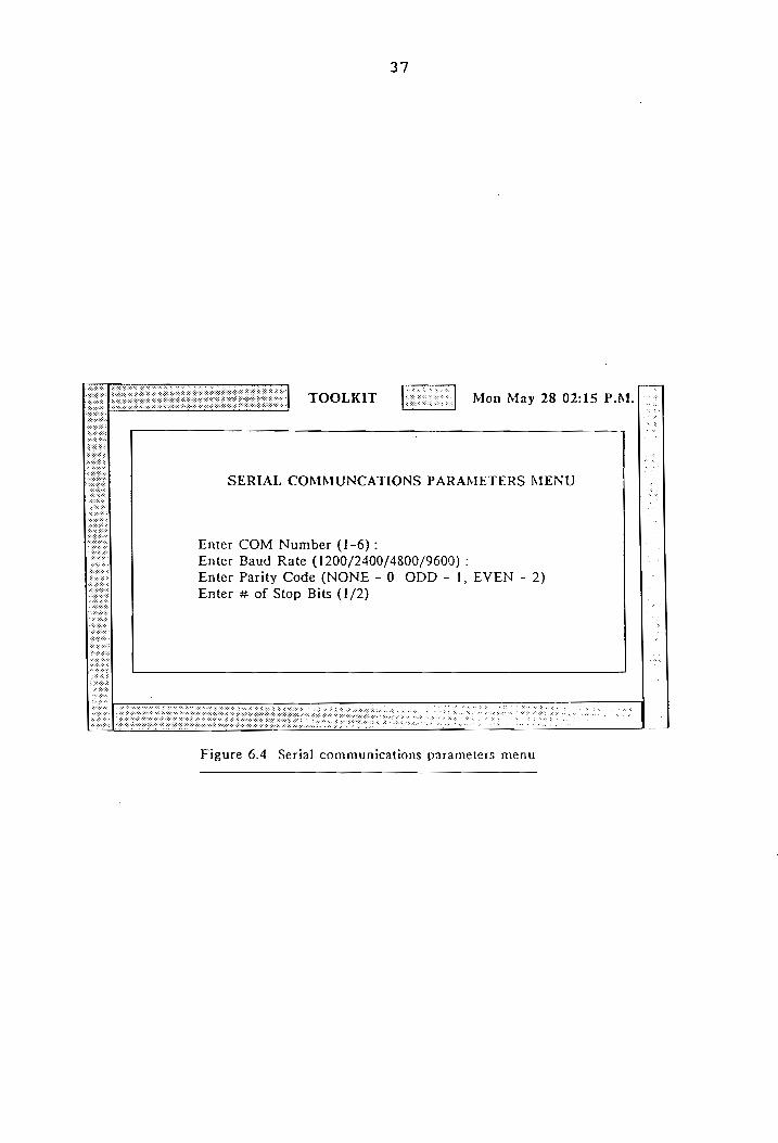
Serial communications parameters settings
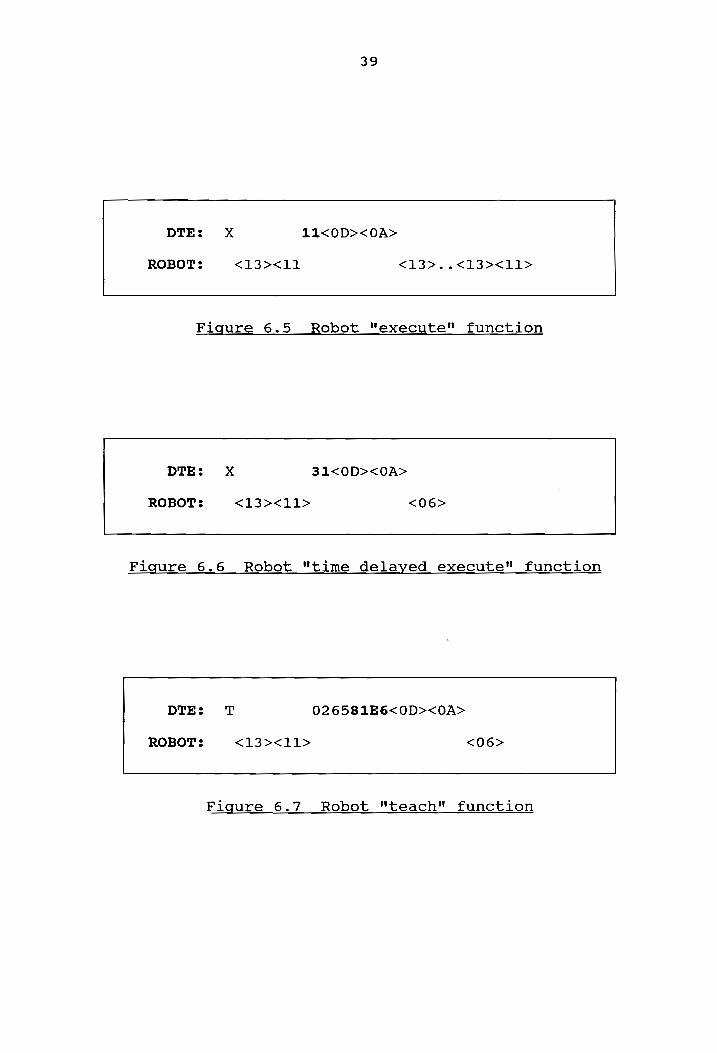
Robot "execute" function
Robot "time delayed execute" function
Robot "teach" function
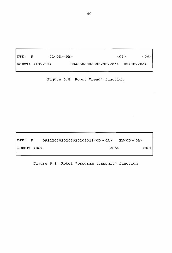
Robot "read" function
Robot "program transmit" function
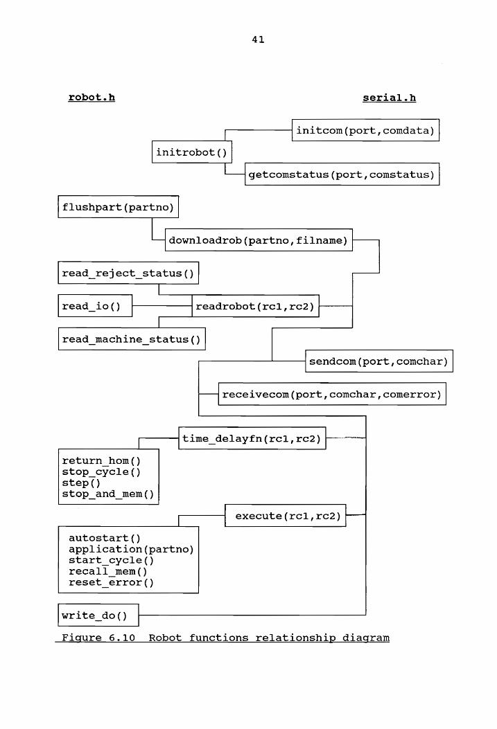
Robot functions relationship diagram
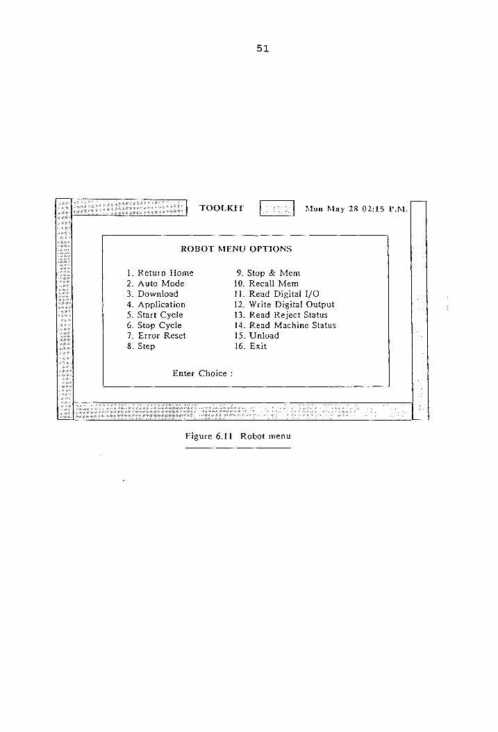
Robot menu
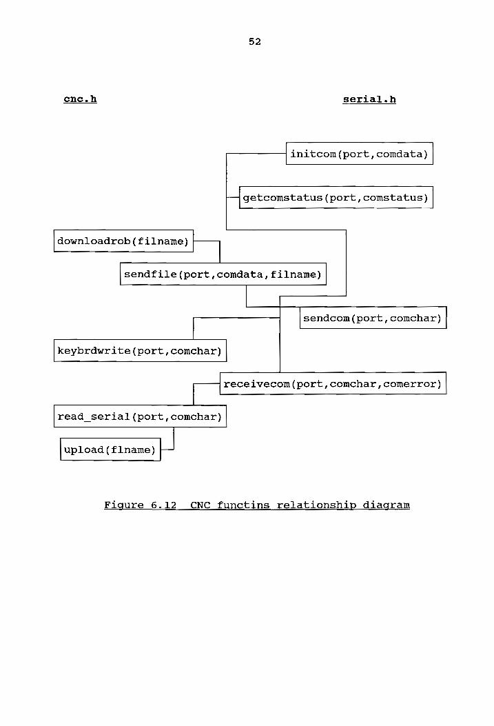
CNC functions relationship diagram
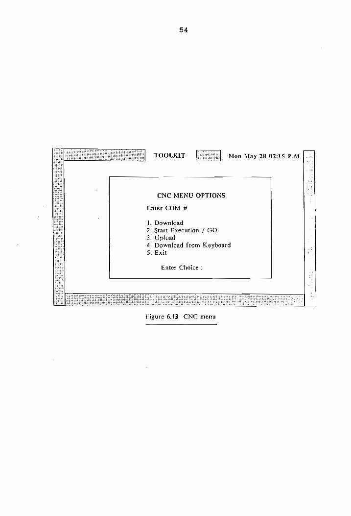
CNC menu
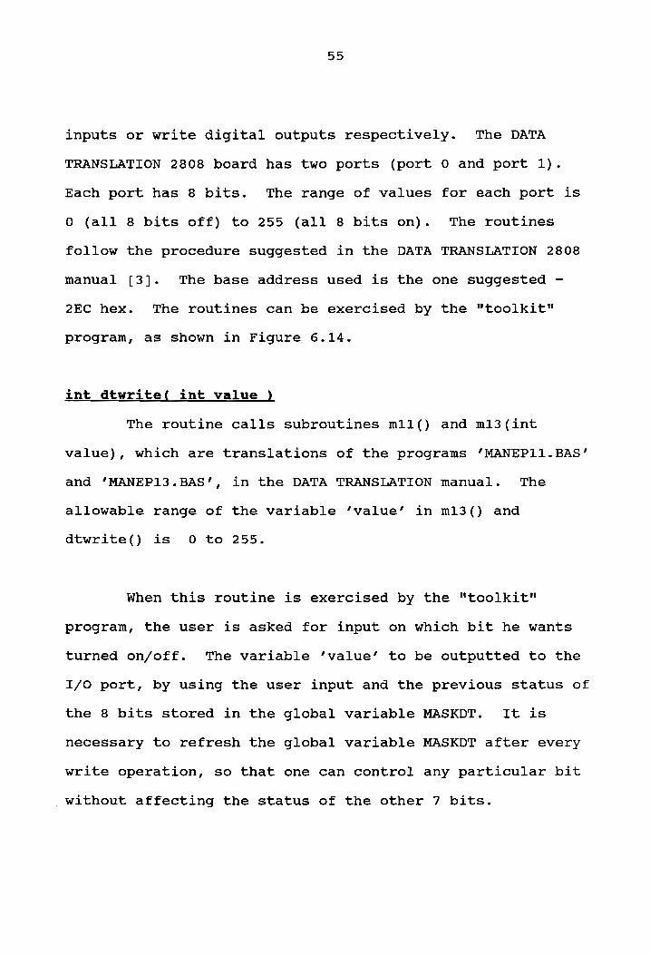
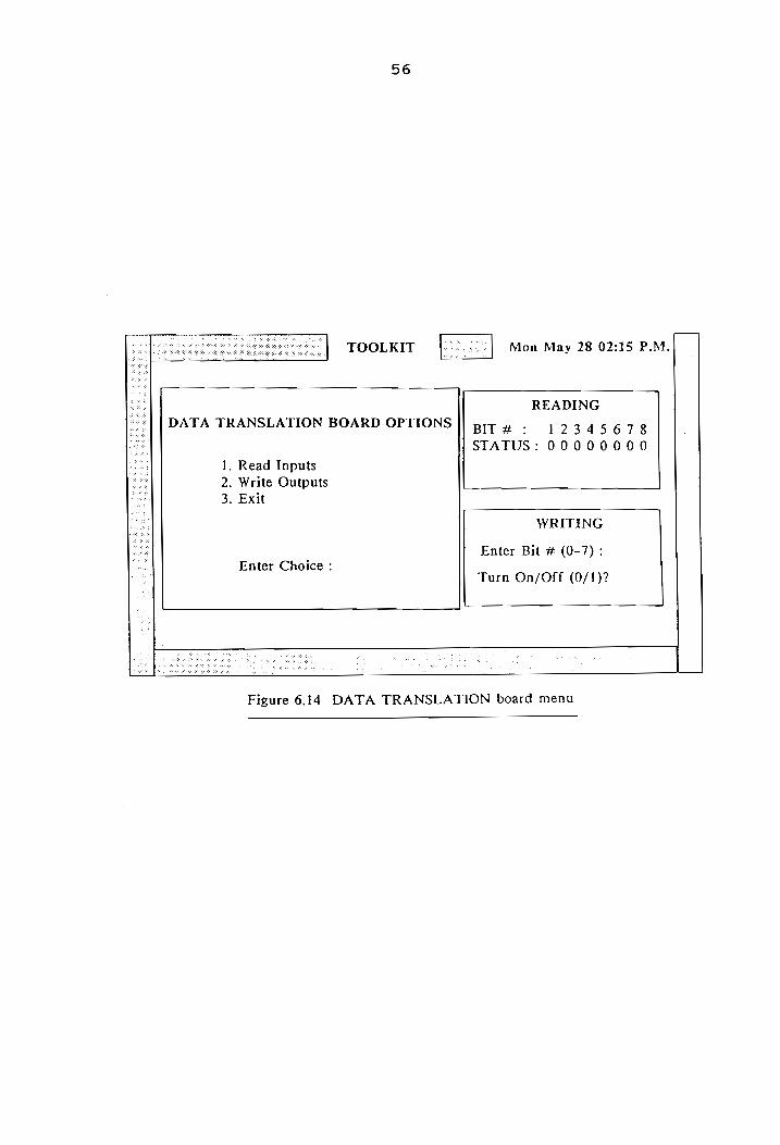
DATA TRANSLATION board menu
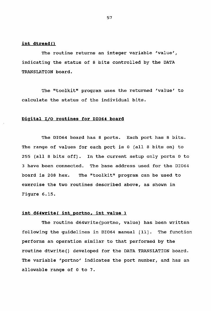
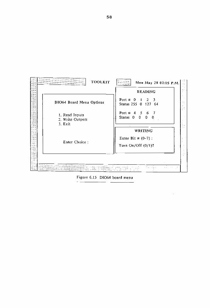
DI064 board menu
vil
13
14
17
18
30
33
35
37
39
39
39
40
40
41
51
52
54
56
58
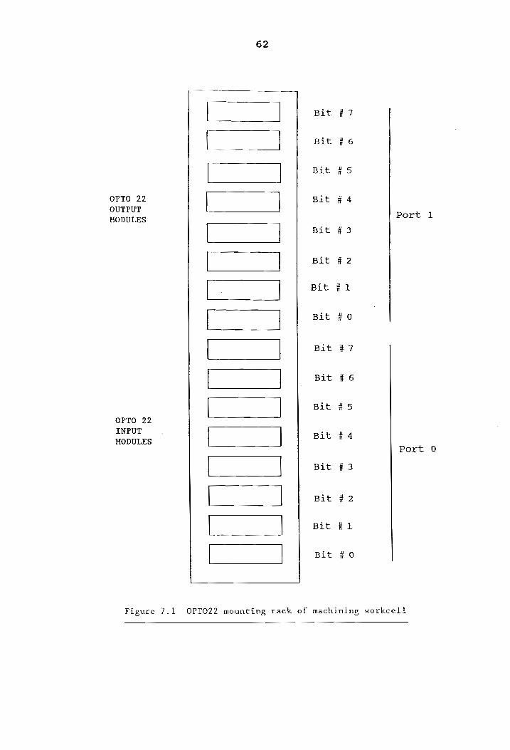
OPTO 22 mounting rack of machining workcell 62
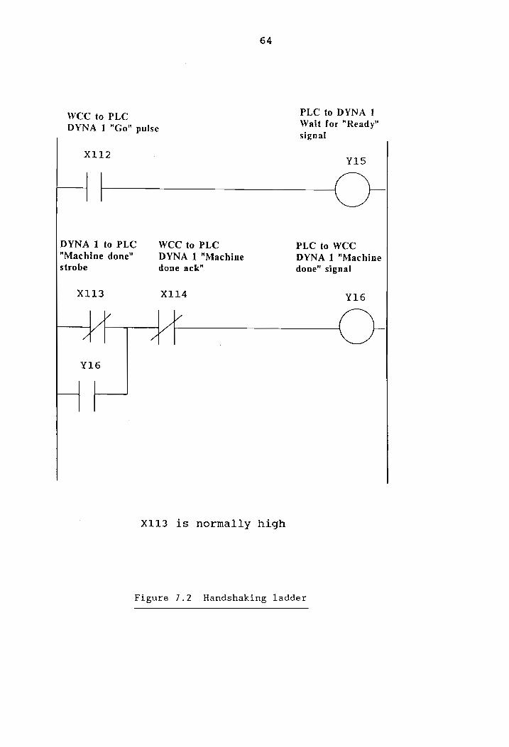
Handshaking ladder rungs 64
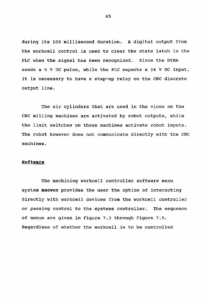
Machining workcell control options 66
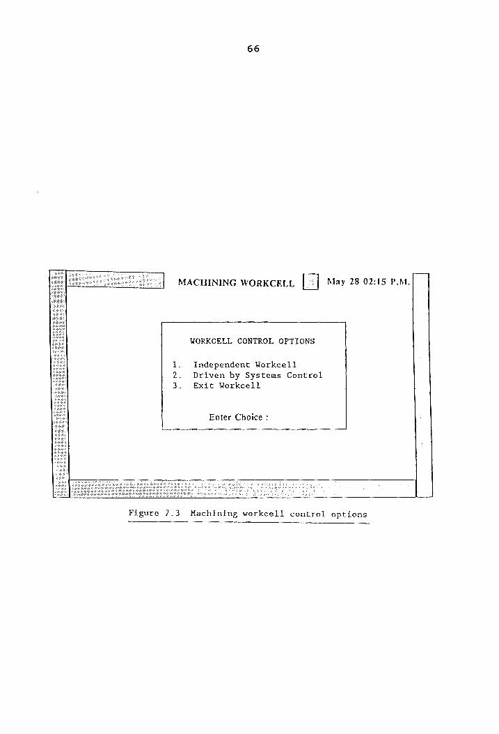
Machining workcell initialization menu 67
Machining workcell main menu 68
Assembly workcell control options 82
Assembly workcell initialization menu 83
Assembly workcell main menu 84
OPTO 22 mounting racks of material handling 89
Material handling workcell control options 91
Conveyor task menu 92
Systems control main menu 96
Vili
Table No.
10.1
10.2
10.3
LIST OF TABLES
Title
Test and debug capabilities (Augmenting toolkit)
System capabilities
Toolkit functions specifications
Typical handshake sequence
Robot and CNC supporting files for machining workcell
Breakdown of macro task ‘’mirobot’ of the machining workcell
System control commands to machining workcell
Robot supporting files for assembly workcell
System control commands to assembly workcell
System control commands to material handling workcell
Message files used by system control to communicate with cell controllers
Macros developed for systems control
Breakdown of super-macro task ’makerobot’ of the systems controller
1x
22
24
26
71
74
75
77
86
87
94
97
99
101
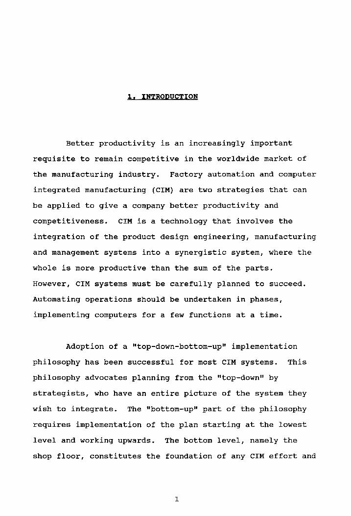
1. INTRODUCTION
Better productivity is an increasingly important
requisite to remain competitive in the worldwide market of
the manufacturing industry. Factory automation and computer
integrated manufacturing (CIM) are two strategies that can
be applied to give a company better productivity and
competitiveness. CIM is a technology that involves the
integration of the product design engineering, manufacturing
and management systems into a synergistic system, where the
whole is more productive than the sum of the parts.
However, CIM systems must be carefully planned to succeed.
Automating operations should be undertaken in phases,
implementing computers for a few functions at a time.
Adoption of a "top-down-bottom-up" implementation
philosophy has been successful for most CIM systems. This
philosophy advocates planning from the "top-down" by
strategists, who have an entire picture of the system they
wish to integrate. The "bottom-up" part of the philosophy
requires implementation of the plan starting at the lowest
level and working upwards. The bottom level, namely the
shop floor, constitutes the foundation of any CIM effort and
is the level at which any implementation should begin. When
operational, the next hierarchical level in the organization
is addressed. This upward and outward implementation
methodology, can be done in a step by step fashion, with
system integration being achieved as the modules are
automated.
A flexible manufacturing system (FMS) can be defined
as a group of automated machine tools that are
interconnected by means of a material handling and storage
system, and which operates as an integrated system under
computer control [18]. Most manufacturers define an FMS
cell (or workcell) as the smallest building block of an FMS.
An FMS cell has under its domain one or more devices, like
robots, CNC machines, inspection and/or material handling
equipment. The devices themselves are under the control of
a reprogrammable workcell controller (WCC). The WCCs
themselves can be under the control of higher level
supervisory controllers.
There are many factors to be considered during CIM
implementation. During the design of an FMS within a CIM
environment, the software control strategy, the physical and
electrical configurations have to be decided. Floor space
constraints, the work envelopes of the different devices,
the maximum allowable length of cables for various
communications, the minimization and ease of material
handling, operator interface and safety considerations are
factors influencing the physical configuration and layout of
the system.
2. PROBLEM STATEMENT AND OBJECTIVES
A flexible manufacturing system (FMS) is normally
divided into smaller workcells, each of which consist of a
variety of equipment built by different manufacturers.
Since vendors of automation equipment have no standard code
to which they have to adhere, integrating these machines
under a flexible manufacturing environment becomes a problem
[9]. An FMS requires the integration and coordination of a
diverse group of machines, each operating on a different
protocol and configuration. In systems which involve a
large number of interfaces between devices and require
synchronization of tasks, it is necessary to have a parallel
intelligent device like a programmable logic controller
(PLC), interfacing with the devices and the cell
controllers.
Another problem found in systems which involve a
large number of interfaces between devices, is that the
amount and complexity of the communications that are
necessary can become overwhelming. In order to have a
flexible and reliable system, it is imperative to be able to
test and debug the functional status of the communication
links within the systen.
There were two objectives of this research. The
primary objective was to develop a test and debug capability
for the communication links within the FMS under
consideration. Software tools to test the functional status
of the system were developed, towards meeting this
objective. In other words, the tools developed can be used
to check the hardwire continuity of the system. The second
objective was to demonstrate the applicability of primitive
communications to achieve high level operations required for
an integrated and automated system.
3. LITERATURE REVIEW
Having a manufacturing edge in the marketplace is
primarily determined by the efficiency and quality of the
whole manufacturing process. In today’s changing market
however, flexibility has become an increasingly important
requisite for corporations to remain competitive.
Incorporating flexible automation and CIM is a solution to
these problems.
CIM and Cell Control
CIM has been defined as a method of providing
computer assistance, control and high level integrated
automation at all levels of the manufacturing industry, by
linking “islands of automation" or cells, into a distributed
processing system [1]. Each cell can be comprised of one or
more devices, like robots, CNC machines, conveyors, vision
systems, coordinate measuring machines and/or AGVs, under
the control of a cell controller.
One of the fundamental services of a cell controller,
is the control and execution of activities of the devices
within the cell, in a desired activity sequence. Real time
predictability must be maintained by the cell controller,
for situations requiring synchronized coordination of device
activities. The cell controller can ensure real time
synchronization between the devices under its control, by
incorporating a predetermined handshake policy.
Current cell controller offerings generally serve as
system integrator’s toolkits, and as such, are composed
primarily of software utilities [14]. However, in order to
implement CIM successfully, three types of integration are
required - electronic, physical and organizational [5].
Manufacturers have failed to realize that in attempting to
tie together and control computerized processes, they need
to establish a control hierarchy [7].
Control Hierarchies
In order to achieve flexibility and modularity in an
advanced manufacturing system, a well defined control
strategy is necessary. There are many control strategies,
the most popular of which are the hierarchical control model
developed by the National Bureau of Standards (NBS) for
their Automated Manufacturing Research Facility (AMRF), and
the DEC/Philips control system model.
In order to meet the requirements of real time
production, the NBS hierarchical control system [14], has
been:
1) partitioned into a hierarchy in which the control
processes are isolated by function and communicate
via standard interfaces,
2) designed to respond in real time, to performance
data, derived from machines equipped with sensors,
3) implemented in a distributed computer environment,
using recent advances in software and hardware
engineering.
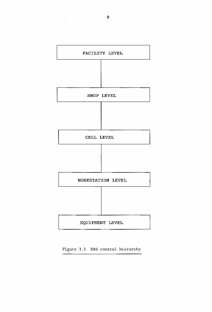
The NBS system architecture is a command/feedback
control structure composed of five major levels: facility,
shop, cell, workstation and equipment (Figure 3.1). This
configuration ensures that the size, functionality and
complexity of individual control modules are limited.
The DEC/Philips model of a controller [5], on the
other hand, has access to local and global data and commands
from the controller above it. The model issues commands to
the subordinate controllers and receives sensory input from
FACILITY LEVEL
SHOP LEVEL
CELL LEVEL
WORKSTATION LEVEL
EQUIPMENT LEVEL
Figure 3.1 NBS control hierarchy
10
them. The three major functions performed are task
decomposition, sensory data processing, representation,
storage and retrieval.
Previous Relevant Work at VPI&SU
As mentioned previously, the development of a CIM
system can be executed in stages, implementing a few
functions at a time. This is the manner in which the
development and implementation of the FMS in the CIM
facility at VPI&SU has been undertaken. Previous work
includes:
1) Development of a basic set of macros, by Guleri [9],
which permit communications between the workcell
controller and the robots and the CNC machines.
Primitive routines to receive and send data from
serial ports, and macros to download to the CNC
machine was developed by Guleri. The macros
developed for the robot included the ability to
send the robot "home", set the robot controller to the
"auto" mode, download files, select partitions and
start and stop the robot cycle.
2) Development of software menu system/workcell
controller programs in graduate class group projects,
namely Saboo et al. (Systems Control) [21], Romano et
11
al. (Machining) [20], Nair et al. (Assembly) [16] and
Ridgway et al. (Material Handling) [19].
3) Development of a Relay ladder logic (RLL) control
program to drive the material handling workcell,
developed by Bidani [1] and modified by Muralikrishnan
et al. [15]. This program executes different conveyor
tasks, depending on the task code it receives from the
workcell controller.
4) Development of a simulated intelligent shopfloor
control system by Zhang [23].
The first phase of this project, namely building a
test and debug capability for the FMS under consideration,
used the toolkit developed by Guleri [9] as a basis. The
software written for the three workcells and the system
controller [15,16,19,20,21] was used as a basis for the
development of the integrated FMS software.
4. SYSTEM DESCRIPTION
The CIM laboratory at the Department of Industrial
and Systems Engineering at the Virginia Polytechnic
Institute and State University, houses an FMS which serves
to provide instruction and research facilities in computer
control and integration of manufacturing systems. The
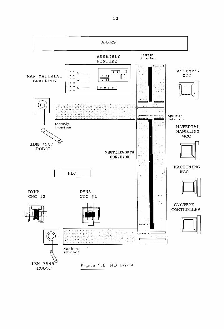
entities within the laboratory (Figure 4.1) are two IBM
robots, two three-axis CNC milling machines, a conveyor
system, an automatic storage and retrieval system (AS/RS), a
TI 565 programmable controller, a GE Optomation vision
system, fixtures, sensors, actuators, pallets, a vibratory
bowl feeder, and four AT&T personal computers,
interconnected by a STARLAN local network. STARLAN uses a
star configuration in which all computers communicate
directly with the central computer or file server, which is
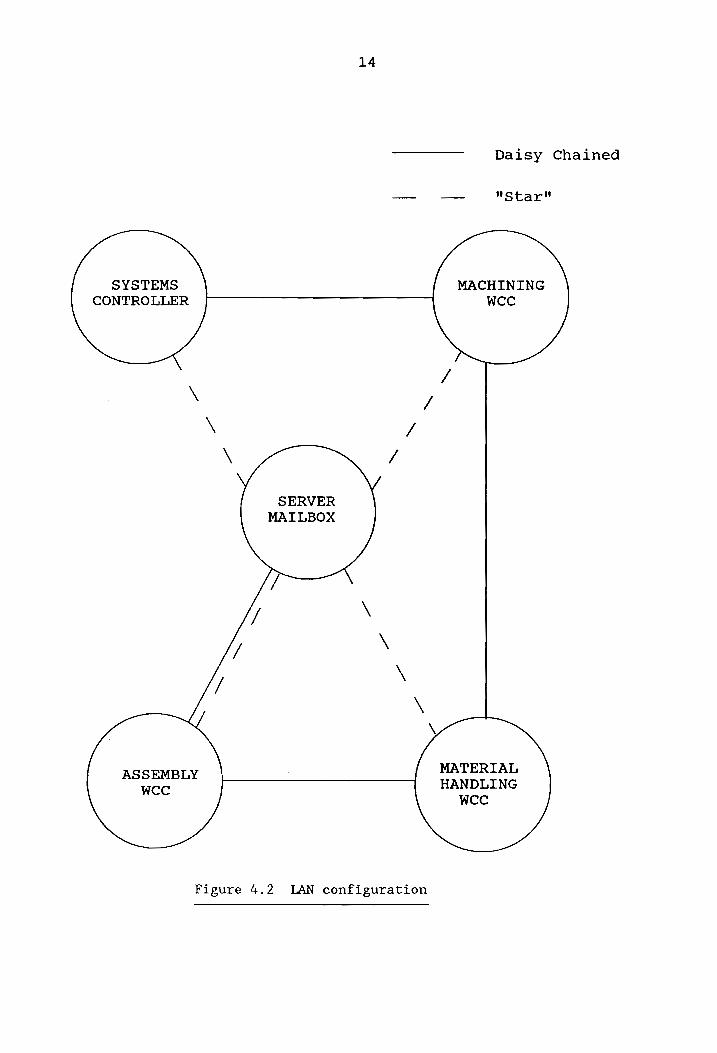
the fifth computer in the network. The computers may also
be "daisy chained" to achieve communications, as shown in
Figure 4.2. This is how the computers have been linked to
each other in the CIM laboratory. The network has a 1
megabit per second data transmission speed. Note that the
server is not to be confused with the systems controller
12
13
AS/RS
Storage ASSEMBLY interface
FIXTURE
. FI - ASSEMBLY
RAW MATERIAL | *° 5 (4 mee BRACKETS ea
Bos — er oe 7 | Operator
Si a S| interface
Assembly . nr interface MATERIAL
HANDLING
WCC
IBM 7547
ROBOT
SHUTTLEWORTH
CONVEYOR
MACHINING
PLC WCC
DYNA DYNA
CNC #2 CNC #1
Ti SYSTEMS CONTROLLER
Cee
. foe ———
O Ue —,
Machining interface
IBM 7545 Figure 4.1 FMS layout ROBOT
14
Daisy Chained
—_ — "Star"
SYSTEMS MACHINING CONTROLLER wcec
/ \ /
\ /
\ /
SERVER
MATLBOX
\
\
\
\
MATERIAL ASSEMBLY HANDLING
wcc wee
Figure 4.2 LAN configuration
15
(Figure 4.2). Each computer reads from and writes messages
to a common directory or "mailbox" on the server.
The system was originally designed for discrete part
batch manufacture of two products - miniature wax SCARA
robots and milling machines. A third product, a keychain,
was added this academic year. Different products can be
manufactured by changing the fixtures appropriately and
altering the control sequence software. Final redesign of
the fixtures was done by Wiegmann et al. [22] for the
machining workcell, and Economy et al. [6] for the assembly
workcell.
Conceptually, the development and implementation of
the lowest two layers, and part of the third layer of the
NBS control hierarchy, namely, the equipment, the cell and
the system levels, defines the scope of this project. The
systems controller provides overall control of the system.
It basically acts as a commander and coordinator of
operations at the cell level. Ideally, a systems controller
consists of a task manager and a resource manager module
[13]. The task manager is responsible for planning
capacity, grouping orders into batches, assigning and
releasing batch jobs to cells, allocating resources to
cells, tracking individual orders to completion, and report
16
generation. The resource manager on the other hand,
allocates production resources according to the optimization
algorithm chosen. Only the task manager will be implemented
by this project, without any elaborate scheduling features.
The tasks will be performed in a pre-determined sequence -
the capability to prioritize tasks is beyond the scope of
this project.
There are three cell controllers - for the machining,
assembly and material handling cells respectively. A
detailed description of the equipment and hardware
configurations in the workcells as well as software routines
developed for the workcell controllers and the systems
controller are given in later chapters. The software
routines call primitives developed as part of the toolkit.
Error conditions in the case of all three workcells
are indicated by digital outputs readable to the
programmable controller. This helps in status monitoring
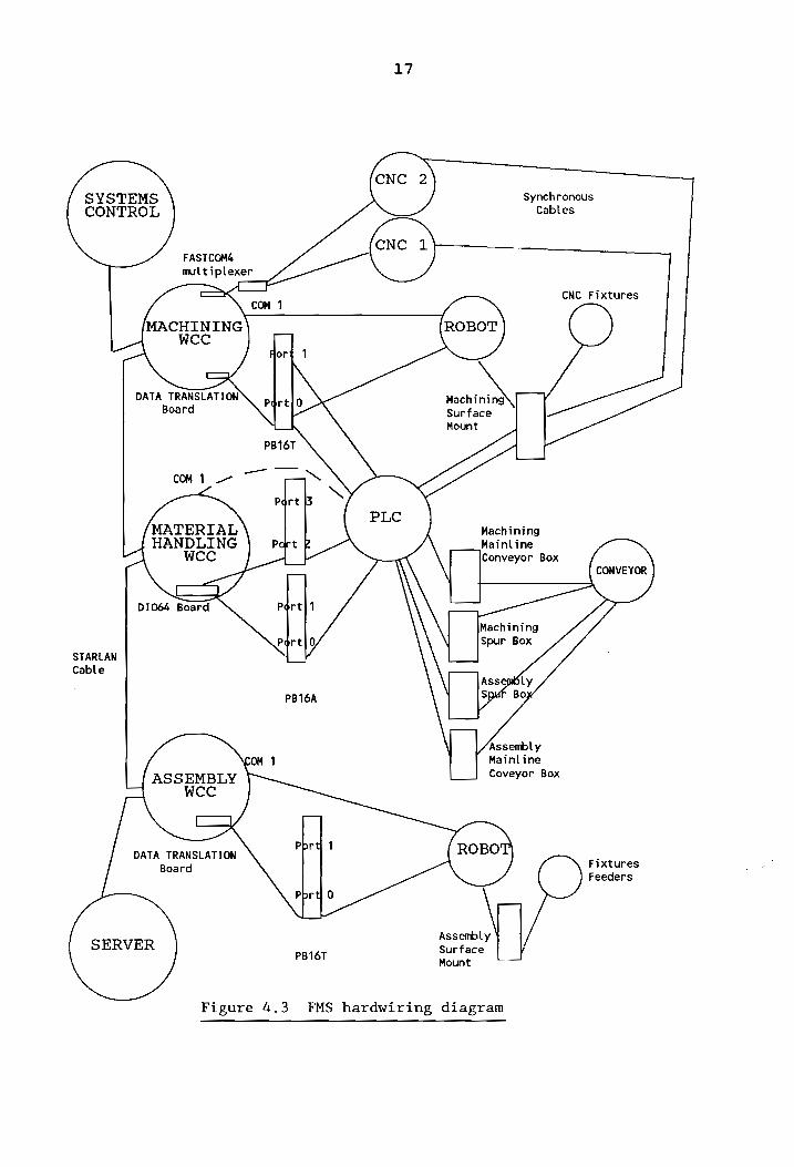
and debugging of the system. The CIM laboratory cable
documentation [2] gives complete information of the cabling
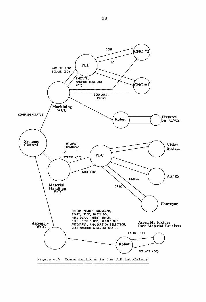
configuration in the present system. Figure 4.3 gives the
FMS hardwiring diagram, and Figure 4.4 depicts the
Assembly AUTOSTART, APPLICATION SELECTION, WCC READ MACHINE & REJECT STATUS
Assembly Fixture Raw Material Brackets
SENSORS(DI) CY
Robot )
ACTUATE (DO)
Figure 4.4 Communications in the CIM laboratory
19
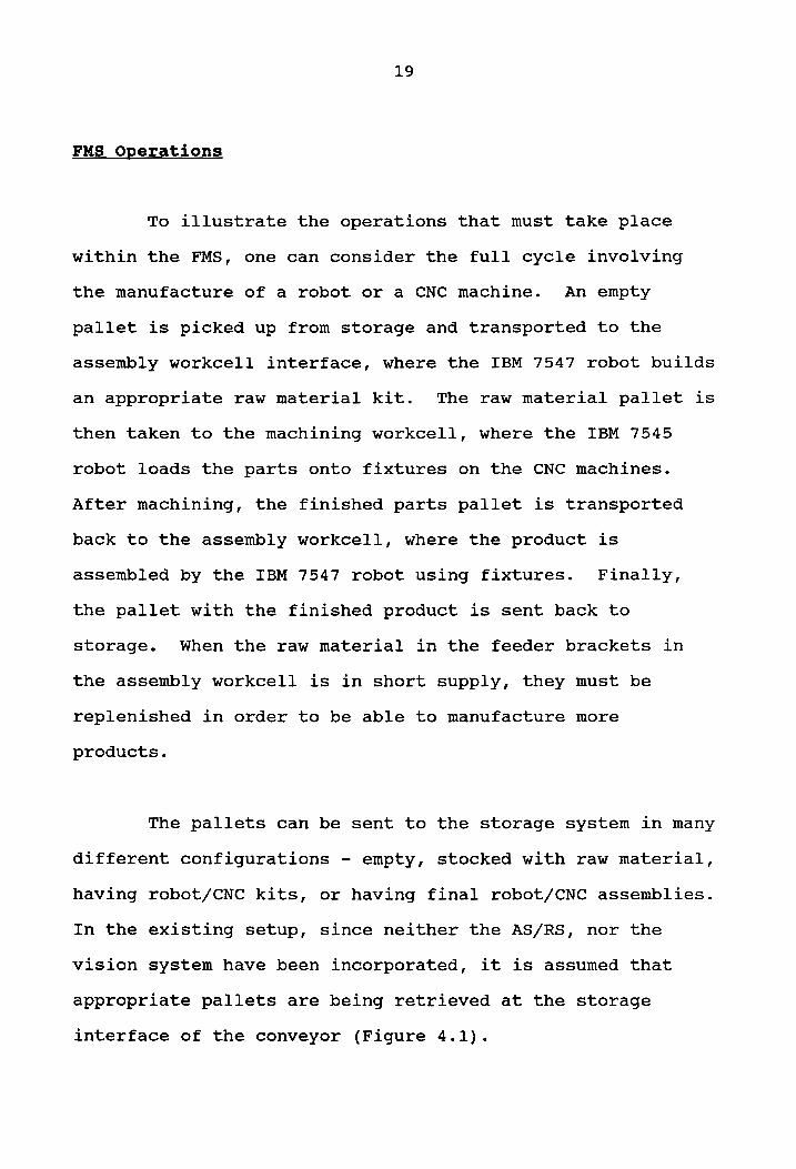
FMS Operations
To illustrate the operations that must take place
within the FMS, one can consider the full cycle involving
the manufacture of a robot or a CNC machine. An empty
pallet is picked up from storage and transported to the
assembly workcell interface, where the IBM 7547 robot builds
an appropriate raw material kit. The raw material pallet is
then taken to the machining workcell, where the IBM 7545
robot loads the parts onto fixtures on the CNC machines.
After machining, the finished parts pallet is transported
back to the assembly workcell, where the product is
assembled by the IBM 7547 robot using fixtures. Finally,
the pallet with the finished product is sent back to
storage. When the raw material in the feeder brackets in
the assembly workcell is in short supply, they must be
replenished in order to be able to manufacture more
products.
The pallets can be sent to the storage system in many
different configurations - empty, stocked with raw material,
having robot/CNC kits, or having final robot/CNC assemblies.
In the existing setup, since neither the AS/RS, nor the
vision system have been incorporated, it is assumed that
appropriate pallets are being retrieved at the storage
interface of the conveyor (Figure 4.1).
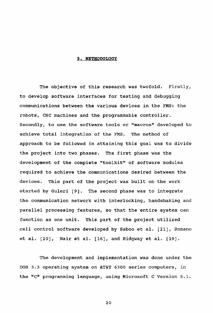
5. METHODOLOGY
The objective of this research was twofold. Firstly,
to develop software interfaces for testing and debugging
communications between the various devices in the FMS: the
robots, CNC machines and the programmable controller.
Secondly, to use the software tools or "macros" developed to
achieve total integration of the FMS. The method of
approach to be followed in attaining this goal was to divide
the project into two phases. The first phase was the
development of the complete "toolkit" of software modules
required to achieve the communications desired between the
devices. This part of the project was built on the work
started by Guleri [9]. The second phase was to integrate
the communication network with interlocking, handshaking and
parallel processing features, so that the entire system can
function as one unit. This part of the project utilized
cell control software developed by Saboo et al. [21], Romano
et al. [20], Nair et al. [16], and Ridgway et al. [19].
The development and implementation was done under the
DOS 3.3 operating system on AT&T 6300 series computers, in
the "Cc" programming language, using Microsoft C Version 5.1.
20
21
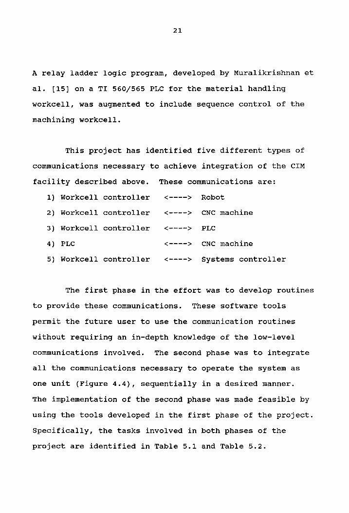
A relay ladder logic program, developed by Muralikrishnan et
al. [15] on a TI 560/565 PLC for the material handling
workcell, was augmented to include sequence control of the
machining workcell.
This project has identified five different types of
communications necessary to achieve integration of the CIM
facility described above. These communications are:
1) Workcell controller <----> Robot
2) Workcell controller <----> CNC machine
3) Workcell controller <----> PLC
4) PLC <----> CNC machine
5) Workcell controller <----> Systems controller
The first phase in the effort was to develop routines
to provide these communications. These software tools
permit the future user to use the communication routines
without requiring an in-depth knowledge of the low-level
communications involved. The second phase was to integrate
all the communications necessary to operate the system as
one unit (Figure 4.4), sequentially in a desired manner.
The implementation of the second phase was made feasible by
using the tools developed in the first phase of the project.
Specifically, the tasks involved in both phases of the
project are identified in Table 5.1 and Table 5.2.
22
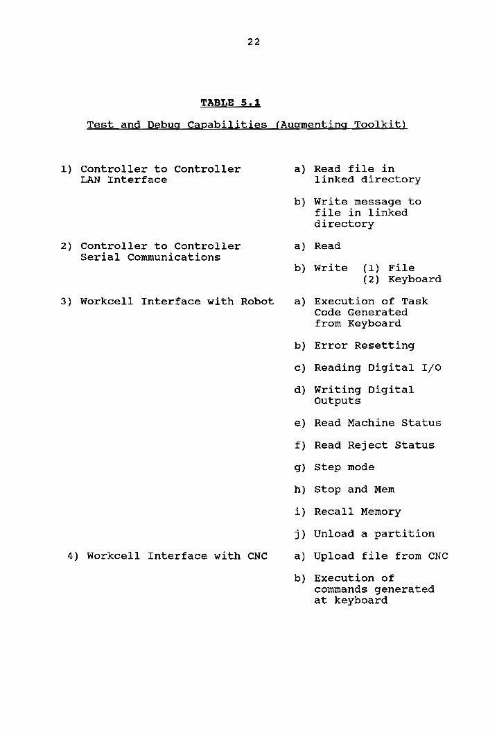
TABLE 5.1
Test and Debug Capabilities (Augmenting Toolkit)
1) Controller to Controller a) LAN Interface
b)
2) Controller to Controller a) Serial Communications
b)
3) Workcell Interface with Robot a)
4) Workcell Interface with CNC a)
b)
Read file in linked directory
Write message to file in linked directory
Read
Write (1) File (2) Keyboard
Execution of Task
Code Generated
from Keyboard
Error Resetting
Reading Digital I/oO
Writing Digital Outputs
Read Machine Status
Read Reject Status
Step mode
Stop and Mem
Recall Memory
Unload a partition
Upload file from CNC
Execution of commands generated at keyboard
23
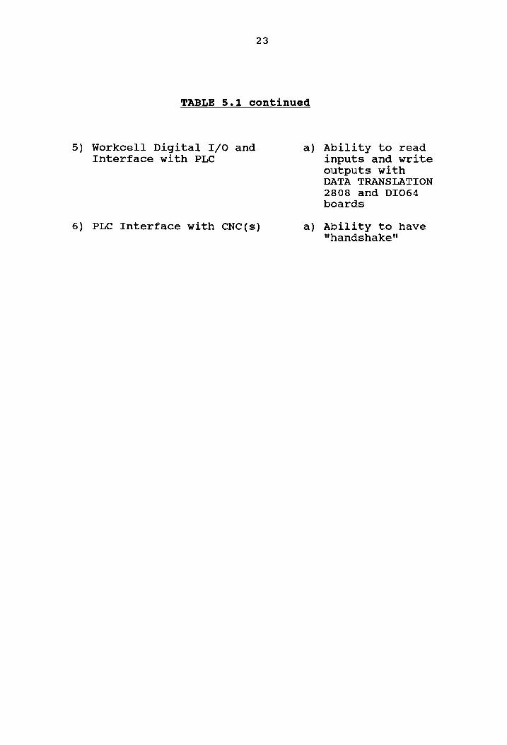
TABLE 5.1 continued
5) Workcell Digital I/O and a) Ability to read Interface with PLC inputs and write
outputs with DATA TRANSLATION
2808 and DI064
boards
6) PLC Interface with CNC(s) a) Ability to have "handshake"
1)
2)
3)
4)
5)
24
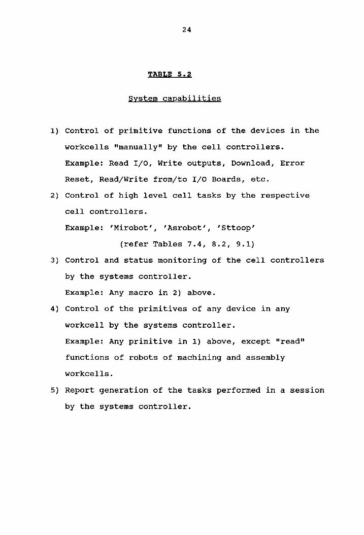
TABLE 5.2
System capabilities
Control of primitive functions of the devices in the
workcells "manually" by the cell controllers.
Example: Read I/O, Write outputs, Download, Error
Reset, Read/Write from/to I/O Boards, etc.
Control of high level cell tasks by the respective
cell controllers.
Example: ’Mirobot’, ‘’Asrobot’, ’Sttoop’
(refer Tables 7.4, 8.2, 9.1)
Control and status monitoring of the cell controllers
by the systems controller.
Example: Any macro in 2) above.
Control of the primitives of any device in any
workcell by the systems controller.
Example: Any primitive in 1) above, except "read"
functions of robots of machining and assembly
workcells.
Report generation of the tasks performed in a session
by the systems controller.
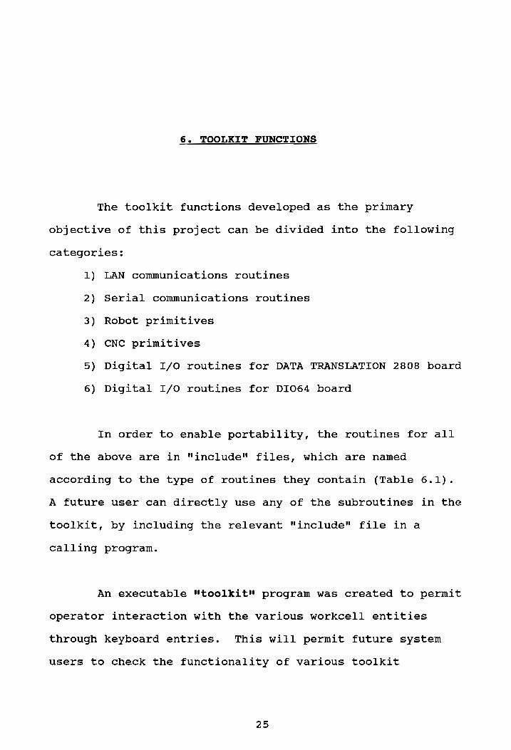
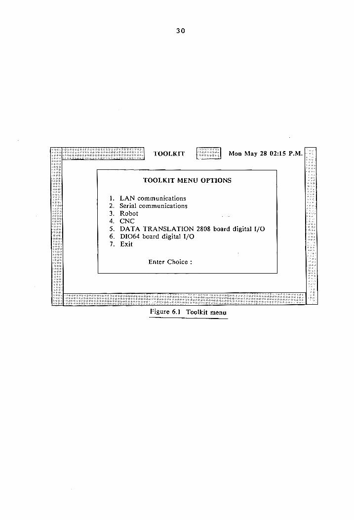
6. TOOLKIT FUNCTIONS
The toolkit functions developed as the primary
objective of this project can be divided into the following
categories:
1) LAN communications routines
2) Serial communications routines
3) Robot primitives
4) CNC primitives
5) Digital I/O routines for DATA TRANSLATION 2808 board
6) Digital I/O routines for DIO64 board
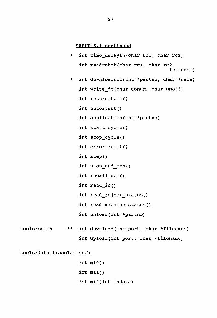
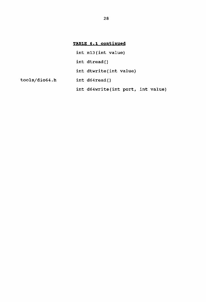
In order to enable portability, the routines for all
of the above are in “include" files, which are named
according to the type of routines they contain (Table 6.1).
A future user can directly use any of the subroutines in the
toolkit, by including the relevant "include" file ina
calling program.
An executable "toolkit" program was created to permit
operator interaction with the various workcell entities
through keyboard entries. This will permit future system
users to check the functionality of various toolkit
25
26
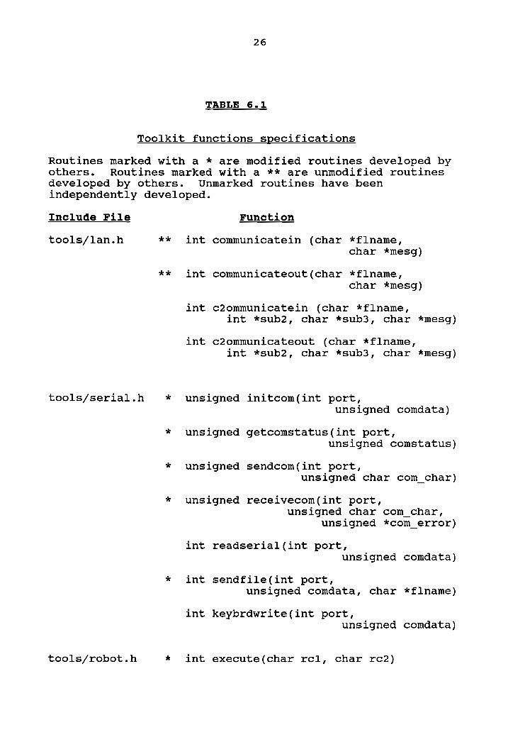
TABLE 6.1
Toolkit functions specifications
Routines marked with a * are modified routines developed by others. Routines marked with a ** are unmodified routines developed by others. Unmarked routines have been
independently developed.
Include File
tools/lan.h wx
kk
tools/serial.h *
tools/robot.h *
Function
int communicatein (char *flname, char *mesg)
int communicateout(char *flname, char *mesg)
int c2ommunicatein (char *flname, int *sub2, char *sub3, char *mesg)
int c2ommunicateout (char *flname, int *sub2, char *sub3, char *mesg)
Set to On-Line Set CNC to I Ready Set CNC to I Ready Hit any key Hit any key Hit any key
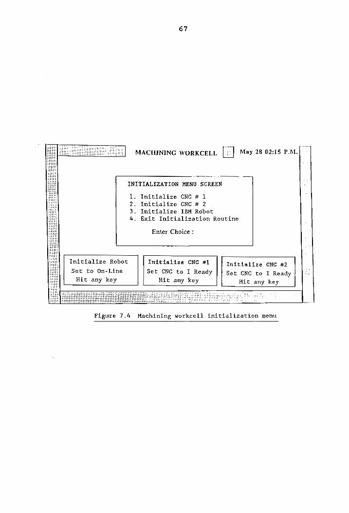
Figure 7.4 Machining workcell initialization menu
68
MACHINING WORKCELL [| May 28 02:15 P.M.
Main Menu
Machine Robot
Machine CNC machine
Equipment Control Exit W
he
Enter Choice
—
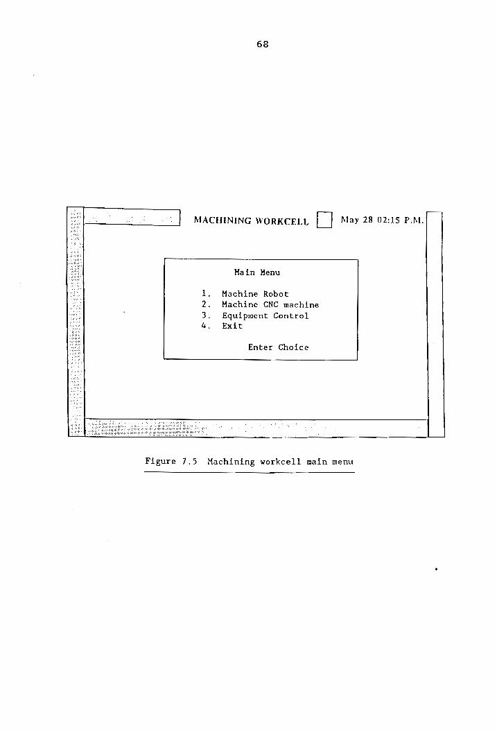
Figure 7.5 Machining workcell main menu
69
locally or via systems control, the user is first asked to
initialize the different pieces of equipment before
proceeding (Figure 7.4). In the case of the robot, this
involves sending it to the "home" position and placing the
robot controller in the "auto" mode. In the case of the CNC
machines, this involves manually setting up the machines to
receive programs and then establishing the origin of the
reference coordinate system. The respective routines used
to achieve the above tasks are return_home(), autostart()
and download(ncnumber, filename).
If the user chooses to run the workcell from the
local controller, three options are presented: machine a
robot, machine a CNC or perform primitive control of
equipment within the workcell. This is illustrated in
Figure 7.5. The routines developed for the above are
mirobot(), micnc(), and equipment(). The mirobot() and
micnc() routines are "macro" routines, which cause a
sequence of tasks to be initiated through communication
sequences between the workcell control and various workcell
devices. The routine equipment() provides a menu to access
the primitives of the robot or either CNC machine.
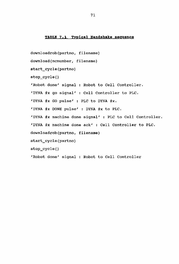
The typical sequence of operations and handshakes
involved in the machining workcell can be described by
70
considering the initial steps taken in the machining of a
wax CNC machine (Table 7.1). The cell controller downloads
a program, to load raw material onto the CNC machine, to the
robot controller. The execution of the program is then
started. After the CNC machines have been loaded, and the
robot has moved away to a safe position, the IBM 7545 robot
sends a ‘done’ signal to the cell controller. On receiving
this signal, the controller writes a digital output which is
picked up as an input by the PLC. The ladder logic in the
PLC ensures that the PLC then sends a synchronous pulse to
the DYNA CNC machine. The DYNA which all along had been
waiting for this ’GO’ signal, (at a CONTROL 3 statement),
then starts execution of the machining section of DYNA code.
After finishing machining, the DYNA sends back a synchronous
pulse to the PLC with a CONTROL 2 statement. The PLC then
indicates to the cell controller that the DYNA has finished
machining. The cell controller now "tells" the robot to go
and pick up the part from the CNC machine.
Handshakes between the different pieces of equipment
are necessary to ensure proper sequencing of parallel
operations by the different devices, after these operations
have completed. For example, it is necessary that the DYNA
machine start machining the part only after the robot has
71
TABLE 7.1 Typical Handshake sequence
downloadrob(partno, filename)
download(ncnumber, filename)
start_cycle(partno)
stop _cycle()
‘Robot done’ signal : Robot to Cell Controller.
“DYNA #x go signal’ : Cell Controller to PLC.
‘DYNA #x GO pulse’ : PLC to DYNA #x.
‘DYNA #x DONE pulse’ : DYNA #x to PLC.
‘DYNA #x machine done signal’ : PLC to Cell Controller.
‘DYNA #x machine done ack’ : Cell Controller to PLC.
downloadrob(partno, filename)
start _cycle(partno)
stop_cycle()
“Robot done’ signal : Robot to Cell Controller
72
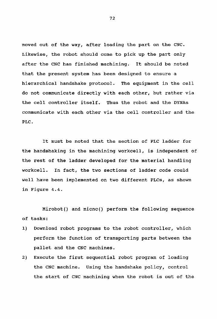
moved out of the way, after loading the part on the CNC.
Likewise, the robot should come to pick up the part only
after the CNC has finished machining. It should be noted
that the present system has been designed to ensure a
hierarchical handshake protocol. The equipment in the cell
do not communicate directly with each other, but rather via
the cell controller itself. Thus the robot and the DYNAs
communicate with each other via the cell controller and the
PLC.
It must be noted that the section of PLC ladder for
the handshaking in the machining workcell, is independent of
the rest of the ladder developed for the material handling
workcell. In fact, the two sections of ladder code could
well have been implemented on two different PLCs, as shown
in Figure 4.4.
Mirobot() and micnc() perform the following sequence
of tasks:
1) Download robot programs to the robot controller, which
perform the function of transporting parts between the
pallet and the CNC machines.
2) Execute the first sequential robot program of loading
the CNC machine. Using the handshake policy, control
the start of CNC machining when the robot is out of the
73
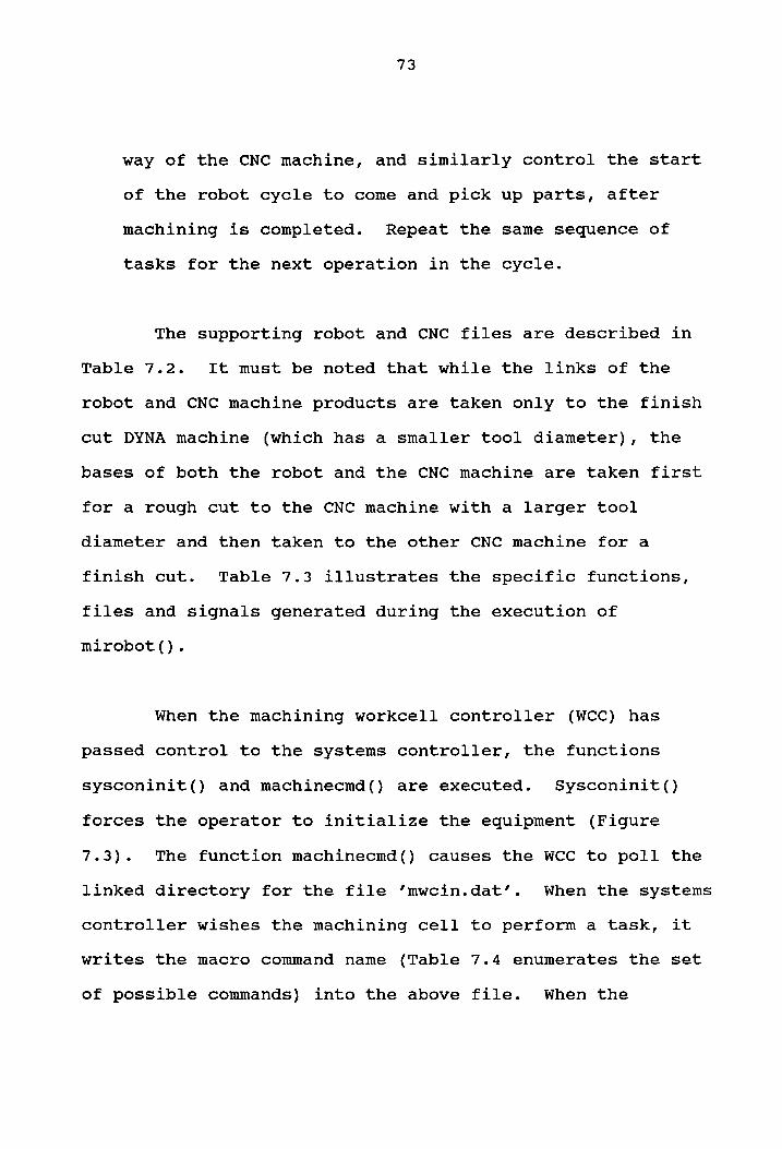
way of the CNC machine, and similarly control the start
of the robot cycle to come and pick up parts, after
machining is completed. Repeat the same sequence of
tasks for the next operation in the cycle.
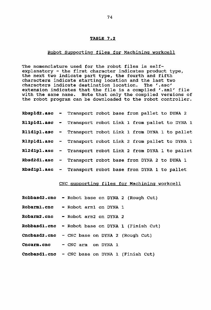
The supporting robot and CNC files are described in
Table 7.2. It must be noted that while the links of the
robot and CNC machine products are taken only to the finish
cut DYNA machine (which has a smaller tool diameter), the
bases of both the robot and the CNC machine are taken first
for a rough cut to the CNC machine with a larger tool
diameter and then taken to the other CNC machine for a
finish cut. Table 7.3 illustrates the specific functions,
files and signals generated during the execution of
mirobot().
When the machining workcell controller (WCC) has
passed control to the systems controller, the functions
sysconinit() and machinecmd() are executed. Sysconinit()
forces the operator to initialize the equipment (Figure
7.3). The function machinecmd() causes the WCC to poll the
linked directory for the file ’mwcin.dat’. When the systems
controller wishes the machining cell to perform a task, it
writes the macro command name (Table 7.4 enumerates the set
of possible commands) into the above file. When the
74
TABLE 7.2
Robot Supporting files for Machining workcell
The nomenclature used for the robot files is self- explanatory - the first character indicates product type, the next two indicate part type, the fourth and fifth characters indicate starting location and the last two characters indicate destination location. The ’.asc’ extension indicates that the file is a compiled ’.aml’ file with the same name. Note that only the compiled versions of the robot program can be downloaded to the robot controller.
Rbspld2.asc
Rlipldi.asc
Rlidipl.asc
Rl2pldil.asc
R12dlpl.ase
Rbsd2dl1.asc
Rbsdipl.asc
Robbasd2.cnce
Robarml1.cne
Robarm2.cne
Robbasdl1.cne
Cnebasd2.cnc
Cncarm.cne
Cnecbasdi1.cne
Transport
- Transport
- Transport
- Transport
- Transport
- Transport
- Transport
robot
robot
robot
robot
robot
robot
robot
base from pallet to DYNA 2
Link 1 from pallet to DYNA 1
Link 1 from DYNA 1 to pallet
Link 2 from pallet to DYNA 1
Link 2 from DYNA 1 to pallet
base from DYNA 2 to DYNA 1
base from DYNA 1 to pallet
CNC supporting files for Machining workcell
- Robot base
- Robot arml
- Robot arm2
~ Robot base
on DYNA 2 (Rough Cut)
on DYNA 1
on DYNA 2
on DYNA 1 (Finish Cut)
- CNC base on DYNA 2 (Rough Cut)
- CNC arm on DYNA 1
- CNC base on DYNA 1 (Finish Cut)
75
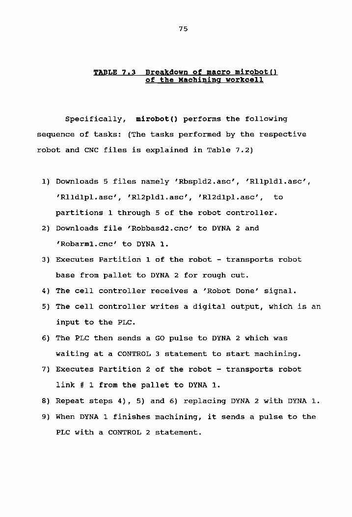
TABLE 7.3 Breakdown of macro mirobot() of the Machining workcell
Specifically, mirobot() performs the following
sequence of tasks: (The tasks performed by the respective
Executes Partition 1 of the robot - transports robot
base from pallet to DYNA 2 for rough cut.
The cell controller receives a ’Robot Done’ signal.
The cell controller writes a digital output, which is an
input to the PLC.
The PLC then sends a GO pulse to DYNA 2 which was
waiting at a CONTROL 3 statement to start machining.
Executes Partition 2 of the robot - transports robot
link # 1 from the pallet to DYNA 1.
Repeat steps 4), 5) and 6) replacing DYNA 2 with DYNA 1.
When DYNA 1 finishes machining, it sends a pulse to the
PLC with a CONTROL 2 statement.
10)
11)
12)
13)
14)
15)
16)
17)
19)
20)
21)
76
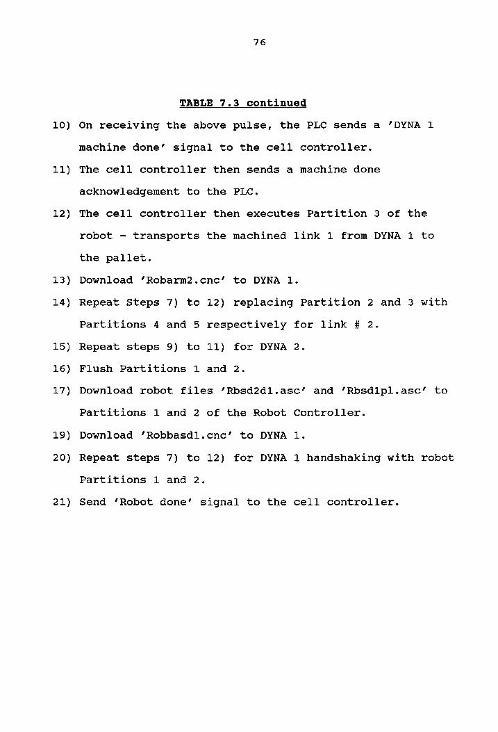
TABLE 7.3 continued
On receiving the above pulse, the PLC sends a ’DYNA 1
machine done’ signal to the cell controller.
The cell controller then sends a machine done
acknowledgement to the PLC.
The cell controller then executes Partition 3 of the
robot - transports the machined link 1 from DYNA 1 to
the pallet.
Download ‘’Robarm2.cnc’ to DYNA 1.
Repeat Steps 7) to 12) replacing Partition 2 and 3 with
Partitions 4 and 5 respectively for link # 2.
Repeat steps 9) to 11) for DYNA 2.
Flush Partitions 1 and 2.
Download robot files ’Rbsd2dl.asc’ and ’Rbsdipl.asc’ to
Partitions 1 and 2 of the Robot Controller.
Download ‘’Robbasdl.cnce’ to DYNA 1.
Repeat steps 7) to 12) for DYNA 1 handshaking with robot
Partitions 1 and 2.
Send ’Robot done’ signal to the cell controller.
77
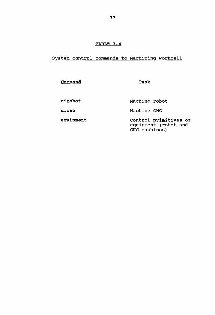
TABLE 7.4
System control commands to Machining workcell
Command
mirobot
micne
equipment
Machine robot
Machine CNC
Control primitives of equipment (robot and CNC machines)
78
machining WCC finds the file in the linked directory, it
reads this file, and executes the routine with the same name
as the command it received (example: when the systems
controller writes "mirobot" in file ’mwcin.dat’, the
function mirobot() is executed by the machining WCC). In
the case when the command read in the file ‘’mwcin.dat’ is
"equipment", then the WCC polls the file ’mwc2in.dat’ for
specific information required for primitive control of
devices in the workcell (example: the strings "downloadrob"
"1" " rbspld2.asc" in file ’mwc2in.dat’ will cause the
machining WCC to download file ‘rbspld2.asc’ to partition 1
of the robot controller). When the WCC has read a task
command, it erases the command input file ’mwcin.dat’ or
‘mwoe2in.dat’). It then creates a status output file
‘mwcout.dat’ and writes a "busy" into this file. The file
‘mwcout.dat’ is monitored by the systems controller ina
Similar manner. When the task has been completed by the
device in the workcell, the WCC sends a "done" status to the
systems controller. The WCC then continues polling the
common linked directory for further command inputs in the
file ’mwcin.dat’. In this way the systems controller and
workcell controller are able to communicate with each other
through appropriately addressed files (envelopes) stored in
a common linked directory (mailbox). The systems controller
is able to achieve control of the workcell capabilities, as
79
well as have status feedback from the workcell. Similar to
the WCC, the systems controller erases the status file
‘mwcout.dat’, after it has been read. It then continues
searching in the linked directory for new status
information.
8. ASSEMBLY WORKCELL
The assembly workcell is responsible for replenishing
raw material feeder brackets, kitting pallets and assembling
the final products. All operations are performed by the
robot using the fixturing in the cell.
Hardware
The equipment under the domain of the assembly cell,
are an IBM 7547 robot, raw material feeders, and assembly
fixtures. The assembly workcell controller is an AT&T 6300
computer with a STARLAN board and a DATA TRANSLATION 2808
board. Port 0O on the DATA TRANSLATION board is currently
linked via a PB16T mounting rack with OPTO22 modules to
robot status outputs. The serial port (COM1) on the mother
board is connected to the robot controller by means of a RS-
232C cable. The IBM 7547 robot controller has within it an
input/output additional expansion unit for additional
digital I/O. There are thus 32 inputs and 32 outputs for
this robot. Only 4 inputs are being currently used however
[2].
80
81
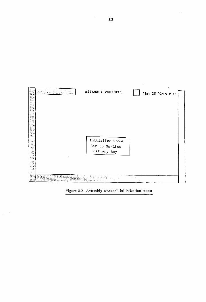
Software
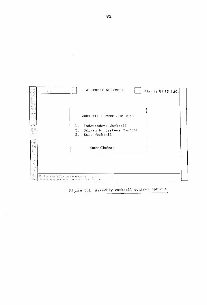
The assembly workcell controller software menu system
asswee functions much like the software system for the
machining workcell. The user is presented with a menu
(Figure 8.1), which requests input designating the desired
mode of operation - locally controlled or controlled by the
systems controller. Both modes of operation will require
initialization of the robot and this is done through the
menu given in Figure 8.2. The routines developed to
accomplish the above tasks are: return_home() and
autostart().
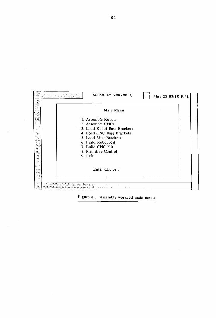
Local control of the assembly workcell is
accomplished through the menus given in Figure 8.3. Eight
different tasks can be performed. Seven of these tasks are
executed through command/communication macro routines, as
described in the machining workcell software description.
The last task, ’Primitive Control’, provides primitive
control access to the robot controller.
Asrobot() and ascnc() routines are used to assemble
the robot and CNC machines. To build robot and CNC kits,
burobot(), and bucnc() are executed. Lorobot(), locnce() and
lolink() cause the robot to replenish raw material feeders
82
ASSEMBLY WORKCELL [|] May 28 02:15 P.M.|
WORKCELL CONTROL OPTIONS
re Independent Workcell
Driven by Systems Control
3. Exit Workcell
Bh
Enter Choice :
Figure 8.1 Assembly workcell control options
83
ASSEMBLY WORKCELL [ | May 28 02:15 P.M
Initialize Robot
Set to On-Line
Hit any key
Figure 8.2 Assembly workcell initialization menu
84
ASSEMBLY WORKCELL [| May 28 02:15 P.M.
Main Menu
. Assemble Robots
. Assemble CNCs
. Load Robot Base Brackets
. Load CNC Base Brackets
. Load Link Brackets
. Build Robot Kit
. Build CNC Kit
. Primitive Control
. Exit
Ooo NN WY
Enter Choice :
Figure 8.3 Assembly workcell main menu
85
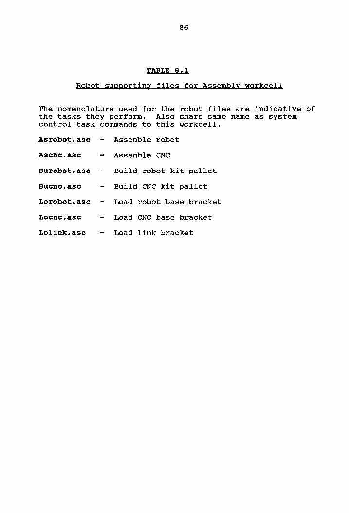
for robot bases, CNC bases and links respectively. These
macros are routines which download and execute robot files
with the same names as the routines themselves, with an
‘.asc’ file extension. Table 8.1 lists the various robot
files.
When the assembly workcell is driven by the systems
controller, the communications involved are similar to that
discussed in Chapter 7 for the machining workcell. The
workcell controller polls the file ’awcin.dat’ for commands
from the systems controller, and writes status information
into the file ’awcout.dat’. File ‘’awc2in.dat’ is used by
the systems controller to control the primitives of the
assembly workcell robot. Table 8.2 summarizes the commands
from the systems controller to the assembly workcell.
86
TABLE 8.1
Robot supporting files for Assembly workcell
The nomenclature used for the robot files are indicative of the tasks they perform. Also share same name as system control task commands to this workcell.
Asrobot.asc - Assemble robot
Ascnc.asc - Assemble CNC
Burobot.asce - Build robot kit pallet
Bucnc.asc - Build cCNC kit pallet
Lorobot.asc - Load robot base bracket
Locnec.asc - Load CNC base bracket
Lolink.asc - Load link bracket
87
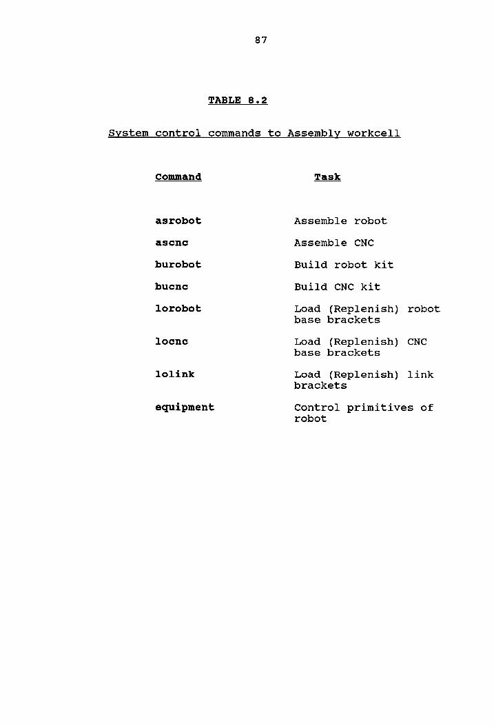
TABLE 8.2
System control commands to Assembly workcell
Command Task
asrobot Assemble robot
ascne Assemble CNC
burobot Build robot kit
bucne Build CNC kit
lorobot Load (Replenish) robot base brackets
locne Load (Replenish) CNC base brackets
lolink Load (Replenish) link brackets
equipment Control primitives of robot
9. MATERIAL HANDLING
The material handling workcell is responsible for
storage, transportation, and inspection. Currently, since
the vision system and the AS/RS have not yet been
incorporated, its basic task is transportation of pallets
between the operator interface, storage, assembly workcell
and machining workcell.
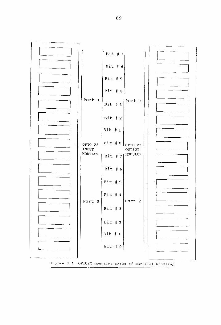
Hardware
The conveyor used for transportation is a
Shuttleworth conveyor system. Control and status monitoring
of conveyor motion is achieved with TI565 PLC inputs and
outputs. The material handling workcell controller is an
AT&T 6300 computer with a STARLAN board and a DI064 board
manufactured by Industrial Computer Source. The DI064 board
has 8 ports of 8 bits each (totalling 64 I/O points), and
configured into 4 sets. Each set has 16 bits of
programmable input/output. Currently 2 sets of bits are
being used to interface with 2 Optomation PB16A mounting
racks (Figure 9.1). Set 1, which has Port 0 (lower 8
positions) and Port 1 (upper 8 positions), is connected via
88
O04,
Figure 9.1
Port 1
OPTO 22
INPUT
MODULES
Port 0
Bit
Bit
Bit
Bit
Bit
Bit
Bit
Bit
Bit
Bit
Bit
Bit
Bit
Bit
Bit
Bit
89
#7
# 6
#5
# 4
#3
# 2
# 1
# 0
#7
# 6
#5
#4
# 3
# 2
# 1
#0
Port 3
OPTO 22
OUTPUT
HODULES
Port 2
OU
OPTO22 mounting racks of material handling
90
ribbon cable to the mounting rack with digital input
modules. These input modules are activated by PLC outputs
for conveyor and AS/RS status. Set 2, which has Port 2
(lower 8 bits) and Port 3 (upper 8 bits), is connected to a
mounting rack with digital output modules. These outputs
from the cell controller are conveyor and AS/RS command
inputs to the PLC.
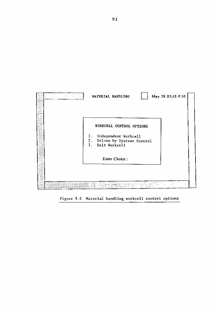
Software
Like the other workcell controllers, this cell
software mhlwce also affords the opportunity to run the
system from the systems controller, or independent of it,
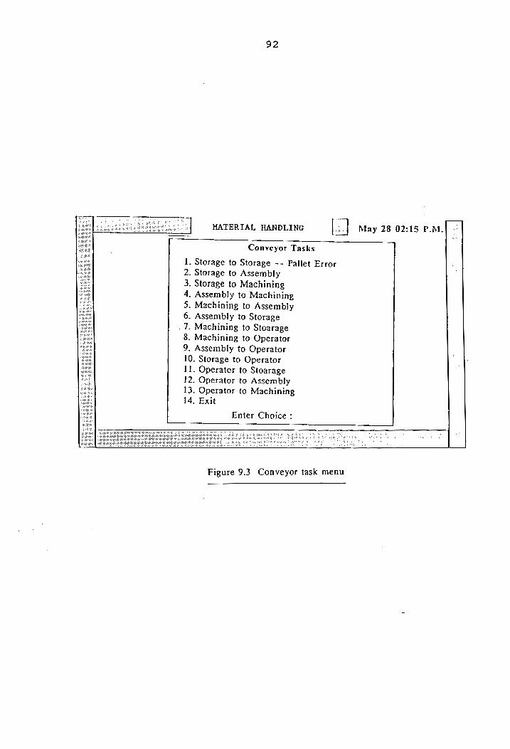
from the workcell itself (Figure 9.2). During local
control, the user can make the conveyor transport a pallet
from one location to another (Figure 9.3), using macros
developed which interface with the PLC program developed by
Muralikrishnan et al. [14]. Each macro basically sends a
conveyor task code (see Table 9.1) on the workcell digital
output port 2 (bits 0 through 3), which are inputs to the
PLC. The macros are named according to their source and
destination. The macros developed are sttost(), sttoas(),
Figure 9.2 Material handling workcell control options
92
MATERTAL HANDLING May 28 02:15 P.M.
Conveyor Tasks
. Storage to Storage -- Pallet Error
. Storage to Assembly
. Storage to Machining
. Assembly to Machining - Machining to Assembly . Assembly to Storage . Machining to Stoarage . Machining to Operator . Assembly to Operator
10. Storage to Operator 11. Operator to Stoarage 12. Operator to Assembly
13. Operator to Machining 14. Exit
DOONAN
A DW
DO =
Enter Choice :
Figure 9.3 Conveyor task menu
93
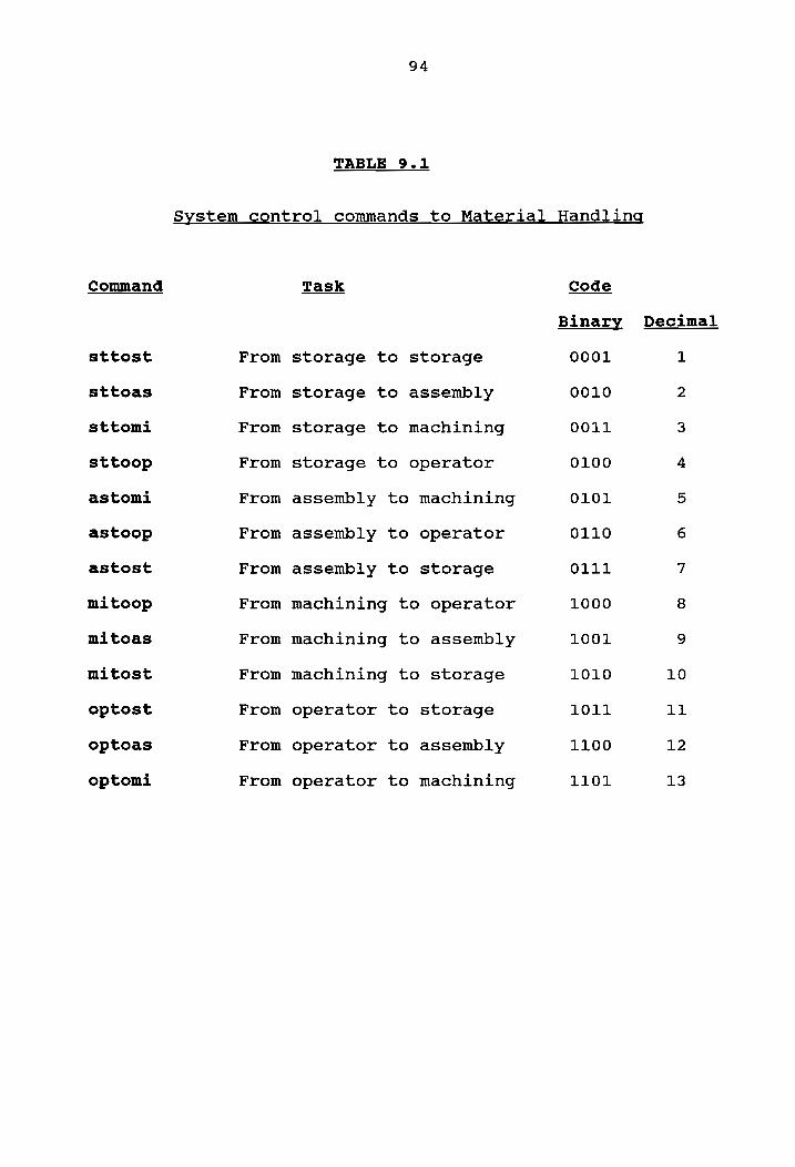
As in the case of the other workcells, when the
material handling workcell is driven by the systems
controller, it executes macros of the same name as the
command it receives from the controller (Table 9.1).
Command
sttost
sttoas
sttomi
sttoop
astomi
astoop
astost
mitoop
mitoas
mitost
optost
optoas
optomi
From
From
From
From
From
From
From
From
From
From
From
From
From
94
TABLE 9.1
storage to storage
storage to assembly
storage to machining
storage to operator
assembly to machining
assembly to operator
assembly to storage
machining to operator
machining to assembly
machining to storage
operator to storage
operator to assembly
operator to machining
System control commands to Material Handling
0101
0110
0111
1000
1001
1010
1011
1100
1101
Decimal
10
11
12
13
10. SYSTEMS CONTROLLER
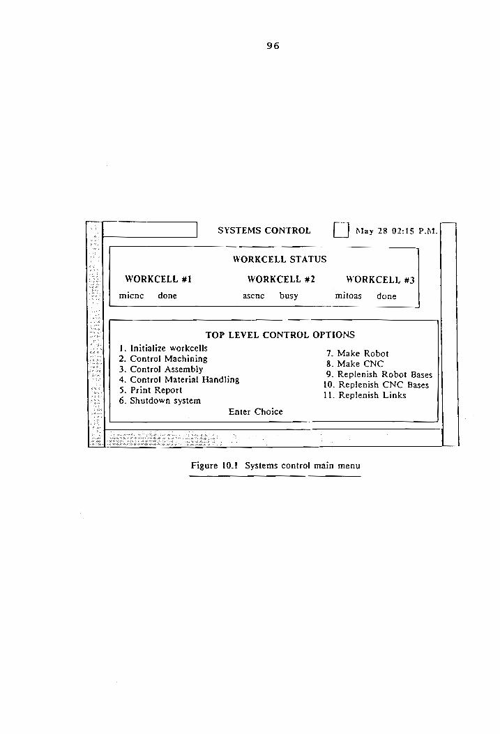
The systems controller is responsible for
coordinating the activities of the different workcells. It
is linked to the other workcell controllers only by STARLAN.
It is not hardwired to any device and does not have any cell
I/O of its own, unlike the other cell controllers. However
the systems controller software syscon has been provided the
ability to control the primitives of equipment in the 3
workcells under its domain. It also can execute all the
macros of the workcells, described above, with status
feedback (Figure 10.1). This control and status feedback is
achieved by having a strong message system.
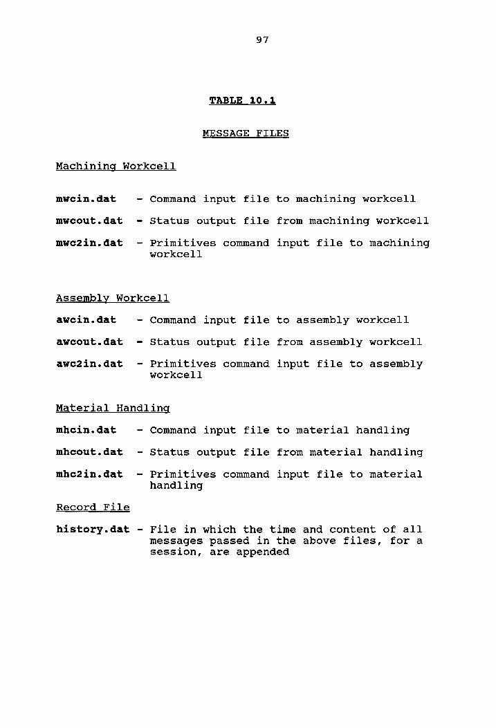
Each cell controller has associated with it two input
and one output files. Table 10.1 summarizes the input and
output files through which the systems controller and the
workcell controllers communicate with each other. The
command input files to the workcell controllers have an
‘in.dat’ ending, while the status output files from the
workcell controllers which are read by the systems
controller have an ’out.dat’ ending. When the primitives of
equipment of either the machining or assembly workcell are
95
96
SYSTEMS CONTROL [ | May 28 02:15 P.M.
WORKCELL STATUS
WORKCELL #1 WORKCELL #2 WORKCELL #3
micnc done ascnc busy mitoas done
TOP LEVEL CONTROL OPTIONS
1. Initialize workcells
2. Control Machining r Mone ae 3. Control Assembly . 9. Replenish Robot Bases 4. Control Material Handling 10. Replenish CNC Bases 5. Print Report 11. Replenish Links 6. Shutdown system
Enter Choice
Figure 10.! Systems control main menu
97
TABLE 10.1
MESSAGE FILES
Machining Workcell
mwcin.dat - Command input file
mweout.dat - Status output file
mwe2in.dat - Primitives command workcell
Assembly Workcell
awein.dat - Command input file
awceout.dat - Status output file
awc2in.dat - Primitives command workcell
Material Handling
mhcin.dat - Command input file
mhcout.dat - Status output file
mhc2in.dat - Primitives command handling
Record File
history.dat
to machining workcell
from machining workcell
input file to machining
to assembly workcell
from assembly workcell
input file to assembly
to material handling
from material handling
input file to material
File in which the time and content of all messages passed in the above files, fora session, are appended
98
to be controlled from the systems controller, the message
written into ’mwcin.dat’ or ‘awcin.dat’ is "equipment",
while the specific task and associated variables for the
primitive control is written in the relevant workcell input
file with filename ending ’2in.dat’. In the former case the
wcc uses the routine communicatein() to read the task
command, while in the latter the WCC reads the specific task
variables with the routine c2ommunicatein() developed in the
toolkit file ’lan.h’.
All the primitives of the three workcells, except the
read_io(), read_reject_status() and read_machine_status(),
developed for the robots in the machining and assembly
workcells, are implementable from systems control.
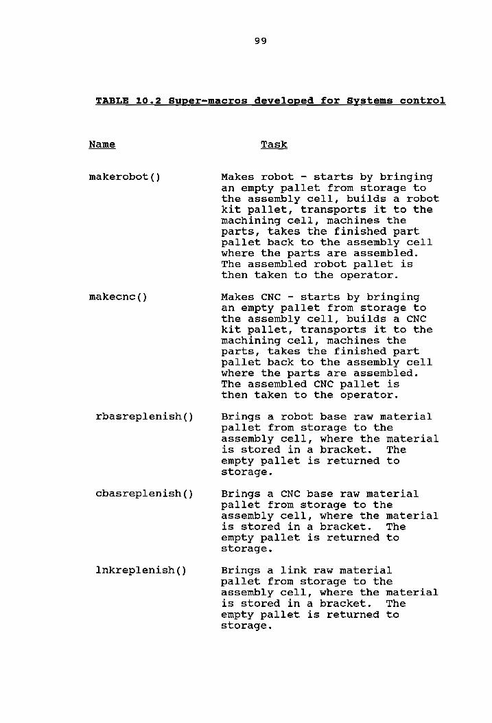
The systems controller has cell control "super-macros"
to automate the whole FMS, by sequencing the macros of the
different workcells, to achieve co-ordination between
workcells (Table 10.2). There are 5 super-macros grouped
into two sets of functions: Rbasreplenish(), cbasreplenish()
and lnkreplenish() replenish raw material stock from storage
to the part feeders. Makerobot() and makecnc() take an
empty pallet through the kit building, machining, assembly
and transportation processes necessary to make a robot or a
CNC machine.
99
TABLE 10.2 Super-macros developed for Systems control
Name
makerobot ()
makecnc()
rbasreplenish()
cbasreplenish()
lnkreplenish ()
Task
Makes robot - starts by bringing an empty pallet from storage to the assembly cell, builds a robot kit pallet, transports it to the machining cell, machines the parts, takes the finished part pallet back to the assembly cell where the parts are assembled. The assembled robot pallet is then taken to the operator.
Makes CNC - starts by bringing an empty pallet from storage to the assembly cell, builds a CNC kit pallet, transports it to the machining cell, machines the parts, takes the finished part pallet back to the assembly cell where the parts are assembled. The assembled CNC pallet is then taken to the operator.
Brings a robot base raw material pallet from storage to the assembly cell, where the material is stored in a bracket. The empty pallet is returned to storage.
Brings a CNC base raw material pallet from storage to the assembly cell, where the material is stored in a bracket. The empty pallet is returned to storage.
Brings a link raw material pallet from storage to the assembly cell, where the material is stored in a bracket. The empty pallet is returned to storage.
100
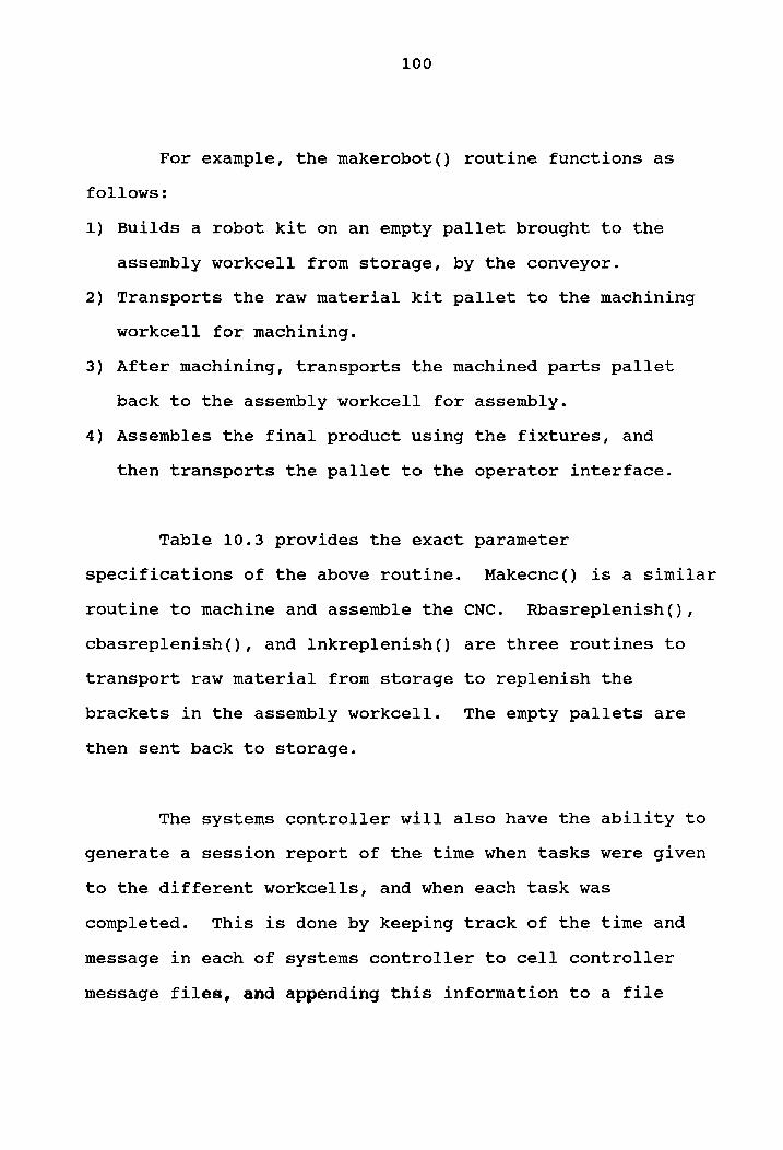
For example, the makerobot() routine functions as
follows:
1) Builds a robot kit on an empty pallet brought to the
assembly workcell from storage, by the conveyor.
2) Transports the raw material kit pallet to the machining
workcell for machining.
3) After machining, transports the machined parts pallet
back to the assembly workcell for assembly.
4) Assembles the final product using the fixtures, and
then transports the pallet to the operator interface.
Table 10.3 provides the exact parameter
specifications of the above routine. Makecnc() is a similar
routine to machine and assemble the CNC. Rbasreplenish(),
cbhasreplenish(), and lnkreplenish() are three routines to
transport raw material from storage to replenish the
brackets in the assembly workcell. The empty pallets are
then sent back to storage.
The systems controller will also have the ability to
generate a session report of the time when tasks were given
to the different workcells, and when each task was
completed. This is done by keeping track of the time and
message in each of systems controller to cell controller
message files, and appending this information to a file
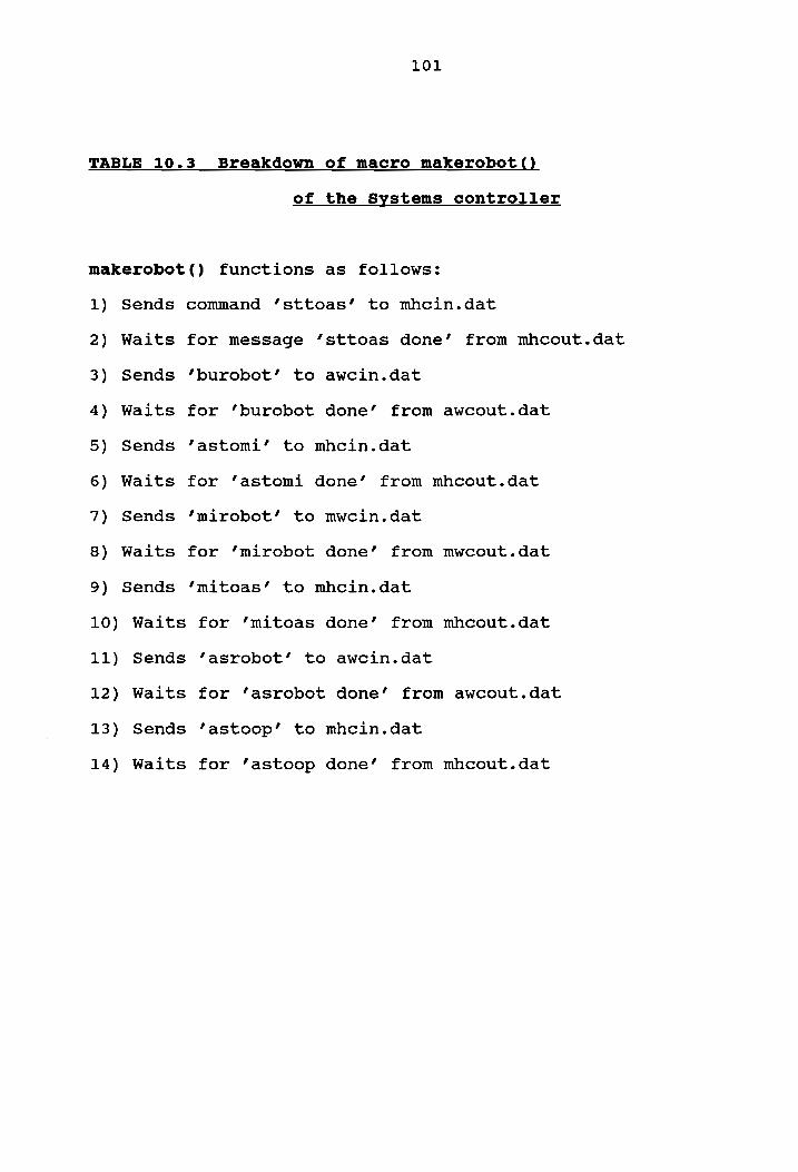
TABLE 10.3
101
Breakdown of macro makerobot()
of the Systems controller
makerobot() functions as follows:
1)
2)
3)
4)
5)
6)
7)
8)
9)
10)
11)
12)
13)
14)
Sends
Waits
Sends
Waits
Sends
Waits
Sends
Waits
Sends
Waits
Sends
Waits
Sends
Waits
command ‘’sttoas’ to mhcin.dat
for message ’sttoas done’ from mhcout.dat
‘burobot’ to awcin.dat
for ‘’burobot done’ from awcout.dat
‘astomi’ to mhcin.dat
for ‘astomi done’ from mhcout.dat
‘mirobot’ to mwcin.dat
for ‘mirobot done’ from mwcout.dat
‘mitoas’ to mhcin.dat
from mhcout.dat for ‘mitoas done’
‘asrobot’ to awcin.dat
for ‘asrobot done’ from awcout.dat
‘astoop’ to mhcin.dat
for ‘’astoop done’ from mhcout.dat
102
‘history.dat’, before erasing the message file. The
function record() achieves this ability.
11. CONCLUSIONS & RECOMMENDATIONS
There were two objectives of this project:
1) to develop a test and debug capability for the
communication links within an FMS, and
2) to demonstrate the direct applicability of primitive
communication routines developed, to achieve high
level operations for an integrated and automated
system.
Both of the objectives were met successfully. A
toolkit of functions was augmented and modified to enable
control of robots, CNC machines, and workcell digital I/O
using DATA TRANSLATION 2808 and DI064 boards. The toolkit
also includes functions for generic serial and LAN
communications. For the serial communications aspect,
routines have been developed which can be used to
communicate over a RS-232C serial line, using any set of
transmission parameters. For the LAN communications aspect,
routines have been developed which enable message passing
between computers. The developed toolkit functions insulate
the user from lower level communications. The user can
directly use the library functions to implement more complex
103
104
communications. The routines of the toolkit can be
exercised by the user by using a menu driven program
toolkit.
The toolkit functions that were developed were
demonstrated on an FMS. The FMS was divided into three
workcells. Each workcell was controlled by a workcell
controller, itself under the supervision of a systems
controller. The workcell controllers themselves were
hardwired to equipment like robots, CNC machines and
material handling equipment. The FMS was integrated as one
unit, and made driveable from systems control. The systems
controller was given the ability to control the primitives
of the equipment of the different workcells, as well as
control execution of a sequence of macros developed for the
different workcells.
Currently the FMS has been implemented without using
an AS/RS or a vision system. Future work can involve
integration of these two modules into the system.
Alongside, with the implementation of the AS/RS and vision
system, it is also necessary to develop software to keep
track of the inventory in the system.
105
The present material handling system software has
been developed for a single pallet in the system. Future
work can be directed towards expanding this to a ‘’multiple
pallet on conveyor’ system. This will require accounting
for scheduling features.
The present system software assumes an ideal
operation - the ability to detect errors and recover from
them has been beyond the scope of this project. Future work
can involve incorporation of a higher level AI controller,
which schedules and prioritizes tasks, keeps track of
inventory ina data base, and is able to intelligently
recover from errors.
106
REFERENCES
Bidani, S., "The Applicability of APT towards meeting
Control needs in Discrete Parts Manufacturing," IEOR MS
Thesis, Virginia Polytechnic Institute and State
University, Sept 1989.
CIM Laboratory Cable Documentation, March 1989
Data Translation Inc., "Personal Computer series user
manual for DT 2808 single board analog and digital I/0O
system," Data Acquisition and Control Products, 1983.
Dyna Electronics product manual, "DM 2400/2200
Programming manual."
Dutton, D.J., "The Design and Implementation of a Cell
Controller," M. S. Thesis, Department of Industrial and
Systems Engineering, Georgia Institute of Technology,
1987.
Economy, T. et al., "Assembly Workcell Report," IEOR
5324 Class Project, Spring 1990.
Ekong, Etim S., "Controls : The Bridge to Systems
Integration," 16th Annual International Programmable
Controllers Conference and Exposition, Detroit, Michigan, April 7-9, 1987.
10.
11.
12.
13.
14.
15.
107
Grierson, D. K., "Factory Automated Systems - Solutions
through integration," Autofact 5, MS83-731, 1983.
Guleri, A., "Device Driver Development and
Implementation for Workcell Control," IEOR M.E.
Project, Virginia Polytechnic Institute and State
University, Dec 1988.
IBM Manufacturing System Software Library, "Aml/Entry
Version 4 User’s Guide," Second edition, August 1988.