• Choosing a high-density WLAN capacity goal: – Total # of devices = seats X devices per seat
• A user may have a laptop & Wi-Fi smartphone• Each MAC address uses airtime, IP address, etc.
– Minimum bandwidth per device – driven by mix of data, voice and video applications used
– Common examples of a complete capacity goal:• Classroom has 30 students each needs 2 Mbps• Auditorium holds 500 people w/laptop at 350 Kbps for data and a
voice handset at 128 Kbps• Trading floor of 800 people with 512 Kbps each
– Try to plan for future capacity needs in the design– Number of seats may remain fixed, but number of devices
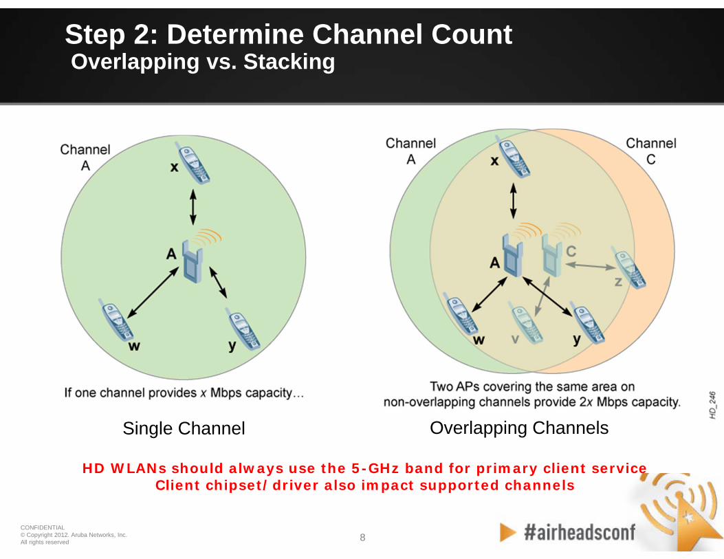
Step 2: Determine Channel Count20 MHz vs. 40 MHz Channels
• High-throughput 40-MHz (HT40) channels – Reduces number of radio channels by bonding them together
to achieve higher throughput– Reduced max. number of client devices supported– HT40 channels not used on the 2.4-GHz band– Main benefit — ability to burst at the max. PHY
• But, auditoriums must support so many users in a single room that every possible channel is needed– Trade-off: Reduce max. burst rate in exchange for a
greater total user capacity• Therefore, most HD WLANs including auditoriums
should use 20-MHz channel widths, also known as HT20
Step 2: Determine Channel Count To DFS or Not to DFS?
• The DFS 5-GHz band, with up to twenty 20-MHz channels, can achieve high performance in a 500-seat auditorium
• Without DFS, the goal can be achieved but with oversubscribed radios & lower per-client throughput
So why wouldn’t everyone use DFS? • Three significant exceptions could adversely affect
HD WLAN performance with DFS enabled: – Proximity to radar sources in the 5250-MHz to 5725-MHz band– Lack of DFS support on critical client devices– The Receive Sensitivity Tuning-Based Channel Reuse feature of
• Validate whether the entire HD coverage area will meet the capacity goal you chose in Step #1.
• It is common for the wireless architect to have to follow an iterative process and compromise between channel count, radio loading and minimum per-client throughput.
• If the capacity prediction in Step #4 falls short of the capacity goal, repeat the first four steps until you achieve the best balance to achieve your goal.
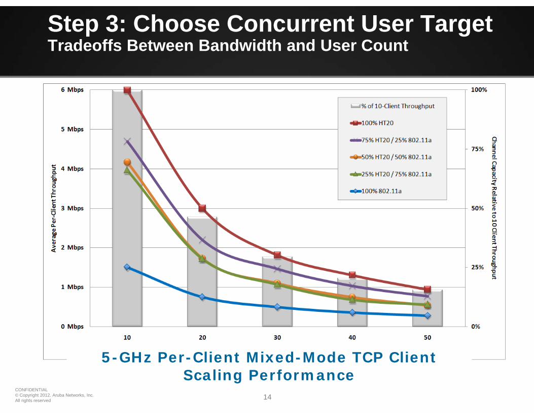
• For large auditoriums over 500 seats, you should be prepared to accept a per-client throughput of 500 Kbps or less, assuming a 50/50 mix of .11n and .11a stations and nine usable channels.
• Channel reuse not possible.• Inconsistent signal levels.• Increased body attenuation.• Harder to control CCI/ACI.• Signal bleed outside area.
AP Coverage Strategies – Pros and Cons
OverheadCoverage
• Can be concealed inside ceiling.• Mounted above eye level.• Uniform signal, APs evenly spaced.• Clear line-of-sight to devices.• Minimal human-body attenuation.• Better CCI/ACI control.
PROs CONsStrategy• Channel reuse not possible.• Difficult to pull cable.
SideCoverage
• Easy to install and pulling cable.• Columns can be used to deliberately
create RF shadows.
• Access underneath the auditorium.
• Availability of cable pathways beneath the floor.
FloorCoverage
• Channel reuse possible.• Higher AP densities can be achieved.• APs can be easily concealed.• More uniform signal in the room.• Clear line-of-sight to devices.• Minimal human-body attenuation.• Better CCI/ACI control.
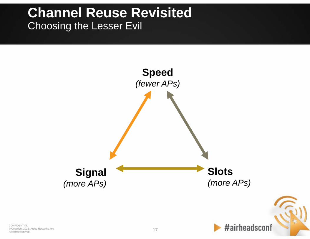
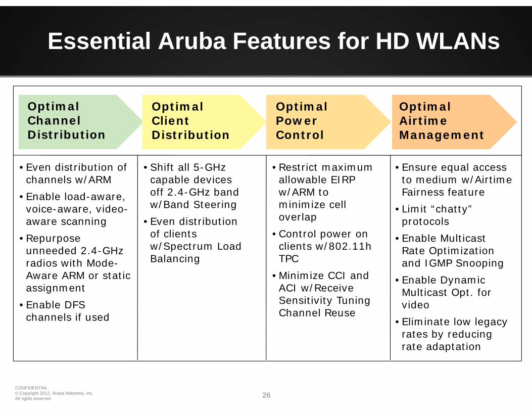
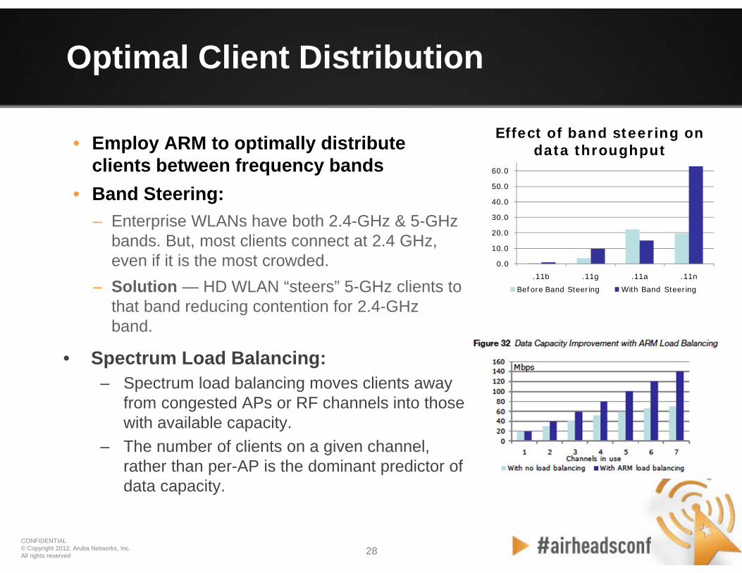
• Optimize the distribution of RF spectrum to APs and clients to make best use of scarce spectrum– Use as many allowed RF channels as possible and ensure
they are properly distributed• ARM Channel Selection
– Aruba ARM uses distributed channel reuse mgmt. algorithm– This iterative process converges quickly on optimum channel
plan for the entire network• Mode-Aware ARM
– Dynamically shifts surplus radios in the same RF neighborhood to become air monitors
– Mode-Aware ARM is disabled by default– APs cannot be individually configured for Mode-Aware
• Huge convention center located in Singapore• 5 levels of convention halls• Grand ballroom on level 5• Can be over 5000 users per level• No control over client devices—can be any type
of device• Distribution of 2.4 GHz and 5.0 GHz clients
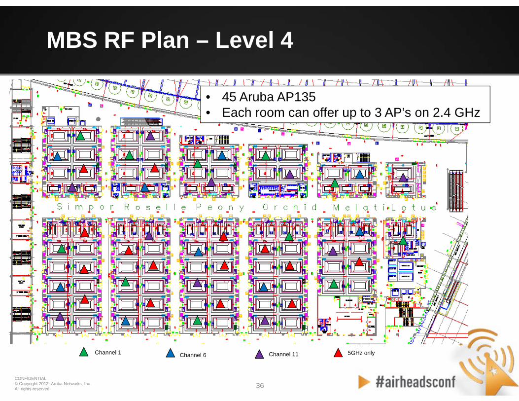
• Series of rooms that are largely self contained user spaces• Channel reuse within each room is not possible• 2.4 GHz channels are statically set to ensure 3 non-overlapping
channels per room• 2.4 GHz transmit power is statically set to 15 dBm• 5.0 GHz channels and transmit power are automatically
configured with ARM—ARM has configured all AP’s to use max power
• Signal overlap from one room to the next is minimal• Interference is minimal• Ceiling placement gives Line of Sight (LOS) to clients and
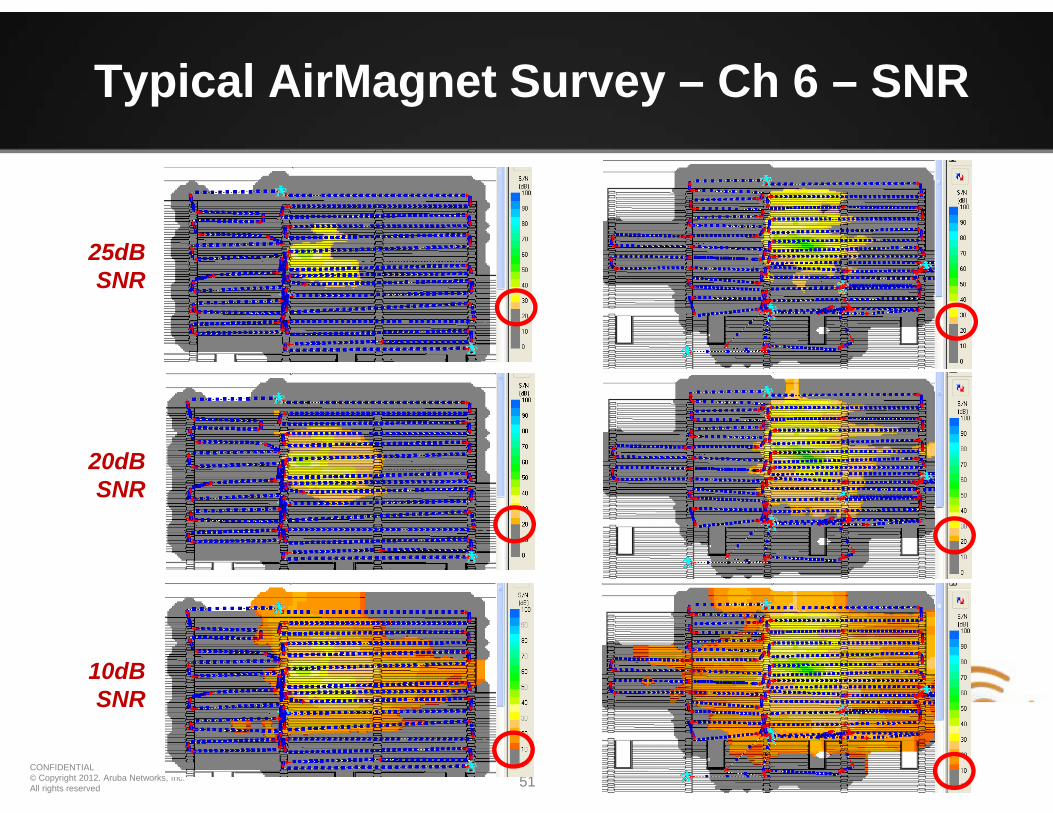
provide strong coverage• SNR is strong within each room giving excellent performance
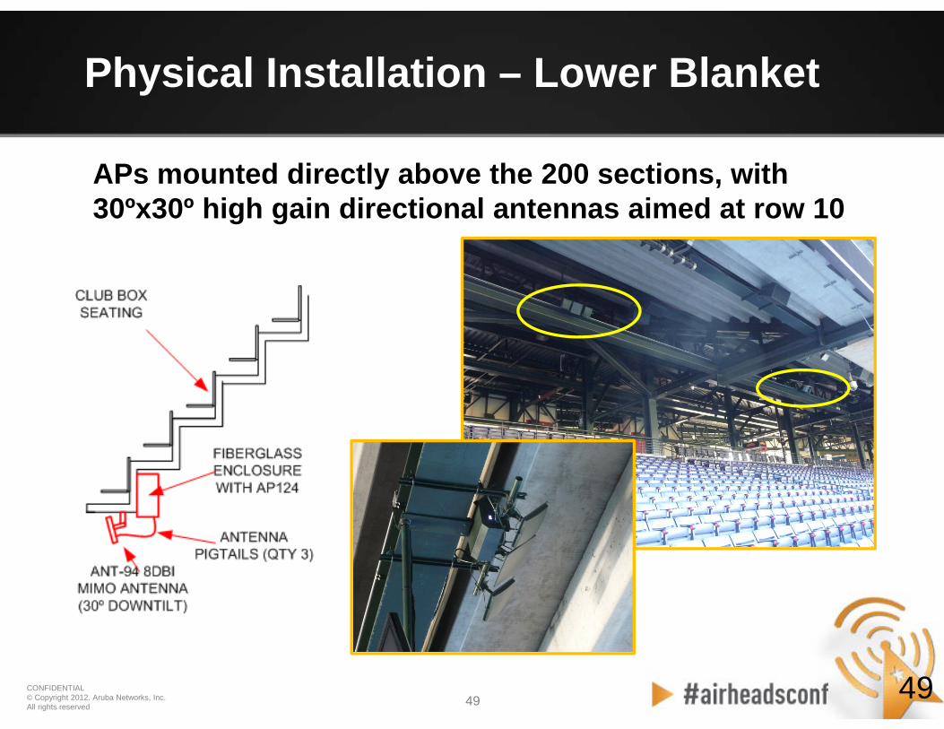
• Three interleaved “blankets” of APs to cover the lower sections, club level, and upper sections respectively:– Lower deck antennas are mounted under the club seats and
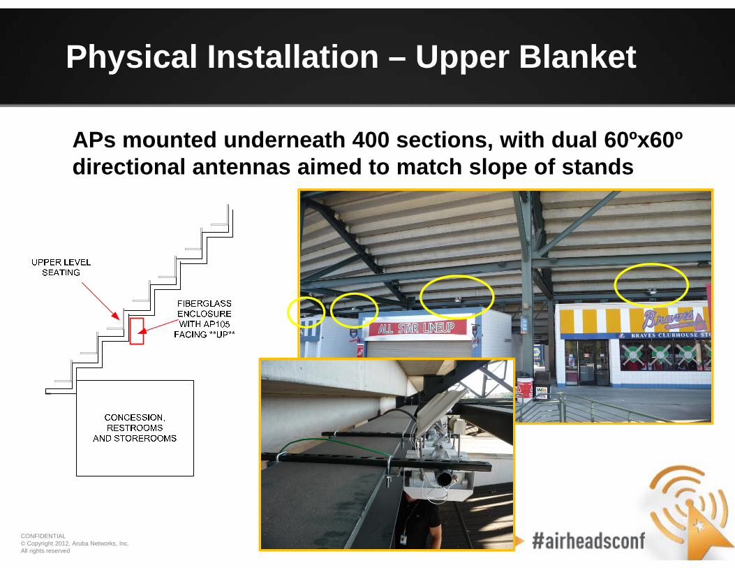
aimed “out” to the field– Upper deck antennas are mounted underneath the floor and
aimed straight “up” through the concrete. In the middle– A blanket of APs is installed in the club suites above the
ceiling.
• The stadium structure itself is used to minimize interference between blankets
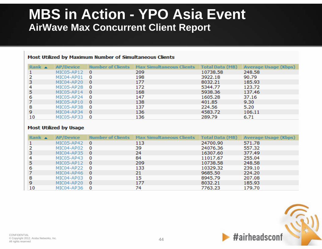
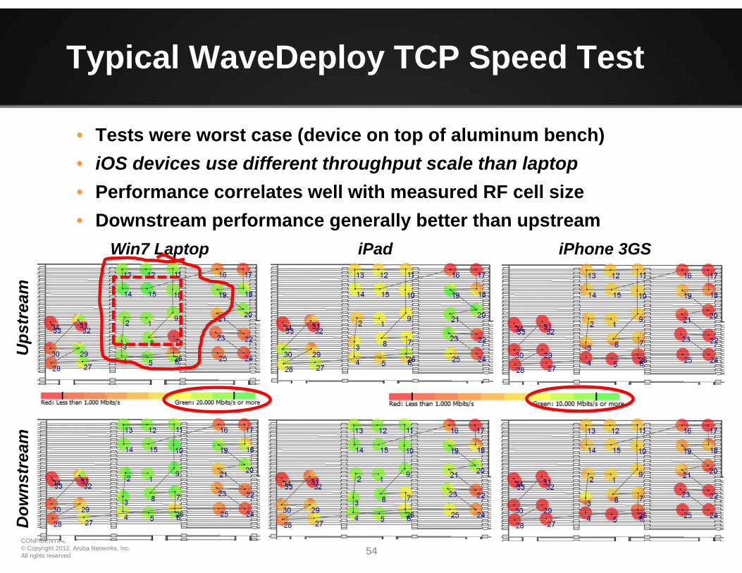
• Tests were worst case (device on top of aluminum bench)• iOS devices use different throughput scale than laptop• Performance correlates well with measured RF cell size• Downstream performance generally better than upstream